dnvgl-ru-ship-pt4ch8 electrical installations · rules for classification: ships —...
TRANSCRIPT

The content of this service document is the subject of intellectual property rights reserved by DNV GL AS ("DNV GL"). The useraccepts that it is prohibited by anyone else but DNV GL and/or its licensees to offer and/or perform classification, certificationand/or verification services, including the issuance of certificates and/or declarations of conformity, wholly or partly, on thebasis of and/or pursuant to this document whether free of charge or chargeable, without DNV GL's prior written consent.DNV GL is not responsible for the consequences arising from any use of this document by others.
The electronic pdf version of this document, available free of chargefrom http://www.dnvgl.com, is the officially binding version.
DNV GL AS
RULES FOR CLASSIFICATION
ShipsEdition October 2015
Part 4 Systems and components
Chapter 8 Electrical installations

FOREWORD
DNV GL rules for classification contain procedural and technical requirements related to obtainingand retaining a class certificate. The rules represent all requirements adopted by the Society asbasis for classification.
© DNV GL AS October 2015
Any comments may be sent by e-mail to [email protected]
If any person suffers loss or damage which is proved to have been caused by any negligent act or omission of DNV GL, then DNV GL shallpay compensation to such person for his proved direct loss or damage. However, the compensation shall not exceed an amount equal to tentimes the fee charged for the service in question, provided that the maximum compensation shall never exceed USD 2 million.
In this provision "DNV GL" shall mean DNV GL AS, its direct and indirect owners as well as all its affiliates, subsidiaries, directors, officers,employees, agents and any other acting on behalf of DNV GL.
Part
4 C
hapt
er 8
Cha
nges
- c
urre
nt
Rules for classification: Ships — DNVGL-RU-SHIP-Pt4Ch8. Edition October 2015 Page 3Electrical installations
DNV GL AS
CHANGES – CURRENT
This is a new document.
The rules enter into force 1 January 2016.

Part
4 C
hapt
er 8
Con
tent
s
Rules for classification: Ships — DNVGL-RU-SHIP-Pt4Ch8. Edition October 2015 Page 4Electrical installations
DNV GL AS
CONTENTS
Changes – current...................................................................................................... 3
Section 1 Service Description...................................................................................101 Application............................................................................................10
1.1 General............................................................................................. 102 Verification Scheme.............................................................................. 10
2.1 General............................................................................................. 112.2 Documentation requirements............................................................... 112.3 Equipment certification........................................................................152.4 Onboard survey................................................................................. 17
Section 2 System Design..........................................................................................191 General................................................................................................. 19
1.1 Design principles................................................................................ 191.2 System voltages and frequency............................................................21
2 Main Electric Power Supply System...................................................... 242.1 General............................................................................................. 242.2 System functionality........................................................................... 25
3 Emergency Power Supply System.........................................................273.1 General............................................................................................. 273.2 Transitional source..............................................................................323.3 Emergency generators........................................................................ 33
4 Battery Systems................................................................................... 344.1 General............................................................................................. 34
5 Starting Arrangement for Engines with Electric Starter........................ 355.1 General............................................................................................. 35
6 Electric Power Distribution................................................................... 366.1 Distribution in general........................................................................ 366.2 Lighting.............................................................................................376.3 Power supply to control and monitoring systems.................................... 396.4 Low voltage shore connections.............................................................40
7 Protection............................................................................................. 407.1 System protection.............................................................................. 407.2 Circuit protection................................................................................427.3 Generator protection...........................................................................457.4 Transformer protection........................................................................ 46

Part
4 C
hapt
er 8
Con
tent
s
Rules for classification: Ships — DNVGL-RU-SHIP-Pt4Ch8. Edition October 2015 Page 5Electrical installations
DNV GL AS
7.5 Motor protection.................................................................................467.6 Battery protection.............................................................................. 477.7 Harmonic Filter protection................................................................... 47
8 Control of Electric Equipment............................................................... 478.1 Control circuits...................................................................................478.2 Control of generator sets and main switchboards....................................488.3 Control of emergency generator set and emergency switchboard.............. 508.4 Control of switchgear and controlgear...................................................518.5 Motor control..................................................................................... 518.6 Emergency stop................................................................................. 52
9 Vessel Arrangement..............................................................................549.1 General............................................................................................. 549.2 Switchboard arrangement....................................................................559.3 Rotating machines..............................................................................569.4 Battery installations............................................................................569.5 Cable routing.....................................................................................599.6 Lightning protection............................................................................609.7 Earthing of aluminium superstructures on steel vessels........................... 60
10 Cable Selection................................................................................... 6010.1 General........................................................................................... 6010.2 Cable temperature............................................................................ 6210.3 Choice of insulating materials............................................................ 6210.4 Rating of earth conductors.................................................................6310.5 Correction factors............................................................................. 6410.6 Parallel connection of cables.............................................................. 6510.7 Additional requirements for AC installations, and special DC installations...6510.8 Rating of cables.............................................................................. 66
Section 3 Equipment in General..............................................................................691 General Requirements.......................................................................... 69
1.1 References.........................................................................................692 Environmental Requirements................................................................69
2.1 Inclination......................................................................................... 692.2 Vibration and acceleration................................................................... 692.3 Temperature and humidity...................................................................69
3 Equipment Ratings................................................................................703.1 Electrical parameters.......................................................................... 703.2 Maximum operating temperatures........................................................ 71
4 Mechanical and Electrical Properties.....................................................71

Part
4 C
hapt
er 8
Con
tent
s
Rules for classification: Ships — DNVGL-RU-SHIP-Pt4Ch8. Edition October 2015 Page 6Electrical installations
DNV GL AS
4.1 Mechanical strength............................................................................714.2 Cooling and anti-condensation............................................................. 724.3 Termination and cable entrances.......................................................... 734.4 Equipment protective earthing............................................................. 744.5 Enclosures ingress protection...............................................................744.6 Clearance and creepage distances........................................................ 75
5 Marking and Signboards....................................................................... 755.1 General............................................................................................. 75
6 Insulation............................................................................................. 766.1 Insulation materials............................................................................ 76
7 Inspection and testing..........................................................................777.1 General............................................................................................. 77
Section 4 Switchgear and Controlgear Assemblies................................................... 791 Construction......................................................................................... 79
1.1 General............................................................................................. 792 Power Circuits...................................................................................... 83
2.1 Power components in assemblies......................................................... 832.2 Additional requirements for high voltage assemblies............................... 86
3 Control and Protection Circuits.............................................................883.1 Control and instrumentation................................................................ 88
4 Inspection and Testing......................................................................... 894.1 General............................................................................................. 89
Section 5 Rotating Machines.................................................................................... 931 General................................................................................................. 93
1.1 References.........................................................................................931.2 Requirements common to generators and motors................................... 931.3 Instrumentation of machines............................................................... 96
2 Additional Requirements for Generators...............................................962.1 General............................................................................................. 962.2 Voltage and frequency regulation......................................................... 972.3 Generator short circuit capabilities........................................................982.4 Parallel operation................................................................................98
3 Inspection and Testing......................................................................... 983.1 General............................................................................................. 98
Section 6 Power Transformers............................................................................... 1031 General............................................................................................... 103
1.1 General........................................................................................... 103

Part
4 C
hapt
er 8
Con
tent
s
Rules for classification: Ships — DNVGL-RU-SHIP-Pt4Ch8. Edition October 2015 Page 7Electrical installations
DNV GL AS
1.2 Design requirements for power transformers........................................1032 Inspection and Testing....................................................................... 104
2.1 General........................................................................................... 105
Section 7 Semi-conductor assemblies.................................................................... 1071 General Requirements........................................................................ 107
1.1 General........................................................................................... 1071.2 Design and construction requirements.................................................108
2 Inspection and Testing....................................................................... 1112.1 General........................................................................................... 111
Section 8 Miscellaneous Equipment........................................................................1141 General............................................................................................... 114
1.1 Socket outlets and plugs................................................................... 1141.2 Lighting equipment........................................................................... 1141.3 Heating equipment........................................................................... 1141.4 Cooking and other galley equipment................................................... 116
Section 9 Cables.....................................................................................................1171 Application..........................................................................................117
1.1 General........................................................................................... 1172 General Cable Construction.................................................................117
2.1 General........................................................................................... 1172.2 Fire properties..................................................................................1182.3 Conductors...................................................................................... 1182.4 Insulating materials.......................................................................... 1182.5 Wire braid and armour......................................................................1192.6 Protective sheaths............................................................................ 119
3 Low Voltage Power Cables................................................................. 1203.1 Construction of cables rated 0.6/1 kV................................................. 1203.2 Switchboard wires............................................................................ 121
4 High Voltage Cables............................................................................1214.1 Construction of cables rated 1.8/3 kV................................................. 1214.2 Construction of high voltage cables rated above 1.8/3 kV.......................122
5 Control and Instrumentation Cables................................................... 1225.1 Construction of control and instrumentation cables rated 150/250 V........ 122
6 Data Communication Cables............................................................... 1236.1 General........................................................................................... 1236.2 Lightweight electrical cables...............................................................123
7 Flexible electrical cables.....................................................................123

Part
4 C
hapt
er 8
Con
tent
s
Rules for classification: Ships — DNVGL-RU-SHIP-Pt4Ch8. Edition October 2015 Page 8Electrical installations
DNV GL AS
7.1 General........................................................................................... 1238 Inspection and Testing....................................................................... 124
8.1 General........................................................................................... 124
Section 10 Installation........................................................................................... 1251 General Requirements........................................................................ 125
1.1 General........................................................................................... 1252 Equipment...........................................................................................125
2.1 Equipment location and arrangement.................................................. 1252.2 Equipment enclosure, ingress protection..............................................1262.3 Batteries..........................................................................................1292.4 Protective earthing and bonding of equipment......................................1292.5 Equipment termination, disconnection, marking.................................... 1302.6 Neon lighting................................................................................... 1312.7 Lighting fixtures............................................................................... 131
3 Cables................................................................................................. 1323.1 General........................................................................................... 1323.2 Routing of cables..............................................................................1333.3 Penetrations of bulkhead and decks.................................................... 1333.4 Fire protection measures................................................................... 1343.5 Support and fixing of cables and cable runs.........................................1353.6 Cable expansion............................................................................... 1383.7 Cable pipes......................................................................................1383.8 Splicing of cables............................................................................. 1393.9 Termination of cables........................................................................ 1403.10 Trace or surface heating installation requirements............................... 141
4 Inspection and Testing....................................................................... 1414.1 General........................................................................................... 1424.2 Equipment installation....................................................................... 1424.3 Wiring and earthing.......................................................................... 1424.4 Electric distribution and power generation............................................143
Section 11 Hazardous Areas Installations.............................................................1461 General............................................................................................... 146
1.1 Reference........................................................................................ 1462 Documentation....................................................................................146
2.1 General........................................................................................... 1463 Equipment Selection........................................................................... 147
3.1 General........................................................................................... 147

Part
4 C
hapt
er 8
Con
tent
s
Rules for classification: Ships — DNVGL-RU-SHIP-Pt4Ch8. Edition October 2015 Page 9Electrical installations
DNV GL AS
3.2 Ex protection according to zones........................................................ 1473.3 Additional requirements for equipment and circuit design.......................149
4 Installation Requirements.................................................................. 1504.1 General........................................................................................... 1504.2 Cable types, cabling and termination.................................................. 151
Section 12 Electric Propulsion................................................................................ 1531 General............................................................................................... 153
1.1 General........................................................................................... 1531.2 System design................................................................................. 1531.3 System capacity............................................................................... 1541.4 Electric supply system.......................................................................1541.5 System protection and controls.......................................................... 1541.6 Control systems............................................................................... 155
2 Verification......................................................................................... 1582.1 Survey and testing upon completion................................................... 158
Section 13 Definitions............................................................................................ 1591 Definitions.......................................................................................... 159
1.1 General........................................................................................... 1591.2 Operational conditions.......................................................................1591.3 Services.......................................................................................... 1591.4 Installation.......................................................................................1611.5 Area definitions................................................................................ 1611.6 Hazardous area................................................................................ 1611.7 Sources of power, generating station and distribution............................ 1631.8 Switchboard definitions......................................................................1641.9 Expressions related to equipment and components............................... 165
Appendix A List of Alarms and Monitoring Parameters...........................................1681 General............................................................................................... 168
1.1 General........................................................................................... 168

Part
4 C
hapt
er 8
Sec
tion
1
Rules for classification: Ships — DNVGL-RU-SHIP-Pt4Ch8. Edition October 2015 Page 10Electrical installations
DNV GL AS
SECTION 1 SERVICE DESCRIPTION
1 Application
1.1 General1.1.1 Purpose
a) The rules in this chapter apply to electrical installations for assignment of main class. The requirementsin this chapter dealing with safety for personnel, fire and explosion hazards do apply to all types ofelectrical installations that are installed on board. The technical requirement to equipment applies even ifDNV GL product certificate or DNV GL type approval certificate is not required.
b) The requirements dealing with availability of electrical power supply apply to electrical installationsserving essential or important services, see Sec.13.
c) For installations of less than 100 kVA total main generator capacity, the Society may apply modified rulesfor both technical requirements and for the verification process. Modified requirements shall be agreedupon in each case and shall be made available for the operational phase.
d) Portable electric appliances are not covered by the scope of classification.
1.1.2 Supplementary requirementsSupplementary requirements will be enforced for vessels according to its ship type and additional classnotations, as required by the respective parts of the rules.
1.1.3 IEC standards
a) The requirements in this chapter are generally based on applicable standards for ships as issued by IEC(the International Electrotechnical Commission).
b) Where direct reference is made to such standards, it is meant the standard(s) in force at the time ofcontract between Builder and owner.
Guidance note:This implies primarily the IEC 60092 series for ships.
---e-n-d---of---g-u-i-d-a-n-c-e---n-o-t-e---
1.1.4 Other standards
a) The Society will consider the use of alternative standards if they are found to represent an overall safetyconcept equivalent to that of the rules.
b) Acceptance of the use of other standards may be given without Builder’s or owner's or operator’sconsent. An application for acceptance of other standards shall be submitted. Upon request, a copy of anEnglish version of the standard shall be submitted.
Guidance note:Special care should be taken when requirements from different standards are used within the same system.
---e-n-d---of---g-u-i-d-a-n-c-e---n-o-t-e---
1.1.5 Alternative solutions
a) Alternative solutions to the requirements in the rules will be accepted by the Society when found torepresent the same level of safety and availability as the solutions required by these rules. Such anacceptance may be given without Builder’s, owner's or operator's consent.
b) Verification additional to that required by the rules may be necessary when alternative solutions areproposed. It is the obligation of the party applying for using alternative solution to ensure Builder’sagreement to additional verification onboard.

Part
4 C
hapt
er 8
Sec
tion
1
Rules for classification: Ships — DNVGL-RU-SHIP-Pt4Ch8. Edition October 2015 Page 11Electrical installations
DNV GL AS
2 Verification Scheme
2.1 General2.1.1 Work processes
a) As a basis for assignment of class, the Society will verify that the electrical installation complies with therelevant rule requirements. This verification process is organised as follows:
— approval of system design— equipment certification— onboard survey
b) The verification process is carried out on a spot check basis. The full responsibility for compliance withthe applicable rules lies with the Builder or any other contractually bound party.
c) The verification process includes requirements to approval of:
— systems (including distribution systems)— equipment— components
For standard designs the case by case approval may be replaced by the type approval scheme.
2.2 Documentation requirements
2.2.1 Documentation related to system design shall be submitted as required by Table 1. Additionaldocumentation will be required if deemed necessary.
Table 1 System design, documentation requirements
Object Documentation type Additional description
For approval (AP)or
For information(FI)
On request (R)
E010 - Overall single line diagram AP
E050 - Single line diagrams/consumer list for switchboards
For:
— AC power systems— DC battery systems— UPS systems
AP
Electric powersystem, general
E040 - Electrical load balance
For:
— AC power systems— DC battery systems— UPS systems
AP
Part
4 C
hapt
er 8
Sec
tion
1
Rules for classification: Ships — DNVGL-RU-SHIP-Pt4Ch8. Edition October 2015 Page 12Electrical installations
DNV GL AS
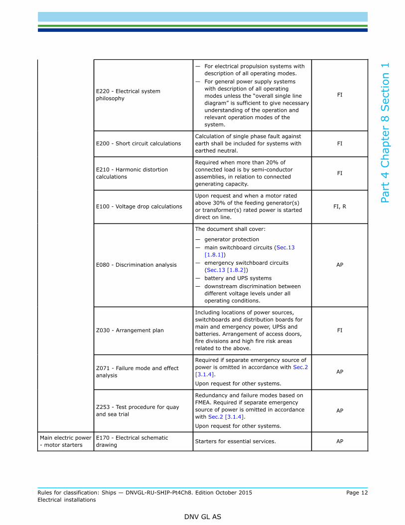
E220 - Electrical systemphilosophy
— For electrical propulsion systems withdescription of all operating modes.
— For general power supply systemswith description of all operatingmodes unless the “overall single linediagram” is sufficient to give necessaryunderstanding of the operation andrelevant operation modes of thesystem.
FI
E200 - Short circuit calculationsCalculation of single phase fault againstearth shall be included for systems withearthed neutral.
FI
E210 - Harmonic distortioncalculations
Required when more than 20% ofconnected load is by semi-conductorassemblies, in relation to connectedgenerating capacity.
FI
E100 - Voltage drop calculations
Upon request and when a motor ratedabove 30% of the feeding generator(s)or transformer(s) rated power is starteddirect on line.
FI, R
E080 - Discrimination analysis
The document shall cover:
— generator protection— main switchboard circuits (Sec.13
[1.8.1])— emergency switchboard circuits
(Sec.13 [1.8.2])— battery and UPS systems— downstream discrimination between
different voltage levels under alloperating conditions.
AP
Z030 - Arrangement plan
Including locations of power sources,switchboards and distribution boards formain and emergency power, UPSs andbatteries. Arrangement of access doors,fire divisions and high fire risk areasrelated to the above.
FI
Z071 - Failure mode and effectanalysis
Required if separate emergency source ofpower is omitted in accordance with Sec.2[3.1.4].
Upon request for other systems.
AP
Z253 - Test procedure for quayand sea trial
Redundancy and failure modes based onFMEA. Required if separate emergencysource of power is omitted in accordancewith Sec.2 [3.1.4].
Upon request for other systems.
AP
Main electric power- motor starters
E170 - Electrical schematicdrawing Starters for essential services. AP

Part
4 C
hapt
er 8
Sec
tion
1
Rules for classification: Ships — DNVGL-RU-SHIP-Pt4Ch8. Edition October 2015 Page 13Electrical installations
DNV GL AS
Main electric power- semi-conductorassemblies
E130 - Electrical datasheet,semiconductor assemblies
For essential services
A DNV GL Type Approval certificateis accepted as an alternative to thedatasheet.
FI
Cables andumbilicals E030 - Cable selection philosophy
Applicable for:
— Vessels following the HSLC— Passenger vessels
AP
Emergency stopsystem
E170 - Electrical schematicdrawing
Emergency stop of electrical propulsionmotors, pumps and fans, showing fail tosafe functionality.
AP
Explosion (EX)protection E090 - Table of Ex-installation Based on approved area classification
drawing and ESD philosophy (if relevant). AP
Hazardous areaclassification
G080 - Hazardous areaclassification drawing
An approved Area classification drawingwhere location of electric equipment inhazardous area is added (Except batteryroom, paint stores and gas bottle store).
FI
Lightingarrangements E190 - Lighting description
Applicable for:
— Vessels following the HSLC— Passenger vessels— Vessels equipped with a bow loading
system
AP
Emergency lights Z030 - Arrangement plan Emergency lighting arrangement AP
2.2.2 Electrical equipment required to be delivered with DNV GL Product Certificate, see Table 3, shall bedocumented as described in Table 2. For equipment covered by a valid DNV GL type approval certificate, thiscertificate may specify exceptions to document approval. Additional documentation will be required if deemednecessary.
Table 2 Component certification, documentation requirements
Object Documentation type Additional descriptionFor approval(AP) or For
information (FI)
Cable E110 - Cable data sheet and design drawing For cables not having a DNVGL type approval. AP
C030 - Detailed drawing
Shafting for electricpropulsion motors andgenerators in mechanicalpropulsion line.
AP
Electricrotatingmachines
C060 - Mechanical component documentation
For permanent magnetmachines only. Relevantdrawings for assessment ofmechanical strength of rotor,permanent magnet fixationand stator core fixation.
AP

Part
4 C
hapt
er 8
Sec
tion
1
Rules for classification: Ships — DNVGL-RU-SHIP-Pt4Ch8. Edition October 2015 Page 14Electrical installations
DNV GL AS
E120 - Electrical data sheet, general FI
E140 - Assembly schedules and technical data AP
E150 - Strength calculation with respect to shortcircuit
When designed sub-transientshort circuit strength exceeds50 kA r.m.s.
FI
E160 - Internal arc withstanding report High voltage assemblies only. FI
E170 - Electrical schematic drawing AP
E180 - Layout of electrical assembly FI
E240 - Functional description for electricalassemblies
When software based controlunits are used. FI
Z252 - Test procedure at manufacturer For high voltage switchgearand controlgear AP
Main- andemergencyswitchboards
Z262 – Report from test at manufacturerFor high voltage switchgearand controlgear. Type testcertificate or report.
FI
E120 - Electrical data sheet, general FI
E140 - Assembly schedules and technical data AP
E150 - Strength calculation with respect to shortcircuit
When designed sub-transientshort circuit strength exceeds50 kA r.m.s.
FI
E160 - Internal arc withstanding report High voltage assemblies only. FI
E170 - Electrical schematic drawing AP
E180 - Layout of electrical assembly FI
E240 - Functional description for electricalassemblies
When software based controlunits are used. FI
Z252 - Test procedure at manufacturer For high voltage switchgearand controlgear AP
Electricalassemblies(Distributionswitchboards,motorstarters,motor controlcentres, etc.)
Z262 – Report from test at manufacturerFor high voltage switchgearand controlgear. Type testcertificate or report.
FI
E120 - Electrical data sheet, general AP
E130 - Electrical data sheet, semiconductorassemblies FI
E140 - Assembly schedules and technical data AP
E180 - Layout of electrical assembly FI
E240 - Functional description for electricalassemblies FI
Semi-conductorassemblies
Z252 - Test procedure at manufacturer AP

Part
4 C
hapt
er 8
Sec
tion
1
Rules for classification: Ships — DNVGL-RU-SHIP-Pt4Ch8. Edition October 2015 Page 15Electrical installations
DNV GL AS
Controlsystem forremote and/or automaticcontrol ofpower system
I200 – Control and monitoring systemdocumentation
AP
Electricalcomponentsbeing certifiedbased onalternativetest methods(i.e.generators,motors,transformers,converters,etc.)
Z252 - Test procedure at manufacturer
Procedure for testingof electrical equipmentdescribing the selectedmethod for testing,measurement andcalculations used forverification in accordancewith the rules requirements.
AP
2.2.3 For general requirements to documentation, see Pt.1 Ch.3 Sec.2.
2.2.4 For a full definition of the documentation types, see Pt.1 Ch.3 Sec.3.
2.3 Equipment certification2.3.1 Required certificates
a) All electrical equipment serving essential or important services shall be delivered with DNV GL Productcertificate and/or DNV GL Type Approval Certificate as required by Table 3.
b) All cables shall be delivered with DNV GL Product certificate or DNV GL Type Approval Certificates asrequired by Table 3. Exempted cables are listed in the note 2 of Table 3. Lightweight cables are onlyaccepted based on a DNV GL Type Approval Certificate.
c) Additional requirements for certification may be given by other relevant parts of the rules.d) Equipment covered by a valid DNV GL Type Approval Certificate is generally accepted without design
assessment, unless otherwise stated in the certificate. A copy of the type approval certificate willsubstitute the required documentation for DNV GL design assessment. A product certificate may beissued based on the DNV GL Type Approval Certificate and a product survey, unless otherwise stated inthe DNV GL Type Approval Certificate.
Guidance note:Type test reports may be requested for important components in d) not having a valid DNV GL Type Approval certificate.Type Approved products have been verified to be suitable for the marine environment.
---e-n-d---of---g-u-i-d-a-n-c-e---n-o-t-e---

Part
4 C
hapt
er 8
Sec
tion
1
Rules for classification: Ships — DNVGL-RU-SHIP-Pt4Ch8. Edition October 2015 Page 16Electrical installations
DNV GL AS
Table 3 Electrical equipment
Additional descriptionObject Certificate
type 1) Issued by Certificationstandard* Continuous rating
Main and Emergencyswitchboard PC Society All
Electrical assemblies(Distributionswitchboards, motorstarters, motor controlcentres, etc.)
PC Society ≥100 kW/kVA
Standardized switchgearunits manufacturedin series with smallerclearance distances thangiven in Sec4 table 1
PC Society ≥100 kW/kVA
Product certification of switchgearwith a smaller clearance distancesthan given in Sec.4 Table 1 shallbe based on the manufacturer’stype test report as required bySec.4 [1.1.8] b).
Generators 3) andtransformers PC Society ≥300 kVA
Generators 3) andtransformers TA Society ≥100 kVA
and <300 kVA
Equipment not having validtype approval certificate may beaccepted on the basis of a DNV GLproduct certificate.
Electric motors 3) PC Society ≥300 kW
Electric motors 3) TA Society >100 kWand <300 kW
Equipment not having validtype approval certificate may beaccepted on the basis of a DNV GLproduct certificate.
Semi-conductorconverters/assemblies formotor drives
PC Society >100 kW
Certification of semi-conductorconverters for motor drives maypartly be based on Type Approvalof power modules.
Semi-conductorconverters/assemblies forpower supply
PC Society >50 kVA
Cables 2) TA Society
Equipment not having validtype approval certificate may beaccepted on the basis of a DNV GLproduct certificate.
For manufactures having typeapproved cables, only routine testsaccording to Sec.9 will be required.
Sealing compound andpacking systems forbulkhead- and deckpenetrations
TA Society For penetrations in fire rated orwater- or gas tight bulkheads.
Busbar trunking systems TA Society

Part
4 C
hapt
er 8
Sec
tion
1
Rules for classification: Ships — DNVGL-RU-SHIP-Pt4Ch8. Edition October 2015 Page 17Electrical installations
DNV GL AS
Cable trays/protectivecasings made of plasticmaterials
TA Society
Control and monitoringsystem - remote and/or automatic control ofpower system
PC Society
When the system includeprotective functions, thesefunctions shall be Type Approvedin accordance with Ch.9. TA ismandatory prior to issuing a PC.
Monitoring-, protection-and management systemsof battery systems
PC Society
*Unless otherwise specified the certification standard is DNV GL Rules.
1) Equipment not having valid type approval certificate may be accepted on the basis of a DNV GL product certificate.2) All cables, except:
a) cables for internal use in electrical assembliesb) short cable lengths on mechanical packagesc) control, automation and communication cables for non-important equipmentd) radio frequency coaxial cables.
3) Certificates for shafts shall be issued as required by Ch.4. This is only applicable for shafts part of the mainmechanical propulsion line.
2.3.2 Product survey
a) A product survey is performed as part of the certification process. The survey normally includes:
— review of the manufacturers documentation— documentation of results from type tests shall, if performed, be available.— visual inspection— testing
b) Visual inspection shall verify that:
— manufacturing and installation is in accordance with the approved design information as required byTable 2
— the product manufacturing is in accordance with the requirements in the relevant equipment sectionof the rules
— general craftsmanship is acceptable.
c) The extent of the manufacturer’s testing shall be as required by applicable sections of the rules. Thetesting shall be performed in accordance with approved test program(s) when required by Table 2. Testresults shall be recorded and filed.
2.4 Onboard survey2.4.1 GeneralOnboard survey shall be performed as part of the classification process, and focuses on the installation onboard as well as on the functionality of the electrical system.
2.4.2 Onboard inspectionsOnboard inspections shall be performed in order to evaluate that:
— the electrical installation is in accordance with the accepted or approved information— the electrical installation is in accordance with the requirements in the rules

Part
4 C
hapt
er 8
Sec
tion
1
Rules for classification: Ships — DNVGL-RU-SHIP-Pt4Ch8. Edition October 2015 Page 18Electrical installations
DNV GL AS
— the craftsmanship is acceptable.
2.4.3 Function testsFunction tests are part of the Society’s verification of the installation’s compliance with the requirements inthe rules and approved documentation.
2.4.4 Available documentationDuring onboard survey, the following documentation shall be available for the Society’s surveyor:
— approved design documentation and documentation submitted for information as required by [2.2]— DNV GL certificates for equipment as required— approved area classification drawing and ESD philosophy where relevant— applicable Ex certificates— manufacturer’s declaration for non-certified equipment that is installed in a hazardous area— additional documentation where deemed necessary to assess the installations' compliance with the rules— cable routing arrangement.

Part
4 C
hapt
er 8
Sec
tion
2
Rules for classification: Ships — DNVGL-RU-SHIP-Pt4Ch8. Edition October 2015 Page 19Electrical installations
DNV GL AS
SECTION 2 SYSTEM DESIGN
1 General
1.1 Design principles1.1.1 General requirements
a) Electrical installations shall be such that the safety of passengers, crew and ship, from electrical hazards,is ensured. (Interpretation of SOLAS Ch. II-1/40.1.3)
b) There shall be two mutually independent electric power supply systems on board:
— main electric power supply system— emergency electric power supply system.
Exceptions are given in [3.1.1] and [3.1.4]. (Interpretation of SOLAS Ch. II-1/40.1.2 and 43.1.1)
c) Services required for normal operation of the vessel shall be operable with the emergency electricalpower generation and distribution system being unavailable, unless mandatory requirements permit suchservices to be powered by emergency electrical power supply only.
d) All consumers that support functions required to be available in normal operation, shall be supplied fromdistribution systems independent of the emergency electrical power supply system. Exemptions aremade for consumers for which mandatory requirements permit emergency power only and for one ofredundant consumers necessary for dead ship recovery.
e) All consumers required to be available in emergency operation shall be supplied from distributionsystems independent of the main electric power supply system.
f) Consumers required having both main and emergency supply shall be supplied as required by relevantrules applicable for these consumers. The primary supply shall be from the main system.
g) Vessels without a dedicated emergency electric power supply system are accepted upon compliance withrequirements in [3.1.4].
Guidance note:Requirements to arrangements of main and emergency power supply systems with respect to fire, flooding or other casualty aregiven in [9.1.2].
---e-n-d---of---g-u-i-d-a-n-c-e---n-o-t-e---
1.1.2 Environmental conditions
a) The electrical installations shall be suitable for operation in those environmental conditions given in Sec.3[2], and have an ingress protection rating as given in Sec.10 [2.2], except as stated in b) and c).
b) Where electrical equipment is installed within environmentally controlled spaces the ambienttemperature for which the equipment shall be suitable may be reduced from 45°C and maintained at avalue not less than 35°C provided:
— the equipment is not for use for emergency services, and shall not be in operation after EmergencyShut-Down (ESD) has been activated
— temperature control is achieved by at least two cooling units so arranged that in the event of lossof one cooling unit, for any reason, the remaining unit(s) is capable of satisfactorily maintaining thedesign temperature
— the equipment can be started in a 45°C ambient temperature and kept in operation until the lesserambient temperature may be achieved
— the cooling equipment shall be rated for a 45°C ambient temperature— malfunction of, or loss of a cooling unit shall be alarmed at a manned control station.

Part
4 C
hapt
er 8
Sec
tion
2
Rules for classification: Ships — DNVGL-RU-SHIP-Pt4Ch8. Edition October 2015 Page 20Electrical installations
DNV GL AS
In accepting a lesser ambient temperature than 45°C, it shall be ensured that electrical cables for theirentire length are adequately rated for the maximum ambient temperature to which they are exposedalong their length.
c) The equipment used for cooling and maintaining the lesser ambient temperature is an important service,in accordance with Sec.13 [1.3.2] and shall comply with the relevant rules.(IACS UR E19)
Guidance note:For the requirements for ventilation and air conditioning, see [9.1.1].
---e-n-d---of---g-u-i-d-a-n-c-e---n-o-t-e---
1.1.3 System earthing
a) System earthing shall be effected by means independent of any earthing arrangements of the non-current-carrying parts.
b) Any earthing impedances shall be connected to the hull. The connection to the hull shall be so arrangedthat any circulating current in the earth connections do not interfere with radio, radar, communicationand control equipment circuits. (IACS UR E11 2.1.4)
c) If the system neutral is connected to earth, suitable disconnecting links or terminals shall be fitted sothat the system earthing may be disconnected for maintenance or insulation resistance measurement.Such means shall be for manual operation only.
d) If the system neutral is connected to earth at several points, equalising currents in the neutral earthingexceeding 20% of the rated current of connected generators or transformers is not acceptable.Transformer neutrals and generator neutrals shall not be simultaneously earthed in the same distributionsystem at same voltage level. On distribution transformers with star connected primary side, the neutralpoint shall not be earthed.
e) In any four wire distribution system the system neutral shall be connected to earth at all times when anyconsumer is connected.
f) Combined PE (protective earth) and N (system earth) is allowed between transformer /generator andN-busbar in first switchboard where the transformer secondary side/generator is terminated i.e. TN-C-S-system. There shall be no connection between the N- and PE-conductor after the PEN-conductor isseparated.
g) In case of earth fault in high voltage systems with earthed neutral, the current shall not be greater thanfull load current of the largest generator on the switchboard or relevant switchboard section and not lessthan three times the minimum current required to operate any earth fault protection relay.
h) Electrical equipment in directly earthed neutral or other neutral earthed systems shall withstand thecurrent due to single phase fault against earth for the time necessary to trip the protection device.
i) It shall be assured that at least one source neutral to ground connection is effective whenever thesystem is in the energised mode. For divided systems, connection of the neutral to the earth shall beprovided for each section.(IACS UR E11 2.1.5 and 2.1.2)
j) For earthing of aluminium superstructures on steel vessels see [9.7].
1.1.4 Types of distribution systems
a) AC power: The following distribution systems can be used (for exemptions see [1.1.5]):
— three-phase three-wire with high-resistance earthed neutral— three-phase three-wire with low-resistance earthed neutral— three-phase three-wire with directly earthed neutral— three-phase three-wire with insulated neutral.
b) In addition for all voltages up to and including 500 V AC:
— three-phase four-wire with neutral earthed, but without hull return— single-phase two-wire with insulated neutral

Part
4 C
hapt
er 8
Sec
tion
2
Rules for classification: Ships — DNVGL-RU-SHIP-Pt4Ch8. Edition October 2015 Page 21Electrical installations
DNV GL AS
— single-phase two-wire with one phase earthed at the power source, but without hull return.
c) DC power: The following distribution systems can be used (for exemptions see [1.1.5]):
— two-wire insulated— two-wire with one pole earthed at the power source (without hull return)— single-wire with hull return as accepted in [1.1.5].
1.1.5 Hull return systems
a) The hull return system of distribution shall not be used, except as stated in b) and c). (Interpretation ofSOLAS Ch. II-1/45.3.1)
b) Provided that any possible resulting current does not flow directly through any gas hazardous spaces,the requirements of a) does not preclude the use of:
— impressed current cathodic protective systems— limited and locally earthed systems— insulation level monitoring devices provided the circulation current does not exceed 30 mA under the
most unfavourable conditions— intrinsically safe circuits.
(Interpretation of SOLAS Ch. II-1/45.3.2)
c) Where the hull return system is used for distribution of DC power, one of the busbars of the distributionboard shall be connected to the hull. Outgoing final sub circuits i.e. all circuits fitted after the lastprotective device shall be with insulated two-wires or two-core cables. (Interpretation of SOLAS Ch.II-1/45.3.3)
1.1.6 Special requirements for non-metallic craft
a) All metal parts of a non-metallic craft shall be bonded together, in so far as possible in consideration ofgalvanic corrosion between dissimilar metals, to form a continuous electrical system, suitable for theearth return of electrical equipment and to connect the craft to the water when water-born. The bondingof isolated components inside the structure is not generally necessary, except in fuel tanks.
b) Each pressure refuelling point shall be provided with a means of bonding the fuelling equipment to thecraft.
c) Metallic pipes capable of generating electrostatic discharges, due to the flow of liquids and gases shall bebonded so they are electrically continuous throughout their length and shall be adequately earthed.
d) Secondary conductors provided for the equalisation of static discharges, bonding of equipment, etc., butnot for carrying lightning discharges shall have a minimum cross section of 5 mm2 copper or equivalentsurge current carrying capacity in aluminium.
e) The electrical resistance between bonded objects and the basic structure shall not exceed 0.02 Ohmexcept where it can be demonstrated that a higher resistance will not cause a hazard. The bonding pathshall have sufficient cross-sectional area to carry the maximum current likely to be imposed on it withoutexcessive voltage drop.
f) A main earth bar shall be defined and fitted at a convenient place on board. This earth bar shall beconnected to a copper plate with a minimum area of 0.25 m2 attached to the hull and so located that it isimmersed under all conditions of heel.
1.2 System voltages and frequency1.2.1 Special requirements for non-metallic craft
a) Electric distribution systems shall operate within the voltage and frequencies given in [1.2.1] to [1.2.7].This also applies to distribution systems where one or more generator prime movers are driving otherequipment. When the main propulsion engine is used as a generator prime mover, variations caused bythe wave motion or sudden manoeuvres including crash stop, shall not exceed the given limitations.

Part
4 C
hapt
er 8
Sec
tion
2
Rules for classification: Ships — DNVGL-RU-SHIP-Pt4Ch8. Edition October 2015 Page 22Electrical installations
DNV GL AS
b) Voltage variations deviating from the standard values are accepted in systems if these are intentionallydesigned for the actual variations.
c) All voltages mentioned are root mean square values unless otherwise stated.
1.2.2 Maximum system voltages
a) Except as stated in b) and c), the following maximum voltages in distribution systems apply:
— connected by permanent wiring: 17 500 V— for portable appliances, which are not hand-held during operation, and with connection by flexible
cable and socket outlet: 1000 V— supply for lighting (including signal lamps), space heaters in accommodation spaces, and hand-held
portable appliances: 250 V. Phase voltage of a system with neutral earthed may be used for thispurpose.
b) For High Speed, Light Craft and Naval Surface Craft, the maximum distribution voltage is limited to500 V, except for crafts with electric propulsion systems, where higher voltages are accepted.
c) Where necessary for special application, higher voltages may be accepted by the Society.(IACS UR E11 1.2)
1.2.3 Maximum control voltagesFor control equipment being a part of power and heating installations (e.g. pressure or temperatureswitches for start and stop of motors), the maximum voltage is 1000 V. However, control voltage to externalequipment shall not exceed 500 V.
1.2.4 Supply voltage variations
a) Electric AC distribution systems shall be designed and installed so that the voltage variations on mainswitchboards are maintained within these limits:
— Steady state
±2.5% of nominal AC system voltage.
— Transient statefrom −15% to +20% of nominal AC voltage.
b) Electric DC battery powered systems shall be designed and installed so that the voltage variations on themain distribution board are maintained within these limits:
— Voltage tolerance:-12% to +30% of nominal DC system voltage
— Voltage cyclic variation:
max 5%
— Voltage ripple:
max 10%.
c) The requirement for maximum transient voltage shall also be complied with in case of load sheddingor tripping of consumers. The requirement for maximum transient voltage is not applicable to failureconditions.
d) After a transient condition has been initiated, the voltage in a main distribution AC system shall not differfrom nominal system voltage by more than ±3% within 1.5 s. In an emergency distribution system thevoltage shall not differ from nominal system voltage by more than ±4% within 5 s.
e) In AC installations designed for variable system voltage, equipment and its protection devices shall berated to operate within the design limits throughout the voltage range.

Part
4 C
hapt
er 8
Sec
tion
2
Rules for classification: Ships — DNVGL-RU-SHIP-Pt4Ch8. Edition October 2015 Page 23Electrical installations
DNV GL AS
1.2.5 Voltage variations in the distribution system
a) An AC distribution system shall be designed and installed so that the stationary voltage drop in supply toindividual consumers, measured from the main switchboard to the consumer terminals does not exceed6% of system nominal voltage.
b) A DC distribution system shall be designed and installed so that the stationary voltage variation insupply to individual consumers, measured from the battery distribution to the consumer terminals, doesnot exceed ±10% of system nominal voltage. Voltage ripple and cyclic variation deviation as stated in[1.2.4].
c) Specific requirements for transient voltages on consumer terminals during start or stop are not given.However, the system shall be designed so that all consumers function satisfactorily.
1.2.6 System frequency
a) The frequency variations in AC installations with fixed nominal frequency shall be kept within thefollowing limits:
— 95 to 105% of rated frequency under steady load conditions— 90 to 110% of rated frequency under transient load conditions.
b) In AC installations designed for variable system frequency, equipment and its protection devices shall berated to operate within the design limits throughout the frequency range.
Guidance note:See Ch.3 regarding the prime movers' speed governor characteristics.
---e-n-d---of---g-u-i-d-a-n-c-e---n-o-t-e---
1.2.7 Harmonic distortion
a) Equipment producing transient voltage, frequency and current variations shall not cause malfunction ofother equipment on board, neither by conduction, induction or radiation.
b) In distribution systems the acceptance limits for voltage harmonic distortion shall correspond to IEC61000-2-4 Class 2. In addition, no single order harmonic shall exceed 5%.
Guidance note:IEC 61000-2-4 Class 2 implies that the total voltage harmonic distortion shall not exceed 8%.
---e-n-d---of---g-u-i-d-a-n-c-e---n-o-t-e---
c) The total harmonic distortion may exceed the values given in b) under the condition that all consumersand distribution equipment subjected to the increased distortion level have been designed to withstandthe actual levels. The system and components ability to withstand the actual levels shall be documented.
d) When filters are used for limitation of harmonic distortion, special precautions shall be taken so that loadshedding or tripping of consumers, or phase back of converters, do not cause transient voltages in thesystem in excess of the requirements in [1.2.4]. The generators shall operate within their design limitsalso with capacitive loading. The distribution system shall operate within its design limits, also whenparts of the filters are tripped, or when the configuration of the system changes.
Guidance note:The following effects should be considered when designing for higher harmonic distortion, refer to c):
— additional heat losses in machines, transformers, coils of switchgear and controlgear
— additional heat losses in capacitors for example in compensated fluorescent lighting
— resonance effects in the network
— functioning of instruments and control systems subjected to the distortion
— distortion of the accuracy of measuring instruments and protective gear (relays)
— interference of electronic equipment of all kinds, for example regulators, communication and control systems, position- findingsystems, radar and navigation systems.
A declaration or guarantee from system responsible may be an acceptable level of documentation.
---e-n-d---of---g-u-i-d-a-n-c-e---n-o-t-e---

Part
4 C
hapt
er 8
Sec
tion
2
Rules for classification: Ships — DNVGL-RU-SHIP-Pt4Ch8. Edition October 2015 Page 24Electrical installations
DNV GL AS
2 Main Electric Power Supply System
2.1 General2.1.1 Capacity
a) The main power supply system shall have the capacity to supply power to all services necessaryfor maintaining the ship in normal operation without recourse to the emergency source of power.(Interpretation of SOLAS Ch. II-1/40.1.1)
b) There shall be component redundancy for main sources of power, transformers and power converters inthe main power supply system so that with any source, transformer or power converter out of operation,the power supply system shall be capable of supplying power to the following services:
— those services necessary to provide normal operational conditions for propulsion and safety— starting the largest essential or important electric motor on board, except auxiliary thrusters, without
the transient voltage and frequency variations exceeding the limits specified in [1.2]— ensuring minimum comfortable conditions of habitability which shall include at least adequate
services for cooking, heating, domestic refrigeration (except refrigerators for air conditioning),mechanical ventilation, sanitary and fresh water
— for a duplicated essential or important auxiliary, one being supplied non-electrically and the otherelectrically (e.g. lubricating oil pump No. 1 driven by the main engine, No. 2 by electric motor), it isnot expected that the electrically driven auxiliary is used when one generator is out of service
— For dead ship recovery, see [2.2.4].
(Interpretation of SOLAS Ch. II-1/41.1)Guidance note:Those services necessary to provide normal operational conditions of propulsion and safety do not normally include services such as:
— thrusters not forming part of the main propulsion or steering
— mooring
— cargo handling gear
— refrigerators for air conditioning.
— ballast water treatment system
However, additional services required by a class notation will be added to the list of important services.In regard to non-important load, the capacity of all generators can be taken into consideration.
---e-n-d---of---g-u-i-d-a-n-c-e---n-o-t-e---
2.1.2 Generator prime movers
a) Each generator required according to [2.1.1] shall normally be driven by a separate prime mover, i.e.each generator shall be driven by one engine, and one engine shall only drive one generator.
b) If a prime mover for a generator is also used for driving other auxiliary machinery in such a way that itis physically possible to overload the engine, an interlock or other effective means for preventing suchoverloading shall be arranged. The availability of the generator shall be at least as for separately drivengenerators.
c) When generators driven by reciprocating steam engines or steam turbines are used, and the operationof the boiler(s) depends on electric power supply, there shall be at least one generator driven by anauxiliary diesel engine or gas turbine on board, enabling the boiler plant to be started.
d) A generator or generator system, having the ship's main propulsion machinery as its prime mover, maybe accepted as a main source of electrical power, provided that it can be used in all weather conditionsand operating modes for the vessel, including standstill of propeller.
e) There shall be at least one generator driven by a separate prime mover. The capacity of separatelydriven generators shall be sufficient to supply all essential and important services that can be expected

Part
4 C
hapt
er 8
Sec
tion
2
Rules for classification: Ships — DNVGL-RU-SHIP-Pt4Ch8. Edition October 2015 Page 25Electrical installations
DNV GL AS
to be simultaneously in use, regardless of the operational mode of the vessel, including stopped.This shall be possible without utilising any emergency power source. (Interpretation of SOLAS Ch.II-1/41.1.3)
f) Shaft generator installations which do not comply with the requirement given in d), may be fitted asadditional source(s) of power provided that:
— on loss of the shaft generator(s) or upon frequency variations exceeding ±10%, a standby generatingset is automatically started and connected to the main switchboard. Synchronisation shall be possiblewithin frequency variations of ±10%.
— the capacity of the standby set is sufficient for the loads necessary for propulsion and safety of thevessel.
g) Generator prime movers shall comply with the requirements in Ch.2 Sec.4.Guidance note:Shaft generators and generators based on variable speed drives will be evaluated in each case. As a minimum, the following shouldbe evaluated:
— availability in all operating modes
— stability of output voltage and frequency
— short circuit capability and protection
— auxiliary systems, e.g. ventilation, cooling system, and control power distribution.
---e-n-d---of---g-u-i-d-a-n-c-e---n-o-t-e---
2.2 System functionality2.2.1 Start of generator setsAt least two generator sets, connected to separate main busbar sections, shall be arranged with systems forstarting in a blackout situation. However, only one standby generator may be permitted if this generator isnot intended to be used for normal operation of the ship.
2.2.2 Energy for starting
a) The energy used for starting in a blackout situation shall be arranged as required in [5.1].b) Control power supply to electronic governors, automatic volatge regulators (AVRs) and necessary control
power for auxiliary engines shall, if dependent on external power, be arranged as required for startingarrangement in [5.1.2].
c) Where prime movers and/or generators arranged as standby generators depend upon auxiliarymachinery systems being available in a blackout situation, these auxiliaries shall be arranged with atleast two independent sources of power. At least one of the sources of power shall be from stored energylocated within the engine room. The capacity of the power sources shall correspond to the requirednumber of starting attempts and/or last for at least 30 minutes.
d) Where prime movers and/or generators arranged as standby generators depend upon auxiliarymachinery systems during standby mode in order to start in a blackout situation, auxiliaries for at leastone generator shall be supplied from the main switchboard in order to comply with [1.1.1].
e) When a single, dedicated, standby generator is used, this generator set alone shall be arranged inaccordance with this paragraph, i.e. two sources of energy for starting, control power and auxiliaries. Asabove, one of the sources for auxiliaries shall be from stored energy located within the machinery space.
Guidance note:Example of auxiliary system that must be available in a blackout situation may be fuel oil booster pump, and lubrication oil pumpif start blocking is activated within 30 minutes after blackout.Example of auxiliary system that must be supplied in standby mode may be pre lubrication pump and jacket water heating.
---e-n-d---of---g-u-i-d-a-n-c-e---n-o-t-e---

Part
4 C
hapt
er 8
Sec
tion
2
Rules for classification: Ships — DNVGL-RU-SHIP-Pt4Ch8. Edition October 2015 Page 26Electrical installations
DNV GL AS
2.2.3 Load shedding and automatic restoration of powerWhere electrical power is necessary for propulsion and steering of the ship, the system shall be so arrangedthat the electrical supply to equipment necessary for propulsion and steering, and to ensure safety of thevessel, will be maintained or immediately restored in case of loss of any one of the generators in service.This means:
— The power system shall be equipped with automatic load shedding or other automatic means to preventsustained overload of any generator, ref. [7.1.1].
— Upon loss of power, provision shall be made for automatic starting and connecting to the mainswitchboard of standby generator(s) of sufficient capacity, and automatic restarting of the essentialauxiliaries, in sequential operation if required. Starting and connection to the main switchboard of thestandby generator is to be preferably within 30 seconds, but in any case not more than 45 seconds, afterloss of power. Either restart of the previous running auxiliary, or start of a standby auxiliary system isaccepted.
— Where prime movers with longer starting time are used, this starting and connection time may beexceeded upon approval from the society.
— Where several generator units in parallel operation are required to cover the ship's power supply,the failure of one of the units shall cause the immediate trip of non-important equipment and, wherenecessary, the important equipment, where this is the only way to ensure that the remaining units cansupply the essential equipment. Load reduction may be one solution to achieve this.
(Interpretation of SOLAS Ch.II-1/41.5.1.1)
2.2.4 Start from dead ship
a) The requirement for start from dead ship is given in Ch.1 in the Rules for Classification of Ships.b) In addition, the generating sets shall be such as to ensure that with any one generator, transformer or
power converter out of service, the remaining generating sets, transformers and power converters shallbe capable of providing the electrical services necessary to start the main propulsion plant from a deadship condition. The emergency source of electrical power may be used for the purpose of starting froma dead ship condition if its capability either alone or combined with that of any other source of electricalpower is sufficient to provide at the same time those services required to be supplied by [3.1.3], exceptfire pumps and steering gear, if any.
Guidance note:On installations without a dedicated emergency generator in accordance with [3.1.4], only one engine room is considered to be indead ship conditions, since there should be redundancy in starting arrangement for each engine room as required for emergencygenerator sets. However, necessary energy for auxiliaries needed for start (fuel, lubrication oil priming, etc.) must have the samearrangement as the source for starting energy.For vessels with two or more independent engine rooms but not complying with [3.1.4], the requirements for dead ship startingstill applies, i.e. dead ship condition in both/all engine rooms simultaneously. Necessary energy for auxiliaries needed for start (fuel,lubrication oil priming, etc.) must have the same arrangement as the source for starting energyIn cases where only electric starting is arranged for engines driving generators and the main propulsion engines, an additional batteryfor “dead ship” starting may be installed. This battery shall then be dedicated for this purpose and always kept fully charged andmonitored.
---e-n-d---of---g-u-i-d-a-n-c-e---n-o-t-e---
2.2.5 RegenerationRegenerated power caused by e.g. water milling of propellers shall not cause any alarms, neither in plannedoperating modes nor during emergency manoeuvres. Where necessary, braking resistors for absorbing orlimiting such energy shall be provided.

Part
4 C
hapt
er 8
Sec
tion
2
Rules for classification: Ships — DNVGL-RU-SHIP-Pt4Ch8. Edition October 2015 Page 27Electrical installations
DNV GL AS
3 Emergency Power Supply System
3.1 General3.1.1 Emergency power source
a) A self-contained emergency source of electrical power shall be provided.b) The emergency source of power, associated transforming equipment, emergency switchboard,
emergency lighting switchboard and transitional source of emergency power shall be located above theuppermost continuous deck and be readily accessible from open deck. It shall not be located forward ofthe collision bulkhead. (Interpretation of SOLAS Ch. II-1/43.1.2).
c) The emergency source of electrical power may be either a generator or an accumulator battery.(Interpretation of SOLAS Ch. II-1/43.3).
d) The emergency source of power shall be automatically connected to the emergency switchboard in caseof failure of the main source of electric power. If the power source is a generator, it shall be automaticallystarted and within 45 s supply at least the services required to be supplied by transitional power as listedin Table 1. (Interpretation of SOLAS Ch. II-1/43.3.1.2, 43.3.2.2 and 43.3.2.3).
e) Ventilation of the space containing the emergency source of electrical power or ventilators for radiator ofemergency generator engine, shall comply with the requirements in Pt.3 Ch.12 Sec.9 [5] and it shall notbe necessary with any closing arrangement. If any closing arrangements are installed, they shall fail toopen position.
f) Cooling arrangement for the emergency source of power, e.g. pipes, pumps and heat exchangers, shallbe located in the same space as the emergency generator. Heat exchangers may be accepted outside, inclose vicinity to the emergency source of power.
g) If the emergency source of power is not automatically connected to the emergency switchboard,a transitional source of emergency electrical power, suitably located for use in an emergency, withsufficient capacity of supplying the consumers listed in Table 1, may be accepted. (Interpretation ofSOLAS Ch. II-1/43.3.1.3).
h) The emergency source of power shall not be used for supplying power during normal operation of thevessel. Exceptionally, and for short periods, the emergency source of power may be used for blackoutsituations, starting from dead ship, short term parallel operation with the main source of electrical powerfor the purpose of load transfer and for routine testing of the emergency source of power.(Interpretation of SOLAS Reg. II-1/43.3.1.3).Exception for high speed light craftFor a craft applying the HSC Code, location of emergency supply system below uppermost continuousdeck may be accepted provided easy access from a normally manned area. However, the emergencysource of power shall always be located above worst damage waterline.Exception for shipsThe requirement for emergency source of power applies to all cargo vessels with the followingexemptions:
— ships with one of the service restrictions notations R2, R3 and R4— ships of less than 500 gross tonnage— fishing vessels less than 24 m.
Guidance note:Concerning requirements for an emergency generator, see [3.3].Concerning requirements for a transitional source of emergency electrical power, see [3.2].
---e-n-d---of---g-u-i-d-a-n-c-e---n-o-t-e---

Part
4 C
hapt
er 8
Sec
tion
2
Rules for classification: Ships — DNVGL-RU-SHIP-Pt4Ch8. Edition October 2015 Page 28Electrical installations
DNV GL AS
3.1.2 Capacity
a) The electrical power available shall be sufficient to supply all services essential for safety in anemergency, due regard being paid to such services as may have to be operated simultaneously, alsotaking into account starting currents and transitory nature of certain loads. (Interpretation of SOLAS Ch.II-1/43.2)
b) Where the emergency source of electrical power is an accumulator battery it shall be capable of carryingthe emergency electrical load without recharging while maintaining the voltage of the battery as requiredby [1.2]. (Interpretation of SOLAS Ch. II-1/43.3.2.1)
c) When non-emergency consumers are supplied by the emergency source of power, it shall eitherbe possible to supply all consumers simultaneously, or automatic disconnection of non-emergencyconsumers upon start of the generator shall be arranged. The system shall be so arranged that thelargest consumer connected to the emergency power supply system can be started at all times withoutoverloading the generator unless automatically disconnected upon start of the emergency generator.(Interpretation of SOLAS Ch. II-1/43.5.5)
d) Starting air compressors, preheaters and lubrication oil pumps for the main engine or auxiliary enginesmay be equipped for automatic disconnection from the emergency switchboard. Such consumersnecessary for starting from dead ship, if supplied from the emergency source of power, shall be possibleto connect manually at the emergency switchboard also when the emergency generator is running. Ifthey may cause overloading of the emergency generator, warning signs shall be fitted also stating theload of the consumers.
Guidance note:The emergency generator rating shall be based upon the consumed power for all consumers that may be in simultaneous operation.Non-emergency motors, which will not automatically start, are considered to be automatically disconnected.
---e-n-d---of---g-u-i-d-a-n-c-e---n-o-t-e---
3.1.3 Services to be supplied
a) For High Speed and Light Craft see Rules for Classification of HSLC HSLC Pt.5b) For additional class notations, additional requirements may apply.c) For ships the list of services in Table 1 shall be supplied by an emergency source of power and by a
transitional source of power, if any, for the period listed.d) For a ship engaged regularly in voyages of short duration, a period shorter than the 18 hour period
specified in Table 1 may be accepted, but not less than 12 hours. (Interpretation of SOLAS Ch.II-1/43.2.6.2)
e) The emergency source of electrical power shall be capable of supplying simultaneously at least theservices listed in Table 1 for the periods specified, if they depend upon an electrical source for theiroperation. (Interpretation of SOLAS Ch. II-1/43.2.1 to 43.2.6.1)
f) For fishing vessels the following services shall be supplied for a period of 3 hours for vessels below 45 mand 8 hours for vessels of 45 m and above:
— VHF radio installation as required by Torremolinos Convention reg. IX/6(1)(a) and (b)— Internal communication equipment— Fire detecting system— Signals which may be required in an emergency— Navigation lights if solely electrical— Emergency lighting:
— of launching stations and over side of the vessel— in all alleyways, stairways and exits— in spaces containing machinery or the emergency source of power— in control station— in fish handling and fish processing space
— Electrical driven emergency fire pump if any.

Part
4 C
hapt
er 8
Sec
tion
2
Rules for classification: Ships — DNVGL-RU-SHIP-Pt4Ch8. Edition October 2015 Page 29Electrical installations
DNV GL AS
If applicable:
— The MF radio installation required by Torremolinos Convention IX/8(1)(a) and (b) and reg. IX/9(1)(b)and (c)
— The ship earth station required by Torremolinos Convention regulation IX/9(1)(a)— MF/HF radio installation required by Torremolinos Convention IX/9(2)(a) and (b) and reg. IX/10(1).
Table 1 Services to be supplied by an emergency source and by a transitional source, includingrequired duration for main class
Service Emergency power consumers in shipsDuration of
emergency power,
(h)
Duration oftransitional power 4),
(h)
At every muster and embarkation station, for survivalcraft and their launching appliances, and at the area ofwater into which it shall be launched.
3 0.5 2)
In all service and accommodation alleyways, stairwaysand exits, personnel lift cars and personnel lift trunks. 18 0.5 2)
In the machinery spaces and main generating stationsincluding their control positions. 18 0.5 2)
In all control stations, machinery control rooms,steering gear and at each main and emergencyswitchboard.
18 0.5 2)
At all stowage positions for firemen's outfits. 18 0.5 2)
At the fire pump referred to in this table and itsstarting position. 18 0.5 2)
At the sprinkler pump and its starting position, if any. 18 0.5 2)
At the emergency bilge pump and its starting position,if any. 18 0.5 2)
Emergency lighting
In all cargo pump-rooms of tankers 18 0.5 2)
Navigation lightsThe navigation lights and other lights required by theInternational Regulations for Preventing Collisions atSea in force.
18 0.5 2)
Fire pumps
One of the fire pumps required by SOLAS Ch.II-10.2.2 (Ch.11 of the Rules for Classification ofShips) if dependent upon the emergency generator forits source of power. (SOLAS Ch. II-1/43.2.5)
18
Firefightingsystems, e.g. totalflooding systems
Firefighting systems required to be supplied byemergency power in accordance with relevant IMOregulations.
0.5
Steering gear
The steering gear if required to be so supplied byCh.10. (SOLAS Ch. II-1/43.2.6.1)
(For a ship of less than 10 000 gross tonnage theduration shall be at least 10 minutes.)
0.5
Watertight doorsand hatches
The power, control and indicators for watertight doorsand hatches. 0.5 0.5 2)

Part
4 C
hapt
er 8
Sec
tion
2
Rules for classification: Ships — DNVGL-RU-SHIP-Pt4Ch8. Edition October 2015 Page 30Electrical installations
DNV GL AS
Life boat Second means of launching of free fall life boat, ref.LSA Code.
6)
Stabilisers (if any)
Means to bring the stabiliser wings inboard andindicators on the navigating bridge to show theposition of the stabiliser wings if there is a dangerof the survival craft being damaged by the ship'sstabiliser wings (as required by Pt.3 Ch.3 Sec.9of theRules for Classification of Ships)
- -
The VHF radio installation required by SOLAS Ch.IV/7.1.1 and IV/7.1.2. 18
If applicable:
the MF radio installation required by SOLAS Ch.’sIV/9.1.1, IV/9.1.2, IV/10.1.2 and IV/10.1.3
the ship earth station required by regulation IV/10.1.1
the MF/HF radio installation required by regulationsIV/10.2.1, IV/10.2.2, IV/10.1.2 and IV/11.1.
18
All internal communication equipment, as required, inan emergency; shall include:
means of communication between the navigatingbridge and the steering gear compartment
means of communication between the navigatingbridge and the position in the machinery space orcontrol room from which the engines are normallycontrolled
means of communication between the bridge and thepositions fitted with facilities for operation of radioequipment.
18 1) 0.5 2)
Communication 3)
Intermittent operation of the daylight signallinglamp, the ship's whistle, the manually operated callpoints, and all internal signals that are required in anemergency.
18 1) 0.5 2)
Navigation
Navigation equipment as required by statutoryrequirements.
For ships seeking compliance with NAUT(OSV), seePt.6 Ch.3.
18 1)
The fire detection and alarm systems. 18 1) 0.5 2)
Power supply to the alarm sounder system when notan integral part of the detection system 7) 18 1) 7)
The gas detection and alarm systems 18 1) 0.5 2)Alarm systems 5)
The general alarm system. 18 1) 0.5 2)

Part
4 C
hapt
er 8
Sec
tion
2
Rules for classification: Ships — DNVGL-RU-SHIP-Pt4Ch8. Edition October 2015 Page 31Electrical installations
DNV GL AS
1) Unless such services have an independent supply for the period of 18 hours from an accumulator battery suitablylocated for use in an emergency.
2) Unless such equipment has an automatically charged battery with adequate capacity, suitably located for use in anemergency.
3) Means of communication according to relevant SOLAS requirements and DNV GL Statutory Interpretations apply formandatory internal communications systems.
4) A transitional source of power is required for:
— vessels where the emergency source of power is not automatically connected to the emergency switchboardwithin 45 s
— class notationsPassenger ship, and Ferry.
5) Only when the service or function is required by other applicable rules.
6) Power for launching of the life boat shall be available on demand with duration of 10 minutes for each lifeboat.
7) The alarm sounder system utilised by the Fixed Fire Detection and Fire Alarm System shall be powered from noless than two sources of power, one of which shall be an emergency source of power. In vessels required by SOLASregulation II-1/42 or 43 to be provided with a transitional source of emergency electrical power the alarm soundersystem shall also be supplied from this power source. (IACS SC35)
3.1.4 Independent installation of power sourcesWhen the IMO HSC Code is applicable, or when alternative emergency power arrangement has beenaccepted by the authorities of the flag state the following may apply:Where the main source of electrical power is located in two or more spaces which have their own systems,including power distribution and control systems, completely independent of the systems in the other spacesand such that a fire or other casualty in any one space will not affect the power distribution from the others,or to the services in Table 1, the requirements for self-contained emergency power source may be consideredsatisfied without an additional emergency source of electrical power, provided that:
1) There are at least two generator sets meeting the inclination design requirements for emergencyinstallations in Sec.3 [2.1.1].
2) Each set has capacity to meet the requirements in item [3.1.2].3) These generator sets are located in each of at least two spaces.4) A casualty in any one space will not affect the control system for automatic start and connection of both/
all these generator sets.5) Power to all required emergency services, as listed in Table 1 are to be automatically available within
45 seconds when power is automatically restored after a black-out, including those supplied from maindistribution systems. (These consumers may be supplied from main switchboards or sub distributionboards).
6) Load shedding/trip is arranged to prevent overload of these generator sets.7) Transitional source of power is installed when required in [3.2.1].8) The location of each of the spaces referred to in this paragraph is such that one of these generator sets
remains operable and readily accessible in the final condition of damage. Further, the boundaries shallmeet the provisions of [9.1.2], except that contiguous boundaries shall consist of an A-60 bulkhead anda cofferdam or a steel bulkhead insulated to class A-60 on both sides.
9) Bus tie breakers between the spaces have short circuit protection providing discrimination.10) The arrangements of these generating sets comply with the requirements given in:
— [3.1.5] c), i.e. bus-tie breakers shall open automatically upon blackout— [3.1.5] h)— [3.3.1]— [3.3.3] (see guidance note).
Guidance note:

Part
4 C
hapt
er 8
Sec
tion
2
Rules for classification: Ships — DNVGL-RU-SHIP-Pt4Ch8. Edition October 2015 Page 32Electrical installations
DNV GL AS
1) The second source of energy for starting may be located outside the machinery space. In case of a fire or other casualty inany one space a total of at least two sources of starting energy for the remaining generator(s) have to be available.
2) The system philosophy for the electrical power supply system should describe how this paragraph is complied with. Inaddition it should include description of physical location of main components and cable routings. The test program foronboard testing should describe in detail how this functionality shall be tested.
3) A vessel built in accordance with this paragraph will not have any dedicated emergency power system, since the two (ormore) independent main power systems are considered to ensure power supply to emergency consumers at all times.Compliance with [3.3.2] is not required.
---e-n-d---of---g-u-i-d-a-n-c-e---n-o-t-e---
3.1.5 Emergency switchboard
a) The emergency switchboard shall be installed as near as is practicable to the emergency source ofelectrical power. (Interpretation of SOLAS Ch. II-1/43.5.1)
b) Where the emergency source of electrical power is a generator, the emergency switchboard, theemergency transformers (if any) and the emergency lighting switchboard shall be located in the samespace unless the operation of the emergency switchboard would thereby be impaired. (Interpretation ofSOLAS Ch. II-1/43.5.2)
c) In normal operation, the emergency switchboard shall be supplied from the main switchboard by aninterconnecting feeder. This feeder shall be protected against overload and short circuit at the mainswitchboard, and shall be disconnected automatically at the emergency switchboard upon failure of thesupply from the main source of electrical power. (Interpretation of SOLAS Ch. II-1/43.5.4)
d) Where the emergency switchboard is arranged for the supply of power back to the main distributionsystem, the interconnecting cable shall, at the emergency switchboard end, be equipped with switchgearsuitable for at least short circuit protection.
e) The emergency switchboard and emergency distribution boards shall not be considered as part of themain distribution system, even though supplied from such during normal operation.
f) Technical requirements for functionality and construction for main switchboards, apply to emergencyswitchboards.
g) Provision shall be made for the periodic testing of the complete emergency system and shall include thetesting of automatic starting arrangements. (Interpretation of SOLAS Ch. II-1/43.7)
h) No accumulator batteries, except the starting battery for the emergency generator prime mover andcontrol and monitoring for the emergency system, shall be installed in the same space as the emergencyswitchboard. (Interpretation of SOLAS Ch. II-1/43.5.3)
i) Cables between equipment installed in the emergency generator room, shall be run inside the boundaryof the room.
Guidance note:It is accepted that there are dividing bulkheads within the A60 boundary of the emergency generator space provided that there isaccess through the dividing bulkheads.
---e-n-d---of---g-u-i-d-a-n-c-e---n-o-t-e---
3.2 Transitional source3.2.1 Transitional source of emergency electrical power
a) A transitional source of power is required where the emergency source of power is not arranged forautomatic connection to the emergency switchboard within 45 s, or if required by other applicable rules,e.g. class notation Passenger ship, or Ferry.
b) The transitional source of electrical power shall consist of an accumulator battery suitably located foruse in an emergency as required for emergency power in [3.1.1], unless it supplies power to consumerswithin the same space as the transitional source itself.
c) The battery source shall be charged by the emergency power distribution system and be able to operate,without recharging, while maintaining the voltage of the battery throughout the discharge period as

Part
4 C
hapt
er 8
Sec
tion
2
Rules for classification: Ships — DNVGL-RU-SHIP-Pt4Ch8. Edition October 2015 Page 33Electrical installations
DNV GL AS
required by [1.2]. The battery capacity shall be sufficient to supply automatically, in case of failure ofeither the main or the emergency source of electrical power, for the duration specified, at least theservices required by Table 1, if they depend upon an electrical source for their operation. See notes toTable 1.(Interpretation of SOLAS Ch. II-1/43.4)
3.3 Emergency generators3.3.1 Prime mover for emergency generator
a) Where the emergency source of electrical power is a generator, it shall be driven by a suitable primemover having independent supply of fuel with a flashpoint (closed cup) of not less than 43°C and shallhave auxiliary systems e.g. cooling system, ventilation and lubrication operating independently of themain electrical power system. (Interpretation of SOLAS Ch. II-1/43.3.1.1)
b) The prime mover shall be started automatically upon failure of the main source of electrical powersupply. (Interpretation of SOLAS Ch. II-1/43.3.1.2)
c) Where automatic start of the emergency generator is required and the emergency source of power is notready for immediate starting, an indication shall be given in the engine control room.
3.3.2 Protective functions of emergency generating sets
a) The protective shutdown functions associated with emergency generating sets shall be limited to thosenecessary to prevent immediate machinery breakdowns i.e. short circuit. If overcurrent protectionrelease is implementd, the setting of this release shall be so high that under no circumstances the supplyto emergency consumers is impaired. For prime mover, see Ch.3 Sec.1.
b) Generator circuit breaker shall have undervoltage release with a time delay longer than the respectiveshort circuit time delay and clearance time.
c) A shut down or stop signal to the prime mover shall cause disconnection signal to the generator circuitbreaker if a generator runs in parallel with any other source of power.
d) Other protective functions such as overcurrent, high temperature etc. shall, if installed, give alarm only.It is recommended that such alarms are given to the main alarm system.
e) For use as a harbour generator, see [3.3.4].
3.3.3 Starting arrangements for emergency generating sets
a) An emergency generating set shall be capable of being readily started in its cold condition at atemperature of 0ºC. If this is impracticable, or the vessel is intended for operation at lower ambienttemperatures, provisions shall be made for heating arrangements to ensure ready starting of thegenerating sets. (Interpretation of SOLAS Ch. II-1/44.1)
b) Emergency generating set shall be equipped with starting device with a stored energy capability of atleast three consecutive starts. A second source of energy shall be provided for an additional three startswithin 30 minutes, unless manual starting can be demonstrated to be effective within this time. Onestarting motor is sufficient. The duration of each starting attempt shall be minimum 10 s. (Interpretationof SOLAS Ch. II-1/44.2)
c) Stored energy for starting shall be maintained at all times, and shall be powered from the emergencyswitchboard. All starting, charging and energy storing devices shall be located in the emergencygenerator space. Compressed air starting systems may however be maintained by the main or auxiliarycompressed air system through a suitable non-return valve fitted in the emergency generator space.(Interpretation of SOLAS Ch. II-1/44.3)
d) If accumulator batteries are used for starting of the emergency generator prime mover, every such primemover shall have separate batteries that are not used for any purpose other than the operation of theemergency generating set.
e) If the emergency generator set is equipped with an electronic governor, electronic AVR, priming pumpsor other auxiliaries dependent upon electric power supply for a successful start, two independent sourcesof power, located in the same space as the emergency source of power, shall be provided.

Part
4 C
hapt
er 8
Sec
tion
2
Rules for classification: Ships — DNVGL-RU-SHIP-Pt4Ch8. Edition October 2015 Page 34Electrical installations
DNV GL AS
3.3.4 Emergency generator used in port
a) The emergency source of power may be used during time in port for the supply of the ship's mainelectrical system, provided the requirements for available emergency power is adhered to at all times.
b) To prevent the generator or its prime mover from becoming overloaded when used in port, arrangementsshall be provided to shed sufficient non-emergency loads to ensure its continued safe operation.
c) The prime mover shall be arranged with fuel oil filters and lubrication oil filters, monitoring equipmentand protection devices as required for the prime mover for main power generation and for unattendedoperation.
d) The fuel oil supply tank to the prime mover shall be provided with a low level alarm, arranged at a levelensuring sufficient fuel oil capacity for the emergency services for the required period.
e) Fire detectors shall be installed in the location where the emergency generator set and emergencyswitchboard are installed.
f) Means shall be provided to readily change over to emergency operation.g) Control, monitoring and supply circuits, for the purpose of the use of the emergency generator in port
shall be so arranged and protected that any electrical fault will not influence the operation of the mainand emergency services. When necessary for safe operation, the emergency switchboard shall be fittedwith switches to isolate the circuits.
h) Instructions shall be provided on board to ensure that when the vessel is under way all control devices(e.g. valves, switches) are in a correct position for the independent emergency operation of theemergency generator set and emergency switchboard. These instructions are also to contain informationon required fuel oil tank level, position of harbour or sea mode switch if fitted, ventilation openings etc.
4 Battery Systems
4.1 General4.1.1 Capacity of accumulator batteriesBatteries that shall be used for power supply required by these rules shall be dimensioned for the timerequired for the intended function at an ambient temperature of 0°C, unless heating is provided.
4.1.2 Battery powered systems
a) Every battery system shall have its own dedicated charging device (I.E. in order to constitute a batterysystem).
b) Battery systems shall be so rated that they can supply the consumers for the required period, inaccordance with the energy balance, when charged to 80 % of their rated capacity.
c) Each charging device is, at least, to have sufficient rating for recharging to 80% of rated batterycapacity, within 10 hours, while the system has normal load.
d) The battery charger shall be suitable to keep the battery in full charged condition, (float charge), takinginto account battery characteristics, temperature and load variations. If the battery requires specialvoltage regulation to obtain effective recharging, then this is to be automatic. If manual boost charge isprovided, then the charger is to revert to normal charge automatically.
e) The type of UPS unit employed, whether off-line or on-line, is to be appropriate to the power supplyrequirements of the connected load.
f) Additional requirements for batteries used for propulsion, and requirements to other battery technologiesthan NiCd and Lead Acid batteries are covered by Pt.6 Ch.2.
Guidance note:When the charging dynamo is an AC generator (alternator), particular attention should be paid to ensure that no damage wouldoccur if the connection with the battery is broken. Provisions shall be made for preventing reverse current from the battery throughthe charging dynamo.
---e-n-d---of---g-u-i-d-a-n-c-e---n-o-t-e---
Part
4 C
hapt
er 8
Sec
tion
2
Rules for classification: Ships — DNVGL-RU-SHIP-Pt4Ch8. Edition October 2015 Page 35Electrical installations
DNV GL AS
4.1.3 Battery monitoringAn alarm shall be given at a manned control station if the charging of a battery fails, alternatively an alarmshall be given if the battery is being discharged. Requirements for ventilation of battery spaces are given in[9.4.8]. Additional requirements for the battery charger are given in Sec.7 [1.2.10].
Guidance note:A single common alarm signal to a central alarm system may be accepted for the two alarms listed in this paragraph.If other alarms are included in the common alarm signal, it must be ensured that an active alarm will not prevent initiation of anynew alarm with its audible and visual indication.
---e-n-d---of---g-u-i-d-a-n-c-e---n-o-t-e---
4.1.4 Batter arrangementBattery installations shall comply with the requirements in [9.4].
5 Starting Arrangement for Engines with Electric Starter
5.1 General5.1.1 Starting arrangements for propulsion engines
a) When electric starting arrangement for propulsion engines is used, there shall be at least two separatelyinstalled batteries, connected by separate electric circuits arranged such that parallel connection isnot possible. Each battery shall be capable of starting the main engine when in cold and ready to startcondition.
b) When two batteries are serving a single propulsion engine, a change-over switch or link arrangementfor alternative connection of the starter motor with its auxiliary circuits to the two batteries shall beprovided.
c) Starting arrangements for two or more propulsion engines shall be divided between the two batteriesand connected by separate circuits. Arrangements for alternative connection of one battery to both (orall) engines can be made, if desired.
d) Batteries for starting shall be installed in the same space as the engine.e) Each battery shall have sufficient capacity for at least the following start attempts of the engines being
normally supplied:
— 12 starts for each reversible engine— 6 starts for each non-reversible engine connected to a reversible propeller or other devices enabling
the engine to be started with no opposing torque.
The duration of each starting shall be taken as minimum 10 s. If the starting batteries are also used forsupplying other consumers, the capacity shall be increased accordingly.It shall be possible to perform the required number of starts within 30 minutes without recharging.
f) For multi-engine propulsion plants the capacity of the starting batteries shall be sufficient for 3 starts perengine. However, the total capacity shall not be less than 12 starts and need not exceed 18 starts.
5.1.2 Starting arrangement for auxiliary engines
a) Electric starting arrangement for a single auxiliary engine not for emergency use, shall have a separatebattery, or it shall be possible to connect it by a separate circuit to one of the main engine batteries,when such are used according to [5.1.1].
b) When the starting arrangement serves two or more auxiliary engines, there shall at least be twoseparate batteries, as specified for main engines in [5.1.1]. The main engine batteries, when such areused, can also be used for this purpose.
c) Each starting battery shall have sufficient capacity for at least three start attempts of each of the enginesbeing normally supplied. The duration of each starting shall be taken as minimum 10 s. If the startingbatteries are also used for supplying other consumers, the capacity shall be increased accordingly.

Part
4 C
hapt
er 8
Sec
tion
2
Rules for classification: Ships — DNVGL-RU-SHIP-Pt4Ch8. Edition October 2015 Page 36Electrical installations
DNV GL AS
Guidance note:Alternatively it may be accepted that one of the required batteries is located outside the engine room. In this case a changeover(manually operated and normally kept open) shall be arranged between the two battery systems.
---e-n-d---of---g-u-i-d-a-n-c-e---n-o-t-e---
6 Electric Power Distribution
6.1 Distribution in general6.1.1 General
a) All switchboards shall be provided with switchgear for outgoing circuits so that isolation for maintenanceis possible. See Sec.4 [1.1.5].
b) Consumers for essential or important services shall be connected to a main switchboard, distributionboard or motor control centre by separate circuits.
c) Two units supplied from the main generators and serving the same essential or important purpose shallhave a separate supply circuit from different sections of the main switchboard(s) or shall be dividedbetween at least two distribution switchboards, each having a separate supply circuit from either side ofthe bus tie (if such is provided). In instances where more than two units are used and the switchboardhas only two sections, the circuits are to be evenly divided between the two sections.
d) When a component or system has two or more power supply circuits with automatic change over, analarm shall be initiated at a manned control station upon loss of any of these power supplies.
e) For converters serving as AC power supply units used as emergency or transitional source of power,or as power supply to essential or important consumers, a manual electrically independent bypassarrangement shall be provided unless redundant supply to the consumers is otherwise ensured.
Guidance note:To a): Equipment suitable for isolation is defined in IEC 60947-1 clause 7.1.7. Contactors are therefore normally not accepted assuitable for isolation.To d): Requirement to alarms applies even if two or more power supplies are not required.
---e-n-d---of---g-u-i-d-a-n-c-e---n-o-t-e---
6.1.2 Consequence of single failure
a) The failure of any single circuit or busbar section shall not endanger the services necessary for thevessel's manoeuvrability. The failure of any single circuit shall not cause important services to be outof action for long periods. Any single failure shall not render duplicated consumers serving essential orimportant services inoperable.
b) When the secondary distribution is arranged as two separate systems each fed from one transformer orconverter, duplicated essential or important consumers shall be divided between the two systems.
c) Each transformer required according to [2.1.1] shall be installed as a separate unit, with a separateenclosure.
Guidance note:Single failure means failure in any single circuit, feeder, transformer or part of switchboard within one bus tie section.
---e-n-d---of---g-u-i-d-a-n-c-e---n-o-t-e---
6.1.3 Division of main busbars
a) For low voltage distribution systems where the main source of electrical power is necessary forpropulsion of the ship, the main busbar shall be subdivided by at least a multipole no-load switch-disconnector complying with IEC 60947. For other systems, other approved means may be accepted. Sofar as is practicable, the connection of generating sets and other duplicated equipment shall be equallydivided between the parts. (Interpretation of SOLAS Ch. II-1/41.5.1.1 and 41.5.1.3)

Part
4 C
hapt
er 8
Sec
tion
2
Rules for classification: Ships — DNVGL-RU-SHIP-Pt4Ch8. Edition October 2015 Page 37Electrical installations
DNV GL AS
b) The division of the main busbar in high voltage distribution systems shall be achieved with a circuitbreaker complying with IEC 62271-100.
c) Where two separate switchboards are provided and interconnected with cables, a circuit breaker withprotection as required by [7.1.2] and breaking capacity as required by [7.2.2] shall be provided at eachend of the cable. See Sec.4 [2.1.6].(IACS UR E11 2.1.1)
d) If the low-voltage main switchboard is supplied from a high voltage system a circuit breaker for thedivision of the low voltage main busbar shall be provided. The bus bar sections shall be supplied bycircuit breakers suitable for isolation.
Guidance note:The requirement for division of main busbars applies to all voltage levels where services necessary for propulsion of the ship aresupplied from. The emergency electrical power supply system should not be used to comply with this requirement.
---e-n-d---of---g-u-i-d-a-n-c-e---n-o-t-e---
Guidance note:Other approved means can be achieved by:Circuit breaker without tripping mechanism; or disconnecting link or switch by which busbars can be split easily and safely. Boltedlinks, for example bolted busbar sections, are not accepted.Additional class notations may require that each part of the main busbars with its associated generators is arranged in separatecompartments.
---e-n-d---of---g-u-i-d-a-n-c-e---n-o-t-e---
6.1.4 Generator circuits
a) Each generator shall be connected by a separate circuit to the corresponding switchboard.b) When a generator is used for direct supply to single consumers, or can be connected to more than one
busbar section, more than one generator breaker is acceptable. In such cases, additional requirementsto protection of the circuits between the generator terminals and the generator circuit breakers are givenin [7.3.1] f).
6.2 Lighting6.2.1 Lighting system arrangement
a) The lighting system shall be based on the following separation of the system:
— main lighting system supplied from the main power supply system— emergency lighting system supplied from the emergency power supply system— escape (transitional) lighting system supplied from a battery backup (transitional) source of electrical
power (when required).
b) The main electric lighting system shall provide illumination throughout those parts of the ship normallyaccessible to, and used by, passengers or crew, and shall be supplied from the main source of electricalpower. (Interpretation of SOLAS Ch. II-1/41.2.1)
c) The emergency lighting system shall provide illumination throughout those parts of the ship listed inTable 1, and shall be supplied from the emergency source of electrical power. Upon loss of main sourceof power, all required emergency lighting shall be automatically supplied from the emergency source ofpower. Emergency exterior lighting may however be controlled by switch on the bridge.
d) The escape (transitional) lighting system shall provide illumination throughout those parts of the unitlisted in Table 1, supplied by integrated or centralised batteries. These batteries shall have supply froman emergency distribution system. The escape lighting system shall be switched on automatically in theevent of failure of the main and emergency power supply system.
e) If the main lighting is arranged as two separate secondary systems, each fed from a separatetransformer or converter, then the main lighting shall be divided between the two systems so that with

Part
4 C
hapt
er 8
Sec
tion
2
Rules for classification: Ships — DNVGL-RU-SHIP-Pt4Ch8. Edition October 2015 Page 38Electrical installations
DNV GL AS
one system out of operation, there remains sufficient lighting to carry out all functions necessary for thesafe operation of the vessel.
f) Redundancy requirement for generators and transformers supplying the main lighting system is given in[2.1.1].
g) For vessels meeting the requirements in [3.1.4], i.e. those which do not have a dedicated emergencysource of power, c) do not apply. However, sufficient lighting to carry out all functions necessary for thesafe operation of the vessel and in all areas where emergency light is required according to Table 1, shallbe divided between at least two circuits from the independent power sources.
h) For vessels where emergency source of power is not required, b) does not apply. However, the followinglighting shall be divided between at least two circuits from different parts of the main switchboard:
— engine room lighting— switchboard room lighting— lighting in control room and of control positions— lighting in alleyways, stairways leading up to the boat deck and in saloons.
Guidance note:Requirements to arrangement of the two lighting systems are located in [9.1.2].
---e-n-d---of---g-u-i-d-a-n-c-e---n-o-t-e---
6.2.2 Navigation light controllerThe navigation lights shall be connected to a dedicated navigation light controller placed on the bridge or inthe chart room/space. This navigation light controller shall not be used for other purposes, except that signallights required by canal authorities can be supplied.
Guidance note:According to IMO MSC.253(83) navigation lights means the following lights:
— masthead light, sidelights, stern light, towing light, all-round light, flashing light as defined in Rule 21 of COLREG
— all-round flashing yellow light required for air-cushion vessels by Rule 23 of COLREG; and
— manoeuvring light required by Rule 34(b) of COLREG.
---e-n-d---of---g-u-i-d-a-n-c-e---n-o-t-e---
6.2.3 Power supply to navigation lights
a) The navigation light controller shall be supplied by two alternative circuits, one from the main source ofpower and one from the emergency source of power. A changeover switch shall be arranged for the twosupply circuits. Upon failure of either power supply, an alarm shall be given.
b) For vessels without emergency power the navigation lighting shall have a battery backed up supply.
6.2.4 Navigation light circuits
a) A separate circuit shall be arranged for each light connected to this controller with a multipole circuitbreaker, multipole fused circuit breaker or with a multipole switch and fuses in each phase.
b) The overload and short circuit protection for each of these circuits shall be correlated with the supplycircuit to ensure discriminative action of the protection devices.
c) Each light circuit shall be provided with an automatic monitoring device when the light circuit is switchedon, giving alarm in the event of bulb failure, and in the event of a short circuit.
d) When duplication is required, each navigation light or lamp shall be fed by a separate circuit."

Part
4 C
hapt
er 8
Sec
tion
2
Rules for classification: Ships — DNVGL-RU-SHIP-Pt4Ch8. Edition October 2015 Page 39Electrical installations
DNV GL AS
6.3 Power supply to control and monitoring systems6.3.1 GeneralThis part of the rules defines the principal requirements to power supply arrangement for control andmonitoring systems. Other power supply arrangements may be required for specific applications in otherparts of the rules.
6.3.2 Power supplyThe power supply shall in general be supplied from the same distribution board as the consumer or thesystem being served.
Guidance note:The general principle is that the power supply to the control and monitoring systems shall reflect the general segregation in the powersupply arrangement to the consumers or equipment under control.
---e-n-d---of---g-u-i-d-a-n-c-e---n-o-t-e---
6.3.3 Independent power suppliesWhen independent power supplies are required, these supplies shall be from separate sections of the mainswitchboard or from distribution boards supplied from separate sections of the main switchboard.For single control and monitoring systems where independent power supplies are required, an automaticchange-over for the two power supplies shall be arranged as close as possible to the consumer.
Guidance note:Two supplies from a common power distribution board are not considered to be independent, even if the distribution board itselfis fed from independent supplies.Single control and monitoring systems in this category shall be equipped with two terminals for connection of the external powersupply cables. The change-over arrangement shall then be located on the consumer side of these terminals.
---e-n-d---of---g-u-i-d-a-n-c-e---n-o-t-e---
6.3.4 Additional emergency supplyFor control and monitoring systems where supply from both main and emergency source of power arerequired, but not requiring independent supplies, the power may be supplied by a single circuit from a powerdistribution board provided that this distribution board is supplied from both the main- and emergencydistribution systems. Such a distribution board shall be located in the same space as the system beingserved.
Guidance note:The emergency switchboards alone are not considered to comply with the above, even if supplied from main switchboard duringnormal operation.
---e-n-d---of---g-u-i-d-a-n-c-e---n-o-t-e---
6.3.5 Uninterruptible power supply (UPS)For control and monitoring systems where both uninterruptable and independent power supplies arerequired, at least one of the supplies shall be provided with stored energy. The operation of the UPS shall notdepend upon external services or auxiliary systems.
Guidance note:A UPS alone is not considered to provide the required independency, even if the UPS itself is fed by two independent supplies andequipped with static bypass. An electrically independent bypass is required.
---e-n-d---of---g-u-i-d-a-n-c-e---n-o-t-e---

Part
4 C
hapt
er 8
Sec
tion
2
Rules for classification: Ships — DNVGL-RU-SHIP-Pt4Ch8. Edition October 2015 Page 40Electrical installations
DNV GL AS
6.3.6 Monitoring of power supplies
a) Upon failure of the power supply to essential and important services, an alarm shall be initiated unlessloss of function will otherwise be alarmed. In case of duplicated or independent power supplies, bothsupplies shall be monitored.
b) When a control system has duplicated or independent power supplies, both supplies shall be monitored,and an alarm given at a manned location upon failure of any of them.
6.4 Low voltage shore connections6.4.1 General
a) When supply from shore is used, the connection of the supply cable from shore shall generally be carriedout by suitable terminals placed in a switchboard or in a shore-connection box or a socket outlet witha permanent cable connection to a receiving switchboard. In the shore-connection box, switchgear andprotection as required for feeder circuits shall be installed. For circuits rated maximum 63 A, the circuitmay have short circuit and overcurrent protection in the receiving switchboard only.
b) The connection shall provide means for connection of a protective earthing between vessel and shore.c) In the receiving switchboard, the circuit shall, at least, be provided with a switch - disconnector.d) If the shore connection is supplying power via the emergency switchboard, the following applies:
— [3.1.5] d) shall be complied with.— Undervoltage disconnection of the power supply from shore shall be arranged so that the shore
connection supply is disconnected upon loss of power in order to enable automatic start andconnection of the emergency generator.
e) For AC systems with earthed neutral, terminals for connection between the shore and ship’s neutralsshall be provided.
f) Failure in interlock circuits of the shore connections shall not impair operation of the main switchboardand generators while at sea.
Guidance note:National authorities may require changeover or interlocking system, so arranged that the connection to shore cannot be fed fromthe vessel’s generators.Other requirements may be applicable if the vessel has class notation Shore power as given in Pt.6 Ch.7.
---e-n-d---of---g-u-i-d-a-n-c-e---n-o-t-e---
7 Protection
7.1 System protection7.1.1 Overload protection
a) Load shedding or other equivalent automatic arrangements shall be provided to protect the generators,required by these rules, against sustained active/reactive overload. (Interpretation of SOLAS Ch.II-1/41.5.1.2)
b) In power distribution systems that might operate in different system configurations, the load sheddingshall be such arranged that necessary system protection is functioning in all system configurations.
c) A load shedding, or load reduction system, if installed, shall be activated at a load level suitably below100% of the rated current of the generator.
Guidance note:Overload protection may be arranged as load reduction or as the tripping of non-important consumers. Where more than one generatoris necessary to cover normal load at sea, important consumers may be tripped, if necessary.
---e-n-d---of---g-u-i-d-a-n-c-e---n-o-t-e---

Part
4 C
hapt
er 8
Sec
tion
2
Rules for classification: Ships — DNVGL-RU-SHIP-Pt4Ch8. Edition October 2015 Page 41Electrical installations
DNV GL AS
7.1.2 Insulation fault
a) Each insulated or high resistance earthed primary or secondary distribution system shall have a deviceor devices to continuously monitor electrical insulation to earth. For insulated distribution systems, thecirculation current generated by each device for insulation monitoring shall not exceed 30 mA under themost unfavourable conditions. In case of abnormally low insulation values the following is required:
— for low voltage systems: An audible or visual indication— for high voltage systems: An alarm at a manned control station (I.e. both visual and audible signal).
(IACS E11 2)
Audible or visual indication for low voltage systems can be omitted provided automatic disconnection isarranged. (Interpretation of SOLAS Ch. II-1/45.4.2)
b) The requirements in a) shall be applied on all galvanic isolated circuits, except for:
— dedicated systems for single consumers— galvanic separated local systems kept within one enclosure.
c) On high voltage systems automatic disconnection shall be arranged for operation at 1/3 or less of theminimum earth fault current. However, for systems with high-resistance earthed neutral or isolatedneutral, this disconnection can be replaced with an alarm when the distribution system and equipmentare dimensioned for continuous operation with earth fault. Concerning requirements for voltage class ofhigh voltage cables dependent of system behaviour with earth fault, see [10.1.3].
d) On systems with low-resistance earthed neutral automatic disconnection of circuits having insulationfaults shall be arranged. This earth fault protection shall be selective against the feeding network. Forlow resistance earthed neutral systems the disconnection shall operate at less than 20% of minimumearth fault current.
e) Test lamps or similar without continuous monitoring are accepted for:
— battery systems not extending their circuits outside a single panel— battery system for non-important systems below 50 V and— battery systems serving one function only.
f) For direct-earthed systems (i.e. TN-S, TN-C-S and TT) the single or three phase effective overcurrentand short circuit protection is acceptable as earth fault protection.
Guidance note:EMC filters or line to earth capacitors installed at distribution boards or consumers may mislead insulation monitoring devices andinitiate false alarms. Suitable devices should be selected taking this into account.
---e-n-d---of---g-u-i-d-a-n-c-e---n-o-t-e---
7.1.3 Overvoltage protection
a) At overvoltage an alarm shall be given at a manned control station. Settings shall not be higher than130% UN with a time delay less than 5s.
b) The following measures shall be installed to protect against overvoltage:
— Overvoltage protection shall be arranged for lower-voltage systems supplied through transformersfrom high-voltage systems.
— For high voltage distribution systems with insulated neutral (IT), protection against transientovervoltages caused by intermittent earth faults shall be installed. Normally overvoltage arrestersshall be installed on the cable side of circuit breakers installed in the main switchboard.
Guidance note:Overvoltage protection and alarm is normally a part of the generator protection, or busbar protection on the generator system voltagelevel.Direct earthing of the lower voltage system, or the use of voltage limitation devices, are considered as adequate protection.Alternatively, an earthed screen between the primary and secondary windings may be used. See Sec.3 [4.4] regarding current andvoltage transformers.
Part
4 C
hapt
er 8
Sec
tion
2
Rules for classification: Ships — DNVGL-RU-SHIP-Pt4Ch8. Edition October 2015 Page 42Electrical installations
DNV GL AS
---e-n-d---of---g-u-i-d-a-n-c-e---n-o-t-e---
7.1.4 Discrimination
a) The electric distribution system and electrical consumers shall be fitted with short circuit, overcurrentand earth fault protection as required in [7.1.2] and [7.2].
b) The short circuit, overcurrent and earth fault protection of essential and important equipment shall beselective and shall ensure that only the switching device nearest to the fault initiates disconnection ofthe defective circuit. Exceptions may be permitted in the case of circuits feeding only non-importantequipment if selectivity relative to the upstream circuit breaker is maintained. The protective devicesshall provide complete and co-ordinated protection through discriminative action in order to ensure:
— Continuity of supply to essential consumers and emergency consumers.— Continuity of service to important consumers. Supply to healthy circuits shall be automatically re-
established.— Elimination of the fault to reduce damage to the system and hazard of fire.
c) Other protection equipment, if installed, shall not interfere with this selectivity concept.
d) Discrimination is to be ensured in all designed operating modes of the distribution system (in all gridconfigurations).
e) Current transformers used for protection devices shall be suitable for the overcurrent range expected.
f) For high voltage distribution systems the required bus tie breaker shall have short circuit protectionwhich is selective towards the generators’ circuit breakers.
g) For UPS and DC power supplies, short circuit and overload discrimination on the secondary side isrequired in normal operating mode (with the primary power supply present). Ref. Sec.7 [1.2.7].
Guidance note:Continuity of supply is the condition for which during and after a fault in a circuit, the supply to the healthy circuits is permanentlyensured.Continuity of service is the condition for which after a fault in a circuit has been cleared, the supply to the healthy circuits is re-established.Current transformers used for protection devices will normally be suitable when class P10 is selected.For UPS and DC power supplies in battery operation, short circuit discrimination may not be acheived.
---e-n-d---of---g-u-i-d-a-n-c-e---n-o-t-e---
7.2 Circuit protection7.2.1 General
a) Each separate circuit shall be protected against short circuit with the protection in the feeding end. Forgenerators smaller than 1500 kVA, the protection may be at the switchboard side of the cables.
b) Each circuit shall be protected against overcurrent.c) All consumers shall be separately protected, except as noted below.d) Loss of control voltage to protective functions shall either trip the corresponding equipment or give an
alarm on a manned control position, unless other specific requirements apply.e) No fuse, switch or breaker shall be inserted in earthing connections or conductors. Earthed neutrals may
be only be disconnected provided the complete circuit is disconnected at the same time by means ofmultipole switch or breaker.
f) The circuit breaker control shall be such that “pumping” (i.e. automatically repeated breaking andmaking) cannot occur.
g) Circuits for heating cables, tapes, pads, etc. shall be supplied through a circuit breaker with earth faultprotection (Residual-current device (RCD)). Sec.10 [3.10].Exceptions:

Part
4 C
hapt
er 8
Sec
tion
2
Rules for classification: Ships — DNVGL-RU-SHIP-Pt4Ch8. Edition October 2015 Page 43Electrical installations
DNV GL AS
— For special requirements for protection of steering gear circuits, see Ch.10.— For emergency generator see [3.3.2].— Circuit supplying multiple socket outlets, multiple lighting fittings or other multiple non-important
consumers is accepted when rated maximum 16 A in 230 V systems, or 30 A in 110 V systems.— Non-important motors rated less than 1 kW, and other non-important consumers, rated less than
16A, do not need separate protection.— Separate short circuit protection may be omitted for consumers serving non-important services. Each
motor shall have separate overcurrent protection and controlgear.— Common short circuit protection for more than one consumer is acceptable for non-important
consumers, and for important consumers constituting a functional service group (i.e. when theimportant function cannot be ensured by a single consumer of the group).
— Common overload or overcurrent protection for more than one consumer is acceptable when theprotection system adequately detects overload/overcurrent or other malfunction origin at individualconsumer. Cables connected to individual consumer shall be sized to settings adjusted at the commonprotection.
— Separate short circuit protection may be omitted at the battery or busbar end of short circuit proofinstalled cables.
7.2.2 Capacity
a) The breaking capacity of every protective device shall be not less than the maximum prospective shortcircuit at the point where the protective device is installed. The rated breaking capacity shall be not lessthan the r.m.s value of the AC component of the short-circuit Iac (t) at the moment
where
t= time duration from the beginning of a short circuitT= one period of one cycle
For high voltage systems it is acceptable to use calculated rms value of the AC component of the short-circuit Iac (t) at the moment where the contacts start to open (ref. IEC 61363-1 clause 9.3).
b) The making capacity of every circuit breaker or switch intended to be capable of being closed, ifnecessary, on short circuit, shall not be less than the maximum value of the calculated peak short circuitcurrent at the point of installation.
c) For non-important circuits, circuit breakers with insufficient breaking capacity can be used, providedthat they are co-ordinated by upstream fuses, or by a common upstream circuit breaker or fuses withsufficient breaking capacity protecting the circuit breaker and connected equipment from damage.
d) Circuit breakers in main switchboards are generally to be selected according to their rated service shortcircuit breaking capacity. (ICS according to IEC 60947-2 Clause 4)
e) If the main switchboard is divided by a switch disconnector (IEC 60947-3) or a circuit breaker (IEC60947-2) the feeder breakers in the main switchboard may be selected according to their rated ultimatebreaking capacity. (ICU according to IEC 60947-2 Clause 4)
f) Provided that the main switchboard is divided by a bus tie circuit breaker and that total discrimination(total selectivity) of generator circuit breaker and bus tie breaker are obtained, all circuit breakers in themain switchboard may be selected according to their rated ultimate breaking capacity. (ICU according toIEC 60947-2 Clause 4)
g) Generator circuit breakers and other circuit breakers with intentional short-time delay for short circuitrelease shall have a rated short-time withstand current capacity not less that the prospective shortcircuit current. (ICW according to IEC 60947-2 Clause 4)

Part
4 C
hapt
er 8
Sec
tion
2
Rules for classification: Ships — DNVGL-RU-SHIP-Pt4Ch8. Edition October 2015 Page 44Electrical installations
DNV GL AS
h) Every protective device or contactor not intended for short circuit interruption shall be co-ordinated withthe upstream protection device.
i) When a switchboard has two or more incoming feeders, necessary interlocks shall be provided againstsimultaneously closing of both feeders when the parallel connected short circuit power exceeds theswitchboards' short circuit strength. A short time parallel feeding as a “make before break” arrangementis accepted when arranged with automatic disconnection of one of the parallel feeders within 30 s.
7.2.3 Fuses
a) Fuses above 320 A rating shall not be used as overload protection, but may be used for short circuitprotection if otherwise acceptable according to these rules.
b) When used for short circuit protection, fuses can be rated higher than the full-load current, but nothigher than expected minimum short circuit current.
c) In high voltage equipment, fuses shall not be used for overcurrent protection of power feeder circuits.Fuses may be used for short circuit protection provided they can be isolated and replaced without anydanger of touching live parts.
7.2.4 Short circuit protectionThe general requirements for circuit protection in [7.2.1], [7.2.2] and [7.2.3] apply with the followingexceptions:
— separate short circuit protection may be omitted for motors serving different functions of the same non-important equipment for example the engine room crane may include hoisting, slewing and luffing motors.Each motor should have separate overload protection and controlgear
— separate short circuit protection may be omitted at the battery or busbar end of short circuit proofinstalled cables. However, short circuit proof connections to busbars shall not be longer than 3 m, seeSec.4 [2.1.6]).
7.2.5 Overcurrent protection
a) Overcurrent protection shall not be rated higher or adjusted higher (if adjustable) than the cable'scurrent-carrying capacity, or the consumer’s nominal current, whichever is less.
b) The general requirements for circuit protection in [7.2.1], [7.2.2] and [7.2.3] apply.However, overcurrent protection may be omitted for circuits supplying consumers having overcurrentprotection in their controlgear. This also applies to a circuit supplying a distribution switchboard withconsumers having overcurrent protection in their controlgear, provided that the sum of the rated currentsof the controlgears does not exceed 100% of the supply cable's rating.
7.2.6 Control circuit protectionThe general requirements for circuit protection in [7.2.1], [7.2.2] and [7.2.3] apply with the followingexceptions:
— protection may be omitted for monitoring circuits of automatic voltage regulators— secondary side of current transformers shall not be protected— the secondary side of the single phase supply transformers for control circuits shall be protected unless
primary side protection is proved sufficient,see Sec.4 [4.1.3]. The protection may be in one pole (phase)only. See also [8.1.1] b).
— separate protection may be omitted for control circuits branched off from a feeder circuit with nominalrating limited to 16 A
— separate protection may be omitted for control circuits branched off from a feeder circuit with nominalrating limited to 25 A and when the control circuit consists of adequately sized internal wiring only.
— for voltage transformers in high voltage switchgear, see [7.4.1] d).Guidance note:Adequately sized wiring means that the wiring withstands normal load and short circuit without reaching extreme temperatures.
---e-n-d---of---g-u-i-d-a-n-c-e---n-o-t-e---

Part
4 C
hapt
er 8
Sec
tion
2
Rules for classification: Ships — DNVGL-RU-SHIP-Pt4Ch8. Edition October 2015 Page 45Electrical installations
DNV GL AS
7.3 Generator protection7.3.1 Generator protection
a) Generators shall be fitted with short circuit and overcurrent protection as well as undervoltage release.b) The overcurrent protection shall normally be set so that the generator breaker trips at 110% to 125% of
nominal current, with a time delay of 20 s to 120 s. Other settings may be accepted after confirmation ofdiscrimination.
c) The short circuit trip shall be set at a lower value than the generator’s steady state short circuit currentand with a time delay as short as possible, taking discrimination into account. Maximum 1 s. Theundervoltage release shall have a time delay longer than the respective short circuit setting.
d) Other forms for generator overload protection, for example winding over-temperature combined withpower relays (watt metric relays), may substitute overcurrent protection provided the generator cablesare sufficiently protected.
e) Generators having a capacity of 1500 kVA or above, and all high voltage generators, shall be equippedwith suitable protection, which in the case of short circuit in the generator or in the supply cable betweenthe generator and its circuit breaker will de-excite the generator and open the circuit breaker. Emergencygenerators are exempted.
f) When a generator is used for direct supply to single consumers, more than one generator breaker isacceptable. In such cases, the generator shall be de-excited and all the generator's breakers opened, incase of short circuit between the generator’s terminals and the generator’s breakers.
g) When a generator is installed outside the space where the switchboard with the generator circuit breakeris installed, the generator cable shall have short circuit protection at both ends. Alternatively, thegenerator shall be de-excited and the switchboard generator breaker opened, in case of short circuitbetween the generator’s terminals and the generator breaker. An environmental enclosure for the mainswitchboard, such as may be provided by a machinery control room situated within the main boundariesof the engine room, is not considered as separating the switchboard from the generator.
h) Each generator arranged for parallel operation shall be provided with reverse-power protectionwith settings in accordance with engine manufacturer’s recommendation. If no manufacturer’srecommendation is provided, setting values shall be:
— time delay between 3 s and 10 s— tripping the generator circuit breaker at:
— maximum 15% of the rated power for generators driven by piston engines— maximum 6% of the rated power for generators driven by turbines.
The release power shall not depart from the setpoint by more than 50% at voltage variations down to60% of the rated voltage, and on AC installations at any power factor variation.Reverse power protection maybe omitted where damage to the engine and drive train is impossible.
i) Generator circuit breakers shall be tripped at undervoltage. This undervoltage protection shall trip thebreaker when the generator voltage drops within the range 70% to 35% of its rated voltage.
j) The undervoltage protection shall have a time delay allowing for correct operation of the short circuitprotection (I.e. longer time delay than the short circuit protection.)
k) The undervoltage protection shall allow the breaker to be closed when the voltage and frequency are85% to 110% of the nominal value.
l) See Sec.5 [1.3.1] for requirements for temperature detectors in windings.
m) For emergency generators special requirements apply. See [3.3.2].

Part
4 C
hapt
er 8
Sec
tion
2
Rules for classification: Ships — DNVGL-RU-SHIP-Pt4Ch8. Edition October 2015 Page 46Electrical installations
DNV GL AS
7.4 Transformer protection7.4.1 Transformer protection
a) Transformers shall be fitted with circuit protection as required by [7.2].b) If the primary side of transformers is protected for short circuit only, overcurrent protection shall be
arranged on the secondary side.c) For liquid filled transformers see Sec.6 [1.2.2].d) High voltage distribution transformers and high voltage propulsion transformers shall be equipped with
temperature monitors and high temperature alarms.Guidance note:When choosing the characteristics of protection devices for power transformer circuits it may be necessary to take current surgeinto consideration.
---e-n-d---of---g-u-i-d-a-n-c-e---n-o-t-e---
7.4.2 High voltage control transformers
— In high voltage systems having high resistance earthed neutral, voltage transformers in switchgear andcontrolgear may be installed without primary side protection when installed between phase and earth. Thethermal withstand capacity shall be adequate to prospective fault current and the transformers shall notbe based on a single core (i.e. phase to phase short circuit is impossible).
— In three phase systems with neutral insulated, voltage transformer primary side protection will not berequired providing that transformer is not formed based on single common core.
7.5 Motor protection7.5.1 Motor protection
a) The general requirements for circuit protection in [7.2] apply.b) Overcurrent protection for motors may be disabled during a starting period.c) Overcurrent relays shall normally be interlocked, so that they must be manually reset after a release.d) Short circuit and overload protection shall be provided in each insulated phase (pole) with the following
exemptions:
— for DC motors, overcurrent relay in one pole can be used, but this cannot then substitute overcurrentrelease at the switchboard
— for AC motors supplied by three-phase electric power with insulated neutral, overload protection inany two of the three phases is sufficient
— overcurrent release may be omitted for essential or important motors, if desired, when the motorsare provided with overload alarm (for steering gear motors, see Ch.10 Sec.1 [5.4])
— overcurrent release in the controlgear may be omitted when the circuit is provided with a switch-board circuit breaker with overcurrent protection
— overcurrent protection may be omitted for motors fitted with temperature detectors and beingdisconnected upon over temperature, provided the feeding cable is sufficiently protected.
e) If fuses are used for short-circuit protection, a phase-failure supervision is required to prevent thesystem be started if one phase fails.
f) See Sec.5 [1.3.1] for requirements for temperature detectors in windings.
Part
4 C
hapt
er 8
Sec
tion
2
Rules for classification: Ships — DNVGL-RU-SHIP-Pt4Ch8. Edition October 2015 Page 47Electrical installations
DNV GL AS
7.6 Battery protection7.6.1 Battery circuits
a) Circuits connected to batteries above 12 V or above 1 Ah capacity shall have short circuit andovercurrent protection. Protection may also be required for smaller batteries capable ofposing a fire risk.Short circuit protection shall be located as close as is practical to the batteries, but not inside batteryrooms, lockers, boxes or close to ventilation holes. The connection between the battery and the chargeris also to have short circuit protection.
b) Connections between cells and from poles to first short circuit protection shall be short circuit proof, i.e.one of the methods described in Sec.13 [1.4.1] must be used.
c) The main circuit from a battery to a starter motor may be carried out without protection. In such cases,the circuit shall be installed short circuit proof, and with a switch for isolating purposes. Auxiliary circuits,which are branched off from the starter motor circuit, shall be protected as required in a).
7.7 Harmonic Filter protection7.7.1 Harmonic filtersEach harmonic filter shall be protected against overcurrent and short circuit.Circuit protection in filter circuits shall be monitored and provided with alarm in a manned control station.
Guidance note:Harmonic filters connected as network units (not as integrated parts of a converter) shall have isolating switchgear as required forimportant consumers in [6.1.1].
---e-n-d---of---g-u-i-d-a-n-c-e---n-o-t-e---
8 Control of Electric Equipment
8.1 Control circuits8.1.1 General
— All consumers other than motors shall be controlled by, at least, multi-pole switchgear, except that singlepole switches can be used for luminaries or space heaters in dry accommodation spaces where floorcovering, bulkhead and ceiling linings are of insulating material.
— If one pole or phase of the control voltage source is earthed, the control wiring and interlocks (if any)shall be installed on the non-earthed side of any relay coils.Guidance note:Multipole disconnection means that all active poles are disconnected simultaneously. However, any N-conductor is not regarded asan active pole, and need not be disconnected.
---e-n-d---of---g-u-i-d-a-n-c-e---n-o-t-e---
8.1.2 Power supply to control circuits
a) Power supply to control circuits for steering gear shall be branched off from the motor power circuit.b) The power supply for control circuits to switchgear and controlgear and their circuit protection shall
generally be branched off from the main supply circuit (e.g. generator side for the generator breaker).c) The power supply to those in b. may have control voltage from UPS or a battery supported dc
distribution systems as described in [8.1.3] provided:
— Consumers serving duplicated essential or important services are supplied by independent powersupplies in accordance with [6.3.3].

Part
4 C
hapt
er 8
Sec
tion
2
Rules for classification: Ships — DNVGL-RU-SHIP-Pt4Ch8. Edition October 2015 Page 48Electrical installations
DNV GL AS
— Supplies to consumers serving non-duplicated essential services and where the rules require twoindependent power supplies (main and back-up), are arranged in accordance with [6.3.3].
— The UPS or battery supported dc distribution systems are located in the same space as systemsserved.
— The control circuit to each consumer has separate short circuit protection
d) The interlocking circuit and protection relays shall be arranged so that a circuit breaker is not dependentof external power sources except for external power supplies mentioned in [8.1.3].
e) If shunt trip coils are used for high voltage switchgear, the continuity of the tripping circuit has to bemonitored (i.e. wire break monitoring). When the wire breakage alarm is activated, the switching onshall be interlocked. The power supply to the tripping circuit has to be monitored.
8.1.3 Battery supplied control power
a) When power supply to switchgear and controlgear is from battery installations, as allowed by 8.1.2 c),generator circuit breakers and other duplicated essential and important equipment shall be supplied fromindependent power supplies as described in [6.3.3].
b) An independent control power supply system shall be arranged for each of the switchboard sections andbe arranged with change over possibilities.
c) Each switchboard cubicle shall have a separate circuit from the control voltage distribution, with separateshort circuit protection.
d) Each auxiliary control power supply system shall have sufficient stored energy for at least two operationsof all the components connected to its section of the switchboard. For switching off circuit breakersthis applies for all circuit breakers simultaneously, and without excessive voltage drop in the auxiliarycircuits.
8.2 Control of generator sets and main switchboards8.2.1 General
a) Where a switchboard is arranged for operation from an automation system, the switchboard shall inaddition be arranged for local operation at the front of the switchboard or at a dedicated control positionwithin the space where it is installed. This local operation shall be independent of remote parts of theautomation system. For systems not used for propulsion and steering e.g. process plant, an alternativearrangement may be accepted.
b) The following alarms shall be arranged at a manned control station:
— power failure to the control system— high and low frequency on the main busbars— high and low voltage on the main busbars.
8.2.2 Manual operationAll generator prime movers and generator circuit breakers shall have means for manual operation.
8.2.3 Automatic operationWhere start, stop and/or load sharing between generators are controlled by an automation system thefollowing requirements apply:
a) The following alarms shall be arranged at a manned control station:
— starting failure of prime mover— difference in loads (kVA or alternatively both kW and kVAr) taken by the generators, with the
necessary time delay, when in symmetrical load sharing mode.
b) Automatic starting attempts which fail shall be limited to restrict consumption of starting energy.
c) The generator circuit breaker shall be provided with automatic wind up of the closing spring of thebreaker.

Part
4 C
hapt
er 8
Sec
tion
2
Rules for classification: Ships — DNVGL-RU-SHIP-Pt4Ch8. Edition October 2015 Page 49Electrical installations
DNV GL AS
d) Simultaneous connection of generators on to the same bus shall not be possible.
e) Automatic connection of a generator during blackout shall only be possible when auxiliary contacts on allgenerator circuit breakers show directly that all generators are disconnected from the main switchboardand the bus is dead. A single synchronising device shall not be relied upon for blackout detection.
f) When a generator unit is standby, this shall be indicated on the control panel.
g) No more than one attempt of automatic connection per standby generator is permitted to a de-energisedswitchboard.
h) Systems with automatic start of the standby unit at heavy load on running units shall be arranged withadequate delay to prevent false start attempts, e.g. caused by short load peaks.
i) If the generator breaker has a “test” position, this shall be recognised by the control system as notavailable.
j) Automatic connection of generator shall not take effect before the voltage of the generator is stable andat normal level.
k) It shall be possible to select a minimum number of running generator sets or to deselect functions forautomatic stop of generator sets at low load.
l) For requirements to system functionality, see [2.2].
8.2.4 Generator circuit breaker control
a) Any casualty within one generator compartment of the main switchboard should not render more thanthis generator’s circuit breaker, nor its instrumentation and signals, inoperative.
b) Requirements for automatic operation of generator breakers are given in [8.2.2].c) A shut down or stop signal to the prime mover shall cause disconnection signal to the generator circuit
breaker.
8.2.5 Generator instrumentation
a) At any control position for manual operation of a generator breaker, including operator stations, thefollowing information and control signals shall be easily and simultaneously observed by the operator:
— control and indication of breaker open and breaker close— generator power (kW)— generator current. Three separate simultaneous readings or alternatively one reading with a
changeover switch for connection to all phases. If changeover switch is used, the current reading shallbe supplied by separate current transformers, not used for protection. At an operating station onereading is sufficient.
— generator voltage— generator frequency— busbar voltage— busbar frequency— adjustment device for speed of generator prime mover. (Not required at operator stations if load
sharing is controlled by the automation system.)— a temperature indicator for directly reading the temperature of the stator windings of generators shall
be located in the control room if the vessel has electric propulsion.
b) It shall be possible to synchronise each generator intended for parallel operation with two differentdevices. Alternatively, one independent synchronising device for each generator will be accepted. Eachgenerator shall be able to be synchronised to its busbar by a synchronising device independent of anyother sections of the switchboard.
c) Exception:Synchronisation of generators driven by propulsion engines may be achieved by adjusting the busbarfrequency, i.e. by adjusting the speed/frequency setpoint(s) of the running generator(s).

Part
4 C
hapt
er 8
Sec
tion
2
Rules for classification: Ships — DNVGL-RU-SHIP-Pt4Ch8. Edition October 2015 Page 50Electrical installations
DNV GL AS
Guidance note:If one synchronising device fails, it shall still be possible to synchronise all generators, except one (the one with a failing device).
---e-n-d---of---g-u-i-d-a-n-c-e---n-o-t-e---
8.2.6 Auxiliary generators and main switchboard in different locationsFor generators installed in a space that does not have direct access to the space where the generator breakeris installed, the generator and generator driver shall be equipped with remote control and alarms as requiredby class notation E0.A generator installed in accordance with this will generally not be taken into account with respect to totalgenerator capacity, see [2].
8.2.7 Sectioning of busbars
a) Switchgear for sectioning of busbars shall have sufficient making and breaking capacity for the servicefor which it is intended. If wrong operation may cause damage, then instructions for correct operationshall be given by signboard on the switchboard. It shall be clearly indicated whether such switchgear isopen or closed.
b) Undervoltage release of sectioning switchgear is accepted as long as the switchgear has sufficientcapacity for breaking the prospective fault current at the point of installation.
8.3 Control of emergency generator set and emergency switchboard8.3.1 Control of emergency generator sets
a) Alarms shall be arranged at a manned control station where automatic start of the emergency generatoris required and the emergency source of power is not ready for immediate starting (Given in [3.3.1] c),including power failure to the control system. If the generator breaker has a “test” position, this shall berecognised by the control system as not available.
b) The emergency generator set shall have means for manual operation. The generator circuit breaker shallbe provided with automatic wind up of the closing spring of the breaker.
c) Automatic connection of the generator during blackout shall only be possible when auxiliary contacts onthe incoming feeder breaker show directly that all power supply is disconnected from the emergencyswitchboard and the bus is dead.
d) Automatic connection of generator shall not take effect before the voltage of the generator is stable andat normal level.
e) For requirements to system functionality, see also [3.3].f) Any casualty within one compartment of the emergency switchboard should not render both the
incoming feeder breaker and the generator’s circuit breaker, nor their instrumentation and signals,inoperative.
g) For emergency generators, a trip of a control circuit protection shall not lead to uncontrolled closing ofthe generator breaker against a live bus.
h) A shut down or stop signal to the prime mover shall cause disconnection signal to the generator circuitbreaker.
8.3.2 Generator instrumentationAt the control position for manual operation of the generator breaker, the following information and controlsignals shall be easily and simultaneously observed by the operator:
— control and indication of breaker open and breaker close— generator power (kW)— generator current. Three separate simultaneous readings or alternatively one reading with a changeover
switch for connection to all phases. If changeover switch is used, the current reading shall be supplied byseparate current transformers, not used for protection. At an operating station one reading is sufficient.
— generator voltage

Part
4 C
hapt
er 8
Sec
tion
2
Rules for classification: Ships — DNVGL-RU-SHIP-Pt4Ch8. Edition October 2015 Page 51Electrical installations
DNV GL AS
— generator frequency— busbar voltage— busbar frequency— adjustment device for speed of generator prime mover.
8.4 Control of switchgear and controlgear8.4.1 Parallel incoming feeders
a) Switchboards that are arranged for supply by two (or more) alternative circuits shall be provided withinterlock or instructions for correct operation by signboard on the switchboard. Positive indication ofwhich of the circuits is feeding the switchboard shall be provided.
b) When a secondary distribution switchboard has two or more supplies, each supply circuit shall beprovided with multipole switchgear.
c) In high voltage installations, the incoming feeders in the low voltage main switchboards shall beequipped with voltmeters and ampere-meters. It shall be possible to display the currents and voltagesof all three phases. Where instrumentation switches for voltage or ampere meter are used it shall beensured that a failure in measuring circuit doesn’t impair or disable any protection function of this circuit.
d) Parallel operation of high voltage ship service transformers is only permissible for load transfer inmaximum 10 sec, if also the high voltage sides of the transformers are connected. A forced splitting,independent of the automation system shall be provided.
e) Switchboards supplied from low voltage power transformers shall be arranged with interlock or signboardas in a) unless the power transformers are designed for parallel operation.
f) Interlocking arrangements shall be such that a fault in this interlocking system cannot put more than onecircuit out of operation.
g) In the case where a secondary distribution system is supplied by parallel operated power transformers,supplied by different, non-synchronous systems, necessary interlocks shall be arranged to precludeparallel operation of the transformers when the primary sides are not connected.
h) Transformers shall not be energised from the secondary side, unless accepted by the manufacturer. Forhigh voltage transformers, secondary side switchgear shall generally be interlocked with the switchgearon the primary side. This to ensure that the transformer will not be energised from the secondary sidewhen the primary switchgear is opened. If back feeding through transformers is arranged, specialwarning signs shall be fitted on the primary side switchgear. Different generators shall not feed thedifferent sides of transformers simultaneously to avoid locking of generators in synchronism via atransformer.
Guidance note:Temporary back-feeding as part of a dead ship starting procedure may be accepted.
---e-n-d---of---g-u-i-d-a-n-c-e---n-o-t-e---
8.5 Motor control8.5.1 Controlgear for motors
a) Each motor shall normally be provided with at least the following controlgear, functioning independent ofcontrolgear for other motors:
— each motor rated 1 kW or above: a multipole circuit breaker, fused circuit breaker or contactor, withovercurrent release according to [7.5], if necessary combined with a controller for limiting the startingcurrent
— each motor rated 1 kW or above: control circuits with undervoltage release so that the motor doesnot re-start after a blackout situation
— each motor rated less than 1 kW: a multipole switch.
For exemptions and additions regarding steering gear motors, see Ch.10.

Part
4 C
hapt
er 8
Sec
tion
2
Rules for classification: Ships — DNVGL-RU-SHIP-Pt4Ch8. Edition October 2015 Page 52Electrical installations
DNV GL AS
b) All motors shall have indication when switched on, either by a running light or by the circuit breakerposition. This requirement doesn't apply to remote control boxes, unless stated otherwise in other partsof the rules.
c) Undervoltage release shall not inhibit intended automatic restart of motor upon restoration of voltageafter a blackout.
d) Common starting arrangements for a group of motors (e.g. a group of circulating fans for refrigeratedcargo holds) are subject to consideration in each case.
e) Controlgear for motors shall be designed for the frequency of making and breaking operations necessaryfor the respective motor.
f) Switchgear for feeder circuits shall not be used as motor controlgear unless:
— the switchgear is designed for the frequency of making and breaking operations necessary for therespective motor
— the requirements for motor controlgear otherwise are complied with— the switchgear shall be of the withdrawable type if low voltage.
g) For requirements to emergency stop, see [8.5].
8.5.2 Local control for motorsA local/remote selector switch shall be implemented at the motor starter for all essential and importantconsumers when remote control is arranged from an electronic/programmable system and for all essentialconsumers when remote control is arranged from outside of the engine room.
Guidance note:If pump-side control is enabled when starter is in REMOTE mode, control transfer mechanism between this pump-side control andremote control positions should be arranged in accordance with Ch.9 Sec.3 [1.3]. Exceptions to this may be accepted provided thatthe remote control system does not automatically execute commands in conflict with the pump-side control. An alarm should bereleased in the remote control system/Integrated Alarm System (IAS) if the pump is started or stopped from pump-side while beingin remote mode.If pump-side control is enabled when starter is in LOCAL mode and disabled when starter is in remote mode, there will not becommand conflicts with remote control systems.
---e-n-d---of---g-u-i-d-a-n-c-e---n-o-t-e---
8.5.3 Interlock for motor starting
a) If the starting of a motor requires that two or more generators are run in parallel, an interlock shall beprovided, ensuring that this circuit can only be switched on when a sufficient number of generators areconnected.
b) The interlock may, however, be omitted when signboards giving necessary instructions are fitted at thestarters.
8.5.4 Instruments for electric propulsion motors
a) A temperature indicator for directly reading the temperature of the stator windings of electric propulsionmotors shall be located in the control room.
b) The following values shall be displayed in the control room or on the applicable converter:
— stator current in each motor— field current in each motor (if applicable).
8.6 Emergency stop8.6.1 Arrangement of emergency stop circuitsWhen emergency stop of a consumer is required by the rules, the following principles apply:

Part
4 C
hapt
er 8
Sec
tion
2
Rules for classification: Ships — DNVGL-RU-SHIP-Pt4Ch8. Edition October 2015 Page 53Electrical installations
DNV GL AS
— The arrangement of the emergency stop system shall be such that no single failure will cause loss ofduplicated essential or important equipment.
— The control circuits for emergency stop of duplicated equipment shall be arranged as two separate circuitswith separate cables. A common stop button with several contacts (separate for each consumer) will beaccepted.
— The emergency stop signal shall act independently of any software based control system for the sameconsumer.
— A computer based emergency stop systems shall be independent from other computer based systemswith control functions for the same consumers. It shall have facilities to detect failures that will set thesystem inoperable, and give alarm to the main alarm system. See Ch.9.
— Alarm for loss of power shall be provided for normally open emergency stop circuits.Guidance note:Emergency stop systems may be based on both normally open (NO) and normally closed (NC) circuits, depending on the arrangementand the function of the system to be stopped. Systems, which can be stopped without any hazard, should be based on NC circuits,emergency stop of systems having effect on propulsion motors and thruster should be based on NO circuits.
---e-n-d---of---g-u-i-d-a-n-c-e---n-o-t-e---
8.6.2 Emergency stop of oil pumps and fans
a) Emergency stops of at least the following pumps and fans shall be arranged from an easily accessibleposition outside the space being served. These positions should not be readily cut off in the event of afire in the spaces served:
— fuel oil transfer pumps— fuel oil feed and booster pumps— nozzles cooling pumps when fuel oil is used as coolant— fuel and lubrication oil purifiers— pumps for oil-burning installations— fans for forced draught to boilers— all ventilation fans— all electrical driven lubrication oil pumps— thermal oil circulating pumps— hydraulic oil pumps in machinery space.— Auxiliary blowers for combustion engines
(Interpretation of SOLAS Reg. II-2/5.2.2)
b) The means provided for stopping the power ventilation of the machinery spaces shall be entirelyseparate from the means provided for stopping ventilation of other spaces.
Guidance note:Emergency stop will not be required for the following:
— fans not capable of supplying outside air to the space such as fans in HVAC temperature control units, fans for heating coils,ventilation fans for cabinets and switchboards, etc.
— pumps for systems containing less than 500 litre of flammable oil.
---e-n-d---of---g-u-i-d-a-n-c-e---n-o-t-e---

Part
4 C
hapt
er 8
Sec
tion
2
Rules for classification: Ships — DNVGL-RU-SHIP-Pt4Ch8. Edition October 2015 Page 54Electrical installations
DNV GL AS
9 Vessel Arrangement
9.1 General9.1.1 Ventilation
a) Rooms where electrical equipment is located shall be sufficiently ventilated in order to keep theenvironmental conditions within the limits given in Sec.3 [2.3].
b) The heat generated by the electrical equipment itself, by other machinery and equipment, and the heatcaused by sun radiation on bulkheads and decks should not lead to operating ambient temperatures inexcess of the limits listed in Sec.3 Table 1.
c) The air supply for internal cooling of electrical equipment (i.e. “ventilated equipment”) shall be as cleanand dry as practicable. Cooling air shall not be drawn from below the floor plates in engine and boilerrooms.
d) If mechanical cooling is required by a piece of electrical equipment, the same redundancy requirementapplies to the cooling system as to the equipment and its power supply.
e) Where the actual ambient air temperatures will clearly exceed the limits listed in Sec.3 Table 1, theequipment shall be designed for the actual operating ambient temperatures concerned.
9.1.2 Arrangement of power generation and distribution systems
a) The arrangement of the main electric lighting system shall be such that fire, flooding or other casualtyin spaces containing the main source of electrical power, associated transforming equipment, if any,the main switchboard and the main lighting switchboard will not render the emergency electric lightingsystem inoperative. (Interpretation of SOLAS Ch. II-1/41.2.2)
b) The arrangement of the emergency electric lighting system shall be such that fire, flooding or othercasualty in spaces containing the emergency source of electrical power, associated transformingequipment, if any, the emergency switchboard and the emergency lighting switchboard will not renderthe main electric lighting system inoperative. (Interpretation of SOLAS Ch. II-1/41.2.3)
c) The integrity of the main electrical supply shall be affected only by fire, flood or other damageconditions, in one space. The main switchboard shall be located as close as is practicable to the maingenerating station. (Interpretation of SOLAS Ch. II-1/41.3)
d) The main generating station shall be situated within the engine room, i.e. within the extreme maintransverse watertight bulkheads forming the engine room. Where essential services for steering andpropulsion are supplied from transformers, converters and similar appliances constituting an essentialpart of electrical supply system they shall also satisfy the foregoing.
e) The integrity of the emergency electrical supply and the transitional source of power shall not be affectedby fire, flood or other casualty in the main electrical supply, or in any machinery space of category A.The emergency switchboard shall be located in the same space as the emergency generating station.(Interpretation of SOLAS Ch. II-1/43.1.3 and 43.1.4)
f) Normally, the space containing the emergency source of power and associated electrical distributionshall not be contiguous to the boundaries of machinery space of category A or those spaces containingthe main source of electrical power and associated electrical distribution. (Interpretation of SOLAS Ch.II-1/43.1.4)
g) Where it is required to divide a ship into fire zones distribution switchboards for essential or importantequipment shall be installed in the same fire zone as the equipment itself.
Guidance note:Any bulkhead between the extreme main transverse watertight bulkheads is not regarded as separating the equipment in the maingenerating station provided that there is access between the spaces.The requirements in a) do not preclude the installation of supply systems in separate machinery spaces, with full redundancy intechnical design and physical arrangement.This paragraph implies that battery systems for emergency supply shall not be installed in the same cabinet or battery room asbattery systems for other consumers.

Part
4 C
hapt
er 8
Sec
tion
2
Rules for classification: Ships — DNVGL-RU-SHIP-Pt4Ch8. Edition October 2015 Page 55Electrical installations
DNV GL AS
---e-n-d---of---g-u-i-d-a-n-c-e---n-o-t-e---
9.2 Switchboard arrangement9.2.1 Installation of switchboards
a) Switchboards shall be placed in easily accessible and well-ventilated locations, well clear of substantialheat sources such as boilers, heated oil tanks, and steam exhaust or other heated pipes. Ventilationand air conditioning systems shall be so arranged that possible water or condensation cannot reach anyswitchboard parts.(Interpretation of SOLAS Ch. II-1/45.2)
b) Pipes shall not be installed so that switchgear may be endangered in the event of leaks. If installationof pipes close to the switchgear is unavoidable, the pipes should not have any flanged or screwedconnections in this area.
c) Switchboards shall not be located immediately above spaces where high humidity or high concentrationsof oil vapours can occur (e.g. bilge spaces), unless the switchboard has a tight bottom plate with tightcable penetrations.
d) The arrangement and installation of switchboards shall be such that operation and maintenance canbe carried out in a safe and efficient way. When switchgear is located close to bulkheads or otherobstructions, it shall be possible to perform all maintenance from the front.
e) For water-cooled electrical equipment seawater pipes shall be routed away from the equipment, so thatany leakage in flanges do not damage the equipment.
9.2.2 Installation and arrangement of high voltage switchgear and controlgear
a) The space where high voltage switchgear and controlgear are installed shall be so arranged that hotgases escaping from the switchboard in case of an internal arc are led away from an operator in front ofthe switchboard. Rooms where high voltage switchgear and controlgear are installed shall not be usedfor regular work spaces unless the installation meets the type test requirement of IEC 62271-200 clause6.106 (Internal arc test). If the gas pressure resulting from accidental arcs within the switchboard isto be vented via pressure-release flaps, the installation space shall be as specified by the switchgearmanufacturer and shall have an sufficient volume.
b) If the switchboard is designed so that the gas pressure caused by accidental arcs is also, or only,released downwards, the floor shall be constructed so that it can withstand this pressure. Care shall betaken to ensure that sufficient volumes of space are available below the floor for the expansion of theaccidental-arc gases. Combustible materials and low-voltage cables are not admissible in the endangeredarea.
c) The partitioning of gas insulated switchboards and busbar systems shall correspond with therequirements of an air insulated switchboard. The different switchboard sections shall have separate gasinsulation so that a gas leak only affects one section.
d) SF6 insulated switchboards and busbar systems shall only be installed in spaces which are adequatelyventilated. An exhaust fan shall be provided. It shall be ensured that SF6 is prevented from flowing downto lower spaces.
e) Gas bottles with SF6 gas shall be stored in a separate space with its own ventilation arrangements.Measures shall be taken to ensure that, in the event of leakage, no gas can flow unnoticed into any lowerspaces.
Guidance note:The overpressure created by an arc should be taken into account for the structural design of the room. It is recommended to leadthe accidental-arc gases by ducts of sufficient cross-section out of the place of operation.
---e-n-d---of---g-u-i-d-a-n-c-e---n-o-t-e---
9.2.3 Passage ways for main and emergency switchboards
a) Passages in front of main switchboards shall have a height of minimum 2 m. The same applies topassages behind switchboards having parts that require operation from the rear.

Part
4 C
hapt
er 8
Sec
tion
2
Rules for classification: Ships — DNVGL-RU-SHIP-Pt4Ch8. Edition October 2015 Page 56Electrical installations
DNV GL AS
b) The width of the front passage shall be as given in Table 2.c) Where switchgear needs passage behind for installation and maintenance work the free passage behind
the switchgear shall be as given in Table 2.d) The free passageway in front of, or behind the switchboard, shall give unobstructed access to a door for
easy escape in case of an emergency situation occurring in the space.
Table 2
Width of front passage Width of passage behind
System voltage Unobstructed With doors open orswitchgear drawn out
Minimumfree passage
Minimum freepassage at frames
Below 500 V 0.8 m 0.4 m 0.6 m 0.5 m
500 V ≤ and ≤ 1000 V 0.8 m 0.4 m 0.8 m 0.6 m
Above 1000 V 1 m 0.5 m 1.0 m 0.6 m
9.2.4 Distribution switchboards
a) Distribution switchboards shall be placed in accessible spaces with enclosures as specified in Sec.10.b) Alternatively switchboards may be placed in cupboards made of or lined with material that is at least
flame-retardant, and with door, cable entrances and other openings (e.g. for ventilation) arranged sothat the cupboard in itself complies with the protection required in Sec.10.
c) The front of the switchboard, inside such a cupboard, shall comply with enclosure type IP 20 withexemption for fuses as specified in Sec.4 [1.1.3].
9.2.5 Controlgear for equipment in pipe tunnels, bunker and cargo spacesAll lighting and power circuits terminating in a pipe tunnel, bunker or cargo space shall be provided with amultiple pole switch outside the space for disconnecting such circuits. (Interpretation of SOLAS Ch. II-1/45.8)
9.3 Rotating machines9.3.1 General
a) Generating sets with horizontal shaft shall generally be installed with the shaft in the fore-and-aftdirection of the vessel.
b) Where a large machine is installed athwartships, it should be ensured that the design of the bearingsand the arrangements for lubrication are satisfactory to withstand the rolling specified in of the Rulesfor Classification of Ships. The manufacturer should be informed when a machine for installationathwartships is ordered.
c) Normally water pipes or oil or fuel pipes shall not be installed above generators. If this is unavoidable,additional screening of flanges shall be required in order to protect the generator against splash, spray orleakage. Such screening shall be provided with drains, if necessary.
9.4 Battery installations9.4.1 ApplicationThese requirements are applicable to all types of rechargeable NiCd and Lead Acid batteries. Otherrechargeable battery technologies are covered by Pt.6 Ch.2.
Guidance note:Installation of battery types which may not produce explosive gasses but which may require other safety precautions will be evaluatedon a case-by-case basis. Installation and ventilation recommendations from the manufacturer should always be followed.
---e-n-d---of---g-u-i-d-a-n-c-e---n-o-t-e---

Part
4 C
hapt
er 8
Sec
tion
2
Rules for classification: Ships — DNVGL-RU-SHIP-Pt4Ch8. Edition October 2015 Page 57Electrical installations
DNV GL AS
9.4.2 Equipment in cabinets and battery roomsRequirements for installation of electrical equipment in battery rooms, lockers or boxes are given in Sec.11[3.2.4].
9.4.3 Arrangement
a) Accumulator batteries shall be suitably housed, and compartments shall be properly constructed andefficiently ventilated.
b) Batteries shall be so located that their ambient temperature remains within the manufacturer’sspecification at all times
c) Battery cells shall be placed so that they are accessible for maintenance and replacementd) Batteries shall be so installed that battery poles are covered/protected such that a short circuit is
prevented in case of falling objects or other incidents.e) Batteries shall not be located in sleeping quarters. Exemptions shall be justified and will be specially
considered.f) Batteries shall not be located in a battery box at open deck exposed to sun and frost. Batteries may
exceptionally be accepted located at open deck on the conditions that the box is white in colour, areprovided with ventilation and heating, and that the charger is provided with temperature compensationcapability.
9.4.4 Ventilation of spaces containing batteriesRequirements to ventilation of spaces containing batteries are based on the possible gassing of batteries. Theamount of gassing depends on charging power and type of battery. Calculations of ventilation rate shall bebased on the following calculations:
a) Calculation of battery charging power (P).
P = U · IP = Calculated battery charging power [W]U= Rated battery voltage [V]I = Charging current [A] ] whereI = 8 · K/100 for lead acid- batteriesI = 16 · K/100 for NiCd- batteriesK = Battery capacity [Ah]
If several battery sets are used, the sum of charging power shall be calculated.b) Calculation of required ventilation flow rate:
Q= f · 0.25 I · nQ= Ventilation flow rate [m3/h]n = Number of battery- cells in series connectionf = 0.03 for VRLA (valve-regulated lead-acid battery) batteriesf = 0.11 for vented batteries
If several battery sets are installed in one room, the sum of ventilation flow rate shall be calculated.c) Calculation of required cross section of ventilation ducts, assuming an air speed of 0.5 m/s:
A = 5.6 · QA = Cross-section [cm2]
9.4.5 Batteries installed in switchboards with calculated battery charging power up to 0.2 kWVRLA Batteries with a calculated battery charging power up to 0.2 kW may be installed in switchboardswithout separation to switchgear and without any additional ventilation, if:
— the battery cases are not closed completely (IP 2X is suitable)

Part
4 C
hapt
er 8
Sec
tion
2
Rules for classification: Ships — DNVGL-RU-SHIP-Pt4Ch8. Edition October 2015 Page 58Electrical installations
DNV GL AS
— the charger is regulated automatically by an IU- controller with a maximum continuous charging voltageof 2.3 V/cell
9.4.6 Batteries installed in spaces with calculated battery charging power up to 2 kWBatteries with a calculated battery charging power between 0.2 kW and 2 kW shall be installed in ventilatedspaces. The free air volume of the space shall be larger than required volume calculated as follows:
V = 2.5 · QV = Free air volume in the room [m3]Q = Ventilation flow rate [m3/h]
If the space free air volume is not sufficient or the ventilation duct does not have the required cross-section,mechanical ventilation shall be provided. The air quantity Q shall be calculated, and the air speed shall notexceed 4 m/s. Wherever possible exhaust fans shall be used.
9.4.7 Batteries installed in spaces with calculated battery charging power more than 2 kWBatteries with a calculated battery charging power exceeding 2 kW shall be installed in closed cabinets,containers or battery rooms with mechanical ventilation to open deck area.Lead acid batteries up to 3 kW calculated charging power may be ventilated by natural ventilation to opendeck area.
9.4.8 Ventilation of battery spaces
a) The ventilation system shall be independent of the ventilation systems serving other roomsb) Ventilation inlet and outlet openings shall be so arranged to ensure efficient ventilation of the free
air volume. The air inlet openings shall be arranged in the lower part and air outlet openings shall bearranged in the upper part, so that the total free air volume is ventilated.
c) Required cross section of air ducts for natural ventilation is given in the calculation in [9.4.3]. Ifmechanical ventilation is required, the air speed shall not exceed 4 m/s,
d) The inclination of air ducts shall not exceed 45° from vertical.e) Where lockers are provided for batteries, the duct shall terminate not less than 0.9 m above the top
of the battery enclosure. Devices which obstruct the free passage of air, e.g. fire dampers and safetyscreens, shall not be mounted in the ventilation inlet and outlet ducts of battery-rooms. However, batteryroom ventilators are to be fitted with a means of closing whenever:
— The battery room ventilation does not lead directly to an open deck, or— The battery room is fitted with a fixed gas fire extinguishing system.
f) Where a battery room ventilation duct is fitted with a closing device, then a warning notice, stating forexample “This closing device is to be kept open and only closed in the event of fire or other emergency –EXPLOSIVE GAS”, shall be provided at the closing device.
g) Fans shall be of non-sparking construction (Ref IACS Unified Requirements F29) The fan motors shall beeither certified safe type with a degree of protection for gas group IIC and temperature class IIC T1 orlocated outside of the ventilation duct.
9.4.9 Charging station for battery powered fork lift
a) A charging station is defined as a separate room, only used for this purpose, or as a part of a largeroom, for example a cargo hold, based on the area occupied by the fork lift plus 1 m on all sides.
b) Socket outlets for the charging cables, mechanically or electrically interlocked with switchgear, canbe placed in the charging station. Such socket outlets shall have at least enclosure IP 44 or IP 56,depending upon the location (see Table 1). In general no other electrical equipment, except explosionprotected equipment (according to Sec.11) as specified for battery rooms may be installed.
c) Charging stations shall generally be arranged as battery rooms with charging power in accordance withthe battery capacity of the fork lift, see [9.4.4]. For charging stations in cargo holds having mechanical

Part
4 C
hapt
er 8
Sec
tion
2
Rules for classification: Ships — DNVGL-RU-SHIP-Pt4Ch8. Edition October 2015 Page 59Electrical installations
DNV GL AS
overpressure ventilation, an alternative arrangement shall provide a natural ventilation outlet duct ofsufficient capacity from the upper part of the charging station to free air.
9.5 Cable routing9.5.1 General
a) Cable runs shall be installed well clear of substantial heat sources such as boilers, heated oil tanks,steam, exhaust or other heated pipes, unless it is ensured that the insulation type and current rating isadapted to the actual temperatures at such spaces.
b) For installations in connection with hazardous areas, requirements for selection of cables, cable routingand fixing, see Sec.11. (Interpretation of SOLAS Ch. II-1/45.5.4)
c) Other requirements for cable routing and installation are located in Sec.10.
9.5.2 Separation of cables for emergency services, essential and important equipment
a) Where it is required to divide a ship into fire zones cable runs shall be arranged so that fire in any mainvertical fire zone will not interfere with essential services in any other such zone. (Interpretation ofSOLAS Ch. II-1/45.11)
b) Emergency consumers shall be supplied directly from the emergency switchboard or from distributionswitchboards to which only consumers in their respective fire zones are connected.
c) The cables for duplicated steering gear motors shall be separated throughout their length as widely asis practicable. This also applies to control circuits for the steering gears motor starters, and to cables forremote control of the rudder from the bridge.
d) Cables and wiring serving essential, important or emergency equipment shall be routed clear of galleys,machinery space category A and other high fire risk areas, except for cables supplying equipment inthose spaces. They shall not be run along fire zone divisions, so that heating through the division due tofire, jeopardise the function of the cables. Special attention shall be given to the protection and routingof main cable runs for essential equipment, for example between machinery spaces and the navigationbridge area, taking into account the fire risk existing in accommodation spaces. (Interpretation of SOLASCh. II-1/45.5.3)
e) Cables may exceptionally be routed through high fire risk area, but shall then have additional fireprotection, e.g. by using cable tested in accordance with IEC 60331. The restrictions given in [10.1.2]has to be observed.
Guidance note:Main cable runs are for example:
— cable runs from generators and propulsion motors to main and emergency switchboards
— cable runs directly above or below main and emergency switchboards, centralised motor starter panels, section boards andcentralised control panels for propulsion and essential auxiliaries.
---e-n-d---of---g-u-i-d-a-n-c-e---n-o-t-e---
9.5.3 Separation of main generators or main power converters cabling
a) Cables for generators, transformers and converters required according to RU SHIP Pt.4 Ch.8 Sec.2, shallbe divided between two or more cable runs. As far as practicable, these cable runs shall be routed awayfrom each other and away from areas required to be protected by Fixed Water-Based Local ApplicationFire-Fighting Systems, e.g. boiler fronts, purifiers for heated fuel oil, the fire hazard portions of internalcombustion machinery and incinerators.
b) In areas where it is impossible to separate the cable runs, they shall be protected against directexposure to fire (e.g. screens or ducts or fire-protecting coating) and mechanical damage.

Part
4 C
hapt
er 8
Sec
tion
2
Rules for classification: Ships — DNVGL-RU-SHIP-Pt4Ch8. Edition October 2015 Page 60Electrical installations
DNV GL AS
9.6 Lightning protection9.6.1 General
a) All vessels with masts or topmasts made of non-conductive material shall be provided with lightningprotection.
b) A lighting conductor shall be fitted on all non-metal masts on craft with a non-metal hull.c) Primary conductors provided for lightning discharge currents shall have a minimum cross section of 70
mm2 in copper or equivalent surge carrying capacity in aluminium.d) The conductor shall be fastened to a copper spike of minimum diameter 12 mm reaching a minimum of
300 mm above the mast. The conductor shall terminate to a copper plate with a minimum area of 0.25m2 attached to the hull and so located that it is immersed under all conditions of heel.
e) Craft with a metal hull shall be fitted with a lightning conductor on all non-metal masts. The conductorshall be as required in c) and be terminated to the nearest point of the metal hull.
9.7 Earthing of aluminium superstructures on steel vessels9.7.1 GeneralAluminium superstructures that are provided with insulating material between aluminium and steel in orderto prevent galvanic action, shall be earthed to the hull. For this purpose, corrosion-resistant metal wires orbands shall be used. The sum of conductivities of all connections for one superstructure shall not be less than50 mm2 copper, and the conductivity of each connection shall not be less than 16 mm2 copper.Provisions shall be made for preventing galvanic action at the terminals of these connections (e.g. by using“Cupal” terminals when copper wires or bands are connected to the aluminium constructions).
10 Cable Selection
10.1 General10.1.1 GeneralThese technical requirements for cables and cable installations are considered relevant for the system designphase of a project as well as to the final installation on the vessel.Other relevant requirements related to cables can be found elsewhere in the rules, especially:
— [9.5] - requirements for the routing of electric cables— Sec.9 - technical requirements for cables as electrical components— Sec.10 - requirements for the installation of cables— Sec.11 - requirements for cables used in hazardous areas.
10.1.2 Fire resistant cables
a) Cables for services required to be operable under fire conditions shall be of fire resistant type where theypass through machinery spaces of category A and other high fire risk areas other than those which theyserve. A fire resistant cable shall comply with the requirements of IEC 60331-1 for cables of greater than20 mm overall diameter, otherwise 60331-21 or IEC 60331-2. For passenger vessels this requirementalso applies for such cables passing through main vertical fire zones. (IACS UR E15)
b) Systems that are self-monitoring, fail safe or duplicated with runs as widely as is practicable may beexempted.
c) The following electrical services are required to be operable under fire conditions:
— fire and general alarm system— fire extinguishing systems and fire extinguishing medium alarms

Part
4 C
hapt
er 8
Sec
tion
2
Rules for classification: Ships — DNVGL-RU-SHIP-Pt4Ch8. Edition October 2015 Page 61Electrical installations
DNV GL AS
— control and power systems to power operated fire doors and status indication for all fire doors— control and power systems to power operated watertight doors and their status indication— emergency lighting— public address system— low location lighting— emergency fire pump (IACS UI SC 165)— remote emergency stop/shutdown arrangements for systems which may support the propagation of
fire and or explosion (IACS UR E 15).
d) Cables for emergency fire pump shall not pass through the machinery space containing the main firepumps , their source of power or their prime movers.
Guidance note:“High fire risk areas” in the context of above rules are:
— machinery spaces of category A,
— galleys and pantries containing cooking appliances,
— laundries containing drying equipment,
— saunas,
— sale shops, barber shops and beauty parlours,
— paint lockers and other store-rooms for flammable liquids.
---e-n-d---of---g-u-i-d-a-n-c-e---n-o-t-e---
10.1.3 Voltage rating
a) The rated voltage of a cable shall not be less than the nominal voltage of the circuits in which it is used.b) Cables designed in accordance with Sec.9 [5.1] are only accepted for use in control and instrumentation
systems up to 250 V.c) In power distribution systems, with system voltage up to 250 V, 0.6/1 kV power cables in accordance
with Sec.9 [4.1] shall be used.d) In systems with high-resistance earthed neutral the rated phase to earth voltage (U0) of the cables shall
not be less than given in Table 3.e) In systems with insulated neutral (IT-systems), the rated phase to earth voltage (U0) of the cables shall
be as for systems with high-resistance earthed neutral without automatic disconnection upon earth fault.Guidance note:
1) It is recommended that cables used for semiconductor converters for motor drives are selected with increased voltage ratingin order to withstand voltage transients. Maker’s recommendations should be followed.
2) Cables designed in accordance with IEC 60092-376 are not accepted as power cables, and can therefore not be used for lightcircuits etc., only instrumentation and control circuits cables.
3) 0.6/1 kV cables may be accepted in 690 V IT distribution systems.
3.6/6 kV cables may be accepted in 6.6 kV distribution systems with automatic disconnection upon earth fault if accepted bymanufacturer.
---e-n-d---of---g-u-i-d-a-n-c-e---n-o-t-e---
Table 3 Rated voltage for high voltage cables and high voltage equipment
Minimum voltage rating for cables U0/U (Um)
(kV)Nominal systemvoltage (kV)
Highest systemvoltage (Um) orrated equipmentvoltage (kV) 1)
High resistance earthed neutralsystems with automatic
disconnection upon earth fault
High resistance earthed neutralsystems without automatic
disconnection upon earth fault
3.0 / 3.3 3.6 1.8/3 (3.6) 3.6/6 (7.2)

Part
4 C
hapt
er 8
Sec
tion
2
Rules for classification: Ships — DNVGL-RU-SHIP-Pt4Ch8. Edition October 2015 Page 62Electrical installations
DNV GL AS
6.0 / 6.6 7.2 3.6/6 (7.2) 6.0/10 (12)
10.0 / 11.0 12.0 6.0/10 (12) 8.7/15 (17.5)
15.0 / 16.5 17.5 8.7/15 (17.5) 12.0/20 (24)
20 / 22 24.0 12.0/20 (24) 18.0/30 (36)
30 / 33 36.0 18.0/30 (36) -
1) The rated voltage for switchgear and controlgear is equal to the maximum system voltage for which the equipmentis designed.
10.1.4 Colour code on earthing cableColour code is not required on earthing cables. However if yellow/green colour code is used, it shall be usedfor protective earthing only.
10.1.5 Cable separation and protectionSeparate cables shall be used for circuits provided with separate short circuit or over current protectionexcept for:
— control circuits branched off from a main circuit may be carried in the same cable as the main circuit— multicore cables used for intrinsically safe circuits see Sec.11 [4.2.7]— special cables such as umbilicals to be considered in each case.
10.2 Cable temperature10.2.1 Cable temperature classThe temperature class of power cables shall be at least 10°C above the ambient temperature.
10.3 Choice of insulating materials10.3.1 Short circuit and cableThe conductor cross-section of cables shall be sufficient to prevent the insulation from being damaged byhigh temperatures occurring by short circuits at the cable end. The conductor temperature classes are givenin IEC 60092-360.
10.3.2 Switchboard wires
a) Switchboard wires without further protection may be used for installation in closed piping systems inaccommodation spaces, when the system voltage is maximum 250 V.
b) Switchboard wires may be used for internal wiring of switchboards and other enclosures, and for controlwiring installed in closed piping systems. Other types of flame retardant switchboard wires may beaccepted for the same purpose. See Sec.9.
10.3.3 PVC insulated cablesDue to brittleness at low temperatures, cables with PVC outer sheath, shall normally not be installed inrefrigerated chambers, and holds for temperatures below - 20°C, or across expansion joints on weatherdecks.
10.3.4 Silicon rubber insulated cablesDue to poor mechanical strength, the use of silicon-rubber-insulated cables is limited to applications where ahigh temperature resistant cable is necessary (where the ambient temperature can be above 70°C).

Part
4 C
hapt
er 8
Sec
tion
2
Rules for classification: Ships — DNVGL-RU-SHIP-Pt4Ch8. Edition October 2015 Page 63Electrical installations
DNV GL AS
10.4 Rating of earth conductors10.4.1 Earthing connections and conductors
a) All earthing connections of copper shall have sufficient cross-section to prevent the current densityexceeding 150 A/mm2 at the maximum earth fault currents that can pass through them.
b) Minimum cross-section of protective earthing conductors (PE) shall be as listed in Table 4.c) Bonding of the braid itself is not considered to be a protective earthing.d) Additional requirements to earth conductor sizing for high voltage equipment is given in Sec.3 [4.4]
Table 4 Earthing connections and conductors
Arrangement of earth conductor
Cross-sectionQ of associatedcurrent carryingconductor (one
phase or pole)(mm2)
Minimum cross-section of earthconductor
Q ≤ 16 Q
1
Insulated earth conductor in cable for fixedinstallation.Copper braid of cable for fixed installationwhen the cable is provided with an insulating outersheath. (For cables without insulating outer sheath,the braiding cannot be used as a protective earthconductor).Separate, insulated earth conductor forfixed installation in pipes in dry accommodationspaces, when carried in the same pipe as the supplycable.Separate, insulated earth conductor wheninstalled inside enclosures or behind covers orpanels, including earth conductor for hinged doors asspecified in Sec.10 [2].
16 < Q 1/2 of the current-carrying conductor,but not less than 16 mm2
Q ≤ 2.5 1 mm2
2.5 < Q ≤ 6 1.5 mm22
Uninsulated earth conductor in cable for fixedinstallation, being laid under the cable's lead sheath,armour or copper braid and in metal-to-metal contactwith this. 6 < Q Not permitted
Q < 2.5
Same as current-carrying conductorsubject to minimum 1.5 mm2 forstranded earthing connection or2.5 mm2 for unstranded earthingconnection
3 Separately installed earth conductor for fixedinstallation other than specified in 1.
2.5 < Q
1/2 of current-carrying conductor, butnot less than 4 mm2
For IT distribution systems (and highresistance earthed systems) protectiveearthing conductors need not to belarger than 70 mm2.
Q ≤ 16 Same as current-carrying conductor4 Insulated earth conductor in flexible cable.
16 < Q 1/2 but minimum 16 mm2
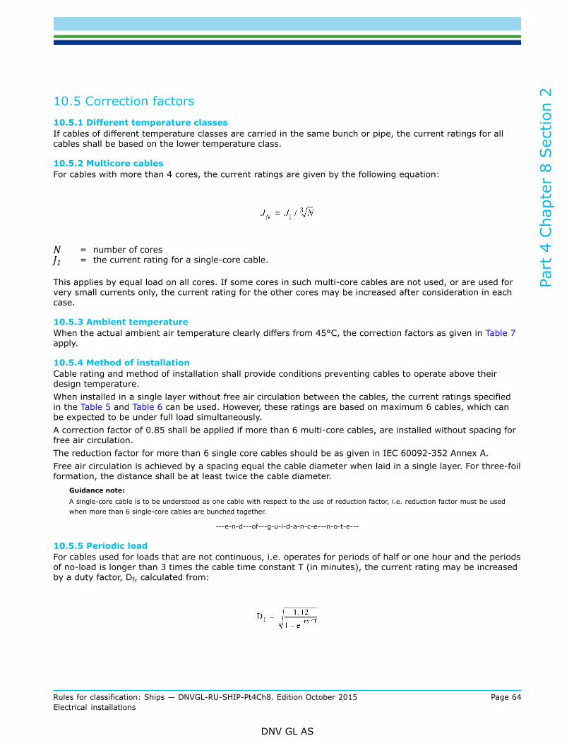
Part
4 C
hapt
er 8
Sec
tion
2
Rules for classification: Ships — DNVGL-RU-SHIP-Pt4Ch8. Edition October 2015 Page 64Electrical installations
DNV GL AS
10.5 Correction factors10.5.1 Different temperature classesIf cables of different temperature classes are carried in the same bunch or pipe, the current ratings for allcables shall be based on the lower temperature class.
10.5.2 Multicore cablesFor cables with more than 4 cores, the current ratings are given by the following equation:
N = number of coresJ1 = the current rating for a single-core cable.
This applies by equal load on all cores. If some cores in such multi-core cables are not used, or are used forvery small currents only, the current rating for the other cores may be increased after consideration in eachcase.
10.5.3 Ambient temperatureWhen the actual ambient air temperature clearly differs from 45°C, the correction factors as given in Table 7apply.
10.5.4 Method of installationCable rating and method of installation shall provide conditions preventing cables to operate above theirdesign temperature.When installed in a single layer without free air circulation between the cables, the current ratings specifiedin the Table 5 and Table 6 can be used. However, these ratings are based on maximum 6 cables, which canbe expected to be under full load simultaneously.A correction factor of 0.85 shall be applied if more than 6 multi-core cables, are installed without spacing forfree air circulation.The reduction factor for more than 6 single core cables should be as given in IEC 60092-352 Annex A.Free air circulation is achieved by a spacing equal the cable diameter when laid in a single layer. For three-foilformation, the distance shall be at least twice the cable diameter.
Guidance note:A single-core cable is to be understood as one cable with respect to the use of reduction factor, i.e. reduction factor must be usedwhen more than 6 single-core cables are bunched together.
---e-n-d---of---g-u-i-d-a-n-c-e---n-o-t-e---
10.5.5 Periodic loadFor cables used for loads that are not continuous, i.e. operates for periods of half or one hour and the periodsof no-load is longer than 3 times the cable time constant T (in minutes), the current rating may be increasedby a duty factor, Df, calculated from:

Part
4 C
hapt
er 8
Sec
tion
2
Rules for classification: Ships — DNVGL-RU-SHIP-Pt4Ch8. Edition October 2015 Page 65Electrical installations
DNV GL AS
ts = the service time of the load currents in minutesT = cable's time constant; 0.245 d 1.35
d = overall diameter of the cable in mm.
10.5.6 Intermittent loadCables used for loads that are not continuous, are repetitive and have periods of no-load of less than 3 timesthe cable time constant T (in minutes), the current rating may be increased by an intermittent factor, If,calculated from:
Ts = the service time of the load currents in minutesTp = the intermittent period in minutes (i.e. the total period before of load and no-load before the cycle
is repeated)
ts, T and d, see [10.5.5].
10.6 Parallel connection of cables10.6.1 General
a) Parallel connection can be used for cables having conductor cross-section 10 mm² or above. All cablesthat are parallel connected shall be of the same length, cross-section and construction. The current-carrying capacity is the sum of all parallel conductors' current-carrying capacities.
b) A two, three or four-core cable, in which all cores are of the same cross-section, can be used as single-core cable by parallel connection of all cores in each end. The current-carrying capacity of such single-core cable is the sum of the cores' current-carrying capacities.
c) With parallel connection of multi-core cables, one core of each cable shall be used for each phase andneutral connection, respectively.
d) With many parallel-connected cables, the current distribution may be uneven. However, no single cableshall, after installation, carry more than its capacity. This shall be demonstrated at full load of theconsumer.
10.7 Additional requirements for AC installations, and special DCinstallations10.7.1 General
a) Generally, multi-core cables shall be used on AC installations.b) On three-phase, four-wire circuits, the cross-section of the neutral conductor shall be the same as for a
phase conductor up to 16 mm2, and at least 50% of that of a phase conductor for larger cross-sections,though not larger than 50 mm2. The braiding in a cable shall not be used as the neutral conductor.
c) The neutral conductor shall normally be a part of the power supply cable. Separate neutral cable may beaccepted for cross section above 16 mm2, if the power cable not is provided with magnetic braiding.
10.7.2 Single-core cables
a) Single-core cables shall not have steel-wire braid or armour when used in AC systems and DC systemswith a high “ripple” content.
b) See Sec.10 [3.2.4] and Sec.10 [3.5.6] for fixing of single core cables.

Part
4 C
hapt
er 8
Sec
tion
2
Rules for classification: Ships — DNVGL-RU-SHIP-Pt4Ch8. Edition October 2015 Page 66Electrical installations
DNV GL AS
10.8 Rating of cables10.8.1 Conductor current ratingThe highest continuous load carried by a cable with temperature class 90 °C shall not exceed the currentrating specified in Table 5 and Table 6, with consideration given to the installation method and correctionfactors given in [10.5]. The Table 5 and Table 6 is based on the assumption that the installation permitsfree airflow around the cables, e.g. supported by ladders, cleats, hangers or perforated trays where theholes occupy more than 30% of the area. For other installation methods, or other temperature classes, IEC60092-352 Annex A is to be used.For current rating of wires used inside switchgear and controlgear, see Sec.4 [2.1.6]
Guidance note:Cables used in circuits with non-sinusoidal currents should be de-rated in order to compensate for the additional heat losses. Maker’srecommendations should be followed.
---e-n-d---of---g-u-i-d-a-n-c-e---n-o-t-e---
Table 5 Rating of cables with temperature class 90°C
Current rating (A)
(Based on ambient temperature 45°C)
Nominal
cross-section (mm2)
Single-core 2-core 3 or 4-core
1
1.5
2.5
18
23
30
15
20
26
13
16
21
4
6
10
40
52
72
34
44
61
28
36
50
16
25
35
96
127
157
82
108
133
67
89
110
50
70
196
242
167
206
137
169
95
120
150
293
339
389
249
288
331
205
237
272
185
240
300
444
522
601
377
444
511
311
365
421
DC AC DC AC DC AC
400
500
600
690
780
890
670
720
780
587
663
757
570
612
663
483
546
623
469
504
546

Part
4 C
hapt
er 8
Sec
tion
2
Rules for classification: Ships — DNVGL-RU-SHIP-Pt4Ch8. Edition October 2015 Page 67Electrical installations
DNV GL AS
Table 6 Rating of cables with temperature class 95 °C
Current rating (A)
(Based on ambient temperature 45°C)Nominal
cross-section (mm2)Single-core 2-core 3 or 4-core
1, 5 26 22 18
2,5 32 27 22
4 43 37 30
6 55 47 39
10 76 65 53
16 102 87 71
25 135 115 95
35 166 141 116
50 208 177 146
70 256 218 179
95 310 264 217
120 359 305 251
150 412 350 288
185 470 400 329
240 553 470 387
300 636 541 445
DC AC DC AC DC AC
400 760 725 646 616 532 508
500 875 810 744 689 612 567
630 1010 900 859 765 707 630
Table 7 Correction factors for ambient temperature
Cable
temperature classAmbient temperature (°C)
°C 35 1) 40 45 50 55 60 65 70 75 80 85
60 2) 1.29 1.15 1.00 0.82 - - - - - - -
70 1.18 1.10 1.00 0.89 0.77 0.63
85 1.12 1.06 1.00 0.94 0.87 0.79 0.71 0.61 0.50 - -
90 1.10 1.05 1.00 0.94 0.88 0.82 0.74 0.67 0.58 0.47 -
95 1.10 1.05 1.00 0.95 0.89 0.84 0.77 0.71 0.63 0.55 0.45

Part
4 C
hapt
er 8
Sec
tion
2
Rules for classification: Ships — DNVGL-RU-SHIP-Pt4Ch8. Edition October 2015 Page 68Electrical installations
DNV GL AS
1) Correction factors for ambient temperature below 40°C will normally only be accepted for:
— cables in refrigerated chambers and holds, for circuits which only are used in refrigerated service— cables on vessel with class notation restricting the service to non-tropical water.
2) 60°C cables shall not be used in engine and boiler rooms.

Part
4 C
hapt
er 8
Sec
tion
3
Rules for classification: Ships — DNVGL-RU-SHIP-Pt4Ch8. Edition October 2015 Page 69Electrical installations
DNV GL AS
SECTION 3 EQUIPMENT IN GENERAL
1 General Requirements
1.1 References1.1.1 General
a) This section contains technical requirements for all electrical equipment in general. Additionalrequirements for special types of equipment can be found in Sec.4 to Sec.9.
b) Requirements for electrical systems as a whole can be found in Sec.2. Requirements for installation ofequipment can be found in Sec.10.
1.1.2 Compliance with standardsThe requirements in this section are based on the IEC standard system in general.
Guidance note:IEC Standards covering the general requirements for electrical components for ships are: IEC 60092-101 “Definitions and generalrequirements”, and parts of IEC 60092-201 “Systems design - General”.
---e-n-d---of---g-u-i-d-a-n-c-e---n-o-t-e---
2 Environmental Requirements
2.1 Inclination2.1.1 GeneralThe requirements in Ch.1 Sec.3 Table 3 applies.
2.2 Vibration and acceleration2.2.1 General
a) Electrical equipment and components shall be constructed to withstand, without malfunctioning, orelectrical connections loosening, at least the following values:
— vibration velocity amplitude 20 mm/s in the frequency range 5 to 50 Hz.
b) For flexibly mounted equipment, special considerations shall be given to the construction of theequipment since larger vibrations may occur.
2.3 Temperature and humidity2.3.1 Ambient temperature
a) Electrical equipment including components inside enclosures in switchboards etc., shall be constructedfor continuous operation at rated load, at least within the ambient air temperature ranges listed in Table1 and cooling water temperatures in [2.3.2].
b) Modifications of the equipment may be required if the actual ambient air temperatures will clearly exceedthe limits in a).
c) If some equipment has a critical maximum ambient temperature by which it suddenly fails, this criticaltemperature should not be less than 10°C above the limits specified in the table.
d) For vessels with class notation restricting the service to non-tropical waters, the upper ambient airtemperature limits according to Table 1 may be reduced by 10°C.

Part
4 C
hapt
er 8
Sec
tion
3
Rules for classification: Ships — DNVGL-RU-SHIP-Pt4Ch8. Edition October 2015 Page 70Electrical installations
DNV GL AS
e) For electronic and instrumentation equipment the requirements in Ch.9 applies.Guidance note:These rules do not appraise ambient conditions for transport or storage of electrical equipment.
---e-n-d---of---g-u-i-d-a-n-c-e---n-o-t-e---
Table 1 Ambient air temperature ranges
Minimum ambient airtemperature range for continuousoperation at rated capacity (°C)Location
From To
1 Engine rooms, boiler rooms, galleys andsimilar spaces, accommodation spaces.1) 0 +45
2 Open deck, dry cargo holds, steering gear compartments,
deckhouses, forecastle spaces and similar spaceswhich are not provided with space heating.
-25 +45
3 a) Refrigerated chambers and holds, general. +45
b) Refrigerated chambers and holds, for equipmentwhich only is used in refrigerated service.
The minimumtemperature specified
for the installation,but not above -20
+35
1) Components and systems are to be designed to operate at ambient air temperature in the machinery spacesbetween 0°C and 55°C.
2.3.2 Cooling water temperatureThe requirements in Ch.1 Sec.3 [2.2.1] apply.Electrical equipment on vessels with class notation restricting the service to non-tropical waters shall beconstructed for continuous operation at a seawater temperature up to +25°C.
2.3.3 HumidityElectrical equipment shall be constructed to withstand, and function safely in relative humidity up to 95%.
3 Equipment Ratings
3.1 Electrical parameters3.1.1 General
a) Equipment shall be rated for continuous duty unless otherwise clearly stated by the purchaser (Ref. [5]).b) All conductors, switchgear and accessories shall be of such size as to be capable of carrying, without
their respective ratings being exceeded, the current which can normally flow through them. They shallbe capable of carrying anticipated overloads and transient currents, for example the starting currents ofmotors, without damage or reaching abnormal temperatures.
3.1.2 Voltage and frequency
a) Equipment connected to the system shall be constructed for the system’s nominal frequency andvoltage, voltage drop in distribution, and the tolerances described in Sec.2 [1.2].
b) Any special system, e.g. electronic circuits, whose function cannot operate satisfactorily within the limitsgiven in Sec.2 [1.2] should not be supplied directly from the system but by alternative means, e.g.through stabilized supply.

Part
4 C
hapt
er 8
Sec
tion
3
Rules for classification: Ships — DNVGL-RU-SHIP-Pt4Ch8. Edition October 2015 Page 71Electrical installations
DNV GL AS
3.1.3 Harmonic distortion
a) All equipment shall be constructed to operate at any load up to the rated load, with a supply voltagecontaining harmonic distortion as given in Sec.2 [1.2.7].
3.1.4 Electromagnetic compatibility (EMC)Equipment producing transient voltage, frequency and current variations shall not cause the malfunction ofother equipment on board, neither by conduction, induction or radiation.
Guidance note:The vessel can be divided in three different EMC zones as defined in IEC 60533. Deck and bridge zone, General power distributionzone and Special power distribution zone. Equipment placed in the different zones shall have the corresponding compatibility level.For Deck and bridge zone the compatibility level is given in IEC 60533 or IEC 60945.For General power distribution zone the compatibility level is given in IEC 60533. It is also assumed that either the compatibilitylevel given in the IEC product standards (covering EMC) or the generic EMC standards IEC 61000-6-2 (immunity) and IEC 61000-6-4(emission) will be sufficient.For Special power distribution zone appropriate measures should be taken so that safe operation is assured.
---e-n-d---of---g-u-i-d-a-n-c-e---n-o-t-e---
3.2 Maximum operating temperatures3.2.1 General
a) The temperature rise of enclosures and their different exterior parts shall not be so high that fire risk,damage to the equipment, adjacent materials or danger to personnel occurs. The temperature rise shallnot exceed 50°C. Exemptions may be considered for equipment that is especially protected againsttouching or splashing of oil.
b) For enclosures installed in contact with flammable materials such as wooden bulkheads, the temperaturerise limit is 40°C.
c) For luminaries, resistors and heating equipment, see Sec.8.d) Maximum temperature for operating handles is:
— handles and grips made of metal: 55°C— handles and grips made of insulating material (porcelain, moulded material, rubber or wood): 65°C.
Guidance note:Higher temperatures may be accepted for parts which normally will not be handled with unprotected hands.
---e-n-d---of---g-u-i-d-a-n-c-e---n-o-t-e---
4 Mechanical and Electrical Properties
4.1 Mechanical strength4.1.1 GeneralEquipment shall have sufficient mechanical strength to withstand the strains it is likely to be exposed to wheninstalled.
4.1.2 Enclosures
a) Enclosures shall be resistant to weather, oil and chemicals and have sufficient mechanical strength whenintended to be installed in an area where risk of mechanical damage exists.
b) Metallic enclosures installed on deck or in compartments where severe corrosion problems can beexpected shall be made of especially corrosion resistant material or dimensioned with a suitablecorrosion allowance.

Part
4 C
hapt
er 8
Sec
tion
3
Rules for classification: Ships — DNVGL-RU-SHIP-Pt4Ch8. Edition October 2015 Page 72Electrical installations
DNV GL AS
c) Light metal alloys as i.e. aluminium shall be avoided as enclosure materials if not documented to beseawater resistant and installed so that local corrosion caused by contact does not occur.
d) Enclosures that are so placed that they are likely to be stepped or climbed on, shall be able to withstandthe weight of a man. This applies for example to most electrical machines in the engine room, winchmotors on deck, etc. A test to this effect, with a force of 1000 N applied by a flat surface 70 × 70 mm,may be carried out as type test or random test.
e) Enclosures shall withstand the ambient air temperatures which are specified in [2], with the equipmentat full load. The temperature rise of enclosures shall not be so high that fire risk, damage to adjacentmaterials or danger to personnel occurs.
f) When enclosures of other materials than metal are used, they should at least withstand immersion inwater at 80°C for 15 minutes, without showing signs of deterioration, and the material shall be flameretardant according to IEC 60092-101. A test to this effect may be carried out as type test or randomtest. This also applies to screens of luminaries, and to windows in other enclosures, if made of othermaterial than glass.
4.1.3 Materials
a) Electrical equipment shall be constructed of durable non-hygroscopic materials which are not subject todeterioration in the atmosphere to which it is likely to be exposed.
b) Electrical equipment shall be constructed of at least flame retardant materials.Guidance note:Even in “dry” locations, up to 96% relative humidity with a salt content of 1 mg salt per 1 m³ of air may occur; in machinery spacesalso mist and droplets of fuel- and lubricating oil may also occur.Tests for flame retardant properties are described in IEC 60092-101. Flammability test in accordance with UL94 5VA, 5VB, V0 andV1 can also be accepted.For minor equipment or non-metallic parts of electrical components a glow wire test in accordance with IEC 60695-2-11 may beaccepted. Parts of insulation material necessary to retain current-carrying parts should conform to a test temperature of 960 ºC.
---e-n-d---of---g-u-i-d-a-n-c-e---n-o-t-e---
4.1.4 Material deterioration due to cargo vapoursWhere the cargo gases or vapours are liable to damage the materials used in the construction of electricalapparatus, careful consideration shall be given to the characteristics of the materials selected for conductors,insulation, metal parts, etc. As far as is practicable, components of copper and aluminium, shall beencapsulated to prevent contact with gases or vapours.
Guidance note:Attention is drawn to the possibility of gases and vapours being transferred from one point to another through cables or cable ductingunless appropriate precautions are taken, for example, adequate end sealing.
---e-n-d---of---g-u-i-d-a-n-c-e---n-o-t-e---
4.2 Cooling and anti-condensation4.2.1 General
a) Where electrical equipment depends on additional cooling, the following shall be complied with:
— an alarm shall be initiated when auxiliary cooling or ventilation motors stop running. Alternatively aflow monitoring alarm shall be initiated
— for essential services the windings in the cooled equipment shall be equipped with temperaturedetectors for indication and alarm of winding temperature
— for important services the windings in the cooled equipment shall be equipped with temperaturedetectors for alarm at high winding temperature.
b) Where the cooling of electrical equipment depends upon general room ventilation only, temperaturedetectors in the equipment are not required.

Part
4 C
hapt
er 8
Sec
tion
3
Rules for classification: Ships — DNVGL-RU-SHIP-Pt4Ch8. Edition October 2015 Page 73Electrical installations
DNV GL AS
4.2.2 Water cooled heat exchangers
a) Where cooling of equipment is arranged through air-water heat exchangers, these shall be arranged toprevent entry of water into the equipment, whether by leakage or condensation. Leakage alarm shall beprovided.
b) Heat exchangers in high voltage equipment shall be of double tube type and shall be fitted with leakagealarm.
c) The construction and certification of air-water heat exchangers shall comply with the requirements forpressure equipment, see Ch.7.
d) For direct water cooling of semi-conductor equipment, see Sec.7.Guidance note:Leakage detection is not required for jacket water cooled rotating machines due to the low probability for water leak into the machine.
---e-n-d---of---g-u-i-d-a-n-c-e---n-o-t-e---
4.2.3 Anti-condensation
a) For equipment where condensation is likely, e.g. due to long idle periods, heating arrangements may berequired.
b) All high voltage converters, transformers and rotating equipment not located in heated and ventilatedspaces, shall be provided with heating elements in order to prevent condensation and accumulation ofmoisture. The heating shall be automatically switched on at stand still.
c) All equipment equipped with air/water heat exchangers shall be provided with heating elements in orderto prevent condensation and accumulation of moisture. The heating shall be automatically switched on atstand still.
4.3 Termination and cable entrances4.3.1 Termination
a) All equipment shall be provided with suitable, fixed terminals in an accessible position with sufficientspace for dismantling and connection of external incoming cables. Twist-on or clamp-on connectionsinside connection boxes for lighting and small power consumers are accepted inside dry accommodation.
b) All connections for current-carrying parts and earthing connections shall be fixed so that they cannotloosen by vibration. This also applies to fixing of mechanical parts when found necessary.
c) Terminals for circuits with different system voltages shall be separated, and clearly marked with thesystem voltage.
d) High voltage terminals, above 1000 V, shall not be located in the same box, or part of enclosure, as lowvoltage terminals.
e) Electrical equipment that needs to be connected to protective earth according to [4.4] shall be providedwith suitable fixed terminal for connecting a protective earth conductor. The terminal shall be identifiedby a symbol or legend for protective earthing (PE).
4.3.2 Cable entrance
a) Cable entrance shall be so arranged that the enclosure keeps its intended IP rating after installation andin operation.
b) Cable entrances shall be fit for the outer diameter of the cable in question.Guidance note:Cable entries from the top on equipment installed on open deck should be avoided unless other alternatives prove impracticable.
---e-n-d---of---g-u-i-d-a-n-c-e---n-o-t-e---

Part
4 C
hapt
er 8
Sec
tion
3
Rules for classification: Ships — DNVGL-RU-SHIP-Pt4Ch8. Edition October 2015 Page 74Electrical installations
DNV GL AS
4.4 Equipment protective earthing4.4.1 General
a) Exposed parts of electrical installations, which are liable, under fault conditions to become live, shall beearthed. Requirements to rating of earth conductors are given in Sec.2 [10.4] additionally to what isrequired in this paragraph.
b) Fixing devices between a high voltage enclosure and steel hull parts shall not be relied upon as the soleearthing connection of the enclosure. An enclosure in this context implies switchgear and controlgearassemblies, transformers, rotating machines and other high voltage equipment.
c) Switchgear and controlgear assemblies shall be fitted with earth connection(s) to ensure earthing ofall metallic non-current carrying parts. In main and emergency switchboards a continuous earth-bar isrequired for this purpose.
d) For the interconnections within an enclosure, for example between the frame, covers, partitions or otherstructural parts of an assembly, the fastening, such as bolting or welding is acceptable, provided that asatisfactory conductive connection is obtained.
e) Compartment doors with components such as switches, instruments, signal lamps, etc. with voltageexceeding 50 V AC or DC shall be connected to the switchboard or enclosure by a separate, flexiblecopper earth conductor. In high voltage equipment, this conductor shall have at least 4 mm² cross-section. A compartment door can be earthed through its metallic hinges when it not carries any electriccomponents. In high voltage equipment, this conductor shall have at least 4 mm² cross-section.
f) Each high voltage switchgear and/or controlgear assembly shall be provided with a main earthingconductor of cross-section at least 30 mm² copper, with at least 2 adequate terminals for connection tothe steel hull. Each unit enclosure and other metallic parts intended to be earthed shall be connected tothis main earthing conductor or bar.
g) Earthed metallic parts of withdrawable components in high voltage equipment shall remain earthed, bymeans of a special earth device, until they have been fully withdrawn. The earthing shall be effectivealso when in test position with auxiliary circuits live.
h) The secondary winding of any current or voltage transformer installed in a high voltage system shallbe earthed by a copper conductor of at least 4 mm2 cross-section. Alternatively, unearthed secondarywinding with overvoltage protection is accepted.Exception:Exception from this requirement is given for machines or equipment:
— supplied at a voltage not exceeding 50 V DC or AC between conductors— supplied at a voltage not exceeding 250 V by safety isolating transformers supplying only one
consuming device. Auto-transformers may not be used for the purpose of achieving this voltage— constructed in accordance with the principle of double insulation.
(Interpretation of SOLAS Ch. II-1/45.1.1)
4.5 Enclosures ingress protection4.5.1 General
a) All equipment shall be constructed to prevent accidental touching of live parts, and shall have enclosureswith a minimum degree of protection dependent upon the installation area, according to the installationrequirements in Sec.10 Table 1, unless a higher degree is required by these rules.
b) For equipment supplied at nominal voltages above 500 V up to and including 1000 V, and which isaccessible to unauthorised personnel, it is in addition required that the degree of protection againsttouching live parts shall be at least IP 4X.
c) High voltage switchgear and controlgear assemblies shall have enclosure type of at least IP 32 wheninstalled in spaces accessible to authorised persons only, and IP 44 in spaces accessible to unauthorizedpersonnel. High voltage switchgear and controlgear without valid type test demonstrating that it will

Part
4 C
hapt
er 8
Sec
tion
3
Rules for classification: Ships — DNVGL-RU-SHIP-Pt4Ch8. Edition October 2015 Page 75Electrical installations
DNV GL AS
withstand the effects of an internal arc may be installed in separate rooms with interlock so that accessis only possible when the equipment is isolated and earthed.
d) High voltage transformers shall have enclosure type of at least IP 23, when located in spaces accessibleonly to authorised personnel, and at least IP 54 in other locations. Alternatively, where a transformeris not contained in an enclosure, a separate transformer room may provide the enclosure of thetransformer. The door of the room shall then be interlocked with the supply switchgear.
e) High voltage rotating electrical machines shall have a degree of protection by enclosure of at least IP 23,unless a higher degree is required by location.
f) Connection boxes of rotating machines shall in all cases have a degree of protection of at least IP 44.Guidance note:Equipment located in machinery spaces may be considered as being accessible to authorised personnel only. The same applies toequipment located in other compartments that normally are kept locked, under the responsibility of the ship's officers.
---e-n-d---of---g-u-i-d-a-n-c-e---n-o-t-e---
4.6 Clearance and creepage distances4.6.1 General
a) The distance between live parts of different potential and between live parts and the cases of otherearthed metal, whether across surfaces or in air, shall be adequate for the working voltage, havingregard to the nature of the insulating material and the conditions of service.
b) Clearance and creepage distances shall be as required in relevant product standards. When productstandards do not give such requirements (e.g. for generators, motors and transformers) the values givenin Sec.4 shall be complied with.
c) Electric insulation, e.g. clearance and creepage distances, shall generally be designed for operation inpollution degree 3 and overvoltage category III as defined in IEC 60664. Lower pollution degree may beaccepted case by case.
Guidance note:Requirements to clearance and creepage distances for high and low voltage switchgear and controlgear is given in Sec.4. For semi-conductor converters in Sec.7.
---e-n-d---of---g-u-i-d-a-n-c-e---n-o-t-e---
5 Marking and Signboards
5.1 General5.1.1 General
a) All equipment shall be externally marked to enable identification in accordance with the documentationof the power distribution system, and be marked with the manufacturer's name. In addition the systemvoltage shall be indicated on switchgear and assemblies.
b) All equipment shall if necessary be marked to ensure correct use.c) See Sec.11 for the requirements for the marking of hazardous area equipment.d) All marking shall be permanently fixed.e) Labels bearing clear and indelible indications shall be so placed that all components and all equipment
can be easily identified.

Part
4 C
hapt
er 8
Sec
tion
3
Rules for classification: Ships — DNVGL-RU-SHIP-Pt4Ch8. Edition October 2015 Page 76Electrical installations
DNV GL AS
5.1.2 Rating plateAll equipment shall be fitted with a rating plate giving information on make, type, current, voltage and powerrating and other necessary data for the application.
Guidance note:More detailed requirements for information noted on rating plates may be found in other applicable sections regarding each equipmenttype contained in this chapter (Sec.4 to Sec.9).
---e-n-d---of---g-u-i-d-a-n-c-e---n-o-t-e---
5.1.3 Labels for switchgear, terminals, cables
a) Internal components in equipment and assemblies such as switchgear, controlgear, fuse gear, socketoutlets, lighting equipment and heating equipment shall be marked with make, type, current, voltageand power rating and other necessary data for the application (i.e. to which standard the equipment isproduced).
b) The switchgear and fuse gear for each circuit shall be marked with circuit designation, cable cross-section and rating of fuses or necessary data for easy recognition of components and circuits accordingto relevant drawings.
c) If the switchboard contains two or more distribution systems with different voltages, the different partsshall be marked with the respective voltages at the partitions.
d) Terminals for circuits with different system voltages shall be clearly separated, and clearly marked withthe voltage.
e) All terminals for connection of external instrumentation and control cables shall be marked.f) External instrumentation and control cables shall be marked for identification inside the cabinet. Each
core in a cable shall be marked in accordance with the applicable IEC technical standard for cableconstruction. See Sec.9 [1.1.3]. The identification marking used shall be reflected in the wiring diagramor schematics.
Guidance note:It is expected that the owner and the builder agree a mutually acceptable method of providing permanent identification marking.
---e-n-d---of---g-u-i-d-a-n-c-e---n-o-t-e---
5.1.4 Signboards and warnings
a) Each switchgear and controlgear fed from more than one individually protected circuit shall be markedwith a warning sign stating that these circuits shall be isolated when the main circuit is isolatedfor maintenance purpose. A warning sign is not required if all live circuits within the enclosure aredisconnected together with the main power circuit.
b) When, for fuses above 500 V, the fuse holders permit the insertion of fuses for lower nominal voltage,special warning labels shall be placed, for example “Caution, 660 V fuses only”.
c) Special “high voltage” warning signboards are required on all high voltage machines, transformers,cables, switchgear and controlgear assemblies.
6 Insulation
6.1 Insulation materials6.1.1 General
a) General purpose insulating materials for supporting conductors shall withstand the temperatures towhich they are likely to be exposed. This is normally ambient temperature plus the heat from theconductor itself during full load.
b) A thermal classification in accordance with IEC 60085 shall be assigned to the insulation system whenused in machines. The normally used classes are shown in Table 2, with the maximum exposuretemperatures (including ambient) shown in the right column.

Part
4 C
hapt
er 8
Sec
tion
3
Rules for classification: Ships — DNVGL-RU-SHIP-Pt4Ch8. Edition October 2015 Page 77Electrical installations
DNV GL AS
c) Insulating materials shall be at least flame retardant. For cables see requirements in Sec.9.d) Insulating materials shall be tracking resistant in accordance with IEC 60112. A tracking index of at least
175 V will be required for low voltage equipment. For high voltage equipment the tracking index shall beminimum 300 V. See Sec.13 regarding tracking index.
Table 2 General insulation classes
Insulation class
(thermal class)
Maximum temperature
°C
A 105
B 130
E 75
F 155
H 180
220 220
7 Inspection and testing
7.1 General7.1.1 General
a) Requirements to inspection and testing of electric equipment are given in the applicable sections in theserules.
b) For equipment that shall be type approved, type tests as listed in Table 3 - Table 5 shall be performed asapplicable.
Table 3 Environmental type tests
Parameters Location Minimum equipment specification Test reference
Inside vesselAmbient temperatures:
+0°C to +45°C, see also [2.3.1] c)IEC 60068-2-2 (Dry heat test)
Temperature
Outside vesselAmbient temperatures:
-25° C to +45°C
IEC 60068-2-2 (Dry heat test)
IEC 60068-2-1 (Cold test)
Humidity All locations Relative humidity up to 95%at all relevant temperatures. IEC 60068-2-30 test Db
Vibration All locationsFrequency range: 5-50 Hz,
Velocity: 20 mm/s (amplitude)
IEC 60068-2-6 test Fc or
IEC 60068-2-64 test Fh
(max 10 times amplification)

Part
4 C
hapt
er 8
Sec
tion
3
Rules for classification: Ships — DNVGL-RU-SHIP-Pt4Ch8. Edition October 2015 Page 78Electrical installations
DNV GL AS
Table 4 Electrical EMC type tests
Parameters Location as definedin IEC 60533 Minimum equipment specification Test reference
All location Insulation Resistance Sec.10 Table 5
All location 1 minute High Voltage Test [4.6]1) Insulation
All location Impulse Voltage Test IEC 61439-1 or IEC 62271-2001)
Conducted Low Frequency
IEC 60533
IEC 61000-4-16
Performance criterion A
Electrical Fast Transient/Burst
IEC 61000-6-2 1) or IEC 60533
IEC 61000-4-4
Performance criterion B
Conducted Radio Frequency
IEC 61000-6-2 1) or IEC 60533
IEC 61000-4-6
Performance criterion A
Radiated Electromagnetic Field
IEC 61000-6-2 1) or IEC 60533
IEC 61000-4-3
Performance criterion A
Electrostatic Discharge
IEC 61000-6-2 1) or IEC 60533
IEC 61000-4-2
Performance criterion B
All locations Immunity
Electrical Slow Transient Surge IEC61000-6-2 1)
IEC61000-4-5
Performance criterion B
Radiated
IEC 61000-6-4 1) or IEC 60533 class ACISPR 16
General powerdistribution zone Emission
Conducted
IEC 61000-6-4 1) or IEC 60533 class ACISPR 16
Radiated
IEC 60533 class B or IEC 60945CISPR 16
EMC
Bridge andOpen Deck zone Emission
Conducted
IEC 60533 class B or IEC 60945CISPR 16
1) If the equipment is covered by an IEC product standard, the product standard shall be used.
Table 5 Type tests for enclosures
Parameters Location Minimum equipment specification Test reference
Ingress protection All location According to Sec.10 Table 1 IEC 60529
Fire integrity All location Flame Retardant (Ref. [4.1.3] b) IEC 60092-101
Surface Temperature All location Max 95°C, see limitation in [3.2]
Corrosion resistance Outside IACS UR E10 (item 12) IEC 60068-2-52, salt mist, test Kb,severity 1.
UV radiation resistance Outside IEC 60068-2-5 IEC 60068-2-5, test C for 80 hours

Part
4 C
hapt
er 8
Sec
tion
4
Rules for classification: Ships — DNVGL-RU-SHIP-Pt4Ch8. Edition October 2015 Page 79Electrical installations
DNV GL AS
SECTION 4 SWITCHGEAR AND CONTROLGEAR ASSEMBLIES
1 Construction
1.1 General1.1.1 Applicable standards
a) Switchgear and controlgear assemblies shall generally comply with IEC 61439-1 and IEC 60092-302 forlow voltage equipment, and IEC 62271-200 for high voltage equipment.
b) Electronic equipment used in switchgear and controlgear shall comply with environmental requirementsgiven in Ch.9 Sec.5.
c) Components and accessories used in switchgear and controlgear assemblies shall in general comply withrelevant IEC product standards.
1.1.2 General
a) All switchboard and controlgear assemblies shall be safe against accidental touching of live conductorsduring normal operation of the switchboard or assemblies. (Interpretation of SOLAS Ch. II-1/45.2)
b) A low voltage switchboard or controlgear assembly shall be designed to withstand the short circuit forcesfor minimum 1 s, created by the short circuit current and magnitude at the particular point of the systemwithout endangering the integrity of the outer switchboard enclosure. For high voltage switchboard andcontrolgear assemblies, see [2.2.1].
c) For switchgear constructed and type tested in accordance with IEC 61439-1 sections can be designedto withstand the short-circuit stress occurring on the load side of the respective short-circuit protectivedevice as stated in IEC 61439-1. However, this reduced short-circuit level shall not be less than 60% ofthe short circuit rating of the main busbars.
1.1.3 Accessibility
a) Instruments, handles, push buttons or other devices that should be accessible for normal operation shallbe located on the front of switchboard and controlgear assemblies.
b) All other parts that might require operation shall be accessible. If placed behind doors, the interior frontshall comply with enclosure type IP 20. When located in spaces accessible to unauthorised personnel,fuses with accessible current-carrying parts may be permitted, if the door is lockable. Operation in thiscontext means for example reset of protective devices and replacement of control circuit fuses inside theassembly.
c) Doors, behind which equipment requiring operation is placed, shall be hinged.d) Hinged doors, which shall be opened for operation of equipment, shall be provided with easily operated
handles or similar. There are also to be arrangements for keeping the doors in open position.e) All sections of switchboards and controlgear assemblies that require maintenance shall be accessible for
maintenance work.Guidance note:If the construction does not allow periodical maintenance, the assembly may be designed for maintenance free operation during a20-year service life.
---e-n-d---of---g-u-i-d-a-n-c-e---n-o-t-e---
1.1.4 MaterialsFramework, panels and doors are normally to be of steel or aluminium alloy, and shall be of rigidconstruction.
Guidance note:Switchgear and assemblies constructed of other materials may be accepted provided requirements in Sec.3 are complied with.
---e-n-d---of---g-u-i-d-a-n-c-e---n-o-t-e---

Part
4 C
hapt
er 8
Sec
tion
4
Rules for classification: Ships — DNVGL-RU-SHIP-Pt4Ch8. Edition October 2015 Page 80Electrical installations
DNV GL AS
1.1.5 Circuit separation
a) There shall be arranged a separate cubicle for each generator, with flame retardant partitions betweenthe different generator cubicles and between these and other cubicles. The partitions shall withstand theeffect of an internal arc, and prohibit this from spreading to other cubicles.
b) If a low-voltage main switchboard is supplied from a high voltage system, the feeder panels of thelow-voltage switchboard shall be partitioned with arc-resistant segregations as required for generatorcubicles in a).
c) Controlgear for essential or important consumers shall be separated from each other, and from othercurrent carrying parts, by flame retardant partitions providing protection of the cubicle in case of anarcing fault occurring in the neighbouring cubicle. Alternatively, an arrangement without flame retardantpartitions may be accepted, provided the busbar is divided with a circuit breaker with short circuitprotection, located in a separate cubicle. The arrangement shall be so that maintenance work can becarried out in each unit without danger when isolated.
d) Controlgear for non-important consumers may be installed in a common cubicle provided this cubiclecould be effectively isolated.
e) Consumer controlgear installed in main switchboards shall be placed in cubicles separated from all otherparts of the switchboard by partitions of flame retardant material.
f) Equipment for different distribution systems shall be placed in separate switchboards (panels), orshall be separated from each other by partitions clearly marked with the actual voltages and systemidentifications.
g) Switchgear and controlgear assemblies supplied by different supply systems shall not be placed in thesame enclosure.
h) For separation due to system redundancy, see Sec.2.i) Equipment with voltage above 1 kV shall not be installed in the same enclosure as low voltage
equipment, unless segregation or other suitable measures are taken to ensure that access to low voltageequipment is obtained without danger.(IACS UR E11.2)
j) Each outgoing circuit from a switchboard shall be provided with multipoleswitchgear for isolatingpurposes in accordance with [2.1.5]. If remote from the consumer, the switchgear shall be lockable inthe “off” position. For isolating purposes, a group of non-important consumers may be fed from onecommon switchgear.
k) On a distribution board the multipole switchgear may be omitted when maximum 63 A fuses are used.Guidance note:Switching off by an auxiliary circuit will be accepted provided that the off–control switch is placed in front of the relevant compartmentand a manual off-switching means is provided when front door is opened.
---e-n-d---of---g-u-i-d-a-n-c-e---n-o-t-e---
1.1.6 HandrailsMain and emergency switchboards and other switchgear and controlgear assemblies requiring operation shallhave handrails with an insulating surface.
Guidance note:For small assemblies with simple operation handrails may be omitted.
---e-n-d---of---g-u-i-d-a-n-c-e---n-o-t-e---
1.1.7 Nameplates and marking
a) Switchgear and controlgear assemblies shall be marked in accordance with general requirements given inSec.3 [5].
b) Protection devices shall be permanently marked with voltage, current and breaking capabilities.c) Protection devices with adjustable settings shall have means that readily identify the actual setting of the
protective device.d) Circuit designation for outgoing circuits and incoming feeders shall be marked for identification.

Part
4 C
hapt
er 8
Sec
tion
4
Rules for classification: Ships — DNVGL-RU-SHIP-Pt4Ch8. Edition October 2015 Page 81Electrical installations
DNV GL AS
e) The appropriate setting of overload protective device for each circuit shall be permanently indicated atthe location of the protective device. (Interpretation of SOLAS Reg. II-1/45.6.2)
Guidance note:A document placed inside that assembly with the data required in d) and e) will be accepted.
---e-n-d---of---g-u-i-d-a-n-c-e---n-o-t-e---
1.1.8 Clearance and creepage distances for low voltage equipment
a) The minimum clearance and creepage distances for bare busbars in low voltage equipment are given inTable 1, and shall be complied with when insulating materials with tracking index 175 V are used.
b) Clearance or creepage distances lower than what is given in Table 1 may be accepted for switchgear ofstandard design as long as the following conditions are met:
— minimum clearance distance shall be 8 mm, minimum creepage distance shall be 16 mm— the assembly has DNV GL Type Approval and has been tested with impulse voltage test in accordance
with IEC 61439-1— maximum operating temperature of busbars shall be documented to be acceptable with respect to
fixing materials and internal temperature by a full current type test— maximum temperature rise at termination points for external cables shall be 60ºC.
Table 1 Low voltage busbar clearances or creepage between phases (including neutral) andbetween phases and earth
Rated insulation voltage,
AC root mean square or DC (V)Minimum clearances (mm) Minimum creepage distances (mm)
Up to 250 V 15 20
From 250 to 690 V 20 25
Above 690 V (Maximum 1000 V 25 35
1.1.9 Clearance and creepage distances for high voltage equipment
a) The minimum clearance distance in high voltage equipment shall be suitable for the rated voltageconsidering the nature of the insulating material and the transient over voltages developed by switchingand fault conditions. This requirement may be fulfilled by subjecting each assembly type to an impulsevoltage type test according to Table 3. Alternatively, maintaining the minimum distances given in Table 2.
b) Minimum creepage distances for main switchboards and generators are given in Table 4, and for otherequipment in Table 5.
c) All insulating materials for fixing and carrying live parts shall have tracking index of at least 300 Vaccording to IEC 60112.
d) Within the busbar section compartment of a switchgear assembly the minimum creepage distance shallbe at least 25 mm/kV for non-standardised parts. Behind current limiting devices the creepage distanceshall be at least 16 mm/kV. (IACS UR E11 2.3.2)
Table 2 Clearances for high voltage equipment between phases (including neutral) and betweenphases and earth
Highest voltage for equipment, (kV) 1) Minimum clearance distance for (mm)
3.6 55
7.2 90
12 120

Part
4 C
hapt
er 8
Sec
tion
4
Rules for classification: Ships — DNVGL-RU-SHIP-Pt4Ch8. Edition October 2015 Page 82Electrical installations
DNV GL AS
17.5 160
1) Intermediate values with corresponding distances are accepted.
Table 3 Alternative impulse voltage type test
Rated voltage
[kV]
Highest voltage for equipment
[kV]
Rated lightning impulsewithstand voltage
[kV]
3.0
3.33.6 40
6.0
6.67.2 60
10.0
11.012.0 75
15.0 17.5 95
Table 4 Minimum creepage distances for high voltage main switchboards and generators
Minimum creepage distance (for tracking index 300) (mm)Nominal voltage of the system, (V) 1)
300 V 375 V 500 V > 600 V
1000 to 1100 26 2) 24 2) 22 2) 20 2)
3000 to 3300 63 59 53 48
6000 to 6600 113 108 99 90
10 000 to 11 000 183 175 162 150
1) Intermediate values with corresponding distances are accepted.2) Minimum 35 mm is required for busbars and other bare conductors in main switchboards.
Table 5 Minimum creepage distances for other high voltage equipment
Minimum creepage distance (for tracking index 300) (mm)Nominal voltage of the
system, (V) 1)300 V 375 V 500 V > 600 V
1000 to 1100 18 17 15 14
3000 to 3300 42 41 38 36
6000 to 6600 83 80 75 70
10 000 to 11 000 146 140 130 120
1) Intermediate values with corresponding distances are accepted.

Part
4 C
hapt
er 8
Sec
tion
4
Rules for classification: Ships — DNVGL-RU-SHIP-Pt4Ch8. Edition October 2015 Page 83Electrical installations
DNV GL AS
2 Power Circuits
2.1 Power components in assemblies2.1.1 Main busbar sectioningSee Sec.2 for requirements regarding main busbar division arrangement.
2.1.2 Busbar materials
a) Busbars and other conductors shall normally be made of copper or copper covered aluminium.b) Copper coated aluminium or pure aluminium busbar shall be adequately protected against corrosion by
either installing in an air conditioned environment, by special coating sealing the aluminium or by thealuminium itself being seawater resistant.
2.1.3 Rating of busbars
a) The shape, configuration and cross-section shall be such that the temperature rise will not exceed 45°Cat rated load.
b) Busbars and other conductors with their supports shall be so mechanically or thermally dimensioned andfixed that they can withstand for 1 s without detrimental effect the forces occurring by the maximumshort circuit current which can occur.
c) The cross-section of busbars for neutral connection on an AC three-phase, four-wire system, and forequaliser connection on a DC system, shall be at least 50% of the cross-section for the correspondingphases (poles).
d) For maximum temperatures of busbars in type tested and partially type tested assemblies therequirement in [1.1.8] applies.
e) The maximum permissible load for copper busbars with ambient temperature 45°C is given in Table 6.Other ratings may be accepted based on type test reports..
f) Rating of aluminium busbar to be documented by type test report.
2.1.4 FusesFuses shall normally comply with one of the following standards:
— IEC 60269 for low voltage fuses— IEC 60282-1 for high voltage fuses.
2.1.5 Circuit breakers, on-load switches, disconnectors, and contactors
a) Switchgear and controlgear shall be rated as required by Sec.2 [7.2.2], and comply with:
— IEC 60947 for low voltage equipment— IEC 60470, IEC 62271-100, IEC 62271-102, IEC 62271-106 for high voltage equipment.— Low voltage circuit breakers for IT systems shall comply with IEC 60947-2 Annex H.
b) All fault switching and protecting components such as circuit breakers and fuses shall have a faultcurrent withstand and interruption capacity of not less than the maximum short circuit current at therelevant point of their installation.
c) All load switches and contactors shall have a rating not less than the maximum load current at theirpoint of installation. Particularly, contactors shall be protected against the possibility of the contactorbreaking current exceeding their load break capacity in fault situations.
d) Fuse switches using the fuse element as making and breaking contacts are not accepted in place ofisolating switches, where such are required. Switch-disconnectors and fuse-combination units shallcomply with IEC 60947-3.

Part
4 C
hapt
er 8
Sec
tion
4
Rules for classification: Ships — DNVGL-RU-SHIP-Pt4Ch8. Edition October 2015 Page 84Electrical installations
DNV GL AS
e) The construction shall be such that accidental making or breaking, caused by the vessel's inclination,movements, vibrations and shocks, cannot occur.
f) Under-voltage and closing coils, including contactor coils, shall allow closing of the switchgear andcontrolgear when the voltage and frequency are 85 to 110% of nominal value. The under-voltageprotection shall release if the voltage is below 70% or absolutely below 35% of nominal voltage.
g) Each circuit-breaker rated more than 16 A shall be of trip-free type, i.e. the breaking action initiated byshort-circuit and overcurrent relays, or by under-voltage coil, when fitted, shall be fulfilled independentlyof the position or operation of manual handle or of other closing devices.
Table 6 Rating of copper busbars
Maximum permissible loading [A] with 50/60 Hz
Painted (matt-black) Bare
Numbers of bars Numbers of barsWith × thickness
(mm)1
|
2
||
3
|||
4
|| ||
1
|
2
||
3
|||
4
|| ||
15 × 3 230 390 470 - 200 350 445 -
20 × 3 290 485 560 - 250 430 535
20 × 5 395 690 900 - 340 620 855 -
20 × 10 615 1145 1635 - 530 1020 1460 -
25 × 3 355 580 650 - 300 510 615 -
25 × 5 475 820 1040 - 405 725 985 -
30 × 3 415 670 735 - 350 590 700 -
30 × 5 555 940 1170 - 470 830 1110 -
30 × 10 835 1485 2070 - 710 1310 1835 -
40 × 5 710 1180 1410 - 595 1035 1350 -
40 × 10 1050 1820 2480 3195 885 1600 2195 2825
50 × 5 860 1410 1645 2490 720 1230 1560 2380
50 × 10 1260 2130 2875 3655 1055 1870 2530 3220
60 × 5 1020 1645 1870 2860 850 1425 1785 2740
60 × 10 1460 2430 3235 4075 1220 2130 2850 3595
80 × 5 1320 2080 2265 3505 1095 1795 2170 3370
80 × 10 1860 2985 3930 4870 1535 2615 3460 4275
100 × 10 2240 3530 4610 5615 1845 3075 4040 4935
120 × 10 2615 4060 5290 6360 2155 3545 4635 5580
160 x 10 3348 5121 6646 7836 2752 4451 5803 6857
200 x 10 4079 6162 7973 9287 3335 5344 6956 8109

Part
4 C
hapt
er 8
Sec
tion
4
Rules for classification: Ships — DNVGL-RU-SHIP-Pt4Ch8. Edition October 2015 Page 85Electrical installations
DNV GL AS
Note: The current rating is based on 45°C ambient air temperature. Sufficient ventilation must be ensured, or the loadingvalues shall be reduced.
2.1.6 Internal wiring
a) Connections to/from busbars to the short circuit protection shall be installed short-circuit proof, asdefined in Sec.13. This requirement also applies to branching off for control power and measuring signalsfrom busbars and generator terminals.
b) Interconnection between busbars shall be short circuit protected according to Sec.2 [7.2.1], if the lengthof the cable/wire/flexible busbar exceeds 3 m.
c) Switchboard wires shall as a minimum be insulated single core wires unless used in a short circuit proofinstallation requiring double insulating wires or conductors.
d) The maximum permissible load for wires inside switchgear and controlgear assemblies is given in Table7.
Guidance note:In distributions boards where the connections mentioned in a) are sufficiently protected by upstream short circuit protection devices,the required short circuit proof installation may be exempted.
---e-n-d---of---g-u-i-d-a-n-c-e---n-o-t-e---
Table 7 Rating of internal wiring
Bunched, exposed or in conduitsNominal cross-section of conductor- total cross-section in the case of
conductors connected in parallel [mm2] Severalpower circuits
togetherCurrent [A]
One power circuit togetherwith its associated measuringand control wires Current [A]
Wires run singly,
at least oneconductor diameterapart Circuits of allkinds Current [A]
1
1.5
2.5
4
6
10
16
25
35
50
70
95
120
9
12
16
20
26
36
48
66
82
104
130
157
186
12
15
20
27
35
48
65
86
107
133
164
198
231
15
19
25
34
42
58
78
102
125
157
194
231
272
Note
The current ratings shown apply to conductors with a maximum permissible operating temperature [T] on the conductorof 70 °C and an ambient temperature of 45 °C. For conductors with a maximum permissible operating temperature [T]deviating from 70 °C, the current rating is to be determined by applying the correction factor [F].
T 60 °C 65 °C 70 °C 75 °C 80 °C 85 °C
F 0.77 0.89 1.00 1.10 1.18 1.26

Part
4 C
hapt
er 8
Sec
tion
4
Rules for classification: Ships — DNVGL-RU-SHIP-Pt4Ch8. Edition October 2015 Page 86Electrical installations
DNV GL AS
2.1.7 Screening of horizontally installed busbarsHorizontally installed busbars and bare conductors or connections shall be protected by screens, if they areplaced such that there could be a risk of anything falling down on them.
2.1.8 Clearance and creepage distancesSee [1.1.8] for clearance and creepage distances in switchgear and assemblies.
2.2 Additional requirements for high voltage assemblies2.2.1 General design and construction
a) High voltage switchgear and controlgear assemblies shall be metal-enclosed in accordance with IEC62271-200, or of a construction giving equivalent safety with respect to personnel safety and systemintegrity. High voltage switchgear and controlgear assemblies supplying more than one consumer shalltherefore at least meet the requirements to Loss of Service Continuity Category LSC 2.
b) The high voltage switchgear and controlgear shall be able to withstand an internal short circuit arcingfailure with the maximum duration and magnitude, which can occur on the particular point of theinstallation without harmful effect to operators. High voltage switchgear and controlgear shall be typetested to demonstrate that it will withstand the effects of an internal arc failure (e.g. with classificationIAC and testing in accordance with Appendix A of IEC 62271-200). When installed in spaces accessible toauthorised persons only, the switchgear and controlgear shall have accessibility type A. When installed inspaces accessible to unauthorized personnel, the switchgear and controlgear shall have accessibility typeB. The arcing time shall be 1 s unless discrimination makes a shorter test possible. Then arcing time aslow as 0.1 s is accepted.
c) There shall be separate compartments with IP rating to at least IP 20 towards other compartments in thecubicle for at least the following components:
— control and auxiliary devices— each main switching device— components connected to one side of the main switching device (the outgoing circuit)— components connected to the other side of the main switching device (the busbars).Normally, partitions between the compartments shall be made of metal. Alternatively, a partition of othermaterials not intended to be earthed is accepted, provided it is verified that the safety is of at least thesame standard.
d) As required by a), b) and c), there shall be separate busbar compartments for each switchboard cubicle.However, a continuous busbar compartment is permissible if the main high-voltage switchgear issubdivided into two independent and autonomous installations with metal partition between and one ofthe following solutions is used:
— a protection system (arc monitor, busbar differential protection) is installed which detects internalfaults and isolates the affected part of the installation within 100 ms
— accidental arcing is reliably prevented by design measures (e.g. solid insulated busbar systems).
e) Means shall be provided for the disconnection and isolation of all circuit breakers and fused circuitbreakers, either by using withdrawable components or by installation of separate disconnectors(isolators).Exception 1For final feeder circuits where energising of the main switching device from the load side is not possible,the cable terminals and accessories (e.g. voltage and current transformers) may be placed in the samecompartment as the main switching device.Exception 2For high voltage switchgear and controlgear assemblies installed in accordance with Sec.3 [4.5.1] c)Internal Arc Classification may not be required.
Guidance note:

Part
4 C
hapt
er 8
Sec
tion
4
Rules for classification: Ships — DNVGL-RU-SHIP-Pt4Ch8. Edition October 2015 Page 87Electrical installations
DNV GL AS
Accessibility A implies access only by instructed personnel, and that safe operation only is in front of the switchboard.Accessibility Type A: restricted to authorized personnel only.Accessibility Type B: unrestricted accessibility, including that of the general public.Loss of Service Continuity Category LSC 2 as defined in IEC 62271-200 implies that it is possible to get safe access to the cableterminations in a feeder cubicle or an incomer cubicle without powering down (and applying protective earthing) the common busbarfor several other consumers.
---e-n-d---of---g-u-i-d-a-n-c-e---n-o-t-e---
2.2.2 Mechanical interlocks
a) The arrangement in high voltage enclosures shall be such that all operation and functional testing issafeguarded against accidental touching of live parts. For withdrawable switchgear units, it shall bepossible to perform functional testing and maintenance in safety, even when the busbar is live.
b) Doors that can be opened for operation or testing of high voltage parts (e.g. for replacement of fuses, orfor functional testing of a circuit breaker) shall be interlocked so that they cannot be opened before thecomponents inside have been isolated and made safe.
c) It shall be possible to operate the mechanical off of the circuit breaker having the doors closed.d) If the conditions for the closing operation are not fulfilled (e.g. release not energized), switching-on, also
when actuating the mechanical on button, shall not cause the contact pieces to come into contacte) Circuit breakers shall be interlocked with the associated earthing switch.f) Earthing switches shall have making capacity.g) Isolating switches shall be interlocked so that they can only be switched under no load. The use of load-
switch-disconnectors is recommended.h) The openings between the contacts of a withdrawable high voltage component and the fixed contacts, to
which it is connected in service, shall be provided with automatic shutters.i) Withdrawable switchgear units shall be fitted with mechanical interlocking devices effective in the
operating and disconnected position. A key interlock is permitted for maintenance purposes.j) Withdrawable switchgear units shall be locked in place in the operating position.
2.2.3 Control wiring
a) The wiring of auxiliary circuits shall, with the exception of short lengths of wire at terminals ofinstrument transformers, tripping coils, auxiliary contacts etc., be either segregated from the main circuitby earthed metallic partitions (e.g. metallic tubes) or separated by partitions (e.g. tubes or sheathedcables) made of flame retardant insulating material.
b) Fuses of auxiliary circuits, terminals and other auxiliary apparatus requiring access while the equipmentis in service, shall be accessible without exposing high voltage parts.
c) An alarm shall be arranged for voltage loss after the last fuses in each auxiliary power system, where avoltage failure is not self-detecting.
d) A possibility for manual operation of each circuit breaker shall be arranged. However, manual closingof the circuit breakers shall not be possible if the arrangement of the auxiliary circuits is such that theprotection devices are put out of action and the circuit breakers are still closed after a power failure tothe auxiliary circuits.
2.2.4 Safety earthing of high voltage circuitsEach circuit shall be fitted with an integral means of earthing and short circuiting for maintenance purposes,or alternatively an adequate number of portable earthing and short circuiting devices, suitable for use on theequipment in question, shall be kept on board.

Part
4 C
hapt
er 8
Sec
tion
4
Rules for classification: Ships — DNVGL-RU-SHIP-Pt4Ch8. Edition October 2015 Page 88Electrical installations
DNV GL AS
2.2.5 Contactors and motor startersIf the safety of the crew and the selective protection of the ships grid is ensured by connected upstreamdevices high voltage motor starters may be dimensioned according to “damage classification Type a” asdescribed in IEC 62271-106.
Guidance note:IEC 62271-106 sub clause 4.107.3 describes “damage classification Type a: as follows: Any kind of damage is allowed (with theexclusion of external damage to the enclosure, if any) so as to make necessary the replacement of the device as a whole or thereplacement of fundamental parts in addition to the main contacts and/or the arc chambers of the starter.
---e-n-d---of---g-u-i-d-a-n-c-e---n-o-t-e---
2.2.6 Monitoring and alarmsGas insulated switchboards and busbar systems shall have monitoring of the internal gas pressure. Eachgas volume shall be monitored. A pressure drop shall be alarmed. Measures according to manufacturer’sinstruction shall be initiated.
3 Control and Protection Circuits
3.1 Control and instrumentation3.1.1 General
a) Requirements for power supply and distribution of control circuits are given in Sec.2 [8.2].b) For short circuit proof installation of control cables, see [2.1.8].
3.1.2 Control of duplicated consumers
a) Control circuits for duplicated essential and important equipment shall be kept separated from eachother, and not located in the same enclosure.
b) Controlgear for duplicated essential or important equipment shall be mutually independent and shall bedivided between two motor control centres or distribution boards having separate supplies from differentsides of the main switchboard and/or the emergency switchboard.
c) Where switchboards are fitted with bus ties or bus links, the duplicated circuits shall be fed from differentsides of the bus tie.
d) Duplicated equipment for essential or important services shall not be dependent on any common circuitssuch as e.g. contactors for emergency stop.
3.1.3 Signal lampsIncandescent signal lamps shall be arranged so that a lamp short circuit cannot jeopardise the controlsystem.
3.1.4 Protection and synchronising devices
a) Protection and synchronising devices used in switchgear and controlgear assemblies shall in generalcomply with relevant IEC product standards.
b) Current transformers used for protective or control devices shall be suitable for the overcurrent rangeexpected.
c) A single-fault in the synchronisation circuit shall not lead to an asynchronous connection.
3.1.5 Panel-instruments in general
a) Instruments, including current transformers, in switchgear and controlgear shall have a nominal accuracyof 2.5% or better.
b) The upper limit of the scale of ampere-meters and kilowatt-meters shall be at least 130% of the ratedfull load of the circuit. For generators arranged for parallel operation, the scale shall be arranged for

Part
4 C
hapt
er 8
Sec
tion
4
Rules for classification: Ships — DNVGL-RU-SHIP-Pt4Ch8. Edition October 2015 Page 89Electrical installations
DNV GL AS
reading of reverse current or power corresponding to at least 15% of the rated full load of the circuit.The upper limit of the scale of each voltmeter shall be at least 120% of the nominal voltage.
c) Ampere-meters, kilowatt-meters and voltmeters shall be provided with means to indicate rated currentor power and rated voltage, respectively. Instruments shall have effective screening (e.g. by metalenclosures) in order to diminish faulty readings caused by induction from adjacent current-carryingparts.
d) Frequency meters shall be able to indicate values with a range of at least 8% below and above thenominal frequency.
3.1.6 Generator instrumentation and control
a) Each generator cubicle shall as far as possible function independently as required in Sec.2 [8.2]. Thewiring of each generator circuit breaker’s control and release circuits (e.g. under-voltage circuit) isgenerally to be kept within its cubicle. Exemption: shunt-operated circuits for closing/opening of thecircuit-breaker may be carried out e.g. to a common control panel.
b) Each AC generator shall be provided with instrumentation as listed in Sec.2 [8.2]Instrumentation for current, voltage and frequency shall be arranged for simultaneous and continuousreading.
c) When generators are arranged for parallel operation, they shall in addition be provided withsynchronising devices as required by Sec.2 [8.2].
d) Simultaneous functional reading of current and active power shall be provided at operating station formanual operation and synchronisation.Alternatives for d.
— Single voltmeters and ampere-meters with switches for the alternative readings may be accepted.
— Two separate frequency meters for several generators may be used, one with a change-over switchfor connection to all generators, the other connected to the busbars. A “double frequency meter” maybe used for this purpose.
3.1.7 Instrumentation for distribution systems including in and outgoing circuits of switchboards
a) Each secondary distribution system shall be equipped with a voltmeter.b) Incoming feeders in low voltage main switchboards fed from a high voltage system shall be equipped
with voltmeters and ampere-meters. It shall be possible to display the currents and voltages of all threephases.
c) Incoming feeders in low voltage main switchboards fed from a high voltage system shall be equippedwith signal lights for indication of the operation modes On, Off, Tripped and Ready.
3.1.8 Instrumentation for shore connectionsThe shore connection circuit shall be equipped with:
— a phase sequence indicator— a voltmeter or signal lamp.
4 Inspection and Testing
4.1 General4.1.1 Factory testing
a) Switchgear and controlgear assemblies shall be tested at the manufacturer’s works as described in[4.1.2] to [4.1.6].
b) The manufacturer shall submit test results together with the final documentation for the equipment. Thedocumentation shall give information on make, type, serial no., and all technical data necessary for theapplication of the switchboard or assembly, as well as the results of the required tests.

Part
4 C
hapt
er 8
Sec
tion
4
Rules for classification: Ships — DNVGL-RU-SHIP-Pt4Ch8. Edition October 2015 Page 90Electrical installations
DNV GL AS
c) The following tests are required:
— function test: all basic functions, including auxiliary functions, shall be tested— insulation resistance test— high voltage test.
4.1.2 Visual inspectionSwitchboards and assemblies are subject to a visual inspection for verification of general workmanship,creepage and clearance distances, IP rating, ventilation and quality of materials and components.
4.1.3 Function testing
a) All circuits shall be verified installed as shown in the as-built documentation.b) It shall be verified that supply transformers for control circuits without secondary side short circuit
protection are sufficiently protected by the primary side protection. Such verification may be done byapplication of a short circuit on the secondary side.
c) Control and protection shall be tested for correct functioning.Guidance note:Factory testing of switchgear or controlgear assemblies at full power is normally not required.
---e-n-d---of---g-u-i-d-a-n-c-e---n-o-t-e---
4.1.4 Power frequency and insulation resistance test for low voltage switchgear and controlgearassemblies
a) Switchgear and controlgear assemblies shall be subject to a power frequency withstand voltage testbetween the circuits and between live parts and the enclosure. The test voltage shall be as given in Table8 and Table 9. The test voltage shall be applied for at least 5 s at any frequency between 45 and 65 Hz.
b) Insulation resistance shall be measured prior to and on completion of the voltage test. Insulationresistance test voltages and acceptance values are given in Sec.5 Table 4. It shall be verified that thevoltage testing does not cause any reduction in switchgear insulation level. The insulation level shall beat least 1 MOhm.
Guidance note:Electronic equipment should be disconnected, short circuited and or isolated during high voltage test and insulation resistancemeasuring.The secondary winding of current transformers shall be short circuited and disconnected from earth during the test. The secondarywinding of voltage transformers shall be disconnected during the test.The high voltage test needs not to be made for auxiliary circuits protected by a short-circuit protective device rated not higher than16 A, or if an electric function test has been made previously at the rated operating voltage.
---e-n-d---of---g-u-i-d-a-n-c-e---n-o-t-e---
Table 8 Power-frequency withstand voltage for main circuits
Rated insulation voltage(line to line a.c. or d.c)
V
Dielectric test voltage
a.c. r.m.s.
V
Dielectric test voltage 2)
d.c.
V
< 60 1000 1415
60 – 300 1500 2120
300 – 690 1890 2670
690 – 800 2000 2830
800 – 1000 2200 3110

Part
4 C
hapt
er 8
Sec
tion
4
Rules for classification: Ships — DNVGL-RU-SHIP-Pt4Ch8. Edition October 2015 Page 91Electrical installations
DNV GL AS
1000 – 1500 1) N/A 3820
1) For d.c. only2) Test voltages based on IEC 61439-1 Table 8.
Table 9 Power-frequency withstand voltage for auxiliary and control circuits
Rated insulation voltage
(line to line)
V
Dielectric test voltage
a.c.
r.m.s.
V
<12 250
12 – 60 500
60 < See Table 7.
4.1.5 Verification of creepage and clearance distancesClearance and creepage distances shall be verified to be at least as given in Table 1 to Table 5.
4.1.6 Power frequency test for high voltage assemblies
a) Each high voltage assembly shall be subjected to a 1 minute power frequency voltage test.b) The tests are to be performed with all switching devices in the closed position, and with all withdrawable
parts in the operating position.c) Replicas reproducing the field configuration of the high voltage connections may replace voltage
transformers or power transformers. Overvoltage protective devices may be disconnected or removed.d) Test voltages are given in Table 10. The test voltage may be applied at higher than the rated frequency
in order to avoid the disconnection of voltage transformers.e) Insulation resistance shall be measured prior to and on completion of the voltage test. Insulation
resistance test voltages and acceptance values are given in Sec.5 Table 4. It shall be verified that thevoltage testing does not cause any reduction in switchgear insulation level.
f) All auxiliary circuits shall be subjected to a 1 minute voltage test between the circuits and the enclosureaccording to [4.1.4]. The high voltage test needs not to be made for auxiliary circuits protected by ashort-circuit protective device rated not higher than 16 A, or if an electric function test has been madepreviously at the rated operating voltage.
Guidance note:The environmental conditions during voltage tests are normally to be as specified in IEC 60060-1, “High-voltage test techniques,Part 1, General definitions and test requirements”, that is temperature 20°C, pressure 1013 mbar and humidity 11 g water per m³(corresponding to about 60% relative humidity). Correction factors for test voltages at other environmental conditions are givenin IEC 60060-1.
---e-n-d---of---g-u-i-d-a-n-c-e---n-o-t-e---

Part
4 C
hapt
er 8
Sec
tion
4
Rules for classification: Ships — DNVGL-RU-SHIP-Pt4Ch8. Edition October 2015 Page 92Electrical installations
DNV GL AS
Table 10 Test voltages for high voltage assemblies
Nominal voltage of the system(kV)
Highest system
voltage (Um)
or
rated equipment voltage
(kV) 1)
1 minute power frequency test voltage, (kV)
(root mean square value)
To earth and between phases2)
3 - 3.3 3.6 10
6 - 6.6 7.2 20
10 - 11 12 28
15 17.5 38
Note 1): The rated voltage for switchgear and controlgear is equal to the maximum system voltage for which theequipment is designed.
Note 2): Intermediate values for test voltages may be accepted, other than these standard test voltages.
4.1.7 Onboard testingSwitchgear or controlgear assemblies shall be subject to complete function tests after installation onboard.See Sec.10 [4].

Part
4 C
hapt
er 8
Sec
tion
5
Rules for classification: Ships — DNVGL-RU-SHIP-Pt4Ch8. Edition October 2015 Page 93Electrical installations
DNV GL AS
SECTION 5 ROTATING MACHINES
1 General
1.1 References1.1.1 GeneralThe design and function of rotating machines shall generally comply with the requirements of IEC60092-301. For basic machine design, the relevant parts of IEC 60034 apply.
1.2 Requirements common to generators and motors1.2.1 Rating
a) Electrical machines, including any excitation system, shall be designed for continuous duty unlessotherwise clearly stated in the rules for specific application.
b) Generally, maximum environmental temperatures for rotating machines shall be as given in Sec.3 Table1.
1.2.2 Insulation
a) All windings for machines shall be treated to resist moisture, sea air, and oil vapours.b) For general requirements for insulation materials and terminations, see Sec.3 [4].c) The winding insulation for converter-fed motors shall be designed for such application.
1.2.3 Temperature rise in windings (insulation)The maximum permissible temperature rise in windings is given in Table 1, with the following provisions:
a) If the temperature of the cooling medium will be permanently lower than the values given in Sec.3[2.3], then the permissible temperature rise may be increased with the difference between the actualtemperature and the temperature given in Sec.3 [2.3]. Maximum acceptable increase is 20°C.
b) If the ambient temperatures clearly exceed the maximum upper limits, then the temperature rises shallbe decreased accordingly.
c) In Table 1 allowance has been made for the temperature in certain parts of the machine being higherthan measured. The temperatures at such “hot spots” are assumed not to exceed the values given inSec.3 Table 2.
d) For vessels with class notation restricting the service to non-tropical waters the design limits fortemperature rises given in Table 1 may be increased by 10°C. Alternatively, the upper ambient airtemperature limits according to Table 1 may be reduced by 10°C.
e) Where water cooled heat exchangers are used in the machine cooling circuit, the temperature rise shallbe measured with respect to the temperature of the cooling water at the inlet to the heat exchanger.Temperature rises given in Table 1 may be increased by 13°C provided the inlet water does not exceed32°C.
f) If inlet water temperature is above 32°C, permissible temperature rise in Table 1 may be increased by13°C and then reduced by the amount by which the maximum cooling water temperature exceeds 32°C.
g) If the inlet cooling water temperature is permanently less than 32°C, the permissible temperature risein Table 1 may be increased by 13°C and may be further increased by an amount not exceeding theamount by which the cooling temperature is less than 32°C.
h) For machines with insulating class 220 the temperature rise will be evaluated in each case.i) The additional temperature rise caused by the harmonics of currents and voltages shall be taken into
consideration in the design of motors and generators by the maker.

Part
4 C
hapt
er 8
Sec
tion
5
Rules for classification: Ships — DNVGL-RU-SHIP-Pt4Ch8. Edition October 2015 Page 94Electrical installations
DNV GL AS
Table 1 Limits of temperature rise of machines for vessels for unrestricted service based onambient temperature of 45°C
Maximum temperature rise in for
air-cooled machines (ºC)
Insulation classPart of machine 1)Method of
measurement oftemperature 2)
A E B F H
a) AC winding of machine having output of5000 kVA or more
ETD
R
60
55
-3)
-
80
75
105
100
125
1201.
b) AC winding of machine having output of less
than 5000 kVA
ETD
R
60
55
-
70
85
75
105
100
125
120
2. Winding of armature with commutatorsR
T
55
45
70
60
75
65
100
80
120
100
3. Field winding of AC and DC machine with excitationother than those in item 4.
R
T
55
45
70
60
75
65
100
80
120
100
a) Field windings of synchronous machines withcylindrical rotors having DC excitation R 85 105 130
b) Stationary field windings of DC machines havingmore than one layer
ETD
R
T
55
45
70
60
85
75
65
105
100
80
130
120
100
c) Low resistance field windings of AC and DCmachines and compensating windings of DCmachines having more than one layer
R, T 55 70 75 95 1204.
d) Single-layer windings of AC and DC machineswith exposed bare surfaces or varnished metalsurfaces and single compensating windings of DCmachines
R, T 60 75 85 105 130
1) Temperature rise of any part of a machine shall in no case reach such a value that there is a risk of injury to anyinsulating or other material in adjacent parts.
2) R indicates temperature measurement by the resistance method, T the thermometer method and ETD theembedded temperature detector method. In general for measuring the temperature of the windings of a machinethe resistance method shall be applied. (See IEC 60034-1). For stator windings of machines having a rated output of5000 kW (or kVA) the ETD method shall be used. Determination by ETD method requires not less than six detectorssuitably distributed throughout the winding. Highest reading shall be used to determine the temperature for thewinding.
3) For high voltage machines having rated output of 5000 kVA or more, or having a core length of 1 m or more, themaximum temperature rise for class E insulation shall be decreased by 5ºC.
1.2.4 Machine short time overloads
a) General purpose rotating machines shall be designed to withstand the following excess torque:
— AC induction motors and DC motors: 60% in excess of the torque that corresponds to the rating, for15 s, without stalling or abrupt change in speed (under gradual increase of torque), the voltage andfrequency being maintained at their rated value

Part
4 C
hapt
er 8
Sec
tion
5
Rules for classification: Ships — DNVGL-RU-SHIP-Pt4Ch8. Edition October 2015 Page 95Electrical installations
DNV GL AS
— AC synchronous motors with salient poles: 50% in excess of the torque that corresponds to therating, for 15 s, without falling out of synchronism, the voltage, frequency and excitation currentbeing maintained at their rated values
— AC synchronous motors with wound (induction) or cylindrical rotors: 35% in excess of the torquethat corresponds to the rating, for 15 s, without losing synchronism, the voltage and frequency beingmaintained at their rated value.
b) Induction motors for specific applications the excess torque may be subject to special agreement. SeeIEC 60034-1 clause 9.3.
c) General purpose rotating machines shall be designed to withstand the following excess current:
— AC generators: 50% in excess of the rated current for not less than 30 s, the voltage and frequencybeing maintained as near to the rated values as possible
— AC motors: 50% in excess of the rated current for not less than 120 s, the voltage and frequencybeing maintained as near to the rated values as possible
— commutator machines: 50% in excess of the rated current for not less than 60 s, operating at highestfull-field speed.
1.2.5 BalanceMachines shall be so constructed that, when running at any working speed, all revolving parts are wellbalanced.
1.2.6 Lubrication
a) Bearing Lubrication of rotating machines shall be effective under all operating conditions includingtowing.
b) Each self-lubricated sleeve bearing shall be fitted with an inspection lid and means for visual indicationof oil level or use of an oil gauge. Similar requirement applies to self-contained oil lubricated rollerbearings.
c) Provision shall be made for preventing the lubricant from gaining access to windings or other insulated orbare current-carrying parts.
d) For electrical propulsion see Sec.12 [1.6.3] e)
1.2.7 Shafts and shaft currents
a) Shafts shall comply with the requirements in Ch.4 both with regard to strength, bearings and balancing.b) Means shall be provided to prevent damaging levels of circulating currents between shaft, bearings and
connected machinery.c) When all bearings on a machine are insulated, the shaft shall be electrically connected to the machine's
earth terminal.
1.2.8 Shaft locking devicePropulsion shafts shall be provided with shaft locking devices as required by Sec.12 [1.6.3] and Ch.4 Sec.2[2.9.3].
1.2.9 Machine overspeed
a) Rotating machines shall be capable of withstanding 1.2 times the rated maximum speed for a period of 2minutes.
b) for rotating machines coupled to the main propulsion system and not arranged in the main shafting, at1.25 times the rated speed
c) for rotating machines arranged in the main shafting and whose construction makes testing impracticable,proof by computation of mechanical strength is required

Part
4 C
hapt
er 8
Sec
tion
5
Rules for classification: Ships — DNVGL-RU-SHIP-Pt4Ch8. Edition October 2015 Page 96Electrical installations
DNV GL AS
1.2.10 NameplateEach machine shall be provided with nameplate of durable material, giving the following information:
— make, type, serial no.— performance standard— IP rating— rated values for: output apparent power, voltage(s), frequency, current(s), power factor, speed— for AC machines: the winding connection— thermal classification of insulation— duty type, if other than S1— maximum permissible cooling medium temperature— technical data necessary for the application of the machine— total mass.
1.3 Instrumentation of machines1.3.1 Temperature detectors embedded in stator winding
a) Low voltage machines having a rated output above 5000 kW (or kVA), all high voltage machines, and allpropulsion motors shall be provided with temperature detectors in their stator windings, for monitoringand alarm.
b) For machines depending on additional cooling, see Sec.3 [4.2.1].Guidance note:For the requirements in regard to temperature detectors, reference is made to IEC 60034-11.
---e-n-d---of---g-u-i-d-a-n-c-e---n-o-t-e---
2 Additional Requirements for Generators
2.1 General2.1.1 GeneralExciter and voltage regulation equipment is considered as part of the generator.
Guidance note:See Ch.3 regarding the prime movers' speed governor characteristics and Ch.9 regarding instrumentation equipment.
---e-n-d---of---g-u-i-d-a-n-c-e---n-o-t-e---
2.1.2 Automatic voltage regulator (AVR)The AVR shall be capable of keeping the voltage within the values specified for stationary and dynamicvariations.
2.1.3 Available neutral pointGenerators with rating exceeding 1500 kVA, and all high voltage generators, shall be prepared for installationof equipment for short circuit protection of the generator windings.
2.1.4 De-excitationGenerators with rating exceeding 1500 kVA, and all high voltage generators, shall be prepared for externalsignal for initiation of de-excitation of the generator. Other suitable means to achieve the same objective maybe evaluated and accepted.

Part
4 C
hapt
er 8
Sec
tion
5
Rules for classification: Ships — DNVGL-RU-SHIP-Pt4Ch8. Edition October 2015 Page 97Electrical installations
DNV GL AS
2.1.5 Voltage waveformFor AC generators, the voltage shall be approximately sinusoidal, with a maximum deviation from thesinusoidal curve of 5% of the peak value.
2.2 Voltage and frequency regulation2.2.1 Voltage build-up
a) The construction shall normally be such that the generator, when started up, takes up the voltagewithout the aid of an external electric power source.
b) External power sources may be used to take up the voltage on main generators provided thatredundancy for this external source is arranged as required for starting arrangement.
2.2.2 Stationary voltage regulation
a) The voltage regulation shall be automatic, suitable for shipboard condition, and such that the voltage iskept within 97.5% to 102.5% of the rated voltage under all steady load conditions. This is between no-load and full-load current and at all power factors which can occur in normal use, but in any case withpower factor from 0.7 to 0.9 lagging, also taking into consideration the effect of the prime mover's speedcharacteristic.
b) There shall be provision at the voltage regulator to adjust the generator no load voltage.c) The limits in a) may be increased to ±3.5% for emergency sets.
2.2.3 Transient voltage regulation
a) Maximum values (current and power factor) of sudden loads to be switched on and off shall be specified.In case of the absence of precise information concerning the maximum values of the sudden loads, 60%of the rated current with a power factor of between 0.4 lagging and zero shall be used for Type Testing.
b) The voltage variations under transient conditions shall comply with the following:
— when the generator is running at no load, at nominal voltage, and the specified sudden load isswitched on, the instantaneous voltage drop at the generator terminals shall not be more than 15%of the generators nominal voltage. The generator voltage shall be restored to within ±3% of the ratedvoltage within 1.5 s.
— when the specified sudden load is switched off, the instantaneous voltage rise shall not be more than20% of the rated voltage. The generator voltage shall be restored to within ±3% of the rated voltagewithin 1.5 s.
c) For non-paralleling emergency generating sets the regulation limits and time in b) might be increased to±4% within 5 s.
d) On installations where two or more generators are normally run in parallel, the maximum load that canbe switched on may be divided between the generators in relation to their rating and expected maximumduty as individual generator.
e) See Ch.2 and Ch.3 for requirements for the governor of a generator prime mover.Guidance note:Special consideration should be given to the overvoltage that may occur when switching off the generators at full load or overload.This overvoltage should not reach a level that may damage power supplies for AVRs, under-voltage coils, instruments etc. connectedon the generator side of the generator circuit breaker.
---e-n-d---of---g-u-i-d-a-n-c-e---n-o-t-e---

Part
4 C
hapt
er 8
Sec
tion
5
Rules for classification: Ships — DNVGL-RU-SHIP-Pt4Ch8. Edition October 2015 Page 98Electrical installations
DNV GL AS
2.3 Generator short circuit capabilities2.3.1 Short circuit withstand and contribution capabilitiesAC synchronous generators, with their excitation systems, shall, under steady short circuit condition becapable of maintaining, without sustaining any damage, its short circuit current, which shall be at least 3times the rated full load current, for a duration of at least 2 s. (IEC 60092-301 modified clause 4.2.3) Lowershort circuit current and short time duration might be acceptable provided that the selectivity and generatorprotection requirements Sec.2 [7.1.4] and Sec.2 [7.3.1]) are fulfilled analogously.
2.4 Parallel operation2.4.1 Load sharing
a) Generators for parallel running shall be such that the sharing of active and reactive power is stable underall load conditions. Oscillations smaller than ±20% of each generator's rated current can be accepted.
b) In the range 20 to 100% of the rated reactive load of each generator, its actual reactive load (meanvalue, if oscillations occur) shall not differ from its proportionate share of the total reactive load by morethan 10% of the rated reactive load of the largest generator in parallel, or not more than 25% of thesmallest generator's rated reactive load, if this is less than the former.
c) Requirement for sharing of active power is given in Ch.3.Guidance note:The sharing of power is mainly determined by the prime movers' governor characteristics, to which further requirements are givenin Ch.3. Power oscillations, however, are determined both by the prime movers' and generators' characteristics.
---e-n-d---of---g-u-i-d-a-n-c-e---n-o-t-e---
2.4.2 Parallel operation on nets with earthed neutralWhen generators are run in parallel on nets with earthed neutral, it shall be ensured that the equalisingcurrent resulting from harmonics does not exceed 20% of the rated current of each generator.
3 Inspection and Testing
3.1 General3.1.1 Factory testing
a) Electrical machines shall be tested at the manufacturer’s works with the tests specified in this part ofthe rules. Type tests shall be carried out on a prototype of a machine or the first of a batch of machines.Routine tests shall be carried out on each machine.
b) The type tests (TT) and routine tests (RT) that the machines shall undergo are listed in Table 2.Alternative test methods and calculations may be used as stated in the guidance notes. Alternative testmethods and calculations may be used when described in suitable procedures. Such procedures shall beapproved.
c) The tests in Table 2 shall be documented. The documentation shall give information on make, type, serialno., insulation class, all technical data necessary for the application of the machine, as well as the resultsof the required tests.
d) The result of type tests, and the serial number of the type tested machine, shall be specified in thedocumentation of test results for routine tests.
e) Routine tests for squirrel cage motors need not to be performed at rated frequency, as long as the samefrequency also was used at the type test. The type testing should then be performed with both ratedfrequency and the alternative frequency.

Part
4 C
hapt
er 8
Sec
tion
5
Rules for classification: Ships — DNVGL-RU-SHIP-Pt4Ch8. Edition October 2015 Page 99Electrical installations
DNV GL AS
Table 2 Testing and inspection of electrical machines
No. Task Required testfor generators
Required test for
motors
1
Examination of technical documentation.
Visual inspection.
Verification of data on name plate.
TT, RT TT, RT
2 Measurement of insulation resistance. TT, RT TT, RT
3 Measurement of winding resistance. TT, RT TT, RT
4 Verification of the voltage regulation system. TT, RT1)
5 Temperature-rise test at full load. TT TT
6 Overload or overcurrent test2) (IEC 60034-1/9.3 and 9.4). TT TT
7 AC Synchronous generator: Verification of steady short circuit condition.3) TT
8 Overspeed test: 20% in excess of the rated r.p.m. for 2 minutes..4) TT, RT TT5), RT3)
9 Dielectric strength test TT, RT TT, RT
10 No-load test TT, RT TT, RT
11 Verification of degree of enclosure protection (IP). TT TT
12 Verification of bearings TT, RT TT, RT
13 For high voltage machines a steep fronted impulse test, or equivalent, of thecoil interturn insulation shall be carried out according to IEC 60034-15.
Tests on each separate fully processed coil after inserting in the slots arepreferred. Due to various technologies involved, alternative proposals to verifywithstand level of interturn insulation may be considered, e.g. type tests withfully produced sample coils.
RT RT
1) Only functional test of voltage regulator system during Routine test (RT), I.E. verification of [2.2.1] and [2.2.2].ForType Testing, verification of [2.2.3] shall be performed.
2) Overload test for generators. Test of momentary excess torque for motors. The overload/overcurrent test for shaftgenerators, which are arranged in the main shafting and - due to their construction -could not be tested in themanufacturer's works, shall be performed at site with 1,1 times the rated current for 10 minutes
3) For shaft generator systems, verification of steady short-circuit current shall be demonstrated together with theassociated converter-unit see also [2.3.1].
4) Shaft generators arranged in the main shafting and whose construction makes testing impracticable, proof bycomputation of mechanical strength is required
5) Not applicable for squirrel cage motors.
Guidance note 1:Overspeed test (8)Dielectric test to be performed on rotors after overspeed test IEC 60034-1-9.7.
---e-n-d---of---g-u-i-d-a-n-c-e---n-o-t-e---
Guidance note 2:Verification of the voltage regulating system (4)It is to be verified that the generator, together with its voltage regulation system, complies with the functional requirements givenin [2.2].

Part
4 C
hapt
er 8
Sec
tion
5
Rules for classification: Ships — DNVGL-RU-SHIP-Pt4Ch8. Edition October 2015 Page 100Electrical installations
DNV GL AS
---e-n-d---of---g-u-i-d-a-n-c-e---n-o-t-e---
Guidance note 3:High voltage tests/Dielectric strength test (9)
a) A 1 minute high voltage test should be applied to a new and completed machine with all its parts in place under conditionsequivalent to normal working conditions. The test should be in accordance with IEC 60034-1-9.2 “Withstand voltage test”,and should be carried out at the maker's works at the conclusion of the temperature-rise test.
b) For voltage levels to be used, see IEC 60034-1 Table 16, normally (for ac windings of machines between 1 kW and 10 000kW) the test voltage is 1000 V + twice the rated voltage with a minimum of 1500 V.
c) After rewinding or other extensive repair of a machine, it should be subjected to a high voltage test with a test voltage of atleast 75% of that specified in IEC 60034-1-9.2.
d) On carrying out high-voltage test, it may be necessary to short circuit semi-conductors in order to avoid damage of suchparts.
---e-n-d---of---g-u-i-d-a-n-c-e---n-o-t-e---
Guidance note 4:Temperature rise measurement and testing (5)
a) The temperature rise of a machine should be measured at the rated output, voltage and frequency, and the temperaturetest should be carried out at the duty for which the machine is rated and marked, in accordance with the testing methodsspecified in IEC Publication No. 60034-1. See also Guidance note 5.
b) For machines with maximum continuous rating (duty type S1), the temperature rise test should be continued until thermalequilibrium has been reached, that is when the temperature rises of the parts of the machine do not vary by more than agradient of 2 K per hour.
c) For acceptable methods of winding temperature measurement and corresponding maximum temperatures, see Table 1. SeeGuidance note 4 e. to i. regarding the variety of temperature measurement methods.
d) The measurement of final winding temperature at end of the test should be performed within the time limits given in Table 3.
e) If the initial resistance reading is obtained within the time interval specified in Table 3, that reading shall be accepted for thetemperature measurement.
If a resistance reading cannot be made in the time interval specified in Table 3, it shall be made as soon as possible butnot after more than twice the time limits given in Table 3. The temperature shall be measured as a function of time aftershutdown, and correct temperature being determined by extrapolation back to the appropriate time interval of Table 3. (SeeIEC 60034-1 8.6.2 for extended guidance on this subject).
Table 3 Resistance measurement time after switch off
Rated output, P
(kW) (kVA)
Time delay after
switching off power (s)
P ≤ 50 30
50 < P ≤ 200 90
200 < P ≤ 5000 120
5000 < P N/A (see note 2 to Table A1)
f) When the resistance method is used, the temperature for copper windings, Θ1 - Θ2, may be obtained from the ratio of theresistances by the formula:
Θ2 = winding temperature at the end of the test

Part
4 C
hapt
er 8
Sec
tion
5
Rules for classification: Ships — DNVGL-RU-SHIP-Pt4Ch8. Edition October 2015 Page 101Electrical installations
DNV GL AS
Θ1 = winding temperature at the moment of the initial resistance measurement.
The temperature rise is the difference between the winding temperature at the end of the test, and the ambient airtemperature at the end of the test. (Alternatively the water inlet temperature at the end of the test, for water/air heatexchangers.)
The resistance of a machine winding should be measured and recorded using an appropriate bridge method or voltage andcurrent method.
g) When the embedded temperature detector (ETD) method is used, there should be at least six detectors suitably distributedthroughout the machine windings. They should be located at the various points at which the highest temperatures are likelyto occur, and in such a manner that they are effectively protected from contact with the coolant. The highest reading of anETD element should be used to determine compliance with requirements for temperature limits.
h) When there are two or more coil-sides per slot, the ETD elements should be placed between the insulated coil sides. Ifthere is only one coil-side per slot, the ETD method is not a recognised method for determination of temperature rise ortemperature limits in order to verify the compliance of the rating.
i) The thermometer method is recognised in the cases in which neither the ETD method nor the resistance method isapplicable. See IEC 60034-1 for guidance. The measured temperature rises should not exceed the following values:
65K
for class A insulation
80K
for class E insulation
90K
for class B insulation
115K
for class F insulation
140K
for class H insulation.
---e-n-d---of---g-u-i-d-a-n-c-e---n-o-t-e---
Guidance note 5:Alternative methods for temperature rise calculationsTemperature tests at full load may be difficult to realise for large machines, due to insufficient test power being available. One of thefollowing simulated tests, or equivalent, will be subject for approval for synchronous generators and induction motors:
— synchronous feedback, or back to back method, according to IEEE Std. 115-1983, 6.2.2
— zero power factor method, according to IEEE Std. 115-1983, 6.2.3
— open-circuit and short circuit loading method, according to IEEE Std. 115-1983, 6.2.4
— “Equivalent loading and super-position techniques - Indirect testing to determine temperature rice”, according to 60034-29.
---e-n-d---of---g-u-i-d-a-n-c-e---n-o-t-e---
Guidance note 6:Insulation resistance test (2)
a) The insulation resistance of a new, clean dry machine, should be measured immediately after the temperature test has beencarried out and after high voltage test has been carried out using a direct current insulation tester between:
— all current carrying parts connected together and earth
— all current carrying parts of different polarity or phase, where both ends of each polarity or phase are individuallyaccessible.
The minimum values of test voltage and insulation are given in Table 4. The temperature at which the resistance is measuredshould be near the operating temperature, or an appropriate method of calculation may be used.
b) On carrying out insulation resistance test, it may be necessary to short circuit semi-conductors in order to avoid damage tosuch parts.

Part
4 C
hapt
er 8
Sec
tion
5
Rules for classification: Ships — DNVGL-RU-SHIP-Pt4Ch8. Edition October 2015 Page 102Electrical installations
DNV GL AS
Table 4 Minimum insulation resistance values
Rated voltage
Un (V)Minimum test voltage (V) Minimum insulation resistance (MΩ)
Un ≤ 250 2 × Un 1
250 < Un ≤ 1000 500 1
1000 < Un ≤ 7200 1000 (Un / 1000) + 1
7200 < Un ≤ 15 000 5000 (Un / 1000) + 1
---e-n-d---of---g-u-i-d-a-n-c-e---n-o-t-e---
Guidance note 7:Overload testing (6)Overload test is to be carried out as a type test for generators as a proof of overload capability of generators and excitation system,for motors as a proof of momentary excess torque as required in IEC Publication 60034-1. The over current test shall be the proof ofcurrent capability of windings, wires, connections etc. of each machine. The overcurrent test can be done at reduced speed (motors)or at short circuit (generators).Overloads as stated in [1.2.4] are difficult to test on large machines. In case overloads cannot be tested, documentation or calculationsbased on manufacturers proven methods and experience will be accepted.
---e-n-d---of---g-u-i-d-a-n-c-e---n-o-t-e---
Guidance note 8:Alternative methods for measuring excitation current at rated voltage, current and power factor (15)Temperature tests at full load may be difficult to realise for large machines, due to insufficient test power being available. One of thefollowing simulated tests, or equivalent, will be subject for approval for synchronous generators and induction motors:
— load excitation, according to IEEE Std. 115-1983, 6.2.2.
---e-n-d---of---g-u-i-d-a-n-c-e---n-o-t-e---
Guidance note 9:Bearing inspectionUpon completion of the tests, machines which have sleeve bearings are to be opened upon request, to establish that the shaft iscorrectly seated in the bearing shells.
---e-n-d---of---g-u-i-d-a-n-c-e---n-o-t-e---
3.1.2 Onboard testingAll machines shall be tested onboard, after installation, so that acceptable starting and running performanceare verified with full capacity of driven equipment, alternatively full generator load. See Sec.10.

Part
4 C
hapt
er 8
Sec
tion
6
Rules for classification: Ships — DNVGL-RU-SHIP-Pt4Ch8. Edition October 2015 Page 103Electrical installations
DNV GL AS
SECTION 6 POWER TRANSFORMERS
1 General
1.1 General1.1.1 ReferenceThe design of transformers shall in general comply with the requirements of IEC 60092-303 and relevantparts of IEC 60076.
1.2 Design requirements for power transformers1.2.1 General
a) Transformers shall be double wound. Starting transformers and transformers feeding single consumers,as long as the secondary consumer has the same insulation level as the primary side, may be ofautotransformer type.
b) Normally, transformers shall be of the dry air-cooled type. Where forced cooling is used, it shall bepossible to operate at reduced power if the forced cooling fails. Power transformers with forced coolingshall be equipped with monitoring and alarm as required by Sec.3 [4.2.1].
c) High voltage distribution transformers and propulsion transformers shall be equipped with temperaturemonitors according to Sec.2 [7.4.1].
d) All windings for air-cooled transformers shall be treated to resist moisture, sea air, and oil vapours.e) For the general requirements for insulation materials and terminations, see Sec.3 [4].f) For requirements for busbar material see Sec.4 [2.1].g) The effects of the harmonics of currents and voltages shall be taken into consideration in the design of
transformers with predominate semi-conductor loads.h) High voltage propulsion transformers shall be equipped with an earthed shield winding
1.2.2 Liquid immersed transformers
a) Liquid immersed transformers, filled with liquid with flashpoint above 60°C, may be accepted in enginerooms or similar spaces if provisions have been made, when installed, for containing or safe draining of atotal liquid leakage.
b) Normally, liquid immersed transformers shall be of the sealed type. However, conservator type may beaccepted if the construction is such that liquid is not spilled, when the transformer is inclined at 22.5°.
c) Liquid immersed conservator type transformers shall have a breathing device capable of stopping(trapping) moisture from entering into the insulating liquid.
d) Arrangement for containment of accidental leakage shall be arranged.e) A liquid gauge indicating the normal liquid level range shall be fitted.f) Liquid immersed transformers shall be provided with monitoring and alarms as required in Table 1(Ref.
IACS UR E11).
Table 1 Monitoring of liquid immersed transformers
Item Alarm Load reduction or trip Comments
Liquid level, low 1) X
Liquid level, low low 1) X Trip
Liquid temperature, high X

Part
4 C
hapt
er 8
Sec
tion
6
Rules for classification: Ships — DNVGL-RU-SHIP-Pt4Ch8. Edition October 2015 Page 104Electrical installations
DNV GL AS
Liquid temperature, high high X Trip
Gas pressure, high X Trip
Interturn short circuit X Trip
1) There shall be two individual liquid level sensors
1.2.3 Temperature riseTemperature rise for transformers, above ambient, according to Sec.3 [2.3], shall not exceed the followingvalues (measured by the resistance method):
a) Dry type transformer windings:
— insulation class A: 55°C— insulation class E: 70°C— insulation class B: 75°C— insulation class F: 95°C— insulation class H: 120°C— insulation class 220: 145°C
b) Liquid immersed transformers:
— temperature rise for windings: 55°C— temperature rise for liquid when the liquid is in contact with air: 45°C— temperature rise for liquid when the liquid not is in contact with air: 50°C.
1.2.4 Parallel operationTransformers for parallel operation shall have compatible coupling groups and voltage regulation, so that theactual current of each transformer will not differ from its proportionate share of the total load by more than10% of its full load current.
1.2.5 Voltage regulationTransformers supplying secondary distribution systems for general use shall normally have a maximum 2.5%voltage drop from no load to full load at resistive load.
1.2.6 Short circuit withstand strengthTransformers shall be constructed to withstand a primary or secondary terminal short circuit with a durationof minimum 1 s, with rated primary voltage and frequency, without damage to internal parts or enclosure.
1.2.7 NameplateEach power transformer shall be provided with nameplate of durable material, giving the followinginformation:
— make, type, serial no.— performance standard— rated values for: output apparent power, voltage(s), frequency, current(s)— duty type, if other than S1— thermal classification of insulation— IP code of enclosure and termination box— vector group of windings— maximum permissible cooling medium temperature— short circuit impedance value— liquid type (if applicable)— total mass.

Part
4 C
hapt
er 8
Sec
tion
6
Rules for classification: Ships — DNVGL-RU-SHIP-Pt4Ch8. Edition October 2015 Page 105Electrical installations
DNV GL AS
2 Inspection and Testing
2.1 General2.1.1 Factory testing
a) Transformers shall be tested at the manufacturer’s works with the tests specified in this part. Tests notedas type tests (TT) shall be carried out on a prototype or the first of a batch of identical transformers.Tests noted as routine tests (RT) shall be carried out on each transformer.
b) The tests shall be documented. The documentation shall give information on make, type, serial no.,insulation class, all technical data necessary for the application of the transformer, as well as the resultsof the required tests.
c) The result of type tests, and the serial number of the type tested transformer, shall be specified in thedocumentation of test results for a routine test.
d) Required inspection and tests for distribution transformers are given in Table 2.
Table 2 Testing and inspection of transformers
No. Task Type of test IEC reference
1 Inspection of enclosure, terminations, instrumentation or protection RT
2 Measuring of insulation resistance RT
3 Measuring of voltage ratio at no load and check of phase displacement RT IEC 60076-11.16
4 Measuring of winding resistance RT IEC 60076-11.15
5 Short circuit impedance and load losses RT IEC 60076-11.17
6 Measuring of no-load loss and current RT IEC 60076-11.18
7 Separate-source AC withstand voltage test RT IEC 60076-11.19
8 Inducted AC withstand voltage test RT IEC 60076-11.20
9 Temperature rise test TT IEC 60076-11.23
10Partial discharge measurement on transformer windings with Um ≥ 3.6kV. Maximum level of partial discharge shall be 10 pC.
(Not applicable to liquid immersed transformers.)RT IEC 60076-11.22
2.1.2 Temperature rise testTemperature test at full load may be difficult to realise on large transformers, due to insufficient test powerbeing available. One of these simulated tests, or equivalent may be accepted:
— back to back method, according to IEC 60076-11 23.2.2— simulated load method, according to IEC 60076-11 23.2.1.
2.1.3 Separate-source AC withstand voltage test/ high voltage test
a) A high voltage test shall be applied to a new and completed transformers.b) The test shall be carried out immediately after the temperature rise test, when such is required.c) The test shall be applied between each winding and the other windings, frame and enclosure all
connected together. The full test voltage shall be maintained for 1 minute. For test levels, see Table 3.d) Single phase transformers for use in a polyphase group shall be tested in accordance with the
requirements for the transformers as connected together in the system.

Part
4 C
hapt
er 8
Sec
tion
6
Rules for classification: Ships — DNVGL-RU-SHIP-Pt4Ch8. Edition October 2015 Page 106Electrical installations
DNV GL AS
e) After rewinding or other extensive repair the transformer shall be subjected to a high voltage test with atest voltage of at least 75% of that specified in c) above.
2.1.4 Temperature rise testThe insulation resistance of a new, clean dry transformer shall be measured immediately after thetemperature raise test, when such is required, and the high voltage test has been carried out. Test voltageand minimum insulation resistance is given in Table 4. The test shall be carried out between:
— all current carrying parts, connected together, and earth— all current carrying parts of different polarity or phase, where both ends of each polarity or phase are
individually accessible.
Table 3 Test voltages
Highest voltage for equipment Um
(kV r.m.s.)
Rated short duration power
frequency withstand voltage
(kV r.m.s)
≤ 1 3
3.6 10
7.2 20
12 28
17.5 38
Table 4 Test voltages and minimum insulation resistance
Rated voltage Un (V) Minimum test voltage (V) Minimum insulation resistance (MΩ)
Un ≤ 250 2 × Un 1
250 < Un ≤ 1000 500 1
1000 < Un ≤ 7200 1000 (Un /1000) + 1
7200 < Un ≤ 15 000 5000 (Un /1000) + 1
2.1.5 Onboard testingAll transformers shall be subject to function tests with intended loading, after installation onboard.

Part
4 C
hapt
er 8
Sec
tion
7
Rules for classification: Ships — DNVGL-RU-SHIP-Pt4Ch8. Edition October 2015 Page 107Electrical installations
DNV GL AS
SECTION 7 SEMI-CONDUCTOR ASSEMBLIES
1 General Requirements
1.1 General1.1.1 References
a) The design and construction of semi-conductor assemblies shall comply with relevant requirements ofSec.3 and Sec.4. For control and monitoring equipment the requirements are given in Ch.9.
b) Voltage and frequency characteristics of supply networks are given in Sec.2 [1.2].c) The design of semi-conductor assemblies shall comply with the requirements of IEC 60146-1-1 with
applicable requirements modified to suit marine installations like e.g. environmental requirements statedin Sec.3.
d) The design of semi-conductor assemblies for power supply shall in addition to a), b) and c) comply withthe requirements of IEC 62040 series.
e) The design of semi-conductor assemblies for motor drives shall in addition to a) b) and c) comply withthe requirements of IEC 61800 series.
Guidance note:Semi-conductor converters for power supply covers systems with converters with and without means for energy storage. UPS, batterychargers, clean power units etc.
---e-n-d---of---g-u-i-d-a-n-c-e---n-o-t-e---
1.1.2 Technical integrationUnless otherwise stated, it is the responsibility of the Builder to ensure technical integration of transformers,assemblies, motors and generators with respect to:
— rating and cooling (with respect to increased losses)— torque/speed characteristics— acceleration/breaking— bearing currents— harmonic filters— operating philosophies— installation instructions.
1.1.3 FunctionalityAn assembly shall be described in a functional description. This description shall at least cover the followingitems:
— intended use and operational modes— control system— integration versus higher level control system— redundancy for cooling— manual operation— protection functions, trips and shut downs— redundancy— alarms— specific functional requirements given in applicable rules, e.g. Sec.12 for electric propulsion.

Part
4 C
hapt
er 8
Sec
tion
7
Rules for classification: Ships — DNVGL-RU-SHIP-Pt4Ch8. Edition October 2015 Page 108Electrical installations
DNV GL AS
1.2 Design and construction requirements1.2.1 Electrical rating and duty
a) The specified capacity shall at least include a 100% continuous load, and a specified overload capacitygiven by a current of maximum duration of time.
b) Converters for motor drives (including soft starters), shall as a minimum withstand two consecutive startattempts immediately followed after stopping, or starting up from cold without being overheated.
c) For battery chargers and UPS, requirements for charger capacity are given in Sec.2 [4.1.2].
1.2.2 Creepage and clearance distancesCreepage and clearance distances shall be in accordance with relevant product standard, The clearance andcreepage distances given in the relevant IEC standards are reproduced in Table 1 to Table 3. The impulsevoltage test voltages are reproduced in Table 6.For semi-conductor converters for power supply the requirements are given in IEC 60950-1. For semi-conductor converters for motor drives the requirements are given in IEC 61800-5-1
Table 1 Minimum clearance distances for low voltage semi-conductor converters 1)
Nominal voltage of the system, (line voltage); (V) 2) Minimum clearance distance, (mm)
120 0.80
220, 230, 240 1.5
380, 400, 415, 440, 480 3.0
600, 630, 660, 690 5.5
1) Extract from IEC 61800-5-1, Table 7, 8 and 9, and IEC 60950-1, Annex G, Table G.2. Applicable for three phasesystems. If single phase supply, the distance shall be increased one step.
2) Interpolation is not permitted.
Table 2 Minimum clearance distances for high voltage semi-conductor converters 1)
Nominal voltage of the system (maximum line voltage); (V) 2) Minimum clearance distance, (mm)
1732 8.0
6235 25
12470 60
20785 90
1) Extract from IEC 61800-5-1, Table 7, 8 and 9, and IEC 60950-1, Annex G, Table G.2.2) Interpolation is permitted.
Table 3 Minimum creepage distances, semi-conductor converters 1)
Working voltage (V) 2) 3)
(rms)Minimum creepage distance 4), (mm)
100 2.2
160 2.5

Part
4 C
hapt
er 8
Sec
tion
7
Rules for classification: Ships — DNVGL-RU-SHIP-Pt4Ch8. Edition October 2015 Page 109Electrical installations
DNV GL AS
200 3.2
250 4.0
320 5.0
400 6.3
500 8.0
630 10.0
800 12.5
1000 16
1250 20
1600 25
2000 32
2500 40
3200 50
4000 63
5000 80
6300 100
8000 125
10 000 160
1) Extract from IEC 61800-5-1, Table 10, and IEC 60950-1, Table 2N.2) The highest voltage to which the insulation under consideration is, or can be, subjected when the equipment is
operating at its rated voltage under conditions of normal use.3) Interpolation is permitted.4) Based on insulating material group IIIa/b. If the material group is not known, group IIIa/b shall be assumed.
1.2.3 Capacitor dischargeCapacitors within a converter shall be discharged to less than 60 Volt in less than 5 s (or a residual charge ofless than 50 μC) after removal of the power. If this requirement is not achievable, warning signboards shallbe fitted.
1.2.4 Access conditions for high voltage convertersHigh voltage sections of converters shall have enclosures as required for high voltage switchgear in Sec.4.Doors shall be automatically locked unless the main circuit breaker is open and the circuit is earthed.
1.2.5 Cooling
a) Where forced cooling is provided, the apparatus is, unless otherwise particularly required, to be soarranged that the converter cannot remain loaded unless effective cooling is provided, or other effectivemeans of protection against over temperature is provided. See also Sec.3 [4.2.1].
b) Piping shall be arranged to prevent harmful effects due to leakage or condensation, and be installedpreferably in the lower part of the assembly.
c) Requirements for cooling of converters used for propulsion are given in Sec.12.

Part
4 C
hapt
er 8
Sec
tion
7
Rules for classification: Ships — DNVGL-RU-SHIP-Pt4Ch8. Edition October 2015 Page 110Electrical installations
DNV GL AS
1.2.6 Output voltage and frequencyThe output voltage and frequency of the power supply units shall comply with the requirements for powersupply systems given in Sec.2 [1].
1.2.7 Short circuit current capabilitiesConverters serving as power supplies shall be able to supply a short circuit current sufficient for selectivetripping of downstream protective devices without suffering internal damage. Such selective tripping may beachieved by the utilisation of an automatic bypass. Current limiting power supplies, or power supplies limitedby internal temperature may be used for single consumers.
1.2.8 By-pass arrangementFor converters serving as AC power supply units used as emergency or transitional source of power, or aspower supply to essential or important consumers, a manual electrically independent bypass arrangementshall be provided unless redundant supply to the consumers is otherwise ensured.
1.2.9 Location of batteriesRequirements for location of batteries are given in Sec.2 [9.4].
1.2.10 Protection and monitoring
a) Alarm shall be given for power supply failure and trip of unitb) For IT distribution systems (insulated neutral point), alarm shall be given for secondary side earth fault
(except in dedicated supply system for single consumers).c) For liquid cooled converters where the cooling liquid is in direct contact with live parts, the conductivity
shall be monitored, and high conductivity shall give alarm.d) When harmonic filters are integrated in a converter, protection and monitoring as required in Sec.2
[7.7.1] is required.e) Additional requirements for monitoring of converters used in electrical propulsion systems are given in
Sec.12.f) For power supply units with batteries included, the following additional alarms shall be provided:
— when the charging of a battery fails, alternatively if the battery is being discharged— when the automatic bypass is in operation for on-line UPS units.— operation of battery protective device.
g) UPS units used as transitional power supply as defined in SOLAS Ch.II-1 Reg. 42, 4 or 43, 4 or as anindependent power supply to services as defined in SOLAS Ch.II-1 Reg. 42, 2.3 or 43, 2.4. shall inaddition have power supply failure (voltage and frequency) to the connected load,
h) Alarms shall be given to a manned control station.
i) Requirements for protection of batteries and distribution circuits are given in Sec.2 [7].
1.2.11 Emergency stop, shutdown
a) In drives used for applications where emergency stop is required, the emergency stop circuit shallcomply with Sec.2 [8.5.1]. I.e. the emergency stop signal shall be directly connected to trip the mainpower supply to the drive unit, either directly or through the control power circuit for the circuit breaker.Alternative arrangements independent of the software based control system may be accepted (e.g. pulseblocking, disconnection of control voltage to pulse amplifiers.)
b) Requirements for limited shutdown functions for steering and propulsion are given inSec.12 and Ch.10.
1.2.12 RestartIt shall be possible to restart the converter in a normal manner after a blackout. Local resetting/restarting ofthe unit shall not be necessary.

Part
4 C
hapt
er 8
Sec
tion
7
Rules for classification: Ships — DNVGL-RU-SHIP-Pt4Ch8. Edition October 2015 Page 111Electrical installations
DNV GL AS
2 Inspection and Testing
2.1 General2.1.1 Factory testing
a) Converters shall be tested at the manufacturer’s works. Type tests (TT) shall be carried out on aprototype of a converter or the first of a batch of identical converters. Routine tests (RT) shall be carriedout on each converter.
b) The tests shall be documented. The documentation shall give information on make, type, serial no., alltechnical data necessary for the application of the converter, as well as the results of the required tests.
c) The result of type tests, and the serial number of the type tested converter, shall be specified in thedocumentation of test results for routine tests.
d) The type tests and routine tests that semi-conductor converters shall undergo are listed in Table 4.
Table 4 Testing and inspection of semi-conductor converters for power supply / UPS
No. Task Required test converterfor power supply/UPS IEC test reference DNV GL Rule
requirement reference
1 Visual inspection1) TT, RT Sec.3/Sec.4/RUSHIP Pt.4 Ch.8 Sec.7
2 Function test (UPS switch test)2) TT, RT 62040-3pt. 6.2.2.x [1.1.3]
3 Input voltage and frequency tolerance test TT 62040-3pt. 6.4.1.x Sec.2 [1.2]
4 Stored energy and restored energy tests TT 62040-3 pt. 6.4.4 Sec.2 [4.1.2]
5 Insulation tests (High voltage test) TT, RT61800-5-1pt. 5.2.3.2
60146-1-1 pt 7.2[2.1.2]
6 Insulation resistance test3) TT, RT 60146-1-1pt 7.2.3.1 Sec.10 [4.3.3]
7 Rated current test/Full load test4) TT 62040-3 pt 6.4.3.x [1.2]
8 Temperature rise test TT 60146-1-1 pt 7.4.2 Sec.3 [2.3]
9Control and monitoring system
(ref also function test)TT, RT 62040-3 pt.
6.2.2.3.x [1.2.10]
10 Short circuit test TT 62040-3 pt6.4.2.10.x [1.2.7]
11 Cooling failure tests TT, RT 61800-5-1pt.5.2.4.5 [1.2.6] and [1.2.10]
12 Capacitor discharge TT [1.2.3]
13 Pressure test of coolant piping/hoses. RT Ch.6 Sec.10 [4]

Part
4 C
hapt
er 8
Sec
tion
7
Rules for classification: Ships — DNVGL-RU-SHIP-Pt4Ch8. Edition October 2015 Page 112Electrical installations
DNV GL AS
1) Verification of separation, labelling, IP-rating, creepage and clearance distances.2) Including check of auxiliary devices, properties of control equipment and protective devices. (IEC 60146-1-1 pt
7.5.1-3) In accordance with functional description and test program. The light load and function test may beperformed with power modules identically to the ones that shall be installed onboard. The correct power modulesmay be tested separately.
3) Insulation resistance test shall be done in accordance with Sec.10 Table 5.4) Full load current and overcurrent test according to rating as required in [1.2.7]
Table 5 Testing and inspection of semi-conductor converters for motor drives
No. TaskRequired test converter
for motor drivesIEC test reference
DNV GL Rule
requirement reference
1 Visual inspection1) TT, RT 61800-5-1pt. 5.2.1
Sec.3/Sec.4/RUSHIP Pt.4 Ch.8 Sec.7
2 Input voltage and frequency tolerance test TT 62040-3 pt. 6.3.2 Sec.2 [1.2]
3 Light load and function test2) TT, RT 60146-1-1 pt7.3.1 and 7.5 [1.1.3]
4 Impulse voltage test3) TT 61800-5-1pt. 5.2.3.1 61800-5-1 pt. 5.2.3.1
5Insulation tests
(High voltage test)TT, RT
61800-5-1pt. 5.2.3.2
60146-1-1 pt 7.2[2.1.2]
6 Insulation resistance test4) TT, RT 60146-1-1pt 7.2.3.1 Sec.10 [4.3.3]
7 Rated current test/Full load test5) TT 60146-1-1 pt 7.3.2 [1.2]
8 Temperature rise test TT61800-5-1pt. 5.2.3.9
60146-1-1 pt 7.4.2Sec.3 [2.3]
9Control and monitoring system
(ref also function test)TT, RT [1.2.10]
10 Cooling failure tests TT, RT 61800-5-1pt.5.2.4.5 [1.2.6] and [1.2.10]
11 Capacitor discharge TT 61800-5-1pt.5.2.3.7 [1.2.3]
12 Pressure test of coolant piping/hoses RT Ch.6 Sec.10 [4]
13 Breakdown of components test 6) TT 61800-5-1pt. 5.2.3.6.4
Sec.2 [1.1.1] a),
Sec.4 [1.1.2]
b)

Part
4 C
hapt
er 8
Sec
tion
7
Rules for classification: Ships — DNVGL-RU-SHIP-Pt4Ch8. Edition October 2015 Page 113Electrical installations
DNV GL AS
1) Verification of separation, labelling, IP-rating, creepage and clearance distances.2) Including check of auxiliary devices, properties of control equipment and protective devices. (IEC 60146-1-1) In
accordance with functional description and test program. The light load and function test may be performed withpower modules identically to the ones that shall be installed onboard. The correct power modules may be testedseparately.
3) To be performed if clearance and /or creepage distances are less than specified in Table 1, Table 2 and Table 34) Insulation resistance test shall be done in accordance with Sec.10 Table 5.5) Full load current and over current test according to rating as required in [1.2.1] a)6) Only applicable for variable speed drives larger than 1 MW.
2.1.2 High-voltage testingHigh-voltage testing shall be carried out with test voltages as given in relevant product standard. Thesevoltages given in IEC 60146-1-1 are reproduced in Table 6.The test voltage shall be applied for 1 minute for “Type Tests”, and minimum 1 s for Routine Tests. If thecircuit contains capacitors the test may be performed with a DC voltage.
Table 6 High voltage test
Test voltages
Power frequency withstand voltage Impulse voltage levelNominal voltage
of the system AC
r.m.s (V)
DC
(V)
Uimp
(kV)
<50 1250 1770 0.8
100 1300 1840 1.5
150 1350 1910 2.5
300 1500 2120 4
600 1800 2550 6
1000 2200 3110 8
>1000 3000 4250 8
3600 10 000 14 150 20
7200 20 000 28 300 40
12 000 28 000 39 600 60
17 500 38 000 53 700 75
Interpolation is permitted
2.1.3 Onboard testingSemi-conductor converters for power supply and semi-conductor converters for motor drives shall be testedaccording to Sec.10 [4] after installation onboard.
Part
4 C
hapt
er 8
Sec
tion
8
Rules for classification: Ships — DNVGL-RU-SHIP-Pt4Ch8. Edition October 2015 Page 114Electrical installations
DNV GL AS
SECTION 8 MISCELLANEOUS EQUIPMENT
1 General
1.1 Socket outlets and plugs1.1.1 General
a) Socket outlets and plugs with a rated current not exceeding 63 A in AC installations and 16 A in DCinstallations, shall be constructed for making and breaking the rated current by insertion and withdrawalof the plug, unless they are provided with an interlock as described in b).
b) Socket outlets with a rated current above 63 A AC or 16 A DC shall be provided with interlocks so thatthe plug can only be inserted and withdrawn when the switch is in the “off” position.
c) Socket outlets for portable appliances, which are not hand-held during operation (e.g. weldingtransformers, refrigerated containers), shall be interlocked with a switch regardless of rating, maximum1 000 V can be accepted. At each such socket outlet, a warning sign shall be fitted, with text: DANGER(maximum voltage) V AC ONLY FOR CONNECTION OF.... (type of equipment)....
d) Higher voltage socket outlets can only be used for special applications.e) All socket outlets shall be provided with an earthing contact, except that this may be omitted in the
following cases:
— socket outlets on systems with voltage below 50 V AC or DC— socket outlets with double insulated transformers for handheld equipment— for distribution systems with insulated neutral; socket outlets in dry accommodation spaces where
floor covering, bulkhead and ceiling linings are of insulating material. The resistance of the insulatingmaterial shall be at least 50 kOhm. Earth potential shall not be brought into the space, for instancethrough earth conductors, piping etc.
f) Precautions shall be taken so that a plug for one voltage cannot be inserted in a socket outlet for adifferent voltage. Alternatively, warning signboards shall be fitted.
1.2 Lighting equipment1.2.1 General
a) The temperature rise of parts of luminaries that are in contact with the support shall generally notexceed 50°C.
b) The temperature rise limit is 40°C for parts installed in contact with flammable materials, such as forexample wood.
c) For temperature rise of terminals, see Sec.3.d) For other parts, temperatures according to recognised national or international standards, which take
due consideration of the ambient temperatures on vessels, will be accepted.e) Luminaires, floodlights and searchlights shall conform to IEC publications 60598 and 60092-306. Other
standards may be recognised.
1.2.2 Starting devicesStarting devices which develop higher voltages than the supply voltage are generally to be placed within theluminaries.
1.2.3 Discharge of capacitorsEach capacitor of 0.5 μF or more shall be provided with an arrangement that reduces the voltage to not morethan 50 V within 1 minute after disconnection from the supply.

Part
4 C
hapt
er 8
Sec
tion
8
Rules for classification: Ships — DNVGL-RU-SHIP-Pt4Ch8. Edition October 2015 Page 115Electrical installations
DNV GL AS
1.3 Heating equipment1.3.1 GeneralEach separate heating element rated more than 16A is considered as a separate consumer, for which aseparate circuit from a switchboard is required.
1.3.2 Temperature rise limit for heaters
a) Control elements such as switches knobs and handles shall not attain temperatures, while in operation,no higher than
— 55 °C for metal parts or— 65 °C for parts made of porcelain, glass, moulded plastics or wood.
A temperature of 5 °C higher is permissible for parts operated by finger tipping only (inching operation).
b) Electrical space heaters shall be so designed that, based on an ambient temperature of 20 °C, thetemperature of the casing or enclosure and of the air flow from the heater does not exceed 95 °C underdefined test conditions.
Guidance note:It is recommended to provide each heater with an interlocked over temperature thermostat with manual reset, accessible only byuse of a tool. National regulations of the flag state might require such an over temperature cut out.
---e-n-d---of---g-u-i-d-a-n-c-e---n-o-t-e---
1.3.3 Space heaters
a) Space heaters are generally to be of the convection type, and suitable for installation on bulkheads.Radiation heaters and other space heater types may be accepted after consideration in each case.
1.3.4 Heating batteries for ventilation systemsHeating batteries in centralised ventilation systems shall be equipped with the following safety / controlfunctions:
— heating elements shall be interlocked with respect to the air flow either directly controlled by the power tothe fan or by measuring the airflow locally at the heating element
— heating elements shall be equipped with over temperature switch that can be reset manually only— heating elements shall be equipped with thermostat controlgear.
1.3.5 Space heaters combined with air-condition cabinetsThe following additional requirements apply for space heaters integrated in air-conditioning cabinets:
— the maximum temperature rises specified in [1.3.2] shall be complied with, even when the air supply iscompletely shut off
— each cabinet shall be provided with an interlocked over temperature thermostat with manual reset,accessible only by use of tool
— combined cabinets for ceiling installation are accepted provided the ceiling is constructed of incombustiblematerials.
1.3.6 Water heaters
a) Water heaters are normally to have insulated heating elements and shall be installed as separate units.b) The requirements for temperature rises specified in [1.3.2] apply.c) Each water heater shall be provided with a thermostat, sensing the water temperature and maintaining
this at the correct level.d) Continuous flow water heaters shall have a safety thermostat.
Guidance note:Electrode heaters and electrically heated steam boilers may be accepted after assessment of the arrangement in each case.

Part
4 C
hapt
er 8
Sec
tion
8
Rules for classification: Ships — DNVGL-RU-SHIP-Pt4Ch8. Edition October 2015 Page 116Electrical installations
DNV GL AS
Heating by electric elements in the ship's water tanks may be accepted after design assessment of the arrangement in each case.For pressure vessels, the requirements in Ch.7 apply.
---e-n-d---of---g-u-i-d-a-n-c-e---n-o-t-e---
1.3.7 Oil heaters
a) Electric oil heaters are normally to be installed as separate units. Heating by electric heating elements inthe ship's oil tanks is generally not allowed, but may be accepted after special design assessment of thearrangement in each case.
b) The requirements for temperature rises specified in [1.3.2] apply. In addition, the surface temperature ofthe heating elements shall be below the boiling point of the oil, under normal working conditions. Furtherlimitation of the heating elements' temperature may be required.
c) Each oil heater shall be provided with a working thermostat, sensing the oil temperature and maintainingthis at correct level under normal working conditions. In addition, each oil heater shall be provided withan interlocked over-temperature thermostat with manual reset, and with the sensing device installed inclose proximity to the heating elements, so arranged that it will trip the elements, should they tend tooverheat, or become dry. Other arrangements, ensuring equivalent protection, may be accepted afterdesign assessment in each case
Guidance note:The heating element temperature for lubricating oil should be so low that deterioration of the properties is avoided. The oilmanufacturer should be consulted regarding the maximum acceptable element temperature.
---e-n-d---of---g-u-i-d-a-n-c-e---n-o-t-e---
1.4 Cooking and other galley equipment1.4.1 General
a) Cooking equipment is generally to have insulated heating elements. Special equipment, such as forexample high frequency ovens or electrode pots, shall be suitable for marine use, and installed inaccordance with the manufacturer's instructions.
b) Electrode pots giving earth connection of the system shall be fed from separate isolating transformers.c) For oil pots, the requirements for oil heaters in [1.3.7] applyd) The temperature rises in [1.3.2] are accepted.
Table 1 Temperature rises for cooking and other galley equipment
Part Temperature °C
Enclosure parts against the bulkhead and decks 50
Other accessible surface parts, except hot plates with adjacent top plates 50
Hot plates with adjacent top plates, and heating elements No limit 1)
1) Construction and temperatures shall be such that damage and hazards are avoided, when the equipment is used asintended.

Part
4 C
hapt
er 8
Sec
tion
9
Rules for classification: Ships — DNVGL-RU-SHIP-Pt4Ch8. Edition October 2015 Page 117Electrical installations
DNV GL AS
SECTION 9 CABLES
1 Application
1.1 General1.1.1 General
a) This section of the rules contains requirements for selection, construction and rating of fixed electricalcables for permanent installation. Requirements for flexible cables designed for repeated movement arealso covered in this section. Other applicable requirements in other sections shall also be complied with.
b) Requirements for cables for special applications are found in other parts of the rules. For cable selectionsee Sec.2 and for cable installation see Sec.10.
1.1.2 Duty
a) Unless otherwise clearly stated, the rating of electrical cables for power supply to equipment shall be forcontinuous full load duty. Maximum environmental temperatures shall be as given in Sec.3 Table 1.
b) Requirements for cable sizing, and the tables for the current rating of different cable sizes, can be foundin Sec.2.
Guidance note:Cables for fixed installation are generally accepted for the minimum environmental temperature given in Sec.3 Table 1 without testingfor behaviour at low temperature in excess of what is required in the referenced product standards of the 60092 series with thecondition that the cables on open deck are properly fixed and mechanically protected.Flexible cables shall be suitable for the temperatures in which they operate.
---e-n-d---of---g-u-i-d-a-n-c-e---n-o-t-e---
1.1.3 Compliance with IECThe design of all electrical cables installed shall comply with the requirements of applicable IEC Publications.
Guidance note:Power cables constructed in accordance with these IEC standards will normally have an insulating outer sheath. Certified cablesconstructed with outer armour or braid will have sufficient insulating material beneath this outer braid. For cables with an outer metalbraid, the outer braid cannot be used as earth conductor (as given in Sec.2 Table 4).Permanently installed cables for power, control and instrumentation shall normally comply with the specifications of InternationalElectrotechnical Commission's (IEC):
1) Publication No. 60092-350 For general construction and test methods of power, control and instrumentation cables forshipboard and offshore applications”
2) Publication No. 60092-353 For power cables with extruded solid insulation for rated voltage 1 kV and 3 kV for lighting andpower cables.
3) Publication No. 60092-354 For rated voltages 6 kV (Um = 7.2 kV) up to 30 kV (Um = 36 kV) for High Voltage cables.
4) Publication No. 60092-376 For control and instrumentation cables 150/250 V (300 V).
---e-n-d---of---g-u-i-d-a-n-c-e---n-o-t-e---
2 General Cable Construction
2.1 General
2.1.1 This item 2 of the rules contains general requirements for construction of marine cables for permanentinstallation. Requirements applicable to specific type of cables are found in the following items 3 to 7, and

Part
4 C
hapt
er 8
Sec
tion
9
Rules for classification: Ships — DNVGL-RU-SHIP-Pt4Ch8. Edition October 2015 Page 118Electrical installations
DNV GL AS
may open for solutions outside the requirements in this item 2. Other constructions and materials may beaccepted when designed for special purposes.
2.2 Fire properties2.2.1 General
a) All switchboard wires, electrical cables and wiring external to equipment shall be at least of a flame-retardant type. (This requirement is intended to cover SOLAS Ch. II-1/45.5.2.)
b) A single cable shall be flame retardant according to IEC 60332-1.
2.3 Conductors2.3.1 Conductors
a) All conductors shall consist of plain or metal-coated annealed copper according to IEC 60092-350 andshall be stranded according to IEC 60228 class 2 or class 5.
b) Class 1 (solid conductors) is accepted for data communication cables (Cat. Cables) where thetermination assembly provides sufficient mechanical integrity.
c) Class 6 is accepted for flexible cables.Guidance note:The use of other conductor metals may be considered in applications where copper cannot be used for chemical reasons. See Pt.5Ch.7 Sec.17. See also Sec.10 [2.4.1].
---e-n-d---of---g-u-i-d-a-n-c-e---n-o-t-e---
2.3.2 Conductor cross section
a) Conductor cross sections shall be based on the rating of the over current and short circuit protectionused. However the minimum cross section shall be:
— 0.5 mm2 for 250 V for cables and switchboard wires for control and instrumentation— 1.0 mm2 for power circuit switchboard wires— 1.0 mm2 for 0.6/1 kV power cables with the following exceptions: 0.75 mm2 may be used for flexible
cables supplying portable consumers in accommodation spaces, and also for internal wiring of lightingfittings, provided that the full load current is a maximum of 6 A and that the circuit's short circuitprotection is rated at a maximum of 10 A
— 10 mm2 for 1.8/3 and 3.6/6 kV cables— 16 mm2 and upwards for 6/10 kV cables. (For higher voltage see Table 6).
b) Minimum cross sections of earth conductors are given in Sec.2. Earth conductors in cables shall beinsulated, except for earth conductors as specified in Sec.2 Table 6.
2.4 Insulating materials2.4.1 General
a) The materials and temperature classes given in Table 1 shall in general be used.b) Electrical and mechanical characteristics shall comply with the specifications of Table 2, 3 and 4,
respectively of IEC 60092-360.c) For cables intended for dynamic applications (flexible cables) other materials may be accepted.
Guidance note:As per IEC 60092-360, PVC insulation and ST1 sheath are withdrawn for maritime use after 01-01-2016.
---e-n-d---of---g-u-i-d-a-n-c-e---n-o-t-e---

Part
4 C
hapt
er 8
Sec
tion
9
Rules for classification: Ships — DNVGL-RU-SHIP-Pt4Ch8. Edition October 2015 Page 119Electrical installations
DNV GL AS
Table 1 Temperature classes for insulating materials
Material Temperature °C
Ethylene propylene rubber (EPR) 90
Hard grade ethylene propylene rubber (HEPR) 90
Cross linked polyethylene (XLPE) 90
Halogen free cross linked polyolefin (HF 90) 90
Silicone rubber, (S 95)1) 95
1) Silicon rubber only to be used together with a varnished glass braid
2.5 Wire braid and armour2.5.1 General
a) Cable braids shall be made of copper, copper alloy, or galvanised steel wire.b) Braid and/or armour shall be separated from the core insulation by an inner non-metallic sheath, by tape
or fibrous braid or roving.c) Irrespective of the metal used, the nominal diameter of the braid wire shall be in accordance with Table
2.
Table 2 Nominal diameter of braided wire
Diameter of core assembly
under braid 1)
(mm)
Minimum diameter of threads
in braid 2)
(mm)
D ≤ 10 0.2
10 < D < 30 0.3
D ≥30 0.4
1) Diameter under braid is fictitious and calculated by the method of IEC 60092-350 Appendix A.2) The “coverage density” of the braid shall be in accordance with IEC 60092-350.
2.6 Protective sheaths2.6.1 General
a) Mechanical and particular characteristics of sheath materials shall comply with the specifications of Table5, 6, 7, and 8 in IEC 60092-360.
b) Material thickness of sheaths shall comply with relevant design standards, see [1.1.3].
2.6.2 Temperature classes for protective sheaths
a) The temperature classes for the sheath material shall be at least 85 °C.b) For cables intended for dynamic applications (flexible cables), other materials may be accepted.c) Sheath materials shall be used in accordance with Table 3

Part
4 C
hapt
er 8
Sec
tion
9
Rules for classification: Ships — DNVGL-RU-SHIP-Pt4Ch8. Edition October 2015 Page 120Electrical installations
DNV GL AS
Table 3 Type of protective sheaths
Material Abbreviateddesignation (IEC)
Based on polyvinylchloride or copolymerof vinylchloride and vinylacetate ST2
Thermoplastic
Halogen free SHF1
Based on polychloroprene rubber SE1
Based on chlorosulphonated polyethyleneor chlorinated polyethylene rubber SHElastomeric or Thermosetting
Halogen free SHF2
3 Low Voltage Power Cables
3.1 Construction of cables rated 0.6/1 kV3.1.1 GeneralThe construction of cables for permanent installations shall normally comply with the requirements of IEC60092-353.
3.1.2 Minimum thickness of insulating wallsThe minimum average thickness of insulating walls shall be in accordance with Table 4.
Table 4 Minimum average thickness of insulating walls for power cables with rated voltage0.6/1.0 kV
Designation of the insulating compound
Nominal cross sectionof conductor (mm2)
EPR
S 95
(mm)
XLPE
HEPR
(mm)
1.5
2.5
4 to 16
25 to 35
1.0
1.0
1.0
1.2
0.7
0.7
0.7
0.9
50
70
95
120
1.4
1.4
1.6
1.6
1.0
1.1
1.1
1.2

Part
4 C
hapt
er 8
Sec
tion
9
Rules for classification: Ships — DNVGL-RU-SHIP-Pt4Ch8. Edition October 2015 Page 121Electrical installations
DNV GL AS
150
185
240
300
400
500
630
1.8
2.0
2.2
2.4
2.6
2.8
2.8
1.4
1.6
1.7
1.8
2.0
2.2
2.4
For smaller cross sections than 1.5 mm2, the insulation thickness shall not be less than specified for 1.5 mm2.
Table 4 is according to IEC 60092-353 for 0.6/1.0 kV cables.
3.2 Switchboard wires3.2.1 General
a) Insulation material shall be one of the following: EPR, HEPR, XLPE, HF90 or S95 .b) The minimum thickness of insulation walls shall be in accordance with Table 4.
4 High Voltage Cables
4.1 Construction of cables rated 1.8/3 kV4.1.1 GeneralThe construction of cables for permanent installations shall normally comply with the requirements of IEC60092-353.
4.1.2 Minimum thickness of insulating wallsThe minimum average thickness of insulating walls shall be in accordance with Table 5
Table 5 Minimum average thickness of insulating walls for power cables with rated voltage1.8/3kV
Designation of the insulating compound
Nominal cross section of
conductor (mm2) EPR
(mm)
XLPE
HEPR
(mm)
10 - 70
95 - 300
400
500
630
2.2
2.4
2.6
2.8
2.8
2.0
2.0
2.0
2.2
2.4
Table 5 is according to IEC 60092-353 for 1.8/3 kV cables.

Part
4 C
hapt
er 8
Sec
tion
9
Rules for classification: Ships — DNVGL-RU-SHIP-Pt4Ch8. Edition October 2015 Page 122Electrical installations
DNV GL AS
4.2 Construction of high voltage cables rated above 1.8/3 kV4.2.1 GeneralThe construction and testing of cables for permanent installations shall normally comply with therequirements of IEC 60092-354.
4.2.2 Minimum thickness of insulating wallsThe minimum average thickness of insulating walls shall be in accordance with Table 6.
Table 6 Minimum average thickness of insulating walls for high voltage cables
Nominal thickness of insulation at rated voltage U0 /U (Um)Nominal cross-sectionalarea of conductor mm2 3.6/6 (7.2) kV
mm
6/10 (12) kV
mm
8.7/15 (17.5) kV
mm
12/20 (24) kV
mm
18/30 (36) kV
mm
10 2.5 - - - -
16 2.5 3.4 - - -
25 2.5 3.4 4.5 - -
35 2.5 3.4 4.5 5.5 -
50 to 185 2.5 3.4 4.5 5.5 8.0
240 2.6 3.4 4.5 5.5 8.0
300 2.8 3.4 4.5 5.5 8.0
400 3.0 3.4 4.5 5.5 8.0
500 to 1000 3.2 3.4 4.5 5.5 8.0
5 Control and Instrumentation Cables
5.1 Construction of control and instrumentation cables rated 150/250 V5.1.1 GeneralThe construction of cables for permanent installations shall normally comply with the requirements of IEC60092-376.
5.1.2 Minimum thickness of insulating wallsThe minimum average thickness of insulating walls shall be used in accordance with Table 7.

Part
4 C
hapt
er 8
Sec
tion
9
Rules for classification: Ships — DNVGL-RU-SHIP-Pt4Ch8. Edition October 2015 Page 123Electrical installations
DNV GL AS
Table 7 Minimum average thickness of insulating walls for control and instrumentation cables
Designation of the insulating compound
XLPE
HEPR
(mm)
EPR
HF 90
S 95
(mm)
Nominal cross sectionof conductor (mm2)
Rated voltage 0.15/0.25 kV
0.50
0.75
1.0
1.5
2.5
0.4
0.5
0.5
0.6
0.6
0.6
0.6
0.6
0.7
0.7
Table 7 is according to IEC 60092-376
6 Data Communication Cables
6.1 General6.1.1 GeneralData communication cables implies Category cables (Cat), field bus cables, and fibre optic cables.
— Category cables shall be constructed in accordance with IEC 61156: Part 1: Generic specification, Part 5:Horizontal floor wiring, and Part 6: Work area wiring.
— Category cables approved in accordance with DNVGL-CP-0403.-Type Approval of Data CommunicationCables - Category Cables are accepted.
— Field bus cables shall be constructed in accordance with IEC 61158-2.— Fibre optic cables shall be constructed in accordance with IEC 60793 and IEC 60794.— Fibre optic cables approved in accordance with DNVGL-CP-0402,-Type Approval of Optical Fibre Cables are
accepted.
6.2 Lightweight electrical cables6.2.1 GeneralLightweight electrical cables shall be constructed and tested in accordance with the technical requirementsgiven throughDNVGL-CP-0400,-Type Approval of Lightweight Electric Cables.
7 Flexible electrical cables
7.1 General
7.1.1 Flexible electrical cables shall be constructed and tested in accordance with the technical requirementsgiven through DNVGL-CP-0417, Type Approval of Flexible Electrical Cables .

Part
4 C
hapt
er 8
Sec
tion
9
Rules for classification: Ships — DNVGL-RU-SHIP-Pt4Ch8. Edition October 2015 Page 124Electrical installations
DNV GL AS
8 Inspection and Testing
8.1 General8.1.1 Factory
a) Cables are normally required to be covered by a Type Approval Certificate. Testing of the individualcables is then not required, except as given below and in Sec.10.
b) For case by case certification of cables, Routine Tests (RT) and Product Sample Tests (PST) shall becarried out. For manufacturers already having other type approved cables, only routine tests arerequired.
c) Cables shall be tested at the manufactures works with the test specified in this part of the rules. Testsnoted as Routine Test (RT) shall be carried out on all cables. Tests noted as Product Sample tests (PST)shall be performed as random test at suitable intervals in order to ensure that products from subsequentproduction confirm to result of type tests, ensuring “equal production”.
d) The following inspection and tests shall be carried out according to IEC 60092-350 (2014 -08) (thebrackets in the listing refers to clauses in the IEC standard):
— checking of rated voltage and cable construction (4.1.3.2) RT— measurement of electrical resistance of conductor (5.2.2) RT— voltage test (5.2.3) RT— insulation resistance test (6.9 ) RT— mechanical/particular characteristics of insulating compounds (8.4 ) PST— mechanical/particular characteristics of sheathing compounds (8.5 ) PST— hot set test for EPR and XLPE insulation and for SE1 and SHF 2 sheath (6.8). PST

Part
4 C
hapt
er 8
Sec
tion
10
Rules for classification: Ships — DNVGL-RU-SHIP-Pt4Ch8. Edition October 2015 Page 125Electrical installations
DNV GL AS
SECTION 10 INSTALLATION
1 General Requirements
1.1 General1.1.1 GeneralReference is made to other sections of this chapter, especially Sec.2 for requirements affecting location,arrangements, and installation of systems in an early project stage, and Sec.3 to Sec.9 for requirementsaffecting the various equipment.
1.1.2 Hazardous areasEquipment in hazardous areas shall be selected, located and installed according to Sec.11.
1.1.3 Safety equipmentAt least the following safety equipment has to be provided for high voltage facilities:
— a voltage detector suitable for the rated voltage of the equipment— a sufficient number of earthing cables according to IEC publication 61230, including insulated fitting tools— an insulating matting (mat for repair / maintenance)— a sufficient number of warning labels "Do not switch"— safety instructions for gas insulated switchboards
2 Equipment
2.1 Equipment location and arrangement2.1.1 General
a) All electrical equipment shall be permanently installed and “electrically safe”. This shall prevent injury topersonnel, when the equipment is handled or touched in the normal manner. (Interpretation of SOLASCh. II-1/45.1.3)
b) All electrical equipment shall be selected and installed so as to avoid electromagnetic (EMC) problemsthus preventing disturbing emissions from equipment, or preventing equipment from becoming disturbedand affecting its intended function(s).
c) Electrical equipment shall be placed in accessible locations so that those parts, which require manualoperation, are easily accessible.
d) Heat dissipating electrical equipment as for example lighting fittings and heating elements, shall belocated and installed so that high temperature equipment parts do not damage associated cables andwiring, or affect surrounding material or equipment, and thus become a fire hazard. (Interpretation ofSOLAS Ch. II-1/45.7)
e) Equipment shall be installed in such a manner that the circulation of air to and from the associatedequipment or enclosures is not obstructed. The temperature of the cooling inlet air shall not exceed theambient temperature for which the equipment is specified.
f) All equipment of smaller type (luminaires, socket outlets etc.) shall be protected against mechanicaldamage either by safe location or by additional protection, if not of a rugged metallic construction.
g) Requirements for installation of switchboards given in Sec.2 [9.2.1] shall also be applied to installation oftransformers.
h) Requirements for rotating machinery arrangement are given in Sec.2 [9.3].i) See Sec.2 [9] for additional requirements for vessel arrangement.

Part
4 C
hapt
er 8
Sec
tion
10
Rules for classification: Ships — DNVGL-RU-SHIP-Pt4Ch8. Edition October 2015 Page 126Electrical installations
DNV GL AS
j) In shower rooms and bath rooms the electrical equipment shall be installed in accordance with IECpublication 60364-7-701.
2.1.2 Ventilation of spaces with electrical equipmentThe ventilation shall be so arranged that water or condensation from the ventilator outlets does not reachany unprotected electrical equipment. See also Sec.2 [9.1.1].
2.1.3 High voltage switchgear and controlgear assembliesAccess to high voltage switchgear rooms and transformer rooms shall only be possible to authorised andinstructed personnel.
Guidance note:Equipment located in machinery spaces may be considered as being accessible only to instructed personnel. The same applies toequipment located in other compartments that are usually kept locked, under the responsibility of the ship's officers.
---e-n-d---of---g-u-i-d-a-n-c-e---n-o-t-e---
2.1.4 Passage in front or behind switchgearThe passageways in front of and behind main and emergency switchboards shall be covered by mats orgratings of oil resistant insulating material, when the deck is made of a conducting material. See also Sec.2[9.2.3] regarding free passage ways for main and emergency switchboards.
Guidance note:Mats complying with IEC 61111 or equivalent standard will be accepted.
---e-n-d---of---g-u-i-d-a-n-c-e---n-o-t-e---
2.1.5 TransformersLiquid immersed transformers shall be installed in an area or space with provisions for complete containmentand drainage of liquid leakage.
2.1.6 Heating and cooking appliances
a) All combustible materials close to heating and cooking appliances shall be protected by incombustible orinsulating materials.
b) Cabling and wiring (feeding) shall be suitable for the possible higher temperature in the terminationroom of such equipment.
c) Additional protection of Infra Red–type of open heating elements shall be installed, if necessary to guardagainst fire and accidental touching.
d) Space heaters are normally to be installed on a free bulkhead space, with about 1 m free air above,and so that for example doors cannot touch the heaters. If not constructed with an inclined top plate, aperforated plate of incombustible material inclined about 30º shall be mounted above each heater. Spaceheaters shall not be built into casings of woodwork or other combustible material.
2.2 Equipment enclosure, ingress protection2.2.1 Enclosure types in relation to locationEquipment enclosures shall comply with Table 1 in relation to the location of where it is installed and for highvoltage equipment, see Sec.3 [4].

Part
4 C
hapt
er 8
Sec
tion
10
Rules for classification: Ships — DNVGL-RU-SHIP-Pt4Ch8. Edition October 2015 Page 127Electrical installations
DNV GL AS
Table 1 Enclosure types in relation to location
LocationSwitchgear
andtransformers
Luminaries Rotatingmachines
Heatingappliances
Socketoutlets
Miscellaneoussuch as
switches andconnection
boxes
Instrumentationand
communicationcomponents
Above thefloor1) IP 22 IP 22 IP 22 IP 22 IP 44 IP 44 IP 44Engine and
boiler rooms15)
Below the floor N IP 44 IP 44 IP 44 N IP 44 IP 55
Dry control rooms andswitchboard rooms IP 20 IP 20 IP 20 IP 20 IP 20 IP 20 IP 20
Navigation bridge, radioroom, control stations IP 22 IP 22 IP 22 IP 22 IP 22 IP 22 IP 22
Closed compartments forfuel oil and lubrication oilseparators
IP 44 IP 44 IP 44 IP 44 N IP 44 IP 44
Fuel oil tanks 2) N N N N N N IP 68
Ballast and other water tanks,bilge wells 2) N N IP 68 IP 68 N N IP 68
Ventilation ducts 13) N N 13) IP 44 13) N N N 13)
Deckhouses, forecastlespaces, steering gearcompartments and similarspaces
IP 22 3) IP 22 IP 22 3) IP 22 IP 44 IP 44 IP44
Ballast pump rooms, columnsbelow main deck andpontoons and similar roomsbelow the load line
IP 44 14) IP 34 44 IP 44 14) IP 44 IP 55 5) IP 55 5) IP 55 5)
Cargo holds, keel ducts, pipetunnels 4) IP 55 N IP 55 IP 55 N IP 55 5) IP 55 5) IP 56 5)
Open deck, keel ducts IP 56 IP 55 IP 56 6) IP 56 IP 56 5) IP 56 5) IP 56
Battery rooms, paint stores,welding gas bottle stores orareas that may be hazardousdue to the cargo or processesonboard 7)
EX 12) EX 12) EX 12) EX 12) EX 12) EX 12) EX 12)
Dry accommodation spaces IP 20 IP 20 IP 20 IP 20 IP 20 IP 20 8) IP 20
Bath rooms and showers N IP 34 11) N IP 44 IP 55N 9) IP 55 11) IP 55 11)
Galleys, laundriesand similar rooms 10) IP 44 IP 34 IP 44 IP 44 IP 44 IP 44 IP 55

Part
4 C
hapt
er 8
Sec
tion
10
Rules for classification: Ships — DNVGL-RU-SHIP-Pt4Ch8. Edition October 2015 Page 128Electrical installations
DNV GL AS
(N: Normally, not accepted for installation in this location.)1) Switchboards and transformers in engine and boiler rooms above the floor may be accepted with IP21 when theswitchgear or transformer has a roof with eaves. If there is a chance of dripping water from piping, condensed water,etc. then a higher IP rating may be necessary. If there is no chance of dripping water, and the room is equipped with airconditioning system, the IP rating for control desks may be as required for dry accommodation spaces.2)For cable pipes and ducts through fuel oil and water tanks, see [3.7].3) Such equipment shall be provided with heating elements for keeping it dry when not in use, regardless of IP rating.The heating elements shall normally be automatically switched on when the equipment is switched off. Continuouslyconnected heating elements may be accepted provided the maximum allowed temperatures are maintained when theequipment is in operation.4) For enclosures in cargo holds, placed so that they are liable to come into contact with the cargo or cargo handling gear,see Sec.3 [4.1]. For truck battery charging arrangements, see Sec.2 [9]. For electrical installations in cargo holds fordangerous goods, see Pt.6 Ch.5 Sec.10. For special category spaces in passenger vessels and ferries see SOLAS Reg.II-2/37. For such cargoes, also national regulations apply. For vessels carrying cars with fuel in their tanks see SOLASReg. II-2/20 3.2.5) IP 44 may be accepted, when placed in a box giving additional protection against ingress of water. Equipment forcontrol and indication of watertight doors and hatches shall have watertightness based on the water pressure that mayoccur at the location of the component, if intrusion of water can affect the control or indication system. For passengervessels, requirements to IP rating for watertight doors are given in SOLAS II-1 Regulation 15.6) Motors on open deck shall have ingress protection IP 56, and either:
— be naturally cooled, i.e. without external cooling fan— be vertically mounted and equipped with an additional steel hat preventing ingress of water or snow into any external
ventilator— or be equipped with a signboard requiring that the motor shall only be used in port, and be provided with additional
covers (e.g. tarpaulins) at sea.7) For arrangement and connection of batteries, see Sec.2. For installations in paint stores, welding gas bottle stores orareas that may be hazardous due to the cargo or processes onboard, the requirements in Sec.11 shall be complied with.Electrical equipment and wiring shall not be installed in hazardous areas unless essential for operational purposes.8) Connection boxes may be accepted installed behind panels in dry accommodation spaces provided that they areaccessible through a hinged panel or similar arrangement.9) Socket outlets shall be so placed that they are not exposed to splash, e.g. from showers. Circuits for socket outletsin bathrooms shall either be fed from a double insulated transformer, or be equipped with residual current device (RCD)with a maximum release current of 30 mA.10) Stoves, ovens and similar equipment may be accepted with IP 22 when additionally protected against water splash byhose or washing of the floor.11) Lower degree of protection may be accepted provided the equipment is not exposed to water splash.12) Type of ingress protection shall be in accordance with the minimum requirements in Sec.11 or minimum requirementsin this table, whichever is the strictest. Minimum explosion group and temperature class shall be one of those specified inSec.11 (some national regulations may limit the choice of type of protection).13) Luminaries and instrumentation components may be accepted after special consideration. It shall be observed that aventilation duct may be a hazardous area, depending upon the area classification at the ends of the duct. Equipment inventilation ducts to open deck shall have IP 55.14) Electric motors, switchgear and starting transformers for thrusters shall be equipped with heating elements forstandstill heating. Provided the space will not be used as pump room for ballast, fuel oil etc., the thrusters motor may beaccepted with IP22 enclosure type.

Part
4 C
hapt
er 8
Sec
tion
10
Rules for classification: Ships — DNVGL-RU-SHIP-Pt4Ch8. Edition October 2015 Page 129Electrical installations
DNV GL AS
15) Electrical and electronic equipment and components located in areas or in the vicinity of areas protected by FixedWater-Based Local Application Fire-Fighting Systems as required by SOLAS Ch. II-2/10 5.6 using fresh water shall be toa degree of protection not less than IP22.
When salt water is used, electrical and electronic equipment and components located in areas, or in the vicinity of areas,protected shall be to a degree of protection not less than IP44, unless the manufacturer of the electrical and electronicequipment or components submits evidence of suitability using a lower degree of protection (e.g. IP23, IP22, etc.)restricted to:
— For the natural air cooled static power equipment (e.g. starter, distribution panel, transformer, lighting etc.) at leastIP23 is required.
— For the natural air cooled electronic equipment mounted or located on the protected system (e.g. sensors, actuators,etc.), at least IP44 is required.
— For the rotating machinery and mechanically air cooled type equipment (e.g., rotating machinery, air cooled SCRpanel, etc.) which needs the forced cooling air from outside the equipment, a lower degree than IP44 may beaccepted if measures are taken, in addition to ingress, to prevent the ingest of water. The terminal boxes shall be ofat least IP44.
Generators with a lower degree of protection as IP44 may be used if they are separated to each other in a way that thewater used for the FWBLAFFS (e.g. water mist, water drops) will harm only the set concerned.
2.3 Batteries2.3.1 Enclosure types in relation to locationBattery installations shall comply with the requirements in Sec.2 [9] (Lead Acid or NiCd technology) or Pt.6Ch.2 Sec.1 (other battery technologies) regarding requirements for their location, compartments etc.
2.3.2 Arrangements and materialsThe following requirements apply to all stationary accumulator batteries:
a) Battery stands, boxes and lockers shall be fixed to the vessel's structure. The batteries shall be fixed orsupported on the shelves. Shelves and fixings shall be constructed to withstand the forces imparted fromthe batteries, during heavy sea.
b) All materials used for the construction, including ventilation ducts and fans, shall be corrosion resistantor shall be protected against corrosion by suitable painting, with consideration given to the type ofelectrolyte actually used.
c) The materials shall be at least flame retardant, except that impregnated wood can be used for thesupport of battery cells, and for battery boxes on deck.
d) Except when corrosion resistant materials are used, the shelves in battery rooms and lockers and thebottom of battery boxes shall be covered with a lining of corrosion resistant material, having a minimumthickness of 1.5 mm and being carried up not less than 75 mm on all sides (e.g. lead sheath for lead andacid batteries, steel for alkaline batteries). If the shelves in battery rooms and lockers are of corrosionresistant materials and the floor is not, either the shelves or the floor shall be covered with such lining.
2.3.3 Marking and signboardsSee [2.5.2] for the requirements for marking and signboards, with respect to battery installations.
2.4 Protective earthing and bonding of equipment2.4.1 General
a) Earth conductors shall normally be of copper. However, other suitable materials may be accepted if, forexample the atmosphere is corrosive to copper.
b) The earth conductor's cross section shall be equivalent to that of copper with regard to conductivity.Applicable arrangements and cross sections are given in Sec.2 Table 6.

Part
4 C
hapt
er 8
Sec
tion
10
Rules for classification: Ships — DNVGL-RU-SHIP-Pt4Ch8. Edition October 2015 Page 130Electrical installations
DNV GL AS
c) The connection to the hull of earth conductors or equipment enclosure parts, which shall be earthed,shall be made by corrosion resistant screws or clamps, with cross section corresponding to the requiredcross section of earth given in Sec.2 [10.4.1].
d) Earthing screws and clamps shall not be used for other purposes. Suitable star washers and conductorterminals shall be used, so that a reliable contact is ensured.
e) Metal enclosures or other exposed conductive parts being a part of electrical equipment shall be earthedby fixing the metal enclosure or exposed parts in firm (conductive) contact to the hull (main earthpotential) or by a separate earth conductor.
f) Portable equipment shall always be earthed by an earth conductor contained in the flexible supply cable.g) All parts supporting electrical equipment and cable support systems, that is ladders, pipes and ducts
for electrical cables, are considered to be in firm electrical contact with the hull as long as elements arewelded or mechanically attached (metal to metal without paint or coating) with a star washer, therebyensuring a firm conductive contact. If firm electrical contact is not achieved, the parts shall be bonded bya separate copper conductor between supporting parts and the hull.
h) Additional precautions shall be applied regarding earthing of portable electrical equipment for use inconfined or exceptionally damp spaces where particular risks due to exposure and conductivity mayexist.
i) High voltage metal enclosures and the steel hull shall be connected by a separate earth conductor. Theenclosures fixing device shall not be the sole earthing connection of the enclosure.
j) If a separate earthing conductor is chosen for equipment, then the connection of the separate earthconductor to the hull, (safe earth potential) shall be made in an accessible position. The conductor shallbe terminated by a pressure type cable lug onto a corrosion protected bolt, which shall be securedagainst loosening. Other suitable terminating systems for direct receipt of the conductor may beconsidered.
Guidance note:Additional precautions in h) might be: The equipment having extra safe low voltage, or for ordinary 230 V equipment, by using asafety transformer system or by having an earth fault switch of maximum 30 mA in front of the circuit.
---e-n-d---of---g-u-i-d-a-n-c-e---n-o-t-e---
2.4.2 Exceptions to the earthing or bonding requirements
a) If one of the following bullet points is fulfilled, the requirements in [2.4.1] may be omitted:
— equipment supplied at a voltage not exceeding 50 V DC or AC between conductors. Auto-transformersshall not be used for the purpose of achieving this voltage
— equipment supplied at a voltage not exceeding 250 V by safety isolating transformer and thetransformer is supplying only one consumer device
— equipment constructed in accordance with the principle of double insulation.
b) Parts fixed to non-conductive materials, and separated from current carrying parts and from earthedparts in such a way that they cannot become live under normal or electrical fault conditions.
c) Bearing housings which are insulated in order to prevent circulating currents.
d) Cable clips do not need protective earthing.
2.4.3 Dimension of protective earth and bonding conductorsFor dimension of protective earth and bonding conductors, see Sec.2 [10.4].
2.5 Equipment termination, disconnection, marking2.5.1 GeneralAll equipment shall be installed and terminated in accordance with manufacturer's instructions to ensure thatcorrect functions and safe properties are contained.

Part
4 C
hapt
er 8
Sec
tion
10
Rules for classification: Ships — DNVGL-RU-SHIP-Pt4Ch8. Edition October 2015 Page 131Electrical installations
DNV GL AS
2.5.2 Signboards for equipment
a) Labels (nameplates) of durable material, bearing clear and indelible indications, shall be so placed thatall equipment necessary for the operation can be easily identified. All labels shall be permanently fixed.
b) All equipment shall, if necessary, be marked so as to ensure correct use. Signboards giving guidance forsafe use, or conditions for use, shall be fitted, if necessary, in order to avoid inadvertent or dangerousoperation of equipment and or systems.
c) “High voltage” warning signboards are required on all high voltage equipment.d) High voltage cables shall be suitably marked with “high voltage” warning signboards, at least every 20
m, so that a signboard is always visible, unless colour coding of cables has been used.e) For rotating machines, on deck, which are not naturally cooled, i.e. with external cooling fan, a signboard
shall be fitted on the machines requiring that the machines shall only be used in port and be providedwith additional covers (e.g. tarpaulins) when at sea. See Table 1, note 6.
f) For socket outlets for portable appliances where 1000 V is accepted, (e.g. welding transformers,refrigerated containers etc., which are not hand-held during operation) an additional warning signshall be fitted, with the text: DANGER (maximum voltage) V AC ONLY FOR CONNECTION OF....(type ofequipment)....
g) Signboards shall be fitted on doors to rooms and lockers and covers of boxes containing batteries,warning against smoking and the use of naked lights due to the possible presence of explosive gas.
h) All batteries shall be provided with labels (nameplates) of durable material, giving information on theapplication for which the battery is intended, make, type, voltage and capacity. Instructions shall befitted either at the battery or at the charging device, giving information on maintenance and charging.
i) Battery systems above 50 V shall be marked with special visible warning signboard, i.e. “Warning xxxvoltage”.
j) Emergency lighting fixtures shall be marked for easy identification.
2.6 Neon lighting2.6.1 General
a) Neon tubes for voltage above 1000 V, shall be installed at least 2.5 m above the floor.b) Each circuit shall have circuit protection rated at maximum 16 A.c) The on and off switch shall be clearly marked. The switch is not accepted on the secondary side of the
transformer.d) Cables and wires shall have braiding, armour or be fitted in an earthed pipe.
2.7 Lighting fixtures2.7.1 GeneralFor installation of lighting fixtures, the conductor insulation material of the installation cable shall be suitablefor the fixture being installed. Preferably, the lighting fixture shall provide a shielding between the lightingtubes and the termination part for the external cable. If there is no shielding between the lighting tube andthe termination part for the installation cable, the installation cable shall have an insulating material of itsconductors that is UV resistant.

Part
4 C
hapt
er 8
Sec
tion
10
Rules for classification: Ships — DNVGL-RU-SHIP-Pt4Ch8. Edition October 2015 Page 132Electrical installations
DNV GL AS
3 Cables
3.1 General3.1.1 General
a) Cable sizing with respect to current carrying capacity and short circuit withstand capabilities shall complywith the requirements in Sec.2.
b) For requirements for cable construction and materials, see Sec.9.c) For installation of lighting fixtures, see [2.7.1].
Guidance note:Use of cables with low emission of smoke in case of a fire, should be considered for all indoor installations. In areas where equipmentsensitive to corrosion is installed or kept, use of Halogen free cables should be considered to avoid corrosive smoke in case of afire, as far as is practicable.
---e-n-d---of---g-u-i-d-a-n-c-e---n-o-t-e---
3.1.2 Painting of cablesElectrical cables may be coated or painted, but this shall not adversely affect the mechanical, chemical or fireresistant characteristics of the sheath.
Guidance note:The Society has been notified of cables being damaged by two-component epoxy painting bonding to the sheath material.Unless the Builder has experience with the combination of paint and cable type used, the Builder should consult the manufacturer.
---e-n-d---of---g-u-i-d-a-n-c-e---n-o-t-e---
3.1.3 Cable braid/armourCables with braid or armour without outer sheath for corrosion protection is accepted with the followingexceptions:
— when installed in hazardous areas (see Sec.11 [4.2.1])— when the braiding is used for protective earthing.
3.1.4 Corrosion protectionBraid or armour of lead, bronze or copper shall not be installed in contact with aluminium alloy structures,except in dry accommodation spaces.
3.1.5 Flexible cablesThe use of flexible cables shall be limited to applications where flexibility is necessary, and the lengths ofsuch flexible cables shall be kept as short as practicable. Special requirements may be made to the type,installation and protection of flexible cables, depending upon the application.
3.1.6 High voltage cablesHigh voltage cables shall in general be provided with a continuous metallic sheath which is effectively bondedto earth, and be installed on cable trays. High voltage cables without continuous metallic sheath or braid areto be installed for their entire length in metallic casings effectively bonded to earth.Installation of high voltage cables in accommodation spaces is not permitted unless required by theapplication. The necessity for special protection shall be evaluated when high voltage cables are installed inaccommodation spaces, for prevention of harmful effects to personnel from cable short circuits, and strongelectromagnetic fields.
3.1.7 Fibre optic cablesTensile stress applied to fibre optic cables for any reason during the installation period or during normaloperation shall not exceed the maximum allowed value stated by the manufacturer.

Part
4 C
hapt
er 8
Sec
tion
10
Rules for classification: Ships — DNVGL-RU-SHIP-Pt4Ch8. Edition October 2015 Page 133Electrical installations
DNV GL AS
3.2 Routing of cables3.2.1 GeneralGeneral requirements for routing of cables are given in Sec.2 [9.5].
3.2.2 Segregation of low and high voltage cables
a) Low voltage power cables shall not be bunched together with, or run through the same pipes as, or beterminated in the same box as, cables for high voltage.
b) High voltage cables are not to be installed on the same cable tray as cables operating at nominal systemvoltage of 1 kV and less. (according to IACS UR E11)
3.2.3 Special precautions for single core cablesWhen the use of single core cables or parallel connection of conductors of multicore cables is necessary forAC circuits with nominal current exceeding 20 A the following applies:
a) Armour or braiding on single core cables shall be of non-magnetic type.b) For single core cables, metallic sheaths are to be insulated from each other and the ship’s hull over the
entire length. If provided, the non-magnetic armour or braiding shall be earthed at one end, only. (See[3.9.4].)
c) Single core cables belonging to the same circuit shall be contained within the same pipe, conduit ortrunk. Clamps that fix them shall include all phases.
d) The phases shall be laid as close as possible and preferably in a triangular formation. If spacing betweenthe cables cannot be avoided, the spacing shall not exceed one cable diameter.
e) Magnetic material shall not be used between single core cables for one consumer. All phases belongingto the same circuit shall be run together in a common bulkhead cable penetration, unless the penetrationsystem is of non-magnetic material. Unless installed in a triangular formation, the distance between thecables and magnetic material shall be minimum 75 mm. For the installation of single core parallel cablesbetween the cable groups these measures are not necessary, if the cable groups are arranged in trefoilformation.
f) Circuits with several single core cables for each phase (forming groups) shall follow the same route andhave the same cross sectional area.
g) The cables belonging to the same phase shall as far as practicable alternate with those of the otherphases, so that an unequal division of current is avoided.
h) For fixing of single core cables, see [3.5.6].i) For DC-installations with a high “ripple” content (e.g. thyristor (SCR) units), the requirements above are
applicable.
3.2.4 Accessible cable runs
a) Cable runs shall be accessible for later inspection, except cables carried in pipes.b) When cable runs are carried behind wall lining in accommodation spaces (except when carried in pipes),
the panels shall be hinged or fixed for example by screws, so that they can be removed for inspectionwithout damaging the cable or the bulkhead.
c) Exceptions can be made for cables to light fittings, switches, socket outlets etc. in dry accommodationspaces, when the deck and bulkhead constructions are made of incombustible materials.
3.3 Penetrations of bulkhead and decks3.3.1 General
a) Penetrations shall meet the fire and watertight integrity of the bulkhead or deck.

Part
4 C
hapt
er 8
Sec
tion
10
Rules for classification: Ships — DNVGL-RU-SHIP-Pt4Ch8. Edition October 2015 Page 134Electrical installations
DNV GL AS
b) The penetrations shall be carried out either with a separate penetration for each cable, or with boxesor pipes filled with a suitable flame retardant packing or moulded material when those are put betweenareas or spaces with different fire or water integrities.
c) The installation shall be in accordance with the manufacturers' installation instructions.d) Fire rated penetrations shall be documented as required by Ch.11.
Guidance note:Penetrations of watertight bulkheads should be placed as high as practicable.
---e-n-d---of---g-u-i-d-a-n-c-e---n-o-t-e---
3.3.2 Watertight internal bulkhead or deckIf cables are passing through watertight bulkheads and/or decks, it should be verified that the penetrationsare able to withstand the pressure they may be exposed to. The installation requirements made bymanufacturer shall be followed.
Guidance note:Penetrations of watertight bulkheads should be placed as high as practicable.No compound or packing is required for boxes or pipes on the bulkhead or deck when cables are passing between areas or spaceswithin the same water or fire integrity.
---e-n-d---of---g-u-i-d-a-n-c-e---n-o-t-e---
3.3.3 Weathertight deckhouse bulkheads and decksCable penetrations are to be carried out so that they are capable of preventing water to enter duringintermittent submersion under any wind or wave condition up to those specified as critical design conditions.
Guidance note:Penetration with “bended pipe” (goose neck) is acceptable as long as the pipe is properly filled with compound and providing thatthe integrity of the water tight bulkheads and deck is not affected.
---e-n-d---of---g-u-i-d-a-n-c-e---n-o-t-e---
3.3.4 Thermal insulationCable runs shall not be laid in or covered with thermal insulation (e.g. through refrigerated cargo holds), butmay cross through such insulation.
3.3.5 Hot oil pipes near to penetrationsThe distance from cable penetrations to flanges of steam or hot oil pipes shall not be less than 300 mm forsteam or hot oil pipes with diameter D ≤ 75 mm, and not less than 450 mm for larger pipes.
3.3.6 ChafingPenetrations of bulkheads and decks shall be such that the cables are not subject to chafing. (Interpretationof SOLAS Ch. II-1/45.5.5)
3.3.7 Mechanical support of penetrationsThe cable shall have mechanical fixing on both sides of a bulkhead penetration.
3.4 Fire protection measures3.4.1 GeneralThe cable installation shall be protected against fire, fire spreading, thermal, mechanical, corrosive and straindamage. (Interpretation of SOLAS Ch. II-1/45.5.2)
3.4.2 Flammable materialsCables shall not be installed in contact with flammable materials such as wooden bulkheads, when theconductor temperature exceeds 95°C at full load, at the actual ambient temperature.

Part
4 C
hapt
er 8
Sec
tion
10
Rules for classification: Ships — DNVGL-RU-SHIP-Pt4Ch8. Edition October 2015 Page 135Electrical installations
DNV GL AS
3.4.3 Precautions against fire spreading in cable bunchesCables that are installed in bunches shall have been tested in accordance with a recognised fire test forcables installed in bunches, such as the test specified in IEC 60332-3, or be provided with protectionaccording to [3.4.4].
Guidance note:A cable bunch in this context is defined as five or more cables laid close together in trunks from machinery spaces and in spaceswith a high risk of fire, and more than 10 cables in other areas.
---e-n-d---of---g-u-i-d-a-n-c-e---n-o-t-e---
3.4.4 Cable bunches not complying with IEC 60332-3 or other recognised standard fire spreadtest.
a) Cable bunches, not complying with flame retardant properties according to IEC 60332-3, shall beprovided with fire stops having at least class B-0 penetration properties at the following locations:
— cable entries at the main and emergency switchboards— where cables enter engine control rooms— cable entries at centralised control panels for propulsion machinery and essential auxiliaries— at each end of totally enclosed cable trunks.
Additional fire stops need not be fitted inside totally enclosed cable trunks.
b) In enclosed and semi-enclosed spaces, cable runs not complying with flame retardant propertiesaccording to IEC 60332-3, shall be provided with fire stops having at least B-0 penetrations:
— at every second deck or approximately 6 metres for vertical runs— at every 14 metres for horizontal.
Alternatively, to additional fire stops, fire protective coating may be applied to the cable bunch accordingto the following:
— to the entire length of vertical runs— to at least 1 m in every 14 m for horizontal runs.
Alternatively, type approved fire protective coating or mats installed as described in the type approvalcertificate can be accepted.
3.4.5 Fire resistance of penetrationsWhere “A” or “B” class bulkheads or decks are penetrated for the passage of electrical cables, arrangementsshall be made to ensure that the fire resistance of the bulkheads or decks, is not impaired.
Guidance note:Cable transits in “A”, “B” or “F” class divisions should not have more than 40% of the inside cross sectional area of the transit occupiedby cables. The installation should be in accordance with the transit manufacturer's instructions.
---e-n-d---of---g-u-i-d-a-n-c-e---n-o-t-e---
3.4.6 Fire resistant cablesFor requirements for fire resistant cable, see Sec.2 [10.1.2].
3.5 Support and fixing of cables and cable runs3.5.1 GeneralCable ladders, trays and cable pipes shall not be used for carrying water, oil or steam pipes. Hydraulic pipesfor valve control are exempted. Other exemptions may be considered in each case.

Part
4 C
hapt
er 8
Sec
tion
10
Rules for classification: Ships — DNVGL-RU-SHIP-Pt4Ch8. Edition October 2015 Page 136Electrical installations
DNV GL AS
3.5.2 Cable ladder or tray material and mechanical requirements
a) Cable ladders and trays with their fixing devices shall be made of steel adequately protected againstcorrosion, aluminium, or type tested non-metallic materials with equal properties.
b) Structure and cable tray made of different metals that can cause galvanic corrosion is only acceptedfor indoor installations. The fixing method shall ensure protection against galvanic corrosion. The cabletray shall, if fixed by insulating pads or pieces, have metallic connections to the structure for earthingpurpose.
c) Cable trays or protective casings made of non-metallic materials shall be supplemented by metallic fixingand straps such that in event of a fire they, and the cable affixed, are prevented from falling and causingan injury to personnel and/or an obstruction to any escape route.The load on the cable trays or protective casings shall be within the Safe Working Load (SWL). Thesupport spacing shall not be greater than manufacturer's recommendation nor in excess of spacing atthe SWL test. In general the spacing shall not exceed 2 m. (IACS UR E 16).
Guidance note:The term “cable ladder” includes support brackets. The term “cable tray” means constructions being formed by continuous tray platesor structural steel.Adequate protection against corrosion may be stainless steel, hot dipped galvanised steel or black steel adequately coated inaccordance with a marine coating standard.
---e-n-d---of---g-u-i-d-a-n-c-e---n-o-t-e---
3.5.3 Mechanical protection of cables and cable runs
a) Cables shall be so installed that they are not likely to suffer mechanical damage. If necessary, they shallbe protected by providing the cable runs with covers of plates, profiles or grids, or by carrying the cablesin pipes.
b) Below the floor in engine and boiler rooms and similar spaces, cables that may be exposed to mechanicaldamage during maintenance work in the space, shall be protected in accordance with a).
c) All cables that may be exposed to mechanical damage, shall be protected by covers of steel plates,steel grids or profiles, or by being carried in steel pipes, e.g. on weather decks, in cargo hold areas, andthrough cargo holds.
Guidance note:As an alternative the covers can be made of perforated steel plates or grids with mesh opening maximum 25 mm, having at leastthe same impact strength as a 4 mm steel plate. Exemptions can be accepted when the location of the cable run is such that inall probability cargo or cargo handling gear cannot come into contact with the cable run. When cable runs are fixed to aluminiumstructures, aluminium may be used instead of steel.
---e-n-d---of---g-u-i-d-a-n-c-e---n-o-t-e---
3.5.4 Cable bends
a) The internal bending radius for the installation of cables shall be as recommended by the manufactureraccording to the type of cables chosen, and shall not be less than values given in Table 2 and Table 3.
Table 2 Cable bending radii for low voltage cables
Cable construction
Insulation Outer covering
Overall diameterof cable (D)
Minimum internalradius of bend
≤ 25 mm 4 DUnarmoured or unbraided
> 25 mm 6 DThermoplastic or thermosettingwith circular copper conductors
Metal braid screened or armoured Any 6 D

Part
4 C
hapt
er 8
Sec
tion
10
Rules for classification: Ships — DNVGL-RU-SHIP-Pt4Ch8. Edition October 2015 Page 137Electrical installations
DNV GL AS
Metal wire armoured
Metal tape armoured or metal sheathedAny 6 D
Composite polyester or metallaminate tape screened unitsor collective tape screening
Any 8 D
Thermoplastic or thermosetting withsector shaped copper conductors Any Any 8 D
Table 3 Cables bending radii for cables rated at 3,6/6,0(7,2) kV and above
Cable construction Overall diameter of cable (D) Minimum internal radius of bend
Single-core cable Any 12 D
3-core cables Any 9 D
NOTE: For cables rated at 3.6/6(7.2) kV and above employing flexible conductor stranding (Class 5) and braid insulationshields indicating a minimum bend radius of 6 D for unarmoured cables and 8 D for armoured cables in concurrence withthe approval of the cable manufacturer
3.5.5 Fixing of cables
a) Cables shall be fixed by clips, saddles or bands, except when carried in pipes.When cables are fixed on a tray by means of clips or straps of non-metallic material, and these cablesare not laid on top of horizontal cable trays or supports, metallic cable clips or saddles shall be added atregular distances (e.g. 1 to 2 m) in order to retain the cable during a fire.
b) Flame retardant polymer material may be used for cable fixing if the material is resistant to heat andlight radiation, affecting the material during the lifetime of the vessel.
c) The spacing between supports or fixing shall be suitably chosen according to the type of cable and theprobability of vessel movement and vibration at the actual point of installation, as given in Table 4.
d) When cables are installed on top of horizontal ladders or trays, the fixing distance may be 3 times largerthan given in Table 4. However, when cable runs are subjected to water splashing on weather decks themaximum distance between fixings of cable and its support (cable trays or pipes) shall be 500 mm.
e) When cable runs are installed directly on aluminium structures, fixing devices of aluminium shall beused. For mineral insulated cables with copper sheath, fixing devices in metallic contact with the sheathshall be of copper alloy.
Table 4 Spacing of fixing points for cables
External diameter of cables
Exceeding (mm) Not exceeding (mm)
Non-armoured orunbraided cables (mm)
Armoured orbraided cables (mm)
- 8 200 250
8 13 250 300
13 20 300 350
20 30 350 400
30 - 400 450
3.5.6 Fixing of single core cablesIn order to guard against the effects of electro dynamic forces developing on the occurrence of a short circuitor earth fault, single core cables shall be firmly fixed, using supports of strength adequate to withstand the

Part
4 C
hapt
er 8
Sec
tion
10
Rules for classification: Ships — DNVGL-RU-SHIP-Pt4Ch8. Edition October 2015 Page 138Electrical installations
DNV GL AS
dynamic forces corresponding to the prospective fault current at that point of the installation. The fixingclamps of the cables should not damage the cable when the forces affect the cables during a 1 s short circuitperiod.
Guidance note:Manufacturer's instructions for installation with respect to prospective fault current should be followed.
---e-n-d---of---g-u-i-d-a-n-c-e---n-o-t-e---
3.6 Cable expansion3.6.1 Expansion of cable runsCable runs and bulkhead penetrations shall be installed so that they do not take up hull forces caused by thevessel's movements, different load conditions and temperature variations.
3.6.2 Cables across expansion joints
a) The installation of electric cables across expansion joints in any structure shall be avoided. Where thisis not practicable, a loop of electric cable of length sufficient to accommodate the expansion of the jointshall be provided. The internal radius of the loop shall be at least 12 times the external diameter of thecable.
b) All cables shall be fastened on each side of an expansion loop, such that all relative movement betweenstructure and cable is taken up at this point, and not in the rest of the cable run.
3.6.3 Cable trays and pipes run in the length of the vessel
a) Cable trays or pipes run in the length of the vessel shall be divided into a number of sections each rigidlyfixed to the deck at one point only and sliding supports for the rest of the section.
b) The expansion and compression possibility shall ensure that the cables do not become fully stretchedduring operation. The expansion and compression possibility shall be at least ±10 mm for every 10 msection length from the fixing point.
c) The cables shall be fixed to the tray as required by [3.5], and at each expansion and compression point,the cable shall have adequate room for bending and stretching.
d) When pulled in pipes, the cable shall be fixed in order to avoid chafing. Each pipe section shall beinstalled without the possibility for expansion within the section.
Guidance note:When pipes are joined by the use of expansion joints, the pipe ends will not satisfy the above requirements.
---e-n-d---of---g-u-i-d-a-n-c-e---n-o-t-e---
3.7 Cable pipes3.7.1 Cable pipes
a) Cables that are carried in the same pipe shall be of such construction that they cannot cause damage toeach other.
b) The pipes shall be suitably smooth on the interior and protected against corrosion. The ends shall beshaped or bushed in such a way that the cable covering is not damaged. The pipes shall be fitted withdrain holes.
c) When cable pipes are installed vertically due attention shall be paid to the cable's mechanical self-carrying capacity. For longer pipes, suitable installation methods shall be used, e. g. sand filling.
d) Cable pipes shall not include expansion elements required by [3.6].
3.7.2 Cable pipe material
a) Cable pipes shall be made of steel or type tested non-metallic materials.b) The cable pipe material shall not have less resistance against fire than required from the cable itself.

Part
4 C
hapt
er 8
Sec
tion
10
Rules for classification: Ships — DNVGL-RU-SHIP-Pt4Ch8. Edition October 2015 Page 139Electrical installations
DNV GL AS
c) Aluminium cable pipes may be used if fixed to aluminium structures.
3.7.3 Corrosion protection of cable pipesSteel cable pipes on deck, through cargo holds, in keel ducts, pump rooms and similar wet spaces, and inwater and fuel oil tanks shall be internally and externally galvanised, or shall have an equivalent effectivecorrosion protection.
3.7.4 Condensation in cable pipesCable pipes with connection and draw boxes shall be arranged so that condensed water is drained out of thesystem.
3.7.5 Bending radius of pipesThe bending radius of cable pipes shall be sufficiently large so that “drawing-in” of the cables does not causedamage to the cables, and shall in no case be less than:
— the minimum bending radius of the cables according to [3.5.4]— twice the internal diameter of the pipe.
Filling of cable pipes3.7.6 The sum of the cables' total cross section, based on the cables' external diameter, shall not exceed40% of the pipe's internal cross section. This does not apply to a single cable in a pipe.
3.7.7 Connection and draw boxes
a) Connection and draw boxes shall have at least the same wall thickness as required for the pipes, andshall be of steel, with exemption for aluminium alloy pipes, where galvanised cast iron or aluminium alloyshall be used.
b) All connection and draw boxes shall be accessible (for boxes behind panels in accommodation spaces,see Table 1, footnote 8).
3.8 Splicing of cables3.8.1 Splicing
a) Splicing of cables by using a kit or system from a recognised manufacturer is accepted.b) The two cables spliced shall have the same basic construction.
Guidance note:Splicing is meant as the direct continuation of cable lengths and not transfer into a distribution box.The splicing kit should contain the following as minimum:
— connectors for conductors, of correct size
— replacement insulation
— replacement inner sheet or common covering
— connector for braiding or armour
— replacement outer sheath with minimum fire properties as the original sheath
— splicing instructions.
---e-n-d---of---g-u-i-d-a-n-c-e---n-o-t-e---
3.8.2 Splicing in junction boxes
a) Junction boxes may be used for splicing of cables when the following is complied with:
— the boxes shall be located in accessible places— cables for main and emergency circuits shall not be spliced in the same box— cables for different systems and/or voltages shall be clearly marked and separated.
b) Junction boxes used for splicing shall be marked with voltage level(s) and box identification.
Part
4 C
hapt
er 8
Sec
tion
10
Rules for classification: Ships — DNVGL-RU-SHIP-Pt4Ch8. Edition October 2015 Page 140Electrical installations
DNV GL AS
c) All conductors shall be connected in permanently fixed terminals.
3.9 Termination of cables3.9.1 Termination of data communication cablesData cables shall be installed such that the insulation is fixed as part of the termination. For strandedconductors, all strands shall be fixed by the termination.
3.9.2 Termination of high voltage cables
a) High voltage cable shall have ending or termination kits approved or recommended from the cablemanufacturer.
b) The termination kit shall be appropriate for the voltage level in question. As far as is feasible, allconnections of a high voltage cable shall be covered with suitable insulating materials. In terminal boxeswhere the conductors are not insulated, the phases are to be separated from each other and from thehull potential by mechanically robust barriers of suitable insulating material.
3.9.3 Cable entranceCable entrances in equipment shall at least have the same IP rating as the equipment itself in order tomaintain the integrity of the enclosure.All termination of conductors and braiding shall be made inside enclosures. Where space does not permitthis cable braids/sheaths may be bonded to earth in a protected none corrosive area below the enclosure butbraids/sheaths shall still be continued into the enclosure and thereby reduce EMC effect.
Guidance note:See Sec.11 for requirements for cable glands, with respect to equipment in hazardous areas.
---e-n-d---of---g-u-i-d-a-n-c-e---n-o-t-e---
Earthing of cable metal covering
a) All metal coverings (braiding or armour) of power cables shall be electrically connected to the metalhull (earth) of the vessel at both ends of the cable, except for short circuit proof installation where thebraiding shall be insulated with crimp-on sleeve. Single point earthing is permitted for final sub circuitsand in those installations (such as for control or instrumentation) where it is required for technicalreasons. For cables installed in hazardous areas, see Sec.11 [4.2]. (Interpretation of SOLAS Reg.II-1/45.5.1)
b) The electrical continuity of all metal coverings shall be ensured throughout the length of the cables, atjoints, tappings and branching of circuits.
c) When metal coverings (braiding or armour) are earthed at one end only, the floating end shall beproperly insulated.
d) Special DC cables with a high ripple content (e.g. for thyristor equipment) and single core cables for ACshall be earthed at one end only.
e) The metal covering or braiding or armour of cables may be earthed by means of glands intended forthat purpose. The glands shall be firmly attached to, and in effective metal contact with the earthedenclosure, of equipment.
f) When the cable braid is used as a PE conductor (see Sec.2 [10.4]), the braiding shall be connecteddirectly from the cable to dedicated earth terminal or bar. Special clamp-on connections for making theconnection from metal covering or armour or braiding to the earth terminal might be accepted if being ofa suitable type intended for the purpose.
g) When the cable braid not is used for protective earthing of the consumer, earthing connection may becarried out by means of clamps or clips of corrosion resistant metal making effective contact with thesheath or armour and earthed metal. Earth connection of metal covering shall not be made by ordinarysoldering or other untested solutions.
h) Screens around individual pairs for earthing for EMC purposes in cables for control, electronic,communication and instrumentation equipment, shall normally be earthed at one end only. Cables having

Part
4 C
hapt
er 8
Sec
tion
10
Rules for classification: Ships — DNVGL-RU-SHIP-Pt4Ch8. Edition October 2015 Page 141Electrical installations
DNV GL AS
both individual screen and common screen (or braiding) shall have these metal coverings separated fromeach other at the “floating” end, when earthed at one end only.
Guidance note:The requirement for earthing of the cable metal sheath, armour and braid, in [3.9.4] is not made with respect to earthing of equipmentor consumers, but for the earthing of the cable itself.Armour or braiding might be accepted as a PE- conductor for the equipment itself if cross section is sufficient and the cable typeis constructed for that purpose.For cables without an insulating sheath over the metal sheath or armour or braiding, the earthing of the cable itself may be carriedout by fixing the cable to the hull constructions, or to parts that are welded or riveted to the hull constructions (metal to metal withoutpaint or coating), by corrosion resistant clamps or metal clips.For earthing of instrument and control circuits for guarding against disturbances (EMC) see also Ch.9.
---e-n-d---of---g-u-i-d-a-n-c-e---n-o-t-e---
3.9.5 Conductor ends (termination)
a) All conductor ends shall be provided with suitable pressured sockets or ferrules, or cable lugs ifappropriate, unless the construction of the terminal arrangement is such that all strands are being kepttogether and are securely fixed without risk of the strands spreading when entering the terminals.
b) IEC 60228 Class 5 conductors shall be fitted with pressured ferrules as required by a).c) Termination of high voltage conductors shall be made by using pressure based cable lugs unless the
actual equipment has connection facilities for direct connection of the stripped conductor tip.d) Spare cable conductors shall either be terminated or insulated.
3.10 Trace or surface heating installation requirements3.10.1 General
a) Heating cables, tapes, pads, etc. shall not be installed in contact with woodwork or other combustiblematerial. If installed close to such materials, a separation by means of a non-flammable material may berequired.
b) Heat tracing shall be installed following the system documentation from the manufacturer.c) Serial resistance heat tracing cables shall not be spliced.d) Heat tracing cables shall be strapped to equipment and pipes using a heat resistant method that does
not damage the cable.e) Space between fixing points should be a maximum of 300 mm.f) Where practicable and where exposed to weather, the cables shall pass through the thermal insulation
from below, via a gland to avoid mechanical damage to the trace cable.g) The trace cable system with feeder connection boxes, thermostats, etc. shall be mounted to avoid or be
protected against mechanical damage.h) Flexible conduits should be used as mechanical protection for the feeder cable to the trace start junction
box installed on the pipe.i) Heat tracing cables shall be installed in such a way as to allow dismantling of joints and valves,
instruments etc. without cutting or damaging the cable. Heat tracing cables shall be installed along thelower semi-circle of the pipes.
j) The outside of traced pipes thermal insulation or protective cladding shall be clearly marked atappropriate intervals to indicate the presence of electric tracing of surface heating equipment.
k) Trace circuits shall be readably marked (or identified) at both the switchboard and the field end, for faultfinding purposes.
l) Circuits, which supply trace and surface heating, shall be provided with an earth fault circuit breaker.Normally the trip current shall be 30 mA. Higher trip currents (maximum 300 mA) for the circuit breakerwill be accepted if 30 mA is impossible, due to capacitive current leakage in the trace cable circuit.

Part
4 C
hapt
er 8
Sec
tion
10
Rules for classification: Ships — DNVGL-RU-SHIP-Pt4Ch8. Edition October 2015 Page 142Electrical installations
DNV GL AS
4 Inspection and Testing
4.1 General4.1.1 GeneralBefore an installation is put into service or considered ready for operation, it shall be inspected and tested.The aim for this testing shall verify that the physical installation is correct. The installation shall be verifiedin accordance with relevant documentation. There shall be no hazard to personnel, no inherent fire hazard,and the installation shall function as required for the safe operation of the vessel. This also applies aftermodifications and alterations.
4.2 Equipment installation4.2.1 Location and ingress protectionIt shall be verified that all equipment is suitably installed with respect to ventilation, ingress protection andaccessibility.
4.2.2 Inspection and test of cable installation and cable penetrationsInspection and testing of cable installation and cable routing shall be performed with regard to:
a) separation of cable routesb) fire safetyc) the supply to emergency consumersd) selection and fixing of cablese) construction and installation of watertight and fireproof bulkhead and deck penetrations
4.3 Wiring and earthing4.3.1 GeneralAll equipment shall be verified with respect to proper installation with respect to external wiring andprotective earthing.
4.3.2 Electrical test of high voltage cable after installationAfter installation, with termination kit applied, high voltage cables shall be subject to one of the followingalternative high voltage tests, with the voltage applied between the conductors and the screen:
a) When a DC voltage withstand test is carried out, the voltage shall be not less than:
— 4.0 · U0 kV required for the cable (as required by the system voltage and the system earthing)
The test voltage shall be maintained for a minimum of 15 minutes. (U0 is the rated phase to earthvoltage.)
b) Alternatively, for cables with U0 in excess of 3.6 kV:
— A power frequency test at the normal operating voltage of the system, applied for 24 hours, or.— A power frequency test with the phase-to-phase voltage of the system applied between the conductor and
the metallic screen or earth for 5 minutes.A very low frequency test with 0.1 Hz, sine wave, for 30 minutes with a test voltage of 1.8·U0 required forthe cable (as required by the system voltage and the system earthing).(IACS UR E11 7.2.6)Guidance note:The 5 minutes power frequency test is seldom used at the installation site due to the high reactive power needed for this method.
---e-n-d---of---g-u-i-d-a-n-c-e---n-o-t-e---

Part
4 C
hapt
er 8
Sec
tion
10
Rules for classification: Ships — DNVGL-RU-SHIP-Pt4Ch8. Edition October 2015 Page 143Electrical installations
DNV GL AS
4.3.3 Insulation resistance testing of circuits and equipmentAll outgoing power circuits from switchboards (cables and consumers) connected during installation shallundergo insulation resistance testing to verify its insulation level towards earth and between phases whereapplicable (i.e. switchboards assembled onboard.)The insulation resistance tests (megger tests) shall be carried out by means of a suitable instrument applyinga DC voltage according to Table 5.No minimum acceptance value for insulation resistance for a distribution system is given. However, expectedvalues are about 0.5 kΩ per Volt (e.g. 220 kΩ for a 440 Volt distribution system).
Table 5 Test voltages and minimum insulation resistance
Rated voltage Un (V) Minimum test voltage (V) Minimum insulation resistancefor single consumers (MΩ)
Un ≤ 250 2 × Un 1
250 < Un ≤ 1000 500 1
1000 < Un ≤ 7200 1000 (Un/1000) + 1
7200 < Un ≤ 15 000 5000 (Un/1000) + 1
4.4 Electric distribution and power generation4.4.1 Testing of consumersTests as specified below shall be carried out:
a) Function and load testing for essential and important equipment.b) Consumers for essential and important services shall be tested under normal operating conditions to
ensure that they are suitable and satisfactory for their purpose.c) Setting of protective functions shall be verified.d) Consumers having their protective function (e.g. overload, short circuit and earth fault protection) wired
up during installation, shall be tested for correct function. See also guidance note to [4.4.3].e) Testing of all safety shut down functions for consumers (e.g. emergency stops, process safety stops,
etc.)
4.4.2 Testing of electric distribution systemsTests as specified below shall be carried out:
a) Upon completion, the electric distribution system shall be subject to final tests at a sea trial.b) The final test at sea assumes that satisfactory tests of main components and associated subsystems
have been carried out.c) The test program shall include tests of the distribution in normal conditions, and in any abnormal
condition in which the system is intended to operate.d) Start-up and stop sequences shall be tested, together with different operating modes. Also when
controlled by automatic control systems when relevant.e) Interlocks, alarms and indicators shall be tested.f) All control modes shall be tested from all control locations.g) The approved load balance calculation shall be verified during sea trials, as far as practical.
4.4.3 Testing of generators and main switchboardsTests as specified below shall be carried out:

Part
4 C
hapt
er 8
Sec
tion
10
Rules for classification: Ships — DNVGL-RU-SHIP-Pt4Ch8. Edition October 2015 Page 144Electrical installations
DNV GL AS
a) All generating sets together with their switchboard equipment (switchgear or protection and cabling)shall be run at the rated load until the exhaust temperature and cooling water temperature has stabilisedand at least for the time specified in Ch.3 Sec.1 [9]. The following has to be verified:
— electrical characteristics in general and control of the generator itself— engine room ventilation/air flow.
b) Dynamic tests such as voltage regulation, speed governing and load sharing shall be carried out to verifythat voltage and speed regulation under normal and transient conditions is within the limits given inSec.2 [1], Sec.2 [5], Sec.5 [2]and Ch.2 Sec.5.
c) The following tests shall be carried out:
— testing of overload protection— reverse power protection— overcurrent and short circuit protection— other protection like: earth fault, differential, under-voltage, overvoltage (if applicable)— synchronising systems.— Local manual operation of the generator cubicles— Automatic operation (as installed) of generator circuit breakers and distribution system— Independency between control modes
Guidance note:Testing of overcurrent and short circuit protection: Secondary current injection is accepted as a method for verification of correctoperation. For off the shelf moulded case circuit breakers and smaller MCBs with integrated protection units routine tested at thebreaker manufacturer, testing of the protection functionality is generally not required. For other circuit breakers where testing at theswitchboard manufacturer has been witnessed by DNV GL, and the circuit has not been wired up onboard, a verification of protectionsettings on board may be accepted.
---e-n-d---of---g-u-i-d-a-n-c-e---n-o-t-e---
4.4.4 Testing of voltage dropTests may be required to verify that the allowable voltage drop is not exceeded.
4.4.5 Testing of current distributionCurrent distribution in parallel connected cables shall be verified. See Sec.2 [10.6.1] d).
4.4.6 Testing and inspection of battery installationsTests as specified below shall be carried out:
a) UPS systems and regular DC battery backed up power supply (transitional, emergency or clean power)systems serving essential or important services shall be function tested. The testing shall include normalpower supply being switched off and on.
b) Capacity tests: The battery backed up power supply system shall be run on expected load (in batteryfeeding mode) for a period determined by the requirements for the actual system and by the relevantrules.
c) Alarms and monitoring functions shall be verified for correct function.d) Verification of ventilation of battery rooms and boxes, and cross-sections of ventilation ductse) Verification of the required caution labels and information platesf) Verification that a battery schedule is available, enabling future maintenance.
4.4.7 Testing of harmonic distortionWhen more than 20% of connected load is by semi-conductor assemblies, in relation to connected generatingcapacity, tests shall be performed in order to verify that the level of harmonic distortion does not exceed thelimits given in Sec.2 [1.2.7].

Part
4 C
hapt
er 8
Sec
tion
10
Rules for classification: Ships — DNVGL-RU-SHIP-Pt4Ch8. Edition October 2015 Page 145Electrical installations
DNV GL AS
4.4.8 Testing of independency between main and emergency systemIt shall be verified that the main electrical power supply system is independent of the emergency electricalpower supply systems. Before testing the main system, the emergency system including emergencyswitchboard and all battery systems powered from the emergency system shall be disconnected. The testsshall be performed under as realistic conditions as practicable.The following shall be verified:
— black out start— normal operation
4.4.9 Testing of dead ship recoveryDead ship recovery, as required by Sec.2 [2.2.4], shall be verified by testing. The tests shall be performedunder as realistic conditions as practicable.
4.4.10 Redundancy testsIf separate emergency source of power is omitted in accordance with Sec.2 [3.1.4] a selection of tests withineach system analysed in the FMEA shall be carried out. Specific conclusions of the FMEA for the differentsystems shall be verified by tests when redundancy or independence is required. The test procedure forredundancy shall be based on the simulation of failures and shall be performed under as realistic conditionsas practicable.
4.4.11 Testing of semi-conductor converters
a) Semi-conductor converters for power supply shall be subject to complete function tests with intendedloading onboard.
b) Functional tests of semi-conductor converters for motor drives shall be performed with all relevant shipsystems simultaneously in operation, and in all characteristic load conditions.
4.4.12 Onboard testing of electric propulsion plantsSee Sec.12 [2] for additional requirements to testing of electric propulsion plants.
4.4.13 Onboard verification and testing of electric installation in hazardous areas
a) It shall be verified that electrical installations in hazardous area is verified and tested by the Builder.b) It shall be verified that the installation is in accordance with approved documentation.c) Additionally, at least the following shall be tested:
— Verification that purging can be effected— Purge time shall be documented— Testing of shut downs and alarms upon loss of overpressure— Equipment that depends upon correct operation of protective devices ( e.g. over current protection of Ex-e
motors, purging and shut down for Ex-p)— Test of interlocking and shutdown arrangements or lighting

Part
4 C
hapt
er 8
Sec
tion
11
Rules for classification: Ships — DNVGL-RU-SHIP-Pt4Ch8. Edition October 2015 Page 146Electrical installations
DNV GL AS
SECTION 11 HAZARDOUS AREAS INSTALLATIONS
1 General
1.1 Reference1.1.1 Reference to international standards, regulations and definitions
a) The requirements in this section are based upon the standards in the IEC 60079 series, IEC 61892 part7 Mobile and fixed offshore units; Hazardous areas, and IEC 60092 502 Special features-tankers, forequipment selection and installation requirements.
b) For definitions related to installations in hazardous areas, see Sec.13 [1.6].
2 Documentation
2.1 General2.1.1 GeneralElectrical installations in hazardous areas shall be documented to comply with these rules.
2.1.2 Compilation of documented dataFor electrical installations in hazardous areas, the information in Table 1 shall be compiled in a list orschedule of Ex-equipment (see Sec.1 with respect to any formalities for a classed vessel).
Table 1 Schedule of information on installations in hazardous areas
Information element Description
Identification Tag number or other reference used for marking of the specific equipment. This shall bethe same in the documentation as on the physical installation
Equipment type Descriptive title of equipment, e.g. “cable gland”, “fire detector”
Location of equipment The relevant location of the equipment, according to the hazardous area classificationdrawing
Manufacturer Name and nationality of manufacturer
Type designation Manufacturers' type designation
Certification body, certificatenumber and type of protection Identification of certifying body, the Ex certificate number and type of Ex protection
Special conditions If the certificate number ends with “X” or “U”, compliance with the special conditionsgiven in the certificate shall be stated
Is-circuit limits and values
Unless a system certificate is available defining the parameters for the completeintrinsically safe circuit, a system document shall be prepared containing barrier dataand field instrument data for verification of compatibility between Is barrier and fieldequipment.
Rated voltage and current of the field equipment shall not be exceeded. Maximumpermissible inductance, capacitance or L/R ratio and surface temperature shall notbe exceeded. The permissible values shall be taken from the associated apparatusdocumentation or the marking plate.

Part
4 C
hapt
er 8
Sec
tion
11
Rules for classification: Ships — DNVGL-RU-SHIP-Pt4Ch8. Edition October 2015 Page 147Electrical installations
DNV GL AS
TE -timeFor motors and transformers located in a zone 1, certified as “increased safe”, Ex-e, theTE -time shall be listed together with the release time of the associated over currentprotection
IP-rating Ingress protection rating of the equipment
Guidance note:The IP rating should be listed so that agreement with IP rating according to the requirements in [4.1.2] is demonstrated.
---e-n-d---of---g-u-i-d-a-n-c-e---n-o-t-e---
3 Equipment Selection
3.1 General3.1.1 GeneralFor the selection of electrical equipment that shall be installed in hazardous areas the following requirementsapply:
a) Electrical equipment installed in a hazardous area shall be certified safe as required in [3.2]. (Certifiedsafe is defined in Sec.13 [1.6.2].) The Ex protection type shall be in accordance with any requirementsfor the area or zone in question, or as found in any applicable additional class notation.
b) Unless described in additional class notations, the hazardous area shall be categorised into hazardouszones in accordance with a relevant IEC standard, and the equipment shall be acceptable in accordancewith [3.2] for installation in the hazardous zone category.
c) Electrical equipment and wiring shall not be installed in hazardous areas unless essential for operationalpurposes and when permitted by the relevant rules.
d) Gas group and temperature class of electrical equipment shall be in accordance with the requirementsrelevant for the gas or vapour that can be present (IEC 60092-502, 6.2.3, 6.2.4).
3.2 Ex protection according to zones3.2.1 Zone 0Equipment for zone 0 installation shall be in accordance with one of the following alternatives:
a) Electrical equipment installed in zone 0 shall normally be certified safe for intrinsic safety Ex-ia.b) For zone 0 systems, the associated apparatus (e.g. power supply) and safety barriers shall be certified
safe for Ex-ia application.c) Equipment specially certified for use in zone 0.
3.2.2 Zone 1Equipment for zone 1 installation shall be in accordance with one of the following alternatives:
a) Certified safe for zone 0 application.b) Certified safe for zone 1 application.c) Normally, Ex o (oil filled) and Ex q (sand filled) are not accepted. However, small sand filled components
as i.e. capacitors for Ex e light fixtures are accepted.Guidance note:For electrical equipment installed into zone 1 the following protection methods maybe used:
— Ex i (intrinsic safe) category a or b
— Ex d (flameproof)
— Ex e (increased safety)
— Ex p (pressurised)

Part
4 C
hapt
er 8
Sec
tion
11
Rules for classification: Ships — DNVGL-RU-SHIP-Pt4Ch8. Edition October 2015 Page 148Electrical installations
DNV GL AS
— Ex m (moulded)
— Ex s (special protection).
---e-n-d---of---g-u-i-d-a-n-c-e---n-o-t-e---
3.2.3 Zone 2Equipment for zone 2 installation shall be in accordance with one of the following alternatives:
a) Certified safe for zone 0 application.b) Certified safe for zone 1 application.c) Certified safe for zone 2 application.d) Have a manufacturer conformity declaration stating that it is made in accordance with an Ex-n standard.e) Documented by the manufacturer to be suitable for zone 2 installation. This documentation shall state
compliance with a minimum enclosure protection as per IEC 60079-15, maximum temperature forinternal or external surfaces according to the temperature class for the area and that the equipmentcontains no ignition sources during normal operation.
3.2.4 Battery rooms, paint stores, welding gas bottle stores, and refrigerating systems
a) Electrical equipment installed in battery rooms, lockers or boxes, paint stores or welding gas bottlestores, and in ventilation ducts serving such spaces shall be suitable for installation in zone 1 with thefollowing requirements for gas group and ignition temperature:
— battery rooms for NiCd and Lead Acid batteries: minimum gas group II C and temperature class T1— battery rooms for other battery technologies are covered by Pt.6 Ch.2 Sec.1— paint stores: minimum gas group II B and temperature class T3— welding gas bottle stores: minimum gas group II C and temperature class T2.
b) For refrigerating systems containing R717 (Ammonia, NH3), all non-Ex protected electrical equipmentwithin the refrigerating machinery room shall be automatically de-energised in case an R717concentration above 5000 PPM is detected. Emergency lighting fixtures shall be fitted in the refrigeratingmachinery room suitable for Zone 1, gas group IIA temperature class T1. The normal and catastropheventilation systems shall be arranged with motors suitable for installation in Zone 1 gas group IIAtemperature class T1 and non-sparking fans. For GA, communication, gas detection etc. the samerequirement to equipment suitable for Zone 1 applies.
c) Cables routed through spaces listed in a) and b) shall either be suitable for installation in hazardous areazone 1, or be installed in metallic conduit.
d) Areas on open deck within 1m of inlet and exhaust ventilation openings or within 3 m of exhaust outletswith mechanical ventilation are classified as zone 2.
e) Enclosed spaces giving access to such areas may be considered as non-hazardous, provided that:
— the door to the space is a gastight door with self-closing devices and without holding backarrangements (a watertight door is considered gastight)
— the space is provided with an acceptable, independent, natural ventilation system ventilated from asafe area
— warning notices are fitted adjacent to the entrance to the space stating that the store containsflammable liquids or gas.
f) Battery rooms and lockers or boxes shall be regarded as zone 2 hazardous areas with respect to accessdoors, lids or removable panels and possible interference with other rooms, i.e., outside of access doors,cabinets and boxes there is no hazardous area.
g) The fan mounted inside ventilation ducts shall be of non-sparking type.

Part
4 C
hapt
er 8
Sec
tion
11
Rules for classification: Ships — DNVGL-RU-SHIP-Pt4Ch8. Edition October 2015 Page 149Electrical installations
DNV GL AS
3.3 Additional requirements for equipment and circuit design3.3.1 Ex-e motors (increased safety)Motors certified Ex-e shall, when installed in zone 1, have an overload or thermal protection that disconnectsthe motor before the TE-time is exceeded in a situation with locked rotor or some kind of machine stallingcondition.
Guidance note:Ex-e equipment, TE-timeThe TE-time is the time it takes for the motor, starting from normal operating temperature, to reach the temperature given by thetemperature class of the Ex certification if the rotor is locked. The TE-time is stated in the Ex-certificate for the motor.
---e-n-d---of---g-u-i-d-a-n-c-e---n-o-t-e---
3.3.2 Frequency converter driven Ex.e and Ex-d motors
a) Ex-e motors driven by a power converter are not accepted to be installed in zone 1 unless the converterand the motor are certified together. The certificate shall state allowed motor-converter combinations.
b) The requirement in a) applies also for Ex-d motors unless the motors are equipped with embedded RTDsin the windings and an over temperature trip device.
c) For Ex-n motors driven by converters, a conformity declaration as described in [3.2.3] is required. Thisdeclaration shall include information on accepted type of converter.
3.3.3 Ex-p equipment
a) For zone 1 installation, Ex-p protected equipment shall normally be certified safe as a complete systemby an independent test institution (complete system being the equipment, the enclosure, the purgingand the control system).
b) For zone 2 installation, Ex-p protected equipment may either be certified safe as for zone 1, or beverified safe by a competent person before taken into service. Such verification shall be documented in averification report.
c) In zone 1 applications, automatic shutdown and or isolation of equipment inside enclosures will berequired upon loss of pressurisation. If automatic shutdown increases the hazard to the vessel, thenother protection methods shall be utilised for equipment that has to remain connected. In zone 2applications, a suitable alarm at a manned control station for indication of loss of overpressure isaccepted, instead of the automatic shutdown.
3.3.4 Ex-i circuits
a) All intrinsic safe circuits shall have a safety barrier in form of a Zener barrier or galvanic isolationcertified safe for the application in front of the circuit part going into hazardous areas.
b) The complete intrinsically safe circuit shall not contain more than the maximum allowed inductance,(Leq) and/or capacitance (Ceq) the barrier is certified for. The Leq and Ceq for the circuit shall be thetotal of the cable to the hazardous area plus the values of connected equipment.
c) Both the safety barrier in the safe area, and the equipment installed in hazardous area shall be certifiedsafe unless it is “simple apparatus”.
Guidance note:Simple apparatus
a) A simple (non-energy storing) apparatus is an electrical component of simple construction with no, or low energyconsumption or storage capacity, and which is not capable of igniting an explosive atmosphere. Normal maximal electricalparameters are 1.5 V, 100 mA and 25 mW. The component should not contain inductance or capacitance. Components suchas thermocouples or passive switches are typical examples of simple, non-energy storing, apparatus.
b) Simple (non-energy storing) apparatus, when used in an intrinsically safe circuit, generally does not need to be certified safe,provided that such apparatus is constructed in accordance with IEC 60079-14, Part 14: “Electrical apparatus for explosive gasatmospheres”.

Part
4 C
hapt
er 8
Sec
tion
11
Rules for classification: Ships — DNVGL-RU-SHIP-Pt4Ch8. Edition October 2015 Page 150Electrical installations
DNV GL AS
---e-n-d---of---g-u-i-d-a-n-c-e---n-o-t-e---
3.3.5 Ex-d equipment
a) Ex-d enclosures and their flameproof joints shall not be installed closer to a bulkhead or solid object than10 mm for gas group II A, 30 mm for II B, and 40 mm for II C.
b) Flameproof joints shall be protected against corrosion with suitable non-hardening grease.c) Gaskets can only be applied if originally fitted in the equipment from the manufacturer, and the
equipment has been certified or tested with gaskets.d) One layer of soft tape around the flameproof joint opening for corrosion protection is allowed for Ex-d
enclosures installed in areas with gas groups II A and II B, but not II C areas.e) Tape into (on the threads of) flameproof joints of threaded type, is not allowed.f) Flameproof joints might be covered with a thin layer of paint on the outside. However, this is not
accepted in II C areas.
3.3.6 Circuits supplied from a TN-S distribution systemCircuits from a TN-S distribution system shall be supplied through a circuit breaker with earth fault protection(RCD).
4 Installation Requirements
4.1 General4.1.1 GeneralFor general installation requirements, see Sec.10. The following clauses are requirements especially forhazardous area installations.
4.1.2 Ingress protectionIngress protection of equipment in relation to its location shall in general be as described in Sec.10, with theaddition that the minimum IP degree of enclosures for Ex-n protected equipment is IP 44.
Guidance note:A comparison between the IEC based IP-rating and the NEMA types used in the USA is given in Table 2.
Table 2 Corresponding values for NEMA-Type and IP-rating
NEMA-Type Description of NEMA-Type IP-rating Description of IP-rating
1 General purpose, indoor 11 Protection from solid objects larger than 55 mm
2Suitable where severecondensation present
32 Protection against dripping water, spillage (not rain)
3 Weathertight against rain and sleet 54-55Dustproof and resistant to splashing water (5) and rain(4) (normal outdoor weatherproof)
3R Less severe than NEMA 3 14Protected from water only (rarely used in the IECsystem)
4Watertight. Resistant todirect water jet spray
56 Dustproof and heavy water jets (like on an open deck)
4XSame as NEMA 4 although corrosionresistant, stainless or non-metallic
Noequivalent
5 Dust tight 52 Dustproof and resistant to dripping water (not rain)

Part
4 C
hapt
er 8
Sec
tion
11
Rules for classification: Ships — DNVGL-RU-SHIP-Pt4Ch8. Edition October 2015 Page 151Electrical installations
DNV GL AS
6 Limited submersion in water 67Protected against effect of immersion maximum 1 m(depth)
7Explosion-proof. (Containsgaseous internal ignition)
no directequivalent
Flameproof (Ex-d) works by the same principal
12 Dust tight and drip proof 52 Dustproof and resistant to dripping water (not rain)
13Oil tight and dust tight. (Constructed
with special gasketing to resist oiland liquid chemical penetration)
54-55Dustproof and resistant to splashing water and rain.(normal outdoor weather proof)
---e-n-d---of---g-u-i-d-a-n-c-e---n-o-t-e---
4.2 Cable types, cabling and termination4.2.1 Cable types
a) All cables installed in hazardous areas shall have an outer non-metallic impervious sheath.b) Power and signal cables shall have a metallic braiding or armour between conductors and the non-
metallic impervious sheath in the following zones and areas:
— zone 0— zone 1
For class notation DG (dangerous goods) see Pt.6 Ch.5 Sec.10.Cables forming an integrated part of a certified safe apparatus need not to have a metallic screen orbraiding.
c) Multicore cables for Ex-i circuits shall have metallic braiding in all zones, and in addition have individualscreened pairs unless all of the following is complied with:
— the cable shall be installed as fixed installation i.e. mechanically protected— the circuit voltage shall be less than 60 V— the cable shall be type approved or case by case.
4.2.2 Fixed cable installations
a) In zone 0 only cabling for Ex-ia circuits are allowed.b) In zone 1 trough runs of cables other than the ones intended for Ex-equipment, shall be avoided.c) In zone 2, through runs of cables are accepted.d) All metallic protective coverings of power and lighting cables passing through a hazardous zone, or
connected to apparatus in such a zone, shall be earthed at least at their ends. Special DC cables with ahigh ripple content (e.g. for thyristor equipment) and single core cables for AC shall be earthed at oneend only (Sec.10 [3.9.4]).
4.2.3 Flexible cables
a) Flexible cables for non-intrinsically safe circuits shall be avoided in hazardous areas and shall not be usedpermanently in zone 1, unless necessary for operational purposes.
b) Fixed installation with short flexible cable supported from connection boxes to equipment will beaccepted in zone 2.
4.2.4 Penetrations of bulkheads and decksCable penetrations through bulkheads and decks shall be gas tight, and shall be of an approved type whenused as sealing between zones or between hazardous areas and non-hazardous areas.

Part
4 C
hapt
er 8
Sec
tion
11
Rules for classification: Ships — DNVGL-RU-SHIP-Pt4Ch8. Edition October 2015 Page 152Electrical installations
DNV GL AS
4.2.5 Cable entrance into equipment
a) In the case of direct entry into an Ex-d enclosure a certified safe gland shall be applied according to thefollowing instructions:
— Zone 1: Either barrier or compound filled type of gland shall be used, or a rubber compression typegland might be used provided it is not a II C area, and the Ex-d internal volume is below 2 dm3.
— Zone 2: Both barrier or compound filled type and compression type gland is accepted.
b) For Ex-e, Ex-n and general non-sparking equipment the cable gland shall maintain the required IP-ratingfor the enclosure in question.
c) Unused openings for cable glands shall be blanked off by suitable plugs according to the equipment's Ex-protection method. For Ex-e and Ex-n type of protection, the sealing plug shall maintain the requiredIP-rating for the enclosure in question. For Ex-d equipment, with direct entry, the sealing plug shall becertified safe (Ex-d) for the relevant application.
4.2.6 Termination and wiring inside Ex-e and Ex-d enclosures
a) Only one conductor is allowed to be connected into one Ex-e terminal.b) In certified empty Ex-e enclosures, only the maximum amount of wiring and equipment stated in the
certificate shall be installed within the enclosure.c) All components inside an Ex-e enclosure shall be certified safe with protection Ex-e, -d, -m or other
approved method for zone 1 application.d) Certified empty Ex-d (flameproof boxes) shall have a final certificate taking into account the equipment
installed within the Ex-d enclosure during installation.
4.2.7 Intrinsically safe circuit wiring and termination
a) The braid, armour or collective screen provided in intrinsically safe circuits shall be connected to the localearth at both ends, and might also be earthed at intermediate junction boxes or panels where relevant.Where the bonding of the braiding, armour or screen at the field end is not practical, it may be earthedat the safe end only.
b) The individual screen, when provided, of single pair or multi pair cable, shall be connected to earth insafe area at the barrier end only. In hazardous area, the inner screen shall be properly insulated orterminated. If there is special reason to connect the inner screen to earth at both ends, then this mightbe accepted based on the explanation in IEC 60079-14 Clause 12.2.2.3.
c) Where the installation has separate earth bars for protective earth, instrument earth and intrinsicallysafe earth, these bars shall be used accordingly.
d) Terminals for intrinsically safe circuits and terminals for non-intrinsically safe circuits shall be separatedby a physical distance of 50 mm or a by an earthed metallic partition. Terminals for intrinsically safecircuits shall be marked as such.
e) Category Ex-ia- circuits intended for zone 0, and category Ex-ib-circuits shall not be run in the samecable.
f) Intrinsically safe circuits and non-intrinsically safe circuits shall not be carried in the same cable.g) Inside cabinets, screened wiring of non-intrinsically safe circuits can be laid in the same channel or tray
as screened intrinsically safe circuits. Unscreened conductors in intrinsically safe and non-intrinsicallysafe circuits do not need any separating distance provided that the parallel wiring length is below 1m,and that the intrinsically safe and non-intrinsically safe conductors are not laid in the same cable orwiring bundle or wiring channel. For lengths longer than 1 m, the conductors shall be run at least 50 mmapart, or with an earthed metallic partition between the conductors.
4.2.8 Special conditions in EX certificatesVerification and inspection of Ex certified equipment shall include checking that special conditions for safe usegiven in the certificates are compiled with.

Part
4 C
hapt
er 8
Sec
tion
12
Rules for classification: Ships — DNVGL-RU-SHIP-Pt4Ch8. Edition October 2015 Page 153Electrical installations
DNV GL AS
SECTION 12 ELECTRIC PROPULSION
1 General
1.1 General1.1.1 Application
a) The technical requirements in this section are in addition to those in Sec.2 to Sec.11 and apply topropulsion systems, where the main propulsion is performed by some type of electric motors.
b) A vessel with shaft generator(s) which can be operated in a “power take in” mode (PTI) is not regardedas having electric propulsion, unless this motor provides temporarily solely the entire propulsive power
c) Prime movers for generators providing electric power for propulsion
— Instrumentation and monitoring (control, monitoring and alarms) shall be as required for propulsionengines in Ch.3 Sec.1 [5.4]
— Safety actions (safety system) shall be as required for auxiliary engines Associated speed governingand control shall be arranged as for auxiliary engine.
— Shipboard testing of the prime movers shall be as for auxiliry engines.
d) Prime movers that drive generators for the supply of power for general service other than propulsion, aredefined as auxiliary prime movers, even if they may be connected to the propulsion power system andthus contribute to propulsion power.
e) Local and remote control systems for electric propulsion machinery shall comply with main class rules.
f) For instrumentation and automation, including computer based control and monitoring, the requirementsin this chapter are additional to those given in Ch.1 and Ch.9.
1.2 System design1.2.1 General
a) Electric propulsion systems shall be designed with defined operating modes of the vessel, described inan “electric philosophy” for the installation. All these modes shall comply with the requirements in thissection.
b) All operating modes shall be so designed that a single failure in the electrical system or the controlsystem not disables the propulsion permanently. The propulsion system shall be designed withredundancy type R1, see Ch.1 Sec.1 [2] so that power for manoeuvrability is restored preferably within30 seconds, but in any case not more than 45 seconds after loss of power.
c) Unless otherwise stated, it is the responsibility of the Builder to ensure technical integration of propulsionsystem with respect to:
— The settings of the protection devices for the generators, transformers and propulsion motors shall becoordinated with the settings of the power management system and those of the propulsion plant’sconverters.
— The requirements given in Ch.1 Sec.4 [1.4.8] with regard to alarm, slowdown and shutdown shall becomplied with.
d) Electrical equipment in propulsion lines, which have been built with redundancy in technical design andphysical arrangement, shall not have common mode failures endangering the manoeuvrability of thevessel, except for fire and flooding, which are accepted as common mode failures. The cables of anydrive section unit shall, as far as is practicable, be run over their entire length separately from the cablesof the other drive section.
e) Vessels having two or more propulsion motors and converters, or two electric motors on one propellershaft, shall be arranged so that any unit may be taken out of service and electrically disconnected

Part
4 C
hapt
er 8
Sec
tion
12
Rules for classification: Ships — DNVGL-RU-SHIP-Pt4Ch8. Edition October 2015 Page 154Electrical installations
DNV GL AS
without affecting the operation of the others. Motors where the excitation not can be disconnected shallhave means to preventing rotation (e.g. water-milling) when other propulsion motors are used (e.g. ashaft locking device or clutch). It is accepted that the propulsion power is reduced after a disconnection.However, power sufficient for manoeuvring shall be maintained.
1.2.2 Ventilation and coolingThe general requirements in Sec.2 will normally imply that loss of ventilation or cooling to spaces orequipment with forced air-cooling, shall not cause loss of propulsion. Sufficient power necessary formanoeuvring shall be available after any single failure. Where the propulsion system is arranged in differentlines with the associated equipment for power distribution to these lines arranged in different rooms,failure of ventilation or cooling shall only render one propulsion line out of operation. However, redundancyrequirements for main class and relevant additional class notations shall be adhered to.
1.3 System capacity1.3.1 Torque
a) The torque/thrust available at the propeller shaft shall be adequate for the vessel to be manoeuvred,stopped, or reversed when the vessel is sailing at full speed.
b) Adequate torque margin shall be provided to guard against the motor pulling out of synchronism duringrough weather conditions or manoeuvres.
c) Sufficient run-up torque margin shall be provided to ensure a reliable start under all ambient conditions.d) Required locked rotor torque shall be considered in view of the operation of the vessel.
Guidance note:For thrusters, a gear oil temperature of 0°C should be considered.
---e-n-d---of---g-u-i-d-a-n-c-e---n-o-t-e---
1.3.2 Overload capacityThe system shall have sufficient overload capacity to provide the necessary torque, power, and for ACsystems reactive power, needed during starting, manoeuvring and crash stop conditions.
1.4 Electric supply system1.4.1 Electric supply systemThe electric distribution system shall comply with the requirements in Sec.2.Frequency variations shall be kept within the limits given in Sec.2. During crash-stop manoeuvres, it will beaccepted that voltage and frequency variations exceed normal limits, if other equipment operating on thesame net is not unduly affected.
1.5 System protection and controls1.5.1 System protection and controls
a) Where a single failure in the generators’ excitation systems may endanger the manoeuvrability ofthe vessel, provisions shall be made to monitor the proper operation of the excitation system. Upondetection of abnormal conditions, an alarm shall be given on the navigating bridge and in the enginecontrol room and actions to bring the system into a safe operational mode shall be automaticallyexecuted.
b) Any protection devices in the voltage regulator shall be deactivated or adjusted so that they respondsubsequently.
c) Protection devices shall be set to such values that they do not respond to overload occurring undernormal service condition, e.g. while manoeuvring or in heavy seas.

Part
4 C
hapt
er 8
Sec
tion
12
Rules for classification: Ships — DNVGL-RU-SHIP-Pt4Ch8. Edition October 2015 Page 155Electrical installations
DNV GL AS
Guidance note:An accepted action will be to automatically open the bus tie breaker in the main switchboard so that different sections of the mainbusbar work independently of reactive load sharing.
---e-n-d---of---g-u-i-d-a-n-c-e---n-o-t-e---
1.5.2 Converter protection and controls
a) The following monitoring and alarms shall be provided for static converter:
— Power stage failures (Input circuits, DC-Link, Output circuits)— System error of the control system (Watchdog-Alarm)— Actual speed failure— Reference value input failure— Control power supply failure
b) Communication failuresIt shall be possible to identify the cause for the shutdown/ tripping of converter even after switching offmain supply.
1.5.3 Motor protection and controls
a) Circuit protection in an excitation circuit shall not cause opening of the circuit, unless the armaturecircuits are disconnected simultaneously.
b) In the supply of exciter circuits, only short-circuit protection shall be provided. Failure of the excitationsystem shall be signalled by an alarm.
c) In addition to the motor protection as stipulated in Sec.2 [7.5] the following protection is required:
— Overspeed protection, if applicable— protection device which detects internal faults of the motor for propulsion motors with an output of
more than 1500 kW (e.g. current unbalance protection).— Earth fault protection
d) For motors with several stator windings, a manual switch-disconnector shall be arranged between themotor terminals and the static converter.
e) For permanently excited machines, the disconnectors shall open automatically and have a correspondingswitching capacity.
f) For separately excited motors the disconnectors shall open automatic together with the exciter circuit
g) For asynchronous motors, it is sufficient to switch off the static converter and, if applicable, to opendisconnecting devices for single windings.
Guidance note:Following an internal fault in the motor or a short circuit in the output, different measures may be necessary, depending on thelocation of the damage and the motor type. Error indication shall make it possible to identify the damaged parts of the plant. Thefeeder breakers and the disconnector shall open automatically, insofar as they serve to limit the damage.
---e-n-d---of---g-u-i-d-a-n-c-e---n-o-t-e---
1.6 Control systems1.6.1 Propulsion control
a) The electric propulsion system shall be equipped with means for local control. These means shall beunderstood as a method of controlling the equipment that constitutes the propulsion system. Thesemeans shall be independent of the normal propulsion remote control system.
b) Failure of the remote propulsion control system shall not cause appreciable change of the thrust level ordirection and shall not prohibit local control.

Part
4 C
hapt
er 8
Sec
tion
12
Rules for classification: Ships — DNVGL-RU-SHIP-Pt4Ch8. Edition October 2015 Page 156Electrical installations
DNV GL AS
c) The normal propulsion remote control system shall include means for limiting the thrust levels whenthere is not adequate available power. This may be an automatic pitch or speed reduction.
d) In the event of failure of an actual or reference value, it shall be ensured that the propeller speed doesnot increase unacceptably, that the propulsion is not reversed, or that dangerous operating conditionscan arise. The same applies to failure of the power supply for the control and regulating functions.
e) Means for emergency stop of propulsion motors shall be arranged at all control locations. The emergencystops shall be independent of the normal stop, and separate for each propulsion line.
f) In case remote control of a propulsion drive is arranged for selecting other than the normal speed controlmode (e.g. torque or power) the propeller thrust shall not change significantly as a consequence ofselecting an alternative operating mode.
g) The propulsion power shall be limited or reduced in the event of overcurrent, undervoltage,underfrequency, reverse power and overload
h) A limitation of the running-up of the propulsion system that is caused by generators reaching theirmaximum output should not be signalled as an alarm.
i) Start blocking shall interlock the start-up process of the propulsion system if existing malfunctions wouldtrigger a shutdown or if the start-up process itself would cause damage to the propulsion system.
Guidance note:It is accepted that ahead and astern thrust output will be different due to the propeller characteristics.It is accepted that an emergency stop system has common power supply for several propulsion motors, as long as each motor canbe stopped by this system independently of the other motors, and as long as a single failure in this emergency stop system cannotcause loss of manoeuvrability.
---e-n-d---of---g-u-i-d-a-n-c-e---n-o-t-e---
1.6.2 Power plant control
a) When electric propulsion is utilised, the electric power generation and distribution system shall beequipped with an automatic control system having at least the following functions:
— ensure adequate power for safe manoeuvring is available at all times i.e. load dependent stop ofgenerators during manoeuvring shall be inhibited.
— In manoeuvring mode, each main busbar section shall be supplied by at least one generating set toensure even load sharing between on-line generators.
— execute load tripping and/or load reduction when the power plant is overloaded.— ensure that adequate power for safe manoeuvring is available also if one running generator is tripped.
If necessary by tripping of non-essential consumers— no changes in available power shall occur if the automatic control system fails, that is no start or stop
of generators shall occur as an effect of a failure— control the maximum propulsion motor output.
b) The control system shall initiate an alarm, to the operator, when adequate power is no longer available.
c) The control system shall be fail safe, so that a failure in a load sharing line not result in a blackout.Guidance note:The control system may have a selector for transit or manoeuvre mode, enabling operation with different levels of reserve powerin these two modes of operation.
---e-n-d---of---g-u-i-d-a-n-c-e---n-o-t-e---
1.6.3 Monitoring and alarms
a) Safety functions installed in equipment and systems for electric propulsion shall not result in automaticshutdown unless the situation implies that the equipment is not capable of further functioning, even for alimited time. Automatic reduction of propulsion power is accepted.
b) Priming control shall not prevent blackout start, if arranged.c) Shutdowns caused by a safety function shall, as far as possible, be arranged with a pre-warning alarm.

Part
4 C
hapt
er 8
Sec
tion
12
Rules for classification: Ships — DNVGL-RU-SHIP-Pt4Ch8. Edition October 2015 Page 157Electrical installations
DNV GL AS
d) Critical alarms for propulsion shall be relayed to the navigation bridge and displayed with separatewarnings separated from group alarms.
e) Monitoring with alarm shall be arranged for:
— high temperature of cooling medium of machines and semi-conductor converters having forcedcooling
— high winding temperature of all propulsion generators, transformers and motors— loss of flow of primary and secondary coolants of machines and semi-conductor converters having
closed cooling method with a heat exchanger, when this flow is not caused by the propulsion motoritself. Auxiliary contacts from motor starters may be used for this purpose
— Bearing-temperature monitoring shall be provided for generators above 1500 kVA and for propulsionmotors. A thermometer shall be installed locally for monitoring purposes. If the bearings areinaccessible, the temperature measurement system shall be designed to provide redundancy.
— Bearings with external lubrication shall be monitored for adequate lubrication under all operatingconditions. In addition the oil temperature shall be monitored. An inspection lid and means forvisual indication of oil level or use of an oil gauge shall be fitted. If the bearings are inaccessible, thelubrication monitoring system shall be designed to provide redundancy.
— Engaged and dis-engaged position of shaft locking device shall be monitored. An alarm shall betriggered if the locking device is in an inadmissible position.
— leakage of water-air heat exchanger for cooling of machines and semi-conductor converters— earth fault for main propulsion circuits— earth fault for excitation circuits. (This may be omitted in circuits of brushless excitation systems and
for machines rated less than 500 kW)— fuses for filter units, or for other components where fuse failure is not evident— high and low voltage on main busbars— high and low frequency on main busbars.
Guidance note:If the system has an operating mode with open bus tie breaker, each busbar shall have voltage, frequency and low insulationalarms.
---e-n-d---of---g-u-i-d-a-n-c-e---n-o-t-e---
f) A request for manual load reduction shall be issued, visually and acoustically on the bridge, or anautomatic load reduction shall be arranged in case of:
— low lubricating oil pressure to propulsion generators and motors— high winding temperature in propulsion generators, transformers and motors— failure of cooling in machines and converters.
Guidance note:High-high, or extreme high, temperatures may, when higher than the high alarm limit, cause shut down of the affected equipment.For redundancy requirements, see [1.2]. Critical alarms for propulsion machinery are alarms causing automatic shutdown or loadreduction of parts of the propulsion power.
---e-n-d---of---g-u-i-d-a-n-c-e---n-o-t-e---
1.6.4 Instruments
a) A temperature indicator for directly reading the temperature of the stator windings of generators andpropulsion motors shall be located in the control room.
b) The following values shall be displayed in the control room or on the applicable converter:
— stator current in each motor— field current in each motor (if applicable).
c) For each generator: A power factor meter or kVAr meter.
d) On the bridge and in the control room, instruments shall be provided for indication of consumed powerand power available for propulsion.
Part
4 C
hapt
er 8
Sec
tion
12
Rules for classification: Ships — DNVGL-RU-SHIP-Pt4Ch8. Edition October 2015 Page 158Electrical installations
DNV GL AS
e) At each propulsion control stand, indications, based on feedback signals, shall be provided for pitch ordirection of rotation, speed, and azimuth, if applicable.
f) Indications as listed for control stands shall be arranged in the engine control room, even if no controlmeans are provided.
Guidance note:When the rated power of semi-conductors is a substantial part of the rated power of the generators, it should be ensured thatmeasurements are displayed in true root mean square values. Temperature indicators may be omitted for winding temperatures thatare displayed on the alarm system display.
---e-n-d---of---g-u-i-d-a-n-c-e---n-o-t-e---
2 Verification
2.1 Survey and testing upon completion2.1.1 Onboard testing/dock trial
a) Failure in load sharing lines shall be tested.b) Safety functions, alarms and indicators shall be tested.c) All control modes shall be tested from all control locations.d) start-up, loading and unloading of the power generation, distribution system and propulsion motors in
accordance with the design of the system.e) At least the following shall be verified:
— propeller speed regulation and all associated equipment— protection, monitoring and indicating/alarm equipment including the interlocks— re-activation of collective alarms— insulation condition of the main propulsion circuits
Guidance note:For testing the power generation, distribution system and propulsion motors, a trial with a zero-thrust propeller or comparableequipment is recommended.
---e-n-d---of---g-u-i-d-a-n-c-e---n-o-t-e---
2.1.2 Sea trial
a) Upon completion, the electric propulsion system shall be subject to final tests at a sea trial.b) The final test at sea assumes that satisfactory tests of all subsystems have been carried out during dock
trials including generator prime movers test with full load individually. During the sea trial test with fullpropulsion power all generators shall have been used during the trial.
c) The test program shall include tests of the propulsion plant in normal and abnormal conditions as well ascrash stop manoeuvres. All operating modes for the vessel, as defined in the operating philosophy, shallbe tested.
d) The reverse power applied during reversing or speed-reducing manoeuvres shall be limited to theacceptable maximum values.
e) Required level of redundancy shall be verified through testsf) Characteristic values, such as speed, system currents and voltages, and the load sharing of the
generators, shall be recorded. If necessary, oscillograms shall be made.g) Upon completion of the sea trial, a visual inspection of the components of the propulsion plant shall be
performed. The insulation resistances of the propulsion transformers, propulsion motors and generatorsshall be determined and recorded.

Part
4 C
hapt
er 8
Sec
tion
13
Rules for classification: Ships — DNVGL-RU-SHIP-Pt4Ch8. Edition October 2015 Page 159Electrical installations
DNV GL AS
SECTION 13 DEFINITIONS
1 Definitions
1.1 General1.1.1 Electrical installationsThe term electrical installations is an all-inclusive general expression that is not limited to the physicalinstallations. For physical installations, the wording, “installation of…” is used.
1.1.2 NormallyThe term “normally”, or “normally not”, when used in these rules, shall basically be understood as a clearrequirement in line with “shall”, or “shall not”. However, upon request, other designs may be accepted.
1.2 Operational conditions1.2.1 Normal operational and habitable conditionNormal operational and habitable condition is a condition under which the vessel, as a whole, is in workingorder and functioning normally. As a minimum, the following functions shall be operational: Propulsionmachinery, steering gear, safe navigation, fire and flooding safety, internal and external communicationsand signals, means of escape, emergency boat winches, anchor winches and lighting necessary to performnormal operation and maintenance of the vessel. Additionally, designed comfortable conditions forhabitability, including; cooking, heating, domestic refrigeration, mechanical ventilation, sanitary and freshwater. All utility systems for the listed functions shall be included. Exemptions are made for consumers forwhich IMO requires emergency power only. Such consumers are considered as emergency consumers, andnot as required for normal operational and habitable conditions.
1.2.2 Emergency conditionAn emergency condition is a condition under which any services needed for normal operational and habitableconditions are not in working order due to the failure of the main electrical power system.
1.2.3 Dead ship conditionDead ship is defined in Ch.1 of the Rules for Classification of Ships.
1.2.4 Blackout situationBlackout situation occurs when there is a sudden loss of electric power in the main distribution systemand remains until the main source of power feeds the system. All means of starting by stored energy areavailable.
1.3 Services1.3.1 Essential services
a) Essential (primary essential) services are those services that need to be in continuous operation formaintaining the vessel’s manoeuvrability in regard to propulsion and steering (see IACS UI SC134).Additional class notations may extend the term essential services. Such extensions, if any, can be foundin the relevant rule chapters.
b) Examples of equipment and or systems for essential services:
— control, monitoring and safety devices or systems for equipment for essential services— scavenging air blower, fuel oil supply pumps, fuel valve cooling pumps, lubricating oil pumps and
freshwater cooling water pumps for main and auxiliary engines

Part
4 C
hapt
er 8
Sec
tion
13
Rules for classification: Ships — DNVGL-RU-SHIP-Pt4Ch8. Edition October 2015 Page 160Electrical installations
DNV GL AS
— viscosity control equipment for heavy fuel oil— ventilation necessary to maintain propulsion— forced draught fans, feed water pumps, water circulating pumps, condensate pumps, oil burning
installations, for steam plants on steam turbine vessels, and also for auxiliary boilers on vesselswhere steam is used for equipment supplying primary essential services
— steering gears— azimuth thrusters which are the sole means for propulsion or steering - with lubricating oil pumps,
cooling water pumps— electrical equipment for electric propulsion plant - with lubricating oil pumps and cooling water pumps— pumps or motors for controllable pitch propulsion or steering propellers, including azimuth control— hydraulic pumps supplying the above equipment— electric generators and associated power sources supplying the above equipment.
1.3.2 Important servicesImportant (secondary essential) services are those services that need not necessarily be in continuousoperation for maintaining for the vessel’s manoeuvrability, but which are necessary for maintaining thevessels functions as defined in Pt.1 Ch.1 Sec.1 [1.2], or other relevant parts of the rules (see IACS UISC134). Important electrical consumers are electrical consumers serving important services. Electricalequipment necessary to fulfil requirements to additional class or service notations are to be consideredimportant equipment.
a) Such extensions, if any, can be found in the relevant rule chapters.b) Examples of equipment or systems for important services:
— anchoring system— thrusters not part of steering or propulsion— fuel oil transfer pumps and fuel oil treatment equipment— lubrication oil transfer pumps and lubrication oil treatment equipment— pre-heaters for heavy fuel oil— seawater pumps— starting air and control air compressors— bilge, ballast and heeling pumps— fire pumps and other fire extinguishing medium appliances— ventilating fans for engine and boiler rooms— ventilating fans for gas dangerous spaces and for gas safe spaces in the cargo area on tankers— inert gas systems— fire detection and alarm system— main lighting system— electrical equipment for watertight closing appliances— electric generators and associated power sources supplying the above equipment— hydraulic pumps supplying the above equipment— control, monitoring and safety systems for cargo containment systems— control, monitoring and safety devices or systems for equipment to important services— jacking motors— water ingress detection and alarm system— auxiliary boilers in vessels with Heavy Fuel Oil (HFO) as the main fuel.
1.3.3 Emergency services
a) Emergency services are those services that are essential for safety in an emergency condition.b) Examples of equipment and systems for emergency services:
— equipment and systems that need to be in operation in order to maintain, at least, those services thatare required to be supplied from the emergency source of electrical power

Part
4 C
hapt
er 8
Sec
tion
13
Rules for classification: Ships — DNVGL-RU-SHIP-Pt4Ch8. Edition October 2015 Page 161Electrical installations
DNV GL AS
— equipment and systems that need to be in operation in order to maintain, at least, those services thatare required to be supplied from the accumulator battery for the transitional source(s) of emergencyelectrical power
— equipment and systems for starting and control of emergency generating sets— equipment and systems for starting and control of prime movers (e.g. diesel engines) for emergency
firefighting pumps— equipment and systems that need to be in operation for the purpose of starting up manually, from a
“dead ship” condition, the prime mover of the main source of electrical power (e.g. the emergencycompressor)
— equipment and systems that need to be in operation for the purpose of fire fighting in the machineryspaces. This includes emergency firefighting pumps with their prime mover and systems, whenrequired according to Ch.11.
— equipment required to be powered from the emergency source of power as e.g.:— navigational lights and signals— navigation equipment— internal and external safety communication equipment.
c) Further requirements for emergency services are given in Sec.2.
1.3.4 Non-important servicesNon-important services are those services not defined as essential or important; or those services that arenot defined, according to [1.3.1], [1.3.2] and [1.3.3].
1.4 Installation1.4.1 Short circuit proof installationFor low voltage installations, short circuit proof installation means one of the following methods:
— bare conductors mounted on isolating supports— single core cables (i.e., conductors with both insulation and overall jacket) without metallic screen or
armour or braid, or with the braid fully insulated by heat shrink sleeves in both ends— insulated conductors (wires) from different phases kept separated from each other and from earth by
supports of insulating materials, or by the use of outer extra sleeves— double insulated wires or conductors.
1.5 Area definitions1.5.1 Open deckOpen deck is a deck that is completely exposed to the weather from above or from at least one side.
1.5.2 EMC zoneDeck and bridge zone: area in close proximity to receiving and/or transmitting antennas and the wheelhousenavigation bridge as well as the control rooms, characterized by equipment for intercommunication, signalprocessing, radio communication and navigation, auxiliary equipment and large openings in the metallicstructure.General power distribution zone: area characterized by normal consumers.Special power distribution zone: area characterized by propulsion systems, bow thrusters, etc., producingemissions exceeding the limits given for the General power distribution zone.
Guidance note:These definitions of EMC zones are based on IEC 60533.
---e-n-d---of---g-u-i-d-a-n-c-e---n-o-t-e---

Part
4 C
hapt
er 8
Sec
tion
13
Rules for classification: Ships — DNVGL-RU-SHIP-Pt4Ch8. Edition October 2015 Page 162Electrical installations
DNV GL AS
1.6 Hazardous area1.6.1 Area definitionsA hazardous area is an area (zones and spaces) containing a source of hazard and or in which explosive gasand air mixture exists, or may normally be expected to be present in quantities such as to require specialprecautions for the construction and use of electrical equipment and machinery.
1.6.2 Certified safe equipmentCertified safe equipment is equipment certified by an independent national test institution or competent bodyto be in accordance with a recognised standard for electrical apparatus in hazardous areas.
1.6.3 Marking of certified safe equipmentCertified safe equipment shall be marked in accordance with a recognised standard for electrical apparatus inhazardous areas. This includes at least:
— Ex-protection type and Ex certificate number— gas and equipment group, according to Table 1— temperature class, according to Table 2.
Table 1 Equipment and gas groups
Gas groups (IEC surface industry = II) Representative gas NEC 500 (US surface industry = class 1)
II A Propane Group D
II B Ethylene Group C
II C Hydrogen Group B
II C Acetylene Group A
Table 2 Temperature classes
Temperature classes
(equipment maximum temperature)
IEC and EN norms
Ignition temperatureof gas or vapour °C
Corresponding NEC (US)temperature classes
T1 Above 450 T 1
T2 Above 300 T 2 *
T3 Above 200 T 3 *
T4 Above 135 T 4 *
T5 Above 100 T 5
T6 Above 85 T 6
* Intermediate values of temperature classes by letter marking ABCD exist.
Guidance note:Comparison between the IEC based zone, NEC based divisions and ATEX equipment categories are given in Table 3.
Table 3 Divisions and zones
Continuous
hazard
Intermittent
hazard
Hazard under
abnormal conditions

Part
4 C
hapt
er 8
Sec
tion
13
Rules for classification: Ships — DNVGL-RU-SHIP-Pt4Ch8. Edition October 2015 Page 163Electrical installations
DNV GL AS
NEC500-503 Division 1 Division 1 Division 2
IECZone 0
(Zone 20 dust)
Zone 1
(Zone 21 dust)
Zone 2
(Zone 22 dust)
ATEX Category 1 Category 2 Category 3
---e-n-d---of---g-u-i-d-a-n-c-e---n-o-t-e---
1.7 Sources of power, generating station and distribution1.7.1 Main source of electrical powerA main source of electrical power is a source intended to supply electrical power to the main switchboard(s)for distribution to all services necessary for maintaining the vessel in normal operational and habitableconditions.
Guidance note:A generator prime mover and associated equipment is called “generators' primary source of power”.
---e-n-d---of---g-u-i-d-a-n-c-e---n-o-t-e---
1.7.2 Emergency source of electrical powerAn emergency source of electrical power is a source intended to supply the emergency switchboard and/or equipment for emergency services in the event of failure of the supply from the main source of electricalpower.
Guidance note:Emergency source of electrical power may be generator(s) or battery(ies).A generator prime mover and associated equipment is called “emergency generators' primary source of power”.
---e-n-d---of---g-u-i-d-a-n-c-e---n-o-t-e---
1.7.3 Main electric power supply system
a) A main electric power supply system consists of the main source of electric power and associatedelectrical distribution. This includes the main electrical generators, batteries, associated transformingequipment if any, the main switchboards (MSB), distribution boards (DB) and all cables from generatorsto the final consumer.
b) Control systems and auxiliary systems needed to be in operation for the above mentioned systems orequipment are included in this term.
1.7.4 Emergency electric power supply system
a) An emergency electric power supply system consists of the emergency source of electric power andassociated electrical distribution. This includes emergency generators, batteries, associated transformingequipment if any, the transitional source of emergency power, the emergency switchboards (ESB),emergency distribution boards (EDB) and all cables from the emergency generator to the final consumer.
b) A transitional source of power is considered to be part of the emergency electric power supply system.c) Control systems and auxiliary systems needed to be in operation for the above mentioned systems or
equipment are included in this term.
1.7.5 Battery systemsA battery system is an interconnection of electrical batteries wired in series, parallel or as a combination ofboth connections. Battery management systems, if installed, are considered as a part of the battery system.

Part
4 C
hapt
er 8
Sec
tion
13
Rules for classification: Ships — DNVGL-RU-SHIP-Pt4Ch8. Edition October 2015 Page 164Electrical installations
DNV GL AS
1.7.6 Uninterruptible Power System (UPS)A combination of converter, inverter, switches and energy storage means, for example batteries, constitutinga power supply system for maintaining continuity of load power in case of input power failure (IEC publication62040).Off-line UPS unit: A UPS unit where under normal operation the output load is powered from the input powersupply (via bypass) and only transferred to the inverter if the input power supply fails or goes outside presetlimits. This transition will invariably result in a brief break in the load supply.On-line UPS unit: A UPS unit where under normal operation the output load is powered from the inverter,and will therefore continue to operate without break in the event of the power supply input failing or goingoutside preset limits.
1.7.7 Main generating stationA main generating station is a space in which the main source of electrical power is situated.
1.7.8 System with high resistance earthed neutralA system with high resistance earthed neutral is a system where the neutral is earthed through a resistancewith numerical value equal to, or somewhat less than, 1/3 of the capacitive reactance between one phaseand earth.
1.7.9 System with low resistance earthed neutralA system with low resistance earthed neutral is a system where the neutral is earthed through a resistancewhich limits the earth fault current to a value of minimum 20% and maximum 100% of the rated full loadcurrent of the largest generator.
1.7.10 Voltage levelsThe terminology used in these rules is as follows:Safety voltage: rated voltage not exceeding 50 V AC or DCLow voltage: rated voltages of more than 50 V up to and inclusive 1000 V with rated frequencies of 50 Hz or60 Hz, or direct-current systems where the maximum voltage does not exceed 1500 VHigh voltage: rated voltages of more than 1 kV and up to and inclusive 15 kV with rated frequencies of 50 Hzor 60 Hz, or direct-current systems with the maximum voltage under rated operating conditions above 1500V.
1.7.11 Continuity of serviceCondition for protective system and discrimination; after a fault in a circuit has been cleared, the supply tothe healthy circuits is re-established.
1.7.12 Continuity of supplyCondition for protective system and discrimination; during and after a fault in a circuit, the supply to thehealthy circuits is permanently ensured.
1.8 Switchboard definitions1.8.1 Main switchboard (MSB)
a) A main switchboard is a switchboard directly supplied by the main source of electrical power or powertransformer and intended to distribute electrical energy to the vessel’s services.
b) Switchboards not being directly supplied by the main source of power will be considered as mainswitchboards when this is found relevant from a system and operational point of view.
c) Technical requirements for functionality and construction of main switchboards, apply also to emergencyswitchboards.
Guidance note:

Part
4 C
hapt
er 8
Sec
tion
13
Rules for classification: Ships — DNVGL-RU-SHIP-Pt4Ch8. Edition October 2015 Page 165Electrical installations
DNV GL AS
Normally, all switchboards between the main source of electrical power and (inclusive) the first level of switchboards for powerdistribution, to small power consumers, will be considered to be main switchboards (MSBs) (i.e. at least first level of switchboardsfor each voltage level used).Cubicles for other system voltages attached to a main switchboard are considered part of the main switchboard.
---e-n-d---of---g-u-i-d-a-n-c-e---n-o-t-e---
1.8.2 Emergency switchboard (ESB)
a) An emergency switchboard is a switchboard, which in the event of failure of the main electrical powersupply system, is directly supplied by the emergency source of electrical power and/or the transitionalsource of emergency power and is intended to distribute electrical energy to the emergency powerconsumers.
b) Switchboards not being directly supplied by the emergency source of power may be considered asemergency switchboards when this is found relevant from a system and operational point of view.
Guidance note:Normally all switchboards between the emergency source of electrical power and (inclusive) the first level of switchboards, for powerdistribution to small power consumers, will be considered to be emergency switchboards (ESBs) (i.e. at least one level of switchboardsfor each voltage level used).
---e-n-d---of---g-u-i-d-a-n-c-e---n-o-t-e---
1.8.3 Distribution board (DB) and emergency distribution board (EDB)A distribution board or an emergency distribution board is any switchboard utilised for distribution toelectrical consumers, but which is not considered as a main or emergency switchboard.
1.9 Expressions related to equipment and components1.9.1 Switchboards, assemblies, switchgear and controlgear
a) For definitions of terms related to switchgear and controlgear, see IEC 60947-1 for low voltage, and IEC60470 and IEC 60056 for high voltage equipment.For assemblies, the following definitions are used in the rules (reference to the InternationalElectrotechnical Vocabulary given in brackets):
— Controlgear (IEV ref 441-11-03): a general term covering switching devices and their combinationwith associated control, measuring, protective and regulating equipment, also assemblies of suchdevices and equipment with associated interconnections, accessories, enclosures and supportingstructures, intended in principle for the control of electric energy consuming equipment.
— Switchgear (IEV ref 441-11-02): a general term covering switching devices and their combinationwith associated control, measuring, protective and regulating equipment, also assemblies of suchdevices and equipment with associated interconnections, accessories, enclosures and supportingstructures, intended in principle for use in connection with generation, transmission, distribution andconversion of electric energy.
— switchgear and controlgear (IEV ref 441-11-01): a general term covering switching devices andtheir combination with associated control, measuring, protective and regulating equipment, alsoassemblies of such devices and equipment with associated interconnections, accessories, enclosuresand supporting structures.
— switchgear and controlgear (IEV ref 826-16-03): electric equipment intended to be connected toan electric circuit for the purpose of carrying out one or more of the following functions: protection,control, isolation, switching.
— Electrical assembly (assembly of switchgear and controlgear) (IEV ref 441-12-01): a combinationof switchgear and/ or controlgear completely assembled with all internal electrical and mechanicalinterconnections.
— Semi-conductor assembly: a combination of semiconductor converters, switchgear and/ orcontrolgear completely assembled with all internal electrical and mechanical interconnections.

Part
4 C
hapt
er 8
Sec
tion
13
Rules for classification: Ships — DNVGL-RU-SHIP-Pt4Ch8. Edition October 2015 Page 166Electrical installations
DNV GL AS
— Semi-conductor converter: A device converting incoming electric power to electric power of anotherfrequency. This covers:
— rectifier, a device converting alternate power to direct power— inverter, a device converting direct power to alternate power— frequency converter, a device converting alternate power to alternate power of another frequency,
where the output frequency may be controllably varied.
b) Tracking index is the numerical value of the proof voltage, in volts, at which a material withstands50 drops without tracking, in accordance with IEC 60112 (i.e. a voltage value describing the isolatingmaterials surface property to withstand tracking when wet.) Determination of the tracking index shallbe done in accordance with the requirements in IEC 60112, and is normally done by type testing of thematerial by the manufacturer, before the material is available in the market.
1.9.2 Conductor, core, wire, cable
a) A conductor is a part of a construction or circuit designed for transmission of electric current.b) A core is an assembly consisting of a conductor and its own insulation.c) A wire is an assembly consisting of one core where the insulation is at least flame retardant.d) In electrical terms, a cable is an assembly consisting of:
— one or more cores— assembly protection— individual covering(s) (if any)— common braiding (if any)— protective covering(s) (if any)— inner and/or outer sheath.
Additional un-insulated conductors may be included in the cable.
e) A cable may be either Class 2 or Class 5 as defined in IEC 60228. In a Class 2 cable the conductor ismade up by a minimum number of strands. In a Class 5 cable the conductor is made up by many smallstrands with a maximum size according to IEC 60288.
1.9.3 Neutral conductorA neutral conductor is a conductor connected to the neutral point of a system, and capable of contributing tothe transmission of electric energy.
1.9.4 Batteries
a) Vented batteries are of the type where individual cells have covers, which are provided with an opening,through which products of electrolysis and evaporation are allowed to escape freely from the cells toatmosphere.
b) Valve-regulated batteries are of the type in which the cells are closed, but have an arrangement (valve)that allows the escape of gas if the internal pressure exceeds a predetermined value.
c) Sealed batteries are of the type in which cells are hermetically sealed. For abuse conditions a safety ventor venting mechanism shall exist. (Lead Acid batteries are not sealed batteries).
1.9.5 Ingress protection of enclosuresIngress protection of enclosures in regard to intrusion of particles and water, normally called IP rating, isdefined as follows:

Part
4 C
hapt
er 8
Sec
tion
13
Rules for classification: Ships — DNVGL-RU-SHIP-Pt4Ch8. Edition October 2015 Page 167Electrical installations
DNV GL AS
Table 4 Ingress protection of enclosures
First characteristic numeral Protection against intrusion of particles and against accidental touching of live parts
0 Non-protected
1 Protected against solid objects greater than 50 mm
2 Protected against solid objects greater than 12.5 mm
3 Protected against solid objects greater than 2.5 mm
4 Protected against solid objects greater than 1.0 mm
5 Dust protected
6 Dust tight
Second characteristicnumeral Protection against intrusion of water
0 Non-protected
1 Protected against dripping water
2 Protected against dripping water when tilted up to 15º
3 Protected against spraying water from above up to 60º from vertical
4 Protected against splashing water
5 Protected against water jets
6 Protected against heavy seas
7 Protected against the effects of immersion
8 Protected against submersion (water depth to be given)

Part
4 C
hapt
er 8
App
endi
x A
Rules for classification: Ships — DNVGL-RU-SHIP-Pt4Ch8. Edition October 2015 Page 168Electrical installations
DNV GL AS
APPENDIX A LIST OF ALARMS AND MONITORING PARAMETERS
1 General
1.1 General
1.1.1 The alarms and monitoring requirements in the Rule text are listed in Table 1 which can be used asguidance. Switchboard instrumentation is not listed.In case of any deviation between Table 1 and the Rule text, the Rule text shall apply.
Table 1 List of alarms and monitoring parameters of miscellaneous electrical equipment
System Item IndicationAlarm Trip
Locationindicated
in therules
Reference Comment
Failure in one of the power supplies forconsumers with dual supply A MAS Sec.2 [6.1.1]d)
1.0 Designprinciples Failure in cooling unit in environmentally
controlled spaces A MAS Sec.2[1.1.2] b)
Note 1)
IACS URE19
Control system power failure A MAS Sec.2[8.2.1] b)
Starting failure of prime mover A MAS Sec.2[8.2.3] a)
Frequency LA / HA MASSec.2
[8.2.1] b)
Sec.12 [1.6.3]
Voltage LA / HA MASSec.2
[8.2.1] b)
Sec.12 [1.6.3]
Excessive percentage difference in loads HA MAS Sec.2[8.2.3] a)
1.1 Automaticoperation ofCB and start /stop dieselengines/PMS
Generator standby IR Sec.2 [2.2]
Prime mover for emergency generator notready for start IR and A
Sec.2 [3.3.1]c) and Sec.2[8.3.1] a)
When used in port: Monitoring and safetyrequirements of prime mover MAS Sec.2
[3.3.4] c) See Ch.3 Sec.1
1.2Emergencygenerator /ESB
When used in port: Fuel oil supply tank level LA MAS Sec.2[3.3.4] d)
Charging fail (Alternatively: battery beingdischarged) A MCS/MAS
Sec.2 [4.1.3]
Sec.7[1.2.10] f)
1.3 Battery /UPS systems
Ventilation fail A MCS Sec.2 [4.1.3]
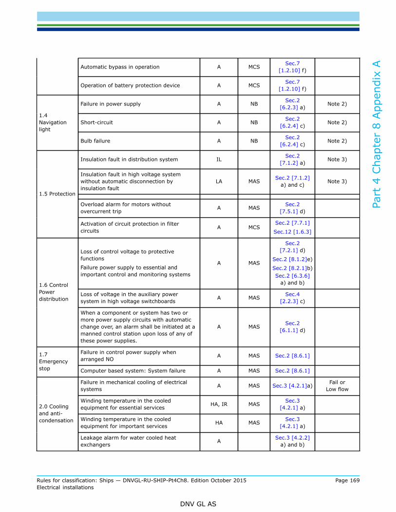
Part
4 C
hapt
er 8
App
endi
x A
Rules for classification: Ships — DNVGL-RU-SHIP-Pt4Ch8. Edition October 2015 Page 169Electrical installations
DNV GL AS
Automatic bypass in operation A MCS Sec.7[1.2.10] f)
Operation of battery protection device A MCS Sec.7[1.2.10] f)
Failure in power supply A NB Sec.2[6.2.3] a) Note 2)
Short-circuit A NB Sec.2[6.2.4] c) Note 2)
1.4Navigationlight
Bulb failure A NB Sec.2[6.2.4] c) Note 2)
Insulation fault in distribution system IL Sec.2[7.1.2] a) Note 3)
Insulation fault in high voltage systemwithout automatic disconnection byinsulation fault
LA MAS Sec.2 [7.1.2]a) and c) Note 3)
Overload alarm for motors withoutovercurrent trip A MAS Sec.2
[7.5.1] d)
1.5 Protection
Activation of circuit protection in filtercircuits A MCS
Sec.2 [7.7.1]
Sec.12 [1.6.3]
Loss of control voltage to protectivefunctions
Failure power supply to essential andimportant control and monitoring systems
A MAS
Sec.2[7.2.1] d)
Sec.2 [8.1.2]e)
Sec.2 [8.2.1]b)Sec.2 [6.3.6]
a) and b)
Loss of voltage in the auxiliary powersystem in high voltage switchboards A MAS Sec.4
[2.2.3] c)
1.6 ControlPowerdistribution
When a component or system has two ormore power supply circuits with automaticchange over, an alarm shall be initiated at amanned control station upon loss of any ofthese power supplies.
A MAS Sec.2[6.1.1] d)
Failure in control power supply whenarranged NO A MAS Sec.2 [8.6.1] 1.7
Emergencystop Computer based system: System failure A MAS Sec.2 [8.6.1]
Failure in mechanical cooling of electricalsystems A MAS Sec.3 [4.2.1]a) Fail or
Low flow
Winding temperature in the cooledequipment for essential services HA, IR MAS Sec.3
[4.2.1] a)
Winding temperature in the cooledequipment for important services HA MAS Sec.3
[4.2.1] a)
2.0 Coolingand anti-condensation
Leakage alarm for water cooled heatexchangers A Sec.3 [4.2.2]
a) and b)
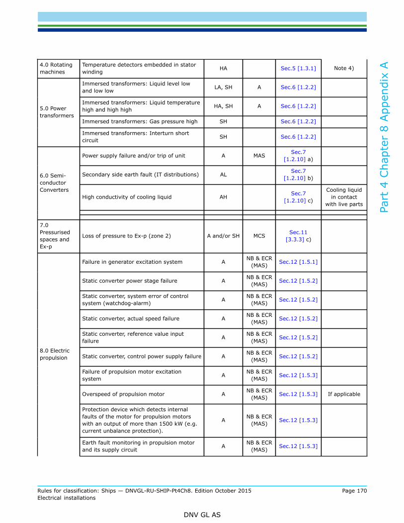
Part
4 C
hapt
er 8
App
endi
x A
Rules for classification: Ships — DNVGL-RU-SHIP-Pt4Ch8. Edition October 2015 Page 170Electrical installations
DNV GL AS
4.0 Rotatingmachines
Temperature detectors embedded in statorwinding HA Sec.5 [1.3.1] Note 4)
Immersed transformers: Liquid level lowand low low LA, SH A Sec.6 [1.2.2]
Immersed transformers: Liquid temperaturehigh and high high HA, SH A Sec.6 [1.2.2]
Immersed transformers: Gas pressure high SH Sec.6 [1.2.2]
5.0 Powertransformers
Immersed transformers: Interturn shortcircuit SH Sec.6 [1.2.2]
Power supply failure and/or trip of unit A MAS Sec.7[1.2.10] a)
Secondary side earth fault (IT distributions) AL Sec.7[1.2.10] b)
High conductivity of cooling liquid AH Sec.7[1.2.10] c)
Cooling liquidin contact
with live parts
6.0 Semi-conductorConverters
7.0Pressurisedspaces andEx-p
Loss of pressure to Ex-p (zone 2) A and/or SH MCS Sec.11[3.3.3] c)
Failure in generator excitation system A NB & ECR(MAS) Sec.12 [1.5.1]
Static converter power stage failure A NB & ECR(MAS) Sec.12 [1.5.2]
Static converter, system error of controlsystem (watchdog-alarm) A NB & ECR
(MAS) Sec.12 [1.5.2]
Static converter, actual speed failure A NB & ECR(MAS) Sec.12 [1.5.2]
Static converter, reference value inputfailure A NB & ECR
(MAS) Sec.12 [1.5.2]
Static converter, control power supply failure A NB & ECR(MAS) Sec.12 [1.5.2]
Failure of propulsion motor excitationsystem A NB & ECR
(MAS) Sec.12 [1.5.3]
Overspeed of propulsion motor A NB & ECR(MAS) Sec.12 [1.5.3] If applicable
Protection device which detects internalfaults of the motor for propulsion motorswith an output of more than 1500 kW (e.g.current unbalance protection).
A NB & ECR(MAS) Sec.12 [1.5.3]
8.0 Electricpropulsion
Earth fault monitoring in propulsion motorand its supply circuit A NB & ECR
(MAS) Sec.12 [1.5.3]

Part
4 C
hapt
er 8
App
endi
x A
Rules for classification: Ships — DNVGL-RU-SHIP-Pt4Ch8. Edition October 2015 Page 171Electrical installations
DNV GL AS
Insufficient power for propulsion A NB Sec.12[1.6.2] b)
Pre warning alarms for shut down caused bysafety functions (as far as possible) A NB Sec.12
[1.6.3] c)
Cooling medium temperature HA NB[1.6.3] -
Monitoringand alarms
Note 5)
Winding temperature of all propulsiongenerators and motors HA NB
[1.6.3] -Monitoringand alarms
Note 5)
Loss of flow of primary and secondarycoolants LA/A NB Sec.12 [1.6.3]
Note 5) and
Note 7)
Bearing temperature HA NB Sec.12 [1.6.3]
Lubricating monitoring LA NB[1.6.3] -
Monitoringand alarms
Note 5)
Monitoring of shaft locking device IR MAS Sec.12 [1.6.3]
Water-air heat exchanger leakage A NB Sec.12[1.6.4] f) Note 5)
Earth fault for main propulsion circuits A NB Sec.12[1.6.4] f) Note 5)
Earth fault for excitation circuits A NB Sec.12[1.6.4] f)
Note 5) and
Note 6)
Miscellaneous components A Sec.12[1.6.4] f)
Note 5) and
Note 8)

Part
4 C
hapt
er 8
App
endi
x A
Rules for classification: Ships — DNVGL-RU-SHIP-Pt4Ch8. Edition October 2015 Page 172Electrical installations
DNV GL AS
IL = Local indication (presentation of values), in vicinity of the monitored engine component or systemIR = Remote indication (presentation of values), in engine control room or another centralized control station such
as the local platform/manoeuvring consoleA = Alarm activated for logical valueLA = Alarm for low valueHA = Alarm for high valueSH = Shut down with corresponding alarm. May be manually (request for shut down) or automatically executed if
not explicitly stated above.NB = Navigation bridgeMAS = Main alarm systemMCS = Main control station
Notes:
1) Applicable for cooling equipment in environmentally controlled spaces, where equipment with reduced ambienttemperature tolerance is installed.
2) Alarms/indication required in WH only3) Insulated or high resistance earthed systems4) Applicable if rated output > 5000kW and all high voltage motors and all propulsion motors5) Critical alarms shall be relayed to the navigation bridge and displayed with separate warnings separated from group
alarms.6) This may be omitted in circuits of brushless excitation systems and for machines rated less than 500 kW)7) For machines and semi-conductor converters having closed cooling method with a heat exchanger, when this flow is
not caused by the propulsion motor itself.8) Fuses for filter units or for other components where fuse failure is not evident.

DNV GLDriven by our purpose of safeguarding life, property and the environment, DNV GL enablesorganizations to advance the safety and sustainability of their business. We provide classification andtechnical assurance along with software and independent expert advisory services to the maritime,oil and gas, and energy industries. We also provide certification services to customers across a widerange of industries. Operating in more than 100 countries, our 16 000 professionals are dedicated tohelping our customers make the world safer, smarter and greener.
SAFER, SMARTER, GREENER