dnvgl-ru-uwt-pt4ch8 electrical installations€¦ · · 2015-12-15exceptions may be allowed in...
TRANSCRIPT
The content of this service document is the subject of intellectual property rights reserved by DNV GL AS ("DNV GL"). The useraccepts that it is prohibited by anyone else but DNV GL and/or its licensees to offer and/or perform classification, certificationand/or verification services, including the issuance of certificates and/or declarations of conformity, wholly or partly, on thebasis of and/or pursuant to this document whether free of charge or chargeable, without DNV GL's prior written consent.DNV GL is not responsible for the consequences arising from any use of this document by others.
The electronic pdf version of this document, available free of chargefrom http://www.dnvgl.com, is the officially binding version.
DNV GL AS
RULES FOR CLASSIFICATION
Underwater technologyEdition December 2015
Part 4 Machinery and systems
Chapter 8 Electrical installations
FOREWORD
DNV GL rules for classification contain procedural and technical requirements related to obtainingand retaining a class certificate. The rules represent all requirements adopted by the Society asbasis for classification.
© DNV GL AS December 2015
Any comments may be sent by e-mail to [email protected]
If any person suffers loss or damage which is proved to have been caused by any negligent act or omission of DNV GL, then DNV GL shallpay compensation to such person for his proved direct loss or damage. However, the compensation shall not exceed an amount equal to tentimes the fee charged for the service in question, provided that the maximum compensation shall never exceed USD 2 million.
In this provision "DNV GL" shall mean DNV GL AS, its direct and indirect owners as well as all its affiliates, subsidiaries, directors, officers,employees, agents and any other acting on behalf of DNV GL.
Part
4 C
hapt
er 8
Cha
nges
- c
urre
nt
Rules for classification: Underwater technology — DNVGL-RU-UWT-Pt4Ch8. Edition December 2015 Page 3Electrical installations
DNV GL AS
CURRENT – CHANGES
This is a new document.
The rules enter into force 1 July 2016.
Part
4 C
hapt
er 8
Con
tent
s
Rules for classification: Underwater technology — DNVGL-RU-UWT-Pt4Ch8. Edition December 2015 Page 4Electrical installations
DNV GL AS
CONTENTS
Current – changes...................................................................................................... 3
Section 1 General....................................................................................................... 51 Introduction............................................................................................52 References.............................................................................................. 53 Procedural requirements........................................................................ 5
Section 2 Design principles........................................................................................ 71 General principles...................................................................................72 Materials and insulation......................................................................... 73 Supply systems.......................................................................................84 Voltages and frequencies....................................................................... 85 Protective measures............................................................................... 96 Storage batteries and battery chargers................................................ 127 Special requirements for lead batteries................................................158 Special requirements for lithium based (e.g. lithium ion) batteries.......159 Battery chargers...................................................................................16
Section 3 Electrical penetrations in pressure hull walls and underwater plugconnections...........................................................................................................18
1 Design...................................................................................................182 Type approval program for electrical pressure hull penetrations and
plug connections.................................................................................. 18
Section 4 Electrical machines...................................................................................211 Requirements........................................................................................21
Part
4 C
hapt
er 8
Sec
tion
1
Rules for classification: Underwater technology — DNVGL-RU-UWT-Pt4Ch8. Edition December 2015 Page 5Electrical installations
DNV GL AS
SECTION 1 GENERAL
1 Introduction
1.1 Application
1.1.1 The following rules apply to the general aspects of electrical systems which are needed to operateunderwater systems.
1.1.2 The requirements of this chapter shall be regarded as supplementary to those given for main class inSHIP Pt.4 Ch.8 and the individual chapters for underwater systems in Pt.5, where applicable.
1.2 The electrical equipment and installations, including power supply arrangements, shall be constructed andinstalled to operate satisfactorily under all environmental conditions for which the underwater system isdesigned. Reference is given to Pt.3 Ch.3 Sec.2.
2 ReferencesThe documents to be submitted to the Society for approval and the initial tests and trials are stated in Pt.5Ch.1 to Ch.9.The necessary markings also for electrical components are summarized in Pt.4 Ch.1 Sec.2.Recognised production standards include those provided by the International Electrotechnical Commission(IEC).The following codes and standards are applicable:
— RU SHIP Pt.4 Ch.8— relevant IEC equipment construction and design standards referred to— IMCA D 045, R015 Code of practice for the safe use of electricity underwater.
3 Procedural requirements
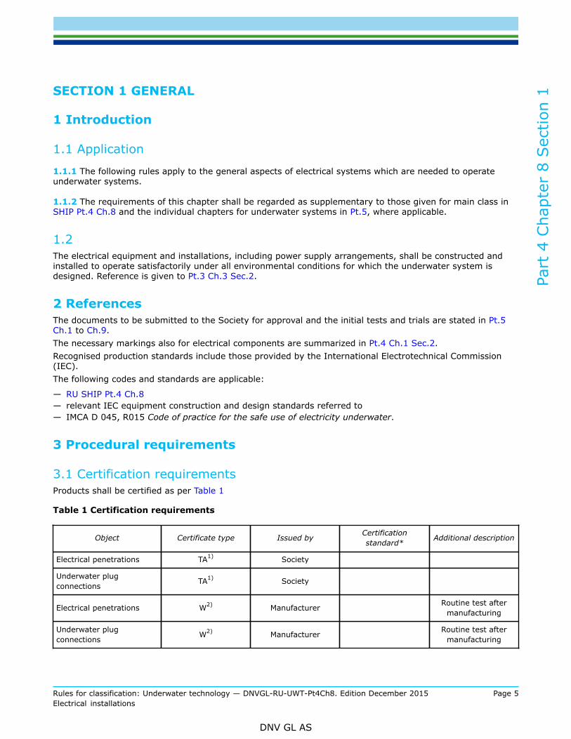
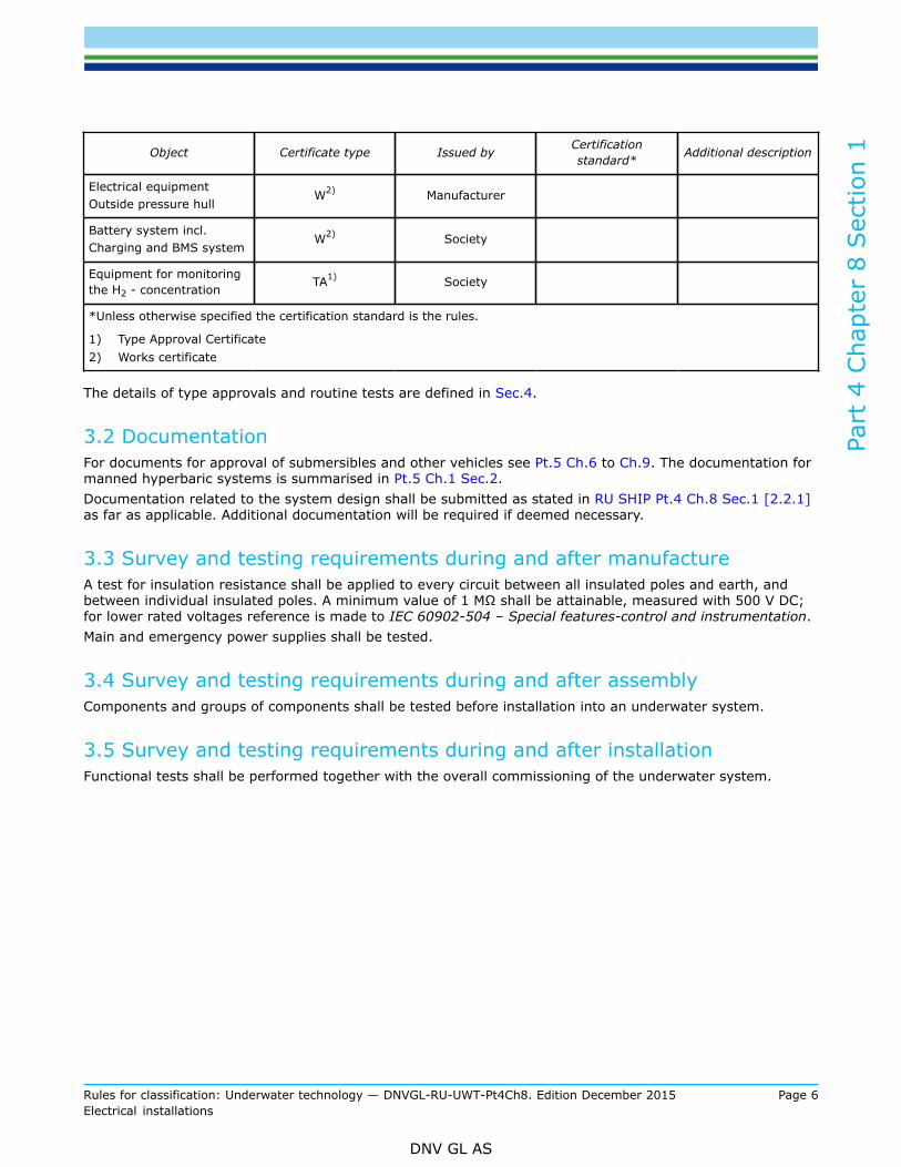
3.1 Certification requirementsProducts shall be certified as per Table 1
Table 1 Certification requirements
Object Certificate type Issued by Certificationstandard* Additional description
Electrical penetrations TA1) Society
Underwater plugconnections TA1) Society
Electrical penetrations W2) Manufacturer Routine test aftermanufacturing
Underwater plugconnections W2) Manufacturer Routine test after
manufacturing
Part
4 C
hapt
er 8
Sec
tion
1
Rules for classification: Underwater technology — DNVGL-RU-UWT-Pt4Ch8. Edition December 2015 Page 6Electrical installations
DNV GL AS
Object Certificate type Issued by Certificationstandard* Additional description
Electrical equipmentOutside pressure hull
W2) Manufacturer
Battery system incl.Charging and BMS system
W2) Society
Equipment for monitoringthe H2 - concentration TA1) Society
*Unless otherwise specified the certification standard is the rules.
1) Type Approval Certificate2) Works certificate
The details of type approvals and routine tests are defined in Sec.4.
3.2 DocumentationFor documents for approval of submersibles and other vehicles see Pt.5 Ch.6 to Ch.9. The documentation formanned hyperbaric systems is summarised in Pt.5 Ch.1 Sec.2.Documentation related to the system design shall be submitted as stated in RU SHIP Pt.4 Ch.8 Sec.1 [2.2.1]as far as applicable. Additional documentation will be required if deemed necessary.
3.3 Survey and testing requirements during and after manufactureA test for insulation resistance shall be applied to every circuit between all insulated poles and earth, andbetween individual insulated poles. A minimum value of 1 MΩ shall be attainable, measured with 500 V DC;for lower rated voltages reference is made to IEC 60902-504 – Special features-control and instrumentation.Main and emergency power supplies shall be tested.
3.4 Survey and testing requirements during and after assemblyComponents and groups of components shall be tested before installation into an underwater system.
3.5 Survey and testing requirements during and after installationFunctional tests shall be performed together with the overall commissioning of the underwater system.
Part
4 C
hapt
er 8
Sec
tion
2
Rules for classification: Underwater technology — DNVGL-RU-UWT-Pt4Ch8. Edition December 2015 Page 7Electrical installations
DNV GL AS
SECTION 2 DESIGN PRINCIPLES
1 General principles
1.1 All electrical systems and equipment shall be constructed and installed in such a way that they areserviceable and perform satisfactorily under the design conditions specified for the underwater system tominimize the risk of fire, explosion, electric shock and emissions of toxic gases. The operating parameters ofelectrical equipment are to conform to the requirements stated in RU SHIP Pt.4 Ch.8.Electrical circuits and equipment used in water shall be considered in each separate case and in accordancewith IMCA D 045, R015 Code of practice for the safe use of electricity underwater. Provisions shall be madeto reduce the possible fault currents, to which a person e.g. a diver can be exposed, to a harmless level.
1.2 Besides the essential consumers listed in SHIP Pt.4 Ch.8. the following items of electrical equipment alsocount as essential consumers:
— battery charging equipment for autonomous and independent submersibles with own charging device, e.g.generator
— battery room ventilators— acid circulation and cooling system— H2 measuring device— essential equipment for monitoring and treating breathing air— bilge and emergency bilge system— electrical installations for diving and buoyancy tanks, e.g. magnetic valves.
1.3 CablesCables for use in the outer area shall comply with RU SHIP Pt.4 Ch.8. All cables shall have an earthedbraiding or screen around the conductors and be equipped with an insulating outer sheet.The submerged cables shall be able to withstand an external hydrostatic pressure of 1.3 times the actualexternal pressure.Unless installed in pipes, electrical cables shall be readily accessible for visual inspection.Tensile loads shall not be transferred to the electrical cables.
2 Materials and insulation
2.1 The materials used in the construction of electrical machines, cables and apparatus shall be resistant to moistand salty sea air, seawater and oil vapours. They shall not be hygroscopic and shall be flame-retardant andself-extinguishing.In addition, materials installed inside decompression chambers and diving bells shall be approved foroperation in hyperbaric atmospheres and shall not liberate toxic gases or fumes under these conditions.
2.2 Materials with high tracking resistance shall be used for the supports of live parts.

Part
4 C
hapt
er 8
Sec
tion
2
Rules for classification: Underwater technology — DNVGL-RU-UWT-Pt4Ch8. Edition December 2015 Page 8Electrical installations
DNV GL AS
2.3 The creepage and clearance distances shall be dimensioned as appropriate for the appliance in accordancewith IEC. Generator circuit-breakers, pressure hull wall penetrations, under water plug connectors andappliances directly connected to the bus-bars shall be designed for the next higher nominal insulation rating.
2.4 Materials and insulations for electrical equipment used in water shall be agreed with the Society in eachsingle case.
2.5 All materials of submerged systems shall be such that their electrical and mechanical properties are notinfluenced by water absorption.
3 Supply systemsDetails of the main and emergency power supply systems of the different underwater systems are describedin the individual chapters of Pt.5.
3.1 Approved supply systems for underwater applicationDirect current and single-phase alternating current:
— 2 conductors insulated from the submersible's/vessel’s hull.
Three-phase alternating current:
— 3 conductors insulated from the submersible's/vessel’s hull.
3.2 Systems earthing is not permitted.
Guidance note:Exceptions may be allowed in the case of subsystems using isolating transformers and high resistance earthing
---e-n-d---of---g-u-i-d-a-n-c-e---n-o-t-e---
Exceptions may be allowed in the case of subsystems using isolating transformers and high resistanceearthing.
4 Voltages and frequencies
4.1 The maximum permissible voltages are the following, but deviating voltages for propulsion drives may beagreed with the Society:500 V:
— for permanently installed power systems— for power systems connected by socket outlets— for heating and galley equipment— for battery charging system
Part
4 C
hapt
er 8
Sec
tion
2
Rules for classification: Underwater technology — DNVGL-RU-UWT-Pt4Ch8. Edition December 2015 Page 9Electrical installations
DNV GL AS
— for external power supply.
250 V:
— for lighting systems and sockets for direct current and single-phase alternating current— mobile appliances with protective insulation and/or protective isolating transformers— machinery control and monitoring systems, vehicle control systems and vehicle safety systems— for battery charging system— for external power supply.
50 V (protective low voltage):
— for mobile appliances used in confined space conditions and in damp spaces, where appropriate usingprotective isolating transformers.
30 V:
— for all electrical equipment in diving bells and wet bells.Guidance note:The use of standard voltages and frequencies is recommended.
---e-n-d---of---g-u-i-d-a-n-c-e---n-o-t-e---
4.2 The emergency source of power and the emergency power distribution shall be capable of handling peakloads.
5 Protective measures
5.1 All electrical equipment shall be protected in accordance with SHIP Pt.4 unless otherwise stated in thefollowing.
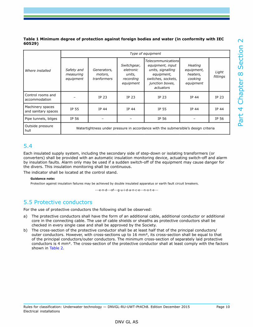
5.2 The minimum classes of protection stated in Table 1 shall be applied in manned underwater systems. Theclass of protection shall be maintained for the equipment as installed, even when in operation (heelingposition). In this context, the provision of shielding at the point of installation is deemed to be a protectivemeasure.
5.3 To protect divers against excessive contact voltages and electric shock, additional safety measures shall betaken to avoid or restrict dangerous fault currents. These measures shall be agreed with the Society in eachsingle case.
Part
4 C
hapt
er 8
Sec
tion
2
Rules for classification: Underwater technology — DNVGL-RU-UWT-Pt4Ch8. Edition December 2015 Page 10Electrical installations
DNV GL AS
Table 1 Minimum degree of protection against foreign bodies and water (in conformity with IEC60529)
Type of equipment
Where installed Safety andmeasuringequipment
Generators,motors,
tranformers
Switchgear,eletronic
units,recordingequipment
Telecommunicationsequipment, inputunits, signalling
equipment,switches, sockets,
junction boxes,actuators
Heatingequipment,
heaters,cooking
equipment
Lightfittings
Control rooms andaccommodation – IP 23 IP 23 IP 23 IP 44 IP 23
Machinery spacesand sanitary spaces IP 55 IP 44 IP 44 IP 55 IP 44 IP 44
Pipe tunnels, bilges IP 56 – – IP 56 – IP 56
Outside pressurehull Watertightness under pressure in accordance with the submersible’s design criteria
5.4 Each insulated supply system, including the secondary side of step-down or isolating transformers (orconverters) shall be provided with an automatic insulation monitoring device, actuating switch-off and alarmby insulation faults. Alarm only may be used if a sudden switch-off of the equipment may cause danger forthe divers. This insulation monitoring shall be continuous.The indicator shall be located at the control stand.
Guidance note:Protection against insulation failures may be achieved by double insulated apparatus or earth fault circuit breakers.
---e-n-d---of---g-u-i-d-a-n-c-e---n-o-t-e---
5.5 Protective conductorsFor the use of protective conductors the following shall be observed:
a) The protective conductors shall have the form of an additional cable, additional conductor or additionalcore in the connecting cable. The use of cable shields or sheaths as protective conductors shall bechecked in every single case and shall be approved by the Society.
b) The cross-section of the protective conductor shall be at least half that of the principal conductors/outer conductors. However, with cross-sections up to 16 mm², its cross-section shall be equal to thatof the principal conductors/outer conductors. The minimum cross-section of separately laid protectiveconductors is 4 mm². The cross-section of the protective conductor shall at least comply with the factorsshown in Table 2.
Part
4 C
hapt
er 8
Sec
tion
2
Rules for classification: Underwater technology — DNVGL-RU-UWT-Pt4Ch8. Edition December 2015 Page 11Electrical installations
DNV GL AS
Table 2 Cross-sections for protective conductors
Minimum cross-section of earthing conductorCross-section of outer conductor
[mm2] in insulated cables[mm2]
Separately laid[mm2]
0.5 to 4 equal to cross-section of outerconductor 4
> 4 to 16 equal to cross-section of outerconductor
equal to cross-section of outerconductor
> 16 to 35 16 16
> 35 to < 120 equal to half the cross-section ofthe outer conductor
equal to half the cross-section of theouter conductor
≥ 120 70 70
a) In the submersible's propulsion network, the dimensional design of the protective conductors shall bebased on the maximum possible short-circuit currents of the equipment concerned, the maximum breaktimes of the relevant protective elementsand a maximum temperature rise of the protective conductor of90°C.
b) The protective conductor shall be connected to the hull of the support vessel in a position where it caneasily be checked.
c) The connections of the protective conductors to the submersible shall be installed at locations which areeasily to check.
5.6 Special earthing requirements for manned hyperbaric systemsFor earthing the following shall be considered:
a) Manned hyperbaric systems shall be equipped with an earthing and potential equalizing system.Connections for external earthing shall be provided at all pressure chambers. Also in gas storage andfilling station, etc.
b) All metal parts of electrical installations – with the exception of live components – shall be earthed.The casings of electrical equipment mounted directly against the inside wall of pressure chambers areconsidered to be effectively earthed only if the contact surfaces are permanently free from rust, scaleand paint and the casings are fastened with at least two corrosion resistant screws secured to preventaccidental loosening. If these conditions are not met, earthing shall be effected by separate earthingconductors.
c) The connections of the potential equalization at the diving bell/wet bell shall be installed where it can bechecked easily. In an easily accessible position of the superstructure of the support vessel and on thediving bell/wet bell a connection point in the form of a connecting plate with preferably M 12 stud boltsshall be provided to which protective conductors can be connected without tools. This connection servesfor the compensation of the potential between the manned hyperbaric system and the platform mountedto.
d) The casings of electrical equipment in water are always to be earthed by an earthing conductor includedin the supply cable. Where this is not possible, casings mountedon the outside of the diving bell mayalso be provided with a separate external earth. In this case, however, the entire earth connection(connecting screws and earthing conductor) shall be provided corrosion-resistant.
e) The connections between the earthing conductor and the chamber and to the vessel's earth shall bemade with corrosion-resistant screw connections effectively safeguarded against accidental loosening.The dimensions of the screw connections shall be dimensioned according to the requisite cross-sectionsof the earth conductor to be connected and may not be used for other purposes.
Part
4 C
hapt
er 8
Sec
tion
2
Rules for classification: Underwater technology — DNVGL-RU-UWT-Pt4Ch8. Edition December 2015 Page 12Electrical installations
DNV GL AS
f) Machines and devices which are mounted on insulating vibration dampers shall be earthed by flexiblecables, wires or stranded copper straps.
g) Earth connections shall be accessible for maintenance and inspection. Wherever possible, they shallbe marked. Earthing conductors in multi-core cables shall be marked green and yellow, at least at theterminals.
h) Earthing conductors shall be provided with corrosion protection compatible with their place ofinstallation.
i) Copper earthing conductors are subject to the following minimum cross-sections:
— external connections on support ship and water: 10 mm²— external connections inside chambers and living compartments: 6 mm²— separate earthing conductors inside switchgear and casings: 4 mm²— Earthing conductors in multi-core cables up to a conductor cross-section of 16 mm² shall correspond
to the cross-section of the main conductor, subject to a minimum of 1 mm²— earthing conductors in multi-core cables with a conductor cross-section of more than 16 mm² equal
to at least half that of the main conductor
If other materials are used, the minimum cross-section shall be determined by the ratio of the electricalconductivity of these materials to the electrical conductivity of copper.
j) Cable sheaths and armouring are not to be used as earthing conductors.
In the water, all metal enclosures shall be earthed by means of a copper earth conductor incorporated in thesupply cable, with cross-section at least of the same size as the supply conductors and not less than 1 mm².For cables having metal wire braid or armour this may alternatively be used as earth conductor, provided thatthe braiding cross section is sufficient.
5.7 Special earthing requirements for submersiblea) Machines and appliances mounted on insulated vibration dampers shall be earthed with mobile cables,
conductors or braided copper leads.b) The connections of the protective conductors to the submersible shall be installed at locations which are
easily to check.c) At the superstructure resp. at the hull of the submersible a possibility for connection in the form of
a connecting plate with stud bolt, preferably M 12, to which protective conductors can be connectedwithout the use of tools shall be provided at an easily accessible position.This connection shall serve as compensation of potential between the recovered submersible and thesupport vessel.
6 Storage batteries and battery chargers
6.1 Storage batteries shall be rated such as to be capable of supplying the consumers during the period specifiedin accordance with the power balance, when charged to 80% of their rated capacity.
6.2 At the end of the supply period the voltage in the storage battery resp. in the consumers shall at least reachthe values quoted in RU SHIP Pt.4 Ch.8 Sec.2 [9.4].

Part
4 C
hapt
er 8
Sec
tion
2
Rules for classification: Underwater technology — DNVGL-RU-UWT-Pt4Ch8. Edition December 2015 Page 13Electrical installations
DNV GL AS
6.3 Approved storage batteries are lead-acid storage batteries with diluted sulphuric acid as electrolyte and steelstorage batteries with nickel-cadmium cells and diluted potassium hydroxide as electrolyte.
6.4 Further types of batteries may be approved under consideration and test of the following points:
— resistance to short circuits— fuse elements at occurring short circuits— electrical monitoring elements— fire risk/fire behaviour including consequences on adjacent cells or components— special requirements for the installation location— suitability of the used belonging electrical components— integration in the electrical plant including switch gears— charging devices and automation system for charging— Release of flammable and/ or toxic vapour and gas.
An risk analysis shall be provided.Final installation requirements to be agreed with the Society.If no special measures are taken only lithium iron phosphate type batteries up to 50 Wh in total may beinstalled within an atmospheric manned compartment. (see also [8])Final acceptance to be agreed with the Society.
6.5 Storage batteries shall be designed such as to retain their undisturbed function at inclinations of up to 22.5°and such that for inclinations of up to 45° electrolyte will not leak. Cells without covers are not admissible.
6.6 The casing shall be resistant to electrolytes, mineral oils and cleaning agents, as well as to corrosion due tosaline mist. Glass and readily flammable materials are not approved as materials for casings.
6.7 In the case of storage batteries containing liquid electrolyte it shall be possible to check the electrolyte level.The maximum admissible electrolyte level shall be marked.
6.8 Lead and alkaline storage batteries shall not be accommodated in the same space or be placed in directproximity to each other.
6.9 Where the installed batteriescontain an energy greater than 50 kWh or more, the battery shall be dividedinto smaller battery units so that at least safe operation of the submersible is still possible in the event of afault.Special attention has to be paid to lithium based batteries.
Part
4 C
hapt
er 8
Sec
tion
2
Rules for classification: Underwater technology — DNVGL-RU-UWT-Pt4Ch8. Edition December 2015 Page 14Electrical installations
DNV GL AS
6.10 It shall be possible to bridge damaged cells with measures on board if they are located within the pressurehull. The use of rigid interconnection links between batteries shall be avoided.
6.11 The weight of the biggest transportable unit shall not exceed 100 kg.
6.12 The rating data of the storage batteries shall be indicated on rating plates.Storage batteries shall be serviced and operated in accordance with manufacturers' instructions.
6.13 Storage batteries providing a power source for electric propeller drives and/or the submersible's powernetwork shall be accommodated in special battery spaces or containers. It is necessary to ensure that thestorage batteries are accessible for cell replacement, repairs and maintenance.
6.14 Measures shall be taken to ensure that neither the crew nor the operational equipment can be endangered byemissions of electrolyte fumes.
6.15 A sign shall be mounted at the entrance of battery spaces pointing out that only insulated tools shall be usedinside and conductive objects like keys, ballpoint pens, watches with conductive watch straps shall be takenoff. Explosion hazard shall be pointed out.
6.16 Storage batteries shall be installed in such a way that mechanical damage is as far as possible excluded. Safeoperation under the environmental conditions stated in Pt.3 Ch.3 Sec.2 shall be ensured and the discharge ofelectrolyte shall be prevented.Suitable measures, e.g. provision of plastic trays or flexible rubber bags, shall be taken to prevent electrolytefrom entering the battery space bilges in the event of mechanical damage to individual battery cells.
6.17 Battery housings shall be provided with adequate and unobstructed ventilation to open air in accordancewith RU SHIP Pt.4 Ch.8 Sec.2 [9.4], so that an accumulation of generated flammable gases is avoided. Theventilation intake shall be fed into the lower parts and the outlet arranged in the uppermost part of thehousing.The location of rechargeable battery installations are considered as potentially hazardous area and shall becarefully considered during the conceptual design of the underwater system lay-out early in the project, incompliance with RU SHIP Pt.4 Ch.8 Sec.2 [9.4].

Part
4 C
hapt
er 8
Sec
tion
2
Rules for classification: Underwater technology — DNVGL-RU-UWT-Pt4Ch8. Edition December 2015 Page 15Electrical installations
DNV GL AS
7 Special requirements for lead batteries
7.1 Battery spaces shall be arranged and ventilated to prevent the accumulation of ignitable gas mixtures.
7.2 The quantity of air to be aspirated and exhausted during charging shall be so calculated, that the lowerexplosion limit for a hydrogen air mixture will not be exceeded. H2-monitors permanently mounted atsuitable points shall measure the gas concentration in the battery space, the exhaust system and, wherenecessary, in other spaces within the submersible.If the H2 concentration reaches and exceeds a level equivalent to 35 % of the lower explosion limit (LEL),this shall automatically release a visual and audible alarm at a central monitoring station. Equipment formonitoring the H2 - concentration shall be type approved.
7.3 Battery spaces shall contain no other electrical appliances apart from the storage batteries themselves.Lights, fuses (single voltage measuring device) and measuring devices for H2 concentration may be installedif they are in accordance with the requirements for an atmosphere containing H2 (see publication IEC 60079).
8 Special requirements for lithium based (e.g. lithium ion) batteries
8.1 All hazards shall be described in a safety description. Safety precautions mitigating the identified risks shallbe included.The safety description shall cover all potential hazards represented by the type (chemistry) of battery and atleast cover:
— potential gas development (toxic, flammable, corrosive)— fire risk— explosion risk— necessary detection and alarm systems (gas detection, fire detection etc.) and ventilation for the battery
space— a suitable fire extinguish method— internal cell failure/thermal runaway— internal and external short circuit— external heating/fire.
8.2 The battery system shall have an integrated battery management system (BMS)
8.3 For following parameters shall be monitored in minimum, i.e. protections functions shall be provided:
— single cell voltage

Part
4 C
hapt
er 8
Sec
tion
2
Rules for classification: Underwater technology — DNVGL-RU-UWT-Pt4Ch8. Edition December 2015 Page 16Electrical installations
DNV GL AS
— overvoltage— undervoltage— overcurrent— temperature limits, if necessary because of the used chemistry two sets of temperature limits shall be
implemented for charging and discharging— in case the risk assessment shows, that a disballanced battery system will cause hazardous situations, the
cell balancing function shall be part of the BMS— deep discharge— overcharge— tripping of battery breakers/contactor— high cell pressure or opening of cell safety vent or venting mechanism.
8.4 A risk assessment shall be carried out in any case.
8.5 Compliance with UN 38.3 shall be proven by an international recognised laboratory.
8.6 Reference is made to the following standards:
— IEC 62620 (performance test)— IEC 62619 and 62133 (safety functions)— UN 38.3— IEC 61508.
9 Battery chargers
9.1 Battery chargers shall be rated such that the maximum admissible charging currents cannot be exceeded.
9.2 The power demand of the consumers shall be taken into account when selecting the battery chargers.
9.3 The battery chargers shall be rated such that the tolerances of the limited characteristics and constantcharacteristics respectively are adhered to irrespective of external disturbance effects.
9.4 Battery chargers shall cut out automatically in case of:
— failure of the battery space ventilation (if an ignitable gas mixture may be created)— excessive temperature of charging generator/battery charger— overtemperature of the electrolyte (if a temperature control of the single cells is provided).
Part
4 C
hapt
er 8
Sec
tion
2
Rules for classification: Underwater technology — DNVGL-RU-UWT-Pt4Ch8. Edition December 2015 Page 17Electrical installations
DNV GL AS
9.5 For lead batteries the following shall additionally be considered:
— If during charging simultaneously consumers are fed, the maximum charging voltage shall not exceed120% of the rated voltage.
— Preferably chargers with IU or IUI resp. IUW characteristics shall be employed.— Charging devices have to cut off automatically, if the H2 concentration is too high, e.g. 60% LEL.
Part
4 C
hapt
er 8
Sec
tion
3
Rules for classification: Underwater technology — DNVGL-RU-UWT-Pt4Ch8. Edition December 2015 Page 18Electrical installations
DNV GL AS
SECTION 3 ELECTRICAL PENETRATIONS IN PRESSURE HULL WALLSAND UNDERWATER PLUG CONNECTIONS
1 DesignFor the design the following shall be considered:
— the design shall be done for 1.1 times the collapse diving pressure CDP— pressure hull penetrations shall be gas and watertight. Their tightness shall be guaranteed even if the
connected cables have been damaged or shorn off— electrical penetrations are not to be used for the passage of other systems— the positive and the negative conductors from a power source are not to pass through the same
penetrating device at the pressure hull wall— electrical conductors within the penetrating device shall be of solid material.
2 Type approval program for electrical pressure hull penetrationsand plug connections
2.1 Test requirements2.1.1 GeneralType-testing is performed, on application, at the manufacturer's works and comprises at least the followingindividual tests:
— hydraulic pressure test— gas tightness test— high voltage test— measurement of insulation resistance— visual check
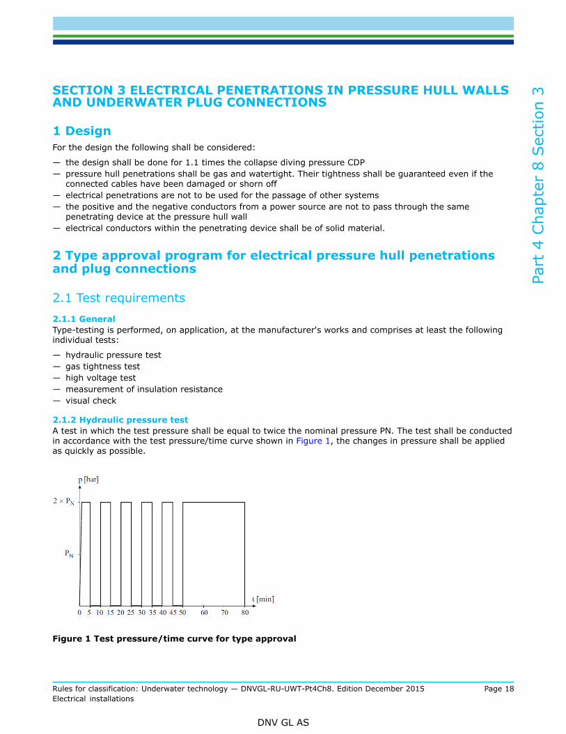
2.1.2 Hydraulic pressure testA test in which the test pressure shall be equal to twice the nominal pressure PN. The test shall be conductedin accordance with the test pressure/time curve shown in Figure 1, the changes in pressure shall be appliedas quickly as possible.
Figure 1 Test pressure/time curve for type approval
Part
4 C
hapt
er 8
Sec
tion
3
Rules for classification: Underwater technology — DNVGL-RU-UWT-Pt4Ch8. Edition December 2015 Page 19Electrical installations
DNV GL AS
2.1.3 Gas tightness testFor penetrations pressurized with gas a gas tightness test shall be performed.A test with shorn, open cable ends. This test may be performed under air or alternatively under helium. Thetest pressure shall be 2 times the nominal pressure of the component PN for air and 1,5 times the nominalpressure of the component PN for helium. The leakage rate shall be specified by the manufacturer and to beapproved by the Society.In all pressure and tightness tests on pressure hull wall penetrations, the pressure shall be applied in eachcase from the pressure side of the wall penetration.During the pressure and tightness test, the penetration shall be loaded with the rated current in allconductors.
2.1.4 High voltage testA test at an AC voltage of 1000 V plus twice the rated voltage. This test is performed at the rated frequencyand shall be carried out for 1 minute in each case between all the conductors mutually and between theconductors and the casing. The test is performed in the disconnected state. The sealing of the connectorshells and the like is permitted to the degree stipulated by the manufacturer in the relevant data sheet.
2.1.5 Measurement of insulation resistanceThe minimum value of the insulation resistance between the conductors mutually and between theconductors and the casing shall be 5 MΩ for the type test, for periodic classification surveys the minimumvalue shall be 2 MΩ.The insulation resistance shall be measured with an instrument using 500 V DC. For lower rated voltageapplication reference is made to IEC 60902-504 – Special features-control and instrumentation.With wet plug connections, the minimum insulation resistance is also to be measured after the connectionhas been made once in saltwater.
2.1.6 Visual checkCheck against manufacturer's documentation.
2.2 Individual test after the manufacturing (routine test)Each manufactured electrical pressure hull wall penetration and each plug connection shall be subjected toroutine inspection after manufacturing by the manufacturer, see also Sec.1 [3].This inspection comprises the following tests:
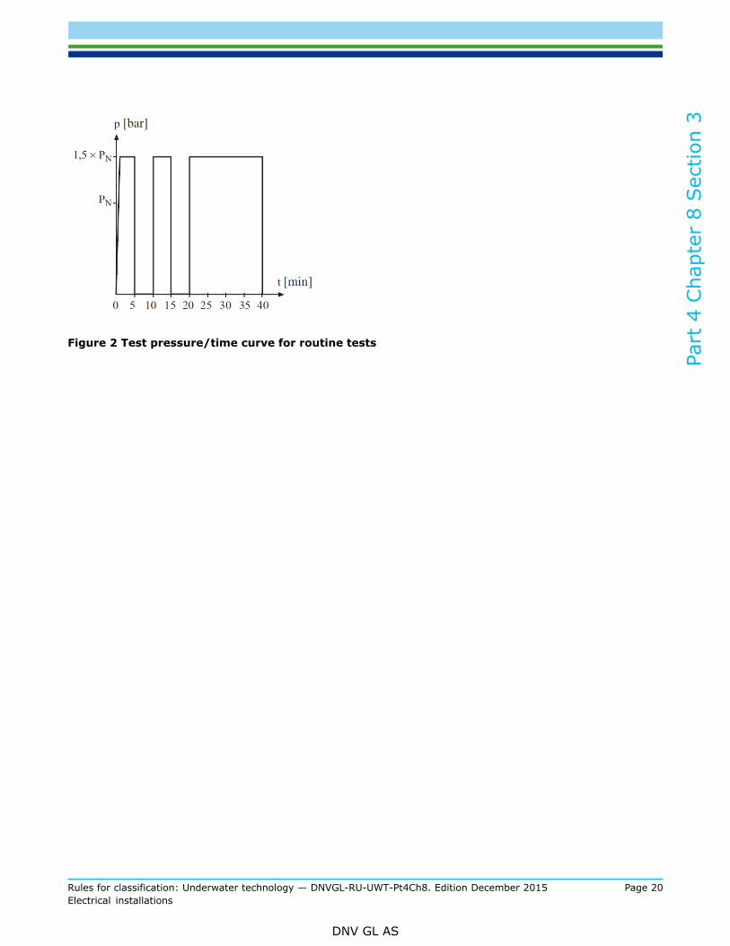
— hydraulic pressure test at the manufacturer in accordance with Figure 2 at 1.5 times the nominal pressureof the component PN and at the overall test with test diving pressure TDP, if applicable.
— high-voltage test— measurement of insulation resistance
A works certificate (W) shall be issued covering the inspection.
Part
4 C
hapt
er 8
Sec
tion
3
Rules for classification: Underwater technology — DNVGL-RU-UWT-Pt4Ch8. Edition December 2015 Page 20Electrical installations
DNV GL AS
Figure 2 Test pressure/time curve for routine tests

Part
4 C
hapt
er 8
Sec
tion
4
Rules for classification: Underwater technology — DNVGL-RU-UWT-Pt4Ch8. Edition December 2015 Page 21Electrical installations
DNV GL AS
SECTION 4 ELECTRICAL MACHINES
1 Requirements
1.1 Electrical machines
1.1.1 Electrical machines shall conform to RU SHIP Pt.4 Ch.8.
1.1.2 All electrical penetrations in pressure containing structures shall be purpose designed, certified andshall be arranged with separate fittings.
1.1.3 Penetrations in pressure vessels shall be gas and water-tight, as applicable, even in the event ofdamage to the connecting cables. (see Sec.3 [2])
1.1.4 For the windings of electrical machines in submersibles at least isolation class F shall be provided.
1.1.5 In addition to the tests stipulated in RU SHIP Pt.4 Ch.8 Sec.5 [3] the following electrical machines shallbe tested in the presence of a surveyor:
— generators and motors for electric propeller drives— motors for steering gear drives and windlasses— all other motors driving machines and equipment necessary to the safety and manoeuvrability of the
submersible.
1.2 Generators and electric propeller motors
1.2.1 Generators and all electric propeller motors shall to be equipped with a standstill heating system.
1.2.2 An automatic limitation of the performance of the driving motors has to secure that the board main isnot overloaded.
1.2.3 The reverse power for reversing, reduction and shut-off shall be considered and shall be limited topermissible maximum values.
1.3 Electric propeller drives
1.3.1 Machines for electric propeller drives rated at more than 100 kW shall be equipped with monitoringdevices in accordance with SHIP Pt.4 Ch.8.
1.3.2 If direct current motors are used, energizing current circuits where the failure may endanger theoperation shall be protected against short circuit.

DNV GLDriven by our purpose of safeguarding life, property and the environment, DNV GL enablesorganizations to advance the safety and sustainability of their business. We provide classification andtechnical assurance along with software and independent expert advisory services to the maritime,oil and gas, and energy industries. We also provide certification services to customers across a widerange of industries. Operating in more than 100 countries, our 16 000 professionals are dedicated tohelping our customers make the world safer, smarter and greener.
SAFER, SMARTER, GREENER