diy install of vrsf turbo inlets - vr-speed.com · diy install of vrsf turbo inlets ... 3. jack and...
TRANSCRIPT

DIY Install of VRSF Turbo Inlets
DISCLAIMER: This DIY is intended to
document my own DIY procedure for a
2009 e92 335i x-drive (335xi) with
automatic transmission and base trim
(no sport package). I am not responsible
for any damage caused to your vehicle
or injury caused to yourself or others
resulting from the following of this
tutorial. Use this procedure at your own
risk.
Further, I am not an employee or
affiliate of VRSF, I am merely a car
enthusiast/hobby mechanic that
appreciates the quality products and
support they provide our BMW
community.
Lastly, the process involved and/or steps
required may (most certainly will) vary as no two cars are the same. If there inaccuracies or steps missing let me
know and I'll update the DIY.
Tools:
1. Metric Socket Set (Specifically need 8mm, 10mm, 11mm, 13mm, 16mm, 17mm, & 18mm)
2. Drop light
3. Jack and jack stands
4. Wheel chocks or wood blocks.
5. T25 and T30 Torx Bits
6. Hex/Allen wrenches
Prep:
1) Disconnect the Battery – Battery is in the trunk on the right-hand side behind the removable panel. You need a
10mm socket. Loosen and disconnect the negative terminal (connected to the black wire on the terminal
closest to the rear bumper.)
2) Loosen Front Wheel Lugs – you will be taking the wheels off when
front is raised.
3) Raise front of car – Chock rear wheels (do not rely solely on e-brake –
they can fail) roll your jack under the front end jack point (shown in
picture to the right). Place Jack stands under front-end jack pads and
remove wheels.
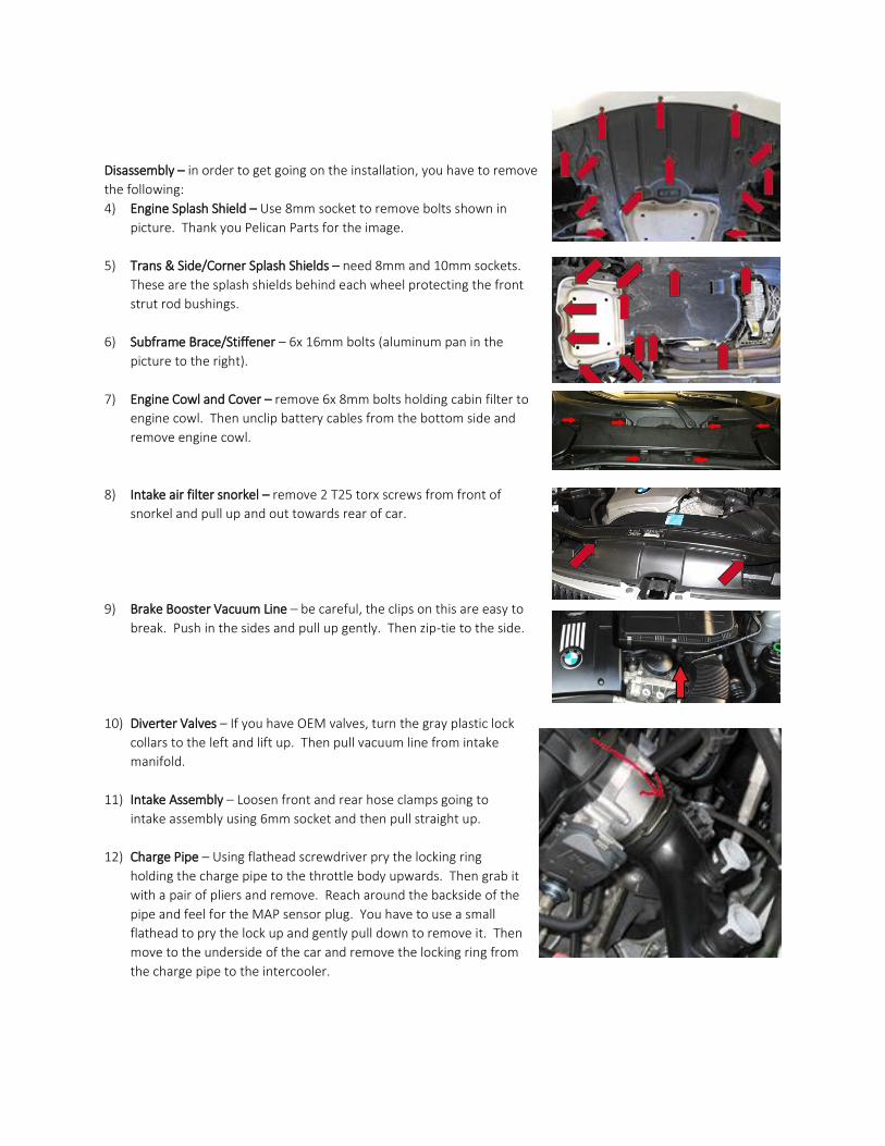
Disassembly – in order to get going on the installation, you have to remove
the following:
4) Engine Splash Shield – Use 8mm socket to remove bolts shown in
picture. Thank you Pelican Parts for the image.
5) Trans & Side/Corner Splash Shields – need 8mm and 10mm sockets.
These are the splash shields behind each wheel protecting the front
strut rod bushings.
6) Subframe Brace/Stiffener – 6x 16mm bolts (aluminum pan in the
picture to the right).
7) Engine Cowl and Cover – remove 6x 8mm bolts holding cabin filter to
engine cowl. Then unclip battery cables from the bottom side and
remove engine cowl.
8) Intake air filter snorkel – remove 2 T25 torx screws from front of
snorkel and pull up and out towards rear of car.
9) Brake Booster Vacuum Line – be careful, the clips on this are easy to
break. Push in the sides and pull up gently. Then zip-tie to the side.
10) Diverter Valves – If you have OEM valves, turn the gray plastic lock
collars to the left and lift up. Then pull vacuum line from intake
manifold.
11) Intake Assembly – Loosen front and rear hose clamps going to
intake assembly using 6mm socket and then pull straight up.
12) Charge Pipe – Using flathead screwdriver pry the locking ring
holding the charge pipe to the throttle body upwards. Then grab it
with a pair of pliers and remove. Reach around the backside of the
pipe and feel for the MAP sensor plug. You have to use a small
flathead to pry the lock up and gently pull down to remove it. Then
move to the underside of the car and remove the locking ring from
the charge pipe to the intercooler.

13) Throttle Body – There are 4 10mm bolts holding it to the intake manifold, remove them. On the bottom left-
hand side you will find the wire harness plug – remove. Also, remove the vacuum line on the right-hand side in
the same manner you removed the break booster vac line.
14) Engine Cover – there are 4 hex bolts – I believe 6mm, but not
100% sure. Remove them and slide out engine cover.
15) Intake Manifold – this is optional. It will gave you significantly
more room to wiggle the rear turbo inlet out. To remove, you
have to disconnect all wire harnesses clipped across the top and
also the electrical box clipped to the underside of the manifold.
Then remove 11mm bolts holding manifold to cylinder head.
16) PCV hose – using a flathead screw driver and some patience, pry up each side
of the plastic locking collar and wiggle off one side at a time.
17) Subframe Bolts – put a jack with a block of wood under the engine and jack it
up to firmly support the engine. Remove the 6 bolts holding the front
subframe up using an 18mm socket with a breaker bar. Remove them fully,
but be sure that engine is adequately supported. This will allow you to raise or
lower the engine for easier access to the rear turbo and inlet bolts. Note:
Leave the jack under there because you will need the adjustability during
install.
18) FMIC Passenger-side clip – using flathead remove this clip and disconnect hose
from intercooler so it does not rip when lowering engine.
19) Downpipes – using 13mm socket remove band clamps from both
downpipes. Then remove bolts holding downpipes from
exhaust. You do not need to fully remove downpipes.
20) Vacuum Canisters – carefully remove vac lines from canisters
with a small screwdriver. Using a 10mm socket with extension
remove the nuts holding the bracket down to the car’s frame.
The canisters and mount pull out as a complete unit. I have been
told by numerous forum members now that these canisters can
be safely bypassed/deleted entirely. This writeup does not have
any instructions on relocation at the moment. If I think of a good
place to put them without having to run 15 feet of hose I will
update.
21) Coolant – From underside of engine you will see an aluminum
box-like unit attached to the fan. Remove the locking clip from the small plastic fitting on the heater hose
connected to it. Make sure you have a drain pan or a bucket with you to catch the coolant. Once drained,
remove the T-25 Torx scre holding the aluminum box assembly from the fan. (sorry I do not know what this
thing is called and it is driving me nuts)

22) Coolant reservoir – remove two 10mm bolts from reservoir
mounting tabs. Pull out and you will see a hose connected to
the bottom. Remove the locking clip with a small screwdriver
and disconnect hose. While you are here, you may as well
disconnect the coolant hoses clipped to the front turbo inlet.
23) Remove Fan Assembly – On the top of the passenger-side there
is a T-25 torx screw holding the fan to the radiator – remove it.
On the top of the driver-side of the fan remove the large plug by
pressing in on both sides and pulling out. It can be a little tough,
but it will come out. Next, unclip all of the wires and hoses from
the top of the fan. Lastly, it will be kind of hard to see, but down
the driver-side of the fan there is a clip that sits right behind the
lower charge pipe, take a flathead screwdriver and gently pry
the clip outward as you pull the fan assembly up and out. It
should pull right out.
24) Rear Turbo Inlet – there are three T30 torx bolts holding the inlet
to the rear of the engine (two towards the top and one above
the rear turbo that bolts a bracket holding the inlet to the
engine (see picture). It is a very tight fit, I had to make my own
tool for this. See picture to the right. Once bolts are out, lower
the subframe with your jack until there is sufficient room to
slide the rear inlet out.
25) Front Turbo Inlet – there are two T30 torx bolts attaching the
inlet to the front of the engine. Remove these and the inlet
should slide right out.
On to the fun Stuff…. Installation
This is usually a good time to grab a bite to eat and straighten up the garage a little so you’re not tripping over your
tools and covered in coolant.
1) Rear Turbo Inlet – for the rear you need the short 90 degree silicone coupler, the straight silicone coupler, both
of the 90 degree aluminum bends and hose clamps.
a. Connect the short 90 degree coupling to the thinner/flared 90
degree Aluminum bend with the PCV nipple so as to create a flat
U-shape. See picture.
b. Lower the subframe again using your jack. Spray a little silicone
lube on the outside of the coupler and slide down the side of
the engine towards the rear as best you can. You need the
coupler to slip over the turbo flange - I had to go underneath and reach of between the disconnected
downpipes and grab the coupler and pull down on it to slide over turbo flange. Once the coupler is
securely on the flange, open a hose clamp and slide it around the coupler then by hand reconnect the
clamp. Once lined up property you can use an 8mm socket with various extensions to tighten.
c. Note: At this point you can raise the engine, reinstall the downpipes and bolt the subframe back up
(hand tighten subframe bolts– final torque requires car to rest on its own weight)

d. Going back up top, you can put the straight coupling over the end
of the 90 degree bend and clamp it on. Then slide the other 90
degree aluminum bend in and align it to accept the air filter then
clamp it down.
2) Front Turbo Inlet – Clamp long 90 degree silicone coupling to straight
aluminum pipe for front intake filter. Slide hose clamp over the smaller
diameter end of the silicone coupling and slide over turbo flange, align to
accept intake filter and tight clamp.
3) PCV System – Cut a short 6 inch piece of 1” silicone hose and connect to the OEM PCV check valve that sits
under fuel line for Cylinder 6. It will naturally curve
towards the right side of the engine bay. Install 90
degree brass coupler and clamp it down. Then
attaching the remaining 1” silicone hose and bend it
back towards the rear inlet to connect to the pcv
nipple (See picture to right). I think I will eventually
use AN fittings for the PCV line to have smoother
transitions and prevent any kinking issues.
4) Install intake manifold – If you removed it. Torque to
15Nm or 132 In/Lbs. Start with middle nut and work
your way out switching from side to side as you
tighten.
5) Throttle Body – 70 In/Lbs and tighten in a zigzag
pattern.
6) Coolant system – go to the front passenger-side of the engine bay
where you removed the hose from the bottom of the coolant overflow
tank and cut it about 5-6 inches down from the plastic fitting. Attach
the provided 90 degree barbed hose adaptor to the piece with the
fitting that is probably in your hand right now. See picture
a. Attach straight barbed hose fitting to the end of the hose still
down by the front turbo and extend it about 3 feet with the
provided silicone hose. I believe it was the ¾” diameter that
fit best.
b. Run that extended length of hose over to the driver-side where the coolant tank will be relocated to
and let it hang out for now.

c. Unbolt the power steering fluid overflow (two 10mm nuts) and move it out of the way. Then remove
the bracket it mounts to. This should make room for the coolant tank.
d. Using a small saw, cut the nipple from the
underside of the coolant tank so it can lay
flush to the fender liner.
e. Take the provided brackets and the
coolant tank to the driver-side along with
the bolts that originally held the tank in
place. Look at the picture to the right to
see the placement of the brackets and
hand tighten yours in place. Keep the
bolts loose enough to be able to swivel the
tank back and forth to find the best
location/fitment for your car.
f. Connect Coolant hose to bottom of overflow tank – make sure to run this in away from the belt and
pulleys.
g. Extend Coolant Level Sensor – Go back to passenger-side and with cut the wires about 5-6 inches from
the plug. You can soldier or use butt connectors to extend this, but be certain that the connections are
the same at both ends – i.e., brown/black stripe red wire brown/black. Do not mix them at the
other end. Then run the extended sensor across the top of the radiator fan and zip-tie along the run.
Plug it in to the tank.
7) Mount Power Steering Overflow Tank – Remove two 13mm bolts on the top of the alternator and bolt down
bracket #2 pictured above onto the alternator. This will provide you with the location for the overflow tank. Be
sure to arrange the hoses to allow for the chargepipe to be installed.
8) Install charge pipe
9) Install Radiator Fan – make sure fan locks into the tabs at the bottom of the intercooler and the clip down the
driver-side.
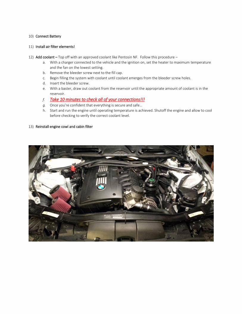
10) Connect Battery
11) Install air filter elements!
12) Add coolant – Top off with an approved coolant like Pentosin NF. Follow this procedure – a. With a charger connected to the vehicle and the ignition on, set the heater to maximum temperature
and the fan on the lowest setting. b. Remove the bleeder screw next to the fill cap. c. Begin filling the system with coolant until coolant emerges from the bleeder screw holes. d. Insert the bleeder screw. e. With a baster, draw out coolant from the reservoir until the appropriate amount of coolant is in the
reservoir.
f. Take 10 minutes to check all of your connections!!! g. Once you’re confident that everything is secure and safe… h. Start and run the engine until operating temperature is achieved. Shutoff the engine and allow to cool
before checking to verify the correct coolant level.
13) Reinstall engine cowl and cabin filter