distribution of effective stress in compaction of earth ... · ijrras 21 (3) december 2014 nohani...
TRANSCRIPT

IJRRAS 21 (3) ● December 2014 www.arpapress.com/Volumes/Vol21Issue3/IJRRAS_21_3_03.pdf
114
DISTRIBUTION OF EFFECTIVE STRESS IN COMPACTION OF EARTH
DAMS DUE TO THE THREE-SIDED IMPACT ROLLER AND
COMPARING WITH FOUR-SIDED ROLLER FIELD DATA
Ebrahim Nohani* & Heshmatolah Mirzaei 1Department of hydraulic Structures, Dezful Branch, Islamic Azad University, Dezful, Iran
* Corresponding author's Email: [email protected]
ABSTRACT
Dynamic compaction with roller is a suitable technique for compact thick layers of soil in embankment dams to
prevent and reduce infiltration, piping, water emission lines displacement and improving their performance. Impact
rollers due to their benefits are widely used in industry of improving soil engineering. They have a variety of shapes
including 3-, 4-, 5- and 8-sided. This study examines the effects of 3-sided impact roller on the distribution of effective
stress in the thick layers of the soils used in the construction of embankment dams. Finite elements method was used
for analyzing and ABAQUS software for simulation of process of compaction. Results showed that the maximum
stress occurred at impact of roller and effective stress changes in soil depth reduced and reached a constant value.
Keywords: infiltration, 3-sided impact roller, ABAQUS, effective stress
1. INTRODUCTION
The process of energy transfer to the soil by ascending-descending movement of the falling mass is called impact
compaction. Mass movement to its highest point and then its fall creates the maximum potential energy and releases
it, and energy transfer to the soil surface occurs through the fall. The amount of energy transmitted to the ground
depends on the amount of mass potential energy. One of the latest tools for impact compaction is impact roller that
has various types including 3-, 4-, 5- and 8-sided. In this study, 3-sided impact roller will be studied. The main reason
for choosing 3-sided impact roller as the subject of study in this research is its applications in various areas, some of
which are as follows:
Stopping seepage in the fields of cotton, rice and tea
Modification of infrastructure and pavement of roads and airports
Modification of problematic and collapsible soils
Compaction of thick layers of fine soil mass and landfills
Figure 1 shows the application and the picture of this roller.
Figure 1. Application of triangular impact roller in amending soil compaction

IJRRAS 21 (3) ● December 2014 Nohani & Mirzaei ● Compaction of Earth Dams
115
In the early twentieth century, the development of the dynamic compaction was performed by French engineers who
used free fall of weights. The benefits of deep dynamic compaction at the site were known since 1930s and a Swedish
engineer designed the first impact roller with hexagonal cross section in 1935 [1]. In 1990, Pinard discussed different
ways of reducing the need for water for compaction in ambient conditions in Kalahari region of South Africa. Then
they reported the results of experiments conducted to assess the appropriateness of high-energy impact roller to seek
deep compaction with low cost in a low humidity level. Tests showed that a significant reduction occurred in
compaction water needs in context of the way and hence we can achieve a great reduction in the overall cost of road
construction using high-energy impact roller that have the proper compaction energy and shape and lattice work
appropriate to the type of soil. Spengler and Hindi in 1982 noted that compaction should prevent soil dilation, hence
mean effective normal stress (P) should increase without allowing the maximum allowable shear stress (q) to exceed
the line that is characterized by Kf. This means that if the culmination of Mohr's circle is under Kf line, the behavior is
perfectly elastic. This is shown in Figure 2 [2].
Figure 2. Mohr-Coulomb lines that specify the elastic or plastic behavior [2]
In 2008, B. Scott & M. Jaksa investigated the depth of this roller on clay soils that in clay fine soils, the depth is often
observed1 to 1.5 m after 20 to 30 rollers pass [3]. So far, different approaches of the effects of impact roller have been
investigated and had good results and now, in this study, the effective stress and its changes are discussed.
2. MATERIALS AND METHODS
To stimulate the process of soil compaction with impact roller, firstly a proper modeling approach must be found to
solve the problem. Given that this kind of problems is mainly simulated to the finite element method or finite
difference method and because the possibility of convergence of responses with finite difference method in impact
and explosion is low, in this study, the finite element method is used for simulation. Finite element method is a
numerical method through which we can solve the engineering and mathematical physics problems.
The equations governing the modeling are given to consider the extent of variables changes and the effect of
simplifying on the equations by familiarity with the effective variables on the relationships.
Governing equations for the modeling roller impact on soil:
(1) 𝑀�̈� + 𝐶(𝛼, 𝛽)�̇� + 𝐾𝑢 = 𝐹(𝑡) That in this equation, M is soil mass; C the soil amortization; K soil hardness; u soil shift, �̇� soil velocity, �̈�
soil acceleration and F(t) loading exerted by the roller on the soils and variable with time.
The boundary conditions of this equation are also as follows:
α = 0.1; β = 0 that are riley attenuation coefficients.
M is obtained by multiplying the density of the soil in the soil volume.
K is obtained by integrating the matrix B so that: K = ∫BTDB
Failure envelope
q= Maximum allowable shear stress
P= Effective normal stress

IJRRAS 21 (3) ● December 2014 Nohani & Mirzaei ● Compaction of Earth Dams
116
That in this equation, matrix B is obtained by the derivative of the function of N shape. Note that ABAQUS used
linear function in the analyses.
Matrix D in this equation is also achieved by soil profile determined with Young's modulus and Poisson's ratio and
soil plasticity.
F (t) is achieved by the product of the roller mass m in the roller free fall acceleration i.e. a (t).
For the simulation of the process of soil compaction with 3-sided impact roller, first an appropriate modeling method
should be found to solve the problem. Given that, these kinds of problems are mainly simulated by finite element or
finite difference methods and because the probability of responses convergence in finite difference method on issues
of impact and explosion is low, the finite element method is used for simulation in this investigation.
In this research ABAQUS/STANDARD is used to study the changes in the pore pressure distribution in the soil under
compression. ABAQUS/Explicit is also used for modeling the three-and four-sided rollers and soil density with it and
determination of the amount of load equivalent to roller to use in pore pressure distribution changes analysis.
Soil field data is derived from the laboratory research of Mantha et al., in the University of Adelaide, Australia in 2011
[4]. The profile of roller used for the compaction of soil in the field is also selected identical. Therefore, roller BH-
1300 which is 8 tons and made in Broons Australia was modeled.
Fieldwork conducted by Mantha et al., in 2011 is in project on improvement of magnetic tailings dam soil at the Iron
Duke Mine in South Australia. The results of sieve analysis and plasticity tests determined that soil is the fine
aggregated sand with small amounts of sand-sized material (14%) and clay particles (6%) with low plasticity (LL = ~
22%, PL = ~ 11%). Average moisture content was 5% and groundwater level was sufficiently less than the effect of
compaction with roller. Test plates were placed in three directions in which the falling height was measured 1200 mm.
Earth pressure cells (EPC) measurement were placed at the various vertical and lateral surfaces. These cells were
connected to a laptop and a data acquisition system to continuously measure and record the pressure induced by the
impact roller. Cells data for roller both at rest and in motion was analyzed and reported. Direct and Triaxial shear tests
were done by Kuo et al to complete the engineering properties of soil that the results of key soil parameters are given
in Table 1 quoted by his research. Poisson's ratio is also assumed 0.3 for analyses.
Table 1. The most key soil parameters quoted by Kuo et al (2013) [5]
Their empirical results showed the surface seepage 5.1 mm after the roller impact on the soil. Also, the results of Jaksa
et al research in 2009 demonstrated that the time of roller impact on the soil, 137 Kn will be imposed on the manometer
cell tangent to the surface of the land, that is, this amount of force can be used as the equivalent to the roller loading
1.0 seconds. The numerical modeling and the verification will be followed.
All the stages of the simulation are done in ABAQUS through modules given in the following. According to recent
researches, to model the general behavior of rollers, shell element was used to model the roller. Solid element was
used for modeling soil. Discrete technique of surface was used for soil lateral surfaces to prepare the soil for
loading. To reduce the effect of impact wave return to the environment and disrupting responses, the soil length was
considered 25 m and its depth 20 meters to provide the stress bulb due to roller impact to at least twice the width of
roller with a confidence coefficient. In this study, the model consists of two general elements: roller element and soil
element. By moving the impact rollers on the soil, the impact compaction process is formed. Explicit dynamic analysis
was used for this model. Considering the effect of large geometrical changes was enabled in the software to increase
responses accuracy. It applied the centralized anchor 200 kN to the roller. To apply boundary conditions to the soil,
all degrees of freedom of the underlying surface of the soil was clamped. Contact behavior between the soil and roller
was considered by the tangent behavior in which it applied with the friction factor μ = 0.3. Due to continuity of
environment of the continuous elements and based on the three dimensional model of the three-dimensional stress
elements; 8-node element with reduced integral C3D8R for the soil elements was used in the dynamic analysis. For
meshing the roller in both analyses, CPS3 element was used which is a linear triangular element and it is an element
from the three nodes family.

IJRRAS 21 (3) ● December 2014 Nohani & Mirzaei ● Compaction of Earth Dams
117
According to the experimental data obtained by a four-sided roller, we simulated a 4-sided model which is given
following the results.
3. VERIFICATION
As shown in Fig 3 and 4, the amount of surface settlement 4.5 mm obtained from the four-sided roller impact to the
soil in case of two dimensions only 6.0 mm varies from the field results of (5.1 mm of Kuo et al. research [5] ), and
shows a good agreement.
Now that the four-sided roller was verified with field results, the roller shape can be changed into three-sided and a
parametric study can be done on model variables. Finally, the effective stress and pore water pressure will be obtained.
After modeling the three-sided roller, stress distribution in the soil and pore pressure distribution will also be obtained
and then the results will be entered to an excel file and effective stress distribution (total stress minus the pore
pressure) under the three-sided roller impact will be obtained.
Figure 3. The settlement distribution in soil to verify the numerical model with field results

IJRRAS 21 (3) ● December 2014 Nohani & Mirzaei ● Compaction of Earth Dams
118
Shape 4. The variation of settlement in soil depth resulting from the numerical model
4. RESULTS AND DISCUSSION
As shown in Figure 5, the pore pressure distribution in the region of roller effect has many variations, and these
variations are reduced in soil depth and reach a relatively constant value. Diagram of the variation of the pore pressure
in the soil is shown in Figure 6.
Figure 5. pore pressure distribution in the soil depth resulting from the numerical model

IJRRAS 21 (3) ● December 2014 Nohani & Mirzaei ● Compaction of Earth Dams
119
Figure 6. The variations of pore pressure in depth of the soil
As shown in Figure 7, the highest stress is at the impact of this roller and the stress is reduced in the depth of
the soil. Diagram of stress changes in soil is given in Figure 8.
Figure 7. The distribution of general stresses in the soil
Finally, from the difference between the numbers relating to the total stress and pore pressure which graphs are inserted
in Figures 6 and 8, the graph of the variations of the effective stress in the soil depth resulting from compaction by
roller will be obtained which is given in Figure 9. As can be seen in this figure, the variation of the effective stress in
the soil from compaction by roller is decreased by increasing the depth and reaches a constant value.

IJRRAS 21 (3) ● December 2014 Nohani & Mirzaei ● Compaction of Earth Dams
120
Figure 8. The variation of stress in the soil depth
Shape 9. The variation of the effective stress in the soil depth
Improved estimation of the depth of soil as a result of compaction with roller is one of the best ways to determine the
effect depth in soil, estimating the depth from the graph of stress changes with depth and shape of the stress distribution
in the soil. As can be seen in figures 7 and 8, the roller stress bulb has the most effect to a depth of 2.5 meters (stress
contour of yellow zone in Figure 7). Results of research by Kuo et al in 2013 has also introduced the depth
of 2.35 meters as improved depth with these rollers which is very similar to the present numerical model.
Increasing the soil moisture content from 0.25 to 0.4 caused a 35% reduction in the improved depth and increasing
the soil moisture content from 0.4 to 0.6 causes a 0.28 reduction in the improved depth. This result shows that with
further increase of soil moisture content, the descending variation of the improved depth will be reduced and tend to
a constant value.
As can be seen, because in the impact roller system, increasing the soil moisture leads to decreasing the efficiency of
the roller, compared with the vibratory roller that always need increasing soil moisture for the roller efficiency, it can

IJRRAS 21 (3) ● December 2014 Nohani & Mirzaei ● Compaction of Earth Dams
121
be concluded that when using impact rollers, we need less water consumption in comparison to the vibratory roller
which results in decreasing the pore water pressure and increasing the effective stress of the soil.
4.1. COMPARISON OF THE EFFECTIVE STRESS CHANGES WITH SOIL DEPTH IN THREE- AND
FOUR-SIDED ROLLERS:
As shown in Fig. 10, the peak of the effective stress applied to the soil from the three-sided roller is more than four
sided while total stress peak of the four-sided roller is more than three-sided roller. Hence due to the role of pore
pressure, the use of three-sided rollers is recommended for deep densities and four-sided rollers for surface densities.
Figure 10. comparison of effective stress variation with depth
4.2. A PARAMETRIC COMPARISON OF THREE- AND FOUR-SIDED ROLLERS BEHAVIORS:
As shown in Figure 11, the maximum soil strain under 4-sided roller is 0.036 and maximum strain of the soil under
3-sided roller is 0.044. So, 22% increase in the strains of the soil under 3-sided roller than 4-sided can be seen.
Figure 11. comparison of strain variation with depth
As shown in Figure 12, the maximum pore pressure in soil under 4-sided roller is 8.5 MPa and maximum pore
pressure in soil under 3-sided roller is 8.97 MPA. Therefore, a 5.5% increase in the pore pressure of soil under the
effect of 3-sided roller than 4-sided can be seen.
-1.50E+07
-1.00E+07
-5.00E+06
0.00E+00
5.00E+06
1.00E+07
1.50E+07
2.00E+07
0 5 10 15 20 25
3 Sided Roller
4 sided roller

IJRRAS 21 (3) ● December 2014 Nohani & Mirzaei ● Compaction of Earth Dams
122
Figure 12. comparison of pore pressure variation with depth
As shown in Figure 13, the maximum stress in the soil under the 4-sided roller is 8.34 MPa and maximum stress in
soil under 3-sided roller is 8.90 MPA. Therefore, a 6.7% increase in stress in the soil under the effect of 3-sided roller
than 4-sided can be seen.
Figure 13. comparison of stress variation with depth
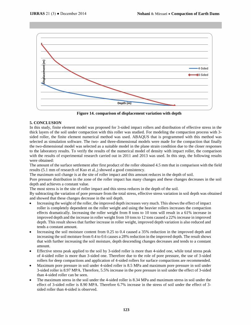
As shown in Figure 14, the maximum displacement of soil under the effect of 4-sided roller is 4.5 mm and the
maximum displacement of soil under the effect of 3-sided roller is 1.7 mm. Therefore, 2.65 times increase in the
maximum displacement of soil under the effect of 3-sided than 4-sided roller can be seen.
Stre
ss (
MP
a)
Depth (m)
4-Sided
3-Sided
IJRRAS 21 (3) ● December 2014 Nohani & Mirzaei ● Compaction of Earth Dams
123
Figure 14. comparison of displacement variation with depth
5. CONCLUSION
In this study, finite element model was proposed for 3-sided impact rollers and distribution of effective stress in the
thick layers of the soil under compaction with this roller was studied. For modeling the compaction process with 3-
sided roller, the finite element numerical method was used. ABAQUS that is programmed with this method was
selected as simulation software. The two- and three-dimensional models were made for the compaction that finally
the two-dimensional model was selected as a suitable model in the plane strain condition due to the closer responses
to the laboratory results. To verify the results of the numerical model of density with impact roller, the comparison
with the results of experimental research carried out in 2011 and 2013 was used. In this step, the following results
were obtained:
The amount of the surface settlement after first product of the roller obtained 4.5 mm that in comparison with the field
results (5.1 mm of research of Kuo et al.,) showed a good consistency.
The maximum soil change is at the site of roller impact and this amount reduces in the depth of soil.
Pore pressure distribution in the zone of the roller impact has many changes and these changes decreases in the soil
depth and achieves a constant value.
The most stress is in the site of roller impact and this stress reduces in the depth of the soil.
By subtracting the variation of pore pressure from the total stress, effective stress variation in soil depth was obtained
and showed that these changes decrease in the soil depth.
Increasing the weight of the roller, the improved depth increases very much. This shows the effect of impact
roller is completely dependent on the roller weight and using the heavier rollers increases the compaction
effects dramatically. Increasing the roller weight from 8 tons to 10 tons will result in a 61% increase in
improved depth and the increase in roller weight from 10 tons to 12 tons caused a 22% increase in improved
depth. This result shows that further increase in roller weight, improved depth variation is also reduced and
tends a constant amount.
Increasing the soil moisture content from 0.25 to 0.4 caused a 35% reduction in the improved depth and
increasing the soil moisture from 0.4 to 0.6 causes a 28% reduction in the improved depth. The result shows
that with further increasing the soil moisture, depth descending changes decreases and tends to a constant
amount.
Effective stress peak applied to the soil by 3-sided roller is more than 4-sided one, while total stress peak
of 4-sided roller is more than 3-sided one. Therefore due to the role of pore pressure, the use of 3-sided
rollers for deep compactions and application of 4-sided rollers for surface compactions are recommended.
Maximum pore pressure in soil under 4-sided roller is 8.5 MPa and maximum pore pressure in soil under
3-sided roller is 8.97 MPA. Therefore, 5.5% increase in the pore pressure in soil under the effect of 3-sided
than 4-sided roller can be seen.
The maximum stress in the soil under the 4-sided roller is 8.34 MPa and maximum stress in soil under the
effect of 3-sided roller is 8.90 MPA. Therefore 6.7% increase in the stress of soil under the effect of 3-
sided roller than 4-sided is observed.
Dis
pla
cem
en
t (m
)
Depth (m)
4-Sided
3-Sided

IJRRAS 21 (3) ● December 2014 Nohani & Mirzaei ● Compaction of Earth Dams
124
6. REFERENCES
[1] N. A.Nategh, A. Hemmat., M. Sadeghi and M. Vafaian, 1387, The effect of some factors affecting the resistance
to compression (tension-compression) of a silty clay loam soil., 5th National Congress of Agricultural Machinery
Engineering and Mechanization, Mashhad, Engineering Society Agricultural Machinery and Mechanization of
Iran, Ferdowsi University of Mashhad.
[2] Avalle, D.L. and Carter J.P. (2005). “Evaluating the improvement from impact rolling on sand.” Proc. 6th Int.
Conf. on Ground Improvement Techniques, Portugal.
[3] Avalle, D.L. and McKenzie, R.W. (2005). “Ground improvement of landfill site using the square impact roller.”
Australian Geomechanics, Vol. 40, No. 4, pp. 15-21.
[4] Mentha N., Pointon S., Symons A. and Wrightson P. 2011. The Effectiveness of the Impact Roller. Adelaide,
Australia: B.Eng.(Hons), The University of Adelaide.
[5] Kuo Y.L., Jaksa M.B., Scott B.T., Bradley A.C., Power C.N., Crisp A.C., Jiang J.H.,2013. Assessing the
Effectiveness of Rolling Dynamic Compaction, Proceedings of the 18th International Conference on Soil
Mechanics and Geotechnical Engineering, Paris.