distributed i/o simatic et 200 - paratrasnet o...distributed i/o simatic et 200 et 200s — i/o...
TRANSCRIPT

Siemens IK PI News · January 2010
5/2 ET 200S5/2 I/O modules
5/2 Power modules for PM-E electronic modules
5/4 Digital electronic modules
5/6 IO-Link master modules
5/6 4SI IO-Link electronic module
5/6 4SI SIRIUS electronic module
5/7 Software
5/7 Motor Starter ES
5/10 ET 200pro5/10 IM 154-6 PN IWLAN
5/13 SIMATIC ET 200pro PS
Sec. 2 SIMATIC RF180C/RF182C
5/16 ET 200eco PN5/16 ET 200eco PN
Distributed I/O SIMATIC ET 200
Kap_05_Titel_en.fm Seite 1 Freitag, 29. Januar 2010 10:13 10
© Siemens AG 2010

Distributed I/O SIMATIC ET 200ET 200S — I/O modules
Power modules for PM-E electronic modules
5/2 Siemens IK PI News · January 2010
5
n Overview
• For monitoring and, depending on the version, fusing the load and sensor supply voltage
• Can be plugged onto TM-P terminal modules with automatic coding.
• Diagnostics message for voltage and blown fuse (can be switched off via configuration)
• PM-E 24 V DC Standard - Load voltage diagnostics
• PM-E 24 V DC High Feature - Load voltage and reverse voltage diagnostics- With status information - Option handling (only in combination with the IM 151-1 Stan-
dard, IM 151-1 FO Standard and IM 151-1 High Feature)
• 24 to 48 V DC PM-E power module - Load voltage diagnostics- With status information- Option handling (only in combination with the IM 151-1 Stan-
dard, IM 151-1 FO Standard and IM 151-1 High Feature)
• PM-E 24 V DC to 230 V AC power module - power module for universal use- with integral replaceable fuse- With status information- Option handling (only in combination with the IM 151-1 Stan-
dard, IM 151-1 FO Standard and IM 151-1 High Feature)
n DesignPM-E power modules are plugged into the TM-P terminal modules provided for the purpose.
The first module after the IM 151-3 must be a power module.
The version for fusing has a fusible link (5 x 20 mm). Up to 6 replacement fuses can be stored in the terminating module (see IM 151).
Possible combinations of the TM-E terminal modules and power modules
Possible combinations of the electronics modules and power modules
Power modules TM-P terminal modules for power modulesScrew-type terminal 15S23-A1 15S23-A0 15S22-01 30S44-A0 F30S47-F0Order No. 6ES7 193… …4CC20-0AA0 …4CD20-0AA0 …4CE00-0AA0 …4CK20-0AA0 3RK1903-3AA0
Spring-loaded terminal 15C23-A1 15C23-A0 15C22-01 30C44-A0 –Order No. 6ES7 193… …4CC30-0AA0 …4CD30-0AA0 …4CE10-0AA0 …4CK30-0AA0 –
FastConnect 15N23-A1 15N23-A0 15N22-01 – –
Order No. 6ES7 193… …4CC70-0AA0 …4CD70-0AA0 …4CE60-0AA0 – –
PM-E 24 V DC ST n n n
PM-E 24 V DC HF n n n
PM-E 24 to 48 V DC n n n
PM-E 24 ... 48 V DC/24 ... 230 V AC n n n
Power modules Electronic modulesPM-E 24 V DC ST Can be used for all electronics
modules except 2 DI 120 V AC ST, 2 DI 230 V AC ST and 2 DO 120/230 V AC
PM-E 24 V DC HF Can be used for all electronics modules except 2 DI 120 V AC ST, 2 DI 230 V AC ST and 2 DO 120/230 V AC
PM-E 24 to 48 V DC Can be used for all 15 mm-wide electronics modules except 2 DI 120 V AC ST, 2 DI 230 V AC ST and 2 DO 120/230 V AC as well as for 4 DI 24 to 48 V UC in AC operation
PM-E 24 ... 48 V DC/24 ... 230 V AC Can be used with all 15 mm-wide electronic modules
N
Kap_05_en.fm Seite 2 Freitag, 29. Januar 2010 10:12 10
© Siemens AG 2010

Distributed I/O SIMATIC ET 200ET 200S — I/O modules
Power modules for PM-E electronic modules
5/3Siemens IK PI News · January 2010
5
n Ordering data Order No. Order No.
1) Can be used for all electronic and technology modules except 2 DI 120 V AC / 2 DI 230 V AC / 2 DO 120/230 V AC
Selection tool for terminal modules
PM-E 24 V DC Standard power module 1) 6ES7 138-4CA01-0AA0
For electronic modules; with diagnostics
PM-E 24 V DC High Feature power module 1) 6ES7 138-4CA60-0AB0
For electronic modules; with diagnostics
24 … 48 V DC PM-E power module
6ES7 138-4CA50-0AB0
For electronic modules; with diagnostics, with status bit "load voltage" present
Power module PM-E 24 … 48 V DC, 42 … 230 V AC
6ES7 138-4CB11-0AB0
For electronic modules; with diagnostics and fuse
N
AccessoriesLabel sheets DIN A4 (10 pieces)Each sheet contains 60 label strips for peripheral modules and 20 label strips for interface modules
• petrol 6ES7 193-4BH00-0AA0• red 6ES7 193-4BD00-0AA0• yellow 6ES7 193-4BB00-0AA0• light beige 6ES7 193-4BA00-0AA0
Power modules TM-P terminal modules for power modulesScrew-type terminal type designation
TM-P15S23-A1 TM-P15S23-A0 TM-P15S22-01 TM-P30S44-A0
Order No. 6ES7 193... 4CC20-0AA0 4CD20-0AA0 4CE00-0AA0 4CK20-0AA0
Spring-loaded terminaltype designation
TM-P15C23-A1 TM-P15C23-A0 TM-P15C22-01 TM-P30C44-A0
Order No. 6ES7 193... 4CC30-0AA0 4CD30-0AA0 4CE10-0AA0 4CK30-0AA0
FastConnect type designation TM-P15N23-A1 TM-P15N23-A0 TM-P15N22-01 Soon to comeOrder No. 6ES7 193... 4CC70-0AA0 4CD70-0AA0 4CE60-0AA0
PM-E 24 V DC n n n
PM-E 24 … 48 V DC n n n
PM-E 24 V DC/120/230 V AC n n n
PM-E F 24 V DC PROFIsafe n
Kap_05_en.fm Seite 3 Freitag, 29. Januar 2010 10:12 10
© Siemens AG 2010

Distributed I/O SIMATIC ET 200ET 200S — I/O modules
Digital electronic modules
5/4 Siemens IK PI News · January 2010
5
n Overview • 2, 4 and 8-channel digital inputs and outputs for the ET 200S
• Can be plugged onto TM-E terminal modules with automatic coding.
• High-feature versions for enhanced plant availability, addi-tional functions and comprehensive diagnostics
• Hot swapping of modules possible
n DesignDifferent potentials are available on the terminals depending on the selected terminal module.
Possible combinations of the TM-E terminal modules and digital modules
Electronic modules TM-E terminal modules for electronics modulesScrew-type terminal 15S26-A1 15S24-A1 15S24-01 15S23-01 15S24-AT 30S44-01 30S46-A1Order No. 6ES7 193… …4CA40-0AA0 …4CA20-0AA0 …4CB20-0AA0 …4CB00-0AA0 …4CL20-0AA0 …4CG20-0AA0 …4CF40-0AA0
Spring-loaded terminal 15C26-A1 15C24-A1 15C24-01 15C23-01 15C24-AT 30C44-01 30C46-A1Order No. 6ES7 193… …4CA50-0AA0 …4CA30-0AA0 …4CB30-0AA0 …4CB10-0AA0 …4CL30-0AA0 …4CG30-0AA0 …4CF50-0AA0
FastConnect 15N26-A1 15N24-A1 15N24-01 15N23-01 – – –
Order No. 6ES7 193… …4CA80-0AA0 …4CA70-0AA0 …4CB70-0AA0 …4CB60-0AA0
2DI 24 V DC ST
2DI 24 V DC HF
4DI 24 V DC ST
4DI 24 V DC HF
4DI 24 V DC /SRC ST
n n n n
4DI 24 … 48 V UC HF n n n n
4 DI NAMUR n n n n
8 DI 24 V DC, ST
8 DI, 24 VDC ST source input
n n n
2 DI 120 V AC ST n n n n
2 DI 230 V AC ST n n n n
2 DO 24 V DC/0.5 A ST
2 DO 24 V DC/0.5 A HF
4 DO 24 V DC/0.5 A ST
4 DO, 24 VDC / 0.5 A ST sink output
4 DO 24 V DC/0.5 A HF
n n n n
8 DO 24 V DC/0.5 A ST
8 DO, 24 VDC / 0.5 A ST sink output
8 DO 24 V DC/0.5 A HF
n n
2 DO 24 V DC/2 A ST
2 DO 24 V DC/2 A HF
4 DO 24 V DC/2 A ST
4 DO 24 V DC/2 A HF
n n n n
2 DO 24 … 230 V AC/2 A n n n n
2RO NO24 … 120 V DC/5 A, 24 … 230 V AC/5 A
2RO NO/NC24 … 48 V DC/5 A, 24 … 230 V AC/5 A
2RO NO/NC24 … 48 V DC/5 A, 24 … 230 V AC/5 A, with manual operation
n n n n
N
N
N
N
Kap_05_en.fm Seite 4 Freitag, 29. Januar 2010 10:12 10
© Siemens AG 2010

Distributed I/O SIMATIC ET 200ET 200S — I/O modules
Digital electronic modules
5/5Siemens IK PI News · January 2010
5
n Ordering data Order No. Order No.
Digital input modulesOrdering unit 5 items
• 2 DI 24 V DC Standard 6ES7 131-4BB01-0AA0• 2 DI 24 V DC High Feature 6ES7 131-4BB01-0AB0• 4 DI 24 V DC Standard 6ES7 131-4BD01-0AA0• 4 DI 24 V DC High Feature 6ES7 131-4BD01-0AB0• 2 DI 120 V AC 6ES7 131-4EB00-0AB0• 2 DI 230 V AC 6ES7 131-4FB00-0AB0• 4 DI 24 … 48 V UC 6ES7 131-4CD00-0AB0• 4 DI 24 V DC SOURCE INPUT 6ES7 131-4BD51-0AA0Ordering unit 1 item
• 4 DI 24 V DC NAMUR 6ES7 131-4RD00-0AB0• 8 DI 24 V DC Standard 6ES7 131-4BF00-0AA0• 8 DI, 24 VDC, standard
SOURCE INPUT6ES7 131-4BF50-0AA0
Digital output modulesOrdering unit 5 items
• 2 DO 24 V DC/0.5 A Standard 6ES7 132-4BB01-0AA0• 2 DO 24 V DC/0.5 A
High Feature6ES7 132-4BB01-0AB0
• 2 DO 24 V DC/2 A Standard 6ES7 132-4BB31-0AA0• 2 DO 24 V DC/2 A High Feature 6ES7 132-4BB31-0AB0• 4 DO 24 V DC/0.5 A Standard 6ES7 132-4BD02-0AA0• 4 DO, 24 VDC / 0.5 A, standard
SOURCE OUTPUT6ES7 132-4BD50-0AA0
• 4 DO 24 V DC/0.5 A High Feature
6ES7 132-4BD00-0AB0
• 8 DO 24 V DC/0.5 A High Feature
6ES7 132-4BF00-0AB0
• 4 DO 24 V DC/2 A Standard 6ES7 132-4BD32-0AA0• 4 DO 24 V DC/2 A High Feature 6ES7 132-4BD30-0AB0 • 2 DO 24 … 230 V AC/2 A 6ES7 132-4FB01-0AB0• 2 DO 24 V DC … 230 V AC/5 A
relay, NO contact6ES7 132-4HB01-0AB0
• 2 DO 24 ... 48 V DC/5 A,24 ... 230 V AC/5 A relay, changeover contact
6ES7 132-4HB10-0AB0
Ordering unit 1 item
• 2 DO 24 ... 48 V DC/5 A, 24 ... 230 V AC/5 A relay, changeover contact, with manual operation
6ES7 132-4HB50-0AB0
• 8 DO 24 V DC/0.5 A Standard 6ES7 132-4BF00-0AA0• 8 DO, 24 VDC / 0.5 A, standard
SOURCE OUTPUT6ES7 132-4BF50-0AA0
N
N
N
N
AccessoriesLabel sheets DIN A4 (10 pieces)Each sheet contains 60 label strips for peripheral modules and 20 label strips for interface modules
• petrol 6ES7 193-4BH00-0AA0• red 6ES7 193-4BD00-0AA0• yellow 6ES7 193-4BB00-0AA0• light beige 6ES7 193-4BA00-0AA0
Kap_05_en.fm Seite 5 Freitag, 29. Januar 2010 10:12 10
© Siemens AG 2010

Distributed I/O SIMATIC ET 200ET 200S — IO-Link master modules4SI IO-Link electronic module4SI SIRIUS electronic module
5/6 Siemens IK PI News · January 2010
5
n Overview
The 4SI IO-Link electronic module is an IO-Link master and supports the easy integration of sensors and actuators from different manufacturers in the multifunctional, distributed I/O system SIMATIC ET 200S on a total of four ports.
Features
• Up to 4 IO-Link devices can be connected to each IO-Link master module (3-wire connection)
• Up to 4 standard actuators or sensors (2-wire/3-wire connec-tion) can be connected.
• The electronic module 4SI IO-Link is 15 mm in width and can be used with the following universal terminal modules: - TM-E15S26-A1 (screw-type terminal)- TM-E15C26-A1 (spring-loaded terminal)- TM-E15N26-A1 (FastConnect)
• Supports firmware update (STEP 7 V5.4 SP4 and higher)
n Ordering data Order No.
n More informationFurther information and technical data can be found in the Industry M under: "Automation technology" --> "Industrial Communication" --> "IO-Link" --> "Master"--> IO-Link master module for ET 200S
n Overview
The 4SI SIRIUS electronic module supports easy, cost-effective connection of SIRIUS switching devices with IO-Link to the multifunctional, distributed I/O system SIMATIC ET 200S on a total of four ports.
Features
• Up to 4 SIRIUS switching devices (max. 16 for groups of four) can be connected to each IO-Link SIRIUS module usingIO-Link (3-wire connection)
• The electronic module 4SI SIRIUS is 15 mm in width and can be used with the following universal terminal modules: - TM-E15S26-A1 (screw-type terminal) - TM-E15C26-A1 (spring-loaded terminal) - TM-E15N26-A1 (FastConnect)
• Supports firmware update (STEP 7 V5.4 SP5 and higher).
n Ordering data Order No.
n More informationFurther information and technical data can be found in the Industry M under: "Automation technology" --> "Industrial Communication" --> "IO-Link" --> "Master"--> IO-Link master module SIRIUS for ET 200S
Electronic module 4SI IO-Link 6ES7 138-4GA50-0AB0IO-Link master
Connection method:
Screw terminal, spring-loaded terminal or FastConnect
4SI SIRIUS electronic module 3RK1 005-0LB00-0AA0IO-Link master
Connection method:
Screw-type terminal,spring-loaded terminal or FastConnect
Kap_05_en.fm Seite 6 Freitag, 29. Januar 2010 10:12 10
© Siemens AG 2010

Distributed I/O SIMATIC ET 200ET 200S — Software
Motor Starter ES
5/7Siemens IK PI News · January 2010
5
n Overview
Motor Starter ES for parameterization, monitoring, diagnostics and testing of motor starters
Motor Starter ES 2007Motor Starter ES is used for start-up, parameterization, diagnos-tics, documentation and the preventative maintenance of the motor starters in the SIMATIC ET 200S, ET 200pro, ECOFAST and M200D product families .
Interfacing is performed
• Through the local interface on the device
• With PROFIBUS DP V1-capable motor starters from any point in PROFIBUS or in PROFINET (applies for ET 200pro/ECOFAST/M200D)
• With PROFINET-capable motor starters from any point in PROFINET or PROFIBUS (applies for M200D).
Using Motor Starter ES, the communication-capable motor start-ers are easily parameterized during start-up, monitored during normal operation and successfully diagnosed for service pur-poses. Preventative maintenance is supported by a function for reading out diverse statistical data (e.g. operating hours, oper-ating cycles, cut-off currents, etc.). The user is supported during these procedures with comprehensive Help functions and plain text displays.
The advantages of Motor Starter ES:
• Clearly arranged configuring of device functions and their parameters – online and offline
• Effective diagnostics functions on the soft starter and display of the most important measured values
• Trace function (oscilloscope function) for recording measured values and events (included in the Motor Starter ES Standard and Premium software version for M200D PROFIBUS and PROFINET).
Motor Starter ES can either be used as a stand-alone program or it can be integrated into STEP 7 via an object manager.
Efficient engineering with new program versionsThe Motor Starter ES software program is available in three versions which differ in their user-friendliness, scope of functions and price.
3 Function available -- Function not available1) Typicals with Service Pack 1 and higher.2) Trace function and access through PROFINET Service Pack 2 and higher.
3 Function available -- Function not available1) With Service Pack 2 and higher.2) Trace function is not supported.
N
Motor Starter ES Basic Standard PremiumAccess through the local interface on the device
4 4 4
Parameter assignment 4 4 4
Operating 4 4 4
Diagnostics -- 4 4
Creating typicals -- 41)
41)
Comparison functions -- 4 4
Standards-conform printout according to EN ISO 7200
-- 4 4
Service data (slave pointer, statistics data)
-- 4 4
Access through PROFIBUS -- -- 4
Access through PROFINET -- -- 42)
S7 Routing -- -- 4
Teleservice through MPI -- -- 4
STEP 7 object manager -- -- 4
Trace function -- 42)
42)
Motor Starter ES Basic Standard PremiumET 200S High Feature PROFIBUS IM
4 4 --
ET 200S High Feature PROFINET IM
4 4 --
ECOFAST AS-Interface High Feature
4 4 --
ECOFAST PROFIBUS 4 4 4
ET 200pro PROFIBUS IM 4 4 4
ET 200pro PROFINET IM 4 4 4
M200D AS-Interface Standard 41)
41)2) --
M200D PROFIBUS 41)
41)
41)
M200D PROFINET 41)
41)
41)
N
N
Kap_05_en.fm Seite 7 Freitag, 29. Januar 2010 10:12 10
© Siemens AG 2010

Distributed I/O SIMATIC ET 200ET 200S — Software
Motor Starter ES
5/8 Siemens IK PI News · January 2010
5
n Overview (continued)
More functions• Standards-conform printouts
The software tool greatly simplifies machine documentation.It enables parameterization printouts according to EN ISO 7200. The elements to be printed are easy to select and group as required.
• Easy creation of typicalsTypicals can be created for devices and applications with only minimum differences in their parameters. These typicals contain all the parameters which are needed for the parame-terization. In addition, it is possible to specify which of these parameters are fixed and which can be adapted, e.g. by the startup engineer.
• Teleservice through MPIThe Motor Starter ES Premium version supports the use of MPI Teleservice (comprising the Teleservice software and various Teleservice adapters) for remote diagnostics of the devices. This facilitates diagnostics and maintenance, and it shortens response times for service purposes.
Types of delivery and licenseMotor Starter ES is available as follows:
• Floating license – the license for any one user at any one time- Authorizes any one user- Independent of the number of installations (unlike the single
license which is allowed to be installed once only)- Only the actual use of the program has to be licensed- Trial license (free use of all program functions for 14 days for
test and evaluation purposes, included on every product CD, available in the download file of the SIRIUS ES program in the Service&Support portal).
Following delivery versions are also available for Motor Starter ES 2007:
• UpgradeSwitching from an old to a new version with expanded func-tions, e.g. upgrade from Motor Starter ES 2006 to Motor Starter ES 2007.
• PowerpackSpecial pack for switching within the same software version to a more powerful version with more functionality, e.g. Power-pack Motor Starter ES 2007 for switching from Standard to Premium.
• Software Update ServiceTo keep you up to date at all times, we offer a special service which supplies you automatically with all service packs and upgrades.
• License DownloadUser-friendly license key download from our Mall (currently only for customers from Germany) as an easy and quick way for you to receive additional licenses for your software.
System requirements
1) Windows XP Professional Service Pack 3 with Motor Starter ES 2007 + SP2 and higher.
2) Windows Vista Ultimate 32/Business 32 with Motor Starter ES 2007 + SP1 and higher.
3) Windows Vista Ultimate 32/Business 32 Service Pack 1 with Motor Starter ES 2007 + SP2 and higher.
4) Allow for additional free space, e.g. for swap-out files.
Parameterization, start-up and diagnostics software Motor Starter ES 2007For ECOFAST Motor Starter, SIMATIC ET 200S High-Feature Starter, SIMATIC ET 200pro Starter and M200D (AS-I Standard, PROFIBUS, PROFINET)
Operating system Windows XP Professional (Service Pack 2, Service Pack 31)), Windows Vista Ultimate 32/Business 322) (Service Pack 13))
Processor ≥ Pentium 800 MHz/≥ 1 GHz (Windows Vista)
RAM ≥ 512 MB/≥ 1 GB (Windows Vista)
Monitor resolution ≥ 1024 x 768
Free space on hard disk4)≥ 400 MB
CD-ROM/DVD drive Yes (only when installing from CD)
Serial interface (COM) Yes
PC cable/parameterization cable/connection cable Yes
PROFIBUS card/PROFIBUS processor Optional, for parameterization and diagnostics through PROFIBUS
Ethernet interface/PROFINET card Optional, for parameterization and diagnostics through PROFINET
Kap_05_en.fm Seite 8 Freitag, 29. Januar 2010 10:12 10
© Siemens AG 2010

Distributed I/O SIMATIC ET 200ET 200S — Software
Motor Starter ES
5/9Siemens IK PI News · January 2010
5
n Ordering data Order No. Order No.Parameterization, start-up and diagnostics software Motor Starter ES 2007For ECOFAST Motor Starter, SIMATIC ET 200S High-Feature Starter, SIMATIC ET 200pro Starter and M200D (AS-I Standard, PROFIBUS, PROFINET)
• Can be run under WIN XP PROF/Windows Vista Ultimate 32/Business 32
• Without PC cable
Motor Starter ES 2007 BasicFloating license for one userE-SW, software and documenta-tion on CD, 3 languages (Ger-man/English/French), communication through system interface
• License key on USB stick, Class A, including CD
3ZS1 310-4CC10-0YA5• License key download,
Class A, no CD3ZS1 310-4CE10-0YB5
Motor Starter ES 2007 StandardFloating license for one userE-SW, software and documentation on CD, 3 languages (German/English/French), communication through system interface
• License key on USB stick, Class A, including CD
3ZS1 310-5CC10-0YA5
• License key download, Class A, no CD
3ZS1 310-5CE10-0YB5
Upgrade for Motor Starter ES 2006Floating license for one user,E-SW, software and documentation on CD, license key on USB stick, Class A, 3 languages (German/English/French), communication through the system interface
3ZS1 310-5CC10-0YE5
Powerpack for Motor Starter ES 2007 BasicFloating license for one user,E-SW, software and documentation on CD, license key on USB stick, Class A, 3 languages (German/English/French), communication through the system interface
3ZS1 310-5CC10-0YD5
Software Update Service For 1 year with automatic extension, assuming the current software version is in use, E-SW, software and documentation on CD, communication through the system interface
3ZS1 310-5CC10-0YL5
Motor Starter ES 2007 PremiumFloating license for one userE-SW, software and documentation on CD, 3 languages (German/English/French), communication through system interface or PROFIBUS
• License key on USB stick, Class A, including CD
3ZS1 310-6CC10-0YA5• License key download,
Class A, no CD3ZS1 310-6CE10-0YB5
Upgrade for Motor Starter ES 2006Floating license for one user,E-SW, software and documentation on CD, license key on USB stick, Class A, 3 languages (German/English/French), communication through the system interface or PROFIBUS
3ZS1 310-6CC10-0YE5
Powerpack for Motor Starter ES 2007 StandardFloating license for one user,E-SW, software and documentation on CD, license key on USB stick, Class A, 3 languages (German/English/French), communication through the system interface or PROFIBUS
3ZS1 310-6CC10-0YD5
Software Update Service For 1 year with automatic extension, assuming the current software version is in use, E-SW, software and documentation on CD, communication through the system interface or PROFIBUS
3ZS1 310-6CC10-0YL5
AccessoriesFor ET 200S High Feature motor starters• Control module 2DI DC 24 V COM,
for ET 200S High-Feature starter, Failsafe Starter A
3RK1 903-0CH10
• LOGO! PC cables 6ED1 057-1AA00-0BA0For ET 200pro motor startersRS232 interface cable, serial data connection between ET 200pro MS/FC and laptop/PC/PG or MS
3RK1 922-2BP00
For ECOFAST High Feature motor starters (interface cable)• PC cables 3RK1 911-0BN20USB/serial adaptersTo connect a serial PC cable (for connection to the serial PC interface / RS 232), we recommend using modular safety system 3RK3, soft starter 3RW44, ET 200S/ECOFAST/ET200pro motor starter, AS-i safety monitor and AS-i analyzer in conjunction with SIMOCODE pro 3UF7
3UF7 946-0AA00-0
Kap_05_en.fm Seite 9 Freitag, 29. Januar 2010 10:12 10
© Siemens AG 2010

Distributed I/O SIMATIC ET 200ET 200pro
IM 154-6 PN IWLAN
5/10 Siemens IK PI News · January 2010
5
n Overview
Interface module for handling communication between ET 200pro and host PROFINET IO controllers over Industrial Wireless LAN (IWLAN) radio networks for 2.4 GHz or 5 GHz with data transfer rates up to 54 Mbit/s.
• Protection against illegal access, espionage, tapping and falsification through use of effective encryption mechanisms
• Fast exchange of devices through use of interchangeable medium MICRO MEMORY CARD
n Technical specifications
IM 154-6 PN IWLAN interface module
6ES7 154-6AB00-0AB06ES7 154-6AB50-0AB0
Supply voltage for electronic components 1L+
• Rated value 24 V DC
• Valid range, lower limit 20.4 V DC
• Valid range, upper limit 28.8 V DC
• Short-circuit protection Yes; replaceable fuse
• Reverse polarity protection Yes; against destruction
• Max. infeed current 5 A
Load voltage 2L+
• Rated value (DC) 24 V DC
• Lower limit of permissible range (DC)
20.4 V DC
• Upper limit of permissible range (DC)
28.8 V DC
• Short-circuit protection Yes, for potential group
• Reverse polarity protection Yes; against destruction
• Max. infeed current 8 A
Current consumption from supply voltage 1L+, typ.
335 mA
Power loss, typ. 8.5 W
Memory type Micro Memory Card, is required
Address range/address volume
• Outputs 256 byte
• Inputs 256 byte
Reports
• PROFINET IO Yes
• Industrial Wireless LAN Yes
PROFINET IO services ARP, PING, SNMP
Industrial Wireless LAN
• Transmission rate, max. 54 Mbit/s
• Standards for wireless communication
IEEE 802.11a
IEEE 802.11b
IEEE 802.11g
IEEE 802.11h (not valid for 6ES7 154-6AB50-0AB0)
IEEE 802.11e
IEEE 802.11i
• Radio frequency for WLAN in 2.4 GHz frequency band
2,4 ... 2.4835 GHz
• Radio frequency for WLAN in 5 GHz frequency band
5,15 ... 5.825 GHz
• Transmission method Direct Sequence Spread Spectrum (DSSS)
Complementary Code Keying (CCK)
Orthogonal Frequency Division Multiplexing (OFDM)
• Supported IWLAN services Current approvals can be found in the Internet at
http://support.automation.siemens.com/WW/view/de/19812553
• Connection for external antenna
Kap_05_en.fm Seite 10 Freitag, 29. Januar 2010 10:12 10
© Siemens AG 2010
Distributed I/O SIMATIC ET 200ET 200pro
IM 154-6 PN IWLAN
5/11Siemens IK PI News · January 2010
5
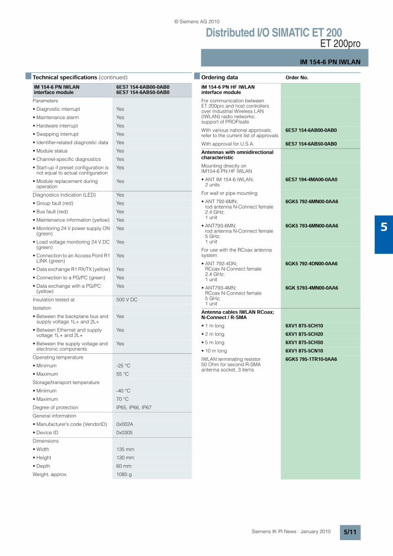
n Technical specifications (continued) n Ordering data Order No.
IM 154-6 PN IWLAN interface module
6ES7 154-6AB00-0AB06ES7 154-6AB50-0AB0
Parameters
• Diagnostic interrupt Yes
• Maintenance alarm Yes
• Hardware interrupt Yes
• Swapping interrupt Yes
• Identifier-related diagnostic data Yes
• Module status Yes
• Channel-specific diagnostics Yes
• Start-up if preset configuration is not equal to actual configuration
Yes
• Module replacement during operation
Yes
Diagnostics indication (LED) Yes
• Group fault (red) Yes
• Bus fault (red) Yes
• Maintenance information (yellow) Yes
• Monitoring 24 V power supply ON (green)
Yes
• Load voltage monitoring 24 V DC (green)
Yes
• Connection to an Access Point R1 LINK (green)
Yes
• Data exchange R1 RX/TX (yellow) Yes
• Connection to a PG/PC (green) Yes
• Data exchange with a PG/PC (yellow)
Yes
Insulation tested at 500 V DC
Isolation
• Between the backplane bus and supply voltage 1L+ and 2L+
Yes
• Between Ethernet and supply voltage 1L+ and 2L+
Yes
• Between the supply voltage and electronic components
Yes
Operating temperature
• Minimum -25 °C
• Maximum 55 °C
Storage/transport temperature
• Minimum -40 °C
• Maximum 70 °C
Degree of protection IP65, IP66, IP67
General information
• Manufacturer’s code (VendorID) 0x002A
• Device ID 0x0305
Dimensions
• Width 135 mm
• Height 130 mm
• Depth 60 mm
Weight, approx. 1085 g
IM 154-6 PN HF IWLAN interface moduleFor communication between ET 200pro and host controllers over Industrial Wireless LAN (IWLAN) radio networks; support of PROFIsafe
With various national approvals; refer to the current list of approvals
6ES7 154-6AB00-0AB0
With approval for U.S.A. 6ES7 154-6AB50-0AB0Antennas with omnidirectional characteristicMounting directly on IM154-6 PN HF IWLAN
• ANT IM 154-6 IWLAN; 2 units
6ES7 194-4MA00-0AA0
For wall or pipe mounting
• ANT 792-6MN;rod antenna N-Connect female 2.4 GHz; 1 unit
6GK5 792-6MN00-0AA6
• ANT793-6MN; rod antenna N-Connect female 5 GHz; 1 unit
6GK5 793-6MN00-0AA6
For use with the RCoax antenna system
• ANT 792-4DN; RCoax N-Connect female 2.4 GHz; 1 unit
6GK5 792-4DN00-0AA6
• ANT793-4MN; RCoax N-Connect female 5 GHz; 1 unit
6GK 5793-4MN00-0AA6
Antenna cables IWLAN RCoax; N-Connect / R-SMA• 1 m long 6XV1 875-5CH10• 2 m long 6XV1 875-5CH20• 5 m long 6XV1 875-5CH50• 10 m long 6XV1 875-5CN10IWLAN terminating resistor 50 Ohm for second R-SMA antenna socket, 3 items
6GK5 795-1TR10-0AA6
Kap_05_en.fm Seite 11 Freitag, 29. Januar 2010 10:12 10
© Siemens AG 2010

Distributed I/O SIMATIC ET 200ET 200pro
IM 154-6 PN IWLAN
5/12 Siemens IK PI News · January 2010
5
n Ordering data Order No. Order No.
n More informationRadio approvalsCurrent approvals can be found in the Internet.
In Germany
http://intranet.automation.siemens.com/net/html_00/ftp/support/lz_laenderliste_wlan_de.pdf
Outside Germany:
http://intranet.automation.siemens.com/net/html_00/ftp/support/lz_laenderliste_wlan_en.pdf
Accessories7/8" connecting cable to power supply5-core, 5 x 1.5 mm2,trailing type, pre-assembled with two 7/8" connectors
• 1.5 m long 6XV1 822-5BH15• 2.0 m long 6XV1 822-5BH20• 3.0 m long 6XV1 822-5BH30• 5.0 m long 6XV1 822-5BH50• 10 m long 6XV1 822-5BN10• 15 m long 6XV1 822-5BN15• Other special lengths with
90° or 180° cable outletSee http://support.automation.siemens.com/WW/view/en/26999294
Power line 6XV1 830-8AH105-core, 5 x 1.5 mm2, trailing type, sold by the meter, minimum order quantity 20 m, maximum order quantity 1,000 m
7/8" cable connector 6GK1 905-0FB00For ET 200eco, with axial cable outlet; with socket insert, pack of 5
Twisted Pair cables 4x2 with RJ45 connectors• 0.5 m long 6XV1 870-3QE50• 1 m long 6XV1 870-3QH10• 2 m long 6XV1 870-3QH20• 6 m long 6XV1 870-3QH60• 10 m long 6XV1 870-3QN10Crossed Twisted Pair cables 4x2 with RJ45 connectors• 0.5 m long 6XV1 870-3RE50• 1 m long 6XV1 870-3RH10• 2 m long 6XV1 870-3RH20• 6 m long 6XV1 870-3RH60• 10 m long 6XV1 870-3RN10IE FC RJ45 Plug 180180° cable outlet;for line components and CPs/CPUs with Industrial Ethernet interface
• 1 pack = 1 item 6GK1 901-1BB10-2AA0• 1 pack = 10 items 6GK1 901-1BB10-2AB0IE FC RJ45 Plug 9090° cable outlet; e.g. for ET 200S
• 1 pack = 1 item 6GK1 901-1BB20-2AA0• 1 pack = 10 items 6GK1 901-1BB20-2AB0
General accessoriesET 200pro rack• Narrow, for interface,
electronics and power modules
- 500 mm 6ES7 194-4GA00-0AA0- 1000 mm 6ES7 194-4GA60-0AA0- 2000 mm, can be cut to length 6ES7 194-4GA20-0AA0
• Compact, for interface, electronics and power modules
- 500 mm 6ES7 194-4GC70-0AA0- 1000 mm 6ES7 194-4GC60-0AA0- 2000 mm, can be cut to length 6ES7 194-4GC20-0AA0
• Wide, for interface, electronics, power modules and motor starters
- 500 mm 6ES7 194-4GB00-0AA0- 1000 mm 6ES7 194-4GB60-0AA0- 2000 mm, can be cut to length 6ES7 194-4GB20-0AA0
• Wide, for I/O modules and motor starters
- 500 mm 6ES7 194-4GD00-0AA0- 1000 mm 6ES7 194-4GD10-0AA0- 2000 mm 6ES7 194-4GD20-0AA0
Spare fuse 6ES7 194-4HB00-0AA012.5 A quick-response, for interface and power modules, 10 items per package unit
Labels 3RT1 900-1SB2020 x 7 mm, pale turquoise, 340 items per pack
SIMATIC Micro Memory Card• 64 KB 6ES7 953-8LF20-0AA0• 128 KB 6ES7 953-8LG11-0AA0• 512 KB 6ES7 953-8LJ20-0AA0SIMATIC Manual Collection 6ES7 998-8XC01-8YE0Electronic manuals on DVD, multi-language: S7-200, TD 200, S7-300, M7-300, C7, S7-400, M7-400, STEP 7, Engineering Tools, Runtime Soft-ware, SIMATIC DP (Distributed I/O), SIMATIC HMI (Human Machine Interface), SIMATIC NET (Industrial Communication)
SIMATIC Manual Collection – Update service for 1 year
6ES7 998-8XC01-8YE2
Scope of supply: Current DVD "S7 Manual Collection" and the three subsequent updates
Kap_05_en.fm Seite 12 Freitag, 29. Januar 2010 10:12 10
© Siemens AG 2010

Distributed I/O SIMATIC ET 200ET 200pro
SIMATIC ET200pro PS
5/13Siemens IK PI News · January 2010
5
n ApplicationThe power supplies with IP67 degree of protection, SITOP PSU300P and SIMATIC ET200pro PS1), serve as electronics/encoder and load power supplies for the new I/O device.
With a signaling contact for "24 V OK" and "Overtemperature", and in the case of SIMATIC ET 200pro with a second plug-in connector for input voltage loop-through.
1) Available with a second plug connector for loop-through of the input voltage as SIMATIC ET 200pro PS (6ES7148-4PC00-0HA0).
n Technical specifications
Power supply, type 24 V/8 A (SIMATIC ET 200pro PS)
Order No. 6ES7 148-4PC00-0HA0Input 3-phase AC
Rated voltage value Vin rated 400/480 V 3 AC Wide-range input
Voltage range 340 ... 550 V (320 ... 340 V for mx. 1 min)
Overvoltage resistance Implemented internally with varistors
Mains buffering at Iout rated > 15 ms at Vin = 400 V
Rated line frequency; range 50/60 Hz; 45 ... 66 Hz
Rated current value Iin rated 0.5 A (at Vin 400 V)
Making current limit (+25 °C) < 40 A
I 2 t < 3.5 A2s
Built-in incoming fuse Internal, 4 A
Required protection in the main supply conductor
With power loop-through fuse ≤ 25 A or circuit breaker e.g. 3RV1021-1DA15 or 3RV1742-5DD10 (UL 489)
Output Controlled DC voltage galvanically connected with PE
Rated voltage value Vout rated 24 V DC
Total tolerance < ±3 ... -5 %
• Static mains compensation Approx. 0.5 %
• Static load balancing Approx. 0.5 %
Residual ripple < 200 mVpp
Spikes (bandwidth: 20 MHz) < 250 mVpp
Adjustment range –
Status display Green LED for 24 V OK
Signaling (max. 30 V, 10 mA) • Power Good (High level 1L+ for Vout in range 21.3 ... 29 V)
• Overtemperature warning at least 30 s before switch-off (High level 1L+ when the max. internal temperature is exceeded)
On/off behavior Overshoot of Vout approx. < 2 %
Startup delay/voltage rise < 1.5 s/< 400 ms
Power supply, type 24 V/8 A (SIMATIC ET 200pro PS)
Order No. 6ES7 148-4PC00-0HA0Rated current value Iout rated 8 ACurrent range
• Up to +60 °C 0 ... 8 A (up to +55 °C)
• Derating –
Dynamic overcurrent on
• Power-up on short circuit Approx. 50 A for 100 ms
• Short circuit during operation Approx. 50 A for 100 ms
Parallel switching for enhanced performance
No
EfficiencyEfficiency at Vout rated, Iout rated Typ. 88 %
Power loss at Vout rated, Iout rated Typ. 25 W
Closed-loop controlDyn. mains compensation(Vin rated ±15 %)
Typ. ±0.5 % Vout
Dynamic load smoothing(Iout: 50/100/50 %)
Typ. ±1 % Vout
Load step settling time
• 50 to 100 % Typ. < 2 ms
• 100 to 50 % Typ. < 2 ms
Protection and monitoringOutput overvoltage protection < 33 V
Current limitation Typ. 9.4 A
Short-circuit protection Electronic shutdown, automatic restart
Sustained short-circuit current rms value
< 10 A
Overload/short-circuit indicator –
SafetyPrimary/secondary isolation Yes, protectiv extra low output
voltage Vout according to EN 60950 and EN 50178
Protection class Class I
Leakage current < 3.5 mA
Safety approval Yes, CB scheme
CE mark Yes
UL/cUL (CSA) approval Prepared for UL-listed (UL 508)
Degree of protection (EN 60529) IP67, enclosure type 4 indoor
Kap_05_en.fm Seite 13 Freitag, 29. Januar 2010 10:12 10
© Siemens AG 2010

Distributed I/O SIMATIC ET 200ET 200pro
SIMATIC ET200pro PS
5/14 Siemens IK PI News · January 2010
5
n Technical specifications (continued)
n Ordering data Order No. Order No.
Power supply, type 24 V/8 A (SIMATIC ET 200pro PS)
Order No. 6ES7 148-4PC00-0HA0EMCEmitted interference EN 55022 Class A
Supply harmonics limitation –
Noise immunity EN 61000-6-2
Operating dataAmbient temperature range -25 ... +55 °C with natural
convection
Transport/storage temperature range
-40 ... +70 °C
Humidity class Climate class 3K3 according to EN 60721, no condensation
Power supply, type 24 V/8 A (SIMATIC ET 200pro PS)
Order No. 6ES7 148-4PC00-0HA0MechanicsConnections
• Supply input L1, L2, L3, PE Plug connector HAN Q4/2The supply input is looped through internally and is made available via a second HAN Q4/2 plug connector.
• Output + 2 x. 1 mm 2 (4-pole cable for +/- with open, labeled ends, 2 x 2.5 mm2)
• Output - 2 × 1 mm 2 (4-pole cable for +/- with open, labeled ends, 2 x 2.5 mm2) M12 plug-in connector, 5-pin
• Status signal Plug connector M12, 5-pole
Dimensions (W x H x D) in mm 310 x 135 x 90 + additional height of connector
Weight, approx. 2.8 kg
Installation Can be mounted onto ET 200pro mounting rail
Accessories Power connector (3RK1911-2BE30 (6 mm2))Power feeder plug(3RK1911-2BF10 (4 mm2))Sealing caps for power socket(3RK1902-0CK00 (1 unit per pack.)), (3RK1902-0CJ00 (10 units per pack.))
SIMATIC ET 200pro PS 6ES7 148-4PC00-0HA0stabilized power supply in the design of the distributed I/O sys-tem, with the possibility of power loop-through to other modules; IP67 degree of protection; Input: 400-480 V 3 ACOutput: 24 V DC/8 A
AccessoriesPower connection plugs for connection to distributed I/O system
• for X1 (6 mm2) 3RK1 911-2BE30• for X2 (6 mm2) 3RK1 911-2BF10Sealing capsfor 9-pole power socket
• X2 (1 unit per pack.) 3RK1 902-0CJ00• X2 (10 units per pack.) 3RK1 902-0CK00
Kap_05_en.fm Seite 14 Freitag, 29. Januar 2010 10:12 10
© Siemens AG 2010

Distributed I/O SIMATIC ET 200ET 200pro
SIMATIC ET200pro PS
5/15Siemens IK PI News · January 2010
5
n Dimensions
G_KT01_XX_00368
310
119
130.5
135.5
300
83.5
Kap_05_en.fm Seite 15 Freitag, 29. Januar 2010 10:12 10
© Siemens AG 2010

Distributed I/O SIMATIC ET 200ET 200eco PN
ET 200eco PN
5/16 Siemens IK PI News · January 2010
5
n Overview
• Compact block I/O for processing digital, analog and IO-Link signals for connecting to the PROFINET bus system
• Cabinet-free design with degree of protection IP65/66/67 with M12 connections
• Very rugged and resistant metal enclosure and encapsulated
• Compact module in two types of enclosures: - 30 mm x 200 mm x 37 mm (W x H x D, long and narrow
enclosure), with 4 x M12 for digital signals - 60 mm x 175 mm x 37 mm (W x H x D, short and wide
enclosure), with 8 x M12 for digital signals and IO-Link- 60 mm x 175 mm x 37 mm (W x H x D, short and wide
enclosure) with 4 x M12 or 8 x M12 for analog signals
• PROFINET connection: 2 x M12 and automatic PROFINET address assignment
• Data transmission rate 100 Mbit/s
• LLDP proximity detection without PG and Fast Startup (boot up within approx 0.5 seconds)
• Supply and load voltage connection: 2 x M12
• Module variance: - 8 DI - 16 DI - 8 DO (2 A) - 8 DO (1.3 A) - 8 DO (0.5 A) - 16 DO (1.3 A) - 8 DI/DO (1.3 A), - 8 AI (U, I, TC, RTD) - 4 AO (U, I) - 4 IO-Link + 8 DI + 4 DO (1.3 A)
• Channel-specific diagnostics
n Technical specifications
6ES7 141-6BF00-0AB0 6ES7 141-6BG00-0AB0 6ES7 141-6BH00-0AB0Supply voltages
Rated value
• DC 24 V Yes Yes Yes
• permissible range, lower limit (DC)
20.4 V 20.4 V 20.4 V
• permissible range, upper limit (DC)
28.8 V 28.8 V 28.8 V
• Reverse polarity protection Yes Yes Yes
Current consumption
Current consumption, typ. 100 mA 100 mA 100 mA
Current consumption/power loss
Power loss, typ. 5.5 W 4.5 W 6.5 W
interfaces
Number of PROFINET interfaces 2 2 2
automatic detection of transmission speed
Yes Yes Yes
Transmission speed, max. 100 Mbit/s 100 Mbit/s 100 Mbit/s
Protocols
PROFINET IO Yes Yes Yes
Protocols (Ethernet)
• SNMP Yes Yes Yes
• DCP Yes Yes Yes
• LLDP Yes Yes Yes
• ping Yes Yes Yes
• arp Yes Yes Yes
Kap_05_en.fm Seite 16 Freitag, 29. Januar 2010 10:12 10
© Siemens AG 2010

Distributed I/O SIMATIC ET 200ET 200eco PN
ET 200eco PN
5/17Siemens IK PI News · January 2010
5
n Technical specifications (continued)
6ES7 141-6BF00-0AB0 6ES7 141-6BG00-0AB0 6ES7 141-6BH00-0AB0Digital inputs
Number of digital inputs 8 8 16
Number of simultanneously controllable inputs
• Number of simultaneously controllable inputs, up to 60 °C
8 8 16
Input voltage
• Rated value, DC 24 V 24 V 24 V
• for signal "0" -3 to +5 V -3 to +5 V -3 to +5 V
• for signal "1" 11 to 30 V 11 to 30 V 11 to 30 V
Input current
• for signal "0", max. (permissible quiescent current)
1.5 mA 1.5 mA 1.5 mA
• for signal "1", typ. 7 mA 7 mA 7 mA
Input delay (for rated value of input voltage)
• for standard inputs
- at "0" to "1", max. Typ. 3 ms Typ. 3 ms Typ. 3 ms
- at "1" to "0", max. Typ. 3 ms Typ. 3 ms Typ. 3 ms
Cable length
• Cable length unshielded, max. 30 m 30 m 30 m
Encoder supply
Number of outputs 4 8 8
Output current, rated value 100 mA; Per output 100 mA; Per output 100 mA; Per output
24 V encoder supply
• Short-circuit protection Yes Yes Yes
Interrupts/diagnostics/status information
Status indicator Yes; Green LED Yes; Green LED Yes; Green LED
Alarms
• Diagnostic alarm Yes Yes Yes
Diagnoses
• Diagnostic functions Yes Yes Yes
• Diagnostic information readable Yes Yes Yes
• Monitoring the voltage supply to the electronics
Yes; Green "ON" LED Yes; Green "ON" LED Yes; Green "ON" LED
• Wire break in signal encoder cable
Yes Yes Yes
• Short circuit encoder supply Yes; Per channel group Yes; Per channel group Yes; Per channel group
• Group error Yes; Red/yellow "SF/MT" LED Yes; Red/yellow "SF/MT" LED Yes; Red/yellow "SF/MT" LED
Isolation
tested with
• 24 V DC circuits 500 V 500 V 500 V
Kap_05_en.fm Seite 17 Freitag, 29. Januar 2010 10:12 10
© Siemens AG 2010

Distributed I/O SIMATIC ET 200ET 200eco PN
ET 200eco PN
5/18 Siemens IK PI News · January 2010
5
n Technical specifications (continued)
6ES7 141-6BF00-0AB0 6ES7 141-6BG00-0AB0 6ES7 141-6BH00-0AB0Isolation
between the load voltages Yes Yes Yes
between load voltage and all other switching components
No No No
between Ethernet and electronics Yes Yes Yes
Galvanic isolation, digital inputs
• between the channels No No No
Permissible potential difference
between different circuits 75 V DC/60 V AC 75 V DC/60 V AC 75 V DC/60 V AC
Degree of protection
IP 65 Yes Yes Yes
IP 66 Yes Yes Yes
IP 67 Yes Yes Yes
General information
Vendor identification (VendorID) 002AH 002AH 002AH
Device identifier (DeviceID) 0306H 0306H 0306H
Dimensions and weight Dimensions and weight
• Width 30 mm 60 mm 60 mm
• Height 200 mm 175 mm 175 mm
• Depth 49 mm 49 mm 49 mm
Weight
• Weight 550 g 910 g 910 g
6ES7 142-6BF50-0AB0
6ES7 142-6BF00-0AB0
6ES7 142-6BG00-0AB0
6ES7 142-6BR00-0AB0
6ES7 142-6BH00-0AB0
Supply voltages
Load voltage 1L+
• Rated value (DC) 24 V 24 V 24 V 24 V 24 V
• Reverse polarity protection Yes Yes Yes Yes Yes
Load voltage 2L+
• Rated value (DC) 24 V 24 V 24 V 24 V 24 V
• Reverse polarity protection Yes Yes Yes Yes Yes
Current consumption
from load voltage 1L+ (unswitched voltage)
100 mA 4 A 4 A 4 A 4 A
Current consumption/power loss
Power loss, typ. 3 W 5.5 W 5.5 W 5 W 5.5 W
Kap_05_en.fm Seite 18 Freitag, 29. Januar 2010 10:12 10
© Siemens AG 2010

Distributed I/O SIMATIC ET 200ET 200eco PN
ET 200eco PN
5/19Siemens IK PI News · January 2010
5
n Technical specifications (continued)
6ES7 142-6BF50-0AB0
6ES7 142-6BF00-0AB0
6ES7 142-6BG00-0AB0
6ES7 142-6BR00-0AB0
6ES7 142-6BH00-0AB0
Interfaces
Number of PROFINET interfaces 2 2 2 2 2
automatic detection of transmission speed
Yes Yes Yes Yes Yes
Autocrossing Yes Yes Yes Yes Yes
Transmission speed, max. 100 Mbit/s 100 Mbit/s 100 Mbit/s 100 Mbit/s 100 Mbit/s
Connection point M12 Yes Yes Yes Yes Yes
Protocols
PROFINET IO Yes Yes Yes Yes Yes
Protocols (Ethernet)
• SNMP Yes Yes Yes Yes Yes
• DCP Yes Yes Yes Yes Yes
• LLDP Yes Yes Yes Yes Yes
• ping Yes Yes Yes Yes Yes
• arp Yes Yes Yes Yes Yes
Digital outputs
Number of digital outputs 8 8 8 8 16
Short-circuit protection of the output
Yes; Electronic Yes; Electronic Yes; Electronic Yes; Electronic Yes; Electronic
• Response threshold, typ. 0.7 A 1.8 A 1.8 A 2.8 A 1.8 A
Limitation of inductive shutdown voltage to
Typ. (L1+, L2+) -47 V
Typ. (L1+, L2+) -47 V
Typ. (L1+, L2+) -47 V
Typ. (L1+, L2+) -47 V
Typ. (L1+, L2+) -47 V
Switching capacity of the outputs
• on lamp load, max. 5 W 5 W 5 W 10 W 5 W
Controlling a digital input Yes Yes Yes Yes Yes
Output current
• for signal "1" rated value 0.5 A 1.3 A; maximum 1.3 A; maximum 2 A 1.3 A; maximum
• for signal "0" residual current, max.
1.5 mA 1.5 mA 1.5 mA 1.5 mA 1.5 mA
Parallel switching of 2 outputs
• for increased power No No No No No
• for redundant control of a load Yes Yes Yes Yes Yes
Switching frequency
• with resistive load, max. 100 Hz 100 Hz 100 Hz 100 Hz 100 Hz
• with inductive load, max. 0.5 Hz 0.5 Hz 0.5 Hz 0.5 Hz 0.5 Hz
• on lamp load, max. 1 Hz 1 Hz 1 Hz 1 Hz 1 Hz
Aggregate current of the outputs (per group)
• up to 55 °C, max. 3.9 A
• up to 60 °C, max. 4 A 2.6 A 3.9 A 3.9 A 3.9 A
Cable length
• Cable length unshielded, max. 30 m 30 m 30 m 30 m 30 m
Kap_05_en.fm Seite 19 Freitag, 29. Januar 2010 10:12 10
© Siemens AG 2010

Distributed I/O SIMATIC ET 200ET 200eco PN
ET 200eco PN
5/20 Siemens IK PI News · January 2010
5
n Technical specifications (continued)
6ES7 142-6BF50-0AB0
6ES7 142-6BF00-0AB0
6ES7 142-6BG00-0AB0
6ES7 142-6BR00-0AB0
6ES7 142-6BH00-0AB0
Interrupts/diagnostics/status information
Status indicator Yes; Green LED Yes; Green LED Yes; Green LED Yes; Green LED Yes; Green LED
Alarms
• Diagnostic alarm Yes Yes Yes Yes Yes
Diagnoses
• Diagnostic functions Yes Yes Yes Yes Yes
• Diagnostic information readable Yes Yes Yes Yes Yes
• Monitoring the voltage supply to the electronics
Yes; Green "ON" LED
Yes; Green "ON" LED
Yes; Green "ON" LED
Yes; Green "ON" LED
Yes; Green "ON" LED
• Wire break in acutator cable Yes Yes Yes Yes Yes
• Short circuit Yes Yes Yes Yes Yes
• Group error Yes; Red/yellow "SF/MT" LED
Yes; Red/yellow "SF/MT" LED
Yes; Red/yellow "SF/MT" LED
Yes; Red/yellow "SF/MT" LED
Yes; Red/yellow "SF/MT" LED
Isolation
tested with
• 24 V DC circuits 500 V 500 V 500 V 500 V 500 V
Isolation
between the load voltages Yes Yes Yes Yes Yes
between load voltage and all other switching components
No No No No No
between Ethernet and electronics Yes Yes Yes Yes Yes
Isolation, digital outputs
• between the channels No No No No No
Permissible potential difference
between different circuits 75 V DC/60 V AC 75 V DC/60 V AC 75 V DC/60 V AC 75 V DC/60 V AC 75 V DC/60 V AC
Degree of protection
IP 65 Yes Yes Yes Yes Yes
IP 66 Yes Yes Yes Yes Yes
IP 67 Yes Yes Yes Yes Yes
General information
Vendor identification (VendorID) 002AH 002AH 002AH 002AH 002AH
Device identifier (DeviceID) 0306H 0306H 0306H 0306H 0306H
Dimensions and weight Dimensions and weight
• Width 30 mm 30 mm 60 mm 60 mm 60 mm
• Height 200 mm 200 mm 175 mm 175 mm 175 mm
• Depth 49 mm 49 mm 49 mm 49 mm 49 mm
Weight
• Weight 550 g 550 g 910 g 910 g 910 g
Kap_05_en.fm Seite 20 Freitag, 29. Januar 2010 10:12 10
© Siemens AG 2010

Distributed I/O SIMATIC ET 200ET 200eco PN
ET 200eco PN
5/21Siemens IK PI News · January 2010
5
n Technical specifications (continued)
6ES7 147-6BG00-0AB0Supply voltages
Rated value
• 24 V DC Yes
• Permissible range, lower limit (DC)
20.4 V
• Permissible range, upper limit (DC)
28.8 V
• Reverse polarity protection Yes
Load voltage 2L+
• Rated value (DC) 24 V
• Permissible range, lower limit (DC)
20.4 V
• Permissible range, upper limit (DC)
28.8 V
• Reverse polarity protection Yes
Current consumption
from load voltage 1L+ (unswitched voltage)
4 A
from load voltage 2L+, max. 4 A
Current consumption/power loss
Power loss, typ. 6.5 W
interfaces
Number of PROFINET interfaces 2
automatic detection of transmission speed
Yes
Autocrossing Yes
Integrated switch Yes
Transmission rate, max. 100 Mbit/s
Connection point M12 Yes
Protocols
PROFINET IO Yes
Protocols (Ethernet)
• SNMP Yes
• DCP Yes
• LLDP Yes
• ping Yes
• arp Yes
PROFINET IO-Device
with option "high flexibility", supported
Yes
Prioritized power up, supported Yes
Digital inputs
Number of digital inputs 8
• in groups of 4
6ES7 147-6BG00-0AB0Number of simultanneously controllable inputs
• all mounting positions
- Number of simultaneously controllable inputs, up to 60 °C
8
Input characteristic according to IEC 1131, type 3
Yes
Input voltage
• Rated value, DC 24 V
• for signal "0" -3 to +5 V
• for signal "1" 11 to 30 V
Input current
• for signal "0", max. (permissible quiescent current)
1.5 mA
• for signal "1", typ. 7 mA
Cable length
• Cable length unshielded, max. 30 m
Digital outputs
Number of digital outputs 8
• in groups of 4
Short-circuit protection Yes
Switching capacity of the outputs
• on lamp load, max. 5 W
Controlling a digital input Yes
Output current
• for signal "1" rated value 1.3 A; maximum
• for signal "0" residual current, max.
1.5 mA
Parallel switching of 2 outputs
• for increased power No
• for redundant control of a load Yes
Switching frequency
• with resistive load, max. 100 Hz
• with inductive load, max. 0.5 Hz
• on lamp load, max. 1 Hz
Aggregate current of the outputs (per group)
• up to 60 °C, max. 3.9 A
Cable length
• Cable length unshielded, max. 30 m
Encoder supply
Number of outputs 8
Output current, rated value 100 mA; per output
24 V encoder supply
• Short-circuit protection Yes
Kap_05_en.fm Seite 21 Freitag, 29. Januar 2010 10:12 10
© Siemens AG 2010

Distributed I/O SIMATIC ET 200ET 200eco PN
ET 200eco PN
5/22 Siemens IK PI News · January 2010
5
n Technical specifications (continued)
6ES7 147-6BG00-0AB0Interrupts/diagnostics/status information
Status indicator Yes; green LED
Alarms
• Diagnostic alarm Yes
Diagnoses
• Diagnostics functions Yes
• Diagnostics information readable Yes
• Monitoring the voltage supply of the electronics
Yes; green LED "ON"
• Wire break in acutator cable Yes
• Wire break in signal encoder cable
Yes
• Short circuit Yes
• Short circuit encoder supply Yes
• Group error Yes; red/yellow LED "SF/MT"
Isolation
tested with
• 24 V DC circuits 500 V
• Interface 1 500 µV; according to IEEE 802.3
Isolation
between the load voltages Yes
between load voltage and all other switching components
No
between Ethernet and electronics Yes
Galvanic isolation, digital inputs
• between the channels No
Isolation, digital outputs
• between the channels No
Degree of protection
IP 65 Yes
IP 66 Yes
IP 67 Yes
Dimensions and weight Dimensions and weight
• Width 60 mm
• Height 175 mm
• Depth 49 mm
Weight
• Weight 910 g
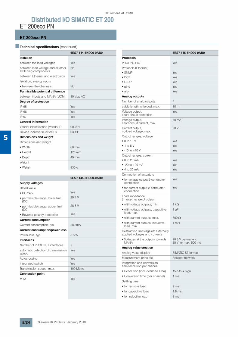
6ES7 144-6KD00-0AB0Supply voltages
Rated value
• DC 24 V Yes
• permissible range, lower limit (DC)
20.4 V
• permissible range, upper limit (DC)
28.8 V
• Reverse polarity protection Yes
Current consumption
Current consumption, typ. 110 mA
Current consumption/power loss
Power loss, typ. 2.8 W
Interfaces
Number of PROFINET interfaces 2
automatic detection of transmission speed
Yes
Transmission speed, max. 100 Mbit/s
Connection point M12 Yes
Protocols
PROFINET IO Yes
Protocols (Ethernet)
• SNMP Yes
• DCP Yes
• LLDP Yes
• ping Yes
• arp Yes
Analog inputs
Number of analog inputs 8
Number of analog inputs for voltage/current measurement
4
Number of analog inputs for resis-tance/temperature measurement
4
cable length, shielded, max. 30 m
Input ranges (rated values), voltages
• 0 to +10 V Yes
• 1 to 5 V Yes
• -10 V to +10 V Yes
• -80 mV to +80 mV Yes
Kap_05_en.fm Seite 22 Freitag, 29. Januar 2010 10:12 10
© Siemens AG 2010

Distributed I/O SIMATIC ET 200ET 200eco PN
ET 200eco PN
5/23Siemens IK PI News · January 2010
5
n Technical specifications (continued)
6ES7 144-6KD00-0AB0Input ranges (rated values), currents
• 0 to 20 mA Yes
• -20 to +20 mA Yes
• 4 to 20 mA Yes
Input ranges (rated values), thermoelements
• Type E Yes
• Type J Yes
• Type K Yes
• Type N Yes
Input ranges (rated values), resistance thermometers
• Ni 100 Yes
• Ni 1000 Yes
• Ni 120 Yes
• Ni 200 Yes
• Ni 500 Yes
• Pt 100 Yes
• Pt 1000 Yes
• Pt 200 Yes
• Pt 500 Yes
Input ranges (rated values), resistors
• 0 to 150 Ohm Yes
• 0 to 300 Ohm Yes
• 0 to 600 Ohm Yes
• 0 to 3000 Ohm Yes
Voltage input
• permissible input frequency for voltage input (destruction limit), max.
28.8 V permanent, 35 V for max. 500 ms
Temperature compensation
• programmable Yes
• internal temperature compensation
Yes
• external temperature compensa-tion with compensations socket
Yes
Analog value creation
Analog value display SIMATIC S7 format
Measurement principle Integrating
Integration and conversion time/resolution per channel
• Resolution (incl. overload area) 15 bits + sign
• Integration time, parameterizable Yes
• Integration time, ms 2 / 16.67 / 20 / 100 ms
• Interference voltage suppression for interference frequency f1 in Hz
500 / 60 / 50 / 10 Hz
• Conversion time (per channel) 4 / 19 / 22 / 102 ms
Smoothing of measured values
• parameterizable Yes
• Level: none Yes; 1 x cycle time
• Level: weak Yes; 4 x cycle time
• Level: middle Yes; 16 x cycle time
• Level: strong Yes; 64 x cycle time
6ES7 144-6KD00-0AB0Encoder supply
Number of outputs 4
24 V encoder supply
• Short-circuit protection Yes; Electronic at 1.4 A
• Output current, max. 1 A
Encoder Number of connectable encoders, max.
8
Connection of signal encoders
• for voltage measurement Yes
• for current measurement as 2-wire transducer
Yes
• for current measurement as 4-wire transducer
Yes
• for resistance measurement with 2-conductor connection
Yes
• for resistance measurement with 3-conductor connection
Yes
• for resistance measurement with 4-conductor connection
Yes
Errors/accuracies
linearity error (based on input rage)
+/- 0,01 %
Temperature error (relative to input areas)
U: 0,0035%/°C; I:0,006%/°C; RTD: 0,0005%/°C; TC: 0,0035%/°C
Crosstalk between the inputs, min. 85 dB
Interference voltage suppression for f = n x (fl +/- 1 %), fl = interference frequency
• Series mode interference (peak value of interference < rated value of input range), min.
46 dB
• common mode voltage, min. 70 dB
Interrupts/diagnostics/status information
Alarms
• Diagnostic alarm Yes
Diagnoses
• Diagnostic functions Yes
• Diagnostic information readable Yes
• Monitoring the voltage supply to the electronics
Yes; Green "ON" LED
• Short circuit encoder supply Yes; Per module
• Group error Yes; Red/yellow "SF/MT" LED
• Overflow/underflow Yes
Isolation
tested with
• 24 V DC circuits 500 V
• Interface 1 500 V; according to IEEE 802.3
Kap_05_en.fm Seite 23 Freitag, 29. Januar 2010 10:12 10
© Siemens AG 2010
Distributed I/O SIMATIC ET 200ET 200eco PN
ET 200eco PN
5/24 Siemens IK PI News · January 2010
5
n Technical specifications (continued)
6ES7 144-6KD00-0AB0Isolation
between the load voltages Yes
between load voltage and all other switching components
No
between Ethernet and electronics Yes
Isolation, analog inputs
• between the channels No
Permissible potential differencebetween inputs and MANA (UCM) 10 Vpp AC
Degree of protection IP 65 Yes
IP 66 Yes
IP 67 Yes
General information
Vendor identification (VendorID) 002AH
Device identifier (DeviceID) 0306H
Dimensions and weight Dimensions and weight
• Width 60 mm
• Height 175 mm
• Depth 49 mm
Weight
• Weight 930 g
6ES7 145-6HD00-0AB0Supply voltages
Rated value
• DC 24 V Yes
• permissible range, lower limit (DC)
20.4 V
• permissible range, upper limit (DC)
28.8 V
• Reverse polarity protection Yes
Current consumption
Current consumption, typ. 280 mA
Current consumption/power loss
Power loss, typ. 5.5 W
Interfaces
Number of PROFINET interfaces 2
automatic detection of transmission speed
Yes
Autocrossing Yes
integrated switch Yes
Transmission speed, max. 100 Mbit/s
Connection point M12 Yes
6ES7 145-6HD00-0AB0Protocols
PROFINET IO Yes
Protocols (Ethernet)
• SNMP Yes
• DCP Yes
• LLDP Yes
• ping Yes
• arp Yes
Analog outputs
Number of analg outputs 4
cable length, shielded, max. 30 m
Voltage output, short-circuit protection
Yes
Voltage output, short-circuit current, max.
30 mA
Current output, no-load voltage, max.
20 V
Output ranges, voltage
• 0 to 10 V Yes
• 1 to 5 V Yes
• -10 to +10 V Yes
Output ranges, current
• 0 to 20 mA Yes
• -20 to +20 mA Yes
• 4 to 20 mA Yes
Connection of actuators
• for voltage output 2-conductor connection
Yes
• for current output 2-conductor connection
Yes
Load impedance (in rated range of output)
• with voltage outputs, min. 1 kΩ
• with voltage outputs, capacitive load, max.
1 µF
• with current outputs, max. 600 Ω
• with current outputs, inductive load, max.
1 mH
Destruction limits against externally applied voltages and currents
• Voltages at the outputs towards MANA
28.8 V permanent, 35 V for max. 500 ms
Analog value creationAnalog value display SIMATIC S7 format
Measurement principle Resistor network
Integration and conversion time/resolution per channel
• Resolution (incl. overload area) 15 bits + sign
• Conversion time (per channel) 1 ms
Settling time
• for resistive load 2 ms
• for capacitive load 1.8 ms
• for inductive load 2 ms
Kap_05_en.fm Seite 24 Freitag, 29. Januar 2010 10:12 10
© Siemens AG 2010

Distributed I/O SIMATIC ET 200ET 200eco PN
ET 200eco PN
5/25Siemens IK PI News · January 2010
5
n Technical specifications (continued)
6ES7 145-6HD00-0AB0Encoder supply
Number of outputs 4
24 V encoder supply
• Short-circuit protection Yes; Electronic at 1.4 A
• Output current, max. 1 A
Errors/accuracies
Output ripple (based on output range, bandwidth 0 to 50 kHz)
U: ±0.6 mVrms; I: ±0.4 nArms
Temperature error (relative to output area)
U: 0.001%/°C; I: 0.0025%/°C
Crosstalk between the outputs, min.
70 dB
Interrupts/diagnostics/status information
Status indicator Yes
Substitute values connectable Yes
Alarms
• Diagnostic alarm Yes
Diagnoses
• Diagnostic functions Yes
• Diagnostic information readable Yes
• Monitoring the voltage supply to the electronics
Yes; Green "ON" LED
• Wire break Yes; Channel-by-channel with current output
• Short circuit Yes; Channel-by-channel with voltage output
• Group error Yes; Red/yellow "SF/MT" LED
Isolation
between the load voltages Yes
between load voltage and all other switching components
No
between Ethernet and electronics Yes
Isolation, analog outputs
• between the channels No
Permissible potential difference
between M internally and the outputs
10 Vpp AC
Degree of protection
IP 65 Yes
IP 66 Yes
IP 67 Yes
General information
Vendor identification (VendorID) 002AH
Device identifier (DeviceID) 0306H
Dimensions and weight Dimensions and weight
• Width 60 mm
• Height 175 mm
• Depth 49 mm
Weight
• Weight 930 g
6ES7 148-6JA00-0AB0Supply voltages
Rated value
• 24 V DC Yes
• Permissible range, lower limit (DC)
20.4 V
• Permissible range, upper limit (DC)
28.8 V
• Reverse polarity protection Yes
Load voltage 2L+
• Rated value (DC) 24 V
• Permissible range, lower limit (DC)
20.4 V
• Permissible range, upper limit (DC)
28.8 V
• Reverse polarity protection Yes
Current consumption
from load voltage 1L+(unswitched voltage)
4 A
from load voltage 2L+, max. 4 A
Current consumption/power loss
Power loss, typ. 8 W
Interfaces
Number of PROFINET interfaces 2
automatic detection of transmission speed
Yes
Autocrossing Yes
integrated switch Yes
Transmission rate, max. 100 Mbit/s
Connection point M12 Yes
Protocols
PROFINET IO Yes
Protocols (Ethernet)
• SNMP Yes
• DCP Yes
• LLDP Yes
• ping Yes
• arp Yes
PROFINET IO-Device
IRT with option "high flexibility", supported
Yes
Digital inputs
Number of digital inputs 8
Number of simultanneously controllable inputs
• all mounting positions
- Number of simultaneously controllable inputs, up to 60 °C
8
Input characteristic according to IEC 1131, type 3
Yes
Input voltage
• Rated value, DC 24 V
• for signal "0" -3 to +5 V
• for signal "1" 11 to 30 V
Kap_05_en.fm Seite 25 Freitag, 29. Januar 2010 10:12 10
© Siemens AG 2010

Distributed I/O SIMATIC ET 200ET 200eco PN
ET 200eco PN
5/26 Siemens IK PI News · January 2010
5
n Technical specifications (continued)
6ES7 148-6JA00-0AB0Input current
• for signal "0", max. (permissible quiescent current)
1.5 mA
• for signal "1", typ. 7 mA
Cable length
• Cable length unshielded, max. 30 m
Digital outputs
Number of digital outputs 4
Short-circuit protection Yes
Switching capacity of the outputs
• on lamp load, max. 5 W
Controlling a digital input Yes
Output current
• for signal "1" rated value 1.3 A; maximum
• for signal "0" residual current, max.
1.5 mA
Parallel switching of 2 outputs
• for increased power No
• for redundant control of a load Yes
Switching frequency
• with resistive load, max. 100 Hz
• with inductive load, max. 0.5 Hz
• on lamp load, max. 1 Hz
Aggregate current of the outputs (per group)
• up to 60 °C, max. 3.9 A
Cable length
• Cable length unshielded, max. 30 m
Encoder supply
Number of outputs 6
Output current, rated value 200 mA; 100 mA per output on X5-X6
24 V encoder supply
• Short-circuit protection Yes
6ES7 148-6JA00-0AB0Interrupts/diagnostics/status information
Status indicator Yes; green LED
Alarms
• Diagnostic alarm Yes
Diagnoses
• Diagnostics functions Yes
• Diagnostics information readable Yes
• Monitoring the voltage supply of the electronics
Yes; green LED "ON"
• Wire break in acutator cable Yes
• Wire break in signal encoder cable
Yes
• Short circuit Yes
• Short circuit encoder supply Yes
• Group error Yes; red/yellowLED "SF/MT"
Isolation
tested with
• 24 V DC circuits 500 V
• interface 1 500 µV; according to IEEE 802.3
Isolation
between the load voltages Yes
between load voltage and all other switching components
No
between Ethernet and electronics Yes
Galvanic isolation, digital inputs
• between the channels No
Isolation, digital outputs
• between the channels No
Degree of protection IP 65 Yes
IP 66 Yes
IP 67 Yes
Dimensions and weight Dimensions and weight
• Width 60 mm
• Height 175 mm
• Depth 49 mm
Weight
• Weight 910 g
Kap_05_en.fm Seite 26 Freitag, 29. Januar 2010 10:12 10
© Siemens AG 2010

Distributed I/O SIMATIC ET 200ET 200eco PN
ET 200eco PN
5/27Siemens IK PI News · January 2010
5
n Ordering data Order No. Order No.
ET 200eco PN digital input module• 8 DI 24 V DC;
4 x M12, dual assignment, degree of protection IP67
6ES7 141-6BF00-0AB0
• 8 DI 24 V DC; 8 x M12, degree of protection IP67
6ES7 141-6BG00-0AB0
• 16 DI 24 V DC; 8 x M12, dual assignment, degree of protection IP67
6ES7 141-6BH00-0AB0
ET 200eco PN digital output module• 8 DO 24 V DC/0.5 A;
4 x M12, dual assignment, 1 load voltage supply DO;degree of protection IP67
6ES7 142-6BF50-0AB0
• 8 DO 24 V DC/1.3 A; 4 x M12, dual assignment, degree of protection IP67
6ES7 142-6BF00-0AB0
• 8 DO 24 V DC/1.3 A; 8 x M12, degree of protection IP67
6ES7 142-6BG00-0AB0
• 8 DO 24 V DC/2 A; 8 x M12, degree of protection IP67
6ES7 142-6BR00-0AB0
• 16 DO 24 V DC/1.3 A; 8 x M12, dual assignment, degree of protection IP67
6ES7 142-6BH00-0AB0
ET 200eco PN digital input/output modules• 8 DI/DO 24 V DC/1.3 A;
8 x M12, degree of protection IP67
6ES7 147-6BG00-0AB0
ET 200eco PN analoginput modules• 8 AI 4 U/I + 4 RTD/TC; 8 x M12,
degree of protection IP676ES7 144-6KD00-0AB0
ET 200eco PN analog output modules• 4 AO U/I; 4 x M12,
degree of protection IP676ES7 145-6HD00-0AB0
ET 200eco PN IO-Link master module• 4 IO-L + 8 DI +
4 DO 24 V DC/1.3 A; 8 x M12, degree of protection IP67
6ES7 148-6JA00-0AB0
Accessories• PD voltage distributor, 24 V DC;
1 X 7/8“, 4 X M126ES7 148-6CB00-0AA0
• Terminal block for ET 200eco PN, 10 A insulation piercing connecting devices
6ES7 194-6CA00-0AA0
• Spare fuses for terminal block, 10 units
6ES7 194-6HB00-0AA0
• Mounting rail 0.5 m 6ES7 194-6GA00-0AA0• Profile screw for mounting rail,
50 units6ES7 194-6MA00-0AA0
• Cap M12 for modules IP67, 10 units
3RK1 901-1KA00
• Labels 10 × 7 mm, pastel turquoise, 816 units
3RT1 900-1SB10
Accessories (continued)
IE FC TP Standard Cable GP 2 x 2 (Type A)
6XV1 840-2AH104-core, shielded TP installation cable for connection to IE FC Outlet RJ45/ IE FC RJ45 Plug; PROFINET-compatible; with UL approval; Sold by the meter;max. length 1000 m, minimum order 20 m
IE FC TP Trailing Cable GP 2 x 2 (Type C)
6XV1 870-2D4-core, shielded TP installation cable for connection to IE FC Outlet RJ45/ IE FC RJ45 Plug for use in trailing cables; PROFINET-compatible; with UL approval; Sold by the meter;max. length 1000 m,minimum order 20 m
PROFINET M12 connector, can be assembledIE FC M12 connector PRO, can be assembled
• 1 unit 6GK1 901-0DB20-6AA0• 8 units 6GK1 901-0DB20-6AA8PROFINET M12 connecting cablesPre-assembled connecting cable with two M12 connectors (D-coded) in various lengths:
• 0.3 m 6XV1 870-8AE30• 0.5 m 6XV1 870-8AE50• 1.0 m 6XV1 870-8AH10• 1.5 m 6XV1 870-8AH15• 2.0 m 6XV1 870-8AH20• 3.0 m 6XV1 870-8AH30• 5.0 m 6XV1 870-8AH50• 10.0 m 6XV1 870-8AN10• 15.0 m 6XV1 870-8AN15M12 connector for load supply 24 V DCConnection socket for infeed of 24 V DC; 4-pin, A-coded, 3 units
6GK1 907-0DC10-6AA3
Connector for passing on the 24 V DC; 4-pin, A-coded, 3 units
6GK1 907-0DB10-6AA3
M12 power connection cablesPre-assembled power connection cables on both sides with M12 socket and connector 4 x 0.75 mm2, in various lengths:
• 0.3 m 6XV1 801-5DE30• 0.5 m 6XV1 801-5DE50• 1.0 m 6XV1 801-5DH10• 1.5 m 6XV1 801-5DH15• 2.0 m 6XV1 801-5DH20• 3.0 m 6XV1 801-5DH30• 5.0 m 6XV1 801-5DH50• 10.0 m 6XV1 801-5DN10• 15.0 m 6XV1 801-5DN15
Kap_05_en.fm Seite 27 Freitag, 29. Januar 2010 10:12 10
© Siemens AG 2010

Distributed I/O SIMATIC ET 200ET 200eco PN
ET 200eco PN
5/28 Siemens IK PI News · January 2010
5
n Ordering data Order No. Order No.
n
M12 coupling plugCan be assembled
• for connecting actuators or sensors, 4-pin
3RX8 000-0CD40
• for connecting actuators or sensors, 5-pin
3RX8 000-0CD55
M12 angular circular connectorCan be assembled; for connecting actuators or sensors, 5-pin
3RX8 000-0CE55
Y cable M12for double connection of I/O by means of single cable to ET 200, 5-pin
6ES7 194-6KA00-0XA0
M12 connecting cables (PUR jacket)Pre-assembled connecting cables for connecting digital sensors and actuators
on both sides with M12 socket and connector 3 x 0.34 mm2, in various lengths:
• 0.6 m 3RX8 000-0GF32-1AA6• 1.0 m 3RX8 000-0GF32-1AB0• 1.5 m 3RX8 000-0GF32-1AB5on both sides with M12 socket and connector 4 x 0.34 mm2, in various lengths:
• 0.6 m 3RX8 000-0GF42-1AA6• 1.0 m 3RX8 000-0GF42-1AB0• 1.5 m 3RX8 000-0GF42-1AB5
Kap_05_en.fm Seite 28 Freitag, 29. Januar 2010 10:12 10
© Siemens AG 2010