distributed by - defense technical information center determination of aircraft cabin radiation,...
TRANSCRIPT

AD-785 646
DETERMINATION OF AIRCRAFT CABIN RADIATION,CONDUCTION, AND CONVECTION HEAT TRANSFERCOEFFICIENTS
Emmett J. Laing
Army Aviation Systems Test ActivityEdwards Air Force Base, California
!97 4
DISTRIBUTED BY:
U. S& DEPARTMVENT OF CMERCEE
Best Available, Copy MpdRA W snwVaW5

LAING
DETERMINATION OF AIRCRAFT CABIN RADIATION,"CONDUCTION, AND CONVECTIONHEAT TRANSFER COEFF1CIENTS
Emmett J. LaingUnited States Army Aviation Systems Test Activity
Edwards Air Force Base, California
NOTATION
","A Aircraft cabin transparent area, ft2
C Heat capacity, BTU/OF-ft 2
Eex Total external radiatioei, BTU/hr-ft 2
-Es Solar radiation, BTU/hr-ft 2
Kc Conduction heat transfer coefficient, *F-hr-ft2/BTUKr Radiation heat transfer coefficient, 'F-hr-ft 2/BTUTa Ambient air temperature, OR.Tc Transient aircraft cabin temperature, ORSTO Initial aircraft cabin temperature, ORT ••s Steady-state aircraft cabin temperature, ORt Time, hrV Aircraft cabin volume, ft3
a cStefan-Boltzman constant, BTU/hr-ft 2-*R4
P.-
1 4
KiKRwroducd by C
NATIONAL TECHNICAL .79INFORMATION SERVICEU 8 o.4Prtment of CommorCe
Springfield VA 22151
.................................. ':" " .

LAING
k. INTRODUCTION
I tf To pn,.periy design aircraft instruments, avionics, and other equipment, which isinqtalled in aircraft cabin areas, it is necessary to accurately know the cabin temperatureenvirornmer !. Aircraft cabin temperatures vary widely depending on the aircraft operating
'corttion, basic design parameters, and type of environmental control system installed.Previous tes'; at the United States Army Aviation Systems Test Activity (USAASTA)"have shown that the highest cabin temperatures frequently occur with the aircraft static
* in zn environment with both high solar radiation and high ambient air temperatures(refs I through 5). It is suspected that high aircraft cabin static temperatures mayincrease aircraft component failure rates, cause equipment to temporarily malfunction,and directly cause equipment failure. However, accuate temperature data for the static
* environment are not available for many aircraft. To obtain this type of data, USAASTA,with the assistance of the United States Army Air Mobility Research and DevelopmentLaboratory, Eustis Directorate, has conducted comprehensive static temperature surveyson five first-line United States Army helicopters.
Lack of readily available test chamber facilities, which would allow a closelycontrolled environmental test, dictated the use of the available natural environment.To increase the accuracy of performing static temperature testing under naturalconditions, a test method was developed which allowed the determination of combinedconduction, convection, and radiation heat transfer coefficients for an aircraft cabin.Once these coefficients have been determined, the cabin static termiperatures can becalculated for any natural conditions, allowing comparison of data gathered at differentconditions and standardization of data to identical envhonmental conditions.References I through 5 are the formal published USAASTA reports from which thestatic temperature data in this paper are taken. It is anticipated that the test methodand data presented in this paper will play an important role in the conduct of futurestatic temperature testing, and increase the understandinA and control -of the aircraftcabin static temperature environment.
7/ AIRCRAFT CABIN STATIC TEMPERATURES
Table I lists the physical characteilstics of the helicopters tested pertinent to theheat transfer properties of the cabin. The most significant characteristic applicable tothe static temperature environment is the ratio of cabin transparent area to cabin volume.In general, the lar.er the area-to-volume ratio, the higher t~m cabin static temperaturewill be. Figures I a 'd 2 show photographs of two UrAted States Army helicopters withlarge amounts of transparent area which are present for maximum visibility. Thetransparent area in all of the helicopters tested is plastic, with the approximate radiationtransmissibility characteristics shown in flguo 3. These characteristics, together withcabin closure, result in the so-called "greenhouse" effect, which allows solar radiationto increase cabin temperatures above the ambient air temperature. Figure 4 shows the
10
1.80
ro s /• L 1 • . . ... .. L , .! • n w s m w m m • m • m ~ • s • • mw • t W , ~ l •

LAING
5-45
Figue 1. OH.6A Helicopter. Figur 2. AH.1G Helicopter.
so
4W
/ ~~~~%LAR *AfleAvio WAVULUNBIfWXWMIUN 10L1 WAMIAT VAVIUier-ca
Thur. 3. Tvupka TranaWivity Figur 4. Typkca Slar Radition atC o krf rnp~tAm&a at the Earth's Surface.
4k4

LAING
solar radiation spectral distribution at the earth's surface. As shown in figure 3, theplastic is transparent to the solar radiation, which, after it passes through the plastic,is both absorbed, reemitted, and reflected by the cabin equipment and internal structure.The reflected radiation exits the cabin through the plastic but the absorbed radiationis reemitted at a lower temperature and longer wavelengths, to which the plastic isnot transparent. Thus the transparent areas in effect trap reemitted solar radiation inthe cabin and cause the cabin temperature to rise until the heat loss rate by meansof cabin skin conduction to the atmosphere and cabin surface radiation is equal tothe heat gain rate from solar radiation.
Figure 5 presents solar radiation data for the continental United States formaximum values during the winter and summer (ref 6). These data can be used todetermine the solar radiation environment to which aircraft are subjected and todetermine environmental test conditions and test geographical locations. Only a limitedamount of world-wide solar radiation data are available (refs 7 and 8); however, theavailable data indicate that the maximum solar radiation values obtained in thecontinental United States are as severe as those obtained anywhere else in the world.The highest solar radiation values in the United States generally occur in the westernhigh desert areas. Current United States Army tactics consider operation in theenvironments of Central Europe and Central Asia. As a matter of reference, the solarradiation and temperature environments of the Federal Republic of Germany and ofIran approximate the environments of the New England and western desert regions ofthe United States, respectively.
Table 1. Physical Characteristics.
Maximum Cab Cabin Cabin TransparentDesignation Profile Weight Glass Volume Area to Cabin
(ib) (it 2 ) (ft 3 ) Volume Ratio_ _ _ - -f:2
OR-58A .) 3,000 33.9 121 .28
OH-6A 2,700 46.3 100 .46
UU-il 9,500 68.2 516 .13
A-IG 9,5500 51.9 95.9 .54.
CH-54B 47,000 52.2 421 .12
""--SA

LAING
EAT
MA F
W0V44
RE011,1 SE AAK
MAEN INA5VWVM
ILY NV00 031 AME
Fiue .CntnntlS~a adainMxiu aiy694sBTi,.t Re )
FREJMA WA;IN183
DO ITKN4

LAING
A typical seasonal variation of solar radiation is shown in figure 6. The data indicatethat test conditions at maximum solar radiation values may only be obtained duringthe months of April to July in the western desert areas. In addition to high solarradiation, a high ambient air temperature is also required for static temperature testing.The combinationi of high static temperatures and high solar radiation does notconsistently occur. A test chamber may be used to artificially create'the desired solarradiation and temperature environment; and static testing of many material items hasbeen conducted in test chambers. Heowcver, test chambers Jo not always accurqtlyreproduce the natural environment (ref 9) and are not easily available for static aircrafttesting.
i}
2MNT*0
10
Figure 6. Monthly Variation of So~arRadiation - Phoenix, Arizona (Ref 6).
AIRCRAFT CABIN ELECTRICAL ANALOG
The electrical analog shown in figure 7 represents an aircraft cabin under static:1 heating conditions. The voltage and current sources represent ambient air temperature
and total external radiation, respectively. Thn capacitor represents the aircraft cabinand the two resistors represent cabin heat transfer coefficients. Using the circuit shownin figure 7, the equation describing the transient response of the aircraft cabin to anambient air temperature and a source of external radiation can be written as:
"T ciF Ta Kr +E ee K T K +E K Kc e T - -++K-r + K< + K, r
K KWhere: eK c r
C r
Wher: ge K +"•A

LAING
ELECTRICAL QUANTITY HEAT TRANSFER QUANTITY UNIT
V - Voltage Ta - Ambient air temperature OR
Vc Voltage across capacitor Tc - Transient temperature inside helicopter OR
.Tss -Steady-state temperature inside helicopter OR
To - Initial temperature inside helicopter OR
R1 " Resistance Ko - Radiation heat transfer coefficient F-hr-ft2 /BTUR2 - Resistance Kr - Radiation heat transfer coefficient 0F-hr.ft2IBTU
C - Capacitor C -Heat capacity BTU/0F-ft2
I - Current Eex - Total external radiation BTU/hr.ft 2
Ea - Atmospheric radiation (total externalradiation minus solar radiation) BTU/hr.ft2
Eý - Solar radiation BTU/hr-ft2
A -Time t -Time Hr
CC
F.u.e 7. Aiuut Cin letca And%.
"k,.,
4
.. 4

LAING
When t (time) co the steady-state helicopter temperature Tss is given byT K +E K K
T a r ex c r (2)8s K +Kc r
4Where: E e E + a T
*eX S a
a = 1.714 X 10⁻⁹ BTU/ft 2 -HR-OR 4
Total external radiation is the sum of solar radiation and the radiation emitted by thesurrounding environment. The surrounding environment emits radiation in accordancewith the Stefan-Boltzman law shown in equation 3.
Equation 2 is used to f'nd Kc and Kr by allowing the aircraft to reach its steady-statetemperature at two different constant ambient air temperatures (Tal and Ta2 ) and attwo different constant external radiation values (Eexl and Eex 2 ). This results in twoequations with two unknowns, Kc and Kr, which are solved for Kc and Kr in equations 4and S. A different Kc and Kr are calculated for each temperature sensor location. Aconvection coefficient is not calculated, and any convection effects are combined withthe conduction and radiation coefficients.
T T -T Ta 52 s1 a1 as22" 1 2 (4)
ext 8s2 ex2 as1
T K85 c
a, ex1 C Sl
TEST METHODS
It was fotid that the helicopters tested required about 2 hours to reach steady-statetemperatures. Mhis relatively long stabilization time meant that the test could only beconducted at mid-day when solar radiation is neady constant for a 2-hour period (fig. 8).The second value of solar radiation was obtained by allowing the aircraft to set allnight and taking rea-dngs just before sunrise. At this time of day, measured solar radiationis neptive and the arcraft cabin is slightly cooler than the ambient air temperature,since it is losing heat by radiation.
"(V]
9 'I.

LAINGj
S400 1W
2
f N.
1w
T, fs* f l -0 10 70 T 1 1
HOUR Of "v OuuwAm JUS T UNUIUaIOJ
Figure 8. Daily Variation of SolarRadidiOn - Thoenix, Arizona (Ref 6). F1re 9. Static Interior Temperature.
Sami
"WWIIT AMR 110MAIWS U 13 10
*I is r4 ifCAM OW AM5M1 &%A 10 VOUMI *MOO
Figau. 10. Theruw Waio &ýet. Elguft It. CANAi StatC TenaPrAtUte
A.

LAING
The test procedure consists of the following steps:
1. Aircraft cabin static temperatures are measured at mid-day anl early-morningtest conditiorns. The aircraft is parked so that it is directly facing the sun halfway throughthe mid-day test.
* 2. Kc and Kr are calcula'ed using equatiors 4 and 5.
3. Aircraft cabin tempera .ure is calculated from equation 2 at the desired valuesof ambient air temperature and solar radiation.
Different Kc and Kr coefficients are determined for each cabin location wherethe temperature is measured. A plot covering the full range of environmental conditionscan be constructed as shown in figure 9.
Cabin temperature as a function of the daily cycle of solar radiation and ambientair temperature could not be measured because of the long response time of the cabin.Therefore, to check the accuracy of this test method, a small translucent plastic bottlewas used to represent the aiucvaft cabin. The bottle had a volume of about 4 ouncesand reached a steady-state temperature in about 10 minutes, This short response timeallowed internal bottle tumperatures to be recorded during the daily cycle ofenvironmental conditions. Only a limited amount of data have been recorded over atemperature range of 45'F to 521F and a solar radiation change of 63 to 162 BTU/hr-ft2.The Kc and Kr coefficients remained constant for the plastic bottle for the conditionstested.
All presently available test data indicate that aircraft cabin static temperaturescan be measured at conditions different than those desired and calculated for the desiredconditions. To increase data validity, however, it is desirable to measure cabin statictemperatures at-envixonmental conditions as close to those desired as practical. Forthis test solar radiation was measured with :- 1hermal radionicter, shown in figure 10,and cabir. temperatures were rcorded with a thermocouple system. For all calculations,temperatums ame absolute i4 units of degrees Ramkine. Test tomporatures tre meaurd
* in units of degrees Fahrenheit and converted to dgre Ranino. Final rmsults areconvmtd to units of degp s Falueaheit.
TEST RESULTS
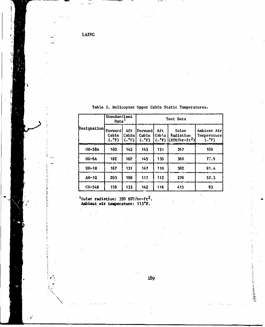
Table 2 presents cabin static temperatures at two upper cabin Iocatiorms for eachof the hellcopters tested, These data were gatherd at Edwards Air Force Base,Califorisa whites is located in the western M*oave high desert at an elevaticm of2300 feet. Bewuse of the altitude, the solar radiation at Edwards is about50 BTU/hr-ft2 higher and the ambient air temperature about 10'F lower than theconrspuAding value obtained at sea *We westen desert aea The cabin temperaturs
j,18-
LAING
Table 2. Helicopter Upper Cabin Static Temperatures.
Standardized Test Data
DataT
Desigiation Forward Aft Forward Aft Solar Avbient Air
Cabin Cabin Cabin Cabin Radiation Temperature-;(_*F) (-OP) (-OF) (-'F) (BTIJ/hr-ft2): (Wn
I0-58A 160 145 145 131 367 100
""ORt-6A 182 168 145 130 369 77.9
U1l1-IlR 167 131 147 110 382 91.4
All-IQ 203 198 117 112 278 52.3
Cii-54fl 158 133 142 116 415 93
'Solar radistlon: 350 MTh/hr-ft 2
A. i Amb ler t•emeratut: 113'F.
S..e9

r I
LAING
are standardized to a solar radiation of 350 BTU/hr-ft 2 and an ambient air temperatureof I13'F. Data were standardized to 350 BTU/hr-ft 2 and 1 130F, since militaryspecification MIL-STD-810B (ref 10) specifies these values for the conduct of testchamber solar radiation testing. The average of the forward and aft upper cabintemperatures is plotted versus the transparent area to cabin volume ratio in figure 11.The strong dependence of ,.abin static temperature on the area-to-volume ratio is clearlyshown. The curve in figure I I is empirically described by equation 6. This equationmay be used to predict the approximate maximum static temperatures for aircraft andprovide temparature environment design information for equipment located in the cabinarea.
Tss = 1722A/V + 143.5, for A/V , 0.6 (6)
All testing was conducted with an average wind speed of 5 knots or less. Windcaused lower cabin temperatures due to increased heat conduction from the cabin surfaceto the atmosphere with increasing wind speed. Aircraft were tested with all cabin vents,windows, and doors closed and with those cabin vents, windows, and doors open which
A . could be left open with the aircraft parked unattended. Test results with the cabini' • open were strongly dependent on the wind speed. There was little or no difference
in cabin temperatures between open and closed conditions with no wind and an
increasing difference in temperatures with increasing wind speed. For an average windspeed of 5 knots, the only aircraft which showed a significant drop in cabin temperature"with the cabin open was the UH-IH. A temperature drop of 7*F was recorded withthe vents and windows open and 32TF with the vents, windows, and doors open. Onall other aircraft tested, doors and windows could not be secured in a sufficieodtly openposition to provide enough ventilation to redune cabin temperatures. Opening of cabinvents was ineffective. Aircraft cabin heat transfer coefficients should be calculated onlyfor closed cabin conditions.
The majority of United States Army avionics equipment is qualified to a continuous-S xopc;rati'g temperature range of -65'F to 131'F, an intermittent operating temperature
range to 160TF, and a nonoperating temperature range of -80*F to 185F (ref 11). Noq,wification is requited for the transient condition which occurs when an aircraft cabintei.-ierature is staticaily above the intermittcat operating temperature limit, the aircraftcabin is open, and the aircraft immediately flown. This transient condition may causeawvimics and equipmcnt. failures during the time required for cabin and equipmenttemperatures to cool to operating limits. Equipment should be tested for operationat the tamnsient tempetures encountered when an aircraft goes from static to operating
Sconditions. The data for the AH-IG helicopter indicate that the maximum nonoperatingequipmnnt temperature should be extended from 185*F to 203TF.
This test method has also been used for othe•r enclosed areas of the aircraft whereno transparent area Is present and found to be valid. Although it has not been usedfor the measurement of surface temperatures, it should produce valid results. Statictemperature information for many locations in each of the aircraft tested Is presentedIn references 1 through S.
190
t /,Ii 4i

LAING
CONCLUSIONS
This paper has described a new test method for the measurement of aircraft cabin
static temperatures and has presented static temperature measurement data for thecurrent generation of Army helicopters. It has been shown that:
I. Extreme values of so!ar radiation and ambient air temperature are notnecessary to determine an aircraft static temperature environment. The test methodpresented in this paper allows measurement of static temperatures at the prevailingconditions and calculation of the aircraft static temperatuirs at the desired conditions.
2. The ratio of aircraft cabin transpamrnt area to cabin volume can be used topredict approximate aircraft cabin static temperatures.
3. Aircraft equipmer hbould be tested for ope-Ation at the transient temperaturesencountered when an aircrv t -:.as from static to operating conditions.
4. Maximum nonoperating equipment temperatures should be extended from185OF to 2030F.
REFERENCES
1. USAASTA Final Report No. 70-15-1, Instrument Panel and Avionics CompartmentEnvironmental Survey, Production OH-58A Helicopter, Laing, E. J., et al, US ArmyAviation Systems Test Activity, September 1972.
2. USAASTA Final Report No. 70-15-2, Vibration and Temperature Survey,Production UH-IH Helicopter, Laing, E. J., et al, US Army Aviation Systems TestActivity, January 1973.
3. USAASTA Final Report No. 70-15-3, Vibration and Temperature Survey, CH-54BHelicopter, Laing, E. J., et al, US Army Aviation Systems Test Activity, March 1973.
4. USAASTA Final Report No. 70-15-4, Vibration and Temperature Survey,Production OH-6A Helicopter, Laing, E. J., et al, US Army Aviation Systems TestActivity, June 1973.
5. USAASTA Final Report, No. 70-15-5, Vibration and Temperature Survey,Production AH-IG Helicopter, Laing, E. J., at &I, US Army Aviation Systems TestActivity, June 1974.
191N
- 2~

LAING
6. Publication, D2-905772-2, Atlas, R. A., and Charles, B. N., Summary of S&larRadiation Characteristics, Tabulir Summaries, December 1964.
7. Publication, Instut Royale Meteorologique de Belgique, Donnes du RayonnementSolaire a Leopoldville, Perlode 1953-1962, 1965.
8. Publication, Report No. 21, World Distribution of Solar Radiation,Lof, George 0. G., et al, Solar Energy Laboratory, Univemity of Wisconsin, July 1966.
9. USATC1OAM Final Report, No. 9-.O-005-030-006, Merhidology Investigallon ofJoint USAECOM/USATECOM Solar Radiation Test of Selected USAECOM Equipments,San Martin, R. L., US Army Test and Evaluation Command, March 1971.
10. Military Standard, MIL-STD-810B, Environmental Test Methods, 15 Junie 1967.
I1. Military Specification, MIL-E-5400N, Electronic Equipment, Airborne; GeneralSpecfifaton For, 30 November 1971.
1
4
-. .. i
i ¾,..