distributed busbar protection reb500 - abb group...distributed busbar protection reb500 • hmi menu...
TRANSCRIPT

png
Substation Automation Products
Distributed busbar protection REB500Application Manual


Document ID: 1MRK 505 349-UENIssued: March 2016
Revision: -Product version: 8.2
© Copyright 2016 ABB. All rights reserved
Copyright
This document and parts thereof must not be reproduced or copied without writtenpermission from ABB, and the contents thereof must not be imparted to a thirdparty, nor used for any unauthorized purpose.
The software and hardware described in this document is furnished under a licenseand may be used or disclosed only in accordance with the terms of such license.
Trademarks
ABB and Relion are registered trademarks of the ABB Group. All other brand orproduct names mentioned in this document may be trademarks or registered trade-marks of their respective holders.
Warranty
Please inquire about the terms of warranty from your nearest ABB representative.
ABB ABSubstation Automation ProductsSE-721 59 VästeråsSwedenTelephone: +46 (0) 21 32 50 00Facsimile: +46 (0) 21 14 69 18http://www.abb.com/substationautomation
Disclaimer
The data, examples and diagrams in this manual are included solely for the conceptor product description and are not to be deemed as a statement of guaranteed prop-erties. All persons responsible for applying the equipment addressed in this manualmust satisfy themselves that each intended application is suitable and acceptable,including that any applicable safety or other operational requirements are compliedwith. In particular, any risks in applications where a system failure and /or productfailure would create a risk for harm to property or persons (including but not lim-ited to personal injuries or death) shall be the sole responsibility of the person orentity applying the equipment, and those so responsible are hereby requested toensure that all measures are taken to exclude or mitigate such risks.
This document has been carefully checked by ABB but deviations cannot be com-pletely ruled out. In case any errors are detected, the reader is kindly requested tonotify the manufacturer. Other than under explicit contractual commitments, in noevent shall ABB be responsible or liable for any loss or damage resulting from theuse of this manual or the application of the equipment.
Conformity
This product complies with the directive of the Council of the European Communi-ties on the approximation of the laws of the Member States relating to electromag-netic compatibility (EMC Directive 2004/108/EC) and concerning electrical equip-ment for use within specified voltage limits (Low-voltage directive 2006/95/EC).This conformity is the result of tests conducted by ABB in accordance with theproduct standards EN 50263 and EN 60255-26 for the EMC directive, and with theproduct standards EN 60255-1 and EN 60255-27 for the low voltage directive. Theproduct is designed in accordance with the international standards of the IEC60255 series.

Safety information
Dangerous voltages can occur on the connectors, even though theauxiliary voltage has been disconnected.
Non-observance can result in death, personal injury or substantialproperty damage.
Only a competent electrician is allowed to carry out the electricalinstallation.
National and local electrical safety regulations must always be fol-lowed.
The frame of the IED has to be carefully earthed.
Whenever changes are made in the IED, measures should be takento avoid inadvertent tripping.
The IED contains components which are sensitive to electrostaticdischarge. Unnecessary touching of electronic components musttherefore be avoided.

Table of contents
Application Manual 1Distributed busbar protection REB500
Table of contents
Section 1 Introduction ................................................................. 51.1 This manual .................................................................................... 51.2 Intended audience .......................................................................... 51.3 Product documentation ................................................................... 51.4 Symbols and conventions ............................................................... 61.4.1 Symbols ..................................................................................... 61.4.2 Document conventions ............................................................... 6
Section 2 Overview .................................................................... 82.1 Application ...................................................................................... 82.2 System capacity .............................................................................. 9
Section 3 Software ................................................................... 123.1 System software REBSYS ............................................................ 123.2 Customer’s database .................................................................... 123.3 Human/machine interface program HMI500 .................................. 123.4 Local human/machine interface (local HMI) ................................... 123.5 Station monitoring system (SMS) .................................................. 133.6 Station automation system (SAS) .................................................. 13
Section 4 Signal acquisition and processing............................... 144.1 Analog inputs ................................................................................ 144.2 Maximum prolongation principle .................................................... 144.3 Binary inputs ................................................................................. 154.4 Binary outputs ............................................................................... 17
Section 5 Self-supervision ........................................................ 185.1 Diagnostic program ....................................................................... 185.2 Self-supervision system ................................................................ 195.2.1 Software supervision ................................................................ 195.2.2 Hardware supervision .............................................................. 215.2.3 Plausibility check...................................................................... 225.2.4 Internal analogue measurement supervision ............................ 23
Section 6 System Settings ........................................................ 256.1 Intertripping/transfer tripping.......................................................... 25
Table of contents
2 Application ManualDistributed busbar protection REB500
6.1.1 Busbar image ...........................................................................256.2 Isolator and circuit-breaker positions ..............................................276.2.1 Supervising isolator and circuit-breaker statuses .......................276.2.2 Auxiliary contacts ......................................................................286.2.3 Evaluating the isolator and circuit-breaker statuses ...................286.2.4 Isolator alarm ............................................................................296.2.5 Delay ........................................................................................296.2.6 Blocking by the isolator alarm....................................................296.2.7 Switch inhibit .............................................................................296.2.8 Acknowledging the isolator alarm ..............................................306.2.9 Note on isolators and circuit-breakers .......................................316.2.10 Response in the event of bay unit failure ...................................316.3 Bay unit stand-alone mode.............................................................316.3.1 Emergency bay unit operation ...................................................326.4 Enabling the tripping command ......................................................32
Section 7 Busbar protection ...................................................... 337.1 Protection zones ............................................................................337.2 Measuring principle ........................................................................337.2.1 Application example ..................................................................357.2.2 Safety aspects of the measuring principle .................................377.3 Restrained amplitude comparison ..................................................387.3.1 Amplitude comparison...............................................................387.3.2 Restraint current .......................................................................387.3.3 Operating characteristic ............................................................407.4 Restrained amplitude comparison with CT saturation .....................417.4.1 Application example ..................................................................417.5 Phase comparison .........................................................................437.6 Case studies: busbar layouts .........................................................447.6.1 Busbar with just two bays ..........................................................447.6.2 Busbar with several bays ..........................................................447.6.3 Busbar fault with through current ...............................................467.7 Differential current supervision .......................................................48
Section 8 Special applications of BBP ....................................... 498.1 Neutral current measurement .........................................................498.2 Blocking measurement of certain CTs ............................................52

Table of contents
Application Manual 3Distributed busbar protection REB500
8.2.1 Bus-tie breaker functions.......................................................... 538.2.2 Feeder circuit-breakers ............................................................ 578.2.3 Breaker reclaim time ................................................................ 588.2.4 “CB CLOSE” command (manual close signal) .......................... 608.3 Check zone protection for release of BBP ..................................... 618.3.1 Protection zones ...................................................................... 618.3.2 Measurement principle ............................................................. 618.3.3 Check zone .............................................................................. 648.3.4 Application of check zone protection ........................................ 658.3.5 Substation configuration ........................................................... 658.3.6 Maintenance conditions in connection with CzBBP ................... 66
Section 9 Breaker failure protection (BFP) ................................. 679.1 Current setting .............................................................................. 679.1.1 Iron core transformers (Class TPX) and transformers with residual
flux “air gap” (Class TPY) ......................................................... 679.1.2 Linearized current transformers (TPZ) ...................................... 689.2 Time-grading a single or two-stage BFP ........................................ 699.2.1 Case 1: Tripping by main protection successful ........................ 699.2.2 Case 2: Backup trip by BFP ..................................................... 709.2.3 Case 3: Intertripping of surrounding circuit-breakers by BFP .... 719.2.4 Timer t1 setting ........................................................................ 71
9.2.5 Timer t2 setting ........................................................................ 72
9.2.6 Maximum time t1max for backup tripping ................................. 72
9.2.7 Maximum time t2max for intertripping ....................................... 72
9.3 Logic type ..................................................................................... 739.4 BFP L0 system ............................................................................. 739.4.1 Current setting BFP L0 ............................................................. 739.4.2 Time grading for BFP L0 system .............................................. 779.5 External start of BFP ..................................................................... 779.6 BFP setting “Active for CB open” ................................................... 77
Section 10 Additional protection features ..................................... 7810.1 Enabling tripping commands ......................................................... 7810.1.1 Example 1: BBP function tripping enabled by external
undervoltage relay ................................................................... 78

Table of contents
4 Application ManualDistributed busbar protection REB500
10.1.2 Example 2: EFP function tripping enabled by the internalundervoltage function ................................................................79
10.1.3 Example 3: BBP tripping enabled by the internal undervoltagefunction .....................................................................................81
10.1.4 Example 4: BBP function tripping enabled by the internalundervoltage function without VTs on the busbars .....................82
10.1.5 Example 5: BBP neutral measuring system enabled by theinternal undervoltage function ...................................................83
Section 11 1½ breaker schemes and duplex stations ................... 8511.1 1½ breaker scheme with 3 CTs per diameter .................................8711.1.1 T zone protection with isolator Q6 closed ..................................8711.1.2 T zone protection with isolator Q6 open ....................................8711.2 1½ breaker scheme with 6 CTs per diameter .................................8811.3 1½ breaker scheme with 5 CTs per diameter .................................8911.4 1½ breaker scheme with 8 CTs per diameter .................................9011.5 1½ breaker scheme with only BBP function ....................................9011.6 Duplex station ................................................................................9111.7 Assignment of bay units .................................................................92
Section 12 Complex stations ...................................................... 9412.1 BBP and BFP in stations with a bypass busbar ..............................9412.2 Busbars with “bus-ties” in series .....................................................9412.3 Switchgear bays as bus-tie or feeder circuit-breaker.......................9812.4 Control using “11105_External TRIP” .............................................9912.4.1 1½ breaker scheme ..................................................................9912.4.2 Bypass mode ............................................................................9912.4.3 Bypass isolator .......................................................................100

1MRK 505 349-UEN Section 1Introduction
Application Manual 5Distributed busbar protection REB500
Section 1 Introduction
1.1 This manual
The application manual contains application descriptions and setting guidelines forthe REB500. The manual can be used to find out when and for what purpose a typi-cal protection function can be used. The manual can also be used when calculatingsettings.
1.2 Intended audience
This manual addresses the protection and control engineer responsible for plan-ning, pre-engineering and engineering.
The protection and control engineer must be experienced in electrical power engi-neering and have knowledge of related technology, such as protection schemes andcommunication principles.
1.3 Product documentation
Manual Document numberProduct Guide 1MRK 505 352-BEN
Application Manual 1MRK 505 349-UEN
Technical Manual 1MRK 505 350-UEN
Operation Manual 1MRK 500 124-UEN
Commissioning Manual 1MRK 505 351-UEN
Application ManualBay protection Functions
1MRK 505 353-UEN
Cyber Security Guideline 1MRK 511 373-UEN
Communication Protocol ManualIEC 61850
1MRK 511 370-UEN
Communication Protocol ManualIEC 60870-5-103
1MRK 511 371-UEN

Section 1 1MRK 505 349-UENIntroduction
6 Application ManualDistributed busbar protection REB500
1.4 Symbols and conventions
1.4.1 Symbols
The electrical warning icon indicates the presence of a hazard whichcould result in electrical shock.
The warning icon indicates the presence of a hazard which couldresult in personal injury.
The caution icon indicates important information or warning relatedto the concept discussed in the text. It might indicate the presence ofa hazard which could result in corruption of software or damage toequipment or property.
The information icon alerts the reader of important facts and condi-tions.
The tip icon indicates advice on, for example, how to design yourproject or how to use a certain function.
Although warning hazards are related to personal injury, it is necessary to under-stand that under certain operational conditions, operation of damaged equipmentmay result in degraded process performance leading to personal injury or death.Therefore, comply fully with all warning and caution notices.
1.4.2 Document conventions
A particular convention may not be used in this manual.
• Abbreviations and acronyms in this manual are spelled out in the glossary. Theglossary also contains definitions of important terms.
• Push button navigation in the LHMI menu structure is presented by using thepush button icons, e.g.:
To navigate the options, use and .

1MRK 505 349-UEN Section 1Introduction
Application Manual 7Distributed busbar protection REB500
• HMI menu paths are presented in bold, e.g.:Select Main menu/Settings.
• LHMI messages are shown in Courier font, e.g.:To save the changes in non-volatile memory, select Yes and ….
• Parameter names are shown in italics, e.g.:The function can be enabled and disabled with the Operation setting.
• The * character after an input or output signal name in the function block sym-bol given for a function indicates that the signal must be connected to anotherfunction block in the application configuration to achieve a valid applicationconfiguration.

Section 2 1MRK 505 349-UENOverview
8 Application ManualDistributed busbar protection REB500
Section 2 Overview
The digital busbar system REB500 belongs to the generation of fully digital protec-tion devices, i.e. the analog-to-digital conversion of the input variables takes placeimmediately after the input transformers and all further processing of the resultingdigital signals is performed by programmable microprocessors.
The main features which enable the REB500 to fully satisfy the demands placed ona modern protective device with respect to cost-effectiveness and functionality arecompact design, just a few different types of hardware units, modular software andcontinuous self-supervision and diagnosis.
The structure of the protection system is bay-oriented. The bay units may be lo-cated close to the switchgear in control and protection cubicles or in a central relayroom. Distributed bay units are connected to the central unit by an optical fiberprocess bus. The central unit collects all the data and executes the protection algo-rithms and auxiliary functions at station level.
The standard application of the protection system is that of busbar protection. Pro-vision is made, however for integrating optional functions to detect, for example,breaker failure, end zone faults, overcurrent and circuit-breaker pole discrepancy.
2.1 Application
The digital busbar protection has been designed for the high-speed selective protec-tion of MV, HV and EHV busbars in 50 and 60 Hz power systems. Because of theflexible and modular structure of both hardware and software, the protection can besimply configured to suit the particular busbar arrangement.
It is thus able to protect all busbar layouts, whether a single set of busbars or quad-ruple busbars with a transfer busbar. It is similarly applicable to ring busbars and1½ breaker schemes. The maximum capacity for a quadruple busbar system is 60feeders (60 bay units) with a maximum of 7 longitudinal breakers, 8 sections ofbusbars and 32 protection zones.
The protection system detects phase and ground faults in solidly grounded and im-pedance grounded power systems. The digital scheme only evaluates the primarysystem currents. The main CTs do not have to fulfill any special requirements as isthe case, for example, with a high-impedance scheme. Even in the event of satura-tion of the main CTs, the protection is still able to discriminate correctly betweeninternal and external faults.
1MRK 505 349-UEN Section 2Overview
Application Manual 9Distributed busbar protection REB500
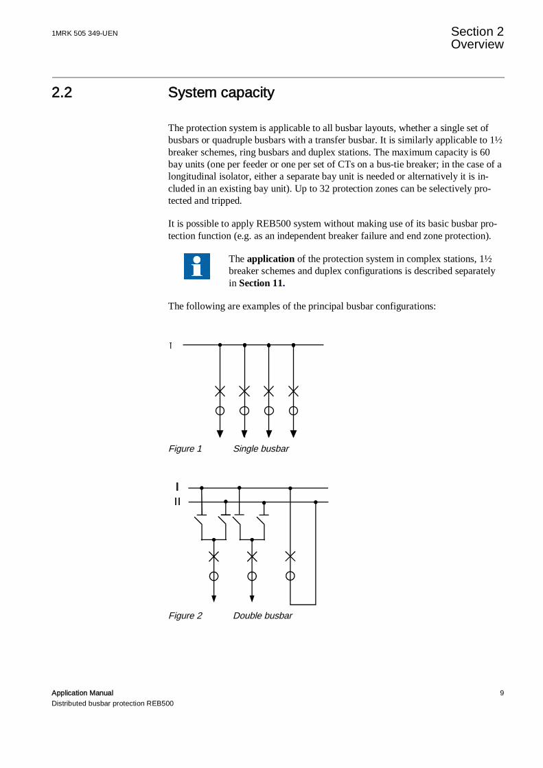
2.2 System capacity
The protection system is applicable to all busbar layouts, whether a single set ofbusbars or quadruple busbars with a transfer busbar. It is similarly applicable to 1½breaker schemes, ring busbars and duplex stations. The maximum capacity is 60bay units (one per feeder or one per set of CTs on a bus-tie breaker; in the case of alongitudinal isolator, either a separate bay unit is needed or alternatively it is in-cluded in an existing bay unit). Up to 32 protection zones can be selectively pro-tected and tripped.
It is possible to apply REB500 system without making use of its basic busbar pro-tection function (e.g. as an independent breaker failure and end zone protection).
The application of the protection system in complex stations, 1½breaker schemes and duplex configurations is described separatelyin Section 11.
The following are examples of the principal busbar configurations:
Figure 1 Single busbar
Figure 2 Double busbar
Section 2 1MRK 505 349-UENOverview
10 Application ManualDistributed busbar protection REB500
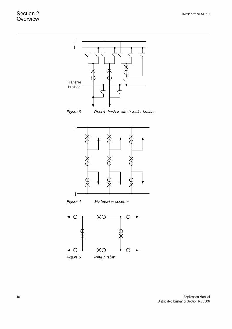
Figure 3 Double busbar with transfer busbar
Figure 4 1½ breaker scheme
Figure 5 Ring busbar
III
Transferbusbar

1MRK 505 349-UEN Section 2Overview
Application Manual 11Distributed busbar protection REB500
Figure 6 Duplex station
II
I

Section 3 1MRK 505 349-UENSoftware
12 Application ManualDistributed busbar protection REB500
Section 3 Software
3.1 System software REBSYS
This software package is installed on the system processor board. It includes all thesystem functions and also the local HMI (see Section 3.4 ) and the station monitor-ing system (see Section 5).
3.2 Customer’s database
The database was created according to the customer’s specification. It is installedon the master CPU in the central unit and for the most part can be edited usingHMI500.
3.3 Human/machine interface program HMI500
The human/machine interface (=HMI) program HMI500 provides convenient com-munication with the protection system to
• view measurements and statuses• set the protection functions• configure the system• commission and maintain the system• download data to the system• control the integrated disturbance recorder• control the integrated event recorder
3.4 Local human/machine interface (local HMI)
The local HMI program forms an integral part of the system software REBSYS.
Accessed via the control unit on the central unit or a bay unit, the local HMI soft-ware enables the following to be viewed, but for safety reasons not changed:
• current and voltage measurements• statuses of inputs and outputs• alarms
1MRK 505 349-UEN Section 3Software
Application Manual 13Distributed busbar protection REB500
• system settings• settings of the protection functions installed
3.5 Station monitoring system (SMS)
The REB500 system can be integrated in a station monitoring system (SMS). Referto the description of the station monitoring system (SMS) for further details.
3.6 Station automation system (SAS)
The REB500 system can be integrated in a station automation system (SAS). Referto the description of the station automation system (SAS) for further details.
Section 4 1MRK 505 349-UENSignal acquisition and processing
14 Application ManualDistributed busbar protection REB500
Section 4 Signal acquisition and processing
4.1 Analog inputs
The protection system processes the current measurements digitally in the bayunits. For this purpose, 80 measurements a period are made of the busbar feeders’currents. At a power system frequency of 50 Hz, this corresponds to a samplingrate of 4.0 kHz and at 60 Hz of 4.8 kHz. The analog/digital converter has a range of16 Bit.
Should a CT saturate, the signals are compensated by signal processing accordingto the maximum prolongation principle (see below). The signals then pass througha Fourier filter, which separates the real and imaginary fundamental frequencycomponents. All the other harmonics are suppressed.
These components are evaluated by all the protection functions in the bay unit. Thedisturbance recorder monitors the original non-compensated secondary current sig-nals. The current signals are also transferred to the central unit, which executes thebusbar protection function.
The optionally available voltages are measured essentially the same as currentswith the exception that maximum prolongation is not applied.
4.2 Maximum prolongation principle
The maximum prolongation principle is a method patented by the manufacturer foradditionally processing the current signals to enable the protection algorithms todetect faults discriminatively even if CTs are saturating.
Basically it uses the maximum value detected in the sampling window should a CTsaturate.
By prolonging the maximum value, the signal is compensated suchthat the best possible approximation of the phase-angle and ampli-tude of the unsaturated signal is achieved.

1MRK 505 349-UEN Section 4Signal acquisition and processing
Application Manual 15Distributed busbar protection REB500
Figure 7 Maximum prolongation principle in the case of CT
Time t0 is the interval between the last zero crossing before the maximum value isdetected and the end of the prolongation period. At a power system frequency of50 Hz, this time is 12.5 ms (at 60 Hz, 10.4 ms). The rise time from the zero cross-ing to the maximum value is defined as ta. The difference between to and ta is timeth, which is then the time the maximum value in the sampling window is prolonged.The longer time ta, the shorter the maximum value is prolonged.
Consider the following example:
High through-fault currents can cause one or more CTs to saturate and could giverise to a false differential current, which, if no precautions were taken, might beinterpreted as an internal fault. The maximum prolongation function maintains pro-tection stability and discrimination in the presence of CT saturation, because thesignals transferred are a good approximation of the phase-angle and amplitude ofthe unsaturated signals (see Section 7. “Busbar protection”).
4.3 Binary inputs
Optocouplers electrically insulate all the binary inputs.
They pick up when the input voltage remains above 80% of the rated auxiliaryvoltage for at least 20 ms and reset when it is below 65% for longer than 20 ms.

Section 4 1MRK 505 349-UENSignal acquisition and processing
16 Application ManualDistributed busbar protection REB500
The standard binary inputs are all equipped with anti-bounce filters. The softwareanti-bounce filter has no influence on a signal’s time stamp, i.e. the time stamp isdetermined by the first occurrence of the signal at the input of the optocoupler.
Figure 8 Anti-bounce filter
The anti-bounce time for the special signals below is set to the minimum of 2 msinstead of the standard time (normally 20 ms) set generally for the system:
• All disturbance recorder input signals “167nn_Start DR_x” and “36705_Gen-eral Start DR”
• Breaker failure input signals “137nn_Start BFP_Lx”,“13705_External StartBFP” and “138nn_Start BFP Q0 no I_x”
• “31805_External release BB zone” and “11605_External release Trip”• The signals “11510…11525_Supervison aux. voltage_x” are set to a fixed
anti-bounce time of 10 ms.
Should several signals be configured for a common optocoupler in-put and one of them have a minimum anti-bounce time of 2 ms,then 2 ms applies for all the signals. This kind of configurationshould be avoided wherever possible.
Due to system constraints the trigger for the disturbance recordercan be delayed by a maximum of one base-period.
A distinction is made between input signals with a slow response and those with afast response. Internally, REB500 processes the process bus signals in fast andslow cycles according to their priority.
Table 1 Signal response timesSignal response Descriptionslow These signals must be maintained at the binary input for at least 50 ms plus the
anti-bounce time and are processed by the slow cycle.fast These signals must be maintained at the binary input for at least 6 ms plus the
anti-bounce time and are processed by the fast cycle.
Time stamp
Anti- bouncefilter time
Opto-coupler input signal
Internal REB500 signal afterthe anti-bounce filter
1MRK 505 349-UEN Section 4Signal acquisition and processing
Application Manual 17Distributed busbar protection REB500
4.4 Binary outputs
The bay units generate two kinds of binary output signals, tripping commands andlogic signals. The central unit only generates logic signals.
Binary output signals are generated by the processors in the central and bay units asdetermined by signal logics.
Tripping commands are written in capital letters to distinguish themfrom logic signals.
Output signals can be assigned to auxiliary output relays to actuate either a trippingor signaling circuit. As a safety precaution, it is impossible to assign tripping com-mands and logic signals to the same output relay, i.e. tripping commands can onlybe combined with other tripping commands and logic signals with other logic sig-nals. For example, the signals “21305_Trip” and “21105_EXTERNAL TRIP” can-not be configured to operate the same output contact.
Section 5 1MRK 505 349-UENSelf-supervision
18 Application ManualDistributed busbar protection REB500
Section 5 Self-supervision
To ensure the maximum possible reliability, the REB500 is equipped with a self-supervision function, which enables it to respond quickly to any hardware (HW) orsoftware (SW) errors. Some, such as an error in transmission via the process bus,only affect a single data set and are generally of a transient nature. A serious errorwould mean, for example, that reliable operation could no longer be guaranteed. Itis important to detect errors of this kind and to take the appropriate action, whichcan include blocking the protection functions and tripping outputs.
The self-supervision and diagnostic function ensures the high availability of thebusbar protection. Errors and defects are immediately detected and signaled so thatcorrective action can be taken without delay.
The self-supervision software forms part of the REBSYS system software (see Sec-tion 3.1).
5.1 Diagnostic program
The task of the diagnostic program is to manage (start and stop) all the other appli-cations (e.g. protection functions and binary inputs and outputs) and process thedata of the self-supervision function.
The system SW is divided into sub-systems that perform specific applications (pro-tection functions, binary inputs and outputs, database controller etc.). The structureof the diagnostic program reflects the structure and distributed architecture of theprotection system, i.e. it is also distributed between every module of the centralunit and bay units having a microprocessor.
Each level in the structure of the diagnostic program reports the status of the appli-cations at the same or lower levels to the next level up. Enabling (release) signalsare distributed from top to bottom. As soon as the diagnostic program detects acritical fault, it reports the corresponding status upwards and blocks the downwardsdistribution of the enabling signal. The protection system thus propagates theblocking of the enabling signal to block all tripping outputs. In the case of criticalfaults, the protection system is shut down and restarted.

1MRK 505 349-UEN Section 5Self-supervision
Application Manual 19Distributed busbar protection REB500
5.2 Self-supervision system
The self-supervision system covers software and hardware and includes in additionto the internal signals the monitoring of the external input values such as currentvalues (CT supervision) and the positions of the auxiliary contacts on isolators andcircuit-breakers (busbar replica).
Figure 9 Structure of the self-supervision system
The different layers of the self-supervision system displayed in Figure 9 are de-scribed in further detail in the following sections:
1. Section 5.2.12. Section 5.2.23. Section 5.2.34. Section 5.2.45. Section 6.2.16. Section 7.7
5.2.1 Software supervision
5.2.1.1 Supervising the applications
The diagnostic program can control applications by detecting status changes (e.g.initialization and stopping at the right instant). The applications report their statuses
Section 5 1MRK 505 349-UENSelf-supervision
20 Application ManualDistributed busbar protection REB500
(e.g. initialization finished, processing finished or error detected). Using statuschanges to supervise the applications means that an application that has beenstarted must report back to the diagnostic program within a given time.
A hard-wired watchdog per microprocessor which the programs have to reset atregular intervals supervises the entire SW. Should a watchdog not be reset, thewatchdog timer times out and initiates a hardware reset.
5.2.1.2 Supervision of data transfer via the process bus
A number of supervised criteria ensure the integrity of the data transferred via theprocess bus. All data transferred via the process bus are subject to cyclic redun-dancy checks as part of the Ethernet transmission.
5.2.1.3 Supervision of the protection functions
The operation of every application is synchronized and a time stamp is attached toall analog signal samples and binary signals. Before determining a differential cur-rent, a check is performed to make sure the samples have the same time stamp.Should this not be the case, the samples concerned are not evaluated.
5.2.1.4 Processing and supervising the binary inputs
Every binary input is equipped with its own anti-bounce software. As a rule, thestatus of a signal is considered valid for processing if it persists 20 ms after its firstincidence.
The binary inputs are also supervised with respect to oscillations. If the status of aninput changes five times in 100 ms, the input is marked as “invalid”. In this case,the signal is processed such that the reliability of the system is assured, i.e. invalidblocking inputs are assumed to be active.
5.2.1.5 Enabling binary outputs
To achieve the maximum reliability of the system, every tripping command has anassociated enabling signal and should the diagnostics program detect an HW or SWerror, it suppresses the enabling signals for the binary outputs, i.e. the tripping out-puts are inhibited.
5.2.1.6 Error messages in the event list
All errors and defects detected by the self-supervision function are processed bythe diagnostics program and recorded as events. These are classified as “major er-rors” if the proper operation of the protection functions can no longer be guaran-teed.

1MRK 505 349-UEN Section 5Self-supervision
Application Manual 21Distributed busbar protection REB500
In such cases, the system is automatically restarted. All the output channels areblocked, the protection devices are no longer standing by and the green LEDs onthe local control units flash.
Errors that do not endanger the proper operation of the protection functions areclassified as “minor errors”.
5.2.1.7 Starting or restarting the system
When the self-supervision function or the diagnostics program restarts the systemor a part of it, the procedure is signaled on the local control unit. The blocked statusof the system is signaled by the flashing yellow LED on all the units and on theHMI.
While the system is starting, all the LEDs flash and the SW applications are indi-cated by a designation (e.g. MPL, TIM etc.). The successful start-up of the systemcan be seen from the fact that the main menu is displayed on all the units and thatthe signal “41810_In service” is set.
5.2.2 Hardware supervision
5.2.2.1 Supervising the auxiliary supply
The power supply units in the central and bay units are supervised with respect totheir permissible variations. An auxiliary supply voltage that is out of tolerancecounts as a major error, i.e. the protection system is shut down and restarted.
5.2.2.2 Microprocessor program and main memories
All main memories are tested by writing and then reading a test pattern.
5.2.2.3 Supervision of the tripping relay coils
Each of the tripping relays in a bay unit is fitted with a circuit for supervising theintegrity of the tripping relay coil.
5.2.2.4 Parts not covered by the self-supervision function
It is impossible to supervise all parts of the protection chain, e.g. the binary inputcircuits. It is also advisable to install an external trip circuit supervision system.

Section 5 1MRK 505 349-UENSelf-supervision
22 Application ManualDistributed busbar protection REB500
5.2.3 Plausibility check
As was described in Section 5.2.2, all analog inputs of all the bay units are super-vised. If such supervision detects a discrepancy, it blocks the respective bay unit.This is performed locally and is complemented by a plausibility check carried outby the central unit on the entire system which includes all the zones of the busbarprotection (BBP) application. This involves evaluating the current changes takingplace in all the bay units. The plausibility check is based on the fact that a changeof current (amplitude) caused by a busbar fault must be present in at least two bayunits of a busbar zone. (see Figure 10).
Figure 10 Plausibility check releases BBP-TRIP
The busbar protection is not permitted to trip if this condition is not fulfilled.
Figure 11 Plausibility check blocks BBP-TRIP
There are situations and operating conditions in which the plausibility check is by-passed, i.e. it bears no influence on the tripping decision by the busbar protection.
Such situations and operating conditions are:
• The protection zone comprises only a single bay unit, or all other bay units ofthis protection zone are not conducting any current (current below 0.075 x In)(see Figure 12).

1MRK 505 349-UEN Section 5Self-supervision
Application Manual 23Distributed busbar protection REB500
Figure 12 Plausibility check is bypassed (no influence to BBP-TRIP)
• Approx. 400 ms after the number of current measurements assigned to a pro-tection zone has changed (change of breaker/ isolator position or blocking ofcoupler measurement, see Section 8.2.1.2).
• As long as REB500/REB500sys system is in the ”Test mode”
When testing a system by injecting currents, the plausibility checkhas no influence to the test providing a busbar protection zone onlyhas a single bay unit connected to it. However, if more than one bayunit is connected to a zone, REB500 should be switched to the “Testmode” for the duration of the test. The plausibility check then can-not falsify the test results.
5.2.4 Internal analogue measurement supervision
The correct operation of the analogue inputs and the analog to digital (A/D) con-verters is supervised by the internal comparison of ‘IL1+IL2+IL3= - IL0’.
Per default the internal analogue measurement supervision is acti-vated. The status of this supervision can be changed while engineer-ing the system, or under the “Configurator mode” of HMI500.
It is recommended not to change the default activation state of theinternal analogue measurement supervision.
5.2.4.1 Wiring of the analogue inputs
The external wiring shown in the diagram below is mandatory for the internal ana-logue measurement supervision.

Section 5 1MRK 505 349-UENSelf-supervision
24 Application ManualDistributed busbar protection REB500
Figure 13 External wiring mandatory for the analogue measurement supervision
Core-balance CT’s must not be used for IL0, if the supervision is ac-tivated. The main current transformers of L1, L2 and L3 shall havethe same current ratio and under the HMI menu “current trans-former” the settings for “I1,I2,I3” and “I4” shall be identical.
This is not a CT supervision, because the internal analogue supervi-sion does not check the relation between phases. For details aboutCT supervision see Section 7.7 “Differential current supervision”.
5.2.4.2 Secondary injection tests
If currents are injected for test purposes on a single phase, e.g. during commission-ing, the external wiring must include the neutral path (IL0). If not, the analoguemeasurement supervision will block the protection algorithm.
When testing a system by injecting currents, the internal analoguemeasurement supervision can be deactivated by switching theREB500 to the “Test mode”. The internal analogue measurementsupervision then cannot falsify the test results. The wiring of theneutral path (IL0) is not necessary for this mode.
1MRK 505 349-UEN Section 6System Settings
Application Manual 25Distributed busbar protection REB500
Section 6 System Settings
6.1 Intertripping/transfer tripping
The intertripping system establishes an image of the busbar configuration and per-forms essentially two tasks:
1. The assignment of analog measurements to the protection zones of the busbarprotection function (assignment is refreshed every 6 ms, i.e. fast part, fast sig-nal)
2. Determines the tripping logic according to protection zones for the protectionfunctions
• busbar protection (the zone containing the fault)• end zone protection (zone with the end zone fault)• breaker failure protection (zone with the defective circuit-breaker)• enabling tripping (external enabling signal, low-voltage check feature)• intertripping
As an example consider a fault on busbar 1 of double busbars (see Figure 2).
1. Only those feeders connected to busbar 1 are assigned to the measuring systemof busbar 1. The assignment of the feeders is carried out by the intertrippingsystem, which evaluates the positions of the isolators.
2. The measuring system on busbar 1 detects the internal fault and issues a trip-ping command for busbar 1 to the intertripping system.
The intertripping system knows from the positions of the isolators, which feed-ers are connected to busbar 1 and the tripping command to the circuit-breakersof all those feeders with isolators closed onto busbar 1.
It is thus extremely important for the correct isolator positions to be reported to theprotection system.
The intertripping system also detects when protection zones are connected together(e.g. both feeder isolators closed).
6.1.1 Busbar image
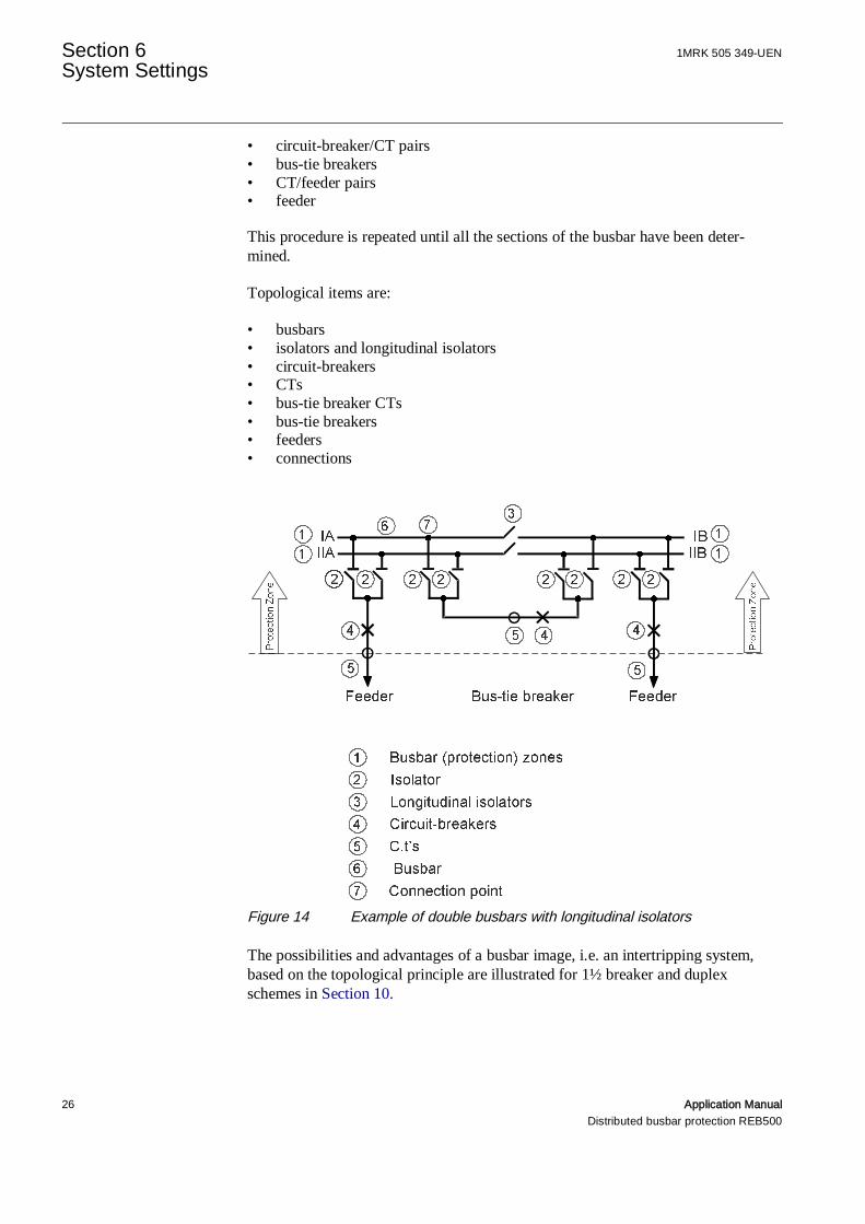
The busbar image is based on a topological principle, i.e. it only includes topologi-cal items that are necessary from the point of view of protection. It starts with abusbar section and checks all its electrical connections and constructs a protectionzone bounded by the following items:
Section 6 1MRK 505 349-UENSystem Settings
26 Application ManualDistributed busbar protection REB500
• circuit-breaker/CT pairs• bus-tie breakers• CT/feeder pairs• feeder
This procedure is repeated until all the sections of the busbar have been deter-mined.
Topological items are:
• busbars• isolators and longitudinal isolators• circuit-breakers• CTs• bus-tie breaker CTs• bus-tie breakers• feeders• connections
Figure 14 Example of double busbars with longitudinal isolators
The possibilities and advantages of a busbar image, i.e. an intertripping system,based on the topological principle are illustrated for 1½ breaker and duplexschemes in Section 10.

1MRK 505 349-UEN Section 6System Settings
Application Manual 27Distributed busbar protection REB500
6.2 Isolator and circuit-breaker positions
In addition to correct isolator positions, it is also necessary to know the statuses ofthe circuit-breakers that have been configured. The statuses (positions) of the cir-cuit-breakers can influence the following protection functions:
1. Busbar protection (see Section 7.)2. End zone protection:
The end zone protection function is blocked when the circuit-breaker is closed.Should signals be incorrectly wired such that an “open” signal is generatedwhen the circuit-breaker is in fact closed, there is a likelihood of mal-operationin the event of a fault on the power system.
Where CB positions signals are configured as inputs, it is extremelyimportant for the “CB Close” command to be correctly connected(see Section 8.2.4., “CB CLOSE” command (manual close sig-nal)”).
The statuses of the auxiliary contacts on the isolators and circuit-breakers reflectthe statuses of the latter (CLOSED or OPEN). Each of these statuses is representedby an independent signal (one for CLOSED and one for OPEN).
The image of the isolators is refreshed every 50 ms and the one for the circuit-breakers every 6 ms.
Where during inspection or maintenance the statuses of isolators orcircuit-breakers are simulated either by a maintenance input or ex-ternal jumpers, the system will respond according to the simulatedstatuses of isolators and circuit-breakers.
Therefore take care when resorting to such manipulations!
6.2.1 Supervising isolator and circuit-breaker statuses
A supervision algorithm detects the presence of the auxiliary supply. To be cor-rect, it has to be measured at either one or the other, i.e. corresponding to CLOSEDor OPEN. An alarm is generated, if after a preset delay either both are missing orboth present.
The supervision algorithm detects the following faults in the isolator and circuit-breaker return confirmation circuits:

Section 6 1MRK 505 349-UENSystem Settings
28 Application ManualDistributed busbar protection REB500
• Failure of the auxiliary supply in the return confirmation circuits (e.g. trippedminiature circuit-breaker)
• Undefined status of the main isolator contacts (e.g. mechanical defect)• Wiring error• Undefined status due to incorrect simulation
The supervision system cannot detect exchanged “CLOSED” and“OPEN” signals. This condition may be detected by the differentialcurrent supervision function (see Section 7.7).
6.2.2 Auxiliary contacts
A potentially-free N/O and N/C contact must be provided for each isolator and cir-cuit-breaker. The N/O contact signals that the isolator or circuit-breaker is“CLOSED” and the N/C contact that it is “OPEN”.
The switching sequence and wiring are described in the Commis-sioning Manual.
6.2.3 Evaluating the isolator and circuit-breaker statuses
The isolator and circuit-breaker statuses are evaluated as follows:
Table 2 Evaluating isolator and circuit-breaker statusesReturn confirmation thatisolator/CB “CLOSED”
Return confirmation that iso-lator/CB “OPEN”
Isolator/CB image
inactive inactive Last status retained and delayedfor the bus image of busbar pro-tection- isolator alarm- switch inhibit signal
inactive active OPENactive inactive CLOSEDactive active CLOSED
and delayed- isolator alarm- switch inhibit signal
An active “CB CLOSE” signal (“CB CLOSE” command) forces the circuit-breakers into the“CLOSED” position.
1MRK 505 349-UEN Section 6System Settings
Application Manual 29Distributed busbar protection REB500
6.2.4 Isolator alarm
If the isolator and circuit-breaker supervision function detects an error, it is sig-naled on the local HMI and also via the output signal “Isolator alarm” after the setsignal delay.
6.2.5 Delay
Isolators require a certain time to operate and while they are in motion, the rela-tionship between the status signals and therefore the integrity of the isolator imagemay be briefly disturbed due to the different points at which the auxiliary contactsare actuated. As this is quite normal, an isolator alarm should not be generated andtherefore the alarm has to be delayed.
6.2.6 Blocking by the isolator alarm
If considered necessary, the isolator alarm can be arranged (set) to block the pro-tection. There are two alternative settings:
• Block protectionOperation of the busbar protection and the intertripping system is completelyblocked.
• Discriminative blocking (preferred alternative)Operation of the busbar protection and the intertripping system is only blockedfor the section of busbar (protection zone) concerned.
6.2.7 Switch inhibit
If the isolator alarm was initiated by an isolator or circuit-breaker that at the timedetermined the assignment of protection zones, the “Switch inhibit” signal is alsoset.
While the “Switch inhibit” signal is active, it is recommended toavoid operating isolators or circuit-breakers in the station. On noaccount is it permitted to operate an isolator or circuit-breakerin the bay from which the alarm originates. This is because thelast isolator status is retained in the bus image of busbar protection,which therefore would no longer correspond to the actual state ofthe station and would falsify the intertripping system.
A false differential current may result, which if the isolator alarm isnot configured to block the protection would cause mal-operation ofthe protection.

Section 6 1MRK 505 349-UENSystem Settings
30 Application ManualDistributed busbar protection REB500
The incorrect control of the intertripping logic means that in theevent of a fault the wrong circuit-breakers are tripped.
The “Switch inhibit” signal is not set, however, if the isolator or circuit-breakerconcerned does not determine the assignment of protection zones. Figure 15 showsan example for a bus-tie breaker. Isolators Q1, Q2, Q10 and Q20 are open andtherefore the bus-tie breaker Q0 is not assigned to a protection zone and of no con-sequence for the circuit-breaker image.
Figure 15 Circuit-breaker image of no consequence if the isolators are open
6.2.8 Acknowledging the isolator alarm
Figure 16 shows the responses of the signals in the event of an isolator alarm andswitch inhibit.
The isolator alarm is reset and the blocking of the protection cancelled by applyinga signal to the input “Accept bus image alarm”. The signal “Switch inhibit” staysactive.
If it is not acknowledged, the signal Isolator alarm is reset and blocking cancelledautomatically should the isolators and the circuit-breakers adopt correct statuses.
If the isolator alarm is set due to the failure of the auxiliary supplyfor the return confirmation circuit (e.g. MCB. trip or deliberatelyswitched off for maintenance), it may be acknowledged. Providingno switching operations are performed on the feeder, a hazardoussituation cannot arise because the last status is retained for busbarprotection.
If the isolator alarm is set due to an undefined status of the mainisolator contact (e.g. a mechanical defect), a wiring error or in-correct simulation, station operating guidelines must specifywhether the protection should be blocked (danger of failing to trip)or be reset (danger of mal-operation).

1MRK 505 349-UEN Section 6System Settings
Application Manual 31Distributed busbar protection REB500
Figure 16 Signal responses for an isolator alarm and switch inhibit
6.2.9 Note on isolators and circuit-breakers
Where the REB500 station image includes an isolator or a circuit-breaker and theisolator or circuit-breaker return confirmations are not configured as binary inputs,the respective switch is considered to be closed. This only applies to active (un-masked) bays.
6.2.10 Response in the event of bay unit failure
The response of the protection functions in the event of a bay unit failing dependson the status of the isolators.
If at the instant of failure all the isolators are open, i.e. the current is not assigned toa measuring unit, an isolator alarm is generated immediately and, depending on thesystem configuration, the protection zone is blocked (setting: everything blocked ordiscriminative blocking) or the busbar protection continues to operate (setting: re-main in operation).
If, on the other hand, one or several isolators are closed at the instant of the failure,i.e. the current is being measured, the protection zone concerned is immediatelyblocked and the signals “Isolator alarm” and “Switch inhibit” activated.
6.3 Bay unit stand-alone mode
In the event of a failure of the central unit or an optical fiber cable, a bay unit con-tinues to perform the local breaker failure, end fault and time overcurrent protec-tion and disturbance recorder functions. This, however, is an emergency mode sub-ject to limitations:

Section 6 1MRK 505 349-UENSystem Settings
32 Application ManualDistributed busbar protection REB500
• Since there is no communication with the central unit, intertripping is impossi-ble.
• Operation of HMI500 running on a PC connected to the bay unit and the localHMI is limited and they take longer to respond. Events, disturbance recorderrecords, the binary inputs and outputs and currents and voltages can beviewed.
6.3.1 Emergency bay unit operation
A bay unit can also start without the central unit in an emergency mode. The set-tings last used are retained. The local breaker failure, end fault and time overcur-rent protection and disturbance recorder functions are fully functional.
Blocking signals previously set by the central unit are maintained, but can be resetusing the local HMI.
In the emergency mode, the time is held at its value when a bay unit is switchedoff. Upon restarting in the emergency mode, the internal time resumes from thevalue it was held at.
When communication is re-established, a bay unit resumes normal operation with-out having to be restarted.
6.4 Enabling the tripping command
For special applications, tripping commands can be interlocked by enabling sig-nals.
1MRK 505 349-UEN Section 7Busbar protection
Application Manual 33Distributed busbar protection REB500
Section 7 Busbar protection
The busbar protection operates according to the differential protection principle. Itdetects and trips phase and earth faults in MV, HV and EHV power systems.
The main demands the busbar protection has to fulfill are:
• fast and discriminative isolation of the faulted section of busbar• high through-fault stability
The busbar protection algorithm is executed by the central unit.
Following pre-processing in the bay units (see Section 4.1), real and imaginarycomponents of the fundamental frequency are transferred to the central unit for fur-ther processing every 6 ms.
7.1 Protection zones
The busbar protection performs a separate measurement for each protection zoneand each phase. A section of busbar that in the event of an internal fault would betripped as a single unit (no further subdivision by a circuit-breaker possible) is de-fined as a protection zone.
The assignment of feeder currents to the individual protection zone measurementsis achieved with the aid of a busbar image in the intertripping system (see Section6.1).
7.2 Measuring principle
The busbar protection (BBP) operates according to the principle of a combined dif-ferential current measurement with operation and restraint features and a phasecomparison function. In a healthy condition and according to Kirchhoff’s first law,all the currents flowing towards a busbar section must leave it again.
The busbar protection scheme is based on a measurement algorithm, which com-pares the amplitudes of the feeder currents and derives a restraint criterion. The al-gorithm is executed independently for each protection zone and phase. In additionto amplitude comparison, their phase relationship is also compared as a second cri-terion (see Section 7.5 ”Phase comparison”.
Section 7 1MRK 505 349-UENBusbar protection
34 Application ManualDistributed busbar protection REB500
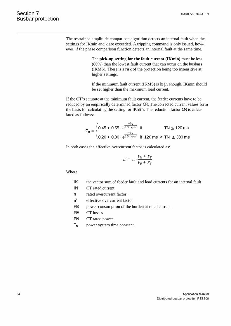
The restrained amplitude comparison algorithm detects an internal fault when thesettings for IKmin and k are exceeded. A tripping command is only issued, how-ever, if the phase comparison function detects an internal fault at the same time.
The pick-up setting for the fault current (IKmin) must be less(80%) than the lowest fault current that can occur on the busbars(IKMS). There is a risk of the protection being too insensitive athigher settings.
If the minimum fault current (IKMS) is high enough, IKmin shouldbe set higher than the maximum load current.
If the CT’s saturate at the minimum fault current, the feeder currents have to bereduced by an empirically determined factor CR. The corrected current values formthe basis for calculating the setting for IKmin. The reduction factor CR is calcu-lated as follows:
C =0.45 + 0.55 ⋅ e . ⋅ ⋅ if TN ≤ 120ms
0.20 + 0.80 ⋅ e . ⋅ ⋅ if120ms < TN ≤ 300ms
In both cases the effective overcurrent factor is calculated as:
′ = ∙++
Where
IK the vector sum of feeder fault and load currents for an internal faultIN CT rated currentn rated overcurrent factorn′ effective overcurrent factorPB power consumption of the burden at rated currentPE CT lossesPN CT rated powerT power system time constant

1MRK 505 349-UEN Section 7Busbar protection
Application Manual 35Distributed busbar protection REB500
7.2.1 Application example
The minimum busbar fault current is 1300 A and is supplied by two feeders. Thetime constant TN of the power system is 80 ms.
Parameter Feeder 1 Feeder 2Contribution to minimum fault current 800 A 500 ACTs Ratio 200 A / 1 A 400 A / 1 AClass 5P10 5P20P 6 VA 6 VAP 5 VA 8 VAP 10 VA 20 VA
n = 10 ⋅10VA+5VA6VA+5VA
= 13.6
n = 20 ⋅20VA+8VA6VA+8VA
= 40
C = 0.45 + 0.55 ⋅ eA
0.3⋅ A⋅ . ≈ 0.66
C = 0.45 + 0.55 ⋅ eA
0.3⋅ A⋅ ≈ 0.95
Reduced fault current I = 800A ⋅ 0.66 + 500A ⋅ 0.95 = 1003A.
IKmin setting (80% of I ): 802 A
The factor k is normally set to 0.80. Numerous tests on a network model haveshown this setting to be the most favorable.

Section 7 1MRK 505 349-UENBusbar protection
36 Application ManualDistributed busbar protection REB500
Figure 21 Operating characteristic of restrained amplitude comparison
During a through-fault and normal operation, it is impossible for thedifferential (operating) current to be higher than the restraintcurrent.
The neutral current has to be separately monitored in power systems with imped-ance grounding (optional) (see Section 8.1. “Neutral current measurement”).It isevaluated independently of the two conductor-sensitive protection functions.
The logical interlocking of the protection functions (Figure 17) shows that the pro-tection system can only trip when both protection functions (restrained amplitudeand phase comparisons) detect a fault on the same busbar section and phase.

1MRK 505 349-UEN Section 7Busbar protection
Application Manual 37Distributed busbar protection REB500
Figure 17 REB500 protection functions
7.2.2 Safety aspects of the measuring principle
High through-fault currents can drive one or more of the CTs into saturation.
The resulting distorted current signals give rise to a false differential current and anincorrect phase relationship between the currents. In extreme cases, an internalfault might be simulated if no precautions were taken.

Section 7 1MRK 505 349-UENBusbar protection
38 Application ManualDistributed busbar protection REB500
The preprocessing of the current signals in the bay units enables the protection al-gorithms to detect faults discriminatively in all cases (even in the presence of CTsaturation).
The maximum prolongation principle (see Section 4.13) achieves a very good ap-proximation with respect to the real and imaginary components (amplitude andphase-angle) of the original current signal.
7.3 Restrained amplitude comparison
The restrained amplitude comparison function is basically a differential currentmeasurement with the sum of all the current amplitudes acting in a re-straining sense.
7.3.1 Amplitude comparison
The differential current is the geometric sum of all the currents flowing to-wards and away from the busbar. It is calculated from the fundamental componentsof the currents conducted by the feeders and the bus-tie breakers:
= Re + ⋅ Im
7.3.2 Restraint current
The stability factor is derived from the restraint current which is the sum ofthe currents of the various feeders. The following is an example for the determina-tion of for phase Î{ 1, 2, 3}:
= Re + ⋅ Im

1MRK 505 349-UEN Section 7Busbar protection
Application Manual 39Distributed busbar protection REB500
The stability factor thus becomes:
= =∑ Re + ⋅ ∑ Im
∑ Re + ⋅ Im
where
stability factor per protection zone
fundamental component after the Fourier filter in phase of feeder
total number of feeders and bus-tie breakers per protection zone
The scheme detects an internal fault on the busbar when the stability factor ex-ceeds the setting (typically 0.80) and the differential current is greater thanthe setting for the restraint current . The differential current in normal opera-tion or during a through-fault is close to zero. By including the restraint current inthe denominator the range for the stability factor becomes 0£ £1.
Simplified examples for stability factor :
Figure 18 Through-fault
Applying the equation above to Figure 18 yields = | || | | | | | = 0.
Figure 19 Internal fault
Applying the equation above to Figure 19 yields = | || | | | | | = 1.

Section 7 1MRK 505 349-UENBusbar protection
40 Application ManualDistributed busbar protection REB500
Figure 20 Through-fault with CT saturation
Applying the equation above to Figure 20 yields = | || | | | | | = 0.67.
7.3.3 Operating characteristic
The following operating characteristic results:
Figure 21 Operating characteristic of the restrained differential current meas-urement in HMI500
The operating area is above the bold line.
1MRK 505 349-UEN Section 7Busbar protection
Application Manual 41Distributed busbar protection REB500
7.4 Restrained amplitude comparison with CTsaturation
The restrained amplitude comparison algorithm detects an internal fault when thesettings for IKmin and k are exceeded. A tripping command is only issued, however,if the phase comparison function detects an internal fault at the same time.
The pick-up setting for the fault current (IKmin) must be less(80%) than the lowest fault current that can occur on the busbars(IKMS). There is a risk of the protection being too insensitive athigher settings.
If the minimum fault current (IKMS) is high enough, IKmin should beset higher than the maximum load current.
If the CT’s saturate at the minimum fault current, the feeder currents have to bereduced by an empirically determined factor . The corrected current values formthe basis for calculating the setting for . The reduction factor is calculatedas follows:
=0.45 + 0.55 ⋅ . ⋅ ⋅ if ≤ 120ms
0.20 + 0.80 ⋅ . ⋅ ⋅ if120ms < ≤ 300ms
Where
the vector sum of feeder fault and load currents for an internal fault
CT rated current
rated overcurrent factor
′ effective overcurrent factor
power consumption of the burden at rated current
CT losses
CT rated power
power system time constant
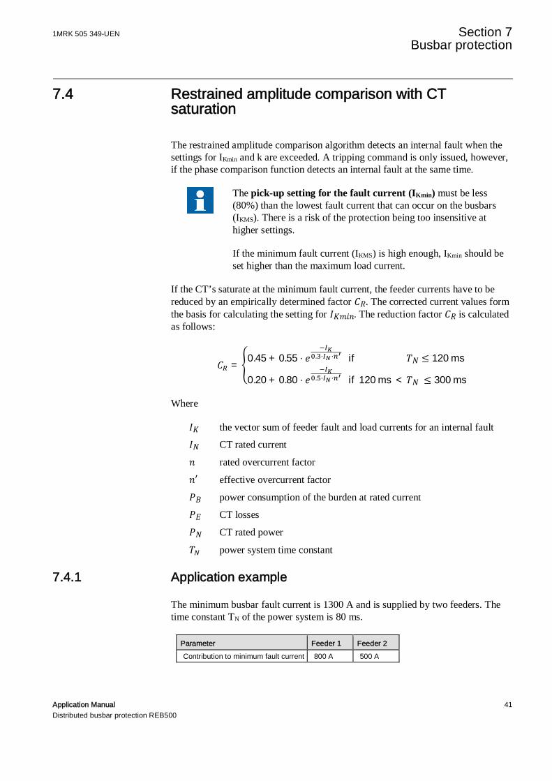
7.4.1 Application example
The minimum busbar fault current is 1300 A and is supplied by two feeders. Thetime constant TN of the power system is 80 ms.
Parameter Feeder 1 Feeder 2Contribution to minimum fault current 800 A 500 A
Section 7 1MRK 505 349-UENBusbar protection
42 Application ManualDistributed busbar protection REB500
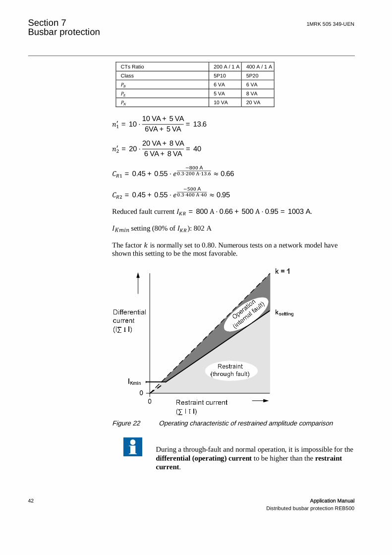
CTs Ratio 200 A / 1 A 400 A / 1 AClass 5P10 5P20
6 VA 6 VA5 VA 8 VA10 VA 20 VA
= 10 ⋅10VA + 5VA6VA + 5VA
= 13.6
= 20 ⋅20VA + 8VA6VA + 8VA
= 40
= 0.45 + 0.55 ⋅A
. ⋅ A⋅ . ≈ 0.66
= 0.45 + 0.55 ⋅A
. ⋅ A⋅ ≈ 0.95
Reduced fault current = 800A ⋅ 0.66 + 500A ⋅ 0.95 = 1003A.
setting (80% of ): 802 A
The factor is normally set to 0.80. Numerous tests on a network model haveshown this setting to be the most favorable.
Figure 22 Operating characteristic of restrained amplitude comparison
During a through-fault and normal operation, it is impossible for thedifferential (operating) current to be higher than the restraintcurrent.
1MRK 505 349-UEN Section 7Busbar protection
Application Manual 43Distributed busbar protection REB500
Other parameters may also influence the setting in extreme cases. These are ex-plained in the following examples.
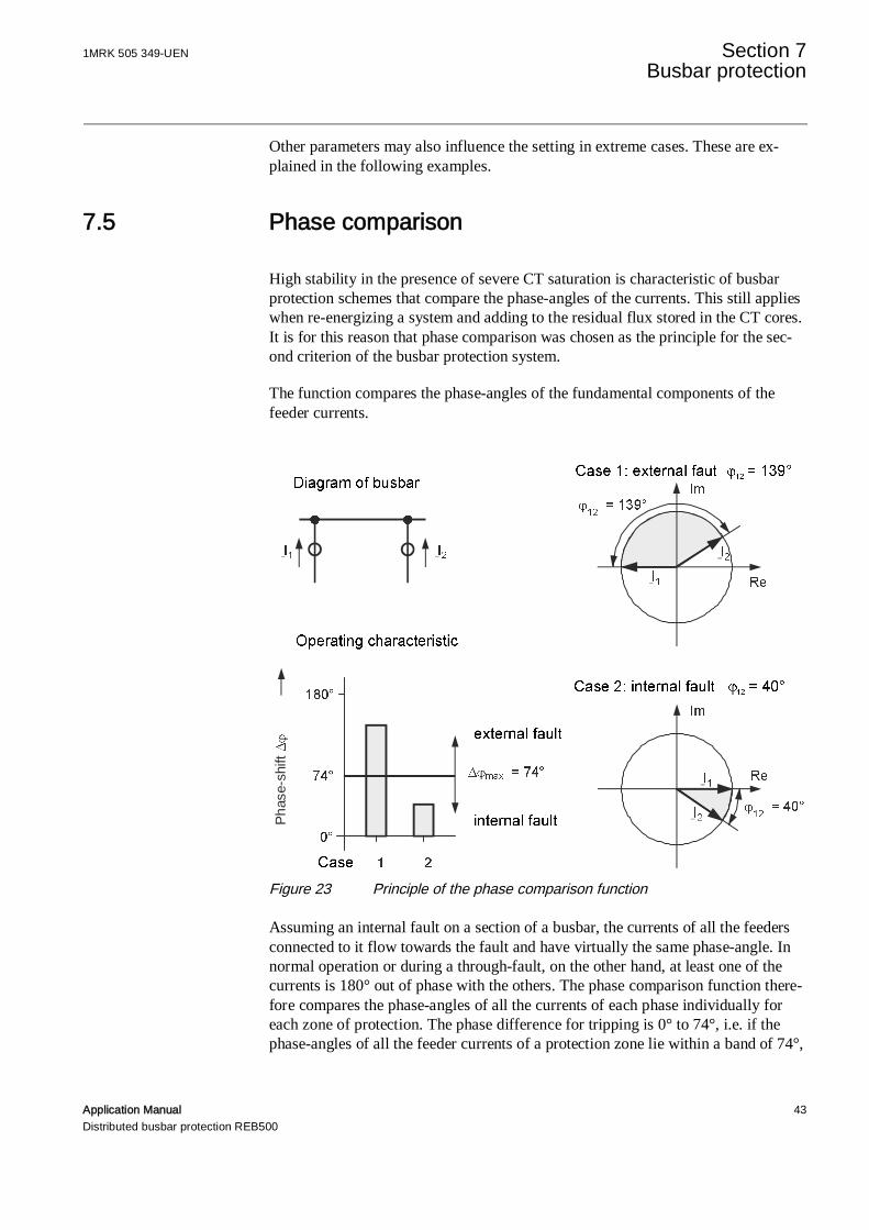
7.5 Phase comparison
High stability in the presence of severe CT saturation is characteristic of busbarprotection schemes that compare the phase-angles of the currents. This still applieswhen re-energizing a system and adding to the residual flux stored in the CT cores.It is for this reason that phase comparison was chosen as the principle for the sec-ond criterion of the busbar protection system.
The function compares the phase-angles of the fundamental components of thefeeder currents.
Figure 23 Principle of the phase comparison function
Assuming an internal fault on a section of a busbar, the currents of all the feedersconnected to it flow towards the fault and have virtually the same phase-angle. Innormal operation or during a through-fault, on the other hand, at least one of thecurrents is 180° out of phase with the others. The phase comparison function there-fore compares the phase-angles of all the currents of each phase individually foreach zone of protection. The phase difference for tripping is 0° to 74°, i.e. if thephase-angles of all the feeder currents of a protection zone lie within a band of 74°,
Phas
e-sh
ift
Section 7 1MRK 505 349-UENBusbar protection
44 Application ManualDistributed busbar protection REB500
the phase comparison function decides that there is an internal fault. The pick-upangle Dj of 74° is a fixed setting.
For proper operation, it is necessary to exclude feeders conducting very little or nocurrent from the comparison to prevent noise generated by them or balancing cur-rents during a fault from disturbing the measurement. A minimum current is there-fore determined when engineering the scheme for a particular application belowwhich a feeder is excluded from the phase comparison. Typical settings are 0.8for the phase currents and 0.25 for the neutral current.
7.6 Case studies: busbar layouts
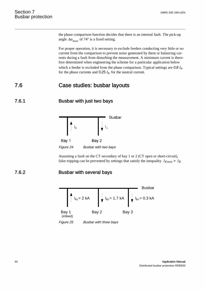
7.6.1 Busbar with just two bays
Figure 24 Busbar with two bays
Assuming a fault on the CT secondary of bay 1 or 2 (CT open or short-circuit),false tripping can be prevented by settings that satisfy the inequality > .
7.6.2 Busbar with several bays
Figure 25 Busbar with three bays
Bay 2 Bay 3
Busbar
IB1= 2 kA
Bay 1(infeed)
IB2 = 1.7 kA IB3 = 0.3 kA

1MRK 505 349-UEN Section 7Busbar protection
Application Manual 45Distributed busbar protection REB500
7.6.2.1 Case a: CT circuit fault on Bay 1
The CT circuit fault simulates a fault on the busbars with a currentD = 2 + 3 = 2kA. False tripping can be avoided by setting > 2kA,e.g. the next higher setting 2.1 kA.
7.6.2.2 Case b: CT circuit fault on Bay 2
The CT circuit fault in this case simulates a fault on the busbars with a fault currentD = 2 − 3 = 1.7kA and becomes:
=∆∑| | =
−+
=1.7kA2.0kA
≈ 0.74
False tripping can thus be avoided by setting > 1.7kA and/or > 0.74.
7.6.2.3 Case c: CT circuit fault on Bay 3
This case corresponds to the previous case, but the values for D and are lower:
D = 1 − 2 = 0.3kA
=∆∑| | =
−+
=0.3kA3.7kA
≈ 0.081 → ≪ 0.7
A CT circuit fault under normal load conditions cannot cause false tripping.
7.6.2.4 Influence of the phase comparison function
Tripping can only take place when both functions (restrained amplitude compari-son and phase comparison) detect an internal fault. The decision reached by thephase comparison function is therefore of no consequence in the cases illustrated inthis section.
7.6.2.5 Summary
Considering case a, the pick-up setting for the fault current in the example givenmust be > 2kA. This is the only setting which will prevent tripping in casea. Both settings, = 0.80 and > 1.7kA prevent tripping in case b, and adangerous setting is impossible in case c.
Assuming a minimum fault current higher than 2.1 kA, the settings for the aboveexample become = 0.80 and > 2.1kA. For a minimum fault current
Section 7 1MRK 505 349-UENBusbar protection
46 Application ManualDistributed busbar protection REB500
lower than 2.1 kA or even lower than the maximum load current of 2 kA, the set-ting of IKmin can result in both a failure of the protection to trip when it should or afalse trip:
• With a setting of > 2kA, the protection in the above example would notdetect a minimum fault current of 2 kA (excluding a CT fault).
• With a setting of < 2kA, a fault in the CT circuit according to case awould cause a false trip.
The best solution in this situation is to set to 80% of the minimum fault cur-rent .
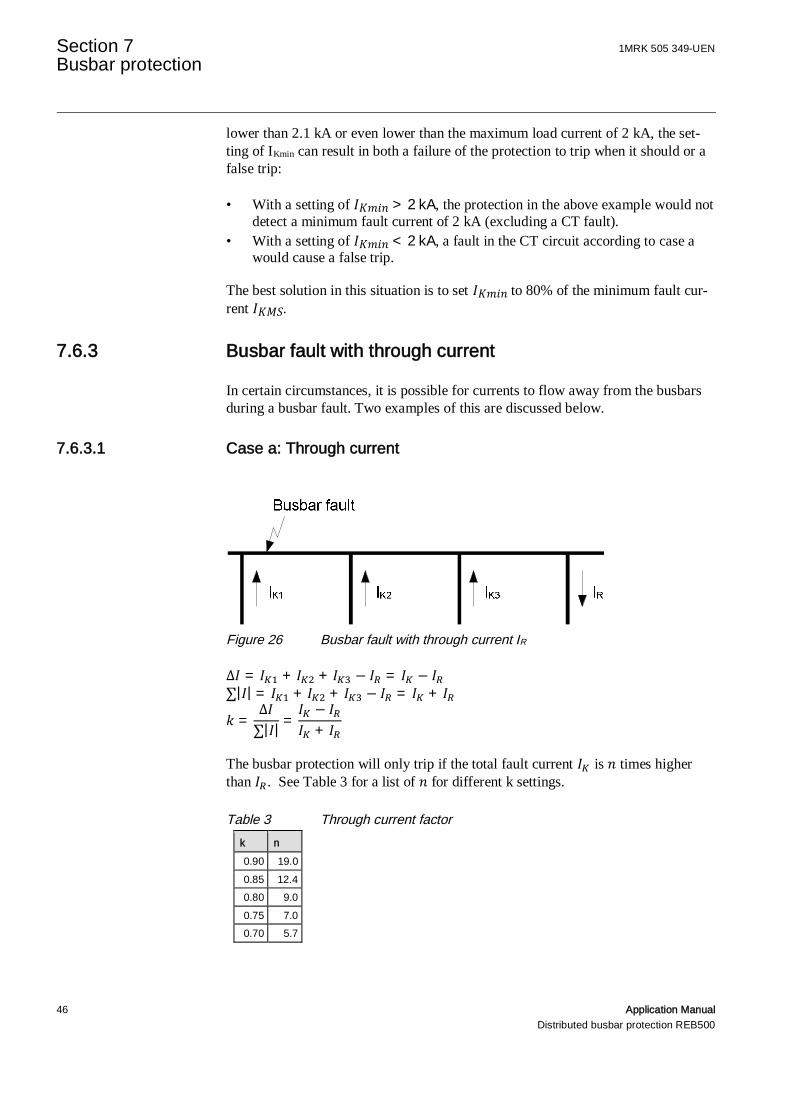
7.6.3 Busbar fault with through current
In certain circumstances, it is possible for currents to flow away from the busbarsduring a busbar fault. Two examples of this are discussed below.
7.6.3.1 Case a: Through current
Figure 26 Busbar fault with through current IR
∆ = + + − = − ∑| | = + + − = +
=∆∑| | =
−+
The busbar protection will only trip if the total fault current is times higherthan . See Table 3 for a list of for different k settings.
Table 3 Through current factork n0.90 19.00.85 12.40.80 9.00.75 7.00.70 5.7

1MRK 505 349-UEN Section 7Busbar protection
Application Manual 47Distributed busbar protection REB500
For the phase comparison function not to prevent tripping, the lowcurrent check for including feeder currents in the phase comparison(see Section 7.5 “Phase comparison”) must be set higher than thethrough current . This must be determined when engineering thescheme. An alternative is to disable the phase comparison function,which also must be determined when engineering the scheme.
7.6.3.2 Case b: Loop current
Figure 27 Busbar fault with a loop current
∆ = + + + − =
The busbar protection will only trip if the total fault current is times higherthan . See Table 4 for a list of typical values of
Table 4 Loop current factork n0.90 18.00.85 11.40.80 8.00.75 6.00.70 4.7
For the phase comparison function not to prevent tripping, the lowcurrent check for including feeder currents in the phase comparisonmust be set higher than the loop current . This must be determinedwhen engineering the scheme. An alternative is to disable the phasecomparison function, which also must be determined when engi-neering the scheme.
Busbar fault
IK3IQIQIK2IK1
Section 7 1MRK 505 349-UENBusbar protection
48 Application ManualDistributed busbar protection REB500
7.7 Differential current supervision
Supervising the differential current is an important supervision algorithm whichdetects the following protection system faults:
• short-circuited CTs• faulty CTs• wrong CT ratios• incorrectly wired CT (wrong current directions and therefore phases)• wrong isolator and circuit-breaker return confirmation signals
Supervising the differential current therefore augments the supervi-sion of the isolator and circuit-breaker statuses (see Section 6.2.1).
The differential current supervision feature forms part of the busbar protectionfunction and uses the same setting. Its operating value is set to a percentage of theminimum fault current .
If the differential current exceeds the setting for a time longer than the time setting,differential current alarm appears on the local HMI and the external signal“41815_Diff. current alarm” is generated.
The alarm and any blocking that has taken place are only reset after the differentialcurrent has disappeared again.
To ensure that faults can still be detected under low load conditions, the operatingvalue of the differential alarm must be set lower than the lowest possible load cur-rent.
Provision is made for the differential current alarm to block the protection (config-uration) in the event of differential alarm. There are two alternative settings:
• Selective blocking (preferred)Operation of the busbar protection is only blocked for the section of busbar(protection zone) concerned. Intertripping (see Section 6.1) by other protectionfunctions is still possible.
• Block protection completelyOperation of the entire protection system is blocked.
1MRK 505 349-UEN Section 8Special applications of BBP
Application Manual 49Distributed busbar protection REB500
Section 8 Special applications of BBP
8.1 Neutral current measurement
Measurement of the neutral current is only enabled for impedancegrounded power systems and at the user’s specific request.
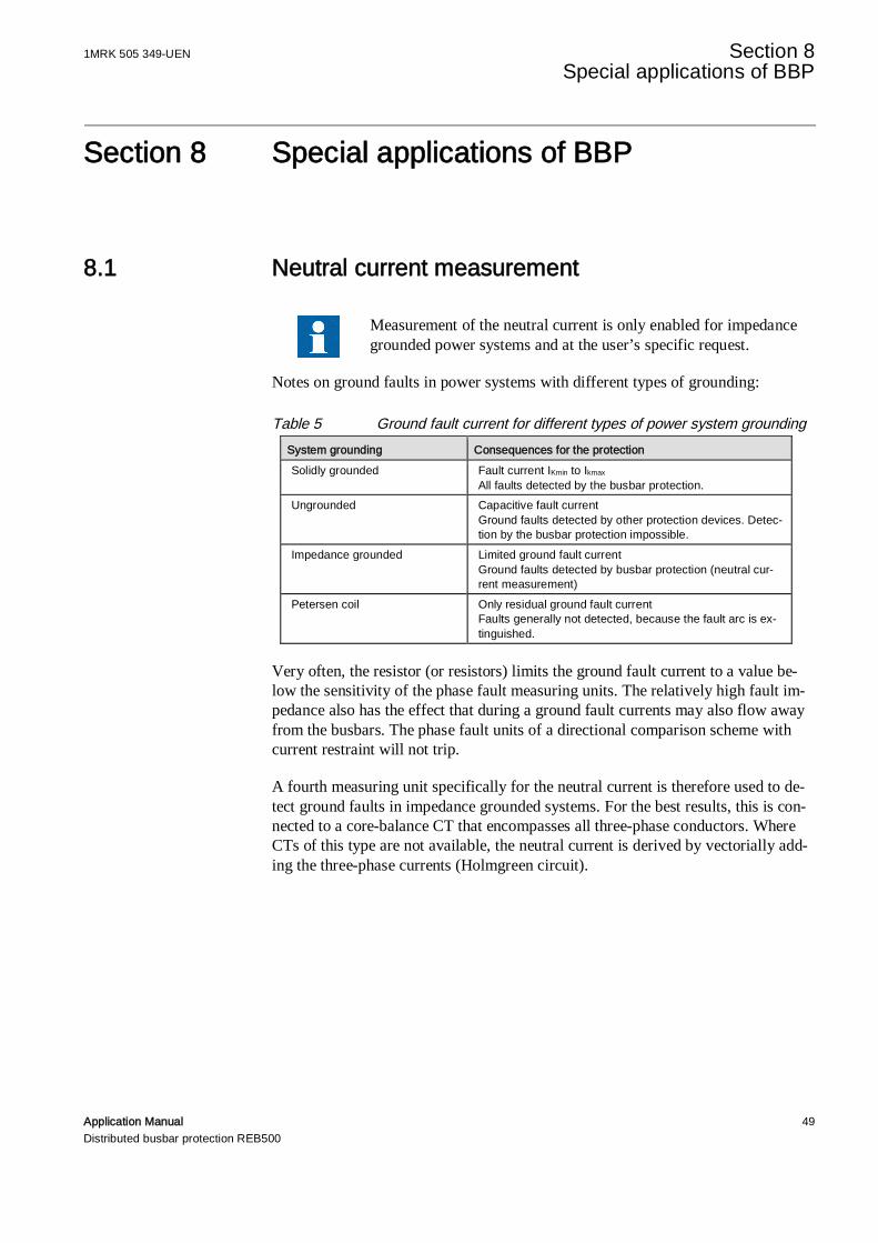
Notes on ground faults in power systems with different types of grounding:
Table 5 Ground fault current for different types of power system groundingSystem grounding Consequences for the protectionSolidly grounded Fault current IKmin to Ikmax
All faults detected by the busbar protection.Ungrounded Capacitive fault current
Ground faults detected by other protection devices. Detec-tion by the busbar protection impossible.
Impedance grounded Limited ground fault currentGround faults detected by busbar protection (neutral cur-rent measurement)
Petersen coil Only residual ground fault currentFaults generally not detected, because the fault arc is ex-tinguished.
Very often, the resistor (or resistors) limits the ground fault current to a value be-low the sensitivity of the phase fault measuring units. The relatively high fault im-pedance also has the effect that during a ground fault currents may also flow awayfrom the busbars. The phase fault units of a directional comparison scheme withcurrent restraint will not trip.
A fourth measuring unit specifically for the neutral current is therefore used to de-tect ground faults in impedance grounded systems. For the best results, this is con-nected to a core-balance CT that encompasses all three-phase conductors. WhereCTs of this type are not available, the neutral current is derived by vectorially add-ing the three-phase currents (Holmgreen circuit).

Section 8 1MRK 505 349-UENSpecial applications of BBP
50 Application ManualDistributed busbar protection REB500
Figure 28 Impedance grounded network
Where this solution is chosen, it is necessary to check the performance of theREB500 neutral current measurement with respect to the main CTs, power systemtime constant, fault current levels and power transformer inrush current.
The configuration of the busbar protection in impedance grounded networks musttake the following physical conditions into account:
• Limited single-phase to ground fault current levels (Ikmin 1ph and k-factor val-ues are possibly lower than the operating range of the phase measurement system).
• For a single-phase fault on the busbar, current can also flow away from the bus-bar because of the relatively high fault impedance (Ib). As a consequence, the phasecomparison system may not be able to trip (since the phase-angle between and| + | exceeds 74°).
At a fault current corresponding to twice the load current , flowing in the af-fected phase L1, the restraining factor k is only 0.5. Thus the restrained amplitudecomparison function cannot detect the internal fault at the usual k setting of 0.80.Furthermore, the current is flowing away from the busbar so the phase comparisonmeasures a phase-angle of approximately 180° thus preventing the trip command.Therefore the neutral current I0 has to be measured as well and evaluated togetherwith the restrained amplitude comparison and the phase comparison functions.
The neutral current evaluation is only necessary by phase-to-ground faults andshould only be used for these faults. The monitoring of the conductor currentsserves as the measuring criteria. Whether it is included in the evaluation or not de-pends on the levels of the phase currents. Even if the phase currents do not drivethe CTs into saturation, their ratio errors can still produce an apparent neutral cur-rent on the secondary side. The neutral current is therefore only evaluated when
L1 L2 L3
Ik
I +Ik b
+Ib
|I +I -I |k b bk = |I +I |+|I |k b b
I = 2Ik b
k = 0,5
HEST 985008 C
1MRK 505 349-UEN Section 8Special applications of BBP
Application Manual 51Distributed busbar protection REB500
none of the phase currents exceeds a set value (typically 5 IN). This prevents theneutral current from being evaluated for phase-to-phase and three-phase faults.
Finally, the harmonic level is monitored to ensure that the neutral current is onlyevaluated providing the measurement is uninfluenced by CT saturation. This fea-ture also prevents the evaluation of the neutral current during transformer inrushcurrents.
To ensure that the neutral current supervision function blocks relia-bly in the event of CT saturation, the inductive component of theburden must be a minimum. Therefore the CT secondary circuitmust not include electromechanical relays or similar devices.
Detailed site data are essential to accurately engineer and set the neutral currentmeasuring systems.
For each busbar section
IKS3max max. phase fault current for a three-phase fault
TS3max time constant of the DC component of lS3max
IKS3min min. phase fault current for a three-phase fault
TS3min time constant of the DC component of IKS3min
IKS1max max. fault current for a phase-to-ground fault
TS1max time constant of the DC component of IKS1max
IKS1min min. fault current for a phase-to-ground fault
TS1min time constant of the DC component of IKS1min
For each feeder
IKA1max max. fault current for a phase-to-ground fault
TA1max time constant of the DC component of IKA1max
IBAmax max. load current
INprim rated CT primary current
INsec rated CT secondary current
PN rated CT power in VA
n rated CT overcurrent factor
n’ effective CT overcurrent factor
UK CT knee-point voltage
PE CT losses
Section 8 1MRK 505 349-UENSpecial applications of BBP
52 Application ManualDistributed busbar protection REB500
RCT resistance of the CT secondary winding
l single length (not loop) of the CT leads in Ohm
A gauge of CT leads in mm2
PBG total burdens of all connected devices in VA
RBG total resistive burdens of all connected devices in Ohm
The following points must be checked:
• through-fault stability of the I0 measuring system• lowest permissible current (operating current) for the differential current meas-
urement• CT knee-point voltage in relation to the required operating range of the I0
measuring system (it must not saturate in the operating range).
Instructions for calculation and the requirements to be fulfilled by the CTs aregiven in detail in the application description “Ground fault protection for high volt-age busbars” (1KHL020319-Aen).
8.2 Blocking measurement of certain CTs
The operation of the busbar protection is explained for simple sta-tion configuration in this section. Its application to complex sta-tions is described in Section 12.
Blocking the measurement of a CT means that its current is ex-cluded from evaluation by the busbar protection function even ifit was assigned by the intertripping system.
Blocking is necessary for bus-tie breakers (see Section 8.2.1) and may be necessaryfor feeders (see Section 8.2.2).
In certain conditions blocking of the measurement is delayed (reclaim time) (seeSection 8.2.3).
Blocking is cancelled as soon as the cause for it has disappeared and the protectionsystem receives an active “CB CLOSE” signal (see Section 8.2.4).
Blocking the measurement of certain CTs is a basic function of the busbar protec-tion, which, with the exception of the circuit-breaker reclaim time and the binaryinputs for the circuit-breaker statuses and “CB CLOSE” signals, must be neitherconfigured nor set.

1MRK 505 349-UEN Section 8Special applications of BBP
Application Manual 53Distributed busbar protection REB500
8.2.1 Bus-tie breaker functions
In the case of a bus-tie breaker with a single set of CTs, the cur-rent measurement is assigned to both protection zones, to one in aninverted sense.
Blocking this measurement applies to both zones.
Two bay units are necessary in the case of a bus-tie breaker withtwo sets of CTs. The current measurements are assigned to the pro-tection zones such that they overlap. A fault between the sets of CTsthus trips both zones. The inversion of one of the current signals isachieved by wiring it appropriately to the REB500 analog input.
Blocking this measurement applies to both zones.
The busbar protection excludes the bus-tie breaker CT from evaluation under thefollowing conditions.
• When the bus-tie breaker is open (see Section 8.2.1.1).• When a station protection function (BBP, BFP or EFP) issues an internal inter-
tripping command to the respective breaker (see Section 8.2.1.2).• When the CTs are bridged (see Section 8.2.1.3).
8.2.1.1 When the bus-tie breaker is open
The bus-tie breaker measurement is blocked when the breaker is open in order totrip the busbar section effectively concerned for a fault between a single set of CTsand the bus-tie breaker.
The CTs are not assigned to a protection zone when the bus-tie breaker is open andtherefore the protection zones extend to the bus-tie breaker itself. The correct zonecan thus be tripped for a fault between the CTs and the bus-tie breaker.
Figure 29 Bus-tie breaker (open) and two sets of CTs
This operation also applies to bus-tie breakers with only a single set of CTs.

Section 8 1MRK 505 349-UENSpecial applications of BBP
54 Application ManualDistributed busbar protection REB500
8.2.1.2 In the event of a protection function (BBP, BFP or EFP) tripping thisCB
When a bus-tie breaker is closed, its measurement is blocked when a protectionfunction BBP, BFP or EFP issues a tripping command.
Bus-tie breaker with a single set of CTs
To trip the section of busbar effectively concerned as quickly as possible for a faultbetween the closed circuit-breaker and the CTs.
Where a bus-tie breaker is equipped with only one set of CTs, the latter is used forboth the neighboring protection zones and is automatically assigned to them whenconfiguring the system.
Faults on bus zone II are tripped immediately and discriminatively in protectionzone II. Faults on bus zone I but not between the CTs and the bus-tie breaker arealso tripped immediately and discriminatively in protection zone I.
A fault between the CTs and the bus-tie breaker (i.e. on bus zone I but in protectionzone II) trips initially protection zone II (including the bus-tie breaker) immedi-ately, i.e. the bus zone not involved in the fault.
A fault between the CTs and a closed bus-tie breaker is tripped afterthe reclaim time.
Bus-tie breaker with one or two sets of CTs
Detecting a possible breaker failure:
See Figure 31 Bus-tie breaker (closed) and two sets of CTs.
In the case of bus-tie breakers with a set of CTs on both sides, both are assigned tomeasuring systems. CT 2 is the limit of protection zone I and CT 1 the limit of pro-tection zone II. A bay unit is needed for each set of CTs.
Both sets of CTs do not have to be used and if only one is configured, the schemeis the same as described in the section for bus-tie breakers with a single set of CTs.
The function is the same as for bus-tie breakers with a single set of CTs.

1MRK 505 349-UEN Section 8Special applications of BBP
Application Manual 55Distributed busbar protection REB500
Figure 30 Bus-tie breaker (closed) and one set of CTs
Figure 31 Bus-tie breaker (closed) and two sets of CTs
8.2.1.3 Short-circuiting of a CT
The bus-tie breaker is excluded from the measurement when bus zones are alsoconnected by an isolator, for example:
1. Coupled transversely by parallel isolators2. Coupled longitudinally by parallel longitudinal isolators
Concerning 1. Coupled transversely by parallel isolators
The current flowing via the coupling between the busbars (Figure 32) is repre-sented in the busbar protection by two current vectors of opposite direct (V+, V-).The vectors are assigned according to measuring system S1 (vector V+) and S2(vector V-).
When switching a feeder from busbar S1 to S2 (load switching), both isolators Q1and Q2 are closed for a certain time, i.e. busbars S1 and S2 are directly connected.
• During this time, measuring systems S1 and S2 are connected to form onecommon measuring system (S1/S2) to match the primary system.
• For the same time the bus-tie breaker measurement is blocked, i.e. the twovectors V+ and V- are excluded.
The reasons for blocking the bus-tie breaker measurement are the following:
While the busbar sections are in parallel (Q1 and Q2 closed), the current (Ik1) ofany fault that occurs will divide into a part flowing directly (Ik11) and a part flow-ing via the bus-tie breaker (Ik12). If included, the bus-tie breaker current (Ik12)
Bus zone I
Protection zone I
CTs 1
Bus zone II
Protection zone II
CTs 2
Bus-tie breaker

Section 8 1MRK 505 349-UENSpecial applications of BBP
56 Application ManualDistributed busbar protection REB500
would be represented by the two vectors with opposing directions (V+, V-) andassigned to the common measuring system (S1/S2). The consequence would bethat the
1. directional comparison of S1/S2 would prevent any tripping because the oppo-sition of the current vectors (V+, V-) does not point to a fault on the busbars(see Section 7.4).
2. restrained differential current measurement S1/S2 would see a restraint currentlarger by double the bus-tie breaker current and this would reduce the stabili-zation factor K to a value lower than setting (see Section 7.2.2).
Blocking the bus-tie breaker measurement excludes the two vectors V+ and V-from the measurement so that they cannot prevent tripping.
Figure 32 Bus-tie breaker with isolators closed in parallel
Concerning 2. Longitudinal bus-tie breaker with longitudinal isolatorsclosed in parallel
The bus-tie breaker in Figure 33 connects busbar sections longitudinally together.
In order to connect the sections of busbar 3 to left and right of the longitudinal iso-lators (3A and 3B) together, the longitudinal bus-tie breaker has to be closed first.The longitudinal isolator Q31 can then be closed. The situation is shown in the dia-gram.
This is analogous to the situation described under 1. above (transverse bus-tiebreaker), i.e. measuring systems 3A and 3B are combined to a single measuringsystem (3A/3B). The problem is thus also the same and the bus-tie breaker meas-urement must also be blocked.
S2S1
Q1 Q2
Ik1
Ik11
Ik12
Ik12
V+V-

1MRK 505 349-UEN Section 8Special applications of BBP
Application Manual 57Distributed busbar protection REB500
Figure 33 Longitudinal bus-tie breaker
8.2.2 Feeder circuit-breakers
In the case of a feeder circuit-breaker, measurement of the CT forthe busbar protection is blocked when
• a feeder has the CT on the line side of the circuit-breaker(see Figure 34); and
• the auxiliary contacts on the circuit-breaker (see Section6.2.) and the “CB CLOSE” signal (see Section 8.2.4) areconfigured in the protection system; and
• the circuit-breaker is opened or a protection function (BBP,BFP or EFP) issues an internal intertripping command to thecircuit-breaker.
In these circumstances (see Figure 34), the measurement by the bay unit has to beblocked to prevent the busbar protection from tripping for a fault between the cir-cuit-breaker and the CTs when the circuit-breaker is open, because the fault is inthe protection zone of the end fault protection and not the busbar protection.
Blocking the measurement is unnecessary for a CT on the busbarside of the circuit-breaker (see Figure 35), because the fault is out-side the busbar protection zone and can only be detected and trippedby the end fault protection.
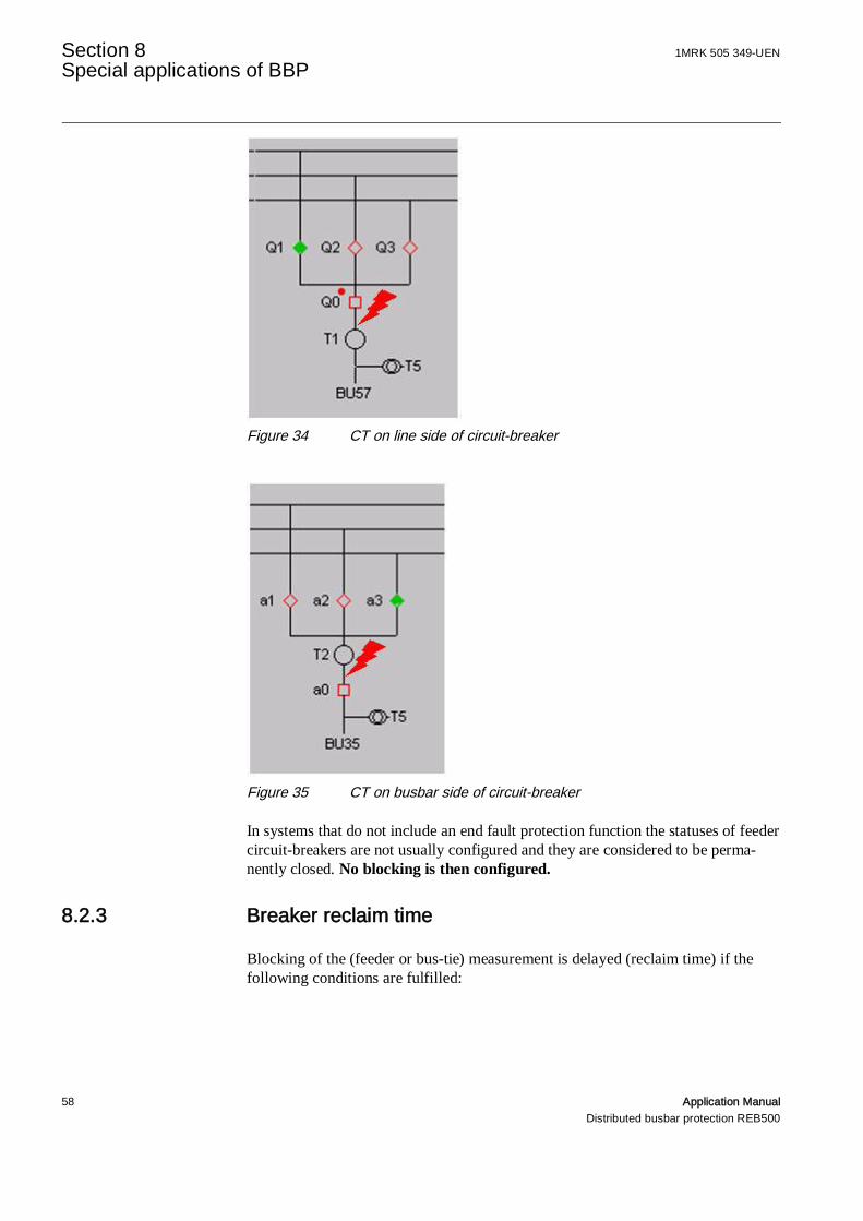
Section 8 1MRK 505 349-UENSpecial applications of BBP
58 Application ManualDistributed busbar protection REB500
Figure 34 CT on line side of circuit-breaker
Figure 35 CT on busbar side of circuit-breaker
In systems that do not include an end fault protection function the statuses of feedercircuit-breakers are not usually configured and they are considered to be perma-nently closed. No blocking is then configured.
8.2.3 Breaker reclaim time
Blocking of the (feeder or bus-tie) measurement is delayed (reclaim time) if thefollowing conditions are fulfilled:
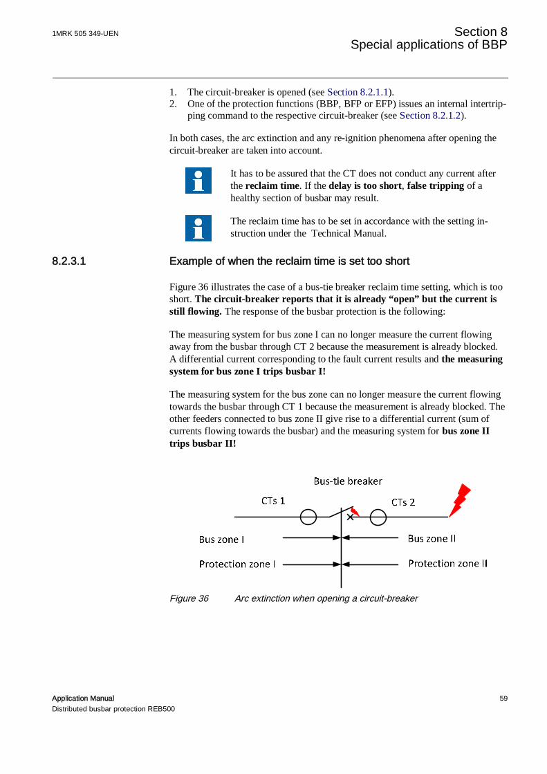
1MRK 505 349-UEN Section 8Special applications of BBP
Application Manual 59Distributed busbar protection REB500
1. The circuit-breaker is opened (see Section 8.2.1.1).2. One of the protection functions (BBP, BFP or EFP) issues an internal intertrip-
ping command to the respective circuit-breaker (see Section 8.2.1.2).
In both cases, the arc extinction and any re-ignition phenomena after opening thecircuit-breaker are taken into account.
It has to be assured that the CT does not conduct any current afterthe reclaim time. If the delay is too short, false tripping of ahealthy section of busbar may result.
The reclaim time has to be set in accordance with the setting in-struction under the Technical Manual.
8.2.3.1 Example of when the reclaim time is set too short
Figure 36 illustrates the case of a bus-tie breaker reclaim time setting, which is tooshort. The circuit-breaker reports that it is already “open” but the current isstill flowing. The response of the busbar protection is the following:
The measuring system for bus zone I can no longer measure the current flowingaway from the busbar through CT 2 because the measurement is already blocked.A differential current corresponding to the fault current results and the measuringsystem for bus zone I trips busbar I!
The measuring system for the bus zone can no longer measure the current flowingtowards the busbar through CT 1 because the measurement is already blocked. Theother feeders connected to bus zone II give rise to a differential current (sum ofcurrents flowing towards the busbar) and the measuring system for bus zone IItrips busbar II!
Figure 36 Arc extinction when opening a circuit-breaker

Section 8 1MRK 505 349-UENSpecial applications of BBP
60 Application ManualDistributed busbar protection REB500
8.2.4 “CB CLOSE” command (manual close signal)
In order to be prepared for closing the breaker onto an existing fault (e.g. closedgrounding isolator or forgotten grounding clamp), the measurement has to be rein-stated before the feeder or bus-tie breaker is actually closed. This is achieved byactivating the busbar protection input signal “11505_Close command CB”.
The “CLOSE CB” command instantly cancels any previousblocking of measurement regardless of all other criteria.
As soon as the circuit-breaker has reached the closed status (auxiliary contacts re-port CLOSED), the “CLOSE CB” command can reset.
The “CLOSE CB” command must be maintained until the cir-cuit-breaker “CLOSED” auxiliary contact has definitely closed (theauxiliary contacts overlap).
To avoid any risk of mal-operation, the protection must registerevery signal applied to the circuit-breaker “CLOSE” coil. Theseinclude, for example, local close commands, close commands fromremote control systems, the station automation system or from auto-reclosure schemes.
The simplest way of doing this is to take the “CLOSE CB” signaldirectly from the circuit-breaker “CLOSE” coil.
The CLOSE CB signal is acquired and processed every 6 ms (fast part and fast sig-nal).
8.2.4.1 Example of a “CLOSE CB” signal which was not registered
Figure 37 shows the case of closing onto an existing fault (e.g. closed groundingisolator or forgotten grounding clamp) when the “CLOSE CB” command was notregistered by the protection.
The arc ignites before the circuit-breaker can report that it is closed:
The measuring system for bus zone I is unable to measure the outgoing fault cur-rent towards bus zone II, because the measurement of the bus-tie breaker current isstill blocked. A differential current equivalent to the fault current is therefore cre-ated and the measuring system for bus zone I trips busbar I.
The measuring system for bus zone II is unable to measure the incoming fault cur-rent flowing from bus zone I, because the measurement of the bus-tie breaker cur-rent is still blocked. Since, however, there are no other feeders connected to buszone II that could produce a differential current, the bus zone II measuring sys-tem does not trip.
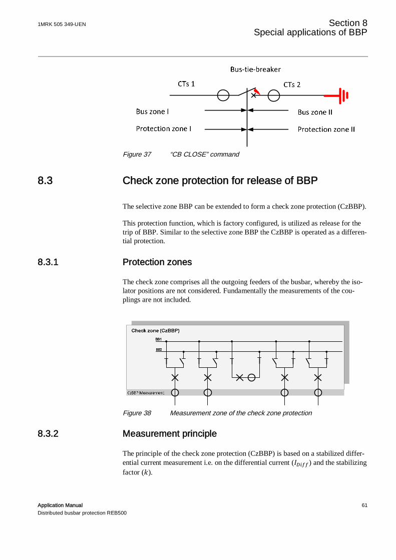
1MRK 505 349-UEN Section 8Special applications of BBP
Application Manual 61Distributed busbar protection REB500
Figure 37 “CB CLOSE” command
8.3 Check zone protection for release of BBP
The selective zone BBP can be extended to form a check zone protection (CzBBP).
This protection function, which is factory configured, is utilized as release for thetrip of BBP. Similar to the selective zone BBP the CzBBP is operated as a differen-tial protection.
8.3.1 Protection zones
The check zone comprises all the outgoing feeders of the busbar, whereby the iso-lator positions are not considered. Fundamentally the measurements of the cou-plings are not included.
Figure 38 Measurement zone of the check zone protection
8.3.2 Measurement principle
The principle of the check zone protection (CzBBP) is based on a stabilized differ-ential current measurement i.e. on the differential current ( ) and the stabilizingfactor ( ).
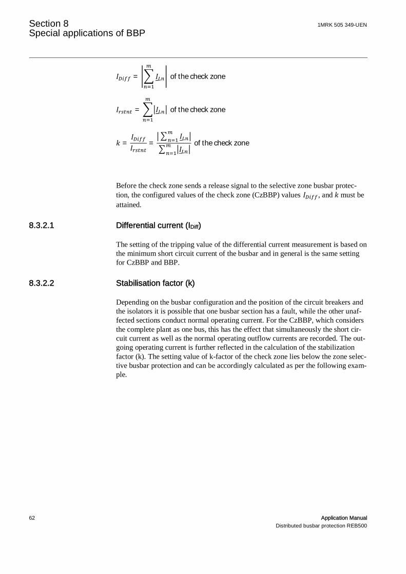
Section 8 1MRK 505 349-UENSpecial applications of BBP
62 Application ManualDistributed busbar protection REB500
= ofthecheckzone
= ofthecheckzone
= = ofthecheckzone
Before the check zone sends a release signal to the selective zone busbar protec-tion, the configured values of the check zone (CzBBP) values , and must beattained.
8.3.2.1 Differential current (IDiff)
The setting of the tripping value of the differential current measurement is based onthe minimum short circuit current of the busbar and in general is the same settingfor CzBBP and BBP.
8.3.2.2 Stabilisation factor (k)
Depending on the busbar configuration and the position of the circuit breakers andthe isolators it is possible that one busbar section has a fault, while the other unaf-fected sections conduct normal operating current. For the CzBBP, which considersthe complete plant as one bus, this has the effect that simultaneously the short cir-cuit current as well as the normal operating outflow currents are recorded. The out-going operating current is further reflected in the calculation of the stabilizationfactor (k). The setting value of k-factor of the check zone lies below the zone selec-tive busbar protection and can be accordingly calculated as per the following exam-ple.

1MRK 505 349-UEN Section 8Special applications of BBP
Application Manual 63Distributed busbar protection REB500
Figure 39 Determination of the stabilizing factors (k)
=|1.5kA + 2.0kA − 2.0kA|
|1.5kA| + |2.0kA| + |−2.0kA| =1.5kA5.5kA
= 0.27
In the above example, the stabilization factor setting (k) for the check zone(CzBBP) is k = 0.25 (next setting below the calculated value of k = 0.27). The set-ting for the selective zone (BBP) has to be calculated according to Section 7.3 andis typically k = 0.8.
8.3.2.3 Operating characteristic
This results in the following operating characteristic for CzBBP: The region abovethe thick line is the operating zone.
Check zone (CzBBP)BB1
BB 2
CzBBP Measurement IKmin=1.5kA I Bmax =2. 0 kA IBmax =2. 0 kA

Section 8 1MRK 505 349-UENSpecial applications of BBP
64 Application ManualDistributed busbar protection REB500
Figure 40 Operating characteristic for the stabilized differential current meas-urement
8.3.3 Check zone
If the check zone (CzBBP) in a REB500 protection system picks up, zone selectivetripping of the busbar protection is permitted in the following cases:
Figure 41 Tripping in check zone enabled

1MRK 505 349-UEN Section 8Special applications of BBP
Application Manual 65Distributed busbar protection REB500
a) Trip by CzBBP enables tripping of the BBP zone.b) One or more bay units out of operation (i.e. switched off, loss of power, or de-
vice error), results in absence of important measurements categories. A com-plete check zone formation is not possible and thus leads to a release of thezone trip of the BBP (i.e. 'the check zone is bypassed').
c) If the binary input signal from a bay unit “12605_Bypass Check Zone“ or froma central unit “32605_Bypass Check Zone“ has been actuated a release of theBBP zone trip occurs ('the check zone is bypassed'). An application example isprovided in Section 8.3.5
d) If in the configuration software HMI500 (i.e. in the configuration database) thecheck zone protection is set to “not active”, then a permanent release of theBBP zone trip occurs ('the check zone is bypassed').
e) A differential current of the CzBBP leads to a bypass of the release of the BBPzone trip, in case the alarm mode “Check zone bypass” has also been set in theHMI500.
8.3.4 Application of check zone protection
If an incorrect feedback of the isolators / circuit breakers is provided to the selec-tive zone busbar protection (BBP), which is not in accordance to the actual imageof the plant, then the results of the busbar measurement and the calculation of theprotection criteria do not correspond to the real situation. This adverse situationcould lead to an incorrect tripping.
Especially in plants where the activation current of the differential current criteria(Idiff) is set below the maximum operating currents of the individual feeders, theeffect of incorrect isolator / circuit breaker positions has a very adverse effect.
The use of an overall check zone release criteria (CzBBP) which functions inde-pendent of the position of the isolator / circuit breaker eliminates the danger of un-desirable trippings.
Instead of a check zone release criteria (CzBBP) as an alternative the under voltagerelease criteria (U<) can also be utilized (see Technical Manual)
8.3.5 Substation configuration
As is described in the Section 8.3.2, all outgoing feeders of standard single anddouble busbar systems can be included in a check zone (CzBBP) measurement, butexclude the measurements from the couplers.
For complex busbar configurations e.g. 1½ - Breaker systems and complex multi-busbar systems, which measurements have to be used in the check zone protectionwill be determined during factory configuration.
For substations with transfer busbars, dependent on the configura-tion the following section has to be noted.

Section 8 1MRK 505 349-UENSpecial applications of BBP
66 Application ManualDistributed busbar protection REB500
Substations with a transfer busbar, depending on the configuration, have to betreated separately. If switching on a transfer busbar isolator results in bypassing theCT of an outgoing feeder such that the feeder is connected directly to the busbar(i.e. without measurement no valid check zone measurement (CzBBP) can be per-formed. In this case the binary input signal “12605_Bypass Check Zone” has to beconfigured for each bay unit associated with such an outgoing bypass feeder. Thepresence of the above signal results in an instantaneous unblocking (see Section8.3.3), which should be equated to a bypass of the check zone system. This binaryinput should be connected to closing the contact of the customary selector switch“Feeder in bypass operation”.
Figure 42 Double busbar with bypass
8.3.6 Maintenance conditions in connection with CzBBP
As described under the Technical Manual a signal can be applied to the binary in-puts “Inspection” and “Maintenance” which prevents the test injection current frombeing included in the differential current measurement of the busbar protection(BBP). This function relies on the position of the isolator concerned being set to'OFF' in the busbar image in the REB500.
The check zone protection (CzBBP) does not take any isolator position into consid-eration. This means that the test current of an outgoing feeder bay unit in the modi-fication or maintenance mode is included in the check zone calculation. Dependingon the level of the test current, the check zone (CzBBP) may pick up, however thebusbar protection (BBP) is uninfluenced by the differential current and prevents thepickup of the check zone from having any effect.
If it is desired that the check zone protection be bypassed (enabled) in the modifi-cation or maintenance mode, the signal ‘12605_Bypass Check Zone’ must be acti-vated in addition to the input ‘11620_Inspection_1-On’ or ‘11660_Maintenance-On’.
1MRK 505 349-UEN Section 9Breaker failure protection (BFP)
Application Manual 67Distributed busbar protection REB500
Section 9 Breaker failure protection (BFP)
9.1 Current setting
If the pick-up current of the breaker backup function is set too low there is a riskthat BFP will not reset quickly enough after a circuit-breaker has been successfullytripped. This can be the result of decaying oscillations in the CT secondary circuit.
Conversely BFP may fail to operate if the setting is too high. This situation couldarise, for example, due to severe CT saturation when the secondary current fallsbelow the setting and BFP does not start. Recommendations now follow which en-able the pick-up current of BFP to be correctly set in relation to the CT data (n')and the set time.
These setting recommendations apply for the phase measurementsystem of BFP only. If the supplemental neutral measurement sys-tem of BFP is activated, the information in Section 9.4 has to beconsidered in addition.
Basically, the current setting (IE) should be less than the minimum fault current of the corresponding feeder (approx. 80%, i.e. 0.8). Just to satisfy this condi-
tion, the setting would be:
= 0.8 ⋅
This setting may be too high for conventional iron core CTs because the measure-ment may not function correctly even at low fault currents due to transient compo-nents in the fault current. A failure of the breaker to operate will always be de-tected, but tripping could be delayed.
9.1.1 Iron core transformers (Class TPX) and transformers withresidual flux “air gap” (Class TPY)
It is necessary to know the transient overcurrent factor ( ∗) in order to design ascheme for operation with these CTs. This is calculated from the effective overcur-rent factor ′ as follows:
= ⋅++

Section 9 1MRK 505 349-UENBreaker failure protection (BFP)
68 Application ManualDistributed busbar protection REB500
∗ =1 + 2 ⋅ ⋅
After obtaining the transient overcurrent factor ( ∗), the settings are given by:
≤ min ∗,0.8 ⋅
TPX and TPY transformers differ, with respect to transient char-acteristics, by a small remanence in the case of the TPY type. Withregard to transient over-dimensioning, TPX and TPY hardly differ.
As an example consider the following values:
CT characteristic ValueRatio 600/5 ARated burden PN 15 VALosses PE 7 VARated overcurrent factor n 20Lead burden PB 10 VABay unit burden <0.1 VARated frequency f: 50 HzPower system time constant TN 80 msMinimum fault current IKmin 450 A
= 20 ⋅15VA + 7VA10VA + 7VA
= 25.88
∗ =25.88
1 + 2 ⋅ 50Hz ⋅ 0.08s=
25.8826.13
= 0.99
≤ min 0.99,0.8 ⋅ 450A
600A= min(0.99, 0.6) = 0.6
Hence, in this example we could set e.g. = 0.5 ⋅ .
9.1.2 Linearized current transformers (TPZ)
Since these CTs are scarcely subject to saturation, the setting is only based on theminimum fault current for the feeder:
= 0.8 ⋅
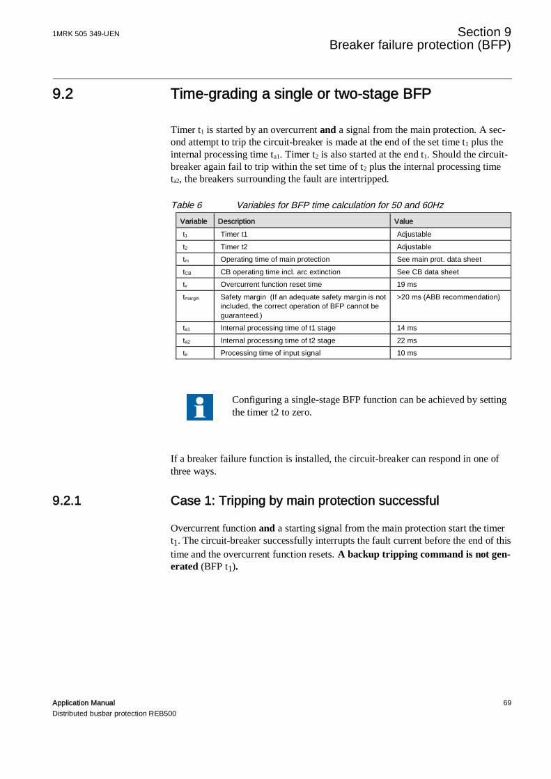
1MRK 505 349-UEN Section 9Breaker failure protection (BFP)
Application Manual 69Distributed busbar protection REB500
9.2 Time-grading a single or two-stage BFP
Timer t1 is started by an overcurrent and a signal from the main protection. A sec-ond attempt to trip the circuit-breaker is made at the end of the set time t1 plus theinternal processing time ta1. Timer t2 is also started at the end t1. Should the circuit-breaker again fail to trip within the set time of t2 plus the internal processing timeta2, the breakers surrounding the fault are intertripped.
Table 6 Variables for BFP time calculation for 50 and 60HzVariable Description Valuet1 Timer t1 Adjustablet2 Timer t2 Adjustabletm Operating time of main protection See main prot. data sheettCB CB operating time incl. arc extinction See CB data sheettv Overcurrent function reset time 19 mstmargin Safety margin (If an adequate safety margin is not
included, the correct operation of BFP cannot beguaranteed.)
>20 ms (ABB recommendation)
ta1 Internal processing time of t1 stage 14 msta2 Internal processing time of t2 stage 22 mste Processing time of input signal 10 ms
Configuring a single-stage BFP function can be achieved by settingthe timer t2 to zero.
If a breaker failure function is installed, the circuit-breaker can respond in one ofthree ways.
9.2.1 Case 1: Tripping by main protection successful
Overcurrent function and a starting signal from the main protection start the timert1. The circuit-breaker successfully interrupts the fault current before the end of thistime and the overcurrent function resets. A backup tripping command is not gen-erated (BFP t1).
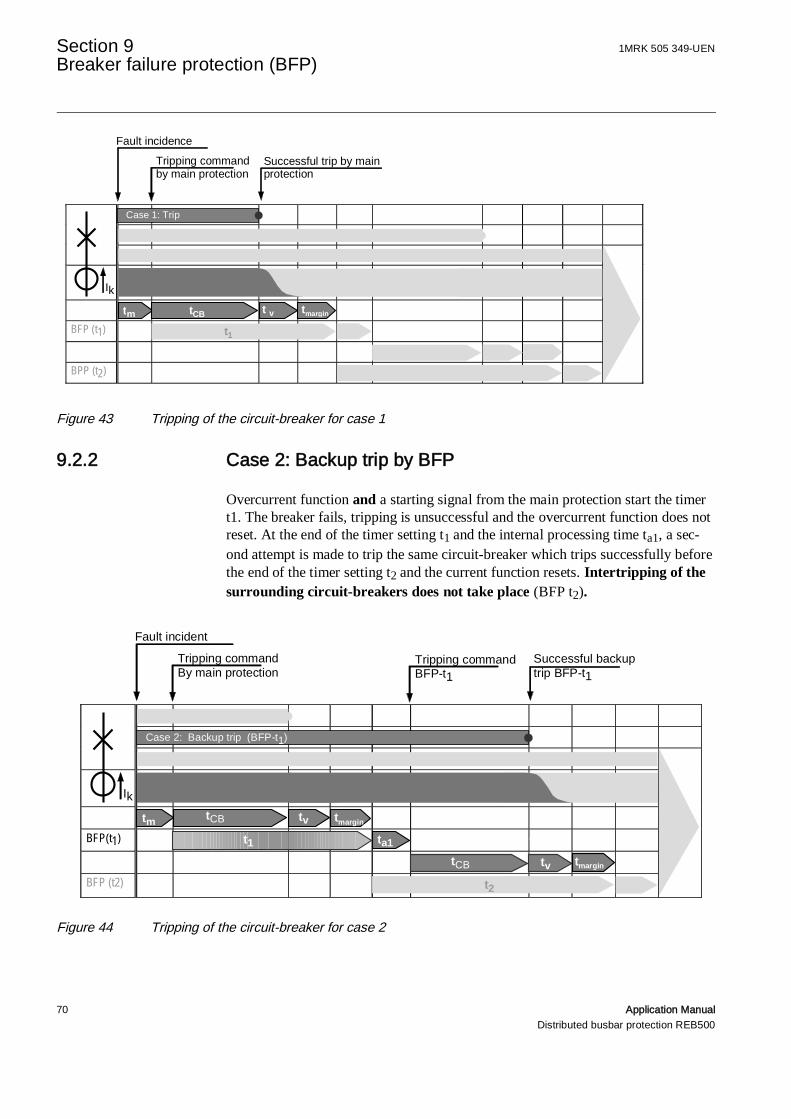
Section 9 1MRK 505 349-UENBreaker failure protection (BFP)
70 Application ManualDistributed busbar protection REB500
Figure 43 Tripping of the circuit-breaker for case 1
9.2.2 Case 2: Backup trip by BFP
Overcurrent function and a starting signal from the main protection start the timert1. The breaker fails, tripping is unsuccessful and the overcurrent function does notreset. At the end of the timer setting t1 and the internal processing time ta1, a sec-ond attempt is made to trip the same circuit-breaker which trips successfully beforethe end of the timer setting t2 and the current function resets. Intertripping of thesurrounding circuit-breakers does not take place (BFP t2).
Figure 44 Tripping of the circuit-breaker for case 2
BFP (t1)
BPP (t2)
Fault incidence
Case 1: Trip
Successful trip by mainprotection
Tripping commandby main protection
Ik
ta1
tCB
tm tmargintCB t v
t1
BFP(t1)
BFP (t2)
Fault incident
Successful backuptrip BFP-t1
Tripping commandBy main protection
Tripping commandBFP-t1
Case 2: Backup trip (BFP-t1)
Ik
tm tmargin
t1 ta1ta1
tCB tv tmargin
t2
tvtCB
tCB

1MRK 505 349-UEN Section 9Breaker failure protection (BFP)
Application Manual 71Distributed busbar protection REB500
9.2.3 Case 3: Intertripping of surrounding circuit-breakers byBFP
Overcurrent function and a starting signal from the main protection start the timert1. The breaker fails, tripping and backup tripping are unsuccessful and the over-current function does not reset. At the end of the timer settings t1 + t2 and the inter-nal processing time ta2 intertripping of the surrounding circuit-breakers takes placeto isolate the fault.
Figure 45 Intertripping of the circuit-breaker for case 3
Remote tripping of the opposite end of the line can be configured to take place atthe end of time t1 or the end of time t2.The settings of timers t1 and t2 can be determined according to the examples ofCases 1 and 2 above.
9.2.4 Timer t1 setting
To avoid any risk of a premature tripping command by BFP, the minimum settingof the timer t1 must be longer than the maximum time required for a successfulmain protection trip plus the maximum reset time of the overcurrent function.
> + +
As an example, the minimum setting for t1 for a circuit-breaker operating time (tCB)of 40 ms would be
> 40ms + 19ms + 20ms = 79ms
BPF (t1)
BFP (t2) ta1
Case 3: Intertripping (BFP t2)
Fault incidence
Tripping commandBFP-t2
Tripping commandby main protection
Tripping commandBFP-t1
Inter-tripping
Ik
tm tmargin
t1 ta1ta1
tCB tv tmargin
t2 ta2
tvtCB
tCB
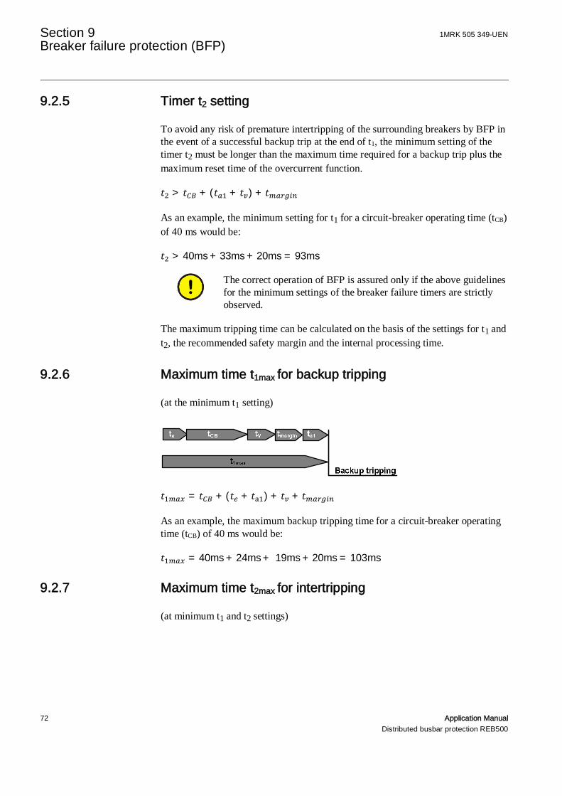
Section 9 1MRK 505 349-UENBreaker failure protection (BFP)
72 Application ManualDistributed busbar protection REB500
9.2.5 Timer t2 setting
To avoid any risk of premature intertripping of the surrounding breakers by BFP inthe event of a successful backup trip at the end of t1, the minimum setting of thetimer t2 must be longer than the maximum time required for a backup trip plus themaximum reset time of the overcurrent function.
> + ( + ) +
As an example, the minimum setting for t1 for a circuit-breaker operating time (tCB)of 40 ms would be:
> 40ms + 33ms + 20ms = 93ms
The correct operation of BFP is assured only if the above guidelinesfor the minimum settings of the breaker failure timers are strictlyobserved.
The maximum tripping time can be calculated on the basis of the settings for t1 andt2, the recommended safety margin and the internal processing time.
9.2.6 Maximum time t1max for backup tripping
(at the minimum t1 setting)
= + ( + ) + +
As an example, the maximum backup tripping time for a circuit-breaker operatingtime (tCB) of 40 ms would be:
= 40ms + 24ms + 19ms + 20ms = 103ms
9.2.7 Maximum time t2max for intertripping
(at minimum t1 and t2 settings)

1MRK 505 349-UEN Section 9Breaker failure protection (BFP)
Application Manual 73Distributed busbar protection REB500
= ( + + ) + 2 ∗ ( + + )
As an example, the maximum intertripping time for a circuit-breaker operatingtime (tCB) of 40 ms would be:
= 46ms + 2 ⋅ (40ms + 19ms + 20ms) = 204ms
9.3 Logic type
The internal BFP can be changed for special applications. The BFP scheme de-scribed here is the logic-type 1.
Alternative logics are:
2. Reserved for special applications, no description available.3. BFP can also be started by the tripping signals from the time-overcurrent and
breaker pole discrepancy protections. Otherwise logic type 3 corresponds totype 1.
4. The signals “13760_Start BFP L1L2L3_5” and “13765_Start BFP L1L2L3_6”initiate intertripping after BFP t1 irrespective of the setting for BFP t2. Other-wise logic type 4 corresponds to type 1.
9.4 BFP L0 system
In stations with a bypass bus, the behavior with enabled BFP L0 system remainsthe same as phase system.
The behavior of the trip redirection remains the same.
9.4.1 Current setting BFP L0
The current setting for the BFP L0 system may be well below loadcurrents. If any measured neutral current exceeds the setting while aL0 starting input is active after time t1 has passed, the BFP L0 sys-tem will issue a three phase trip.
There are three options to obtain a neutral current 3I0 for the BFP L0 system :
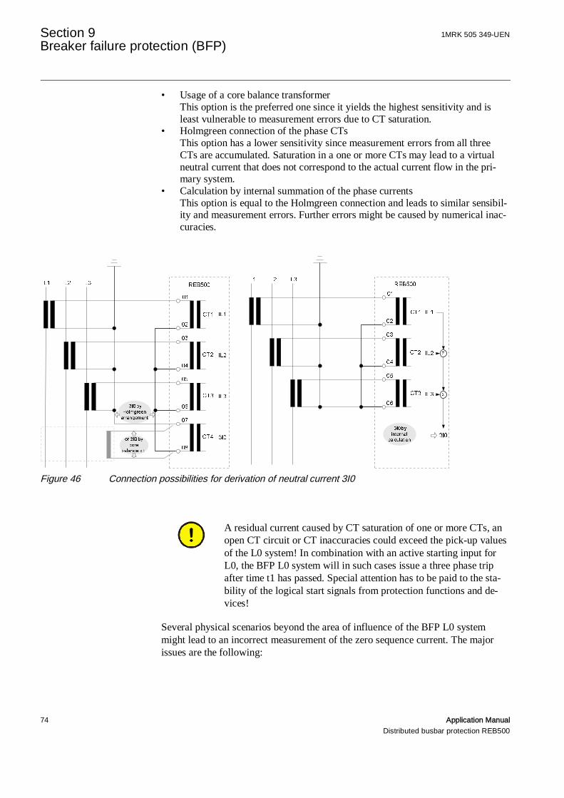
Section 9 1MRK 505 349-UENBreaker failure protection (BFP)
74 Application ManualDistributed busbar protection REB500
• Usage of a core balance transformerThis option is the preferred one since it yields the highest sensitivity and isleast vulnerable to measurement errors due to CT saturation.
• Holmgreen connection of the phase CTsThis option has a lower sensitivity since measurement errors from all threeCTs are accumulated. Saturation in a one or more CTs may lead to a virtualneutral current that does not correspond to the actual current flow in the pri-mary system.
• Calculation by internal summation of the phase currentsThis option is equal to the Holmgreen connection and leads to similar sensibil-ity and measurement errors. Further errors might be caused by numerical inac-curacies.
Figure 46 Connection possibilities for derivation of neutral current 3I0
A residual current caused by CT saturation of one or more CTs, anopen CT circuit or CT inaccuracies could exceed the pick-up valuesof the L0 system! In combination with an active starting input forL0, the BFP L0 system will in such cases issue a three phase tripafter time t1 has passed. Special attention has to be paid to the sta-bility of the logical start signals from protection functions and de-vices!
Several physical scenarios beyond the area of influence of the BFP L0 systemmight lead to an incorrect measurement of the zero sequence current. The majorissues are the following:

1MRK 505 349-UEN Section 9Breaker failure protection (BFP)
Application Manual 75Distributed busbar protection REB500
9.4.1.1 Neutral current I0 caused by CT saturation
In case one or more CTs saturate, the summation of the three phase currents willnot lead to a correct representation of the residual current in the primary system:
Figure 46 I0 in case of CT saturation
9.4.1.2 Neutral current I0 caused by an open CT circuit
If a connection to the CT is broken or interrupted, the BU is not able to measure thephase current and the summation of the phase currents will lead to an incorrectneutral current. In a symmetrical load situation, the calculated current will equalthe missing phase:
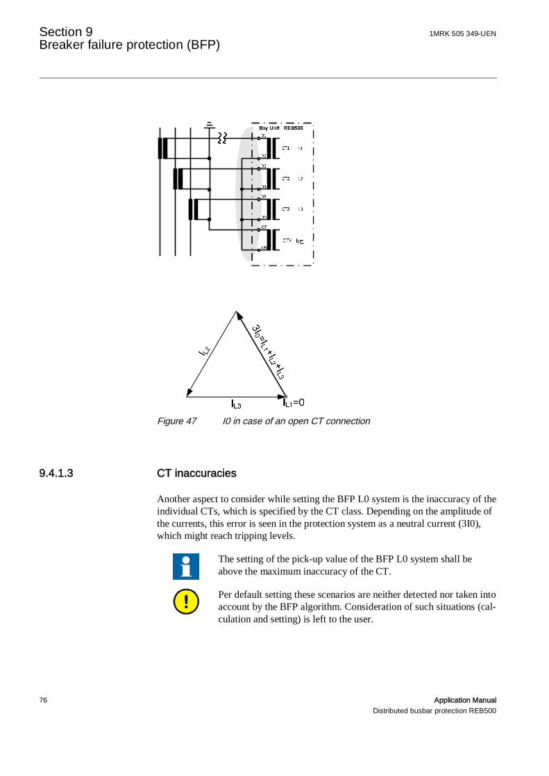
Section 9 1MRK 505 349-UENBreaker failure protection (BFP)
76 Application ManualDistributed busbar protection REB500
Figure 47 I0 in case of an open CT connection
9.4.1.3 CT inaccuracies
Another aspect to consider while setting the BFP L0 system is the inaccuracy of theindividual CTs, which is specified by the CT class. Depending on the amplitude ofthe currents, this error is seen in the protection system as a neutral current (3I0),which might reach tripping levels.
The setting of the pick-up value of the BFP L0 system shall beabove the maximum inaccuracy of the CT.
Per default setting these scenarios are neither detected nor taken intoaccount by the BFP algorithm. Consideration of such situations (cal-culation and setting) is left to the user.
1MRK 505 349-UEN Section 9Breaker failure protection (BFP)
Application Manual 77Distributed busbar protection REB500
The signal 23340_BFP TRIP L0 is available as an input to bay pro-tection functions. Further measures to ensure selective trippingcan be achieved by logically releasing the trip signal with additionalbay protection functions.
9.4.2 Time grading for BFP L0 system
The time grading characteristics for BFP L0 system is identical to the phase sys-tem. Different settings for BFP phase and neutral system are possible.
Since the time setting for phase faults and ground faults can be dif-ferent, the time grading (and setting) has to be done for both theBFP phase and BFP neutral system separately.
Setting the timer t1-L0 below the timer t1 is usually not necessary and not recom-mended. Deviations from this guideline have to be verified by a detailed settingcalculation.
9.5 External start of BFP
The timers of BFP can also be started independently of the overcurrent check andthe main protection inputs via an external input.
For safety reasons, a normally-open auxiliary contact on the circuit-breaker should be connected in series with the external control sig-nal applied to this input.
9.6 BFP setting “Active for CB open”
The breaker failure function includes the setting “Active for CB open”. If this set-ting is enabled, the timers t1 and t2 are started independent from the circuit-breakerposition (this is the factory configuration).
If “Active for CB open” is disabled, the timers t1 and t2 are not started when thecircuit-breaker is open, i.e. the breaker failure function is disabled.
The setting “Active for CB open” function is determined by ABBwhen engineering the system and cannot be changed subsequently.Where breaker failure shall be disabled when circuit-breaker is openthis setting has to be defined when system is initially engineered.

Section 10 1MRK 505 349-UENAdditional protection features
78 Application ManualDistributed busbar protection REB500
Section 10 Additional protection features
10.1 Enabling tripping commands
10.1.1 Example 1: BBP function tripping enabled by externalundervoltage relay
10.1.1.1 Problem
In a solidly grounded power system, tripping by the BBP has to be interlocked byan external undervoltage criterion. Every protection zone is correspondinglyequipped with a VT and undervoltage function.
Figure 48 Examples 1, 3 and 5: BBP enable
10.1.1.2 Solution
The enabling signals from the external undervoltage relays are connected to therespective “31805_External release BB zone” input signal.

1MRK 505 349-UEN Section 10Additional protection features
Application Manual 79Distributed busbar protection REB500
Figure 49 Settings for example 1
10.1.1.3 Result
In the event of a fault on a given busbar section (e.g. BB1), the busbar protectionfunction for BB1 trips, but the tripping signal has to wait for the enabling signal forBB1. A fault on a busbar section will normally cause a voltage collapse, which isdetected by the external undervoltage relay for BB1. The undervoltage relay thusalso trips and transmits its enabling signal to REB500. REB500 then trips all thefeeders connected to busbar section 1.
10.1.2 Example 2: EFP function tripping enabled by the internalundervoltage function
10.1.2.1 Problem
In a solidly grounded power system, transfer tripping by the EFP has to be inter-locked by the internal undervoltage function.
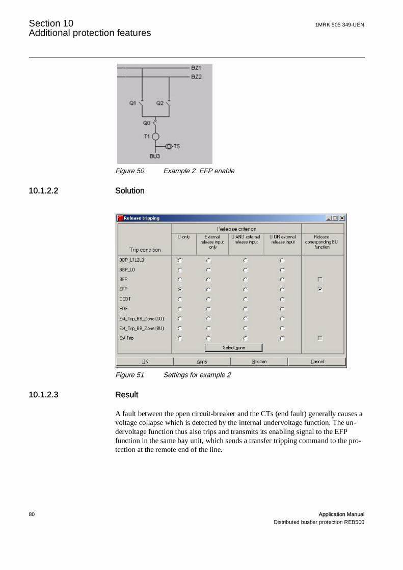
Section 10 1MRK 505 349-UENAdditional protection features
80 Application ManualDistributed busbar protection REB500
Figure 50 Example 2: EFP enable
10.1.2.2 Solution
Figure 51 Settings for example 2
10.1.2.3 Result
A fault between the open circuit-breaker and the CTs (end fault) generally causes avoltage collapse which is detected by the internal undervoltage function. The un-dervoltage function thus also trips and transmits its enabling signal to the EFPfunction in the same bay unit, which sends a transfer tripping command to the pro-tection at the remote end of the line.

1MRK 505 349-UEN Section 10Additional protection features
Application Manual 81Distributed busbar protection REB500
10.1.3 Example 3: BBP tripping enabled by the internalundervoltage function
10.1.3.1 Problem
In a solidly grounded power system, tripping by the BBP has to be interlocked bythe internal undervoltage criterion. Every protection zone is correspondinglyequipped with a VT and undervoltage function.
10.1.3.2 Solution
Figure 52 Settings for examples 3 and 4
10.1.3.3 Result
In the event of a fault on a given busbar section (e.g. BB1), the busbar protectionfunction for BB1 trips. A fault on a busbar section will normally cause a voltagecollapse, which is detected by the internal undervoltage function for BB1. The un-dervoltage function thus also trips and transmits a signal to enable tripping of BB1.REB500 then trips all the feeders connected to busbar section 1.

Section 10 1MRK 505 349-UENAdditional protection features
82 Application ManualDistributed busbar protection REB500
10.1.4 Example 4: BBP function tripping enabled by the internalundervoltage function without VTs on the busbars
10.1.4.1 Problem
In a solidly grounded power system, tripping by the BBP has to be interlocked bythe internal undervoltage criterion, but there are no VTs to measure the voltage onthe busbars.
Figure 53 Example 4: Enabling tripping by the BBP function without VTs onthe busbars
10.1.4.2 Solution
The settings are the same as in example 3.
REB500 evaluates all the VTs assigned to the respective protection zone (see Tech-nical Manual). Assignment takes place via the intertripping logic, i.e. it depends onthe statuses of the isolators. Tripping is only enabled when all the voltage functionsassigned to the protection zone in question generate an enabling signal (ANDlogic).
This means that an overvoltage function cannot enable tripping of the protectionzone should the voltage be interrupted either due to a tripped m.c.b. or an open-circuit.
This means that an undervoltage function will enable tripping of the protectionzone should the voltage be interrupted either due to a tripped m.c.b. or an open-

1MRK 505 349-UEN Section 10Additional protection features
Application Manual 83Distributed busbar protection REB500
circuit. Since, however, the other undervoltage functions assigned to the protectionzone are also evaluated; they prevent tripping from taking place.
An interruption of the VT circuit can be detected in the case of anundervoltage function by supervising the bay unit output signal“28805_Voltage criterion” or the central unit output signal“48805_Voltage criterion”.
By activating the input signal “18205_Fuse failure superv. UV” atripped m.c.b. can be configured to enable tripping of the respectiveprotection zone in the case of an overvoltage function.
REB500 is thus able derive the voltage on the busbars, even if there are no VTs tomeasure it directly. Tripping of a protection zone to which no VTs are assigned(e.g. all the isolators open) is enabled by the voltage function.
10.1.4.3 Result
In the event of a fault on a given busbar section (e.g. BB1), the busbar protectionfunction for BB1 trips. A fault on a busbar section will normally cause a voltagecollapse, which in this case is detected by all the undervoltage functions in all thebay units assigned to BB1. Since for all of them the release criterion is fulfilled,intertripping is enabled and REB500 isolates BB1.
10.1.5 Example 5: BBP neutral measuring system enabled by theinternal undervoltage function
10.1.5.1 Problem
In stations in which the maximum load current of some feeders can exceed theminimum fault current of the protection zones (e.g. ground fault in impedancegrounded power systems), an interrupted CT circuit can cause a differential currenthigher than the setting of the current comparison circuit.
10.1.5.2 Solution
To guard against this, the internal REB500 undervoltage function can be config-ured as an additional neutral current criterion for the BBP function.

Section 10 1MRK 505 349-UENAdditional protection features
84 Application ManualDistributed busbar protection REB500
Figure 54 Settings for example 5
10.1.5.3 Result
In the event of a ground fault on a given busbar section (e.g. BB1), the neutralmeasuring system for BB1 trips. A ground fault on a busbar section will normallycause a voltage collapse, which is detected by the internal undervoltage functionfor BB1. REB500 then isolates BB1.

1MRK 505 349-UEN Section 11 1½ breaker schemes and duplex stations
Application Manual 85Distributed busbar protection REB500
Section 11 1½ breaker schemes and duplex stations
This section describes the application of the busbar, breaker failure and end faultprotection functions in 1½ breaker schemes and duplex stations. The description isbased on typical station layouts.
1½ breaker schemes can be divided into five main groups (versions 1 to 5) whichhave to be considered separately from the point of view of discrimination, alongwith one version for the application of REB500 to duplex stations:
1. 1½ breaker scheme with 3 CTs per diameter2. 1½ breaker scheme with 6 CTs per diameter3. 1½ breaker scheme with 5 CTs per diameter4. 1½ breaker scheme with 8 CTs per diameter5. 1½ breaker scheme with BBP only6. Duplex stations
Table 7 lists the characteristics of these 6 versions (* indicates that the characteris-tic is not relevant to REB500).
Table 7 1 ½ breaker scheme groups and duplex stationsCharacteristic 1 2 3 4 5 6Number of CTs 3 6 5 8 * 2Number of REB500 BUs 3 3 5 8 2 2Number of REB500 BFP functions 3 3 3 3 0 2Number of REB500 EFP functions 3 0 3 0 0 2Number of T-zones protected by REB500 1 1 2 2 0 2Number of Bay protection devices (LP, TP) 2 2 2 2 * 2Incidence high high mid low mid low
One advantage of REB500 in the case of a 1½ breaker scheme is that the so-calledT zone is fully protected.
The T zone is the section of busbar between the CTs plus the line T up to the openline isolator. The bay protection (distance protection) does not detect faults in thiszone correctly, because the voltage measured is the wrong one (open line isolator).
This zone is normally protected by an overcurrent function included in the line pro-tection. This reacts, however, to CT saturation during through-faults (e.g. busbarfaults) and could mal-operate.

Section 11 1MRK 505 349-UEN1½ breaker schemes and duplex stations
86 Application ManualDistributed busbar protection REB500
REB500 uses its current restrained differential protection and phase comparisonfunctions to protect this zone. The corresponding algorithm operates discriminatelyeven if CTs saturate.
Busbar protection systems are generally used to discriminatively protect main bus-bars. In addition to this, however, REB500 is also able to effectively protect the Tzone of a 1½ breaker scheme, because it creates an image of the topology of theentire station with up to 32 independent protection zones, each processed by thebusbar protection algorithms (current restrained differential and phase comparisonprotection).
For REB500 to protect the T zone, its image of the station must include all thecomponents of the 1½ breaker scheme (circuit-breakers, CTs and line isolator).
The same applies when applying the breaker failure and end fault options.
The T zone protection relies on the image of the station to measure (current re-strained differential and phase comparison) at the correct points and to intertrip thecorrect breakers after it has detected an internal fault (both breakers limiting the Tzone).
The breaker failure and end fault functions use the REB500 image of the station tointertrip the correct breakers, respectively to transfer trip the correct remote breaker(tripping signal to the re-mote end of a line, i.e. signal 21115_REMOTE TRIP).
In the reverse direction, transfer trip signals from the remote end of a line are dis-tributed to the bay units of the appropriate feeders (signal 11105_External TRIP).An active “External trip” input signal trips the circuit-breakers limiting the T zonevia the REB500 tripping contacts and starts the appropriate breaker failure func-tion.
In the following explanations and figures, LP refers to line protection (e.g. distanceprotection) and TP to transformer protection (e.g. differential protection).

1MRK 505 349-UEN Section 11 1½ breaker schemes and duplex stations
Application Manual 87Distributed busbar protection REB500
11.1 1½ breaker scheme with 3 CTs per diameter
Figure 55 T-Zone protection, version 1
11.1.1 T zone protection with isolator Q6 closed
When the line isolator Q6 is closed, faults in the T zones (X and Y) are detectedand tripped by the feeder protection (line protection or transformer protection). TheT zones are considered to be part of the line or the transformer feeder.
11.1.2 T zone protection with isolator Q6 open
11.1.2.1 Line
If the VT on A1 is on the line side of the isolator Q6, the distance protection is una-ble to protect the T zone (X) when the isolator Q6 is open, because the voltage itneeds for measurement is either missing or wrong.
In conventional systems an overcurrent function activated by the isolator status sig-nal Q6 protects the T zone.
In stations equipped with REB500, there is the possibility of it taking over the pro-tection of the T zone. To this end, the status signal for isolator Q6 is connected tothe bay unit (BU1) and when the isolator is open, a measuring system specificallyfor the T zone (X) is activated in REB500. As in the case of the main busbars,measurement is based on the current restrained differential and phase comparisonbusbar protection algorithms, which are considerably more stable during through-faults with CT saturation than overcurrent protection and therefore to be preferred.
S1 S2X Y
A1 A2
Q6
BU1
BU2
BU3
LP TP
Q6
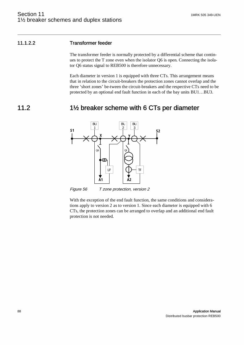
Section 11 1MRK 505 349-UEN1½ breaker schemes and duplex stations
88 Application ManualDistributed busbar protection REB500
11.1.2.2 Transformer feeder
The transformer feeder is normally protected by a differential scheme that contin-ues to protect the T zone even when the isolator Q6 is open. Connecting the isola-tor Q6 status signal to REB500 is therefore unnecessary.
Each diameter in version 1 is equipped with three CTs. This arrangement meansthat in relation to the circuit-breakers the protection zones cannot overlap and thethree ‘short zones’ be-tween the circuit-breakers and the respective CTs need to beprotected by an optional end fault function in each of the bay units BU1…BU3.
11.2 1½ breaker scheme with 6 CTs per diameter
Figure 56 T zone protection, version 2
With the exception of the end fault function, the same conditions and considera-tions apply to version 2 as to version 1. Since each diameter is equipped with 6CTs, the protection zones can be arranged to overlap and an additional end faultprotection is not needed.
S1 S2X Y
A1 A2
Q6
BU1
BU2
BU3
LP TP
Q6
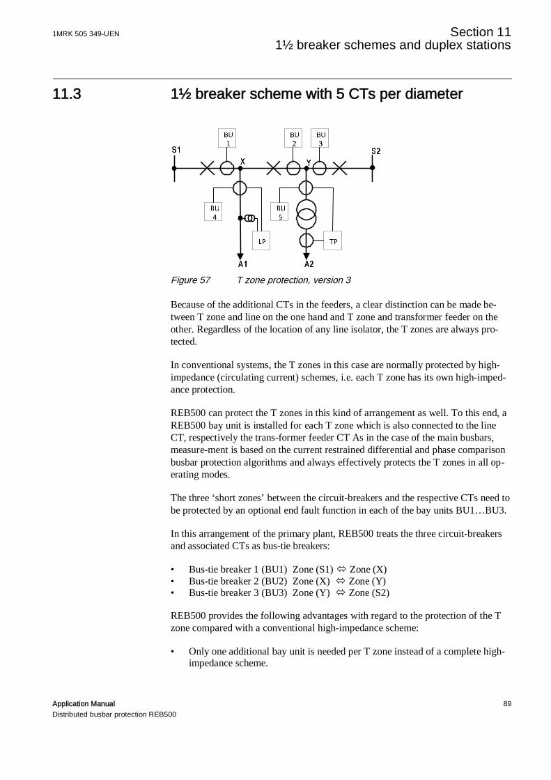
1MRK 505 349-UEN Section 11 1½ breaker schemes and duplex stations
Application Manual 89Distributed busbar protection REB500
11.3 1½ breaker scheme with 5 CTs per diameter
Figure 57 T zone protection, version 3
Because of the additional CTs in the feeders, a clear distinction can be made be-tween T zone and line on the one hand and T zone and transformer feeder on theother. Regardless of the location of any line isolator, the T zones are always pro-tected.
In conventional systems, the T zones in this case are normally protected by high-impedance (circulating current) schemes, i.e. each T zone has its own high-imped-ance protection.
REB500 can protect the T zones in this kind of arrangement as well. To this end, aREB500 bay unit is installed for each T zone which is also connected to the lineCT, respectively the trans-former feeder CT As in the case of the main busbars,measure-ment is based on the current restrained differential and phase comparisonbusbar protection algorithms and always effectively protects the T zones in all op-erating modes.
The three ‘short zones’ between the circuit-breakers and the respective CTs need tobe protected by an optional end fault function in each of the bay units BU1…BU3.
In this arrangement of the primary plant, REB500 treats the three circuit-breakersand associated CTs as bus-tie breakers:
• Bus-tie breaker 1 (BU1) Zone (S1)ó Zone (X)• Bus-tie breaker 2 (BU2) Zone (X) ó Zone (Y)• Bus-tie breaker 3 (BU3) Zone (Y) ó Zone (S2)
REB500 provides the following advantages with regard to the protection of the Tzone compared with a conventional high-impedance scheme:
• Only one additional bay unit is needed per T zone instead of a complete high-impedance scheme.
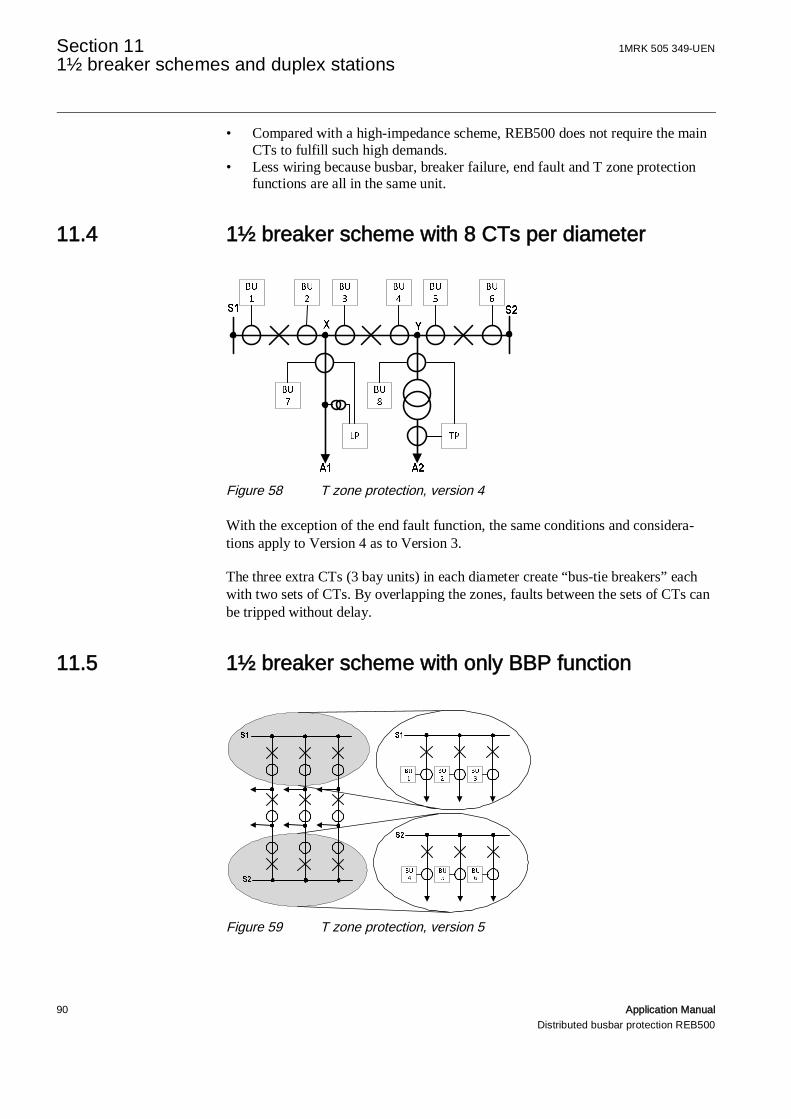
Section 11 1MRK 505 349-UEN1½ breaker schemes and duplex stations
90 Application ManualDistributed busbar protection REB500
• Compared with a high-impedance scheme, REB500 does not require the mainCTs to fulfill such high demands.
• Less wiring because busbar, breaker failure, end fault and T zone protectionfunctions are all in the same unit.
11.4 1½ breaker scheme with 8 CTs per diameter
Figure 58 T zone protection, version 4
With the exception of the end fault function, the same conditions and considera-tions apply to Version 4 as to Version 3.
The three extra CTs (3 bay units) in each diameter create “bus-tie breakers” eachwith two sets of CTs. By overlapping the zones, faults between the sets of CTs canbe tripped without delay.
11.5 1½ breaker scheme with only BBP function
Figure 59 T zone protection, version 5
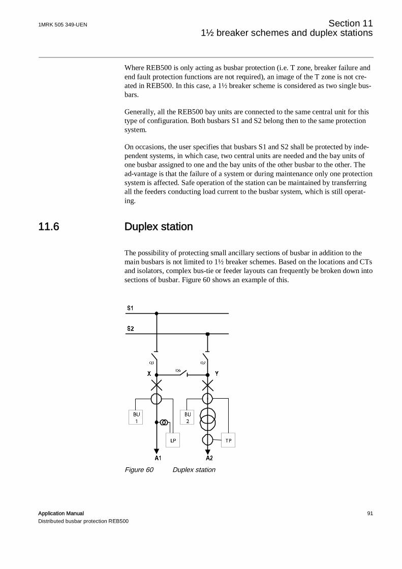
1MRK 505 349-UEN Section 11 1½ breaker schemes and duplex stations
Application Manual 91Distributed busbar protection REB500
Where REB500 is only acting as busbar protection (i.e. T zone, breaker failure andend fault protection functions are not required), an image of the T zone is not cre-ated in REB500. In this case, a 1½ breaker scheme is considered as two single bus-bars.
Generally, all the REB500 bay units are connected to the same central unit for thistype of configuration. Both busbars S1 and S2 belong then to the same protectionsystem.
On occasions, the user specifies that busbars S1 and S2 shall be protected by inde-pendent systems, in which case, two central units are needed and the bay units ofone busbar assigned to one and the bay units of the other busbar to the other. Thead-vantage is that the failure of a system or during maintenance only one protectionsystem is affected. Safe operation of the station can be maintained by transferringall the feeders conducting load current to the busbar system, which is still operat-ing.
11.6 Duplex station
The possibility of protecting small ancillary sections of busbar in addition to themain busbars is not limited to 1½ breaker schemes. Based on the locations and CTsand isolators, complex bus-tie or feeder layouts can frequently be broken down intosections of busbar. Figure 60 shows an example of this.
Figure 60 Duplex station

Section 11 1MRK 505 349-UEN1½ breaker schemes and duplex stations
92 Application ManualDistributed busbar protection REB500
Those busbar protection measuring systems are activated in REB500 that areneeded to reflect the prevailing operating conditions (isolator statuses).
Table 8 Measuring systems in duplex stationsQ1 Q2 Q6 Measuring system 1 Measuring system 2 Measuring system 3● ● ○ S1//X S2//Y● ● ● S1// X//Y//S2● ○ ● S1//X//Y S2○ ● ● S1 S2//X//Y○ ○ ● S1 S2 X//Y
The symbol // indicates measuring systems determined by the isolator statuseswhich are linked to form a single measuring system, e.g. X//Y
For operating mode 5, the feeder isolators Q1 and Q2 are open and isolator Q6 isclosed and therefore a single measuring system X//Y is formed that discrimina-tively protects zone X-Y.
11.7 Assignment of bay units
The number of bay units needed in a particular station is in most cases the greaterof the total number of circuit-breakers or the total number of CTs in the REB500image.
The example below shows the assignment of bays to bay units based on version 1of the T zone protection. The two feeder bays which contain neither circuit-break-ers nor CTs are each assigned to the bay unit for the CT and circuit-breaker goingto the busbar on their side. The circuit-breaker and CT in the center are assigned toa bay unit of their own.
If there are CTs in the feeders or on both sides of the circuit-breakers and these areincluded in the busbar protection, the number of bay units needed increases in ac-cordance with the above relationship.

1MRK 505 349-UEN Section 11 1½ breaker schemes and duplex stations
Application Manual 93Distributed busbar protection REB500
Figure 61 Assignment of bay units

Section 12 1MRK 505 349-UENComplex stations
94 Application ManualDistributed busbar protection REB500
Section 12 Complex stations
In practice, complex bus-tie arrangements are frequently necessary to meet all therequirements with respect to reliability of supply and switching adaptability to suitoperating circumstances.
12.1 BBP and BFP in stations with a bypass busbar
If the breaker failure function in BU1 is started by an external device when operat-ing via the bypass busbar, the entire busbar 2 is tripped instead of just circuit-breaker Q9.
This can be prevented if circuit-breaker Q9 in BU2 is equipped with its own CT,thus enabling an additional protection zone to be defined for the busbar protection.
Figure 62 Operation via a bypass busbar
12.2 Busbars with “bus-ties” in series
The term “series tie” is used when referring to the connection of busbars or busbarsections via two or more bus-tie breakers in series. A typical example of a series tieis a 1½ breaker scheme. In an arrangement of this kind, each circuit-breaker/CTpair is treated as a bus-tie breaker (bus-tie A S1-Sx , bus-tie B Sx-Sy , bus-tie CSy-S2). When all three breakers are closed, busbars S1 and S2 are connected via a“series tie” A-B-C.
Q0 BypassBusbar
BU1 BU2
Q9
Busbar 2Busbar 1

1MRK 505 349-UEN Section 12Complex stations
Application Manual 95Distributed busbar protection REB500
Providing all the feeders are part of a 1½ breaker scheme, the necessity to block abus-tie breaker when there is a parallel connection between the busbars as dis-cussed previously is irrelevant, because there are no feeders with isolators to eachof the main busbars and therefore no possibility of the 1½ breaker diameters beingparalleled.
Figure 63 1 ½ breaker scheme
Figure 64 1½ breaker scheme with parallel connection between the busbars
In a mixed system, the response of the system with respect to the parallel connec-tion has to be considered.
When there is a parallel connection between the busbars (Q1 and Q2 closed), thebusbar protection measuring systems S1 and S2 are combined to form a singlemeasuring system (S1/S2).
Assuming the three circuit-breakers of the diameter are closed, the current of a bus-bar fault (Ik1) divides into a direct portion (Ik11) and a portion via the series tie A-

Section 12 1MRK 505 349-UENComplex stations
96 Application ManualDistributed busbar protection REB500
B-C (Ik12). The T zone feeders Sx and Sy can also make fault current contribu-tions (Ik2) and (Ik3). In relation to the main busbars (S1 and S2) in parallel, thecurrent (Ik12) flows out through bus-tie C and back through bus-tie A. For a faulton the busbars, the combined measuring system (S1/S2) is thus presented with twoopposing current vectors indicating an external fault and the phase comparisonblocks tripping.
To overcome this possibility, REB500 has a special blocking logic which can beconfigured for series ties. This consists in defining the starting and finishing pointsof series ties and not evaluating measurements between them when both are in thesame measuring zone.
In the example shown, the starting point (busbar connection to bus-tie A) and thefinishing point (busbar connection to bus-tie C) belong to the same measuring zone(S1/S2) and therefore the measurements of the three bus-tie breakers A, B and Care not evaluated.
In normal operation, i.e. when the main busbars are not in parallel, the two T zonesSx and Sy treated discriminatively as independent protection zones. When the bus-bars are paralleled and the series ties excluded from evaluation, the feeder currents(Ik2 and Ik3) are still measured, but not those into and out of the two T zonesthrough their respective bus-ties. The T zone measurements are therefore invalid.For this reason, not only are the measurements of the series tie excluded from eval-uation, but in addition the diameter CTs are short-circuited. This means that thetwo T zones Sx and Sy are connected to the main busbars S1/S2 and a measuringzone S1/Sx/Sy/S2 is created, which correctly includes the two feeder currents (Ik2,Ik3).
Application of the extended bus-tie blocking logic is only possible providing thefeeders in the T zones are equipped with protection CT cores connected to REB500bay units.
It can only be configured for a bus-tie breaker during initial engineering of the sys-tem. By opening the HMI500 “Configuration” menu and selecting “Circuit-break-ers”, it is possible to see whether the logic is active for a particular bus-tie breakeror not, but the setting cannot be changed.
Figure 65 Status of the bus-tie blocking logic

1MRK 505 349-UEN Section 12Complex stations
Application Manual 97Distributed busbar protection REB500
Figure 66 shows a reduced 1½ breaker scheme. With the additional bus-tie logic,the measurements of bus-ties A and B are excluded from evaluation and their CTsshort-circuited while the main busbars S1 and S2 are connected in parallel (Q1 andQ2 closed). A combined measuring zone S1/Sx/S2 is created in which all faults arecorrectly detected.
Figure 67 shows a multiple busbar configuration in which the bus-ties A and Bcount as series ties from the point of view of busbars S1 and S3. With the addi-tional bus-tie logic, the measurements of bus-ties A and B are excluded from evalu-ation and their CTs short-circuited while the main busbars S1 and S3 are connectedin parallel (Q1 and Q3 closed). A combined measur-ing zone S1/S2/S3 is created inwhich all faults are correctly de-tected. A drawback, however, is that discrimina-tion is lost for busbar S2 while S1 and S3 are in parallel.
Figure 66 Reduced 1½ breaker scheme with parallel connection between thebusbars
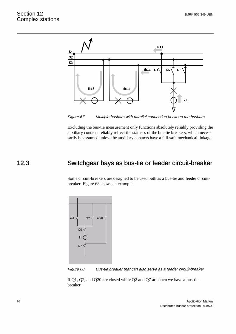
Section 12 1MRK 505 349-UENComplex stations
98 Application ManualDistributed busbar protection REB500
Figure 67 Multiple busbars with parallel connection between the busbars
Excluding the bus-tie measurement only functions absolutely reliably providing theauxiliary contacts reliably reflect the statuses of the bus-tie breakers, which neces-sarily be assumed unless the auxiliary contacts have a fail-safe mechanical linkage.
12.3 Switchgear bays as bus-tie or feeder circuit-breaker
Some circuit-breakers are designed to be used both as a bus-tie and feeder circuit-breaker. Figure 68 shows an example.
Figure 68 Bus-tie breaker that can also serve as a feeder circuit-breaker
If Q1, Q2, and Q20 are closed while Q2 and Q7 are open we have a bus-tiebreaker.

1MRK 505 349-UEN Section 12Complex stations
Application Manual 99Distributed busbar protection REB500
If Q1 or Q2, and Q0 and Q7 are closed, while Q20 is open, we have a feeder cir-cuit-breaker.
Exclusion of the measurement of one or both protection zones is made selectivewhen engineering the system, i.e. the one that is not excluded remains active.
12.4 Control using “11105_External TRIP”
This signal is generated when an external protection device trips (including one inthe remote station) and isolates fault on transmission lines or transformer feedersby operating the REB500 tripping contact.
On normal feeders, the “External TRIP” signal only trips the circuit-breaker of therespective feeder. Its effect for special configurations is as follows:
12.4.1 1½ breaker scheme
Both circuit-breakers controlling the feeder are tripped.
12.4.2 Bypass mode
An “External TRIP” signal applied to circuit-breaker Q0 controlling Feeder 1 doesnot isolate the fault when isolator Q7 is closed (bypass mode). For this reason, cir-cuit-breaker Q0 controlling Coupler 2 is automatically opened. Through-faults cannow be correctly tripped.

Section 12 1MRK 505 349-UENComplex stations
100 Application ManualDistributed busbar protection REB500
Figure 69 Bypass busbar
12.4.3 Bypass isolator
The “External TRIP” signal trips circuit-breaker Q0 of Feeder 1, but the fault isstill not cleared because the bypass isolator Q7 is closed. The busbar protectionthen intertrips busbar 3 to finally clear the fault.
Figure 70 Bypass isolator


Contact us
ABB ABSubstation Automation ProductsSE-721 59 VästeråsSwedenTelephone: +46 (0) 21 32 50 00Facsimile: +46 (0) 21 14 69 18http://www.abb.com/substationautomation
1MR
K50
534
9-U
EN-
©C
opyr
ight
2016
AB
B,A
llrig
htsr
eser
ved.