discontinuous fibrous bouligand architecture enabling
TRANSCRIPT

Discontinuous fibrous Bouligand architecture enablingformidable fracture resistance with crackorientation insensitivityKaijin Wua, Zhaoqiang Songb, Shuaishuai Zhanga, Yong Nia,1, Shengqiang Caib, Xinglong Gonga, Linghui Hea,and Shu-Hong Yuc,d
aChinese Academy of Sciences Key Laboratory of Mechanical Behavior and Design of Materials, Department of Modern Mechanics, Chinese Academy ofSciences Center for Excellence in Complex System Mechanics, University of Science and Technology of China, Hefei, Anhui 230026, China; bDepartment ofMechanical and Aerospace Engineering, University of California San Diego, La Jolla, CA 92093; cDivision of Nanomaterials and Chemistry, Hefei NationalLaboratory for Physical Sciences at the Microscale, University of Science and Technology of China, Hefei, Anhui 230026, China; and dDepartment ofChemistry, Institute of Biomimetic Materials and Chemistry, University of Science and Technology of China, Hefei, Anhui 230026, China
Edited by David A. Weitz, Harvard University, Cambridge, MA, and approved May 28, 2020 (received for review January 12, 2020)
Bioinspired architectural design for composites with much higherfracture resistance than that of individual constituent remains amajor challenge for engineers and scientists. Inspired by thesurvival war between the mantis shrimps and abalones, we designa discontinuous fibrous Bouligand (DFB) architecture, a combina-tion of Bouligand and nacreous staggered structures. Systematicbending experiments for 3D-printed single-edge notched speci-mens with such architecture indicate that total energy dissipationsare insensitive to initial crack orientations and show optimizedvalues at critical pitch angles. Fracture mechanics analyses demon-strate that the hybrid toughening mechanisms of crack twistingand crack bridging mode arising from DFB architecture enable ex-cellent fracture resistance with crack orientation insensitivity. Thecompromise in competition of energy dissipations between cracktwisting and crack bridging is identified as the origin of maximumfracture energy at a critical pitch angle. We further illustrate thatthe optimized fracture energy can be achieved by tuning fractureenergy of crack bridging, pitch angles, fiber lengths, and twistangles distribution in DFB composites.
biomimetic design | fibrous composite | fracture resistance | tougheningmechanism | optimization strategies
Bioinspired structural designs attract intense interest inachieving remarkable fracture resistance in synthetic fibrous
composites (1–3), which provide enhanced fracture toughnesswell beyond their constituents by controlling crack propagationmodes dictated by internal architectures (4, 5). Typically, naturalfibrillar materials act as basic building reinforcements to createfracture-resistant materials through controlling fibrillar align-ments and orientations in three-dimensional (3D) assembly (6).Varying the arrangements can create materials with vastly dif-ferent macroscale mechanical properties (1, 2, 6, 7). One primeexample is the Bouligand architecture characterized by thestacking of fibrous layers rotated by a pitch angle in chitinnanofibrils-based natural materials (8–18), such as the exoskeletonof arthropods (e.g., crab, lobster, beetles, and shrimp) and mam-mal bone, etc. The dactyl club of mantis shrimp composed ofmineralized chitin nanofibrils lamellae organized in a twistedplywood (Bouligand) structure exhibits exceptional damage re-sistance (9, 11, 16, 17). In the survival war between mantis shrimpsand abalones (Fig. 1A), the abalones are often the prey of mantisshrimps, and in general, the “spear” of mantis shrimps armed withpowerful dactyl clubs can often shatter the “shield” of hard aba-lone (19). This is particularly intriguing because these abaloneshells composed of mineral crystals and protein matrix with“brick-and-mortar” arrangements (i.e., nacreous architecture) arethemselves considered a benchmark of supertough biocomposites(20–24). Given that both Bouligand and nacreous structures showconsiderable reinforcement, it is still elusive whether the
Bouligand structure in its “spear” plays important role in thecompetition of mantis shrimp as the winner or not. Recent studiesdemonstrated that when the arrangements of fibrils in crustaceancuticle change from the nacreous staggered structure with anorientation along the longitudinal axis to the Bouligand pattern,the anisotropic elasticity of the structure decreases monotonously(6, 25) (Fig. 1A). This motivates us that Bouligand-type arrange-ments may provide efficient ways to achieve excellent mechanicalperformances without fiber orientation dependence, which is asevere limit in unidirectional fibrous composites (6, 26).Recent investigations revealed that crack twisting mode sig-
nificantly enhances fracture toughness in the Bouligand archi-tecture where a crack plane propagates following the twistedfiber orientation (27–33). This amplifies the crack surface areaand reorients fibers orientation in response to external loadings(27–29, 33), e.g., tension, bending, or impact loads. The resultantmodulus oscillation in the Bouligand structure is also proposedto promote the crack twisting (30). For nacreous architectures,the crack bridging mode arising from the discontinuous platelets’pull-out and sliding in the crack front provides enhanced
Significance
Inspired by the survival war between the “spear” of mantisshrimps with Bouligand-type microstructures and the “shield”of abalone with nacreous staggered architectures, we designan architecture, a combination of Bouligand and nacreousstaggered structures, which enables excellent fracture re-sistance with crack orientation insensitivity. The sophisticatedhybrid fracture mode due to the competition of energy dissi-pations between crack twisting and crack bridging arising inDFB architecture is identified as the origin of maximum fractureenergy at a critical pitch angle. This finding sheds light on hownature evolves materials to exceptional fracture toughness andcrack orientation insensitivity. The provided design strategieswith parameters selection principle enable the fabrication offormidable fracture-resistant fibrous composite systems thatadapt to loads in various orientations.
Author contributions: Y.N. designed research; K.W., Z.S., S.Z., and Y.N. performed re-search; Y.N. contributed new reagents/analytic tools; K.W., Z.S., S.Z., Y.N., S.C., X.G.,L.H., and S.-H.Y. analyzed data; and K.W., Y.N., S.C., X.G., L.H., and S.-H.Y. wrotethe paper.
The authors declare no competing interest.
This article is a PNAS Direct Submission.
Published under the PNAS license.1To whom correspondence may be addressed. Email: [email protected].
This article contains supporting information online at https://www.pnas.org/lookup/suppl/doi:10.1073/pnas.2000639117/-/DCSupplemental.
First published June 22, 2020.
www.pnas.org/cgi/doi/10.1073/pnas.2000639117 PNAS | July 7, 2020 | vol. 117 | no. 27 | 15465–15472
ENGINEE
RING
BIOPH
YSICSAND
COMPU
TATIONALBIOLO
GY
Dow
nloa
ded
by g
uest
on
Janu
ary
1, 2
022

toughness (23, 24, 34, 35). Both bioinspired toughening mecha-nisms have been successfully applied in engineering composites(22, 36–39), respectively, e.g., the impact-resistant nacreous glassand the tough Bouligand composites. Remarkably, experimentsand theoretical analyses demonstrated that crack twisting andfibril bridging may coexist during the fracturing process in thenatural materials with Bouligand structures, e.g., the stomatopoddactyl club and arapaima fish scale (16, 17, 40–43). In themeanwhile, experimental investigations showed that there existcritical pitch angles (the angle difference in orientation of ad-jacent fiber layers) corresponding to maximum fracture tough-ness in synthetic twisted plywood materials (37). In naturalstructural materials, the beetle exocuticle with Bouligand structurehas a specific pitch angle about 12° to 18° and a linear twist anglesdistribution in a pitch (a distance for a 180° rotation) (44), and thepitch angles are about 6.2° and 22.5° in the stomatopod dactyl club(36) and the spearer telson of Lysiosquillina maculata (17), re-spectively. However, most previous models of twisted plywoodwith continuous fibers did not predict the experimentally observed
hybrid toughening mechanisms of crack bridging and crack twist-ing. In particular, some key questions remain to be explored atpresent. Why a specific pitch angle and a linear twist angle dis-tribution in a pitch are so important in such Bouligand architec-tures? How can we learn this to design superior fibrous compositeswith optimized fracture resistance by using 3D-printing technologysince it provides precisely controlling for internal geometric pa-rameters (45–48)? Here, we carried out three-point bending testsand developed a fracture mechanics model for a designed 3D-printed discontinuous fibrous Bouligand (DFB) architecture withthe combination of Bouligand and nacreous staggered structures,which provides the answers to the above questions.
Results and DiscussionExperimental Investigations for a DFB Architecture. Inspired by thestructural arrangements in the exoskeleton of aggressive crusta-ceans (e.g., crab, lobster, or mantis shrimps), where the chitin–protein nanofibrils with finite characteristic length are arrangedin a overlapped array to form lamellae and the chitin–protein
Fig. 1. Structural design for DFB composites. (A) Survival wars between mantis shrimps and abalones (9), and 3D maps of Young’s modulus for differentarchitectures in crustacean cuticle, where chitin–protein nanofibrils with a nacreous array show high anisotropy, while fibrous plywood with Bouligandarchitecture exhibits in-plane isotropy (25). (B) Structural characteristics in a pitch for a DFB architecture, a combination of Bouligand and nacreous structure.(C) Geometric configurations for 3D-printed single-edge notched bend specimens with DFB architecture. (D) Effects of the orientation of initial crack tip β onthe total energy dissipation En in the unidirectional, orthogonal, and Bouligand architectures with discontinuous fibers, respectively. Error bars represent 1 SDmeasured over at least three samples.
15466 | www.pnas.org/cgi/doi/10.1073/pnas.2000639117 Wu et al.
Dow
nloa
ded
by g
uest
on
Janu
ary
1, 2
022

fibrils lamellae are arranged in the twisted plywood pattern (9,17, 25, 44) (Fig. 1A), although not only the structure but also themechanical properties of the materials, size, and geometry playimportant roles in the competition between mantis shrimp and ab-alone shells in nature, we hypothesize that the structure that exhibitsthe combination of the toughening mechanisms of crack twisting andcrack bridging endows the mantis shrimps with remarkable fractureresistance as well as crack orientation insensitivity. To prove ourhypothesis, we designed a DFB architecture with the combination ofBouligand and nacreous staggered structures by 3D printing to ex-amine how the fracture resistance depends on the controlled ar-chitectural parameters (Fig. 1B). It is worth mentioning thatalthough the architecture of natural materials is not a standard DFBstructure, the hybrid-toughening mechanism in the designed DFBstructure is consistent with that in natural Bouligand materials (9, 16,17, 43). In Fig. 1B, a rotation of 180° in DFB architectures ischaracterized by pitch angle γ0, dimensionless fiber length l = l=d (dis the fiber diameter) and twist angle distribution ϕ along the crackpropagation direction (x axis). The orientation of fiber aligned withthe y axis is defined as ϕ = 0° and the fiber layers rotate in thecounterclockwise direction around x axis. The discontinuous fibersare regularly staggered with a 50% offset length in a planar nacreousarray. The dimensions for 3D-printed three-point bending com-posites with single-edge notches were illustrated in Fig. 1C, where L,W,H, S, t, and h denote length, width, height, span length, interlayerspace and notch length, respectively. The composites composed ofhard fibers (VeroWhitePlus, a rigid polymer with a Young’s mod-ulus of 0.8 GPa) and soft matrix (TangoblackPlus, a rubber-likepolymer with a Young’s modulus of 0.2 MPa) with DFB arrange-ments were fabricated using multimaterials 3D-printing technology,and the high modulus contrast between the fibers and matrix phasespromotes crack twisting along the interface. The details of the fab-rication and mechanical testing of these samples are provided inMaterials and Methods and SI Appendix, Supplementary Discussion 1and Fig. S1).We designed unidirectional, orthogonal, and Bouligand archi-
tectures with discontinuous fibers under different initial crackorientations β (Fig. 1D), where the angle between the axis of initialfiber layer at notch tip and direction of the notch front (y axis) isdefined as initial crack orientation β, and the subsequent fiberlayers are stacked in order according to pitch angle. The samethree-point bending testing conditions and geometries (H = 22.5mm, L = 5H,W =H, t = 0.9 mm, and h =H/5) are applied to all ofthe samples. Fig. 1D plots the total energy dissipations En in thesesamples as a function of β given a fiber length l = 25, respectively.The values of En were obtained by integrating the force–displacement curves (SI Appendix, Fig. S2A). The En in unidirec-tional discontinuous fibrous composites linearly increases with β.For the orthogonal discontinuous fibrous composites, En reachesmaximum at β = 45°. In contrast, the values of En become in-sensitive to β in DFB composites. In addition, the crack orienta-tion insensitivity holds in DFB architecture under different pitchangles γ0. Interestingly, the values of En in DFB architecture arenonmonotonically dependent on γ0 and can be higher than that inunidirectional or orthogonal architecture. The results in Fig. 1Dclearly show higher energy dissipations with crack orientation in-sensitivity in DFB composites with an optimal pitch angle, incomparison with unidirectional discontinuous fibrous structurewith nacreous staggered arrangement, which may, at least par-tially, explain why the stomatopod dactyl club with Bouligandstructure can often shatter the hard abalone with nacreousstructure in nature from a view of a structure level.Furthermore, Fig. 2A demonstrates the postmortem fracture
surface patterns of the tested specimens in Fig. 1D, respectively.In the unidirectional discontinuous fibrous architecture, the fi-bers can separate by opening interfibrillar gaps and the crackpropagates along the soft interface between fibers when β is
small, while lots of fibers pull out and fracture when β increasesto 90°, and the tilted angle between the crack surface and thenotch front is around 40° at β = 40°. Flat brittle failure surfaceswith the breakage of fibers oriented along the loading axis areshown in the orthogonal discontinuous fibrous samples under β =0° or 90°, and only half of the fibers in whole structure carry loads.However, a tilted zigzag brittle fracture surface oriented at about40° is shown in the sample when β = 40°. Based on the curve fittingof experimental results, the area of fracture surface reachesmaximum when the crack orientation is about 45°, which leads tothe maximum energy dissipation in the orthogonal discontinuousfibrous structure (SI Appendix, Fig. S2B). For DFB structures witha pitch angle of 20°, the fracture surfaces morphologies clearlydemonstrate the combination of crack-twisting zones and crack-bridging zones, which are consistent with multiple deformationmechanisms acting in natural Bouligand materials (9, 17, 43). Incrack-twisting zones, crack plane propagates following the twistedfiber orientation. In the crack-bridging zones where the fibers arenearly parallel to the loading direction, separation of columnarstacks of fibers occurs due to discontinuous fibers’ pull-out andbreakage. It is worth mentioning that the fiber fracture and thefiber pull-out are all considered as bridging toughening mecha-nisms and are not strictly distinguished in our work, and they allpromote the fracture toughness of crack bridging. The effectivearea of the fracture surface in a pitch remains constant due tocrack-twisting propagation in Bouligand-type architecture and isinsensitive to initial crack orientations. Meanwhile, the crack-bridging toughening mechanism and the amplified fracture sur-face area caused by crack twisting result in much higher energydissipation level. Therefore, the hybrid toughening mechanisms ofcrack twisting and bridging in DFB architecture enable excellentfracture resistance with crack orientation insensitivity.To examine how the fracture performances of DFB composites
depend on the pitch angle γ0, we carry out a series of three-pointbending tests on 3D-printed samples with precisely designed pitchangles and fiber length at β = 0°. Some representative CAD modelsand force–displacement responses for the DFB composites underdifferent pitch angles are shown in SI Appendix, Fig. S1 E and F. Thesnapshots and a typical force–displacement curve in Fig. 2B clearlydemonstrate the fracture propagation paths included the crack twist-ing and the fiber bridging. It is worth mentioning that based on theexperimental observation of dominating crack twisting, bridging, andinsignificant crack branching, we ignored the possibility of crackbranching during the crack growth in current DFB structure, which isdifferent from the fracturing process in some fiber-reinforced com-posite materials. More comprehensive analyses considering moretoughening mechanisms (crack branching and delamination) are ofour research interest in the next step. Fig. 2C shows that the totalenergy dissipation En reaches maximum at a critical pitch angle (γ0 ≈25°), which is in good agreement with previous investigations forcritical pitch angles in natural materials, e.g., the pitch angle in beetleexocuticle is about 20° and the fracture toughness reaches maximumwhen γ0 ≈ 15° in synthetic twisted composites (37, 44). The fracturesurfaces for the samples with γ0 = 5°, 20°, and 45° clearly show thehybrid fracture mode of crack twisting and crack bridging (see Insets inFig. 2C). As the pitch angle increases, the fracture surface morphol-ogies change from crack-twisting–dominated pattern to crack-bridging–dominated pattern, and proportions for the crack-twistingzones and the crack-bridging zones become nearly equal at the opti-mized pitch angle. In contrast, the Bouligand structures with contin-uous fibers show an obvious catastrophic delamination, whichsignificantly weakens structural integrity, and an optimal pitch angle atwhich the fracture toughness reaches maximum does not exist any-more (SI Appendix, Fig. S10). Furthermore, experimental results inFig. 2D show that the critical pitch angle decreases as the fiber lengthincreases. This may explain why different values of the critical pitchangle in fibrous Bouligand architectures are experimentally reported.
Wu et al. PNAS | July 7, 2020 | vol. 117 | no. 27 | 15467
ENGINEE
RING
BIOPH
YSICSAND
COMPU
TATIONALBIOLO
GY
Dow
nloa
ded
by g
uest
on
Janu
ary
1, 2
022

Fracture Mechanics Analyses. Furthermore, we developed a fracturemechanics model to elucidate the mechanism of crack orientationinsensitivity and maximum energy dissipations in DFB architec-ture. As shown in Fig. 3A, a model that takes crack twisting andcrack bridging into consideration simultaneously is developed, anddetails can be seen in Materials and Methods and SI Appendix,
Supplementary Discussion 2–4. Based on the maximum energyrelease rate criterion in fracture mechanics, the fracture mode ofcrack bridging happens when the local energy release rate fordriving crack twisting (see Eq. 3) is lower than that for crackbridging (Eq. 4). In the following calculations, we choose a rep-resentative value (Gc
b = 2.5) for the dimensionless fracture energy
Fig. 2. Experimental characterizations of the 3D-printed DFB composites. (A) Fracture morphologies for the unidirectional, orthogonal, and Bouligandarchitectures with different initial crack orientations β. (B) A force–displacement curve for the samples with l = 25, γ0 = 20∘, and β = 0°, and the Insets showthe crack propagation paths. (C) Energy dissipation En of the structure with l = 25 under different pitch angles γ0. (D) En–γ0 curves for the DFB structure withdifferent l. Pseudocolor is applied to highlight the fracture patterns include crack-twisting zone (red) and crack-bridging zone (green) in A and C. Error bars inC and D represent 1 SD measured over at least three samples.
Fig. 3. Fracture mechanics prediction of the DFB structure. (A) Schematic of a fracture mechanics model considering crack twisting and bridging simulta-neously. (B) The dimensionless local energy release rate G and crack surface morphology for DFB structure with l = 8, γ0 = 10°, and G
cb = 2.5. (C) The effects of
initial crack orientation β on the dimensionless effective fracture energy Gce in the DFB structure under different pitch angles γ0. (D) The values of the di-
mensionless released strain energy U and the dimensionless crack surface area S in crack-twisting zones and crack-bridging zones of the structure underdifferent β, and the Insets show the distribution of G and the crack surface morphologies under different β.
15468 | www.pnas.org/cgi/doi/10.1073/pnas.2000639117 Wu et al.
Dow
nloa
ded
by g
uest
on
Janu
ary
1, 2
022
of crack bridging Gcb (Gc
b = Gcb=Γint, where Γint is the intrinsic
fracture energy for steady-state crack propagation). The value isclose to the values of G
cb for 3D-printed DFB composites in above
experiments, the twisted chitin nanofibrils-based exoskeleton ofbeetles, and the synthetic twisted cellulose composites (44, 49, 50),and the detailed calculations for G
cb can found in SI Appendix,
Supplementary Discussion 5. Fig. 3B shows a representative cracksurface morphology and the localized energy release rate distri-bution in the DFB structure with γ0 = 10°, l = 8, and β = 0°. Thevalues of the normalized local energy release rate G (G = G=G0,where G0 is the global energy release rate) dramatically decreaseas the crack propagates following the twisted fiber orientation,forming the crack-twisting zone first. Then, the crack propagatesacross the fibers when G is too low to drive the twisting crackfurther propagate, forming crack-bridging zone. With the furtherpropagation of crack plane, the G increases and fracture modereturns to the crack-twisting mode. The calculated crack surfacemorphologies with the combination of crack-twisting zones andcrack-bridging zones are in good agreement with that in experi-mental investigations for 3D-printed DFB composites and naturalBouligand materials (9, 17, 43).Fig. 3C plots the dimensionless effective fracture energy G
ce
(Eq. 7) as a function of initial crack orientation (β) in DFB ar-chitectures under different pitch angles (γ0) based on the fracturemechanics model. The Insets in Fig. 3C show that the twist angleof the initial fiber layer is ϕ(X = 0) = β in the schematic con-figuration and the twist angle changes linearly from ϕ = β toϕ = π + β in a pitch, and the detailed calculations can be seen inSI Appendix, Supplementary Discussion 3. The calculated resultsshow that the values of G
ce in the DFB structure are really in-
sensitive to β under different γ0 (Fig. 3C), which are in goodagreement with our experimental results (Fig. 1D). Fig. 3D showsthat the values of released strain energy U (Eq. 6) and cracksurface area S in crack-twisting zones and crack-bridging zonesdo not vary with β. The Insets in Fig. 3D illustrate that, althoughthe initial crack orientation alters the distribution of local energyrelease rates and the morphologies of crack surface composed ofthe alternation of crack-twisting zones and crack-bridging zones,the sum of crack surface area in crack-twisting zones and crack-bridging zones remains constant in a pitch under different β. Thisinsensitivity to β originates from the fact that the Bouligand-typearrangements of the inner fibrous layers can adapt to different βby forming twisting fracture paths and reorienting the lamellae inresponse to loads in different orientations. Meanwhile, bothcrack twisting and crack bridging significantly enhance the frac-ture toughness of the DFB structure. The theoretical results in
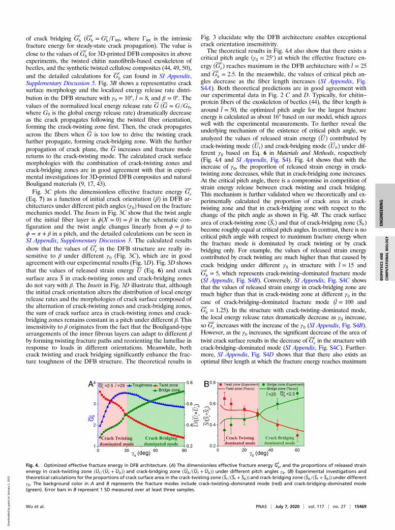
Fig. 3 elucidate why the DFB architecture enables exceptionalcrack orientation insensitivity.The theoretical results in Fig. 4A also show that there exists a
critical pitch angle (γ0 ≈ 25∘) at which the effective fracture en-ergy (Gc
e) reaches maximum in the DFB architecture with l = 25and G
cb = 2.5. In the meanwhile, the values of critical pitch an-
gles decrease as the fiber length increases (SI Appendix, Fig.S4A). Both theoretical predictions are in good agreement withour experimental data in Fig. 2 C and D. Typically, for chitin–protein fibers of the exoskeleton of beetles (44), the fiber length isaround l = 50, the optimized pitch angle for the largest fractureenergy is calculated as about 16° based on our model, which agreeswell with the experimental measurements. To further reveal theunderlying mechanism of the existence of critical pitch angle, weanalyzed the values of released strain energy (U) contributed bycrack-twisting mode (Ut) and crack-bridging mode (Ub) under dif-ferent γ0 based on Eq. 6 in Materials and Methods, respectively(Fig. 4A and SI Appendix, Fig. S4). Fig. 4A shows that with theincrease of γ0, the proportion of released strain energy in crack-twisting zone decreases, while that in crack-bridging zone increases.At the critical pitch angle, there is a compromise in competition ofstrain energy release between crack twisting and crack bridging.This mechanism is further validated when we theoretically and ex-perimentally calculated the proportion of crack area in crack-twisting zone and that in crack-bridging zone with respect to thechange of the pitch angle as shown in Fig. 4B. The crack surfacearea of crack-twisting zone (St) and that of crack-bridging zone (Sb)become roughly equal at critical pitch angles. In contrast, there is nocritical pitch angle with respect to maximum fracture energy whenthe fracture mode is dominated by crack twisting or by crackbridging only. For example, the values of released strain energycontributed by crack twisting are much higher than that caused bycrack bridging under different γ0 in structure with l = 15 andG
cb = 5, which represents crack-twisting–dominated fracture mode
(SI Appendix, Fig. S4B). Conversely, SI Appendix, Fig. S4C showsthat the values of released strain energy in crack-bridging zone aremuch higher than that in crack-twisting zone at different γ0 in thecase of crack-bridging–dominated fracture mode (l = 100 andG
cb = 1.25). In the structure with crack-twisting–dominated mode,
the local energy release rates dramatically decrease as γ0 increase,so G
ce increases with the increase of the γ0 (SI Appendix, Fig. S4B).
However, as the γ0 increases, the significant decrease of the area oftwist crack surface results in the decrease ofG
ce in the structure with
crack-bridging–dominated mode (SI Appendix, Fig. S4C). Further-more, SI Appendix, Fig. S4D shows that that there also exists anoptimal fiber length at which the fracture energy reaches maximum
Fig. 4. Optimized effective fracture energy in DFB architecture. (A) The dimensionless effective fracture energy Gce, and the proportions of released strain
energy in crack-twisting zone (Ut=(Ut + Ub)) and crack-bridging zone (Ub=(Ut + Ub)) under different pitch angles γ0. (B) Experimental investigations andtheoretical calculations for the proportions of crack surface area in the crack-twisting zone (St=(St + Sb)) and crack-bridging zone (Sb=(St + Sb))under differentγ0. The background color in A and B represents the fracture modes include crack-twisting–dominated mode (red) and crack-bridging–dominated mode(green). Error bars in B represent 1 SD measured over at least three samples.
Wu et al. PNAS | July 7, 2020 | vol. 117 | no. 27 | 15469
ENGINEE
RING
BIOPH
YSICSAND
COMPU
TATIONALBIOLO
GY
Dow
nloa
ded
by g
uest
on
Janu
ary
1, 2
022
in DFB structure, and the calculated results are consistent with theexperimental results in Fig. 2D.To answer why twist angle distribution in a pitch of natural
Bouligand architectures [e.g., stomatopod dactyl club (9) andbeetle exocuticle (44)] is linear, we designed nonlinear twistangles distribution in a pitch of the 3D-printed DFB compositesto reveal the effects of the twist angle distribution on thefracture-resistance (SI Appendix, Figs. S5 and S6), and the de-tailed calculations and discussions can be seen in Materials andMethods and SI Appendix, Supplementary Discussion 4. Our cal-culated results (SI Appendix, Fig. S5) show that the effectivefracture energy in the DFB structure with nonlinear twist angledistribution is lower than that in the system with linear twistangle distribution. In addition, the optimized fracture energy forthe DFB composites with nonlinear twist angles distribution canalso be achieved through tuning the pitch angles and fiber length(SI Appendix, Fig. S5 E and F). These trends predicted by frac-ture mechanics model are consistent with that in experimentalmeasurements of 3D-printed DFB composites with nonlineartwist angles distribution (SI Appendix, Fig. S6). The aboveanalyses demonstrate that linear twist angle distribution in apitch in comparison to the selected nonlinear twist angle distri-bution may facilitate higher resistance to fracture.
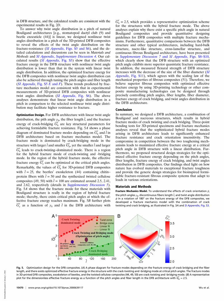
Optimization Design. For DFB architecture with linear twist angledistribution, the pith angle γ0, the fiber length l, and the fractureenergy of crack-bridging G
cb are key structural parameters for
achieving formidable fracture resistance. Fig. 5A shows a phasediagram of dominated fracture modes depending on G
cb and l in
DFB architecture based on fracture mechanics model. Thefracture mode is dominated by crack-bridging mode in thestructure with larger l and smaller G
cb, yet the smaller l and larger
Gcb leads to crack-twisting–dominated mode. There is a region
for the hybrid fracture mode of crack-twisting and -bridgingmode. In the region of the hybrid fracture mode, the effectivefracture energy G
ce can be optimized at the critical pitch angles.
Remarkably, the values of Gcb for 3D-printed DFB composites
with l = 25, the beetles’ exoskeleton (44) containing chitin–protein fibers with l = 50 and the synthesized twisted cellulosecomposites (49, 50) with l = 100 are estimated around 2.5, 2.41,and 2.62, respectively (details in Supplementary Discussion 5).Fig. 5A shows that the fracture mode for these materials withBouligand structure is really in the region of hybrid fracturemode; thereby, there exists critical pitch angles at which the ef-fective fracture energy reaches maximum. Fig. 5B further plotsG
ce as a function of γ0 and l in the DFB architecture with
Gcb = 2.5, which provides a representative optimization scheme
for the structures with the hybrid fracture mode. The aboveanalyses explain why there exist a specific pitch angle in naturalBouligand composites and provide quantitative designingguidelines for DFB composites with multiple fracture mecha-nisms. Furthermore, quantitative comparisons between the DFBstructure and other typical architectures, including hard-bulkstructure, nacre-like structure, cross-lamellar structure, andcontinuous fibrous Bouligand architecture, have been presentedin Supplementary Discussion 7 and SI Appendix, Figs. S8–S10,which clearly show that the DFB structure with an optimizedpitch angle exhibits more superior quasistatic fracture resistance.In addition, the measured flexural strength of DFB structureincreases with the decrease of the size of the fiber diameter (SIAppendix, Fig. S11), which agrees with the scaling law of themechanical properties of fibrous composites (51). Therefore, webelieve superior fibrous composites with optimized effectivefracture energy by using 3D-printing technology or other com-posite manufacturing technologies can be designed throughprecisely controlling pitch angles, fiber lengths, fiber diameter,fracture energy of crack bridging, and twist angles distribution inthe DFB architecture.
ConclusionIn summary, we designed a DFB architecture, a combination ofBouligand and nacreous structures, which results in hybridfracture modes of crack twisting and crack bridging. Three-pointbending tests for 3D-printed specimens and fracture mechanicsanalyses reveal that the sophisticated hybrid fracture modesarising in DFB architecture leads to significantly enhancedfracture resistance and crack orientation insensitivity. Thecompromise in competition between the two toughening mech-anisms leads to maximized effective fracture energy at a criticalpitch angle in DFB structure with a linear distribution. Fur-thermore, we proposed structural design strategies for the opti-mized effective fracture energy depending on the pitch angles,fiber lengths, fracture energy of crack bridging, and twist anglesdistribution in DFB composites. Our findings shed light on hownature has evolved materials to exceptional fracture toughnessand provide the generic design strategies for bioinspired formi-dable fracture-resistant fibrous composite systems that adapt toloads in various orientations.
Materials and MethodsFracture Mechanics Model. To understand the effects of crack orientation β,
the pitch angles γ0, discontinuous fibers length l, and twist angle distributionϕ in a rotation of 180° on the fracture energy of the DFB composites, wedeveloped a fracture mechanics model with the combination of cracktwisting and crack bridging, as illustrated in Fig. 3A and SI Appendix, Fig. S3.
Fig. 5. Optimization design for the DFB composites. (A) A phase diagram for fracture modes depending on the fracture energy of crack bridging and the fiberlength, and there exists optimized effective fracture energy in the structure with the crack-twisting and -bridgingmode at critical pitch angles. The fracture modesin 3D-printed DFB composites, exoskeleton of beetles, and the twisted cellulose composites (44, 49, 50) are crack-twisting and -bridging mode. (B) A representativeplot for the dimensionless effective fracture energy as a function of the pitch angles and fiber length in the DFB architecture with G
cb = 2.5.
15470 | www.pnas.org/cgi/doi/10.1073/pnas.2000639117 Wu et al.
Dow
nloa
ded
by g
uest
on
Janu
ary
1, 2
022
The details of theoretical derivations can be seen in SI Appendix, Supple-mentary Discussions 2–4 and Fig. S3.
The configurations of Bouligand layups are described by a power function:
ϕ = γn0πn−1
Xn + β, 0.5 ≤ n ≤ 2, [1]
where the crack orientation β is the angle between the axis of initial fiberlayer at notch tip and direction of the notch front (y axis). n = 1 representslinear distribution of twist angle along the crack propagation direction (xaxis), i.e., the pitch angle in a pitch is constant, 0.5≤n< 1 represents non-linear convex function distribution of twist angle and 1<n≤2 representsnonlinear concave function distribution of twist angle (SI Appendix, Fig.S5A).
The twisted crack shape can be described by the following:
Z = Ytan(ϕ(X)), 0 ≤ X ≤ π/γ0, − l/2 ≤ Y ≤ l/2, [2]
whereX = X=dis dimensionless coordinates along the crack propagation di-
rection, Y = Y=d, Z = Z=d; l = l=d is the dimensionless length of discontin-uous fibers, and d is the fiber diameter.
The local energy release rate Gt of crack twisting can be calculated asfollows (27, 52):
Gt = 1E[k′21 (1 − v2) + k′22 (1 − v2) + k′23 (1 + v)], [3]
where k′1, k′2, and k′3 are the local stress intensity factors described by thetwisted angle ϕ and tilted angle α, E is Young’s modulus, and v = 0.3 isPoisson’s ratio. And the normalized local energy release rate for crack
twisting is defined as Gt = Gt=G0, where G0 = (1 − v2)(K0I )2=E is the global
energy release rate and K0I is the global applied intensity factor of mode
I fracture.Based on the crack-bridging model (34), the normalized local energy re-
lease rate Gb = Gb=G0 and the normalized fracture energy Gcb = Gc
b=Γint forcrack bridging are given by the following:
Gb = 1/(1 + η)2, Gcb = (1 + η)2, [4]
where η is the toughening ratio induced by crack bridging, and Γint is theintrinsic fracture energy for steady-state crack propagation, which is a ma-terial constant reflecting the energy dissipation by the breakage of matrixmaterials.
Based on the maximum energy release rate fracture criterion, the nor-
malized energy release rate G = G=G0 for the DFB structure can be calculatedas follows:
G = max(Gt ,Gb). [5]
The released strain energy U in crack-twisting zone (Ut) and crack-
bridging zone (Ub) can be calculated by the integration of the local en-ergy release rate and crack area:
Ut = ∫ StGtdSt , Ub = ∫ Sb
GbdSb, [6]
where St = St=d2 is the dimensionless area of crack-twisting zone, and Sb isthe area of crack-bridging zone.
The dimensionless effective fracture energyGce = Gc
e=Γint with respect tothe area of undeflected crack plane can be calculated by the following (52):
Gce = π
γ0
l
∫ 0.5l−0.5l∫
π=γ00 Gcos θdxdy
, [7]
where θ is the angle between the normal to the twisted crack surface andnormal to the undeflected crack plane.
Microstructure Design and 3D Printing-Based Fabrication. The three-pointbending specimens with different architectures were 3D printed fromdesigned CAD models by using an Objet260 Connex 3D printer (StratasysLtd.). The printer is capable to print multiple materials simultaneously andhas a print precision of 16 μm in the layer deposition direction and 600 dpi inthe print plane. As shown in Fig. 1C, the dimensions of the 3D-printed single-edge notched bend samples consisted of 25 layers are H = 22.5 mm, L = 5H,W = H, t = 0.9 mm, h = H/5, d = 0.8 mm, and S = 80 mm, where H, L, W, t, h,d, and S denote height, length, width, interlayer space, notch length, thefiber diameter, and span length, respectively. The span length to heightratio is about 4, which ensures small end effect in the middle, and theprinted crack front is further sharpened with a fresh razor blade. For thestructures with different initial crack orientationsβ, the orientation of theinitial fiber layer is ϕ = β (Fig. 1D). The unidirectional architectures arecomposed of discontinuous fibers with a consistent orientation the same asthe orientation of the initial fiber layer at the notch front. In the orthogonaldiscontinuous fibrous composites, the orientation of initial fibers layer at thenotch tip is ϕ = β, and the subsequent orthogonally aligned fibers layers arestacked to form the structure. The DFB composites with different pitch an-gles are arranged with twisted plywood stacking of discontinuous fiberslayers. The theoretical volume fraction of the fibers with these parameterscorresponds to around 70%. The discontinuous fibers are made of a rigidpolymer (VeroWhitePlus; Young’s modulus is 0.8 ± 0.2 GPa), and the matrixis made of a soft rubber-like polymer (TangoblackPlus; Young’s modulus is0.2 ± 0.05 MPa). The details of base materials parameters are reported in SIAppendix, Supplementary Discussion 1 and Fig. S1.
Mechanical Testing. The three-point bending tests were carried out on aMaterial Test System (MTS criterion 43, MTS System Company) with constantdisplacement mode using 5-kN load cells. All tests were performed with asupport span of 80 mm at a loading rate of 0.5 mm/min. The failure mor-phologies of samples were recorded by a camera. The area of crack twistzones and crack bridge zones was measured by ruler based on the post-failure surface of experiment samples. The detailed characterizations of thepostfailure patterns in 3D-printed samples can be seen in SI Appendix,Supplementary Discussion 6 and Fig. S7.
Data Availability. All data are included in the manuscript and SI Appendix.
ACKNOWLEDGMENTS. This work was supported by the National NaturalScience Foundation of China (Grant 11672285), the Strategic Priority Re-search Program of the Chinese Academy of Sciences (Grant XDB22040502),the Collaborative Innovation Center of Suzhou Nano Science and Technol-ogy, and the Fundamental Research Funds for the Central Universities(WK2090040043). This work was partially carried out at the University ofScience and Technology of China Center for Micro- and Nanoscale Researchand Fabrication.
1. M. A. Meyers, J. McKittrick, P.-Y. Chen, Structural biological materials: Criticalmechanics-materials connections. Science 339, 773–779 (2013).
2. U. G. Wegst, H. Bai, E. Saiz, A. P. Tomsia, R. O. Ritchie, Bioinspired structural materials.Nat. Mater. 14, 23–36 (2015).
3. Z. Liu, M. A. Meyers, Z. Zhang, R. O. Ritchie, Functional gradients and heterogeneitiesin biological materials: Design principles, functions, and bioinspired applications.Prog. Mater. Sci. 88, 467–498 (2017).
4. W. Huang et al., Multiscale toughening mechanisms in biological materials and bio-inspired designs. Adv. Mater. 31, e1901561 (2019).
5. R. O. Ritchie, The conflicts between strength and toughness. Nat. Mater. 10, 817–822(2011).
6. S. Ling, D. L. Kaplan, M. J. Buehler, Nanofibrils in nature and materials engineering.Nat. Rev. Mater. 3, 18016 (2018).
7. S. E. Naleway, M. M. Porter, J. McKittrick, M. A. Meyers, Structural design elements inbiological materials: Application to bioinspiration. Adv. Mater. 27, 5455–5476 (2015).
8. Y. Bouligand, Twisted fibrous arrangements in biological materials and cholestericmesophases. Tissue Cell 4, 189–217 (1972).
9. J. C. Weaver et al., The stomatopod dactyl club: A formidable damage-tolerant bi-ological hammer. Science 336, 1275–1280 (2012).
10. R. O. Ritchie, Natural materials: Armoured oyster shells. Nat. Mater. 13, 435–437
(2014).11. L. K. Grunenfelder et al., Ecologically driven ultrastructural and hydrodynamic designs
in stomatopod cuticles. Adv. Mater. 30, 1705295 (2018).12. I. Kellersztein, S. R. Cohen, B. Bar-On, H. D. Wagner, The exoskeleton of scorpions’
pincers: Structure and micro-mechanical properties. Acta Biomater. 94, 565–573
(2019).13. H. O. Fabritius, C. Sachs, P. R. Triguero, D. Raabe, Influence of structural principles on
the mechanics of a biological fiber-based composite material with hierarchical or-
ganization: The exoskeleton of the lobster Homarus americanus. Adv. Mater. 21,
391–400 (2009).14. J. Wu et al., Natural hydrogel in American lobster: A soft armor with high toughness
and strength. Acta Biomater. 88, 102–110 (2019).15. H. Quan, W. Yang, E. Schaible, R. O. Ritchie, M. A. Meyers, Novel defense mechanisms
in the armor of the scales of the “living fossil” coelacanth fish. Adv. Funct. Mater. 28,
1804237 (2018).16. N. A. Yaraghi et al., A sinusoidally architected helicoidal biocomposite. Adv. Mater.
28, 6835–6844 (2016).
Wu et al. PNAS | July 7, 2020 | vol. 117 | no. 27 | 15471
ENGINEE
RING
BIOPH
YSICSAND
COMPU
TATIONALBIOLO
GY
Dow
nloa
ded
by g
uest
on
Janu
ary
1, 2
022

17. N. A. Yaraghi et al., The stomatopod telson: Convergent evolution in the develop-ment of a biological shield. Adv. Funct. Mater. 29, 1902238 (2019).
18. E. A. Zimmermann, R. O. Ritchie, Bone as a structural material. Adv. Healthc. Mater. 4,1287–1304 (2015).
19. X. Li et al., Spear and shield: Survival war between Mantis shrimps and abalones. Adv.Mater. Interfaces 2, 1500250 (2015).
20. L.-B. Mao et al., Synthetic nacre by predesigned matrix-directed mineralization. Sci-ence 354, 107–110 (2016).
21. H.-L. Gao et al., Mass production of bulk artificial nacre with excellent mechanicalproperties. Nat. Commun. 8, 287 (2017).
22. Z. Yin, F. Hannard, F. Barthelat, Impact-resistant nacre-like transparent materials.Science 364, 1260–1263 (2019).
23. H. Gao, B. Ji, I. L. Jäger, E. Arzt, P. Fratzl, Materials become insensitive to flaws atnanoscale: Lessons from nature. Proc. Natl. Acad. Sci. U.S.A. 100, 5597–5600 (2003).
24. Y. Ni, Z. Song, H. Jiang, S. Yu, L. He, Optimization design of strong and tough na-creous nanocomposites through tuning characteristic lengths. J. Mech. Phys. Solids 81,41–57 (2015).
25. S. Nikolov et al., Revealing the design principles of high-performance biologicalcomposites using ab initio and multiscale simulations: The example of lobster cuticle.Adv. Mater. 22, 519–526 (2010).
26. R. Arridge, Fracture of fibre reinforced materials. Nature 223, 941 (1969).27. N. Suksangpanya, N. A. Yaraghi, D. Kisailus, P. Zavattieri, Twisting cracks in Bouligand
structures. J. Mech. Behav. Biomed. Mater. 76, 38–57 (2017).28. E. A. Zimmermann et al., Mechanical adaptability of the Bouligand-type structure in
natural dermal armour. Nat. Commun. 4, 2634 (2013).29. Z. Jia, Y. Yu, S. Hou, L. Wang, Biomimetic architected materials with improved dy-
namic performance. J. Mech. Phys. Solids 125, 178–197 (2019).30. F. D. Fischer, O. Kolednik, J. Predan, H. Razi, P. Fratzl, Crack driving force in twisted
plywood structures. Acta Biomater. 55, 349–359 (2017).31. A. Zaheri et al., Revealing the mechanics of helicoidal composites through additive
manufacturing and beetle developmental stage analysis. Adv. Funct. Mater. 28,1803073 (2018).
32. Y. Gao, Z. Guo, Z. Song, H. Yao, Spiral interface: A reinforcing mechanism for lami-nated composite materials learned from nature. J. Mech. Phys. Solids 109, 252–263(2017).
33. S. Yin et al., Hyperelastic phase-field fracture mechanics modeling of the tougheninginduced by Bouligand structures in natural materials. J. Mech. Phys. Solids 131,204–220 (2019).
34. Y. Shao, H.-P. Zhao, X.-Q. Feng, H. Gao, Discontinuous crack-bridging model forfracture toughness analysis of nacre. J. Mech. Phys. Solids 60, 1400–1419 (2012).
35. J. W. Pro, F. Barthelat, The fracture mechanics of biological and bioinspired materials.MRS Bull. 44, 46–52 (2019).
36. L. K. Grunenfelder et al., Bio-inspired impact-resistant composites. Acta Biomater. 10,3997–4008 (2014).
37. S.-M. Chen et al., Biomimetic twisted plywood structural materials. Natl. Sci. Rev. 5,703–714 (2018).
38. L. Mencattelli, S. T. Pinho, Realising bio-inspired impact damage-tolerant thin-plyCFRP Bouligand structures via promoting diffused sub-critical helicoidal damage.Compos. Sci. Technol. 182, 107684 (2019).
39. R. Chen et al., Transparent impact-resistant composite films with bioinspired hierar-chical structure. ACS Appl. Mater. Interfaces 11, 23616–23622 (2019).
40. N. Suksangpanya, N. A. Yaraghi, R. B. Pipes, D. Kisailus, P. Zavattieri, Crack twistingand toughening strategies in Bouligand architectures. Int. J. Solids Struct. 150, 83–106(2018).
41. Z. Song, Y. Ni, S. Cai, Fracture modes and hybrid toughening mechanisms in oscillated/twisted plywood structure. Acta Biomater. 91, 284–293 (2019).
42. S. Amini, M. Tadayon, S. Idapalapati, A. Miserez, The role of quasi-plasticity in theextreme contact damage tolerance of the stomatopod dactyl club. Nat. Mater. 14,943–950 (2015).
43. W. Yang, H. Quan, M. A. Meyers, R. O. Ritchie, Arapaima fish scale: One of thetoughest flexible biological materials. Matter 1, 1557–1566 (2019).
44. R. Yang, A. Zaheri, W. Gao, C. Hayashi, H. D. Espinosa, AFM identification of beetleexocuticle: Bouligand structure and nanofiber anisotropic elastic properties. Adv.Funct. Mater. 27, 1603993 (2017).
45. Y. Yang et al., Biomimetic anisotropic reinforcement architectures by electrically as-sisted nanocomposite 3D printing. Adv. Mater. 29, 1605750 (2017).
46. Y. Yang et al., Recent progress in biomimetic additive manufacturing technology:From materials to functional structures. Adv. Mater. 30, e1706539 (2018).
47. S. Gantenbein et al., Three-dimensional printing of hierarchical liquid-crystal-polymerstructures. Nature 561, 226–230 (2018).
48. G. X. Gu, M. Takaffoli, M. J. Buehler, Hierarchically enhanced impact resistance ofbioinspired composites. Adv. Mater. 29, 1700060 (2017).
49. B. Natarajan et al., Binary cellulose nanocrystal blends for bioinspired damage tol-erant photonic films. Adv. Funct. Mater. 28, 1800032 (2018).
50. J. Song et al., Processing bulk natural wood into a high-performance structural ma-terial. Nature 554, 224–228 (2018).
51. H. Zhu et al., Anomalous scaling law of strength and toughness of cellulose nano-paper. Proc. Natl. Acad. Sci. U.S.A. 112, 8971–8976 (2015).
52. K. T. Faber, A. G. Evans, Crack deflection processes—I. Theory. Acta Metall. 31,565–576 (1983).
15472 | www.pnas.org/cgi/doi/10.1073/pnas.2000639117 Wu et al.
Dow
nloa
ded
by g
uest
on
Janu
ary
1, 2
022