disclaimer notice - defense technical information center · disclaimer notice this document is best...
TRANSCRIPT

DISCLAIMER NOTICE
THIS DOCUMENT IS BEST QUALITY
PRACTICABLE. THE COPY FURNISHEDTO DTIC CONTAINED A SIGNIFICANT
NUMBER OF PAGES WHICH DO NOTREPRODUCE LEGIBLY.

A MODEL FOR FLUORINE RECOM9BINATION
AT A METAL SURFAE
by
Eric 3. Jumper, .S., M.S.
CAPT USAF
Approvetd:
4 iL
00,
Accepted:
NATONAt UCKNKALINI• *# I• A T C•I•ct

A NML FOR FUM*NI RECPNoIXATION
AT A METAL SUIFACE
D| SSISTAT i ON
Presented to the Faculty of the School of Engiseering
of the Air Force Is.stitute of Technology
Air University
in Partial Fulfillfent of the
Requirewents for the ;icz of
Doctor of Philosophy
by
Eric J. Jwrer. I.S.. u.S.
Approved for public release; distribution unlialted.

IAA wrp$1OWEm
* 'ITLO t.%P-4'~ *6AP9 Sw~ vk Ofg W *OV0 StMOCI COV14tv
A ULM wMi uORM nCMSUWtIW FbS. "Se""49tSMVT A MAL SMACS -H~
Air t" 91mls"titte of T*thsWI*&-4 (AflTIO)Iomt-Petterov An1, Ohio 434)33
Air Pwrc* Wapoo Ldmwtor7v (AMWt) r191)F W~~~irteand Anl, New Hanle* S1I1ofP
App.%uvv for putolic remlease; dA.,trlhuttoo w~li~mtod.
_11 -*I*tv'rt tI "twEqw It t A low t 10 1tON if opts"v Ow Ne9Wu9
Ijppioved tot-r put c, xrq.'ase; IAII Ant M9-1I
Ircrtor of 'Informetito
Kat t vvar9'ns ft omb i not Iont Catalytic Fluorine Recoutinaticn
Chemical Laser viscots Resoale FlowvCheolcAl Loper floasle Ft-ow
A steady state medel for fluorine &too rtombinstion for tooerateresloes than aQ K 0tt a vwtal cato.17tii *Urtace wag doveloped "ased on theRideal hetetugoneveta goattiotn oprt-hnis. The "*Ie to comprised of threedistinct procevtecs: (1) the bond itka process of t*as-Vhas# fluorine *toesto the inetld surface. (2) the colis ione and subi'tqtucot roccofbleistioo
process of gao-phase stv*ýq and surlact-bonded fltaritle *toss and (1) the
00 ' 1473 ri~o

I&$ the Surface eOrvvca.. Th( "d01 was evqq~awtl with actual f Nor toorto~w41ltantlan data takeni livt a isfkel, tube to wbtc% * gas saitu're ofStOMIC [lijotitie "circular !!Uoftne, and arsoiv flem~v,4 ?be TOOV~Its of
Wei comprtsos validated the WW40 akd exte~ede the vatifiCa44as of theWea.l sachasism for beterOgeompos f~ctmtinattes.
Claw~tatief usisw, the Vail rwC06tsat Lo" 90"1 vote able fair 4two-410MmIOs,. all# 00*0i. Of the typo uis"~ In fltwynn mhe"Ical lagersmatoo a two-dt"yin~ifal 'hestrdi 3y mactifts laIsmar boundary laygv c4M-Peter code. Thew £es'ts f thoesq evatol~uiks sbaw that the Vail [email protected] .e"taatiallp ofilected th. LuI"eratalv profiSlaes 64Well as vallbeat t ransfer is chemIcal lam.t .tae The abut of etamit f luorinedepleted through wall recamblw~.tteo w.%, aVowi to hie on the order of atkf~r4 of the ais-tlel fluarime coeeratitattom for t*** aorala cimf iguraties
t 4 v &>f r1

Pre face
The origin of this dlssertation dates back to a trip
t mae t2 the Yeappas Laboratory In Merch 1973. At that
time the problem of fluorine recombination seemed to 0e to
be an extremely pressing oa%, &ad one which I thought
would certainly be solved by the tim I woa ready to begin
my restarch. I returned to AMI! and began to prepare my-
self for embarking on a parametric srfady of he&: transfer
effects die to fluorine recasbinatbon on the wells of the
"small nottles in a fluorine chemical laser using someone
ole's receabimation model (which I assumed would be in
existence whim I needed it).
While t uss back at AFMT, ar iLteresting thing took
place In fluorlie chemical laser circles. It yes the dis-
covery of the infamous 'Ifot Chain" fluorine laser reaction.
In effect the Hot Chain was advertised as being able to
produce excited HF and DF using a reaction which required
only small amounts of *tonic fluorine and large amounts of
molecular fluorine. The effect of this "discovery" was to
put an end to the urgen':y of developing a fluorine wall
recoublnation model. Thus, by the time I arrived at the
Weapons Laboratory to begin my parsmtric itudy, nothing
had been done on developing a recombination model. The
model was still considered an interesting problem but no
longer an urgent one. So. I began the work of developing
iil

the recombination model presented here. In the same time
fram some of r1•o early tests using the Hot Chain were
beiam usdertakem with aegative results but high hopes.
About six seths ago people beaos tv• realize that the
Nat Chain was mot all it had beesta 6sg*4d t'. be. Suddanly,
voll recombination was egals as iUmrtýat sad presaing
problem and I had people asklag for my odel. to this
rotard, I found the work moast excitiaul epAeially $loco,
because of the time involved is performing the research,
most dissertatios topics are sot oa such immedaste
importance. So, so I begin thauking those lafividuals
who aided mo it ay work, I would first like to thank who-
ovet It was who firtt suggeste4 that the amawer tO fluorine
wall recombination vwa the Not Chain.
It all seriousness, I would like to thank all those
at the Weapons Laboratory who were of such help to Am, in
particular, LtCol Jay Roland, LtCol David Ericson, Maj
Dick Harris, a special thanks to LtCol Dick Rober4s for
his patient car, and, certainly not least, Mrs Esther
Caster for typing this dissertatici. I am also indebted
to several members of the AFIT faculty, in particular, my
advisor Dr James Hitchcock for ti, helpful suggestions, and
comeents and Dr Andrew Shine for his confidence in ms.
I would like to express a very special thanks to Dr
Casper Ultee of V'aited Aircraft Research Laboratory fur
iv
Ij
graciously making Mis previously unpublished data avail-
able to me for this study,
Pimally, to my wife Marge and my chiAdren John rad
Christy I want you to know how •ihsakful am for your con-
stont love, understanding and sacrifice over tht long
three veara since I began work on my PhD. To you three I
"dedicate this dissertation.
ITic J. Jumer
V

;pt~ents
Pr Of . .e . . . . . . . . . . . . . . . . . . . Iii
List of Figures . . . . . . * A A*A Vit
Litt of Tables . .. .. . . .... . .4 *
LiLt of Symbols . . . . . . . . . . . . .. .. . .. . xi .
Abstract . . A . . A . . A . . A . . . . A A . . . . . XIV
|. Introduction .. .. . . .. A . . .
background .. . .. . . . . . . . . . . . . IHeterogeneous Recombination . . . . . . . .Review of Available Data for Halooeft WailReco~bination .. .. . A A . .4 W # 4Objectives and Scope of the Present Study • 11
1!. Fluorine Wall Recombination model . . . . . .. 13
Goa Phase Kinetics . . ... . . . . . . . . 13Wall Interaction Phenomena . . . . ..... 1Late Process and Equations . .... .... 24
I11. Low Pressure Pipe Flow with Wall Recombination . 29
Ultee Experiment . . . . . . . . 29Aaalytic .4odel . . . . . . . . . . . . 31^ppiica~tostty twifierie . . . . . . . . . . . 33
IV. Comparison of Theoretical Model vithExperimental Data . . . ... . 3S
Ot|c¢ing Coefficients . . 3SComparison of Pipe flow Catclulatiuns wvtData . . . .. . . ............... 3S
V. Effects of Recombination in Chemical LaserNa2I1sa . . . . . . ............... 40
Flow Equations . A * A . . . . . A . .4 4$Thermodynanic Properties . ... ..... A S1Hom•geneous Reactions ............. ...... SiTransport Properties ....... ......... . S2boundary Conditions . . .... . . . . . ... SSResults Of Ncz.le 1# lo Computations . . . S?
'I

Vrutext$
VI. Comelusions and Recembiaatios. . . . . . . . 74
bibliography . . .. . . . . . . . . . . . . . . . .
Appadtz A: Solution of the Equations for the Gas-Well Collision Model . .. . . .. . .._ . .
Appendix 2: Difference Iquations . . . . . . . . ..
Appendix C: Derivation of boundary Coaditious forF and ki Cuccatraticas . . . . . . . . . 93
Appendix D: Teeperature and Pressure Depeadeace ofthe Fluorine Wlal RecombinationCoefficleht . . . . . . . . . . . . . .
Vita . . . . . . .. . . . . . . . . . . . . . . . . . 1
vii

I Chmicaal Laser Operatic4,,. . .. 3
I Cut-Away vievw of Nozzle fask and mtixin. .t. .. . . . .. . . . . . . . . . . .
$ Calculated flrmalizod Intensity Distributionvs a r~imemtal. Normalized Intensitymlstrbuti .., . . . . . ,.. .. . , . ..
4 Probability Density Distribution of thePan -iDaeus ionsl Velocity Component atStb* vs I1 . . . . . . . . . . . . .. . lS
5 Physicsl Adsorption Potential Well . . . . . 1.
G Gas-Vall Collision Model . .. . . . . . 1
I U11e Experimental Apparatus . . . . . . . . 0
I Ov-Dimensionas Pipe flow ConcentrationDepletion . . . . . . . . . . . . . . . . . 32
0 Sticking Coefficient for Atomic Fluorine . . 36
10 Sticking Coefficient for Argon ......... . . 37
II Sticking Coefficient for Helium . . . . . . .
1? Comparison of 4*del with Experinental Data,Plotted is the % F Remaining at the End ofthe Nickel Test Sanple vs. Steady StateTemperature of tO SaMple .......... . 40
13 Yffect of Varying the Steric Factor .... 42
14 Effective Recombinstion CoefficlentCalculated From Ultee Experinental DatoUsing Equation (34) .............. . . . . . 44
IS Maximum Fluorine Wall RecombinationCoefficient vs. Temperature for a TotalPressure of 2.7 Torr, 00t Argon DiluentFlow, and 101 Fluorine Dissociation. ..... 46
16 Flow Geometry .......... . so
viii
I P
17 JouNdery Condition Noanclature ....... 5
18 Noeale Contour and Pressure Profile ..... 56
1t Velocity Profile at Throat . . . . .. .. 59
24 Velocity Protile at Exit Plane . . . , .... . 0
21 Teeperature Profile at the Throat . . . .. 6,2
22 Teoperature Profile at ,he exit Plane. . . . 63
K$ Nent Transfer to the Nettle Vall . . . . . S
24 Concentration Profiles at Throat .. . , * 67
21 Coacentratin Profiles at Exit Plane . . . .
Is Dpletion of F Concentration for Two StreamTubnes . . . . . . * 09 * 41
27 Depletior of F Integrated 0'yer Entire Flow . 70
2O Recombtnation Coefficient . . .. . .. . . . 71
A.l Gas-Vall Collision System. . . . . . . . . 1
A.2 Initial Angie at Onset of Collision vs. Atom-Out Energy . . . . . . . . . . . . .. . .. . . 7
A.3 Probability of Atom gein& Irappe. ........ . 7
3.1 Cell Nomenclature . ............... 38
C.1 Conservation Equations for Stagnant Cell . 93
DA Fluorine Wall Recombinatiou Coefficient vs.Teom-vature for 90t Diluent Flows of Argon andHelium with 901 Dissociation . . . . . . . 99
D,2 Fluorine Reccubination Coefficient vs. PartialPressure of Atomic Fluorine for 90t ArgonDiluent and 90 Fluorine Dissociatiun . . . 100
.D3 Fluorine kecombination Coefficients vs.Patial Pretstore of Atomic Fluorine forHelium Diluent ..... ............. . . . . . 101
is

List of Tables
Table I
I Physical Parameters of Ultee Expor~lent .3.. 39
:! Ccmputstional Parameters . .. .. .. .. . .. 41
III Input Conditions ..... .............. 64
IV Flux Denominator ....... .......... . . . . . 73
x

L9st of jX5bol,
Ca Surface sites per unit area
C Specific heat at constant pressurep
P Diffusivity
D Well depth
ED Desorption energy
1 Mole-sess ratio of species i (*olIs-gO
h Planck constant
% Planck constant divided by 2v
h I Enthalpy of species i
.E Thermal conductivity
& i Theroal conductivity of sprite i
Kb Backward te constant
Kf Forward rate constant
k Boltzmann constant
k| Gas-rql spring constant
ks Surface spring constant
a Mass of atop
i Rate of impingement
n V•imL tic OT surface number density
IP Pressure
q Orbital raoius of electrons of atom times charge
I Universal go!, constant
K I fquilibrium position
T Position or pip~e radius depending on context
Ii

List of .ols
S Sticking coefficient
so Clean surface sticking coefficient
St Steric factor
T Temperature
t€ Time of collision
tDIFF Characteristic time of diffusion
tREC Characteristic time of recombination depletion
U Flow velocity
u X-component of velocity
V Velocity
V(r) Repulsive potential
V 112,3 Velocity conponents on atomic scale
v Y-componert of veloc~ity
W Mean atomic velocity
WOr) Attractive potential
Vi Rate of production of ipecl.es i
X Longt.ttudinal position
x Axial position
Y Pnoition of ga% atom
Y Velocity of gas atom
y Transverse position
Z Position of surface atom
Z Velocity of surface atum
Iii

List of Lmtb3is
Recombination coefficient
4 Thermal desorption
Well depth
€ Maximum energy of atraction between colliding atoms
* Surface coverage ratio
g Interaction distance
Nean free path
Viscosity
0 Cross section
z NoMl fraction
O Reduced collision integrel
Frequency
D Diluent or diffusion depending on context
F Fluorine
T Total
o Irat.1al
I Specie, I
a Gas
s Surface
U Viscosity
xili

r]
DS/141/ 7S -Z
Abstract
A steady state model for fliorine atoo recombination
for temperatures less then 60 K on a metal catalytic sur-
face was developed based on the Rideal heterogeneous reac-
tion mechanism, The model is comprised of three disttnct
processes: (1) the bonding process of gas-phase fluorine
atoms to the metal %urface. (M) the collision a&Z ."hse-
quent recombination process of gas-phase atoms and surface-
bonded fluorine atoms and (3) the rate process at which
the bonding and recombination take place considering the
surface coverage. The model uas compared with actual
fluorine recombination data taken for a nickel tube in
which a gas mixture of atomic fluorine, molecular fluo-
rine, and argon flowed. The results of this comparison
validatcd the model and extended th- verification of the
Ridesl mechanitm for heterogeneous recombination.
Important characteristics of fluorine wall recombina
tion were demonstrated through use of the model. The
recombination coefficient, defined as the ratio of the
recombination resulting wall collisions to the total wall
cotllilons, was found to be a strong function of tempera-
ture. The recombination coefficient dropped rapidly from
a maximum of approximately 10 "? at 400 K %o approximately
I x lO6 at 7OO V due to thermal desorption, The
xiv
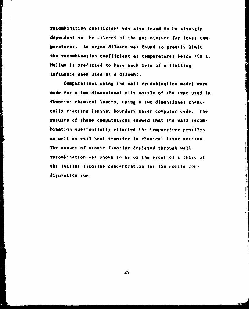
recombination coefficient was also found to be strongly
dependent on the diluent of the gas nixture for lower tem-
peratures. An argon diluent was found to greatly limit
the recombination coefficient at temperatures below 4CO 1.
Helium is predicted to hove much less of a limiting
influence when used as a diluent.
Computations using the wall recombination model wero
*ade for a two.dimensionel alit nozzle of the type used in
fluorine chemical lasers, usiug a two-dimensional chomn-
cally reacting laminar boundary layer computer code. The
results of these computations showed that the wall recon-
binatinn 5ubqtantially effected the tesper:tizre pr-.ftles
as veil as wall heat transfer in chemical laser noz:Ies,,
The amount of atomic fluorine deplIeted through walA
recombination %as shown to be on the order of a third of
the initial fluorine concentration for the nozzle con-
figuration run,
xy

A MODEL FOR FLUOR.NT LCONBNWATION
AT A METAL 3URFACE
1. Introduction
D&ý17und
For some yeascs now it has h.P k!'-W" that CheCirfl
lqgsrs, have a much higher perfotwance potential than gas
dynamic lasers, GDL. in terms of volumetric efficiency,
chemical efficiency, and gair (Ref '). ecauoe of the
simpler technology involved, GDL's were the first losers
to be explored at the development level for th" production
of a high power laser. Research, however, has continued
on chemical laser. to )ay the groun4 work for the second
generation of high po~er lasers. Since 1971 considerablt
effort has been expended in the productign of comprehensive
gusdyvisvic computer sodels for the ntudy and design of
chemical laCers (P-t Z).
Computer modeling of the nozzle banks, lasing ravi-
tie% and diffusor sections is just beginnint to gain
acceptance. Usahle results are beginning to be produced
toward the fival teal. of merging the separate sodels of
each of the components into an overal! desigr code. Of
major importance to these coOes are the phy'stchemical
inputs. These inputt are presently being looked at in
greoat detail in an attempt to further refine the semi-
empirical models.
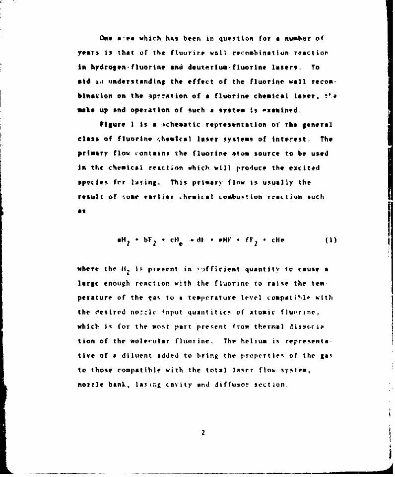
One aýcea which has been in question for a number of
years is that of the fluurire wall recombination reactior
in hydrojen-fluorine *n6 deuterium-fluorine losers. To
aid toi understanding the effect of the fluorine wall recom-
bination on the optr-tion of a fluorine cheaital loser. :.t
make up end opetation of such a system is oxemined.
Figure I is a ichematic representmtion of the general
class of fluorine 'hein1cal laser systems of interest. The
primary flow contains the fluorine atom source to be used
In the chemical reaction which will pro4uce the excited
species fer lAting. This primary flow is usualiy the
result of -,ose earlier chemical combustion reaction such
as
a"z * bF 2 * cH e -dF 0 NI' , r f * dce (1)
where the iI, iý ptrsent in 7afficient quantity io cause a
large enough reaction with the fluorinc to raise the ten.
perature of the gas to a temperature level compatible with
the oesired no,:.le Anput quantititrc- of atomic fluorine,
which i% for the 00-t Par! present from thernal dissocis
tion of the molescular fluorine. The helium is representa-
tive of P diluent added to bring the propepcrtle, of the gSa
to those compatible with the total laser flob system,
noizle bank, l&i; cavity and dlffusor section.

r____________________________ ______________
I
rt
p-4
'ISI.9a.0
1< j -
S
-J
-4
SU
-4
-4
___ 1W11
3

Referring to Figure 2, the primary flow is then
accelerated through the primary noxrles of the nozle bank
reaching velocities ranging from Math Z to Mach S depending
on the particular laser configuration. It is on the walls
of these nozzles that the fluorine reombinatior, can take
place. Upon exit from the nortles the primary nozzle flow
is joined in the mixing and lasing cavity by the adjacent
SecOwdary nozzle flown .onsistlng of' either Iz or . The
jets mix in the mixing zoneA indicated in Figure Z where
the excited Ifr(v) lasing ttate5 are formed in reactions of
the type
H1 Z F-- fF(vi ' H (2)
the VirrerN (TerM the Oltical kavity and piuer is extracted
ffro the I-avity thfruOth t,,e wrrT.' havtnjý rprtial trans-
amit tnce.
There ate oany factor% h'earing on the natching if
t'heoretical gain data wri ot-ervel ejxerimettal airn doata
(Ref' 31 Tv oentiot a fe% areaý %here inadeqkua w•odeling
Omy be rTe~pn~.iheC for the m|i.mat-hi,. the ri-l1oving are
g~ven:
a) Puopinp rr.-itlon rates for rest-tions of the type
F Hz bI• (v) * I (3)

CFLOWF ATOM4 jr'WY FLOWd
CCM~JnTtR d
c~xx~'a ~cuar ?O:.ZL
PA&SAGE RIMD"
Figure 2. (ot-Ahav View of Nx:le bmnk-ond ~4i.Klne Replcon
s

b) Stimulated emissiort reldxation rate% for
reactions of the tyre
RF(v) o hv - HF(v-I) * Zhv (4)
c) Vibrational-rotational and vibrations;-
translational deactivation rates for veactions
of the type
"1F(v) M .- F~v-tv) * 4 ($)
d) Single and multi-quantuw vibratiunal-vibrational
transfeT ratei' for riactions of thr type
"F( * 1IFv- Hl'%v'Ov) (15)
0 t1,W(v'-AV)
e) Turbu!ent mixing and diffto•ion proce-.e'e
() Free %tre~a f]kovrine rcomlbinatirn rste, €or
reactiton. of the type
Z1 * 4 '4 ~4 7)
g) Wall (trorine recohbinvio;. rates
It it unclear at this time exactl)- how each of thr factors

directly influence laser gain, is each plays an interrelat-
ed role with the other%. Of particular interest in this
study, however, is item g above. It is clear from Equa'v,i
(2) that the wall te.ombination reaction is a detrimentol
one. The less t available to the excitation reaction., the
less extited species, and tl'us, the less output iower
possible from the laser. Further understanding of the
possi'tle effect of this reac'tion has been pointed out by
Ferrell, Kendall. and Tong (Ref 4) and 4iketarian, kurriu5,
!4cDanal, and Thorenes (Ref S). Ferri e'.al, showo4 th:t
one might expect a large reduction in atomic fjoraine and
a pronoun ed gradient in the atomic and molecular c'ncen-
tration profiles at the exit plane of the primary nozzles
in a study in %-hich every flriorine atom colliding with the
wall va.Rt a2qumed to result. in a recombination, %qikatarian
et.al. showed the effect one milhi cxpect from %ia'h a con-
centration profile on the la!'er output. In on attcnpt to
explain anonalit- hetiern cat'culated and ohtrTed perform,
once curve•, thev inj;'t a crudely r~xinated kvntentnration
proftil into' ; (a"tv mling and l,.in coJe. The r'rult
was that a nolmifnri, initial fluorine (onkentration pro
file its tte laet tsvitv Cntrani'e *tua ed tuo important
effect.%, reduction in tie gain dthi to a dre'a~ce of
reactant, and oxial shlfting of the excitation i'eavtion!,
dowin %tream from the exit planh of the notileu' (tee Fligure
7

3). Thu,-% a an4rd urid~erstanding if thiv resctiov is rnf
lasers.
A!.tLeýiqus ReC:ophtfation. In general the laterik-
turL- contains N~n obundance of 'worW dealing vith the prob-
3,. *f ,tecont~naL ion at a cetalytic --u,(ace. For the most
part the work is experipental. Vxricus mechanisms for' the
wall recombination procegs have been proposed in ark sttempt
to COrrelAte the data. l'f these xehn0n; three appear
to be potsible, tun involvint 'onl' .kurfxce adhered stckm'
propoked t'v 11int-helhaond And ene, involving a react ion
between gAI I~hA; piA~.nd A 161trfa&-e ndber.'d1 JAtea h'- RiJeal
(Ref i@,) There wr~havii'm%' Are i',virft de-,ribed beliiw,
(1) In the 1Nmn5helhors'i nfIhlln 3d~h,'ietd atov' Ifodel
it i, ;'repo~rl that the no-c'anisaw foNr recpwi1nm~t~iorn i, the
Oea-rof the~ ntvve¶it-ý o'f Tneig)~Oorinp~ tr' 1i~on%, thir,
model pre~ii tt ai *v ~nnd flr~ier tr.a. Iion ri~ti v th ivsjpe~t teo
SIn tlr ? ~i -11v.~' ,i oa~t 1",! o'f red as,~'
*odl t i.'rpt. thvt t 41C wMt'-han% ri f or re irnJt Ion
i% t hp slow. .341n'rl't iofl if %, rtrt.j Aitvuhert, oit thr
-urfat v an, ~t! i lf 11A~lCA V- ~gT 3i 1 0h V'f t hC i Od~qrhe tC C
t ant %. f~ ol Oed t'v rec"O"1'?i nat IQIn. !ince Overy c:o1 ! i' im

0.120
.00.1 0.7
SK'CIE'S KUiL FPATIL~i
.A.
3. ~ 0 Caclte.51(pe1.ýýý11 Ine.4v ulc r b t o
(L IC 1,1(.1'".J v0 LcMc dkicrAdAixn
Re6S
.99

if!model predicts a first order reaction rate with respect
to pressure at all temperatures.
(3) In the Rideal model it is proposed that the
mechanism for recombination is a reaction by collision uf
g gas phase atom with an adhered surface atom. This
mechanism, unlike the two previous ones, predicts both a
first and second order reaction with respect to pressure
over a range of temperature.
The currently favored mechanism is the Rideal model
since the experimentally observed pressure dependence is
first order at low temperatures changing to second order
at higher temperstures for slow wall recombination reac-
tions. This is the same temperature dependence predicted
by the Rideal model (Ref 6,8),
With the use of the Rideal model and the assumption
of an Airheniius ratr process, the various catalytic wall
recombination reactions have been qjantified using the
experimental dita for that reaction. Notably, howoever, a
theoretical baLis for explaining %ome experimental
anomalie- i5 very ueak (Ref 9). recause of' the lack o0
experivental data, catalytic wall recoehination model% for
fluorine, and in fact ill the Halogens, do not exist.
Review of Available Data for lfal ojcn Weljl Reccoobination.
Very little data an Halogen surfare recombination were
found in the open literature. Work done by F. A. Ogryrlo
10

(Ref 10, 11) indicated that approximately One in ten wall
colllsions resulted in a recombination for chlorine and
bromine atoms with a metal surface at room temperature.
Ogryalo reported that fluorine was too difficult to
handle and thus no fluorine rates were measured.
W. Valance B. itrang. and D. MacLean (Ref 12)
reported that approximately one in 104 wall collisions
resulted in a recombination for fluorine on quartz at
room temperature. No work was completed by thi% team on
interactions of fluorine with metal surfaces.
A carefully prepared set of unpublished data, however.
was found to exi.-t for fluorine reconbination on a nickel
surface and uas nade avai!able for thi% study by Dr.
Casper J. Ulter of United Aircrafl Research Laboratories
(Ref. 13).
Object ivet and S94 (e of the Present ,',u.J
This study had three objective..: (2) Develop for the
first tine a qtuntitative vodtl for fluorine recombination
at three ire~aal sur(aces ,ot~ronly used in laser no::le con
struction copper, rold, and niackel. (2) Compare the
model w'ith existing fluorinr wall reconibnatxon data.
(3) Use the mode) to examine the effect of "real" fluovine
wall recombination (nudel verified by expetimental data) on
the flow in a typical cl:emitas laser no::le.
Ii

The development of the fluorine wall recombination
model is presented In Chapter 1i. The approach was to
adopt the Rideal mechanism as the dominant reaction moch-
auisa (consistent with known recombination principles).
decompose this mechanism into its component physical
processes, and quantify each of these processes from basic
principles. This differs from the conventional approach of
proposing a mechanist and adjusting its bulk parameters by
choosing the best fit to experimental data. ly taking. the
basic principle approach, the model is able to take into
account the detailed environment in which the reaction
takes place. This leads to the inclusion of diluent
effects, which have not b-oen carefully treated -n wall
recombination theories for any gas.
Chapters III and IV deal with ob)ective two, the com-
parison of the model with the Ultee recombination data.
Chapter III devet!ps the analytic tools necessary for this
comparison and the results are present~d in Chapter IV.
Chapter V deals with objective three, deteritning the
effect of "real" fluorine wall recombination o,; the flov in
a particular chemical laser nozzle. A description 'f 3
steady state, two-dimensional chemically reacting laminar
boundary layer computer code developed for this study is
included. Finally, the results of the nozzle analysis are
presented.
1i

It. Fluorine vall Recombination Model
The Rideal mechanism was adapted as the dominant roea,
tion mechanism because of previous verification for sloe
reaction regimes. The term "model" is taken here to mean
the quantification of the terms in the rate equations
describing the processes of the vail recombination mecha-
mism. The model seeks to adequatcly describe a reactive
interaction between a gas phase fluorine atom and a surface
adhered fluorine atom to produce a fluorine gas molecult
in •an attempt. to extend verification of the Rideal mecha-
nism to reaction resimes which differ from those pre-
viously verified. Gas kinetics were examined to describe
the gas phase atom behavior at the surface. The atoo-
wall intera.c1tion phenomenon was examined to establish the
surface aton concentration, And finally, the rate equa-
tion.i were writtern snd solved for the steady •tate case to
fully estalýisFh the reaction model. A summary of each of
these effortq is given in the follovikng.
Gas Phase Kinetics
Kinetic theory wvas u'ed to derive the rate of
isp*,Aienent of atom% on a sur'face and probability distri-
bution for the normal component of the velocity of the
impinging atoms. Tho, differential flux -f atoms on a
surface for a Ioltzmann Jistributed gas is given by
13
j
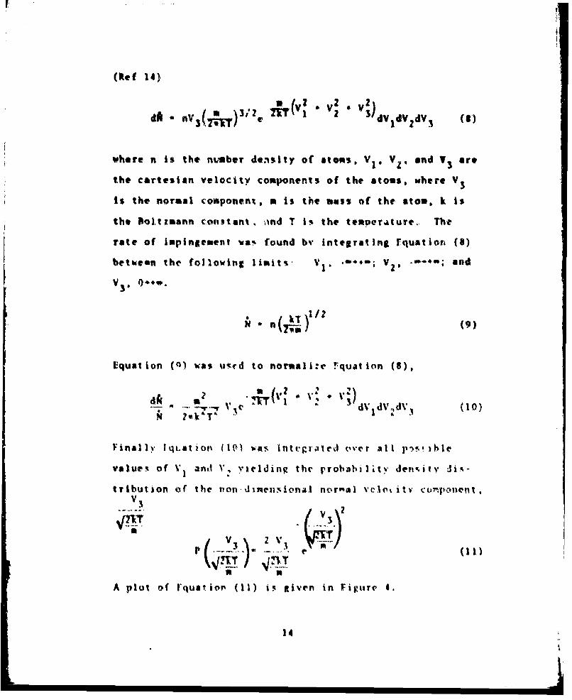
(Vef 14)
dA nv3 ( 7 . 3IZ 0 (Vl • V IMdVldV (1)
where n is the ntuber density of atoms. V1I VZ, and T3 are
the cartesian velocity components of the atoms, where V
is the normal component, a is the vass of the atom, k is
the Bol.tzmann constant, ond T i% the temperatute.. The
rate of Impingement vas found by integrating Equation (8)
betkeen the following limits, V1, "" ; V. "-0.a and
N ( n ) (9)
Equation (0) was uTrd to normali:e !quation (6),
" T 1 dV dV,,dV. (10)
Final I%, qt.ation (W() -Paw IntgrateJ over at I I%); )hle
values of V1 anti V, vielding the probability den.it) Jimi-
tribution of the non-dinensional noral vciotil co'mpo1nent,V3
V 7
a V
A plot of 1*quation (11) is itiven in Fij•tire 4.
14

I,
IC I
Ii
0
IIS
C0
+1.0-.� I.:'
-4
U
4-4
'.4 �.4"
.0a.
0�4.. ..
C) Q .� � I.0 0 0
1$

Wall Interaction Phenomena
The model required a wall odherod fluorine atom con-
centration. Co this end the bonding potential was
examined. According to Emmett (Ref 6) there are two types
of wall bonding phenomena divided into two temperature
regimes in which the mechanisms are predominant, These
regimes are known as the low temperature regime, dominetcd
by Van der Waal or physical bonding, and the high tempera-
ture regime dominated by chemical or activated bonding.
Because of the operating temperatures of the chemical
lasers of concern, this study wae confined to the so
called low te¶perature re;lime which limited its applicabil
ity to temperatures below approxinately 800 K. Above this
temperature the actual transition tc chemical bonding is
Potential Well for Physical Adso_,tion. A %imphe
model was cop,'tructed for the potential well near a sur-
face bas.ed upo>n an adsorption (attrxct~ve) potential and
a repultsive potential a, suggested by Lennard..aone'
(Ref 15). The model is de(cuibed0 Wm'ing COpper Wt an
example. The closest distance of aTrproacý of copper atoms
in metal ii .SK$4 A, whiov that for fluorine atoms is
,.41R A (Ref 16). The equilibriu" distance, PP, must then
be the wmean cf the two distance- or 1.91 A. At this
equilibrium distance the repulsive forces are from 1/3 to
16

1/2 that due to the attractive potential. Thus by modeling
the repulsive force as 40 rercent that of the attractive
force., a well depth was arrived at by algebraically
suminig the two potentials. Therefore an attractive potun-.
tial, assumed tu be W(r). yielded a well depth, aVW' at
the equilibrium position of
atE(NF I - 0.6 W(RE) (12)
No reference is made to an activation energy and in fpct
no activation energy is, experimentally observed for physi.
,a; adsorption (Ref 6). The potential well is shown in
Figure 5.
Several authors have described the functional
relationship of W(r). The earliest of the'e descriptions
(Nef 15) was the simplest and yielded fair results. A%
reported by severrl authors (Ref 17.18, and 19), thi.
early model served a! an upper linit on the physical
attractive force that one might expect to find. One of
the more recent papers dealing with the suhbirct %as that
of C. Mavroyann'. (Ref 20). In his paper, Mavroyannis
derived a formula for W(r) and compared the results of his
relationship with four previou'ly derived relationships.,
thosr of Lennard-Jones, Pardeei. Margenau and Pollard.
Prosen and %achs (Ref IS,1i,I8. and 19). The results of
1,

V
I4 Ge
Up4
hi
Gi
0
I I1j Ifr -J
4 II'
LI -
VP 41
�1
his comparison showed that his model compared as well as,
and in most cases better than the previous models with
data for several atom-surface systems. In addition, the
Mavroyannis model made use of readily available material
properties. For these reasons the Mavroyannis potential
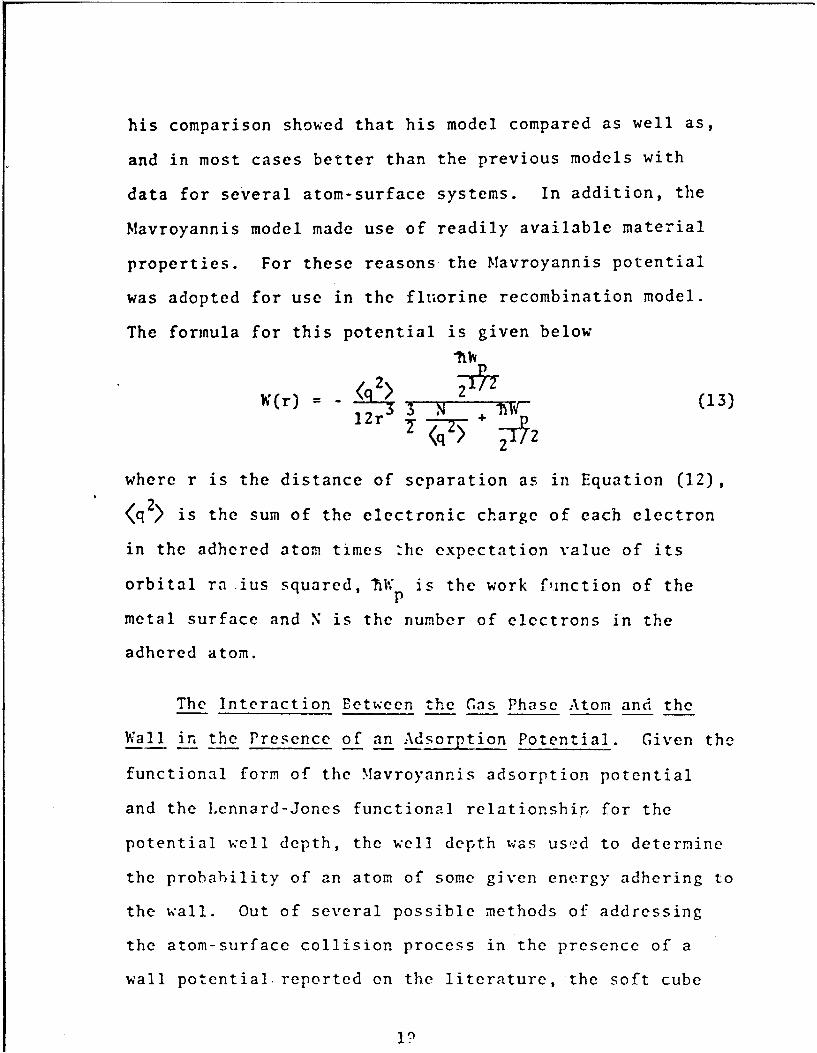
was adopted for use in the fluorine recombination model.
The formula for this potential is given below
11W
Wlr) 12r (13)
<q7 > + Tý2
where r is the distance of separation as in Equation (12),
<q 2> is the sum of the electronic charge of each electron
in the adhered atom times :he expectation value of its
orbital ra.ius squared, TRg is the work finction of theP
metal surface and N is the number of electrons in the
adhered atom.
The Interaction Between the Gas Phase Atom and the
Wall in the Presence of an Adsorption Potential. Given the
functional form of the Mavroyannis adsorption potential
and the Lennard-Jones functional relationship for the
potential well depth, the well depth was used to determine
the probability of an atom of some given energy adhering to
the wall. Out of several possible methods of addressing
the atom-surface collision process in the presence of a
wall potential. reported on the literature, the soft cube
In

model presented by Logan and Keck wa% chosen (Ref 21).
Same result! of thirt model were recently pretenteJ by
Faghi and Keck (Ref 22) and Modak and Pagni (Ref 23).
The Soft Cube Model. As dictated by the soft cube
model, the surface of the wall was pictured as made up of
wall atoms vibrating at a frequency tonsistent with the
bulk Pibye temperature in a direction normal to the plane
of the surface. The overall picture was that of an
Infi-e4te checkerboard with each square made up of one atom
vibrating randomly into and out of the surface at the
Debye frequency, W S. During a surface interaction only the
velocity component of the gas phase atom normal to the
surface wva considered. The use of the normual veloc)ty
component eriable u ata ,orrelikiot, which was not able to
be made u-ing the total velocity in the case of ltw inci-
dent angle atom.!,urf.,ce col.YiPion, Tte gas phate atom
was furthev a.c.!uck t o interact %ith only one ,.urfaceton At.
The variotu' frequentie!ý and 5otential'. werre then mo,<deled
as !Lho•n in I igtare Tm. The ýhipr of the %vll buv'ond the
interact ioi, pj-osil iooi ua of nil impertAit-e. The gaS atom
was *imp,'I) •iveo a!.tI t xionfa Vel o itv a ,-,ve itt Po(lIt.Pann
predicted gx, phikr velrlwoi ronsistent uith the well
depth. A% discuse•l by M1odat aivd Pagni the inter,,ction
spring cnn-r:tait ,* )c* codried hy an exponential
repul.ive potent ial,
20i

oo-%
9-10
IJoe

V(r) C SE LW(RE) e (14)
where r is the position, ' is the distance over which the
Interaction took place, and C and 0 ar- constanti adjusted
to matc'n experfmental dala. The spring constant was
obtained from rquation (14) by differentiation to oetain
the fori:, and evpansion of this force around r - 0 keep-
inS onI:. up to the linear term, H4atching the boundar"
condition that the forcr 0 at r 0 yielded a spring
constant, kI
where 1I %, the .'el! depth. The -1r7 nf con-;tant f(Pr theV 'ur
face Ito %,aN Fivw.n by
cont.N~t itlj Oic 'vi~ rr~kl of'Of Ntr ~iný- " ror~ this~
poin unil O ;e .kol),i on r e'~ it . kt I a r
%iwnple und. e ýo -v Is, " t r "r. A k (1 ',A 1t tV01
p1 a r. rt a Nt or. o( r I tv v
!I
v'-V 3 4 (37V£
where V3 is the Boltzmann predicted random surface normal
component of velocity (see Equation (11)). The Y(O) posi-
tion of the spring at collision was also random but equal
to Z(0) The initial conditions were
Z(O) - Y(O) (18)
V i) (19)
Equation 119) is interpreted to rcar that if the velocity
v were leC,s Than i(f) there, koild halr been no collision.
The collision ended at t when Yt t ,At*1
that pc10inI . if If Z (W(t ))' ) the atoe vas t-apped
and i f ,'12 P4 (v~ 1 t the atom escap(d the well
and avoidr t ! trapp ,
Referrin. Ir Tirure 6. the eqit~aioný ot rotior for tLe
csoiiision yi t,'ess ave given by
M . k. 1.' . (K * k ) 2 - 0
p: t - |
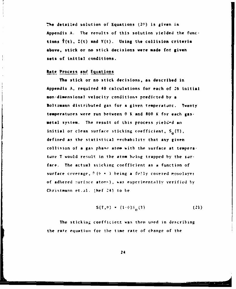
4.Te detailed solution of Equations (2n) is given in
Appendix A. The results of this solution yielded the func-
tions f(t), Z(t) and Y(t). Using the collision criteria
above, stick or no stick decisions were made for given
sets of initial conditions.
Rate Process ane Ecluations
The stick or no stick decisions, as described in
Appendix A, required 40 calculations for each of 26 initial
non-dimensional velocity conditions predicted by a
Boltzmann distributed gas for a given temperatJrc. Twenty
temperatures were run between 0 K and 800 K for each gas-
metal system. The result of this process yiel6-d an
initial or clean surface sticking coefficient, S (T),
defined as the statistical r'robability that any given
collision of a gas pha~e atom with the surface at tempera-
tare T would res.ult in the atom beiitg trapped by the sjr-
face. The actual svicking coefficient as a function of
surface coveraTge, 'ý ((I - I being a fN-1ly covered r1oolayea
of adhered nurfice aton-). %as experinent.IlIy verified I)y
Clristmann et.al, ¶tkef 241 to ic
s(cr,(4) - 00•)• [) (|0
The sticking coefficienrt was then us.ed in describing
the rate equation• for the tine rate of changce of the
24

surface adhered aton concentration by
T*T - ol St F 8FC(2)
where n is the surface concentration and is the rate ofSF
impingeuent of F atoms as described earlier. The depletion
of the surface concentration described by the last two
terms of Equation (42) was given by the thermal desorption
rate, 4, times a surface coverage 0 (Ref 6) and the detach-
ment caused by recombinations was represented by a steric
factor St, the surface coverage 0, and A V The thermal
desorption rate used was that given by Classtone, Laidler
and Eyring (Ref :5)
ED
., kT (23)
where C• was the number of surface sites per unit area
(metal 5iirfasýe atoom packing), h the Planck constant, and E
a desoiption energy. The packing used was that of the t*ace
centered cubic for all surfates consideced (Ref 26). The
steric factor St is the ratio of the gas phase-surface
adhered atom collisions resulting in a recombination to the
actual number of these collisions.
The surface coVerage of interest in Fquation (22) was
of course that of the fluorine atoms. Since the actual
2s

number of adhered atoms depended on the number of available
surface sites, the presence of Adhered atoms other than
fluorine effectively decreased the surface area available
for fluorine to adhere. In this light. Equation (22) was
rewritten as follows
d (n , (S( 4t - 4 ( 01F( - ST) F IF - SiFeF (4
where *F represented the fluorine surface coverage and T
represented the total surface coverage which included cther
as wel! as fluorine atoms.
To quantify PT * rate equation was written to include
the effect of any diluent which might have seen present.
This rate equation was given by
d (n 5}-- -"( 6DeD (25)
where Uquation (2ý) reflect% only one subtracting term,
that of thc'na.l ilesorltion. tor one diluent then,
OT eF- a aF 4( .ming molecular species do not adhere.
Solving Fq•uation (24) and ('.5) for the steady state
condition yielded
1 ((26)
( )
26

pl s , J , (1 n (27)oF St
Further, solving Equations (26) and (27) simultaneously
0 F- (I rD)~~I 0 (28)F~ do Do(
where
SO,1 (29)
0e - 6D ( o0)
() d nd (P D)o uere defined to corresipond to the actual
coverages of one in the absence of the other.
Having .soivvi for the .urfact vovvrage of atomic
fluorine, the reco'1binatiust, rate, vR, u's given 4arbl I'•
VR (31)
Finally the recoo|,ination cofficient, Y, defined as the
ratio of fluorine aton %all collision- tesulting in a
revoohination to the total number of fluorine atom wall
27

v R

III. Low Pressure Plje Flow with Wall
Racoabination
A simple model of one-dimensional volumetric fluorine
depletion applicable in low pressuir pipe flow v*s
developed to simulate the Ultee experiment (Ref 13).
Ultee Experiment
The Ultee data w-ere taken in the experimental apparatus
described pictUT'ally in rigure ?. Gas of known F2 concen-
tration and a diluent (arton) flowed from the gas source
into a microwave di'charge cavity where the molecular fluo-
rine was dis'ocnated to atonic fluorine. Measurements
taken at the exit of the ýavity without the test sample
tube attached shoued that approximately 10 percent of the
F2 was dissociatrd. This fixed the gs- mixture of F, F2
and Ai at the entrance of a 75 co X 1.1 cm (I. P,) testsample tubee Rade of variokis catalytic neutals. If interest
here was the' ni-kel sample. the pre'srtre drop acru2- the
Aample, the equilibritim temperatutc of the -'expc ard the
flow rate of the a •erre oninured aad recorded. An ISR
spectrnmeter locAted at the end of the tett. sa•rri Yielied
Information from which r and F concetritrat ions %ere calcu-
lated. The ga5 then left the teot ajptratut thiough the
pumping sv'tem, For each data point the nyiter was
allo~ed to come to equilibrium at the paiticular
29

1 � r7zZzz�Ifit a
�ILg 4U
-i
**1�44 UA' U
-. 4I.Up.
wI I,I 'II S.D
..uI -
7;,j4i t.r'J 'IN I..
"4
aV. 14j 'L-
- '4
Th
30
b�-- -- �-'

temperature of interest, always eKepinE s constant initial
pressure and flow rate throughout the expertmenZ.' range of
temperatures.
_______ý made?Analytic. -oe
Under the assumption of a one-dimensional dependence of
the concentration on axial position in the test sample, the
equation of the process was written as follows (see Figure
3)
dn )kT /(
where n is the numper density,, x the axial position, r the
tube radius, * the recombinatior coefficient, U the flow
velocity, and n (kT/.vrnml the vatz, of ippingement.
Equalio:n (31) has an analytic -.olution under the assumption•
of a constant rekumbination coefficient y and An initia~l
number density n
-- - - •( 3 4 )n0
Fquation (34) can be u-evd to dete,'imine, an• overall effec•tive
recombination coefficient.
Since the recovwkin;,tion coefficient, as dec:ribed in
Section II, d.pended on varioti, parareterr %,hich changed
with posbtion along the test ta~rle, wore accurate
3!-

I 6
'7 '.
C-
0*1 6°
• h t-
" @6N C
oS
III.II I
I -1 I
, • j_
La
1 *1
(44
S..
u I I ! 'i

simulation of the actual experiment was made by a step by
step solution of Equation (34) for an axial grid spacing of
Ax.
n(xi + Ax) "4 j)Ax k )/2
n(xi) = e (3s)
where the values of y(x) and n(x) were calculated at each
station to predict the change in the number density to the
next station.
Applicability Criteria
As a measure of the applicability of the sole assumed
dependence of the fluorine concentration on axial position,
the characteristic times for diffusion and depletion can be
compared. A typical time for diffusion to negate gradients
can be represented by the relaxation time for diffusive
equilibrium in an enclosure of dimensions r (Ref 27)
LD=FF 2 3r2 (36)tDIFF -D - X6
where V is the diffusivity, X is the mean free path and V
is the average molecular velocity. This time can be com-
pared to the time necessary for destruction of all, the atoms
in the volume V by recombination at the wall neglecting the
effects of diffusion. The depletion time is given by
33

nV __(7
Zn I S
where S is the wetted surface, ror validity or the one-
dimensional assumption of the concentration
tRtC > DIFF (38)
34

IV. o"m !!r son Theore ti CalI Mode1
with !Ljl.er'iental Data
Stickint Coefficients
The solution of the equations of motion for the culli-
sion process were integrated over t0:e Solt:mann distribution
given In figure 4 to obtain the sticking coefficient, S,
for fluorine, argon, and helium for three s*rfaces represen-
tative of fluorine laser no::lc materals; gold, nickel ard
copper. The results are given in Figures 9, 10. and I1.
Comparison of the figires in light of the effect Qf diluer.ts
ni re corhiFrt ion rste- (lquations ( 'S through (11)) x%
discussed earlier inilicateti that argon, when used as a
di Ilent , 5honilq lhave ain appret zlih'( effect on the recoot,,ina,
tion rate G(f fliorine, %hhile thr hel',un prohahl) uoult? isvt.
FurthVI nent •air• (,f the h'eli,- dIII Wint -.N.tc' I Rade % Mter
tilteir (Ref 1.1 ' t),'o: -' , a %lightly higher reton,
b inatior. r ~t ewr ~:v oc c iirt- on co ,ýr t han *t,, nik-le
I xamf.i i v 11 ' iv I ,Ir P t h i ,zP-. , t'i t. n!0 I 11.
a 1i 1F,1,t 1 1, igt v V t i ý , I Oli . ' f I 1- ' i c t it t 1 1 v o l I~ A Ilk '
coppli r.
C i w f P ;~ 1'.!vi C.1 I Ik. I1 I I on I t V
The r!hy si ; *fl t pi~ Jar~c, t t oAf tht 1ý t V v %, v' ,' tlv'l .iit
g iven iri 1 A- le I annd the cov-pu t. t,;,vaI 1,,fr.,-c vP , 1 Tr. 1 '1Ven
in Iato I I I . 1ý%inF the &Ip)it ' -bil iv y ,y ate? t fr.'ro Yqp,,
tion (F ) at w !', fo•r nd tha t v'aI%.u It t nI 1,a Ncd tin t ne

I
I /I 0 : t
,.,/ /,0Ii
gI / /1i : ,,,II / I?
'I, ,I "f
/t/ / 'I...
/ 1 I, P.,
/l,ii/
L9 AA.
S. ... .. .1 . .. . ....... •1 . .. . .... ... ..I . . . .. . .. I.. . . ..... .. '.... . . . -A. .. . ....,• ,

-�
I II II II II I1 1 2 C
I II 'CI U 0
�j.4
ii I/ I Si
U
I I
'I4%
S I ,J t.�
// I U
II I I -5
/ I
'I /
/�55 1
/4- // I
/ /4-,1 I.
-- 4-
.1. -
.4.4 (.
(S C-;,0
� �i i�:c �. j
3;.

r
I V
I.0
4*
41-. 4
..- U
'4'
� '4'*
�.
c.-� rb -E
Iii �' 0 I- ..MU
hi AlIII 1 4*IH U)
2'I
:1'. I.1.
ii1J !;
- - c---- -- -
----- -.
I-' C,
C, 0

one-dimensional assumption for the test conditions of the
Ultee experiment were applicalle for a recombination coef-
ficient as high as 10' , Thus the one-dimensional assump-
tion was good for *l1 available data points as will be
shown,.
Table I. Physical Parameters of Ultee Experiment
PA AIi. 1 1 R YALU|
PRESSURL Z.7 TORR
F401K V.LOCI'IT la0 CM/sec
HOLE F(CTIO, ATSAMhPIJ UMTAN17
(F) 0.02i !0.0
AAr) 0..0
"L F TPIATURI. RAC(4 0 to 400 1C
SAIPLI kv•41 RIM. N 101 Fm.t.
SAMl N't. I I. i. V, C"¢I
Conjiut 1. a on ýh r 'v I ~i~i o X arv~( ! were. ppr,
fornedl for c -. i i,0:• •t• b( lh •e •. k, ~e~ l!,~~'( l d]az..
The i•v!ult, of ¢ ccrpu ta i•nf. a pRir-t,, krn 14igtte
. houii) n .•, v e IZ iv v' ! h ient Int' v ilPIl tn, a! t 11 ,e
end of %he nit•-0l' "v'aple tihe OV ,t J rTan.e of t ýt.i z ,,tatuo
c•h ',)-ýc in vrtti to h!iv"v *,hc r',,ld at':h t tiv dal U 'vrc 1h
de.ci pt i•,• r< '1.• *t.. 1 d ( • , ai~d l he .• , •l<, fl•1
;M 1Cft0"
:-~ ~ ~ ~ ~~~~~1 Air l lllI-•IIII

06
40 low.
01
1 .0 IV
WN.
S444
0 U 1on. r: c
of 0
0' a4l~kK)"IdAWXV -
404

St (see Table I1), 'The desorption energies required to
match the data were found to he similar in magnilude to
those for other gas-surface systems reported by Emmett
(Ref 6). Further, the choice of the desorption energies
yas rather clear since a higher or lower energy caused the
curve intersection with the temperature axis to shift to
the right or left, respectively. Also as an additional
indicator of the correct choice of desorption energy, a
higher or lower energy caused a shallower or steoer slope,
respectively, although this effect 5as not as pronounced
as the intersection shifting. The effect of varying the
steric factor. St, is shown in Fitute 13. A steric factor
of 0.1 seemed to best fit the data.
Table 11. Computational Parameter.s
PARNMUTIR VALU|F
RAr 6.63ZS5 X 10 £
ar3.-431 X 10 23mF ~~3.35851 ,li t
(!I) .1.,4 l 4 I D erg
0I.1) Ar 1.14.3 X 10 ' -erg
St 0.1
(,So)I !ri g,.,e 9.
{Ko Ar Figure 10.
41

100 -- - r
/. 1
WI0
Iv. -
42

By using the model, region% of the data were inter-
preted and labeled as shown in Figure 12. Region A (0 *C
to 40 *C) is that region in which the -#all reaction was
dominated by the presence of adher*d argon atoms
"*poisoning" the recombination process by not allowing free
surface site% for the fluorine to attach. by use of E~qua-
tion (30) it can be seen that prior to reaching some acti-
vation tempertture for thermal desorption (i.e.,
6D - (So)DMl)' the argon conpletely covered the sutface
therefore rendering •P equ .1 to :cro. As Ctc temperature
rose the thereat desorption b.'mcane important and the argon
began to allou portions of the surface to be left vacant so
t.. z .. osr coult attach and subsequently recombine,
In region t, (40 *C to 19S ".) f - w,• insignificant as
compait.d to fSo)F %.rthuý,, the %urface coverage was deter.
mined primarily Iv St and {S so that Fquation (.9) could
be approxinatet! y
o
Pinally 2n region C (19!, "C to .410 *C) the desorption
of fluoripir wvi- ac'tivate'i anil evtintu•yly doeinateJ the uall
teA(t ion.
At this po.nt it i% of interest to aention Figure 14.
Equation (34) *ta, used in coniuiclit n w'itio the 1 r1te, data
43

c)r
I|I .. . ... ..... . .. . . --
ItI.E
c a*
s f-444
0•
/U
'-414
(J.) •'+, :• +<:+,,
44.g

TV
to obtain an average wall recombinction coefficient. The
result of this computation is given in Figure 14. The
unknown regiin refsrs to the temperatures at which no F was
detected at the exit of the test sample. Thus, at an aver-
age y of approximately 10 all the detectable F had been
removed from the flow by wall recombination, This seems to
indicate that vithin the range of the experimental data the
assumption of one-dinensional depletion was applicable.
Equations (26) through (30), however, show the dependence
of y, on the local number density In the 4F terns. The
maxioum recombination took place at the entrance of the
test sample where nF was a ma.imum. Figure 15 shows the
temperatere dependence of Y based on the maximuim number
density. Using the maximum y criteria the experimental
data range still fal)A within the one-dinews~ional assumption.
14ore important, huoever, is the capahaitiy of determining
the actual temperatuire and number density dependence of Y
using the model. Without the nodel the htst one could do
is to dete-mine an averra - fion )ig ure 14 extrapolited to
a waxinum. CXleaiI1 the actu1l vaxiaue is neafl', :to or"
or Magnitude higher than %ould be esttvtated h.thout the use
of the iodel. This mistaken naxinur i' in fact what was
reported by Ultee (Ref 1.). A -et of Naxinup rccurbination
coefficient curves for several gas pressure- for 90 percen?
dissoriateJ fluorine is given in prrendix 11. While the
4S

CALCULATED~ WSOA
DILMUT-CALQtAA7tD FELl
FRX 14L IUM- - -DILLVET
DUA (MIa- 1o E.XTRAKCLATEDt~
w
4A
.600
90%. Arjran ' .ec~int I I oh kiiJ 1 AM 1 14rine
46(

I
curves for 90 percent dissociation are different than would
be predicted 1y 10 percent dissociation the characteristic
trend for incre3sed total and partial pressures is the
'am.,
Used upon Figure 11, it is preditteJ that in a
similar test run with a helium diluent region A would
*Ather be ncnexistent or greatly reduced from that in Figl
ure 12, while region% 3 and C would show no :hange. The
maximum r.•comh~nation coefficient with a helium diluent
should roughly correspond to the curve in Pigure IS
represented by the d•ahed line.
47
m=M

_r
V. Effects of Recombination in
Chemical Laser .ao~zls
Flow Equations
A two dlmrns.onsl, steady state, laminar, explicit
boundary layer code was con.;,ructed to approximate nozzle
flow. The coJe was constructed for the purpose of demon.
strating the applicability of the we!! recomoltnation model
to real flow system%. The governing equationt are as
follows under the usual boundary layer assumptions:
COXTlNrl•TY:
EMO F., TIM!
Pui )U AP, MI •, (41)
m 0 (42)
Me41NFRhMY
sp c.Il s
.. N, F R (.2
p U 1 -wi
(431)
43

where x is the axial position, y the tranSVerTe position
(see Figure 16), ;, the dcn.•ty, u the x. onpi|nent of veloc-
ity, v the y-component of velocity, P the pressure. P the
viscosity of the mixtule. of) the rate of produiction of
species J, Y the diffusivity of specie j into the mixture,
F the mole-ma~s ratio of specie j, cp the specific heat at
constant pressure of the mixture, hi the enthalpy of specie
i. and k the thermal conductivity of the mixture. Von Mists
transformation for compresible flow %.a* u.sed to simplify
the equations for in'ertion into the code. Introducing the
stream function
" Pu; " (44)ii
Lqiiation% (41). (42), and (43) become
3t'I d1ip • I (4f #
311 1 dr'.1i
;7, j ' .U
)V _I
€ P1 i(46'
lhc' dk f f oreni. eqiiat ýý t-- I'int ý1 t ,r (Jr0) *"l J '
a ire ir~1u~Ied in Aipetidix L.
S41

04
",.A r•,,. zz j///d4"'e:Z¢ /
II
- -~~ I X C~f-\". '
I .A . ,!:\A
S '4

Thermodynamic Properties
The enthalpy and specific heat at constant pressure
for the individual species were calculated in the form of a
quintic polynomial with temperature as the independent
variable as follows:
h. b2 T3 d4 Tb aT + T + cT + dT+ e + f (48)
C
Pia + bT + cT 2 + dT 3 + eT 4 (49)
where the coefficients a, b, c, d, e, and f were taken from
Reference 2, and R is the universal gas constant. The
density was calculated by
p P (50)RT FF
Homogeneous Reactions
Two free stream reactions were considered, that of the
dissociation of fluorinc and that of the recombination of
fluorine.
DISSOCIATION
KF2 + M * 2F + M (51)

RECOMBINATION
Kb2F + M -• F 2 + M (52)
where M represents any second or third body, respectively.
Here the dissociation was defined as the forward reaction.
The forward reaction rate used was
K = 4.2 x 10"11 e-(33000/RT) (53)
taken from Reference 5. The backward reaction rate used was
K 4.716 x l01s (1250/RT) (54)b T
taken from Reference 28.
Transport Properties
The transport properties for the flow constituents were
taken from Reference 29.
VISCOSITY
2.6693 x 10 (55)
where P is the reduced collision integral curve fit as a
function of kT/ci and M. is the molecular weight of species1
i. The values for a i, the cross section, and ci' the
52

maximum energy of attraction between colliding molecules,
were taken from Reference 30. The viscosity for the mix-
ture was calculated using
N XiJi (56)
where X. is the mole fraction of species i and
SMi -1/2 1 1/2 M. 1/4 2€i _I 1+ l) + (S. M•.I(7)
THERMAL CONDUCTIVITY
The thermal conductivity of the flow constituents was
calculated using the Eucken approximation
i =(C + -R (S8)
The thermal conductivity of the mixture was calculated by
N ,Xiki (59)~~X i~ ~ ij
j=l J1
where ij is again given by Equation (57).
53

DIFFUS[VITY
The diffu.sivity was calculated by first calculating
the binary diffusion coefficient by
.0018583 W,Pt., a P (60)
Q was curve fit as a function of kTf/c, where
S * 9ti /2)I (61)[iii
mid 0 was given by
Fcr calci*2atrc Q-' ~Jil~f;u,~itv of rthe cornst iturnrt i.mo the
si-.ktnrc -thce .foihn.1ing s~tej .d
Two' 4' c,,O±
C., V.. (t.3)
1'hre Sper iw.,
N 3 ,a ]'' ) •~ .V , ',l Il i0.) *1$4 p....
P2 • * 4

with similar equations for V and P30 (Ref 31)
Hore Than Three Species
For more than 3 species only trace species were
bandled. Krnen more inan 3 speCies were p'esvit.
the first 3 were given by Equation (64) and the
remaining trace species by
i .- (i (l xi) (65)
Rounda~rZ Cond ki i.,ns
The no 4lip wall condition for velocity was used. The
tCerperature at the %all uas :sFec.ified either as some con.
stant AluC OT aSS a fu,;ction of po1ition along the *a)l.
The uall cor,.'ition', for ý.ont)n~tratioit of atonic and nolec-
ular fluorino %.ere giver. -,- fctl~o%,, ,i. a functien of the
rccorhinat~vi, 4orfficivnT (deiication included An Appendix
C).
FIn L I i. I. 7T- 1
hu cit- the' i. I �. Z fI ao: Ine c:xc'e•t'f T t r I¢ , T, I )CH I ,11, %,1
c n1cuI thce , Ir er ,- ! --,cx1• I x ure I" f u ('•7 v
5~in((, the rc% (AI kýJ t.p I . it I t uI i or ef' (n~,¾,L
dc~r-ivndp ui~l' v'n v' lhivFý at tlv upst rear, T , 'lhe

r*,2CL
ICEL
I W EL
WU
Figre , gundrF ondlio Nozeic~aur
2 £A , 1.12 CE1
The nozzle center! i~rc coinditi cns uerc hantsIc! by svrnetritial
refeCCT ion.

The domain of the calculation was from an axial posi-
tion, • - 0.0 at the nozzle entrance to R = 0.4 at the
nozzle exit (see Figure 16).
Results of Nozzle Flow Computations
The boundary layer code was run for predictions of the
effects of recombination on laser nozzle flow. The pres-
sure profile and nozzle contour for a representative slit
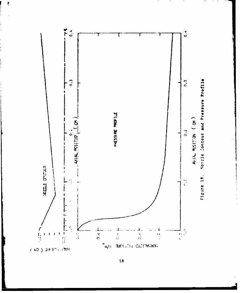
nozzle are given in Figure 18 (taken from Ref 4). While
not the most commonly used slit nozzles, it was similar in
size and basic contour. The input conditions for these
computations are given in Table III.
Computations were run for three wall catalytic condi-
tions: (1) noncatalytic wall, y = 0.0, (2) fully cata-
lytic, y = 1.0 (Ferrell et.al. conditions) and (3) step by
step computation of y based upon the recombination model.
The results are presented in Figures 19 through 28. These
results, as mentioned previously, were based on the assump-
tion of laminar flow. The highest Reynolds number based on
the mome-ntum thickness was approximately 65. This was well
within the laminar regime as transition to turbulence
occurs at around 360 (Ref 32).
Velocity. Figures 19 and 20 show the effect the
recombination had on the velocity profile at the throat and
exit plane respectively. As can be seen there was no
57
S•FTP' T1
I I
/ I S'" . . . . . . ... . . . ... ... . . . . . . . ...... . .
( • lieI'•., ,•ta

'4-3
0
.1d0 04
0
ji IIC4-
-4C) )C) C14C) C. C) C> C 0 CoC) C0 C) 000
59

r--4
"4-
C))
(4-4
0
$-4
LiL)
r 0
I f If
C, j
600
major difference in the velocity profiles, only a slight
lessening of the velocity gradient at the wall with recom-
bination, decreasing the most for the case where y = 1.0.
Temperature. Figures 21 and 22 show the effect the
recombiantion had on the temperature profiles at the throat
and exit plane, respectively. The throat profile showed
very little change with only a slight steepening in the
temperature gradient at the wall with increasing recombina-
tion. The exit plane profile, however, showed a more
dramatic effect both in an increasing slope at the wall and
a shifting of the profile near the boundary layer mid-
portion.
The overall wall effect appeared to be a slightly
increased heat transfer to the wall due to normal conduc-
tive heat transfer (see Figure 22). To this should be
added the heat released in the recombination reaction. For
this case the temperature was assumed constant along the
wall as indicated in Table III, but an actual determination
of the nozzle wall temperature profile should not neglect
the role of the energy of the reaction. This energy is
dumped directly into the wall as indicated by Meyerson
(Ref 33) prior to being either conductively carried away by
the wall or recoupled into the flow through normal heat
transfer processes. This additional heat transfer turns
61

r
V'4
I -r
4..0
-4
K I a..4.'
'.4
6-4
I 1�'"4
I qqI -Th �
I.' i..4,I (a
,- �4 -:t p 3 -
4."
* .'v -4,1..
4',I a
.4 I '4
.2 0 . .2
0 CaC.( �J:) �

r
II
- -- a- - N -
- - - �
4%
a
A� .-
- 0I-
p r�.I"4
I ,*
I f �I jI I . V
I...
* ,... C

_ -. _._.._
out to be significant, tip to threec times the~ normal con-
duction as cmn he sken in Filgurc 23.
Table Mi. Input Conditions
PARA'srTER VAU
PRESSIPRI. 760 TO~R
TE,~A~~ 'RI 0.0005
.,xI I
'The rifect or.ne t t.' Tmnd' o 1'. A on' of ttý.c
prof~ile iK intrtcr :1 iig ;,t vo l, !,c v-,prvta t ir. I r,,.er
c~~i' ~;'~~)tIn~.The typ~ic.f vif-cowu; heazng &dis-.
A 1" t 1ý'r l I ic:~ o" r- -r a~ f c r
64

44ý
AL

Chemtical CImsi.su*, cn The effect of recombination on
the concen Iratacra Tr4fi'Ies %as of ncst interest and is
examined in Figures 24 tJirough 2t. Figures 24 and !S
give the profile. at the throat And exit plane. respec-
tively; Figure 26, 'how's the depletion of' and growth of
F 2 with axial pci Iion along tuo strean functions in i''
norzle; Figure 2' show- the ioss of 1', -ind Figure 428
tains the rvecobi %a: icor ct'efficient a-. a funct.ion of ',Kial
position. A)ifuY Figtvtc A and ŽS thov a differere
betwe(.k t!(: :',,a11,v aat vzrsu- tht,' .odel , it is
notntv..a•H1', cof i Jxffe--rrrc tha;, the one and a half
order of ,-a.-t¶O tffrrvr, 4 e in 0.v reccnn=ination c-effi-
caent],. .t r F t A e The -a,,,.; for thx!; can r-rc foud
b4 an 2 2 "1 c. - i - an rI -
tha' (¶ .. * r.

r
I 4.4
I
6
(4 0C �
(4
� 0
IC.
-. 4
�- ,.
1; C
I 2 , 2
1 .4
I,.
e I
I � �
L

V
________________________ "4
C
p49
'a-4,
4-
.4'I
-4
0 0I-
C**'
-�
;z4
*1'aj tt� LP.
Ii
) 2 1-
1...
-
C t� ) .��'!>

IWO
to pI "4
4e *
I b a
I 1 0
toi,
I 9,
1i6

r� -
0
I
III 0
I I-,
I SI I.
-4
I wI S.
6V�% C- .,
SI-
*1
5!C
uJ
-J K .45"..
-¶I
(I J b.
I -'
C0 *
I I
t 12

0.07 ~ Tr- F
I.-t
4r
- - - , • •A , A n

Finally, rearrangint the terms slightly
2 (nF)CELL 2I "IT1177
Y (7 F
Thus, the actual rate at which F is depleted from the
RIst~* 5s dependent on both the diffusivity and the recom-
bination coefficient. Fxanination of the, two terms in the
denominator of Fqration ('0, yields the figures in Table
IV. The table shows that while the Y's differed by T, the
actual, derleti..n %as limited to a difference of only S at
the exit and 4 at the throat due to only the terms in the
denominator of Lquatic,,n ('0). Coupled to that limiting
influence, tht,, actIa F aton concCt1trt1o in crinIL. 2 linited
still further the idtfterence in th1 tuv solutkon- so that
the final differenccs •,erc rvduced fr,,rv I- to approxinately
'J.4. Thi. ratio is verific'd 1r,• 'irurv 2'. where the total
anoiint of 3tcI'i fhMiri•.e rv.%-•ed by recorOhinatior. va'
3: pr-rcen, ct'lo Aýret •i, 1$ ,(rcTer•t rt c, vcd ,hc "r 1. .

IA
cii
Su_
0 -0
ICC
C. C , 40 •,
P C
H L, il " *
r . • - -4
.. ~ . ..P -. *44

VJ. Conclusions ald Reccoendati>ons
The present %ork dealt with the construction of a
theoretical model for the heterogeneous reconbination
reaction of fluorine at a metal surface. Using the Rideal
nechanisn the reaction was divided into three distinct
procesies (1) the bunding proccss of atomic fluorine to
the wall, (2) the collx.ion and reconbin~tion process of a
ras-phase fluorine ator •nuJ a bonded fluorine atom and (M)
the rate iroccs5 at v.hiO. the 'onJing and recr•.,nnation
takes place centdeving the .urfat. cover~ag. Having
treat ei t-3ýh n.'( ý:c -recr ir ke!-ec! ha i I, !,e'-e isT
flo',u '• a- ,,ýJ • fe .o jt , ,b tl "ýwz takv r ,
6y Dri . I " - ,I i " nirt, i!' li .,r.t Pt c r .a••h -_ ai
(7 4 .44
tor~~~~~~~~~~~~~~ I A arw' 1' ý!'I03101r''ýIC"'

()a loui tesprrature regim~e (le!;s 'IS0 %) in which the
recombi-iation reaction uas poisog~d by argon~ donin.atina; the
surface, (2) a aid-tenpersturt regine (M5 K to 47S K) in
which the argon~ h.s thera~fy dev~orbed and the fluorine
thermal Jesorption was not significant enough to substan-
tially decrea,,k the kurface coverAge of fluorine and (3) a
high teviperature regiar (4"S5 K to !"¶ 1) in i6hich thtrual
des~orptionr~ pa)-J 3 significant tole in~ decteasing the
fluorine ý-urfacv %:everage. 0Klc~ tf.e effect of other 411u,
ents on the reo:reea* j, srucu altv it is predicteJ,
bkdon co~u~~v ý,mjtr'r~ ý,rc tfhýt rhe TeLc~nnitna-
lion ~ ~ ~ ~~" (irf1 01 1Vt~~ n~ f1C.ir%1~' h '(T In tfhe~I IOUI
trpr~~~irt~.~~ I ~ at~-n-, Vt thiri4 reie
(A tt~ (I~ U0, r~ cr;y,
4, f I I f; 1 4 1 . o
1~2~ "f tT¶~ V

I -7.
A 7� A � YA �¶ � -
� � �1 I A
* ,. .,, .�
A, . A
*, A
* A A A A . A ' ,. A A

iun by Ultre should be run with A heliun diluent to fully
verxfy the insignificance vf F 2 attachment. Additionally,
future efforts should be addressed to the problem of
interfacing this modcl Ait h PTroJuction flow coues designed
specifically for analysis of ch.-aical laker no.eles such %s
the one de*cribed in Reference
!! + . . +.* , , '- . - ; . . K *, , .... ,, . . ,. - -, ,
'vv ., , "r , -t, ,• e .t " '; 4,• ,) , t , 2 Y• ', .• :. '. .A , ¢ , ,,:• •,. :Y
- . p, • ""
2. Nm. • • *t p,' ,;& , ,,' t kr~k¶r
.. .0 . . 7 I I 'i k''4
' ' ¶ h t '•I'
f '-L , "' . . ": . . '* '4 . . . . ..4 , '4 • + , t ?
I " t
7 ', , , 4
7 4 4"
,1 \
i

12, Valan:.•, W,, Piranr, P., and Maclean, V. I. "Measure.ment of F[luýrinr ,#Icv Concentrations and Recombina-tion Rates by ESk SpectroscopY." FRK-116, Department ofChemistry, Soston College, Chestnut •Ill, Massachusetts(October 1971).
13, Ultee, Casper, J.. Private Cormuii..•atons.
14. Vincenti, V. C., and Kruger, C. H. Introduction tohvsisal (am Dyna~ics, e'rw York, WI1-_"T67T.,
1I, Lennard-Jones, J. E. "Processes of Adsorption andbiffusion on Solid Surfaces." Trans. Fa. dýr Soc_.et,No. 23, p. 1,14 (19•l).
16, Veast, I. C. handiiook of (Cheml.itry and Physics (53rdre'ition), rli(iTeei-rn 'CriU Tu- I -FTe"Tuh-blT-S-Mig Con-pany (ip.21.
17. Bardeen, J1. "The fiage and Van der Waol Forces at AMetallic Surface." Ph.Fsica1 Review, V,1 $5, p. 727(Octobe 194t-).
18. 4argensu, 11., and rollare., V., C. "The Forces Betw'eenN-eutral %lole-ulc' and %letallic Surfaces." PhysicalRevi,'., Vol t0, p. JZ# (July 1941).
19. Yrosen, t. I. R.. and Sachs, R. G. "The InterrctionBetween a 'tolecule and a I'ctal t -urface." Phy.sicalReview, Vrl 61, p. 6S (January IS42).
20. Mvroy,,nis, C. "'1e Interict ion of Neutral xholecules%ith Is, le•t:ric Surfaces.2" elecular Phvsics., 6, p. S93(1963).
-- "
2;, Logan, R. M., and Kv•4, i. r. "(las~ical Therv for thelnterAt)on of R5 ý!k • i • s th Solid .urface!L.- Journaiof chemitaI Ph !ica. Vnl 40, NO. 17 1. Abo (3%1 1%E
22, Pagni, P. J,, and kttk, .7. (. "Diffu•.ion Throry forAdsorpt ion and De-,orpt ion nf 1,!ý Atoms at Surfacf¢ ."
The ,Journal nf L'•cri•-•l I!it, Vol SO, No. 3. p. 116.2
23. odak, N. T., and Pagni, P. J. "Atom Trapping on Sur-Fmae.." The Journal of C!(rital Phy. ic-. Vol 59, No. 4,I, ~ ~~~p. 2011 ~~~:•-•3:..............
7. . . . . . ...9' I

24. Chr I %tt~ann, WL Scho'her, 0., Frtl. C.. ,ind Neumann, M."Adsorpt ion of Iy'tropen on Nickel Single Crystal Sur.faces." The Jouirn~al of Cheaiial I~y ,VW. 60, No. 11,
25. Glas'stone, 5. , i..idler. K. J., and Eyving, H Theoryof Rate Proces5~e-. Neo York, McGraw-Hill I4T
26. Van dor NOl. A. Solid State Pyrical Flectronics.Englewo~od Cliff's, XeU' Jersey, ir R [ixT I W I
27. Smith,, W. V. "The Surface Pecoembination of HAtoms and011 Raclical[5." Journal of Chenic.al Pýs~ Vol 11,p. 110 (M4arch PTWTT
It. Kur : iu. 5 . C. "La-pp Reaction klotiels for Ansly'is of
and IVngincerirn: la~rratvry-, Redstone Nvw~nal~, Alabama(June 19-5).
20. Mrvirllr J.1 0., Curt k;,ý C. F. and Oirtl. P. 1.Molvctalý. ei'11ýcr o" (.nr and jttiigizid, \e% York,
30. Svehla, F. %. "Itiratev.! V'i'co-iic and Thvinail Con-ductivities' of at 1i9 14,aur- NASA TR-
R13,, .t vnaI \vironatitit, anud 111.c \dq!1nist rat ion
31. MIicklrv, It. S., , P. 1. . cqvct A. I *and
St,,rt . 1'. "Ileat Mat- a.rki t~onvi. ;tit- lrravb er fro
1~ * N.,t ioril ktviko.rv ((.r'nij to'q f,,-r Apro'
Kayst.~ rn i.n ~in *\t~is Trin.fv San ~r t
M~a '." ,okii-nae of h ~',~0 42, NO. 9,

Appenidix A
Solutiton of th rj3za!Ions of Mot~ion
for the GA5-valI Co~lkison Maode)
The gas-wall collision %vstep, hown in IiVrur A.1,
At ttor inrIa¶~rl O~i (oliion I'c', thf. cyIlt itvn If m mc6o;
7~ * K*K Y 0(A.1)
Ic 2 Y '~0(A.2I)
81

The soluition of tquat.ons (A.1) and (A.#') proceeds as
followbi: The soh-tiorh for Y and : i- a.•suaee, to have the
for*
3(t) - A Sin(,t) (A.S)
Z~t)- z Stn•t)(A.4)
In the usual manner, the asuoed .soluticvn. are differenti-
ated for the first Ard second derivative!. and the results
substituted into Equaot•.h (A.1) and (A.*). The result can
be evireised in matrix fole 1y
w* .) kk AI ' ''' 0 (AS)•, °k.I
0 4 )I [
Thu, for i non triviai solution of A and A the matrix on
the lefl "ttst be singlty. S'ettirng the detcrninant to Pro
.3 a 5G )2 ( p1 . I * m a *1 o )
# k k R (A.,)
Solving for the' roots of Uquation (A,6)
( k .n k __ k k t- ., - 0- . -k
(A.,ip
32

whre rr'fers to the soluta; icIf .: v.i tt thv 4 and
7e f T c. t hr -o Iit ion cf . • th th,- The xmrl itu e
ratio ion i- gtiven tby
kw 9 )A -k C I 0 (A.a8)
which gi\v• the frl lowinri avt;, itudr rmt i-i
k
1,2 k. r i
Thuls thr punt Y.• ,.Al --oliat en o( rquat ion%• (• l ar(I (,A.2 i
given 1,v
• €.•* .lg~n ,,l * *l • A~ -iii{ ,," * ~,,){ ,O.11
(At
I IIf Iit o .d n ',, re II) t't .10 r u

Also,
t(0) C cos# (A,13)
i(o). 4)'" (A.,14)
where v is the energy
. ~ ' MIS)
as Indicated in I-quation 07) of the main text.
Let the amplitude ration froum rquation (0.49) be
defiri-d a& follows
A IC11 A (A. b
A2 (A.17)
1hen the r ,st~ it vf %iting the initial rivinditifl%, y•'elds the
Y(t) - (A ioC 1 )ýinu',t , (A Sin 1 Co) Ow 1 t
* (A2 COW(, )Sinuf t " (A ,int )rt!w t (AI18)2 2
84
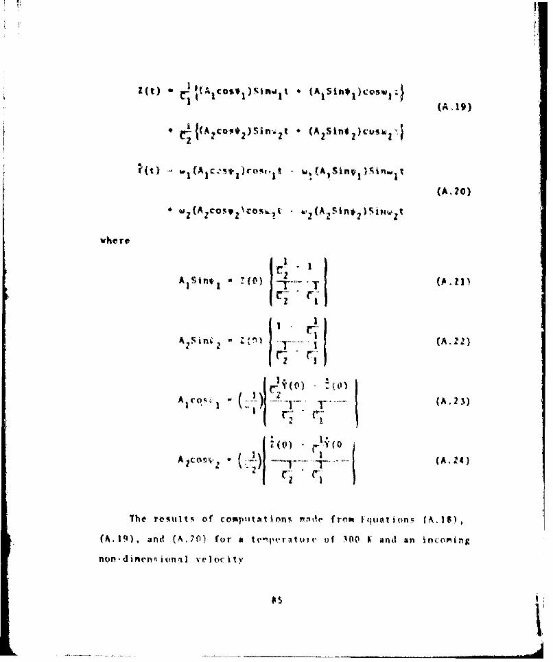
Z(t c &)(A COYS~I)nfw&1I (A1 Stn#1 )cas~w1:
(A Cls*)rol, t- w(A 1 SinV! I)SinwI t1
(A.20)
(Az*s cmý7 - ~.21(A 2Sin* 2 siliw t
A Sin*, .8V A.
z r- Y(O
A~cO'&hv * YJ (A..24)
The teut of comp~itat io'ns "ode fr'ns' I quo ionf. (A. 18),
(A.19), and (A.?() for a tenperilu~iv -of IOP K atnd an inc:o~ing
non -d inc~iv~ionitl ve' oC i y

'0. 3 (A.2 S)
for fluorine on copper Is given in Figure A.Z. ExONatation
of Figure A.2 shows that for a nondimensional Initial ve-
ocity of 0.3 the probability of being trapped (represented
by L1 /L 2 in Figure A.2) i' 50 percent.
Computations made for a range of initial velocities
yields Figure A.3 (note in Figure A.3 that. the prot~ility
corre•ponding tn an initial non-dimewtional velocity of 0.3
is O.S).
A foully of curves similar to the curve in Figure ,.3,
for a range of tem;,cratures. from 0 K to 9OP & onJ Fipure 4
from the meain text, comline to yield the curve for the
initial stkcking -oeffic'i i. s4tic a, the 1,roken linc in
Filgure 9 of the m!hin ,ext for the '.ticling ct'cf•!;c•nt of
fluorile on .o;!'p-r.

2 .0
Ii Trfl*VEATLK - oK
40
INIIiAL. AUILE. AT (tf.%T Of CCCLISILVI (kmw;*s x rr)
Fiir A,.. Initial Anci:v at On r cof Co l i -it'n %-!,
At ~p - O t ct.
P. 1"TLýT~~ - vo
1- 1 purv A. 1. llrcdlat'ii~itv ofi Ator het'ig, Tra~pped

Appe.dix F•
All functions of x, and * were treatcd as the following
fictitious function f(l,,) using the cell nomenclature shown
An Figure RI.X
- i.A,•T*''k T •o~k~"• '
k
VAt
figutrc PA, . Clei~ar~~tr
to f 'it- Iv tkt fl d 1*tt 0 Y v I I 1 h C Ic I

FIRST DERIVATIVE A OPERATOR
Af(x.x) = Af(x,' A) - Bf(x,'B) - Cf(x'c) (B.3)
where:
for all cells except the wall cell and the last cell
A k2
B k,2
C -k 2 _ k- 2
D k 2 k' + kk' 2
*A =1 + k'
*B = ' "k
for the wall cell
A = (k' + k") 2
]B = 1
C = (k' + k") 2 - k'2
D = k ' 2 k' + k'k''2
9A = v + k'
B= + (k' + k")
for the last cell
A k2
B= (k + k') 2
89

C m k 2 - (k + k') 2
D - k 2 k' + kk' 2
*A f' - k
iB I' - (k + k')
'C = V'
SECOND DERIVATIVE A OPERATOR
A2 f(X,- 2 (Af (X'4A) + Bf(x,lPB) + Cf(x,4c)
2
(B..4)
where:
for all cells except the wall cell and the last cell
A =k'
B=k
C = -(k + k')
D k'k 2 + k' 2k
IP = l' - k
'B = + I'
'Pc = •
for the wall cell
A = (k' + k"t )
B =-k'
C - -k "
D = k' 2 (kv + k") - k'(k' + k")2
A ' + k'
90

* ~*(k' kit)
!'Or thp, last cell
A, (k * k')
I A
c -- k'
D * (k 4 '| (k * 'k
- (k kl)
!D FIFFRt•SCU EQUATIONS
1Ising the A operators defined above, Equations (45),
(46), and (47) vere approximated fot the computational
Scheme as followt•,
Uwx X) u(x) Ax~ I dl'
* •{. [ • '" 'i u •* ' (3 .5 "
a t. eV:. {( .•
AF. A2 F
91

T(x*Ax) -T(x) t* U P *
ddi
41 (kou) AT * T (1A)
The pressure was fitted with an analytic curve, thus dP
was taken from the derivative of the analytic curve.
91

Appendix C
Derivation of B dary Conditions for
F &ad r. Concentrations
Theor are two ways of approaching the derivation of the
concentration boundary conditions. One way is purely
anailytic and will be discussed first; another way As to
,exaline the analytic deriyation in retrospect, th1. will be
done seLond.
ANALY TI C
Since the no slip boundary condition for velocity is
used, it would not seem a bad assimption to consider the
region froo the center of CULL 2 to the vail as beinR
N• NZZSZZ2X¶I ' FV'A ' •ijV~l ) 'dyy
Figure C.I. Conservation rquations for Stagnant Cell
93

essentially stagnant. Further the horizontal concentra-
tion gradients are assumed to be negligible compared to the
vertical. These assumptions lead to an analysis as shown in
in Figure C.I.
The conservation of species equation in steady state
is then written
d (grr) " 0 (C-l)
by Fick's law
dnF•s-''J- •'F a');(C. Z)
Thus the Sovorning equatIon is
di0 (dnr)
Integration yields
v -n. A (C.4)
where A is a constant. Iv particulay, at the catalytic wall,
y - I., the %teady !.tatt flux Pitst be eqmal to the rate of
recombination and attachment:
94

I;
Dirfustv* Flux (C.5)
WhOre the 2 accounts for the replacement of the wall atom
detarchd by the recombination. This is necessary, to
maintain the equilibrium wall concentration of F atoms.
Thus
- (Z 1/ dn,(L)
And thus A must be
A *)- mFnF(k ) (C.7)
We n•w have the diffv.rentiaI equation
dnF r kT 1) (C.6)
Assunmig Vr is cori'tant anti iti.e!:atito yields
.yn|(l.)/ k )1'
n (C-9)
Since at y 0 the concentration of F must be (n )CELI '
NUst equal (n F)CL •. Thu5 we hnVe
9S5'
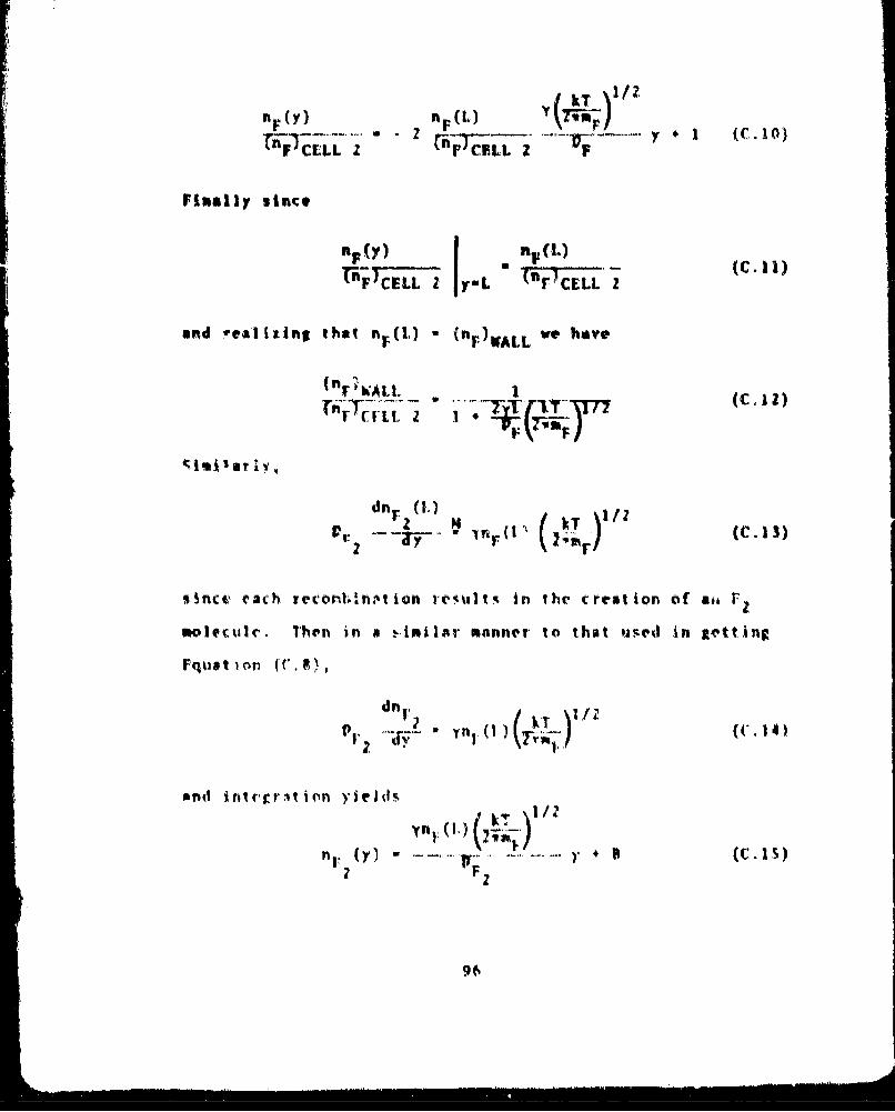
YIkT
Filially since
IFY n,(L
an~d -ealizins that Y"() . nrP1VALI. we"
d n . ( I .) (C -1 3 )
55fnct, rach recont'flM iion re'utsaj in the c~reat ion of ait r-
molecul~e. Then in a i-.imilar viannCTr to that us~ed in se~tting,
Fqan-d o i (Crriin ied
yn 1 .(0.)
n 2 ()F2

Since, again, nF (Y-O) Is (nF )CULL 20 r must equal
(F •. Thus knowing (nF)WALL frou Equation (C..2),
Fme) WALL V y()AL 'T )/2 )CELL 2 (C.16)2', PI-" '7a
RIETROS IECT
StATIrntI fiom Equotton (C.Z)
( n F ) • A L , 1 0 L I I P""_Tr_-'- (C. 1 7)
and rearrangling it sltr',tly yield;
F. (~)uz Zvm)WALL~bT"
(C IS)
Equation (C.1%) iA the iitentlcml statement to ass'.Ung thOat
the slope of the concentration at the wall is li.aear and
*pproxinating the derivative by
dnt: " W L (n!) A..
Thus in retrost',tvt one could have drrlved the boundary
condition,. for Y and V by merely .us-tming a linear profile
at the Wal.
97

Appendix D
To O~rOture nd Pressure
penden ce of the Fluorine
Wall Recombination Coefficient
9,

VI
tin T. t it, W yl i tJ n ý,r fI e l
a.'"
Tep ritir o 46,viunti u r. v NI/i
£I" I I)
I, :1!
... .. ' '•'I It II I u
an iiIiu i.....1~ fl ft i(f

Par 0 1 P ____ f -irit 11 o ' o
IQ r-.P in jnt Il o-i tDiscia o

Ol
3~101

Vita
Captain Eric J. Juwper was born on 14 August 1946, iv.
Washington, D. C. lie graduated f,-os. Hflghlands High Svhool,
North riighlunfl;, California in 1964, and attended the
University of Y'V MPico where ,. rfcaIved a IschlTor of
Science Derev- in Mechanical Fnglneering in June of 1968.
U~pon graduation ho was commissioned a Second Lieutenant, in
the United Stiato Air Force through the RtITC program. Ills
first Air Force assignnent was to the University of Wyoming
for a 4aster. of Science Degree in Mechanical ,•ingneering,
graduating in kugu.t of 1969. From the Ulniversity of
Wyopino he %a% a%%lgne't to the 6,.70th Aerospace 4edical
Re.rarch Labkrtolory at Wright-IP.ttr.%on A'1', Ohio, A% i
Branch iResearch Vngin(r,. Purin, hi, Ktay at tht Aero)ed
Liab. (Cmptaikn lur'er wiorkea in suth areas as Uork environ-
meelt% .1a ero-gravity, viitual recovinaissan'e in flare light
and ha,-e, high at•.itudde flight -uit re'earch, ca-hon monox-
ide toxicolog-, aidd circling line studies from fixecd wing
I r,, tr. In ,hine 197Z. he enteret, thr PhIh program at the
Air lorce ln'titute of technology at Kright.Patterson AFP,
Ohio. Re 't•oprleted ill requirement'ý (or and was admitted
to cfndidscy8 in Jnarnu~y 1914. lie is presently *ssigned to
tht Atr rorce wearons Laboratory at Kirtland AFR, New
Mr i I c 0.
I02

Captain Junper is married tn the ;OTrerY Myerjorie Lee
StenkO of Al~bU(uCtrqle, Ne-W M•iCo. T'iC an! Mmrgr have two
childr-m: it son John, age ", and a daughter ChrlItine, age
Permanent address, 7357 West LaneLoomis, California 9S650
103