disassembly and assembly - · pdf filefuel injection pump - remove (delphi dpa) ..... 17 ......
TRANSCRIPT

SENR9779-03January 2007
Disassembly andAssembly1103 and 1104 Industrial EnginesDC (Engine)DD (Engine)DJ (Engine)DK (Engine)RE (Engine)RG (Engine)RJ (Engine)RR (Engine)RS (Engine)DF (Engine)DG (Engine)
This document has been printed from SPI². Not for Resale

Important Safety InformationMost accidents that involve product operation, maintenance and repair are caused by failure toobserve basic safety rules or precautions. An accident can often be avoided by recognizing potentiallyhazardous situations before an accident occurs. A person must be alert to potential hazards. Thisperson should also have the necessary training, skills and tools to perform these functions properly.
Improper operation, lubrication, maintenance or repair of this product can be dangerous andcould result in injury or death.
Do not operate or perform any lubrication, maintenance or repair on this product, until you haveread and understood the operation, lubrication, maintenance and repair information.
Safety precautions and warnings are provided in this manual and on the product. If these hazardwarnings are not heeded, bodily injury or death could occur to you or to other persons.
The hazards are identified by the “Safety Alert Symbol” and followed by a “Signal Word” such as“DANGER”, “WARNING” or “CAUTION”. The Safety Alert “WARNING” label is shown below.
The meaning of this safety alert symbol is as follows:
Attention! Become Alert! Your Safety is Involved.
The message that appears under the warning explains the hazard and can be either written orpictorially presented.
Operations that may cause product damage are identified by “NOTICE” labels on the product and inthis publication.
Perkins cannot anticipate every possible circumstance that might involve a potential hazard. Thewarnings in this publication and on the product are, therefore, not all inclusive. If a tool, procedure,work method or operating technique that is not specifically recommended by Perkins is used,you must satisfy yourself that it is safe for you and for others. You should also ensure that theproduct will not be damaged or be made unsafe by the operation, lubrication, maintenance orrepair procedures that you choose.
The information, specifications, and illustrations in this publication are on the basis of information thatwas available at the time that the publication was written. The specifications, torques, pressures,measurements, adjustments, illustrations, and other items can change at any time. These changes canaffect the service that is given to the product. Obtain the complete and most current information beforeyou start any job. Perkins dealers or Perkins distributors have the most current information available.
When replacement parts are required for thisproduct Perkins recommends using Perkins
replacement parts.Failure to heed this warning can lead to prema-ture failures, product damage, personal injury ordeath.
This document has been printed from SPI². Not for Resale
SENR9779-03 3Table of Contents
Table of Contents
Disassembly and Assembly Section
Fuel Priming Pump - Remove and Install .............. 4Fuel Filter Base - Remove and Install .................... 6Fuel Injection Lines - Remove ............................... 9Fuel Injection Lines - Install ................................... 9Fuel Injector Cover - Remove and Install (IfEquipped) ............................................................ 10Fuel Injection Pump - Remove (Delphi DP210) ..... 11Fuel Injection Pump - Remove (Delphi STP) ........ 13Fuel Injection Pump - Remove (Delphi DPG) ....... 14Fuel Injection Pump - Remove (Bosch EPVE for the1104 engines only) .............................................. 16Fuel Injection Pump - Remove (Delphi DPA) ........ 17Fuel Injection Pump - Install (Delphi DP210) ........ 19Fuel Injection Pump - Install (Delphi STP) ............ 20Fuel Injection Pump - Install (Delphi DPG) ........... 22Fuel Injection Pump - Install (Bosch EPVE for the1104 engines only) .............................................. 24Fuel Injection Pump - Install (Delphi DPA) ............ 26Fuel Injector - Remove ........................................ 27Fuel Injector - Install ............................................ 28Turbocharger - Remove ........................................ 29Turbocharger - Install ............................................ 30Exhaust Manifold - Remove and Install ............... 31Exhaust Elbow - Remove and Install (IfEquipped) ............................................................ 33Inlet and Exhaust Valve Springs - Remove andInstall ................................................................... 34Inlet and Exhaust Valves - Remove and Install .... 36Inlet and Exhaust Valve Guides - Remove andInstall ................................................................... 39Inlet and Exhaust Valve Seat Inserts - Remove andInstall ................................................................... 41Engine Oil Filter Base - Remove and Install ........ 43Engine Oil Cooler - Remove ................................. 47Engine Oil Cooler - Install ..................................... 48Engine Oil Relief Valve - Remove and Install (EngineOil Pump) ............................................................ 50Engine Oil Relief Valve - Remove and Install(Balancer Unit for the 1104 engines only) ........... 51Engine Oil Pump - Remove (Engines Without aBalancer) ............................................................. 52Engine Oil Pump - Install (Engines Without aBalancer) ............................................................. 53Water Pump - Remove ......................................... 54Water Pump - Disassemble ................................. 54Water Pump - Assemble ...................................... 56Water Pump - Install ............................................. 57Water Temperature Regulator - Remove and Install............................................................................. 58Flywheel - Remove ............................................... 61Flywheel - Install ................................................... 61Crankshaft Rear Seal - Remove ........................... 62Crankshaft Rear Seal - Install ............................... 63Crankshaft Wear Sleeve (Rear) - Remove ........... 65Crankshaft Wear Sleeve (Rear) - Install ............... 66Flywheel Housing - Remove and Install .............. 66Crankshaft Pulley - Remove and Install ............... 68
Crankshaft Front Seal - Remove .......................... 71Crankshaft Front Seal - Install .............................. 72Crankshaft Wear Sleeve (Front) - Install .............. 73Front Cover - Remove and Install ......................... 73Gear Group (Front) - Remove .............................. 74Gear Group (Front) - Install .................................. 76Idler Gear - Remove and Install ............................ 78Housing (Front) - Remove .................................... 83Housing (Front) - Install ........................................ 84Accessory Drive - Remove and Install ................. 85Crankcase Breather - Remove and Install ........... 87Valve Mechanism Cover - Remove and Install ..... 90Rocker Shaft and Pushrod - Remove ................... 91Rocker Shaft - Disassemble ................................ 92Rocker Shaft - Assemble ..................................... 93Rocker Shaft and Pushrod - Install ....................... 94Cylinder Head - Remove ...................................... 95Cylinder Head - Install .......................................... 97Lifter Group - Remove and Install ....................... 100Camshaft - Remove and Install ......................... 101Camshaft Gear - Remove and Install ................ 102Camshaft Bearings - Remove and Install .......... 102Engine Oil Pan - Remove and Install ................. 103Balancer - Remove (Some 1104 Engines Only) .. 106Balancer - Install (Some 1104 Engines Only) ..... 107Piston Cooling Jets - Remove and Install ........... 108Pistons and Connecting Rods - Remove ............ 109Pistons and Connecting Rods - Disassemble ...... 110Pistons and Connecting Rods - Assemble .......... 111Pistons and Connecting Rods - Install ................. 112Connecting Rod Bearings - Remove ................... 113Connecting Rod Bearings - Install ....................... 114Crankshaft Main Bearings - Remove ................... 115Crankshaft Main Bearings - Install (Crankshaft inPosition) ............................................................. 116Crankshaft - Remove ........................................... 118Crankshaft - Install .............................................. 120Crankshaft Gear - Remove and Install .............. 124Bearing Clearance - Check ................................. 125Glow Plugs - Remove and Install (If Equipped) .. 126V-Belts - Remove and Install .............................. 127Fan - Remove and Install ................................... 128Fan Drive - Remove and Install ......................... 129Alternator - Remove ............................................ 129Alternator - Install ................................................ 130Electric Starting Motor - Remove and Install ..... 130Vacuum Pump - Remove and Install (Some 1104engines only) ..................................................... 131Hydraulic Pump (Steering) - Remove ................. 132Hydraulic Pump (Steering) - Install ..................... 132
Index Section
Index ................................................................... 133
This document has been printed from SPI². Not for Resale

4 SENR9779-03Disassembly and Assembly Section
Disassembly and AssemblySection
i02219291
Fuel Priming Pump - Removeand Install
Removal procedureThere are two types of fuel priming pump. Type 1 ismounted above the starter motor. Type 1 is combinedwith the fuel filter. Type 2 is mounted below thestarter motor. Type 2 is not combined with the fuelfilter. Type 2 is used on 4 cylinder engines only.
Removal Procedure for Type 1Start By:
a. Remove the assembly of the filter case and thefuel filter element. Refer to this Disassembly andAssembly Manual, “Fuel Filter Base - Removeand Install”.
Note: There is an option for the three cylinderengine. The fuel priming pump and the fuel filter canbe installed onto the application rather than onto theengine. If this is the case, refer to the appropriateinstallation manual that is supplied by the OEM forfurther information.
Note: Put identification marks on all fuel hoseassemblies and on all tube assemblies for installationpurposes. After being disconnected, plug all fuelhose assemblies and plug all tube assemblies. Thishelps prevent fluid loss, and this helps to keepcontaminants from entering the system.
NOTICEKeep all parts clean from contaminants.
Contaminants may cause rapid wear and shortenedcomponent life.
NOTICECare must be taken to ensure that fluids are containedduring performance of inspection, maintenance, test-ing, adjusting and repair of the product. Be prepared tocollect the fluid with suitable containers before open-ing any compartment or disassembling any compo-nent containing fluids.
Dispose of all fluids according to local regulations andmandates.
g00952432Illustration 1
Typical example
1. Disconnect the tube assembly (5). Disconnect thetube assembly (6). Install dust covers onto theconnectors for the fuel priming pump.
2. Disconnect the fuel return line from the connector(3). Install a dust cover to the connector (3).
3. Disconnect the harness assembly from theconnector (2).
4. Support the fuel priming pump. Remove the threesetscrews (1) and discard the rubber washers.Remove the fuel priming pump (4).
Removal Procedure for Type 2Note: Put identification marks on the two fuel hoseassemblies for installation purposes. After beingdisconnected, plug all fuel hose assemblies . Thishelps prevent fluid loss, and this helps to keepcontaminants from entering the system.
NOTICEKeep all parts clean from contaminants.
Contaminants may cause rapid wear and shortenedcomponent life.
This document has been printed from SPI². Not for Resale

SENR9779-03 5Disassembly and Assembly Section
NOTICECare must be taken to ensure that fluids are containedduring performance of inspection, maintenance, test-ing, adjusting and repair of the product. Be prepared tocollect the fluid with suitable containers before open-ing any compartment or disassembling any compo-nent containing fluids.
Dispose of all fluids according to local regulations andmandates.
g01121719Illustration 2
1. Disconnect the fuel hose assembly (1). Disconnectthe fuel hose assembly (4). Install dust coversonto the connectors for the fuel priming pump.
2. Disconnect the harness assembly from theelectrical connector on the fuel priming pump(2).
3. Support the fuel priming pump. Remove the twosetscrews (3). Remove the fuel priming pump (2).
Installation ProcedureThere are two types of fuel priming pump. Type 1 ismounted above the starter motor. Type 1 is combinedwith the fuel filter. Type 2 is mounted below thestarter motor. Type 2 is not combined with the fuelfilter. Type 2 is used on 4 cylinder engines only.
Installation Procedure for Type 1
NOTICEKeep all parts clean from contaminants.
Contaminants may cause rapid wear and shortenedcomponent life.
g00952432Illustration 3Typical example
1. Clean the external surfaces of the fuel primingpump (4). Position the fuel priming pump (4) andinstall the three setscrews (1) and new rubberwashers.
2. Remove the dust covers from the fuel primingpump (4). Remove the plugs from the tubeassemblies. Connect the tube assembly (5).Connect the tube assembly (6).
3. Connect the fuel return line to the connector (3).
4. Connect the harness assembly to the connector(2).
5. Remove the air from the fuel system. Refer tothe Operations and Maintenance Manual, “FuelSystem - Prime”.
Installation Procedure for Type 2
NOTICEKeep all parts clean from contaminants.
Contaminants may cause rapid wear and shortenedcomponent life.
g01121719Illustration 4
This document has been printed from SPI². Not for Resale

6 SENR9779-03Disassembly and Assembly Section
1. Clean the external surfaces of the fuel primingpump (2). Position the fuel priming pump (2) andinstall the two setscrews (3).
2. Remove the dust covers from the fuel primingpump. Remove the plugs from the fuel hoseassemblies. Connect the fuel hose assembly (1).Connect the fuel hose assembly (4).
3. Connect the harness assembly to the electricalconnector on the fuel priming pump (2).
4. Remove the air from the fuel system. Refer tothe Operations and Maintenance Manual, “FuelSystem - Prime”.
i02224029
Fuel Filter Base - Remove andInstall
Removal ProcedureThere are two types of fuel filter. The element filterhas a fuel filter element in a filter case. The elementfilter is combined with the fuel priming pump. Thespin-on filter is self-contained. The spin-on filter is notcombined with the fuel priming pump. The spin-onfilter is used on 4 cylinder engines only.
Removal Procedure for the ElementFilterNote: There is an option for the three cylinderengine. The fuel filter and the fuel priming pump canbe installed onto the application rather than onto theengine. If this is the case, refer to the appropriateOEM information as well to this text.
NOTICEKeep all parts clean from contaminants.
Contaminants may cause rapid wear and shortenedcomponent life.
NOTICECare must be taken to ensure that fluids are containedduring performance of inspection, maintenance, test-ing, adjusting and repair of the product. Be prepared tocollect the fluid with suitable containers before open-ing any compartment or disassembling any compo-nent containing fluids.
Dispose of all fluids according to local regulations andmandates.
Note: The removal procedure is identical for thefour cylinder and the three cylinder engines. Theillustrations show the four cylinder engine.
g01010637Illustration 5Typical example
g01010595Illustration 6
Typical example
1. Place a suitable container below the filter in orderto collect the spilled fuel. Thoroughly clean theoutside surfaces of the fuel filter. Open the drain(1) in order to drain the fuel from the filter.
2. Use a suitable strap wrench to loosen the filtercase (2). Remove the filter case (2) from the filterhead (5).
This document has been printed from SPI². Not for Resale

SENR9779-03 7Disassembly and Assembly Section
3. Push down against the spring pressure that isapplied to the filter element (4). Rotate the filterelement (4) counterclockwise in order to releasethe filter element from the filter case (2).
4. Discard the filter element (4) and the O-ring (3).
Removal Procedure for the Spin-onFilter
NOTICEKeep all parts clean from contaminants.
Contaminants may cause rapid wear and shortenedcomponent life.
NOTICECare must be taken to ensure that fluids are containedduring performance of inspection, maintenance, test-ing, adjusting and repair of the product. Be prepared tocollect the fluid with suitable containers before open-ing any compartment or disassembling any compo-nent containing fluids.
Dispose of all fluids according to local regulations andmandates.
g01121724Illustration 7
g01121763Illustration 8
1. Turn the valves for the fuel lines (if equipped)to the OFF position before performing thismaintenance. Place a tray under the fuel filter inorder to catch any fuel that might spill. Clean upany spilled fuel immediately.
2. Clean the outside of the fuel filter assembly. Openthe fuel drain (1) and drain the fuel into a suitablecontainer.
3. Use a suitable tool in order to remove the spin-onfilter (2) from the filter head (5).
4. Discard the filter element (3) and the O-ring (4).
Installation ProcedureThere are two types of fuel filter. The element filterhas a fuel filter element in a filter case. The elementfilter is combined with the fuel priming pump. Thespin-on filter is self-contained. The spin-on filter is notcombined with the fuel priming pump.
Installation Procedure for theElement Filter
NOTICEKeep all parts clean from contaminants.
Contaminants may cause rapid wear and shortenedcomponent life.
This document has been printed from SPI². Not for Resale

8 SENR9779-03Disassembly and Assembly Section
g01010637Illustration 9
Typical example
g01010595Illustration 10Typical example
1. Thoroughly clean the inside of the filter case (2)and thoroughly clean the lower face of the filterhead (5).
2. Inspect the thread of a new filter element (4) inorder to ensure that the thread is not damaged.Inspect the thread of the adapter in the filterhead (5) in order to ensure that the thread is notdamaged.
3. Inspect the condition of the spring and ensure thatthe spring is correctly located within the filter case(2).
4. Install the new filter element (4) into the filtercase (2). Push the filter element against thespring pressure and rotate the filter element ina clockwise direction in order to secure the filterelement within the filter case (2).
5. Lightly lubricate a new O-ring (3) with clean fueloil. Install the new O-ring (3) into the recess withinthe filter case (2).
6. Close the drain (1).
7. Remove the air from the fuel system. Refer tothe Operations and Maintenance Manual, “FuelSystem - Prime”. Remove the suitable containerand dispose of the fuel that has drained as waste.
Installation Procedure for theSpin-on Filter
NOTICEKeep all parts clean from contaminants.
Contaminants may cause rapid wear and shortenedcomponent life.
g01121763Illustration 11
1. Thoroughly clean the lower face of the filter head(5).
2. Inspect the thread of a new filter element (3) inorder to ensure that the thread is not damaged.Inspect the thread of the adapter in the filterhead (5) in order to ensure that the thread is notdamaged.
3. Lubricate the sealing ring (4) with clean fuel oil.
This document has been printed from SPI². Not for Resale

SENR9779-03 9Disassembly and Assembly Section
4. Install the spin-on filter (3) onto the filter head (5).
5. Tighten the spin-on filter by hand until the sealingring contacts the filter head. Rotate the spin-onfilter through 90 degrees.
6. Close the drain (1).
7. Prime the fuel system. Refer to Operation andMaintenance Manual, “Fuel System - Prime”.
i02221357
Fuel Injection Lines - Remove
Removal ProcedureStart By:
a. If equipped, remove the cover for the fuel injectors.Refer to this Disassembly and Assembly Manual,“Fuel Injector Cover - Remove and Install”.
NOTICEKeep all parts clean from contaminants.
Contaminants may cause rapid wear and shortenedcomponent life.
NOTICECare must be taken to ensure that fluids are containedduring performance of inspection, maintenance, test-ing, adjusting and repair of the product. Be prepared tocollect the fluid with suitable containers before open-ing any compartment or disassembling any compo-nent containing fluids.
Dispose of all fluids according to local regulations andmandates.
Note: The removal procedure is identical for fourcylinder and three cylinder engines. The illustrationshows the four cylinder engine.
g00955826Illustration 12Typical example
1. Disconnect the fuel injection lines (1) at the fuelinjectors (2).
2. Disconnect the fuel injection lines (1) at the fuelinjection pump (3).
3. If it is necessary remove the clamps for the fuelinjection lines or loosen the clamps for the fuelinjection lines. Remove the fuel injection lines (1).
4. Install dust caps onto the ports of the fuel injectorsand onto the ports of the fuel injection pump. Installdust caps onto both ends of the fuel injection lines.
i02221359
Fuel Injection Lines - Install
Installation Procedure
NOTICEKeep all parts clean from contaminants.
Contaminants may cause rapid wear and shortenedcomponent life.
NOTICECare must be taken to ensure that fluids are containedduring performance of inspection, maintenance, test-ing, adjusting and repair of the product. Be prepared tocollect the fluid with suitable containers before open-ing any compartment or disassembling any compo-nent containing fluids.
Dispose of all fluids according to local regulations andmandates.
Note: The installation procedure is identical for thefour cylinder and the three cylinder engines. Theillustration shows the four cylinder engine.
This document has been printed from SPI². Not for Resale

10 SENR9779-03Disassembly and Assembly Section
g00955826Illustration 13Typical example
1. Inspect the fuel injection lines (1) for wear and fordamage. Replace any fuel injection line (1) that isworn or any fuel injection line that is damaged.
2. Loosely install the clamps for the fuel injectionlines (1).
3. Remove the dust caps from the fuel injectionpump (3) and from the fuel injectors (2). Removethe dust caps from the fuel injection lines (1).
4. Loosely connect the nuts at both ends of the fuelinjection lines (1).
5. Ensure that each fuel injection line (1) does notcontact any other fuel injection line or any otherengine component. Tighten the fasteners for theclamps for the fuel injection lines (1). Check thatthe fuel injection lines (1) are still clear of othercomponents.
6. Tighten the fuel injection lines (1) at the fuelinjectors (2) to a torque of 30 N·m (22 lb ft).
7. Tighten the fuel injection lines (1) at the fuelinjection pump (3) to 30 N·m (22 lb ft).
8. Remove the air from the fuel system. Refer tothe Operations and Maintenance Manual, “FuelSystem - Prime”.
End By:
a. If equipped, install the cover for the fuel injectors.Refer to this Disassembly and Assembly Manual,“Fuel Injector Cover - Remove and Install”.
i02221380
Fuel Injector Cover - Removeand Install(If Equipped)
Removal Procedure
NOTICEKeep all parts clean from contaminants.
Contaminants may cause rapid wear and shortenedcomponent life.
Note: The removal procedure is identical for thefour cylinder and the three cylinder engines. Theillustration shows the four cylinder engine.
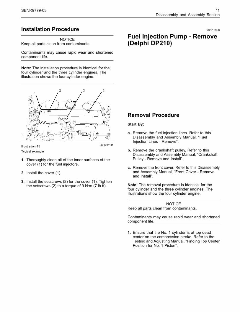
g01011111Illustration 14
Typical example
1. Thoroughly clean all of the outer surfaces of thecover (1) for the fuel injectors.
2. Remove the setscrews (2) from the cover (1).
3. Remove the cover (1).
This document has been printed from SPI². Not for Resale
SENR9779-03 11Disassembly and Assembly Section
Installation Procedure
NOTICEKeep all parts clean from contaminants.
Contaminants may cause rapid wear and shortenedcomponent life.
Note: The installation procedure is identical for thefour cylinder and the three cylinder engines. Theillustration shows the four cylinder engine.
g01011111Illustration 15Typical example
1. Thoroughly clean all of the inner surfaces of thecover (1) for the fuel injectors.
2. Install the cover (1).
3. Install the setscrews (2) for the cover (1). Tightenthe setscrews (2) to a torque of 9 N·m (7 lb ft).
i02216956
Fuel Injection Pump - Remove(Delphi DP210)
Removal ProcedureStart By:
a. Remove the fuel injection lines. Refer to thisDisassembly and Assembly Manual, “FuelInjection Lines - Remove”.
b. Remove the crankshaft pulley. Refer to thisDisassembly and Assembly Manual, “CrankshaftPulley - Remove and Install”.
c. Remove the front cover. Refer to this Disassemblyand Assembly Manual, “Front Cover - Removeand Install”.
Note: The removal procedure is identical for thefour cylinder and the three cylinder engines. Theillustrations show the four cylinder engine.
NOTICEKeep all parts clean from contaminants.
Contaminants may cause rapid wear and shortenedcomponent life.
1. Ensure that the No. 1 cylinder is at top deadcenter on the compression stroke. Refer to theTesting and Adjusting Manual, “Finding Top CenterPosition for No. 1 Piston”.
This document has been printed from SPI². Not for Resale

12 SENR9779-03Disassembly and Assembly Section
g00956204Illustration 16Typical example
2. Loosen the locking screw (5). Rotate the spacer(6) in order to allow the locking screw (5) to tightenagainst the shaft of the fuel injection pump. Rotatethe fuel injection pump gear in a counterclockwisedirection in order to remove the backlash. Tightenthe locking screw (5) to a torque of 17 N·m(13 lb ft).
Note: The locking screw (5) must be tightened inorder to prevent the shaft of the fuel injection pumpfrom rotating. The shaft of the fuel injection pumpmust not be rotated after the fuel injection pump hasbeen removed from the engine.
Note: Put identification marks on all fuel hoseassemblies and on all tube assemblies for installationpurposes. After being disconnected, plug all fuelhose assemblies and plug all tube assemblies withsuitable plastic plugs. Also install dust caps on allof the connectors on the fuel injection pump. Thishelps prevent fluid loss, and this helps to keepcontaminants from entering the system.
3. Disconnect the fuel return line (1). Disconnect thetube assembly (4) from the fuel injection pump.
4. Disconnect the fuel line (3).
5. Disconnect the harness assembly (2) from thetiming advance solenoid (7).
g01011369Illustration 17Typical example
6. Remove the nut (8) and the washer from the shaftof the fuel injection pump.
7. Use a suitable puller in order to remove the fuelinjection pump gear (9).
Note: Do not pry the fuel injection pump gear (9)from the shaft of the fuel injection pump.
g01062058Illustration 18Typical example
Note: The two steps that follow are only required ifthe bracket (11) is installed on the fuel injection pump.
8. Remove the nut (14). Remove the bolt (12).
9. If necessary, remove the setscrew (15) and thebracket (11) from the cylinder block.
10.Remove the setscrews (13) in order to removethe fuel injection pump.
This document has been printed from SPI². Not for Resale

SENR9779-03 13Disassembly and Assembly Section
11.Remove the fuel injection pump from the fronthousing. Remove the O-ring (10) and discard theO-ring from the fuel injection pump.
i02075326
Fuel Injection Pump - Remove(Delphi STP)
Removal ProcedureStart By:
a. Remove the fuel injection lines. Refer to thisDisassembly and Assembly Manual, “FuelInjection Lines - Remove”.
b. Remove the crankshaft pulley. Refer to thisDisassembly and Assembly Manual, “CrankshaftPulley - Remove and Install”.
c. Remove the front cover. Refer to this Disassemblyand Assembly Manual, “Front Cover - Removeand Install”.
NOTICEKeep all parts clean from contaminants.
Contaminants may cause rapid wear and shortenedcomponent life.
1. Ensure that the No. 1 cylinder is at top deadcenter on the compression stroke. Refer to theTesting and Adjusting Manual, “Finding Top CenterPosition for No. 1 Piston”.
g01061708Illustration 19
2. Loosen the locking screw (1). Rotate the spacer(2) in order to allow the locking screw (1) to tightenagainst the shaft of the fuel injection pump. Rotatethe fuel injection pump gear in a counterclockwisedirection in order to remove the backlash. Tightenthe locking screw (1) to a torque of 13 N·m(9.6 lb ft).
Note: The locking screw (1) must be tightened inorder to prevent the shaft of the fuel injection pumpfrom rotating. The shaft of the fuel injection pumpmust not be rotated after the fuel injection pump hasbeen removed from the engine.
Note: Put identification marks on all fuel hoseassemblies and on all tube assemblies for installationpurposes. After being disconnected, plug all fuelhose assemblies and plug all tube assemblies withsuitable plastic plugs. Also install dust caps on allof the connectors on the fuel injection pump. Thishelps prevent fluid loss, and this helps to keepcontaminants from entering the system.
g01062395Illustration 20
3. Disconnect the fuel return line (3).
4. Disconnect the fuel line (5).
5. Disconnect the harness assembly (4) from thetiming advance solenoid (6).
This document has been printed from SPI². Not for Resale

14 SENR9779-03Disassembly and Assembly Section
g01062397Illustration 21Typical example
6. Remove the nut (7) and the washer from the shaftof the fuel injection pump.
7. Use a suitable puller in order to remove the fuelinjection pump gear (8).
Note: Do not pry the fuel injection pump gear (9)from the shaft of the fuel injection pump.
g01062396Illustration 22
8. Remove the nut (10). Remove the bolt (13).
9. If necessary, remove the setscrew (14) and thebracket (11) from the cylinder block.
10.Remove the setscrews (14) in order to removethe fuel injection pump.
11.Remove the fuel injection pump from the fronthousing. Remove the O-ring (9) and discard theO-ring from the fuel injection pump.
i02224700
Fuel Injection Pump - Remove(Delphi DPG)
Removal ProcedureStart By:
a. Remove the fuel injection lines. Refer to thisDisassembly and Assembly Manual, “FuelInjection Lines - Remove”.
b. Remove the crankshaft pulley. Refer to thisDisassembly and Assembly Manual, “CrankshaftPulley - Remove and Install”.
c. Remove the front cover. Refer to this Disassemblyand Assembly Manual, “Front Cover - Removeand Install”.
NOTICEKeep all parts clean from contaminants.
Contaminants may cause rapid wear and shortenedcomponent life.
1. Ensure that the No. 1 cylinder is at top deadcenter on the compression stroke. Refer to theTesting and Adjusting Manual, “Finding Top CenterPosition for No. 1 Piston”.
This document has been printed from SPI². Not for Resale
SENR9779-03 15Disassembly and Assembly Section
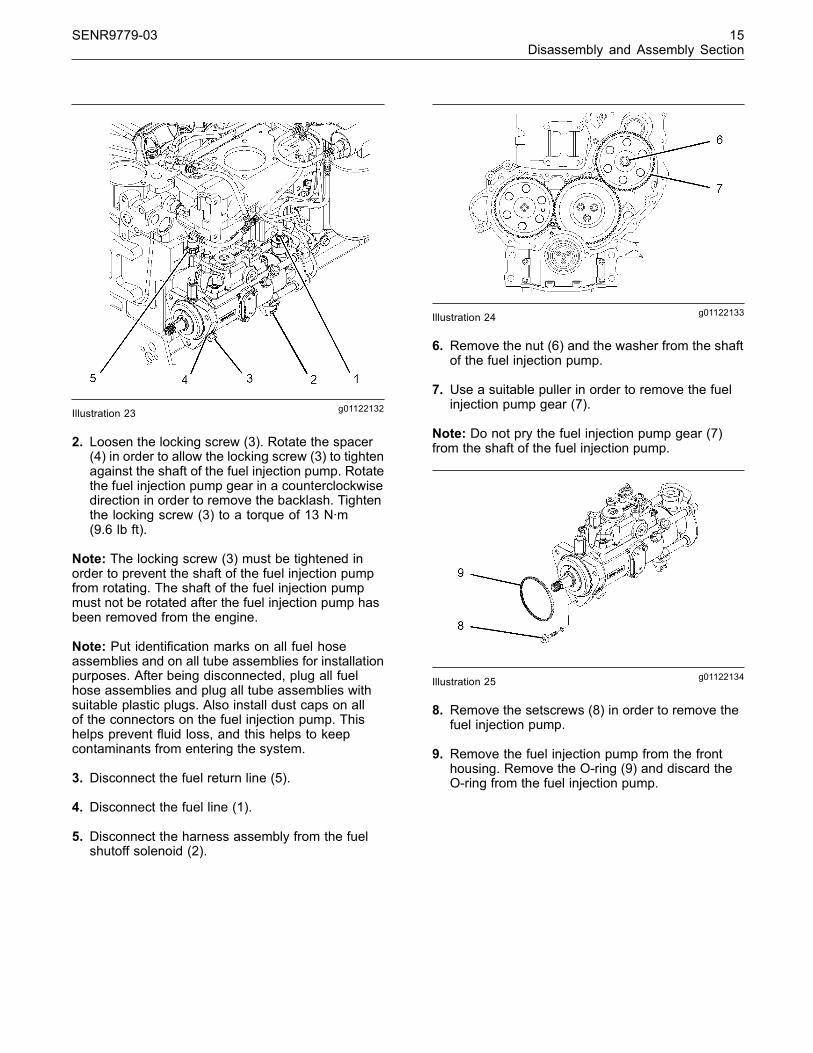
g01122132Illustration 23
2. Loosen the locking screw (3). Rotate the spacer(4) in order to allow the locking screw (3) to tightenagainst the shaft of the fuel injection pump. Rotatethe fuel injection pump gear in a counterclockwisedirection in order to remove the backlash. Tightenthe locking screw (3) to a torque of 13 N·m(9.6 lb ft).
Note: The locking screw (3) must be tightened inorder to prevent the shaft of the fuel injection pumpfrom rotating. The shaft of the fuel injection pumpmust not be rotated after the fuel injection pump hasbeen removed from the engine.
Note: Put identification marks on all fuel hoseassemblies and on all tube assemblies for installationpurposes. After being disconnected, plug all fuelhose assemblies and plug all tube assemblies withsuitable plastic plugs. Also install dust caps on allof the connectors on the fuel injection pump. Thishelps prevent fluid loss, and this helps to keepcontaminants from entering the system.
3. Disconnect the fuel return line (5).
4. Disconnect the fuel line (1).
5. Disconnect the harness assembly from the fuelshutoff solenoid (2).
g01122133Illustration 24
6. Remove the nut (6) and the washer from the shaftof the fuel injection pump.
7. Use a suitable puller in order to remove the fuelinjection pump gear (7).
Note: Do not pry the fuel injection pump gear (7)from the shaft of the fuel injection pump.
g01122134Illustration 25
8. Remove the setscrews (8) in order to remove thefuel injection pump.
9. Remove the fuel injection pump from the fronthousing. Remove the O-ring (9) and discard theO-ring from the fuel injection pump.
This document has been printed from SPI². Not for Resale

16 SENR9779-03Disassembly and Assembly Section
i01941022
Fuel Injection Pump - Remove(Bosch EPVE for the 1104engines only)
Removal ProcedureStart By:
a. Remove the fuel injection lines. Refer to thisDisassembly and Assembly Manual, “FuelInjection Lines - Remove and Install”.
b. Remove the crankshaft pulley. Refer to thisDisassembly and Assembly Manual, “CrankshaftPulley - Remove and Install”.
c. Remove the front cover. Refer to this Disassemblyand Assembly Manual, “Front Cover - Removeand Install”.
NOTICEKeep all parts clean from contaminants.
Contaminants may cause rapid wear and shortenedcomponent life.
1. Ensure that the No. 1 cylinder is at top deadcenter on the compression stroke. Refer to theTesting and Adjusting Manual, “Finding Top CenterPosition for No. 1 Piston”.
g00996409Illustration 26
Note: Put identification marks on all fuel hoseassemblies and on all tube assemblies for installationpurposes. After being disconnected, plug all fuelhose assemblies and plug all tube assemblies withsuitable plastic plugs. Also install dust caps on allof the connectors on the fuel injection pump. Thishelps prevent fluid loss, and this helps to keepcontaminants from entering the system.
2. Disconnect the tube assembly (1) from the fuelinjection pump. Disconnect the tube assembly (2)from the fuel injection pump.
3. Disconnect the wiring harness assembly fromthe cold start advance unit (3). Disconnect thewiring harness assembly from the engine shutoffsolenoid (4).
g00996410Illustration 27
This document has been printed from SPI². Not for Resale

SENR9779-03 17Disassembly and Assembly Section
4. Loosen the locking screw (6). Move the spacer (5)in order to allow the locking screw (6) to tightenagainst the shaft of the fuel injection pump. Rotatethe fuel injection pump gear in a counterclockwisedirection in order to remove the backlash. Tightenthe locking screw (6) to a torque of 31 N·m(23 lb ft).
Note: The locking screw (6) must be tightened inorder to prevent the shaft of the fuel injection pumpfrom rotating. The shaft of the fuel injection pumpmust not be rotated after the fuel injection pump hasbeen removed from the engine.
g01011474Illustration 28
5. Remove the nut (7) and the washer from the shaftof the fuel injection pump.
6. Use a suitable puller in order to remove the fuelinjection pump gear (8).
Note: Do not pry the fuel injection pump gear fromthe shaft of the fuel injection pump.
g00996474Illustration 29
7. Remove the nut (13). Remove the bolt (11).
8. If necessary, remove the setscrew and the bracket(10) from the cylinder block.
9. Remove the setscrews (12) in order to removethe fuel injection pump.
10.Remove the fuel injection pump from the fronthousing. Remove the O-ring (9) from the fuelinjection pump and discard the O-ring.
i02220108
Fuel Injection Pump - Remove(Delphi DPA)
Removal ProcedureStart By:
a. Remove the fuel injection lines. Refer to thisDisassembly and Assembly Manual, “FuelInjection Lines - Remove”.
b. Remove the crankshaft pulley. Refer to thisDisassembly and Assembly Manual, “CrankshaftPulley - Remove and Install”.
c. Remove the front cover. Refer to this Disassemblyand Assembly Manual, “Front Cover - Removeand Install”.
NOTICEKeep all parts clean from contaminants.
Contaminants may cause rapid wear and shortenedcomponent life.
1. Ensure that the No. 1 cylinder is at top deadcenter on the compression stroke. Refer to theTesting and Adjusting Manual, “Finding Top CenterPosition for No. 1 Piston”.
This document has been printed from SPI². Not for Resale

18 SENR9779-03Disassembly and Assembly Section
g01120559Illustration 30
Typical example
2. Loosen the locking screw (3). Rotate the spacer(4) in order to allow the locking screw (3) to tightenagainst the shaft of the fuel injection pump. Rotatethe fuel injection pump gear in a counterclockwisedirection in order to remove the backlash. Tightenthe locking screw (3) to a torque of 13 N·m(9.6 lb ft).
Note: The locking screw (3) must be tightened inorder to prevent the shaft of the fuel injection pumpfrom rotating. The shaft of the fuel injection pumpmust not be rotated after the fuel injection pump hasbeen removed from the engine.
Note: Put identification marks on all fuel hoseassemblies and on all tube assemblies for installationpurposes. After being disconnected, plug all fuelhose assemblies and plug all tube assemblies withsuitable plastic plugs. Also install dust caps on allof the connectors on the fuel injection pump. Thishelps prevent fluid loss, and this helps to keepcontaminants from entering the system.
3. Disconnect the fuel return line (5).
4. Disconnect the fuel line (2).
5. Disconnect the harness assembly from the fuelshutoff solenoid (1).
g01120567Illustration 31Typical example
6. Remove the nut (6) and the washer from the shaftof the fuel injection pump.
7. Use a suitable puller in order to remove the fuelinjection pump gear (7).
Note: Do not pry the fuel injection pump gear (7)from the shaft of the fuel injection pump.
g01120575Illustration 32Typical example
8. Remove the nut (8). Remove the bolt (10).
9. If necessary, remove the setscrew (11) and thebracket (9) from the cylinder block.
10.Remove the setscrews (12) in order to removethe fuel injection pump.
This document has been printed from SPI². Not for Resale

SENR9779-03 19Disassembly and Assembly Section
11.Remove the fuel injection pump from the fronthousing. Remove the O-ring (13) and discard theO-ring from the fuel injection pump.
i02216957
Fuel Injection Pump - Install(Delphi DP210)
Installation ProcedureNote: The installation procedure is identical for thefour cylinder and the three cylinder engines. Theillustrations show the four cylinder engine.
Note: The shaft of the fuel injection pump mustremain locked until the timing gear (9) has beeninstalled and tightened onto the shaft of the fuelinjection pump. The locking screw (5) must remainlocked until you are instructed to loosen the lockingscrew. The fuel injection pump must be returned toyour Perkins Dealer if the shaft of the fuel injectionpump was rotated accidentally.
NOTICEKeep all parts clean from contaminants.
Contaminants may cause rapid wear and shortenedcomponent life.
1. Ensure that the No. 1 cylinder is at top dead centeron the compression stroke. Refer to the Testingand Adjusting Manual, “Fuel Injection Timing -Check”.
g01062058Illustration 33
Typical example
Note: Do not lubricate the new O-ring (10). TheO-ring should be installed dry.
2. Install the new O-ring (10) onto the fuel injectionpump. Position the fuel injection pump onto thefront housing. Install the setscrews (13). Tightenthe setscrews (13) to a torque of 25 N·m (18 lb ft).
Note: The two steps that follow are only required ifthe bracket (11) is installed on the fuel injection pump.
3. Install the setscrew (15) and the bracket (11) ontothe cylinder block if the bracket was previouslyremoved. Ensure that the bracket (11) supportsthe fuel injection pump without applying any otherexternal force on the fuel injection pump. Tightenthe setscrew (15) to a torque of 44 N·m (32 lb ft).
4. Install the bolt (12) and the nut (14).
g01011369Illustration 34
Typical example
This document has been printed from SPI². Not for Resale

20 SENR9779-03Disassembly and Assembly Section
Note: Ensure that the mating surfaces of the fuelinjection pump gear and the shaft of the fuel injectionpump are clean. Lubricate the threads of the shaft forthe fuel injection pump. The nut (8) must turn freelyuntil contact is made with the fuel injection pumpgear.
5. Position the fuel injection pump gear (9) onto theshaft of the fuel injection pump. Install the washerand the nut (8). Rotate the fuel injection pumpgear (9) in a counterclockwise direction in orderto remove the backlash. Tighten the nut (8) to atorque of 24 N·m (17 lb ft).
g00956204Illustration 35
Typical example
6. Connect the harness assembly to the timingadvance solenoid (7).
7. Connect the harness assembly (2).
8. Remove all of the dust caps from the connectorson the fuel injection pump. Remove all of the plugsfrom the fuel hose assemblies and from the tubeassemblies.
9. Connect the fuel line (3), the fuel return line (1),and the tube assembly (4) to the fuel injectionpump.
10. Loosen the locking screw (5). Move the spacer(6) in order to prevent the locking screw (5) fromtightening against the shaft of the fuel injectionpump. Tighten the locking screw (5) to a torque of12 N·m (106 lb in).
Note: The spacer (6) must be correctly positionedand locking screw (5) must be tightened in order toprevent the locking screw from contacting the shaftof the fuel injection pump.
g01011369Illustration 36Typical example
11. Tighten the nut (8) to a torque of 88 N·m (65 lb ft).
End By:
a. Install the front cover. Refer to this Disassemblyand Assembly Manual, “Front Cover - Removeand Install”.
b. Install the crankshaft pulley. Refer to thisDisassembly and Assembly Manual, “CrankshaftPulley - Remove and Install”.
c. Install the fuel injection lines. Refer to thisDisassembly and Assembly Manual, “FuelInjection Lines - Install”.
i02075327
Fuel Injection Pump - Install(Delphi STP)
Installation ProcedureNote: The shaft of the fuel injection pump mustremain locked until the timing gear (8) has beeninstalled and tightened onto the shaft of the fuelinjection pump. The locking screw (1) must remainlocked until you are instructed to loosen the lockingscrew. The fuel injection pump must be returned toyour Perkins Dealer if the shaft of the fuel injectionpump was rotated accidentally.
NOTICEKeep all parts clean from contaminants.
Contaminants may cause rapid wear and shortenedcomponent life.
This document has been printed from SPI². Not for Resale
SENR9779-03 21Disassembly and Assembly Section
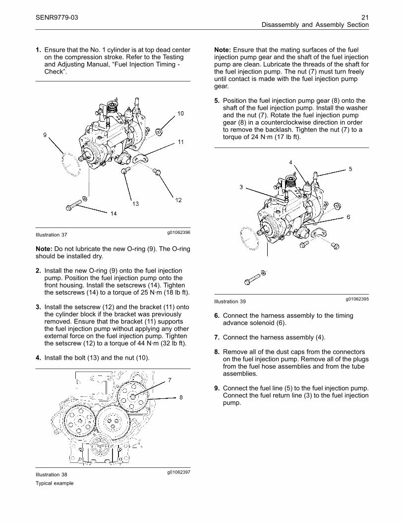
1. Ensure that the No. 1 cylinder is at top dead centeron the compression stroke. Refer to the Testingand Adjusting Manual, “Fuel Injection Timing -Check”.
g01062396Illustration 37
Note: Do not lubricate the new O-ring (9). The O-ringshould be installed dry.
2. Install the new O-ring (9) onto the fuel injectionpump. Position the fuel injection pump onto thefront housing. Install the setscrews (14). Tightenthe setscrews (14) to a torque of 25 N·m (18 lb ft).
3. Install the setscrew (12) and the bracket (11) ontothe cylinder block if the bracket was previouslyremoved. Ensure that the bracket (11) supportsthe fuel injection pump without applying any otherexternal force on the fuel injection pump. Tightenthe setscrew (12) to a torque of 44 N·m (32 lb ft).
4. Install the bolt (13) and the nut (10).
g01062397Illustration 38Typical example
Note: Ensure that the mating surfaces of the fuelinjection pump gear and the shaft of the fuel injectionpump are clean. Lubricate the threads of the shaft forthe fuel injection pump. The nut (7) must turn freelyuntil contact is made with the fuel injection pumpgear.
5. Position the fuel injection pump gear (8) onto theshaft of the fuel injection pump. Install the washerand the nut (7). Rotate the fuel injection pumpgear (8) in a counterclockwise direction in orderto remove the backlash. Tighten the nut (7) to atorque of 24 N·m (17 lb ft).
g01062395Illustration 39
6. Connect the harness assembly to the timingadvance solenoid (6).
7. Connect the harness assembly (4).
8. Remove all of the dust caps from the connectorson the fuel injection pump. Remove all of the plugsfrom the fuel hose assemblies and from the tubeassemblies.
9. Connect the fuel line (5) to the fuel injection pump.Connect the fuel return line (3) to the fuel injectionpump.
This document has been printed from SPI². Not for Resale
22 SENR9779-03Disassembly and Assembly Section
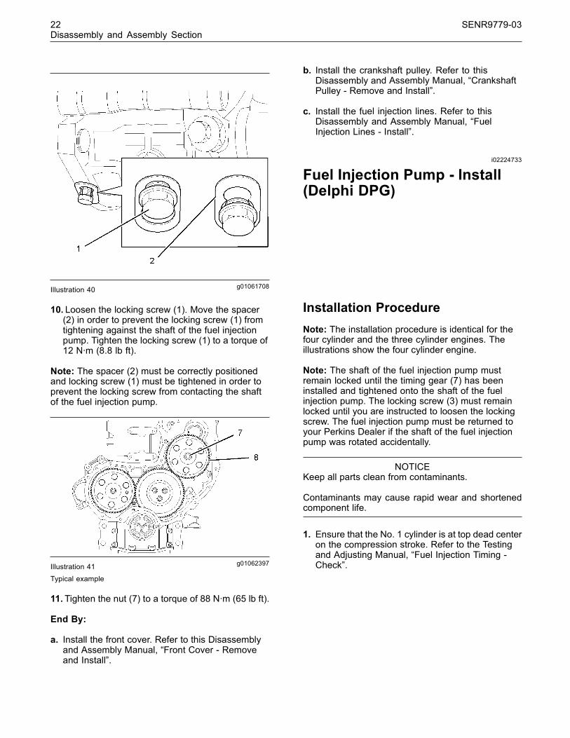
g01061708Illustration 40
10. Loosen the locking screw (1). Move the spacer(2) in order to prevent the locking screw (1) fromtightening against the shaft of the fuel injectionpump. Tighten the locking screw (1) to a torque of12 N·m (8.8 lb ft).
Note: The spacer (2) must be correctly positionedand locking screw (1) must be tightened in order toprevent the locking screw from contacting the shaftof the fuel injection pump.
g01062397Illustration 41Typical example
11.Tighten the nut (7) to a torque of 88 N·m (65 lb ft).
End By:
a. Install the front cover. Refer to this Disassemblyand Assembly Manual, “Front Cover - Removeand Install”.
b. Install the crankshaft pulley. Refer to thisDisassembly and Assembly Manual, “CrankshaftPulley - Remove and Install”.
c. Install the fuel injection lines. Refer to thisDisassembly and Assembly Manual, “FuelInjection Lines - Install”.
i02224733
Fuel Injection Pump - Install(Delphi DPG)
Installation ProcedureNote: The installation procedure is identical for thefour cylinder and the three cylinder engines. Theillustrations show the four cylinder engine.
Note: The shaft of the fuel injection pump mustremain locked until the timing gear (7) has beeninstalled and tightened onto the shaft of the fuelinjection pump. The locking screw (3) must remainlocked until you are instructed to loosen the lockingscrew. The fuel injection pump must be returned toyour Perkins Dealer if the shaft of the fuel injectionpump was rotated accidentally.
NOTICEKeep all parts clean from contaminants.
Contaminants may cause rapid wear and shortenedcomponent life.
1. Ensure that the No. 1 cylinder is at top dead centeron the compression stroke. Refer to the Testingand Adjusting Manual, “Fuel Injection Timing -Check”.
This document has been printed from SPI². Not for Resale

SENR9779-03 23Disassembly and Assembly Section
g01122134Illustration 42Typical example
Note: Do not lubricate the new O-ring (9). The O-ringshould be installed dry.
2. Install the new O-ring (9) onto the fuel injectionpump. Position the fuel injection pump onto thefront housing. Install the setscrews (8). Tightenthe setscrews (8) to a torque of 25 N·m (18 lb ft).
g01122133Illustration 43
Note: Ensure that the mating surfaces of the fuelinjection pump gear and the shaft of the fuel injectionpump are clean. Lubricate the threads of the shaft forthe fuel injection pump. The nut (6) must turn freelyuntil contact is made with the fuel injection pumpgear.
3. Position the fuel injection pump gear (7) onto theshaft of the fuel injection pump. Install the washerand the nut (6). Rotate the fuel injection pumpgear (7) in a counterclockwise direction in orderto remove the backlash. Tighten the nut (6) to atorque of 24 N·m (17 lb ft).
g01122132Illustration 44
4. Connect the harness assembly to the fuel shutoffsolenoid (2).
5. Remove all of the dust caps from the connectorson the fuel injection pump. Remove all of the plugsfrom the fuel hose assemblies and from the tubeassemblies.
6. Connect the fuel line (1) and the fuel return line (5)to the fuel injection pump.
7. Loosen the locking screw (3). Move the spacer(4) in order to prevent the locking screw (3) fromtightening against the shaft of the fuel injectionpump. Tighten the locking screw (3) to a torque of12 N·m (106 lb in).
Note: The spacer (4) must be correctly positionedand locking screw (3) must be tightened in order toprevent the locking screw from contacting the shaftof the fuel injection pump.
g01122133Illustration 45
8. Tighten the nut (6) to a torque of 88 N·m (65 lb ft).
This document has been printed from SPI². Not for Resale

24 SENR9779-03Disassembly and Assembly Section
End By:
a. Install the front cover. Refer to this Disassemblyand Assembly Manual, “Front Cover - Removeand Install”.
b. Install the crankshaft pulley. Refer to thisDisassembly and Assembly Manual, “CrankshaftPulley - Remove and Install”.
c. Install the fuel injection lines. Refer to thisDisassembly and Assembly Manual, “FuelInjection Lines - Install”.
i01943877
Fuel Injection Pump - Install(Bosch EPVE for the 1104engines only)
Installation ProcedureNote: The shaft of the fuel injection pump mustremain locked until the timing gear (8) has beeninstalled and tightened onto the shaft of the fuelinjection pump. The locking screw (6) must remainlocked until you are instructed to loosen the lockingscrew. The Bosch EPVE fuel injection pump can betimed to the engine by a technician. Refer to theTesting and Adjusting Manual, “Fuel Injection PumpTiming - Check and Fuel Injection Pump Timing -Adjust” if the shaft of the fuel injection pump wasrotated accidentally.
NOTICEKeep all parts clean from contaminants.
Contaminants may cause rapid wear and shortenedcomponent life.
1. Ensure that the No. 1 cylinder is at top dead centeron the compression stroke. Refer to the Testingand Adjusting Manual, “Fuel Injection Timing -Check”.
g00996474Illustration 46
2. Lightly lubricate a new O-ring (9) with Perkins1766-501 Silicone Fluid MS200/1000. Installthe new O-ring (9) onto the fuel injection pump.Position the fuel injection pump on the fronthousing. Install the setscrews (12). Tighten thesetscrews to a torque of 25 N·m (18 lb ft).
3. Install the setscrew and the bracket (10) ontothe cylinder block if the bracket was previouslyremoved. Ensure that the bracket (10) supportsthe fuel injection pump without applying any otherexternal force on the fuel injection pump. Tightenthe setscrew to a torque of 44 N·m (32 lb ft).
4. Install the bolt (11) and the nut (13).
Note: Ensure that the mating surfaces of the fuelinjection pump gear (8) and the shaft of the fuelinjection pump are clean. Lubricate the threads of theshaft for the fuel injection pump. The nut (7) mustturn freely until contact is made with the fuel injectionpump gear (8).
g01011474Illustration 47
This document has been printed from SPI². Not for Resale

SENR9779-03 25Disassembly and Assembly Section
5. Position the fuel injection pump gear (8) onto theshaft of the fuel injection pump. Install the washerand the nut (7). Rotate the fuel injection pumpgear (8) in a counterclockwise direction in orderto remove the backlash. Tighten the nut (7) to atorque of 24 N·m (17 lb ft).
g00996409Illustration 48
6. Connect the wiring harness assembly to theengine shutoff solenoid (4).
7. Connect the wiring harness assembly to the coldstart advance unit (3).
8. Remove all of the dust caps from the connectorson the fuel injection pump. Remove all of the plugsfrom the fuel hose assemblies and from the tubeassemblies.
9. Connect the tube assembly (2) to the fuel injectionpump. Connect the tube assembly (1) to the fuelinjection pump.
g00996410Illustration 49
10. Loosen the locking screw (6). Move spacer (5)in order to prevent the locking screw (6) fromtightening against the shaft of the fuel injectionpump. Tighten the locking screw (6) to a torque of12 N·m (106 lb in).
Note: The spacer (5) must be installed and thelocking screw (6) must be tightened in order toprevent the locking screw from contacting the shaftof the fuel injection pump.
g01011474Illustration 50
11. Tighten the nut (7) to a torque of 88 N·m (65 lb ft).
End By:
a. Install the front cover. Refer to this Disassemblyand Assembly Manual, “Front Cover - Removeand Install”.
b. Install the crankshaft pulley. Refer to thisDisassembly and Assembly Manual, “CrankshaftPulley - Remove and Install”.
c. Install the fuel injection lines. Refer to thisDisassembly and Assembly Manual, “FuelInjection Lines - Install”.
This document has been printed from SPI². Not for Resale
26 SENR9779-03Disassembly and Assembly Section
i02224693
Fuel Injection Pump - Install(Delphi DPA)
Installation ProcedureNote: The shaft of the fuel injection pump mustremain locked until the timing gear (7) has beeninstalled and tightened onto the shaft of the fuelinjection pump. The locking screw (3) must remainlocked until you are instructed to loosen the lockingscrew. The fuel injection pump must be returned toyour Perkins Dealer if the shaft of the fuel injectionpump was rotated accidentally.
NOTICEKeep all parts clean from contaminants.
Contaminants may cause rapid wear and shortenedcomponent life.
1. Ensure that the No. 1 cylinder is at top dead centeron the compression stroke. Refer to the Testingand Adjusting Manual, “Fuel Injection Timing -Check”.
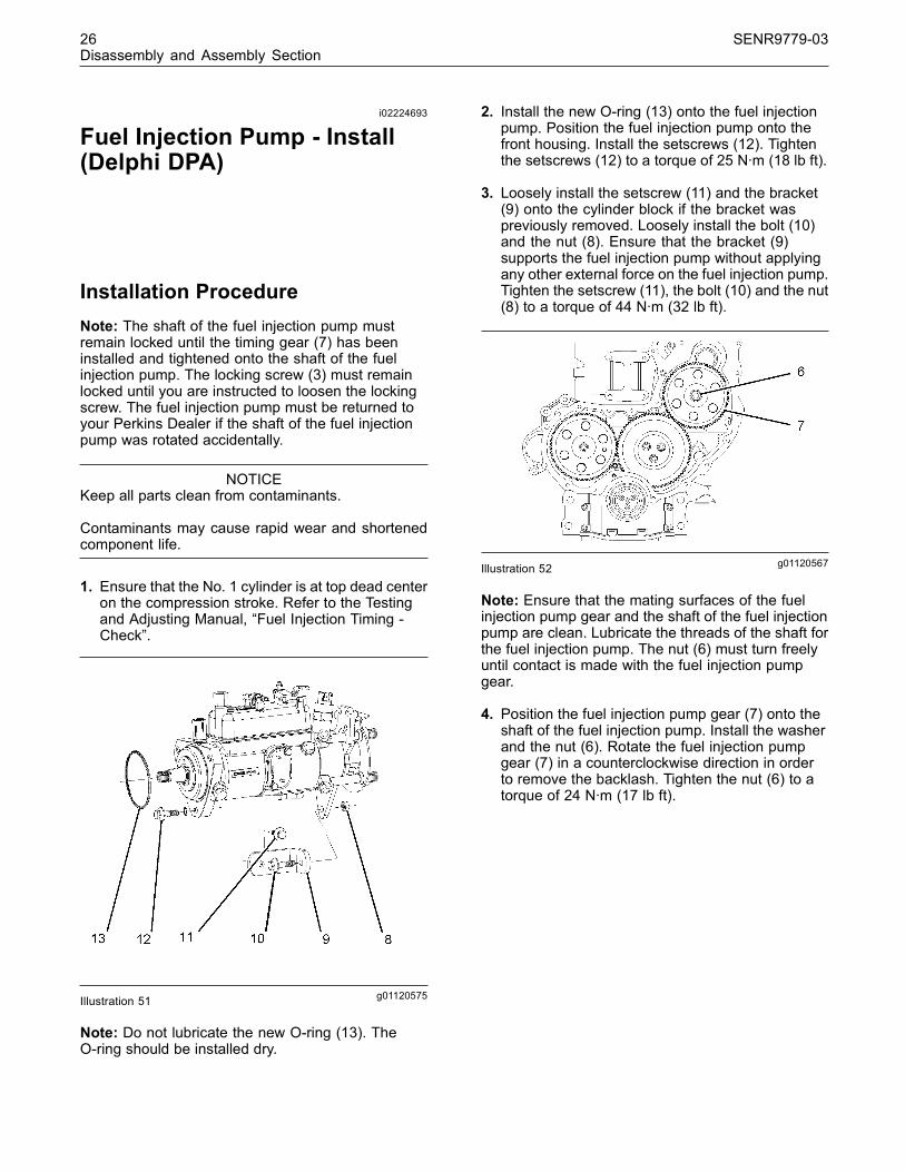
g01120575Illustration 51
Note: Do not lubricate the new O-ring (13). TheO-ring should be installed dry.
2. Install the new O-ring (13) onto the fuel injectionpump. Position the fuel injection pump onto thefront housing. Install the setscrews (12). Tightenthe setscrews (12) to a torque of 25 N·m (18 lb ft).
3. Loosely install the setscrew (11) and the bracket(9) onto the cylinder block if the bracket waspreviously removed. Loosely install the bolt (10)and the nut (8). Ensure that the bracket (9)supports the fuel injection pump without applyingany other external force on the fuel injection pump.Tighten the setscrew (11), the bolt (10) and the nut(8) to a torque of 44 N·m (32 lb ft).
g01120567Illustration 52
Note: Ensure that the mating surfaces of the fuelinjection pump gear and the shaft of the fuel injectionpump are clean. Lubricate the threads of the shaft forthe fuel injection pump. The nut (6) must turn freelyuntil contact is made with the fuel injection pumpgear.
4. Position the fuel injection pump gear (7) onto theshaft of the fuel injection pump. Install the washerand the nut (6). Rotate the fuel injection pumpgear (7) in a counterclockwise direction in orderto remove the backlash. Tighten the nut (6) to atorque of 24 N·m (17 lb ft).
This document has been printed from SPI². Not for Resale

SENR9779-03 27Disassembly and Assembly Section
g01120559Illustration 53
5. Connect the harness assembly to the fuel shutoffsolenoid (1).
6. Remove all of the dust caps from the connectorson the fuel injection pump. Remove all of the plugsfrom the fuel hose assemblies and from the tubeassemblies.
7. Connect the fuel line (2) and the fuel return line (5)to the fuel injection pump.
8. Loosen the locking screw (3). Move the spacer(4) in order to prevent the locking screw (3) fromtightening against the shaft of the fuel injectionpump. Tighten the locking screw (3) to a torque of12 N·m (106 lb in).
Note: The spacer (4) must be correctly positionedand locking screw (3) must be tightened in order toprevent the locking screw from contacting the shaftof the fuel injection pump.
g01120567Illustration 54
9. Tighten the nut (6) to a torque of 88 N·m (65 lb ft).
End By:
a. Install the front cover. Refer to this Disassemblyand Assembly Manual, “Front Cover - Removeand Install”.
b. Install the crankshaft pulley. Refer to thisDisassembly and Assembly Manual, “CrankshaftPulley - Remove and Install”.
c. Install the fuel injection lines. Refer to thisDisassembly and Assembly Manual, “FuelInjection Lines - Install”.
i01938589
Fuel Injector - Remove
Removal ProcedureStart By:
a. Remove the cover for the fuel injectors. Refer tothis Disassembly and Assembly Manual, “FuelInjector Cover - Remove and Install”.
b. Remove the fuel injection lines. Refer to thisDisassembly and Assembly, “Fuel Injection Lines- Remove”.
NOTICEKeep all parts clean from contaminants.
Contaminants may cause rapid wear and shortenedcomponent life.
NOTICECare must be taken to ensure that fluids are containedduring performance of inspection, maintenance, test-ing, adjusting and repair of the product. Be prepared tocollect the fluid with suitable containers before open-ing any compartment or disassembling any compo-nent containing fluids.
Dispose of all fluids according to local regulations andmandates.
1. Disconnect the tube assemblies from the fuel filterbase for the fuel inlet and the fuel outlet.
This document has been printed from SPI². Not for Resale

28 SENR9779-03Disassembly and Assembly Section
g00975056Illustration 55
2. Remove the fuel hose (2) from the fuel injector (1).
3. Remove the setscrew (3). Remove the clamp (4)from the fuel injector (1).
4. Remove the fuel injector (1) from the cylinderhead. Remove the O-ring seal (5) from the fuelinjector (1) and discard the O-ring.
5. Remove the seat washer (6) from the cylinderhead and discard the seat washer.
Note: If the original seat washer is not removed, theprojection of the fuel injector will be incorrect when anew seat washer is installed.
i02241916
Fuel Injector - Install
Installation Procedure
NOTICEKeep all parts clean from contaminants.
Contaminants may cause rapid wear and shortenedcomponent life.
g01129982Illustration 56
1. Lubricate the seat washer (6) with clean engine oil.Install a new seat washer (6) in the cylinder head.
Note: If the original seat washer (6) is reused, theprojection of the fuel injector (1) will be incorrect.
2. Install a new O-ring seal (5) on fuel injector (1).Install the fuel injector (1) in the cylinder head.
Note: Alignment Pin (7) must be located oppositeclamp (4).
3. Position clamp (4) on the fuel injector (1). Installsetscrew (3). Tighten the setscrew to a torque of27 N·m (20 lb ft).
4. Install hose (2) to the fuel injector (1).
End By:
a. Install the fuel injection lines. Refer to thisDisassembly and Assembly, “Fuel Injection Lines- Install”.
b. Install the cover for the fuel injectors. Refer to thisDisassembly and Assembly Manual, “Fuel InjectorCover - Remove and Install”.
This document has been printed from SPI². Not for Resale

SENR9779-03 29Disassembly and Assembly Section
i01944022
Turbocharger - Remove
Removal Procedure
NOTICEKeep all parts clean from contaminants.
Contaminants may cause rapid wear and shortenedcomponent life.
NOTICECare must be taken to ensure that fluids are containedduring performance of inspection, maintenance, test-ing, adjusting and repair of the product. Be prepared tocollect the fluid with suitable containers before open-ing any compartment or disassembling any compo-nent containing fluids.
Dispose of all fluids according to local regulations andmandates.
Note: The removal procedure is identical for thethree cylinder and the four cylinder engines.
1. Thoroughly clean the outer surfaces of theturbocharger (1).
2. Loosen the hose clamps and remove the air inlethose at the turbocharger compressor housing.
Note: Exhaust elbows are only an option for the fourcylinder engines.
3. Remove the exhaust pipe from the turbochargeroutlet or remove the exhaust pipe from the exhaustelbow. Refer to the OEM provided informationfor the correct procedure in order to remove theexhaust pipe.
g01038600Illustration 57Typical example
4. If an exhaust elbow is installed, remove theexhaust elbow. Refer to this Disassembly andAssembly Manual, “Exhaust Elbow - Remove andInstall”.
5. Remove the nuts (2) and remove the exhaustadapter (3) from the turbocharger (1).
6. Place a suitable container below the turbocharger(1) in order to collect any spillage of oil.
g01038396Illustration 58Typical example
This document has been printed from SPI². Not for Resale

30 SENR9779-03Disassembly and Assembly Section
7. Remove the banjo bolts (5). Remove the oilsupply tube assembly (6) and the washers (7)from the turbocharger (1). Discard the washers(7). If necessary, remove the oil supply tubeassembly (6) from the cylinder block and discardthe washers.
8. Remove the setscrews (8). Remove the oil draintube assembly (9) from the turbocharger (1).Remove the joint (10) and discard the joint. Ifnecessary, remove the setscrews (11) and removethe oil drain tube assembly (9) from the cylinderblock. Discard the joint.
9. If necessary, remove the studs (12) from theturbocharger housing.
Note: Do not use the actuator rod of the wastegate(16) to lift the turbocharger (1).
10.Remove the nuts (13). Remove the turbocharger(1). Remove the gasket (14). Discard the gasket(14). If necessary, remove the studs (15) from theexhaust manifold.
11. Install suitable plastic plugs into the oil supplyand into the oil drain ports of the turbocharger (1).Install suitable plastic covers to the inlet and tothe outlet of the turbocharger (1). Install suitableplastic plugs to the oil supply tube assembly (6)and to the oil drain tube assembly (9). Installsuitable plastic covers to the manifold ports.
i01944024
Turbocharger - Install
Installation Procedure
NOTICEKeep all parts clean from contaminants.
Contaminants may cause rapid wear and shortenedcomponent life.
Note: The installation procedure is identical for thethree cylinder and the four cylinder engines.
1. Remove all of the plastic plugs from all of the portsof the turbocharger (1). Clean the mating surfacesof the exhaust manifold and the turbocharger.Clean the mating surfaces of the turbochargerto the oil supply tube assembly (6) and theturbocharger to the oil drain tube assembly (9).
2. Ensure that all of the turbocharger inlet and outletports are clean and free from restrictions. Theturbocharger shaft must rotate freely.
g01038396Illustration 59Typical example
3. If the studs (15) were previously removed, installthe studs into the exhaust manifold. Install a newgasket (14) over the studs (15).
Note: Do not use any sealant on the gasket (14).
Note: Do not use the actuator rod of the wastegate(16) to lift the turbocharger (1).
4. Position the turbocharger (1) onto the exhaustmanifold.
5. Install the nuts (13). Tighten the nuts (13) to atorque of 47 N·m (35 lb ft).
6. Lubricate the bearing housing of the turbocharger(1) with clean engine oil.
7. Inspect all of the oil hose assemblies (6 and 9). Ifnecessary, replace the hose assemblies (6 and 9).
This document has been printed from SPI². Not for Resale

SENR9779-03 31Disassembly and Assembly Section
Note: The top flange of the oil drain tube assembly(9) is secured to the turbocharger (1) with 6 mmsetscrews (8). The bottom flange of the oil drain tubeassembly (9) is secured to the cylinder block with 8mm setscrews (11).
8. Position a new joint (10) and the oil drain tubeassembly (9) onto the bottom of the turbocharger(1). Install the 6 mm setscrews (8). Tighten the 6mm setscrews (8) to a torque of 9 N·m (80 lb in).
9. Position a new joint and the oil drain tubeassembly (9) onto the cylinder block. Tighten the 8mm setscrews (11) to a torque of 22 N·m (16 lb ft).
10.Position the new washers (7) and the oil supplytube assembly (6) onto the turbocharger (1).Install the banjo bolt (5). Tighten the banjo bolt (5)to a torque of 22 N·m (16 lb ft).
Note: Ensure that the oil supply tube assembly (6)does not come into contact with any other componentwhen the assembly is installed onto the engine.
11. Install the new washers and the oil supply tubeassembly (6) to the cylinder block. Tighten thebanjo bolt to a torque of 22 N·m (16 lb ft).
12. If the studs (12) were previously removed, installthe studs into the turbocharger housing.
g01038406Illustration 60Typical example
13.Position the exhaust adapter (3) onto the studs(12). Install the nuts (2). Do not tighten the nuts(2) at this time.
Note: Exhaust elbows are only an option for the fourcylinder engines.
14. If equipped, install the exhaust elbow onto theexhaust adapter (3). Refer to this Disassemblyand Assembly Manual, “Exhaust Elbow - Removeand Install”.
g01038456Illustration 61
15. Tighten the three nuts finger tight in the sequence(17), (18), and (19). Tighten the nuts (17), (18),and (19) in the same sequence to a torque of25 N·m (18 lb ft).
16.Ensure that there is no restriction in the inlet hose.Position the air inlet hose on the turbochargercompressor housing. Install the hose clamps.Tighten the hose clamps to a torque of 5 N·m(44 lb in).
Note: The air inlet hose has a reflective heat shieldthat partially covers the hose. The reflective heatshield must be installed toward the engine. Thereflective heat shield must be kept clean and freefrom dust, oil or paint.
Note: Apply a solution of water and 5% soap to theinlet of the turbocharger in order to install a new airinlet hose. Do not use oil or grease in order to installthe air inlet hose.
17.Position the exhaust pipe onto the exhaust elbowor onto the turbocharger outlet (3). Refer to theOEM information for the correct procedure inorder to install the exhaust pipe.
i01946913
Exhaust Manifold - Removeand Install
Removal Procedure for the ThreeCylinder EngineStart By:
a. Remove the turbocharger, if equipped. Referto this Disassembly and Assembly Manual,“Turbocharger - Remove”.
This document has been printed from SPI². Not for Resale
32 SENR9779-03Disassembly and Assembly Section
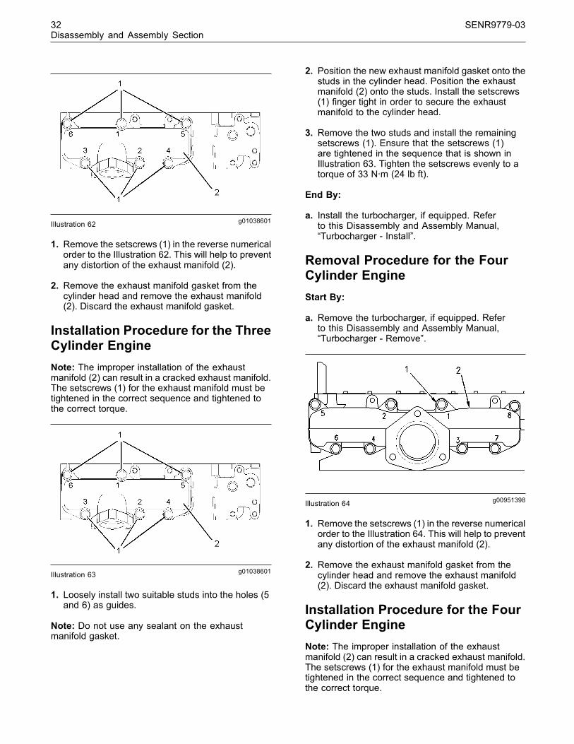
g01038601Illustration 62
1. Remove the setscrews (1) in the reverse numericalorder to the Illustration 62. This will help to preventany distortion of the exhaust manifold (2).
2. Remove the exhaust manifold gasket from thecylinder head and remove the exhaust manifold(2). Discard the exhaust manifold gasket.
Installation Procedure for the ThreeCylinder EngineNote: The improper installation of the exhaustmanifold (2) can result in a cracked exhaust manifold.The setscrews (1) for the exhaust manifold must betightened in the correct sequence and tightened tothe correct torque.
g01038601Illustration 63
1. Loosely install two suitable studs into the holes (5and 6) as guides.
Note: Do not use any sealant on the exhaustmanifold gasket.
2. Position the new exhaust manifold gasket onto thestuds in the cylinder head. Position the exhaustmanifold (2) onto the studs. Install the setscrews(1) finger tight in order to secure the exhaustmanifold to the cylinder head.
3. Remove the two studs and install the remainingsetscrews (1). Ensure that the setscrews (1)are tightened in the sequence that is shown inIllustration 63. Tighten the setscrews evenly to atorque of 33 N·m (24 lb ft).
End By:
a. Install the turbocharger, if equipped. Referto this Disassembly and Assembly Manual,“Turbocharger - Install”.
Removal Procedure for the FourCylinder EngineStart By:
a. Remove the turbocharger, if equipped. Referto this Disassembly and Assembly Manual,“Turbocharger - Remove”.
g00951398Illustration 64
1. Remove the setscrews (1) in the reverse numericalorder to the Illustration 64. This will help to preventany distortion of the exhaust manifold (2).
2. Remove the exhaust manifold gasket from thecylinder head and remove the exhaust manifold(2). Discard the exhaust manifold gasket.
Installation Procedure for the FourCylinder EngineNote: The improper installation of the exhaustmanifold (2) can result in a cracked exhaust manifold.The setscrews (1) for the exhaust manifold must betightened in the correct sequence and tightened tothe correct torque.
This document has been printed from SPI². Not for Resale

SENR9779-03 33Disassembly and Assembly Section
g00951398Illustration 65
1. Loosely install two suitable studs into the holes (5and 8) as guides.
Note: Do not use any sealant on the exhaustmanifold gasket.
2. Position the new exhaust manifold gasket onto thestuds in the cylinder head. Position the exhaustmanifold (2) onto the studs. Install the setscrews(1) finger tight in order to secure the exhaustmanifold to the cylinder head.
3. Remove the two studs and install the remainingsetscrews (1). Ensure that the setscrews (1)are tightened in the sequence that is shown inIllustration 65. Tighten the setscrews evenly to atorque of 33 N·m (24 lb ft).
End By:
a. Install the turbocharger, if equipped. Referto this Disassembly and Assembly Manual,“Turbocharger - Install”.
i02216959
Exhaust Elbow - Remove andInstall(If Equipped)
Removal ProcedureStart By:
a. Remove the exhaust pipe. Refer to the OEMinformation for the correct procedure in order toremove the exhaust pipe.
g01135897Illustration 66Typical example
1. Remove the setscrews (3) from the exhaust elbow(4). Remove the setscrews (1) and remove thebracket (2) from the cylinder block. Remove theexhaust elbow (4) from the exhaust adapter (5).
This document has been printed from SPI². Not for Resale

34 SENR9779-03Disassembly and Assembly Section
Installation Procedure
g01135897Illustration 67Typical example
1. Thoroughly clean the exhaust elbow (4) and theexhaust adapter (5).
2. Install the exhaust elbow (4) onto the exhaustadapter (5). Position the bracket (2) onto thecylinder block and install the setscrews (1).Tighten the setscrews (1) finger tight. Align theexhaust elbow with the bracket (2). Install thesetscrews (3) in order to secure the exhaustelbow (4) to the bracket (2). Tighten the setscrews(1) and tighten the setscrews (3) to a torque of44 N·m (33 lb ft).
.
End By:
a. Install the exhaust pipe. Refer to the OEMinformation for the correct procedure in order toinstall the exhaust pipe.
i01947651
Inlet and Exhaust ValveSprings - Remove and Install
Removal ProcedureTable 1
Required Tools
Part Number Part Description Qty
21825666 Valve Spring Compressor 1
27610235 Setscrew Adapter 1
Start By:
a. Remove the rocker shaft assembly. Refer to thisDisassembly and Assembly Manual, “RockerShaft and Pushrod - Remove”.
NOTICEKeep all parts clean from contaminants.
Contaminants may cause rapid wear and shortenedcomponent life.
Note: The following procedure should be adopted inorder to remove the valve springs when the cylinderhead is still installed onto the cylinder block. Refer tothis Disassembly and Assembly Manual, “Inlet andExhaust Valves - Remove and Install” for the correctprocedure that should be used to remove the valvesprings from a cylinder head that has been removedfrom the cylinder block.
Note: Ensure that the appropriate piston is at topdead center before the valve spring is removed.Failure to ensure that the piston is at top dead centermay allow the valve to drop into the cylinder block.
1. Use the following procedure in order to find thetop dead center position for the appropriate piston.
Personal injury can result from being struck byparts propelled by a released spring force.
Make sure to wear all necessary protective equip-ment.
Follow the recommended procedure and use allrecommended tooling to release the spring force.
This document has been printed from SPI². Not for Resale
SENR9779-03 35Disassembly and Assembly Section
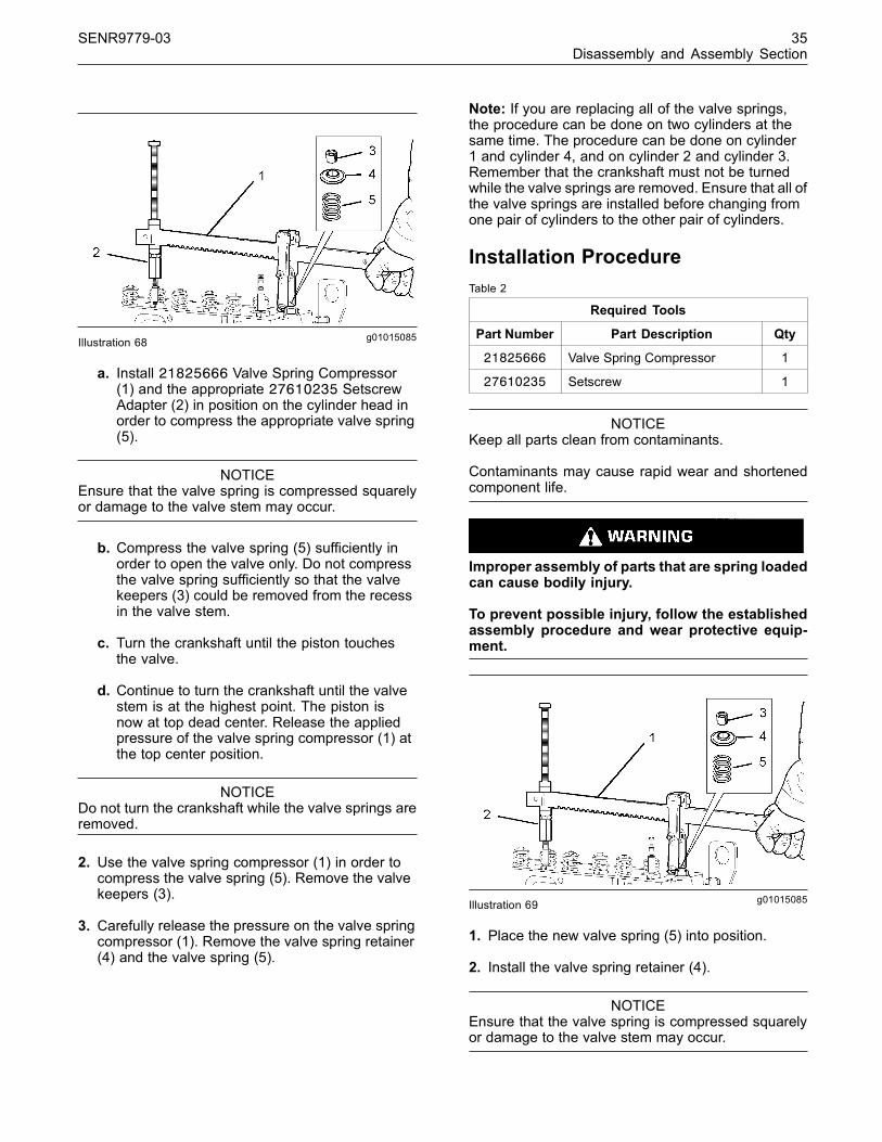
g01015085Illustration 68
a. Install 21825666 Valve Spring Compressor(1) and the appropriate 27610235 SetscrewAdapter (2) in position on the cylinder head inorder to compress the appropriate valve spring(5).
NOTICEEnsure that the valve spring is compressed squarelyor damage to the valve stem may occur.
b. Compress the valve spring (5) sufficiently inorder to open the valve only. Do not compressthe valve spring sufficiently so that the valvekeepers (3) could be removed from the recessin the valve stem.
c. Turn the crankshaft until the piston touchesthe valve.
d. Continue to turn the crankshaft until the valvestem is at the highest point. The piston isnow at top dead center. Release the appliedpressure of the valve spring compressor (1) atthe top center position.
NOTICEDo not turn the crankshaft while the valve springs areremoved.
2. Use the valve spring compressor (1) in order tocompress the valve spring (5). Remove the valvekeepers (3).
3. Carefully release the pressure on the valve springcompressor (1). Remove the valve spring retainer(4) and the valve spring (5).
Note: If you are replacing all of the valve springs,the procedure can be done on two cylinders at thesame time. The procedure can be done on cylinder1 and cylinder 4, and on cylinder 2 and cylinder 3.Remember that the crankshaft must not be turnedwhile the valve springs are removed. Ensure that all ofthe valve springs are installed before changing fromone pair of cylinders to the other pair of cylinders.
Installation ProcedureTable 2
Required Tools
Part Number Part Description Qty
21825666 Valve Spring Compressor 1
27610235 Setscrew 1
NOTICEKeep all parts clean from contaminants.
Contaminants may cause rapid wear and shortenedcomponent life.
Improper assembly of parts that are spring loadedcan cause bodily injury.
To prevent possible injury, follow the establishedassembly procedure and wear protective equip-ment.
g01015085Illustration 69
1. Place the new valve spring (5) into position.
2. Install the valve spring retainer (4).
NOTICEEnsure that the valve spring is compressed squarelyor damage to the valve stem may occur.
This document has been printed from SPI². Not for Resale

36 SENR9779-03Disassembly and Assembly Section
3. Install the valve spring compressor (1) in positionon the cylinder head in order to compress theappropriate valve spring (5). Compress the valvespring (5).
4. Install the valve keepers (3).
NOTICEDo not turn the crankshaft while the valve springs areremoved.
5. Carefully release the pressure on the valvespring compressor (1). Remove the valve springcompressor (1). Ensure that all of the valves aresecured in place by a valve spring and valvekeepers. Rotate the crankshaft through about45 degrees in order to clear the piston from thevalve. Lightly strike the top of the valve with a softhammer in order to ensure that the valve keepers(3) are properly installed.
Note: If you are replacing all of the valve springs theprocedure can be done on two cylinders at the sametime. The procedure can be done on cylinder 1 andcylinder 4, and on cylinder 2 and cylinder 3.
End By:
a. Install the rocker shaft assembly. Refer to thisDisassembly and Assembly, “Rocker Shaft andPushrod - Install”.
i01947652
Inlet and Exhaust Valves -Remove and Install
Removal ProcedureTable 3
Required Tools
Part Number Part Description Qty
21825496 Valve Depth Gauge 1
21825666 Valve Spring Compressor 1
27610235 Setscrew Adapter 1
Start By:
a. Remove the cylinder head assembly. Refer to thisDisassembly and Assembly Manual, “CylinderHead - Remove”.
Note: Ensure that the machined face of the cylinderhead is kept on a clean, soft surface in order toprevent damage to the machined surface.
NOTICEKeep all parts clean from contaminants.
Contaminants may cause rapid wear and shortenedcomponent life.
Note: The removal procedure is identical for thethree cylinder and the four cylinder engines. Theillustrations show the four cylinder engine.
g01015306Illustration 70Typical example
1. Use a dial indicator to check the depth of thevalves below the face of the cylinder head beforethe valve springs are removed. Refer to theillustration 70 and refer to Specifications, “CylinderHead Valves” for the correct dimensions.
Note: The head of the inlet valve has a largerdiameter than the head of the exhaust valve.
2. Place a numerical index mark on the heads ofthe inlet valves and on the exhaust valves sothat each valve can be installed in the correctsequence during installation.
This document has been printed from SPI². Not for Resale

SENR9779-03 37Disassembly and Assembly Section
g01015303Illustration 71Typical example
g01015305Illustration 72Typical example
3. Install 21825666 Valve Spring Compressor (1)and the appropriate 27610235 Setscrew Adapter(2) in position on the cylinder head in order tocompress the appropriate valve spring (5).
Personal injury can result from being struck byparts propelled by a released spring force.
Make sure to wear all necessary protective equip-ment.
Follow the recommended procedure and use allrecommended tooling to release the spring force.
NOTICEEnsure that the valve spring is compressed squarelyor damage to the valve stem may occur.
4. Compress the valve spring (5).
5. Remove the valve keepers (3).
6. Carefully release the pressure on the valvespring compressor (1). Remove the valve springcompressor (1) and the setscrew adapter (2) fromthe cylinder head.
7. Remove the valve spring retainer (4).
8. Remove the valve spring (5).
9. Remove the valve stem seal (6). Discard the valvestem seal (6).
10.Remove the appropriate valve (7 or 8).
11.Repeat Step 3 to Step 10 for each inlet valve (7)and for each exhaust valve (8).
Installation ProcedureTable 4
Required Tools
Part Number Part Description Qty
21825666 Valve Spring Compressor 1
27610235 Setscrew Adapter 1
21825496 Valve Depth Gauge 1
NOTICEKeep all parts clean from contaminants.
Contaminants may cause rapid wear and shortenedcomponent life.
Note: The installation procedure is identical for thethree cylinder and the four cylinder engines. Theillustrations show the four cylinder engine.
This document has been printed from SPI². Not for Resale

38 SENR9779-03Disassembly and Assembly Section
g01015305Illustration 73
Typical example
1. Carefully clean the bottom face of the cylinderhead. Ensure that there is no debris in the inletand exhaust ports. Also ensure that there is nodebris in the coolant passages and in lubricationpassages. Inspect the cylinder head. Refer to theTesting and Adjusting Manual, “Cylinder HeadInspect” for further information.
2. Inspect all of the valve seats for wear and fordamage. Refer to the Specifications Manual,“Cylinder Head Valves” for further information.Also refer to this Disassembly and AssemblyManual, “Inlet and Exhaust Valve Seat Inserts- Remove and Install” and refer to Testing andAdjusting Manual, “Valve Depth - Inspect ” forfurther information. Replace any worn parts.
3. Inspect all of the valve guides for wear and fordamage. Refer to the Specifications Manual,“Cylinder Head Valves” for further information.Also refer to this Disassembly and AssemblyManual, “Inlet and Exhaust Valve Guides -Remove and Install” and refer to Testing andAdjusting Manual, “Valve Guide - Inspect” forfurther information. Replace any worn parts.
4. Inspect the valves if the valves are notreplacement parts. Refer to the SpecificationsManual, “Cylinder Head Valves” for furtherinformation.
5. Lubricate the stems of all of the inlet valves (7)and lubricate the stems of all of the exhaust valves(8) with clean engine oil. Install the inlet valves(7) and the exhaust valves (8) in the appropriatepositions.
6. Carefully turn over the cylinder head and ensurethat all of the valves remain in place. Place themachined surface of the cylinder head onto aclean, soft surface.
Note: The valve guides must be clean and dry beforeinstalling the valve stem seals (6).
7. Install a new valve stem seal (6) onto each of thevalve guides.
8. Inspect the valve springs (5) for wear and for thecorrect installed length. Refer to the SpecificationsManual, “Cylinder Head Valves ” for furtherinformation on the correct installed length of thevalve springs (5). Replace any worn parts.
9. Install the valve springs (5) onto the cylinder head.
10. Install the valve spring retainers (4).
g01015303Illustration 74Typical example
Personal injury can result from being struck byparts propelled by a released spring force.
Make sure to wear all necessary protective equip-ment.
Follow the recommended procedure and use allrecommended tooling to release the spring force.
NOTICEEnsure that the valve spring is compressed squarelyor damage to the valve stem may occur.
11. Install 21825666 Valve Spring Compressor (1)and the appropriate 27610235 Setscrew Adapter(2) in position on the cylinder head in order tocompress the appropriate valve spring (5).
12. Install the valve keepers (3).
This document has been printed from SPI². Not for Resale

SENR9779-03 39Disassembly and Assembly Section
13.Carefully release the pressure on the valvespring compressor (1). Remove the valve springcompressor (1) and the setscrew adapter (2) fromthe cylinder head. Gently strike the top of theappropriate valves with a soft hammer in orderto ensure that the valve keepers (3) are properlyinstalled.
14.Repeat Step 11 to Step 13 for all of the valves(7 and 8).
15. Turn over the cylinder head. Use a dial indicatorto check the depth of the new valves below theface of the cylinder head. Refer to Illustration 70and refer to the Specifications Manual, “CylinderHead Valves” for more information on the inletvalves and the exhaust valves. If the depth ofthe new valves is below the correct depth, thevalve seat inserts must be replaced. Refer to thisDisassembly and Assembly Manual, “Inlet andExhaust Valve Seat Inserts - Remove and Install”.
End By:
a. Install the cylinder head assembly. Refer to thisDisassembly and Assembly Manual, “CylinderHead - Install”.
i01947653
Inlet and Exhaust Valve Guides- Remove and Install
Removal ProcedureTable 5
Required Tools
Part Number Part Description Qty
21825478 Valve Guide Remover/Replacer 1
21825479 Valve Guide Adapter 1
Start By:
a. Remove the cylinder head. Refer to thisDisassembly and Assembly Manual, “CylinderHead - Remove”.
b. Remove the inlet valves and the exhaust valves.Refer to this Disassembly and Assembly Manual,“Inlet and Exhaust Valves - Remove and Install”.
NOTICEKeep all parts clean from contaminants.
Contaminants may cause rapid wear and shortenedcomponent life.
g01016267Illustration 75
1. Install the 21825479 Valve Guide Adapter (1) intothe 21825478 Valve Guide Remover/Replacer(2).
2. Place the spacer (3) into the appropriate valveseat.
3. Pass the adapter (1) through the valve guide (4)and install the valve guide remover/replacer (2)onto the spacer (3).
4. Install the attachment (5) in order to secure theadapter (1) to the valve guide (4).
5. Hold the top handle (6) and turn the bottom handle(7) counterclockwise in order to push the valveguide (4) from the cylinder head.
6. Repeat Step 2 to Step 5 in order to extract eachappropriate valve guide (4).
7. Discard all of the valve guides (4) that wereremoved from the cylinder head.
Note: When new valve guides are installed, newvalves and new valve seat inserts must be installed.
This document has been printed from SPI². Not for Resale

40 SENR9779-03Disassembly and Assembly Section
8. Remove the valve seat inserts. Refer to thisDisassembly and Assembly Manual, “Inlet andExhaust Valve Seat Inserts - Remove and Install”.
Installation ProcedureTable 6
Required Tools
Part Number Part Description Qty
21825478 Valve Guide Remover/Replacer 1
27610234 Valve Guide Adapter 1
NOTICEKeep all parts clean from contaminants.
Contaminants may cause rapid wear and shortenedcomponent life.
g01016462Illustration 76
1. Clean the parent bores in the cylinder head for allof the appropriate valve guides (4).
2. Install the 27610234 Valve Guide Adaptor (8) intothe 21825478 Valve Guide Remover/Replacer(2).
3. Install the spacer (3) into the appropriate valveseat.
4. Lubricate the outer surface of a new valve guide(4) with clean engine lubricating oil. Pass theadapter (8) through the parent bore for thevalve guide (4) and position the valve guideremover/replacer (2) onto the spacer (3).
5. Install the adapter (10) beneath the valve guide(4). Install the attachment (5) in order to securethe adapter (10) to the valve guide (4).
Note: The valve guide (4) should protrude above thecylinder head. Ensure that the protrusion (9) is withinlimits.
6. Hold the top handle (6) and turn the bottomhandle (7) clockwise in order to pull the valveguide (4) into the cylinder head. Continue to pullthe valve guide (4) into the cylinder head until thecorrect amount of protrusion (9) is reached. Thevalve guides should protrude 12.35 to 12.65 mm(0.4862 to 0.4980 inch) above the valve springrecess.
7. Repeat the Step 3 to Step 6 in order to install eachappropriate valve guide.
Note: The parent bores of the valve guides mustbe reamed to the correct size after the valve guideshave been installed into the cylinder head. Also, thevalve inserts must be inserted and the seat facesmust be cut to the correct angle. The same tool isused to finish both components.
8. Install the valve seat inserts and finish bothcomponents. Refer to this Disassembly andAssembly Manual, “Inlet and Exhaust Valve SeatInserts - Remove and Install”.
End By:
a. Install the inlet valves and the exhaust valves.Refer to this Disassembly and Assembly Manual,“Inlet and Exhaust Valves - Remove and Install”.
This document has been printed from SPI². Not for Resale
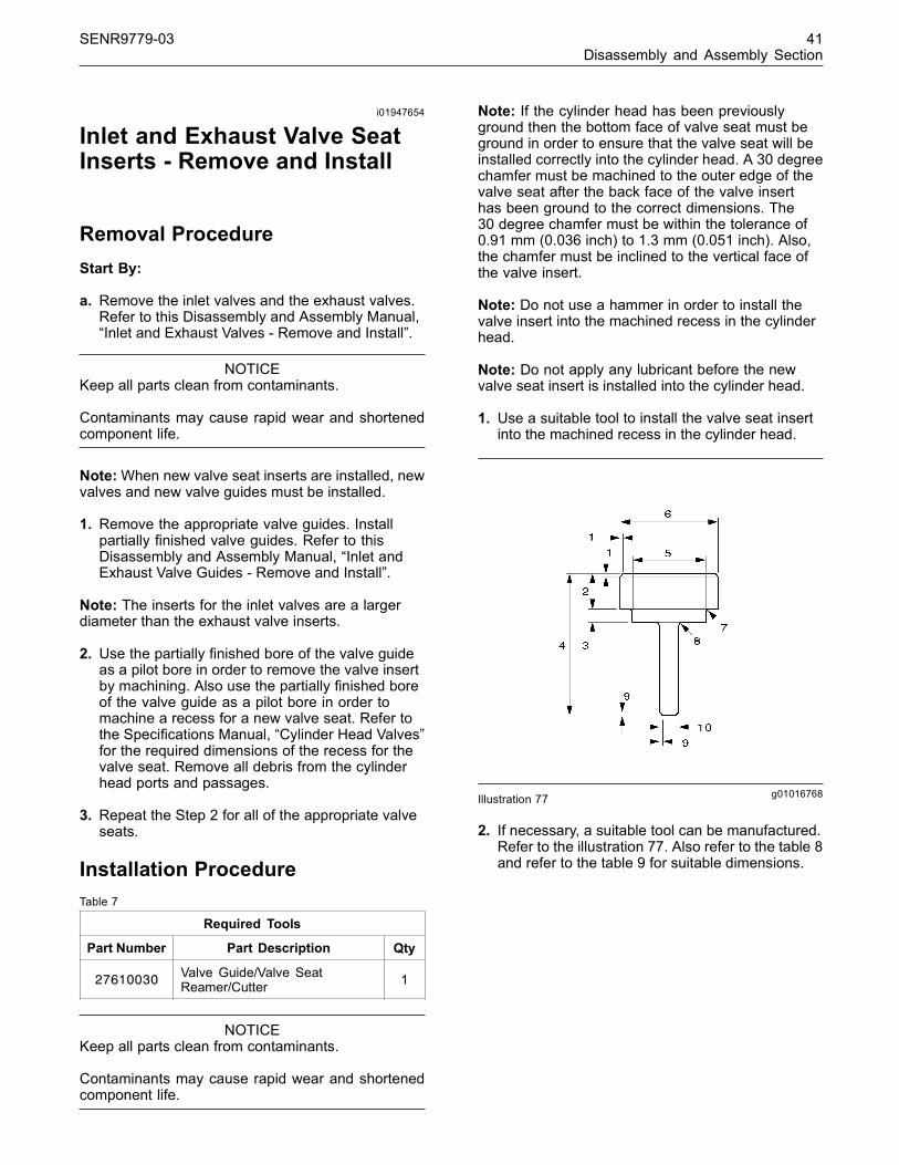
SENR9779-03 41Disassembly and Assembly Section
i01947654
Inlet and Exhaust Valve SeatInserts - Remove and Install
Removal ProcedureStart By:
a. Remove the inlet valves and the exhaust valves.Refer to this Disassembly and Assembly Manual,“Inlet and Exhaust Valves - Remove and Install”.
NOTICEKeep all parts clean from contaminants.
Contaminants may cause rapid wear and shortenedcomponent life.
Note:When new valve seat inserts are installed, newvalves and new valve guides must be installed.
1. Remove the appropriate valve guides. Installpartially finished valve guides. Refer to thisDisassembly and Assembly Manual, “Inlet andExhaust Valve Guides - Remove and Install”.
Note: The inserts for the inlet valves are a largerdiameter than the exhaust valve inserts.
2. Use the partially finished bore of the valve guideas a pilot bore in order to remove the valve insertby machining. Also use the partially finished boreof the valve guide as a pilot bore in order tomachine a recess for a new valve seat. Refer tothe Specifications Manual, “Cylinder Head Valves”for the required dimensions of the recess for thevalve seat. Remove all debris from the cylinderhead ports and passages.
3. Repeat the Step 2 for all of the appropriate valveseats.
Installation ProcedureTable 7
Required Tools
Part Number Part Description Qty
27610030 Valve Guide/Valve SeatReamer/Cutter 1
NOTICEKeep all parts clean from contaminants.
Contaminants may cause rapid wear and shortenedcomponent life.
Note: If the cylinder head has been previouslyground then the bottom face of valve seat must beground in order to ensure that the valve seat will beinstalled correctly into the cylinder head. A 30 degreechamfer must be machined to the outer edge of thevalve seat after the back face of the valve inserthas been ground to the correct dimensions. The30 degree chamfer must be within the tolerance of0.91 mm (0.036 inch) to 1.3 mm (0.051 inch). Also,the chamfer must be inclined to the vertical face ofthe valve insert.
Note: Do not use a hammer in order to install thevalve insert into the machined recess in the cylinderhead.
Note: Do not apply any lubricant before the newvalve seat insert is installed into the cylinder head.
1. Use a suitable tool to install the valve seat insertinto the machined recess in the cylinder head.
g01016768Illustration 77
2. If necessary, a suitable tool can be manufactured.Refer to the illustration 77. Also refer to the table 8and refer to the table 9 for suitable dimensions.
This document has been printed from SPI². Not for Resale
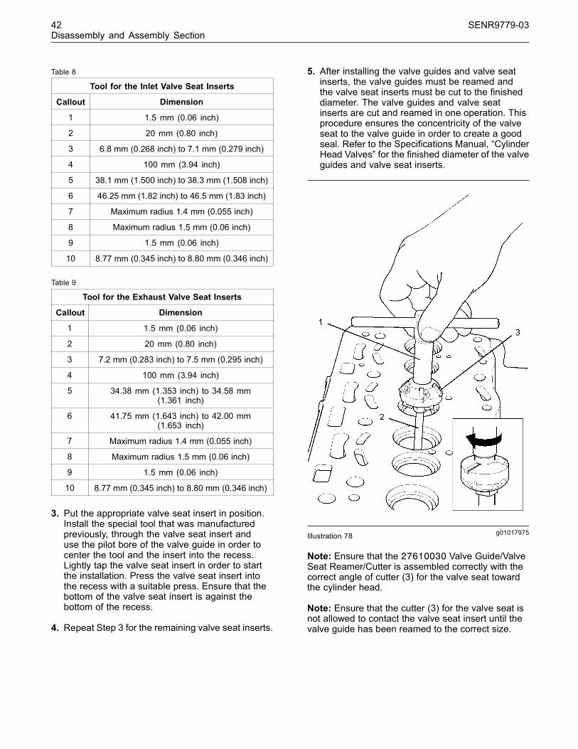
42 SENR9779-03Disassembly and Assembly Section
Table 8
Tool for the Inlet Valve Seat Inserts
Callout Dimension
1 1.5 mm (0.06 inch)
2 20 mm (0.80 inch)
3 6.8 mm (0.268 inch) to 7.1 mm (0.279 inch)
4 100 mm (3.94 inch)
5 38.1 mm (1.500 inch) to 38.3 mm (1.508 inch)
6 46.25 mm (1.82 inch) to 46.5 mm (1.83 inch)
7 Maximum radius 1.4 mm (0.055 inch)
8 Maximum radius 1.5 mm (0.06 inch)
9 1.5 mm (0.06 inch)
10 8.77 mm (0.345 inch) to 8.80 mm (0.346 inch)
Table 9
Tool for the Exhaust Valve Seat Inserts
Callout Dimension
1 1.5 mm (0.06 inch)
2 20 mm (0.80 inch)
3 7.2 mm (0.283 inch) to 7.5 mm (0.295 inch)
4 100 mm (3.94 inch)
5 34.38 mm (1.353 inch) to 34.58 mm(1.361 inch)
6 41.75 mm (1.643 inch) to 42.00 mm(1.653 inch)
7 Maximum radius 1.4 mm (0.055 inch)
8 Maximum radius 1.5 mm (0.06 inch)
9 1.5 mm (0.06 inch)
10 8.77 mm (0.345 inch) to 8.80 mm (0.346 inch)
3. Put the appropriate valve seat insert in position.Install the special tool that was manufacturedpreviously, through the valve seat insert anduse the pilot bore of the valve guide in order tocenter the tool and the insert into the recess.Lightly tap the valve seat insert in order to startthe installation. Press the valve seat insert intothe recess with a suitable press. Ensure that thebottom of the valve seat insert is against thebottom of the recess.
4. Repeat Step 3 for the remaining valve seat inserts.
5. After installing the valve guides and valve seatinserts, the valve guides must be reamed andthe valve seat inserts must be cut to the finisheddiameter. The valve guides and valve seatinserts are cut and reamed in one operation. Thisprocedure ensures the concentricity of the valveseat to the valve guide in order to create a goodseal. Refer to the Specifications Manual, “CylinderHead Valves” for the finished diameter of the valveguides and valve seat inserts.
g01017975Illustration 78
Note: Ensure that the 27610030 Valve Guide/ValveSeat Reamer/Cutter is assembled correctly with thecorrect angle of cutter (3) for the valve seat towardthe cylinder head.
Note: Ensure that the cutter (3) for the valve seat isnot allowed to contact the valve seat insert until thevalve guide has been reamed to the correct size.
This document has been printed from SPI². Not for Resale

SENR9779-03 43Disassembly and Assembly Section
6. Set the diameter of the cutter (3) to the correctsize for the valve seat to be cut. Refer to theSpecifications Manual, “Cylinder Head Valves” forthe correct diameter. Position the reamer (2) of thetool (1) into the appropriate valve guide. Carefullyturn the handle in a clockwise direction andgradually move the reamer (2) into the valve guideuntil the valve guide is reamed to the finished size.
7. Continue to turn the handle in a clockwise directionin order to cut the valve seat insert. Remove theminimum amount of material in order to ensure agood valve seat. Keep the valve seat as narrowas possible.
8. Remove the tool (1). Clean the debris from thevalve guide and the valve seat.
9. Repeat Step 6 to Step 8 in order to cut all of theappropriate valve seats.
End By:
a. Install the inlet valves and the exhaust valves.Refer to this Disassembly and Assembly Manual,“Inlet and Exhaust Valves - Remove and Install”.
i02262593
Engine Oil Filter Base -Remove and Install
Removal Procedure for an Oil Filterwith a Separate Filter ElementNote: This procedure is for the removal of an oilfilter with an oil filter housing and a separate oil filterelement.
Note: The oil filter can be installed vertically or the oilfilter can be installed horizontally.
NOTICEKeep all parts clean from contaminants.
Contaminants may cause rapid wear and shortenedcomponent life.
NOTICECare must be taken to ensure that fluids are containedduring performance of inspection, maintenance, test-ing, adjusting and repair of the product. Be prepared tocollect the fluid with suitable containers before open-ing any compartment or disassembling any compo-nent containing fluids.
Dispose of all fluids according to local regulations andmandates.
1. Remove all dirt, oil, and grease from the engineoil filter assembly and from the drain plug of theengine oil pan. Place a suitable container beneaththe drain plug of the engine oil pan.
2. Operate the engine until the engine is warm. Stopthe engine.
3. Remove the oil drain plug and the O-ring fromthe engine oil pan. Drain the engine oil into thecontainer for storage or disposal.
g01018261Illustration 79Typical example
Note: The drain plug (1) in the horizontal type of oilfilter is installed in the filter head (4) instead of the oilfilter housing (3). Do not remove the drain plug (1)from this type of oil filter.
4. Place a suitable container beneath the drain plug(1) in the oil filter housing (3). Remove the drainplug (1) from the oil filter housing (3) and removethe O-ring from the drain plug (1). Discard theO-ring. Collect any engine oil that drains from theoil filter housing (3).
5. Install a ratchet with a 1/2 inch square drive intothe recess (2) in the base of the oil filter housing(3) in order to remove the oil filter housing.
This document has been printed from SPI². Not for Resale

44 SENR9779-03Disassembly and Assembly Section
g01018307Illustration 80Typical example
6. Remove the oil filter element (6) from the oil filterhousing (3). Remove the O-ring (7) from the oilfilter housing (3). Discard the O-ring (7).
Note: Step 1 to Step 6 is the procedure for removingthe oil filter element. Step 6 to Step 9 is the additionalprocedure for removing the oil filter base (4).
g01018337Illustration 81
Typical example
7. Remove the setscrews (5).
8. Remove the engine oil filter base (4) from thecylinder block. Remove the joint (8) and discardthe joint.
9. If necessary, remove the plug (9) and the O-ring.
10. If necessary, remove the plug (10) and the O-ring.
Installation Procedure for an OilFilter with a Separate Filter Element
NOTICEKeep all parts clean from contaminants.
Contaminants may cause rapid wear and shortenedcomponent life.
Note: Step 1 to Step 5 is the procedure for installingthe oil filter base if the oil filter base was previouslyremoved. Step 6 to Step 11 is the procedure forinstalling the oil filter element.
g01018337Illustration 82
Typical example
1. Clean the oil passages within the oil filter base (4).Clean the mating surfaces of the cylinder blockand the engine oil filter base (4).
2. Inspect the O-ring for the plug (10) if the plug wasremoved from the oil filter base (4). If necessary,replace the O-ring. Install the O-ring and the plug(10) into the oil filter base (4). Tighten the plug(10) to a torque of 12 N·m (9 lb ft).
3. Inspect the O-ring for the plug (9) if the plug wasremoved from the oil filter base (4). If necessary,replace the O-ring. Install the O-ring and the plug(9) into the oil filter base (4). Tighten the plug (9)to a torque of 12 N·m (9 lb ft).
Note: New setscrews (5) have sealant on the first13 mm (0.5 inch) of the threads. In order to reusethe old setscrews (5), clean the old sealant fromthe setscrews and apply 21820117 POWERPARTThreadlock and Nutlock to the setscrews.
Note: Do not lubricate the new joint (8).
4. Install the setscrews (5) into the oil filter base (4).Install a new joint (8) onto the setscrews (5). Installthe setscrews (5) into the cylinder block.
This document has been printed from SPI². Not for Resale
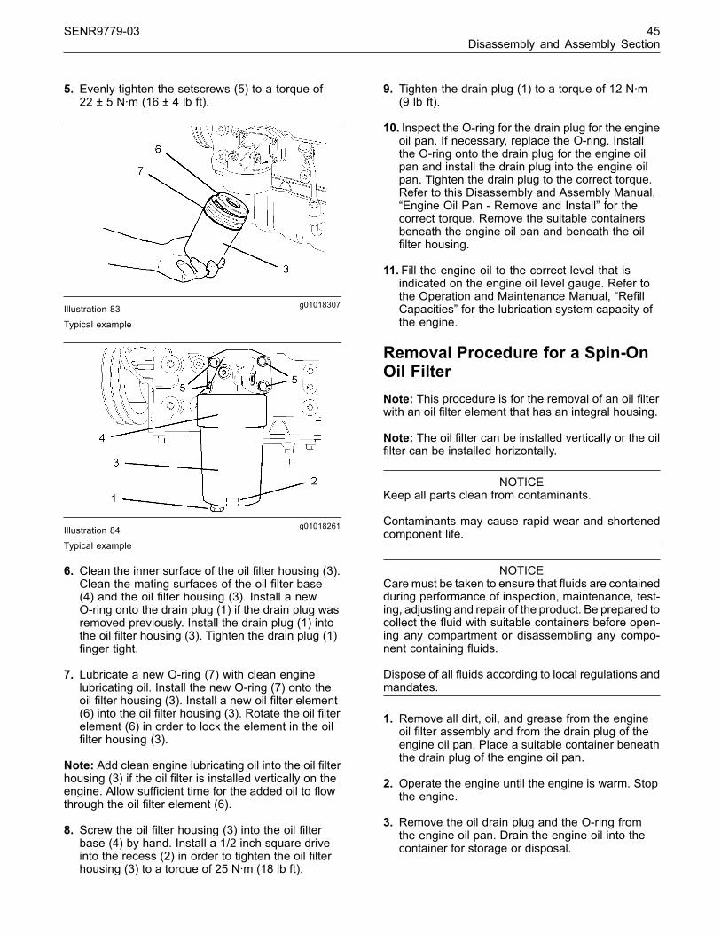
SENR9779-03 45Disassembly and Assembly Section
5. Evenly tighten the setscrews (5) to a torque of22 ± 5 N·m (16 ± 4 lb ft).
g01018307Illustration 83Typical example
g01018261Illustration 84
Typical example
6. Clean the inner surface of the oil filter housing (3).Clean the mating surfaces of the oil filter base(4) and the oil filter housing (3). Install a newO-ring onto the drain plug (1) if the drain plug wasremoved previously. Install the drain plug (1) intothe oil filter housing (3). Tighten the drain plug (1)finger tight.
7. Lubricate a new O-ring (7) with clean enginelubricating oil. Install the new O-ring (7) onto theoil filter housing (3). Install a new oil filter element(6) into the oil filter housing (3). Rotate the oil filterelement (6) in order to lock the element in the oilfilter housing (3).
Note: Add clean engine lubricating oil into the oil filterhousing (3) if the oil filter is installed vertically on theengine. Allow sufficient time for the added oil to flowthrough the oil filter element (6).
8. Screw the oil filter housing (3) into the oil filterbase (4) by hand. Install a 1/2 inch square driveinto the recess (2) in order to tighten the oil filterhousing (3) to a torque of 25 N·m (18 lb ft).
9. Tighten the drain plug (1) to a torque of 12 N·m(9 lb ft).
10. Inspect the O-ring for the drain plug for the engineoil pan. If necessary, replace the O-ring. Installthe O-ring onto the drain plug for the engine oilpan and install the drain plug into the engine oilpan. Tighten the drain plug to the correct torque.Refer to this Disassembly and Assembly Manual,“Engine Oil Pan - Remove and Install” for thecorrect torque. Remove the suitable containersbeneath the engine oil pan and beneath the oilfilter housing.
11. Fill the engine oil to the correct level that isindicated on the engine oil level gauge. Refer tothe Operation and Maintenance Manual, “RefillCapacities” for the lubrication system capacity ofthe engine.
Removal Procedure for a Spin-OnOil FilterNote: This procedure is for the removal of an oil filterwith an oil filter element that has an integral housing.
Note: The oil filter can be installed vertically or the oilfilter can be installed horizontally.
NOTICEKeep all parts clean from contaminants.
Contaminants may cause rapid wear and shortenedcomponent life.
NOTICECare must be taken to ensure that fluids are containedduring performance of inspection, maintenance, test-ing, adjusting and repair of the product. Be prepared tocollect the fluid with suitable containers before open-ing any compartment or disassembling any compo-nent containing fluids.
Dispose of all fluids according to local regulations andmandates.
1. Remove all dirt, oil, and grease from the engineoil filter assembly and from the drain plug of theengine oil pan. Place a suitable container beneaththe drain plug of the engine oil pan.
2. Operate the engine until the engine is warm. Stopthe engine.
3. Remove the oil drain plug and the O-ring fromthe engine oil pan. Drain the engine oil into thecontainer for storage or disposal.
This document has been printed from SPI². Not for Resale

46 SENR9779-03Disassembly and Assembly Section
g01018706Illustration 85Typical example
4. Place a suitable container beneath the oil filterelement (11).
5. Use a suitable strap wrench in order to remove theoil filter element (11). Discard the oil filter element(11) in a suitable manner.
Note: Step 1 to Step 5 is the procedure for removingthe oil filter element (11). Step 6 to Step 9 is theadditional procedure for removing the oil filter base(12).
6. Remove the setscrews (13).
7. Remove the engine oil filter base (12) from thecylinder block. Remove the joint (14) and discardthe joint.
8. If necessary, remove the adapter (15) from theoil filter base (12).
9. If necessary, remove the plug (16) and the O-ring.
10. If necessary, remove the plug (17) and the O-ring.
Installation Procedure for aSpin-On Oil Filter
NOTICEKeep all parts clean from contaminants.
Contaminants may cause rapid wear and shortenedcomponent life.
Note: Step 1 to Step 6 is the procedure for installingthe oil filter base if the oil filter base was previouslyremoved. Step 7 to Step 10 is the procedure forinstalling the oil filter element.
g01018706Illustration 86Typical example
1. Clean the oil passages within the oil filter base(12). Clean the mating surfaces of the cylinderblock and the engine oil filter base (12).
2. Inspect the adapter (15) if the adapter wasremoved from the oil filter base (12). Apply21820117 Powerpart to the last 10 mm(0.34 inch) of the thread on the adapter. Installthe adapter (15) into the oil filter base (12).Tighten the adapter (15) to a torque of 28 ± 4 N·m(20.7 ± 3 lb ft).
3. Inspect the O-ring for the plug (17) if the plug wasremoved from the oil filter base (12). If necessary,replace the O-ring. Install the O-ring and the plug(17) into the oil filter base (12). Tighten the plug(17) to a torque of 12 N·m (9 lb ft).
4. Inspect the O-ring for the plug (16) if the plug wasremoved from the oil filter base (12). If necessary,replace the O-ring. Install the O-ring and the plug(16) into the oil filter base (12). Tighten the plug(16) to a torque of 12 N·m (9 lb ft).
Note: New setscrews (13) have sealant on the first13 mm (0.5 inch) of the threads. In order to reusethe old setscrews (13), clean the old sealant fromthe setscrews and apply 21820117 POWERPARTThreadlock and Nutlock to the setscrews.
Note: Do not lubricate the new joint (14).
5. Install the setscrews (13) into the oil filter base(12). Install a new joint (14) onto the setscrews(13). Install the setscrews (13) into the cylinderblock.
6. Evenly tighten the setscrews (13) to a torque of22 ± 5 N·m (16 ± 4 lb ft).
7. Clean the mating surface of the oil filter base (12)to the oil filter element (11).
This document has been printed from SPI². Not for Resale

SENR9779-03 47Disassembly and Assembly Section
g01018743Illustration 87
8. Lubricate the top of the O-ring (18) with cleanengine lubricating oil. Spin the new oil filterelement (11) onto the adapter (15). Tighten theoil filter element (11) by hand. Do not use a strapwrench to tighten the oil filter element (11).
9. Inspect the O-ring for the drain plug for the engineoil pan. If necessary, replace the O-ring. Installthe O-ring onto the drain plug for the engine oilpan and install the drain plug into the engine oilpan. Tighten the drain plug to the correct torque.Refer to this Disassembly and Assembly Manual,“Engine Oil Pan - Remove and Install” for thecorrect torque. Remove the suitable containersbeneath the engine oil pan and beneath the oilfilter housing.
10. Fill the engine oil to the correct level that isindicated on the engine oil level gauge. Refer tothe Operation and Maintenance Manual, “RefillCapacities” for the lubrication system capacity ofthe engine.
i02259834
Engine Oil Cooler - Remove
Removal Procedure for ThreeCylinder Engine
NOTICEKeep all parts clean from contaminants.
Contaminants may cause rapid wear and shortenedcomponent life.
NOTICECare must be taken to ensure that fluids are containedduring performance of inspection, maintenance, test-ing, adjusting and repair of the product. Be prepared tocollect the fluid with suitable containers before open-ing any compartment or disassembling any compo-nent containing fluids.
Dispose of all fluids according to local regulations andmandates.
g01041195Illustration 88
g01041194Illustration 89
This document has been printed from SPI². Not for Resale
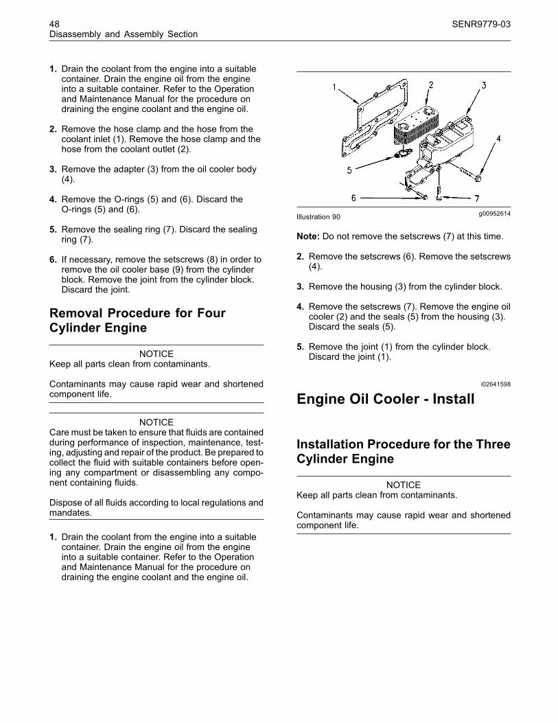
48 SENR9779-03Disassembly and Assembly Section
1. Drain the coolant from the engine into a suitablecontainer. Drain the engine oil from the engineinto a suitable container. Refer to the Operationand Maintenance Manual for the procedure ondraining the engine coolant and the engine oil.
2. Remove the hose clamp and the hose from thecoolant inlet (1). Remove the hose clamp and thehose from the coolant outlet (2).
3. Remove the adapter (3) from the oil cooler body(4).
4. Remove the O-rings (5) and (6). Discard theO-rings (5) and (6).
5. Remove the sealing ring (7). Discard the sealingring (7).
6. If necessary, remove the setscrews (8) in order toremove the oil cooler base (9) from the cylinderblock. Remove the joint from the cylinder block.Discard the joint.
Removal Procedure for FourCylinder Engine
NOTICEKeep all parts clean from contaminants.
Contaminants may cause rapid wear and shortenedcomponent life.
NOTICECare must be taken to ensure that fluids are containedduring performance of inspection, maintenance, test-ing, adjusting and repair of the product. Be prepared tocollect the fluid with suitable containers before open-ing any compartment or disassembling any compo-nent containing fluids.
Dispose of all fluids according to local regulations andmandates.
1. Drain the coolant from the engine into a suitablecontainer. Drain the engine oil from the engineinto a suitable container. Refer to the Operationand Maintenance Manual for the procedure ondraining the engine coolant and the engine oil.
g00952614Illustration 90
Note: Do not remove the setscrews (7) at this time.
2. Remove the setscrews (6). Remove the setscrews(4).
3. Remove the housing (3) from the cylinder block.
4. Remove the setscrews (7). Remove the engine oilcooler (2) and the seals (5) from the housing (3).Discard the seals (5).
5. Remove the joint (1) from the cylinder block.Discard the joint (1).
i02641598
Engine Oil Cooler - Install
Installation Procedure for the ThreeCylinder Engine
NOTICEKeep all parts clean from contaminants.
Contaminants may cause rapid wear and shortenedcomponent life.
This document has been printed from SPI². Not for Resale

SENR9779-03 49Disassembly and Assembly Section
g01041195Illustration 91
1. Clean the mating surfaces of the oil cooler base(9) and the oil cooler body (4). If the oil coolerbase (9) was removed, clean the mating surfacesof the oil cooler base and the cylinder block.
g01041030Illustration 92
Tightening sequence
Note: Do not use sealant on the new joint betweenthe cylinder block and the oil cooler base (9).
2. If the oil cooler base (9) was removed from thecylinder block, install setscrews into setscrewholes (1) and (6) in the oil cooler base. Install anew joint onto the two setscrews and secure theoil cooler base (9) to the cylinder block. Installthe remainder of the setscrews (8). Tighten thesetscrews (8) in the sequence 1, 2, 3, 4, 5, and6 to a torque of 22 N·m (16 lb ft). Refer to theillustration 92.
g01041194Illustration 93
3. Install new O-rings (5) and (6) onto the oil coolerbody (4). Position the oil cooler body (4) onto theoil cooler base (9).
4. Install a new sealing ring (7) onto the adapter (3).Install the adapter (3) through the oil cooler body(4) and into the oil cooler base (9). Tighten theadapter (3) to a torque of 57 N·m (42 lb ft).
5. Install the appropriate hose to the coolant outlet(2). Tighten the hose clamp to a torque of 3.5 N·m(31 lb in).
6. Install the appropriate hose to the coolant inlet (1).Tighten the hose clamp to a torque of 3.5 N·m(31 lb in).
7. Fill the cooling system with coolant. Fill thelubrication system with engine oil. Refer to theOperation and Maintenance Manual, “RefillCapacities” for the cooling system capacity andfor the lubrication system capacity of the engine.
This document has been printed from SPI². Not for Resale
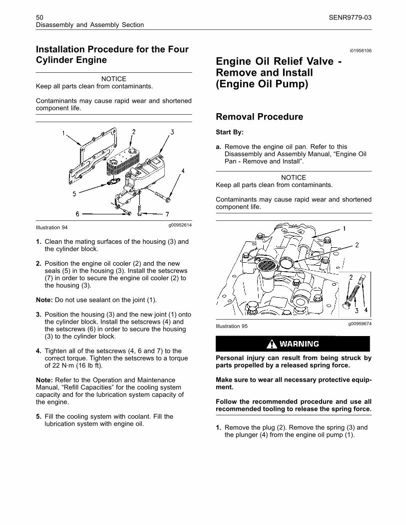
50 SENR9779-03Disassembly and Assembly Section
Installation Procedure for the FourCylinder Engine
NOTICEKeep all parts clean from contaminants.
Contaminants may cause rapid wear and shortenedcomponent life.
g00952614Illustration 94
1. Clean the mating surfaces of the housing (3) andthe cylinder block.
2. Position the engine oil cooler (2) and the newseals (5) in the housing (3). Install the setscrews(7) in order to secure the engine oil cooler (2) tothe housing (3).
Note: Do not use sealant on the joint (1).
3. Position the housing (3) and the new joint (1) ontothe cylinder block. Install the setscrews (4) andthe setscrews (6) in order to secure the housing(3) to the cylinder block.
4. Tighten all of the setscrews (4, 6 and 7) to thecorrect torque. Tighten the setscrews to a torqueof 22 N·m (16 lb ft).
Note: Refer to the Operation and MaintenanceManual, “Refill Capacities” for the cooling systemcapacity and for the lubrication system capacity ofthe engine.
5. Fill the cooling system with coolant. Fill thelubrication system with engine oil.
i01958106
Engine Oil Relief Valve -Remove and Install(Engine Oil Pump)
Removal ProcedureStart By:
a. Remove the engine oil pan. Refer to thisDisassembly and Assembly Manual, “Engine OilPan - Remove and Install”.
NOTICEKeep all parts clean from contaminants.
Contaminants may cause rapid wear and shortenedcomponent life.
g00959674Illustration 95
Personal injury can result from being struck byparts propelled by a released spring force.
Make sure to wear all necessary protective equip-ment.
Follow the recommended procedure and use allrecommended tooling to release the spring force.
1. Remove the plug (2). Remove the spring (3) andthe plunger (4) from the engine oil pump (1).
This document has been printed from SPI². Not for Resale
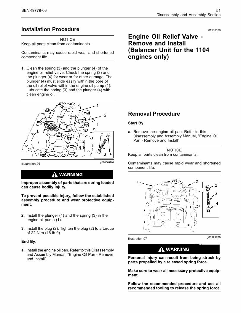
SENR9779-03 51Disassembly and Assembly Section
Installation Procedure
NOTICEKeep all parts clean from contaminants.
Contaminants may cause rapid wear and shortenedcomponent life.
1. Clean the spring (3) and the plunger (4) of theengine oil relief valve. Check the spring (3) andthe plunger (4) for wear or for other damage. Theplunger (4) must slide easily within the bore ofthe oil relief valve within the engine oil pump (1).Lubricate the spring (3) and the plunger (4) withclean engine oil.
g00959674Illustration 96
Improper assembly of parts that are spring loadedcan cause bodily injury.
To prevent possible injury, follow the establishedassembly procedure and wear protective equip-ment.
2. Install the plunger (4) and the spring (3) in theengine oil pump (1).
3. Install the plug (2). Tighten the plug (2) to a torqueof 22 N·m (16 lb ft).
End By:
a. Install the engine oil pan. Refer to this Disassemblyand Assembly Manual, “Engine Oil Pan - Removeand Install”.
i01958108
Engine Oil Relief Valve -Remove and Install(Balancer Unit for the 1104engines only)
Removal ProcedureStart By:
a. Remove the engine oil pan. Refer to thisDisassembly and Assembly Manual, “Engine OilPan - Remove and Install”.
NOTICEKeep all parts clean from contaminants.
Contaminants may cause rapid wear and shortenedcomponent life.
g00979780Illustration 97
Personal injury can result from being struck byparts propelled by a released spring force.
Make sure to wear all necessary protective equip-ment.
Follow the recommended procedure and use allrecommended tooling to release the spring force.
This document has been printed from SPI². Not for Resale
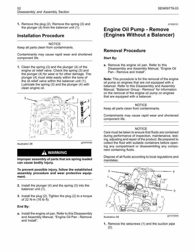
52 SENR9779-03Disassembly and Assembly Section
1. Remove the plug (2). Remove the spring (3) andthe plunger (4) from the balancer unit (1).
Installation Procedure
NOTICEKeep all parts clean from contaminants.
Contaminants may cause rapid wear and shortenedcomponent life.
1. Clean the spring (3) and the plunger (4) of theengine oil relief valve. Check the spring (3) andthe plunger (4) for wear or for other damage. Theplunger (4) must slide easily within the bore ofthe oil relief valve within the balancer unit (1).Lubricate the spring (3) and the plunger (4) withclean engine oil.
g00979780Illustration 98
Improper assembly of parts that are spring loadedcan cause bodily injury.
To prevent possible injury, follow the establishedassembly procedure and wear protective equip-ment.
2. Install the plunger (4) and the spring (3) into thebalancer unit (1).
3. Install the plug (2). Tighten the plug (2) to a torqueof 22 N·m (16 lb ft).
End By:
a. Install the engine oil pan. Refer to this Disassemblyand Assembly Manual, “Engine Oil Pan - Removeand Install”.
i01958101
Engine Oil Pump - Remove(Engines Without a Balancer)
Removal ProcedureStart By:
a. Remove the engine oil pan. Refer to thisDisassembly and Assembly Manual, “Engine OilPan - Remove and Install”.
Note: This procedure is for the removal of the engineoil pump on engines that are not equipped with abalancer. Refer to this Disassembly and AssemblyManual, “Balancer Group - Remove” for informationon the removal of the engine oil pump on enginesthat are equipped with a balancer.
NOTICEKeep all parts clean from contaminants.
Contaminants may cause rapid wear and shortenedcomponent life.
NOTICECare must be taken to ensure that fluids are containedduring performance of inspection, maintenance, test-ing, adjusting and repair of the product. Be prepared tocollect the fluid with suitable containers before open-ing any compartment or disassembling any compo-nent containing fluids.
Dispose of all fluids according to local regulations andmandates.
g01019045Illustration 99
1. Remove the setscrews (1) and the suction pipe(2).
This document has been printed from SPI². Not for Resale

SENR9779-03 53Disassembly and Assembly Section
2. Remove the setscrews (3). Remove the assemblyof the engine oil pump (4) from the cylinder block.
3. If necessary, remove the pressure relief valve (5)from the assembly of the engine oil pump (4).Refer to this Disassembly and Assembly Manual,“Engine Oil Relief Vave - Remove and Install”.
g01019047Illustration 100
4. Remove the setscrews (6). Remove the engineoil pump (7) from the assembly of the engine oilpump (4).
5. If necessary, remove the setscrews and removethe front cover assembly from the engine oil pump(7) in order to inspect the components within theengine oil pump.
i01958102
Engine Oil Pump - Install(Engines Without a Balancer)
Installation ProcedureNote: This procedure is for the installation of theengine oil pump on engines that are not equippedwith a balancer. Refer to this Disassembly andAssembly Manual, “Balancer Group - Install” forinformation on the installation of the engine oil pumpon engines that are equipped with a balancer.
NOTICEKeep all parts clean from contaminants.
Contaminants may cause rapid wear and shortenedcomponent life.
NOTICEIf any of the parts on the engine oil pump are worn ordamaged, the entire pump must be replaced.
1. Clean all of the internal components of the oilpump if the front cover of the oil pump waspreviously removed in order to inspect the internalcomponents. Check the internal components forwear and for other damage. Check the clearancebetween the outer rotor of the oil pump and theoil pump body. Check the clearance between theouter rotor and the inner rotor. Check the endplay movement of the rotor. Refer to the SystemsOperation/Testing and Adjusting Manual, “EngineOil Pump - Inspect”. Replace the engine oil pumpif any of the components are worn or damaged.
2. Lubricate the inner rotor and the outer rotor of theengine oil pump with clean engine lubricating oil.Install the front cover of the engine oil pump ontothe body of the oil pump. Install the setscrews andtighten the setscrews in order to secure the frontcover to the body.
g01019312Illustration 101
3. Fill engine oil pump (6) with clean engine oil.
4. Install the engine oil pump (6) into the assemblyof the engine oil pump (4). Install the setscrews(7). Tighten the setscrews to a torque of 9 N·m(80 lb in).
5. Ensure that the dowel pin (8) and the hollow dowel(9) are correctly located in the cylinder block.Install the assembly of the engine oil pump (4)onto the dowels (8 and 9).
6. Install the setscrews (3). Tighten the setscrews toa torque of 44 N·m (32 lb ft).
7. Check the backlash between the idler gear (10)of the oil pump and the crankshaft gear. Refer tothe Specifications Manual, “Gear Group - Front”for further information.
This document has been printed from SPI². Not for Resale

54 SENR9779-03Disassembly and Assembly Section
g01019045Illustration 102
8. If the pressure relief valve (5) was removed, installthe pressure relief valve. Refer to this Disassemblyand Assembly Manual, “Engine Oil Relief Valve -Remove and Install” for further information.
9. Position the suction pipe (2) and install thesetscrews (1).
End By:
a. Install the engine oil pan. Refer to this Disassemblyand Assembly Manual, “Engine Oil Pan - Removeand Install”.
i01991657
Water Pump - Remove
Removal ProcedureStart By:
a. Remove the fan. Refer to this Disassembly andAssembly Manual, “Fan - Remove and Install”.
NOTICEKeep all parts clean from contaminants.
Contaminants may cause rapid wear and shortenedcomponent life.
NOTICECare must be taken to ensure that fluids are containedduring performance of inspection, maintenance, test-ing, adjusting and repair of the product. Be prepared tocollect the fluid with suitable containers before open-ing any compartment or disassembling any compo-nent containing fluids.
Dispose of all fluids according to local regulations andmandates.
1. Drain the coolant from the cooling system into asuitable container for storage or disposal.
2. Loosen the clamps and remove the hose from thewater pump inlet.
g00952695Illustration 103
3. Remove the setscrews (3) that fasten the waterpump (4) to the front housing (1).
4. If necessary, gently tap the water pump (4) with asoft hammer in order to loosen the water pump.
5. Remove the water pump (4). Remove the joint (2)from the front housing (1) and the water pump (4).Discard the joint (1).
i01962207
Water Pump - Disassemble
Disassembly ProcedureStart By:
a. Remove the water pump. Refer to thisDisassembly and Assembly Manual, “Water Pump- Remove and Install”.
This document has been printed from SPI². Not for Resale

SENR9779-03 55Disassembly and Assembly Section
NOTICEKeep all parts clean from contaminants.
Contaminants may cause rapid wear and shortenedcomponent life.
g01019550Illustration 104
1. Remove the setscrews (1) from the cover (2) ofthe water pump (3). Remove the joint between thecover (2) and the water pump (3). Discard the joint.
Note: All of the other setscrews are removed duringthe removal of the water pump.
g01019566Illustration 105
2. Drill twelve 6.35 mm (0.25 inch) holes betweenthe existing holes in the impeller (4). Break piecesfrom the impeller (4) in order to install a suitablepuller (5) with two legs onto the impeller. Removethe impeller (4) with the suitable puller (5).
g01020061Illustration 106
Note: It will be necessary to break the coolant seal(6) in order to remove the coolant seal from the waterpump (3).
3. Drill three 3.175 mm (0.125 inch) holes that areequally spaced into the coolant seal (6). Theholes should be drilled into the face of the coolantseal (6) that would have faced the impeller (4).Insert three 25.4 mm (1.00 inch) long self-tappingscrews into the drilled holes. Insert a suitable leverinto the coolant inlet of the water pump (3). Usethe suitable lever under the self-tapping screwsin order to evenly pull the coolant seal (6) off theshaft (7). If necessary, remove the center sleeveof the coolant seal from the shaft with a suitableextractor.
4. Remove the outer circlip (8) and discard the outercirclip. Remove the inner circlip (9) and discardthe inner circlip.
This document has been printed from SPI². Not for Resale
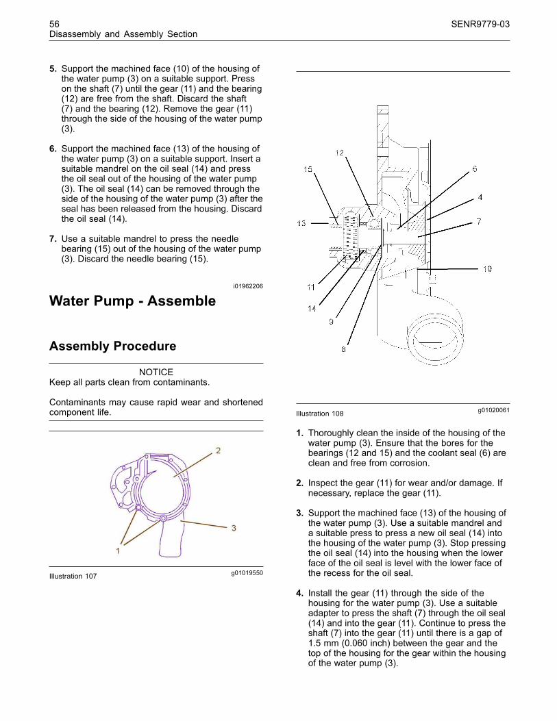
56 SENR9779-03Disassembly and Assembly Section
5. Support the machined face (10) of the housing ofthe water pump (3) on a suitable support. Presson the shaft (7) until the gear (11) and the bearing(12) are free from the shaft. Discard the shaft(7) and the bearing (12). Remove the gear (11)through the side of the housing of the water pump(3).
6. Support the machined face (13) of the housing ofthe water pump (3) on a suitable support. Insert asuitable mandrel on the oil seal (14) and pressthe oil seal out of the housing of the water pump(3). The oil seal (14) can be removed through theside of the housing of the water pump (3) after theseal has been released from the housing. Discardthe oil seal (14).
7. Use a suitable mandrel to press the needlebearing (15) out of the housing of the water pump(3). Discard the needle bearing (15).
i01962206
Water Pump - Assemble
Assembly Procedure
NOTICEKeep all parts clean from contaminants.
Contaminants may cause rapid wear and shortenedcomponent life.
g01019550Illustration 107
g01020061Illustration 108
1. Thoroughly clean the inside of the housing of thewater pump (3). Ensure that the bores for thebearings (12 and 15) and the coolant seal (6) areclean and free from corrosion.
2. Inspect the gear (11) for wear and/or damage. Ifnecessary, replace the gear (11).
3. Support the machined face (13) of the housing ofthe water pump (3). Use a suitable mandrel anda suitable press to press a new oil seal (14) intothe housing of the water pump (3). Stop pressingthe oil seal (14) into the housing when the lowerface of the oil seal is level with the lower face ofthe recess for the oil seal.
4. Install the gear (11) through the side of thehousing for the water pump (3). Use a suitableadapter to press the shaft (7) through the oil seal(14) and into the gear (11). Continue to press theshaft (7) into the gear (11) until there is a gap of1.5 mm (0.060 inch) between the gear and thetop of the housing for the gear within the housingof the water pump (3).
This document has been printed from SPI². Not for Resale
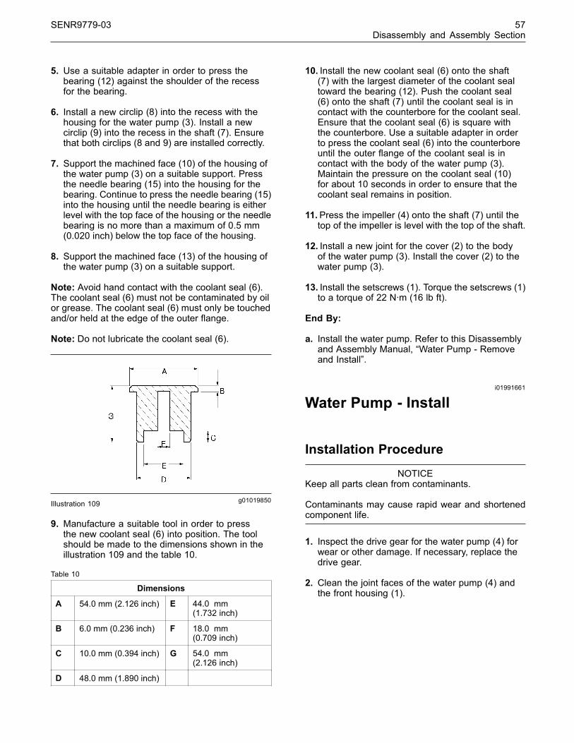
SENR9779-03 57Disassembly and Assembly Section
5. Use a suitable adapter in order to press thebearing (12) against the shoulder of the recessfor the bearing.
6. Install a new circlip (8) into the recess with thehousing for the water pump (3). Install a newcirclip (9) into the recess in the shaft (7). Ensurethat both circlips (8 and 9) are installed correctly.
7. Support the machined face (10) of the housing ofthe water pump (3) on a suitable support. Pressthe needle bearing (15) into the housing for thebearing. Continue to press the needle bearing (15)into the housing until the needle bearing is eitherlevel with the top face of the housing or the needlebearing is no more than a maximum of 0.5 mm(0.020 inch) below the top face of the housing.
8. Support the machined face (13) of the housing ofthe water pump (3) on a suitable support.
Note: Avoid hand contact with the coolant seal (6).The coolant seal (6) must not be contaminated by oilor grease. The coolant seal (6) must only be touchedand/or held at the edge of the outer flange.
Note: Do not lubricate the coolant seal (6).
g01019850Illustration 109
9. Manufacture a suitable tool in order to pressthe new coolant seal (6) into position. The toolshould be made to the dimensions shown in theillustration 109 and the table 10.
Table 10
Dimensions
A 54.0 mm (2.126 inch) E 44.0 mm(1.732 inch)
B 6.0 mm (0.236 inch) F 18.0 mm(0.709 inch)
C 10.0 mm (0.394 inch) G 54.0 mm(2.126 inch)
D 48.0 mm (1.890 inch)
10. Install the new coolant seal (6) onto the shaft(7) with the largest diameter of the coolant sealtoward the bearing (12). Push the coolant seal(6) onto the shaft (7) until the coolant seal is incontact with the counterbore for the coolant seal.Ensure that the coolant seal (6) is square withthe counterbore. Use a suitable adapter in orderto press the coolant seal (6) into the counterboreuntil the outer flange of the coolant seal is incontact with the body of the water pump (3).Maintain the pressure on the coolant seal (10)for about 10 seconds in order to ensure that thecoolant seal remains in position.
11.Press the impeller (4) onto the shaft (7) until thetop of the impeller is level with the top of the shaft.
12. Install a new joint for the cover (2) to the bodyof the water pump (3). Install the cover (2) to thewater pump (3).
13. Install the setscrews (1). Torque the setscrews (1)to a torque of 22 N·m (16 lb ft).
End By:
a. Install the water pump. Refer to this Disassemblyand Assembly Manual, “Water Pump - Removeand Install”.
i01991661
Water Pump - Install
Installation Procedure
NOTICEKeep all parts clean from contaminants.
Contaminants may cause rapid wear and shortenedcomponent life.
1. Inspect the drive gear for the water pump (4) forwear or other damage. If necessary, replace thedrive gear.
2. Clean the joint faces of the water pump (4) andthe front housing (1).
This document has been printed from SPI². Not for Resale
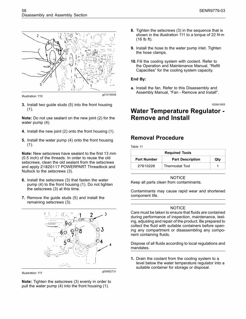
58 SENR9779-03Disassembly and Assembly Section
g01019549Illustration 110
3. Install two guide studs (5) into the front housing(1).
Note: Do not use sealant on the new joint (2) for thewater pump (4).
4. Install the new joint (2) onto the front housing (1).
5. Install the water pump (4) onto the front housing(1).
Note: New setscrews have sealant to the first 13 mm(0.5 inch) of the threads. In order to reuse the oldsetscrews, clean the old sealant from the setscrewsand apply 21820117 POWERPART Threadlock andNutlock to the setscrews (3).
6. Install the setscrews (3) that fasten the waterpump (4) to the front housing (1). Do not tightenthe setscrews (3) at this time.
7. Remove the guide studs (5) and install theremaining setscrews (3).
g00952731Illustration 111
Note: Tighten the setscrews (3) evenly in order topull the water pump (4) into the front housing (1).
8. Tighten the setscrews (3) in the sequence that isshown in the illustration 111 to a torque of 22 N·m(16 lb ft).
9. Install the hose to the water pump inlet. Tightenthe hose clamps.
10. Fill the cooling system with coolant. Refer tothe Operation and Maintenance Manual, “RefillCapacities” for the cooling system capacity.
End By:
a. Install the fan. Refer to this Disassembly andAssembly Manual, “Fan - Remove and Install”.
i02641605
Water Temperature Regulator -Remove and Install
Removal ProcedureTable 11
Required Tools
Part Number Part Description Qty
27610226 Thermostat Tool 1
NOTICEKeep all parts clean from contaminants.
Contaminants may cause rapid wear and shortenedcomponent life.
NOTICECare must be taken to ensure that fluids are containedduring performance of inspection, maintenance, test-ing, adjusting and repair of the product. Be prepared tocollect the fluid with suitable containers before open-ing any compartment or disassembling any compo-nent containing fluids.
Dispose of all fluids according to local regulations andmandates.
1. Drain the coolant from the cooling system to alevel below the water temperature regulator into asuitable container for storage or disposal.
This document has been printed from SPI². Not for Resale
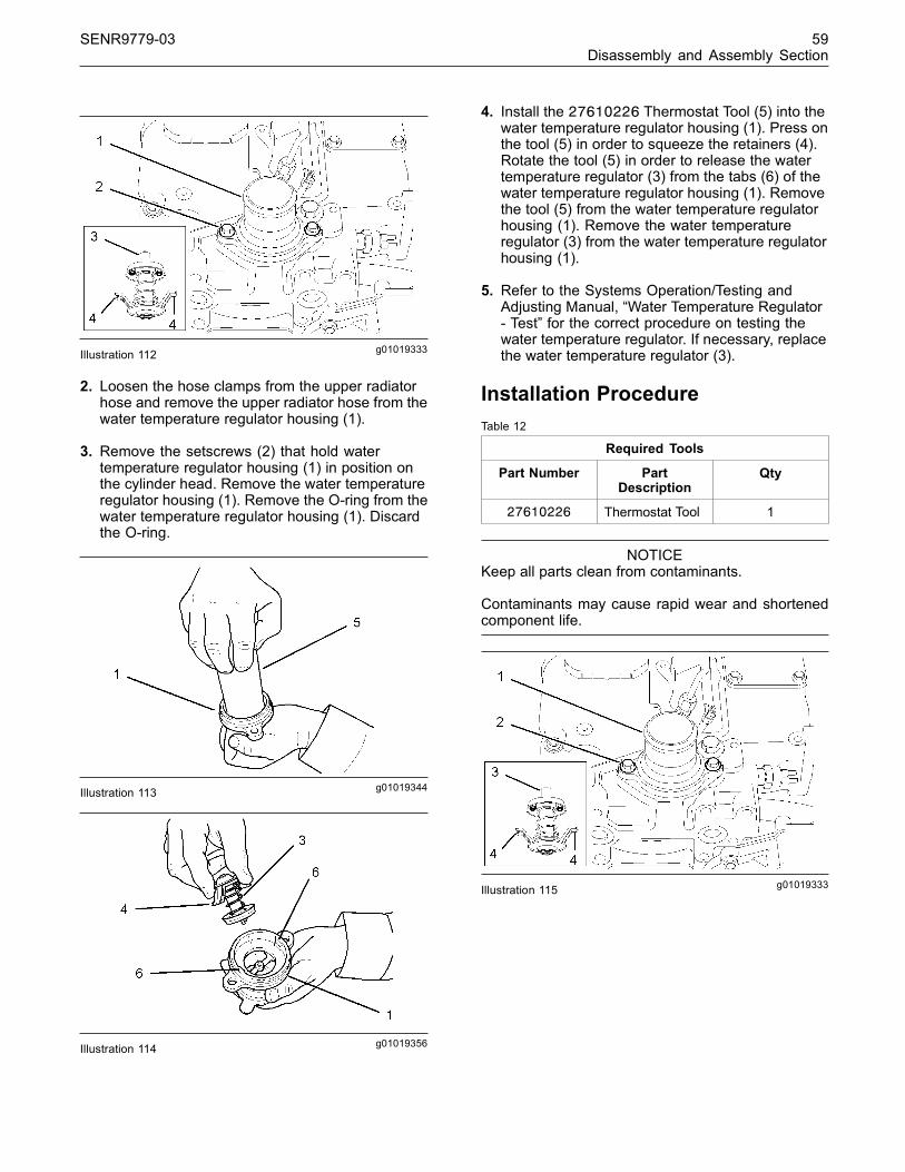
SENR9779-03 59Disassembly and Assembly Section
g01019333Illustration 112
2. Loosen the hose clamps from the upper radiatorhose and remove the upper radiator hose from thewater temperature regulator housing (1).
3. Remove the setscrews (2) that hold watertemperature regulator housing (1) in position onthe cylinder head. Remove the water temperatureregulator housing (1). Remove the O-ring from thewater temperature regulator housing (1). Discardthe O-ring.
g01019344Illustration 113
g01019356Illustration 114
4. Install the 27610226 Thermostat Tool (5) into thewater temperature regulator housing (1). Press onthe tool (5) in order to squeeze the retainers (4).Rotate the tool (5) in order to release the watertemperature regulator (3) from the tabs (6) of thewater temperature regulator housing (1). Removethe tool (5) from the water temperature regulatorhousing (1). Remove the water temperatureregulator (3) from the water temperature regulatorhousing (1).
5. Refer to the Systems Operation/Testing andAdjusting Manual, “Water Temperature Regulator- Test” for the correct procedure on testing thewater temperature regulator. If necessary, replacethe water temperature regulator (3).
Installation ProcedureTable 12
Required Tools
Part Number PartDescription
Qty
27610226 Thermostat Tool 1
NOTICEKeep all parts clean from contaminants.
Contaminants may cause rapid wear and shortenedcomponent life.
g01019333Illustration 115
This document has been printed from SPI². Not for Resale

60 SENR9779-03Disassembly and Assembly Section
g01019377Illustration 116
1. Clean the water temperature regulator housing(1). Ensure that the tabs (6) for the retainers (4)are clean. Ensure that the seat for the O-ring (7)is clean.
g01019381Illustration 117
2. The water temperature regulator (3) has two vents(8) that are opened and closed by a valve pin.These two vents (8) bleed hot water and/or airthrough the water temperature regulator (3) whenthe water temperature regulator is in the closedposition. Ensure that the valve pins (8) can movefreely in the vents.
3. Lubricate the new O-ring (7) with 21820221POWERPART Red Rubber Grease. Install theO-ring (7) into the appropriate groove in the watertemperature regulator housing (1).
g01019344Illustration 118
g01019356Illustration 119
4. Position the water temperature regulator (3) in thewater temperature regulator housing (1). Installthe 27610226 Thermostat Tool (5) in order tosqueeze the retainers (4). Rotate the tool (5) inorder to secure the water temperature regulator(3) into the water temperature regulator housing(1).
Note: The retainers (4) must be inserted behind thetabs of the water temperature regulator housing (1)in order to secure the water temperature regulator (3)during engine operation.
5. Ensure that the retainers (4) are correctly installedwithin the tabs (6). Position the water temperatureregulator housing (1) onto the cylinder head.
6. Install the setscrews (2) that fasten the watertemperature regulator housing (1) to the cylinderhead. Tighten the setscrews (2) to a torque of44 N·m (32 lb ft).
7. Install the upper radiator hose and tighten thehose clamps securely.
8. Fill the cooling system to the proper level. Referto the Operation and Maintenance Manual, “RefillCapacities” for further information.
This document has been printed from SPI². Not for Resale

SENR9779-03 61Disassembly and Assembly Section
i02259836
Flywheel - Remove
Removal Procedure
NOTICEKeep all parts clean from contaminants.
Contaminants may cause rapid wear and shortenedcomponent life.
g00905926Illustration 120
1. Remove the two setscrews (1).
g01020091Illustration 121Typical example
2. Install two suitable studs (2) as guides.
Note: The flywheel (3) is heavy. Use suitable liftingequipment to support the flywheel (3) before theremainder of the setscrews (1) are removed.
3. Remove the remaining setscrews (1) that secureflywheel (3) to the crankshaft and then removethe flywheel.
g01020099Illustration 122
4. Check the condition of the ring gear (4). Removethe ring gear (4) if the ring gear is worn ordamaged.
Note: Identify the orientation of the ring gear on theflywheel and the position of the chamfer on the teethfor the correct positioning when the new ring gearis installed.
5. Place the flywheel (3) and the ring gear (4) on asuitable support. Use a hammer and a chisel inorder to remove the ring gear (4) from the flywheel(3).
i02231069
Flywheel - Install
Installation Procedure
NOTICEKeep all parts clean from contaminants.
Contaminants may cause rapid wear and shortenedcomponent life.
Always wear protective gloves when handlingparts that have been heated.
1. Thoroughly clean the flywheel housing. Inspectthe crankshaft rear seal for leaks. If there are anyoil leaks refer to this Disassembly and AssemblyManual, “Crankshaft Rear Seal - Remove”.
This document has been printed from SPI². Not for Resale
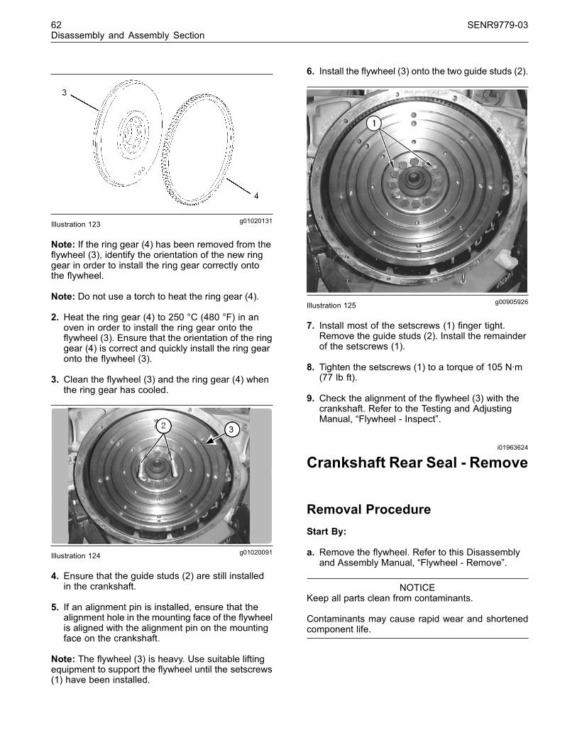
62 SENR9779-03Disassembly and Assembly Section
g01020131Illustration 123
Note: If the ring gear (4) has been removed from theflywheel (3), identify the orientation of the new ringgear in order to install the ring gear correctly ontothe flywheel.
Note: Do not use a torch to heat the ring gear (4).
2. Heat the ring gear (4) to 250 °C (480 °F) in anoven in order to install the ring gear onto theflywheel (3). Ensure that the orientation of the ringgear (4) is correct and quickly install the ring gearonto the flywheel (3).
3. Clean the flywheel (3) and the ring gear (4) whenthe ring gear has cooled.
g01020091Illustration 124
4. Ensure that the guide studs (2) are still installedin the crankshaft.
5. If an alignment pin is installed, ensure that thealignment hole in the mounting face of the flywheelis aligned with the alignment pin on the mountingface on the crankshaft.
Note: The flywheel (3) is heavy. Use suitable liftingequipment to support the flywheel until the setscrews(1) have been installed.
6. Install the flywheel (3) onto the two guide studs (2).
g00905926Illustration 125
7. Install most of the setscrews (1) finger tight.Remove the guide studs (2). Install the remainderof the setscrews (1).
8. Tighten the setscrews (1) to a torque of 105 N·m(77 lb ft).
9. Check the alignment of the flywheel (3) with thecrankshaft. Refer to the Testing and AdjustingManual, “Flywheel - Inspect”.
i01963624
Crankshaft Rear Seal - Remove
Removal ProcedureStart By:
a. Remove the flywheel. Refer to this Disassemblyand Assembly Manual, “Flywheel - Remove”.
NOTICEKeep all parts clean from contaminants.
Contaminants may cause rapid wear and shortenedcomponent life.
This document has been printed from SPI². Not for Resale
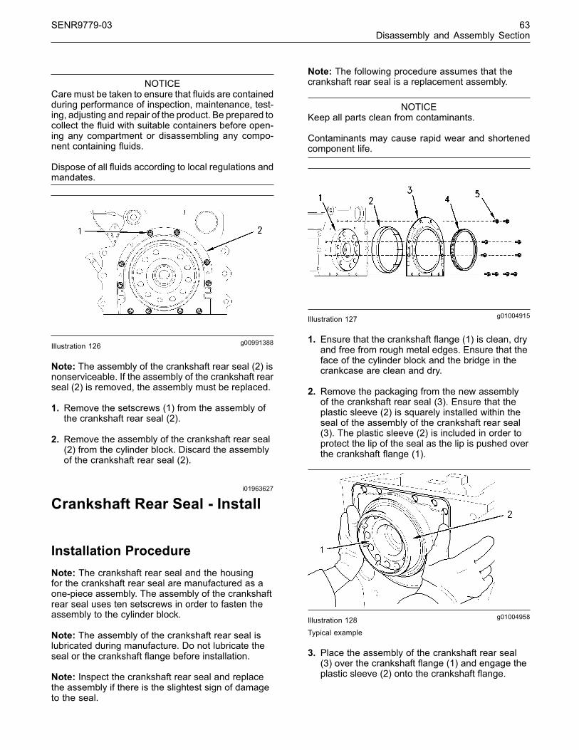
SENR9779-03 63Disassembly and Assembly Section
NOTICECare must be taken to ensure that fluids are containedduring performance of inspection, maintenance, test-ing, adjusting and repair of the product. Be prepared tocollect the fluid with suitable containers before open-ing any compartment or disassembling any compo-nent containing fluids.
Dispose of all fluids according to local regulations andmandates.
g00991388Illustration 126
Note: The assembly of the crankshaft rear seal (2) isnonserviceable. If the assembly of the crankshaft rearseal (2) is removed, the assembly must be replaced.
1. Remove the setscrews (1) from the assembly ofthe crankshaft rear seal (2).
2. Remove the assembly of the crankshaft rear seal(2) from the cylinder block. Discard the assemblyof the crankshaft rear seal (2).
i01963627
Crankshaft Rear Seal - Install
Installation ProcedureNote: The crankshaft rear seal and the housingfor the crankshaft rear seal are manufactured as aone-piece assembly. The assembly of the crankshaftrear seal uses ten setscrews in order to fasten theassembly to the cylinder block.
Note: The assembly of the crankshaft rear seal islubricated during manufacture. Do not lubricate theseal or the crankshaft flange before installation.
Note: Inspect the crankshaft rear seal and replacethe assembly if there is the slightest sign of damageto the seal.
Note: The following procedure assumes that thecrankshaft rear seal is a replacement assembly.
NOTICEKeep all parts clean from contaminants.
Contaminants may cause rapid wear and shortenedcomponent life.
g01004915Illustration 127
1. Ensure that the crankshaft flange (1) is clean, dryand free from rough metal edges. Ensure that theface of the cylinder block and the bridge in thecrankcase are clean and dry.
2. Remove the packaging from the new assemblyof the crankshaft rear seal (3). Ensure that theplastic sleeve (2) is squarely installed within theseal of the assembly of the crankshaft rear seal(3). The plastic sleeve (2) is included in order toprotect the lip of the seal as the lip is pushed overthe crankshaft flange (1).
g01004958Illustration 128
Typical example
3. Place the assembly of the crankshaft rear seal(3) over the crankshaft flange (1) and engage theplastic sleeve (2) onto the crankshaft flange.
This document has been printed from SPI². Not for Resale

64 SENR9779-03Disassembly and Assembly Section
g01004958Illustration 129Typical example
4. Ensure that the plastic sleeve (2) is engaged ontothe crankshaft flange (1). Push the assembly ofthe crankshaft rear seal (3) evenly and push theassembly smoothly onto the crankshaft flange (1)until the assembly is against the cylinder block.During this process, the plastic sleeve (2) will beforced out of the assembly of the crankshaft rearseal (3). Discard the plastic sleeve (2).
g01004915Illustration 130
5. Rotate the assembly of the crankshaft rear seal(3) in order to align the setscrew holes in theassembly with the setscrew holes in the rear faceof the cylinder block.
6. By using the ten setscrews (5), loosely secure theassembly of the crankshaft rear seal (3) to thecylinder block.
This document has been printed from SPI². Not for Resale

SENR9779-03 65Disassembly and Assembly Section
g00975010Illustration 131
Note: The alignment tool (4) is not currently availablefrom Perkins. Refer to the illustration 131 for therequired dimensions in order to manufacture analignment tool (4) locally.
7. Install the alignment tool (4) onto the crankshaftflange (1) and over the assembly of the crankshaftrear seal (3) in order to align the assembly withthe crankshaft flange.
g00915076Illustration 132
8. Tighten the setscrews (5) in the sequence 1, 2, 3,4, 5, 6, 7, and 10 to a torque of 22 N·m (16 lb ft).Refer to the illustration 132.
9. Remove the alignment tool (4). Tighten thesetscrews 8 and 9 to a torque of 22 N·m (16 lb ft).Refer to the illustration 132.
End By:
a. Install the flywheel housing. Refer to thisDisassembly and Assembly Manual, “FlywheelHousing - Remove and Install”.
b. Install the flywheel. Refer to this Disassembly andAssembly Manual, “Flywheel - Install”.
i01964071
Crankshaft Wear Sleeve (Rear)- Remove
Removal ProcedureStart By:
a. Remove the crankshaft rear seal. Refer to thisDisassembly and Assembly Manual, “CrankshaftRear Seal - Remove”.
NOTICEKeep all parts clean from contaminants.
Contaminants may cause rapid wear and shortenedcomponent life.
1. Install a deep score mark along the length of thewear sleeve.
This document has been printed from SPI². Not for Resale
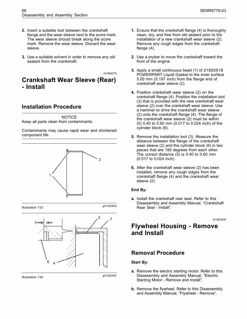
66 SENR9779-03Disassembly and Assembly Section
2. Insert a suitable tool between the crankshaftflange and the wear sleeve next to the score mark.The wear sleeve should break along the scoremark. Remove the wear sleeve. Discard the wearsleeve.
3. Use a suitable solvent in order to remove any oldsealant from the crankshaft.
i01964075
Crankshaft Wear Sleeve (Rear)- Install
Installation Procedure
NOTICEKeep all parts clean from contaminants.
Contaminants may cause rapid wear and shortenedcomponent life.
g01020643Illustration 133
g01020497Illustration 134
1. Ensure that the crankshaft flange (4) is thoroughlyclean, dry, and free from old sealant prior to theinstallation of a new crankshaft wear sleeve (2).Remove any rough edges from the crankshaftflange (4).
2. Use a prybar to move the crankshaft toward thefront of the engine.
3. Apply a small continuous bead (1) of 21820518POWERPART Liquid Gasket to the inner surface5.00 mm (0.197 inch) from the flange end ofcrankshaft wear sleeve (2).
4. Position crankshaft wear sleeve (2) on thecrankshaft flange (4). Position the installation tool(3) that is provided with the new crankshaft wearsleeve (2) over the crankshaft wear sleeve. Usea hammer to drive the crankshaft wear sleeve(2) onto the crankshaft flange (4). The flange ofthe crankshaft wear sleeve (2) must be within(5) 0.40 to 0.60 mm (0.017 to 0.024 inch) of thecylinder block (6).
5. Remove the installation tool (3). Measure thedistance between the flange of the crankshaftwear sleeve (2) and the cylinder block (6) in twoplaces that are 180 degrees from each other.The correct distance (5) is 0.40 to 0.60 mm(0.017 to 0.024 inch).
6. After the crankshaft wear sleeve (2) has beeninstalled, remove any rough edges from thecrankshaft flange (4) and the crankshaft wearsleeve (2).
End By:
a. Install the crankshaft rear seal. Refer to thisDisassembly and Assembly Manual, “CrankshaftRear Seal - Install”.
i01963628
Flywheel Housing - Removeand Install
Removal ProcedureStart By:
a. Remove the electric starting motor. Refer to thisDisassembly and Assembly Manual, “ElectricStarting Motor - Remove and Install”.
b. Remove the flywheel. Refer to this Disassemblyand Assembly Manual, “Flywheel - Remove”.
This document has been printed from SPI². Not for Resale

SENR9779-03 67Disassembly and Assembly Section
NOTICEKeep all parts clean from contaminants.
Contaminants may cause rapid wear and shortenedcomponent life.
NOTICECare must be taken to ensure that fluids are containedduring performance of inspection, maintenance, test-ing, adjusting and repair of the product. Be prepared tocollect the fluid with suitable containers before open-ing any compartment or disassembling any compo-nent containing fluids.
Dispose of all fluids according to local regulations andmandates.
g01020398Illustration 135
Note: The flywheel housing (2) is heavy. Use suitablelifting equipment to support the flywheel housing (2)while the setscrews (1) are being removed and whilethe flywheel housing is being removed.
1. Remove all of the setscrews (1) from the flywheelhousing (2).
2. Remove the flywheel housing (2). If necessary, hitthe flywheel housing with a soft faced hammer inorder to separate the flywheel housing (2) fromthe dowels (3) in the cylinder block.
Installation Procedure
NOTICEKeep all parts clean from contaminants.
Contaminants may cause rapid wear and shortenedcomponent life.
g01020405Illustration 136
1. Clean the rear face of the cylinder block and themating surface of the flywheel housing (2).
2. If a felt seal (4) is installed, replace the felt seal.Inspect the dowels (3) in the cylinder block thatalign the flywheel housing (2). Replace the dowels(3), if necessary.
Note: The flywheel housing (2) is heavy. Use suitablelifting equipment to support the flywheel housing (2)while the flywheel housing is being lifted and whilethe setscrews (1) are being installed.
3. Install the flywheel housing (2) onto the dowels (3)that are in the cylinder block.
4. Install all of the setscrews (1) that attach theflywheel housing (2) to the cylinder block.
Tighten the setscrews (1) to the following torque:
M10 “8.8” ............................. 44 N·m (33 lb ft)M10 “10.9” ........................... 63 N·m (46 lb ft)M12 “8.8” ............................. 75 N·m (55 lb ft)M12 “10.9” .......................... 115 N·m (85 lb ft)
5. Check the alignment of the flywheel housing (2)with the cylinder block. Refer to the Testing andAdjusting Manual, “Flywheel Housing - Inspect”.
End By:
a. Install the flywheel. Refer to this Disassembly andAssembly Manual, “Flywheel - Install”.
b. Install the electric starting motor. Refer to thisDisassembly and Assembly Manual, “ElectricStarting Motor - Remove and Install”.
This document has been printed from SPI². Not for Resale
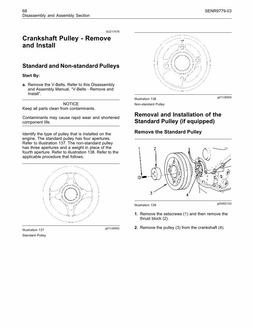
68 SENR9779-03Disassembly and Assembly Section
i02217476
Crankshaft Pulley - Removeand Install
Standard and Non-standard PulleysStart By:
a. Remove the V-Belts. Refer to this Disassemblyand Assembly Manual, “V-Belts - Remove andInstall”.
NOTICEKeep all parts clean from contaminants.
Contaminants may cause rapid wear and shortenedcomponent life.
Identify the type of pulley that is installed on theengine. The standard pulley has four apertures.Refer to illustration 137. The non-standard pulleyhas three apertures and a weight in place of thefourth aperture. Refer to illustration 138. Refer to theapplicable procedure that follows.
g01126952Illustration 137
Standard Pulley
g01126955Illustration 138Non-standard Pulley
Removal and Installation of theStandard Pulley (if equipped)
Remove the Standard Pulley
g00952102Illustration 139
1. Remove the setscrews (1) and then remove thethrust block (2).
2. Remove the pulley (3) from the crankshaft (4).
This document has been printed from SPI². Not for Resale

SENR9779-03 69Disassembly and Assembly Section
Install the Standard Pulley
g00952102Illustration 140
1. Clean the pulley (3) and clean the thrust block(2). Inspect the pulley (3) and the thrust block (2)for wear and for damage. If necessary, replaceany damaged component. Inspect the area onthe pulley that is normally in contact with thecrankshaft front seal. If there is excessive wearthen a wear sleeve can be installed. Refer to theDisassembly and Assembly Manual, “CrankshaftWear Sleeve (Front) - Remove and CrankshaftWear Sleeve (Rear) - Install” for further details.
2. Position the pulley (3) onto the crankshaft (4).
3. Lubricate the threads and the shoulder of thesetscrews (1) with clean engine oil. Position thethrust block (2) and install the setscrews (1).Tighten the setscrews evenly to a final torque of115 N·m (85 lb ft).
4. Tighten each of the setscrews (1) again to thesame torque in order to ensure that the setscrewsare still at the required torque.
Removal and Installation of theNon-standard Pulley (if equipped)There are two procedures for removal and installationof the non-standard pulley. One procedure is usedwhen the crankshaft is not replaced. The secondprocedure is used when the non-standard pulley isremoved prior to replacement of the crankshaft.
Remove the Non-standard Pulley whenthe Crankshaft is Not Replaced
g01127338Illustration 141
g01127411Illustration 142
1. Remove the setscrews (1) and then remove thethrust block (2).
2. Apply a mark on the front face of the crankshaft(4) that is aligned with the mark on the pulley (5).
3. Remove the pulley (3) from the crankshaft (4).
Install the Non-standard Pulley when theCrankshaft is Not Replaced
g01127338Illustration 143
This document has been printed from SPI². Not for Resale
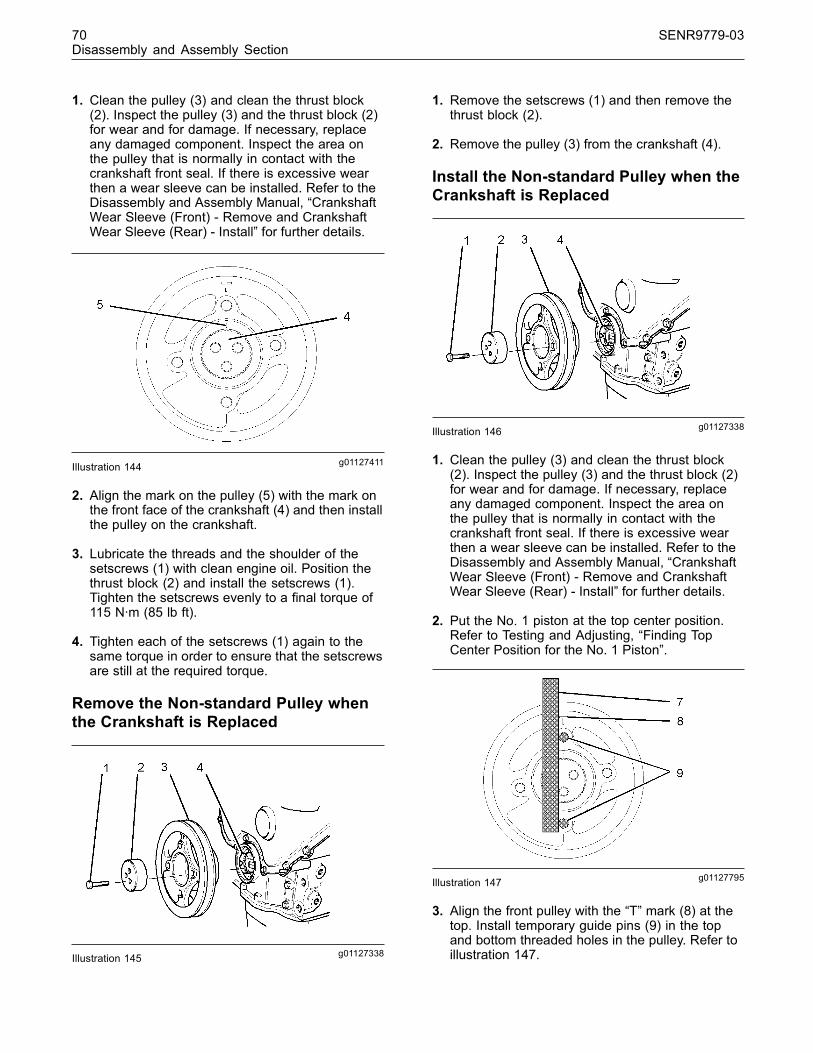
70 SENR9779-03Disassembly and Assembly Section
1. Clean the pulley (3) and clean the thrust block(2). Inspect the pulley (3) and the thrust block (2)for wear and for damage. If necessary, replaceany damaged component. Inspect the area onthe pulley that is normally in contact with thecrankshaft front seal. If there is excessive wearthen a wear sleeve can be installed. Refer to theDisassembly and Assembly Manual, “CrankshaftWear Sleeve (Front) - Remove and CrankshaftWear Sleeve (Rear) - Install” for further details.
g01127411Illustration 144
2. Align the mark on the pulley (5) with the mark onthe front face of the crankshaft (4) and then installthe pulley on the crankshaft.
3. Lubricate the threads and the shoulder of thesetscrews (1) with clean engine oil. Position thethrust block (2) and install the setscrews (1).Tighten the setscrews evenly to a final torque of115 N·m (85 lb ft).
4. Tighten each of the setscrews (1) again to thesame torque in order to ensure that the setscrewsare still at the required torque.
Remove the Non-standard Pulley whenthe Crankshaft is Replaced
g01127338Illustration 145
1. Remove the setscrews (1) and then remove thethrust block (2).
2. Remove the pulley (3) from the crankshaft (4).
Install the Non-standard Pulley when theCrankshaft is Replaced
g01127338Illustration 146
1. Clean the pulley (3) and clean the thrust block(2). Inspect the pulley (3) and the thrust block (2)for wear and for damage. If necessary, replaceany damaged component. Inspect the area onthe pulley that is normally in contact with thecrankshaft front seal. If there is excessive wearthen a wear sleeve can be installed. Refer to theDisassembly and Assembly Manual, “CrankshaftWear Sleeve (Front) - Remove and CrankshaftWear Sleeve (Rear) - Install” for further details.
2. Put the No. 1 piston at the top center position.Refer to Testing and Adjusting, “Finding TopCenter Position for the No. 1 Piston”.
g01127795Illustration 147
3. Align the front pulley with the “T” mark (8) at thetop. Install temporary guide pins (9) in the topand bottom threaded holes in the pulley. Refer toillustration 147.
This document has been printed from SPI². Not for Resale
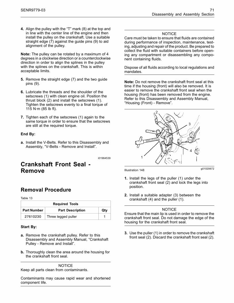
SENR9779-03 71Disassembly and Assembly Section
4. Align the pulley with the “T” mark (8) at the top andin line with the center line of the engine and theninstall the pulley on the crankshaft. Use a suitablestraight edge (7) against the guide pins (9) to aidalignment of the pulley.
Note: The pulley can be rotated by a maximum of 4degrees in a clockwise direction or a counterclockwisedirection in order to align the splines in the pulleywith the splines on the crankshaft. This is withinacceptable limits.
5. Remove the straight edge (7) and the two guidepins (9).
6. Lubricate the threads and the shoulder of thesetscrews (1) with clean engine oil. Position thethrust block (2) and install the setscrews (1).Tighten the setscrews evenly to a final torque of115 N·m (85 lb ft).
7. Tighten each of the setscrews (1) again to thesame torque in order to ensure that the setscrewsare still at the required torque.
End By:
a. Install the V-Belts. Refer to this Disassembly andAssembly, “V-Belts - Remove and Install”.
i01964539
Crankshaft Front Seal -Remove
Removal ProcedureTable 13
Required Tools
Part Number Part Description Qty
27610230 Three legged puller 1
Start By:
a. Remove the crankshaft pulley. Refer to thisDisassembly and Assembly Manual, “CrankshaftPulley - Remove and Install”.
b. Thoroughly clean the area around the housing forthe crankshaft front seal.
NOTICEKeep all parts clean from contaminants.
Contaminants may cause rapid wear and shortenedcomponent life.
NOTICECare must be taken to ensure that fluids are containedduring performance of inspection, maintenance, test-ing, adjusting and repair of the product. Be prepared tocollect the fluid with suitable containers before open-ing any compartment or disassembling any compo-nent containing fluids.
Dispose of all fluids according to local regulations andmandates.
Note: Do not remove the crankshaft front seal at thistime if the housing (front) will also be removed. It iseasier to remove the crankshaft front seal when thehousing (front) has been removed from the engine.Refer to this Disassembly and Assembly Manual,“Housing (Front) - Remove”.
g01020672Illustration 148
1. Install the legs of the puller (1) under thecrankshaft front seal (2) and lock the legs intoposition.
2. Install a suitable adapter (3) between thecrankshaft (4) and the puller (1).
NOTICEEnsure that the main lip is used in order to remove thecrankshaft front seal. Do not damage the edge of thehousing for the crankshaft front seal.
3. Use the puller (1) in order to remove the crankshaftfront seal (2). Discard the crankshaft front seal (2).
This document has been printed from SPI². Not for Resale

72 SENR9779-03Disassembly and Assembly Section
i01964540
Crankshaft Front Seal - Install
Installation ProcedureTable 14
Required Tools
PartNumber Part Description Qty
21825577 Crankshaft Front Seal Replacer 1
21825580 Fastener Plate 1
21825578 Pressure Plate 1
27610217 Adapter 1
NOTICEKeep all parts clean from contaminants.
Contaminants may cause rapid wear and shortenedcomponent life.
Note: This procedure assumes that the housing(front) is still on the engine. Do not follow thisprocedure if the housing (front) has been removedfrom the engine. Refer to this Disassembly andAssembly Manual, “Housing (Front) - Install” if thehousing (front) has been removed from the engine.
1. Clean the oil seal housing (8) and inspect the oilseal housing for damage. If necessary, replacethe housing (front). Refer to this Disassembly andAssembly Manual, “Housing (Front) - Remove andHousing (Front) - Install”.
2. Check the face on the pulley that contacts thecrankshaft front seal for wear. If necessary, repairthe crankshaft pulley. Refer to this Disassemblyand Assembly Manual, “Crankshaft Wear Sleeve(Front) - Remove and Crankshaft Wear Sleeve(Front) - Install” for further details.
g01020716Illustration 149
Note: A sleeve (5) is attached to the new crankshaftfront seal (6). Do not remove the sleeve (5) at thistime. Discard the new crankshaft front seal (6) if thesleeve (5) is not installed on the new crankshaft frontseal.
3. Install the 21825580 Fastener Plate (7) to thefront of the crankshaft.
4. Install the nut (1) and 21825578 Pressure Plate(2) onto the threaded bar (3).
Note: Do not lubricate the crankshaft front seal (6).Do not lubricate the oil seal housing (8).
5. Align the assembly of the sleeve (5) and thecrankshaft front seal (6) to the front of the oil sealhousing (8).
6. Install the 27610217 Adapter (4) onto the sleeve(5).
7. Install the pressure plate (2) onto the adapter (4)and tighten the threaded bar (3) onto the fastenerplate (7). Check the alignment of the assemblyand the crankshaft front seal (6) to the oil sealhousing (8).
8. Insert a suitable rod through the hole (9) in thethreaded bar (3) in order to prevent the threadedrod from turning as the nut (1) is tightened. Tightenthe nut (1) in order to push the crankshaft frontseal (6) into the oil seal housing (8). Continue totighten the nut (1) until contact is made with thebottom face of the oil seal housing (8).
9. Remove items (1), (2), (3), and (4).
10. Turn the sleeve (5) counterclockwise and pull thesleeve at the same time in order to remove thesleeve from the oil seal housing (8). Remove theadapter (7).
This document has been printed from SPI². Not for Resale
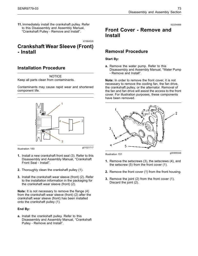
SENR9779-03 73Disassembly and Assembly Section
11. Immediately install the crankshaft pulley. Referto this Disassembly and Assembly Manual,“Crankshaft Pulley - Remove and Install”.
i01964526
Crankshaft Wear Sleeve (Front)- Install
Installation Procedure
NOTICEKeep all parts clean from contaminants.
Contaminants may cause rapid wear and shortenedcomponent life.
g01021717Illustration 150
1. Install a new crankshaft front seal (3). Refer to thisDisassembly and Assembly Manual, “CrankshaftFront Seal - Install”.
2. Thoroughly clean the crankshaft pulley (1).
3. Install the crankshaft wear sleeve (front) (2). Referto the installation information in the packaging forthe crankshaft wear sleeve (front) (2).
Note: It is not necessary to remove the flange (4)from the crankshaft wear sleeve (front) (2) after thecrankshaft wear sleeve (front) has been installedonto the crankshaft pulley (1).
End By:
a. Install the crankshaft pulley. Refer to thisDisassembly and Assembly Manual, “CrankshaftPulley - Remove and Install”.
i02254888
Front Cover - Remove andInstall
Removal ProcedureStart By:
a. Remove the water pump. Refer to thisDisassembly and Assembly Manual, “Water Pump- Remove and Install”.
Note: In order to remove the front cover, it is notnecessary to remove the cooling fan, the fan drive,the crankshaft pulley, or the alternator. Removal ofthe fan and fan drive will assist the access to the frontcover. For illustration purposes, these componentshave been removed.
g00955548Illustration 151
1. Remove the setscrews (3), the setscrews (4), andthe setscrew (5) from the front cover (1).
2. Remove the front cover (1) from the front housing.
3. Remove the joint (2) from the front cover (1).Discard the joint (2).
This document has been printed from SPI². Not for Resale

74 SENR9779-03Disassembly and Assembly Section
Installation Procedure
g00955548Illustration 152
g01020892Illustration 153
1. Thoroughly clean all the surfaces of the front cover(1) and clean the joint face of the housing (front).
2. Install two guide studs into the appropriate holes(6) within the housing (front).
3. Position the joint (2) onto the front cover (1).
Note: The joint is located by the three locatingdowels (7) on the front cover.
4. Position the front cover (1) and the joint (2) onthe front housing. Install setscrews (3) into holes(8). Install setscrew (5) into hole (9). Remove thetwo guide studs from the holes (6). Install theremainder of the setscrews (4). Tighten all of thesetscrews finger tight.
5. Loosely install the water pump. Refer to thisDisassembly and Assembly Manual, “Water Pump- Remove and Install”.
6. Tighten all of the setscrews (3, 4, and 5) for thefront cover (1) and tighten all of the setscrews forthe water pump to a torque of 22 N·m (16 lb ft).
End By:
a. If necessary, install the fan drive. Refer to thisDisassembly and Assembly, “Fan Drive - Removeand Install”.
b. If necessary, install the fan. Refer to thisDisassembly and Assembly Manual, “Fan -Remove and Install”.
i02217477
Gear Group (Front) - Remove
Removal ProcedureTable 15
Required Tools
Part Number Part Description Qty
27610211 Crankshaft timing pin 1
27610212 Camshaft timing pin 1
Start By:
a. Remove the front cover. Refer to this Disassemblyand Assembly Manual, “Front Cover - Removeand Install”.
NOTICEKeep all parts clean from contaminants.
Contaminants may cause rapid wear and shortenedcomponent life.
NOTICECare must be taken to ensure that fluids are containedduring performance of inspection, maintenance, test-ing, adjusting and repair of the product. Be prepared tocollect the fluid with suitable containers before open-ing any compartment or disassembling any compo-nent containing fluids.
Dispose of all fluids according to local regulations andmandates.
This document has been printed from SPI². Not for Resale

SENR9779-03 75Disassembly and Assembly Section
g01021972Illustration 154Typical example (Bosch drive gear)
g01021973Illustration 155
Typical example (Delphi fuel pump drive gear)
Note: Care must be taken in order to ensure thatthe fuel injection pump timing is not lost duringthe removal of the fuel injection pump and/or fuelinjection pump gear. Carefully follow the appropriateinstructions in order to remove the fuel injection pumpand/or fuel injection pump gear.
Note: If necessary, remove the glow plugs in orderto allow the crankshaft to rotate more freely. Refer tothis Disassembly and Assembly Manual, “Glow Plugs- Remove and Install”.
1. Rotate the crankshaft to top dead center. Referto the Testing and Adjusting Manual, “FindingTop Center for No. 1 Piston”. Apply handpressure to the fuel injection pump gear (1) in acounterclockwise direction in order to remove thebacklash (2) in the gears. Mark the orientation ofeach of the gears for installation purposes.
Note: Timing pins are used in order to time theengine at top dead center. The timing pins are a slipfit. Do not use excessive force to install the timingpins. Do not use the timing pins to lock the engineduring repairs.
2. Insert the 27610211 Crankshaft timing pin (3)through the housing (front) and into the web ofthe crankshaft. Insert the 27610212 Camshafttiming pin (4) through the camshaft gear (5) andinto the housing (front).
3. Remove the rocker shaft. Refer to thisDisassembly and Assembly Manual, “RockerShaft and Pushrod - Remove”.
Note: The fuel injection pump must be locked beforeproceeding further.
Note: The three cylinder engine can be equippedwith either the Delphi DP210 or the Delphi DPG fuelinjection pump.
Note: The four cylinder engine can be equippedwith the Delphi DP210, the Delphi DPA or the BoschEPVE fuel injection pump. The various types of fuelinjection pump have a different procedure for lockingthe fuel injection pump shaft.
g01022971Illustration 156
Four cylinder engine only
4. In order to lock the Bosch EPVE fuel injectionpump, loosen the locking screw (6) and removethe washer (7). Tighten the locking screw (6) to atorque of 31 N·m (23 lb ft).
g01022972Illustration 157
Three cylinder and four cylinder engines
This document has been printed from SPI². Not for Resale
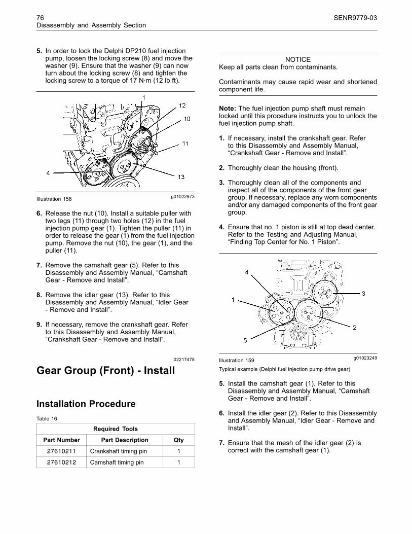
76 SENR9779-03Disassembly and Assembly Section
5. In order to lock the Delphi DP210 fuel injectionpump, loosen the locking screw (8) and move thewasher (9). Ensure that the washer (9) can nowturn about the locking screw (8) and tighten thelocking screw to a torque of 17 N·m (12 lb ft).
g01022973Illustration 158
6. Release the nut (10). Install a suitable puller withtwo legs (11) through two holes (12) in the fuelinjection pump gear (1). Tighten the puller (11) inorder to release the gear (1) from the fuel injectionpump. Remove the nut (10), the gear (1), and thepuller (11).
7. Remove the camshaft gear (5). Refer to thisDisassembly and Assembly Manual, “CamshaftGear - Remove and Install”.
8. Remove the idler gear (13). Refer to thisDisassembly and Assembly Manual, “Idler Gear- Remove and Install”.
9. If necessary, remove the crankshaft gear. Referto this Disassembly and Assembly Manual,“Crankshaft Gear - Remove and Install”.
i02217478
Gear Group (Front) - Install
Installation ProcedureTable 16
Required Tools
Part Number Part Description Qty
27610211 Crankshaft timing pin 1
27610212 Camshaft timing pin 1
NOTICEKeep all parts clean from contaminants.
Contaminants may cause rapid wear and shortenedcomponent life.
Note: The fuel injection pump shaft must remainlocked until this procedure instructs you to unlock thefuel injection pump shaft.
1. If necessary, install the crankshaft gear. Referto this Disassembly and Assembly Manual,“Crankshaft Gear - Remove and Install”.
2. Thoroughly clean the housing (front).
3. Thoroughly clean all of the components andinspect all of the components of the front geargroup. If necessary, replace any worn componentsand/or any damaged components of the front geargroup.
4. Ensure that no. 1 piston is still at top dead center.Refer to the Testing and Adjusting Manual,“Finding Top Center for No. 1 Piston”.
g01023249Illustration 159Typical example (Delphi fuel injection pump drive gear)
5. Install the camshaft gear (1). Refer to thisDisassembly and Assembly Manual, “CamshaftGear - Remove and Install”.
6. Install the idler gear (2). Refer to this Disassemblyand Assembly Manual, “Idler Gear - Remove andInstall”.
7. Ensure that the mesh of the idler gear (2) iscorrect with the camshaft gear (1).
This document has been printed from SPI². Not for Resale

SENR9779-03 77Disassembly and Assembly Section
g01023250Illustration 160Typical example (Bosch fuel injection pump drive gear)
8. Install the fuel injection pump gear (3) onto thefuel injection pump shaft. Ensure that the meshof the fuel injection pump gear (3) is correct withthe idler gear (2). Install the washer and the nut(6) finger tight.
9. Apply hand pressure to the fuel injection pumpgear (3) in a counterclockwise direction in order toremove the backlash in the gears (1), (2), and (3).Tighten the nut (6) to a torque of 24 N·m (18 lb ft).
10.Ensure that all of the timing marks on the gears(1), (2), and (3) are in alignment.
Note: The three cylinder engine can be equippedwith either the Delphi DP210 or the Delphi DPG fuelinjection pump.
Note: The four cylinder engine can be equippedwith the Delphi DP210, the Delphi DPA or the BoschEPVE fuel injection pump. The various types of fuelinjection pump have a different procedure for lockingthe fuel injection pump shaft.
g01023252Illustration 161Four cylinder engine only
11. Release the locked fuel injection pump shaft.In order to unlock the Bosch EPVE fuel injectionpump shaft, loosen the locking screw (7) andinstall the washer (8). Tighten the locking screw (7)onto the washer (8) to a torque of 12 N·m (9 lb ft).
g01023253Illustration 162Three cylinder and four cylinder engines
12. In order to unlock the Delphi DP210 fuel injectionpump shaft, loosen the locking screw (9) andmove the washer (10). Tighten the locking screw(9) onto the washer (10) to a torque of 12 N·m(9 lb ft).
13. Tighten the nut (6) to an increased torque of90 N·m (66 lb ft). Refer to illustration 160.
14.Remove the timing pins (4) and (5). Refer toillustration 159.
15.Check the backlash value for the fuel injectionpump gear (3). Refer to the Specifications Manual,“Gear Group (Front)” for further information.
16.Check the end play of the idler gear (2). Referto this Disassembly and Assembly Manual, “IdlerGear - Remove and Install” and refer to theSpecifications Manual, “Gear Group (Front)” forfurther information.
17.Check the backlash value for the idler gear (2).Refer to this Disassembly and Assembly Manual,“Idler Gear - Remove and Install” and refer to theSpecifications Manual, “Gear Group (Front)” forfurther information.
18.Check the end play of the camshaft gear (1).Refer to this Disassembly and Assembly Manual,“Camshaft Gear - Remove and Install”.
19.Check the backlash value for the camshaft gear(1). Refer to this Disassembly and AssemblyManual, “Camshaft Gear - Remove and Install”and refer to the Specifications Manual, “GearGroup (Front)” for further information.
20. Lightly lubricate each gear with clean enginelubricating oil.
This document has been printed from SPI². Not for Resale

78 SENR9779-03Disassembly and Assembly Section
End By:
a. Install the front cover. Refer to Disassembly andAssembly, “Front Cover - Remove and Install”.
b. Install the glow plugs. Refer to this Disassemblyand Assembly Manual, “Glow Plugs - Removeand Install”.
c. Install the rocker shaft. Refer to this Disassemblyand Assembly Manual, “Rockershaft and Pushrod- Install”.
i02217480
Idler Gear - Remove and Install
Removal ProcedureTable 17
Required Tools
Part Number Part Name Qty
27610212 Camshaft (Timing Pin) 1
27610211 Crankshaft (Timing Pin) 1
Start By:
a. Remove the front cover if the front cover hasnot previously been removed. Refer to thisDisassembly and Assembly Manual, “Front Cover- Remove and Install”.
NOTICEKeep all parts clean from contaminants.
Contaminants may cause rapid wear and shortenedcomponent life.
NOTICECare must be taken to ensure that fluids are containedduring performance of inspection, maintenance, test-ing, adjusting and repair of the product. Be prepared tocollect the fluid with suitable containers before open-ing any compartment or disassembling any compo-nent containing fluids.
Dispose of all fluids according to local regulations andmandates.
Note: There are two types of idler gear that maybe installed on these engines. The standard idlergear is supported on the hub by two bushes. Theheavy-duty idler gear is supported on the hub by tworoller bearings.
Note: If necessary, remove the glow plugs in orderto allow the crankshaft to rotate more freely. Refer tothis Disassembly and Assembly Manual, “Glow Plugs- Remove and Install”.
Note: The three cylinder engine can be equippedwith either the Delphi DP210 or the Delphi DPG fuelinjection pump.
Note: The four cylinder engine can be equippedwith the Delphi DP210, the Delphi DPA or the BoschEPVE fuel injection pump. The various types of fuelinjection pump have a different procedure for lockingthe fuel injection pump shaft.
g01021972Illustration 163Typical example (Bosch fuel injection pump drive gear)
g01021973Illustration 164
Typical example (Delphi fuel injection pump drive gear)
1. Ensure that the No. 1 cylinder is at top deadcenter on the compression stroke. Refer to theTesting and Adjusting Manual, “Finding TopCenter Position for No. 1 Piston”. Apply handpressure to the fuel injection pump gear (1) ina counterclockwise direction in order to removebacklash (2) in the gears. Mark the orientation ofeach of the gears for installation purposes.
This document has been printed from SPI². Not for Resale

SENR9779-03 79Disassembly and Assembly Section
Note: Timing pins are used in order to time theengine at top dead center. The timing pins are a slipfit. Do not use excessive force to install the timingpins. Do not use the timing pins to lock the engineduring repairs.
2. Insert the 27610211 Crankshaft timing pin (3)through the housing (front) and into the web ofthe crankshaft if the timing pin has not previouslybeen installed. Insert the 27610212 Camshafttiming pin (4) through the camshaft gear (5) andinto the housing (front) if the timing pin was notpreviously installed.
3. Remove the rocker shaft if the rocker shaft wasnot previously removed. Refer to this Disassemblyand Assembly Manual, “Rocker Shaft and Pushrod- Remove”.
4. Remove the fuel injection pump gear (1) if thegear has not previously been removed. Refer tothis Disassembly and Assembly Manual, “GearGroup (Front) - Remove”.
g01038900Illustration 165
5. Remove the three setscrews (6) from the idlergear (8). Remove the plate (7) from the idler gear(8).
g01023843Illustration 166
g01038902Illustration 167
g01023845Illustration 168Standard idler gear assembly
6. Remove the assembly (9) of the idler gear (8) andthe hub from the recess (10) in the cylinder block.The assembly (9) must be lifted over the housingfor the crankshaft front seal (11) as the assemblyis moved forward.
7. Disassemble the assembly (9) of the idler gear (8)and the hub. In order to disassemble the standardassembly (9), slide the hub (12) out of the idlergear (8). Inspect the bushes (13) in the idler gear(8) for wear and/or damage. If necessary, removethe bushes (13) from each side of the idler gear(8).
This document has been printed from SPI². Not for Resale

80 SENR9779-03Disassembly and Assembly Section
g01023942Illustration 169Heavy-duty idler gear assembly
8. In order to disassemble the heavy-duty idler gear,press the hub (12) out of the bearing assembly(16). Remove the circlip (14) and the thrustwasher (15) from the idler gear (8). If the bearingassembly (16) is worn and/or damaged, slide thebearing assembly out of the idler gear (8). Discardthe bearing assembly (16). Remove the circlip(17) and the thrust washer (18).
Installation ProcedureTable 18
Required Tools
27610212 Timing Pin (Camshaft) 1
27610211 Timing Pin (Crankshaft) 1
NOTICEKeep all parts clean from contaminants.
Contaminants may cause rapid wear and shortenedcomponent life.
1. Clean all of the components and inspect all of thecomponents that were removed in the previousprocedure. If necessary, replace any worncomponent and/or any damaged component.
g01024162Illustration 170Typical example (Delphi fuel injection pump drive gear)
Note: Timing pins are used in order to time theengine at top dead center. The timing pins are a slipfit. Do not use excessive force to install the timingpins. Do not use the timing pins to lock the engineduring repairs.
2. Ensure that the No. 1 cylinder is still at top deadcenter on the compression stroke. If necessary,refer to the Testing and Adjusting Manual, “FindingTop Center Position for No. 1 Piston”. Ensure thatthe timing pin (3) for the crankshaft is installed andthat the timing pin (4) for the camshaft is installed.
g01024165Illustration 171
Note: Ensure that the marks (19) on the idler gear(8) face toward the front of the engine when theassembly (9) of the idler gear and the hub is beingassembled.
This document has been printed from SPI². Not for Resale

SENR9779-03 81Disassembly and Assembly Section
g01024432Illustration 172Standard idler gear assembly
3. Assemble the assembly (9) of the idler gearand the hub. In order to assemble the standardassembly, press new bushes (13) into the idlergear (8) if the bushes were previously removed.Lubricate the hub (12 ) with clean enginelubricating oil. Slide the hub (12) into the idler gear(8). Ensure that the oil hole (20) is to the top of thehub (12) and ensure that the marks (19) are to thefront of the idler gear (8).
g01023942Illustration 173
Heavy-duty idler gear assembly
Note: The new bearing assembly (16) is supplied witha protective sleeve. Do not remove this protectivesleeve. The protective sleeve prevents the rollersfrom falling out of the roller bearings.
4. In order to assemble the heavy-duty idler gear,install the circlip (17) into the back face of the idlergear (8). Place the back face of the idler gear(8) onto a clean, flat surface. Insert the thrustwasher (18) through the idler gear (8) and ontothe circlip (17). Ensure that the flange face of thebearing assembly (16) is toward the bottom andthat the protective sleeve is still in place. Insertthe new bearing assembly (16) into the idler gear(8). Push the new bearing assembly (16) into theidler gear (8) until the bearing assembly comesinto contact with the thrust washer (18). As thebearing assembly (16) is pushed into the idlergear (8) the protective sleeve will remain on thetop face of the idler gear. Discard the protectivesleeve. Install the thrust washer (15) and installthe circlip (14). Lightly lubricate the hub (12) withclean engine lubricating oil. Press the hub (12)into the idler gear (8).
g01023843Illustration 174
g01038902Illustration 175
This document has been printed from SPI². Not for Resale

82 SENR9779-03Disassembly and Assembly Section
g01021973Illustration 176
5. Lift the assembly (9) of the idler gear and thehub over the housing for the crankshaft front seal(11) and insert the hub into the recess (10) in thecylinder block.
Note: Ensure that the oil hole (20) is to the top ofthe hub (12).
Note: Ensure that the marks (19) on the idler gearassembly (9) align with the marks on the camshaftgear and with the crankshaft gear. Refer to theillustration 171.
6. Align the holes in the plate (7) with the holes inthe hub (12). Insert the setscrews (6) through theplate (7) and into the hub (12).
7. Evenly tighten the setscrews (6) to a torque of44 N·m (32 lb ft).
g00944081Illustration 177
8. Check the end play for the idler gear. Refer tothe illustration 177 and refer to the SpecificationsManual, “Gear Group (Front)” for more information.
g00944084Illustration 178
9. Check the backlash between the idler gear andthe camshaft gear. Refer to the illustration 178 andrefer to the Specifications Manual, “Gear Group(Front)” for more information.
10.Check the backlash between the idler gear andthe crankshaft gear. Refer to the SpecificationsManual, “Gear Group (Front)” for more information.
Note: The three cylinder engine can be equippedwith either the Delphi DP210 or the Delphi DPG fuelinjection pump.
Note: The four cylinder engine can be equippedwith the Delphi DP210, the Delphi DPA or the BoschEPVE fuel injection pump. The various types of fuelinjection pump have a different procedure for lockingthe fuel injection pump shaft.
11. Install the fuel injection pump gear. Refer to thisDisassembly and Assembly Manual, “Gear Group(Front) - Install”.
12.Remove the timing pin for the crankshaft (3) andremove the timing pin for the camshaft (4).
13. Lightly lubricate all of the gears with clean enginelubricating oil.
End By:
a. Install the rocker shaft. Refer to this Disassemblyand Assembly Manual, “Rocker Shaft and Pushrod- Install”.
b. Install the glow plugs if the glow plugs werepreviously removed. Refer to this Disassemblyand Assembly Manual, “Glow Plugs - remove andInstall”.
c. Install the front cover. Refer to this Disassemblyand Assembly Manual, “Front Cover - Removeand Install”.
This document has been printed from SPI². Not for Resale

SENR9779-03 83Disassembly and Assembly Section
i01964553
Housing (Front) - Remove
Removal ProcedureStart By:
a. Drain the coolant into a suitable container forstorage or disposal.
b. Remove the fan drive. Refer to this Disassemblyand Assembly Manual, “Fan Drive - Remove andInstall”.
c. If necessary, remove the alternator. Refer to thisDisassembly and Assembly Manual, “Alternator- Remove”.
d. Remove the fuel injection pump. Refer to theappropriate fuel injection pump within thisDisassembly and Assembly Manual, “FuelInjection Pump - Remove”.
e. Remove the engine oil pan. Refer to thisDisassembly and Assembly Manual, “Engine OilPan - Remove and Install”.
f. Remove the gear group (front). Refer to thisDisassembly and Assembly Manual, “Gear Group(Front) - Remove”.
NOTICEKeep all parts clean from contaminants.
Contaminants may cause rapid wear and shortenedcomponent life.
NOTICECare must be taken to ensure that fluids are containedduring performance of inspection, maintenance, test-ing, adjusting and repair of the product. Be prepared tocollect the fluid with suitable containers before open-ing any compartment or disassembling any compo-nent containing fluids.
Dispose of all fluids according to local regulations andmandates.
g00995185Illustration 179
1. Remove the setscrews (1). Remove the bypasstube (2) from the cylinder head. Remove theO-rings from the bypass tube (2). Discard theO-rings.
g01024469Illustration 180
2. Remove the setscrews (3) and the setscrews (4)that fasten the front housing (5) to the cylinderblock.
3. Remove the front housing (5). Remove the joint (6)from the cylinder block and the front housing (5).
4. Remove the joint (7) from the back side of thefront housing (5).
g01024472Illustration 181
This document has been printed from SPI². Not for Resale
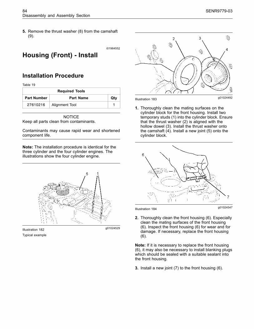
84 SENR9779-03Disassembly and Assembly Section
5. Remove the thrust washer (8) from the camshaft(9).
i01964552
Housing (Front) - Install
Installation ProcedureTable 19
Required Tools
Part Number Part Name Qty
27610216 Alignment Tool 1
NOTICEKeep all parts clean from contaminants.
Contaminants may cause rapid wear and shortenedcomponent life.
Note: The installation procedure is identical for thethree cylinder and the four cylinder engines. Theillustrations show the four cylinder engine.
g01024529Illustration 182Typical example
g01024492Illustration 183
1. Thoroughly clean the mating surfaces on thecylinder block for the front housing. Install twotemporary studs (1) into the cylinder block. Ensurethat the thrust washer (2) is aligned with thehollow dowel (3). Install the thrust washer ontothe camshaft (4). Install a new joint (5) onto thecylinder block.
g01024547Illustration 184
2. Thoroughly clean the front housing (6). Especiallyclean the mating surfaces of the front housing(6). Inspect the front housing (6) for wear and fordamage. If necessary, replace the front housing(6).
Note: If it is necessary to replace the front housing(6), it may also be necessary to install blanking plugswhich should be sealed with a suitable sealant intothe front housing.
3. Install a new joint (7) to the front housing (6).
This document has been printed from SPI². Not for Resale
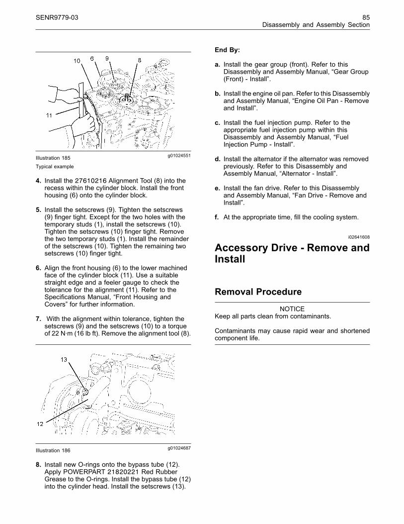
SENR9779-03 85Disassembly and Assembly Section
g01024551Illustration 185Typical example
4. Install the 27610216 Alignment Tool (8) into therecess within the cylinder block. Install the fronthousing (6) onto the cylinder block.
5. Install the setscrews (9). Tighten the setscrews(9) finger tight. Except for the two holes with thetemporary studs (1), install the setscrews (10).Tighten the setscrews (10) finger tight. Removethe two temporary studs (1). Install the remainderof the setscrews (10). Tighten the remaining twosetscrews (10) finger tight.
6. Align the front housing (6) to the lower machinedface of the cylinder block (11). Use a suitablestraight edge and a feeler gauge to check thetolerance for the alignment (11). Refer to theSpecifications Manual, “Front Housing andCovers” for further information.
7. With the alignment within tolerance, tighten thesetscrews (9) and the setscrews (10) to a torqueof 22 N·m (16 lb ft). Remove the alignment tool (8).
g01024687Illustration 186
8. Install new O-rings onto the bypass tube (12).Apply POWERPART 21820221 Red RubberGrease to the O-rings. Install the bypass tube (12)into the cylinder head. Install the setscrews (13).
End By:
a. Install the gear group (front). Refer to thisDisassembly and Assembly Manual, “Gear Group(Front) - Install”.
b. Install the engine oil pan. Refer to this Disassemblyand Assembly Manual, “Engine Oil Pan - Removeand Install”.
c. Install the fuel injection pump. Refer to theappropriate fuel injection pump within thisDisassembly and Assembly Manual, “FuelInjection Pump - Install”.
d. Install the alternator if the alternator was removedpreviously. Refer to this Disassembly andAssembly Manual, “Alternator - Install”.
e. Install the fan drive. Refer to this Disassemblyand Assembly Manual, “Fan Drive - Remove andInstall”.
f. At the appropriate time, fill the cooling system.
i02641608
Accessory Drive - Remove andInstall
Removal Procedure
NOTICEKeep all parts clean from contaminants.
Contaminants may cause rapid wear and shortenedcomponent life.
This document has been printed from SPI². Not for Resale

86 SENR9779-03Disassembly and Assembly Section
g01004414Illustration 187
1. Remove the setscrews (1) and the front cover (2).
2. Remove the Allen head screws (3) and (4).Remove the accessory drive assembly from therear face of the front housing (6).
3. Remove the circlip (5).
4. Place the flange of the front housing (6) onto asuitable support. Press the assembly of the gear(7) and the bearings (8 and 9) out of the fronthousing (6). Use a suitable puller in order toremove the bearings (8 and 9) from the gear (7).
5. Remove the O-ring (10) from the front housing (6)and discard the O-ring.
Installation Procedure
NOTICEKeep all parts clean from contaminants.
Contaminants may cause rapid wear and shortenedcomponent life.
g01004414Illustration 188
1. Inspect the condition of the teeth and the splinesof the gear (7), the bearings (8 and 9), the circlip(5), and the groove for the circlip in the fronthousing (6) for wear and for damage. Replace anyworn component or any damaged component.
g01004637Illustration 189
2. Apply a small continuous bead (11) of 21820603POWERPART Retainer (oil tolerant) to the outersurface of the bearing (9). Place the front flangeof the front housing (6) onto a suitable support.Press on the outer race of the bearing (9) until thebearing is against the front face of the recess forthe bearing in the front housing (6). Remove anyexcess sealant.
3. Apply a small continuous bead (12) of 21820603POWERPART Retainer (oil tolerant) to the innersurface of the bearing (9). Place the front face ofthe inner race of the bearing (9) onto a suitablesupport. Press the smaller shaft of the gear (7)into the bearing (9) until the shoulder of the gear isagainst the bearing. Remove any excess sealant.
This document has been printed from SPI². Not for Resale

SENR9779-03 87Disassembly and Assembly Section
4. Apply a small continuous bead (14) of 21820603POWERPART Retainer (oil tolerant) to theouter surface of the bearing (8). Apply a smallcontinuous bead (13) of 21820603 POWERPARTRetainer (oil tolerant) to the inner surface of thebearing (8). Ensure that the front face of the innerrace of the bearing (9) is still on a suitable support.Press the bearing (8) onto the larger shaft ofthe gear (7) until the bearing (9) is against theshoulder of the gear. Remove any excess sealant.
5. Install the circlip (5) into the groove in the fronthousing (6). Ensure that the circlip (5) is correctlypositioned in the groove.
g00946787Illustration 190Typical Example
6. Refer to the illustration 190 and check thebacklash between the idler gear and gear (7). Thebacklash should be within 0.11 mm (0.004 inch) to0.17 mm (0.007 inch).
7. Lightly lubricate a new O-ring (10) with 21820221POWERPART Red Rubber Grease and installthe O-ring into the recess in the front housing (6).Lightly lubricate the bearing (8), the bearing (9),and the gear (7) with clean engine lubricating oil.
8. By using the Allen head screws (3 and 4), installthe assembly of the accessory drive to the rearof the front housing (6). Torque the Allen headscrews to a torque of 22 N·m (16 lb ft).
9. By using the setscrews (1), install the front cover(2). Refer to this Disassembly and AssemblyManual, “Front Cover - Remove and Install.”.
i02217688
Crankcase Breather - Removeand Install
Removal Procedure for theDiaphragm ValveNote: All naturally aspirated three cylinder and fourcylinder engines in the 1100 Series except for modelsDJ and RR are equipped with a closed breathersystem. A closed breather system is optional forturbocharged three cylinder and four cylinder enginesin the 1100 Series.
Note: 1103 engines, models DJ and DK that areequipped with a open crankcase breather do not havea diaphragm valve in the valve mechanism cover.
Note: 1103 engines, models DC, DD, DF, DG andall 1104 engines that are equipped with a closedbreather system have a diaphragm valve in the valvemechanism cover.
g01122584Illustration 191
1103 engine, models DJ and DK
This document has been printed from SPI². Not for Resale

88 SENR9779-03Disassembly and Assembly Section
g01122835Illustration 192
1103 engine, models DC, DD, DF and DG
g01122836Illustration 1931104 engine
1. Refer to the appropriate illustration 191, 192 or193. Loosen the hose clamp (7) and release thehose from the connector (9).
2. Remove the fasteners (6) and remove theconnector (9) from the cylinder head and from thevalve mechanism cover (5). Remove the O-ring(10) from the connector (9). Discard the O-ring(10). Remove the joint (8). Discard the joint (8).
3. Remove the plastic cover (1) from the valvemechanism cover (5).
Personal injury can result from parts and/or cov-ers under spring pressure.
Spring force will be released when covers are re-moved.
Be prepared to hold spring loaded covers as thebolts are loosened.
4. Remove the screws (2). Remove the plate (3).
5. If equipped, remove the seal ring (4). Refer toillustration 191.
6. If equipped, remove the diaphragm (4) and the cap(13). Remove the spring (12). Refer to illustration192 or 193.
7. If the recess (11) for the assembly of thediaphragm valve needs to be cleaned, removethe valve mechanism cover (5). Refer to thisDisassembly and Assembly Manual, “ValveMechanism Cover - Remove and Install”. Ifnecessary, thoroughly clean the valve mechanismcover (5) and especially clean the recess (11).
Installation Procedure for theDiaphragm ValveNote: 1103 engines, models DJ and DK that areequipped with a closed breather system do not havea diaphragm valve in the valve mechanism cover.
Note: 1103 engines, models DC, DD, DF, DG andall 1104 engines that are equipped with a closedbreather system have a diaphragm valve in the valvemechanism cover.
This document has been printed from SPI². Not for Resale

SENR9779-03 89Disassembly and Assembly Section
g01122584Illustration 194
1103 engine, models DJ and DK
g01122835Illustration 1951103 engine, models DC, DD, DF and DG
g01122836Illustration 196
1104 engine
1. Refer to the appropriate illustration 194, 195or 196. Thoroughly clean all of the previouslyremoved components. Inspect all of thecomponents for wear and for damage. Especiallycheck the condition of the hose for the connector(9) and the diaphragm or the seal ring (4) fordamage. Replace any component that is wornand/or damaged.
2. If the valve mechanism cover (5) was removed,install the valve mechanism cover. Refer tothis Disassembly and Assembly Manual, “ValveMechanism Cover - Remove and Install”.
3. If equipped, install the seal ring (4) in the recess(11) in the valve mechanism cover (5).
Improper assembly of parts that are spring loadedcan cause bodily injury.
To prevent possible injury, follow the establishedassembly procedure and wear protective equip-ment.
4. If equipped, install the spring (12), the cap (13),and the diaphragm (4) into the recess (11) in thevalve mechanism cover (5).
5. If equipped, ensure that the two domes on theplate (3) are uppermost and ensure that the offsethole is toward the connector (9) of the valvemechanism cover (5). Install the plate (3). Installthe screws (2). Tighten the screws (2) to a torqueof 1.3 N·m (11.5 lb in).
This document has been printed from SPI². Not for Resale

90 SENR9779-03Disassembly and Assembly Section
6. Push the plastic cover (1) onto the valvemechanism cover (5).
7. Install a new O-ring (10) onto the connector (9).
8. Install a new joint (8) to the connector (9). Installthe connector (9) into the valve mechanism cover(5) and onto the cylinder head.
9. Install the fasteners (6). Tighten the fasteners (6)to a torque of 9 N·m (80 lb in).
10. Install the hose onto the connector (9). Ensurethat the hose is clear of all hot surfaces, clearof all components that move, and clear of allcomponents that vibrate when the engine isoperating. Tighten the hose clamp (7) to a torqueof 5 N·m (44 lb in).
i01947656
Valve Mechanism Cover -Remove and Install
Removal ProcedureStart By:
a. Remove the heat shields, if equipped.
b. Remove the cover for the fuel injectors. Refer tothis Disassembly and Assembly Manual, “FuelInjector Cover - Remove and Install”.
NOTICEKeep all parts clean from contaminants.
Contaminants may cause rapid wear and shortenedcomponent life.
NOTICECare must be taken to ensure that fluids are containedduring performance of inspection, maintenance, test-ing, adjusting and repair of the product. Be prepared tocollect the fluid with suitable containers before open-ing any compartment or disassembling any compo-nent containing fluids.
Dispose of all fluids according to local regulations andmandates.
Note: The removal procedure is identical for thethree cylinder and the four cylinder engines. Theillustration shows the four cylinder engine.
g00951080Illustration 197Typical example
1. Remove the breather tube (3) from the valvemechanism cover (1). Refer to this Disassemblyand Assembly Manual, “Crankcase Breather -Remove and Install”.
2. Remove the fasteners (2). Remove the valvemechanism cover (1). Remove the joint for thevalve mechanism cover and discard the joint.
Installation ProcedureNote: The installation procedure is identical for thethree cylinder and the four cylinder engines. Onlythe sequence for tightening the fasteners for thevalve mechanism cover is different. Refer to theappropriate illustration for further information.
g00951080Illustration 198Typical example
1. Thoroughly clean the valve mechanism cover (1).Ensure that the groove for the joint for the valvemechanism cover (1) is clean and dry. Ensurethat the mating face on the cylinder head is cleanand dry.
This document has been printed from SPI². Not for Resale
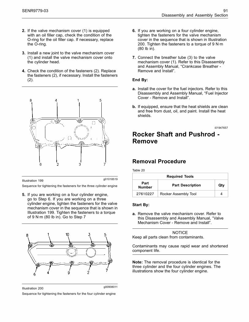
SENR9779-03 91Disassembly and Assembly Section
2. If the valve mechanism cover (1) is equippedwith an oil filler cap, check the condition of theO-ring for the oil filler cap. If necessary, replacethe O-ring.
3. Install a new joint to the valve mechanism cover(1) and install the valve mechanism cover ontothe cylinder head.
4. Check the condition of the fasteners (2). Replacethe fasteners (2), if necessary. Install the fasteners(2).
g01018519Illustration 199Sequence for tightening the fasteners for the three cylinder engine
5. If you are working on a four cylinder engine,go to Step 6. If you are working on a threecylinder engine, tighten the fasteners for the valvemechanism cover in the sequence that is shown inIllustration 199. Tighten the fasteners to a torqueof 9 N·m (80 lb in). Go to Step 7
g00908011Illustration 200
Sequence for tightening the fasteners for the four cylinder engine
6. If you are working on a four cylinder engine,tighten the fasteners for the valve mechanismcover in the sequence that is shown in Illustration200. Tighten the fasteners to a torque of 9 N·m(80 lb in).
7. Connect the breather tube (3) to the valvemechanism cover (1). Refer to this Disassemblyand Assembly Manual, “Crankcase Breather -Remove and Install”.
End By:
a. Install the cover for the fuel injectors. Refer to thisDisassembly and Assembly Manual, “Fuel InjectorCover - Remove and Install”.
b. If equipped, ensure that the heat shields are cleanand free from dust, oil, and paint. Install the heatshields.
i01947657
Rocker Shaft and Pushrod -Remove
Removal ProcedureTable 20
Required Tools
PartNumber Part Description Qty
27610227 Rocker Assembly Tool 4
Start By:
a. Remove the valve mechanism cover. Refer tothis Disassembly and Assembly Manual, “ValveMechanism Cover - Remove and Install”.
NOTICEKeep all parts clean from contaminants.
Contaminants may cause rapid wear and shortenedcomponent life.
Note: The removal procedure is identical for thethree cylinder and the four cylinder engines. Theillustrations show the four cylinder engine.
This document has been printed from SPI². Not for Resale
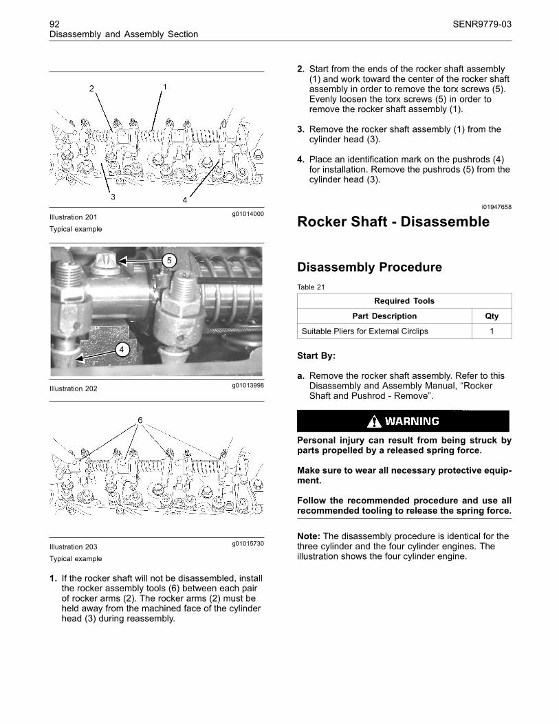
92 SENR9779-03Disassembly and Assembly Section
g01014000Illustration 201Typical example
g01013998Illustration 202
g01015730Illustration 203Typical example
1. If the rocker shaft will not be disassembled, installthe rocker assembly tools (6) between each pairof rocker arms (2). The rocker arms (2) must beheld away from the machined face of the cylinderhead (3) during reassembly.
2. Start from the ends of the rocker shaft assembly(1) and work toward the center of the rocker shaftassembly in order to remove the torx screws (5).Evenly loosen the torx screws (5) in order toremove the rocker shaft assembly (1).
3. Remove the rocker shaft assembly (1) from thecylinder head (3).
4. Place an identification mark on the pushrods (4)for installation. Remove the pushrods (5) from thecylinder head (3).
i01947658
Rocker Shaft - Disassemble
Disassembly ProcedureTable 21
Required Tools
Part Description Qty
Suitable Pliers for External Circlips 1
Start By:
a. Remove the rocker shaft assembly. Refer to thisDisassembly and Assembly Manual, “RockerShaft and Pushrod - Remove”.
Personal injury can result from being struck byparts propelled by a released spring force.
Make sure to wear all necessary protective equip-ment.
Follow the recommended procedure and use allrecommended tooling to release the spring force.
Note: The disassembly procedure is identical for thethree cylinder and the four cylinder engines. Theillustration shows the four cylinder engine.
This document has been printed from SPI². Not for Resale

SENR9779-03 93Disassembly and Assembly Section
g01014249Illustration 204Typical example
1. Remove the circlip (1) and remove the washer (2)from both ends of the rocker shaft assembly.
Note: The rocker shaft (6) is not symmetrical as thereis a machined flat (7) toward one end of the shaft.
2. Place an identification mark on each of thecomponents for installation. Ensure that you notethe component’s relationship to the machined flat(7).
3. Remove the rocker arm assembly (3) for the inletvalve from the rocker shaft (6). Remove the rockerarm assembly (4) for the exhaust valve from therocker shaft (6).
4. Remove the spring (5) from the rocker shaft (6).
5. Repeat Step 3 and Step 4 in order to completelydisassemble the rocker shaft assembly.
i01947659
Rocker Shaft - Assemble
Assembly ProcedureTable 22
Required Tools
Part Description Qty
Suitable Pliers for External Circlips 1
Note: The assembly procedure is identical for thethree cylinder and the four cylinder engines. Theillustration shows the four cylinder engine.
g01014249Illustration 205Typical example
1. Clean all of the components and inspect all ofthe components. Inspect the grooves for thecirclips (1) and ensure that all of the oil holesin the rocker shaft (6) and in the rocker arms(3 and 4) are not plugged before you begin theassembly procedure. If necessary, replace anyworn components and any damaged components.
2. Check the clearance between the rocker shaft (6)and the bushing of every rocker arm (3 and 4).Refer to the Specifications Manual, “Rocker Shaft”or further information. If necessary, replace anyworn components.
3. Lubricate all of the components with clean engineoil before assembly.
Note: Ensure that the machined flat (7) on the rockershaft (6) is facing upward.
4. Install a circlip (1) onto the end of the rocker shaft(6) that is closest to the machined flat (7). Install awasher (2) onto the rocker shaft (6).
5. Install the rocker arm assembly (3) for the inletvalve onto the rocker shaft (6). Install the rockerarm assembly (4) for the exhaust valve onto therocker shaft (6).
6. Install the spring (5) onto the rocker shaft (6).
7. Repeat Step 5 and Step 6 in order to assemblethe rocker shaft assembly.
Improper assembly of parts that are spring loadedcan cause bodily injury.
To prevent possible injury, follow the establishedassembly procedure and wear protective equip-ment.
This document has been printed from SPI². Not for Resale

94 SENR9779-03Disassembly and Assembly Section
8. Install the remaining washer (2) and the remainingcirclip (1) onto the rocker shaft (6).
End By:
a. Install the rocker shaft assembly. Refer to thisDisassembly and Assembly Manual, “RockerShaft and Pushrod - Install”.
i01947661
Rocker Shaft and Pushrod -Install
Installation ProcedureTable 23
Required Tools
PartNumber Part Description Qty
27610227 Rocker Assembly Tool 4
NOTICEKeep all parts clean from contaminants.
Contaminants may cause rapid wear and shortenedcomponent life.
Note: The installation procedure is identical for thethree cylinder and the four cylinder engines. Theillustrations show the four cylinder engine.
g01014000Illustration 206Typical example
g01015738Illustration 207Typical example
1. Apply clean engine lubricating oil to both ends ofthe pushrods (4). Install the pushrods (4).
Note: Ensure that the pushrods (4) are installed inthe original location and that the pushrods are seatedin the valve lifters correctly.
2. If the rocker shaft assembly was disassembled,install 27610227 Rocker Assembly Tool (6)around the rocker arms (2) in order to slightlycompress the spring (7). The rocker arms (2)must be held away from the machined face of thecylinder head (3) during reassembly.
g01015827Illustration 208
3. Loosen the nut (8) and the adjustment screw (9)on each rocker arm (2). This will help prevent abent valve or a bent pushrod during the installationof the rocker shaft.
This document has been printed from SPI². Not for Resale
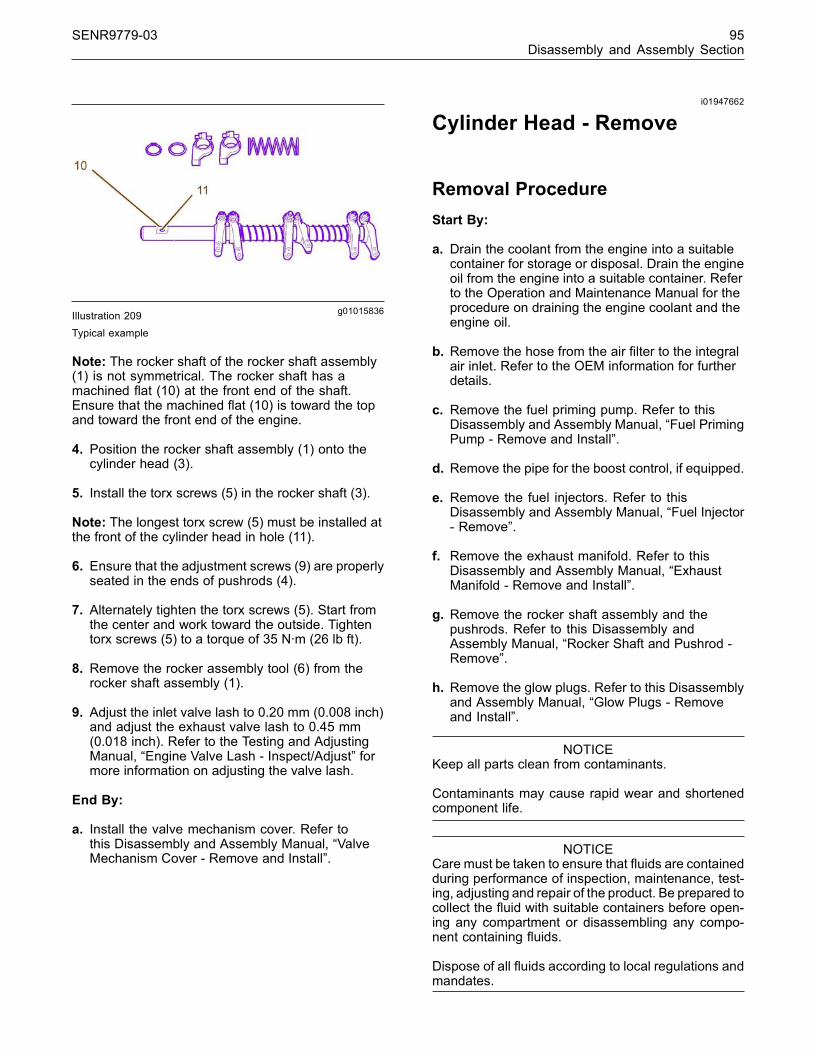
SENR9779-03 95Disassembly and Assembly Section
g01015836Illustration 209Typical example
Note: The rocker shaft of the rocker shaft assembly(1) is not symmetrical. The rocker shaft has amachined flat (10) at the front end of the shaft.Ensure that the machined flat (10) is toward the topand toward the front end of the engine.
4. Position the rocker shaft assembly (1) onto thecylinder head (3).
5. Install the torx screws (5) in the rocker shaft (3).
Note: The longest torx screw (5) must be installed atthe front of the cylinder head in hole (11).
6. Ensure that the adjustment screws (9) are properlyseated in the ends of pushrods (4).
7. Alternately tighten the torx screws (5). Start fromthe center and work toward the outside. Tightentorx screws (5) to a torque of 35 N·m (26 lb ft).
8. Remove the rocker assembly tool (6) from therocker shaft assembly (1).
9. Adjust the inlet valve lash to 0.20 mm (0.008 inch)and adjust the exhaust valve lash to 0.45 mm(0.018 inch). Refer to the Testing and AdjustingManual, “Engine Valve Lash - Inspect/Adjust” formore information on adjusting the valve lash.
End By:
a. Install the valve mechanism cover. Refer tothis Disassembly and Assembly Manual, “ValveMechanism Cover - Remove and Install”.
i01947662
Cylinder Head - Remove
Removal ProcedureStart By:
a. Drain the coolant from the engine into a suitablecontainer for storage or disposal. Drain the engineoil from the engine into a suitable container. Referto the Operation and Maintenance Manual for theprocedure on draining the engine coolant and theengine oil.
b. Remove the hose from the air filter to the integralair inlet. Refer to the OEM information for furtherdetails.
c. Remove the fuel priming pump. Refer to thisDisassembly and Assembly Manual, “Fuel PrimingPump - Remove and Install”.
d. Remove the pipe for the boost control, if equipped.
e. Remove the fuel injectors. Refer to thisDisassembly and Assembly Manual, “Fuel Injector- Remove”.
f. Remove the exhaust manifold. Refer to thisDisassembly and Assembly Manual, “ExhaustManifold - Remove and Install”.
g. Remove the rocker shaft assembly and thepushrods. Refer to this Disassembly andAssembly Manual, “Rocker Shaft and Pushrod -Remove”.
h. Remove the glow plugs. Refer to this Disassemblyand Assembly Manual, “Glow Plugs - Removeand Install”.
NOTICEKeep all parts clean from contaminants.
Contaminants may cause rapid wear and shortenedcomponent life.
NOTICECare must be taken to ensure that fluids are containedduring performance of inspection, maintenance, test-ing, adjusting and repair of the product. Be prepared tocollect the fluid with suitable containers before open-ing any compartment or disassembling any compo-nent containing fluids.
Dispose of all fluids according to local regulations andmandates.
This document has been printed from SPI². Not for Resale

96 SENR9779-03Disassembly and Assembly Section
Note: The removal procedure is identical for thethree cylinder and the four cylinder engines.
g01039425Illustration 210Typical example
1. Disconnect the harness assembly from the coolanttemperature sensor (1).
2. Remove the setscrews (2). Remove the bypasstube (3) from the cylinder head (4). Remove theO-rings from the bypass tube (3).
g01039484Illustration 211
Typical example
g01039487Illustration 212
Sequence for tightening the setscrews for the three cylinder engine
g01039483Illustration 213Sequence for tightening the setscrews for the four cylinder engine
3. Refer to the illustration 212 for three cylinderengines or illustration 213 for four cylinderengines. Gradually loosen the setscrews (5) in thereverse numerical order. This will help preventdistortion of the cylinder head (4).
4. Remove the setscrews (5) from the cylinder head(4).
Note: The cylinder head (4) is heavy. To avoid injury,take care when the cylinder head (4) is lifted. Alsotake care not to damage the machined surfaces ofthe cylinder head (4) during lifting and lowering thecylinder head.
Note: Do not use a lever to separate the cylinderhead (4) from the cylinder block.
This document has been printed from SPI². Not for Resale

SENR9779-03 97Disassembly and Assembly Section
NOTICEPlace the cylinder head on a surface that will notscratch the face of the cylinder head.
5. Use a suitable lifting device and carefully lift thecylinder head (4) off the cylinder block.
6. Remove the cylinder head gasket and discard thecylinder head gasket.
7. Note the location of the dowels in the cylinderblock for installation purposes.
i01947663
Cylinder Head - Install
Installation ProcedureTable 24
Required Tools
Part Number Part Description Qty
21825607 Angle Gauge 1
NOTICEKeep all parts clean from contaminants.
Contaminants may cause rapid wear and shortenedcomponent life.
Note: The installation procedure is identical for thethree cylinder and the four cylinder engines. Unlessthe illustration is otherwise indicated, the illustrationsshow the four cylinder engine.
Note: Thoroughly clean the top of the cylinder block(1) and the bottom of the cylinder head (2). Ensurethat there is no debris in the cylinder bores, thecoolant passages, and the lubricant passages.
Note: Thoroughly clean the hole in the cylinder headfor the gas that is ventilated from the crankcase.Ensure that the hole is not restricted by debris and/oroil deposits.
g01039834Illustration 214Typical example
1. Install suitable studs (3) into the cylinder block(1) in the setscrew holes 2 and 3. Refer to theillustration 217 for the three cylinder and refer tothe illustration 218 for the four cylinder head.
Note: Do not use any sealant or compound on thecylinder head gasket (4).
2. Install the cylinder head gasket (4) onto the studs(3) and onto the dowels (5) in the top of thecylinder block (1).
g01039835Illustration 215Typical example
Note: The cylinder head (2) is heavy. To avoid injury,take care when the cylinder head (2) is lifted. Alsotake care not to damage the machined surfaces ofthe cylinder head (2) during lifting and lowering thecylinder head.
3. Use a suitable lifting device to install the cylinderhead (2).
Note: Ensure that the cylinder head (2) is positionedonto the dowels (5).
4. Remove the studs (3).
This document has been printed from SPI². Not for Resale
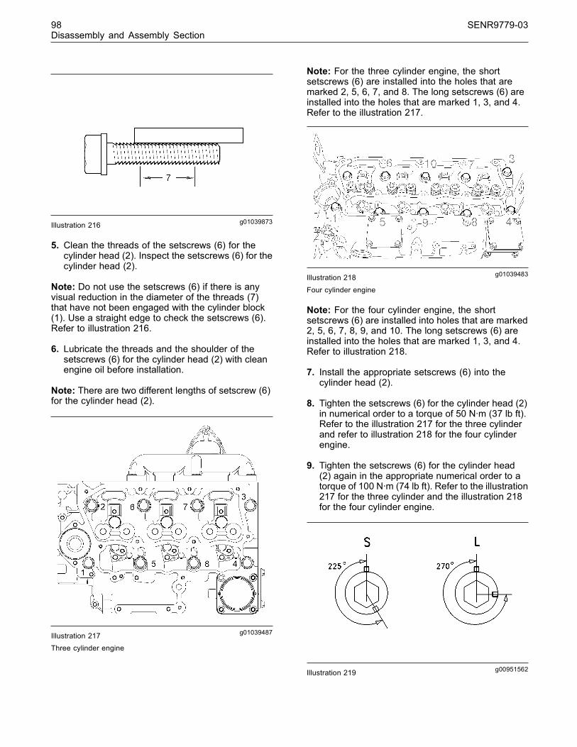
98 SENR9779-03Disassembly and Assembly Section
g01039873Illustration 216
5. Clean the threads of the setscrews (6) for thecylinder head (2). Inspect the setscrews (6) for thecylinder head (2).
Note: Do not use the setscrews (6) if there is anyvisual reduction in the diameter of the threads (7)that have not been engaged with the cylinder block(1). Use a straight edge to check the setscrews (6).Refer to illustration 216.
6. Lubricate the threads and the shoulder of thesetscrews (6) for the cylinder head (2) with cleanengine oil before installation.
Note: There are two different lengths of setscrew (6)for the cylinder head (2).
g01039487Illustration 217Three cylinder engine
Note: For the three cylinder engine, the shortsetscrews (6) are installed into the holes that aremarked 2, 5, 6, 7, and 8. The long setscrews (6) areinstalled into the holes that are marked 1, 3, and 4.Refer to the illustration 217.
g01039483Illustration 218
Four cylinder engine
Note: For the four cylinder engine, the shortsetscrews (6) are installed into holes that are marked2, 5, 6, 7, 8, 9, and 10. The long setscrews (6) areinstalled into the holes that are marked 1, 3, and 4.Refer to illustration 218.
7. Install the appropriate setscrews (6) into thecylinder head (2).
8. Tighten the setscrews (6) for the cylinder head (2)in numerical order to a torque of 50 N·m (37 lb ft).Refer to the illustration 217 for the three cylinderand refer to illustration 218 for the four cylinderengine.
9. Tighten the setscrews (6) for the cylinder head(2) again in the appropriate numerical order to atorque of 100 N·m (74 lb ft). Refer to the illustration217 for the three cylinder and the illustration 218for the four cylinder engine.
g00951562Illustration 219
This document has been printed from SPI². Not for Resale

SENR9779-03 99Disassembly and Assembly Section
10. Finally tighten the setscrews (6) for the cylinderhead (2) in the appropriate numerical order by anadditional amount of degrees.
a. Turn the short setscrews (2, 5, 6, 7, and 8) forthe three cylinder or turn the short setscrews(2, 5, 6, 7, 8, 9, and 10) for the four cylinderengine for an additional 225 degrees.
b. Turn the long setscrews (1, 3, and 4) for anadditional 270 degrees.
g01040089Illustration 220Typical example
11.Use 21825607 Angle Gauge in order to achievethe correct final torque.
12. Install the angle gauge (8) onto a suitable ratchetwrench (9). Refer to the appropriate illustration forthe first setscrew (6) of the tightening sequence,illustration 217 for the three cylinder and illustration218 for the four cylinder engine. Position the stop(10) against a suitable protrusion on the cylinderhead (2) in order to prevent movement of theangle gauge (8) in a clockwise direction. Alignthe pointer (11) of the angle gauge (8) with theappropriate angle on the dial of the angle gauge.Tighten the appropriate setscrew (6) until thepointer aligns with the zero on the dial of the anglegauge (8).
13.Repeat Step 12 for all of the cylinder headsetscrews (6) in the correct tightening sequence.Refer to illustration 217 for the three cylinder andillustration 218 for the four cylinder engine.
Note: The following alternative method can be usedif 21825607 Angle Gauge is not available.
Note: For reference, 225 degrees of rotation is equalto 3.75 flats on the setscrew and 270 degrees ofrotation is equal to 4.5 flats on the setscrew.
14.Place an index mark on the cylinder head (2)in line with a corner of each setscrew (6). Makeanother mark in a counter clockwise direction andat the correct angle for the length of setscrew (6)on the edge of the setscrew.
15. Tighten the setscrews (6) for the cylinder head (2)in numerical order. Refer to the illustration 217 forthe three cylinder and illustration 218 for the fourcylinder engine.
16. Turn the short setscrews (2, 5, 6, 7, and 8) orturn the short setscrews (2, 5, 6, 7, 8, 9, and 10)through an additional 225 degrees.
g01040100Illustration 221Typical example
17.Apply 21820221 POWERPART Red RubberGrease to the new O-rings before the O-rings areinstalled onto the bypass tube (12). Install thenew O-rings onto the bypass tube (12). Install thebypass tube (12) into the cylinder head (2). Installthe setscrews (13).
18.Connect the harness assembly onto the coolanttemperature sensor (14).
End By:
a. Install the glow plugs. Refer to this Disassemblyand Assembly Manual, “Glow Plugs - Removeand Install”.
b. Install the rocker shaft and the pushrods. Refer tothis Disassembly and Assembly Manual, “RockerShaft and Pushrod - Install”.
c. Install the exhaust manifold. Refer to thisDisassembly and Assembly Manual, “ExhaustManifold - Remove and Install”.
d. Install the fuel injectors. Refer to this Disassemblyand Assembly Manual, “Fuel Injector - Install”.
e. Install the pipe for the boost control, if equipped.
f. Install the fuel priming pump. Refer to thisDisassembly and Assembly Manual, “Fuel PrimingPump - Remove and Install”.
g. Install the hose from the integral air inlet to theair filter. Refer to the OEM information for furtherdetails.
This document has been printed from SPI². Not for Resale
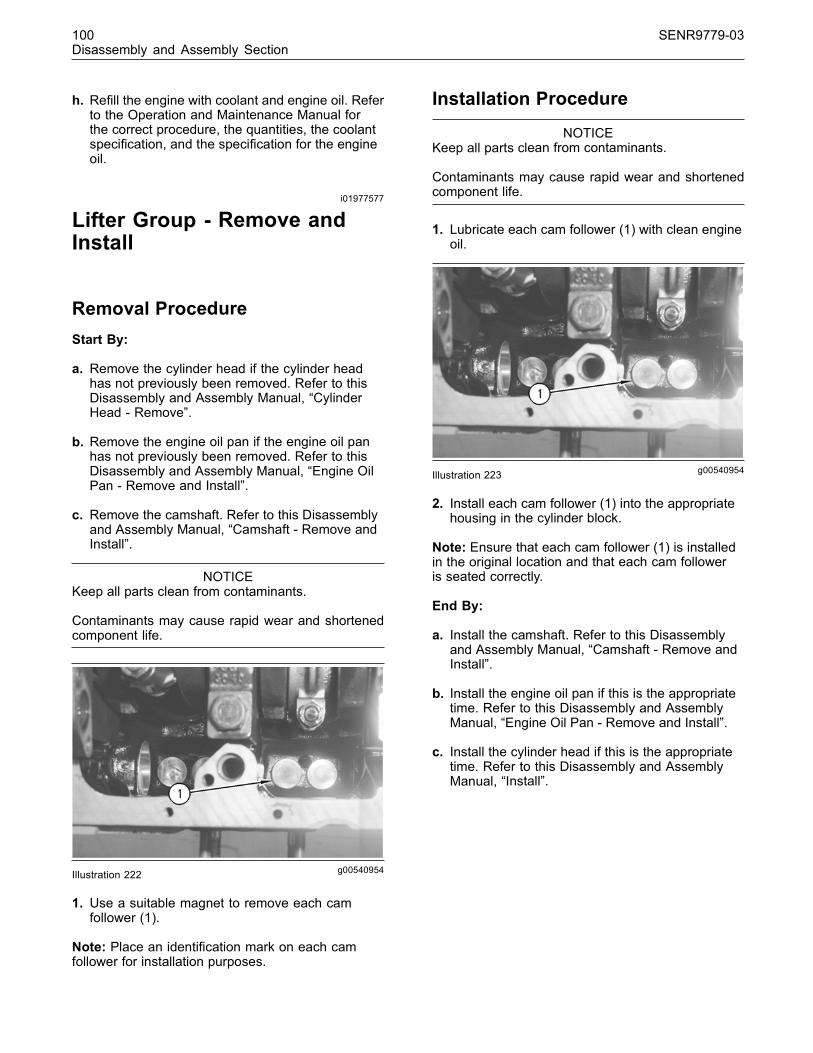
100 SENR9779-03Disassembly and Assembly Section
h. Refill the engine with coolant and engine oil. Referto the Operation and Maintenance Manual forthe correct procedure, the quantities, the coolantspecification, and the specification for the engineoil.
i01977577
Lifter Group - Remove andInstall
Removal ProcedureStart By:
a. Remove the cylinder head if the cylinder headhas not previously been removed. Refer to thisDisassembly and Assembly Manual, “CylinderHead - Remove”.
b. Remove the engine oil pan if the engine oil panhas not previously been removed. Refer to thisDisassembly and Assembly Manual, “Engine OilPan - Remove and Install”.
c. Remove the camshaft. Refer to this Disassemblyand Assembly Manual, “Camshaft - Remove andInstall”.
NOTICEKeep all parts clean from contaminants.
Contaminants may cause rapid wear and shortenedcomponent life.
g00540954Illustration 222
1. Use a suitable magnet to remove each camfollower (1).
Note: Place an identification mark on each camfollower for installation purposes.
Installation Procedure
NOTICEKeep all parts clean from contaminants.
Contaminants may cause rapid wear and shortenedcomponent life.
1. Lubricate each cam follower (1) with clean engineoil.
g00540954Illustration 223
2. Install each cam follower (1) into the appropriatehousing in the cylinder block.
Note: Ensure that each cam follower (1) is installedin the original location and that each cam followeris seated correctly.
End By:
a. Install the camshaft. Refer to this Disassemblyand Assembly Manual, “Camshaft - Remove andInstall”.
b. Install the engine oil pan if this is the appropriatetime. Refer to this Disassembly and AssemblyManual, “Engine Oil Pan - Remove and Install”.
c. Install the cylinder head if this is the appropriatetime. Refer to this Disassembly and AssemblyManual, “Install”.
This document has been printed from SPI². Not for Resale

SENR9779-03 101Disassembly and Assembly Section
i01977579
Camshaft - Remove and Install
Removal ProcedureStart By:
a. Remove the cylinder head if the cylinder headhas not previously been removed. Refer to thisDisassembly and Assembly Manual, “CylinderHead - Remove”.
b. Remove the front housing if the front housinghas not previously been removed. Refer to thisDisassembly and Assembly, “Housing (Front) -Remove”.
NOTICEKeep all parts clean from contaminants.
Contaminants may cause rapid wear and shortenedcomponent life.
1. Turn the engine upside-down so that the camfollowers are held in a position away from thecamshaft.
g00951938Illustration 224
2. Remove the thrust washer (1) if the thrust washerhas not previously been removed. Make a note ofthe location of the hollow dowel (2) for installationpurposes.
g00951934Illustration 225
NOTICEDo not damage the lobes or the bearings when thecamshaft is removed or installed.
3. Carefully remove the camshaft (3) from thecylinder block.
Installation Procedure
NOTICEKeep all parts clean from contaminants.
Contaminants may cause rapid wear and shortenedcomponent life.
Note: Ensure that the camshaft (3) is clean. Lubricatethe camshaft (3) with clean engine oil prior toinstallation.
NOTICEDo not damage the lobes or the bearings when thecamshaft is removed or installed.
1. Carefully install the camshaft (3) into the cylinderblock.
2. Put the thrust washer (1) in position if this is theappropriate time. Make sure that the thrust washer(1) is aligned with the hollow dowel (2).
End By:
a. Install the front housing if this is the appropriatetime. Refer to this Disassembly and AssemblyManual, “Housing (Front) - Install”.
b. Install the cylinder head if this is the appropriatetime. Refer to this Disassembly and AssemblyManual, “Cylinder Head - Install”.
This document has been printed from SPI². Not for Resale
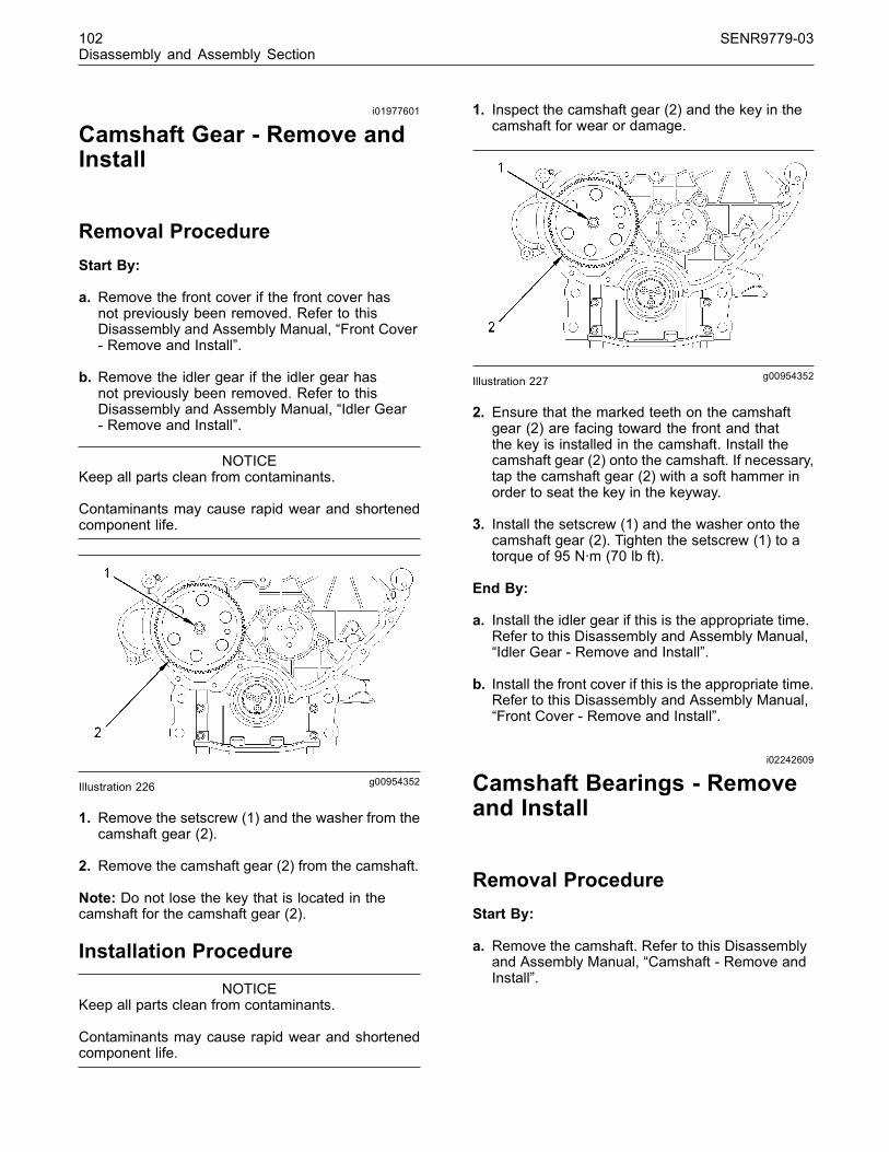
102 SENR9779-03Disassembly and Assembly Section
i01977601
Camshaft Gear - Remove andInstall
Removal ProcedureStart By:
a. Remove the front cover if the front cover hasnot previously been removed. Refer to thisDisassembly and Assembly Manual, “Front Cover- Remove and Install”.
b. Remove the idler gear if the idler gear hasnot previously been removed. Refer to thisDisassembly and Assembly Manual, “Idler Gear- Remove and Install”.
NOTICEKeep all parts clean from contaminants.
Contaminants may cause rapid wear and shortenedcomponent life.
g00954352Illustration 226
1. Remove the setscrew (1) and the washer from thecamshaft gear (2).
2. Remove the camshaft gear (2) from the camshaft.
Note: Do not lose the key that is located in thecamshaft for the camshaft gear (2).
Installation Procedure
NOTICEKeep all parts clean from contaminants.
Contaminants may cause rapid wear and shortenedcomponent life.
1. Inspect the camshaft gear (2) and the key in thecamshaft for wear or damage.
g00954352Illustration 227
2. Ensure that the marked teeth on the camshaftgear (2) are facing toward the front and thatthe key is installed in the camshaft. Install thecamshaft gear (2) onto the camshaft. If necessary,tap the camshaft gear (2) with a soft hammer inorder to seat the key in the keyway.
3. Install the setscrew (1) and the washer onto thecamshaft gear (2). Tighten the setscrew (1) to atorque of 95 N·m (70 lb ft).
End By:
a. Install the idler gear if this is the appropriate time.Refer to this Disassembly and Assembly Manual,“Idler Gear - Remove and Install”.
b. Install the front cover if this is the appropriate time.Refer to this Disassembly and Assembly Manual,“Front Cover - Remove and Install”.
i02242609
Camshaft Bearings - Removeand Install
Removal ProcedureStart By:
a. Remove the camshaft. Refer to this Disassemblyand Assembly Manual, “Camshaft - Remove andInstall”.
This document has been printed from SPI². Not for Resale

SENR9779-03 103Disassembly and Assembly Section
NOTICEKeep all parts clean from contaminants.
Contaminants may cause rapid wear and shortenedcomponent life.
g01130526Illustration 228Typical example
1. If the camshaft bearing (1) is worn or damageduse a suitable adapter in order to press thebearing out of the cylinder block.
Installation Procedure
NOTICEKeep all parts clean from contaminants.
Contaminants may cause rapid wear and shortenedcomponent life.
1. Ensure that the bearing housing in the cylinderblock is clean. Ensure that the oil hole in thebearing housing is clean and free from debris.
g01130526Illustration 229
Typical example
Note: Align the oil hole in camshaft bearing (2) withthe oil hole in the cylinder block.
2. Use a suitable adapter in order to press thecamshaft bearing (1) into the cylinder block.Continue to press the camshaft bearing (1) intothe cylinder block until the bearing is flush with theface of the recess in the cylinder block. Ensurethat the oil holes are still in alignment.
End By:
a. Install the camshaft. Refer to this Disassemblyand Assembly Manual, “Camshaft - Remove andInstall”.
i01958105
Engine Oil Pan - Remove andInstall
Removal Procedure
NOTICEKeep all parts clean from contaminants.
Contaminants may cause rapid wear and shortenedcomponent life.
NOTICECare must be taken to ensure that fluids are containedduring performance of inspection, maintenance, test-ing, adjusting and repair of the product. Be prepared tocollect the fluid with suitable containers before open-ing any compartment or disassembling any compo-nent containing fluids.
Dispose of all fluids according to local regulations andmandates.
Note: Ensure that the engine oil pan is fully supportedbefore the oil pan is removed. Particular care mustbe taken with the cast iron version of the engine oilsump as this version is heavy.
This document has been printed from SPI². Not for Resale
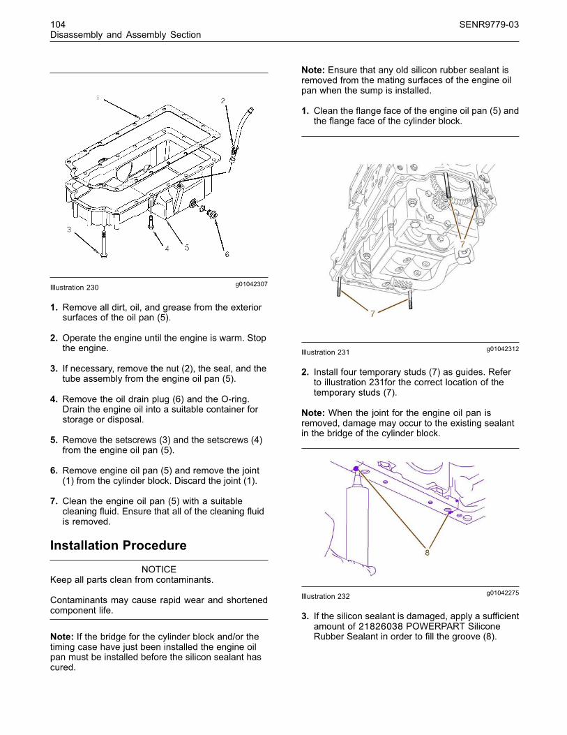
104 SENR9779-03Disassembly and Assembly Section
g01042307Illustration 230
1. Remove all dirt, oil, and grease from the exteriorsurfaces of the oil pan (5).
2. Operate the engine until the engine is warm. Stopthe engine.
3. If necessary, remove the nut (2), the seal, and thetube assembly from the engine oil pan (5).
4. Remove the oil drain plug (6) and the O-ring.Drain the engine oil into a suitable container forstorage or disposal.
5. Remove the setscrews (3) and the setscrews (4)from the engine oil pan (5).
6. Remove engine oil pan (5) and remove the joint(1) from the cylinder block. Discard the joint (1).
7. Clean the engine oil pan (5) with a suitablecleaning fluid. Ensure that all of the cleaning fluidis removed.
Installation Procedure
NOTICEKeep all parts clean from contaminants.
Contaminants may cause rapid wear and shortenedcomponent life.
Note: If the bridge for the cylinder block and/or thetiming case have just been installed the engine oilpan must be installed before the silicon sealant hascured.
Note: Ensure that any old silicon rubber sealant isremoved from the mating surfaces of the engine oilpan when the sump is installed.
1. Clean the flange face of the engine oil pan (5) andthe flange face of the cylinder block.
g01042312Illustration 231
2. Install four temporary studs (7) as guides. Referto illustration 231for the correct location of thetemporary studs (7).
Note: When the joint for the engine oil pan isremoved, damage may occur to the existing sealantin the bridge of the cylinder block.
g01042275Illustration 232
3. If the silicon sealant is damaged, apply a sufficientamount of 21826038 POWERPART SiliconeRubber Sealant in order to fill the groove (8).
This document has been printed from SPI². Not for Resale

SENR9779-03 105Disassembly and Assembly Section
g01042276Illustration 233
4. Also, apply a sufficient amount of new siliconrubber sealant if the silicon rubber sealant (9)between the cylinder block and the front cover isdamaged.
g01042307Illustration 234
5. Carefully position the joint (1) over the temporarystuds (7). Ensure that the engine oil pan isproperly supported while the engine oil pan (5) isinstalled onto the temporary studs (7). The castiron sump is heavy.
Note: New setscrews have sealant on the first 13 mm(0.5 inch) of the threads. In order to reuse the oldsetscrews, clean the old sealant from the setscrewsand apply 21820117 POWERPART Threadlock andNutlock to the setscrews.
6. Install the setscrews (4) in order to secure theengine oil pan (5) to the cylinder block. Tighten thesetscrews (4) finger tight.
g01042277Illustration 235
7. Remove the temporary studs (7) and install theremaining setscrew (3 and 4). Tighten the foursetscrews (10) to a torque of 22 N·m (16 lb ft).
8. Tighten remaining setscrews (3) and setscrews(4) to a torque of 22 N·m (16 lb ft).
9. Inspect the O-ring for the drain plug (6). Replacethe O-ring if it is necessary. Install the O-ring sealand drain plug (6). Tighten the drain plug (6) to atorque of 34 N·m (25 lb ft).
10. If necessary, install the seal and the tubeassembly in the engine oil pan. Tighten the nut (2)to a torque of 18 N·m (13 lb ft).
11. Fill the engine oil pan to the correct level that isindicated on the engine oil level gauge. Refer tothe Operation and Maintenance Manual, “RefillCapacities” for the lubrication system capacity ofthe engine.
This document has been printed from SPI². Not for Resale

106 SENR9779-03Disassembly and Assembly Section
i02242016
Balancer - Remove(Some 1104 Engines Only)
Removal ProcedureTable 25
Required Tools
Part Number Part Name Qty
27610225 Timing Pin (Balancer) 1
Start By:
a. Remove the engine oil pan. Refer to thisDisassembly and Assembly Manual, “Engine OilPan - Remove and Install”.
b. Remove the engine oil relief valve. Refer to thisDisassembly and Assembly Manual, “Engine OilRelief Valve - Remove and Install (Balancer Unitfor the Engine)”.
NOTICEKeep all parts clean from contaminants.
Contaminants may cause rapid wear and shortenedcomponent life.
NOTICECare must be taken to ensure that fluids are containedduring performance of inspection, maintenance, test-ing, adjusting and repair of the product. Be prepared tocollect the fluid with suitable containers before open-ing any compartment or disassembling any compo-nent containing fluids.
Dispose of all fluids according to local regulations andmandates.
1. Put the No. 1 cylinder at top dead center on thecompression stroke. Refer to this Testing andAdjusting Manual, “Fuel Injection Timing - Check”.
g01026243Illustration 236
2. Install the 27610225 Timing Pin into the balancer.Ensure that the timing pin (1) is fully located intothe drive shaft (2).
Note: The balancer is heavy. Take care when thebalancer is lifted and/or when the balancer is lowered.If the engine is not inverted, support the balancerbefore removing the setscrews (3).
3. Refer to the Note above and remove the setscrews(3). Use a suitable lifting device to remove thebalancer.
g01026290Illustration 237
Note: The balancer is a nonserviceable item. Use thefollowing procedure in order to remove the engine oilpump from the balancer.
4. Remove the setscrew (4) and the shaft (5).Remove the idler gear (6) and the thrust washer(7). Use a suitable adapter in order to press thebearing (8) from the idler gear (6). Discard thebearing (8).
This document has been printed from SPI². Not for Resale

SENR9779-03 107Disassembly and Assembly Section
5. Remove the nut (9). Use a suitable puller in orderto remove the gear (10) from the shaft.
6. Remove the setscrews (11). Remove the cover(12).
7. Remove the rotor assembly (13).
8. If necessary, remove the dowel (14) and thehollow dowel (15).
i01979489
Balancer - Install(Some 1104 Engines Only)
Installation ProcedureTable 26
Required Tools
Part Number Part Name Qty
27610225 Timing Pin (Balancer) 1
NOTICEKeep all parts clean from contaminants.
Contaminants may cause rapid wear and shortenedcomponent life.
1. Clean all of the components and inspect all ofthe components that were removed previously.Replace any component that is worn or damaged.
2. Clean the mating surfaces of the cylinder blockand the balancer.
g01026290Illustration 238
3. Install the rotor assembly (13). Check theclearance between the outer rotor and the body.Check the clearance between the inner rotor andthe outer rotor. Check the end play for the rotorassembly. Refer to the Specifications Manual,“Engine Oil Pump” for information.
4. Lubricate the rotor assembly (13) with cleanengine oil. Install the cover (12). Install thesetscrews (11). Tighten the setscrews (11) to atorque of 28 N·m (21 lb ft).
5. Ensure that the threads (16) of the shaft are cleanand dry. Position the oil pump gear (10) onto theshaft. Install the nut (9). Tighten the nut (9) to atorque of 95 N·m (70 lb ft).
6. Install a new bearing (8) into the idler gear (6).
7. Lubricate the bearing (8) with clean engine oil.Install the shaft (5) into the idler gear (6).
8. Position the idler gear (6) and the thrust washer(7) onto the balancer. Ensure that the threadsof the setscrew (4) are clean and dry. Apply21820117 POWERPART Threadlock and Nutlockto the threads of the setscrew (4) and install thesetscrew. Tighten the setscrew (4) to a torque of26 N·m (19 lb ft).
9. Check the end play for the idler gear (6). Refer tothe Specifications Manual, “Engine Oil Pump”.
10.Check the backlash between the gear (10) for theengine oil pump and the idler gear (6). Refer tothe Specifications Manual, “Engine Oil Pump”.
11.Ensure that the dowel (14) and the hollow dowel(15) are installed in the balancer.
This document has been printed from SPI². Not for Resale

108 SENR9779-03Disassembly and Assembly Section
12.Ensure that the No. 1 piston is at top dead centeron the compression stroke. Refer to the Testingand Adjusting Manual, “Fuel Injection Timing -Check”.
g01026330Illustration 239
13. Install two temporary studs (17) into the cylinderblock.
g01026243Illustration 240
14. Install the 27610225 Timing Pin (1) into the shaft(2).
15.Carefully position the balancer onto the temporarystuds (17). Ensure that the teeth of the idler gear(6) and the crankshaft gear are aligned.
16. Install two setscrews (3) into the center of thebalancer. Tighten the setscrews (3) to a torque of54 N·m (40 lb ft).
17.Remove the temporary studs (17) and install theremaining setscrews (3). Tighten the remainingsetscrews to a torque of 54 N·m (40 lb ft).
18.Remove the timing pin (1). Rotate the crankshaftin order to ensure that the balancer turns freely.
End By:
a. Install the engine oil relief valve. Refer to thisDisassembly and Assembly Manual, “Engine OilRelief Valve - Remove and Install (Balancer Unitfor the Engine)”.
b. Install the engine oil pan. Refer to this Disassemblyand Assembly Manual, “Engine Oil Pan - Removeand Install”.
i01979959
Piston Cooling Jets - Removeand Install
Removal ProcedureStart By:
a. Remove the engine oil pan. Refer to thisDisassembly and Assembly Manual, “Engine OilPan - Remove and Install”.
NOTICEKeep all parts clean from contaminants.
Contaminants may cause rapid wear and shortenedcomponent life.
g00952340Illustration 241
1. Remove the setscrew (1). Remove the pistoncooling jet assembly (2) from the cylinder block.
Note: The engine crankshaft may be rotated in orderto access all of the piston cooling jet assemblies.
This document has been printed from SPI². Not for Resale

SENR9779-03 109Disassembly and Assembly Section
Installation Procedure
NOTICEKeep all parts clean from contaminants.
Contaminants may cause rapid wear and shortenedcomponent life.
g00952363Illustration 242
1. Clean each piston cooling jet assembly (2).Inspect each assembly for damage and especiallycheck that the tube of the piston cooling jetassembly (2) has not been damaged. Ensure thatthe ball moves freely within each valve assemblyof the piston cooling jet (2). Replace any damagedassembly.
2. Install each piston cooling jet assembly (2) intothe cylinder block. Install the setscrew (1). Tightenthe setscrew (1) to a torque of 9 N·m (80 lb in).
Note: Ensure that piston cooling jet assembly (2)is properly located on the cylinder block. Refer tothe Specifications Manual, “Piston Cooling Jet” forthe correct procedure for the alignment of the pistoncooling jet.
End By:
a. Install the engine oil pan. Refer to this Disassemblyand Assembly Manual, “Engine Oil Pan - Removeand Install”.
i01939118
Pistons and Connecting Rods- Remove
Removal ProcedureStart By:
a. Remove the cylinder head. Refer to Disassemblyand Assembly, “Cylinder Head - Remove”.
b. Remove the engine oil pump. Refer toDisassembly and Assembly, “Engine Oil Pump- Remove”.
c. Remove the piston cooling jets. Refer toDisassembly and Assembly, “Piston Cooling Jets- Remove and Install”.
Note: The removal procedure is identical for thethree cylinder and the four cylinder engines. Theillustration shows the four cylinder engine.
NOTICEKeep all parts clean from contaminants.
Contaminants may cause rapid wear and shortenedcomponent life.
1. Position the pistons that are being removed at thebottom center position.
2. Remove the carbon buildup from the inner surfaceof the top of the cylinder liner.
3. Ensure that the connecting rod and the cap arecorrectly marked to the cylinder.
Note: Do not punch the connecting rod or stamp theconnecting rod assembly as this may cause damage.
4. Remove the torx screws (1) from the connectingrod.
g00970465Illustration 243Typical example
5. Remove the connecting rod cap (2) with thebearing shell.
6. Push the piston and the connecting rod throughthe top of the cylinder block.
Note: Make a mark under the piston on the pin bossin order to identify the cylinder. Always mark the frontpin boss to aid installation.
This document has been printed from SPI². Not for Resale

110 SENR9779-03Disassembly and Assembly Section
7. The bearing shell for the connecting rod and thebearing shell for the connecting rod cap mustbe placed with the correct rod and the correctconnecting rod cap.
8. Always tighten the connecting rod cap to theconnecting rod, when the assembly is out of theengine. Tighten the assembly to the followingtorque 20 N·m (14 lb ft).
i02280401
Pistons and Connecting Rods- Disassemble
Disassembly ProcedureStart By:
a. Remove the pistons and the connecting rods.Refer to Disassembly and Assembly, “Piston andConnecting Rods - Remove”.
NOTICERemoval of the piston pin bushing must be carriedout by personnel with the correct training. Also spe-cial machinery is required. For more information referto your authorized Perkins dealer or your Perkins dis-tributor.
NOTICEKeep all parts clean from contaminants.
Contaminants may cause rapid wear and shortenedcomponent life.
g00964585Illustration 244
1. Use a suitable ring expander in order to removethe three piston rings (1) and (2), and the oilcontrol ring (3) from the piston (6). Remove thelower connecting rod bearing from the connectingrod cap. Remove the upper connecting rodbearing from the connecting rod.
Note: If necessary, note the orientation of the oldpiston rings for assembly.
2. Use suitable pliers in order to remove the circlips(8).
3. Remove the piston pin (7) from the piston (6).
Note: If the piston pin cannot be removed by hand,heat the piston to a temperature of 45 ± 5 °C(113 ± 9 °F). Do not use a oxyacetylene torch to heatthe piston.
g01015731Illustration 245
4. Remove the bearing shells (9) from the connectingrod (10) and the connecting rod cap (11).
5. Use a suitable press and a suitable adapter inorder to remove the piston pin bushing (4) fromthe connecting rod (5).
This document has been printed from SPI². Not for Resale
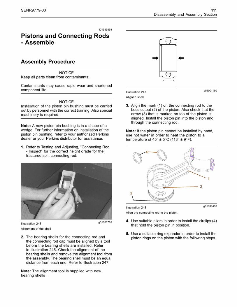
SENR9779-03 111Disassembly and Assembly Section
i01939858
Pistons and Connecting Rods- Assemble
Assembly Procedure
NOTICEKeep all parts clean from contaminants.
Contaminants may cause rapid wear and shortenedcomponent life.
NOTICEInstallation of the piston pin bushing must be carriedout by personnel with the correct training. Also specialmachinery is required.
Note: A new piston pin bushing is in a shape of awedge. For further information on installation of thepiston pin bushing, refer to your authorized Perkinsdealer or your Perkins distributor for assistance.
1. Refer to Testing and Adjusting, “Connecting Rod- Inspect” for the correct height grade for thefractured split connecting rod.
g01000785Illustration 246
Alignment of the shell
2. The bearing shells for the connecting rod andthe connecting rod cap must be aligned by a toolbefore the bearing shells are installed. Referto illustration 246. Check the alignment of thebearing shells and remove the alignment tool fromthe assembly. The bearing shell must be an equaldistance from each end. Refer to illustration 247.
Note: The alignment tool is supplied with newbearing shells .
g01001160Illustration 247Aligned shell
3. Align the mark (1) on the connecting rod to theboss cutout (2) of the piston. Also check that thearrow (3) that is marked on top of the piston isaligned. Install the piston pin into the piston andthrough the connecting rod.
Note: If the piston pin cannot be installed by hand,use hot water in order to heat the piston to atemperature of 45° ± 5°C (113° ± 9°F).
g01009410Illustration 248
Align the connecting rod to the piston.
4. Use suitable pliers in order to install the circlips (4)that hold the piston pin in position.
5. Use a suitable ring expander in order to install thepiston rings on the piston with the following steps.
This document has been printed from SPI². Not for Resale
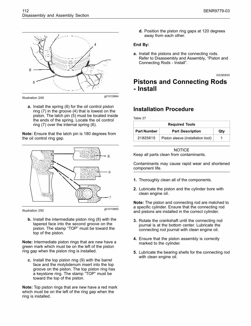
112 SENR9779-03Disassembly and Assembly Section
g01010864Illustration 249
a. Install the spring (6) for the oil control pistonring (7) in the groove (4) that is lowest on thepiston. The latch pin (5) must be located insidethe ends of the spring. Locate the oil controlring (7) over the internal spring (6).
Note: Ensure that the latch pin is 180 degrees fromthe oil control ring gap.
g01010865Illustration 250
b. Install the intermediate piston ring (8) with thetapered face into the second groove on thepiston. The stamp “TOP” must be toward thetop of the piston.
Note: Intermediate piston rings that are new have agreen mark which must be on the left of the pistonring gap when the piston ring is installed.
c. Install the top piston ring (9) with the barrelface and the molybdenum insert into the topgroove on the piston. The top piston ring hasa keystone ring. The stamp “TOP” must betoward the top of the piston.
Note: Top piston rings that are new have a red markwhich must be on the left of the ring gap when thering is installed.
d. Position the piston ring gaps at 120 degreesaway from each other.
End By:
a. Install the pistons and the connecting rods.Refer to Disassembly and Assembly, “Piston andConnecting Rods - Install”.
i02280830
Pistons and Connecting Rods- Install
Installation ProcedureTable 27
Required Tools
Part Number Part Description Qty
21825615 Piston sleeve (installation tool) 1
NOTICEKeep all parts clean from contaminants.
Contaminants may cause rapid wear and shortenedcomponent life.
1. Thoroughly clean all of the components.
2. Lubricate the piston and the cylinder bore withclean engine oil.
Note: The piston and connecting rod are matched toa specific cylinder. Ensure that the connecting rodand pistons are installed in the correct cylinder.
3. Rotate the crankshaft until the connecting rodjournal is at the bottom center. Lubricate theconnecting rod journal with clean engine oil.
4. Ensure that the piston assembly is correctlymarked to the cylinder.
5. Lubricate the bearing shells for the connecting rodwith clean engine oil.
This document has been printed from SPI². Not for Resale

SENR9779-03 113Disassembly and Assembly Section
g00999752Illustration 251
6. Lubricate the piston sleeve (1) with clean engineoil and install the piston sleeve.
Note: The arrow or the “FRONT” mark that is onthe top of the piston must be toward the front of theengine. Ensure that the piston rings are 120 degreesaway from each other.
Note: Ensure that the piston sleeve is installedcorrectly and that the piston can easily slide from thetool and into the cylinder.
7. Push the piston and the connecting rod assemblyinto the cylinder and onto the connecting rodjournal.
g01141423Illustration 252
Typical example
Note: New setscrews must be installed.
Note: Ensure that the etched number on connectingrod bearing cap (2) matches the etched number onconnecting rod.
8. Install the cap (2) with the bearing shell onto theconnecting rod journal and the new setscrews forthe cap.
9. Tighten the new setscrews to 20 N·m (14 lb ft).
Refer to Testing and Adjusting, “Piston Height -Inspect” for the correct procedure on checking theheight of the piston above the cylinder block.
10. Tighten the setscrews (3) to 70 N·m (51 lb ft).Again tighten the setscrews by 120 degrees. Referto the insert in the illustration 252. Check thatthere is no binding after this tightening sequencein step 9 and step 10.
End By:
a. Install the piston cooling jets. Refer to Disassemblyand Assembly, “Piston Cooling Jets - Removeand Install”.
b. Install the engine oil pump. Refer to Disassemblyand Assembly, “Engine Oil Pump - Install”.
c. Install the cylinder head. Refer to Disassemblyand Assembly, “Cylinder Head - Install”.
i01954554
Connecting Rod Bearings -Remove
Removal ProcedureStart By:
a. Remove the engine oil pump. Refer toDisassembly and Assembly, “Engine Oil Pump- Remove”.
NOTICEKeep all parts clean from contaminants.
Contaminants may cause rapid wear and shortenedcomponent life.
Note: Remove one pair of connecting rod caps ata time and install one pair at a time. Damage canoccur when the fractured split connecting rods areseparated.
1. In order to remove the connecting rod caps, rotatethe crankshaft in a clockwise direction until onepair of pistons is at the bottom center position.
Note: Check that the connecting rod and the cap arecorrectly marked to the cylinder. If the connectingrod assembly requires marking do not punch theconnecting rod assembly or stamp the connectingrod assembly as this may cause damage.
This document has been printed from SPI². Not for Resale

114 SENR9779-03Disassembly and Assembly Section
2. Remove the torx screws from the caps andremove both pair of caps with the bearing shells.Push both pair of connecting rods into the cylinder.Do not allow the connecting rods to contact thepiston cooling jets.
3. Carefully rotate the crankshaft in order to giveaccess to both pair of connecting rods.
4. Remove the bearing shells from the connectingrods and the caps.
5. Before continuing with the next pair of connectingrods, install all the new bearing shell into theconnecting rods and caps. Refer to Disassemblyand Assembly , “connecting rod bearing - install”.
i01953533
Connecting Rod Bearings -Install
Installation Procedure
NOTICEKeep all parts clean from contaminants.
Contaminants may cause rapid wear and shortenedcomponent life.
1. Carefully rotate the crankshaft in order to giveaccess to the connecting rod.
2. Ensure that the components are clean before thecomponents are assembled.
g01000785Illustration 253Alignment of the shell
Note: The alignment tool is supplied with the newbearing shells.
3. The bearing shell for the connecting rod mustbe aligned by a tool before the bearing shellsare installed. Refer to illustration 253. Check thealignment of the shell and remove the tool fromthe assembly. The bearing shell must be an equaldistance from each end. Refer to illustration 254.Lubricate both the bearing shells and lubricate thecrankshaft journal.
g01001160Illustration 254Aligned shell
4. Pull the connecting rod onto the crankshaft journaland install the correctly marked cap with thebearing shell onto the connecting rod.
Note: Do not allow the connecting rod into contactwith the piston cooling jet.
5. Install new torx screws into the connecting rodassembly. Tighten the torx screws to 20 N·m(14 lb ft). Rotate the crankshaft in order to checkfor binding. Again tighten the torx screws to70 N·m (51 lb ft).
Finally rotate the torx screws by 120 degrees.
Note: Rotate the crankshaft in order to recheck thatthere is no binding.
End By:
a. Install the piston cooling jets. Refer to Disassemblyand Assembly, “Piston Cooling Jets - Removeand Install”.
b. Install the engine oil pump. Refer to Disassemblyand Assembly, “Engine Oil Pump - Install”.
c. Install the cylinder head. Refer to Disassemblyand Assembly, “Cylinder Head - Install”.
This document has been printed from SPI². Not for Resale
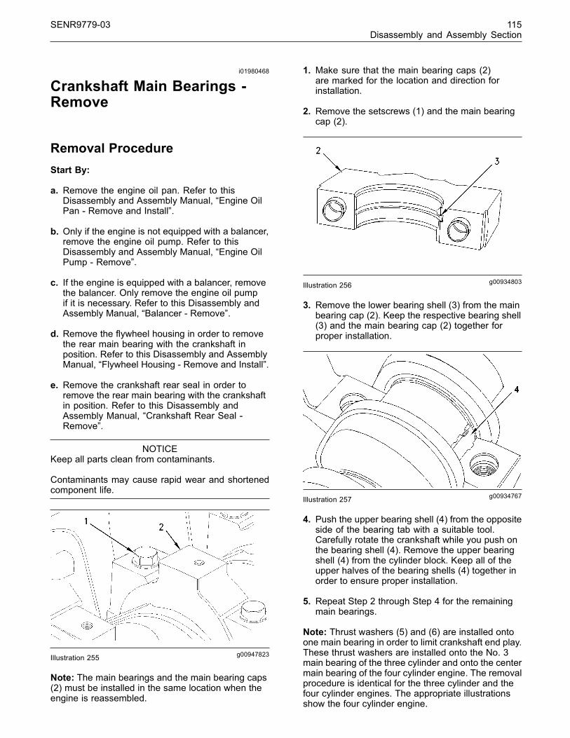
SENR9779-03 115Disassembly and Assembly Section
i01980468
Crankshaft Main Bearings -Remove
Removal ProcedureStart By:
a. Remove the engine oil pan. Refer to thisDisassembly and Assembly Manual, “Engine OilPan - Remove and Install”.
b. Only if the engine is not equipped with a balancer,remove the engine oil pump. Refer to thisDisassembly and Assembly Manual, “Engine OilPump - Remove”.
c. If the engine is equipped with a balancer, removethe balancer. Only remove the engine oil pumpif it is necessary. Refer to this Disassembly andAssembly Manual, “Balancer - Remove”.
d. Remove the flywheel housing in order to removethe rear main bearing with the crankshaft inposition. Refer to this Disassembly and AssemblyManual, “Flywheel Housing - Remove and Install”.
e. Remove the crankshaft rear seal in order toremove the rear main bearing with the crankshaftin position. Refer to this Disassembly andAssembly Manual, “Crankshaft Rear Seal -Remove”.
NOTICEKeep all parts clean from contaminants.
Contaminants may cause rapid wear and shortenedcomponent life.
g00947823Illustration 255
Note: The main bearings and the main bearing caps(2) must be installed in the same location when theengine is reassembled.
1. Make sure that the main bearing caps (2)are marked for the location and direction forinstallation.
2. Remove the setscrews (1) and the main bearingcap (2).
g00934803Illustration 256
3. Remove the lower bearing shell (3) from the mainbearing cap (2). Keep the respective bearing shell(3) and the main bearing cap (2) together forproper installation.
g00934767Illustration 257
4. Push the upper bearing shell (4) from the oppositeside of the bearing tab with a suitable tool.Carefully rotate the crankshaft while you push onthe bearing shell (4). Remove the upper bearingshell (4) from the cylinder block. Keep all of theupper halves of the bearing shells (4) together inorder to ensure proper installation.
5. Repeat Step 2 through Step 4 for the remainingmain bearings.
Note: Thrust washers (5) and (6) are installed ontoone main bearing in order to limit crankshaft end play.These thrust washers are installed onto the No. 3main bearing of the three cylinder and onto the centermain bearing of the four cylinder engine. The removalprocedure is identical for the three cylinder and thefour cylinder engines. The appropriate illustrationsshow the four cylinder engine.
This document has been printed from SPI². Not for Resale

116 SENR9779-03Disassembly and Assembly Section
g00934744Illustration 258Typical example
6. Remove the lower half of the thrust washer (5)from each side of the appropriate main bearingcap.
g00947753Illustration 259Typical example
7. Remove the upper half of the thrust washer (6)from each side of the appropriate main bearing inthe cylinder block with a suitable tool. Carefullyrotate the crankshaft while you push on the thrustwasher (6). If necessary, move the crankshaft tothe front or to the rear of the engine in order toloosen a tight thrust washer (6).
i01980478
Crankshaft Main Bearings -Install(Crankshaft in Position)
Installation Procedure
NOTICEKeep all parts clean from contaminants.
Contaminants may cause rapid wear and shortenedcomponent life.
g01026621Illustration 260
g00934767Illustration 261
Note: Ensure that the lower bearing shells (3), theupper bearing shells (4), and the appropriate mainbearing caps (2) are kept in sets and in the correctsequence for installation.
1. Ensure that all of the main bearing caps (2) areclean and dry. Ensure that both of the hollowdowels (1) are not damaged and that the hollowdowels are securely in place within the mainbearing cap (2).
This document has been printed from SPI². Not for Resale

SENR9779-03 117Disassembly and Assembly Section
2. Gently wipe the lower bearing shells (3) and theupper bearing shells (4) in order to ensure that thebearing shells are clean and dry. Inspect the lowerbearing shells (3) and the upper bearing shells(4). If necessary, replace the bearing shells thatare worn or damaged.
Note: Bearing shells must be replaced in pairs. If apair of bearing shells need to be replaced, considerreplacing all of the bearing shells at the same time.
Note: The upper bearing shell for the No. 1 crankshaftjournal has a lubricating oil slot. The remaining upperbearing shells have an oil hole for lubrication. All newupper bearing shells will have the slot for lubrication.
3. Gently wipe the main journals of the crankshaft inorder to ensure that the main journals are cleanand dry.
4. Lubricate the bearing surface of the upper bearingshell (4) and lubricate the appropriate main journalwith clean engine oil.
Note: Ensure that the upper bearing shell (4) isinstalled so that the bearing tabs fit into the notch inthe cylinder block.
NOTICEOnly the upper half of the main bearing has lubricationholes. Make sure the upper half of the main bearingis installed correctly in the cylinder block to ensureproper lubrication.
5. Slide the upper bearing shell (4) into positionbetween the appropriate crankshaft journal andthe cylinder block.
6. Lubricate the bearing face of the appropriate lowerbearing shell (3) with clean engine oil.
Note: Ensure that the lower bearing shell (3) isinstalled so that the bearing tab fits into the notch inthe appropriate main bearing cap.
7. Install the lower bearing shell (3) into theappropriate main bearing cap (2). Install the mainbearing cap (2) into the appropriate position andensure that the hollow dowels (1) are locatedwithin the main bearing cap and within therecesses in the cylinder block.
8. Repeat Step 4 through Step 7 for the remainingmain bearings.
Note: Thrust washers (5) and (6) are installed ontoone main bearing in order to limit crankshaft end play.These thrust washers are installed onto No. 3 mainbearing of the three cylinder and onto the center mainbearing of the four cylinder engine. The installationprocedure is identical for the three cylinder and thefour cylinder engines. The appropriate illustrationsshow the four cylinder engine.
g00947861Illustration 262Typical example
9. Gently wipe the upper thrust washers (6) and thelower thrust washers (5) in order to ensure thatthe thrust washers are clean and dry. Inspect theupper thrust washers (6) and the lower thrustwashers (5). If necessary, replace any damagedthrust washers.
10. Lightly lubricate the upper thrust washers (6) withclean engine oil. Install the upper thrust washers(6) onto each side of the appropriate main bearingin the cylinder block. The grooves on the upperthrust washers (6) must be located against thecrankshaft. If necessary, move the crankshaft tothe front or to the rear in order to install the thrustwashers (6).
g00934744Illustration 263
Typical example
This document has been printed from SPI². Not for Resale

118 SENR9779-03Disassembly and Assembly Section
11. Lightly lubricate the lower thrust washers (5) withclean engine oil. Install the lower thrust washers(5) onto each side of the appropriate main bearingcap. The grooves on the lower thrust washers (5)must be located against the crankshaft.
g01026633Illustration 264
12. Lubricate the threads of the setscrews (7) withclean engine oil.
13. Install the setscrews (7). Tighten the setscrews(7) to a torque of 245 N·m (181 lb ft).
14.Rotate the crankshaft in order to ensure that thecrankshaft turns freely.
g01026647Illustration 265
15.Check the crankshaft end play. Use a prybarto move the crankshaft toward the front of theengine. Use a suitable feeler gauge to measurethe end play (8) between rear thrust washer (5)and the crankshaft. The maximum permissiblecrankshaft end play is 0.51 mm (0.020 inch).
End By:
a. Install the rear bridge. Refer to this Disassemblyand Assembly Manual, “Crankshaft - Install”.
b. Install the crankshaft rear seal. Refer to thisDisassembly and Assembly Manual, “CrankshaftRear Seal - Install”.
c. Install the flywheel housing. Refer to thisDisassembly and Assembly Manual, “FlywheelHousing - Remove and Install”.
d. If the engine is equipped with a balancer and theengine oil pump was removed from the balancer,install the engine oil pump. Install the balancer.Refer to this Disassembly and Assembly Manual,“Balancer - Install”.
e. If the engine is not equipped with a balancer, installthe engine oil pump. Refer to this Disassemblyand Assembly Manual, “Engine Oil Pump - Install”.
f. Install the engine oil pan. Refer to this Disassemblyand Assembly Manual, “Engine Oil Pan - Removeand Install”.
i01981186
Crankshaft - Remove
Removal ProcedureStart By:
a. Remove the engine oil pan. Refer to thisDisassembly and Assembly Manual, “Engine OilPan - Remove and Install”.
b. Only if the engine is not equipped with a balancer,remove the engine oil pump. Refer to thisDisassembly and Assembly Manual, “Engine OilPump - Remove”.
c. If the engine is equipped with a balancer, removethe balancer. Only remove the engine oil pumpif it is necessary. Refer to this Disassembly andAssembly Manual, “Balancer - Remove”.
d. Remove the flywheel housing. Refer to thisDisassembly and Assembly Manual, “FlywheelHousing - Remove and Install”.
e. Remove the crankshaft rear seal. Refer to thisDisassembly and Assembly Manual, “CrankshaftRear Seal - Remove”.
f. Remove the front housing. Refer to thisDisassembly and Assembly Manual, “Housing(Front) - Remove”.
This document has been printed from SPI². Not for Resale
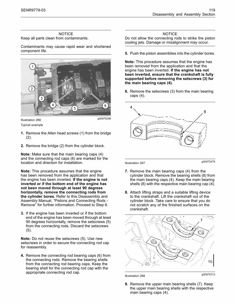
SENR9779-03 119Disassembly and Assembly Section
NOTICEKeep all parts clean from contaminants.
Contaminants may cause rapid wear and shortenedcomponent life.
g00975296Illustration 266Typical example
1. Remove the Allen head screws (1) from the bridge(2).
2. Remove the bridge (2) from the cylinder block.
Note: Make sure that the main bearing caps (4)and the connecting rod caps (6) are marked for thelocation and direction for installation.
Note: This procedure assumes that the enginehas been removed from the application and thatthe engine has been inverted. If the engine is notinverted or if the bottom end of the engine hasnot been moved through at least 90 degreeshorizontally, remove the connecting rods fromthe cylinder bores. Refer to this Disassembly andAssembly Manual, “Pistons and Connecting Rods -Remove” for further information. Proceed to Step 6.
3. If the engine has been inverted or if the bottomend of the engine has been moved through at least90 degrees horizontally, remove the setscrews (5)from the connecting rods. Discard the setscrews(5).
Note: Do not reuse the setscrews (5). Use newsetscrews in order to secure the connecting rod capfor reassembly.
4. Remove the connecting rod bearing caps (6) fromthe connecting rods. Remove the bearing shellsfrom the connecting rod bearing caps. Keep thebearing shell for the connecting rod cap with theappropriate connecting rod cap.
NOTICEDo not allow the connecting rods to strike the pistoncooling jets. Damage or misalignment may occur.
5. Push the piston assemblies into the cylinder bores.
Note: This procedure assumes that the engine hasbeen removed from the application and that theengine has been inverted. If the engine has notbeen inverted, ensure that the crankshaft is fullysupported before removing the setscrews (3) forthe main bearing caps (4).
6. Remove the setscrews (3) from the main bearingcaps (4).
g00975478Illustration 267
7. Remove the main bearing caps (4) from thecylinder block. Remove the bearing shells (8) fromthe main bearing caps (4). Keep the main bearingshells (8) with the respective main bearing cap (4).
8. Attach lifting straps and a suitable lifting deviceto the crankshaft. Lift the crankshaft out of thecylinder block. Take care to ensure that you donot scratch any of the finished surfaces on thecrankshaft.
g00975313Illustration 268
9. Remove the upper main bearing shells (7). Keepthe upper main bearing shells with the respectivemain bearing caps (4).
This document has been printed from SPI². Not for Resale

120 SENR9779-03Disassembly and Assembly Section
Note: Thrust washers (9) and (10) are installed ontoone main bearing in order to limit crankshaft endplay. These thrust washers are installed onto the No.3 main bearing of the three cylinder and the centermain bearing of the four cylinder engine. The removalprocedure is identical for the three cylinder and thefour cylinder engines. The appropriate illustrationsshow the four cylinder engine.
g01026869Illustration 269Typical example
10.Remove the upper thrust washers (9) from theappropriate main bearing block.
g01026870Illustration 270Typical example
11.Remove the lower thrust washers (10) from theappropriate main bearing cap.
i01981309
Crankshaft - Install
Installation Procedure
NOTICEKeep all parts clean from contaminants.
Contaminants may cause rapid wear and shortenedcomponent life.
g01027152Illustration 271
g01027338Illustration 272
Typical example
Note: Ensure that the upper bearing shells (1),the appropriate main bearing caps (2), and theappropriate lower bearing shells (3) are kept in setsand in the correct sequence for installation.
1. Ensure that all of the housings (4) in the cylinderblock for the upper bearing shells (1) are cleanand dry. Ensure that all of the lubrication passagesin the housings (4) are clean and free from debris.
This document has been printed from SPI². Not for Resale

SENR9779-03 121Disassembly and Assembly Section
2. Gently wipe the lower bearing shells (3) and theupper bearing shells (1) in order to ensure that thebearing shells are clean and dry. Inspect the lowerbearing shells (3) and the upper bearing shells(1). If necessary, replace the bearing shells thatare worn or damaged.
Note: Bearing shells must be replaced in pairs. If apair of bearing shells need to be replaced, considerreplacing all of the bearing shells at the same time.
Note: The upper bearing shell for the No. 1 crankshaftjournal has a lubricating oil slot. The remaining upperbearing shells (1) have an oil hole for lubrication. Allnew upper bearing shells (1) will have the slot forlubrication.
g01027337Illustration 273
3. Install the upper main bearing shells (1). Thebearing tabs (5) for the upper main bearing shells(1) must be located in the correct position inthe cylinder block (5). Lubricate the upper mainbearing shells (1) with clean engine oil.
4. Ensure that all of the main bearing caps (2) areclean and dry. Ensure that both of the hollowdowels (6) are not damaged and that two hollowdowels are securely in place within each of themain bearing caps (2).
Note: This procedure assumes that the enginehas been removed from the application and thatthe engine has been inverted. If the engine hasnot been inverted, ensure that the crankshaft iscompletely supported until the main bearing caps(2) and setscrews are completely installed.
5. Gently wipe the main journals of the crankshaftin order to ensure that the main journals areclean and dry. Attach suitable lifting straps to thecrankshaft.
6. Take care to ensure that you do not scratch anyof the finished surfaces on the crankshaft and thatyou do not damage the upper main bearing shells(1) or dislodge the upper main bearing shells. Thecrankshaft is heavy. Use suitable lifting equipmentto carefully lift the crankshaft into the upper mainbearing shells (1).
7. Install the appropriate lower main bearing shells(3) into main bearing caps (2) with the bearingtabs (7) in the correct position. Lubricate the lowermain bearing caps (2) with clean engine oil.
g01027339Illustration 274
Note: Do not install the No. 3 main bearing cap ofthe three cylinder or the center main bearing cap ofthe four cylinder engine at this time.
8. Use the hollow dowels (6) in order to locate theappropriate main bearing caps (2) and install themain bearing caps into the appropriate housing(4) in the cylinder block. Insert the setscrews (8)finger tight.
Note: Thrust washers (9) and (10) are installed ontoone main bearing in order to limit crankshaft end play.These thrust washers are installed onto the No. 3main bearing of the three cylinder and the center mainbearing of the four cylinder engine. The installationprocedure is identical for the three cylinder and thefour cylinder engines. The appropriate illustrationsshow the four cylinder engine.
This document has been printed from SPI². Not for Resale
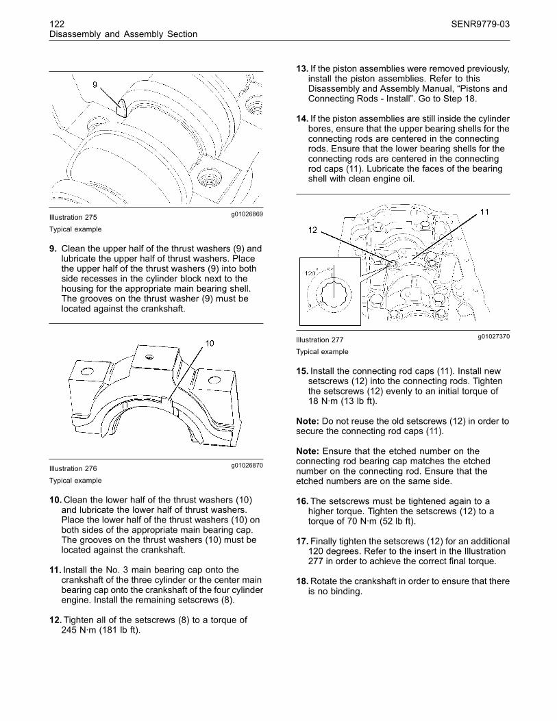
122 SENR9779-03Disassembly and Assembly Section
g01026869Illustration 275Typical example
9. Clean the upper half of the thrust washers (9) andlubricate the upper half of thrust washers. Placethe upper half of the thrust washers (9) into bothside recesses in the cylinder block next to thehousing for the appropriate main bearing shell.The grooves on the thrust washer (9) must belocated against the crankshaft.
g01026870Illustration 276
Typical example
10.Clean the lower half of the thrust washers (10)and lubricate the lower half of thrust washers.Place the lower half of the thrust washers (10) onboth sides of the appropriate main bearing cap.The grooves on the thrust washers (10) must belocated against the crankshaft.
11. Install the No. 3 main bearing cap onto thecrankshaft of the three cylinder or the center mainbearing cap onto the crankshaft of the four cylinderengine. Install the remaining setscrews (8).
12. Tighten all of the setscrews (8) to a torque of245 N·m (181 lb ft).
13. If the piston assemblies were removed previously,install the piston assemblies. Refer to thisDisassembly and Assembly Manual, “Pistons andConnecting Rods - Install”. Go to Step 18.
14. If the piston assemblies are still inside the cylinderbores, ensure that the upper bearing shells for theconnecting rods are centered in the connectingrods. Ensure that the lower bearing shells for theconnecting rods are centered in the connectingrod caps (11). Lubricate the faces of the bearingshell with clean engine oil.
g01027370Illustration 277Typical example
15. Install the connecting rod caps (11). Install newsetscrews (12) into the connecting rods. Tightenthe setscrews (12) evenly to an initial torque of18 N·m (13 lb ft).
Note: Do not reuse the old setscrews (12) in order tosecure the connecting rod caps (11).
Note: Ensure that the etched number on theconnecting rod bearing cap matches the etchednumber on the connecting rod. Ensure that theetched numbers are on the same side.
16. The setscrews must be tightened again to ahigher torque. Tighten the setscrews (12) to atorque of 70 N·m (52 lb ft).
17. Finally tighten the setscrews (12) for an additional120 degrees. Refer to the insert in the Illustration277 in order to achieve the correct final torque.
18.Rotate the crankshaft in order to ensure that thereis no binding.
This document has been printed from SPI². Not for Resale

SENR9779-03 123Disassembly and Assembly Section
g01027384Illustration 278
g00541498Illustration 279
19.Clean the bridge (13) and the face of thecylinder block. Apply a thin bead of 21826038POWERPART Silicone Adhesive onto the cornersof the seat for the bridge. Also apply POWERPARTSilicone Adhesive around the thread holes in theseat for the bridge. Use the following steps whenyou apply POWERPART Silicone Adhesive to thecylinder block and the bridge.
a. Apply a 3.0 mm (0.12 inch) bead of thePOWERPART Silicone Adhesive along thecorner of the top recess in the cylinder block.
Note: The maximum protrusion for the bridge (13)from the outside of the cylinder block is 0.075 mm(0.0029 inch).
b. Install the bridge (13). Use a straight edge toline up the bridge with the face of the cylinderblock. Tighten the socket head screws (14) to atorque of 16 N·m (12 lb ft). Tighten the sockethead screws (14) evenly.
c. When the bridge (13) is positioned and thesocket head screws (14) have been tightened,inject POWERPART Silicone Adhesive into thegroove that is at each end of the bridge. Thegroove must be completely filled.
g01027386Illustration 280
20.Check the crankshaft end play. Use a prybarto move the crankshaft toward the front of theengine. Use a feeler gauge to measure the endplay (15) between the rear thrust washer and thecrankshaft. Refer to the Specifications Manual,“Crankshaft” for the further information.
End By:
a. Install the front housing. Refer to this Disassemblyand Assembly Manual, “Housing (Front) - Install”.
b. Install the crankshaft rear seal. Refer to thisDisassembly and Assembly Manual, “CrankshaftRear Seal - Install”.
c. Install the flywheel housing. Refer to thisDisassembly and Assembly Manual, “FlywheelHousng - Remove and Install”.
d. If the engine is equipped with a balancer, installthe balancer. Refer to this Disassembly andAssembly Manual, “Balancer - Install”.
e. If the engine is not equipped with a balancer, installthe engine oil pump. Refer to this Disassemblyand Assembly Manual, “Engine Oil Pump - Install”.
f. Install the engine oil pan. Refer to this Disassemblyand Assembly Manual, “Engine Oil Pan - Removeand Install”.
This document has been printed from SPI². Not for Resale

124 SENR9779-03Disassembly and Assembly Section
i01981176
Crankshaft Gear - Remove andInstall
Removal Procedure
NOTICEKeep all parts clean from contaminants.
Contaminants may cause rapid wear and shortenedcomponent life.
g00970345Illustration 281
Typical example
Note: The crankshaft gear (1) may be a slip fit onthe crankshaft (3). If the crankshaft (3) is installedin the engine, use a suitable tool to ensure thatthe crankshaft gear (1) is not a slip fit before thecrankshaft is removed from the engine.
1. If the crankshaft gear (1) is a slip fit on thecrankshaft (3), use a suitable tool to remove thecrankshaft gear and proceed to Step 4.
2. If the crankshaft gear (1) is not a slip fit on thecrankshaft (3), remove the crankshaft from theengine. Refer to this Disassembly and AssemblyManual, “Crankshaft - Remove”.
3. Use suitable tooling to remove the crankshaft gear(1) from the crankshaft (3).
4. Remove the key (2) from the crankshaft (3).
Installation Procedure
NOTICEKeep all parts clean from contaminants.
Contaminants may cause rapid wear and shortenedcomponent life.
g00970345Illustration 282Typical example
1. Thoroughly clean the journal on the crankshaft(3) for the crankshaft gear (1) and the keywayslot for the key (2). Inspect the journal for thecrankshaft gear (1), the keyway slot, and the keyfor wear and/or damage. If necessary, replace anydamaged component.
2. Install the key (2) into the keyway slot in thecrankshaft (3).
Note: The crankshaft gear (1) may be a slip fit onthe crankshaft (3).
3. Check if the crankshaft gear (1) is a slip fit on thecrankshaft (3). If the crankshaft gear (1) is a slip fiton the crankshaft (3), proceed to Step 5.
Note: Ensure that heat is applied to the crankshaftgear (1) only. Do not apply heat directly onto thecrankshaft (3).
Note: Ensure that suitable clothing is worn in order tohandle the heated crankshaft gear.
4. If the crankshaft gear is not a slip fit on thecrankshaft, heat the crankshaft gear in an ovento 200 °C (392 °F).
5. Ensure that the shoulder on the crankshaft gear(1) is installed toward the front of the crankshaft(3). Install the crankshaft gear (1) onto thecrankshaft (3) and the key (2).
This document has been printed from SPI². Not for Resale

SENR9779-03 125Disassembly and Assembly Section
End By:
a. If the crankshaft was removed from the engine,install the crankshaft (3) at an appropriate time.Refer to this Disassembly and Assembly Manual,“Crankshaft - Install”.
i01981742
Bearing Clearance - Check
Measurement ProcedureTable 28
Required Tools
Description Qty
Plastic Gauge (Green)0.025 to 0.076 mm(0.001 to 0.003 inch)
1
Plastic Gauge (Red)0.051 to 0.152 mm(0.002 to 0.006 inch)
1
Plastic Gauge (Blue)0.102 to 0.229 mm(0.004 to 0.009 inch)
1
Plastic Gauge (Yellow)0.230 to 0.510 mm(0.009 to 0.020 inch)
1
NOTICEKeep all parts clean from contaminants.
Contaminants may cause rapid wear and shortenedcomponent life.
Note: Perkins does not recommend the checking ofthe actual clearances of the bearing shells particularlyon small engines. This is because of the possibilityof obtaining inaccurate results and the possibility ofdamaging the bearing shell or the journal surfaces.Each Perkins bearing shell is quality checked byPerkins for specific wall thickness.
Note: The measurements should be withinspecifications and the correct bearing shells shouldbe used. No further checks are necessary if themain journals and the bearing shells were measuredduring disassembly of the engine. No further checksare necessary if the crank pins of the crankshaftand the bearing shells were checked during thedisassembly of the connecting rods. However, PlasticGauge is an acceptable method if the technicianstill wants to measure the clearance of the bearingshell. Plastic Gauge is less accurate on journals withsmall diameters if clearances are less than 0.10 mm(0.004 inch).
NOTICELead wire, shim stock or a dial bore gauge can dam-age the bearing surfaces.
The technician must be very careful to use PlasticGauge correctly. The following points must beremembered:
• Ensure that the backs of the bearing shells and thebores of the bearing shells are clean and dry.
• If the bearing shells have locking tabs ensure thatthe locking tabs are properly seated in the tabgrooves.
• The crankshaft must be free of oil at the contactpoints of the Plastic Gauge.
g01010832Illustration 283Typical example
1. Put a piece of the Plastic Gauge (1) on the crownof the bearing shell that is in the cap.
Note: Do not allow the Plastic Gauge (1) to extendover the edge of the bearing shell.
2. Use the correct torque-turn specifications in orderto install the bearing cap. Do not use an impactwrench. Be careful not to dislodge the bearingshell when the cap is installed.
Note: Do not turn the crankshaft when the PlasticGauge (1) is installed.
3. Carefully remove the bearing cap, but do notremove the Plastic Gauge (1). Measure the widthof the Plastic Gauge (1) while the Plastic Gaugeis in the bearing cap or on the crankshaft journal.Refer to the Illustration 283.
This document has been printed from SPI². Not for Resale

126 SENR9779-03Disassembly and Assembly Section
4. Remove all of the Plastic Gauge (1) before youinstall the bearing cap.
Note:When Plastic Gauge is used, the readings cansometimes be unclear. For example, all parts of thePlastic Gauge are not the same width. Measure themajor width in order to ensure that the parts are withinthe specification range. Refer to the SpecificationsManual, “Connecting Rod Bearing Journal” and referto the Specifications Manual, “Main Bearing Journal”for the correct clearances.
i02280117
Glow Plugs - Remove andInstall(If Equipped)
Removal Procedure
NOTICEKeep all parts clean from contaminants.
Contaminants may cause rapid wear and shortenedcomponent life.
Note: The removal procedure is identical for thethree cylinder and the four cylinder engines. Theillustrations show the four cylinder engine.
1. Turn the disconnect switch to the OFF position.
g01001306Illustration 284Typical example
2. Remove the setscrews (1). Remove the cover (2)from the cylinder head.
g01119840Illustration 285
3. Disconnect the harness assembly from the Deutchconnector(6) on the bus bar (7), if equipped.
4. Disconnect the harness assembly from the stud(9) on the bus bar (8), if equipped.
5. Loosen the nuts (4) that secure the bus bar (7) or(8) to the glow plugs (5).
6. Remove the bus bar from the glow plugs.
7. Remove the glow plugs from the cylinder head.
Installation Procedure
NOTICEKeep all parts clean from contaminants.
Contaminants may cause rapid wear and shortenedcomponent life.
Note: The installation procedure is identical for thethree cylinder and the four cylinder engines. Theillustrations show the four cylinder engine.
This document has been printed from SPI². Not for Resale

SENR9779-03 127Disassembly and Assembly Section
g01119840Illustration 286
Typical example
1. Clean the threads of the glow plugs.
2. Install the glow plugs (5) into the cylinder head.Tighten the glow plugs to a torque of 15 N·m(11 lb ft).
3. Position the bus bar (7) or (8) onto the glow plugs.Tighten the nuts (4) on the glow plugs to a torqueof 2 N·m (17 lb in).
4. Connect the harness assembly to the Deutchconnector (5) on the bus bar (7), if equipped.
5. Connect the harness assembly to the stud (9) onthe bus bar (8), if equipped.
g01001306Illustration 287Typical example
6. Position the cover (2) onto the cylinder head.Install the setscrews (1). Tighten the setscrews toa torque of 9 N·m (80 lb in).
7. Turn the disconnect switch to the ON position.
i02011941
V-Belts - Remove and Install
Removal Procedure
g01015311Illustration 288
1. Loosen the setscrew (1), and the tensionadjustment setscrew (2). Slide the alternatortoward the engine.
2. Maneuver the V-belts around the fan and removethe V-belts.
Note: Never replace only one V-belt. Always replacethe V-belts as a set.
This document has been printed from SPI². Not for Resale

128 SENR9779-03Disassembly and Assembly Section
Installation Procedure
g01015311Illustration 289
1. Install the V-belts behind the fan and onto thecorrect pulleys.
2. Adjust the tension on the V-belts by moving thealternator away from the engine. Tighten thetension adjustment setscrew (2) after the correctbelt tension is made. Refer to Specifications,“Belt Tension Chart” for the correct tension of theV-belts. Tighten the tension adjustment setscrew(2) to a torque of 78 N·m (58 lb ft).
3. Tighten the setscrew (1) to a torque of 22 N·m(16 lb ft).
4. Tighten the nut (1) to a torque of 22 N·m (16 lb ft).
i01987612
Fan - Remove and Install
Removal ProcedureStart By:
a. Remove the V-Belts. Refer to this Disassemblyand Assembly Manual, “V-Belts - Remove andInstall”.
Note: The removal procedure is identical for thethree cylinder and the four cylinder engines. Theillustration shows the four cylinder engine.
g00926178Illustration 290Typical example
1. Remove the setscrews (1).
2. Remove the fan.
3. If equipped, remove the extension for the fan.
4. Remove the fan pulley.
Installation ProcedureNote: The installation procedure is identical for thethree cylinder and the four cylinder engines. Theillustration shows the four cylinder engine.
1. Inspect the condition of the fan pulley. Replace thefan pulley, if necessary.
2. Install the fan pulley.
3. If the engine is equipped with an extension for thefan, install the extension.
4. Inspect the condition of the fan and replace thefan, if necessary.
5. Install the fan.
g00926178Illustration 291Typical example
This document has been printed from SPI². Not for Resale

SENR9779-03 129Disassembly and Assembly Section
6. Install the setscrews (1). Tighten the setscrews (1)to a torque of 12 N·m (9 lb ft).
End By:
a. Install the V-Belts. Refer to this Disassembly andAssembly Manual, “V-Belts - Remove and Install”.
i02011983
Fan Drive - Remove and Install
Removal ProcedureStart By:
a. Remove the fan. Refer to this Disassembly andAssembly Manual, “Fan - Remove and Install”.
g00944500Illustration 292
1. Remove the setscrews (1) from the fan drive (2).
2. Remove the fan drive (2).
Installation Procedure
g00944500Illustration 293
1. Install the fan drive (2).
2. Install the setscrews (1). Tighten the setscrews toa torque of 44 N·m (32 lb ft).
End By:
a. Install the fan. Refer to this Disassembly andAssembly Manual, “Fan - Remove and Install”.
i02012014
Alternator - Remove
Removal Procedure1. Turn the battery disconnect switch to the OFFposition.
g00999883Illustration 294Typical Example
2. Place an index mark on all of the harnessassemblies that are connected to the alternator.
3. Disconnect the harness assemblies (4), (6), and(7) from the alternator.
4. Disconnect the ground harness assembly (5) fromthe alternator.
5. Loosen the nut and the setscrew (1).
6. Remove the tension adjustment setscrew (8) andslide the alternator (2) toward the engine. Removethe V-belts from the alternator pulley.
7. Remove the setscrew (1) from the alternatorbracket. Remove the alternator (2) from theengine.
8. If necessary, remove the nut (3) and the alternatorpulley from the alternator.
This document has been printed from SPI². Not for Resale
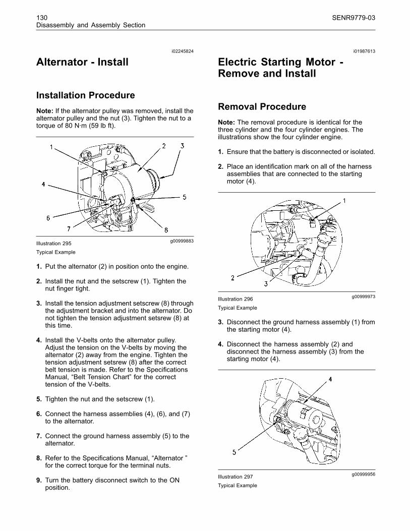
130 SENR9779-03Disassembly and Assembly Section
i02245824
Alternator - Install
Installation ProcedureNote: If the alternator pulley was removed, install thealternator pulley and the nut (3). Tighten the nut to atorque of 80 N·m (59 lb ft).
g00999883Illustration 295Typical Example
1. Put the alternator (2) in position onto the engine.
2. Install the nut and the setscrew (1). Tighten thenut finger tight.
3. Install the tension adjustment setscrew (8) throughthe adjustment bracket and into the alternator. Donot tighten the tension adjustment setsrew (8) atthis time.
4. Install the V-belts onto the alternator pulley.Adjust the tension on the V-belts by moving thealternator (2) away from the engine. Tighten thetension adjustment setsrew (8) after the correctbelt tension is made. Refer to the SpecificationsManual, “Belt Tension Chart” for the correcttension of the V-belts.
5. Tighten the nut and the setscrew (1).
6. Connect the harness assemblies (4), (6), and (7)to the alternator.
7. Connect the ground harness assembly (5) to thealternator.
8. Refer to the Specifications Manual, “Alternator ”for the correct torque for the terminal nuts.
9. Turn the battery disconnect switch to the ONposition.
i01987613
Electric Starting Motor -Remove and Install
Removal ProcedureNote: The removal procedure is identical for thethree cylinder and the four cylinder engines. Theillustrations show the four cylinder engine.
1. Ensure that the battery is disconnected or isolated.
2. Place an identification mark on all of the harnessassemblies that are connected to the startingmotor (4).
g00999973Illustration 296
Typical Example
3. Disconnect the ground harness assembly (1) fromthe starting motor (4).
4. Disconnect the harness assembly (2) anddisconnect the harness assembly (3) from thestarting motor (4).
g00999956Illustration 297Typical Example
This document has been printed from SPI². Not for Resale

SENR9779-03 131Disassembly and Assembly Section
5. Remove the nuts (5) from the studs.
6. Remove the electric starting motor (4) from theflywheel housing.
Installation ProcedureNote: The installation procedure is identical for thethree cylinder and the four cylinder engines. Theillustrations show the four cylinder engine.
g00999956Illustration 298Typical Example
1. Install the electric starting motor (4) onto theflywheel housing.
2. Install the nuts (5) onto the studs. Tighten the nuts(5) to a torque of 44 N·m (32 lb ft).
g00999973Illustration 299Typical Example
3. Connect the harness assembly (3), and theharness assembly (2) to the electric starting motor(4). Refer to the Specifications Manual, “StarterMotor” for the appropriate torques for the terminalnuts.
4. Connect the harness assembly (1) to the electricstarting motor (4). Refer to the SpecificationsManual, “Starter Motor” for the appropriate torquesfor the terminal nuts.
5. Turn the isolator for the battery to the ON positionor reconnect the battery.
i02641613
Vacuum Pump - Remove andInstall(Some 1104 engines only)
Removal Procedure1. Disconnect the oil line from the vacuum pumpand install a plastic cap onto the oil line. Install aplastic cap into the oil port in the vacuum pump.
2. Disconnect the vacuum line from the vacuumpump and install a plastic cap into the vacuumline. Install a plastic cap into the vacuum port inthe vacuum pump.
3. Remove the setscrews and remove the vacuumpump from the front housing.
4. Remove the joint from the front housing anddiscard the joint.
Installation Procedure1. Clean all dirt and oil from the surface area aroundthe ports in the vacuum pump. Clean the matingfaces on the vacuum pump and the front housing.
2. Install a new joint to the front housing and installthe vacuum pump onto the housing with thesetscrews. Tighten the setscrews to a torque of22 N·m (16 lb ft).
3. Remove the plastic caps from the vacuum lineand from the port in the vacuum pump. Install thevacuum line to the vacuum pump.
4. Remove the plastic caps from the oil line and fromthe port in the vacuum pump. Install the oil line tothe vacuum pump.
This document has been printed from SPI². Not for Resale

132 SENR9779-03Disassembly and Assembly Section
i01981808
Hydraulic Pump (Steering) -Remove
Removal Procedure1. Disconnect all of the hydraulic fluid lines from thehydraulic steering pump. Insert plastic caps into allof the open ports in the hydraulic steering pumpand insert plastic caps onto the open ends of thehydraulic fluid lines.
2. Remove the setscrews that secure the hydraulicsteering pump to the front housing and remove thehydraulic steering pump from the front housing.
3. Remove the O-ring from the front of the hydraulicsteering pump. Discard the O-ring.
i02641617
Hydraulic Pump (Steering) -Install
Installation Procedure1. Clean all dirt and oil from the surface area aroundthe ports in the hydraulic steering pump. Clean thelocation of the O-ring at the front of the hydraulicsteering pump. Clean the drive gear or the drivecoupling for the hydraulic steering pump. Cleanthe mating surfaces of the hydraulic steering pumpand the front housing.
2. Lubricate a new O-ring with clean engine oil.Install the O-ring onto the front of the hydraulicsteering pump.
3. Install the hydraulic steering pump onto the fronthousing with the setscrews. Tighten the setscrewsto a torque of 22 N·m (16 lb ft).
4. Remove the plastic caps from the hydraulic fluidlines and from the ports in the hydraulic steeringpump. Install the hydraulic fluid lines to thehydraulic steering pump.
This document has been printed from SPI². Not for Resale

SENR9779-03 133Index Section
Index
A
Accessory Drive - Remove and Install................... 85Installation Procedure ........................................ 86Removal Procedure ........................................... 85
Alternator - Install ................................................ 130Installation Procedure ...................................... 130
Alternator - Remove ............................................ 129Removal Procedure ......................................... 129
B
Balancer - Install (Some 1104 Engines Only)...... 107Installation Procedure ...................................... 107
Balancer - Remove (Some 1104 Engines Only).. 106Removal Procedure ......................................... 106
Bearing Clearance - Check ................................. 125Measurement Procedure ................................. 125
C
Camshaft - Remove and Install ........................... 101Installation Procedure ...................................... 101Removal Procedure ......................................... 101
Camshaft Bearings - Remove and Install ............ 102Installation Procedure ...................................... 103Removal Procedure ......................................... 102
Camshaft Gear - Remove and Install .................. 102Installation Procedure ...................................... 102Removal Procedure ......................................... 102
Connecting Rod Bearings - Install ........................ 114Installation Procedure ....................................... 114
Connecting Rod Bearings - Remove.................... 113Removal Procedure .......................................... 113
Crankcase Breather - Remove and Install............. 87Installation Procedure for the Diaphragm Valve.. 88Removal Procedure for the Diaphragm Valve.... 87
Crankshaft - Install............................................... 120Installation Procedure ...................................... 120
Crankshaft - Remove............................................ 118Removal Procedure .......................................... 118
Crankshaft Front Seal - Install ............................... 72Installation Procedure ........................................ 72
Crankshaft Front Seal - Remove........................... 71Removal Procedure ........................................... 71
Crankshaft Gear - Remove and Install ................ 124Installation Procedure ...................................... 124Removal Procedure ......................................... 124
Crankshaft Main Bearings - Install (Crankshaft inPosition).............................................................. 116Installation Procedure ....................................... 116
Crankshaft Main Bearings - Remove.................... 115Removal Procedure .......................................... 115
Crankshaft Pulley - Remove and Install ................ 68Removal and Installation of the Non-standardPulley (if equipped) .......................................... 69Removal and Installation of the Standard Pulley (ifequipped) ......................................................... 68Standard and Non-standard Pulleys.................. 68
Crankshaft Rear Seal - Install................................ 63Installation Procedure ........................................ 63
Crankshaft Rear Seal - Remove............................ 62Removal Procedure ........................................... 62
Crankshaft Wear Sleeve (Front) - Install ............... 73Installation Procedure ........................................ 73
Crankshaft Wear Sleeve (Rear) - Install................ 66Installation Procedure ........................................ 66
Crankshaft Wear Sleeve (Rear) - Remove............ 65Removal Procedure ........................................... 65
Cylinder Head - Install ........................................... 97Installation Procedure ........................................ 97
Cylinder Head - Remove ....................................... 95Removal Procedure ........................................... 95
D
Disassembly and Assembly Section........................ 4
E
Electric Starting Motor - Remove and Install ....... 130Installation Procedure ...................................... 131Removal Procedure ......................................... 130
Engine Oil Cooler - Install...................................... 48Installation Procedure for the Four CylinderEngine.............................................................. 50Installation Procedure for the Three CylinderEngine.............................................................. 48
Engine Oil Cooler - Remove.................................. 47Removal Procedure for Four Cylinder Engine ... 48Removal Procedure for Three Cylinder Engine.. 47
Engine Oil Filter Base - Remove and Install.......... 43Installation Procedure for a Spin-On Oil Filter ... 46Installation Procedure for an Oil Filter with aSeparate Filter Element ................................... 44Removal Procedure for a Spin-On Oil Filter ...... 45Removal Procedure for an Oil Filter with a SeparateFilter Element ................................................... 43
Engine Oil Pan - Remove and Install................... 103Installation Procedure ...................................... 104Removal Procedure ......................................... 103
Engine Oil Pump - Install (Engines Without aBalancer) ............................................................. 53Installation Procedure ........................................ 53
Engine Oil Pump - Remove (Engines Without aBalancer) ............................................................. 52Removal Procedure ........................................... 52
Engine Oil Relief Valve - Remove and Install(Balancer Unit for the 1104 engines only)............ 51Installation Procedure ........................................ 52Removal Procedure ........................................... 51
This document has been printed from SPI². Not for Resale
134 SENR9779-03Index Section
Engine Oil Relief Valve - Remove and Install (EngineOil Pump)............................................................. 50Installation Procedure ........................................ 51Removal Procedure ........................................... 50
Exhaust Elbow - Remove and Install (IfEquipped) ............................................................ 33Installation Procedure ........................................ 34Removal Procedure ........................................... 33
Exhaust Manifold - Remove and Install ................. 31Installation Procedure for the Four CylinderEngine.............................................................. 32Installation Procedure for the Three CylinderEngine.............................................................. 32Removal Procedure for the Four CylinderEngine.............................................................. 32Removal Procedure for the Three CylinderEngine.............................................................. 31
F
Fan - Remove and Install .................................... 128Installation Procedure ...................................... 128Removal Procedure ......................................... 128
Fan Drive - Remove and Install ........................... 129Installation Procedure ...................................... 129Removal Procedure ......................................... 129
Flywheel - Install.................................................... 61Installation Procedure ........................................ 61
Flywheel - Remove................................................ 61Removal Procedure ........................................... 61
Flywheel Housing - Remove and Install ................ 66Installation Procedure ........................................ 67Removal Procedure ........................................... 66
Front Cover - Remove and Install.......................... 73Installation Procedure ........................................ 74Removal Procedure ........................................... 73
Fuel Filter Base - Remove and Install ..................... 6Installation Procedure .......................................... 7Installation Procedure for the Element Filter........ 7Installation Procedure for the Spin-on Filter......... 8Removal Procedure ............................................. 6Removal Procedure for the Element Filter........... 6Removal Procedure for the Spin-on Filter............ 7
Fuel Injection Lines - Install ..................................... 9Installation Procedure .......................................... 9
Fuel Injection Lines - Remove................................. 9Removal Procedure ............................................. 9
Fuel Injection Pump - Install (Bosch EPVE for the1104 engines only)............................................... 24Installation Procedure ........................................ 24
Fuel Injection Pump - Install (Delphi DP210)......... 19Installation Procedure ........................................ 19
Fuel Injection Pump - Install (Delphi DPA) ............ 26Installation Procedure ........................................ 26
Fuel Injection Pump - Install (Delphi DPG)............ 22Installation Procedure ........................................ 22
Fuel Injection Pump - Install (Delphi STP)............. 20Installation Procedure ........................................ 20
Fuel Injection Pump - Remove (Bosch EPVE for the1104 engines only)............................................... 16Removal Procedure ........................................... 16
Fuel Injection Pump - Remove (Delphi DP210)...... 11Removal Procedure ............................................ 11
Fuel Injection Pump - Remove (Delphi DPA) ........ 17Removal Procedure ........................................... 17
Fuel Injection Pump - Remove (Delphi DPG)........ 14Removal Procedure ........................................... 14
Fuel Injection Pump - Remove (Delphi STP)......... 13Removal Procedure ........................................... 13
Fuel Injector - Install .............................................. 28Installation Procedure ........................................ 28
Fuel Injector - Remove .......................................... 27Removal Procedure ........................................... 27
Fuel Injector Cover - Remove and Install (IfEquipped) ............................................................ 10Installation Procedure ......................................... 11Removal Procedure ........................................... 10
Fuel Priming Pump - Remove and Install ................ 4Installation Procedure .......................................... 5Installation Procedure for Type 1 ......................... 5Installation Procedure for Type 2 ......................... 5Removal procedure.............................................. 4Removal Procedure for Type 1 ............................ 4Removal Procedure for Type 2 ............................ 4
G
Gear Group (Front) - Install ................................... 76Installation Procedure ........................................ 76
Gear Group (Front) - Remove ............................... 74Removal Procedure ........................................... 74
Glow Plugs - Remove and Install (If Equipped)... 126Installation Procedure ...................................... 126Removal Procedure ......................................... 126
H
Housing (Front) - Install ......................................... 84Installation Procedure ........................................ 84
Housing (Front) - Remove..................................... 83Removal Procedure ........................................... 83
Hydraulic Pump (Steering) - Install...................... 132Installation Procedure ...................................... 132
Hydraulic Pump (Steering) - Remove.................. 132Removal Procedure ......................................... 132
I
Idler Gear - Remove and Install............................. 78Installation Procedure ........................................ 80Removal Procedure ........................................... 78
Important Safety Information ................................... 2Inlet and Exhaust Valve Guides - Remove andInstall ................................................................... 39Installation Procedure ........................................ 40Removal Procedure ........................................... 39
This document has been printed from SPI². Not for Resale

SENR9779-03 135Index Section
Inlet and Exhaust Valve Seat Inserts - Remove andInstall ................................................................... 41Installation Procedure ........................................ 41Removal Procedure ........................................... 41
Inlet and Exhaust Valve Springs - Remove andInstall ................................................................... 34Installation Procedure ........................................ 35Removal Procedure ........................................... 34
Inlet and Exhaust Valves - Remove and Install ..... 36Installation Procedure ........................................ 37Removal Procedure ........................................... 36
L
Lifter Group - Remove and Install........................ 100Installation Procedure ...................................... 100Removal Procedure ......................................... 100
P
Piston Cooling Jets - Remove and Install............ 108Installation Procedure ...................................... 109Removal Procedure ......................................... 108
Pistons and Connecting Rods - Assemble ........... 111Assembly Procedure......................................... 111
Pistons and Connecting Rods - Disassemble ...... 110Disassembly Procedure .................................... 110
Pistons and Connecting Rods - Install.................. 112Installation Procedure ....................................... 112
Pistons and Connecting Rods - Remove............. 109Removal Procedure ......................................... 109
R
Rocker Shaft - Assemble....................................... 93Assembly Procedure.......................................... 93
Rocker Shaft - Disassemble .................................. 92Disassembly Procedure ..................................... 92
Rocker Shaft and Pushrod - Install........................ 94Installation Procedure ........................................ 94
Rocker Shaft and Pushrod - Remove.................... 91Removal Procedure ........................................... 91
T
Table of Contents..................................................... 3Turbocharger - Install ............................................ 30Installation Procedure ........................................ 30
Turbocharger - Remove ........................................ 29Removal Procedure ........................................... 29
V
V-Belts - Remove and Install ............................... 127Installation Procedure ...................................... 128Removal Procedure ......................................... 127
Vacuum Pump - Remove and Install (Some 1104engines only) ..................................................... 131Installation Procedure ...................................... 131Removal Procedure ......................................... 131
Valve Mechanism Cover - Remove and Install...... 90Installation Procedure ........................................ 90Removal Procedure ........................................... 90
W
Water Pump - Assemble........................................ 56Assembly Procedure.......................................... 56
Water Pump - Disassemble................................... 54Disassembly Procedure ..................................... 54
Water Pump - Install .............................................. 57Installation Procedure ........................................ 57
Water Pump - Remove .......................................... 54Removal Procedure ........................................... 54
Water Temperature Regulator - Remove andInstall ................................................................... 58Installation Procedure ........................................ 59Removal Procedure ........................................... 58
This document has been printed from SPI². Not for Resale

Copyright ©2007 Perkins Engines Company LimitedAll Rights Reserved Printed in U.K .This document has been printed from SPI². Not for Resale