directional air drilling techniques - igh · has evolved from the oil and gas drilling to the ......
TRANSCRIPT

Presented at “Short Course on Geothermal Drilling, Resource Development and Power Plants”, organized by UNU-GTP and LaGeo, in San Tecla, El Salvador, January 16-22, 2011.
1
GEOTHERMAL TRAINING PROGRAMME LaGeo S.A. de C.V.
DIRECTIONAL AND AIR DRILLING TECHNIQUES
Zosimo F. Sarmiento1 and Sverrir Thorhallsson2 1 FEDCO – Filtech Energy Drilling Corporation
Tesco Compound, RMT Industrial Complex Tunasan, Muntinlupa City, 1773 PHILIPPINES
[email protected] 2ISOR- Iceland Geosurvey
Grensásvegur 9, 108 Reykjavik ICELAND [email protected]
ABSTRACT
Drilling cost represents approximately 60% of the total cost of the steamfield and about 30% of the total steamfield and power plant cost. It is therefore imperative to prudently manage drilling operations to maintain project cost at desired levels of investment. Cost reduction, environmental restrictions and optimum targeting of wells led to the adoption of directional and air drilling techniques in the worldwide development of geothermal energy. The main focus of this paper is on the application of directional and air drilling techniques in geothermal well drilling operations. Directional drilling method has become very popular because of several advantages associated in improving the probability of intersecting high angle faults, and the capability to drill more wells in a single pad to mitigate impact to environment. More faults intersected by the well result in better production. Air drilling technique has been able to address problems associated but not limited to circulation losses, especially in maturing fields with significant pressure decline, differential sticking, water requirements and formation damage.
1. INTRODUCTION Directional drilling is a technique where the planned course of the well is deviated at pre-determined angle in order to intersect a subsurface target with a lateral distance and direction from the vertical. Figure 1 is a typical directionally drilled well with some throw from the vertical. Directional drilling has evolved from the oil and gas drilling to the geothermal industry. Historically, directional drilling was used primarily for remedial operations, either for side-tracking around stuck tools, bringing the well bore back to vertical, or in drilling relief wells to kill blowouts. In some cases, directional drilling was attempted for unethical purposes to cross property lines. To date, the very strict environmental requirements has led to the adoption of directional drilling technique in developing geothermal resources, especially those that are located in high elevation and rugged terrain.

Sarmiento and Thorhallsson 2 Directional and air drilling techniques
Air or aerated drilling involves the mixing of compressed air to the drilling fluid circulating system for the purpose of reducing the hydrostatic head in the wellbore. Aerated drilling is applied to attain a balance between the hydrostatic pressure and the formation or reservoir pressure in a loss zone. This condition is termed as balanced drilling. In some cases, where the wellbore pressure needs to be slightly lesser than the reservoir pressure, a slightly under-balance drilling is applied. Under this condition, the well is flowing at controlled pressure condition. Air drilling has been previously recognized to address circulation losses encountered during drilling once the well intersects a very permeable zone. When this happens, all the mud and cuttings will be lost into the zone instead of being lifted to the surface. During the process, the rig usually gets stuck as the cuttings trap the bit at the bottom. Ultimately, the drilling time increases and the chance of the well to be completed at target depth is reduced. When the well is completed, the well suffers damage because of the mud and the cuttings that invaded the loss zone. To date, the advantage of air drilling in attaining faster penetration rate in minimizing drilling problems, and in cleaning the well has made it a part of almost every geothermal drilling program worldwide. 2. APPLICATION OF DIRECTIONAL DRILLING 2.1 Sidetracking Side-tracking is where the original directional drilling technique evolved. Initial sidetracking technique was originally blind with the objective of just simply getting past a fish. Today, sidetracks are oriented and carefully planned with special tools to attain main objective. When a hole is lost and the integrity of the top section of casing is good, a sidetrack is recommended to make use of existing well cellar (Figure 2). 2.2 Inaccessible locations Drilling targets in a geothermal resource may be located inside a protected or environmentally sensitive area where surface activities are not permitted. This necessitates the location of drilling rigs at some distance away, requiring the well to be drilled directionally to reach targets (Figure 3).
FIGURE 1: A typical directionally drilled well with some throw from the vertical

Directional and air drilling techniques 3 Sarmiento and Thorhallsson
2.3 Fault intersection Structural faults, acting as the main fluid channel from the reservoir to the wellbore, are commonly targeted in geothermal wells to obtain better production. Fractures and faults are the common source of production from the geothermal reservoirs, unlike in petroleum reservoirs where there is inherently high porosity in the formation. Most of the dips of faults are inferred from surface measurements, and there is no assurance they behave the same underneath the formation (Figure 4). In view of this uncertainty, the likelihood of intersecting more fractures or faults are higher when drilling directional than vertical holes. 2.4 Well-forked completion Well-forked completions refer to a drilling technique where two or more legs are drilled in a single wellbore. This is made possible by plugging back at a certain depth and deviating a new hole towards another target (Figure 5). This technique allows the use of a completed well for another leg in the wellbore after drilling into a non-productive target or region in the reservoir. In many cases, it maximizes the capacity of the well casing when targets can be reasonably accessed from the current well location. This drilling technique was successfully tried in the Aidlin project area of the northwest Geysers in California. An average of 58% increase over the original well productivities was achieved, making it cost-effective in spite of the attendant problems drilling risks.
FIGURE 4: Example of a well drilled
to intersect a fault
FIGURE 5: Example of a multi-legged or
well forked-completion
FIGURE 2: Example of a side-tracked hole FIGURE 3: Directional drilled well to reach an environmentally sensitive area from the
outside or within its boundary

Sarmiento and Thorhallsson 4 Directional and air drilling techniques
2.5 Relief well Relief well is drilled to kill an uncontrollable well that encountered a high pressure zone during drilling, or a well that discharged uncontrollably due to damage in the wellhead or casing. These wells could not be quenched or re-entered by the rig or other surface equipment. A directional well some 50 to 100 meters away is planned and drilled to intersect the main feed zone of the uncontrolled well so that it could be plugged by cement (Figure 6). 2.6 Horizontal wells Drilling horizontal wells have not been tried in geothermal well
drilling primarily because of limitation in directional surveying tools due to severely high temperature environment of geothermal reservoirs. This type of drilling has been very popular in the oil and gas drilling where temperature limitation of the tool is not a problem. Figure 6 is a typical drilling configuration for horizontal drilling. 2.7 Wellbore profile Directional wells can assume different profiles depending on the location in the surface and the location of Target at depth. In geothermal drilling, directional wells are either one of the following: Slant type or the J-Shape well; and S-type.
The Slant type or the J- shaped well (Figure 7) is drilled first with a vertical section until the KOP, followed by the deviated section with a constant radius of curvature which determined the build up angle (BUA) up to the end of the build up section; where the segment of the hole with a constant inclination (drift angle) up to the total Target depth follows. This is the most common and the simplest well profile to design and adopt for drilling. The S-type well (Figure 8) is first drilled like a Slant or J-shaped hole up to a point in the section of the with a constant inclination where the bit is allowed to drop or fall at a certain angle (DOA) until the end of the fall section where the angle is maintained at a constant inclination or drift angle up to the total depth.
FIGURE 6: A relief well drilled to kill an uncontrollable well
FIGURE 7: Typical Slant or J-type well

Directional and air drilling techniques 5 Sarmiento and Thorhallsson
Service companies also consider a straight hole as directional because there is no such thing as perfect vertical hole. The best geometric profile will be dictated by the target and its location, and the vertical depth, with special consideration on the dip and projected depth of the faults, or fractures or permeable zones. The well profile is thus selected based on the geological objective with all other considerations being adjusted. 2.8 The kick-off point The Kick-off point or KOP as it is known is defined as a point in the wellbore referred to a vertical depth below the surface where the well starts to deviate away from vertical to a certain direction at a given inclination and build-up angle. This is usually determined based on the well targets and the geological characteristics. KOPs in the Philippines are usually between 300-800 meters where the average depth of the wells is from 2400-2700m. The optimum inclination is a function of the maximum permissible build up angle or drop of angle and the location of target. 2.9 Factors in determining the build up (BU)/Fall off (DO) angle The following factors that dictate the build-up or drop off angles in a directional well: The total depth of the well; Maximum Torque and Drag limitations; High dogleg severity in the build section of the well= high torque and drag for the deeper
section of the hole; The formations through which the build section must pass. High BUR is not achievable in soft
formations; Mechanical limitations of the drill string or casing; Accessibility of the entire length of the hole with logging tools and production strings; and Formation of “Keyseats" in the KOP arc.
Commonly adopted BUA in conventional wells vary from 1.5° to 3° per 100 ft (30m) while the drift angle varies from 20-35° and up to 42°- 60°. The KOP can be determined once the desired build-up angle and the inclination are selected. 2.7 Directional drilling tool Directional drilling requires especial tools and instrumentation to achieve and maintain desired angle of inclination. Most of these tools (mud motor, MWD) evolved from the oil and gas drilling industry and have been adopted with modifications to geothermal drilling. The main limitation of their application to geothermal drilling is the temperature, where most of these tools are only good up to 150°C.
FIGURE 8: Typical S-type well

Sarmiento and Thorhallsson 6 Directional and air drilling techniques
Mud motors or MWD tools are used to drill the upper section for the KOP while Rotary bottomhole assemblies are use to drill the build up or drop off section once a smooth and desired direction is already established. Figures 9 shows the typical rotary build and fall assemblies. 2.10 Anticollision With the common practice of drilling multi-wells in a single production or reinjection pad, concern on collision of a well being drilled with another well adjacent to it should be given proper attention and planning. There is always a risk that the well being drilled may collide with the adjacent wells as the cellar distance is usually about 11-15 meters. If MWD is not being used, tracking of the well azimuth and depth needs to be conducted regularly until the well is past the critical depth of possible collision. Figure 10 is a typical geothermal field in the Philippines where most of the wells were drilled directionally.
FIGURE 9: Rotary drilling tools used in the build up (a) and drop (b) sections (From Hole, 2008)
FIGURE 10: Map of the Palinpinon geothermal field in the Philippines
showing directional well tracks and locations

Directional and air drilling techniques 7 Sarmiento and Thorhallsson
3. APPPLICATION OF AIR DRILLING Based on the definition of the International Association of Drilling Contractors, underbalanced drilling, is “drilling with the hydrostatic head of the drilling fluid intentionally designed to be lower than the pressure of the formations being drilled.” This can be induced by adding natural gas, nitrogen or air to the liquid phase of the drilling fluid. Table 1 shows the specific gravity of the circulating fluids used in geothermal well drilling. TABLE 1: Specific gravity of the circulating fluids for geothermal drilling
Fluid Effective specific gravity Water based bentonite Mud 1.1 Water 1.0 Oil based muds 0.82 Aerated bentonite mud 0.4 – 1.1 Aerated water 0.3 – 1.0 Mist 0.05 – 0.4 Foam 0.05 0.25 Air 0.03 – 0.05
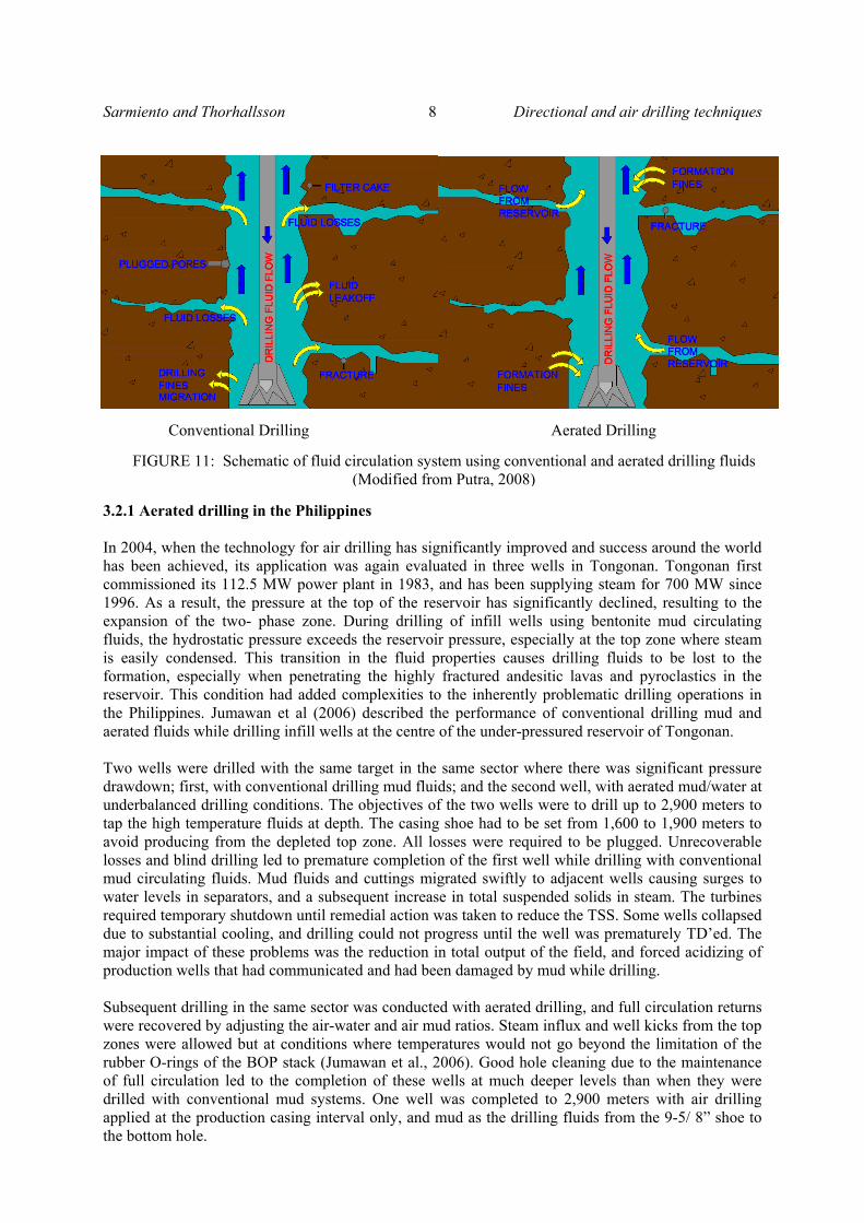
3.1 Performance drilling Aerated drilling is applied as part of a performance drilling management plan to reduce drilling costs by increasing the rate of penetration. This is achieved by the application of air, mist or foam drilling fluid systems to drill sub-hydrostatically. Air drilling in Iceland, New Zealand and Indonesia has been intended to increase penetration rate to shorten drilling time and save on rig rental and other third party services. With air drilling, differential sticking is avoided. By injecting high pressure air, stuck pipes are easily released. 3.2 Underbalanced reservoir drilling Here the wellbore pressure is intentionally designed and maintained below reservoir pressure to maintain fluid influx to the wellbore, thereby reducing formation damage. In conventional mud circulation system, hydrostatic pressure exceeds the reservoir pressure, resulting into loss of mud and cuttings into the permeable zone. The damage to formation, and sometimes, interference with other wells had justified the application of aerated drilling in the Philippines to address the make-up and infill well drilling requirement. Figure 11 shows the comparison of conventional mud and air drilling technique. Note that in conventional drilling, fluids are lost to the formation depending on the acceptance capacity of the loss zone. In cases of massive loss or total loss circulation (TLC), no fluids and cuttings return to the surface. Water is then used all the way for blind drilling. For the aerated drilling, the reverse process occurs. All the permeable zones intersected during drilling should have pressures higher than hydrostatic, thus, flows from these zones mixed with the aerated fluids flowing up to the surface. No mud or cuttings are supposed to invade the loss zone and thus damage to the formation is reduced if not eliminated. The application of aerated fluids for geothermal drilling in the Philippines was first attempted in Palinpinon geothermal field, where the water level was about 800 meters below the surface. At that time, problems associated with operator’s response to maintain air supply and control of pressure opposite an unexpected occurrence of loss zones and/or high pressure zone was not an integral part of the process and instrumentation. This was aggravated by the length of the air column to be maintained due to the deep water level in the wells. Then, there was no computer modelling software which would predict pressure profiles at depth. Moreover, there was lack of high compression capacity from the available compressor units. The two attempts therefore did not yield satisfactory results.
Sarmiento and Thorhallsson 8 Directional and air drilling techniques
3.2.1 Aerated drilling in the Philippines In 2004, when the technology for air drilling has significantly improved and success around the world has been achieved, its application was again evaluated in three wells in Tongonan. Tongonan first commissioned its 112.5 MW power plant in 1983, and has been supplying steam for 700 MW since 1996. As a result, the pressure at the top of the reservoir has significantly declined, resulting to the expansion of the two- phase zone. During drilling of infill wells using bentonite mud circulating fluids, the hydrostatic pressure exceeds the reservoir pressure, especially at the top zone where steam is easily condensed. This transition in the fluid properties causes drilling fluids to be lost to the formation, especially when penetrating the highly fractured andesitic lavas and pyroclastics in the reservoir. This condition had added complexities to the inherently problematic drilling operations in the Philippines. Jumawan et al (2006) described the performance of conventional drilling mud and aerated fluids while drilling infill wells at the centre of the under-pressured reservoir of Tongonan. Two wells were drilled with the same target in the same sector where there was significant pressure drawdown; first, with conventional drilling mud fluids; and the second well, with aerated mud/water at underbalanced drilling conditions. The objectives of the two wells were to drill up to 2,900 meters to tap the high temperature fluids at depth. The casing shoe had to be set from 1,600 to 1,900 meters to avoid producing from the depleted top zone. All losses were required to be plugged. Unrecoverable losses and blind drilling led to premature completion of the first well while drilling with conventional mud circulating fluids. Mud fluids and cuttings migrated swiftly to adjacent wells causing surges to water levels in separators, and a subsequent increase in total suspended solids in steam. The turbines required temporary shutdown until remedial action was taken to reduce the TSS. Some wells collapsed due to substantial cooling, and drilling could not progress until the well was prematurely TD’ed. The major impact of these problems was the reduction in total output of the field, and forced acidizing of production wells that had communicated and had been damaged by mud while drilling. Subsequent drilling in the same sector was conducted with aerated drilling, and full circulation returns were recovered by adjusting the air-water and air mud ratios. Steam influx and well kicks from the top zones were allowed but at conditions where temperatures would not go beyond the limitation of the rubber O-rings of the BOP stack (Jumawan et al., 2006). Good hole cleaning due to the maintenance of full circulation led to the completion of these wells at much deeper levels than when they were drilled with conventional mud systems. One well was completed to 2,900 meters with air drilling applied at the production casing interval only, and mud as the drilling fluids from the 9-5/ 8” shoe to the bottom hole.
FIGURE 11: Schematic of fluid circulation system using conventional and aerated drilling fluids (Modified from Putra, 2008)
Conventional Drilling Aerated Drilling

Directional and air drilling techniques 9 Sarmiento and Thorhallsson
3.2.2 Air Drilling Equipment and Layout Typical equipment used in the Philippines for aerated fluids geothermal drilling consist of the following: Three primary air compressors (1,500 cfm / 200 psig ); Two 1,500 psig two-stage air pressure boosters; One 1,500 psig flow meter; one 2,000 psi dry-flow recorder; one 50-500°F temperature recorder; One 1,500 psig single-acting triplex mist pump; Two 1,500 psig chemical injection pumps; One set of 2,000 standpipe manifold; One 500 psig geothermal rotating head; one banjo box or flow tee; One 10-in. emergency shut-down (ESD) valve; one 10-in. throttle valve; and One air/fluid/steam separator. Figure 12 is a schematic showing the well drilling assembly and the discharge line to the separator and the sump. Note the existence of the air and the fluid separator. 4. CONCLUSION Directional and air drilling techniques have been an integral part of the drilling operations of because of the numerous advantages gained by many geothermal operators. Compact development, where small land areas are developed instead of a distributed well pad location, has now been a common sight for geothermal installations because of directional drilling. Environmentally sensitive areas can be accessed with minimal impact to the environment because of the ability to drill wells outside or within the boundary. Directionally drilled relief well had been proven in the Philippines to kill an uncontrollable well. Side tracking is always an option when another leg in the wellbore is necessary to reach target depth. Air drilling has been applied worldwide because of the faster drilling results attained by developers. By avoiding mud damage to the formation, maximum production from wells are obtained without the need for acidizing. Underbalanced drilling has been proven to be very effective in dealing with under-pressured reservoir in the Philippines, thereby preventing interference with adjacent wells when drilling make-up and replacement wells.
FIGURE 12: Schematic of the wellhead assembly and surface piping set-up for aerated drilling in Iceland

Sarmiento and Thorhallsson 10 Directional and air drilling techniques
REFERENCES Budi Kesuma Adi Putra, I.M., 2008: Drilling practice with aerated drilling fluid. Indonesian and Icelandic geothermal fields. Report 11 in: Geothermal Training in Iceland 2008. UNU-GTP, Iceland, 77-100. Hole, H.M., 2008: Directional drilling of geothermal wells. Petroleum Engineering Summer School, Dubrovnik, Croatia. Workshop #26 June 9–13, 08. Jumawan, J.E., Saycon, R.D., Javier, R.A., and Gonzales, R.C., 2006: Underbalanced drilling application on PNOC wells. Proceedings 27th Annual PNOC EDC Geothermal Conference, Makati City, Philippines. March 8-9, 2006.