direct operated solenoid valves a · pdf file1 lapped spool & sleeve, direct operated...
TRANSCRIPT

DIRECT OPERATED SOLENOID VALVES
A SeriesMetal Seal, In-line Mounting/Sub-base Mounting

1
LAPPED SPOOL & SLEEVE, DIRECT OPERATED SOLENOID VALVES
A SeriesThe solenoid-operated air valves of this series are types metal seal and a spool valve.
This provides a choice of 3-way (3 ports), 4-way (5 ports), 3-position with single or double
solenoid, and 3-position with closed center or exhaust center models, in conformity with
customer's requirements.
High StrengthBody, solenoid cover and sub-base are of aluminum alloy castings of high strength.
Simple ConstructionExtreme simplification in construction design assures trouble-free valves and easy maintenance.
Small Size, light WeightLight weight and compact type makes installation easy.
Easy MaintenanceKURODA air valves are mounted on base, facilitating parts interchangeability without disturbing mounting or piping
connections.
●By plugging the unused ports, these valves can be utilized as normally open or normally closed 3-way or 2-wayvalves.
●Also usable as dual-pressure, 4-way or 3-way valves by piping two pressures into the exhaust ports, thusrendering the center port as a common exhaust.
Different pressures have no effect on the operation of this balanced spool valves.

2
FEATURES ―――――――――――――――――――――――――――――――――――――――P.1
INTRODACUTION OF KURODA CAD DATA LIBRARY ――――――――――――――――――――P.3
FOR SAFETY USE ――――――――――――――――――――――――――――――――――――P.4
SOLENOID VALVE/COMMON INSTRUCTIONS ―――――――――――――――――――――――P.5
3/5-PORT DIRECT OPERATED SOLENOID VALVE A06 series ――――――――――――――――P.9
3/5-PORT DIRECT OPERATED SOLENOID VALVE A08 series ――――――――――――――――P.12
3/5-PORT DIRECT OPERATED SOLENOID VALVE A10 series ――――――――――――――――P.15
3/5-PORT DIRECT OPERATED SOLENOID VALVE A15 series ――――――――――――――――P.18
INDIVIDUAL WIRING TYPE MANIFOLD MF○-C ――――――――――――――――――――――P.21
3-PORT DIRECT OPERATED SOLENOID VALVE SS231 ――――――――――――――――――P.26
INDIVIDUAL WIRING TYPE MANIFOLD MF○-TC/TI1 ――――――――――――――――――――P.28
CONTENTS
①Precision Lapped Spool and SleevePrecision lapped spool and sleeve are made of special heat-treated stainless steel, offering wear-resistance, corrosion-
resistance and the longest life guarantee.
②Large-sized TerminalThe terminal with spring washer is large enough to make wiring easier and prevent unsatisfactory contact. The clamping plate
moves up and down with the screw movement to speed wiring.
③Indicator Light (Optional)Indicator light can be incorporated upon request. The light gives visual indication of solenoid energization.
④Easily Replaceable Solenoid UnitThe solenoid and its cover are unified. Easily installed or replaced by loosening four captive screws. The highly dependable
solenoid is rated for continuous duty.
⑤Manual Piston SwitchManual piston switch permits manual operation of the valve with electrical power off.
⑥Locking button (Optional)Locking button can be mounted
⑦Bottom porting, Manifold Mounting are Available
① ③ ② ④
⑤⑥
⑦

3
http://www.kuroda-precision.co.jp/e-top
Access KURODA Home Page
FA Internet Service
Download Service
User Registration
Download
CD-ROM(CAD DATA LIBRARY)
CAD DATA LIBRARYLatest data is contained.
Customer
KURODA Sales Rep
KURODA Home Page Internet
http://www.kuroda-precision.co.jp/e-top
KURODA CAD DATA LIBRARY contains CAD data of pneumatic equipment, ball screws, support units andsingle-axis modules.In addition, various tools for selecting pneumatic equipment and ball screws are listed in it. Please use thislibrary to improve the design performance of your FA related equipment.
CAD Data Library is available from CD-ROM supplied by our company or our company's Home Page viaInternet. For a CD-ROM, please ask KURODA sales representative in charge of your company.
How to Obtain CAD Data Library
How to Download from Home Page CAD Data of Main Pneumatic Equipment①Pneumatic Actuators
Series of air cylinders and rotary actuators are listed inCAD DATA LIBRARY.
②Pneumatic Grippers/Vacuum EquipmentSeries of parallel grippers, rotary opening/closinggrippers, vacuum units and pads are listed in it.
③Control ValvesSeries of solenoid valves such as ADEX VALVEs arelisted in it.
④Other EquipmentSeries of speed controllers, joints, etc. are listed in it.⑤Air Cleaning Equipment
Series of FRL combination QUBE are listed in it.
Kind of CAD data
Type of data CD-ROM
○
○
Home Page
○*2○*2
DXF
DWG(AUTO CAD)*1
r12
r12
※1:Name of CAD software is our company's registered trademark.※2:Some of DWG type product data are not contained
(Note) CAD data is classified by each product and containedin a self-extracting exectable file format (.exe).
INTRODUCTION OF KURODA CAD DATA LIBRARY

FOR SAFETY USEBe sure to read the following instructions before use.For common and individual instructions, refer to the text of this catalogue.
Pneumatic fluid power-General rules relating to systems
4

5
SOLENOID VALVES/COMMON INSTRUCTIONS ①Be sure to read them before use.Also refer to Par. "For Safety Use" and instructions mentioned for each series of solenoid valves.
WARNINGStopping actuator at intermediate positionWhen stopping the actuator at an intermediate position using asolenoid valve listed in this catalogue, it is difficult to stop itaccurately because of the compressibility of air, unlike a hydrau-lic cylinder can dose.In addition, as the solenoid valve and air cylinder allow a certaindegree of air leak, they cannot stop at the fixed position for along period of time according to circumstances. When it isrequired to stop them at the fixed position for a long period oftime, contact KURODA.
Keeping pressure (including vacuum)As the solenoid valve is designed to allow a certain degree of airleak, it cannot be used to keep pressure (including vacuum) in apressure vessel etc.
Do not use for emergency shutoff valves.Solenoid valves listed in this catalogue are not designed for usein emergency shutoff valves and other safety applications.When using the solenoid valve for such applications, provide anindependent means to assure safety.
Exhausting residual airProvide a residual air exhausting function in due consideration ofmaintenance and inspection. Doing maintenance and inspectionwithout exhausting residual air may sometimes malfunction theactuator.When using a 3-position closed center type solenoid valve,compressed air is shut in between solenoid valve and actuatoreven if residual air from the air supply side to the solenoid valveis exhausted.Therefore, provide a means to exhaust the residual air pressureseparately.
Use in vacuumWhen using a solenoid valve for diverting vacuum and otherapplications, check specifications for the valve and select aproper one that can be used in vacuum.In order to prevent sucking foreign matters from the suction padand exhaust port, provide an inline filter between the suctionpad and solenoid valve and at the exhaust port.
Applying current continuously for long timeWhen using a solenoid valve while applying current to itcontinuously for a long period of time, contact KURODAbeforehand.
Avoid applying current simultaneously.When using a double-solenoid valve while applying current to itcontinuously for a long period of time, do not apply current toboth solenoids simultaneously ; otherwise the coil may be burntout or the main valve may malfunction.
Remodeling the solenoid valveDo not remodel the solenoid valve.
CAUTIONApplying current momentarilyWhen using a double-solenoid type valve, apply current for theprescribed period of time (0.1 sec.). If current is not applied forthe prescribed period of time, the solenoid valve may notperform the diverting action acording to circumstances.
Leak currentWhen a C-R element is used in the contact protective circuit(surge voltage protection), leak current will flow through the C-Relement.If this leak current becomes large, a malfunction will occur.Therefore, reduce leak current to less than 1 mA.
Use at low temperatureWhen using a solenoid valve at 5 ℃ or below, provide an airdryer or other proper means to prevent moisture from solidifyingor freezing.
Use with air blowWhen using a solenoid valve with air blow, select a direct-operated type or external pilot type solenoid valve.When an internal pilot type solenoid valve is used, it may notperform the diverting action due to a pressure drop at the timeof air blow.When an external pilot type solenoid valve is used, supplycompressed air within the specified pressure range to the pilotport.
Mounting position and directionA solenoid valve can be mounted in any position and directionas a general.However, a metal seal type double-solenoid valve and a 3-positionsolenoid valve should be mounted so that the spool may behorizontal.
Shock and vibrationReduce shocks and vibrations applied to the solenoid valve toless than the prescribed value. (refer to specifications.)Applying shocks and vibrations exceeding the prescribed valuemay result in a malfunction of the solenoid valve.
¡
¡
¡
¡
¡
¡
DESIGN
¡
¡
¡
¡
¡
¡
¡
¡
DESIGN
Contact
Solenoid
Leak current
C-R circuit
Power supply

6
SOLENOID VALVES/COMMON INSTRUCTIONS ②Be sure to read them before use.Also refer to Par. "For Safety Use" and instructions mentiond for each series of solenoid valves.
WARNINGRefer to specifications.Solenoid valves listed in this catalogue are designed forcompressed air. When using other fluid than compressed air,contact KURODA beforehand.Do not use a solenoid valve at pressure and temperatureoutside the range of specifications, otherwise resulting in abreakdown or malfunction.
WARNINGWhen mounting the solenoid valve, firmly fix it whileusing care to prevent the stationary part and jointfrom loosening.If the solenoid valve is mounted with insufficient strength, it maysometimes come off.
Do not start the system until it is ensured that equip-ment works properly.After mounting the solenoid valve, connect power supply andthen perform a functional test and a leak test. Check that it hasbeen correctly mounted and works properly, before starting thesystem.
Coating with paintWhen coating the resin portion with paint, it may be adverselyaffected by paint and solvent. For the propriety of painting,contact KURODA beforehand.Do not peel off the nameplate affixed on the solenoid valve anddo not erase or smear out the letter on it.
Provide space for maintenance and inspection.
CAUTIONFit an air muffler to the exhaust port (ports 3, 5) of thesolenoid valve.Dust or foreign matter that enters it may cause a malfunction ofthe solenoid valve.
Do not wipe off the model name inscribed on anameplate etc. with organic solvent.The inscribed indication may be erased.
CAUTIONBefore pipingThoroughly flush the inside of each pipe to remove chips,coolant, dust, etc. before piping.
How to wind a seal tapeWhen winding a seal tape around the threaded portion, leavespace of 1.5 to 2 thread turns.
How to apply liquid sealantWhen applying liquid sealant to the threaded portion, apply aproper amount to about 1/3 of the periphery of the threadedportion and then screw it.
Screw of pipe and jointWhen screwing the pipe and joint, use care to prevent chipsand sealant from entering the pipe and joint.Tighten them within a proper range of clamping torque.
Port size Clamping torque (N.m)
M3 0.3~ 0.5
M5 1.5~ 2.0
R, Rc1/8 7.0~ 9.0
R, Rc1/4 12.0~14.0
R, Rc3/8 2.0~24.0
R, Rc1/2 28.0~30.0
R, Rc3/4 28.0~30.0
R, Rc1 36.0~38.0
R, Rc11/4 40.0~42.0
R, Rc11/2 48.0~50.0
¡
¡
¡
¡
PIPING
¡
¡
¡
¡
¡
¡
MOUNTING
¡
SELECTION
When screwing, seal tape enters equipment, causing air leak.
(Good) (No good)
Leave space of 1.5 to 2 turns.
Joint Sealant Apply sealant to this portion.1/3
↓ ↓

7
SOLENOID VALVES/COMMON INSTRUCTIONS ③Be sure to read them before use.Also refer to Par. "For Safety Use" and instructions mentioned for each series of solenoid valves.
CAUTIONAvoid wrong piping.When connecting a pipe to a solenoid valve, be careful not tomistake the supply port by referring to the nameplate affixed tothe product or the product catalogue.
When using a 3-position closed center type solenoidvalve :Thoroughly check the piping between solenoid valve andactuator for air leak.
WARNINGWhen doing wiring work, be sure to turn off compressedair and power supplies beforehand.Wiring work without turning off air and power supplies maycause an electric shock or malfunction ; this sometimes resultsin an injury to the human body or a damage to property.
Avoid mis-wiring.Some solenoid valves have polarity : Those operating on DCwith built-in indicator light and those equipped with surgeprotective circuit.When wiring to a solenoid valve, check whether or not it haspolarity.For a solenoid valve having polarity, check the lead wire colorand symbol of the polarity by the catalogue or actual articlebeforehand and then make correct wiring.Mis-wiring will result in the following problems :(Where no polarity protective diode is incorporated :)Wiring to the wrong polarity will burn out the diode in thesolenoid valve, the switching element on the control unit side orthe power supply unit.(Where a polarity protective diode is provided :)Wiring to the wrong polarity will not cause the solenoid valve toperform a diverting action.
Avoid applying stress and tensile force to lead wirerepeatedly.Wiring made in such a manner that stress and tensile force arerepeatedly applied to the lead wire will result in the breaking ofwire. Provide some degree of margin for wiring.
Check that there is no insulation failure.If an insulation failure occurs in the lead wire connection,extension cable and terminal base, an excess flows to theswitching element of the solenoid valve or control unit,sometimes resulting in a damage.
Do not mistake applied voltage.Mistake in applied voltage in case of wiring to a solenoid valvewill cause an operation failure or burn out the coil.
After completion of wiring, check for wrongconnection before turning on power.
DANGERDo not use solenoid valve in a explosive environment.
WARNINGDo not use a solenoid valve in atmospheres containingcorrosive gases, chemicals, seawater, water and vaporand in places where a solenoid valve contacts thesematters.
Do not use a solenoid valve in a place where vibrationsor shocks are directly applied to it.
When a solenoid valve is exposed to the directsunlight, fit a protective cover to the solenoid valve.
When a solenoid valve is located around a heatsource, shut off the radiant heat.
When installing a solenoid valve in the control panel,take proper heat-radiating measures so that theinside temperature may be kept within the specifiedtemperature range.
When using a solenoid valve in a place where it isexposed to welding spatters, provide a protectivecover or other proper prevention.Welding spaters may burn out the plastic parts of the solenoidvalve, sometimes resulting in a fire.
CAUTIONSolenoid valves listed in this catalogue are non-lubrication.The non-lubricated solenoid valve can be used withoutlubrication, but can be used with lubrication.When using it with lubrication, do not discontinue supplying oil.Otherwise, the applied lubricant may run off, sometimesresulting in an operation failure.When using a lubricant, Class 1 turbine oil ISO VG 32 (con-tainning additive) is recommended.
¡
LUBRICATION
¡
¡
¡
¡
¡
¡
¡
OPERATING ENVIRONMENTS
¡
¡
¡
¡
¡
¡
WIRING
¡
¡
PIPING

8
SOLENOID VALVES/COMMON INSTRUCTIONS ④Be sure to read them before use.Also refer to Par. "For Safety Use" and instructions mentioned for each series of solenoid valves.
WARNINGUse pure air.Compressed air containing corrosive gases, chemicals, salt,etc. causes a breakdown or operation failure. So do not usesuch air.
CAUTIONFit an air filter with filtration of 5 µm or fine.
Install an air dryer.Compressed air containing much drainage causes the operationfailure of pneumatic equipment. Install an air dryer, lower thetemperature and reduce drainage.
Take proper countermeasures against sludge.If sludge produced in compressor oil enters pneumatic equip-ment, it will cause the operation failure of pneumatic equipment.It is recommendable to use compressor oil (NISSEKI FAIRCALLA68, IDEMITSU DAPHUNY SUPER CS68) featuring minimizedsludge production or use a sludge filter or mist cleaner toprevent sludge from entering the pneumatic equipment.
WARNINGInspection before maintenanceFirst check that load drop prevention has been provided.Then shut off air and power supplies to the system and exhaustresidual air in the system beforehand.For a 3-position closed center type solenoid valve, compressedair is sealed between solenoid valve and cylinder.Exhaust this residual compressed air.
Inspection after maintenanceWhen restarting the system, check that preventive measuresagainst flying-out of the actuator have been taken. Thenconnect compressed air supply to the pneumatic system, andperform a proper functional test and a leak test to check that itworks safely without fail, before starting the system.
Operation at low frequencyTo prevent an operation failure, perform the switching action ofthe solenoid valve once per 30 days. (Be careful of air supply.)
Manual operationWhen the solenoid valve is manually operated, the systemconnected to it is also operated. Make sure safety beforeoperation.
Disassembly of solenoid valveWhen disassembling the solenoid valve, contact KURODAbeforehand.
CAUTIONDrainingTo keep the quality of air to a certain level, drain the air filter atperiodical intervals.
¡
¡
¡
¡
¡
¡
MAINTENANCE AND INSPECTION
¡
¡
¡
¡
QUALITY OF AIR
Filter Sludge filterMist cleaner
Regulator

AS2306AS2406AD2406AD3406ADE3406
2-positionSingle solenoid
2-positionSingle solenoid
2-positionDouble solenoid
3-positionClosed center
3-positionExhaust center
Model No.
Fluid
Port size
Effective area
Cv value
Operating ambient temperature
Operating pressure range
Maximum frequency
Unit
mm2
˚C
MPa
Cycle/min
Non-lubricated/lubricated air
Rc! / 8、! / 4
9
0.49
600 600 600 360 360
10
0.54 0.54 0.49 0.49
10 9 9
-5~60
-0.1~1
AC100、200、110、220
JIS grade B
±10
50/60
13
8.5
37
32
13
8.5
43
39.5
s
(Average)
V
%
Hz
VA
VA
VA
VA
kg
AS2306 AS2406 AD2406 AD3406 ADE3406
0.34 0.47 0.66 0.68 0.68
0.012 0.013 0.012 0.015 0.015Response time
(at 0.5MPa)
Powerconsumption
Holding50Hz
60Hz
50Hz
60HzInlush
Rated voltage
Grade of insulation
Permissible voltage fluctuation
Rated frequency
Mass
SPECIFICATIONS
(Note)・When temperature of valve site gose down below 5 ℃, complete dry air shall be supplied to prevent from freezing.・Effective area shown above is value between ports 1 and 2, 4.・Response time shown above is in accordance with JIS B 8375.
9
3/5-PORT DIRECT OPERATED SOLENOID VALVES
A06 SeriesMetal Seal, In-line mounting/Sub-base Mounting type

ORDERING INSTRUCTION
OPTIONAL PARTS AND SPARE PARTS
AS2306
AS2406
AD2406
AD3406
ADE3406
10002 ——
③②
AS2406
①
①Function ②Port size
0102
Rc! / 8Rc! / 4
③Voltage
100110200220
AC100VAC110VAC200VAC220V
Parts Name
Solenoid
Sub-base
Base gasket
Spring
AC 100V
AC 110V
AC 200V
AC 220V
Rc! / 8
Rc! / 4
For 2-position
For 3-position
Model No.
A06-103
A06-10310
A06-203
A06-20320
A06-SB-01
A06-SB-02
A06-G
A06-SS
A06-3S
10
A06 Series

DIMENSIONSAS2306 AS2406(Unit:mm)
AD2406 (Unit:mm)
AD3406、ADE3406 (Unit:mm)
Bottom porting (Unit:mm)
(Unit:mm)
Port size:Rc1/8Bottom porting is made to order
Lead wire length 500
Lead wire length 510
Lead wire length 510
Port 1
Port 3 Port 4Port 2
Port 5
Lead wirelength 545
11
A06 Series

Model No.
Fluid
Port size
Effective area
Cv value
Operating ambient temperature
Operating pressure range
Maximum frequency
Unit
mm2
˚C
MPa
Cycle/min
s
(Average)
V
%
Hz
VA
VA
VA
VA
kg
Response time
(at 0.5MPa)
Powerconsumption
Holding50Hz
60Hz
50Hz
60HzInlush
Rated voltage
Grade of insulation
Permissible voltage fluctuation
Rated frequency
Mass
SPECIFICATIONS
(Note)・When temperature of valve site gose down below 5 ℃, complete dry air shall be supplied to prevent from freezing.・Effective area shown above is value between ports 1 and 2, 4.・Response time shown above is in accordance with JIS B 8375.
AS2308AS2408AD2408AD3408ADE3408
2-positionSingle solenoid
2-positionSingle solenoid
2-positionDouble solenoid
3-positionClosed center
3-positionExhaust center
Non-lubricated/lubricated air
Rc! / 4、# / 8
22
1.19
400 400 400 250 250
30
1.63 1.63 1.36 1.36
30 25 25
-5~60
-0.1~1
AC100、200、110、220
JIS grade B
±10
50/60
25
14
130
110
25
14
170
140
AS2308 AD2408 AD3408 ADE3408AS2408
0.7 1.0 1.4 1.5 1.5
0.013 0.015 0.01 0.015 0.015
12
3/5-PORT DIRECT OPERATED SOLENOID VALVES
A08 SeriesMetal Seal, In-line mounting/Sub-base Mounting type

ORDERING INSTRUCTION
OPTIONAL PARTS AND SPARE PARTS
AS2308
AS2408
AD2408
AD3408
ADE3408
100AS2408 P02 ——
③ ④②①
①Function ②Port size
0203
Rc! / 4Rc# / 8
③Voltage
100110200220
AC100VAC110VAC200VAC220V
④Versions
No markIKP
StandardWith indicator lightWith surge suppressorWith indicator light & surge suppressor
Parts Name
Solenoid unit
for 2-position
Solenoid unit
for 3-position
Sub-base
Base gasket
Spring
AC 100V
AC 110V
AC 200V
AC 220V
AC 100V
AC 110V
AC 200V
AC 220V
Rc! / 4
Rc# / 8
For 2-position
For 3-position
Model No.
A08-105
A08-10510
A08-205
A08-20520
A08-109
A08-10910
A08-209
A08-20920
A08-SB-02
A08-SB-03
A08-G
A08-SS
A08-3S
13
A08 Series

DIMENSIONSAS2308 AS2408(Unit: mm)
(Unit: mm)AD2408
(Unit: mm)Bottom porting
(Unit: mm)AD3408、 ADE3408
(Unit: mm)
※ Bottom porting is made to order
Port size: Rc ! / 4
Port 2
Port 3
Port 4Port 5
Port 1
14
A08 Series

Model No.
Fluid
Port size
Effective area
Cv value
Operating ambient temperature
Operating pressure range
Maximum frequency
Unit
mm2
˚C
MPa
Cycle/min
s
(Average)
V
%
Hz
VA
VA
VA
VA
kg
Response time
(at 0.5MPa)
Powerconsumption
Holding50Hz
60Hz
50Hz
60HzInlush
Rated voltage
Grade of insulation
Permissible voltage fluctuation
Rated frequency
Mass
SPECIFICATIONS
(Note)・When temperature of valve site gose down below 5 ℃, complete dry air shall be supplied to prevent from freezing.・Effective area shown above is value between ports 1 and 2, 4.・Response time shown above is in accordance with JIS B 8375.
AS2310AS2410AD2410AD3410ADE3410
2-positionSingle solenoid
2-positionSingle solenoid
2-positionDouble solenoid
3-positionClosed center
3-positionExhaust center
Rc! / 4、# / 8、! / 2
Non-lubricated/lubricated air
Rc# / 8、! / 2
38
2.06
350 350 350 200 200
50
2.71 2.71 2.71 2.71
50 50 50
-5~60
-0.1~1
AC100、200、110、220
JIS grade B
±10
50/60
36
27
290
250
36
27
430
360
AS2310 AS2410 AD2410 AD3410 ADE3410
1.3 1.9 2.7 2.9 2.9
0.016 0.02 0.015 0.015 0.015
15
3/5-PORT DIRECT OPERATED SOLENOID VALVES
A10 SeriesMetal Seal, In-line mounting/Sub-base Mounting type

ORDERING INSTRUCTION
AS2310
AS2410
AD2410
AD3410
ADE3410
100AS2410 P03 ——
③ ④②①
①Function ②Port size
020304
Rc! / 4Rc# / 8Rc! / 2
③Voltage
100110200220
AC100VAC110VAC200VAC220V
④Versions
No markIKP
StandardWith indicator lightWith surge suppressorWith indicator light & surge suppressor
OPTIONAL PARTS AND SPARE PARTSParts Name
Solenoid unit
for 2-position
Solenoid unit
for 3-position
Sub-base
Base gasket
Spring
AC 100V
AC 110V
AC 200V
AC 220V
AC 100V
AC 110V
AC 200V
AC 220V
Rc! / 4
Rc# / 8
Rc! / 2
For 2-position
For 3-position
Model No.
A10-106
A10-10610
A10-206
A10-20620
A10-113
A10-11310
A10-213
A10-21320
A10-SB-02
A10-SB-03
A10-SB-04
A10-G
A10-SS
A10-3S
16
A10 Series

DIMENSIONSAS2310 AS2410(Unit:mm)
(Unit:mm)AD2410
(Unit:mm)Bottom porting
(Unit:mm)AD3410、ADE3410
(Unit:mm)
※Bottom porting is made to order
Port size:Rc! / 4、# / 8
Port 4 Port 2
Port 5
Port 3
Port 1
17
A10 Series

75 75
AS2315AS2415AD2415AD3415ADE3415
2-positionSingle solenoid
2-positionSingle solenoid
2-positionDouble solenoid
3-positionClosed center
3-positionExhaust center
Non-lubricated/lubricated air
Rc! / 2、# / 4
80
4.34
150 150 150 150 150
75
4.07 4.07 4.07 4.07
75
-5~60
-0.1~1
AC100、200、110、220
JIS grade B
±10
50/60
38
28
370
320
38
28
520
480
AS2315 AD2415 AD3415 ADE3415AS2415
1.8 2.8(3.2) 3.6(4.0) 3.8(4.2) 3.8(4.2)
0.018 0.035 0.025 0.020 0.020
Model No.
Fluid
Port size
Effective area
Cv value
Operating ambient temperature
Operating pressure range
Maximum frequency
Unit
mm2
˚C
MPa
Cycle/min
s
(Average)
V
%
Hz
VA
VA
VA
VA
kg
Response time
(at 0.5MPa)
Powerconsumption
Holding50Hz
60Hz
50Hz
60HzInlush
Rated voltage
Grade of insulation
Permissible voltage fluctuation
Rated frequency
Mass
SPECIFICATIONS
(Note)・When temperature of valve site gose down below 5 ℃, complete dry air shall be supplied to prevent from freezing.・Effective area shown above is value between ports 1 and 2, 4.・Response time shown above is in accordance with JIS B 8375.・Mass in bracket( )shown with Rc# / 4 ported sub-base.
18
3/5-PORT DIRECT OPERATED SOLENOID VALVES
A15 SeriesMetal Seal, In-line mounting/Sub-base Mounting type

ORDERING INSTRUCTION
AS2315
AS2415
AD2415
AD3415
ADE3415
100AS2415 P04 ——
③ ④②①
①Function ②Port size
0406
Rc! / 2Rc# / 4
③Voltage
100110200220
AC100VAC110VAC200VAC220V
Model No.
A15-107
A15-10710
A15-207
A15-20720
A15-115
A15-11510
A15-215
A15-21520
A15-SB-04
A15-SB-06
A15-G
A15-SS
A15-3S
④Versions
No markIKP
StandardWith indicator lightWith surge suppressorWith indicator light & surge suppressor
OPTIONAL PARTS AND SPARE PARTSParts Name
Solenoid unit
for 2-position
Solenoid unit
for 3-position
Sub-base
Base gasket
Spring
AC 100V
AC 110V
AC 200V
AC 220V
AC 100V
AC 110V
AC 200V
AC 220V
Rc! / 2
Rc# / 4
For 2-position
For 3-position
19
A15 Series

DIMENSIONSAS2315 AS2415(Unit:mm)
(Unit:mm)AD2415
(Unit:mm)(Note) Dimensions in bracket( )shown with Rc# / 4 ported sub-base.Bottom porting
(Unit:mm)AD3415、ADE3415
(Unit:mm)
※Bottom porting is made to order
Port size:Rc! / 2
Port 4 Port 2
Port 5
Port 3Port 1
20
A15 Series

MF□ーCC
MF□ーCI
Common SUP, Common EXH
Ports 2 & 4 on side
Common SUP, Individual EXH
Ports 2 & 4 on side
Type of manifold
Number of stations
Mountable solenoid valve
Blank plate
Port size
Port 1
Port 3, 5
Port 2, 4
MF□-CC06
Common SUP, common EXH
Rc! / 4
Rc! / 4
Rc! / 8、! / 4
2~20
AS2406-NBAD2406-NBAD3406-NBADE3406-NB
CC06-BP
MF□-CC08
Common SUP, common EXH
Rc# / 8
Rc# / 8
Rc! / 4、# / 8
2~20
AS2408-NBAD2408-NBAD3408-NBADE3408-NB
CC08-BP
MF□-CC10
Common SUP, common EXH
Rc! / 2
Rc! / 2
Rc# / 8、! / 2
2~20
AS2410-NBAD2410-NBAD3410-NBADE3410-NB
CC10-BP
MF□-CC15
Common SUP, common EXH
Rc# / 4
Rc# / 4
Rc! / 2
2~20
AS2415-NBAD2415-NBAD3415-NBADE3415-NB
CC15-BP
Type of manifold
Number of stations
Mountable solenoid valve
Blank plate
Port size
Port 1
Port 3, 5
Port 2, 4
MF□-CI06
Common SUP, individual EXH
Rc! / 4
Rc! / 8
Rc! / 8、! / 4
2~20
AS2406-NBAD2406-NBAD3406-NBADE3406-NB
CC06-BP
MF□-CI08
Common SUP, individual EXH
Rc# / 8
Rc! / 4、# / 8
Rc! / 4、# / 8
2~20
AS2408-NBAD2408-NBAD3408-NBADE3408-NB
CC08-BP
MF□-CI10
Common SUP, individual EXH
Rc! / 2
Rc# / 8、! / 2
Rc# / 8、! / 2
2~20
AS2410-NBAD2410-NBAD3410-NBADE3410-NB
CC10-BP
MF□-CI15
Common SUP, cindividual EXH
Rc# / 4
Rc! / 2
Rc! / 2
2~20
AS2415-NBAD2415-NBAD3415-NBADE3415-NB
CC15-BP
MANIFOLD SPECIFICATIONS
21
INDIVIDUAL WIRING TYPE MANIFOLD
MF○-CSeparate type

ORDERING INSTRUCTION
02— —
④
CC 08
② ③
MF 5
①
AS2408 100 PNB ——
④③②①
①Number of stations
2:20
2 station:
20station
③Mountable solenoid valve
06081015
A06 seriesA08 seriesA10 seriesA15 series
④Size of ports 2 and 4
01020304
Rc! / 8Rc! / 4Rc# / 8Rc! / 2
②Type of manifold
CCCI
Common SUP, common EXHCommon SUP, individual EXH
Manifold
Mountable solenoid valve (For details refer to Pages 9 to 20.)
①Function
・List solenoid valves to be mounted.
・When mounting solenoid valves of different type, specify the type and quantity of solenoid valves from port 1 side.
・When ordering a solenoid valve of special specifications, refer to“Specification for Manifold”which is separately available.
(Example)MF5-CC08-02 1 pc.AS2408-NB-100 2 pcs.AD2408-NB-100 2 pcs.CC08-BP 1 pc.
HOW TO ORDER
AS24
AD24
AD34
ADE34
②Port size
NB Without sub-base
③Voltage
100110200220
AC100VAC110VAC200VAC220V
④Versions
No markIKP
StandardWith indicator lightWith surge suppressorWith indicator light & surge suppressor
22
A Series

DIMENSIONSMF□-CC06
MF□-CI06
(Unit: mm)
(Unit: mm)
Specifications for connection
Specifications for connection
4-φ7.4 Mounting hole
4-φ7.4 Mounting hole
Bottom porting
4-φ7.4 Mounting hole
Bottom porting
4-φ7.4 Mounting hole
23
A Series
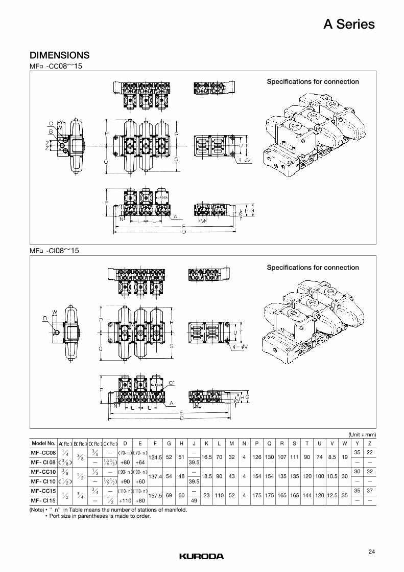
DIMENSIONSMF□-CC08~15
MF□-CI08~15
Specifications for connection
Specifications for connection
(Unit:mm)
Model No.
MF-CC08
MF- CI 08
MF-CC10
MF- CI 10
MF-CC15
MF- CI 15
A(Rc)
! / 4
(# / 8)
# / 8
(! / 2)
! / 2
# / 8
! / 2
# / 4
# / 8
-
! / 2
-
# / 4
-
-
! / 4(# / 8)
-
# / 8(! / 2)
-
! / 2
(70×n)
+80
(90×n)
+90
(110×n)
+110
(70×n)
+64
(90×n)
+60
(110×n)
+80
124.5
137.4
157.5
52
54
69
51
48
60
-
39.5
-
39.5
-
49
16.5
18.5
23
70
90
110
32
43
52
4
4
4
126
154
175
130
154
175
107
135
165
111
135
165
90
120
144
74
100
120
8.5
10.5
12.5
19
30
35
35
-
30
-
35
-
22
-
32
-
37
-
B(Rc)C(Rc)C'(Rc) D E F G H J K L M N P Q R S T U V W Y Z
(Note)・“n”in Table means the number of stations of manifold.・Port size in parentheses is made to order.
24
A Series

BOTTOM OF MANIFOLD PORTED (Custom-made)
ADAPTORUsed to connect a manifold of different size.
(Unit:mm)
(Unit:mm)
Model No.
Model No.
Applicable manifoldMF-C□06MF-C□08
24
MF-C□08MF-C□10
30
MF-C□10MF-C□15
40X
MFA-C0608 MFA-C0810 MFA-C1015
Port size A B K J H
Rc! / 4、# / 8
Rc# / 8、! / 2
Rc! / 2、# / 4
90
120
144
70
90
110
20
25
30
28
34
45
12
17
22.5
MF□- 08
MF□- 10
MF□- 15
CCC I
CCC I
CCC I
25
A Series

Model No.
Fluid
Port size
Effective area
Cv value
Operating ambient temperature
Operating pressure range
Maximum frequency
Response time(at 0.5MPa)
Unit
mm2
˚C
MPa
Cycle/min
s
V
%
Hz
VA
VA
VA
VA
W
kg
SS231
Non-lubricated/lubricated air
M5、Rc! / 8
0.6
0.03
-5~60
0~1
1200
ON 0.006、OFF0.008
AC100/110、200/220、DC24
JIS grade B
±10(DC )
50/60
3.2
2.6
5.5
4.5
2.5
0.08
+10-15
Rated voltage
Grade of insulation
Po
wer
cons
ump
tion
AC
Holding
Inlush
50Hz
60Hz
50Hz
60Hz
Permissible voltage fluctuation
Rated frequency
Power consumption DC
Mass
SPECIFICATIONS
(Note)・When temperature of valve site gose down below 5 ℃, complete dryair shall be supplied to prevent from freezing.
(Note)・Effective area shown above is value between ports 1 and 2.(Note)・Response time shown above is in accordance with JIS B 8375.
SS231 2-positionSingle solenoid
JIS Symbol
ORDERING INSTRUCTION
100 G LSS231 M5 ——
② ③ ④①
①Port size
NBM501
Without sub-baseM5×0.8Rc! / 8
③Wiring
LGC
*GK*CKD
Lead wireGromment with terminalConduit with terminalGromment with surge suppressorConduit with surge suppressorDIN connector
*:Made to order
②Voltage
100200D24
AC100V/110VAC200V/220VDC24V
④Option
No markL
Without option (Standard)With locking button
26
3-PORT DIRECT OPERATED SOLENOID VALVES
SS231Poppet Seal/Sub-base Mounting type

(Unit: mm)CONSTRUCTION AND MAIN PARTS DIMENSIONS
No. Description
①
②
③
④
⑤
⑥
⑦
⑧
⑨
Body
Plunger
Spring
Coil
Manual ring
Manual override
Cover
O-ring
Sub-base
Type LLead wire length 500
Type C
Type G
2-M3×0.5 depth5
27
SS231

ORDERING INSTRUCTIONS
MANIFOLD SPECIFICATIONS
M5— —
③
TI 1
②
MF 5
①
100 GSS231 LMF — ——
③ ④②①
①Number of stations
2:10
2 station:
10 station
③Size of port 2
M501
M5×0.8Rc! / 8
②Type of manifold
TITC
Common SUP, Indvidual EXHCommon SUP, Common EXH
Manifold Mountable solenoid valve
List solenoid valves to be mounted.
(Example)
MF5-TC1-M5 1 pc.SS231-MF-100G 5 pcs.
HOW TO ORDER
MF□-TI1MF□-TC1
Common SUP, Indvidual EXH
Port 2 on side
Common SUP, Common EXH
Port 2 on side
①Type of solenoid valve
NBMF
For TIFor TC
②Voltage
100200D24
AC100V/110VAC200V/220VDC24V
④Option
No markL
Without option (Standard)With locking button
Type of manifoldMF□-TI1-M5
Common SUP, Indvidual EXH
M5
-
M5
2~10
Rc! / 8
-
Rc! / 8
2~10
M5
M5
M5
2~10
Rc! / 8
Rc! / 8
Rc! / 8
2~10
SS231-NB SS231-MF
MF□-TI1-01
Common SUP, Indvidual EXH
MF□-TC1-M5
Common SUP, Common EXH
MF□-TC1-01
Common SUP, Common EXH
Port size
Port 1
Port 3
Port 2
Number of stations
Mountable solenoid valve
③Wiring
LGC
*GK*CKD
Lead wireGromment with terminalConduit with terminalGromment with surge suppressorConduit with surge suppressorDIN connector
*:Made to order
28
INDIVIDUAL WIRING TYPE MANIFOLD
MF○- 1Bar type
T ITC

DMENSIONSMF□-TI1-01
MF□-TI1-M5
(Unit:mm)
(Unit:mm)
Specifications for connection
Specifications for connection
●Port 1:Left side on dimensional drawing
Port size Rc! / 8●Port 2:Front side on dimensional drawing
Port size Rc! / 8
●Port 1:Left side on dimensional drawing
Port size M5
●Port 2:Front side on dimensional drawing
Port size M5
n:Number of stations
n:Number of stations
29
SS231

DMENSIONSMF□-TC1-01 (Made to order)
MF□-TC1-M5 (Made to order) (Unit:mm)
Specifications for connection
Specifications for connection
●Port 1:Left side on dimensional drawing
Port size Rc! / 8●Port 2:Front side on dimensional drawing
Port size Rc! / 8●Port 3:Right side on dimensional drawing
Port size Rc! / 8
●Port 1:Left side on dimensional drawing
Port size M5
●Port 2:Front side on dimensional drawing
Port size M5
●Port 3:Right side on dimensional drawing
Port size M5
n:Number of stations
n:Number of stations
(Unit:mm)
30
SS231
CAT. NO.KA192-○b

PILOT OPERATED SOLENOID VALVES
PC RC06,08,15 SeriesRubber Seal, Sub-base Mounting

1
RUBBER SEAL, PILOT OPERATED SOLENOID VALVES
PC/RC06, 08, 15 series
●High flow from compact die casted body.
●Single piece spool with patented TS seal rings featuring wear compensation
design for long life.
●Unique solenoid design minimizes burn-out and power consumption.
●4-way, 4/5-port, 2/3-position valves, In-line, Sub-base and manifold.
●Manual override (None locking type) is standard on all PC/RC series.
Locking type is available on request.

2
Mounting●Sub-base type
●With mounting bracket
●In-line type
●MFB□□-PC06
●MFU□□-RC06
●MFS□□-PC06
●MF□□-PC08 ●MF□□-PC15
●MFU□□-RC08
●MFS□□-PC08
Manifold
Model No.PCS24※※
Wiring●Lead wire
●Grommet with terminal
●Conduit with terminal●DIN connector
Voltage●AC100/110V
●AC200/220V
●DC24V
Option & Special specifications●With surge suppressor
●With locking override
●External pilot
RCS24※※
PCD24※※ RCD24※※
PCD34※※ RCD34※※
PCE34※※ RCE34※
PCO34※※ RCO34※※
FEATURES―――――――――――――――――――――――――――――――――P.1VARIATION―――――――――――――――――――――――――――――――――P.2INTRODUCTION OF KURODA CAD DATA LIBRARY―――――――――――――――P.3FOR SAFETY USE――――――――――――――――――――――――――――――P.4SOLENOID VALVE/COMMON INSTRUCTIONS―――――――――――――――――P.5PC/RC06, 08,15 series/INDIVIDUAL INSTRUCTIONS―――――――――――――――P.95 PORT PAILOT OPERATED SOLENOID VALVE PC06 series――――――――――P.11INDIVIDUAL WIRING TYPE MANIFOLD MF○-PC06―――――――――――――――P.155 PORT PAILOT OPERATED SOLENOID VALVE PC08 series――――――――――P.18INDIVIDUAL WIRING TYPE MANIFOLD MF○-PC08―――――――――――――――P.225 PORT PAILOT OPERATED SOLENOID VALVE PC15 series――――――――――P.25INDIVIDUAL WIRING TYPE MANIFOLD MF○-PC15―――――――――――――――P.295 PORT PAILOT OPERATED SOLENOID VALVE RC06 series――――――――――P.32INDIVIDUAL WIRING TYPE MANIFOLD MF○-RC06―――――――――――――――P.365 PORT PAILOT OPERATED SOLENOID VALVE RC08 series――――――――――P.39INDIVIDUAL WIRING TYPE MANIFOLD MF○-RC08 ――――――――――――――P.43
CONTENTS
VARIATIONS

3
http://www.kuroda-precision.co.jp/e-top
Access KURODA Home Page
FA Internet Service
Download Service
User Registration
Download
CD-ROM(CAD DATA LIBRARY)
CAD DATA LIBRARYLatest data is contained.
Customer
KURODA Sales Rep
KURODA Home Page Internet
http://www.kuroda-precision.co.jp/e-top
KURODA CAD DATA LIBRARY contains CAD data of pneumatic equipment, ball screws, support units andsingle-axis modules.In addition, various tools for selecting pneumatic equipment and ball screws are listed in it. Please use thislibrary to improve the design performance of your FA related equipment.
CAD Data Library is available from CD-ROM supplied by our company or our company's Home Page viaInternet. For a CD-ROM, please ask KURODA sales representative in charge of your company.
How to Obtain CAD Data Library
How to Download from Home Page CAD Data of Main Pneumatic Equipment①Pneumatic Actuators
Series of air cylinders and rotary actuators are listed inCAD DATA LIBRARY.
②Pneumatic Grippers/Vacuum EquipmentSeries of parallel grippers, rotary opening/closinggrippers, vacuum units and pads are listed in it.
③Control ValvesSeries of solenoid valves such as ADEX VALVEs arelisted in it.
④Other EquipmentSeries of speed controllers, joints, etc. are listed in it.⑤Air Cleaning Equipment
Series of FRL combination QUBE are listed in it.
Kind of CAD data
Type of data CD-ROM
○
○
Home Page
○*2○*2
DXF
DWG(AUTO CAD)*1
r12
r12
※1:Name of CAD software is our company's registered trademark.※2:Some of DWG type product data are not contained
(Note) CAD data is classified by each product and containedin a self-extracting exectable file format (.exe).
INTRODUCTION OF KURODA CAD DATA LIBRARY

FOR SAFETY USEBe sure to read the following instructions before use.For common and individual instructions, refer to the text of this catalogue.
Pneumatic fluid power-General rules relating to systems
4

5
SOLENOID VALVES/COMMON INSTRUCTIONS ①Be sure to read them before use.Also refer to Par. "For Safety Use" and instructions mentioned for each series of solenoid valves.
WARNINGStopping actuator at intermediate positionWhen stopping the actuator at an intermediate position using asolenoid valve listed in this catalogue, it is difficult to stop itaccurately because of the compressibility of air, unlike a hydrau-lic cylinder can dose.In addition, as the solenoid valve and air cylinder allow a certaindegree of air leak, they cannot stop at the fixed position for along period of time according to circumstances. When it isrequired to stop them at the fixed position for a long period oftime, contact KURODA.
Keeping pressure (including vacuum)As the solenoid valve is designed to allow a certain degree of airleak, it cannot be used to keep pressure (including vacuum) in apressure vessel etc.
Do not use for emergency shutoff valves.Solenoid valves listed in this catalogue are not designed for usein emergency shutoff valves and other safety applications.When using the solenoid valve for such applications, provide anindependent means to assure safety.
Exhausting residual airProvide a residual air exhausting function in due consideration ofmaintenance and inspection. Doing maintenance and inspectionwithout exhausting residual air may sometimes malfunction theactuator.When using a 3-position closed center type solenoid valve,compressed air is shut in between solenoid valve and actuatoreven if residual air from the air supply side to the solenoid valveis exhausted.Therefore, provide a means to exhaust the residual air pressureseparately.
Use in vacuumWhen using a solenoid valve for diverting vacuum and otherapplications, check specifications for the valve and select aproper one that can be used in vacuum.In order to prevent sucking foreign matters from the suction padand exhaust port, provide an inline filter between the suctionpad and solenoid valve and at the exhaust port.
Applying current continuously for long timeWhen using a solenoid valve while applying current to itcontinuously for a long period of time, contact KURODAbeforehand.
Avoid applying current simultaneously.When using a double-solenoid valve while applying current to itcontinuously for a long period of time, do not apply current toboth solenoids simultaneously ; otherwise the coil may be burntout or the main valve may malfunction.
Remodeling the solenoid valveDo not remodel the solenoid valve.
CAUTIONApplying current momentarilyWhen using a double-solenoid type valve, apply current for theprescribed period of time (0.1 sec.). If current is not applied forthe prescribed period of time, the solenoid valve may notperform the diverting action acording to circumstances.
Leak currentWhen a C-R element is used in the contact protective circuit(surge voltage protection), leak current will flow through the C-Relement.If this leak current becomes large, a malfunction will occur.Therefore, reduce leak current to less than 1 mA.
Use at low temperatureWhen using a solenoid valve at 5 ℃ or below, provide an airdryer or other proper means to prevent moisture from solidifyingor freezing.
Use with air blowWhen using a solenoid valve with air blow, select a direct-operated type or external pilot type solenoid valve.When an internal pilot type solenoid valve is used, it may notperform the diverting action due to a pressure drop at the timeof air blow.When an external pilot type solenoid valve is used, supplycompressed air within the specified pressure range to the pilotport.
Mounting position and directionA solenoid valve can be mounted in any position and directionas a general.However, a metal seal type double-solenoid valve and a 3-positionsolenoid valve should be mounted so that the spool may behorizontal.
Shock and vibrationReduce shocks and vibrations applied to the solenoid valve toless than the prescribed value. (refer to specifications.)Applying shocks and vibrations exceeding the prescribed valuemay result in a malfunction of the solenoid valve.
¡
¡
¡
¡
¡
¡
DESIGN
¡
¡
¡
¡
¡
¡
¡
¡
DESIGN
Contact
Solenoid
Leak current
C-R circuit
Power supply

6
SOLENOID VALVES/COMMON INSTRUCTIONS ②Be sure to read them before use.Also refer to Par. "For Safety Use" and instructions mentiond for each series of solenoid valves.
WARNINGRefer to specifications.Solenoid valves listed in this catalogue are designed forcompressed air. When using other fluid than compressed air,contact KURODA beforehand.Do not use a solenoid valve at pressure and temperatureoutside the range of specifications, otherwise resulting in abreakdown or malfunction.
WARNINGWhen mounting the solenoid valve, firmly fix it whileusing care to prevent the stationary part and jointfrom loosening.If the solenoid valve is mounted with insufficient strength, it maysometimes come off.
Do not start the system until it is ensured that equip-ment works properly.After mounting the solenoid valve, connect power supply andthen perform a functional test and a leak test. Check that it hasbeen correctly mounted and works properly, before starting thesystem.
Coating with paintWhen coating the resin portion with paint, it may be adverselyaffected by paint and solvent. For the propriety of painting,contact KURODA beforehand.Do not peel off the nameplate affixed on the solenoid valve anddo not erase or smear out the letter on it.
Provide space for maintenance and inspection.
CAUTIONFit an air muffler to the exhaust port (ports 3, 5) of thesolenoid valve.Dust or foreign matter that enters it may cause a malfunction ofthe solenoid valve.
Do not wipe off the model name inscribed on anameplate etc. with organic solvent.The inscribed indication may be erased.
CAUTIONBefore pipingThoroughly flush the inside of each pipe to remove chips,coolant, dust, etc. before piping.
How to wind a seal tapeWhen winding a seal tape around the threaded portion, leavespace of 1.5 to 2 thread turns.
How to apply liquid sealantWhen applying liquid sealant to the threaded portion, apply aproper amount to about 1/3 of the periphery of the threadedportion and then screw it.
Screw of pipe and jointWhen screwing the pipe and joint, use care to prevent chipsand sealant from entering the pipe and joint.Tighten them within a proper range of clamping torque.
Port size Clamping torque (N.m)
M3 0.3~ 0.5
M5 1.5~ 2.0
R, Rc1/8 7.0~ 9.0
R, Rc1/4 12.0~14.0
R, Rc3/8 2.0~24.0
R, Rc1/2 28.0~30.0
R, Rc3/4 28.0~30.0
R, Rc1 36.0~38.0
R, Rc11/4 40.0~42.0
R, Rc11/2 48.0~50.0
¡
¡
¡
¡
PIPING
¡
¡
¡
¡
¡
¡
MOUNTING
¡
SELECTION
When screwing, seal tape enters equipment, causing air leak.
(Good) (No good)
Leave space of 1.5 to 2 turns.
Joint Sealant Apply sealant to this portion.1/3
↓ ↓

7
SOLENOID VALVES/COMMON INSTRUCTIONS ③Be sure to read them before use.Also refer to Par. "For Safety Use" and instructions mentioned for each series of solenoid valves.
CAUTIONAvoid wrong piping.When connecting a pipe to a solenoid valve, be careful not tomistake the supply port by referring to the nameplate affixed tothe product or the product catalogue.
When using a 3-position closed center type solenoidvalve :Thoroughly check the piping between solenoid valve andactuator for air leak.
WARNINGWhen doing wiring work, be sure to turn off compressedair and power supplies beforehand.Wiring work without turning off air and power supplies maycause an electric shock or malfunction ; this sometimes resultsin an injury to the human body or a damage to property.
Avoid mis-wiring.Some solenoid valves have polarity : Those operating on DCwith built-in indicator light and those equipped with surgeprotective circuit.When wiring to a solenoid valve, check whether or not it haspolarity.For a solenoid valve having polarity, check the lead wire colorand symbol of the polarity by the catalogue or actual articlebeforehand and then make correct wiring.Mis-wiring will result in the following problems :(Where no polarity protective diode is incorporated :)Wiring to the wrong polarity will burn out the diode in thesolenoid valve, the switching element on the control unit side orthe power supply unit.(Where a polarity protective diode is provided :)Wiring to the wrong polarity will not cause the solenoid valve toperform a diverting action.
Avoid applying stress and tensile force to lead wirerepeatedly.Wiring made in such a manner that stress and tensile force arerepeatedly applied to the lead wire will result in the breaking ofwire. Provide some degree of margin for wiring.
Check that there is no insulation failure.If an insulation failure occurs in the lead wire connection,extension cable and terminal base, an excess flows to theswitching element of the solenoid valve or control unit,sometimes resulting in a damage.
Do not mistake applied voltage.Mistake in applied voltage in case of wiring to a solenoid valvewill cause an operation failure or burn out the coil.
After completion of wiring, check for wrongconnection before turning on power.
DANGERDo not use solenoid valve in a explosive environment.
WARNINGDo not use a solenoid valve in atmospheres containingcorrosive gases, chemicals, seawater, water and vaporand in places where a solenoid valve contacts thesematters.
Do not use a solenoid valve in a place where vibrationsor shocks are directly applied to it.
When a solenoid valve is exposed to the directsunlight, fit a protective cover to the solenoid valve.
When a solenoid valve is located around a heatsource, shut off the radiant heat.
When installing a solenoid valve in the control panel,take proper heat-radiating measures so that theinside temperature may be kept within the specifiedtemperature range.
When using a solenoid valve in a place where it isexposed to welding spatters, provide a protectivecover or other proper prevention.Welding spaters may burn out the plastic parts of the solenoidvalve, sometimes resulting in a fire.
CAUTIONSolenoid valves listed in this catalogue are non-lubrication.The non-lubricated solenoid valve can be used withoutlubrication, but can be used with lubrication.When using it with lubrication, do not discontinue supplying oil.Otherwise, the applied lubricant may run off, sometimesresulting in an operation failure.When using a lubricant, Class 1 turbine oil ISO VG 32 (con-tainning additive) is recommended.
¡
LUBRICATION
¡
¡
¡
¡
¡
¡
¡
OPERATING ENVIRONMENTS
¡
¡
¡
¡
¡
¡
WIRING
¡
¡
PIPING

8
SOLENOID VALVES/COMMON INSTRUCTIONS ④Be sure to read them before use.Also refer to Par. "For Safety Use" and instructions mentioned for each series of solenoid valves.
WARNINGUse pure air.Compressed air containing corrosive gases, chemicals, salt,etc. causes a breakdown or operation failure. So do not usesuch air.
CAUTIONFit an air filter with filtration of 5 µm or fine.
Install an air dryer.Compressed air containing much drainage causes the operationfailure of pneumatic equipment. Install an air dryer, lower thetemperature and reduce drainage.
Take proper countermeasures against sludge.If sludge produced in compressor oil enters pneumatic equip-ment, it will cause the operation failure of pneumatic equipment.It is recommendable to use compressor oil (NISSEKI FAIRCALLA68, IDEMITSU DAPHUNY SUPER CS68) featuring minimizedsludge production or use a sludge filter or mist cleaner toprevent sludge from entering the pneumatic equipment.
WARNINGInspection before maintenanceFirst check that load drop prevention has been provided.Then shut off air and power supplies to the system and exhaustresidual air in the system beforehand.For a 3-position closed center type solenoid valve, compressedair is sealed between solenoid valve and cylinder.Exhaust this residual compressed air.
Inspection after maintenanceWhen restarting the system, check that preventive measuresagainst flying-out of the actuator have been taken. Thenconnect compressed air supply to the pneumatic system, andperform a proper functional test and a leak test to check that itworks safely without fail, before starting the system.
Operation at low frequencyTo prevent an operation failure, perform the switching action ofthe solenoid valve once per 30 days. (Be careful of air supply.)
Manual operationWhen the solenoid valve is manually operated, the systemconnected to it is also operated. Make sure safety beforeoperation.
Disassembly of solenoid valveWhen disassembling the solenoid valve, contact KURODAbeforehand.
CAUTIONDrainingTo keep the quality of air to a certain level, drain the air filter atperiodical intervals.
¡
¡
¡
¡
¡
¡
MAINTENANCE AND INSPECTION
¡
¡
¡
¡
QUALITY OF AIR
Filter Sludge filterMist cleaner
Regulator

9
PC/RC06, 08, 15 SERIES/INDIVIDUAL INSTRUCTIONS①Be sure to read them before use.Also refer to Par.“For Safety Use”and common instructions.
CAUTION●Terminal of grommet and conduit
●Grommet cover
●Conduit cover
.
CAUTION0.3mm2×500R(O.D.φ1.7)AWG22(UL1007)
CAUTIONThe following varistor type surge suppressorAC100V TNR9G271K or equivalent of Z7D271AC200V TNR9G471K or equivalent of Z7D471DC24V TNR9G470K or equivalent ofZ7D470
CAUTION●External pilot port position
PC08 PC15
Port X M5×0.8
Port X M5×0.8
EXTERNAL PILOT TYPE (Made to order)
WITH SURGE SUPPRESSORE
LEAD WIRE SPECIFICATIONS
Cabtyre cable
Cabtyre cable
WIRING SPECIFICATIONS

10
PC/RC06, 08, 15 SERIES/INDIVIDUAL INSTRUCTIONS②Be sure to read them before use.Also refer to Par.“For Safety Use”and common instructions.
Flow rate can be calculated from the following formula : For values in the sonic velocity zone. find out from the attached table.①PH 1.89PL (Subsonic velocity zone)
Q 240 S √‾‾‾‾‾‾ √‾②PH 1.89PL (Sonic velocity zone)
Q 120 S PH √‾Q Flow rate r/min(ANR)S Effective area of orifice mm2
PH Pressure on upper stream MPa abs
PL Pressure on down stream MPa abs
TH Absolute temperature on upper stream K
(Note) Absolute pressure (MPa) Supply pressure 0.100 (MPa)
Effective areas mentioned in this catalog are measured between ports 1→2, 4 in accordance with JIS (JAPANESE INDUSTRIALSTANDARD) B8374/8375.
Solenoid valve designed with a balanced spool works as(common) external pilot system so that compressed air can besupplied from any port to provide multi-purpose functions.
MULTI-PURPOSE FUNCTION
EFFECTIVE AREA
+=
:
:
:
:
:×××=
≧
×××=
≦
FLOW RATE
293TH
273TH
Sonic velocity zone (at 20℃)
When the value of effective area is 10-1 or 10n,multiply the same figure by the flow rate.
××
Effective area mm2
Flow
rat
e r
/min
(AN
R)
Pre
ssur
e M
Pa
( )
PL×(PH-PL)
Manifold

AC
Holding
Inlush
Po
wer
cons
ump
tion
Power consumption DC
Wiring
Mass
Fluid
Port size
Effective area
Cv value
Operating ambient temperature
Operating pressure range
Maximum frequency
PCS2406PCD2406PCD3406PCE3406PCO3406
2-positionSingle solenoid
2-positionDouble solenoid
3-positionClosed center
3-positionExhaust center
3-positionPressure center
Rated voltage
Grade of insulation
Permissible voltage fluctuation
Rated frequency
Model No. Unit
AC100/110、200/220、DC24
JIS grade B
AC±10、DC
50/60
(100/200)3.2
(100/200)2.6
(100/200)5.0
(100/200)4.5
2
Lead wire, Grommet with terminal, Conduit with terminal, DIN connector
+10-15
0.2 0.27 0.36 0.36
PCS2406
Response timeat 0.5MPa
V
%
Hz
VA
VA
VA
VA
W
kg
ON 0.021OFF 0.021
ON 0.015
SPECIFICATIONS
s
mm2
℃
MPa
Cycle/min
ON 0.025OFF 0.035
-5~50
0.2~0.8
10
0.54
Non-lubricated/lubricated air
Rc! / 4
PCD2406PCD3406PCE3406
PCO3406
9
0.49
(Note)・When temperature of valve site gose down below 5 ℃, complete dry air shall be supplied to prevent from freezing.・Effective area shown above is value between ports 1 and 2, 4.・Response time shown above is in accordance with JIS B 8375.
50Hz
60Hz
50Hz
60Hz
240 180
11
5-PORT PILOT OPERATED SOLENOID VALVES
PC06 SeriesRubber Seal, Sub-base Mounting type

ORDERING INSTRUCTION
PCS2406 01-
PCS2406
PCD2406
PCD3406
PCE3406
PCO3406
-
Model No.1
21 3 4
100
Rc! / 4Without sub-base
02NB
Port size2
Standard (None locking)With locking button
Lead wireGrommet with terminalConduit with terminalGrommet with surge suppressorConduit with surge suppressorDIN connector
Wiring4
No mark※L
Manual override5
AC100/110VAC200/220VDC24V
100200D24
Voltage3
LGC※GK※CK
D
※:Made to order
L
5
CONSTRUCTIONSPARE PARTS
Port size
Sub-base
Model No.
Rc! / 4 PC06ーSBー02
●PCS2406
12
PC06 Series

DIMENSIONS● PCS2406 (Unit: mm)
● PCD2406 (Unit: mm)
Type G
Type C
Type LLead wire length 500
Lead wire length 500
Type G
Type C
Type L
13
PC06 Series

DIMENSIONS● PCD3406、 PCE3406、 PCO3406 (Unit: mm)
Type G
Type C
Type LLead wire length 500
14
PC06 Series

MFS□□ーPC06Common SUP, common EXH
Ports 2 & 4 on side
Blank plate
Mountable solenoid valve
Number of stations
Port 1
Port 3, 5
Port 2, 4
Port size
Type of manifold
MFS□ーPC06
MFB□ーPC06
Common SUP, Common EXHPorts 2 & 4 on side
Common SUP, Common EXHPorts 2 & 4 on bottom
MANIFOLD SPECIFICATIONS
Rc! / 4(Both sides)
Rc! / 4(Both sides)
Rc! / 4(Side)
MFB□□ーPC06Common SUP, common EXH
Ports 2 & 4 on bottom
Rc! / 4(Both sides)
Rc! / 4(Both sides)
Rc! / 4(Bottom side)
PC06ーBP
PCS2406ーNBー※PCD2406ーNBー※PCD3406ーNBー※PCE3406ーNBー※PCO3406ーNBー※
2~10
HOW TO ORDERSpecify the type and quantity of Manifold and Solenoid Valve to be mounted, and the quantity ofBlank Plate (PC06-BP) in accordance with the following example of description.
(Example) MFS8ーPC06ー02PCS2406ーNBー100G 4 pcs.
PCD2406ーNBー100G 2 pcs.
PCD3406ーNBー100G 1 pc.s
PC06ーBP 1 pc.s
15
INDIVIDUAL WIRING TYPE MANIFOLD
MF○ーPC06Bar type

Common SUP, common EXHPorts 2 & 4 on side
Common SUP, Common EXHPorts 2 & 4 on bottom
ORDERING INSTRUCTION
Manifold
MFS 2 PC06-
PCS2406
PCD2406
PCD3406
PCE3406
PCO3406
-
Model No.
Mountable solenoid valve (For details refer to Pages 11 to 14.)
PCS2406- NB-
1
Type of manifold
MFS
MFB
1
21 3 4
1
02
2 2 station… …10 10station
Number of stations2
PC06 seriesPC06
Mountable solenoid valve3
AC100/110VAC200/220VDC24V
Without sub-base
100200D24
NB
Port size2
Voltage3
2
Rc! / 402
Size of ports 2 and 44
3 4
100 L
5
Lead wireGrommet with terminalConduit with terminalGrommet with surge suppressorConduit with surge suppressorDIN connector
Wiring4
LGC※GK※CK
D
Standard (None locking)With locking button
No mark※L
Manual override5
※:Made to order
16
PC06 Series
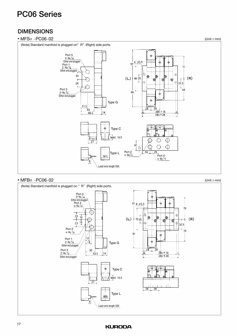
DIMENSIONS● MFS□ ー PC06ー 02 (Unit: mm)
● MFB□ ー PC06ー 02 (Unit: mm)
(Note) Standard manifold is plugged on“R”(Right) side ports.
(Note) Standard manifold is plugged on “R”(Right) side ports.
Type G
Type C
Type L
Type G
Type C
Type L
Port 5
Port 1
Port 3
Port 2Port 4
Either end plugged
Port 5
Port 4
Port 2
Port 1
Port 3
Either end plugged
Either end plugged
Either end plugged
Either end plugged
Either end plugged
Lead wire length 500
Lead wire length 500
17
PC06 Series
AC
Holding
Inlush
Po
wer
cons
ump
tion
Power consumption DC
Wiring
Mass
Fluid
Port size
Effective area
Cv value
Operating ambient temperature
Operating pressure range
Maximum frequency
Rated voltage
Grade of insulation
Permissible voltage fluctuation
Rated frequency
Model No. Unit
Response timeat 0.5MPa
V
%
Hz
VA
VA
VA
VA
W
kg
SPECIFICATIONS
s
mm2
℃
MPa
Cycle/min
(Note)・When temperature of valve site gose down below 5 ℃, complete dry air shall be supplied to prevent from freezing.・Effective area shown above is value between ports 1 and 2, 4.・Response time shown above is in accordance with JIS B 8375.
50Hz
60Hz
50Hz
60Hz
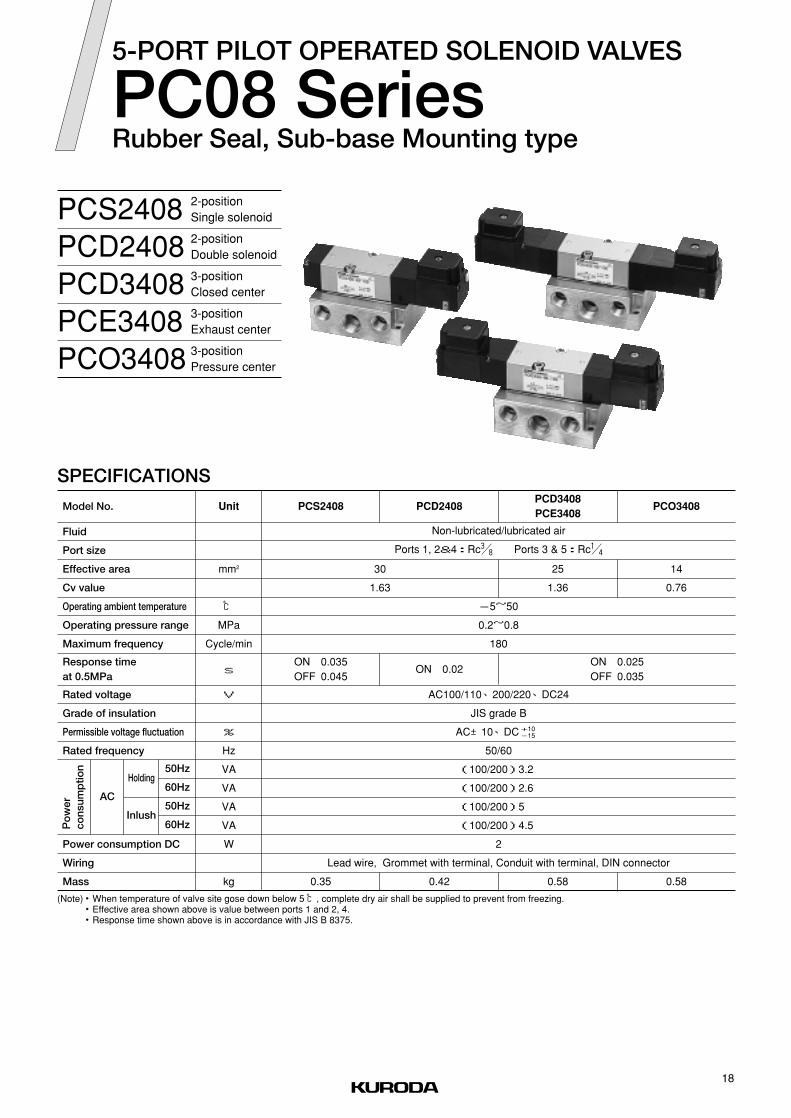
PCS2408PCD2408PCD3408PCE3408PCO3408
2-positionSingle solenoid
2-positionDouble solenoid
3-positionClosed center
3-positionExhaust center
3-positionPressure center
AC100/110、200/220、DC24
JIS grade B
AC±10、DC
50/60
(100/200)3.2
(100/200)2.6
(100/200)5.0
(100/200)4.5
2
Lead wire, Grommet with terminal, Conduit with terminal, DIN connector
+10-15
0.35 0.42 0.58 0.58
PCS2408
ON 0.035OFF 0.045
ON 0.02ON 0.025OFF 0.035
-5~50
0.2~0.8
180
30
1.63
Non-lubricated/lubricated air
Ports 1, 2&4:Rc# / 8 Ports 3 & 5:Rc! / 4
PCD2408PCD3408PCE3408
PCO3408
25
1.36
14
0.76
18
5-PORT PILOT OPERATED SOLENOID VALVES
PC08 SeriesRubber Seal, Sub-base Mounting type

ORDERING INSTRUCTION
PCS2408 03-
PCS2408
PCD2408
PCD3408
PCE3408
PCO3408
-
Model No.1
21 3 4
100
AC100/110VAC200/220VDC24V
100200D24
Voltage4
L L
5
Rc# / 8Without sub-base
03NB
Port size3
CONSTRUCTION●PCS2408
6
Standard (Internal pilot)No markExternal pilot (Pilot port on sub-base)X
Special specifications2
Lead wireGrommet with terminalConduit with terminalGrommet with surge suppressorConduit with surge suppressorDIN connector
Wiring5
LGC※GK※CK
D
Standard (None locking)With locking button
No mark※L
Manual override6
※:Made to order
SPARE PARTS
Port size
Sub-base
Model No.
Rc# / 8
Rc# / 8(For external pilot)
PC08ーSBー03
PC08ーSBーX03
19
PC08 Series
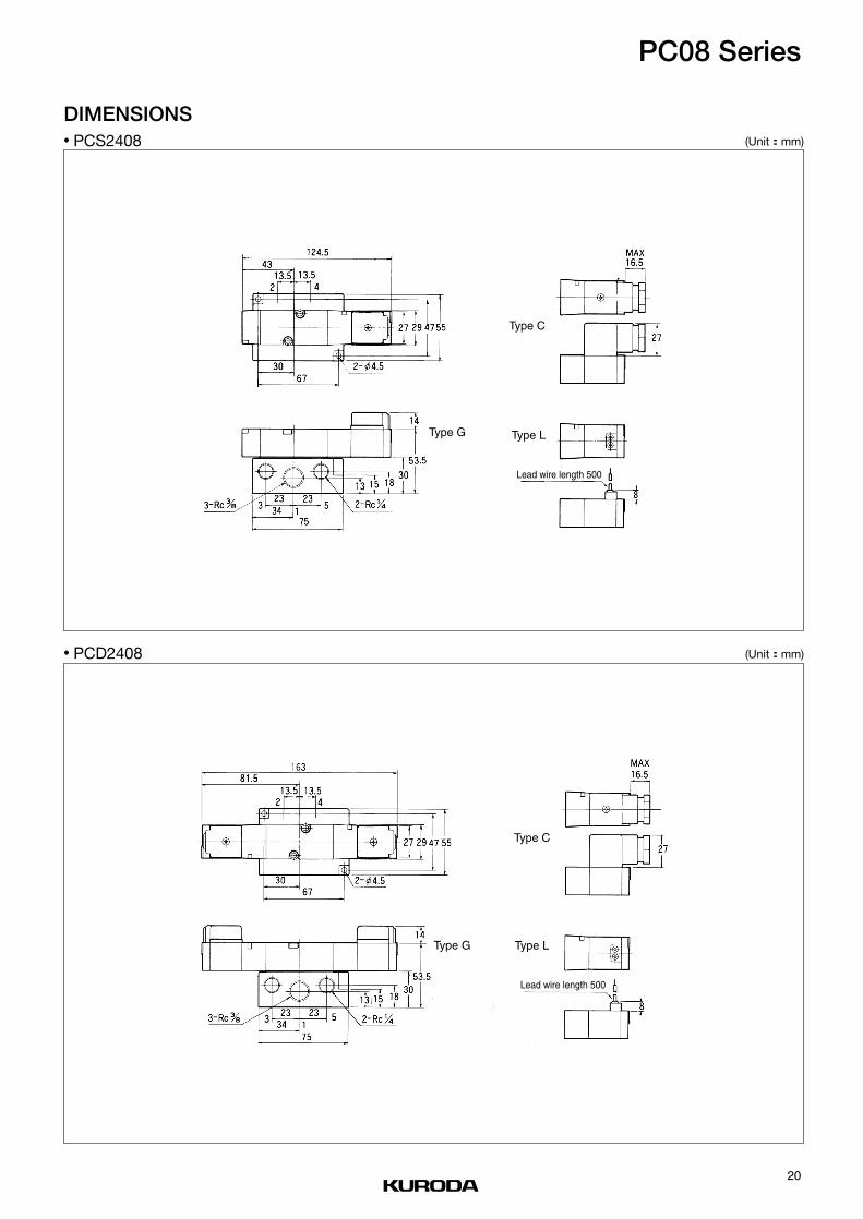
DIMENSIONS● PCS2408 (Unit: mm)
● PCD2408 (Unit: mm)
Type G
Type C
Type L
Lead wire length 500
Type G
Type C
Type L
Lead wire length 500
20
PC08 Series

DIMENSIONS● PCD3408、 PCE3408、 PCO3408 (Unit: mm)
Type G
Type C
Type L
Lead wire length 500
21
PC08 Series

Type of manifold
MF□ーPC08
Common SUP, common EXH
Ports 2 & 4 on both sides
Rc! / 2(Both sides)
Rc! / 2(Both sides)
Rc# / 8(Both sides)
2~10
PCS2408-NB-※
PCD2408-NB-※
PCD3408-NB-※
PCE3408-NB-※
PCO3408-NB-※
PC08–BP
Rc! / 2(Both sides)
Rc! / 2(Both sides)
Rc# / 8(Side)
Common SUP, common EXH
Ports 2 & 4 on side
MFS□ーPC08
Port size
Port 1
Port 3, 5
Port 2, 4
Number of stations
Mountable solenoid valve
Blank plate
MANIFOLD SPECIFICATIONS
MF□ーPC08Separate type
Common SUP, Common EXHPorts 2 & 4 on both sides
MFS□ーPC08Bar type
Available for multipurpose
Common SUP, Common EXHPorts 2 & 4 on side
As pilot air supply is branched in manifold,it can be used for special purposes suchas double supply, low pressure, vacuum,etc. (Refer to Page 10)
HOW TO ORDER
Parts of Separate type Manifold
Specifi the type and quantity of Manifold and Solenoid Valve to be mounted, and the quantityof Blank Plate (PC08-BP) in accordance with the following example of description.
(Example) MFS8-PC08-03PCS2408-NB-100G
PCD2408-NB-100G
PCD3408-NB-100G
PC08-BP
4 pcs.
2 pcs.
1 pc.
1 pc.
Patrs Name Parts No.
End block set MF-PC08-MB
Manifold block MF-PC08-BD
(Note) Mounting screws & O-ring are supplied
CAUTION When mounting a solenoid valve to be used at different pressure on the same manifold, mount asolenoid valve intended to be used by supplying the highest pressure (0.8MPa maximum) from port 1on one of the right end or left end.
Manifold of MF□-PC08 used a coupling method for single-station type manifold.
For special circuits, use “Specification for Manifold”.●
●
●
22
INDIVIDUAL WIRING TYPE MANIFOLD
MF○ーPC08Separate type/Bar type

ORDERING INSTRUCTION
Voltage3
100
200D24
AC100/110V
AC200/220V
DC24V
Model No.1
PCS2408
PCD2408
PCD3408
PCE3408
PCO3408
Port size2
NB Without sub-base
Manifold
Mountable solenoid valve (For details refer to Pages 18 to 21.)
Type of manifold1
MFSBar typeCommon SUP, Common EXHPorts 2 & 4 on side
MFSeparate typeCommon SUP, common EXHPorts 2 & 4 on both sides
Mountable solenoid valve3
PC08 PC08 series
Number of stations2
2
… …10
2 station
10station
Size of ports 2 and 44
03 Rc# / 8
Special specifications5
No mark Standard
A Bottom ported
(Note) A:MF only
Standard (None locking)With locking button
Lead wireGrommet with terminalConduit with terminalGrommet with surge suppressorConduit with surge suppressorDIN connector
Wiring4
No mark※L
Manual override5
LGC※GK※CK
D
※:Made to order
MFS 2 PC08- -
21 3 4
03 -
5
PCS2408 NB- -
1 2 3
100 L
54
23
PC08 Series

MF□- PC08●
MFS□- PC08●
DIMENSIONS
Bottom ported (Special specification)
Type LType C
Type G
( L) ( R)
(Note) Standard manifold is plugged on“R” (Right) side ports.
( R)
(Note) Standard manifold is plugged on“R”(Right) side ports.
( L)
Type G
Type C
Type L
(Unit: mm)
(Unit: mm)
Port 4
Port 5
Port 3
Port 2
Port 3
Port 3
Either end plugged
Either end pluggedPort 1
Either end plugged
Port 4
Port 2
Either end plugged
Port 1
Port 5
Port 4
Either end plugged
Either end plugged
Port 5
Port 1
Port 2
Lead wire length 500
Lead wire length 500
24
PC08 Series

PCS2415PCD2415PCD3415PCE3415PCO3415
2-positionSingle solenoid
2-positionDouble solenoid
3-positionClosed center
3-positionExhaust center
3-positionPressure center
Non-lubricated/lubricated air
Ports 1, 2 & 4:Rc!/2 Ports 3 & 5:Rc#/8
0.2~0.8 0.25~0.8
-5~50
120
ON 0.035
OFF 0.060ON 0.02
Lead wire, Grommet with terminal, Conduit with terminal, DIN connector
2
50/60
(100/200)3.2
(100/200)2.6
(100/200)5.0
(100/200)4.5
AC100/110、200/220、DC24
JIS grade B
AC±10、DC+10-15
0.73 0.81 0.94 0.94
ON 0.025
OFF 0.110
70
3.80
60
3.25
PCS2415 PCD2415PCD3415PCE3415
PCO3415
AC
Holding
Inlush
Po
wer
cons
ump
tion
Power consumption DC
Wiring
Mass
Fluid
Port size
Effective area
Cv value
Operating ambient temperature
Operating pressure range
Maximum frequency
Rated voltage
Grade of insulation
Permissible voltage fluctuation
Rated frequency
Model No. Unit
Response timeat 0.5MPa
V
%
Hz
VA
VA
VA
VA
W
kg
SPECIFICATIONS
s
mm2
℃
MPa
Cycle/min
(Note)・When temperature of valve site gose down below 5 ℃, complete dry air shall be supplied to prevent from freezing.・Effective area shown above is value between ports 1 and 2, 4.・Response time shown above is in accordance with JIS B 8375.
50Hz
60Hz
50Hz
60Hz
25
5-PORT PILOT OPERATED SOLENOID VALVES
PC15 SeriesRubber Seal, Sub-base Mounting type

ORDERING INSTRUCTION
Special specifications2
No mark Standard (Internal pilot)
XExternal pilot (Pilot port on sub-base)
Port size3
04 Rc !/2
NB Without sub-base
Model No.1
PCS2415
PCD2415
PCD3415
PCE3415
PCO3415
Voltage4
100
200D24
AC100/110V
AC200/220V
DC24V
CONSTRUCTION
●PCS2415
Standard (None locking)With locking button
Lead wireGrommet with terminalConduit with terminalGrommet with surge suppressorConduit with surge suppressorDIN connector
Wiring5
No mark※L
Manual override6
LGC※GK※CK
D
※:Made to order
SPARE PARTS
Port size
Sub-base
Model No.
RcRc!/2
Rc!/2(For external pilot)
PC15ーSBー04
PC15ーSBーX04
PCS2415 04- -
21 3 4
100 L
5 6
26
PC15 Series

DIMENSIONS● PCS2415 (Unit: mm)
● PCD2415 (Unit: mm)
Type G
Type C
Type L
Type G
Type C
Type L
Lead wire length 500
Lead wire length 500
27
PC15 Series

DIMENSIONS● PCD3415、 PCE3415、 PCO3415 (Unit: mm)
Type G
Type C
Type L
Lead wire length 500
28
PC15 Series

MF□ーPC15Common SUP, common EXH
Ports 2 & 4 on both sides
Blank plate
Mountable solenoid valve
Number of stations
Port 1
Port 3, 5
Port 2, 4
Port size
Type of manifold
MF□ーPC15Common SUP, Common EXHPorts 2 & 4 on both sides
MANIFOLD SPECIFICATIONS
Rc# / 4(Both sides)
Rc# / 4(Both sides)
Rc! / 2(Both sides)
2~10
PC15ーBP
PCS2415ーNBー※PCD2415ーNBー※PCD3415ーNBー※PCE3415ーNBー※PCO3415ーNBー※
HOW TO ORDERSpecify the type and quantity of Manifold and Solenoid valve to be mounted, and the quantity of Blank Plate (PC08-BP) in accordance with the following example of description.
(Example) MF8ーPC15ー04PCS2415ーNBー100G 4pcs.
PCD2415ーNBー100G 2pcs.
PCD3415ーNBー100G 1pc.
PC15ーBP 1pc.
Available for multipurposeAs pilot air supply is branched in manifold, it can beused for special purpose such as double supply, lowpressure, vacuum, etc. (Refer to Page 10.)
Patrs Name
Parts of Separate type ManifoldParts No.
MFーPC15ーMB
MF1ーPC15ーBD
End block set
Manifold block
(Note) Mounting screws & O-ring are supplied
CAUTION When mounting a solenoid valve to be used at different pressure on the same manifold, mount a solenoidvalve intended to be used by supplying the highest pressure (0.8MPa maximum) from port 1 on one of theright end or left end.For special circuits, use“Specification for Manifold”.●
●
29
INDIVIDUAL WIRING TYPE MANIFOLD
MF○ーPC15Bar type

ORDERING INSTRUCTION
Manifold
MF 2 PC15-
PCS2415
PCD2415
PCD3415
PCE3415
PCO3415
-
Model No.
Mountable solenoid valve (For details refer to Pages 25 to 28.)
PCS2415- NB-
1
Type of manifold
MF
1
21 3 4
1
04
2 2 station… …10 10station
Number of stations2
PC15 seriesPC15
Mountable solenoid valve3
AC100/110VAC200/220VDC24V
Without sub-base
100200D24
NB
Port size2
Voltage3
2
Rc! / 204
Size of ports 2 and 44
3 4
100 L
5
StandardBottom ported
No markA
Special specifications5
-
5
Common SUP, common EXHPorts 2 & 4 on both sides
Standard (None locking)With locking button
Lead wireGrommet with terminalConduit with terminalGrommet with surge suppressorConduit with surge suppressorDIN connector
Wiring4
No mark※L
Manual override5
LGC※GK※CK
D
※:Made to order
30
PC15 Series

DIMENSIONS● MF□ ー PC15 (Unit: mm)
(Note) Standard manifold is plugged on“R”(Right) side ports.
Type G
Type C
Bottom ported (Special specification)
Type L
Port 1
Port 3Port 3
Port 2
Port 1Port 5
Port 5
Port 4
Port 2
Port 4(Either end plugged)
(Either end plugged)
(Either end plugged)
Mounting hole
Lead wire length 500
31
PC15 Series

AC
Holding
Inlush
Po
wer
cons
ump
tion
Power consumption DC
Wiring
Mass
Fluid
Port size
Effective area
Cv value
Operating ambient temperature
Operating pressure range
Maximum frequency
Rated voltage
Grade of insulation
Permissible voltage fluctuation
Rated frequency
Model No. Unit
Response timeat 0.5MPa
V
%
Hz
VA
VA
VA
VA
W
kg
SPECIFICATIONS
s
mm2
℃
MPa
Cycle/min
(Note)・When temperature of valve site gose down below 5 ℃, complete dry air shall be supplied to prevent from freezing.・Effective area shown above is value between ports 1 and 2, 4.・Response time shown above is in accordance with JIS B 8375.
50Hz
60Hz
50Hz
60Hz
RCS2406RCD2406RCD3406RCE3406RCO3406
2-positionSingle solenoid
2-positionDouble solenoid
3-positionClosed center
3-positionExhaust center
3-positionPressure center
AC100/110、200/220、DC24
JIS grade B
AC±10、DC
50/60
(100/200)3.2
(100/200)2.6
(100/200)5.0
(100/200)4.5
2
Lead wire, Grommet with terminal, Conduit with terminal, DIN connector
+10-15
0.14 0.21 0.3 0.3
RCS2406
ON 0.021OFF 0.021
ON 0.015ON 0.025OFF 0.035
-5~50
0.2~0.8
12
0.65
Non-lubricated/lubricated air
Ports 1, 2 & 4:Rc! / 4 Ports 3 & 5:Rc! / 8
RCD2406RCD3406RCE3406
RCO3406
11
0.60
240 180
32
5-PORT PILOT OPERATED SOLENOID VALVES
RC06 SeriesRubber Seal, In-line Mounting type

ORDERING INSTRUCTION
RCS2406
RCD2406
RCD3406
RCE3406
RCO3406
Model No.1
AC100/110VAC200/220VDC24V
100200D24
Voltage3
Rc! / 402
Port size2
CONSTRUCTION●RCS2406
RCS2406 02- -
21 3 4
100 L
5 6
StandardWith mounting bracket
No markB
Special specifications6
Standard (None locking)With locking button
Lead wireGrommet with terminalConduit with terminalGrommet with surge suppressorConduit with surge suppressorDIN connector
Wiring4
No mark※L
Manual override5
LGC※GK※CK
D
※:Made to order
33
RC06 Series

(Unit: mm)
DIMENSIONS● RCS2406
● RCD2406 (Unit: mm)
Type G
Type C
Type L2-M4×0.7 depth 5
Lead wire length 500
Type G
Type C
Type L2-M4×0.7 depth 5 Lead wire length 500
Bracket
Bracket
34
RC06 Series

DIMENSIONS● RCD3406、 RCE3406、 RCO3406 (Unit: mm)
Type G
Type C
Type L2-M4×0.7 depth 5Lead wire length 500
Bracket
35
RC06 Series
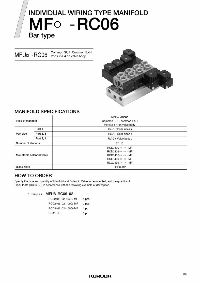
Blank plate
Mountable solenoid valve
Number of stations
Port 1
Port 3, 5
Port 2, 4
Port size
Type of manifold
MANIFOLD SPECIFICATIONS
MFU□ーRC06Common SUP, Common EXHPorts 2 & 4 on valve body
HOW TO ORDERSpecify the type and quantity of Manifold and Solenoid Valve to be mounted, and the quantity ofBlank Plate (RC06-BP) in accordance with the following example of description.
(Example) MFU8ーRC06ー02RCS2406ー02ー100GーMF 4 pcs.
RCD2406ー02ー100GーMF 2 pcs.
RCD3406ー02ー100GーMF 1 pc.
RC06ーBP 1 pc.
MFU□ーRC06Common SUP, common EXH
Ports 2 & 4 on valve body
Rc! / 4(Both sides)
Rc! / 4(Both sides)
Rc! / 4(Valve body)
2~10
RC06ーBP
RCS2406ー※ー※ーMFRCD2406ー※ー※ーMFRCD3406ー※ー※ーMFRCE3406ー※ー※ーMFRCO3406ー※ー※ーMF
36
INDIVIDUAL WIRING TYPE MANIFOLD
MF○ーRC06Bar type

MFU
Common SUP, common EXHPorts 2 & 4 on valve body
ORDERING INSTRUCTION
Manifold
2 RC06-
RCS2406
RCD2406
RCD3406
RCE3406
RCO3406
-
Model No.
Mountable solenoid valve (For details refer to Pages 32 to 35.)
RCS2406- 02 -
1
Type of manifold
MFU
1
21 3 4
1
02
2 2 station… …10 10station
Number of stations2
RC06 seriesRC06
Mountable solenoid valve3
AC100/110VAC200/220VDC24V
Rc! / 4
100200D24
02
Port size2
Voltage3
2
Rc! / 402
Size of ports 2 and 44
3 4
100 L
5
-MF
For manifold
Standard (None locking)With locking button
Lead wireGrommet with terminalConduit with terminalGrommet with surge suppressorConduit with surge suppressorDIN connector
Wiring4
No mark※L
Manual override5
LGC※GK※CK
D
※:Made to order
37
RC06 Series

(Unit: mm)
DIMENSIONS● MFU□ ー RC06ー 02
(Note) Standard manifold is plugged on“R”(Right) side ports.
Type G
Type C
Type L
Port 5
Port 1
Either end plugged
Either end plugged Port 4
Port 2
Port 3
Either end plugged
Lead wire length 500
38
RC06 Series

AC
Holding
Inlush
Po
wer
cons
ump
tion
Power consumption DC
Wiring
Mass
Fluid
Port size
Effective area
Cv value
Operating ambient temperature
Operating pressure range
Maximum frequency
Rated voltage
Grade of insulation
Permissible voltage fluctuation
Rated frequency
Model No. Unit
Response timeat 0.5MPa
V
%
Hz
VA
VA
VA
VA
W
kg
SPECIFICATIONS
s
mm2
℃
MPa
Cycle/min
(Note)・When temperature of valve site gose down below 5 ℃, complete dry air shall be supplied to prevent from freezing.・Effective area shown above is value between ports 1 and 2, 4.・Response time shown above is in accordance with JIS B 8375.
50Hz
60Hz
50Hz
60Hz
PCS2408RCD2408RCD3408RCE3408RCO3408
AC100/110、200/220、DC24
JIS grade B
AC±10、DC
50/60
(100/200)3.2
(100/200)2.6
(100/200)5.0
(100/200)4.5
2
Lead wire, Grommet with terminal, Conduit with terminal, DIN connector
+10-15
ー5~50
0.2~0.8
Non-lubricated/lubricated air
Ports 1, 2 & 4:Rc# / 8 Ports 3 & 5:Rc! / 4
180
ON 0.035
OFF 0.045ON 0.02
ON 0.025
OFF 0.035
0.16 0.23 0.29 0.29
30
1.63
25
1.36
14
0.76
RCS2408 RCD2408RCD3408
RCE3408RCO3408
2-positionSingle solenoid
2-positionDouble solenoid
3-positionClosed center
3-positionExhaust center
3-positionPressure center
39
5-PORT PILOT OPERATED SOLENOID VALVES
RC08 SeriesRubber Seal, In-line Mounting type

ORDERING INSTRUCTION
CONSTRUCTION
Model No.1
RCS2408 100 L03- -1 2 3 4 5
Voltage3
100 AC100/110V
200 AC200/220V
D24 DC24V
Port size2
03 Rc# / 8
RCS2408
RCD2408
RCD3408
RCE3408
RCO3408
●RCS2408
Standard (None locking)With locking button
Lead wireGrommet with terminalConduit with terminalGrommet with surge suppressorConduit with surge suppressorDIN connector
Wiring4
No mark※L
Manual override5
LGC※GK※CK
D
※:Made to order
40
RC08 Series

● RCD2408
● RCS2408DIMENSIONS
(Unit: mm)
(Unit: mm)
Type L
Type G
Type C
Type L
Type G
Type C
Lead wire length 500
Lead wire length 500
41
RC08 Series

(Unit: mm)● RCD3408、 RCE3408、 RCO3408DIMENSIONS
Type L
Type G
Type C
Lead wire length 500
42
RC08 Series

Type of manifold
Port size
Port 1
Port 3, 5
Port 2, 4
Number of stations
Mountable solenoid valve
Blank plate
MANIFOLD SPECIFICATIONS
Rc! / 2(Both sides)
Rc! / 2(Both sides)
Rc# / 8(Valve body)
2~10
RC08-BP
RCS2408-※-※-MF
RCD2408-※-※-MF
RCD3408-※-※-MF
RCE3408-※-※-MF
RCO3408-※-※-MF
MFU□ーRC08
Common SUP, common EXH
Ports 2 & 4 on valve body
MFU□ーRC08Common SUP, Common EXHPorts 2 & 4 on valve body
Specify the type and quantity of Manifold and Solenoid Valve to be mounted, and the quantity of BlankPlate (RC08-BP) in accordance with the following example of description.
HOW TO ORDER
(Example) MFU8-RC08-03RCS2408-03-100G-MF 4 pcs.
RCD2408-03-100G-MF 2 pcs.
RCD3408-03-100G-MF 1 pc.
RC08-BP 1 pc.
43
INDIVIDUAL WIRING TYPE MANIFOLD
MF◯-RC08Bar type

ORDERING INSTRUCTION
2MFU 03RC08- -1 2 3 4
Size of ports 2 and 44
Type of manifold 1
Manifold
Mountable solenoid valve (For details refer to Pages 39 to 42.)
Number of stations2
2 2 station
… …
20 10station
RC08 RC08 seriesCommon SUP, common EXH
Ports 2 & 4 on valve bodyMFU
Rc# / 803
Mountable solenoid valve3
Voltage3
100 AC100/110V
200 AC200/220V
D24 DC24V
Port size2
03 Rc# / 8
RCS2408 100 L03- -1 2 3 4 5
Model No.1
RCS2408
RCD2408
RCD3408
RCE3408
RCO3408
MF-For manifold
Standard (None locking)With locking button
Lead wireGrommet with terminalConduit with terminalGrommet with surge suppressorConduit with surge suppressorDIN connector
Wiring4
No mark※L
Manual override5
LGC※GK※CK
D
※:Made to order
44
RC08 Series

(Unit: mm)● MFU□ -RC08DIMENSIONS
Type L
Type G
Type C
(Note) Standard manifold is plugged on“R”(Right) side ports.
Lead wire length 500
Port 5
Port 1Either end plugged
Either end plugged
Port 3
Port 2
Either end plugged
45
RC08 Series

CAT. NO.KA192-○b

PILOT OPERATED SOLENOID VALVES
PM SeriesMetal Seal, In-line Mounting/Sub-base Mounting

1
LAPPED SPOOL & SLEEVE, PILOT OPERATED SOLENOID VALVES
PM Series
The solenoid operated air valves of this series are types with an internal-pilot-type metal sealand a spool valve. This provides a choice of 3-way (3 ports), 4-way (5 ports), 2-position with single or doublesolenoid, and 3-position with closed center or exhaust center models, in conformity withcustomer's requirements.

2
FEATURES
Small, Light and High Flow RateThe compact size is achieved by the well-designed flow path construction and aluminum-alloy bases and small
pilot solenoid valves, and a larger Cv Factor as well as a light weight are being accomplished for its sizes.
Long Service LifeThe valve incorporates a metal seal system composed of a sleeve and a spool on which KURODA's super precision
machining technique in making various kinds of gauges are embodied. The sleeve and spool assembly is made of
special stainless steel that provides anti-corrosion and is being hardened at Rockwell C60 for anti-weariness.
Besides the assemblies being made to fit with a several micron clearance one another results slightest air leak
and allow the spool to float in the sleeve. Accordingly this not only can be used under without lubrication but
also assures a long service life for its small friction that affects a minimum wear and high sealing effects.
No Coil Burn OutThese valves are operated by pneumatic power to shift the spool to obtain greater shifting force. And because
of its small resin-molded solenoid coil a low power consumption is expected.
This coil will not burn out in cases of sleeve or spool malfunction which would be typical causes for failure by
presence of deteriorated compressor oil, pipe scale, sand or unnecessary viscous oil in the lubricator if a direct
operated valve was used.
Quick Response and Positive ShiftingMinimized internal volume of the pilot portion provides short response time though a pilot type. Pneumatic power
gives a greater shifting power for positive switching of the spool.
Plug-in ConnectorA plug-in connector (DIN43650) is used in the electric joint portion for the ease of connection.
The conduit opening of the connector can be directed in any direction.
Locking Manual overrideTo enable manual operation, a locking button of KURODA's unique design comes as option.
(None lock manual override is standard)
Flow PatternAs the standard solenoid valves are internal pilot type, air pressure must be fed from its port 1. But by plugging
other ports these can be used as 2-way, 3-way, or 4-way valves.
MountingThese solenoid valves are sub-base mounting types in discrete use but manifold mounting isavailable for the
demand of combination use (except for 3-way model).
The same interface is being placed between the valve body and sub-base as used with KURODA's direct operated
solenoid valves so that these valve bodies are interchangeable with the direct types.

3
VARIATION
FEATURES ―――――――――――――――――――――――――――――――――――――――――――P.1
VARIATION ―――――――――――――――――――――――――――――――――――――――――――P.3
INTORODUCTION OF KURODA CAD DATA LIBRARY―――――――――――――――――――――――P.4
FOR SAFETY USE――――――――――――――――――――――――――――――――――――――――P.5
SOLENOID VALVE/COMMON INSTRUCTIONS ――――――――――――――――――――――――――P.6
5-PORT PAILOT OPERATED SOLENOID VALVE PM6 series ――――――――――――――――――P.11
3/5-PORT PAILOT OPERATED SOLENOID VALVE PM06 series ―――――――――――――――――P.14
3/5-PORT PAILOT OPERATED SOLENOID VALVE PM08 series ―――――――――――――――――P.17
3/5-PORT PAILOT OPERATED SOLENOID VALVE PM10 series ―――――――――――――――――P.20
3/5-PORT PAILOT OPERATED SOLENOID VALVE PM15 series ―――――――――――――――――P.23
3/5-PORT PAILOT OPERATED SOLENOID VALVE PM25 series ―――――――――――――――――P.26
INDIVIDUAL WIRING TYPE MANIFOLD MF○-C ―――――――――――――――――――――――――P.29
CONTENTS
Model No. Port Solenoid Positions Port sizeEffective area
(mm2)Cv value Refer to Page:
Rc1/8 116.5 0.35
11
12.5
12
22
30
25
38
50
80
75
190
0.60
0.68
0.65
1.19
1.63
1.35
2.06
2.71
4.34
4.07
10.3
Rc1/8, 1/4
Rc1/4, 3/8
Rc3/8, 1/2
Rc1/2, 3/4
Rc3/4, 1, 11/4
14
17
20
23
26
2
2
3-Closed center
3-Exhaust center
3-Closed center
3-Exhaust center
2
3-Closed center
3-Exhaust center
2
3-Closed center
3-Exhaust center
2
3-Closed center
3-Exhaust center
2
3-Closed center
3-Exhaust center
Single
Single
Double
Double
Single
Double
Single
Double
Single
Double
Single
Double
5
5
3
5
3
5
3
5
3
5
3
PMS246
PMD246
PMD346
PME346
PMS2306
PMS2406
PMD2406
PMD3406
PME3406
PMS2308
PMS2408
PMD2408
PMD3408
PME3408
PMS2310
PMS2410
PMD2410
PMD3410
PME3410
PMS2315
PMS2415
PMD2415
PMD3415
PME3415
PMS2325
PMS2425
PMD2425
PMD3425
PME3425
Rc3/4, 1170 (Rc3/4 )200 (Rc1)210 (Rc11/4 )
9.22 (Rc 3/4 )10.84 (Rc1)11.39 (Rc11/4 )
8.94 (Rc 3/4 )10.29 (Rc1)10.57 (Rc11/4 )
165 (Rc3/4 )190 (Rc1)195 (Rc11/4 )
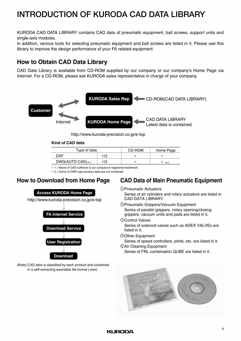
4
http://www.kuroda-precision.co.jp/e-top
Access KURODA Home Page
FA Internet Service
Download Service
User Registration
Download
CD-ROM(CAD DATA LIBRARY)
CAD DATA LIBRARYLatest data is contained.
Customer
KURODA Sales Rep
KURODA Home Page Internet
http://www.kuroda-precision.co.jp/e-top
KURODA CAD DATA LIBRARY contains CAD data of pneumatic equipment, ball screws, support units andsingle-axis modules.In addition, various tools for selecting pneumatic equipment and ball screws are listed in it. Please use thislibrary to improve the design performance of your FA related equipment.
CAD Data Library is available from CD-ROM supplied by our company or our company's Home Page viaInternet. For a CD-ROM, please ask KURODA sales representative in charge of your company.
How to Obtain CAD Data Library
How to Download from Home Page CAD Data of Main Pneumatic Equipment①Pneumatic Actuators
Series of air cylinders and rotary actuators are listed inCAD DATA LIBRARY.
②Pneumatic Grippers/Vacuum EquipmentSeries of parallel grippers, rotary opening/closinggrippers, vacuum units and pads are listed in it.
③Control ValvesSeries of solenoid valves such as ADEX VALVEs arelisted in it.
④Other EquipmentSeries of speed controllers, joints, etc. are listed in it.⑤Air Cleaning Equipment
Series of FRL combination QUBE are listed in it.
Kind of CAD data
Type of data CD-ROM
○
○
Home Page
○*2○*2
DXF
DWG(AUTO CAD)*1
r12
r12
※1:Name of CAD software is our company's registered trademark.※2:Some of DWG type product data are not contained
(Note) CAD data is classified by each product and containedin a self-extracting exectable file format (.exe).
INTRODUCTION OF KURODA CAD DATA LIBRARY

5
FOR SAFETY USEBe sure to read the following instructions before use.For common and individual instructions, refer to the text of this catalogue.
Pneumatic fluid power-General rules relating to systems

6
SOLENOID VALVES/COMMON INSTRUCTIONS ①Be sure to read them before use.Also refer to Par. "For Safety Use" and instructions mentioned for each series of solenoid valves.
WARNINGStopping actuator at intermediate positionWhen stopping the actuator at an intermediate position using asolenoid valve listed in this catalogue, it is difficult to stop itaccurately because of the compressibility of air, unlike a hydrau-lic cylinder can dose.In addition, as the solenoid valve and air cylinder allow a certaindegree of air leak, they cannot stop at the fixed position for along period of time according to circumstances. When it isrequired to stop them at the fixed position for a long period oftime, contact KURODA.
Keeping pressure (including vacuum)As the solenoid valve is designed to allow a certain degree of airleak, it cannot be used to keep pressure (including vacuum) in apressure vessel etc.
Do not use for emergency shutoff valves.Solenoid valves listed in this catalogue are not designed for usein emergency shutoff valves and other safety applications.When using the solenoid valve for such applications, provide anindependent means to assure safety.
Exhausting residual airProvide a residual air exhausting function in due consideration ofmaintenance and inspection. Doing maintenance and inspectionwithout exhausting residual air may sometimes malfunction theactuator.When using a 3-position closed center type solenoid valve,compressed air is shut in between solenoid valve and actuatoreven if residual air from the air supply side to the solenoid valveis exhausted.Therefore, provide a means to exhaust the residual air pressureseparately.
Use in vacuumWhen using a solenoid valve for diverting vacuum and otherapplications, check specifications for the valve and select aproper one that can be used in vacuum.In order to prevent sucking foreign matters from the suction padand exhaust port, provide an inline filter between the suctionpad and solenoid valve and at the exhaust port.
Applying current continuously for long timeWhen using a solenoid valve while applying current to itcontinuously for a long period of time, contact KURODAbeforehand.
Avoid applying current simultaneously.When using a double-solenoid valve while applying current to itcontinuously for a long period of time, do not apply current toboth solenoids simultaneously ; otherwise the coil may be burntout or the main valve may malfunction.
Remodeling the solenoid valveDo not remodel the solenoid valve.
CAUTIONApplying current momentarilyWhen using a double-solenoid type valve, apply current for theprescribed period of time (0.1 sec.). If current is not applied forthe prescribed period of time, the solenoid valve may notperform the diverting action acording to circumstances.
Leak currentWhen a C-R element is used in the contact protective circuit(surge voltage protection), leak current will flow through the C-Relement.If this leak current becomes large, a malfunction will occur.Therefore, reduce leak current to less than 1 mA.
Use at low temperatureWhen using a solenoid valve at 5 ℃ or below, provide an airdryer or other proper means to prevent moisture from solidifyingor freezing.
Use with air blowWhen using a solenoid valve with air blow, select a direct-operated type or external pilot type solenoid valve.When an internal pilot type solenoid valve is used, it may notperform the diverting action due to a pressure drop at the timeof air blow.When an external pilot type solenoid valve is used, supplycompressed air within the specified pressure range to the pilotport.
Mounting position and directionA solenoid valve can be mounted in any position and directionas a general.However, a metal seal type double-solenoid valve and a 3-positionsolenoid valve should be mounted so that the spool may behorizontal.
Shock and vibrationReduce shocks and vibrations applied to the solenoid valve toless than the prescribed value. (refer to specifications.)Applying shocks and vibrations exceeding the prescribed valuemay result in a malfunction of the solenoid valve.
¡
¡
¡
¡
¡
¡
DESIGN
¡
¡
¡
¡
¡
¡
¡
¡
DESIGN
Contact
Solenoid
Leak current
C-R circuit
Power supply

7
SOLENOID VALVES/COMMON INSTRUCTIONS ②Be sure to read them before use.Also refer to Par. "For Safety Use" and instructions mentiond for each series of solenoid valves.
WARNINGRefer to specifications.Solenoid valves listed in this catalogue are designed forcompressed air. When using other fluid than compressed air,contact KURODA beforehand.Do not use a solenoid valve at pressure and temperatureoutside the range of specifications, otherwise resulting in abreakdown or malfunction.
WARNINGWhen mounting the solenoid valve, firmly fix it whileusing care to prevent the stationary part and jointfrom loosening.If the solenoid valve is mounted with insufficient strength, it maysometimes come off.
Do not start the system until it is ensured that equip-ment works properly.After mounting the solenoid valve, connect power supply andthen perform a functional test and a leak test. Check that it hasbeen correctly mounted and works properly, before starting thesystem.
Coating with paintWhen coating the resin portion with paint, it may be adverselyaffected by paint and solvent. For the propriety of painting,contact KURODA beforehand.Do not peel off the nameplate affixed on the solenoid valve anddo not erase or smear out the letter on it.
Provide space for maintenance and inspection.
CAUTIONFit an air muffler to the exhaust port (ports 3, 5) of thesolenoid valve.Dust or foreign matter that enters it may cause a malfunction ofthe solenoid valve.
Do not wipe off the model name inscribed on anameplate etc. with organic solvent.The inscribed indication may be erased.
CAUTIONBefore pipingThoroughly flush the inside of each pipe to remove chips,coolant, dust, etc. before piping.
How to wind a seal tapeWhen winding a seal tape around the threaded portion, leavespace of 1.5 to 2 thread turns.
How to apply liquid sealantWhen applying liquid sealant to the threaded portion, apply aproper amount to about 1/3 of the periphery of the threadedportion and then screw it.
Screw of pipe and jointWhen screwing the pipe and joint, use care to prevent chipsand sealant from entering the pipe and joint.Tighten them within a proper range of clamping torque.
Port size Clamping torque (N.m)
M3 0.3~ 0.5
M5 1.5~ 2.0
R, Rc1/8 7.0~ 9.0
R, Rc1/4 12.0~14.0
R, Rc3/8 2.0~24.0
R, Rc1/2 28.0~30.0
R, Rc3/4 28.0~30.0
R, Rc1 36.0~38.0
R, Rc11/4 40.0~42.0
R, Rc11/2 48.0~50.0
¡
¡
¡
¡
PIPING
¡
¡
¡
¡
¡
¡
MOUNTING
¡
SELECTION
When screwing, seal tape enters equipment, causing air leak.
(Good) (No good)
Leave space of 1.5 to 2 turns.
Joint Sealant Apply sealant to this portion.1/3
↓ ↓
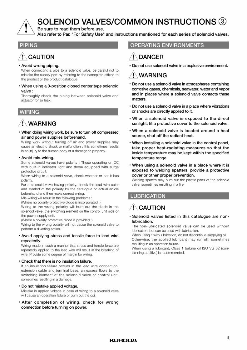
8
SOLENOID VALVES/COMMON INSTRUCTIONS ③Be sure to read them before use.Also refer to Par. "For Safety Use" and instructions mentioned for each series of solenoid valves.
CAUTIONAvoid wrong piping.When connecting a pipe to a solenoid valve, be careful not tomistake the supply port by referring to the nameplate affixed tothe product or the product catalogue.
When using a 3-position closed center type solenoidvalve :Thoroughly check the piping between solenoid valve andactuator for air leak.
WARNINGWhen doing wiring work, be sure to turn off compressedair and power supplies beforehand.Wiring work without turning off air and power supplies maycause an electric shock or malfunction ; this sometimes resultsin an injury to the human body or a damage to property.
Avoid mis-wiring.Some solenoid valves have polarity : Those operating on DCwith built-in indicator light and those equipped with surgeprotective circuit.When wiring to a solenoid valve, check whether or not it haspolarity.For a solenoid valve having polarity, check the lead wire colorand symbol of the polarity by the catalogue or actual articlebeforehand and then make correct wiring.Mis-wiring will result in the following problems :(Where no polarity protective diode is incorporated :)Wiring to the wrong polarity will burn out the diode in thesolenoid valve, the switching element on the control unit side orthe power supply unit.(Where a polarity protective diode is provided :)Wiring to the wrong polarity will not cause the solenoid valve toperform a diverting action.
Avoid applying stress and tensile force to lead wirerepeatedly.Wiring made in such a manner that stress and tensile force arerepeatedly applied to the lead wire will result in the breaking ofwire. Provide some degree of margin for wiring.
Check that there is no insulation failure.If an insulation failure occurs in the lead wire connection,extension cable and terminal base, an excess flows to theswitching element of the solenoid valve or control unit,sometimes resulting in a damage.
Do not mistake applied voltage.Mistake in applied voltage in case of wiring to a solenoid valvewill cause an operation failure or burn out the coil.
After completion of wiring, check for wrongconnection before turning on power.
DANGERDo not use solenoid valve in a explosive environment.
WARNINGDo not use a solenoid valve in atmospheres containingcorrosive gases, chemicals, seawater, water and vaporand in places where a solenoid valve contacts thesematters.
Do not use a solenoid valve in a place where vibrationsor shocks are directly applied to it.
When a solenoid valve is exposed to the directsunlight, fit a protective cover to the solenoid valve.
When a solenoid valve is located around a heatsource, shut off the radiant heat.
When installing a solenoid valve in the control panel,take proper heat-radiating measures so that theinside temperature may be kept within the specifiedtemperature range.
When using a solenoid valve in a place where it isexposed to welding spatters, provide a protectivecover or other proper prevention.Welding spaters may burn out the plastic parts of the solenoidvalve, sometimes resulting in a fire.
CAUTIONSolenoid valves listed in this catalogue are non-lubrication.The non-lubricated solenoid valve can be used withoutlubrication, but can be used with lubrication.When using it with lubrication, do not discontinue supplying oil.Otherwise, the applied lubricant may run off, sometimesresulting in an operation failure.When using a lubricant, Class 1 turbine oil ISO VG 32 (con-tainning additive) is recommended.
¡
LUBRICATION
¡
¡
¡
¡
¡
¡
¡
OPERATING ENVIRONMENTS
¡
¡
¡
¡
¡
¡
WIRING
¡
¡
PIPING

9
SOLENOID VALVES/COMMON INSTRUCTIONS ④Be sure to read them before use.Also refer to Par. "For Safety Use" and instructions mentioned for each series of solenoid valves.
WARNINGUse pure air.Compressed air containing corrosive gases, chemicals, salt,etc. causes a breakdown or operation failure. So do not usesuch air.
CAUTIONFit an air filter with filtration of 5 µm or fine.
Install an air dryer.Compressed air containing much drainage causes the operationfailure of pneumatic equipment. Install an air dryer, lower thetemperature and reduce drainage.
Take proper countermeasures against sludge.If sludge produced in compressor oil enters pneumatic equip-ment, it will cause the operation failure of pneumatic equipment.It is recommendable to use compressor oil (NISSEKI FAIRCALLA68, IDEMITSU DAPHUNY SUPER CS68) featuring minimizedsludge production or use a sludge filter or mist cleaner toprevent sludge from entering the pneumatic equipment.
WARNINGInspection before maintenanceFirst check that load drop prevention has been provided.Then shut off air and power supplies to the system and exhaustresidual air in the system beforehand.For a 3-position closed center type solenoid valve, compressedair is sealed between solenoid valve and cylinder.Exhaust this residual compressed air.
Inspection after maintenanceWhen restarting the system, check that preventive measuresagainst flying-out of the actuator have been taken. Thenconnect compressed air supply to the pneumatic system, andperform a proper functional test and a leak test to check that itworks safely without fail, before starting the system.
Operation at low frequencyTo prevent an operation failure, perform the switching action ofthe solenoid valve once per 30 days. (Be careful of air supply.)
Manual operationWhen the solenoid valve is manually operated, the systemconnected to it is also operated. Make sure safety beforeoperation.
Disassembly of solenoid valveWhen disassembling the solenoid valve, contact KURODAbeforehand.
CAUTIONDrainingTo keep the quality of air to a certain level, drain the air filter atperiodical intervals.
¡
¡
¡
¡
¡
¡
MAINTENANCE AND INSPECTION
¡
¡
¡
¡
QUALITY OF AIR
Filter Sludge filterMist cleaner
Regulator
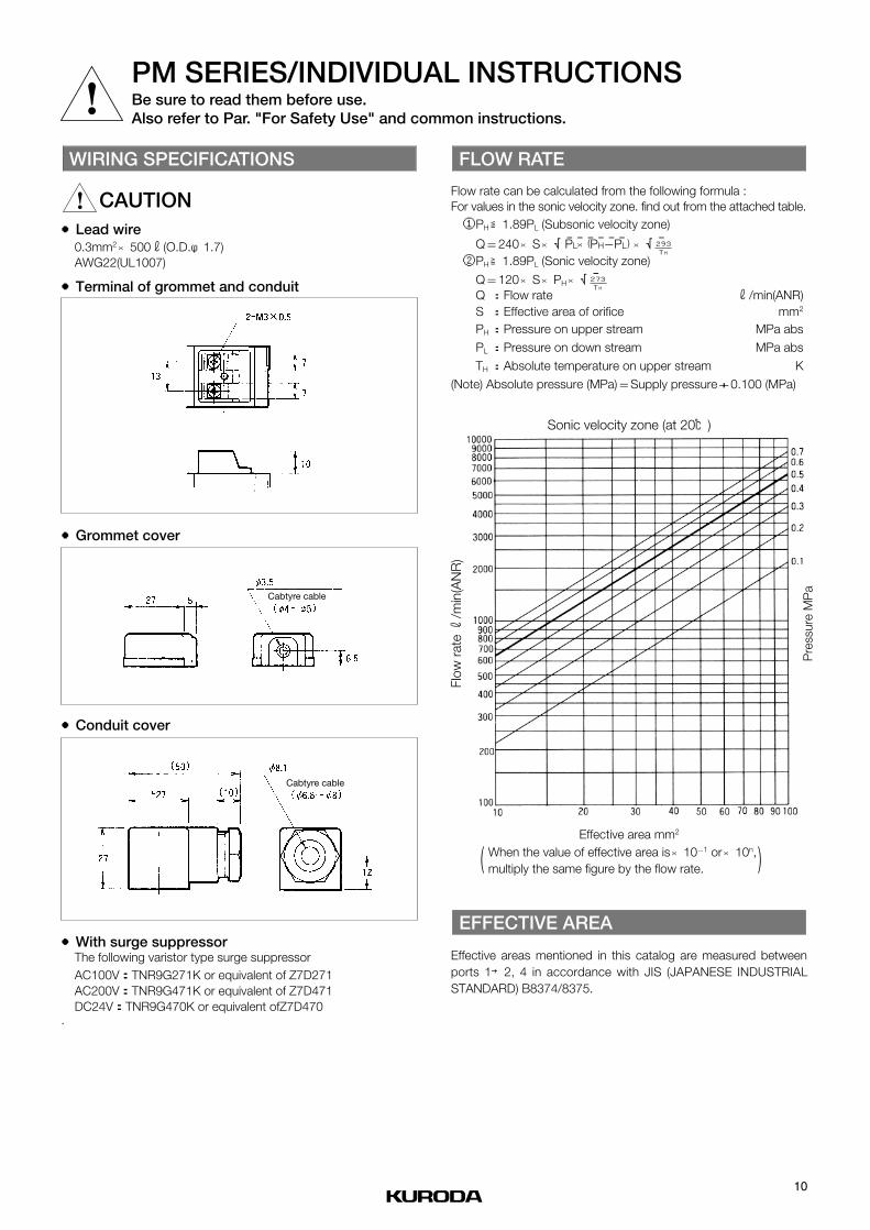
10
PM SERIES/INDIVIDUAL INSTRUCTIONSBe sure to read them before use.Also refer to Par. "For Safety Use" and common instructions.
CAUTION●Lead wire
0.3mm2 500r(O.D.φ1.7)AWG22(UL1007)
●Terminal of grommet and conduit
●Grommet cover
●Conduit cover
●With surge suppressorThe following varistor type surge suppressorAC100V:TNR9G271K or equivalent of Z7D271AC200V:TNR9G471K or equivalent of Z7D471DC24V:TNR9G470K or equivalent ofZ7D470
.
Flow rate can be calculated from the following formula : For values in the sonic velocity zone. find out from the attached table.①PH 1.89PL (Subsonic velocity zone)
Q 240 S √‾‾‾‾‾‾ √‾②PH 1.89PL (Sonic velocity zone)
Q 120 S PH √‾Q Flow rate r/min(ANR)S Effective area of orifice mm2
PH Pressure on upper stream MPa abs
PL Pressure on down stream MPa abs
TH Absolute temperature on upper stream K
(Note) Absolute pressure (MPa) Supply pressure 0.100 (MPa)
Effective areas mentioned in this catalog are measured between ports 1→2, 4 in accordance with JIS (JAPANESE INDUSTRIALSTANDARD) B8374/8375.
EFFECTIVE AREA
+=
:
:
:
:
:×××=
≧
×××=
≦
FLOW RATE
×
WIRING SPECIFICATIONS
Cabtyre cable
Cabtyre cable
293TH
273TH
Sonic velocity zone (at 20℃)
When the value of effective area is 10-1 or 10n,multiply the same figure by the flow rate.
××
Effective area mm2
Flow
rat
e r
/min
(AN
R)
Pre
ssur
e M
Pa
( )
PL×(PH-PL)

PMS246PMD246PMD346PME346
2-positionSingle solenoid
2-positionDouble solenoid
3-positionClosed center
3-positionExhaust center
Model No
Fluid
Port size
Effective area
Cv value
Operating ambient temperature
Operating pressure range
Maximum frequency
Unit
mm2
℃
MPa
Cycle/min
Non-lubricated/lubricated air
Rc! / 8
6.5
0.35
-5~60
360
0.15~1 0.2~1
AC100/110、200/220 DC24
JIS grade B
AC±10 DC
50/60
3.2(100/200)
2.6(100/200)
5.5(100/200)
4.5(100/200)
2
Lead wire, Grommet with terminal, Conduit with terminal, DIN connector
+10-15
s
(Average)
V
%
Hz
VA
VA
VA
VA
W
kg
PMS246 PMD246 PMD346 PME346
0.16 0.24 0.26 0.26
ON 0.022
OFF 0.012ON 0.010
ON 0.015
OFF 0.015
Response time
(at 0.5MPa)
AC
Holding50Hz
60Hz
50Hz
60HzInlush
Rated voltage
Grade of insulation
Permissible voltage fluctuation
Rated frequency
Power consumption DC
Wiring
Mass
SPECIFICATIONS
(Note)・When temperature of valve site gose down below 5 ℃, complete dry air shall be supplied to prevent from freezing.・Effective area shown above is value between ports 1 and 2, 4.・Response time shown above is in accordance with JIS B 8375.
Po
wer
cons
ump
tion
11
5-PORT PILOT OPERATED SOLENOID VALVES
PM6 SeriesMetal Seal, Sub-base Mounting type
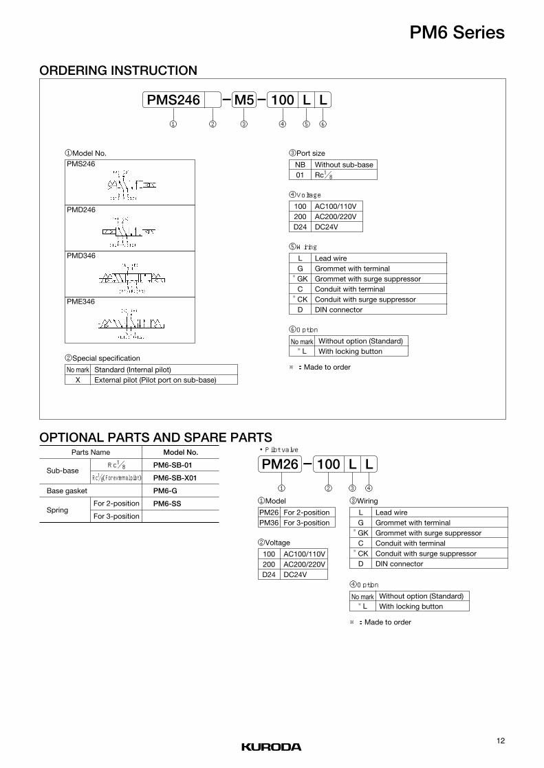
12
PM6 Series
ORDERING INSTRUCTION
OPTIONAL PARTS AND SPARE PARTS
PMS246
PMD246
PMD346
PME346
100 LPMS246 LM5 ——
⑥⑤④③②①
①Model No.
②Special specification
No markX
Standard (Internal pilot)External pilot (Pilot port on sub-base)
③Port size
NB01
Without sub-baseRc! / 8
④Voltage
100200D24
AC100/110VAC200/220VDC24V
⑥Option
No mark※L
Without option (Standard)With locking button
⑤Wiring
LG
※GKC
※CKD
Lead wireGrommet with terminalGrommet with surge suppressorConduit with terminalConduit with surge suppressorDIN connector
①Model
・Pilot valve
PM26PM36
For 2-positionFor 3-position
②Voltage
100200D24
AC100/110VAC200/220VDC24V
Parts Name
Sub-base
Base gasket
Spring
Rc! / 8
Rc! / 8(For external pilot)
For 2-position
For 3-position
Model No.
PM6-SB-01
PM6-SB-X01
PM6-G
PM6-SS
100 L LPM26 —
④③②①
③Wiring
LG
※GKC
※CKD
Lead wireGrommet with terminalGrommet with surge suppressorConduit with terminalConduit with surge suppressorDIN connector
④Option
No mark※L
Without option (Standard)With locking button
※:Made to order
※:Made to order

13
PM6 Series
DIMENSIONSPMS246 PMD246
PMD346、 PME346
(Unit: mm)(Unit: mm)
(Unit: mm)
Type GType C
Type LLead wire length 500
Type G Type C
Type LLead wire length 500
Type G
Type C
Type LLead wire length 500
44
42
22

14
3/5-PORT PILOT OPERATED SOLENOID VALVES
PM06 SeriesMetal Seal, In-line Mounting/Sub-base Mounting type
PMS2306PMS2406PMD2406PMD3406PME3406
2-positionSingle solenoid
2-positionSingle solenoid
2-positionDouble solenoid
3-positionClosed center
3-positionExhaust center
Non-lubricated/lubricated air
Rc! / 8、! / 4
11
0.60
12.5
0.68
12
0.65
0.2~0.80.2~0.7
-5~60
360
AC100/110、200/220 DC24
JIS grade B
AC±10 DC
50/60
3.2(100/200)
2.6(100/200)
5.5(100/200)
4.5(100/200)
2
Grommet with terminal, Conduit with terminal, DIN connector
+10-15
PMS2306 PMS2406 PMD2406 PMD3406 PME3406
0.3 0.4 0.5 0.5 0.5
ON 0.010
OFF 0.020
ON 0.010
OFF 0.020ON 0.010
ON 0.015
OFF 0.030
SPECIFICATIONSModel No
Fluid
Port size
Effective area
Cv value
Operating ambient temperature
Operating pressure range
Maximum frequency
Unit
mm2
℃
MPa
Cycle/min
s
(Average)
V
%
Hz
VA
VA
VA
VA
W
kg
Response time
(at 0.5MPa)
AC
Holding50Hz
60Hz
50Hz
60HzInlush
Rated voltage
Grade of insulation
Permissible voltage fluctuation
Rated frequency
Power consumption DC
Wiring
Mass
(Note)・When temperature of valve site gose down below 5 ℃, complete dry air shall be supplied to prevent from freezing.・Effective area shown above is value between ports 1 and 2, 4.・Response time shown above is in accordance with JIS B 8375.
Po
wer
cons
ump
tion

15
PM06 Series
ORDERING INSTRUCTION
OPTIONAL PARTS AND SPARE PARTS
PMS2306
PMS2406
PMD2406
PMD3406
PME3406
100 GPMS2406 L02 ——
⑥⑤④③②①
①Model No.
②Special specification
No markU
Standard (Internal pilot)External pilot (Pilot port on valve body)
③Port size
NB0102
Without sub-baseRc! / 8Rc! / 4
④Voltage
100200D24
AC100/110VAC200/220VDC24V
⑥Option
No mark※L
Without option (Standard)With locking button
⑤Wiring
G※GKC
※CKD
Grommet with terminalGrommet with surge suppressorConduit with terminalConduit with surge suppressorDIN connector
①Voltage
・Pilot valve
100200D24
AC100/110VAC200/220VDC24V
Parts Name
Sub-base
Base gasket
Spring
Rc! / 8
Rc! / 4
For 2-position
For 3-position
Model No.
PM06-SB-01
PM06-SB-02
A06-G
PM06-SS
PM06-3S②Wiring
③Option
No mark※L
Without option (Standard)With locking button
100 GSS231 LNB ——
③②①
G※GKC
※CKD
Grommet with terminalGrommet with surge suppressorConduit with terminalConduit with surge suppressorDIN connector
※:Made to order
※:Made to order

16
PM06 Series
DIMENSIONSPMS2306 PMS2406
PMD2406 PMD3406、 PME3406
(Unit: mm)(Unit: mm)
(Unit: mm) (Unit: mm)
Type C
38.5
25.512
23
24
24
30
55
8
15
45
311726
85.5
25
45
20.5
2-φ5.521
352
3
31
Type G
Type G
Type G
Type G Type C
Type C
Type C
MAX16.5
3-Rc1/8, 1/4

17
3/5-PORT PILOT OPERATED SOLENOID VALVES
PM08 SeriesMetal Seal, In-line Mounting/Sub-base Mounting type
PMS2308PMS2408PMD2408PMD3408PME3408
2-positionSingle solenoid
2-positionSingle solenoid
2-positionDouble solenoid
3-positionClosed center
3-positionExhaust center
Non-lubricated/lubricated air
Rc! / 4、# / 8
22
1.19
30
1.63
25
1.35
0.2~0.80.2~0.7
-5~60
360 300
AC100/110、200/220 DC24
JIS grade B
AC±10 DC
50/60
3.2(100/200)
2.6(100/200)
5.5(100/200)
4.5(100/200)
2
Grommet with terminal, Conduit with terminal, DIN connector
+10-15
PMS2308 PMS2408 PMD2408 PMD3408 PME3408
0.5 0.9 1.1 1.2 1.2
ON 0.010
OFF 0.030
ON 0.010
OFF 0.030ON 0.010
ON 0.015
OFF 0.040
SPECIFICATIONSModel No
Fluid
Port size
Effective area
Cv value
Operating ambient temperature
Operating pressure range
Maximum frequency
Unit
mm2
℃
MPa
Cycle/min
s
(Average)
V
%
Hz
VA
VA
VA
VA
W
kg
Response time
(at 0.5MPa)
AC
Holding50Hz
60Hz
50Hz
60HzInlush
Rated voltage
Grade of insulation
Permissible voltage fluctuation
Rated frequency
Power consumption DC
Wiring
Mass
(Note)・When temperature of valve site gose down below 5℃, complete dry air shall be supplied to prevent from freezing.・Effective area shown above is value between ports 1 and 2, 4.・Response time shown above is in accordance with JIS B 8375.
Po
wer
cons
ump
tion

18
PM08 Series
ORDERING INSTRUCTION
PMS2308
PMS2408
PMD2408
PMD3408
PME3408
100 GPMS2408 L02 ——
⑥⑤④③②①
①Model No.
②Special specification
No markU
Standard (Internal pilot)External pilot (Pilot port on valve body)
③Port size
NB0203
Without sub-baseRc! / 4Rc# / 8
④Voltage
100200D24
AC100/110VAC200/220VDC24V
⑥Option
No mark※L
Without option (Standard)With locking button
⑤Wiring
G※GKC
※CKD
Grommet with terminalGrommet with surge suppressorConduit with terminalConduit with surge suppressorDIN connector
Model No.
PM08-SB-02
PM08-SB-03
A08-G
PM08-SS
PM08-3S
※:Made to order
OPTIONAL PARTS AND SPARE PARTSParts Name
Sub-base
Base gasket
Spring
Rc! / 8
Rc! / 4
For 2-position
For 3-position
①Voltage
・Pilot valve
100200D24
AC100/110VAC200/220VDC24V
②Wiring
③Option
No mark※L
Without option (Standard)With locking button
100 GSS231 LNB ——
③②①
G※GKC
※CKD
Grommet with terminalGrommet with surge suppressorConduit with terminalConduit with surge suppressorDIN connector
※:Made to order

19
PM08 Series
DIMENSIONSPMS2308 PMS2408
PMD2408 PMD3408、 PME3408
(Unit: mm)(Unit: mm)
(Unit: mm) (Unit: mm)
Type G
Type C
Type G Type C
Type G Type CType G Type C

20
3/5-PORT PILOT OPERATED SOLENOID VALVES
PM10 SeriesMetal Seal, In-line Mounting/Sub-base Mounting type
PMS2310PMS2410PMD2410PMD3410PME3410
2-positionSingle solenoid
2-positionSingle solenoid
2-positionDouble solenoid
3-positionClosed center
3-positionExhaust center
Non-lubricated/lubricated air
Rc# / 8、! / 2
38
2.06
50
2.71
0.2~0.80.2~0.7
-5~60
300 240
AC100/110、200/220 DC24
JIS grade B
AC±10 DC
50/60
3.2(100/200)
2.6(100/200)
5.5(100/200)
4.5(100/200)
2
Grommet with terminal, Conduit with terminal, DIN connector
+10-15
PMS2310 PMS2410 PMD2410 PMD3410 PME3410
0.8 1.5 1.6 1.9 1.9
ON 0.015
OFF 0.035
ON 0.015
OFF 0.035ON 0.015
ON 0.020
OFF 0.060
SPECIFICATIONSModel No
Fluid
Port size
Effective area
Cv value
Operating ambient temperature
Operating pressure range
Maximum frequency
Unit
mm2
℃
MPa
Cycle/min
s
(Average)
V
%
Hz
VA
VA
VA
VA
W
kg
Response time
(at 0.5MPa)
AC
Holding50Hz
60Hz
50Hz
60HzInlush
Rated voltage
Grade of insulation
Permissible voltage fluctuation
Rated frequency
Power consumption DC
Wiring
Mass
(Note)・When temperature of valve site gose down below 5℃, complete dry air shall be supplied to prevent from freezing.・Effective area shown above is value between ports 1 and 2, 4.・Response time shown above is in accordance with JIS B 8375.
Po
wer
cons
ump
tion

ORDERING INSTRUCTION
PMS2310
PMS2410
PMD2410
PMD3410
PME3410
100 GPMS2410 L03 ——
⑥⑤④③②①
①Model No.
②Special specification
No markU
Standard (Internal pilot)External pilot (Pilot port on valve body)
③Port size
NB0304
Without sub-baseRc# / 8Rc! / 2
④Voltage
100200D24
AC100/110VAC200/220VDC24V
⑥Option
No mark※L
Without option (Standard)With locking button
⑤Wiring
G※GKC
※CKD
Grommet with terminalGrommet with surge suppressorConduit with terminalConduit with surge suppressorDIN connector
Rc# / 8
Rc! / 2
For 2-position
For 3-position
Model No.
PM10-SB-03
PM10-SB-04
A10-G
PM10-SS
PM10-3S
※:Made to order
OPTIONAL PARTS AND SPARE PARTSParts Name
Sub-base
Base gasket
Spring①Voltage
・Pilot valve
100200D24
AC100/110VAC200/220VDC24V
②Wiring
③Option
No mark※L
Without option (Standard)With locking button
100 GSS231 LNB ——
③②①
G※GKC
※CKD
Grommet with terminalGrommet with surge suppressorConduit with terminalConduit with surge suppressorDIN connector
※:Made to order
21
PM10 Series

DIMENSIONSPMS2310 PMS2410
PMD2410 PMD3410、 PME3410
(Unit: mm)(Unit: mm)
(Unit: mm) (Unit: mm)
Type G
Type C
Type G Type C
Type G Type C
Type G Type C
22
PM10 Series

PMS2315PMS2415PMD2415PMD3415PME3415
2-positionSingle solenoid
2-positionSingle solenoid
2-positionDouble solenoid
3-positionClosed center
3-positionExhaust center
Non-lubricated/lubricated air
Rc! / 2、# / 4
80
4.34
75
4.07
0.2~0.80.2~0.7
-5~60
120
AC100/110、200/220 DC24
JIS grade B
AC±10 DC
50/60
3.2(100/200)
2.6(100/200)
5.5(100/200)
4.5(100/200)
2
Grommet with terminal, Conduit with terminal, DIN connector
+10-15
PMS2315 PMS2415 PMD2415 PMD3415 PME3415
1.2 2.3 2.4 2.7 2.7
ON 0.020
OFF 0.055
ON 0.022
OFF 0.055ON 0.020
ON 0.030
OFF 0.100
SPECIFICATIONSModel No
Fluid
Port size
Effective area
Cv value
Operating ambient temperature
Operating pressure range
Maximum frequency
Unit
mm2
℃
MPa
Cycle/min
s
(Average)
V
%
Hz
VA
VA
VA
VA
W
kg
Response time
(at 0.5MPa)
AC
Holding50Hz
60Hz
50Hz
60HzInlush
Rated voltage
Grade of insulation
Permissible voltage fluctuation
Rated frequency
Power consumption DC
Wiring
Mass
(Note)・When temperature of valve site gose down below 5℃, complete dry air shall be supplied to prevent from freezing.・Effective area shown above is value between ports 1 and 2, 4.・Response time shown above is in accordance with JIS B 8375.
Po
wer
cons
ump
tion
23
3/5-PORT PILOT OPERATED SOLENOID VALVES
PM15 SeriesMetal Seal, In-line Mounting /Sub-base Mounting type

ORDERING INSTRUCTION
PMS2315
PMS2415
PMD2415
PMD3415
PME3415
100 GPMS2415 L04 ——
①Model No.
②Special specification
No markU
Standard (Internal pilot)External pilot (Pilot port on valve body)
③Port size
NB0406
Without sub-baseRc! / 2Rc# / 4
④Voltage
100200D24
AC100/110VAC200/220VDC24V
Rc! / 2
Rc# / 4
For 2-position
For 3-position
Model No.
PM15-SB-04
PM15-SB-06
A15-G
PM15-SS
PM15-3S
①Voltage
・Pilot valve
100200D24
AC100/110VAC200/220VDC24V
②Wiring
③Option
No mark※L
Without option (Standard)With locking button
100 GSS231 LNB ——
③②①
G※GKC
※CKD
Grommet with terminalGrommet with surge suppressorConduit with terminalConduit with surge suppressorDIN connector
※:Made to order
⑥⑤④③②①
⑤Wiring
G※GKC
※CKD
Grommet with terminalGrommet with surge suppressorConduit with terminalConduit with surge suppressorDIN connector
⑥Option
No mark※L
Without option (Standard)With locking button
※:Made to order
OPTIONAL PARTS AND SPARE PARTSParts Name
Sub-base
Base gasket
Spring
24
PM15 Series

DIMENSIONSPMS2315 PMS2415
PMD2415 PMD3415、 PME3415
(Unit: mm)(Unit: mm)
(Unit: mm) (Unit: mm)
(Note) Dimensions in bracket ( ) shown with Rc3/4 ported sub-base.
Type G
Type C
Type G Type C
Type G Type CType G Type C
#/4 (Note) Dimensions in bracket ( ) shown with Rc#/4 ported sub-base.
25
PM15 Series

PMS2325PMS2425PMD2425PMD3425PME3425
2-positionSingle solenoid
2-positionSingle solenoid
2-positionDouble solenoid
3-positionClosed center
3-positionExhaust center
Non-lubricated/lubricated air
Rc# / 4、1、1! / 4
9.22(Rc# / 4)、10.84(Rc1)、11.39(Rc1! / 4)8.94(Rc# / 4)、10.29(Rc1)、10.57(Rc1! / 4)
170(Rc# / 4)、200(Rc1)、210(Rc1! / 4) 165(Rc# / 4)、190(Rc1)、195(Rc1! / 4)
0.2~0.80.2~0.7
-5~60
60
AC100/110、200/220 DC24
JIS grade B
AC±10 DC
50/60
3.2(100/200)
2.6(100/200)
5.0(100/200)
4.5(100/200)
2.0(100/200)
Grommet with terminal, Conduit with terminal, DIN connector
+10-15
PMS2325 PMS2425 PMD2425 PMD3425 PME3425
3 6.1 6.3 6.9 6.9
ON 0.040(0.050)
OFF 0.220(0.300)ON
0.060
(0.070)
ON 0.060(0.070)
OFF 0.290(0.300)
SPECIFICATIONS
Rc# / 4、1
190
10.3
Model No
Fluid
Port size
Effective area
Cv value
Operating ambient temperature
Operating pressure range
Maximum frequency
Unit
mm2
℃
MPa
Cycle/min
s
(Average)
V
%
Hz
VA
VA
VA
VA
W
kg
Response time
(at 0.5MPa)
AC
Holding50Hz
60Hz
50Hz
60HzInlush
Rated voltage
Grade of insulation
Permissible voltage fluctuation
Rated frequency
Power consumption DC
Wiring
Mass
(Note)・When temperature of valve site gose down below 5℃, complete dry air shall be supplied to prevent from freezing.・Effective area shown above is value between ports 1 and 2, 4.・Response time shown above is in accordance with JIS B 8375.・Response time in bracket ( ) shown with DC24V.
Po
wer
cons
ump
tion
26
3/5-PORT PILOT OPERATED SOLENOID VALVES
PM25 SeriesMetal Seal, In-line Mounting/Sub-base Mounting type

ORDERING INSTRUCTION
OPTIONAL PARTS AND SPARE PARTS
PMS2325
PMS2425
PMD2425
PMD3425
PME3425
100 GPMS2425 L06 ——
①Model No.
②パイロット仕様
No markU
Standard (Internal pilot)External pilot (Pilot port on valve body)
③Port size
NB060810
Without sub-baseRc# / 4Rc1Rc1! / 4
Parts Name
Sub-base
Base gasket
Spring
Rc# / 4
Rc1
Rc1! / 4
For 2-position
For 3-position
Model No.
PM25-SB-06
PM25-SB-08
PM25-SB-10
A25-G
PM25-SS
PM25-3S
⑤Wiring
G※GKC
※CKD
Grommet with terminalGrommet with surge suppressorConduit with terminalConduit with surge suppressorDIN connector
④Voltage
100200D24
AC100/110VAC200/220VDC24V
①Voltage
・Pilot valve
100200D24
AC100/110VAC200/220VDC24V
②Wiring
③Option
No mark※L
Without option (Standard)With locking button
100 GSS231 LNB ——
③②①
G※GKC
※CKD
Grommet with terminalGrommet with surge suppressorConduit with terminalConduit with surge suppressorDIN connector
※:Made to order
⑥⑤④③②①
⑥Option
No mark※L
Without option (Standard)With locking button
※:Made to order
27
PM25 Series

DIMENSIONSPMS2325 PMS2425
PMD2425 PMD3425、 PME3425
(Unit: mm)(Unit: mm)
(Unit: mm) (Unit: mm)
(Note)Dimensions in bracket ( ) shown with Rc11/4 ported sub-base
9Type CType G
Type CType G
Type CType G
Type CType G
28
PM25 Series

MF□ーCC
MF□ーCI
MF□ーCS
Common SUP, Common EXHPorts 2 & 4 on side
Common SUP, Individual EXHPorts 2 & 4 on side
Comon SUP, Captured EXHPorts 2 & 4 on side
Type of manifold
Number of stations
Mountable solenoid valve
Blank plate
Port size
Port 1
Port 3, 5
Port 2, 4
MF□-CC6
Common SUP, common EXH
Rc! / 8、! / 4
Rc! / 8
Rc! / 8
Rc! / 8、! / 4
Rc! / 4(1 place)
Rc! / 8
Rc! / 4
Rc! / 4
Rc! / 8、! / 4
Rc# / 8
Rc# / 8
Rc! / 4、# / 8
Rc! / 2
Rc! / 2
Rc# / 8、! / 2
Rc# / 4
Rc# / 4
Rc! / 2
Rc1
Rc1
Rc# / 4、1
PMS246-NBPMD246-NBPMD346-NBPME346-NB
PMS2406-NBPMD2406-NBPMD3406-NBPME3406-NB
PMS2408-NBPMD2408-NBPMD3408-NBPME3408-NB
PMS2410-NBPMD2410-NBPMD3410-NBPME3410-NB
PMS2415-NBPMD2415-NBPMD3415-NBPME3415-NB
PMS2425-NBPMD2425-NBPMD3425-NBPME3425-NB
CC6-BP CC06-BP CC08-BP CC10-BP CC15-BP CC25-BP
2~10
MF□-CS6
Common SUP, captured EXH
MF□-CC06
Common SUP, common EXH
MF□-CC08
Common SUP, common EXH
MF□-CC10
Common SUP, common EXH
MF□-CC15
Common SUP, common EXH
MF□-CC25
Common SUP, common EXH
Type of manifold
Number of stations
Mountable solenoid valve
Blank plate
Port size
Port 1
Port 3, 5
Port 2, 4
MF□-CI6
Common SUP, individual EXH
MF□-CI06
Common SUP, individual EXH
MF□-CI08
Common SUP, individual EXH
MF□-CI10
Common SUP, individual EXH
MF□-CI15
Common SUP, individual EXH
MF□-CI25
Common SUP, individual EXH
Rc! / 8、! / 4
Rc! / 8
Rc! / 8
Rc! / 4
Rc! / 8
Rc! / 8、! / 4
Rc# / 8
Rc! / 4、# / 8
Rc! / 4、# / 8
Rc! / 2
Rc! / 2
Rc# / 8、! / 2
Rc# / 4
Rc# / 4
Rc! / 2
Rc1
Rc1
Rc# / 4、1
PMS246-NBPMD246-NBPMD346-NBPME346-NB
PMS2406-NBPMD2406-NBPMD3406-NBPME3406-NB
PMS2408-NBPMD2408-NBPMD3408-NBPME3408-NB
PMS2410-NBPMD2410-NBPMD3410-NBPME3410-NB
PMS2415-NBPMD2415-NBPMD3415-NBPME3415-NB
PMS2425-NBPMD2425-NBPMD3425-NBPME3425-NB
CC6-BP CC06-BP CC08-BP CC10-BP CC15-BP CC25-BP
2~10
MANIFOLD SPECIFICATIONS
29
INDIVIDUAL WIRING TYPE MANIFOLD
MF○-CSeparate type

ORDERING INSTRUCTION
02— —
④
CC 08
② ③
MF 5
①
100 PPMS2408 LNB — ——
⑥④③②①
①Number of stations
②Special specification
No markU
Standard (Internal pilot)External pilot (Pilot port on valve body)
2:10
2 station:
10 station
③Mountable solenoid valve
60608101525
PM6 seriesPM06 seriesPM08 seriesPM10 seriesPM15 seriesPM25 series
④Size of ports 2 and 4
010203040608
Rc! / 8Rc! / 4Rc# / 8Rc! / 2Rc# / 4Rc1
②Type of manifold
CCCICS
Common SUP, common EXHCommon SUP, individual EXHCommon SUP, captured EXH
Manifold
Mountable solenoid valve (For details refer to Pages 11 to 28.)
①Model No.
③Port size
NB Without sub-base
④Voltage
100200D24
AC100/110VAC200/220VDC24V
⑤Wiring
LG
※GKC
※CKD
Lead wireGrommet with terminalGrommet with surge suppressorConduit with terminalConduit with surge suppressorDIN connector
(Note) L:PM6 series only
※:Made to order
・List solenoid valves to be mounted.
・When mounting solenoid valves of different type, specify the type
and quantity of solenoid valves from port 1 side.
・When ordering a solenoid valve of special specifications, refer to
“Specification for Manifold” which is separately available.
(Example)
MF5-CC08-02 1 pc.PMS2408-NB-100 2 pcs.PMD2408-NB-100 2 pcs.CC08-BP 1 pc.
HOW TO ORDER
⑥Option
No mark※L
Without option (Standard)With locking button
30
PM Series
100 GPMS2408 LNB ——
⑥ ⑤ ④ ③ ② ①

DIMENSIONSMF□-CC6
MF□-CI6
(Unit:mm)
(Unit:mm)
Specifications for connection
Specifications for connection
●Port 1:Left side on dimensional drawingPort size Rc!/8 (Rc!/4)
●Port 2 & 4:Front side on dimensional drawingPort size Rc!/8●Port 3 & 5:Left side on dimensional drawingPort size Rc!/8
●Port 1:Left side on dimensional drawingPort size Rc!/8 (Rc!/4)
●Port 2 & 4:Front side on dimensional drawingPort size Rc!/8●Port 3 & 5:Left side on dimensional drawingPort size Rc!/8
n:Number of stations
n:Number of stations
31
PM Series

Specifications for connection
DIMENSIONSMF□ -CS6
MF□ -CC06、 MF□ -CI06
(Unit: mm)
(Unit: mm)
● Port 1: Left side on dimensional drawingPort size Rc!/8
!/8
!/8
!/4(Rc )● Port 2 & 4: Front side on dimensional drawingPort size Rc● Port 3 & 5: Left side on dimensional drawingPort size Rc
n: Number of stations
n: Number of stations
Port 3, 5
Port 1 Port 4 Port 1
Port 5
Port 4Rc !/8 , !/4Port 2Rc !/8 , !/4
Port 3Rc !/8
Port 2
32
PM Series

33
DIMENSIONSMF□-CC08~25
MF□-CI08~25
specifications for connection
specifications for connection
(Unit:mm)
Model No.
MF -CC08
MF- CI 08
MF-CC10
MF- CI 10
MF-CC15
MF- CI 15
MF-CC25
MF- CI 25
A B C
! / 4
(# / 8)
# / 8
(! / 2)
! / 2
# / 4
(1)
# / 8
-
! / 2
-
# / 4
-
1
-
-
! / 4(# / 8)
-
# / 8(! / 2)
-
! / 2
-
# / 4(1)
70n
+80
90n
+90
110n
+110
150n
+140
70n
+64
90n
+60
110n
+80
150n
+110
117
129
149
187
116.5
127.5
145
200
52
54
69
85
51
48
60
80
-
39.
5
-
39.
5
-
49
16.
5
18.
5
23
29
70
90
110
150
32
43
52
72
4
4
4
4
48
64
84
115
98
114
122
138
155
182
94
114
131
159
118
138
155
175
88
103
120
140
112
127
144
156
87
102
120
159
111
126
144
175
90
120
144
200
74
100
120
170
8.5
10.
5
12.
5
15
19
30
35
50
75
90
35
-
30
-
35
-
50
-
22
-
32
-
37
-
54
-
# / 8
! / 2
# / 4
1
C' D E F F' G H J K L M N O P P' Q Q' R R' S S' T U V W X Y Z
(Note)・“n”in Table means the number of stations of manifold.・Port size in parentheses is made to order.
●Port 1:Left side on dimensional drawing●Port 2 & 4:Front side on dimensional drawing●Port 3 & 5:Left side on dimensional drawing
●Port 1:Left side on dimensional drawing●Port 2 & 4:Front side on dimensional drawing●Port 3:Front side on dimensional drawing●Port 5:Back side on dimensional drawing
PM Series

34
BOTTOM OF MANIFOLD PORTED(Custom-made)
ADAPTORUsed to connect a manifold of different size.
(Unit:mm)
(Unit:mm)
Model No.
Model No.
Applicable manifoldMF-C□06MF-C□08
24
MF-C□08MF-C□10
30
MF-C□10MF-C□15
40
MF-C□15MF-C□25
50X
MFA-C0608 MFA-C0810 MFA-C1015 MFA-C1525
Port size A B K J H
Rc! / 4、# / 8
Rc# / 8、! / 2
Rc! / 2、# / 4
Rc# / 4、1
90
120
144
200
70
90
110
150
20
25
30
45
28
34
45
60
12
17
22.5
30
MF□- 08
MF□- 10
MF□- 15
MF□- 25
CCC I
CCC I
CCC I
CCC I
PM Series

CAT. NO.KA192-○b