direct-acting pressure reducer hon 213 213
TRANSCRIPT
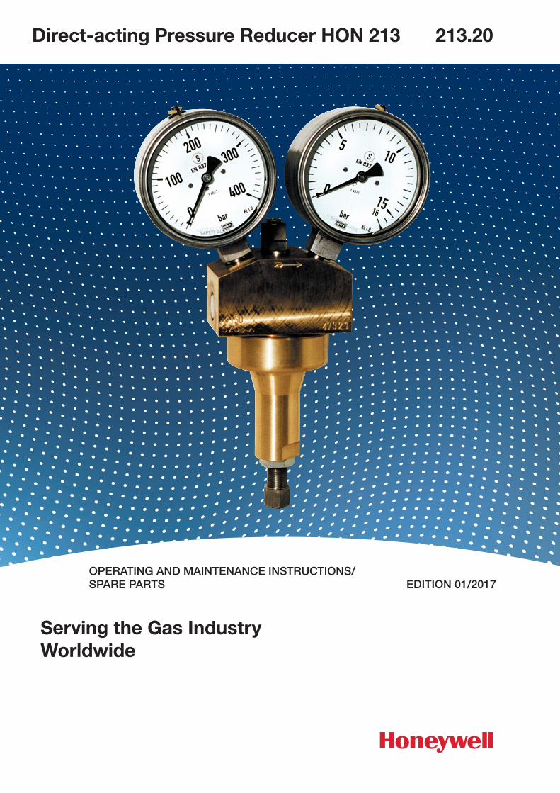
Direct-acting Pressure Reducer HON 213 213.20
Serving the Gas IndustryWorldwide
OPERATING AND MAINTENANCE INSTRUCTIONS/SPARE PARTS EDITION 01/2017
Contents Page
1. General information 3
1.1 Safety information 3
2. Speci�c operating instructions 4
3. Speci�c maintenance instructions 4
3.1 Lubricants 4
4. Spare parts
4.1 Spare parts drawing 5
4.2 Spare parts list 6, 7
4.3 Parts for maintenance purposes 8
213.20 p.02
213.20 p.03
Note
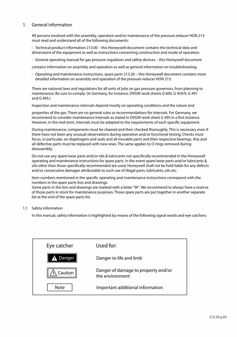
Caution! Danger of damage to property and/or the environment
Important additional information
Eye catcher Used for:
Danger! Danger to life and limb
1. General information
All persons involved with the assembly, operation and / or maintenance of the pressure reducer HON 213 must read and understand all of the following documents:
- Technical product information 213.00 – this Honeywell document contains the technical data and dimensions of the equipment as well as instructions concerning construction and mode of operation.
- General operating manual for gas pressure regulators and safety devices – this Honeywell document
contains information on assembly and operation as well as general information on troubleshooting.
- Operating and maintenance instructions, spare parts 213.20 – this Honeywell document contains more detailed information on assembly and operation of the pressure reducer HON 213.
There are national laws and regulations for all sorts of jobs on gas pressure governors, from planning to maintenance. Be sure to comply. (In Germany, for instance, DVGW work sheets G 600, G 459/II, G 491 and G 495.)
Inspection and maintenance intervals depend mostly on operating conditions and the nature and
properties of the gas. There are no general rules or recommendations for intervals. For Germany, we recommend to consider maintenance intervals as stated in DVGW work sheet G 495 in a �rst instance. However, in the mid-term, intervals must be adapted to the requirements of each speci�c equipment.
During maintenance, components must be cleaned and then checked thoroughly. This is necessary even if there have not been any unusual observations during operation and / or functional testing. Checks must focus, in particular, on diaphragms and seals and all movable parts and their respective bearings. Any and all defective parts must be replaced with new ones. The same applies to O rings removed during disassembly.
Do not use any spare / wear parts and / or oils & lubricants not speci�cally recommended in the Honeywell operating and maintenance instructions for spare parts. In the event spare / wear parts and / or lubricants & oils other than those speci�cally recommended are used, Honeywell shall not be held liable for any defects and / or consecutive damages attributable to such use of illegal parts, lubricants, oils etc.
Item numbers mentioned in the speci�c operating and maintenance instructions correspond with the numbers in the spare parts lists and drawings.Some parts in the lists and drawings are marked with a letter "W". We recommend to always have a reserve of those parts in stock for maintenance purposes. Those spare parts are put together in another separate list at the end of the spare parts list.
1.1 Safety information
In this manual, safety information is highlighted by means of the following signal words and eye catchers:
213.20 p.04
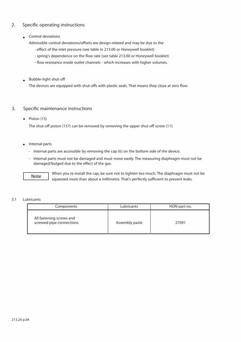
2. Speci�c operating instructions
•
•
•
3.1 Lubricants
Components Lubricants HON part no.
All fastening screws and screwed pipe connections Assembly paste 27091
3. Speci�c maintenance instructions
Control deviations
Admissible control deviations / o�sets are design-related and may be due to the
- e�ect of the inlet pressure (see table in 213.00 or Honeywell booklet)
- spring's dependence on the �ow rate (see table 213.00 or Honeywell booklet)
- �ow resistance inside outlet channels - which increases with higher volumes.
• Bubble-tight shut-o�
The devices are equipped with shut-o�s with plastic seals. That means they close at zero �ow.
Note
Piston (15)
The shut-o� piston (157) can be removed by removing the upper shut-o� screw (11).
Internal parts
- Internal parts are accessible by removing the cap (6) on the bottom side of the device.
- Internal parts must not be damaged and must move easily. The measuring diaphragm must not be damaged / bulged due to the e�ect of the gas.
When you re-install the cap, be sure not to tighten too much. The diaphragm must not be squeezed more than about a millimetre. That's perfectly su�cient to prevent leaks.
29
30
31, 32
33
22
23
24
25
26
27
W 28
20
21
11
12
13
14
15 W
16
17
18
19
1
2
W 3
W 4
5
6
7
8
9
10
A
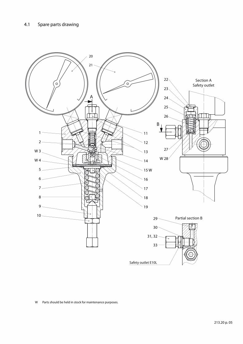
4.1 Spare parts drawing
Section ASafety outlet
B
Partial section B
Safety outlet E10L
213.20 p. 05
W Parts should be held in stock for maintenance purposes.
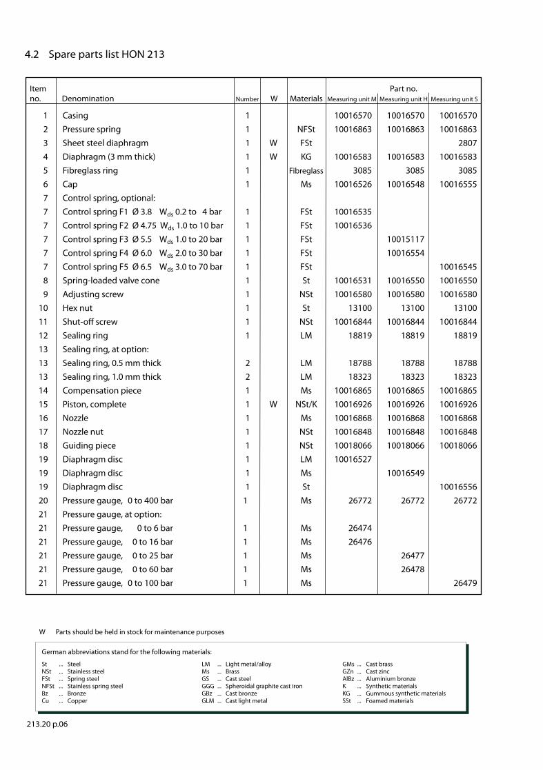
Item Part no.no. Denomination Number W Materials Measuring unit M Measuring unit H Measuring unit S
213.20 p.06
4.2 Spare parts list HON 213
1 Casing 1 10016570 10016570 10016570 2 Pressure spring 1 NFSt 10016863 10016863 10016863 3 Sheet steel diaphragm 1 W FSt 2807 4 Diaphragm (3 mm thick) 1 W KG 10016583 10016583 10016583 5 Fibreglass ring 1 Fibreglass 3085 3085 3085 6 Cap 1 Ms 10016526 10016548 10016555 7 Control spring, optional: 7 Control spring F1 Ø 3.8 Wds 0.2 to 4 bar 1 FSt 10016535 7 Control spring F2 Ø 4.75 Wds 1.0 to 10 bar 1 FSt 10016536 7 Control spring F3 Ø 5.5 Wds 1.0 to 20 bar 1 FSt 10015117 7 Control spring F4 Ø 6.0 Wds 2.0 to 30 bar 1 FSt 10016554 7 Control spring F5 Ø 6.5 Wds 3.0 to 70 bar 1 FSt 10016545 8 Spring-loaded valve cone 1 St 10016531 10016550 10016550 9 Adjusting screw 1 NSt 10016580 10016580 10016580 10 Hex nut 1 St 13100 13100 13100 11 Shut-o� screw 1 NSt 10016844 10016844 10016844 12 Sealing ring 1 LM 18819 18819 18819 13 Sealing ring, at option: 13 Sealing ring, 0.5 mm thick 2 LM 18788 18788 18788 13 Sealing ring, 1.0 mm thick 2 LM 18323 18323 18323 14 Compensation piece 1 Ms 10016865 10016865 10016865 15 Piston, complete 1 W NSt/K 10016926 10016926 10016926 16 Nozzle 1 Ms 10016868 10016868 10016868 17 Nozzle nut 1 NSt 10016848 10016848 10016848 18 Guiding piece 1 NSt 10018066 10018066 10018066 19 Diaphragm disc 1 LM 10016527 19 Diaphragm disc 1 Ms 10016549 19 Diaphragm disc 1 St 10016556 20 Pressure gauge, 0 to 400 bar 1 Ms 26772 26772 26772 21 Pressure gauge, at option: 21 Pressure gauge, 0 to 6 bar 1 Ms 26474 21 Pressure gauge, 0 to 16 bar 1 Ms 26476 21 Pressure gauge, 0 to 25 bar 1 Ms 26477 21 Pressure gauge, 0 to 60 bar 1 Ms 26478 21 Pressure gauge, 0 to 100 bar 1 Ms 26479
W Parts should be held in stock for maintenance purposes
German abbreviations stand for the following materials:
St ... Steel LM ... Light metal / alloy GMs ... Cast brass NSt ... Stainless steel Ms ... Brass GZn ... Cast zinc FSt ... Spring steel GS ... Cast steel AlBz ... Aluminium bronze NFSt ... Stainless spring steel GGG ... Spheroidal graphite cast iron K ... Synthetic materials Bz ... Bronze GBz ... Cast bronze KG ... Gummous synthetic materials Cu ... Copper GLM ... Cast light metal SSt ... Foamed materials
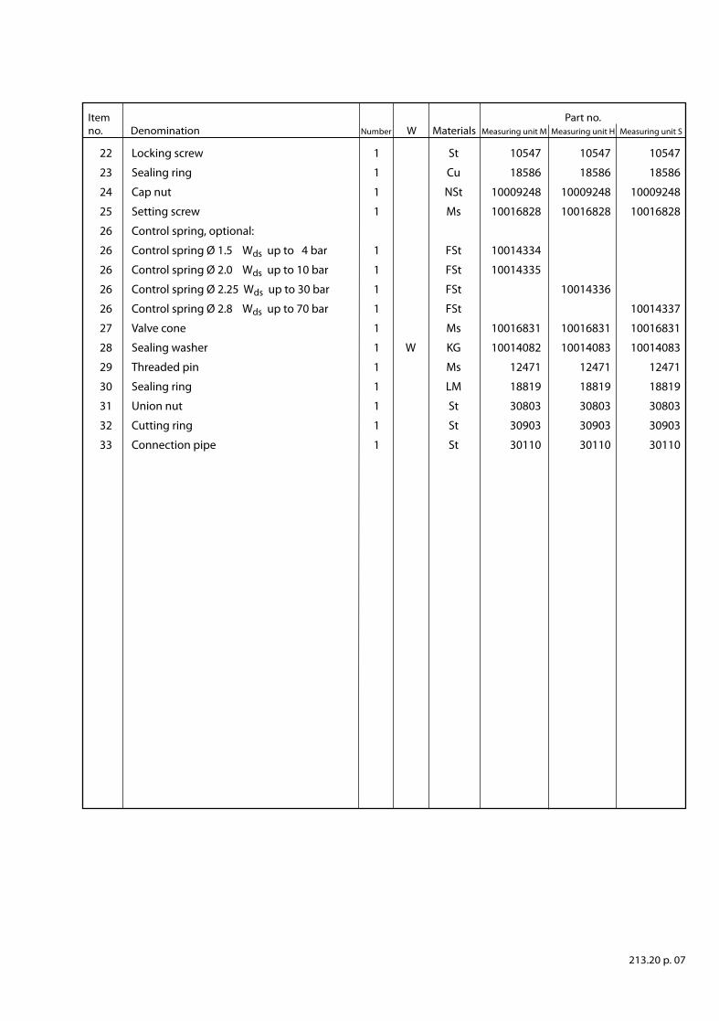
Item Part no.no. Denomination Number W Materials Measuring unit M Measuring unit H Measuring unit S
213.20 p. 07
22 Locking screw 1 St 10547 10547 10547
23 Sealing ring 1 Cu 18586 18586 18586
24 Cap nut 1 NSt 10009248 10009248 10009248
25 Setting screw 1 Ms 10016828 10016828 10016828
26 Control spring, optional:
26 Control spring Ø 1.5 Wds up to 4 bar 1 FSt 10014334
26 Control spring Ø 2.0 Wds up to 10 bar 1 FSt 10014335
26 Control spring Ø 2.25 Wds up to 30 bar 1 FSt 10014336
26 Control spring Ø 2.8 Wds up to 70 bar 1 FSt 10014337
27 Valve cone 1 Ms 10016831 10016831 10016831
28 Sealing washer 1 W KG 10014082 10014083 10014083
29 Threaded pin 1 Ms 12471 12471 12471
30 Sealing ring 1 LM 18819 18819 18819
31 Union nut 1 St 30803 30803 30803
32 Cutting ring 1 St 30903 30903 30903
33 Connection pipe 1 St 30110 30110 30110
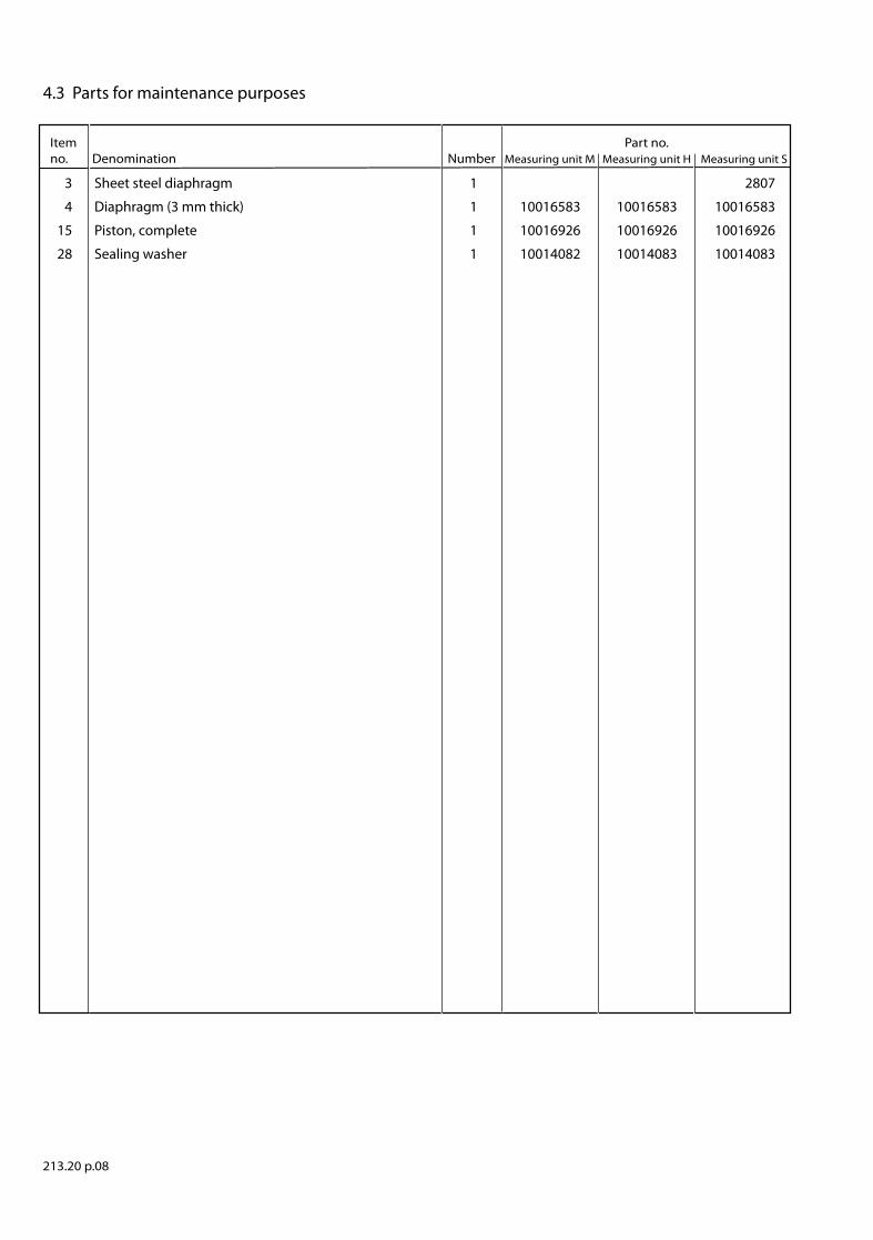
Item Part no. no. Denomination Number Measuring unit M Measuring unit H Measuring unit S
3 Sheet steel diaphragm 1 2807
4 Diaphragm (3 mm thick) 1 10016583 10016583 10016583
15 Piston, complete 1 10016926 10016926 10016926
28 Sealing washer 1 10014082 10014083 10014083
213.20 p.08
4.3 Parts for maintenance purposes

For More Information
To learn more about Honeywell’s
Advanced Gas Solutions, visit
www.honeywellprocess.com or contact
your Honeywell account manager
GERMANY
Honeywell Process Solutions
Honeywell Gas Technologies GmbH
Osterholzstrasse 45
34123 Kassel, Germany
Tel: +49 (0)561 5007-0
Fax: +49 (0)561 5007-107
HON 213.202017-01© 2017 Honeywell International Inc.