direct acceleration feedback control of quadrotor aerial
TRANSCRIPT
HAL Id hal-02494590httpshalarchives-ouvertesfrhal-02494590
Submitted on 28 Feb 2020
HAL is a multi-disciplinary open accessarchive for the deposit and dissemination of sci-entific research documents whether they are pub-lished or not The documents may come fromteaching and research institutions in France orabroad or from public or private research centers
Lrsquoarchive ouverte pluridisciplinaire HAL estdestineacutee au deacutepocirct et agrave la diffusion de documentsscientifiques de niveau recherche publieacutes ou noneacutemanant des eacutetablissements drsquoenseignement et derecherche franccedilais ou eacutetrangers des laboratoirespublics ou priveacutes
Direct Acceleration Feedback Control of QuadrotorAerial Vehicles
Mahmoud Hamandi Marco Tognon Antonio Franchi
To cite this versionMahmoud Hamandi Marco Tognon Antonio Franchi Direct Acceleration Feedback Control ofQuadrotor Aerial Vehicles IEEE International Conference on Robotics and Automation (ICRA 2020)May 2020 Paris France 101109ICRA4094520209196557 hal-02494590
Preprint version final version at httpieeexploreieeeorg IEEE International Conference on Robotics and Automation 2020
Direct Acceleration Feedback Control of Quadrotor Aerial Vehicles
Mahmoud Hamandi1 Marco Tognon1 Antonio Franchi21
Abstractmdash In this paper we propose to control a quadrotorthrough direct acceleration feedback The proposed methodwhile simple in form alleviates the need for accurate estimationof platform parameters such as mass and propeller effective-ness In order to use efficaciously the noisy acceleration mea-surements in direct feedback we propose a novel regression-based filter that exploits the knowledge on the commandedpropeller speeds and extracts smooth platform accelerationwith minimal delay Our tests show that the controller exhibitsa few millimeter error when performing real world tasks withfast changing mass and effectiveness eg in pick and placeoperation and in turbulent conditions Finally we benchmarkthe direct acceleration controller against the PID strategyand show the clear advantage of using high-frequency andlow-latency acceleration measurements directly in the controlfeedback especially in the case of low frequency positionmeasurements that are typical for real outdoor conditions
I INTRODUCTION
Unmanned Aerial Vehicles (UAVs) have become in thelast few years very popular thanks to their versatility andapplicability to many different domains Among the differenttypes of platforms one of the most popular is the quadrotorA quadrotor platform can hover in place which is a desiredfeature for applications such as inspection search amp rescuemonitoring etc
For the purpose of designing the position controller aquadrotor can be considered as a point mass whose ac-celeration is the sum of mass-normalized forces such asgravity wind and a control force produced by the propellersThe control force can be parameterized in two components1) its intensity which is the total thrust provided by the sumof propeller forces and 2) its orientation which normallycorresponds to the vertical axis attached to the vehicle bodyframe In its most common form the motion control of theCenter of Mass (CoM) of a quadrotor vehicle boils down totwo control loops the outer and inner loops (see eg [1][2] and references therein) The outer loop (position control)computes a desired thrust and orientation (roll and pitch)from a blending of the acceleration reference and a feedbackbased on the CoM position and velocity measurements Theinner loop (attitude control) computes the desired torquesto reorient the platform to the desired orientation Finallyboth the desired force and torques are provided to a low
1LAAS-CNRS Universite de Toulouse CNRS Toulouse Francemahmoudhamandilaasfr marcotognonlaasfrantoniofranchilaasfr
2Robotics and Mechatronics lab Faculty of Electrical Engineering Mathe-matics amp Computer Science University of Twente Enschede The Nether-lands afranchiutwentenl
This work was partially funded by the European Unionrsquos Horizon 2020research and innovation programme under grant agreement ID 871479AERIAL-CORE
level module that computes rotational speed of each propellernecessary to reach the calculated thrust and orientation
While each control part is affected by wrongly estimatedparameters and external disturbances this paper focuses onthe improvement of the position control which we shall showto be enough to mitigate disturbances such as uncertain massand external forces in addition to uncertain aerodynamicparameters in the low level motor control loop
To put our controller into perspective we further dividethe position controller into a position feedback loop thatcomputes the desired accelerations based on the measuredand desired states and into a thrust controller that calculatesthe desired thrust based on the desired accelerations thissecond part is commonly implemented in open-loop byapplying an inverse of the platform model To cope withthe non-perfect control of the CoM acceleration due to theopen-loop nature of the thrust controller the most commonstrategy is to make the position feedback loop more robust toinput disturbances and parameter uncertainty Classical solu-tions resort to different robust controllers (integral positionfeedback adaptive control [3] sliding mode [4] MPC [5]etc) or try to compensate for the inaccurate accelerationcontrol using a disturbance observer [6]ndash[8]
Another approach that is gaining popularity in the lit-erature is the Incremental Nonlinear Dynamic Inversion(INDI) [9]ndash[11] which exploits the accelerometer measure-ment to robustify the quadrotor control The controller isbased on an incremental law computed from the Taylorexpansion of the dynamics The robustness of INDI againstexternal disturbances has been proven by real experimentsHowever in spite of its robustness INDI requires the knowl-edge of the input effectiveness (ie knowledge of the massand aerodynamic parameters) and propeller rotational mea-surements In addition INDI low-pass-filters the accelerom-eter measurements this introduces a frequency-dependentdelay and removes high-frequency components that mightbe relevant eg in the presence of impacts or rapid changesof acceleration due eg to fast changes in the mass andpropeller effectiveness
In this paper we propose an alternative solution to theproblem our main idea is rather simple but at the best ofour knowledge it has never been explored in this form in therelated literature Rather than partially relying on the open-loop model inversion we want to transform the thrust controlinto a proper feedback control which is based on the directacceleration measurement To do so we exploit the specificacceleration measurement provided by the accelerometer en-riching the position controller with an acceleration feedbackcompensator The goal is to steer to zero the error between
pRxR
yR
zR
FRxWyW
zW
FW
fR
Fig 1 System model and main variables
the desired acceleration commanded by the position feedbackloop and the measured acceleration coming from the ac-celerometer This idea is clearly inspired by torque-feedback-based joint controller for standard manipulators [12] wherethe electric motor input is commanded in order to steer themeasured torque to the desired one Furthermore we provetheoretically and experimentally that our controller doesnot require the knowledge of the mass propeller rotationalspeed measurements and is robust to large variances inthe aerodynamic parameters Finally to get the most out ofthe accelerometer measurements we introduce a zero delayregression-based multi-notch filter that leverages upon thecommanded propeller speeds to find the signal and noiseprofiles in the accelerometer measurements
The paper is organized as follows In Sec II we modela generic quadrotor system In Sec III we recap the stan-dard outer and inner loop controllers and we present ouraccelerometer-based inner loop controller hereafter referredto as the Direct Acceleration (DA) controller We providea particular remark showing how the high-frequency ac-celeration feedback enhances the performance with respectto a PID controller In Sec V we present the regression-based filter for the estimation of body acceleration andfinally Sec VI shows the experimental results A conclusivediscussion in Sec VII ends the manuscript and additionalexperiments and details are provided in the Appendix
II MODELING
We firstly define a fixed world frame FW with axesxW yW zW and origin OW The position of OW is arbi-trary while xW yW zW are such that zW is aligned withthe opposite direction of the gravity vector g isin R3
To describe the frame of the quadrotor we define a bodyframe FR with axes xRyRzR and origin OR centeredwith the vehicle CoM We consider a quadrotor aerial vehiclemodeled as a rigid body with mass mR isin Rgt0 and positivedefinite inertia matrix JR isin R3times3 (expressed in FR andrelative to OR) The configuration of the vehicle is then givenby the position and orientation of FR with respect to (wrt)FW described by the vector pR isinR3 and the rotation matrixRR isin SO(3) respectively The state of the robot completedby the linear velocity wrt FR and the angular velocity wrtFW expressed in FR denoted by vR isin R3 and ωR isin R3respectively On a quadrotor the motion can be controlledacting on four inputs fR isin R and τR = [τRx τRy τRz]
T isin R3where fR is the magnitude of the thrust force fR = fRzRapplied at OR and parallel to zR and τR is the 3D control
vR
ModelvR
pR
fR
Model Inversion(7)
β+
minus
Thrust Control
PositionFeedbackLoop
vRpd
R(t)
1s
+
+
α
zR
zRω ω
Acc-Based Loop
AttitudeCntrl
MotorCntrl
τR
ω1ω2ω3ω4
Fig 2 Block diagram of the quadrotor controller with the twovariants of the thrust controller
moment expressed in FR An example of the system and itsmain variables is shown in Fig 1
Applying the standard Newton-Euler equations one ob-tains the following vehicle equations of motion
vR =fR
mRminusg+ fe
mR(1)
RR = S(ωR)RR (2)JRωR =minusS(ωR)JRωR +τR (3)
where fe isin R3 is any external force (wind gust modelinaccuracy aerodynamic effects etc) S() is the skewoperator defined as S() R3 rarr R3times3 such that S(x)y =xtimesy for every x isin R3 and y isin R3
The motion control problem addressed here is to designa feedback law for the control inputs fR and τR that steersthe position of the vehicle CoM along a sufficiently smoothdesired trajectory pd
R(t) Rrarr R3 It is well known that fora quadrotor one can also independently control the rotationalong the thrust direction commonly called yaw angle Sincethe accelerometer cannot improve the control of this quantitythe latter is done using standard techniques [1]
III CONTROLLER DESIGN
As already discussed the typical control structure for aquadrotor aerial vehicle is composed of two high level con-trollers (the position controller and attitude controller) andone low level controller that controls the propeller velocitiesIn the following we shall show this standard control lawand how we intend to modify the position control part inorder to enhance the robustness against unknown parametersand external disturbances using the direct accelerometerfeedback For the compactness of the paper we omit thedescription of the attitude controller that calculates desiredtorques from desired orientation (and derivatives) and thedescription of the motor speed allocation we refer to [1][2] for the attitude controller and allocation strategy usedFinally we assume these rotational velocities to be appliedinstantaneously through a low level controller in the ESCdescribed in [13]
A Position feedback loop
The position feedback loop is designed considering thedynamics of the vehicle CoM virtually as a double integrator
pR = vR vR = vR (4)
where vR isinR3 is a controllable virtual input For this linearsystem any stabilizing controller that steers pR(t) to pd
R(t)
Preprint version final version at httpieeexploreieeeorg 2 IEEE International Conference on Robotics and Automation 2020
can be used The simplest implementation is a PD controller
vR = vdR + kPeR + kDeR (5)
where eR = pdRminuspR and kPkD isin Rgt0 are positive scalars
We remark that any other more sophisticated controller canbe used such as PID robust controller sliding mode etcHowever if (4) is verified even the simple PD control law(5) will asymptotically steer pR(t) to pd
R(t)Then the role of the thrust controller and the attitude
controller is to compute the real control inputs fR and τRsuch that (4) is verified
B Classical thrust controller
The classical way to make vR = vR is to apply a partiallyopen-loop controller based on the inversion of the dynamicsIn particular the thrust vector f
R is computed inverting (1)
fR = mR (v
R +g)minusfe (6)
As we showed in Sec II the total thrust vector is controlledby the thrust intensity and the full-body orientation Alongthe current thrust direction zgtR f
R can be instantaneously
applied setting the thrust intensity control input similarto [14]
fR = zgtR fR (7)
A schematic representation of the controller along the thrustdirection is shown in Fig 2 In order to properly apply theother two components (lateral forces) it should be that zR =zR where zR is computed as
zR = fRf
R (8)
where is intended as the Euclidean norm To attain (8)the desired thrust direction together with the desired rotationalong the latter (desired yaw angle) are used as a referenceby the attitude controller that steers zR to zR and the yawangle to the desired one
In the practical implementation of (7) and (6) one typi-cally uses the nominal values of the system parameters suchas the mass mR the gravity g and an estimation of theexternal disturbance fe concurrently it is estimated that thelift coefficient applied in the allocation strategy is constantat its nominal value c f By replacing the nominal values into(6) and placing equation (6) and (7) into (1) we can writethe close-loop dynamics along the thrust direction (the mostimportant one for the quadrotor motion control) as follows
zgtR vR = zgtR
(1
mR
(feminus fe
c f
c f
)minusg+
mRc f
mRc fg+
mRc f
mRc fvR
)(9)
It is clear that if the nominal and estimated quantities areequal to the real values ie mR = mR g = g fe = fe andc f = c f then zgtR vR = zgtR v
R and the control objective is
achieved at least along the thrust direction Nevertheless assoon as there are model uncertainties and estimation errorswhich is the normal situation in practice such a goal is notmet In the next section we shall show how the use of theaccelerometer allows to attain the control objective even inthose non-ideal conditions
C Accelerometer-based thrust controller
The majority of quadrotor platforms are equipped with anInertial Measurement Unit (IMU) including an accelerometerand a gyroscope The two are normally used for the estima-tion of the vehicle attitude [1] [15] Here we shall show howthe acceleration measurement can also be used to make the(partially open) position loop controller a (fully) closed-loopone This allows achieving the control objective (4) even withmodel uncertainties and unknown external disturbances
The accelerometer measurements defined by the vectorwa isin R3 provide the specific acceleration ie
wa =RgtR (vRminusg) (10)
from which one can get a direct measure of the acceleration
vR = g+RRwa (11)
As done in the previous section let us focus on the dynamicsalong the thrust direction To simplify the notation wedefine y = zgtR vR u = zgtR fR = fR a = (c f (mR c f )) andb= zgtR (femRminusg) We can then rewrite (1) along the thrustdirection as
y = au+b (12)
We consider a and b as unknown variables More in gen-eral the quantity a also called input effectiveness includesdifferent sources of uncertainties 1) the mass and 2) thethrust intensity which might be not precisely known Thelatter might even change over time due to aerodynamiceffects eg ground and ceiling effects [16] The quantityb represents any external disturbance applied to the robot(eg wind gusts the additional weight of a load unmodeleddrag etc) including the gravity The control objective is tosteer y to y = zgtR v
R with a and b unknown To attain this
purpose we propose the following controller based on theacceleration input
u = αy+β
inteydt (13)
where ey = y minus y is the acceleration error β isin R andα isin R is an estimation of 1a We shall show that theterm αy improve the control performance if α is a decentapproximation of 1a However if a good estimation of a isnot available α can be set arbitrarily and the controller isstill applicable A schematic representation of the controlleralong the thrust direction is shown in Fig 2 We can verifythat ey has a stable behavior analyzing its dynamics
ey = yminus (au+ au+ b) =minusaβey + ayminus auminus b (14)
where a = 1minus aα The equilibrium point is clearly ey =(ayminus auminus b
)(aβ ) and is asymptotically stable if aβ gt 0
while assuming a to be zero Even if a is unknown its sign isnormally known and the sign of β can be chosen accordinglyWithout loss of generality we can assume that a gt 0 Theequilibrium point ey is then asymptotically stable for anyβ gt 0 a and b
Remark 1 Notice that if y = a = b = 0 as in many ofthe practical cases the error will asymptotically converge tozero One can also observe that knowing precisely the input
Preprint version final version at httpieeexploreieeeorg 3 IEEE International Conference on Robotics and Automation 2020
effectiveness (ie α = 1a a = 0) the part of the error dueto y vanishes It is not surprising that knowing the feed-forward term will improve the performance Nevertheless weremark that for the DA controller a precise knowledge of ais not actually needed In fact increasing β one can makethe steady-state error ey very small independently of theunknown parameter and disturbance Unfortunately β cannotbe arbitrarily large otherwise u will be too large and thesystem will not be able to provide the corresponding u
The above remark is validated experimentally1
IV DISCUSSION ON THE COMPARISON WITH PIDLet us assume that a standard PD position feedback loop
controller is applied We can then replace (5) into (13) wherewe recall that y = zgtR v
R
u = α
(vd
Rt + kPeRt + kDeRt
)+β
(eprimeRt + kDeprimeRt + kP
inteRtdt
) (15)
where vdRt = z
gtR v
dR eRt = z
gtR eR and similarly for its deriva-
tives Furthermore eprimeRt =int(vd
Rt minus vRt)dt and eprimeRt =int(vd
Rt minusvRt)dt with vRt = zgtR vR and similarly for its derivativesWhile it is clear that (15) resembles a PID it turns outfrom the experimental comparisons (see Fig 5) that the stepresponse against an external disturbance can be made fasterfor the proposed acceleration-based thrust controller plus aPD position feedback loop controller when compared to thePID controller The experiment has been conducted with thetwo controller gains tuned at best2
To investigate this discrepancy we notice that the PIDin (15) relies on the high frequency accelerometer measure-ments 1 [KHz] in addition to the low frequency position andvelocity measurements required in a normal PID
In the following we analyze a simplified system thatstill encapsulates the main properties in order to betterexplain why high-frequency acceleration feedback showsbetter stability than an equivalent controller based on slowersampled measurements Let us consider the dynamic system
x1 = x2 x2 = u (16)
where u = minusk1x1 minus k2x2 is a simple PD controller withk1k2 isin Rgt0 For this system we analyze two cases
1) both x1 and x2 in u are sampled with period T isin Rgt02) only x1 in u is sampled with period T while x2 is
sampled at a much higher frequency such that it canbe considered continuous
In our parallelism case 1) corresponds to the standard PIDbased on low-sampled measurements while case 2) corre-sponds to the proposed acceleration-based thrust controller
For case 1) from the theory of digital control [17] it iswell known that the proportional gain k1 cannot be increasedarbitrarily (aiming at a better performance) On the contrary
1The results and details of these experiments showing the robustnessto the choice of a and the advantage of knowing accurately the inputeffectiveness are presented in the Appendix
2We consider the best gains as the maximum gains that preserve thestability of the system Higher gains would make the system unstable
its maximum value is bounded depending on the samplingtime T The higher T the lower k1 has to be in order toguarantee stability
For case 2) the measurement of x2 can be consideredcontinuous time with respect to the sampling of x1 Thenthe control input u can be written as
u =minusk1x1minus k2x2 (17)
where x1 is the sampled measurement of x1 In thecontinuous-time we can write x1(t) = x1(t)minus∆x1(t) where∆x1(t) isin R is the error at time t due to the sampling of thesignal Notice that ∆x1(t) = 0 if t = iT for a certain i Let usnow consider the following Lyapunov function
V (x1x2) =12(k1x2
1 + x22) (18)
which is clearly positive semi-definite and V (x1x2) = 0 ifx1 = x2 = 0 The time derivative of V (x1x2) is
V (x1x2) = k1x1x2 + x2 (minusk1x1minus k2x2)
= x2 (k1∆x1minus k2x2) (19)
Considering the Taylor approximation of ∆x1 around the timeiT for a certain i we can bound ∆x1 with x2T Therefore itis easy to verify that
V (x1x2)leminusx2 (k2minus k1T )x2 (20)
which is negative semi-definite if k2 is chosen such that k2minusk1T gt 0 Using the LaSalle principle [18] we can prove thestability of the system This implies that whatever is thesampling period of x1 one can choose k1 arbitrarily largeand then k2 such that k2 gt k1T For case 2) thanks to the highsampling frequency of x2 one can obtain a fast convergenceof the state to zero independently from the sampling rateof x1
V FILTERING OF THE BODY ACCELERATION
The raw accelerometer measurements are practically un-usable due to high frequency noise mostly coming from thevibrations of the propellers The most common techniqueto extract the body acceleration is to use a low-pass filterwhich introduces frequency dependent delay and phase shiftand can remove high frequency components of the signalMoreover low-pass filters are linear filters that attenuate highfrequency noise instead of removing them As such highamplitude noise can still show up in the filtered signal
We designed an adaptive and regression-based notch filterthat allows to reject multiple frequency components withoutadding any delay or phase shift and that at the same timeremains simple to implement In addition as our filter isregression-based it is able to find the amplitude of thenoise signal and remove it completely from the accelerometersignal while a linear filter can only attenuating it
Considering what has been presented so far we canmodify the ideal accelerometer model in (10) into
wa =SvR +δ+σ (21)
where SvR = RgtR (vRminusg) is the specific acceleration ofthe main body the one that we would like to estimateδ represents the vibrations induced by spinning propellers
Preprint version final version at httpieeexploreieeeorg 4 IEEE International Conference on Robotics and Automation 2020
and σ represents all the additional noise assumed gaussiandistributed with zero mean
Let us consider a certain time window of N isin Ngt0acceleration samples wa(t) = [wgta (t) w
gta (tminusT ) wgta (tminus
NT )]gt isin R3N where T isin Rgt0 is the sampling period Thefirst step to estimate SvR(t) given wa(t) is to model thecomponents of wa For the specific acceleration we use aTaylorpolynomial approximation
SvR(t) =p
sumi=0
θvit i (22)
where p isin Ngt0 is the degree of the polynomial which hasto be chosen a priori and depends on the variability signalSvR over the time window [tminusNT t] (as a rule of thumb ingeneral the larger the time window the larger p) and θvi isinRis the generic unkown i-th coefficient of the polynomial tobe estimated
We model δ as a sum of q shifted sinusoidal functions
δ(t) =q
sumj=0
θδ j sin(ωδ jt +φδ j) (23)
where θδ j isin R and φδ j isin R are the amplitude and phaseshift of the generic j-th sinusoidal again to be estimatedWe assume that the pulsation ωδ j of the j-th sinusoidal isknown since it is directly linked to the spinning frequencyof the propellers and its harmonics There are several waysto choose q and ωδ j according to the current frequency ofthe propellers In general it is a good practice to chooseq as small as possible to avoid over-fitting Following thisguideline we choose q = 4 taking ωδ1 and ωδ2 as theminimum spinning frequency among the propellers (in theconsidered time window) and its first harmonic respectivelySimilarly we take ωδ3 and ωδ4 as the maximum spinningfrequency among the propellers (in the considered timewindow) and its fist harmonic respectively
Noticing that sin(ωδ jt +φδ j) = cos(φδ j)sin(ωδ jt) +sin(φδ j)cos(ωδ jt) we can rewrite (23) as
δ(t) =q
sumi=0
θc j sin(ωδ jt)+θs j cos(ωδ jt) (24)
which is now linear in the new parameters θc j = θδ j cos(φδ j)and θs j = θδ j sin(φδ j)
Given the accelerometer measurements wa we can obtainan estimation of the specific acceleration S ˆvR identifying theparameters θvi for i= 1 p and θs jθc j for j = 1 q bysimple linear regression Notice that the minimum require-ment is N ge p+2q In addition in order to clearly identifyall the sinusoidal components it is desirable that wa containsat least a full period of the slowest sinusoidal signal
Finally in order to remove the additional noise σ (thatwe did not model in the regression) from S ˆvR we use adiscrete adaptive high-bandwidth low-pass filter Let S ˆvR[k]be the regressed estimation of the specific acceleration atthe discrete-time tk = kT where k isin N+ Then the adaptivehigh-bandwidth low-pass filter can be expressed as
S ˆvR f [k] = (1minusκ[k])S ˆvR f [kminus1]+κ[k]S ˆvR[k] (25)
Fig 3 The quadrotor picking up an unknown mass with a hook-and-loop Left the platform descending to pick up the object Rightthe platform ascending after it had fastened and picked up theobject
where S ˆvR f [k] is the low-pass filtered value of S ˆvR[k] andκ[k] is an adaptive gain computed as
κ[k] = min
(1
∣∣∣∣∣S ˆvR[k]vth
∣∣∣∣∣) (26)
where || represents the absolute value S ˆvR[k] is an esti-mation of the rate of change of SvR calculated from theregressed derivative of S ˆvR and vth is a threshold rate suchthat if S ˆvR[k] ge vth the filter would behave as a zero-phaseall-pass filter
The chosen adaptive gain allows the filter to have lowbandwidth when SvR is slowly varying (a case in whichthe effect of σ is more visible) thus effectively filteringthe noise and a very high bandwidth when SvR is rapidlyvarying (a case in which the effect of σ is almost negligible)to obtain non-delayed tracking3
VI EXPERIMENTAL RESULTS
The validation experiments have been conducted with aquadrotor platform with software running on-board in real-time The experiments are conducted in door with conditionsemulating outdoor settings For more details about the hard-ware software and configurations used we refer the readerto the Appendix
A Use of DA in Two Practically Relevant Scenarios
In this section we assess the performance of the proposedDA controller while completing two real world tasks in-volving unknown and time-varying changes in the quadro-tor dynamical model i) hook-and-loop fasten and pick anunknown-mass object and ii) take-off and maneuver in aair-turbulent environment 4
In the first experiment shown in Fig 3 the platformis commanded to pick up an object whose 04 [Kg] massis unknown to the controller Despite the unknown massthe platform was able to follow the desired position whileapproaching and lifting the object The recorded error alongboth trajectories is less than 0008 [m]
In the second experiment shown in Fig 4 the platformflies underneath a flying hexarotor due to the configuration
3The proposed filter is compared against a second-order Butterworth filterthe comparison results are presented in the Appendix
4Detailed results of these experiments are presented in the Appendix
Preprint version final version at httpieeexploreieeeorg 5 IEEE International Conference on Robotics and Automation 2020
Fig 4 The quadrotor flying stabiliy beneath a 25 [Kg] hexarotor
of its propellers the hexarotor creates a turbulent environ-ment for the quadrotor Despite the turbulence the quadrotoris able to lift off ground hover in place then approach thehexarotor and retract back to its original position with anerror less than 001 [m] throughout its flight
B Comparing the Best DA and PID Performances
We assess the performance of DA against a PID controllerwith equivalent gains as described in (15) Gains kP andkD were tuned to ensure a desirable transient performanceand a near zero steady state error kP = 275 and kD = 18The acceleration gain β was varied to study its effect onthe performance of each controller as seen from (13) theincrease in β increases the reactiveness of the controller to eyand correspondingly its reactiveness to external disturbances
Figure 5 shows a statistical representation of repeatedexperiments demonstrating a comparison between the DAcontroller and a PID following a step disturbance of 4 [N] ndashequivalent to 0407 [Kg] ie 40 of the platform massThis experiment highlights the performance of the controllersin scenarios such as sudden lifting of an unknown mass ora very quick change in the aerodynamic properties of theplatformrsquos actuators due eg to a sudden wind gust Thesame figure shows the difference between the controllers fordifferent values of the acceleration gain β
We observe that both controllers can achieve a zero steadystate error before and after the step disturbance howeverwith varying transient performances As we increase β bothcontrollers reach steady state in a shorter time and achieve asmaller maximum error post the step response these last twoobservations suggest that an increase in β induces a fasterreaction to external disturbances
We can also observe from Fig 5 that the performanceof both controllers is similar for the same β with the PIDlagging slightly from the DA controller However we cansee that at β = 4 the PID controller lets the error oscillateand eventually diverge while the DA controller can stillachieve stable flight At β = 12 the DA controller showssmall oscillations ndash while still achieving a stable flight ndashwith a maximum error of 2 [cm] while the PIDrsquos best errorwas around 4 [cm] with β = 3
C Dynamic Maneuver
Finally we assess the performance of DA while per-
Fig 5 Step response of DA vs PID following a 4 [N] ( 0407 [Kg])step function while varying β with lines of the same colorcorresponding to the same β solid lines to DA and dashed linesto PID Each of the plots show the statistics of 3 identical flightswith the exception of the PID at β = 4 showing only one flight toavoid possible crashes
forming high speed maneuvers While our system does notameliorate the attitude controller but rather is designed tobe robust to external disturbances we conduct these flightsto show that the lateral motion is not deteriorated by ourcontrollerTo this end we fly our controller in a lemniscate patern witha radius of 2 [m] and at a maximum speed of 28 [msminus1]During these flights our controller follows the desired statedefined by the equation of the lemniscate with the corre-sponding derivatives The controller exhibits a maximumerror of 01 [m] along the trajectory which is equivalent tothe PID error for the same flight More details regarding thisflight can be found in the Appendix
VII CONCLUSIONS
In this work we proposed a novel quadrotor controllerconcept based on direct acceleration (DA) feedback Thecontroller does not require any knowledge of the platformrsquosmass or propeller efficiency while can still benefit from suchknowledge
In addition we proposed a new regression-based methodto filter the IMU signal which uses the information aboutthe commanded propeller speed and extracts vibration-freebody acceleration We show that our regression based methodremoves the vibrations from the signal with a smaller delaythan classical low pass filters
We conducted an experimental campaign to demonstratethe performance of the new controller in various challengingscenarios and compared its performance to a well tuned PIDDuring these experiments the DA controller exhibits moreaccurate position tracking conditions in reaction to suddendisturbances
In the future we intend to improve the DA controller by in-cluding possible compensation also of the lateral acceleration
Preprint version final version at httpieeexploreieeeorg 6 IEEE International Conference on Robotics and Automation 2020
05 055 06 065 07
-3
-25
-2
-15
-1
01 015 02 025 03
-05
-04
-03
-02
-01
Fig 6 Comparison of different types of filters on the raw ac-celerometer data waz where S ˆvR is the output of the proposedregression-based filter S ˆvRbutt30 is the output of a second-orderButterworth filter with cutoff frequency 30 [Hz] and S ˆvRbutt13 isthe output of a second-order Butterworth filter with cutoff frequency13 [Hz]
and the handling of substantial biases in the measurementdata by including pre-integration of the positional error inaddition to the existing post-integration
APPENDIX
This appendix presents details the experimental setup andextra experimental results
A Regression Based notch filter
In Fig 6 we compared the estimated specific accelerationusing different techniques 1) the proposed regression-basedfilter defined by the symbol S ˆvR 2) a second-order Butter-worth filter with cutoff frequency 30 [Hz] (same setup usedin [9]) defined by the symbol S ˆvRbutt30 3) a second-orderButterworth filter with cutoff frequency 13 [Hz] definedby the symbol S ˆvRbutt13 From Fig 6 it is evident that theproposed regression-based filter is the one able to suppressthe vibrations (see Fig 6 on the right) while minimizing thedelay when the signal changes rapidly (see Fig 6 on theleft) On the other hand using a second-order Butterworthfilter with cutoff frequency 30 [Hz] the delay with respectto the real signal is small (although still larger than usingthe regression-based filter) but the vibrations are still there(see Fig 6 on the right) In order to almost suppress thevibrations with a second-order Butterworth filter one has toset a cutoff frequency of 13 [Hz] However the delay becomesmuch larger
B Experimental Setup
The validation experiments have been conducted witha quadrotor platform weighting about 1 [Kg] The vehi-cle is endowed with an IMU which exports the raw ac-celerometer and gyroscope measurements at 1 [KHz] andfour brushless motor controllers (BLDC ESC) regulatingthe propeller speed using an in-house developed closed-loop speed controller [13] A motion capture system readsthe position and orientation of the vehicle and a UKFcomponent performs the sensor fusion to retrieve the fullstate of the platform To ensure consistency with the typicalsensor frequencies available in an outdoor setting endowed
Fig 7 showing error distribution of the platform while taking offand landing with a wrong c f or α
with eg a standard vision-based localization system wesample the position and velocity measurements from theUKF at 20 [Hz] Most of the software components (includingthe controller) have been developed in C++ and run onan onboard PC (odroid XU4) at 1 [KHz] As for most ofthe robotics software at LAAS-CNRS software componentshave been developed using GenoM3 [19] a code generatorand formal software component description language thatallows assembling middleware-independent components ina modular system Most of this software is available on theopenrobots repository at httpsgitopenrobotsorgprojectstelekyb3
C Flight with unknown parameters
This section shows experiments where the platform takesoff and lands with different values of the lift coefficientc f and α provided to the attitude controller and the thrustcontroller respectivelybull In the first flight we vary α isin [022][Kg] while its
nominal value is 1a = 1[Kg]
bull In the second flight we vary the estimated lift coeffi-cient c f isin [45eminus485eminus4][NHz2] while its identifiednominal value is c f = 65eminus4[NHz2]
Fig 7 shows the distribution of the platformrsquos error whilefollowing the above maneuvre with the chosen parametersThe figure shows that the platform is able to fly for thegiven α and c f range We note that the tested c f range isone that might be encountered during regular flights (suchas ground effect [20]) however we acknowledge that ourcontroller does not guarantee stability for larger variances inc f due to the presence of the attitude controller In additionwe note from Fig 7 that the performance improves if α isan exact estimate of 1
a however the controller is still stableeven when α is set arbitrarily as explained earlier
D Use of DA in Two Practically Relevant Scenarios
Fig 8 shows the actual-vs-desired quadrotor altitudesbefore and after hook-and-loop fastening and picking up an
Preprint version final version at httpieeexploreieeeorg 7 IEEE International Conference on Robotics and Automation 2020
Fig 8 position tracking of the quadrotor before and after hook-and-loop fasten and pick up of an object whose 02 [Kg] mass isunknown to the controller
Fig 9 position tracking of the quadrotor flying beneath a 25 [Kg]hexarotor The plot shows a lift off phase followed by a hoverphase a maneuvre phase and finally another hover phase Duringthe first 25 [s] the platform follows a safety procedure imposing aramp on the motor speeds irrespective of the controller commands
object whose 04 [Kg] mass is unknown to the controllerThe top surface of the object is taken as a reference pointThe platform is commanded to go below the object surfaceas seen in the hook-and-loop fastening and pick up sectionof Fig 8 This experiment shows that while the weightof the object is unknown to the controller and there is aphase in which the motion is even hindered the platformrsquosperformance is smooth stable and indistinguishable beforeand after the pick up with less than 0008 [m] error in bothphases
Fig 9 shows the performance of the DA in the presenceof turbulence created by flying near ground and underneath aflying hexarotor weighting about 25 [Kg] The platform firstlifts off from ground and hovers in place then it increases its
Fig 10 position tracking of the quadrotor while following a highspeed lemniscate maneuvre
altitude to approach the bottom of the hexarotor and then itgoes back to hover in the previous altitude The DA controllerin Fig 9 shows complete resilience to the existing turbulencewhile following its desired trajectory with less than 001 [m]maximum error It has to be noted that during take offthere is an initial error caused by the quadrotorrsquos safetystarting procedure which imposes the motor speeds to followa 25 [s] saturation ramp from 0 to 100 which prevents theexecution of the DA commanded forces The DA controllerlets the platform behave smoothly and stably despite suchadditional unmodeled obstruction to the actuation system
E Lemniscate Maneuvre
Fig 10 shows the performance of the DA controller whilefollowing an agile lemniscate maneuvre The lemniscate hasa 2 [m] radius and with a maximum velocity in the centerat 28 [msminus1] and 2 [msminus1] with a 28 [msminus2] accelerationat the edges The lemniscate is enforced by calculating thedesired position velocity acceleration jerk and snap at eachpoint
The maximum error norm recorded along the trajectory is01 [m]
REFERENCES
[1] R Mahony V Kumar and P Corke ldquoMultirotor Aerial VehiclesModeling Estimation and Control of Quadrotorrdquo IEEE Robotics ampAutomation Magazine vol 19 no 3 pp 20ndash32 2012
[2] M Faessler A Franchi and D Scaramuzza ldquoDifferential flatnessof quadrotor dynamics subject to rotor drag for accurate tracking ofhigh-speed trajectoriesrdquo IEEE Robotics and Automation Letters vol 3no 2 pp 620ndash626 2018
[3] G Antonelli E Cataldi F Arrichiello P Robuffo Giordano S Chi-averini and A Franchi ldquoAdaptive trajectory tracking for quadrotorMAVs in presence of parameter uncertainties and external distur-bancesrdquo IEEE Trans on Control Systems Technology vol 26 no 1pp 248ndash254 2018
[4] L Besnard Y B Shtessel and B Landrum ldquoQuadrotor vehiclecontrol via sliding mode controller driven by sliding mode disturbanceobserverrdquo Journal of the Franklin Institute vol 349 no 2 pp 658ndash684 2012
Preprint version final version at httpieeexploreieeeorg 8 IEEE International Conference on Robotics and Automation 2020
[5] K Alexis G Nikolakopoulos and A Tzes ldquoSwitching model predic-tive attitude control for a quadrotor helicopter subject to atmosphericdisturbancesrdquo Control Engineering Practice vol 19 no 10 pp 1195ndash1207 2011
[6] B Yuksel C Secchi H H Bulthoff and A Franchi ldquoAerial physicalinteraction via IDA-PBCrdquo The International Journal of RoboticsResearch vol 38 no 4 p 403421 2019
[7] M Ryll G Muscio F Pierri E Cataldi G Antonelli F Caccav-ale D Bicego and A Franchi ldquo6D interaction control with aerialrobots The flying end-effector paradigmrdquo The International Journalof Robotics Research vol 38 no 9 pp 1045ndash1062 2019
[8] T Tomic C Ott and S Haddadin ldquoExternal wrench estimationcollision detection and reflex reaction for flying robotsrdquo IEEE Transon Robotics vol 33 no 6 pp 1467ndash1482 2017
[9] E Tal and S Karaman ldquoAccurate tracking of aggressive quadrotortrajectories using incremental nonlinear dynamic inversion and differ-ential flatnessrdquo in 2018 IEEE Conference on Decision and Control(CDC) IEEE 2018 pp 4282ndash4288
[10] E J Smeur Q Chu and G C de Croon ldquoAdaptive incrementalnonlinear dynamic inversion for attitude control of micro air vehiclesrdquoJournal of Guidance Control and Dynamics vol 38 no 12 pp 450ndash461 2015
[11] E J Smeur G C de Croon and Q Chu ldquoCascaded incrementalnonlinear dynamic inversion for mav disturbance rejectionrdquo ControlEngineering Practice vol 73 pp 79ndash90 2018
[12] D Vischer and O Khatib ldquoDesign and development of high-performance torque-controlled jointsrdquo IEEE Trans on Robotics andAutomation vol 11 no 4 pp 537ndash544 1995
[13] A Franchi and A Mallet ldquoAdaptive closed-loop speed control ofBLDC motors with applications to multi-rotor aerial vehiclesrdquo in 2017IEEE Int Conf on Robotics and Automation Singapore May 2017pp 5203ndash5208
[14] T Lee M Leoky and N H McClamroch ldquoGeometric tracking controlof a quadrotor UAV on SE(3)rdquo in 49th IEEE Conf on Decision andControl Atlanta GA Dec 2010 pp 5420ndash5425
[15] P Martin and E Salaun ldquoThe true role of accelerometer feedbackin quadrotor controlrdquo in 2010 IEEE Int Conf on Robotics andAutomation Anchorage AK May 2010 pp 1623ndash1629
[16] C Powers D Mellinger A Kushleyev B Kothmann and V KumarldquoInfluence of aerodynamics and proximity effects in quadrotor flightrdquoin Experimental robotics Springer 2013 pp 289ndash302
[17] I D Landau and G Zito Digital control systems design identificationand implementation Springer Science amp Business Media 2007
[18] H K Khalil Nonlinear Systems 3rd ed Prentice Hall 2001[19] A Mallet C Pasteur M Herrb S Lemaignan and F Ingrand
ldquoGenom3 Building middleware-independent robotic componentsrdquo2010 IEEE International Conference on Robotics and Automation pp4627ndash4632 2010
[20] D D C Bernard M Giurato F Riccardi and M Lovera ldquoGroundeffect analysis for a quadrotor platformrdquo in Advances in AerospaceGuidance Navigation and Control Springer 2018 pp 351ndash367
Preprint version final version at httpieeexploreieeeorg 9 IEEE International Conference on Robotics and Automation 2020
- INTRODUCTION
- MODELING
- CONTROLLER DESIGN
-
- Position feedback loop
- Classical thrust controller
- Accelerometer-based thrust controller
-
- Discussion on the Comparison with PID
- FILTERING OF THE BODY ACCELERATION
- EXPERIMENTAL RESULTS
-
- Use of DA in Two Practically Relevant Scenarios
- Comparing the Best DA and PID Performances
- Dynamic Maneuver
-
- CONCLUSIONS
- Appendix
-
- Regression Based notch filter
- Experimental Setup
- Flight with unknown parameters
- Use of DA in Two Practically Relevant Scenarios
- Lemniscate Maneuvre
-
- References
-
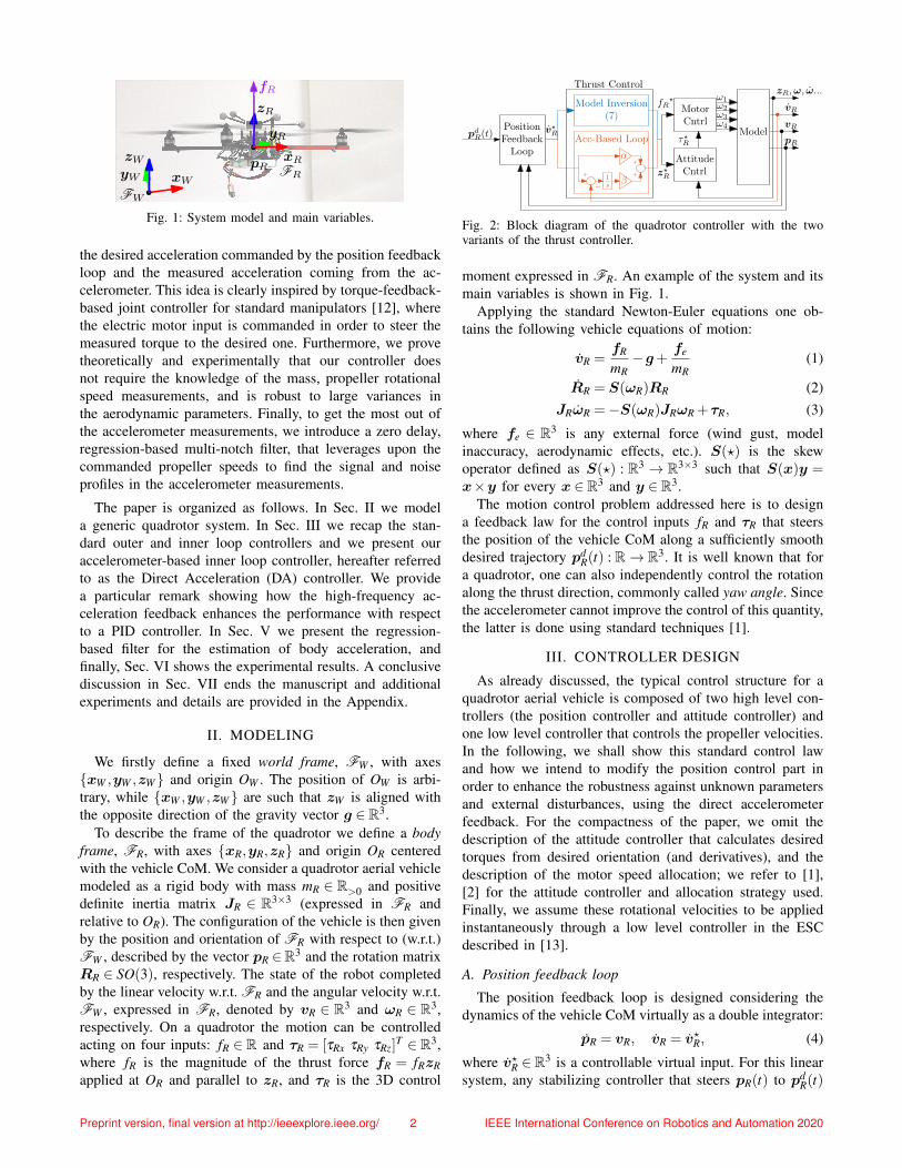
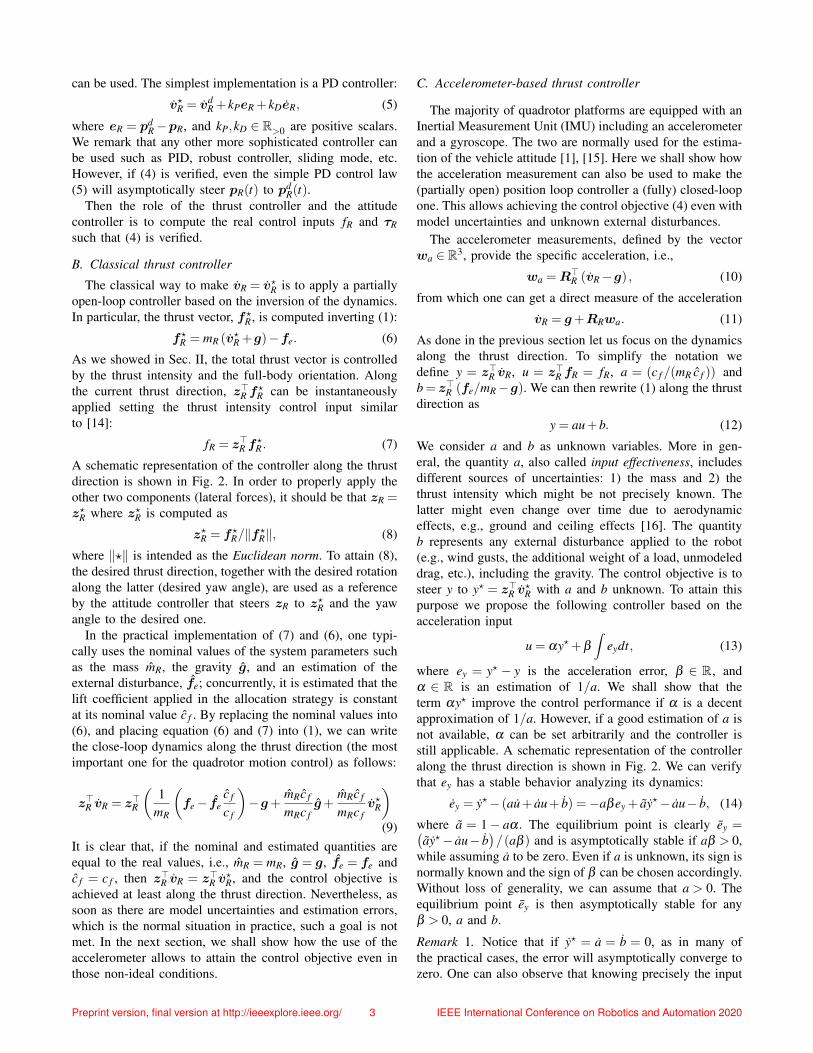
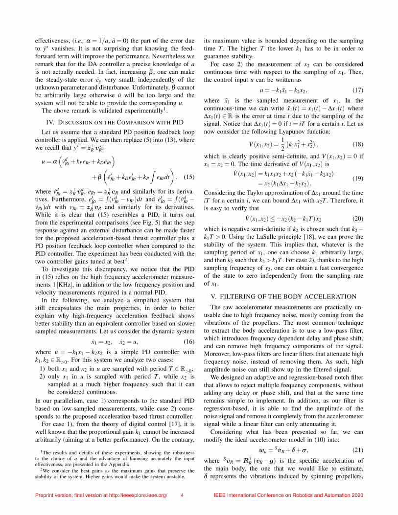
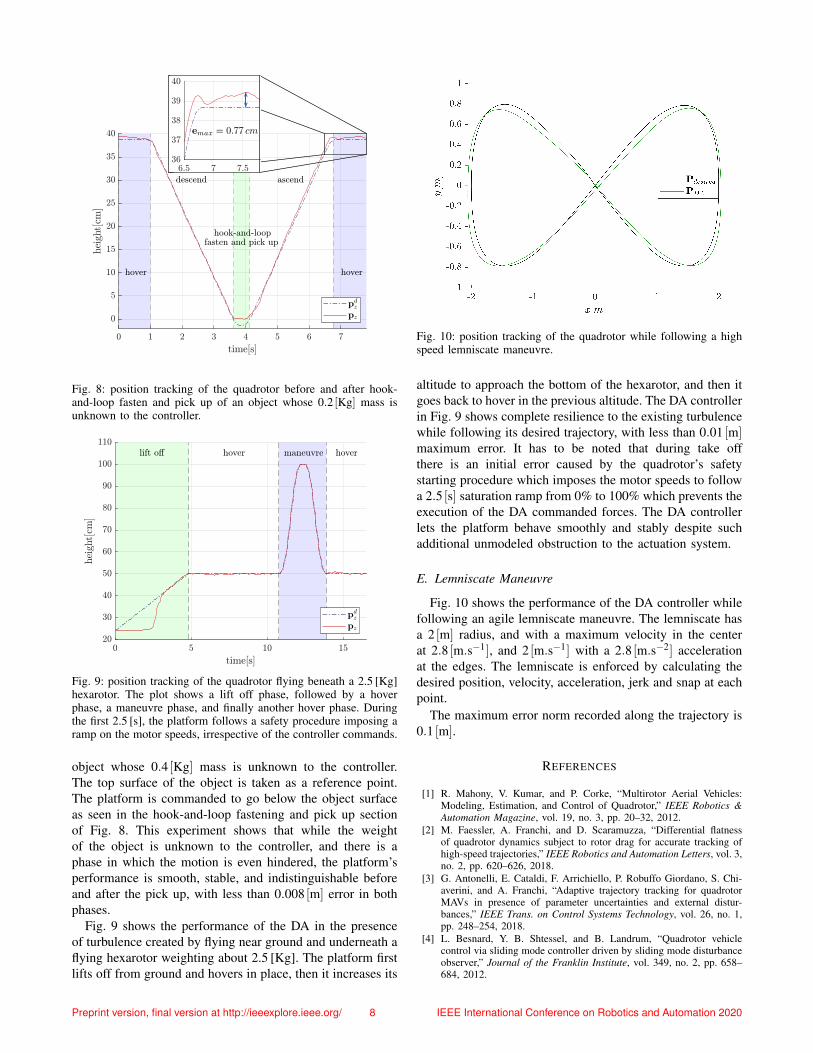