design and control of a quadrotor unmanned aerial vehicle
TRANSCRIPT
NOTE TO USERS
Page(s) not included in the original manuscript are unavailable from the author or university. The
manuscript was microfilmed as received
IV & V
This reproduction is the best copy available.
UMI


u Ottawa L'Universite canadienne
Canada's university
FACULTE DES ETUDES SUPERIEURES 1 ^ = 1 FACULTY OF GRADUATE AND ET POSTOCTORALES U Ottawa POSDOCTORAL STUDIES
L'Univeisite canadienne Canada's university
Sayed Ali Raza auteur'DETATHE^
M.A.Sc. (Electrical and Computer Engineering)
School of Information Technology and Engineering "TacuITTECO^
Design and Control of a Quadrotor Unmanned Aerial Vehicle
TITRE DE LA THESE / TITLE OF THESIS
W. Gueaieb DIRECTEUR (DIRECTRICE) DE LA THESE / THESIS SUPERVISOR
CO-DIRECTEUR (CO-DIRECTRICE) DE LA THESE / THESIS CO-SUPERVISOR
V. Groza P- Liu (Carleton Univeristy)
Gary W. Slater Le Doyen de la Faculte des etudes superieures et postdoctorales / Dean of the Faculty of Graduate and Postdoctoral Studies
Design and Control of a Quadrotor Unmanned Aerial Vehicle
by
Syed Ali Raza
Thesis submitted to the Faculty of Graduate and Postdoctoral Studies
In partial fulfillment of the requirements For the M.A.Sc. degree in
Electrical and Computer Engineering
School of Information Technology and Engineering Faculty of Engineering University of Ottawa
(c) Syed Ali Raza, Ottawa, Canada, 2010

1 * 1 Library and Archives Biblioth&que et Canada Archives Canada
Published Heritage Direction du Branch Patrimoine de l'6dition
395 Wellington Street Ottawa ON K1A 0N4 Canada
395, rue Wellington Ottawa ON K1A 0N4 Canada
Your file Votre reference ISBN: 978-0-494-61280-4 Our file Notre r6f6rence ISBN: 978-0-494-61280-4
NOTICE:
The author has granted a non-exclusive license allowing Library and Archives Canada to reproduce, publish, archive, preserve, conserve, communicate to the public by telecommunication or on the Internet, loan, distribute and sell theses worldwide, for commercial or non-commercial purposes, in microform, paper, electronic and/or any other formats.
AVIS:
L'auteur a accorde une licence non exclusive permettant a la Bibliotheque et Archives Canada de reproduire, publier, archiver, sauvegarder, conserver, transmettre au public par telecommunication ou par I'lnternet, preter, distribuer et vendre des theses partout dans le monde, a des fins commerciales ou autres, sur support microforme, papier, electronique et/ou autres formats.
The author retains copyright ownership and moral rights in this thesis. Neither the thesis nor substantial extracts from it may be printed or otherwise reproduced without the author's permission.
L'auteur conserve la propriete du droit d'auteur et des droits moraux qui protege cette these. Ni la these ni des extraits substantiels de celle-ci ne doivent etre imprimes ou autrement reproduits sans son autorisation.
In compliance with the Canadian Privacy Act some supporting forms may have been removed from this thesis.
While these forms may be included in the document page count, their removal does not represent any loss of content from the thesis.
Conformement a la loi canadienne sur la protection de la vie privee, quelques formulaires secondaires ont ete enleves de cette these.
Bien que ces formulaires aient inclus dans la pagination, il n'y aura aucun contenu manquant.
• • I
Canada
Abstract
This research work is focused on the different steps of designing, building, simulating, and testing an intelligent flight control module for an increasingly popular unmanned aerial robot vehicle (UAV), known as a quadrotor. Also an in-depth view of the modeling of the kinematics, dynamics, and control of such an interesting UAV is presented. Eventually, a quadrotor UAV test-bed is built from scratch using custom off-the-shelf components.
In order to achieve autonomous flight, fuzzy logic is adopted for building the flight controller of the quadrotor. It has been witnessed that fuzzy logic control may offer sev-eral advantages over certain types of conventional control methods, specifically in dealing with highly nonlinear systems and modeling uncertainties. Some of these advantages are explained and compared with other conventional control techniques. Two types of fuzzy inference engines are employed in the design of the flight controller each method of which is explained and evaluated.
A helium balloon of calculated size is added to the frame of the quadrotor so that the lifting gas cancels some of the dead weight. A feasible ratio of buoyancy force and weight is found to maintain the stability of the quadrotor. A feasible size and pitch of propellers is also explored to minimize the power usage as well as providing sufficient thrust for desired maneuverability.
A bank of supercapacitors is also added to the existing power supply design. The idea is to exploit the advantages of super capacitors such as fast-charging and discharging and high power density. The proposed design of power supply provides longer operational time when compared to the conventional battery based circuits. Also the design is cost effective and improves the battery life by preventing deep discharges from the lithium-polymer battery power source.
The experimental results demonstrated a successful control performance under both inference engines. When compared to other conventional techniques applied for a similar purpose, the proposed methodology showed a higher robustness despite the induced disturbances. Also a slight improvement was observed in the overall flight-time of the quadrotor after applying the hybrid UAV design as well as the hybrid power supply unit (PSU) module to the quadrotor.
ii

Acknowledgements
This thesis is the result of research work conducted over the past two years, during which period I have made the acquaintance of many individuals who have provided me with their guidance, support and help. I would like to express my deep appreciation and acknowledge each of these individuals as I write this report.
First, I wish to thank my wife, Shaista, and my family for their encouragement and unfailing support specially during my studies.
I would like to express my gratitude to my research supervisor, Dr. Wail Gueaieb, for giving me the opportunity to work with him. And also to thank him for a very organized way of supervising the research, and for his dedication, which lead me to valuable publication experience.
I found Professor Joshua Marshall of Mechanical and Aerospace Engineering Depart-ment, Carleton University, very helpful and would like to thank him for providing advise on improving the rigidity of the quadrotor airframe.
Many thanks to Mr. John Perrins for training me in operating the lathe machines, and helping to make the center block of the quadrotor airframe.
Special thanks to Mr. Randy Single of Red River College, who assisted me in de-signing and making light-weight motor mounts. Also, for providing several components which later came in very handy in completing the prototype.
I would like to acknowledge Mr. Alan Stewart for providing me with technical advice regarding various components of the quadrotor prototype. Thanks to Mr. Ian Andrew Myers of the Electronics Shop for his help.
My colleague Steven Recoskie was a source of useful advice and support regarding the procurement, design and development of the helium envelope.
The ARISE team at University of Ottawa provided me with resources and electronic equipment for conducting experiments during my research for which I am very grateful.
Last but not least, my gratitude to Mr. Paul Cassella from American Polyfilm, Inc. for supplying sufficient sample material to be used in the making of the helium envelope.
iii

Contents
1 Introduction 1 1.1 Motivation 1 1.2 Quadrotor Unmanned Aerial Vehicles 2 1.3 Problem Statement 3 1.4 Thesis Contributions 6 1.5 Thesis Organization 7
2 Literature Review 9 2.1 Unmanned Aerial Vehicles 9
2.1.1 UAV Classification 11 2.2 Quadrotor History and Background 14 2.3 State of the Art 15
2.3.1 Atilim University 15 2.3.2 Brigham Young University 16 2.3.3 Middle East Technical University 16 2.3.4 Pennsylvania State University 17 2.3.5 Swiss Federal Institute of Technology 18
2.4 Flight Controller Designs for Quadrotors 19 2.5 Hybrid Aircraft/Unconventional UAV designs 20 2.6 Hybrid Power Sources 21 2.7 Summary 21
3 Quadrotor Kinematics and Dynamics 23 3.1 Preliminaries 24 3.2 Quadrotor Kinematics 25 3.3 Quadrotor Dynamic Model 27 3.4 Aerodynamic Forces and Moments 28
vi
3.5 Summary 31
4 Controller Design 32 4.1 Fuzzy Logic Control 32 4.2 The Flight Controller Algorithm 33 4.3 Fuzzy Inference System (FIS) 37
4.3.1 Mamdani Fuzzy Model 37 4.3.2 Sugeno Fuzzy Model 38
4.4 Summary 38
5 Hybrid Quadrotor UAV Design 40 5.1 Airframe Design 40 5.2 Helium Envelope Design 43 5.3 Propulsion Unit 45
5.3.1 Brushless DC Motors 45 5.3.2 Electronic Speed Controller (ESC) 46 5.3.3 Propellers 47
5.4 System Design and On-board Controller 51 5.5 Wireless Communication Module 54 5.6 Summary 54
6 Sensing and Perception 55 6.1 Inertial Measurement Unit Design 55 6.2 Online Attitude Estimation Technique 58 6.3 Global Positioning System (GPS) 63 6.4 Ultrasonic Range Finder 64 6.5 Summary 67
7 Power Management Unit 68 7.1 Power-Related Challenges 68 7.2 Supercapacitors 69 7.3 Supercapacitor - Battery Hybrid PSU 70 7.4 Summary 71
8 Experiments and Results 74 8.1 Fuzzy Flight Controller Experiments 74
vii

8.1.1 Quadrotor Simulator 75 8.1.2 Simulation Experiments and Results 76 8.1.3 Test-bed Experiments and Results 79
8.2 Online Attitude Estimation Results 86 8.3 Increased Flight-time using Hybrid PSU 91 8.4 Increased Flight-time using Helium Balloon 95 8.5 Summary 96
9 Conclusion 97
viii
List of Tables
1.1 Quadrotor project flight times 5
2.1 Fixed-wing, heavier-than-air UAV classification 11
2.2 MAV guidelines 12
4.1 The rule base of the fuzzy controller 36
5.1 Airframe material comparison 42
5.2 Helium envelope material comparison, VG=Very Good, P=Poor 44 5.3 Buoyancy lift vs. envelope volume 45 5.4 Propeller characteristic table, GP=Great Planes 48 5.5 Propeller thrust vs current, A=APC,Z=Zinger,and G=Great Planes. . . 49 5.6 Microcontrollers comparison table 52 5.7 The quadrotor UAV component summary 53 6.1 GPGGA global positioning system fixed data message template 64 6.2 GPRMC recommended minimum specific GNSS data message template 65 6.3 NMEA input messages 65
7.1 Battery characteristic table 69
9.1 Suggested component replacement for weight reduction 98
ix

List of Figures
1.1 (Left) A model quadrotor and (right) the conceptual diagram 3 1.2 Quadrotor dynamics 4 1.3 Example mass and power distributions of a quadrotor 6
2.1 1914 test of seaplane's gyro-based stabilization [40] 10 2.2 UAVs and airspace classes of the National Airspace System [41] 10 2.3 Black widow MAV [22] 12 2.4 Mesicopter MAV 13 2.5 Reynolds number vs. gross weight [38] 13 2.6 Breguet Richet Gyroplane No. 1 [46] 14 2.7 Quadrotor designed by George De Bothezat, February 21, 1923 [46] . . . 14 2.8 (Ehmichen quadrotor [46] 15 2.9 Atilim University quadrotor [32] 16 2.10 Brigham Young University quadrotor [21] 17 2.11 METU quadrotor [12] 17 2.12 Pennsylvania State University quadrotor [26] 18 2.13 OS4 quadrotor [6] 19 2.14 Four rotor rotastat [31] 20 2.15 The SkyCat hybrid aircraft [56] 21
3.1 The inertial, body and vehicle frames of reference 24 3.2 Moment of inertia 27 3.3 Quadrotor thrust 29 3.4 Rolling torque 29 3.5 Pitching torque 30 3.6 Yawing torque 31
4.1 Control scheme 34
x

4.2 System block diagram 35 4.3 Input and output membership functions 35 4.4 Basic structure of a fuzzy inference system 37 4.5 Mamdani surface plot 38 4.6 Sugeno surface plot 39
5.1 Quadrotor airframe CAD diagram 41 5.2 Quadrotor airframe with support cords and fuselage 42 5.3 The helium envelopes 44 5.4 The Rimfire 28-26-1000 BLDC motor 46 5.5 Diagram of ESC inputs and outputs 46 5.6 The PWM timing diagram 47 5.7 Experimental setup for thrust and current measurement 48 5.8 Results of thrust to current measurements 50 5.9 System block diagram for the flight controller 52 5.10 Society of robots, Axon board 53 5.11 MCB3100 Bluetooth module 54
6.1 InvenSense IDG-300 dual-axis gyroscope 56 6.2 Analog Devices ADXRS300EB yaw-rate gyroscope 56 6.3 Analog Devices ADXL330Z tri-axis accelerometer 57 6.4 IMU circuit board showing the sensor mounting 57 6.5 Actual angle and the constant gyro bias drift 59 6.6 Complementary filter for estimating and correcting rate gyro bias 61 6.7 The first order complementary filter 62 6.8 The second order complementary filter 62 6.9 The Pharos iGPS-500 63 6.10 iGPS-500 UART pin-out diagram 63 6.11 Devantech SRF02 ultrasonic range finder 66 6.12 SRF02 beam pattern 66
7.1 Power density and energy density comparison [39] 70 7.2 Tecate group ultracapacitor sizing tool [23] 72 7.3 Hybrid power supply unit schematic 73
8.1 MATLAB Simulink quadrotor simulator 75 8.2 Results of experiment 1 (Mamdani) 77
xi
8.3 Results of experiment 1 (Sugeno) 78 8.4 Results of experiment 2 (Mamdani) 80 8.5 Results of experiment 2 (Sugeno) 81 8.6 Results of experiment 2 (Altug) 82 8.7 Results of experiment 3 (Mamdani) 83 8.8 Results of experiment 3 (Sugeno) 84 8.9 Results of experiment 3 (Os4) 85 8.10 Results of attitude stabilization experiment 85 8.11 Results of attitude stabilization experiment 87 8.12 Quadrotor motion plots 88 8.13 First order complementary filter estimate vs the actual angle 89 8.14 Second order complementary filter estimate vs the actual angle 89 8.15 Observer estimate and the actual angle 90 8.16 Rate gyro bias estimate from observer and the actual constant bias value. 90 8.17 Results of battery run-time experiment 92 8.18 Results of Hybrid PSU experiment 93 8.19 Supercapacitor bank voltage and current 94 8.20 2100 mAh battery discharge characteristics 95
xii

List of Symbols
Tn represents the reference frame where the subscript n E {i,b,v,<j>,
()yrn represents a point or a vector in reference frame T n .
(), () represent first and second time derivatives, respectively.
Rp! e IR3X3
is the rotation matrix that maps frame T\ to frame T^-
P is the position vector.
4> pitch angle.
8 roll angle.
ip yaw angle.
0 is the orientation vector.
M is the mass of quadrotor (including the motors).
m is the mass of one motor.
1 is the length of the arms of quadrotor.
g acceleration due to gravity.
I is the identity matrix.
F is the force vector.
t is the torque vector.
W is the weight.
J is the moment of inertia vector.
Kt and KT are motor constants.
T is the total thrust. xiii

Acronyms
A D C Analog to Digital Converter
B L D C Brushless Direct Current
C F R P Carbon Fiber reinforced polymer
CMOS Complementary Metal-Oxide Semiconductor
COG Center of Gravity
D O F Degree Of Freedom
ESC Electronic Speed Controller
FIS Fuzzy Inference System
FLC Fuzzy Logic Controller
F P G A Field Programmable Gate Arrays
GPS Global Positioning System
H A Hybrid Aircraft
HLH Heavy Lift Helicopter
I M U Inertial Measurement Unit
INS Inertial Navigation System
LQR Linear Quadratic Regulator
M A V Micro Aerial Vehicle
M E M S Micro Electromechanical Systems
N M E A National Marine Electronics Association
P I D Proportional Integral Derivative
xiv
P S U Power Supply Unit
P W M Pulse Width Modulation
SARSAT Search and Rescue Satellite-aided Tracking
S T A R M A C Stanford Testbed of Autonomous Rotorcraft for Multi-Agent Control
TSK Takagi-Sugeno-Kang
U A R T Universal Asynchronous Receiver Transmitter
U A V Unmanned Aerial Vehicle
VTOL Vertical Take Off and Landing
xv

Chapter 1
Introduction
1.1 Motivation
A small plane crashes in the wilderness, and time is of the essence in locating the wreckage and reaching the survivors. A flood in the aftermath of a hurricane or tsunami strands isolated victims throughout the vast underwater expanse of a devastated city, as search and rescue personnel face the challenges of coordination and deployment on a mass scale. Unknown numbers of victims are trapped in the unstable wreckage of a collapsed urban building. In disaster scenarios such as these, along with many others, recent technological innovations are changing the face of search and rescue operations. In 2007, the Search and Rescue Satellite-aided Tracking (SARSAT) system was responsible for the rescue of 353 people in 130 incidents in the United States [48]. Robots were used on-site in an urban search and rescue capacity following the September 11, 2001 attacks on the World Trade Center [11], performing tasks such as identifying stable paths in the rubble, structural inspection, and searching for victims through miniature voids.
In particular, the motivation for employing robots for search and rescue is multi-faceted. Robots provide the advantage of being able to be deployed in diverse physical environments, whether on land, by air, or by sea. In addition, robots can operate in conditions which are hazardous or inhospitable to humans, thereby minimizing the risk to responding personnel. Robots may also be equipped with high-end processing elec-tronics, enhanced sophisticated sensors, and long distance communication capabilities, which complement and extend human faculties. Finally, being machines, robots can be deployed within minutes, and can work as long as required without facing issues such as cognitive fatigue, unlike search and rescue personnel.
1
Introduction 2
Despite the advantages of using robots in search and rescue operation, the technology is still in its infancy and there are many issues which need to be addressed. Search and rescue missions [20] as well as simulations, have demonstrated several areas in which robot contributions need to be improved. Advances in computing, MEMS inertial measurement sensors, and communications technology make it possible to achieve autonomous perfor-mance and coordination of these vehicles in test environments [27] [28]. But, achieving complete autonomous performance in real environments is a milestone yet to be reached. The overall size of the robot is constrained by the limitations posed by present minimal size actuators and the highest density power storage available. Mobility of these robots during deployment, and difficulty in carrying the robots from one site to another was a concern in many scenarios [11], with easy to assemble and easy to carry machines indicated as the need of many users. Also, an easy to operate, intuitive user interface is preferred, so that the robot can be operated by any individual, without the need of advanced technical knowledge of the device. Social intelligence and human robot inter-action has also been studied as the answer to such needs [20]. Finally, for robots to work side by side with humans on search and rescue missions, a longer operation time is a necessity, hence the need for a more power-efficient design of the robot, and the use of high-capacity energy sources.
1.2 Quadrotor Unmanned Aerial Vehicles
Search and rescue circumstances may call for real-time aerial surveillance imagery, sys-tematic scanning of a large geographical area, delivery of medical supplies to remote victims, or various other operational requirements ideally suited to the application of flying autonomous robots.
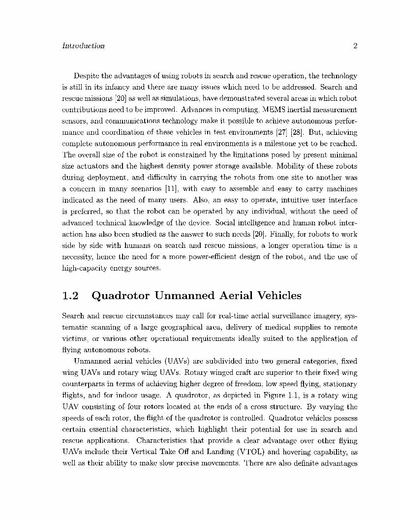
Unmanned aerial vehicles (UAVs) are subdivided into two general categories, fixed wing UAVs and rotary wing UAVs. Rotary winged craft are superior to their fixed wing counterparts in terms of achieving higher degree of freedom, low speed flying, stationary flights, and for indoor usage. A quadrotor, as depicted in Figure 1.1, is a rotary wing UAV consisting of four rotors located at the ends of a cross structure. By varying the speeds of each rotor, the flight of the quadrotor is controlled. Quadrotor vehicles possess certain essential characteristics, which highlight their potential for use in search and rescue applications. Characteristics that provide a clear advantage over other flying UAVs include their Vertical Take Off and Landing (VTOL) and hovering capability, as well as their ability to make slow precise movements. There are also definite advantages
Introduction 3
Figure 1.1: (Left) A model quadrotor and (right) the conceptual diagram
to having a four rotor based propulsion system, such as a higher payload capacity, and impressive maneuverability, particularly in traversing through an environment with many obstacles, or landing in small areas. Furthermore, a lot of research has already been conducted on the modeling and control of a quadrotor [1] [5] [9] [13] [25] [57].
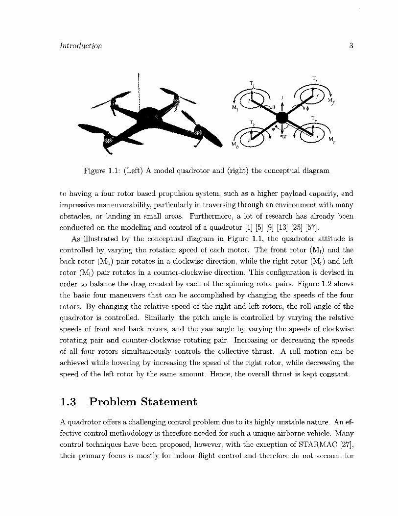
As illustrated by the conceptual diagram in Figure 1.1, the quadrotor attitude is controlled by varying the rotation speed of each motor. The front rotor (Mf) and the back rotor (Mb) pair rotates in a clockwise direction, while the right rotor (Mr) and left rotor (Mi) pair rotates in a counter-clockwise direction. This configuration is devised in order to balance the drag created by each of the spinning rotor pairs. Figure 1.2 shows the basic four maneuvers that can be accomplished by changing the speeds of the four rotors. By changing the relative speed of the right and left rotors, the roll angle of the quadrotor is controlled. Similarly, the pitch angle is controlled by varying the relative speeds of front and back rotors, and the yaw angle by varying the speeds of clockwise rotating pair and counter-clockwise rotating pair. Increasing or decreasing the speeds of all four rotors simultaneously controls the collective thrust. A roll motion can be achieved while hovering by increasing the speed of the right rotor, while decreasing the speed of the left rotor by the same amount. Hence, the overall thrust is kept constant.
1.3 Problem Statement
A quadrotor offers a challenging control problem due to its highly unstable nature. An ef-fective control methodology is therefore needed for such a unique airborne vehicle. Many control techniques have been proposed, however, with the exception of STARMAC [27], their primary focus is mostly for indoor flight control and therefore do not account for
Introduction 4
Figure 1.2: Quadrotor dynamics
environmental uncertainties. Another major drawback with the conventional quadrotor design is its high power
consumption, resulting in reduced flight times. Table 1.1 lists the flight times achieved by some key quadrotor projects. As the data shows, the maximum flight time obtained is roughly around 20 minutes. It is important to mention that most of the projects listed were not specifically aimed towards achieving higher flight times; however, considerations were taken into account in order to at least produce an acceptable flight time. As longer flight endurance is essential for accomplishing search and rescue missions, a quadrotor design capable of sustaining the power requirements for an extended time period is required.
With an aim to achieve autonomous flight, this thesis is focused on the design and development of a fuzzy logic based control strategy, specifically for dealing with nonlinear systems with environmental uncertainties. Also, this work is concerned with rectifying design disadvantages of quadrotors in order to improve the flight time.
The mass and power distributions of even the most integrated customized designs indicate bottleneck areas as shown in the Figure 1.3. It is evident that almost 60% of the system mass is comprised of the actuators and the battery. Also, a lion's share of 90% of the total power is consumed by the actuators only.
Therefore, in order to improve the flight time we need to find a solution for reducing

Introduction 5
Table 1.1: Quadrotor project flight times
Thesis/Project Flight-time Control Method Picture
STARMAC, Stanford University,
2005 [57] 10 min. Reinforcement
Learning
OS4, EPFL, December 2006 [6] 20 min. Backstepping
/ Pennsylvania State
University, Hanford, 2005 [26]
Est. 15 min. Actual 20 sec
PI v
Helio-copter, Brigham Young
University, Fowers, 2008 [21]
Est. 20 min. Visual feedback
HMX-4, Pennsylvania State University, 2002 [1]
3 min. Feedback Lin. SB Quad-Rotor UAV,
University of British Columbia
[13]
3 min. MBPC and Hoo i • Quad-Rotor Flying Robot, Universiti
Teknologi Malaysia [58]
5 min. PID

Introduction 6
Mass Distribution Power Distribution
Batte 44°/
Communications 2%
I k Sensors 5%
Controller 8%
Airframe 10%
Actuators 91%
Sensors 1 % Communications 3%
Controller 5%
Actuators 31%
Figure 1.3: Example mass and power distributions of a quadrotor.
the mass distribution for the battery and actuators, as well as minimizing the power consumption of the actuators.
Two fuzzy logic based flight controllers for an autonomous quadrotor are proposed. Im-plementation of the proposed control is carried out using Mamdani and Sugeno fuzzy inferencing methodologies. The advantage of the proposed methodology over other con-ventional methods is the ability to achieve stable flight control under disturbances that are common in outdoor environments. Also, the implementation is lighter in terms of computational loads.
In this study, the problem of having limited energy sources (batteries) on-board, and the higher consumption by the rotors, is dealt with by proposing innovative de-sign changes in the structure of the flying robot (quadrotor) and employing new power electronic technologies for aid.
The modified quadrotor model created is based on the older proposals of Heavy Lift Helicopters (HLH), a hybrid blimp-quadrotor configuration where the buoyant lift of the helium envelope takes care of the major dead weight of the design. The size and shape of the helium balloon is optimized in order to get the longest flight-time, while keeping the total size of the quadrotor, including the propellers, within 1.22 meter side to side.
A relatively newer concept of using a battery and super capacitor hybrid power source to increase the operational time, as well as to improve the battery life, is realized. This
1.4 Thesis Contributions

Introduction 7
proposed solution is implemented for the very first time on a quadrotor platform to the best of our knowledge. A simulation model of this battery and super capacitor hybrid power source, powering the four BLDC motors using PWM is also developed during the study.
By introducing these modifications to the existing designs of quadrotors a longer flight-time is accomplished, hence making these hybrid blimp-quadrotors a suitable choice for missions demanding higher flight endurance.
1.5 Thesis Organization
The first chapter of this thesis provides an introduction to the motivation behind the use of unmanned aerial vehicles in search and rescue missions. In particular, the idea of quadrotor as a potential search and rescue UAV is presented. The shortcomings with the quadrotor design are highlighted and proposal for improvements are provided.
Chapter 2 provides a comprehensive literature review regarding UAVs, highlighting the significance of quadrotors among UAVs. Relevant quadrotor design variations and characteristics are presented, with historical and current examples. In particular, the quadrotor flight control techniques are discussed and comparisons are drawn. Details about hybrid UAVs are cited and the use of supercapacitors in power related applications is discussed.
In chapter 3, the quadrotor's kinematics and dynamics are detailed, yielding the equations of motion. These equations are used as a guideline for developing the proposed intelligent flight control scheme.
In chapter 4, fuzzy logic is adopted for building the flight controller of the quadrotor. It has been witnessed that fuzzy logic control may offer several advantages over certain types of conventional control methods, specifically in dealing with highly nonlinear sys-tems and modeling uncertainties. Some of these advantages are explained and compared with other conventional control techniques. Two types of fuzzy inference engines are employed in the design of the flight controller each method of which is explained and evaluated.
Chapter 5 details the construction of the hybrid quadrotor UAV from scratch. The airframe construction, helium envelope design, and the system design are presented.
Chapter 6 is concerned with the development of the inertial measurement unit. An online attitude estimation technique is also presented and implemented. The GPS sensor and ultrasonic range finders are introduced.

Introduction 8
In chapter 7 the hybrid power supply unit design is elaborated. The use of superca-pacitors in power supplies is explored.
The experiments conducted throughout this research are summarized in chapter 8. Details of the quadrotor simulator and the real-world test-bed are presented, as well as the online attitude estimation results. Improvements in the overall flight-time are also shown through the experiments conducted on the hybrid UAV and the hybrid power supply unit.
Chapter 9 concludes the thesis by summarizing the achievements of this research work. Suggestions for future work are also detailed.
Chapter 2
Literature Review
This chapter provides a comprehensive background into previously published work rel-evant to the design aspects of the current project. The organization of the material presented herein follows a historical time-line, as it progresses from Unmanned Aerial Vehicles in general, to quadrotors in particular, with a focus on significant designs. A section is dedicated for detailing the concept of hybrid aerial vehicles and their proposed use in the field of UAVs. The last section covers the growing use of supercapacitors in the power electronics and their advantages in extending robots time of flight and improving the battery life.
2.1 Unmanned Aerial Vehicles
The UAV concept originated with the use of gyroscopes for the attitude stabilization of an aircraft [40]. As depicted in Figure 2.1, Lawrence Sperry successfully demonstrated the gyroscope-based stabilization of his plane in 1914, where disturbances were introduced by a man standing on the wing.
From the very first design in the early 1900s, known as the aerial torpedo, to the latest high-altitude, long-endurance military drones, such as the Global Hawk and Reaper [41], the use of unmanned aircraft for military purposes has become increasingly sophisticated and commonplace. Figure 2.2 shows current military UAVs and airspace classes.
At present, apart from military endeavours, UAVs are also being employed in various commercial and industrial applications. In particular, these include the use of unmanned helicopters for crop dusting or precision farming [52], and microwave autonomous copter systems for geological remote sensing [2]. STARMAC [57] is a multi-agent autonomous
9

Literature Review 28
Figure 2.1: 1914 test of seaplane's gyro-based stabilization [40]
60 000 ft MSl GsED
4§,§W:fW!SL. *ems (Cl-A)
18,000 ft MSL.
• mmt • Huttttr
mfmSom
Class G Airspace
t C I ~ E ) Class G •K*1«JM«0L
Figure 2.2: UAVs and airspace classes of the National Airspace System [41]
Literature Review 11
rotorcraft, that has potential in security-related tasks, such as remote inspections and surveillance. The commercially available quadrotor kit called DraganFlyer [29] has be-come a popular choice for aerial mapping and cinematography.
2.1.1 UAV Classification
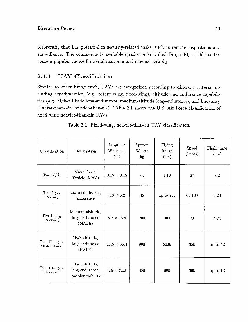
Similar to other flying craft, UAVs are categorized according to different criteria, in-cluding aerodynamics, (e.g. rotary-wing, fixed-wing), altitude and endurance capabili-ties (e.g. high-altitude long-endurance, medium-altitude long-endurance), and buoyancy (lighter-than-air, heavier-than-air). Table 2.1 shows the U.S. Air Force classification of fixed wing heavier-than-air UAVs.
Table 2.1: Fixed-wing, heavier-than-air UAV classification.
Classification Designation Length x Wingspan
(m)
Approx. Weight
(kg)
Flying Range (km)
Speed (knots)
Flight time (hrs)
Tier N /A Micro Aerial
Vehicle (MAV) 0.15 x 0.15 <5 1-10 27 <2
Tier I (e.g. Pioneer)
Low altitude, long endurance
4.3 x 5.2 45 up to 250 60-100 5-24
Tier II (e.g. Preda tor )
Medium altitude, long endurance
(MALE) 8.2 x 16.8 200 900 70 >24
Tier 11+ (e.g. Global Hawk)
High altitude, long endurance
(HALE) 13.5 x 35.4 900 5000 350 up to 42
Tier III- (e.g. Darks ta r )
High altitude, long endurance,
low-observability 4.6 x 21.0 450 800 300 up to 12

Literature Review 12
Rotary-wing micro aerial vehicles (MAVs) have not been officially classified. How-ever, generalized design guidelines are listed in Table 2.2 [44], based on performance requirements for a hypothetical urban mission.
Table 2.2: MAV guidelines
Specification Requirement Size <15 cm
Weight <100 g Range 1 to 10 km
Endurance 60 min Altitude <150 m
Speed 15 m/s Payload 20 g
Cost $1500
One successful fixed wing MAV design worth mentioning is the Black Widow [22], which is designed by AeroVironment Inc. Displayed in Figure 2.3, Black Widow is an 80 g MAV which can fly for 30 minutes at speed of 30 miles per hour and at maximum altitude of 250 m. Such a high flight endurance, relative to its miniature size makes Black Widow the best UAV designed, in terms of durability.
Figure 2.3: Black widow MAV [22]
Another very unique rotary wing MAV, named Mesicopter [33], was developed in Stanford University. Mesicopter, as presented in Figure 2.4, weighs a remarkable 3 g with a frame size of 1.5 cm square. The use of efficient miniature brushless DC motors, coupled with efficient power supply makes a flight time of 3 minutes possible. There are no on-board sensors, and therefore no control electronics present.

Literature Review 13
Figure 2.4: Mesicopter MAV
We note that as the dimensions (Reynolds number) decreases for a fixed wing craft its flight performance also decreases. However, flapping wing or rotary wing crafts can have relatively better flight performance while having low Reynolds numbers. This aspect shows the advantage of rotary wing UAVs over fixed wing UAVs. Figure 2.5 shows Reynolds number vs weight of various flying craft.
iflft Iflfc 104
10s, UgW Flaw
m Pistww § 10 # Sencter
MAV*
U J- 'V
103 10* 10s 1# 107 10® Reynolds Number
Figure 2.5: Reynolds number vs. gross weight [38]

Literature Review 14
2.2 Quadrotor History and Background
Louis Breguet and Jacques Breguet, two brothers working under the guidance of Professor Charles Richet, were the first to construct a quadrotor which they named Breguet Richet Gyroplane No. 1 [34]. The first flight demonstration of Gyroplane No. 1 with no control surfaces was achieved on 29 September 1907. Figure 2.6 shows the huge quadrotor with double layered propellers being prepared for its first manned flight.
Figure 2.6: Breguet Richet Gyroplane No. 1 [46]
Later, two additional designs were developed and experimental flights were conducted. The first, by Georges de Bothezat and Ivan Jerome in 1922, had six-bladed rotors placed at each end of an X-shaped truss structure, as shown in Figure 2.7.
Figure 2.7: Quadrotor designed by George De Bothezat, February 21, 1923 [46]
The second, shown in Figure 2.8, was built by Etienne (Ehmichen in 1924, and set distance records, including achieving the first kilometer long helicopter flight.

Literature Review 15
Figure 2.8: (Ehmichen quadrotor [46]
2.3 State of the Art
Since the inception of the quadrotor design, many quadrotor test-beds have been con-structed in different research projects, where simulators are also developed for testing the control laws beforehand. Mentioned here are some recent designs of note, with their specifications and capabilities.
2.3.1 Atilim University
In this research [32], LQR is used for attitude stabilization of a quadrotor model in Simulink and implemented using Simulink Real Time Windows Target utility interfaced to the setup by data acquisition cards. The commercially available Draganflyer Vti model is used as test-bed with off-the-shelf sensors. Six states are measured with the sensor set consisting of three ADXRS150 gyros, HMC2003 three axes magnetometer, and ADXL203 dual-axis accelerometer. The speed of Mabuchi DC motors is controlled by PWM signals generated by two PIC16F877 microcontrollers for switching the power transistors. Power is provided by off-board power supply and 12 V battery. The total system weighs 320 g without battery and is 300 mm side to side in dimensions without the 12 inch propellers.
For testing the system was suspended using a rope, as shown in Figure 2.9. Attitude stabilization was achieved at sub hovering levels but a poor performance was observed while hovering. The wiring and rope connected to the quadrotor created the main per-formance issue and resulted in disturbances during flight. The system suffered vibration issues due to the unbalanced propellers as well. The linearized approximations made in modeling the system also resulted in poor control performance.
Literature Review 16
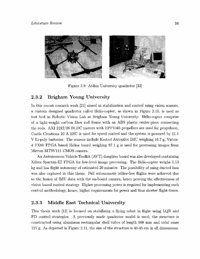
Figure 2.9: Atilim University quadrotor [32]
2.3.2 Brigham Young University
In this recent research work [21] aimed at stabilization and control using vision sensors, a custom designed quadrotor called Helio-copter, as shown in Figure 2.10, is used as test bed in Robotic Vision Lab at Brigham Young University. Helio-copter comprise of a light-weight carbon fiber rod frame with an ABS plastic center-piece connecting the rods. AXI 2212/26 BLDC motors with EPP1045 propellers are used for propulsion, Castle Creations 20 A ESC is used for speed control and the system is powered by 11.1 V Li-poly batteries. The sensors include Kestrel Autopilot IMU weighing 16.7 g, Virtex-4 FX60 FPGA based Helios board weighing 97.1 g is used for processing images from Micron MT9V111 CMOS camera.
An Autonomous Vehicle Toolkit (AVT) daughter board was also developed containing Xilinx Spartan-III FPGA for low-level image processing. The Helio-copter weighs 1.13 kg and has flight autonomy of estimated 20 minutes. The possibility of using ducted fans was also explored in this thesis. Full autonomous tether-free flights were achieved due to the fusion of IMU data with the on-board camera, hence proving the effectiveness of vision based control strategy. Higher processing power is required for implementing such control methodology, hence, higher requirements for power and thus shorter flight-times.
2.3.3 Middle East Technical University
This thesis work [12] is focused on stabilizing a flying robot in flight using LQR and PD control strategies. A previously made quadrotor model is used; the structure is constructed using aluminum rectangular shell tubes of length 500 mm and total mass 115 g. As depicted in Figure 2.11, the size of the structure is 40-45 cm in all dimensions.

Literature Review 17
I I
Figure 2.10: Brigham Young University quadrotor [21]
For propulsion, four Robby Power 280 DC motors are used with gearbox of ratio 4.8:1. Draganflyer Rotor Blades with length 314 mm were used with the motors. The inertial sensors consist of three gyros 241 Murata Env-05F03. Interfacing of the system with computer is done by using PIC based circuits and data acquisition circuits to computer running Matlab XPC target.
Due to the use of only gyroscopes for attitude estimation, the system suffers from the most common drift problem associated with the gyroscopes. As the drift was not modelled, therefore, the control performance was not satisfactory. Due to the use of brushed DC motors a higher power cost was also faced.
* ' C r
Figure 2.11: METU quadrotor [12]
2.3.4 Pennsylvania State University
This research work [26] is concerned with the development of a small semi-autonomous quadrotor using low cost MEMS sensors and microcontrollers. The system is controlled
Literature Review 18
by RF (Futaba model 6EXA) transmitter/receiver input and the motor speed control is done by implementing a pilot-in-loop PI control law on a PIC 18F8720 microcon-troller from Microchip. The angular velocity is measured by using MEMS gyroscopes (ADXRS150EB) and dual axis accelerometer (ADXL210EB) from Analog Devices.
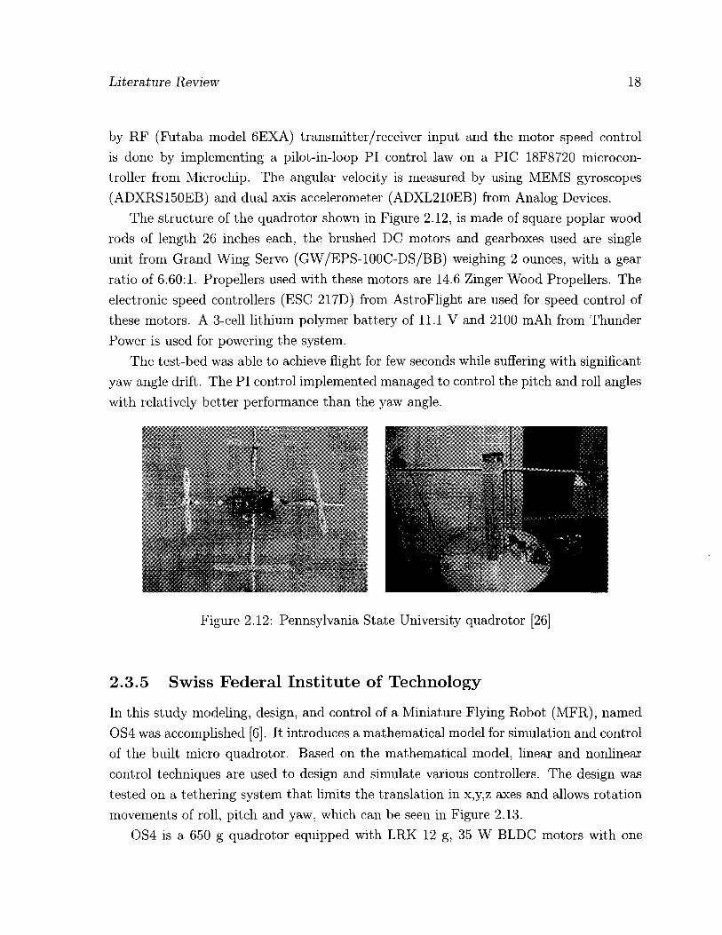
The structure of the quadrotor shown in Figure 2.12, is made of square poplar wood rods of length 26 inches each, the brushed DC motors and gearboxes used are single unit from Grand Wing Servo (GW/EPS-100C-DS/BB) weighing 2 ounces, with a gear ratio of 6.60:1. Propellers used with these motors are 14.6 Zinger Wood Propellers. The electronic speed controllers (ESC 217D) from AstroFlight are used for speed control of these motors. A 3-cell lithium polymer battery of 11.1 V and 2100 mAh from Thunder Power is used for powering the system.
The test-bed was able to achieve flight for few seconds while suffering with significant yaw angle drift. The PI control implemented managed to control the pitch and roll angles with relatively better performance than the yaw angle.
Figure 2.12: Pennsylvania State University quadrotor [26]
2.3.5 Swiss Federal Institute of Technology
In this study modeling, design, and control of a Miniature Flying Robot (MFR), named OS4 was accomplished [6]. It introduces a mathematical model for simulation and control of the built micro quadrotor. Based on the mathematical model, linear and nonlinear control techniques are used to design and simulate various controllers. The design was tested on a tethering system that limits the translation in x,y,z axes and allows rotation movements of roll, pitch and yaw, which can be seen in Figure 2.13.
OS4 is a 650 g quadrotor equipped with LRK 12 g, 35 W BLDC motors with one

Literature Review 19
stage gear box, powered by an 11 V, 3300 mAh battery weighing 230 g. On-board sensors are MT9-B IMU weighing 33 g, SRF10 from devantech weighing 3.5 g, and CCD camera for position sensing. The span of OS4 is 772 mm and the height is 200 mm.
A miniature computer module, based on s Geode 1200 processor running at 266 MHz with 128 MB of RAM and flash memory was developed. The computer module is x86 compatible and offers all standard PC interfaces. The whole computer is 44 g in mass, 56 mm by 71 mm in size and runs Linux. The controller includes an MCU for interfacing Bluetooth with the computer module. The same chip is used to decode the Pulse Position Modulation (PPM) signal picked up from a 1.6 g, 5 channel commercially available RC receiver. This decoding on our MCU makes it possible to interface the RC receiver to I2C bus and at the same time detect any anomaly in the channels. It is also possible to control the helicopter using a standard remote control.
OS4's position sensor is based on an on-board down-looking CCD camera and a sim-ple pattern on the ground. The camera provides a motion-blur free image of 320x240 at up to 25 fps. Several control techniques were implemented on the OS4 platform and out of these Backstepping Integral control performed quite satisfactorily and showed robust-ness during autonomous flights. This technique, however, requires higher computational power.
2.4 Flight Controller Designs for Quadrotors
In the past few years, a lot of research has already been conducted on the modeling and control of quadrotors. Lyapunov stability theory is used for stabilization and control of the quadrotor in [7] [16]. Conventional PD2 feedback and PID structures are used for
Figure 2.13: OS4 quadrotor [6]

Literature Review 20
simpler implementation of control laws, and comparison with LQR based optimal control theory is presented in [54] [8]. Backstepping control is also proposed with the drawback of higher computational loads in [25]. Visual feedback is used in many cases, using on-board or offboard cameras for pose estimation by [1] [24]. Fuzzy logic control techniques have also been proposed [14], along with neural networks [53] and reinforcement learn-ing [57]. Most of the control techniques mentioned above are primarily focused for indoor flight control and therefore do not account for environmental uncertainties and external disturbances.
2.5 Hybrid Aircraft/Unconventional UAV designs
The idea of combining the aerostatic lift of an airship with the aerodynamic lift of rotors, as in helicopters, gave birth to the concept of Hybrid Aircraft (HA). In HA, such as rotastat airships [31] or buoyant quadrotors, the significant lift is provided aerostatically by the airship or blimp portion to make it close to neutral buoyancy, intentionally keeping it slightly heavier than air. The design allows for a greater pay load capacity than an airship alone [3], with increased fuel efficiency over conventional aircraft, while possessing vertical takeoff and landing ability.
Figure 2.14 depicts one such early buoyant quadrotor design by Howe in 1975. Despite the concept of HA being around since the early 1900's, it is only recently that commercial HA designs have been proposed for heavy lift transportation applications [56]. A very recent study was conducted in development of a highly redundant hybrid UAV platform that was able to demonstrate precision hover and efficient translation for longer mission
x a z z r S i i l
Figure 2.14: Four rotor rotastat [31]

Literature Review 21
durations [17]. The SkyCat, shown in Figure 2.15, has a maximum payload of 1000 tons, with an endurance of up to 5 days.
2.6 Hybrid Power Sources
Significant amount of research has emerged in the last decade related to the use of supercapacitors in conjunction with batteries to improve the overall power density. Per-formance of the battery-supercapacitor hybrid power source was analyzed in [15], where the power source is connected to a pulsating load. Significant improvements in peak power up to five times, internal loss reduction of 74%, and battery run-times extension were noted. In another study [43], improving battery run-time for mobile application using supercapacitors was explored. Different techniques were presented to connect the battery and the supercapacitors using direct connection, a buck converter, and DC-DC converters. The results show a 4 — 12% increase in the run-time. Performance improve-ments were studied in [49], when a supercapacitor is used with a battery. The peak power is supplied by the supercapacitor and the energy is delivered by the battery, while suppressing transients and extending run-time.
2.7 Summary
A detailed background of UAVs and their classification, with a particular focus on the quadrotor UAV, was presented in this chapter. The details of several state of the art quadrotor designs, along with their advantages and drawbacks were discussed. Quadrotor flight control techniques published in the literature were presented and open research
Figure 2.15: The SkyCat hybrid aircraft [56]

Literature Review 22
areas explored. The concept of hybrid aircraft was presented and possibility of exploiting the advantages of an airship were discussed. Finally, the use of Supercapacitors to increase the power density of the batteries was elaborated.

Chapter 3
Quadrotor Kinematics and Dynamics
Mathematical modelling provides a description of the behaviour of a system. The flight behaviour of a quadrotor is determined by the speeds of each of the four motors, as they vary in concert, or in opposition with each other. Hence, based on its inputs, a mathematical representation of the system can be used to predict the position and orientation of the quadrotor. The same can further be used to develop a control strategy, whereby manipulating the speeds of individual motors results in achieving the desired motion.
To derive the full mathematical model of the quadrotor, we need to define its kinemat-ics and dynamics first. The kinematic equations provide a relation between the vehicle's position and velocity, whereas the dynamic model defines the relation governing the applied forces and the resulting accelerations.
This chapter starts by providing insight into the use of different reference frames and rotation matrices to define points of view. The first section defines the notation used throughout this text. Section 3.2 details the kinematics of the quadrotor and provides translational and rotational relationship equations. The quadrotor dynamic model is derived in Section 3.3, while Section 3.4 defines the forces and moments acting on the quadrotor. Finally the equations of motion are summarized.
23
Quadrotor Kinematics and Dynamics 24
3.1 Preliminaries
Before getting into the equations of kinematics and dynamics of the quadrotor, it is necessary to specify the adopted coordinate systems and frames of reference, as well as how transformations between the different coordinate systems are carried out.
The use of different coordinate frames helps identifying the location and attitude of the quadrotor in six degrees of freedom (6 DOF). For example, in order to evaluate the equations of motion, a coordinate frame attached to the quadrotor is used. However, the forces and moments acting on the quadrotor, along with the inertial measurement unit (IMU) sensor values, are evaluated with reference to the body frame. Finally, the position and speed of the quadrotor are evaluated using GPS measurements with respect to an inertial frame located at the base station.
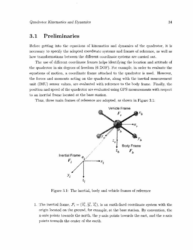
Thus, three main frames of reference are adopted, as shown in Figure 3.1:
Inertial Frame
Body Frame
Figure 3.1: The inertial, body and vehicle frames of reference
1. The inertial frame, T{ = (zt, yl, ), is an earth-fixed coordinate system with the origin located on the ground, for example, at the base station. By convention, the x-axis points towards the north, the y-axis points towards the east, and the z-axis points towards the center of the earth.

Quadrotor Kinematics and Dynamics 25
2. The body frame, Tb = {xl, yt, ~zt), with its origin located at the center of gravity (COG) of the quadrotor, and its axes aligned with the quadrotor structure such that the x-axis xl is along the arm with front motor, the y-axis yt is along the arm with right motor, and the z-axis z?, = xl x yt, where x denotes the cross product.
3. The vehicle frame, Tv = (xl, yt,, zt), is the inertial frame with the origin located at the COG of the quadrotor. The vehicle frame has two variations, T^ and Tq. J-q, is the vehicle frame, TV) rotated about its z-axis by an angle yj so that xl and yt are aligned with xl and yl, respectively. Tq is the T<p frame rotated about its y-axis, by a pitching angle, 6, such that and z j are aligned with xl and
respectively.
Translation and rotation matrices are used to transform from one coordinate reference frame into another desired frame of reference. For example, the transformation from Ti to T v provides the displacement vector from the origin of the inertial frame to the center of gravity (COG) of the quadrotor. Also, the transformation from Tv to JF6 is rotational in nature, thereby yielding the roll, pitch and yaw angles. The general notation is such that the rotation matrix R^? € K.3x3 maps a given frame J-\ to another frame T^-
The twelve state variables and corresponding notations defined below will be used throughout this text:
• Hi ~ \PX»Py' -PzVi
. hTFv = [0, e, v>k
• Prh = \Px,Py,-Pz]rb
. % = ft e,
3.2 Quadrotor Kinematics With the knowledge of the inertial frame position state variables PJR. and the body frame speed state variables PJRB, the translational motion relationship is derived as
Px Px T Px
Py = Py = Sir J V Py (3.1)
Fi . Pz . Fv . Pz . Fb
Quadrotor Kinematics and Dynamics 26
where •> V defined by
p3x3 is the rotation matrix that maps frame T\, to frame Tv and is
COCI/J s<ps9cip — ccpsip ccps9cip + scpsip T ^
R-pl — c9sip s<fis9sip + ccpcip ccps9sip — s(pcip —sQ s<pc9 ccpcd
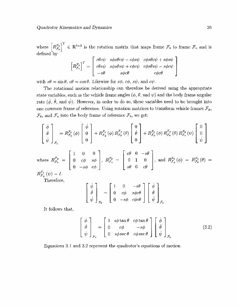
with sO — sinfl, c9 = cos 9. Likewise for scp, c<p, sip, and cip. The rotational motion relationship can therefore be derived using the appropriate
state variables, such as the vehicle frame angles (cp, 9, and ip) and the body frame angular rate (t/>, 9, and ip). However, in order to do so, these variables need to be brought into one common frame of reference. Using rotation matrices to transform vehicle frames J-^ Te, and Tv into the body frame of reference we get:
9 = R t \ (</>)
Tb
0 0 0
+ R p (0) (9) T,i 0 9 0
+ R% (0) {9) R% W 0 0
where R^? =
(VO = L
Therefore,
1 0 0
It follows that,
0 0 C(j> S(j)
— S(f) C(p R Te Tv
c9 0 -s9 0 c9
0 1 s9 0
" 0 " ' 1 0 -s9 ' ' 4> ' 9 = 0 c(f) scpc9 e
J . Th _ 0 —scp c(pc9 Tv
and I& (0) =
" 0 " 1 septan9 C(ptan9 4> 9 = 0 c(p —scp 9
A . Tv 0 s(f> sec 9 ccp sec 9 J . Tb
(3.2)
Equations 3.1 and 3.2 represent the quadrotor's equations of motion.
Quadrotor Kinematics and Dynamics 27
3.3 Quadrotor Dynamic Model
To build the dynamic model of the quadrotor we will use Newton-Euler formalism, while adopting the following assumptions:
1. The quadrotor structure is a rigid body.
2. The quadrotor frame is symmetrical.
3. The COG of the quadrotor coincides with the center of the rigid frame.
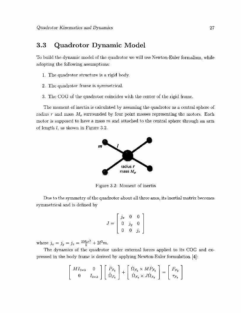
The moment of inertia is calculated by assuming the quadrotor as a central sphere of radius r and mass M0 surrounded by four point masses representing the motors. Each motor is supposed to have a mass m and attached to the central sphere through an arm of length I, as shown in Figure 3.2.
Figure 3.2: Moment of inertia
Due to the symmetry of the quadrotor about all three axes, its inertial matrix becomes symmetrical and is defined by
jx 0 0 J = 0 jy 0
0 0 jz
where jx = jy = jz = ^ + 2l2m. The dynamics of the quadrotor under external forces applied to its COG and ex-
pressed in the body frame is derived by applying Newton-Euler formulation [4]:
MI3x3 0 + " Ctjrb x MPrb ' ' Frb '
o / 3 X 3 _ +
_ x JttTh - T .

Quadrotor Kinematics and Dynamics 28
where M = M 0 +4m is the quadrotor's total mass, and F1 = [ f x fy fz] and rT = [r^ tq are the external force and torque vectors applied on the quadrotor's COG. The terms r^, TQ, and T^ are the roll, pitch and yaw torques respectively.
Thus, the translational dynamic model can be written as
Px i>Py -Opz ' 1
+ M
' f x '
Py = - Ippx 1
+ M fy . Pz . Tb _ Opx - 4>Py _ Tb h Tb
while the rotational model is
4>' 0 -6 ' ' <P ' t4> >
6 = J _ 1
-ip 0 J 9 + re 4> _ I 9 -4> 0 j, Tip
>
f jy~jz9ih 1 3x iTt> jz~jx (bib Jy r r +
Jy 3x7Jy <fi9
Tb
1 _ L TJ* -1
3.4 Aerodynamic Forces and Moments
With the derived kinematics and dynamics model, we will now define the forces and torques acting on the quadrotor. The forces include the aerodynamic lift generated by each rotor, and the gravitational pull acting in counter to the total lift generated. The moments are the torques generated in order to achieve the roll, pitch and yaw movements. The following forces and torques are produced:
Upward Force (Thrust): The total quadrotor thrust is the sum of thrust produced by each motor, as depicted in Figure 3.3:
T = Tf + Tr + Tb + Tt

Quadrotor Kinematics and Dynamics 29
PWM + APWM PWM + APWM
Figure 3.3: Quadrotor thrust
Rolling Torque: Rolling torque is produced by increasing the left rotor thrust while decreasing the right rotor thrust, or vice versa (Figure 3.4):
rt> = Z (T, - Tr)
Figure 3.4: Rolling torque
Pitching Torque: Pitching torque (Figure 3.5) is produced by increasing the front rotor thrust while decreasing the back rotor thrust, or vice versa:
re = I (Tf — Tb)

Quadrotor Kinematics and Dynamics 30
PWM PWM - APWM
Figure 3.5: Pitching torque
Yawing Torque: The yawing torque is the resultant of all four individual torques generated due to the spinning rotors. The front and back rotors spin in the clockwise direction, while the left and right rotors spin in the counterclockwise direction. As shown in Figure 3.6, an imbalance between these two pairs results in a yawing torque causing the quadrotor to rotate about its z-axis:
Ty, = Tf + Tb — T r — T\
Gravitational Force (Weight): Along with the other forces, the gravitational force acts on the COG of the quadrotor. In the vehicle frame this force is expressed as
=
0 0
Mg
with g being the gravitational constant. In the body frame the weight can be written as
0 ' —MgsO ' WV, = 0 = MgcOscf)
_Mg _ MgcOccf)

Quadrotor Kinematics and Dynamics 31
PWM - APWM PWM +APWM
Figure 3.6: Yawing torque
Including the forces and torques acting on the system, the equations of motion become as defined below.
Px IpPy -Opz ' " -gsd ' 0
Py = 4>Pz - Tp&x + gcdscp + 0
. Pz . rb _ Ofix - H>y . gcOccj) . M
' 4>' r jyTjz9ip i ' fjo> ' 6 =
jzT jx (bib Oy + j-re Jy
J . 3xT 3y<j>e 1 _ L TJ^ -1
3.5 Summary
This chapter presented the kinematics and dynamics of the quadrotor, whereby a de-tailed mathematical model of the system was derived. Three reference frames were also explained to define the points of view. The aerodynamic forces and moments acting on the quadrotor were defined and included in the derived model. Finally, the equations of motions were defined, to be used in devising a flight control strategy in the next chapter.

Chapter 4
Controller Design
This chapter details the development of a fuzzy logic flight controller for the quadrotor. The first section provides a generalized overview of fuzzy logic control and the advantages it offers for nonlinear control applications. Section 4.2 describes the control strategy for autonomous flight of the quadrotor. Based on the dynamics and kinematics derived in the previous chapter, a flight controller algorithm is thereby presented. Two inference engines are adopted for the fuzzy logic controller, which are the Mamdani and Takagi-Sugeno-Kang engines.
4.1 Fuzzy Logic Control
Since its inception in [59], fuzzy logic has been applied to various fields of engineering, manufacturing, business, and medicine, among others. Within the area of engineering, control systems offer significant applications for fuzzy logic, designated as fuzzy logic control. Before getting into details with regards to fuzzy logic control, we would first like to provide some basic facts about fuzzy systems and control. Although the term "fuzzy" would seem to imply something of an imprecise nature, however, here the term is used to define the phenomenon that fuzzy system theory characterizes. The control theory itself is very precise. Similarly, the fuzzy control is a special kind of nonlinear control, which is precisely defined.
Fuzzy logic control offers a great advantage over some conventional control methods which heavily depend on the exact mathematical model of the control system, specifically in dealing with nonlinear systems subjected to various types of environmental uncertain-ties. Being independent of the plant's parameters sets fuzzy controllers apart from the
32

Controller Design 33
conventional control schemes. Fuzzy controllers in general can be designed intuitively, in light of the knowledge acquired on the behavior of the system in hand. This knowledge is often gained through experience and common sense, regardless of the mathematical model of the dynamics governing this behavior. For example, in learning how to ride a bike, humans try build a set of common sense rules and learn from their failures, with-out paying any attention to the dynamic model of the bike. Fuzzy logic control tries to mimic this type of human-like reasoning and embrace it within a pre-defined math-ematical model to automate the control of complex systems characterized by ill-defined mathematical models, for example.
4.2 The Flight Controller Algorithm
The quadrotor is an under-actuated system with four actuators controlling its 6 degrees-of-freedom position/orientation. The flight controller is responsible for achieving two challenging goals simultaneously: (i) controlling the quadrotor's position, while (ii) sta-bilizing its attitude, i.e., orientation (roll, pitch and yaw angles). More specifically, given a desired position (px ,py ,pz) a n d yaw tp, the goal is to design a controller to force these control states to converge to their respective values, while maintaining the pitch and roll angles as close to zero as possible.
Let PWMm o l denote the PWM value of motor mot £ {f,r,b,l} for the front, right, back, and left motors, respectively. Then, the thrust and torque applied on the quadrotor by motor mot can be expressed as
Tmot
KT x PWMmot
T m o t = KtX PWMmot where KT and KT are motor-dependent parameters. This yields
" PWM f ' " T ' PWM r = G x
r4> PWMfe re
. PWM, . Ti>
with
Controller Design 34
- l KT KT KT KT
0 -I x KT 0 I x KT
I x KT 0 -I x KT 0 -KT KT -KT KT
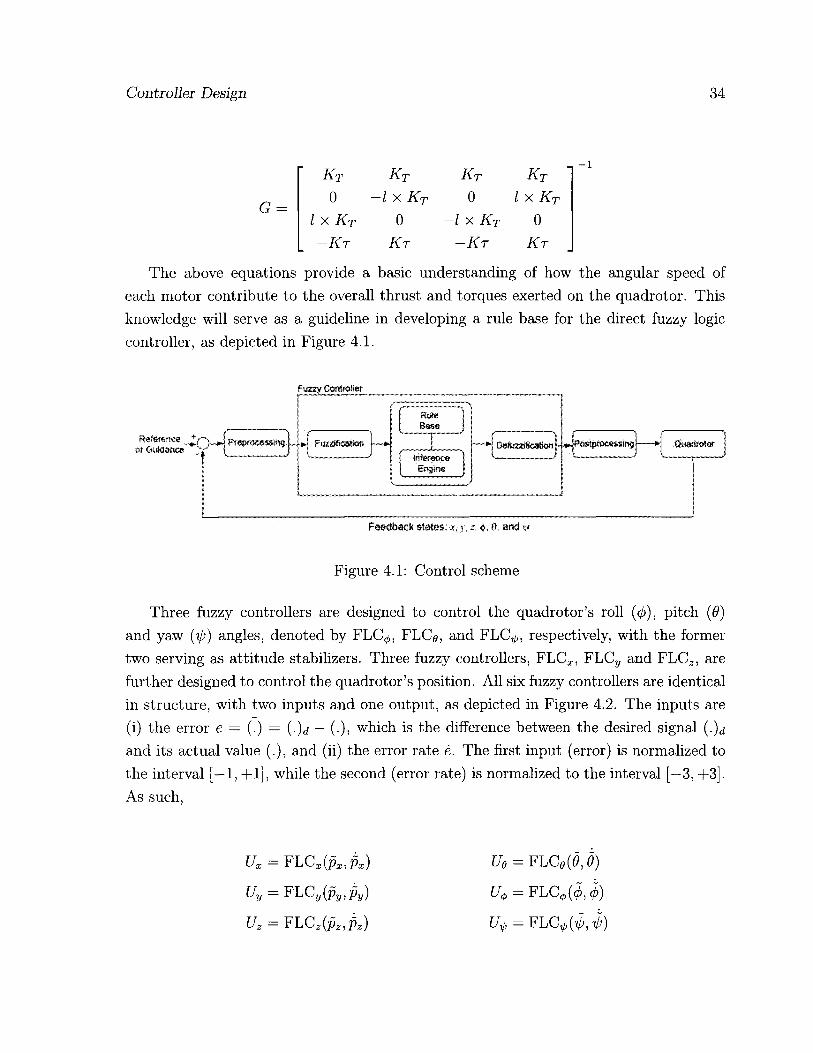
The above equations provide a basic understanding of how the angular speed of each motor contribute to the overall thrust and torques exerted on the quadrotor. This knowledge will serve as a guideline in developing a rule base for the direct fuzzy logic controller, as depicted in Figure 4.1.
fuzzy Controller
Feedback states: x, y,z. ft, arid v
Figure 4.1: Control scheme
Three fuzzy controllers are designed to control the quadrotor's roll (cp), pitch (9) and yaw (ip) angles, denoted by FLC^,, FLCg, and FLC^,, respectively, with the former two serving as attitude stabilizers. Three fuzzy controllers, FLCX, FLCy and FLCZ, are further designed to control the quadrotor's position. All six fuzzy controllers are identical in structure, with two inputs and one output, as depicted in Figure 4.2. The inputs are (i) the error e — (.) — (.)d — (.), which is the difference between the desired signal (.)<* and its actual value (.), and (ii) the error rate e. The first input (error) is normalized to the interval [—1, +1], while the second (error rate) is normalized to the interval [—3, +3]. As such,
Ux
Uy
u z
= F L C x ( p x , p x )
= FLCy{Py,Py)
= FLC z(pz ,pz)
Ue = FLCo{9,9)
U+ = FLC</,(0,4>)

Controller Design 35
Figure 4.2: System block diagram
In this control strategy, the desired pitch and roll angles, 9,j and (t),i, are not explicitly provided to the controller. Instead, they are continuously anticipated by controllers FLCX
FLCy in such a way that they stabilize the quadrotor's attitude. The input and output membership functions (Figure 4.3) of the FLC are tuned empirically and are defined by the following parameters:
iWjv(e) = trapezoid(—1, —0.15, 0)
I1p(e) — trapezoid(0, 0.15,1)
— triangle(—1.5, 0,1.5)
HN{U) = trapezoid(—1, —0.85, 0)
FJLP(U) = trapezoid(0, 0.85,1)
fiz(e) = triangle(-0.15,0,0.15)
/^v(e) = trapezoid(—3, —1.5, 0)
fip(e) = trapezoid(0,1.5, 3)
Hz(U) = triangle(—0.1, 0,0.1)
(a) Input variable error e. (b) Input variable error rate e. (c) Output variable U.
Figure 4.3: Input and output membership functions.
A unified rule base comprising nine IF-THEN rules is developed and is presented in

Controller Design 36
Table 4.1.
Table 4.1: The rule base of the fuzzy controller. e
N Z P N
e Z P
For it to be modular and independent of the quadrotor's parameters, the fuzzy logic controllers are bounded by pre-processing and post-processing blocks (Figure 4.1). The pre-processing module calculates the error e and error rate e and normalizes them ac-cordingly. The post-processing block uses the controllers output signals to calculate the PWM value of each motor as follows:
PWM f = Sat(Uz + UXe + Offset)
PWM r = SatiUz + Uy* + U* + Offset)
PWM6 = Sat(Uz - UXe - U^ + Offset)
PWM, = Sat{Uz - UY4, + + Offset)
where 'Offset' is a priori-defined bias to counter balance the weight of the quadrotor. The resultant PWM values are saturated to a maximum threshold which is a parameter of the motors used.
It is important to note that this control scheme does not depend on the kinematic and dynamic equations derived in previous chapter. Those equations are only used to build the quadrotors model in the simulator, which would be unnecessary with a real quadrotor test-bed. Being independent of the plant's parameters sets the fuzzy controllers apart from conventional control systems, which depend in one way or the other on the plant's mathematical model. The fuzzy controllers are designed in light of the knowledge acquired on the quadrotor's behavior and from its dynamic model. Therefore, changing the quadrotor or some of its physical parameters like the mass and inertia does not require redesigning the fuzzy logic controller. Instead, the post-processing module may need to be fine-tuned, to calibrate the offset for instance.
N N z N Z p Z P p
Controller Design 37
4.3 Fuzzy Inference System (FIS)
Two different fuzzy inference engines are implemented:
1. Mamdani fuzzy model [37]
2. Takagi-Sugeno-Kang (TSK) fuzzy model [51]
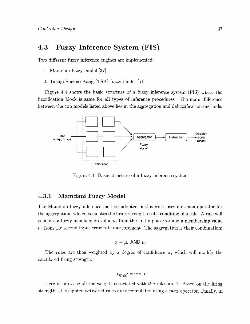
Figure 4.4 shows the basic structure of a fuzzy inference system (FIS) where the fuzzification block is same for all types of inference procedures. The main difference between the two models listed above lies in the aggregation and defuzzification methods.
Fuzzification
Figure 4.4: Basic structure of a fuzzy inference system
4.3.1 Mamdani Fuzzy Model
The Mamdani fuzzy inference method adopted in this work uses min-max operator for the aggregation, which calculates the firing strength a of a condition of a rule. A rule will generate a fuzzy membership value fiR from the first input error and a membership value fie. from the second input error rate measurement. The aggregation is their combination:
a = fie AND fie
The rules are then weighted by a degree of confidence w, which will modify the calculated firing strength:
amod = w * a
Here in our case all the weights associated with the rules are 1. Based on the firing strength, all weighted activated rules are accumulated using a max operator. Finally, in

Controller Design 38
this model the crisp output required by a controller is obtained through the centroid of area defuzzification method.
The surface plot shown in Figure 4.5 presents a graphical depiction of how the output changes as a function of error and error rate signals.
ErrorRate 1 Error
Figure 4.5: Mamdani surface plot
One known problem with this type of controller is the high computational burden associated to it, especially when implemented on an embedded system, as in our case.
4.3.2 Sugeno Fuzzy Model
To alleviate the problem of the high computational complexity of Mamdani FIS, a zero order TSK fuzzy inference engine is implemented. In this model, the output membership functions of the Mamdani fuzzy controller are replaced with fuzzy singletons N — — 1, Z = 0 and P = +1. The resultant surface diagram is given in Figures 4.6.
4.4 Summary
This chapter was concerned with the development of a fuzzy logic based flight controller,in order to control the position and orientation of a quadrotor. Fuzzy logic based control offers several advantages in nonlinear control applications. Here, the proposed controller design is independent of the quadrotor's parameters. Both the Sugeno and Mamdani
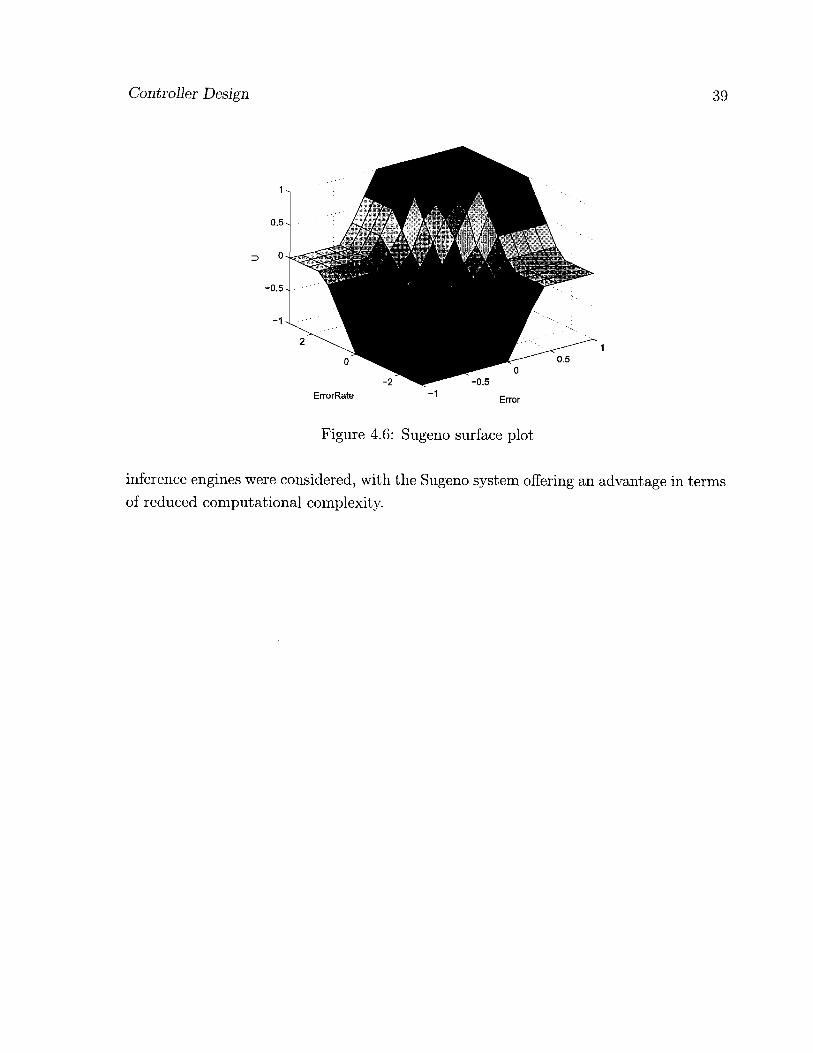
Controller Design 39
Figure 4.6: Sugeno surface plot
inference engines were considered, with the Sugeno system offering an advantage in terms of reduced computational complexity.

Chapter 5
Hybrid Quadrotor UAV Design
This chapter focuses on improving the inherent issues with the quadrotor UAV. The high power consumption of the quadrotor is one major factor causing reduced flight-times. To address this issue, an overall light-weight UAV design is realized, in addition a hybrid design is proposed for further reduction of the weight of the UAV. In the first section, the airframe design considerations are discussed. Also the selection process of the frame material and the construction details are explained. Expanding on the idea of a lighter design, the concept of hybrid quadrotor is presented in the following section. The advantage of lighter than air (LTA) aerostat are combined with the highly maneuverable craft such as the quadrotor. The selection process and design of the helium envelop is detailed. Also the calculations for the estimated buoyant lift generated are presented.
The third section explains the selection process of appropriate propulsion units for the quadrotor UAV. Motor and propeller selection based on optimal thrust to power ratio is presented.
The last section elaborates on the total system design, explaining the sensor input-output requirements and selection of the most appropriate computational platform. The chosen Axon board is presented and its features are explained. Also the algorithm of the fuzzy flight control application is detailed.
5.1 Airframe Design
The airframe or the mechanical structure of an aerial vehicle plays a significant role in affecting the overall performance and the stability of the craft. Quadrotors, when compared with other aerial crafts, are unique in their nature to possess a simplistic
40

Hybrid Quadrotor UAV Design 41
design of the airframe. The design of the airframe is a simple cross structure in one plane as depicted in Figure 5.1. The fundamental requirements are that the airframe is rigid and symmetrical, with its COG located at the center of the cross structure. Another mandatory requirement for the airframe is to be ultra light-weight.
Different kinds of materials having characteristics suitable to the type of aircraft are used for the airframe construction. Aluminium and its alloys are extensively used in aerospace industry due to their high strength-to-weight ratio. Carbon fiber reinforced polymer (CFRP) is another favoured choice, proving the same strength-to-weight ratio as aluminium or steel but weighs significantly less then the counterparts. For the quadrotor airframe three materials, aluminium, CFRP, and poplar wood, were considered. Each offers different strength-to-weight ratio and weighs different, as listed in Table 5.1. Car-bon fiber is chosen for the airframe due to its high strength-to-weight ratio, which is suitable for the desired design.
The desired airframe consists of four CFRP cylindrical rods of length 0.61 m. The inner diameter is 3.1 mm and the outer diameter is 5mm providing desired stiffness. For joining the CFRP rods at the center a plastic rectangle of size 5x5x1.6 cm is machined to provide the through holes for perfect fitting of the rods. Set-screws were used to further hold the rods from any slippage or rotation. To provide extra support for the rods to reduce any chances of vibrations, different options were considered. In some designs (as in draganflyer, STARMAC), additional CFRP rods were used to join the ends of the rods. However, this increases the weight of the vehicle. A different approach was adopted here by using non-stretchable nylon cord to join the ends of the four rods. A significant reduction in vibrations was noted as a result. The designed airframe weighs only 110 g
Figure 5.1: Quadrotor airframe CAD diagram.
Hybrid Quadrotor UAV Design 42
Table 5.1: Airframe material comparison.
Material Strength Weight Dimensions Picture
Aluminum High 113 g 13x13x610
' I.
Poplar Wood Medium 45 g 10x10x760
Carbon Fiber High 12 g 5x610
— a -
and is rigid enough for the desired application.
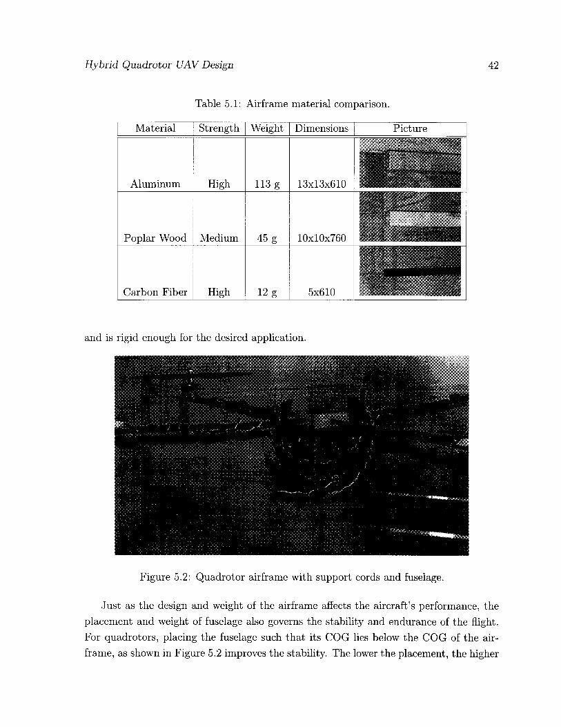
Figure 5.2: Quadrotor airframe with support cords and fuselage.
Just as the design and weight of the airframe affects the aircraft's performance, the placement and weight of fuselage also governs the stability and endurance of the flight. For quadrotors, placing the fuselage such that its COG lies below the COG of the air-frame, as shown in Figure 5.2 improves the stability. The lower the placement, the higher

Hybrid Quadrotor UAV Design 43
the overall flight stability of the quadrotor.
5.2 Helium Envelope Design
When designing an aircraft, a lot of consideration is given to the overall weight and aerodynamics of the craft to maximize the lift and minimize drag. In quadrotor the aerodynamic lift is generated by the total contribution of four rotor's individual thrust. This lift is responsible for balancing the weight of the whole vehicle, also in gaining altitude the lift is greater than the weight.
The weight of the quadrotor is one of the most important factor and in this research special attention is given for optimizing this aspect. In ideal conditions, a flying battery would result in 100% battery mass contribution to the total mass. Similarly, a motor without any mass are a dream come true for any aeronautical engineer, resulting in a zero percent motor mass contribution to the total mass. These conditions are unrealistic in their nature. However, the proposed innovative design of hybrid blimp-quadrotor offers to achieve these goals.
In an airship or blimp, the buoyancy lift generated by the helium filled balloon is used for ascending in altitude. This buoyancy lift, balance and overcomes the total weight of the vehicle to achieve hovering and climbing maneuvers. This characteristic feature of airships when combined with the versatile maneuvering capabilities of quadrotor results in a high endurance UAV, called here a hybrid blimp-quadrotor.
The design and development of the helium balloon involved first the selection of the most appropriate material for the envelop and then focused on the shape and construction of the envelope to satisfy the aerodynamics while adding the aerostatic ability.
Many kinds of materials are used for containing the helium gas offering different permeability at different thickness of the material used. Helium with molecular weight 4 gram/mole, is a lot lighter than the average air mixture weighing 28.8 gram/mole. However, this smaller atomic size also makes it difficult to contain helium, therefore specialized materials such as latex coated with a liquid plastic called high float, biaxially-oriented polyethylene terephthalate (boPET) polyester film, mostly known as Mylar, and polyurethane. Polyurethane is a very durable and tough material offering high tensile strength ranging from 4000 to 9500 psi, and is most suitable for retaining helium. Its desirable qualities such as ability to withstand 800 percent elongation before breaking, flexibility at temperatures as low as —60°F, high abrasion and puncture resistance, makes it ideal for use in demanding environments.

Hybrid Quadrotor UAV Design
Table 5.2: Helium envelope material comparison, VG=Very Good, P=Poor.
44
Material Retention Elasticity Welding Weight Cost PolyUrethane VG Best VG Very light Expensive PolyEthylene P Low Bad Slight heavy Dirt cheap
PolyPropylene VG Good VG Slight heavy Cheap PolyVinylChloride VG P Best Heavy Slight expensive
Nylon VG VG VG Light Slight expensive Mylar VG None VG Lightest Slight expensive
The shape of the helium envelope also determines the buoyancy lift generated. A spherical shape balloon having lower surface-area-to-volume ratio provides higher buoy-ancy lift than the same volume ellipsoid with larger surface-area-to-volume ratio. How-ever when compared to spherical balloons, the ellipsoid shaped balloons offer higher flight stability and less drag from the winds.
The resulting helium envelopes as shown in Figure 5.3, are ellipsoids made of polyurethane material of thickness 4 mil and 2 mil weighing 183 g and 100 g respectively. The con-struction was done by first cutting two circles of radius 0.46 m, the two pieces are placed together with centers coinciding. The outer edge of about 4 cm was marked for the seam, and the inner circle is covered with a heavy sheet leaving the outer edge exposed. The outer edge is then heated according to manufacturers specifications, using a hot-air gun to fuse the two sheets together. The completed balloon is then reversed to bring the seams inside the balloon.
Figure 5.3: The helium envelopes, (a) 4mil thickness balloon; (b) 2mil thickness balloon.

Hybrid Quadrotor UAV Design 45
The balloon dimensions are 0.46 m in radius, with 0.37 m in height. It can hold up to 0.15 cubic-meters of helium. The buoyancy generated by 0.17 cubic-meter of pure helium is estimated to be 200 g. Enough to balance its own weight of 100 g and provide buoyancy to counter 100 g of the quadrotor's weight.
Table 5.3: Buoyancy lift vs. envelope volume.
Mass (g) Volume (m3) Radius (m) Height (m) 100 0.07 0.36 0.29 125 0.11 0.42 0.34 200 0.17 0.49 0.39 300 0.25 0.55 0.44 400 0.34 0.61 0.49
5.3 Propulsion Unit
The propulsion unit comprises four Brushless DC (BLDC) motors, matching Electronic Speed Controllers (ESCs) and four propellers. The BLDC motors are gaining popularity due to their advantages over the traditional brushed DC motors. For low-torque applica-tions BLDC motors provide better speed versus torque characteristics. In addition, the torque-to-size ratio is higher making them useful for UAV applications where size and weight matters. Also, higher efficiency, long operational life and faster speeds combined with noiseless operation make BLDC motors a preferred choice. The propulsion unit is tested for its flight efficiency and tuned for the quadrotor UAV.
5.3.1 Brushless D C Motors
The BLDC motor selected for the quadrotor UAV is Great Planes RimFire 28-26-1000. The eight digit numbering system provides the basic specifications about the motor. The last four digits are the Kv (RPM/Volt) ratings of the motor. Motors with lower Kv rating have higher number of winding turns and spins slower and can spin a larger propeller consuming less current. Similarly, motors with higher Kv rating have low number of winding turns and spin faster with a small propeller but consumes higher current. These characteristics emphasize for prior analysis on the type of application. In our case, the quadrotor has four motors and it is mandatory to select motors with lower Kv rating to conserve maximum power.

Hybrid Quadrotor UAV Design 46
GIWMSM-28-28-130® kV GPHS4S3S • J8 -26- t«» k¥
Figure 5.4: The Rimfire 28-26-1000 BLDC motor.
Rimfire 28-26-1000 motor, as shown in Figure 5.4, weighs 41 g, requires input voltage of 7.4 V to 11.1 V, and have 0.7 A no-load current. The maximum limit on the current is 12 A to 15 A where 15 A is the surge current. The motor can handle a slow flyer propeller size ranging between 9x3.5 (length x pitch) to 11x4.7 inches.
5.3.2 Electronic Speed Controller (ESC)
BLDC motors are a kind of synchronous motors and requires a timed sequence of commu-tation for their operation. This commutation is provided by a microcontroller switching the MOSFETs based on the feedback from the Hall sensors built-in the motors. The microcontroller and the power commutation circuit are combined to form an Electronic Speed Controller (ESC). The input to this ESC is usually a PWM signal sent from the high-level controller to set the desired speed of the motor. An ESC helps to free the main high-level controller for unnecessary performance burden.
The ESC selected for matching the BLDC motor specifications is ElectriFly Silver Series 12 A, shown in Figure 5.5. It weighs 14 g and can deliver current from 12 A to a maximum surge limit of 15 A. The input power requirements are 2-4 cells LiPo battery with voltage up to 20 V. The ESC operates at a fixed frequency of 8.5 KHz and is programmed for safety start of the motors.
Figure 5.5: Diagram of ESC inputs and outputs.

Hybrid Quadrotor UAV Design 47
«1 .Qms | , JjjfYis
lull left
2 . 0 m s — < - full right
— 20ms (1 frame)
Start of Frame
Figure 5.6: The PWM timing diagram.
The ElecriFly S12 ESC requires a standard input PWM signal as shown in Figure 5.6, of period 20 ms with a duty cycle varying from 1 ms to 2 ms, used mostly in RF transmitters for servo motor control. The safe start prevents the motor from rotating when the battery is first connected. An arming routine of specific signals is required every time the battery is connected, to arm the motor for functioning.
5.3.3 Propellers
A quadrotor requires two sets of counter propeller pairs for balancing its aerodynamics. Various size propellers are available in different materials, however, finding matching pair of counter propellers is a difficult task and not many types are easily available unless manufactured in-house. In this research, three different types of propellers as shown in Table 5.4, were tested to observe the effects of propeller stiffness on the power consumed and thrust generated. Propellers made with light weight maple wood, fiberglass-nylon composite, and simple plastic, were used in the experiments.
The selection of the most efficient propeller requires finding out the propeller with the highest thrust to current ratio. For observing the thrust to current ratio an experimental setup was arranged. The propulsion unit was mounted on a wooden platform placed on a table top weight measure as shown in Figure 5.7. The system is supplied 11.1 V with maximum current limit of 12 A from a power supply. The motor is controlled using a PIC16F917 microcontroller board producing PWM values for the ElectriFly ESC. The PWM value increases with the press of a button on the microcontroller kit. This
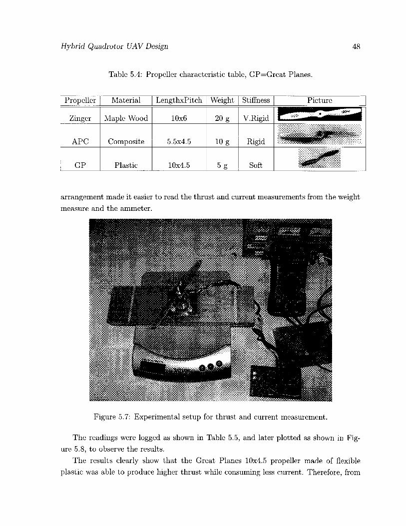
Hybrid Quadrotor UAV Design
Table 5.4: Propeller characteristic table, GP=Great Planes.
48
Propeller Material LengthxPitch Weight Stiffness Picture
Zinger Maple Wood 10x6 20 g V. Rigid
APC Composite 5.5x4.5 10 g Rigid
GP Plastic 10x4.5 5 g Soft
arrangement made it easier to read the thrust and current measurements from the weight measure and the ammeter.
Figure 5.7: Experimental setup for thrust and current measurement.
The readings were logged as shown in Table 5.5, and later plotted as shown in Fig-ure 5.8, to observe the results.
The results clearly show that the Great Planes 10x4.5 propeller made of flexible plastic was able to produce higher thrust while consuming less current. Therefore, from
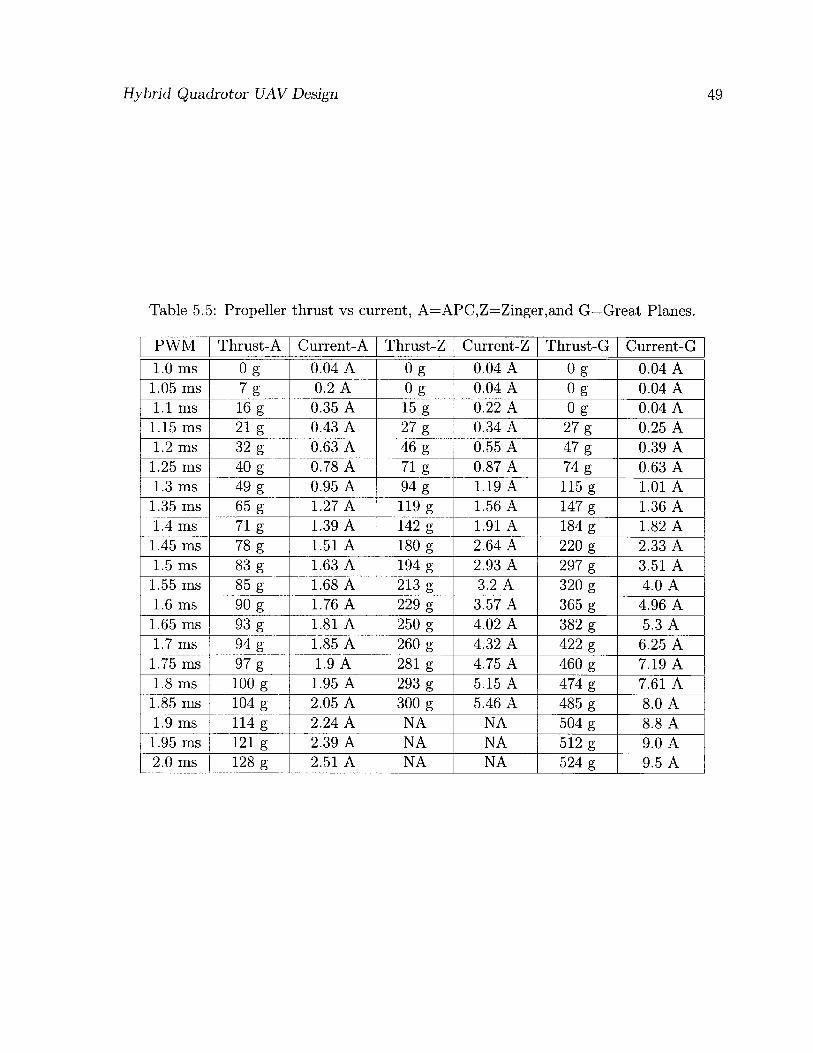
Hybrid Quadrotor UAV Design 49
Table 5.5: Propeller thrust vs current, A=APC,Z=Zinger,and G=Great Planes.
PWM Thrust-A Current-A Thrust-Z Current-Z Thrust-G Current-G 1.0 ms 0 g 0.04 A 0 g 0.04 A Og 0.04 A
1.05 ms 7 g 0.2 A Og 0.04 A 0 g 0.04 A 1.1 ms 16 g 0.35 A 15 g 0.22 A Og 0.04 A
1.15 ms 21 g 0.43 A 27 g 0.34 A 27 g 0.25 A 1.2 ms 32 g 0.63 A 46 g 0.55 A 47 g 0.39 A
1.25 ms 40 g 0.78 A 71 g 0.87 A 74 g 0.63 A 1.3 ms 49 g 0.95 A 94 g 1.19 A 115 g 1.01 A
1.35 ms 65 g 1.27 A 119 g 1.56 A 147 g 1.36 A 1.4 ms 71 g 1.39 A 142 g 1.91 A 184 g 1.82 A
1.45 ms 78 g 1.51 A 180 g 2.64 A 220 g 2.33 A 1.5 ms 83 g 1.63 A 194 g 2.93 A 297 g 3.51 A
1.55 ms 85 g 1.68 A 213 g 3.2 A 320 g 4.0 A 1.6 ms 90 g 1.76 A 229 g 3.57 A 365 g 4.96 A
1.65 ms 93 g 1.81 A 250 g 4.02 A 382 g 5.3 A 1.7 ms 94 g 1.85 A 260 g 4.32 A 422 g 6.25 A
1.75 ms 97 g 1.9 A 281 g 4.75 A 460 g 7.19 A 1.8 ms 100 g 1.95 A 293 g 5.15 A 474 g 7.61 A
1.85 ms 104 g 2.05 A 300 g 5.46 A 485 g 8.0 A 1.9 ms 114 g 2.24 A NA NA 504 g 8.8 A
1.95 ms 121 g 2.39 A NA NA 512 g 9.0 A 2.0 ms 128 g 2.51 A NA NA 524 g 9.5 A

Hybrid Quadrotor UAV Design 50
Current (A)
(a)
Current (A)
(b)
Current (A)
Figure 5.8: Thrust to current plots: (a) APC propeller; (b) Zinger propeller; (c) Great Planes propeller.

Hybrid Quadrotor UAV Design 51
a power conservation point of view selecting the Great Planes propellers was certain when compared with the ideally rigid Zinger propeller. Being flexible, this propeller is prone to the most common issue of blade flapping that causes nonlinearities in the thrust produced. This drawback is considered and accepted in the light of the fuzzy controllers capability to overcome model uncertainties and nonlinearities.
5.4 System Design and On-board Controller
For implementing the designed fuzzy flight controller a computational platform is re-quired, which can take multiple inputs from the sensors and the user, perform all the necessary computations, and control the motors for desired flight maneuver. Some of the necessary requirements are:
• Light-weight
• Small size
• Sufficient I /O and memory
• Meets computational load
• Power efficient
• Easily reprogrammable
• Supports open source coding
The system design is elaborated in the Figure 5.9. Few options were considered after surveying through most of the popular microcontroller platforms, detailed in Table 5.6. Society of Robots (SoR), Axon microcontroller as shown in Figure 5.10, was designed specifically for robotic applications and is one of the most compact and light-weight microcontroller board. Apart from these physical aspects, Axon offers several features as mentioned in the Table 5.6, which clearly sets it apart from most of the microcontroller boards available in the market.
The processing is accomplished with the on-board ATmega640 microcontroller run-ning at 16 MHz. The inertial measurement unit data is sampled using a built-in 10-bit analog to digital converter. The over-all system component summary is given in Ta-ble 5.7.

Hybrid Quadrotor UAV Design 70
•W. "3T •ii
A X O N
TAV! r.VM: rWWt ."VMU4
fcLfct. rn*l,Y SVfcN StHtS r AESt, tu <u m -u i l 1! i i i vi w w f
*lM(-,Kk 2K.?6.1vUi'Hlt>. MUf-JN
A A
Figure 5.9: System block diagram for the flight controller.
Table 5.6: Microcontrollers comparison table.
Feature Axon Arduino PIC24FJ256 PIC32MX460 Speed 16MHz-8bit 20MHz-8bit 8MHz-16bit 8MHz-32bit Flash 64kb 16kb 256kb 512kb RAM 8kb lkb 16kb 32kb ADC 16 6 16 16 PWM 9Ch 6Ch 9Ch 5Ch Timers 6 3 5 6 UART 4 1 4 2 USB Yes Yes Yes Yes SPI Yes No Yes Yes I2C Yes No Yes Yes I /O 55 17 52 85 SBC Yes Yes BreakoutBrd BreakoutBrd
PowerBus Yes No No No Cost $100 $35 $20 $40

Hybrid Quadrotor UAV Design 53
Figure 5.10: Society of robots, Axon board.
Table 5.7: The quadrotor UAV component summary.
Component Specifications Weight (g) 4 Carbon fiber rods Frame arms of 0.61 m length 52
Center piece Frame center joint 58 4 Motor mounts Aircraft grade aluminum sheets 40
4 Brushless DC motors RIMFIRE 1000 kV, 135Watts 164 4 Electronic Speed Controllers ElectriFly 12 A ESC 150 Watts 56
4 Composite propellers Counter rotating sets L=10", P=4.5" 24 4 Propeller adapters Collet type aluminum 3-5 mm 20
Lithium polymer battery 11.1 V 2100 mAh 215 Power supply board Hybrid PSU 70 IMU sensor board ADXL330, IDG300, ADXRS300 44
GPS Pharos iGPS-500 33 Bluetooth MCB3100 13
Axon board ATmega640 34 Standoffs and screws Aluminum frame assembly 53
Casing Plastic frame assembly 97 Helium Envelope 2 mil polyurethane 100
Total Weight 1073
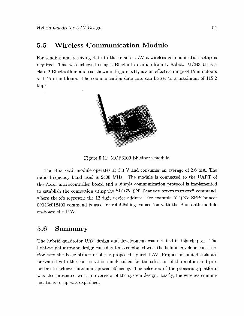
Hybrid Quadrotor UAV Design 54
5.5 Wireless Communication Module
For sending and receiving data to the remote UAV a wireless communication setup is required. This was achieved using a Bluetooth module from DrRobot. MCB3100 is a class-2 Bluetooth module as shown in Figure 5.11, has an effective range of 15 m indoors and 45 m outdoors. The communication data rate can be set to a maximum of 115.2 kbps.
Figure 5.11: MCB3100 Bluetooth module.
The Bluetooth module operates at 3.3 V and consumes an average of 2.6 mA. The radio frequency band used is 2400 MHz. The module is connected to the UART of the Axon microcontroller board and a simple communication protocol is implemented to establish the connection using the "AT+ZV SPP Connect xxxxxxxxxxxx" command, where the x's represent the 12 digit device address. For example AT+ZV SPPConnect 00043e018400 command is used for establishing connection with the Bluetooth module on-board the UAV.
5.6 Summary
The hybrid quadrotor UAV design and development was detailed in this chapter. The light-weight airframe design considerations combined with the helium envelope construc-tion sets the basic structure of the proposed hybrid UAV. Propulsion unit details are presented with the considerations undertaken for the selection of the motors and pro-pellers to achieve maximum power efficiency. The selection of the processing platform was also presented with an overview of the system design. Lastly, the wireless commu-nications setup was explained.

Chapter 6
Sensing and Perception
For making an autonomous flight possible it is important to have information about the attitude of the UAV and its position coordinates in space. Furthermore, to prevent the UAV from colliding into obstacles, an obstacle detection technique is also required. The attitude of the UAV is determined using a customized inertial measurement unit developed in-house. Position measurements are obtained from a global positioning system (GPS), in the form of latitude, longitude and altitude coordinates . Ultrasonic ranging sensors are employed for obstacle detection and avoidance.
This chapter details the selection of suitable sensors required for the autonomous flight of the quadrotor. The design and construction of the inertial measurement unit is provided in the first section and the adopted online attitude estimation methodology is explained in the second section of the chapter. A comparison of attitude estimation techniques is also provided. The third and fourth sections explain the GPS and ultrasonic sensors used.
6.1 Inertial Measurement Unit Design
The inertial measurement unit comprises triple axis gyroscope for measuring the rota-tional rates and triple axis accelerometer for measuring the gravitational forces acting on the UAV. Two rate gyros are used for creating a full triple axis rotational acceleration measurement system.
The first gyro is a dual-axis IDG-300 break-out board made by InvenSense, used for measuring the roll and pitch rotational rates. The IDG-300 as shown in Figure 6.1, consists of two independent MEMS gyroscopes with a full scale range of ±500° jsec.
55

Sensing and Perception 56
The output of both gyroscopes is low-pass filtered to eliminate noise. However, exter-nal low-pass filters are also recommended for attenuating the high-frequency noise with frequencies higher than 10 kHz. The bandwidth of the sensor was factory calibrated at 140 Hz, which was further reduced using external low-pass filter to 10 Hz, which is the desired frequency of the IMU. The sensor operates at a voltage of 3.3 V and consumes 9.5 mA current.
Figure 6.1: InvenSense IDG-300 dual-axis gyroscope
The yaw rotational rate is measured using Analog Devices ADXRS300EB evaluation board as shown in the Figure 6.2. Operating at a voltage of 5.0 V and supply current of 6.0 mA, ADXRS300EB provides a full scale range of ±300°/sec. The factory set bandwidth of 40 Hz is reduced to 10 Hz for improving the noise floor by using an external low-pass filter with appropriate RC constants. This evaluation board also provides a temperature sensor output for calibrating the measurements with respect to temperature changes.
Figure 6.2: Analog Devices ADXRS300EB yaw-rate gyroscope
The three-axis accelerometer ADXL330Z, is used for measuring linear accelerations. Figure 6.3 shows the sensor's evaluation board with a measurement range of ±3<7 min-imum. The sensor operates at a voltage of 3.3 V and consumes 320 FJ,A current. The
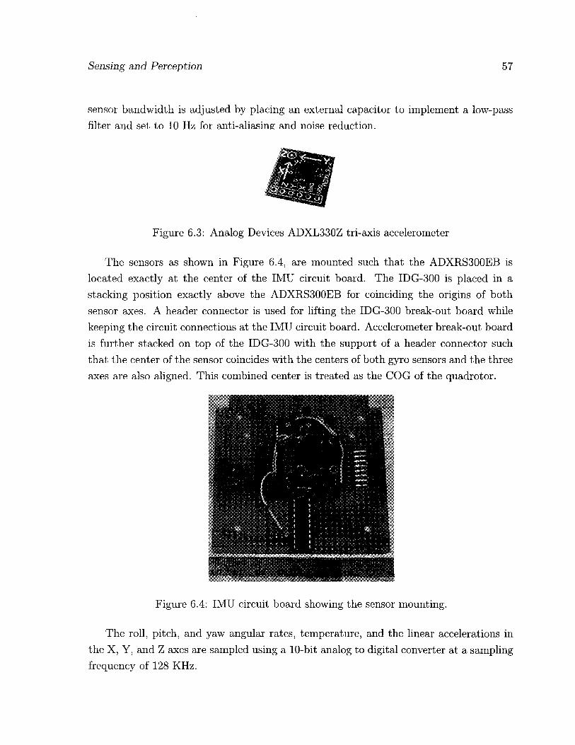
Sensing and Perception 57
sensor bandwidth is adjusted by placing an external capacitor to implement a low-pass filter and set to 10 Hz for anti-aliasine and noise reduction.
Figure 6.3: Analog Devices ADXL330Z tri-axis accelerometer
The sensors as shown in Figure 6.4, are mounted such that the ADXRS300EB is located exactly at the center of the IMU circuit board. The IDG-300 is placed in a stacking position exactly above the ADXRS300EB for coinciding the origins of both sensor axes. A header connector is used for lifting the IDG-300 break-out board while keeping the circuit connections at the IMU circuit board. Accelerometer break-out board is further stacked on top of the IDG-300 with the support of a header connector such that the center of the sensor coincides with the centers of both gyro sensors and the three axes are also aligned. This combined center is treated as the COG of the quadrotor.
Figure 6.4: IMU circuit board showing the sensor mounting.
The roll, pitch, and yaw angular rates, temperature, and the linear accelerations in the X, Y, and Z axes are sampled using a 10-bit analog to digital converter at a sampling frequency of 128 KHz.

Sensing and Perception 58
6.2 Online Attitude Estimation Technique
Attitude control is an essential capability required for any autonomous vehicle. Almost all autonomous vehicle control algorithms are dependent on good attitude estimation. Both in terrestrial and particularly in aerial vehicles the attitude estimate is the main feedback to the controller. Inertial sensors such as gyroscopes and accelerometers are very common in applications requiring attitude estimation. Microelectromechanical systems (MEMS) based inertial sensors have gained significant popularity in the past few years mainly due to their miniature profile and cost effectiveness. However, MEMS inertial sensors have their own drawbacks, such as noisy measurements and sensitivity to electromagnetic noise. Therefore, the use of such devices in attitude control applications requires serious considerations in terms of developing schemes for improving the measurements, as well as attenuating the noise.
Rate gyros are used for measuring angular rates and usually provide relatively good precision measurements with low noise. Integrating the measurements over time provides an estimate of the angular displacement. Hence, the angular orientation can be deter-mined if the initial position is known and the sensor has zero mean noise. In reality, the zero mean noise expectation from MEMS sensors is not realistic, therefore, a drifting DC value refered to as "drift" occurs. The integration of measurements with drift results in a growing error on the angle estimates, as depicted in Figure 6.5.
A weaker alternative for estimating the angular orientation is to employ accelerome-ters. An accelerometer can measure its acceleration and gravity induced forces, however, these measurements inherently suffer from high noise. The gravity-aiding method that exploits the sensitivity of accelerometers to the gravity direction is used to estimate ab-solute roll and pitch angles. The conditions under which gravity-aiding can be used are such that the system is supposed to be in steady state without any change in its velocity and orientation. The problem with this approach is that the estimated angles will be biased if measurements are made while the system is accelerating.
In light of such issues related to rate gyros and accelerometers, techniques need to be devised so as to obtain good estimates from the sensors, while keeping the complexity of the solution simple and lighter so that its implementation on embedded platforms with low memory and limited processing resources can be achieved. Complementary filters are generally used to fuse two individual measurements, having complementary characteris-tics, of the same source. Here, complementary filters are used for combining the estimates from rate gyro and accelerometer to yield a better estimate. For comparison purposes,

Sensing and Perception 59
another online estimation method of the rate gyro bias is implemented by designing an observer. Numerical simulations are conducted in order to evaluate the performance of the two methods discussed and comparisons are made in the light of complexity of the technique and estimate convergence rate and accuracy. Simulation results show that the complementary filter of higher order performs similar to an observer, therefore offering a feasible solution for gyro bias estimation and correction while requiring a simple and easy to implement design.
40 • Actual Angle • Measured Angle
30 -
t It II l
l\ ' V 4 I U
'i A £ ' 1 ' » I ' » I I ,
t '» i t; ^ / l ' • « i f
V jJ : Measurement Drift
0 5 10 15 20 25 30 Time (sec)
Figure 6.5: Actual angle and the constant gyro bias drift.
There are several techniques available in the literature for the online estimation and correction of gyro bias, such as standard stochastic least-squares approach [35], determin-istic complementary filters [36], and nonlinear observers [47]. Nonlinear observers such as an extended Kalman filter based upon quaternion kinematics are a typical choice for estimating gyro bias errors. Another algorithm is proposed in [55] to estimate constant biases in rate gyro measurements, while demonstrating that the estimates exponentially converge faster to the true bias values. Also, in another recent work [36], nonlinear complementary filters are used on the special orthogonal group, where two nonlinear observers called direct complementary filter and passive complementary filter are pro-posed. The architecture of these filters is similar to that of linear complementary filters

Sensing and Perception 60
as explained below. Consider the following example [36], yi — x + fxi, and y2 = % + [J>2, where y\ and
y2 are two independent measurements of the same signal x with complementary noise disturbances /Ji and /i2 respectively. Here, complementary filters are an ideal choice to fuse the two independent measurements of the same source with complementary spectral characteristics, and are particularly ideal in fusing low bandwidth position measurements (from accelerometers) with high bandwidth rate measurements (from rate gyros) for inertial navigation applications.
The complementary filtered estimate of the above scenario is given as:
Fi (s) is a low pass filter and F2 (s) is a high pass filter such that Fi (s) + F2(s) = 1. X (s) is all passed from the filters while the Hi and /i2 noise components are filtered out. The characteristics of rate gyros and accelerometers are complementary such that rate gyros provide estimation of angular displacement in while dynamic state with low noise, whereas accelerometers provide a noisy absolute angle reference while in static state. Therefore, a complementary filter solution can be applied to the problem of estimating and removing the constant gyro bias as shown in Figure 6.6.
The angular orientation of a vehicle can be determined by integrating a rate gyro signal over time, under the conditions that the initial position is known and the sensor has zero mean noise. The integration process, as shown in Equations 6.1 and 6.2, acts as a low pass filter and helps reducing the high frequency noise; however, the rate gyros are not noisy themselves.
A
X(s) = F1 (s)Yl + F2(s)Y2
X(s)=X (s) + Fi (s) ixx (s) + F2 (S) fi2 (s)
and
(6.1)
to (6.2)

Sensing and Perception 61
High Pass Filer
6 =» /(angular rate) dt -• not good in tons (ewi due tc integration
I/""""-
+ , 0 — 9 ,
8 * tan"1(-A,/A^) • only good in wng term - riot p"ipor during tast maim | _ q W p ^ f i l t e r
Figure 6.6: Complementary filter for estimating and correcting rate gyro bias.
where cf> and 9 are the pitch and roll angles, p and r are the respective pitch and roll rates, and b is the bias due to non-zero mean noise.
Typically, this angular drift due to the integration of the gyro bias is about V/min [30], for most of the MEMS-based rate gyros. The sensor fusion technique can be em-ployed to correct the angular drift of the rate gyro, by introducing another sensor such as an accelerometer. The gravity-aiding method exploits the capability of accelerometer to measure gravity induced forces, hence making it possible to determine pitch and roll absolute angles from the measured gravity vector, as shown in Equation 6.3. Here ipg is the angle of z-axis relative to gravity, and not to be confused with the yaw angle.
<b = arctan [ , Ax ) \y/Ay*+Az*J
0 = a r c t a n ( v A ? ) ( 6 - 3 )
ipg = arctan ^
The gravity-aiding method is useful under the condition that the system is not accel-erating; therein lies its weakness.
For the online estimation and correction of gyro bias, two adopted methods of com-plementary filters and nonlinear observers are presented here. A complementary filter is used to combine the estimated angles from the rate gyro and the accelerometer. The higher frequency component of the angle estimate measured by the rate gyro is combined with the lower frequency component of the angle estimate measured by the accelerome-

Sensing and Perception 62
ter, using the gravity-aided method described previously. The low drifting measurement from the rate gyro due to the bias is high pass filtered, thus removing the drift while preserving the high frequency part of the angle estimate. Similarly, the measurements from the accelerometer are low pass filtered to eliminate the high noise component in the measurements while preserving the low frequency part of the angle estimate. Both high and low components of the angle estimate are combined to produce the final estimate of the angle. Two complementary filters of order 1 and 2 are implemented as shown in Figures 6.7 and 6.8.
High Pass Fitter
0 <* [(angular rate) - not good tn tor cit« to integratwn
IMsSfl
{•• Si
O *9€
©Bttfi'^-A/A^ • BTilf good «long lam • not proper awing fast moton p ^ p , ^
iu stilt ,5
3J
Figure 6.7: The first order complementary filter.
High Pass Fitter
8 * Kangular ratej dt-• not good in ;ong term due to integration
(1<'31<K»»314(»
+ , '"*
e-ian'^-A^/A,) • only good in long term • not proper Ounng fast motion ^ p^g
tefin
Figure 6.8: The second order complementary filter.

Sensing and Perception 63
6.3 Global Positioning System (GPS)
The GPS receiver used in the quadrotor is Pharos iGPS-500 (Figure 6.9). The sensor operates at a voltage of 5 V and requires a typical current supply of 50 mA. The sensitivity of the device is -159 dBm and the position coordinates are updated at a rate of 1 Hz. The position accuracy is less than 10 meters when operating in autonomous mode, and the velocity measurement accuracy is 0.1 meter/second. The GPS data is available through a built-in UART at a 4800 bps data rate. Figure 6.10 shows the pin-out diagram of the UART connection.
Figure 6.9: The Pharos iGPS-500
U S A J f e t ^ to TftttMwf ttf MMMMMi
GPS-SOO PIiiout
• • • • • 11 unused SV GND TX GND V*RD
Figure 6.10: iGPS-500 UART pin-out diagram
The GPS data is available in form of National Marine Electronics Association (NMEA) messages. The Pharos iGPS-500 supports the following NMEA-0183(V3.1) standard messages:
• GPGGA (Global Positioning System Fixed Data)
• GPGSA (GNSS DOP and Active Satellites)

Sensing and Perception 64
• GPGSV (GNSS Satellites in view)
• GPRMC (Recommended Minimum Specific GNSS Data)
For the position coordinates GPGGA and GPRMC messages, described in Table 6.1 and 6.2, were acquired and parsed for the required data.
Table 6.1: GPGGA global positioning system fixed data message template
Name Example Description Message ID 8GPGGA GGA protocol header
UTC Position 161229.487 hhmmss.sss Latitude 3727.2475 ddmm.mmmm
N/S Indicator N N^north or S=south Longitude 12158.3416 dddmm.mmmm
E / W Indicator W E=east or W=west Position fix indicator 1 0=invalid,l=valid,2=DGPS,3=PPS
Satellites used 07 Range 0 to 12 HDOP 1.0 Horizontal Dilution of Precision
MSL Altitude (meters) 9.0 Altitude above mean-sea-level Units M Units of antenna altitude
Geoid Separation (meters) Geoidal height Units M Units of geoidal height
Age of Diff. Corr. (seconds) Age of Differential GPS data Dif. Ref. Station ID 0000 to 1023
Checksum *18 Check for transmission errors < CR >< LF > End of message termination
The iGPS-500 allows for NMEA input messages when operating in NMEA protocol mode. The NEMA input messages are used for controlling the GPS unit, and different features of the GPS can be configured. The default UART baud rate of 4800 bps was increased to 38400 bps, and the incoming raw data was filtered to receive only the GPGGA message containing the required information. Table 6.3, lists the available NMEA input messages.
6.4 Ultrasonic Range Finder
For the obstacle detection module, the ultrasonic ranging sensor selected is Devantech SRF02 as shown in the Figure 6.11. The SRF02 is single transducer based range finder
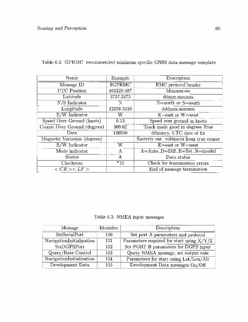
Sensing and Perception 65
Table 6.2: GPRMC recommended minimum specific GNSS data message template
Name Example Description Message ID 8GPRMC RMC protocol header
UTC Position 161229.487 hhmmss.sss Latitude 3727.2475 ddmm.mmmm
N/S Indicator N N=north or S=south Longitude 12158.3416 dddmm. mmmm
E / W Indicator W E=east or W=west Speed Over Ground (knots) 0.13 Speed over ground in knots
Course Over Ground (degrees) 309.62 Track made good in degrees True Date 120598 ddmmyy, UTC date of fix
Magnetic Variation (degrees) Easterly var. subtracts from true course E / W Indicator W E=east or W=west Mode indicator A A=Auto. ,D=Diff. ,E=Est. ,N=invalid
Status A Data status Checksum n o Check for transmission errors
< CR >< LF > End of message termination
Table 6.3: NMEA input messages
Message Identifier Description SetSerialPort 100 Set port A parameters and protocol
Navigationlnitialization 101 Parameters required for start using X/Y/Z SetDGPSPort 102 Set PORT B paramaters for DGPS input
Query/Rate Control 103 Query NMEA message, set output rate Navigationlnitialization 104 Parameters for start using Lat/Lon/Alt
Development Data 105 Development Data messages On/Off
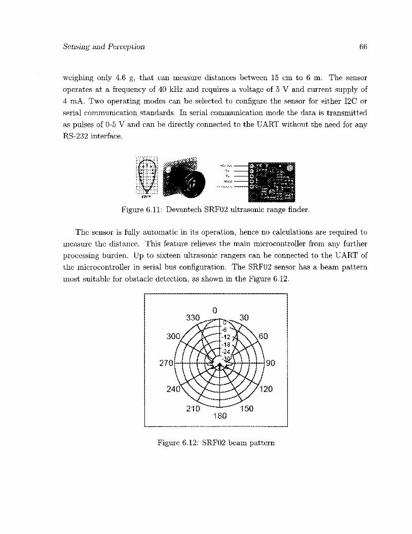
Sensing and Perception 66
weighing only 4.6 g, that can measure distances between 15 cm to 6 m. The sensor operates at a frequency of 40 kHz and requires a voltage of 5 V and current supply of 4 mA. Two operating modes can be selected to configure the sensor for either I2C or serial communication standards. In serial communication mode the data is transmitted as pulses of 0-5 V and can be directly connected to the UART without the need for any RS-232 interface.
The sensor is fully automatic in its operation, hence no calculations are required to measure the distance. This feature relieves the main microcontroller from any further processing burden. Up to sixteen ultrasonic rangers can be connected to the UART of the microcontroller in serial bus configuration. The SRF02 sensor has a beam pattern most suitable for obstacle detection, as shown in the Figure 6.12.
Figure 6.11: Devantech SRF02 ultrasonic range finder.
0 330 30
210 150 180
Figure 6.12: SRF02 beam pattern
Sensing and Perception 67
6.5 Summary
The selection of the appropriate sensors was presented with the design and development of the inertial measurement unit used for determining the attitude of the quadrotor. Complementary filters were introduced as an online attitude estimation device and their methodology was explained. The GPS used on-board the UAV was presented with the software and hardware interfacing details. Similarly, the ultrasonic range finders employed for the purpose of obstacle detection were introduced.
Chapter 7
Power Management Unit
The chapter is dedicated to the design of the hybrid power supply unit (PSU), used for driving the whole system. This innovative design comprising of lithium polymer battery and supercapacitors, to the best of our knowledge, is the first to be implemented for an aerial robot platform. Issues related to the use of battery in specific applications are highlighted in the first section. Supercapacitors are introduced and their advantages are explained in the second section. The selection process of the supercapacitors is also detailed. The design of the hybrid power supply unit is elaborated in the last section. The advantages of the proposed design for aerial robot platforms are then explained.
7.1 Power-Related Challenges
Mobile robots mostly depend on an on-board power supply for their operation. The power supply usually comprises of a battery backup for energy storage and voltage regulators for bringing the battery voltage down to different required voltage levels. Various types of batteries are available in the market offering different energy densities. Table 7.1 lists the characteristics of the most common rechargeable batteries.
Lithium Ion Polymer (Li-Po) batteries are very popular for robot applications due to their higher energy density as well as faster charging times. These features offer a significant advantage over their NiCd and NiMH counterparts.
In this research a 11.1 V, 2100 mAh, Li-Po battery is used to power the UAV. The battery offers a high energy density, however, lacks in sufficient power density for a UAV application where the propulsion unit draws large power impulses. Additionally, for a high endurance UAV, longer flight times are associated with the amount of power avail-
68

Power Management Unit 69
Table 7.1: Battery characteristic table.
Characteristics NiCd NiMH SLA Li-ion Alkaline Energy Density (Wh/kg)% 40-60 60-80 30 100 80
Internal Resistance mfl 100-300 200-800 100 300-500 200-2000 Cycle Life 1500 500 200-300 500-1000 10000
Fast Charge Time(hr) 1-1.5 2-4 8-16 3-4 2-3 Overcharge Tolerance moderate low high very low moderate
Self-discharge per month 20% 30% 5% 10% 0.3% Cell Voltage(V) 1.2 1.2 2 3.6 1.5
Charge Current(C) 2 0.5-1 0.2 1 or less 0.2 Operating Temperature(°C) -40 to 60 -20 to 60 -20 to 60 -20 to 60 0 to 65
Maintenance Required 30-60 days 60 days 3-6 months no no Typical Cost USD $50 $70 $25 $100 $5
able on-board. Typically, this issue is resolved by adding batteries in parallel resulting in increased payload at the expense of cost.
7.2 Supercapacitors
Supercapacitors, also called Ultracapacitors, are electric double layered capacitors with very higher capacitance values ranging from 1 F to 2700 F. The power density of the super capacitors, as shown in Figure 7.1, is higher than flywheels or any battery available these days. The equivalent series resistance of these huge capacitors is typically ten times smaller than the conventional capacitor. The supercapacitor technology, while offering high capacitance values, is restricted to maximum terminal values of 2.7 V. In light of this drawback, stacking of supercapacitors in series is performed to achieve higher voltages resulting in reduction of the equivalent capacitance. However, the availability of high capacitances guarantees achieving the desired capacitance and terminal voltage. Several tools are available in the market which helps the customer finding the right solution based on many types of supercapacitors.
The battery run-time is mainly dependent upon the way of the discharging, a pul-sating type load drastically reduce the run-time as compared to a constant type load. The higher power density offered by a supercapacitor makes it ideal to be used with batteries in parallel to compensate the transient power required by a pulsating load.

Power Management Unit 70
10*
1 0 '
J 10® I 103
102
10
Supercapacitom
Flywheels
Batteries 1
10 100 Energy (WWkg)
1000
Figure 7.1: Power density and energy density comparison [39].
This arrangement prevents the battery from deep discharges and results in an improved run-time.
7.3 Supercapacitor - Battery Hybrid PSU
The power requirements for the quadrotor UAV are mainly for the propulsion unit that takes the lions share of the total power. The propulsion unit requires a voltage range of 7.4-11.1 V to function properly. The current draw is dependent on the speed at which the propeller is spinning as well as the torque required for this task. From the experiments conducted on the propulsion unit the current required for generating a thrust of 200 g, using Great Planes propeller is approximately 2 A. Therefore, four propulsion units require a cumulative 8 A current generating enough thrust to overcome the weight of the quadrotor. Considering these values the calculations for designing the power system are made.
The 11.1 V Li-Po battery with 2100 mAh is sufficient to drive the four motors for 15 minutes if each draws 2 A current. To expand the UAVs time of flight, superca-pacitors are added to the PSU. The supercapacitor solution required should be able to meet the terminal voltage as well as the power draw requirements. Also the load is of pulsating nature due to the use of PWM for actuation of the BLDC motors. Therefore,

Power Management Unit 71
a capacitance value is required to provide enough power for the pulse duration which is between 1 ms to 2 ms. Another mandatory requirement is to keep the number of the supercapacitors to a minimum. The supercapacitors are used for providing higher power density and cannot offer high energy density offered by batteries as shown in Figure 7.1. Hence the weight of the added supercapacitors should be small and not to exceed the battery weight.
Tecate Group, Ultracapacitor sizing tool shown in Figure 7.2, was used in selecting the most appropriate supercapacitor solution. Five TPL-15/12X31F supercapacitors connected in series, with a cumulative capacitance of 3 F and total weight of 25 g were selected. The total equivalent series resistance of the supercapacitor bank is 0.3 and the total energy stored is 216 J.
The supercapacitor bank is connected in parallel to the Li-Po battery through a lmH inductor in a circuit very similar to the buck converter. The circuit diagram is illustrated in Figure 7.3. The supercapacitor-battery hybrid PSU will enhance the peak power output as well as reduce the internal losses due to the fact that the large amount of output current now flows through the supercapacitor.
7.4 Summary
The innovative design of the hybrid PSU comprising the Lithium Ion Polymer battery combined with the Supercapacitor bank was presented. The first of its kind design implemented on a robotic platform was used for increasing the overall operational time of the battery while prolonging battery life.
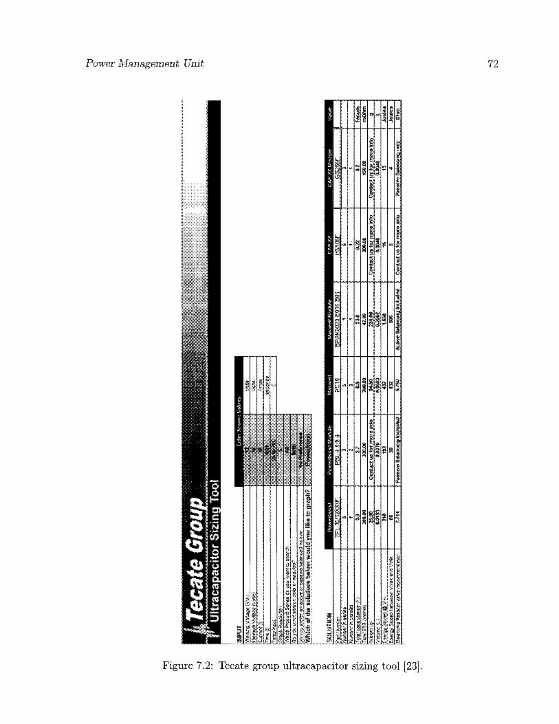
£
3 cfq' c I"!
fD
isD £ o p era
o p t-h
l-l
p o p X3
P o I—
' • <7+
o >-<
cc
n'
B'
oq
c-t- O
o (O
co
IIMPU
T iv
cxr;
/c'r
aoe
,V;-H
12
Vq
SS
* Ml
-25
to r
oc
c 0
W"
s A'
'?'-:"
3t
r ^
All
Bofii
D
o1.^
s^'
e^ar
p
a e
" -a
* eG
'^tf
te
No P
iefc
rcnc
c W
hich
of t
he s
olut
ions
bel
ow w
ould
you
lik
e to
gra
ph?
Pow
erbu
rst
SOLU
TIO
N
Pat
TPt-1
»1S3
1F
PBt,-4
.0/$.4'
PC10
BP
AK002
3 E0
15 60
1 H
ISF
GS206
F «
s S
1 i
S r-
&arase
' 1
t 3
1 i
« 'eta
"
3.0
i,l
6.0
23.0
0,22
9.2
Farad*
'eta
f"-
-reft*
' 300
.00
300.00
300
.00
42.00
200,00
150
.00
mOhm
iA
e-j-! j
js.s
e Co
ntact u
s for
more
irslo
W.50
230
.00
Contac
t us (
or m
ore inf
o Co
ntact u
t (or m
ore inf©
9
• Vhjre
"i.
0.0193
«,«
?«
fcO
Hii
s.im
O,OM
B
0JM8
L 216
192
432
1.65
6 16
13
Jou
les
|Enefc>
S'.&S
berwe
fei Vm
ax arc
VMn
66
59
132
SOS
s 4
Joules
^ 9
alaac«g
vaf
ee rec
ti 7.m
Pa
ssive B
Manon
a Incl
udes
WW
Ac
tive Ba
lancing
tac
taJe
d Conta
ct us f
or m
ore inf
o Pa
ssive B
alancing
only
Ohm
CD I (3
£ $ B
05
(3 e-t- £ to

Power Management Unit 91
Inductor 1 mH
Int. Res. 0.0075 Ohm
"Battery * 11.1V
+
! Eqv. Serbs Res. 0.3 Ohm
+ Supercapacitor 3 F
Figure 7.3: Hybrid power supply unit schematic.
Chapter 8
Experiments and Results
This chapter details the experiments conducted throughout this research and their re-sults. The first section presents the simulations carried out to test the two fuzzy flight controllers developed earlier. Both controllers are first simulated and their performances are benchmarked against various conventional control techniques. The experiments per-formed on the actual quadrotor UAV are also given with their results compared with the simulation results.
The complementary filter-based online attitude estimation method developed during the design of the IMU is tested and results are presented in the second section. The third section shows the effect of using hybrid supercapacitor-battery PSU on the overall performance and flight-time. The fourth section illustrates the flight-time increase when the helium balloon is attached to the quadrotor, hence proving the advantage of the hybrid blimp-quadrotor UAV.
8.1 Fuzzy Flight Controller Experiments
To test the proposed fuzzy logic flight controller with both inference engines and study their performances, a simulation environment is first developed. The desired inputs from the user are the translatory coordinates Pjr. with respect to the inertial frame, and the yaw angle ip. The pitch and roll angles are set to zero for achieving the desired attitude stabilization, as shall be shown later.
74

Experiments and Results 75
8.1.1 Quadrotor Simulator
The quadrotor simulator is implemented in MATLAB Simulink, as shown in Figure 8.1. The equations of motion derived in chapter 3 are used to model the quadrotor. The inputs to the quadrotor are taken as the four PWM speed values of the motors. For the simulations to be more realistic, sensory noise and environmental disturbances such as winds are also taken into account. Strong wind of 30m/s and medium wind of 10m/s, gust speeds are generated based on real data from Canada Weather Statistics [50]. The wind disturbance is incorporated as two further inputs representing the north and east wind condition. The quadrotor model outputs are the linear and angular accelerations that are integrated twice to obtain the position and orientation of the UAV.
Quadrotor Simulator Rsviiion &*t«: 25 May 200$
Enter Desired Inputs
Plottift*
Figure 8.1: MATLAB Simulink quadrotor simulator.
The values used for the quadrotor's dynamic parameters are: M = 0.765 Kg, I = 0.61 m, Jx = Jy = 0.08615 Kg-m2, Jz = 0.1712 Kg-m2, KT = 5.45, Ktau = 0.0549, Offset = Mg/{AKT) = 0.344.
The six identical fuzzy controllers are developed using MATLAB's Fuzzy Logic Tool-box, the input and output variables with membership functions described in chapter 4 are set accordingly. The fuzzy controllers are used in a configuration as shown in Figure 4.2. The inputs and outputs of the flight controller are pre-processed and post-processed

Experiments and Results 76
respectively as explained in Section 4.2. For a realistic simulation, white noise is added to the angular accelerations <p, 6 , and i p
for emulating the inertial measurement unit (IMU) sensor. The IMU signals are further processed through rate transitions to incorporate the ADC sampling rate and then used as a feedback to the fuzzy controller.
The user-defined inputs are the desired translatory coordinates Pyr. with respect to the inertial frame, and the desired yaw angle ip. The desired pitch and roll angles are implicitly set to zero to achieve attitude stabilization.
8.1.2 Simulation Experiments and Results
Three experiments are conducted on the two designed fuzzy controllers. Their respective performances are benchmarked against those of similar control schemes found in the literature.
In the first experiment, three simulations are conducted with Mamdani and Sugeno inference engines. The system's initial states are set to zero, and the desired quadrotor's position and orientation are set to P j . = [10,10, 25] m and Qjr = [0,0, 30] degrees in all three simulations. The purpose of the simulation is to assess the performance of the fuzzy logic controller and compare the accuracy of the two fuzzy inference engines under different disturbance conditions. The first simulation is run without any disturbances. In the second simulation the controller is subjected to sensor noise. In the third simulation, it is subjected to sensor noise and medium north-east wind gust of 10m/s.
The simulation results presented in Figures 8.2 and 8.3, demonstrate the ability of both controllers to perform satisfactorily despite the presence of sensor noise and wind disturbances. The Mamdani fuzzy controller converges to the desired states relatively faster than the Sugeno fuzzy controller, however Sugeno shows better attitude stabiliza-tion, specially in the presence of the sensory noise and wind disturbances.
In the second experiment, the position and attitude stabilization of the proposed con-trollers are benchmarked against feedback linearization based conventional control tech-nique, where a series of mode-based, feedback linearizing controllers are implemented for the stabilization and control of a quadrotor [1]. The system's initial states are considered to be Pf. = [40, 20, 60] m and = [45, —45, 0] degrees, similar to the experiment con-ducted in [1]. In the presence of sensor noise and wind, the system is supposed to stabilize all the states back to zero. The results depicted in Figures 8.4 and 8.5 are compared with the results of feedback linearization technique proposed in [1], shown in Figure 8.6.

Experiments and Results 77
• No noise, no wind 1 - • Noise, no wind
- • - Noise and wind
10 15 t ime (sec)
(a)
.' V ! 1 i \
1 N 1 \ . V 1 \
1 * 1
10 15 t ime (sec)
(b)
10 15 t ime (sec)
.•£ 5
1 -'l ' 1 ' 1 1 i ! IK i.. i j • i 1 i 1 i
! \ A i \ f
10 15 20 time (sec)
(c) (d)
*
. i V ,
J \ 1 : A r t nYii iV -/ . . . • ; . ) . , v M
i i i i • i i i • ; i i • i
>» 1 • i i
«
10 15 20 time (sec)
cn 20
m 15 ra
1 10
10 15 20 time (sec)
(e) (f) Figure 8.2: Experiment 1, Mamdani FLC's performance with and without disturbances. Quadrotor states: (a) x-axis; (b) y-axis; (c) z-axis (altitude); (d) pitch (8); (e) roll ((f)); and (f) yaw ( i p ) .

Experiments and Results 78
1 No noise, no wind - — - Noise, no wind
Noise and wind
10 15 t ime (sec)
(a)
10 15 t ime (sec)
(c)
1 "l
i,
1 III, 1 1 -1 1 1 I 1 I 1 ' i i • if V
15 time (sec)
/ N ' 1 'V S 1 V 1 ; ' / v 1 / > '
X ' I
10 15 t ime (sec)
(b)
» II
1 1 1 1 1 1 1 1 1 * , \ 1 '
' , .1 'L-WT— i. • /A 'A. i- , \ / V / V '
10 15 time (sec)
(d )
10 15 20 t ime (sec)
(e) ( f )
Figure 8.3: Experiment 1, Sugeno FLC's performance with and without disturbances. Quadrotor states: (a) x-axis; (b) y-axis; (c) z-axis (altitude); (d) pitch (#); (e) roll (0); and (f) yaw ( i p ) .
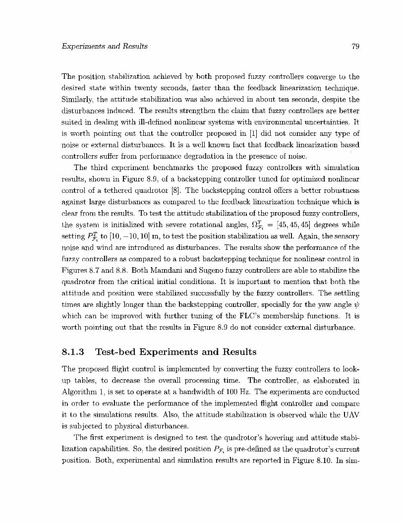
Experiments and Results 79
The position stabilization achieved by both proposed fuzzy controllers converge to the desired state within twenty seconds, faster than the feedback linearization technique. Similarly, the attitude stabilization was also achieved in about ten seconds, despite the disturbances induced. The results strengthen the claim that fuzzy controllers are better suited in dealing with ill-defined nonlinear systems with environmental uncertainties. It is worth pointing out that the controller proposed in [1] did not consider any type of noise or external disturbances. It is a well known fact that feedback linearization based controllers suffer from performance degradation in the presence of noise.
The third experiment benchmarks the proposed fuzzy controllers with simulation results, shown in Figure 8.9, of a backstepping controller tuned for optimized nonlinear control of a tethered quadrotor [8]. The backstepping control offers a better robustness against large disturbances as compared to the feedback linearization technique which is clear from the results. To test the attitude stabilization of the proposed fuzzy controllers, the system is initialized with severe rotational angles, = [45,45,45] degrees while setting P j . to [10, —10,10] m, to test the position stabilization as well. Again, the sensory noise and wind are introduced as disturbances. The results show the performance of the fuzzy controllers as compared to a robust backstepping technique for nonlinear control in Figures 8.7 and 8.8. Both Mamdani and Sugeno fuzzy controllers are able to stabilize the quadrotor from the critical initial conditions. It is important to mention that both the attitude and position were stabilized successfully by the fuzzy controllers. The settling times are slightly longer than the backstepping controller, specially for the yaw angle tp which can be improved with further tuning of the FLC's membership functions. It is worth pointing out that the results in Figure 8.9 do not consider external disturbance.
8.1.3 Test-bed Experiments and Results
The proposed flight control is implemented by converting the fuzzy controllers to look-up tables, to decrease the overall processing time. The controller, as elaborated in Algorithm 1, is set to operate at a bandwidth of 100 Hz. The experiments are conducted in order to evaluate the performance of the implemented flight controller and compare it to the simulations results. Also, the attitude stabilization is observed while the UAV is subjected to physical disturbances.
The first experiment is designed to test the quadrotor's hovering and attitude stabi-lization capabilities. So, the desired position Pjrt is pre-defined as the quadrotor's current position. Both, experimental and simulation results are reported in Figure 8.10. In sim-

Experiments and Results 80
No noise, no wind - - - Noise, no wind • — • - • Noise and wind
20 30 time (sec)
(a)
f 30
>- 10
20 30 time (sec)
(b)
Figure 8.4: Experiment 2, Mamdani FLC's performance. Quadrotor states: (a) x-axis; (b) y-axis; (c) z-axis (altitude); (d) pitch (0); (e) roll (0); and (f) yaw ( i p ) .

Experiments and Results 81
No noise, no wind - - - Noise, no wind • — • — • Noise and wind
20 30 t ime (sec)
(a)
20 30 t ime (sec)
(c)
20 30 t ime (sec)
t pi.,,
\ 1 i
30
20
10
II T> al O! C -10
c: -?n
CL
-30
-40
-50
20 30 t ime (sec)
(b)
20 30 time (sec)
(d)
(e) (f) Figure 8.5: Experiment 2, Sugeno FLC's performance. Quadrotor states: (a) x-axis; (b) y-axis;; (c) z-axis (altitude); (d) pitch (9); (e) roll (</>); and (f) yaw (-0).
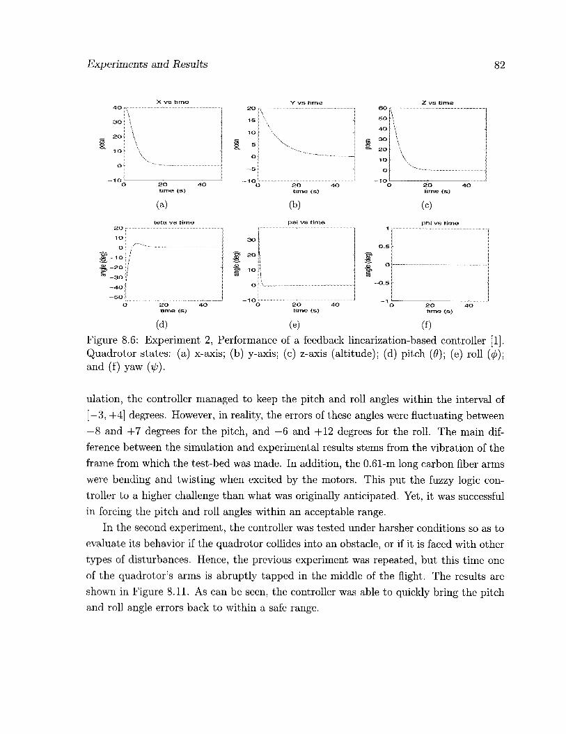
Experiments and Results 82
X vs time Y vs time Z vs time
time (s)
(a) teta vs time
SO ;
10 |
o i-
CO -301
-40 f
-so f
2 0 AO time <s)
(b)
pai vs time
30
cn 20 r <» CT> 10 TXT
O -
- I O 2 0 time (s)
SO AO time (s)
ZO 40 time {»)
2D AO time <ss)
(d) (e) (f) Figure 8.6: Experiment 2, Performance of a feedback linearization-based controller [1]. Quadrotor states: (a) x-axis; (b) y-axis; (c) z-axis (altitude); (d) pitch (0); (e) roll (0); and (f) yaw (ijj).
ulation, the controller managed to keep the pitch and roll angles within the interval of [—3, +4] degrees. However, in reality, the errors of these angles were fluctuating between —8 and +7 degrees for the pitch, and —6 and +12 degrees for the roll. The main dif-ference between the simulation and experimental results stems from the vibration of the frame from which the test-bed was made. In addition, the 0.61-m long carbon fiber arms were bending and twisting when excited by the motors. This put the fuzzy logic con-troller to a higher challenge than what was originally anticipated. Yet, it was successful in forcing the pitch and roll angles within an acceptable range.
In the second experiment, the controller was tested under harsher conditions so as to evaluate its behavior if the quadrotor collides into an obstacle, or if it is faced with other types of disturbances. Hence, the previous experiment was repeated, but this time one of the quadrotor's arms is abruptly tapped in the middle of the flight. The results are shown in Figure 8.11. As can be seen, the controller was able to quickly bring the pitch and roll angle errors back to within a safe range.

Experiments and Results 83
/ \ I v
No noise, no wind - - - Noise, no wind < - • - • Noise and wind
10 t ime (sec)
(a)
10 time (sec)
(b)
10 t ime (sec)
(c) (d)
(e) (f) Figure 8.7: Experiment 3, Mamdani FLC's performance with and without disturbances. Quadrotor states: (a) x-axis; (b) y-axis; (c) z-axis (altitude); (d) pitch (0); (e) roll ((/>); and (f) yaw ( i p ) .

Experiments and Results 84
10
9
8
_ 7 E. c 6 0 1 5 W X 4 CD H I
N 3
2
1
10 time (sec)
(c)
x: 0.4 o £
10 time (sec)
(d)
(e) ( f )
Figure 8.8: Experiment 3, Sugeno FLC's performance with and without disturbances. Quadrotor states: (a) x-axis; (b) y-axis; (c) z-axis (altitude); (d) pitch (6); (e) roll (0); and (f) yaw (-0).
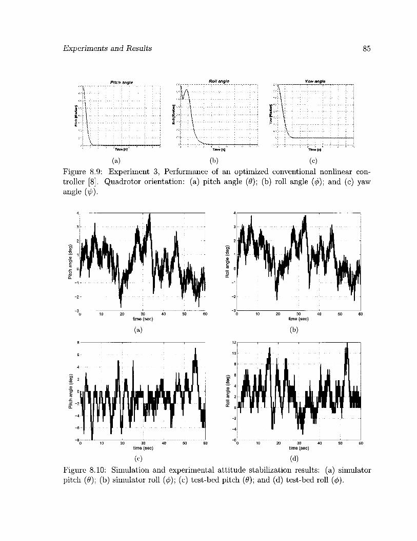
Experiments and Results 85
Pitch angle
i .
£
Roll wgi& Ymt angkt
Hm»t»|
(a) (b) (c)
Figure 8.9: Experiment 3, Performance of an optimized conventional nonlinear con-troller [8]. Quadrotor orientation: (a) pitch angle (0); (b) roll angle (</>); and (c) yaw angle (ip).
20 30 40 time (sec)
20 30 40 time (sec)
10 20 30 40 50 60 time (sec)
(b)
10 20 30 40 time (sec)
(c) (d) Figure 8.10: Simulation and experimental attitude stabilization results: (a) simulator pitch (0); (b) simulator roll (0); (c) test-bed pitch (0); and (d) test-bed roll ( ( f ) ) .

Experiments and Results 86
Algorithm 1 Quadrotor flight control algorithm
Initialize: UART 0,1,2,3 Analog and Digital Ports Timer 0,1,2,3,4 ADC clock = 125KHz PWM Timers 3,4
Body: IF (start command received) THEN Arm the motors.
Get Desired Coordinates Get GPS Coordinates Transmit GPS Coordinates ADC Gyro and Accelerometer Signals IMU Measurement Calibrations Complementary Filtering for Attitude Estimates Transmit the Attitude Estimates Pre-processing: Error and Error Rate Calculation
CALL Fuzzy Controller LUT for x, y, z, pitch, roll, and yaw states Calculate Ux, Uy, Uz, U(j), U6, Uijj Post-processing: Calculate PWM/, PWMb, PWM r , PWM, Transmit PWM speed values Set PWM timers
IF (stop command received) THEN Stop the motors. ELSE Repeat E N D
8.2 Online Attitude Estimation Results
To select the most appropriate online attitude estimation technique for the UAV (see Section 6.2), simulation experiments were conducted. Three attitude estimation tech-niques are performed on the inertial measurement data recorded from a quadrotor sim-ulator, where a simple flight maneuver is performed from an initial all zero state, such that the new position coordinates are Pjr = 0 20 0 m and the orientation VL?. =
0 0 0 . Figure 8.12 shows the six states of the UAV, where roll angle data is used

Experiments and Results 87
20
15
10
•s 5 a> T3 0 C
-5 .c o
i i -io
-15
- 2 0
-25 30 40 time (sec)
Disturbance on pitch angle
1 / >
1 Mv L :
20 30 40 time (sec)
(a) (b)
Figure 8.11: Experimental results of attitude stabilization under external disturbances: (a) test-bed pitch (0); and (b) test-bed roll ( ( f ) ) .
for the estimation experiments. The attitude estimation was required due to the fact that an attitude angle measured
using the gyroscope will suffer from a drift. Therefore, first an attitude angle data was needed, the roll angle data was selected for such purpose. The recorded roll angle gyro signal was further added with a bias of 1 deg/s to simulate the gyro bias effect. The complementary filters designed in chapter 6, and an observer were used for online estimation of the roll angle in a simulation setup.
The first order complementary filter, performs reasonably well and the estimated angle was closer to the actual. However due to the rate gyro bias integration, a ramp was generated thus adding a small steady state error to the estimate, as shown in Figure 8.13.
The second order complementary filter was able to compensate for the rate gyro bias and therefore the steady state error was annihilated successfully, as shown in Figure 8.14.
For comparison purposes, an observer was also implemented, where the gyro bias was included as a state in the state model. The apriori and aposteriori estimates were computed using a static gain. The gain matrix was obtained by placing the poles of the system such that the system had stable eigenvalues, satisfying the Lyapunov's stability criteria. The Observer simulation results were very similar to the second order comple-mentary filter performance, as depicted in the Figure 8.15. The convergence rate can be improved by making appropriate changes to the gain, however this results in making the output sensitive to the acceleration measurement, leading to errors in the angle estimate. The gyro bias estimate convergence to the actual bias value is shown in Figure 8.16.
Simulation results show that the second-order complementary filter successfully re-

Experiments and Results 88
(a)
(c)
(e)
Figure 8.12: Quadrotor motion plots, (a) pitch ( 9 ) ; (e) roll (</>); and (f) yaw ( i j j ) .
25
- 5 1 . i i , i , 1 0 5 10 15 20 25 30 35
time (sec)
(b)
1
y, A ' ;
I A/if i f V l y || V
' 1 0 5 10 15 20 25 30 35
time (sec)
(d)
(f) x-axis; (b) y-axis; (c) z-axis (altitude); (d)

Experiments and Results 107
o <s to "B CD L_ D) CD
W C CO
CO 0} to 0C 2 CD
— Actual Angle 1 - • - • Angle with Bias - - - 1st Order Complementary Filter Estimate
15 20 Time (sec)
Figure 8.13: First order complementary filter estimate vs the actual angle.
40 • Actual Angle • Angle with Bias • 2nd Order Complementary Filter Estimate
15 20 Time (sec)
Figure 8.14: Second order complementary filter estimate vs the actual angle.

Experiments and Results 90
- 2 0 L
10 15 20 T i m e (sec)
25 30 35
Figure 8.15: Observer estimate and the actual angle.
c E
onstant Bias stimated Bias
i » » / J J 1
!\ > i • i
t l , ' 1
1
• i • i • i
. • i 1
l \ J i
• \ i \ i r
/ t
T i m e (sec)
Figure 8.16: Rate gyro bias estimate from observer and the actual constant bias value.

Experiments and Results 91
moves the gyro bias and provides a better estimate of the angle as compared to a first order complementary filter. Also, the results were very similar to that of an observer. The design criteria considered here is such that the method should be easier to imple-ment and lighter in terms of complexity, hence feasible for embedded platforms with limited resources. Therefore, second-order complementary filters were adopted for online attitude estimation of the quadrotor UAV.
8.3 Increased Flight-time using Hybrid PSU
Three experiments were performed to observe the advantages of the designed hybrid PSU over batteries alone. But first, the power requirements and limitations of the system were noted prior to conducting any experiments. The current drawn by the quadrotor's four ESCs in a passive state was noted to be 60 mA. This power draw is due to the built-in 5 V voltage regulators present in each of the ESCs. Once powered, but without the motors running, the system draws 300 mA, including the Axon board, the IMU, GPS, and the four ESCs. Each motor draws 2.4 A current to generate enough thrust to lift the quadrotor weighing 924 g. Therefore, the cumulative current required to keep the quadrotor in flight is calculated to be 9.9 A.
A 3S Lithium-ion Polymer battery of 11.1 V and 2100 mAh capacity was used for these experiments. For safety requirements, the Lithium-ion battery cells should not be allowed to discharge below 3.0 V. The battery used has three cells in series, hence at 9.0 V the system is suppose to shut down. Therefore, the effective terminal voltage of the battery ranges from 11.1 V to 9.0 V.
The first experiment was conducted to compare the run-time performance of the power supply unit, with and without the supercapacitor bank. For the experimental setup, a switch is introduced in the PSU circuit, in order to include the supercapacitor bank for the first part of the experiment, and later disconnect it so that the UAV is powered by the battery only. A 11.1 V, 2100 mAh Lithium-ion Polymer battery was charged using a battery charger capable of cell balancing for optimal charging. The initial voltage of the battery was recorded to be 11.36 V. The experiment was run until the battery voltage dropped by 1 volt. The terminal voltage of the battery was then recorded using a voltmeter at time intervals of 30 seconds. The UAV was programmed to run all four motors at the same speed below hovering. For the second part, the same procedure was repeated, however, the switch was toggled in order to disconnect the supercapacitor bank from the PSU. The recorded experimental observations are presented in Figure 8.17.

Experiments and Results 92
PSU with Supercapacitor Bank PSU without Supercapacitor Bank
1000 1500 Time (sec)
1000 1500 Time (sec)
(a) (b)
Figure 8.17: Results of run-time for 1 V battery voltage drop: (a) With Supercapacitor bank; and (b) Without Supercapacitor bank.
The experimental results indicate no significant difference in battery run-time for both parts of the experiment. However, it is important to note that a run-time of 31 minutes and 30 seconds was achieved while the battery voltage dropped from 11.36 volts to 10.36 volts. The UAV was capable of further operation until the battery voltage drops to 9 volts, where it is necessary for a Lithium-ion Polymer battery to be recharged.
The second experiment was performed to observe the performance of the hybrid PSU under a pulsed load. A Lithium-ion Polymer battery model was used in a simulation environment, due to the lack of battery monitoring equipment, so that a detailed perfor-mance study of the battery can be conducted. The hybrid PSU was recreated using the PowerSim toolbox of Simulink, in MATLAB. Brushless DC motor models with PWM based speed control were used as the pulsed load. The battery was monitored for the state of its charge, terminal voltage and the supplied current. The experiment was run for a total of 10 seconds, during the first 5 seconds of which the Supercapacitor bank is allowed to charge. On the 5th second, motors are powered on for the remaining time. The experiment was repeated twice, first with the Supercapacitor bank included in the circuit, and then with the Supercapacitor bank disconnected from the PSU circuit. The noted observation are plotted in Figures 8.18 to 8.19.
The experimental results shown in Figures 8.18(b) and 8.18(d) paint a different pic-ture as compared to the first experiment. A significant improvement was observed in battery performance when the Supercapacitor bank was included in the hybrid PSU cir-cuit. When the system is operated without the Supercapacitor bank the battery voltage

Experiments and Results 93
PSU with Supercapacitor Bank - Battery Voltage
> 11
>
PSU without Supercapacitor Bank - Battery Voltage
4 6 Time (sec)
(a)
PSU with Supercapacitor Bank - Battery Current
(b)
PSU without Supercapacitor Bank - Battery Current
Time (sec)
(c) (d) Figure 8.18: Hybrid PSU experimental results: (a) Battery voltage; (b) Battery voltage; (c) Battery current; and (d) Battery current.
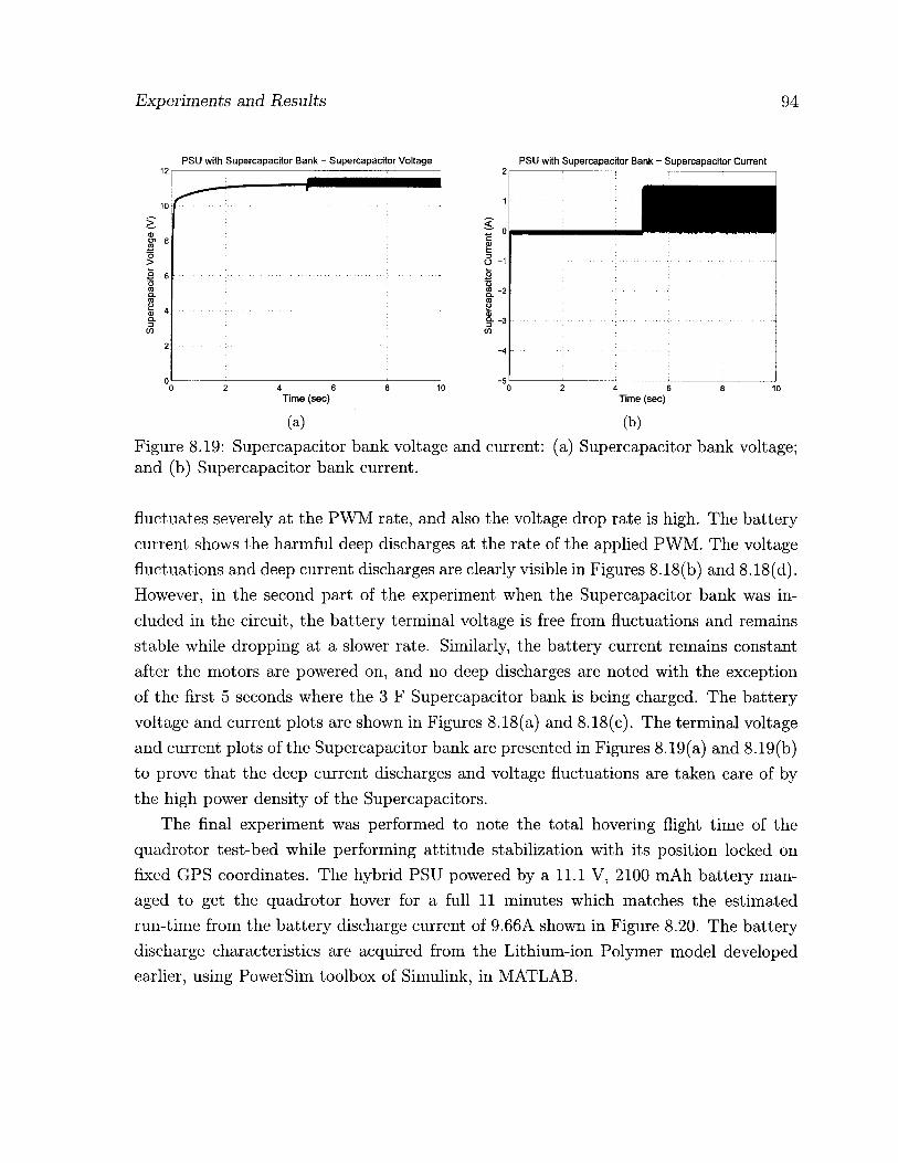
Experiments and Results 94
PSU with Supercapacitor Bank - Supercapacitor Voltage PSU with Supercapacitor Bank - Supercapacitor Current
Time (sec)
t 3 -1 to -2
Time (sec)
(a) (b)
Figure 8.19: Supercapacitor bank voltage and current: (a) Supercapacitor bank voltage; and (b) Supercapacitor bank current.
fluctuates severely at the PWM rate, and also the voltage drop rate is high. The battery current shows the harmful deep discharges at the rate of the applied PWM. The voltage fluctuations and deep current discharges are clearly visible in Figures 8.18(b) and 8.18(d). However, in the second part of the experiment when the Supercapacitor bank was in-cluded in the circuit, the battery terminal voltage is free from fluctuations and remains stable while dropping at a slower rate. Similarly, the battery current remains constant after the motors are powered on, and no deep discharges are noted with the exception of the first 5 seconds where the 3 F Supercapacitor bank is being charged. The battery voltage and current plots are shown in Figures 8.18(a) and 8.18(c). The terminal voltage and current plots of the Supercapacitor bank are presented in Figures 8.19(a) and 8.19(b) to prove that the deep current discharges and voltage fluctuations are taken care of by the high power density of the Supercapacitors.
The final experiment was performed to note the total hovering flight time of the quadrotor test-bed while performing attitude stabilization with its position locked on fixed GPS coordinates. The hybrid PSU powered by a 11.1 V, 2100 mAh battery man-aged to get the quadrotor hover for a full 11 minutes which matches the estimated run-time from the battery discharge current of 9.66A shown in Figure 8.20. The battery discharge characteristics are acquired from the Lithium-ion Polymer model developed earlier, using PowerSim toolbox of Simulink, in MATLAB.

Experiments and Results 95
13
12
<i> 11 oi CO 15 10 >
9
8
E0 = 11.2671, R = 0.049524, K = 0.027956, A = 0.88357, B = 29.0771
12
CO ? 10 >
9
8 0 1 2 3 4 5 6 7 8 9 10 11 12 13 14 15 16 17 18 19
Time (Minutes)
Figure 8.20: 2100 mAh battery discharge characteristics.
8.4 Increased Flight-time using Helium Balloon
An experiment was performed to observe the increase in flight-time when helium bal-loon was attached to the quadrotor UAV. Two helium balloons were designed using polyurethane material of different thickness. A thickness of 2 mil was finally chosen owing to its lighter weight of 100 g therefore yielding greater buoyancy then the balloon with a 4 mil thickness. The quadrotor mass is 740 g without the 215 g battery. The hybrid quadrotor-blimp design including the battery and the helium envelope total to 1054 g.
The helium acquired for the experiment was from a local party store and was not pure helium. The cumulative buoyancy lift generated by the helium filled envelope was measured to be 57 g after canceling its own 100 g mass. To observe the flight-time of quadrotor attached with the helium balloon, the experiment conducted in previous section was repeated. The flight-time this time was measured to be 11 minutes and 30 seconds, which yields an improvement of 4.5X.
Nominal Current Discharge Charactenstic at 0.43478C (0.91304A) I i
Discharge curve -
V : • H i m Exponential area -
i i 0.5 1 1.5 2 2.5 3
Time (hours)
I ! I 9.66 A 10.3 A 11.1 A
-
i 9.66 A 10.3 A 11.1 A
-
\
9.66 A 10.3 A 11.1 A
-
\ \
\ \
\ S
. . . Y v

Experiments and Results 96
8.5 Summary
The experiments and their results were presented in this chapter. The fuzzy flight con-trollers designed earlier were tested for performance, first in a simulation environment and later on a real test-bed. The results were compared with conventional control coun-terparts and a successful and robust flight performance of the proposed fuzzy flight controller was observed. The quadrotor UAV was also able to stabilize its attitude when subjected to physical disturbances. Simulation results for the adopted attitude estima-tion methodology based on complementary filtering was also illustrated. The comple-mentary filters were successfully used for combining the angle estimate from the rate gyro and accelerometer, while filtering out the rate gyro bias and noise from the accelerometer measurements. Finally, the flight-time increase using the proposed hybrid PSU and the helium envelope were calculated. It is clear from the results that although the increase of flight-time using hybrid PSU was negligible, its real advantage was in providing the high power density, and therefore safeguarding the battery from deep current discharges, thus prolonging its life. The flight-time increase using the helium envelope was only 30 sec-ond. However, this can be significantly improved by further optimizing the quadrotor's weight or increasing the size of the helium balloon.

Chapter 9
Conclusion
This research addresses the problem of autonomous flight control of a hybrid quadrotor UAV. Detailed mathematical modeling of the quadrotor's kinematics and dynamics was provided. A modular fuzzy logic approach was proposed for the autonomous control of quadrotor's in general, without the need for a precise mathematical model of their complex and ill-defined dynamics. The fuzzy technique was implemented through Mam-dani and TSK inference engines for comparison purposes. The controller comprises six individual fuzzy logic modules designated for the control of the quadrotor's position and orientation. The investigation on the two types of control methodologies was conducted in a simulator environment, where disturbances such as wind conditions and sensor noise were incorporated for a more realistic simulation. The fuzzy flight controller was eventu-ally implemented on a quadrotor test-bed specifically designed and built for the project.
The experiments were first conducted on the simulator before being validated on the test-bed. The results demonstrated a successful control performance under both inference engines. When compared to other conventional techniques applied for a sim-ilar purpose [1], [8], the proposed methodology showed a higher robustness despite the induced disturbances.
Some inherent issues with the quadrotor design were also elaborated and method-ologies were proposed to modify the conventional design of quadrotor for improvements. Experiments demonstrate an insignificant increase in flight-time after implementing the proposed hybrid blimp-quadrotor design. The flight-time achieved can be further in-creased by replacing suggested components mentioned in Table 9.1 to reduce the overall weight of the UAV. Also, a bigger size balloon filled with pure helium was recommended to achieve optimal flight-time performance. Recommendations were made to improve
97
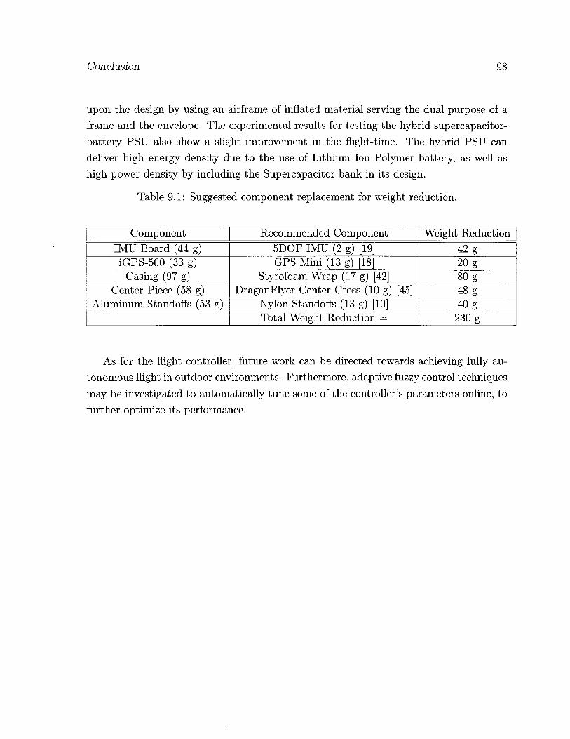
Conclusion 98
upon the design by using an airframe of inflated material serving the dual purpose of a frame and the envelope. The experimental results for testing the hybrid supercapacitor-battery PSU also show a slight improvement in the flight-time. The hybrid PSU can deliver high energy density due to the use of Lithium Ion Polymer battery, as well as high power density by including the Supercapacitor bank in its design.
Table 9.1: Suggested component replacement for weight reduction.
Component Recommended Component Weight Reduction IMU Board (44 g) 5DOF IMU (2 g) [19] 42 g iGPS-500 (33 g) GPS Mini (13 g) [18] 20 g
Casing (97 g) Styrofoam Wrap (17 g) [42] 80 g Center Piece (58 g) DraganFlyer Center Cross (10 g) [45] 48 g
Aluminum Standoffs (53 g) Nylon Standoffs (13 g) [10] 40 g Total Weight Reduction = 230 g
As for the flight controller, future work can be directed towards achieving fully au-tonomous flight in outdoor environments. Furthermore, adaptive fuzzy control techniques may be investigated to automatically tune some of the controller's parameters online, to further optimize its performance.

Bibliography
[1] E. Altug, J.P. Ostrowski, and R. Mahony. Control of a quadrotor helicopter us-ing visual feedback. In Proceedings of the 2002 IEEE International Conference on Robotics and Automation, pages 72-77, Washington, May 2002. IEEE.
[2] F. Archer, A. Shutko, T. Coleman, A. Haldin, E. Novichikhin, and I. Sidorov. Intro-duction, overview, and status of the microwave autonomous copter system MACS. Proceedings of the 2004 IEEE International Geoscience and Remote Sensing Sym-posium., 5:3574-3576, Sep 2004.
[3] M. D. Ardema. Vehicle concepts and technology requirements for buoyant heavy-lift systems. NASA Technical Paper, 1921.
[4] Randal W. Beard. Quadrotor dynamics and control. Brigham Young University, February 19 2008. lecture notes.
[5] A. Benallegue, A. Mokhtari, and L. Fridman. High-order sliding-mode observer for a quadrotor UAV. International Journal of Robust and Nonlinear Control, 18(4-5):427-440, 2008.
[6] S. Bouabdallah. Design and control of quadrotors with application to autonomous flying. Master's thesis, Swiss Federal Institute of Technology, 2007.
[7] S. Bouabdallah, P. Murrieri, and R. Siegwart. Design and control of an indoor micro quadrotor. In Proceedings of the International Conference on Robotics and Automation, 2004.
[8] S. Bouabdallah, A. Noth, and R. Siegwart. PID vs LQ control techniques applied to an indoor micro quadrotor. In International Conference on Intelligent Robots and Systems, 2004.
99

Conclusion 100
[9] H. Bouadi, M. Bouchoucha, and M. Tadjine. Sliding mode control based on back-stepping approach for an UAV type-quadrotor. Proceedings of World Academy of Science, Engineering and Technology, 20:22-27, 2007.
[10] Newark Canada. Nylon standoff. [Online] Available, December 2009. http://canada.newark.com/keystone/1902a/standoff/dp/94F4404.
[11] J. Casper and R. R. Murphy. Humanrobot interactions during the robot-assisted urban search and rescue response at the World Trade Center. IEEE Transactions on Systems, Man, and Cybernetics, 33(3):367-385, June 2003.
[12] F. B. Qamlica. Demonstration of a stabilized hovering platform for undergraduate laboratory. Master's thesis, The Graduate School of Natural and Applied Sciences of Middle East Technical University, December 2004.
[13] M. Chen and M. Huzmezan. A combined MBPC/ 2 DOF h ^ controller for a quad rotor UAV. In AIAA Guidance, Navigation, and Control Conference and Exhibit, Austin, Texas, August 2003.
[14] C. Coza and C.J.B. Macnab. A new robust adaptive-fuzzy control method applied to quadrotor helicopter stabilization. In Annual meeting of the North American Fuzzy Information Processing Society, pages 454-458, 2006.
[15] R. A. Dougal, Shengyi Liu, and Ralph E. White. Power and life extension of bat-teryultracapacitor hybrids. IEEE Transactions on Components and Packaging Tech-nologies, 25(1):120-131, March 2002.
[16] A. Dzul, P. Castillo, and R. Lozano. Real-time stabilization and tracking of a four-rotor mini rotorcraft. IEEE Transaction on Control System Technology, 12(4):510-516, 2004.
[17] E. J. P. Earon, C. Rabbath, and J. Apkarian. Design and control of a novel hy-brid vehicle concept. In AIAA Guidance, Navigation, and Control Conference and Exhibit, Austin, Texas, August 2007.
[18] SparkFun Electronics. Gps micro-mini. [Online] Available, December 2009. http://www.sparkfun.com.
[19] SparkFun Electronics. Imu 6dof razor - ultra-thin imu. [Online] Available, December 2009. http://www.sparkfun.com.

Conclusion 101
[20] T. Fincannon, L. E. Barnes, R. R. Murphy, and D. L. Riddle. Evidence of the need for social intelligence in rescue robots. Proceedings of 2004 IEEE/RSJ In-ternational Conference on Intelligent Robots and Systems, pages 1089-1095, 2004. Sendai, Japan.
S. G. Fowers. Stabilization and control of a quad-rotor micro-UAV using vision sensors. Master's thesis, Brigham Young University, August 2008.
J. M. Grasmeyer and M. T. Keennon. Development of the black widow micro air vehicle. In 39th AIAA Aerospace Sciences Meeting and Exhibit, 2001.
Tecate Group. Tecate ultracapacitor design tool. [Online] Available, September 2009. http://www.tecategroup.com/ultracapacitors/designtool.php.
N. Guenard, T. Hamel, and R. Mahony. A practical visual servo control for an unmanned aerial vehicle. IEEE Transactions on Robotics, 24(2):331-340, 2008.
N. Guenard, T. Hamel, and V. Moreau. Dynamic modeling and intuitive control strategy for an X4-flyer. ICCA '05. International Conference on Control and Au-tomation, 1:141-146, June 2005.
S. D. Hanford. A small semi-autonomous rotary-wing unmanned air vehicle. Mas-ter's thesis, Pennsylvania State University, December 2005.
G. M. Hoffmann, S.W. Waslander, and C.J. Tomlin. STARMAC 2 quadrotor heli-copters, November 2007.
J.P. How, B. Bethke, A. Frank, D. Dale, and J. Vian. Real-time indoor autonomous vehicle test environment. IEEE Control Systems Magazine, 28(2):51-64, April 2008.
Draganfly Innovations Inc. Industrial aerial video systems and UAVs, October 2008.
Lubin Kerhuel. Miniature inertial measurement unit. http://www.kerhuel.eu/wiki/index.php5, April 2009.
G. A. Khoury and J. D. Gillett. Airship Technology. CAMBRIDGE UNIVERSITY PRESS, Cambridge, UK, first edition, 1999.
A.O. Kivrak. Design of control systems for a quadrotor flight vehicle equipped with inertial sensors. Master's thesis, The Graduate School of Natural and Applied Sciences of Atilim University, December 2006.

Conclusion 102
[33] I. Kroo. The mesicopter: A meso-scale flight vehicle- niac phase i final report, 2001.
[34] J. G. Leishman. The breguet-richet quad-rotor helicopter of 1907, 1907.
[35] L. Ljung. System Identification: Theory for the User. Prentice Hall, Inc., Englewood Cliffs, NJ 07632, USA, 1987.
[36] R. Mahony, T. Hamel, and J.M. Pflimlin. Nonlinear complementary filters on the special orthogonal group. IEEE Transactions on Automatic Control, 53(5):1203-1218, June 2008.
[37] E.H. Mamdani. An experiment in linguistic synthesis with a fuzzy logic controller. International Journal of Man-Machine Studies, 7(1):1—13, 1975.
[38] J. M. McMichael and M. S. Francis. Micro air vehicles - toward a new dimension in flight, 1997.
[39] N. Mohan, T. M. Underland, and W. P. Robins. Power Electronics, Converters, Applications and Design. John Wiley and Sons, New York, USA, first edition, 1995.
[40] L. R. Newcome. Unmanned aviation: A brief history of unmanned aerial vehicles. American Institute of Aeronautics and Astronautics, Inc., Reston, Va, 2004.
[41] U.S. Department of Defense. Unmanned systems roadmap 2007 — 2032, 2007.
[42] IPS Packaging. Instafoam packaging. [Online] Available, December 2009. http: / / www.ipack.com/shop/department/foam-in-place-4176.cfm.
[43] L. Palma, P. Enjeti, and J.W. Howze. An approach to improve battery run-time in mobile applications with supercapacitors. In Proceedings of Power Electronics Specialists Conference, 2003. pesc 03. 2003 IEEE 34th Annual, volume 2, pages 918- 923. IEEE, June 2003.
[44] D. J. Pines and F. F. Bohorquez. Challenges facing future micro-air-vehicle devel-opment. Journal of Aircraft, 43(2):290-305, 2006.
[45] RCToys. Draganflyer frame center cross. [Online] Available, Decem-ber 2009. http://www.rctoys.com/rc-toys-and-parts/DF-CROSS/RC-PARTS-DRAGANFLYER-FRAME.html.

Conclusion 103
[46] J. Rumerman. Helicopter development in the early twentieth century. [Online] Available, December 2002.
[47] S. Salcudean. A globally convergent angular velocity observer for rigid body motion. IEEE Transactions on Automatic Control, 36(12): 1493-1497, December 1991.
[48] NOAA Satellite and Information Service. NOAA search and rescue satellite-aided tracking, September 2008.
[49] T.A. Smith, J.P. Mars, and G.A. Turner. Using supercapacitors to improve battery performance. In Proceedings of Power Electronics Specialists Conference, 2002. pesc 02. 2002 IEEE 33rd Annual, volume 1, pages 124- 128. IEEE, November 2002.
[50] Canada Weather Statistics. Courtesy of environment canada. [Online] Available, February 2009. http://www.weatherstats.ca/.
[51] M. Sugeno. Industrial applications of fuzzy control. Elsevier Science Pub. Co., NewYork, NY, 1985.
[52] R. Sugiura, T. Fukagawa, N. Noguchi, K. Ishii, Y. Shibata, and K. Toriyama. Field information system using an agricultural helicopter towards precision farming. Pro-ceedings of the 2003 IEEE/ASME International Conference on Advanced Intelligent Mechatronics, 2:1073-1078, July 2003.
[53] M. Tarbouchi, J. Dunfied, and G. Labonte. Neural network based control of a four rotor helicopter. In International Conference on Industrial Technology, pages 1543-1548, 2004.
[54] A. Tayebi and S. McGilvray. Attitude stabilization of a vtol quadrotor aircraft. IEEE Transaction on Control System Technology, 14(3):562-571, May 2006.
[55] J. Thienel and R.M. Sanner. A coupled nonlinear spacecraft attitude controller and observer with an unknown constant gyro bias and gyro noise. IEEE Transactions on Automatic Control, 48(11):2011-2015, November 2003.
[56] Hybrid Air Vehicles. Revolutionary aerospace solutions for transport, surveillance and telecommunications in the 21st century. [Online] Available, February 2009. http: / / www. hybridair vehicles. net / .

Conclusion 104
[57] S. L. Waslander, G. M. Hoffmann, J. S. Jang, and C. J. Tomlin. Multi-agent quadrotor testbed control design: integral sliding mode vs. reinforcement learning. 2005 IEEE/RSJ International Conference on Intelligent Robots and Systems, pages 468-473, 2005.
[58] K. W. Weng and M. Shukri. Design and control of a quad-rotor flying robot for aerial surveillance. Student Conference on Research and Development (SCOReD 2006), pages 173-177, 2006.
[59] L.A. Zadeh. Fuzzy sets. Information and Control, 8:338-353, 1965.