digitax st user guide issue 5 - epa gmbh · 4 digitax st user guide issue: 5 ... 3.3 solutions...
TRANSCRIPT
User Guide
AC variable speed drive for servo motors

Original InstructionsFor the purposes of compliance with the EU Machinery Directive 2006/42/EC:
General InformationThe manufacturer accepts no liability for any consequences resulting from inappropriate, negligent or incorrect installation or adjustment of the optional operating parameters of the equipment or from mismatching the variable speed drive with the motor.
The contents of this guide are believed to be correct at the time of printing. In the interests of a commitment to a policy of continuous development and improvement, the manufacturer reserves the right to change the specification of the product or its performance, or the contents of the guide, without notice.
All rights reserved. No parts of this guide may be reproduced or transmitted in any form or by any means, electrical or mechanical including photocopying, recording or by an information storage or retrieval system, without permission in writing from the publisher.
Drive software versionThis product is supplied with the latest software version. If this drive is to be connected to an existing system or machine, all drive software versions should be verified to confirm the same functionality as drives of the same model already present. This may also apply to drives returned from an Emerson Industrial Automation Service Centre or Repair Centre. If there is any doubt please contact the supplier of the product.
The software version of the drive can be checked by looking at Pr 11.29 and Pr 11.34. This takes the form of xx.yy.zz where Pr 11.29 displays xx.yy and Pr 11.34 displays zz. (e.g. for software version 01.01.00, Pr 11.29 = 1.01 and Pr 11.34 displays 0).
Environmental statementEmerson Industrial Automation is committed to minimising the environmental impacts of its manufacturing operations and of its products throughout their life cycle. To this end, we operate an Environmental Management System (EMS) which is certified to the International Standard ISO 14001. Further information on the EMS, our Environmental Policy and other relevant information is available on request, or can be found at:
http://www.emersonindustrial.com/en-EN/controltechniques/aboutus/environment/Pages/environment.aspx
The electronic variable-speed drives manufactured by Emerson Industrial Automation have the potential to save energy and (through increased machine/process efficiency) reduce raw material consumption and scrap throughout their long working lifetime. In typical applications, these positive environmental effects far outweigh the negative impacts of product manufacture and end-of-life disposal.
Nevertheless, when the products eventually reach the end of their useful life, they must not be discarded but should instead be recycled by a specialist recycler of electronic equipment. Recyclers will find the products easy to dismantle into their major component parts for efficient recycling. Many parts snap together and can be separated without the use of tools, while other parts are secured with conventional fasteners. Virtually all parts of the product are suitable for recycling.
Product packaging is of good quality and can be re-used. Large products are packed in wooden crates, while smaller products come in strong cardboard cartons which themselves have a high recycled fibre content. If not re-used, these containers can be recycled. Polythene, used on the protective film and bags for wrapping product, can be recycled in the same way. Emerson Industrial Automations' packaging strategy prefers easily-recyclable materials of low environmental impact, and regular reviews identify opportunities for improvement.
When preparing to recycle or dispose of any product or packaging, please observe local legislation and best practice.
REACH legislationEC Regulation 1907/2006 on the Registration, Evaluation, Authorisation and restriction of Chemicals (REACH) requires the supplier of an article to inform the recipient if it contains more than a specified proportion of any substance which is considered by the European Chemicals Agency (ECHA) to be a Substance of Very High Concern (SVHC) and is therefore listed by them as a candidate for compulsory authorisation.
For current information on how this requirement applies in relation to specific Emerson Industrial Automations’ products, please approach your usual contact in the first instance. Emerson Industrial Automations’ position statement can be viewed at:
www.emersonindustrial.com/en-EN/controltechniques/aboutus/environment/reachregulation/Pages/reachregulation.aspx.
Copyright © September 2015 Emerson Industrial Automation.
The information contained in this guide is for guidance only and does not form part of any contract. The accuracy cannot be guaranteed as Emerson have an ongoing process of development and reserve the right to change the specification of their products without notice.
Control Techniques Limited. Registered Office: The Gro, Newtown, Powys SY16 3BE. Registered in England and Wales. Company Reg. No. 01236886.
Moteurs Leroy-Somer SAS. Headquarters: Bd Marcellin Leroy, CS 10015, 16915 Angoulême Cedex 9, France. Share Capital: 65 800 512 €, RCS Angoulême 338 567 258.
Issue Number: 5
Software: 01.06.00 onwards
For patent and intellectual property related information please go to: www.ctpatents.info.
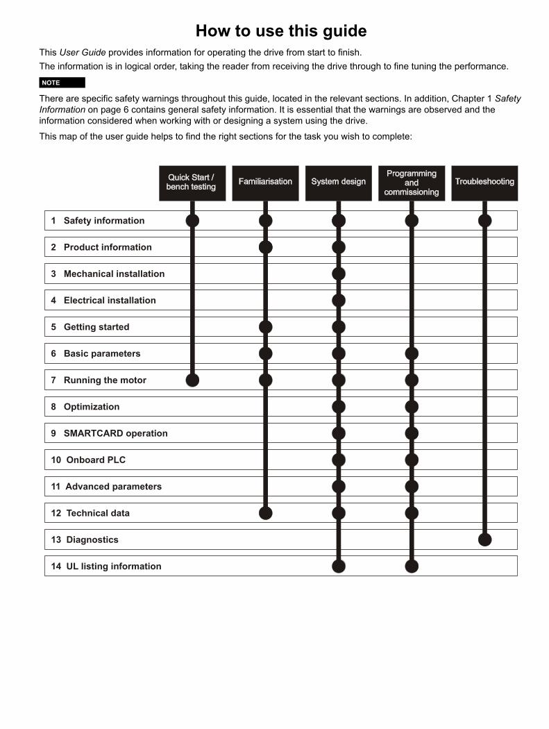
How to use this guideThis User Guide provides information for operating the drive from start to finish. The information is in logical order, taking the reader from receiving the drive through to fine tuning the performance.
There are specific safety warnings throughout this guide, located in the relevant sections. In addition, Chapter 1 Safety Information on page 6 contains general safety information. It is essential that the warnings are observed and the information considered when working with or designing a system using the drive.
This map of the user guide helps to find the right sections for the task you wish to complete:
NOTE
1 Safety information
2 Product information
3 Mechanical installation
4 Electrical installation
5 Getting started
6 Basic parameters
7 Running the motor
8 Optimization
9 SMARTCARD operation
11 Advanced parameters
12 Technical data
13 Diagnostics
14 UL listing information
10 Onboard PLC
Contents
1 Safety Information .................................61.1 Warnings, Cautions and Notes .............................61.2 Electrical safety - general warning ........................61.3 System design and safety of personnel ................61.4 Environmental limits ..............................................61.5 Access ...................................................................61.6 Fire protection .......................................................61.7 Compliance with regulations .................................61.8 Motor .....................................................................61.9 Mechanical brake control ......................................61.10 Adjusting parameters ............................................61.11 Electrical installation ..............................................6
2 Product information ..............................82.1 Introduction ...........................................................82.2 Drive ratings ..........................................................82.3 Drive model numbers ............................................92.4 Drive nameplate description ..................................92.5 Features of the drive ...........................................102.6 Options ................................................................112.7 Items supplied with the drive ...............................14
3 Mechanical installation .......................153.1 Safety information ...............................................153.2 Planning the installation ......................................153.3 Solutions Module / keypad installation / removal 163.4 Drive dimensions .................................................173.5 External EMC filter rating ....................................183.6 Optional braking resistor .....................................193.7 Terminal torque settings ......................................203.8 Routine maintenance ..........................................20
4 Electrical installation ...........................214.1 Power terminal connections ................................224.2 Ground connections ............................................234.3 AC supply requirements ......................................234.4 DC bus design .....................................................244.5 DC drive voltage levels .......................................244.6 Ratings ................................................................254.7 Output circuit and motor protection .....................254.8 Braking ................................................................264.9 Ground leakage ...................................................274.10 EMC (Electromagnetic compatibility) ..................284.11 Internal and external conducted emissions
conformity ............................................................304.12 Serial communications connections ....................314.13 Control connections ............................................324.14 Control terminals .................................................344.15 Encoder connections ...........................................374.16 Encoder terminals ...............................................384.17 Safe Torque Off ...................................................42
5 Getting started .................................... 435.1 User interfaces ................................................... 435.2 CT Soft ............................................................... 435.3 SYPTPro (Indexer & Plus only) .......................... 435.4 EZMotion PowerTools Pro ................................. 435.5 Keypad operation ............................................... 445.6 Understanding the display .................................. 445.7 Displaying parameters with non-default
values only ......................................................... 475.8 Displaying destination parameters only ............. 475.9 Communications ................................................ 47
6 Basic parameters ................................ 496.1 Single line descriptions ...................................... 496.2 Full descriptions ................................................. 54
7 Running the motor .............................. 607.1 Quick start Connections ..................................... 607.2 Quick Start set-up .............................................. 647.3 Setting up a feedback device ............................. 657.4 Setting up a buffered encoder output ................. 68
8 Optimization ........................................ 698.1 Motor map parameters ....................................... 69
9 EtherCAT interface ............................. 729.1 Features ............................................................. 729.2 What is EtherCAT? ............................................ 729.3 EtherCAT interface information .......................... 729.4 EtherCAT interface terminal descriptions ........... 729.5 Module grounding .............................................. 729.6 Network topology ............................................... 729.7 Minimum node-to-node cable length .................. 729.8 Quick start guide ................................................ 729.9 Quick start flowchart ........................................... 749.10 Saving parameters to the drive .......................... 759.11 EtherCAT interface Node address ..................... 759.12 EtherCAT interface RUN .................................... 759.13 Re-initializing the EtherCAT interface ................ 759.14 Process Data Objects (PDOs) ........................... 759.15 Service Data Object (SDO) parameter access .. 759.16 CANopen over EtherCAT (CoE) ........................ 769.17 Ethernet over EtherCAT (EoE) ........................... 809.18 Drive profile (DSP-402) support ......................... 819.19 Interpolated position mode ................................. 879.20 vl velocity mode .................................................. 889.21 Profile torque mode ............................................ 909.22 Homing mode ..................................................... 919.23 Cyclic sync position mode .................................. 949.24 Advanced features ............................................. 949.25 Advanced cyclic data configuration .................... 969.26 Internal shortcuts ................................................ 979.27 Quick reference .................................................. 98
4 Digitax ST User Guide Issue: 5

10 SMARTCARD Operation ...................10110.1 Introduction .......................................................10110.2 Transferring data ...............................................10210.3 Data block header information ..........................10410.4 SMARTCARD parameters ................................10410.5 SMARTCARD trips ...........................................106
11 Onboard PLC .....................................10811.1 Onboard PLC and SYPTLite .............................10811.2 Benefits .............................................................10811.3 Limitations .........................................................10811.4 Getting started ..................................................10811.5 Onboard PLC parameters .................................10811.6 Onboard PLC trips ............................................10911.7 Onboard PLC and the SMARTCARD ...............109
12 Advanced parameters .......................11012.1 Menu 1: Speed reference .................................11612.2 Menu 2: Ramps .................................................12012.3 Menu 3: Speed feedback and control ...............12412.4 Menu 4: Torque and current control ..................12712.5 Menu 5: Motor control .......................................13012.6 Menu 6: Sequencer and clock ..........................13312.7 Menu 7: Analog I/O ...........................................13512.8 Menu 8: Digital I/O ............................................13812.9 Menu 9: Programmable logic, motorized
pot, binary sum and timers ................................14112.10 Menu 10: Status and trips .................................14412.11 Menu 11: General drive set-up .........................14612.12 Menu 12: Threshold detectors, variable
selectors and brake control function .................14712.13 Menu 13: Position control .................................15212.14 Menu 14: User PID controller ............................15612.15 Menus 15 and 16: Solutions Module set-up ......15912.16 Menu 17: Motion processors .............................16012.17 Menu 18: Application menu 1 ...........................16312.18 Menu 19: Application menu 2 ...........................16312.19 Menu 20: Application menu 3 ...........................16312.20 Menu 21: Second motor parameters ................16412.21 Menu 22: Additional Menu 0 set-up ..................16512.22 Advanced features ............................................166
13 Technical Data ...................................17313.1 Drive technical data ..........................................17313.2 Optional external EMC filters ............................18213.3 Overall EMC filter dimensions ...........................182
14 Diagnostics ........................................18314.1 Trip indications ..................................................18314.2 Alarm indications ...............................................19814.3 Status indications ..............................................19914.4 EtherCAT Diagnostics .......................................19914.5 Network configuration objects ...........................20014.6 Diagnostic parameters ......................................20014.7 Drive trip display codes .....................................20014.8 EtherCAT interface temperature .......................20114.9 EtherCAT interface serial number .....................20114.10 EtherCAT interface error codes ........................20114.11 Error handling ...................................................20114.12 Critical task % free ............................................20314.13 SDO abort codes ..............................................20314.14 FLASH file system % free .................................203
15 UL listing information .......................20415.1 Common UL information ...................................20415.2 AC supply specification .....................................20415.3 Maximum continuous output current .................20415.4 Common DC bus ..............................................20415.5 DC Supplied drive .............................................20515.6 UL listed accessories ........................................205
Digitax ST User Guide 5Issue: 5
Safety Information
Product information
Mechanical installation
Electrical installation
Getting started
Basic parameters
Running the motor Optimization EtherCAT
interfaceSMARTCARD
OperationOnboard
PLCAdvanced
parametersTechnical
Data Diagnostics UL listing information
1 Safety Information1.1 Warnings, Cautions and Notes
A Note contains information which helps to ensure correct operation of the product.
1.2 Electrical safety - general warningThe voltages used in the drive can cause severe electrical shock and/or burns, and could be lethal. Extreme care is necessary at all times when working with or adjacent to the drive.Specific warnings are given at the relevant places in this guide.
1.3 System design and safety of personnelThe drive is intended as a component for professional incorporation into complete equipment or a system. If installed incorrectly, the drive may present a safety hazard.The drive uses high voltages and currents, carries a high level of stored electrical energy, and is used to control equipment which can cause injury.Close attention is required to the electrical installation and the system design to avoid hazards either in normal operation or in the event of equipment malfunction. System design, installation, set-up and maintenance must be carried out by personnel who have the necessary training and experience. They must read this safety information and this guide carefully.The STOP and Safe Torque Off functions of the drive do not isolate dangerous voltages from the output of the drive or from any external option unit. The supply must be disconnected by an approved electrical isolation device before gaining access to the electrical connections.With the sole exception of the Safe Torque Off function, none of the drive functions must be used to ensure safety of personnel, i.e. they must not be used for safety-related functions.Careful consideration must be given to the functions of the drive which might result in a hazard, either through their intended behavior or through incorrect operation due to a fault. In any application where a malfunction of the drive or its control system could lead to or allow damage, loss or injury, a risk analysis must be carried out, and where necessary, further measures taken to reduce the risk - for example, an over-speed protection device in case of failure of the speed control, or a fail-safe mechanical brake in case of loss of motor braking.The Safe Torque Off function has been approved by IFA as meeting the requirements of the following standards, for the prevention of unexpected starting of the drive:EN 61800-5-2:2007 SIL 3EN ISO 13849-1:2006 PL eEN 954-1:1997 Category 3 (This standard is withdrawn and should not be used for new designs, information provided for legacy applications only).The Safe Torque Off function may be used in a safety-related application. The system designer is responsible for ensuring that the complete system is safe and designed correctly according to the relevant safety standards.
1.4 Environmental limitsInstructions regarding transport, storage, installation and use of the drive must be complied with, including the specified environmental limits. Drives must not be subjected to excessive physical force.
1.5 AccessAccess must be restricted to authorized personnel only. Safety regulations which apply at the place of use must be complied with.
1.6 Fire protectionThe drive enclosure is not classified as a fire enclosure. A separate fire enclosure must be provided. For details regarding fire protection please refer to section 3.2.5 Fire protection on page 15.
1.7 Compliance with regulationsThe installer is responsible for complying with all relevant regulations, such as national wiring regulations, accident prevention regulations and electromagnetic compatibility (EMC) regulations. Particular attention must be given to the cross-sectional areas of conductors, the selection of fuses or other protection, and protective ground (earth) connections.Within the European Union, all machinery in which this product is used must comply with the following directives:
2006/42/EC: Safety of machinery.2004/108/EC: Electromagnetic Compatibility.
1.8 MotorEnsure the motor is installed in accordance with the manufacturer’s recommendations. Ensure the motor shaft is not exposed.The values of the motor parameters set in the drive affect the protection of the motor. The default values in the drive should not be relied upon.It is essential that the correct value is entered in Pr 0.46 motor rated current. This affects the thermal protection of the motor.
1.9 Mechanical brake controlThe brake control functions are provided to allow well co-ordinated operation of an external brake with the drive. While both hardware and software are designed to high standards of quality and robustness, they are not intended for use as safety functions, i.e. where a fault or failure would result in a risk of injury. In any application where the incorrect operation of the brake release mechanism could result in injury, independent protection devices of proven integrity must also be incorporated.
1.10 Adjusting parametersSome parameters have a profound effect on the operation of the drive. They must not be altered without careful consideration of the impact on the controlled system. Measures must be taken to prevent unwanted changes due to error or tampering.
1.11 Electrical installation1.11.1 Electric shock riskThe voltages present in the following locations can cause severe electric shock and may be lethal:• AC supply cables and connections• DC bus, dynamic brake cables and connections• Output cables and connections• Many internal parts of the drive, and external option unitsUnless otherwise indicated, control terminals are single insulated and must not be touched.
1.11.2 Isolation device The AC supply must be disconnected from the drive using an approved isolation device before any cover is removed from the drive or before any servicing work is performed.
1.11.3 STOP functionThe STOP function does not remove dangerous voltages from the drive, the motor or any external option units.
A Warning contains information which is essential for avoiding a safety hazard.
A Caution contains information which is necessary for avoiding a risk of damage to the product or other equipment.
WARNING
CAUTION
NOTE
6 Digitax ST User Guide Issue: 5
Safety Information
Product information
Mechanical installation
Electrical installation
Getting started
Basic parameters
Running the motor Optimization EtherCAT
interfaceSMARTCARD
OperationOnboard
PLCAdvanced
parametersTechnical
Data Diagnostics UL listing information
1.11.4 Stored chargeThe drive contains capacitors that remain charged to a potentially lethal voltage after the AC supply has been disconnected. If the drive has been energized, the AC supply must be isolated at least ten minutes before work may continue.Normally, the capacitors are discharged by an internal resistor. Under certain, unusual fault conditions, it is possible that the capacitors may fail to discharge, or be prevented from being discharged by a voltage applied to the output terminals. If the drive has failed in a manner that causes the display to go blank immediately, it is possible the capacitors will not be discharged. In this case, consult Emerson Industrial Automation or their authorized distributor.
1.11.5 Equipment supplied by plug and socketSpecial attention must be given if the drive is installed in equipment which is connected to the AC supply by a plug and socket. The AC supply terminals of the drive are connected to the internal capacitors through rectifier diodes which are not intended to give safety isolation. If the plug terminals can be touched when the plug is disconnected from the socket, a means of automatically isolating the plug from the drive must be used (e.g. a latching relay).
1.11.6 Permanent magnet motorsPermanent magnet motors generate electrical power if they are rotated, even when the supply to the drive is disconnected. If that happens then the drive will become energized through its motor terminals.If the motor load is capable of rotating the motor when the supply is disconnected, then the motor must be isolated from the drive before gaining access to any live parts.
Digitax ST User Guide 7Issue: 5
Safety Information
Product information
Mechanical installation
Electrical installation
Getting started
Basic parameters
Running the motor Optimization EtherCAT
interfaceSMARTCARD
OperationOnboard
PLCAdvanced
parametersTechnical
Data Diagnostics UL listing information
2 Product information2.1 IntroductionThe Digitax ST family of servo drives are available with five levels of intelligence:• Digitax ST Base• Digitax ST Indexer• Digitax ST Plus• Digitax ST EZMotion• Digitax ST EtherCAT
The Digitax ST Base drive operates in velocity or torque modes and is designed to operate with a centralized motion controller or as a standalone drive.The Digitax ST Indexer drive performs point-to-point motion profiling including relative, absolute, rotary plus, rotary minus, registration and homing motion. The Digitax ST Indexer will operate as a single standalone system controller. Alternatively, the Digitax ST Indexer can form part of a distributed system where commands are sent over a fieldbus or through digital input/output signals. The Digitax ST Indexer drive is commissioned using a simple and easy to use indexing tool that resides within CTSoft, a set-up tool for Emerson Industrial Automation products.The Digitax ST plus drive offers all the features available o the Digitax ST Indexer drive with the addition of performing complex motion as a single axis or synchronized to a reference axis. This offers digital lock and electronic camming via a virtual master reference. The Digitax ST Plus drive is commissioned using a simple and easy to use indexing tool that resides within CT Soft, a set-up tool for Emerson Industrial Automation products.For more complex systems using the Digitax ST Indexer and Digitax ST Plus drives, an export feature is available that allows the user to import applications into SYPTPro for further development. The Digitax ST EZMotion drive is part of the Motion Made Easy family of servo drives and allows the user to create programs to sequence motion, I/O control, and other machine operations in one environment. Digitax ST EZMotion also supports advanced functions such as a Position Capture Object, Multiple Profile Summation, Queuing, and Program Multitasking.The Digitax ST EtherCAT drive offers onboard EtherCAT allowing the product to be connected to an EtherCAT network as a slave device. It can be used in a variety of applications, including those requiring accurate synchronization and precise motion control.All variants provide a Safe Torque Off function.Four documentation guides are available for Digitax ST, these cover all variants:All guides are available for download at:http://www.emersonindustrial.com/en-EN/controltechniques/downloads/userguidesandsoftware/Pages/downloads.aspxor www.emersonindustrial.com/en-EN/leroy-somer-motors-drives/downloads/Pages/manuals.aspxInstallation Guide (packed with product)• Designed to be used by an "Electrician/Wireman" installing the drive
(FIGS Available).Technical Data Guide • Designed as a reference guide for experienced drive users (FIGS
Available).
User Guide • Designed as a step by step guide to help the user become familiar
with the product, and as a reference guide for experienced drive users (FIGS Available).
Advanced User Guide • In-depth parameter descriptions.
2.2 Drive ratingsThe drive rating is limited by numerous systems which protect the power stage hardware. (Rectifier, DC bus, inverter)These systems come into operation under various extremes of operating conditions. (I.e. ambient, supply imbalance, output power.)
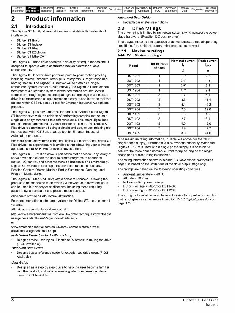
2.2.1 Maximum ratingsTable 2-1 Maximum ratings
*The maximum rating information, in Table 2-1 above, for the 200 V single phase supply, illustrates a 200 % overload capability. When the Digitax ST 120x is used with a single phase supply it is possible to achieve the three phase nominal current rating as long as the single phase peak current rating is observed. The rating information shown in section 2.3 Drive model numbers on page 9 is based on the limitations of the drive output stage only.The ratings are based on the following operating conditions:• Ambient temperature = 40 °C• Altitude = 1000 m• Not exceeding power ratings• DC bus voltage = 565 V for DST140X• DC bus voltage = 325 V for DST120XThe sizing tool should be used to select a drive for a profile or condition that is not given as an example in section 13.1.2 Typical pulse duty on page 173.
Model No of input phases
Nominal current In
Peak currentIMAX
A ADST1201 1 1.1* 2.2DST1202 1 2.4* 4.8DST1203 1 2.9* 5.8DST1204 1 4.7* 9.4DST1201 3 1.7 5.1DST1202 3 3.8 11.4DST1203 3 5.4 16.2DST1204 3 7.6 22.8DST1401 3 1.5 4.5DST1402 3 2.7 8.1DST1403 3 4.0 12.0DST1404 3 5.9 17.7DST1405 3 8.0 24.0
8 Digitax ST User Guide Issue: 5
Safety Information
Product information
Mechanical installation
Electrical installation
Getting started
Basic parameters
Running the motor Optimization EtherCAT
interfaceSMARTCARD
OperationOnboard
PLCAdvanced
parametersTechnical
Data Diagnostics UL listing information
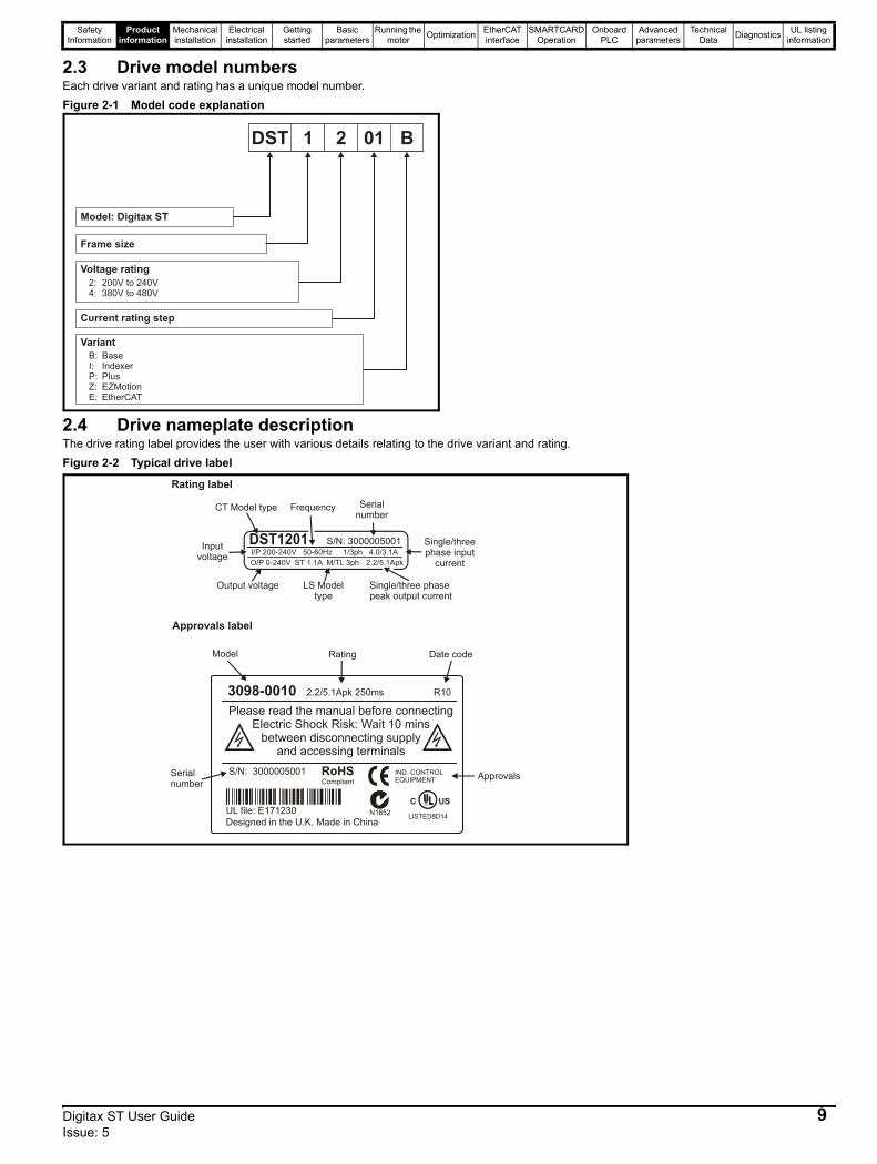
2.3 Drive model numbersEach drive variant and rating has a unique model number.Figure 2-1 Model code explanation
2.4 Drive nameplate descriptionThe drive rating label provides the user with various details relating to the drive variant and rating. Figure 2-2 Typical drive label
Model: Digitax ST
Frame size
Voltage rating
2:4:
200V to 240V380V to 480V
Current rating step
Variant
DST 1 2 01 B
B:I:P:Z:E:
BaseIndexerPlusEZMotionEtherCAT
Model
3098-0010 2.2/5.1Apk 250ms
S/N: 3000005001Serial number
Rating
Please read the manual before connectingElectric Shock Risk: Wait 10 mins
between disconnecting supply and accessing terminals
UL file: E171230
Approvals
Approvals label
Designed in the U.K. Made in China
IND. CONTROLEQUIPMENT
R
RoHSCompliant
I/P 200-240V 50-60Hz 1/3ph 4.0/3.1AO/P 0-240V 2.2/5.1Apk
Inputvoltage
CT Model type Serialnumber
Single/three phasepeak output current
Output voltage
ST 1.1A M/TL 3ph
Rating label
S/N: 3000005001 Single/three phase input
current
Frequency
LS Modeltype
C US
8
R10
Date code
N1652
Digitax ST User Guide 9Issue: 5

Safety Information
Product information
Mechanical installation
Electrical installation
Getting started
Basic parameters
Running the motor Optimization EtherCAT
interfaceSMARTCARD
OperationOnboard
PLCAdvanced
parametersTechnical
Data Diagnostics UL listing information
2.5 Features of the driveFigure 2-3 Features of the drive
* The Marker Tag (as shown in Figure 2-3 above), is where markers can be placed to identify a particular drive which can prove beneficial where several Digitax ST drives are located in the same panel.** A drive reset can be performed even when a keypad is not installed, by pressing the recessed reset button.
If the embedded interface is removed, the warranty for the drive will be void.
The drive is supplied with a SMARTCARD installed. Do not remove until after first power-up, as defaults are stored on the SMARTCARD.
SolutionsModuleslot 2cover
SolutionsModuleslot 1 cover
Bufferedencoder output
Encoder Inconnection
Motor connections
Line togroundvaristorscrew
AC supply
48V connection(for low voltageDC operation)
Brakingresistorconnections
SMARTCARDslot
Serial portconnector
Controlterminals
Relayterminal
Keypadconnection
EMC bracketGroundscrew
EMC bracket
Groundscrew
Status LEDMarker taglocation*
InternalEMCfilter screw
Ratinglabel
Approvalslabel
Brakeresistor slot
Resetbutton**
Fan
Control cablestrain relief
Productidentifier
NOTE
NOTE
Be aware of possible live terminals when inserting the SMARTCARD.
WARNING
Static precautions must be taken when removing the Solutions Module slot covers.
CAUTION
10 Digitax ST User Guide Issue: 5

Safety Information
Product information
Mechanical installation
Electrical installation
Getting started
Basic parameters
Running the motor Optimization EtherCAT
interfaceSMARTCARD
OperationOnboard
PLCAdvanced
parametersTechnical
Data Diagnostics UL listing information
2.6 OptionsFigure 2-4 Options available with Digitax ST
* A SMARTCARD is provided as standard. For further information refer to Chapter 10 SMARTCARD Operation on page 101.All Solutions Modules are color-coded in order to make identification easy. The following table shows the color-code key and gives further details on their function.
Table 2-2 Solutions Module identification
SM-Keypad PlusSMARTCARD*
DST Keypad
CT Commscable
External footprint/bookcase EMCfilter
Internal brakingresistor
Groundingbracket
15-way D-type
converter
I/O ExpansionApplications
AutomationFieldbus
Feedback
Slot 2
Slot 1
*
Type Solutions Module Color Name Further Details
Feedback
Light Green SM-Universal Encoder Plus
Universal Feedback interfaceFeedback interface for the following devices:
Light Blue SM-ResolverResolver interfaceFeedback interface for resolvers.Simulated quadrature encoder outputs
Brown SM-Encoder Plus
Incremental encoder interfaceFeedback interface for incremental encoders without commutation signals.No simulated encoder outputs available
Inputs Outputs• Incremental encoders • Quadrature• SinCos encoders • Frequency and direction• SSI encoders • SSI simulated outputs• EnDat encoders
Digitax ST User Guide 11Issue: 5
Safety Information
Product information
Mechanical installation
Electrical installation
Getting started
Basic parameters
Running the motor Optimization EtherCAT
interfaceSMARTCARD
OperationOnboard
PLCAdvanced
parametersTechnical
Data Diagnostics UL listing information
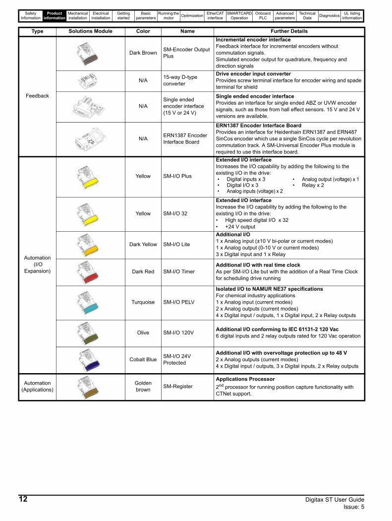
Feedback
Dark Brown SM-Encoder Output Plus
Incremental encoder interfaceFeedback interface for incremental encoders without commutation signals.Simulated encoder output for quadrature, frequency and direction signals
N/A 15-way D-type converter
Drive encoder input converterProvides screw terminal interface for encoder wiring and spade terminal for shield
N/ASingle ended encoder interface (15 V or 24 V)
Single ended encoder interfaceProvides an interface for single ended ABZ or UVW encoder signals, such as those from hall effect sensors. 15 V and 24 V versions are available.
N/A ERN1387 Encoder Interface Board
ERN1387 Encoder Interface BoardProvides an interface for Heidenhain ERN1387 and ERN487 SinCos encoder which use a single SinCos cycle per revolution commutation track. A SM-Universal Encoder Plus module is required to use this interface board.
Automation (I/O
Expansion)
Yellow SM-I/O Plus
Extended I/O interfaceIncreases the I/O capability by adding the following to the existing I/O in the drive:
Yellow SM-I/O 32
Extended I/O interfaceIncrease the I/O capability by adding the following to the existing I/O in the drive:• High speed digital I/O x 32• +24 V output
Dark Yellow SM-I/O Lite
Additional I/O1 x Analog input (±10 V bi-polar or current modes)1 x Analog output (0-10 V or current modes)3 x Digital input and 1 x Relay
Dark Red SM-I/O TimerAdditional I/O with real time clockAs per SM-I/O Lite but with the addition of a Real Time Clock for scheduling drive running
Turquoise SM-I/O PELV
Isolated I/O to NAMUR NE37 specificationsFor chemical industry applications1 x Analog input (current modes)2 x Analog outputs (current modes)4 x Digital input / outputs, 1 x Digital input, 2 x Relay outputs
Olive SM-I/O 120V Additional I/O conforming to IEC 61131-2 120 Vac6 digital inputs and 2 relay outputs rated for 120 Vac operation
Cobalt Blue SM-I/O 24V Protected
Additional I/O with overvoltage protection up to 48 V2 x Analog outputs (current modes)4 x Digital input / outputs, 3 x Digital inputs, 2 x Relay outputs
Automation(Applications)
Golden brown SM-Register
Applications Processor2nd processor for running position capture functionality with CTNet support.
Type Solutions Module Color Name Further Details
• Digital inputs x 3 • Analog output (voltage) x 1• Digital I/O x 3 • Relay x 2• Analog inputs (voltage) x 2
12 Digitax ST User Guide Issue: 5
Safety Information
Product information
Mechanical installation
Electrical installation
Getting started
Basic parameters
Running the motor Optimization EtherCAT
interfaceSMARTCARD
OperationOnboard
PLCAdvanced
parametersTechnical
Data Diagnostics UL listing information
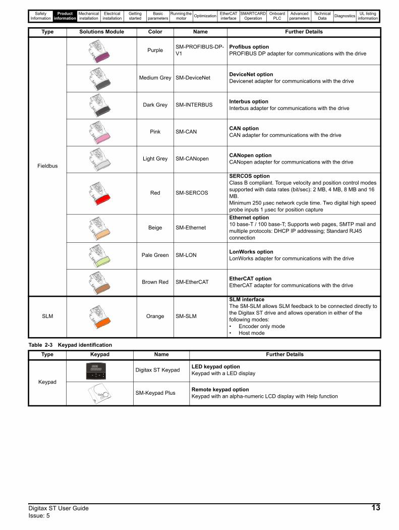
Table 2-3 Keypad identification
Fieldbus
Purple SM-PROFIBUS-DP-V1
Profibus optionPROFIBUS DP adapter for communications with the drive
Medium Grey SM-DeviceNet DeviceNet optionDevicenet adapter for communications with the drive
Dark Grey SM-INTERBUS Interbus optionInterbus adapter for communications with the drive
Pink SM-CAN CAN optionCAN adapter for communications with the drive
Light Grey SM-CANopen CANopen optionCANopen adapter for communications with the drive
Red SM-SERCOS
SERCOS optionClass B compliant. Torque velocity and position control modes supported with data rates (bit/sec): 2 MB, 4 MB, 8 MB and 16 MB.Minimum 250 μsec network cycle time. Two digital high speed probe inputs 1 μsec for position capture
Beige SM-Ethernet
Ethernet option10 base-T / 100 base-T; Supports web pages, SMTP mail and multiple protocols: DHCP IP addressing; Standard RJ45 connection
Pale Green SM-LON LonWorks optionLonWorks adapter for communications with the drive
Brown Red SM-EtherCAT EtherCAT optionEtherCAT adapter for communications with the drive
SLM Orange SM-SLM
SLM interfaceThe SM-SLM allows SLM feedback to be connected directly to the Digitax ST drive and allows operation in either of the following modes:• Encoder only mode• Host mode
Type Solutions Module Color Name Further Details
Type Keypad Name Further Details
Keypad
Digitax ST Keypad LED keypad optionKeypad with a LED display
SM-Keypad Plus Remote keypad optionKeypad with an alpha-numeric LCD display with Help function
Digitax ST User Guide 13Issue: 5
Safety Information
Product information
Mechanical installation
Electrical installation
Getting started
Basic parameters
Running the motor Optimization EtherCAT
interfaceSMARTCARD
OperationOnboard
PLCAdvanced
parametersTechnical
Data Diagnostics UL listing information
Table 2-4 Other options
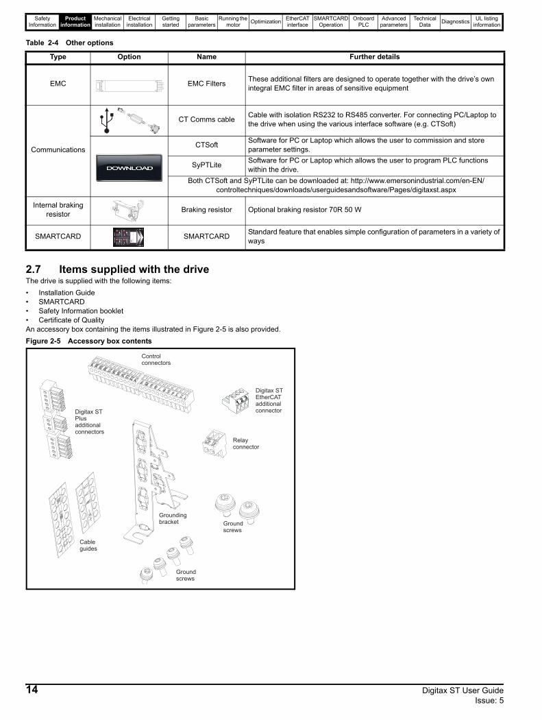
2.7 Items supplied with the driveThe drive is supplied with the following items: • Installation Guide• SMARTCARD• Safety Information booklet• Certificate of QualityAn accessory box containing the items illustrated in Figure 2-5 is also provided.Figure 2-5 Accessory box contents
Type Option Name Further details
EMC EMC Filters These additional filters are designed to operate together with the drive’s own integral EMC filter in areas of sensitive equipment
Communications
CT Comms cable Cable with isolation RS232 to RS485 converter. For connecting PC/Laptop to the drive when using the various interface software (e.g. CTSoft)
CTSoft Software for PC or Laptop which allows the user to commission and store parameter settings.
SyPTLite Software for PC or Laptop which allows the user to program PLC functions within the drive.
Both CTSoft and SyPTLite can be downloaded at: http://www.emersonindustrial.com/en-EN/controltechniques/downloads/userguidesandsoftware/Pages/digitaxst.aspx
Internal braking resistor Braking resistor Optional braking resistor 70R 50 W
SMARTCARD SMARTCARD Standard feature that enables simple configuration of parameters in a variety of ways
Controlconnectors
Relayconnector
Groundscrews
Cableguides
Groundingbracket
Groundscrews
Digitax STPlusadditionalconnectors
12
3
Digitax STEtherCATadditionalconnector
14 Digitax ST User Guide Issue: 5
Safety Information
Product information
Mechanical installation
Electrical installation
Getting started
Basic parameters
Running the motor Optimization EtherCAT
interfaceSMARTCARD
OperationOnboard
PLCAdvanced
parametersTechnical
Data Diagnostics UL listing information
3 Mechanical installationThis chapter describes how to use all mechanical details to install the drive. The drive is intended to be installed in an enclosure. Key features of this chapter include:• Through-hole mounting• IP54 as standard or through-panel mounting• Enclosure sizing and layout• Solutions Module installing• Terminal location and torque settings
3.1 Safety information
3.2 Planning the installationThe following considerations must be made when planning the installation:
3.2.1 AccessAccess must be restricted to authorized personnel only. Safety regulations which apply at the place of use must be complied with.
3.2.2 Environmental protectionThe drive must be protected from:• moisture, including dripping water or spraying water and
condensation. An anti-condensation heater may be required, which must be switched off when the drive is running.
• contamination with electrically conductive material• contamination with any form of dust which may restrict the fan, or
impair airflow over various components• temperature beyond the specified operating and storage ranges
• corrosive gasses
During installation it is recommended that the vents on the drive are covered to prevent debris (e.g. wire off-cuts) from entering the drive.
3.2.3 CoolingThe heat produced by the drive must be removed without its specified operating temperature being exceeded. Note that a sealed enclosure gives much reduced cooling compared with a ventilated one, and may need to be larger and/or use internal air circulating fans.
3.2.4 Electrical safetyThe installation must be safe under normal and fault conditions. Electrical installation instructions are given in Chapter 4 Electrical installation on page 21.
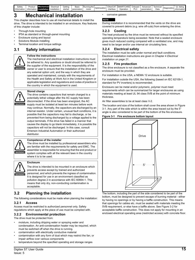
3.2.5 Fire protectionThe drive enclosure is not classified as a fire enclosure. A separate fire enclosure must be provided.For installation in the USA, a NEMA 12 enclosure is suitable.For installation outside the USA, the following (based on IEC 62109-1, standard for PV inverters) is recommended.Enclosure can be metal and/or polymeric, polymer must meet requirements which can be summarized for larger enclosures as using materials meeting at least UL 94 class 5VB at the point of minimum thickness.Air filter assemblies to be at least class V-2.The location and size of the bottom shall cover the area shown in Figure 3-1. Any part of the side which is within the area traced out by the 5° angle is also considered to be part of the bottom of the fire enclosure.Figure 3-1 Fire enclosure bottom layout
The bottom, including the part of the side considered to be part of the bottom, must be designed to prevent escape of burning material - either by having no openings or by having a baffle construction. This means that openings for cables etc. must be sealed with materials meeting the 5VB requirement, or else have a baffle above. See Figure 3-2 for acceptable baffle construction. This does not apply for mounting in an enclosed electrical operating area (restricted access) with concrete floor.
Follow the instructionsThe mechanical and electrical installation instructions must be adhered to. Any questions or doubt should be referred to the supplier of the equipment. It is the responsibility of the owner or user to ensure that the installation of the drive and any external option unit, and the way in which they are operated and maintained, comply with the requirements of the Health and Safety at Work Act in the United Kingdom or applicable legislation and regulations and codes of practice in the country in which the equipment is used.
Stored chargeThe drive contains capacitors that remain charged to a potentially lethal voltage after the AC supply has been disconnected. If the drive has been energized, the AC supply must be isolated at least ten minutes before work may continue. Normally, the capacitors are discharged by an internal resistor. Under certain, unusual fault conditions, it is possible that the capacitors may fail to discharge, or be prevented from being discharged by a voltage applied to the output terminals. If the drive has failed in a manner that causes the display to go blank immediately, it is possible the capacitors will not be discharged. In this case, consult Emerson Industrial Automation or their authorized distributor.
Competence of the installerThe drive must be installed by professional assemblers who are familiar with the requirements for safety and EMC. The assembler is responsible for ensuring that the end product or system complies with all the relevant laws in the country where it is to be used.
EnclosureThe drive is intended to be mounted in an enclosure which prevents access except by trained and authorized personnel, and which prevents the ingress of contamination. It is designed for use in an environment classified as pollution degree 2 in accordance with IEC 60664-1. This means that only dry, non-conducting contamination is acceptable.
WARNING
WARNING
WARNING
WARNING
NOTE
Drive
5o
Digitax ST User Guide 15Issue: 5
Safety Information
Product information
Mechanical installation
Electrical installation
Getting started
Basic parameters
Running the motor Optimization EtherCAT
interfaceSMARTCARD
OperationOnboard
PLCAdvanced
parametersTechnical
Data Diagnostics UL listing information
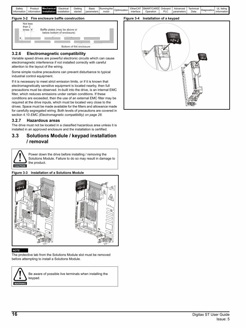
Figure 3-2 Fire enclosure baffle construction
3.2.6 Electromagnetic compatibilityVariable speed drives are powerful electronic circuits which can cause electromagnetic interference if not installed correctly with careful attention to the layout of the wiring.Some simple routine precautions can prevent disturbance to typical industrial control equipment.If it is necessary to meet strict emission limits, or if it is known that electromagnetically sensitive equipment is located nearby, then full precautions must be observed. In-built into the drive, is an internal EMC filter, which reduces emissions under certain conditions. If these conditions are exceeded, then the use of an external EMC filter may be required at the drive inputs, which must be located very close to the drives. Space must be made available for the filters and allowance made for carefully segregated wiring. Both levels of precautions are covered in section 4.10 EMC (Electromagnetic compatibility) on page 28.
3.2.7 Hazardous areasThe drive must not be located in a classified hazardous area unless it is installed in an approved enclosure and the installation is certified.
3.3 Solutions Module / keypad installation / removal
Figure 3-3 Installation of a Solutions Module
The protective tab from the Solutions Module slot must be removed before attempting to install a Solutions Module.
Figure 3-4 Installation of a keypad
Power down the drive before installing / removing the Solutions Module. Failure to do so may result in damage to the product.
Be aware of possible live terminals when installing the keypad.
N o t l e s st h a n 2 X B a f f l e p l a t e s ( m a y b e
a b o v e o r b e l o w b o t t o mo f e n c l o s u r e )
X
B o t t o m o f f i r ee n c l o s u r e
Not lessthan 2 times ‘X’ Baffle plates (may be above or
below bottom of enclosure)
Bottom of fire enclosure
X
CAUTION
NOTE
WARNING
16 Digitax ST User Guide Issue: 5
Safety Information
Product information
Mechanical installation
Electrical installation
Getting started
Basic parameters
Running the motor Optimization EtherCAT
interfaceSMARTCARD
OperationOnboard
PLCAdvanced
parametersTechnical
Data Diagnostics UL listing information
3.4 Drive dimensions
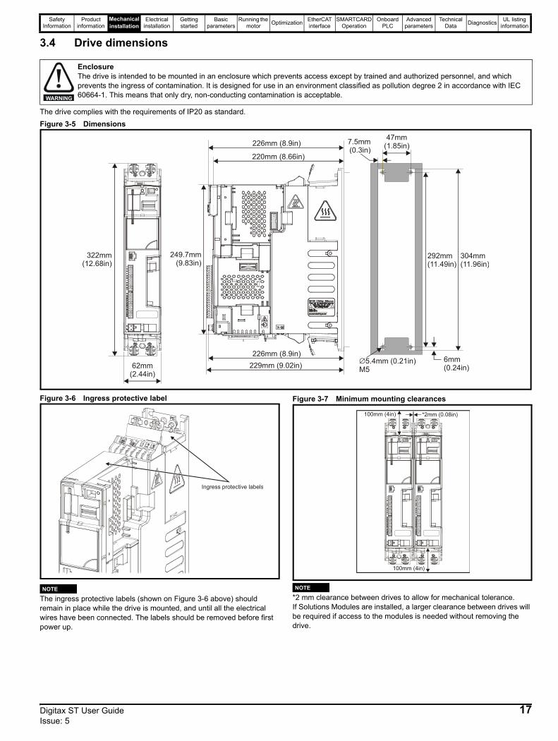
The drive complies with the requirements of IP20 as standard.Figure 3-5 Dimensions
Figure 3-6 Ingress protective label
The ingress protective labels (shown on Figure 3-6 above) should remain in place while the drive is mounted, and until all the electrical wires have been connected. The labels should be removed before first power up.
Figure 3-7 Minimum mounting clearances
*2 mm clearance between drives to allow for mechanical tolerance.If Solutions Modules are installed, a larger clearance between drives will be required if access to the modules is needed without removing the drive.
EnclosureThe drive is intended to be mounted in an enclosure which prevents access except by trained and authorized personnel, and which prevents the ingress of contamination. It is designed for use in an environment classified as pollution degree 2 in accordance with IEC 60664-1. This means that only dry, non-conducting contamination is acceptable.WARNING
62mm(2.44in)
249.7mm(9.83in)
220mm (8.66in)
47mm(1.85in)7.5mm
(0.3in)
304mm(11.96in)
292mm(11.49in)
6mm(0.24in)
∅5.4mm (0.21in)M5
322mm(12.68in)
226mm (8.9in)
226mm (8.9in)229mm (9.02in)
Ingress protective labels
NOTE
100mm (4in)
100mm (4in) *2mm (0.08in)
NOTE
Digitax ST User Guide 17Issue: 5
Safety Information
Product information
Mechanical installation
Electrical installation
Getting started
Basic parameters
Running the motor Optimization EtherCAT
interfaceSMARTCARD
OperationOnboard
PLCAdvanced
parametersTechnical
Data Diagnostics UL listing information
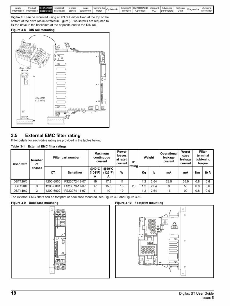
Digitax ST can be mounted using a DIN rail, either fixed at the top or the bottom of the drive (as illustrated in Figure ). Two screws are required to fix the drive to the backplate at the opposite end to the DIN rail. Figure 3-8 DIN rail mounting
3.5 External EMC filter ratingFilter details for each drive rating are provided in the tables below.
Table 3-1 External EMC filter ratings
The external EMC filters can be footprint or bookcase mounted, see Figure 3-9 and Figure 3-10.
Figure 3-9 Bookcase mounting Figure 3-10 Footprint mounting
47mm (1.85in)
312.7mm(12.31in)
Used withNumber
of phases
Filter part numberMaximum
continuous current
Power losses at rated current IP
rating
WeightOperational
leakage current
Worst case
leakage current
Filter terminal
tightening torque
CT Schaffner@40°C(104°F)
A
@50°C(122°F)
AW Kg lb mA mA Nm lb ft
DST120X 1 4200-6000 FS23072-19-07 19 17.3 1120
1.2 2.64 29.5 56.9 0.8 0.6DST120X 3 4200-6001 FS23073-17-07 17 15.5 13 1.2 2.64 8 50 0.8 0.6DST140X 3 4200-6002 FS23074-11-07 11 10 10 1.2 2.64 16 90 0.8 0.6
18 Digitax ST User Guide Issue: 5
Safety Information
Product information
Mechanical installation
Electrical installation
Getting started
Basic parameters
Running the motor Optimization EtherCAT
interfaceSMARTCARD
OperationOnboard
PLCAdvanced
parametersTechnical
Data Diagnostics UL listing information
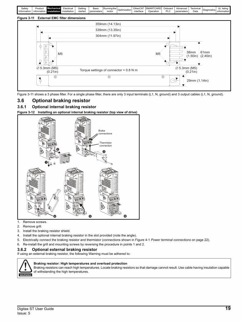
Figure 3-11 External EMC filter dimensions
Figure 3-11 shows a 3 phase filter. For a single phase filter, there are only 3 input terminals (L1, N, ground) and 3 output cables (L1, N, ground).
3.6 Optional braking resistor3.6.1 Optional internal braking resistorFigure 3-12 Installing an optional internal braking resistor (top view of drive)
1. Remove screws.2. Remove grill.3. Install the braking resistor shield.4. Install the optional internal braking resistor in the slot provided (note the angle).5. Electrically connect the braking resistor and thermistor (connections shown in Figure 4-1 Power terminal connections on page 22).6. Re-install the grill and mounting screws by reversing the procedure in points 1 and 2.
3.6.2 Optional external braking resistorIf using an external braking resistor, the following Warning must be adhered to:
Braking resistor: High temperatures and overload protectionBraking resistors can reach high temperatures. Locate braking resistors so that damage cannot result. Use cable having insulation capable of withstanding the high temperatures.
29mm (1.14in)
359mm (14.13in)
339mm (13.35in)
304mm (11.97in)
38mm(1.50in)
61mm(2.40in)M5 M5
Torque settings of connector = 0.8 N m∅ 5.3mm (M5)(0.21in)
∅ 5.3mm (M5)(0.21in)
4
2
1
Brakeconnections
Thermistorconnection
3
5 6
WARNING
Digitax ST User Guide 19Issue: 5
Safety Information
Product information
Mechanical installation
Electrical installation
Getting started
Basic parameters
Running the motor Optimization EtherCAT
interfaceSMARTCARD
OperationOnboard
PLCAdvanced
parametersTechnical
Data Diagnostics UL listing information
3.7 Terminal torque settingsTable 3-2 Torque settings
*Torque tolerance = 10 %
Table 3-3 Plug-in terminal block maximum cable sizes
3.8 Routine maintenance The drive should be installed in a cool, clean, well ventilated location. Contact of moisture and dust with the drive should be prevented.Regular checks of the following should be carried out to ensure drive / installation reliability are maximized:
Terminals Torque setting*Power terminals 1.0 N m (12.1 lb in)Control terminals 0.2 N m (1.7 lb in)
Status relay terminals 0.5 N m (4.5 lb in)Ground terminals 4 N m (35 lb in)
Small ground terminal screws 2 N m (17.7 lb in)
Model size Terminal block description Max cable size
All 11 way control connectors 1.5 mm2 (16 AWG)All 2 way relay connector 2.5 mm2 (12 AWG)
Environment
Ambient temperature
Ensure the enclosure temperature remains at or below maximum specified
DustEnsure the drive remains dust free – check that the heatsink and drive fan are not gathering dust. The lifetime of the fan is reduced in dusty environments.
Moisture Ensure the drive enclosure shows no signs of condensation
Enclosure
Enclosure door filters Ensure filters are not blocked and that air is free to flow
Electrical
Screw connections Ensure all screw terminals remain tight
Crimp terminals
Ensure all crimp terminals remains tight – check for any discoloration which could indicate overheating
Cables Check all cables for signs of damage
20 Digitax ST User Guide Issue: 5
Safety Information
Product information
Mechanical installation
Electrical installation
Getting started
Basic parameters
Running the motor Optimization EtherCAT
interfaceSMARTCARD
OperationOnboard
PLCAdvanced
parametersTechnical
Data Diagnostics UL listing information
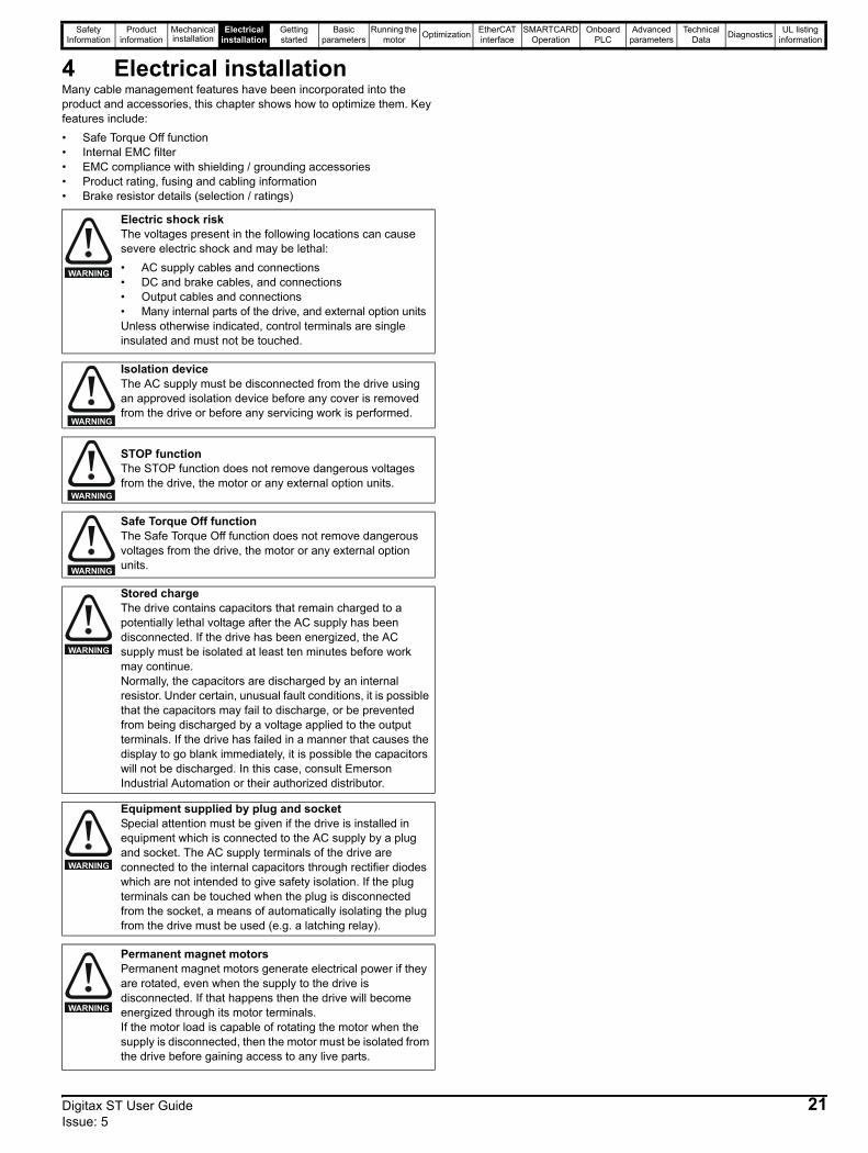
4 Electrical installationMany cable management features have been incorporated into the product and accessories, this chapter shows how to optimize them. Key features include:• Safe Torque Off function• Internal EMC filter• EMC compliance with shielding / grounding accessories• Product rating, fusing and cabling information• Brake resistor details (selection / ratings)
Electric shock riskThe voltages present in the following locations can cause severe electric shock and may be lethal:• AC supply cables and connections• DC and brake cables, and connections• Output cables and connections• Many internal parts of the drive, and external option unitsUnless otherwise indicated, control terminals are single insulated and must not be touched.
Isolation device The AC supply must be disconnected from the drive using an approved isolation device before any cover is removed from the drive or before any servicing work is performed.
STOP functionThe STOP function does not remove dangerous voltages from the drive, the motor or any external option units.
Safe Torque Off functionThe Safe Torque Off function does not remove dangerous voltages from the drive, the motor or any external option units.
Stored chargeThe drive contains capacitors that remain charged to a potentially lethal voltage after the AC supply has been disconnected. If the drive has been energized, the AC supply must be isolated at least ten minutes before work may continue.Normally, the capacitors are discharged by an internal resistor. Under certain, unusual fault conditions, it is possible that the capacitors may fail to discharge, or be prevented from being discharged by a voltage applied to the output terminals. If the drive has failed in a manner that causes the display to go blank immediately, it is possible the capacitors will not be discharged. In this case, consult Emerson Industrial Automation or their authorized distributor.
Equipment supplied by plug and socketSpecial attention must be given if the drive is installed in equipment which is connected to the AC supply by a plug and socket. The AC supply terminals of the drive are connected to the internal capacitors through rectifier diodes which are not intended to give safety isolation. If the plug terminals can be touched when the plug is disconnected from the socket, a means of automatically isolating the plug from the drive must be used (e.g. a latching relay).
Permanent magnet motorsPermanent magnet motors generate electrical power if they are rotated, even when the supply to the drive is disconnected. If that happens then the drive will become energized through its motor terminals.If the motor load is capable of rotating the motor when the supply is disconnected, then the motor must be isolated from the drive before gaining access to any live parts.
WARNING
WARNING
WARNING
WARNING
WARNING
WARNING
WARNING
Digitax ST User Guide 21Issue: 5
Safety Information
Product information
Mechanical installation
Electrical installation
Getting started
Basic parameters
Running the motor Optimization EtherCAT
interfaceSMARTCARD
OperationOnboard
PLCAdvanced
parametersTechnical
Data Diagnostics UL listing information
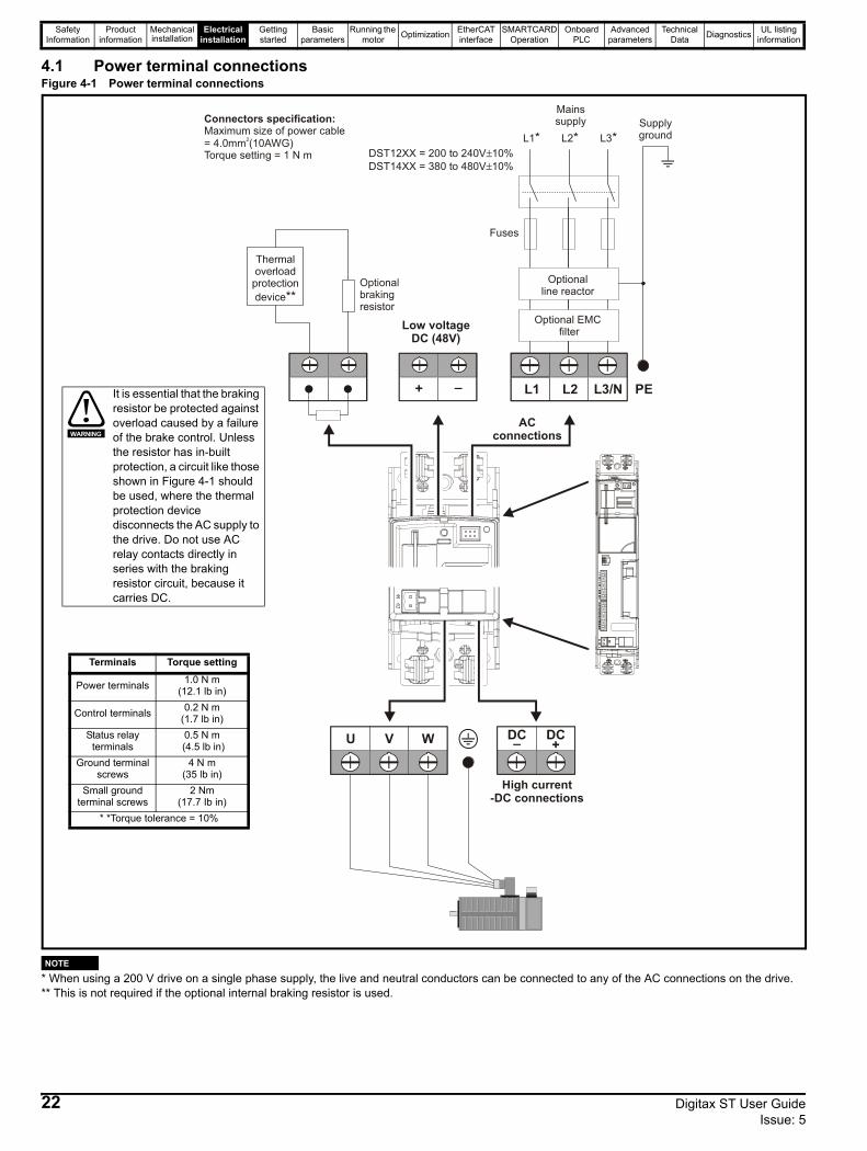
4.1 Power terminal connectionsFigure 4-1 Power terminal connections
* When using a 200 V drive on a single phase supply, the live and neutral conductors can be connected to any of the AC connections on the drive.** This is not required if the optional internal braking resistor is used.
L1* L2*
L2L1 L3/N
U V W
Optional EMC filter
Optionalline reactor
Fuses
L3*
Mainssupply Supply
ground
ACconnections
_ +DC DC
High current-DC connections
+ _
Low voltageDC (48V)
DST12XX = 200 to 240V 10%DST14XX = 380 to 480V 10%
±±
Connectors specification:Maximum size of power cable= 4.0mm (10AWG)Torque setting = 1 N m
2
PEIt is essential that the braking resistor be protected against overload caused by a failure of the brake control. Unless the resistor has in-built protection, a circuit like those shown in Figure 4-1 should be used, where the thermal protection device disconnects the AC supply to the drive. Do not use AC relay contacts directly in series with the braking resistor circuit, because it carries DC.
WARNING
Terminals Torque setting
Power terminals 1.0 N m (12.1 lb in)
Control terminals 0.2 N m (1.7 lb in)
Status relay terminals
0.5 N m (4.5 lb in)
Ground terminalscrews
4 N m (35 lb in)
Small ground terminal screws
2 Nm(17.7 Ib in)
* *Torque tolerance = 10%
NOTE
22 Digitax ST User Guide Issue: 5
Safety Information
Product information
Mechanical installation
Electrical installation
Getting started
Basic parameters
Running the motor Optimization EtherCAT
interfaceSMARTCARD
OperationOnboard
PLCAdvanced
parametersTechnical
Data Diagnostics UL listing information
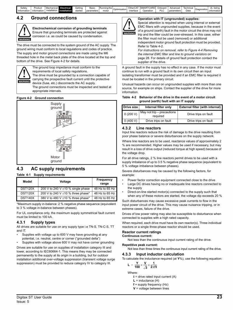
4.2 Ground connections
The drive must be connected to the system ground of the AC supply. The ground wiring must conform to local regulations and codes of practice.The supply and motor ground connections are made using the M6 threaded hole in the metal back plate of the drive located at the top and bottom of the drive. See Figure 4-2 for details.
Figure 4-2 Ground connection
4.3 AC supply requirementsTable 4-1 Supply requirements
*Maximum supply in-balance: 2 % negative phase sequence (equivalent to 3 % voltage in-balance between phases).For UL compliance only, the maximum supply symmetrical fault current must be limited to 100 kA.
4.3.1 Supply typesAll drives are suitable for use on any supply type i.e TN-S, TN-C-S, TT and IT.• Supplies with voltage up to 600 V may have grounding at any
potential, i.e. neutral, centre or corner (“grounded delta”)• Supplies with voltage above 600 V may not have corner groundingDrives are suitable for use on supplies of installation category III and lower, according to IEC60664-1. This means they may be connected permanently to the supply at its origin in a building, but for outdoor installation additional over-voltage suppression (transient voltage surge suppression) must be provided to reduce category IV to category III.
A ground fault in the supply has no effect in any case. If the motor must continue to run with a ground fault in its own circuit then an input isolating transformer must be provided and if an EMC filter is required it must be located in the primary circuit.Unusual hazards can occur on ungrounded supplies with more than one source, for example on ships. Contact the supplier of the drive for more information.Table 4-2 Behavior of the drive in the event of a motor circuit
ground (earth) fault with an IT supply
4.3.2 Line reactorsInput line reactors reduce the risk of damage to the drive resulting from poor phase balance or severe disturbances on the supply network.Where line reactors are to be used, reactance values of approximately 2 % are recommended. Higher values may be used if necessary, but may result in a loss of drive output (reduced torque at high speed) because of the voltage drop.For all drive ratings, 2 % line reactors permit drives to be used with a supply imbalance of up to 3.5 % negative phase sequence (equivalent to 5 % voltage imbalance between phases).Severe disturbances may be caused by the following factors, for example:• Power factor correction equipment connected close to the drive• Large DC drives having no or inadequate line reactors connected to
the supply• Direct-on-line started motor(s) connected to the supply such that
when any of these motors are started, the voltage dip exceeds 20 %Such disturbances may cause excessive peak currents to flow in the input power circuit of the drive. This may cause nuisance tripping, or in extreme cases, failure of the drive.Drives of low power rating may also be susceptible to disturbance when connected to supplies with a high rated capacity.When required, each drive must have its own reactor(s). Three individual reactors or a single three-phase reactor should be used.
Reactor current ratingsContinuous current:
Not less than the continuous input current rating of the drive.Repetitive peak current:
Not less than three times the continuous input current rating of the drive.
4.3.3 Input inductor calculationTo calculate the inductance required (at Y%), use the following equation:
Where:I = drive rated input current (A)L = inductance (H)f = supply frequency (Hz)V = voltage between lines
Electrochemical corrosion of grounding terminalsEnsure that grounding terminals are protected against corrosion i.e. as could be caused by condensation.
The ground loop impedance must conform to the requirements of local safety regulations. The drive must be grounded by a connection capable of carrying the prospective fault current until the protective device (fuse, etc.) disconnects the AC supply. The ground connections must be inspected and tested at appropriate intervals.
Model Voltage Frequency range
DST120X 200 V to 240 V ±10 % single phase 48 Hz to 65 HzDST120X 200 V to 240 V ±10 % three phase* 48 Hz to 65 HzDST140X 380 V to 480 V ±10 % three phase* 48 Hz to 65 Hz
WARNING
WARNING
Supplyground
Motorground
Operation with IT (ungrounded) supplies:Special attention is required when using internal or external EMC filters with ungrounded supplies, because in the event of a ground (earth) fault in the motor circuit the drive may not trip and the filter could be over-stressed. In this case, either the filter must not be used (removed) or additional independent motor ground fault protection must be provided. Refer to Table 4-2.For instructions on removal, refer to Figure 4-4 Removing the internal EMC filter and line to ground varistors on page 28. For details of ground fault protection contact the supplier of the drive.
Drive size Internal filter only External filter (with internal)
0 (200 V) May not trip – precautions required Drive trips on fault
0 (400 V) Drive trips on fault Drive trips on fault
WARNING
L Y100---------- V
3-------× 1
2πfI------------×=
Digitax ST User Guide 23Issue: 5

Safety Information
Product information
Mechanical installation
Electrical installation
Getting started
Basic parameters
Running the motor Optimization EtherCAT
interfaceSMARTCARD
OperationOnboard
PLCAdvanced
parametersTechnical
Data Diagnostics UL listing information
4.4 DC bus design4.4.1 DC bus designParallel connectionsThe power limit of the rectifier must be adhered to for all combinations of drives in parallel. In addition to this If the total rated bus power required exceeds the capability of 1 x Digitax ST rectifier then two or more Digitax ST's can be connected with the AC & DC in parallel. If the AC supply is connected to more than one drive in a parallel DC bus application, balancing of the current in the input stage of each drive must be considered.Using DC bus chokes makes the current in the rectifier diodes of each drive the same, so providing a solution to sharing. There are many possible combinations for paralleling drives through the DC bus connections. Table 4-3 gives details of the internal capacitance for each drive and the additional capacitance which can be powered from the drive. The capacitance must incorporate its own soft-start circuit. All Digitax ST drives incorporate this feature.
Table 4-3 DC bus data
For additional details regarding DC bus paralleling please contact the supplier of the drive.
4.5 DC drive voltage levels4.5.1 Low voltage DC operationThe drive can be operated from low voltage DC supplies, nominally 24 Vdc (control) and 48 Vdc (power). The low voltage DC power operating mode is designed either, to allow for motor operation in an emergency back-up situation following failure of the AC supply, for example in robotic arm applications; or to limit the speed of a servo motor during set-up of equipment, for example a robot cell.
The working voltage range of the low voltage DC power supply is shown in Table 4-4.
Table 4-4 Low voltage DC levels
4.5.2 High voltage DC levelsTable 4-5 High voltage DC levels
* These are the absolute minimum DC voltages that the drive is capable of operating from. If the drive is not supplied with the minimum voltage, it will not reset following a UV trip at power-up.
4.5.3 Control 24 Vdc supplyThe 24 Vdc input has three main functions:• It can be used as a back-up power supply to keep the control circuits
of the drive powered up when the line power supply is removed. This allows any fieldbus modules or serial communications to continue to operate.
• It can be used to supplement the drive’s own internal 24 V when multiple SM-I/O Plus modules are being used and the current drawn by these modules is greater than the drive can supply. (If too much current is drawn from the drive, the drive will initiate a 'PS.24V' trip)
• It can be used to commission the drive when line power supply voltages are not available, as the display operates correctly. However, the drive will be in the UV trip state unless either line power supply is reapplied or low voltage DC operation is enabled, therefore diagnostics may not be possible. (Power down save parameters are not saved when using the 24 V back-up power supply input.)
The working voltage range of the 24 V power supply is shown in Table 4-6.Table 4-6 Control supply voltage levels
Minimum and maximum voltage values include ripple and noise. Ripple and noise values must not exceed 5 %.
DriveInternal DC bus
capacitance(μF)
Maximum additional DC bus capacitance which can
be connected(μF)
DST1201 440 1760DST1202 880 1320DST1203 880 1320DST1204 1320 880DST1401 220 660DST1402 220 660DST1403 220 660DST1404 220 660DST1405 220 660
With low voltage DC operation there is a reduction in thelevel of safety of the Safe Torque Off function. Thereexist certain unlikely faults which might permit the drive toproduce some limited motor torque, if the DC supply has itsnegative terminal connected to ground.See section 4.17 Safe Torque Off on page 42 for methods on preventing a loss of the safety function under these conditions.
Condition ValueMinimum continuous operating voltage 36 VMinimum start up voltage 40 VNominal continuous operating voltage 48 V to 72 VMaximum braking IGBT turn on voltage 63 V to 95 VMaximum over voltage trip threshold 69 V to 104 V
NOTE
WARNING
ConditionDST120X DST140X
V VUndervoltage trip level 175 330
Undervoltage reset level* 215 425Overvoltage trip level 415 830
Braking level 390 780Maximum continuous voltage level for 15 s 400 800
Condition ValueMaximum continuous operating voltage 30.0 VMinimum continuous operating voltage 19.2 VNominal operating voltage 24.0 VMinimum start up voltage 21.6 VMaximum power supply requirement at 24 V 60 WRecommended fuse 3 A, 50 Vdc
24 Digitax ST User Guide Issue: 5
Safety Information
Product information
Mechanical installation
Electrical installation
Getting started
Basic parameters
Running the motor Optimization EtherCAT
interfaceSMARTCARD
OperationOnboard
PLCAdvanced
parametersTechnical
Data Diagnostics UL listing information
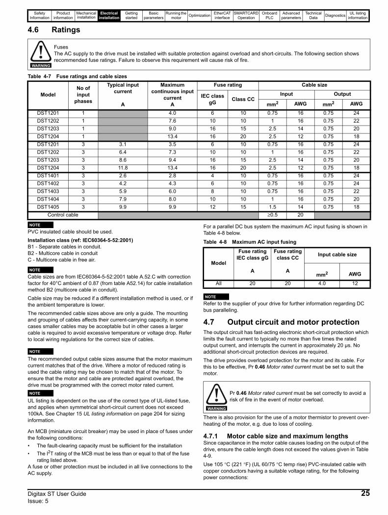
4.6 Ratings
Table 4-7 Fuse ratings and cable sizes
PVC insulated cable should be used.Installation class (ref: IEC60364-5-52:2001)B1 - Separate cables in conduit.B2 - Multicore cable in conduitC - Multicore cable in free air.
Cable sizes are from IEC60364-5-52:2001 table A.52.C with correction factor for 40°C ambient of 0.87 (from table A52.14) for cable installation method B2 (multicore cable in conduit).Cable size may be reduced if a different installation method is used, or if the ambient temperature is lower.The recommended cable sizes above are only a guide. The mounting and grouping of cables affects their current-carrying capacity, in some cases smaller cables may be acceptable but in other cases a larger cable is required to avoid excessive temperature or voltage drop. Refer to local wiring regulations for the correct size of cables.
NThe recommended output cable sizes assume that the motor maximum current matches that of the drive. Where a motor of reduced rating is used the cable rating may be chosen to match that of the motor. To ensure that the motor and cable are protected against overload, the drive must be programmed with the correct motor rated current.
NUL listing is dependent on the use of the correct type of UL-listed fuse, and applies when symmetrical short-circuit current does not exceed 100kA. See Chapter 15 UL listing information on page 204 for sizing information.
An MCB (miniature circuit breaker) may be used in place of fuses under the following conditions:• The fault-clearing capacity must be sufficient for the installation• The I2T rating of the MCB must be less than or equal to that of the fuse
rating listed above.A fuse or other protection must be included in all live connections to the AC supply.
For a parallel DC bus system the maximum AC input fusing is shown in Table 4-8 below.
Table 4-8 Maximum AC input fusing
Refer to the supplier of your drive for further information regarding DC bus paralleling.
4.7 Output circuit and motor protectionThe output circuit has fast-acting electronic short-circuit protection which limits the fault current to typically no more than five times the rated output current, and interrupts the current in approximately 20 µs. No additional short-circuit protection devices are required.The drive provides overload protection for the motor and its cable. For this to be effective, Pr 0.46 Motor rated current must be set to suit the motor.
There is also provision for the use of a motor thermistor to prevent over-heating of the motor, e.g. due to loss of cooling.
4.7.1 Motor cable size and maximum lengthsSince capacitance in the motor cable causes loading on the output of the drive, ensure the cable length does not exceed the values given in Table 4-9.Use 105 °C (221 °F) (UL 60/75 °C temp rise) PVC-insulated cable with copper conductors having a suitable voltage rating, for the following power connections:
FusesThe AC supply to the drive must be installed with suitable protection against overload and short-circuits. The following section shows recommended fuse ratings. Failure to observe this requirement will cause risk of fire.
WARNING
ModelNo of input
phases
Typical input current
A
Maximum continuous input
currentA
Fuse rating Cable size
IEC class gG Class CC
Input Output
mm2 AWG mm2 AWG
DST1201 1 4.0 6 10 0.75 16 0.75 24DST1202 1 7.6 10 10 1 16 0.75 22DST1203 1 9.0 16 15 2.5 14 0.75 20DST1204 1 13.4 16 20 2.5 12 0.75 18DST1201 3 3.1 3.5 6 10 0.75 16 0.75 24DST1202 3 6.4 7.3 10 10 1 16 0.75 22DST1203 3 8.6 9.4 16 15 2.5 14 0.75 20DST1204 3 11.8 13.4 16 20 2.5 12 0.75 18DST1401 3 2.6 2.8 4 10 0.75 16 0.75 24DST1402 3 4.2 4.3 6 10 0.75 16 0.75 24DST1403 3 5.9 6.0 8 10 0.75 16 0.75 22DST1404 3 7.9 8.0 10 10 1 16 0.75 20DST1405 3 9.9 9.9 12 15 1.5 14 0.75 18
Control cable ≥0.5 20
NOTE
NOTE
NOTE
NOTE
Model
Fuse ratingIEC class gG
Fuse ratingclass CC Input cable size
A Amm2 AWG
All 20 20 4.0 12
Pr 0.46 Motor rated current must be set correctly to avoid a risk of fire in the event of motor overload.
NOTE
WARNING
Digitax ST User Guide 25Issue: 5
Safety Information
Product information
Mechanical installation
Electrical installation
Getting started
Basic parameters
Running the motor Optimization EtherCAT
interfaceSMARTCARD
OperationOnboard
PLCAdvanced
parametersTechnical
Data Diagnostics UL listing information
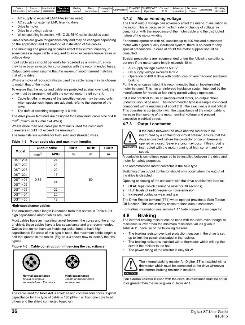
• AC supply to external EMC filter (when used)• AC supply (or external EMC filter) to drive• Drive to motor• Drive to braking resistor• When operating in ambient >45 °C UL 75 °C cable should be used.Cable sizes are given for guidance only and may be changed depending on the application and the method of installation of the cables.The mounting and grouping of cables affect their current capacity, in some cases a larger cable is required to avoid excessive temperature or voltage drop.Input cable sizes should generally be regarded as a minimum, since they have been selected for co-ordination with the recommended fuses.Output cable sizes assume that the maximum motor current matches that of the drive.Where a motor of reduced rating is used the cable rating may be chosen to match that of the motor.To ensure that the motor and cable are protected against overload, the drive must be programmed with the correct motor rated current.• Cable lengths in excess of the specified values may be used only
when special techniques are adopted; refer to the supplier of the drive.
• The default switching frequency is 6 kHz.The drive power terminals are designed for a maximum cable size of 4.0 mm2 (minimum 0.2 mm / 24 AWG).Where more than one cable per terminal is used the combined diameters should not exceed the maximum. The terminals are suitable for both solid and stranded wires.
Table 4-9 Motor cable size and maximum lengths
High-capacitance cables The maximum cable length is reduced from that shown in Table 4-9 if high capacitance motor cables are used.Most cables have an insulating jacket between the cores and the armor or shield; these cables have a low capacitance and are recommended. Cables that do not have an insulating jacket tend to have high capacitance; if a cable of this type is used, the maximum cable length is half that quoted in the tables. (Figure 4-3 shows how to identify the two types).Figure 4-3 Cable construction influencing the capacitance
The cable used for Table 4-9 is shielded and contains four cores. Typical capacitance for this type of cable is 130 pF/m (i.e. from one core to all others and the shield connected together).
4.7.2 Motor winding voltageThe PWM output voltage can adversely affect the inter-turn insulation in the motor. This is because of the high rate of change of voltage, in conjunction with the impedance of the motor cable and the distributed nature of the motor winding.For normal operation with AC supplies up to 500 Vac and a standard motor with a good quality insulation system, there is no need for any special precautions. In case of doubt the motor supplier should be consulted.Special precautions are recommended under the following conditions, but only if the motor cable length exceeds 10 m:• AC supply voltage exceeds 500 V• DC supply voltage exceeds 670 V• Operation of 400 V drive with continuous or very frequent sustained
brakingFor the other cases listed, it is recommended that an inverter-rated motor be used. This has a reinforced insulation system intended by the manufacturer for repetitive fast-rising pulsed voltage operation. If it is not practical to use an inverter-rated motor, an output choke (inductor) should be used. The recommended type is a simple iron-cored component with a reactance of about 2 %. The exact value is not critical. This operates in conjunction with the capacitance of the motor cable to increase the rise-time of the motor terminal voltage and prevent excessive electrical stress.
4.7.3 Output contactor
A contactor is sometimes required to be installed between the drive and motor for safety purposes. The recommended motor contactor is the AC3 type.Switching of an output contactor should only occur when the output of the drive is disabled.Opening or closing of the contactor with the drive enabled will lead to:1. OI.AC trips (which cannot be reset for 10 seconds)2. High levels of radio frequency noise emission3. Increased contactor wear and tearThe Drive Enable terminal (T31) when opened provides a Safe Torque Off function. This can in many cases replace output contactors.For further information see section 4.17 Safe Torque Off on page 42.
4.8 BrakingThe internal braking resistor can be used with the drive even though its resistance is lower than the minimum resistance values given in Table 4-11, because of the following reasons.• The braking resistor overload protection function in the drive is set
up to limit the power dissipated in the resistor.• The braking resistor is installed with a thermistor which will trip the
drive if the resistor is too hot.• The power rating of the resistor is only 50 W
If an external resistor is used with the drive, its resistance must be equal to or greater than the value given in Table 4-11.
ModelOutput cable 6kHz 8kHz 12kHz
mm2 AWG m m m
DST1201
0.75
24
50
DST1202 22DST1203 20DST1204 18DST1401
24DST1402DST1403 22DST1404 20DST1405 18
Normal capacitanceShield or armour separated from the cores
High capacitanceShield or armour close to the cores
If the cable between the drive and the motor is to be interrupted by a contactor or circuit breaker, ensure that the drive is disabled before the contactor or circuit breaker is opened or closed. Severe arcing may occur if this circuit is interrupted with the motor running at high current and low speed.
The internal braking resistor for Digitax ST is installed with a thermistor which must be connected to the drive whenever the internal braking resistor in installed.
WARNING
CAUTION
26 Digitax ST User Guide Issue: 5

Safety Information
Product information
Mechanical installation
Electrical installation
Getting started
Basic parameters
Running the motor Optimization EtherCAT
interfaceSMARTCARD
OperationOnboard
PLCAdvanced
parametersTechnical
Data Diagnostics UL listing information
Table 4-10 Internal braking resistor data
4.8.1 External braking resistor
When a braking resistor is to be mounted outside the enclosure, ensure that it is mounted in a ventilated metal housing that will perform the following functions:• Prevent inadvertent contact with the resistor• Allow adequate ventilation for the resistorWhen compliance with EMC emission standards is required, external connection requires the cable to be armored or shielded, since it is not fully contained in a metal enclosure. See section 4.10 EMC (Electromagnetic compatibility) on page 28 for further details.Internal connection does not require the cable to be armored or shielded.
Table 4-11 Minimum resistance and power ratings
* Resistor tolerance: ±10 %
4.9 Ground leakageThe ground leakage current depends upon whether the internal EMC filter is installed. The drive is supplied with the filter installed. Instructions for removing the internal filter are given in Figure 4-4.With the internal EMC filter installed the ground leakage current is as follows:
Table 4-12 Ground leakage current with internal EMC filter installed
The above leakage current is just the leakage current of the drive with the internal EMC filter connected and does not take into account any leakage currents of the motor or motor cable.With internal EMC filter removed the ground leakage current = <1 mA.
In both cases, there is an internal voltage surge suppression device connected to ground. Under normal circumstances, this carries negligible current.
4.9.1 Use of residual current device (RCD)There are three common types of ELCB / RCD:1. AC - detects AC fault currents2. A - detects AC and pulsating DC fault currents (provided the DC
current reaches zero at least once every half cycle)3. B - detects AC, pulsating DC and smooth DC fault currents
• Type AC should never be used with drives• Type A can only be used with single phase drives• Type B must be used with three phase drives
If an external EMC filter is used, a delay of at least 50ms should be incorporated to ensure spurious trips are not seen. The leakage current is likely to exceed the trip level if all of the phases are not energized simultaneously.
ParameterPart number 1299-0001DC resistance at 25 °C 70 ΩPeak instantaneous power over 1ms at nominal resistance
200 V 400 V2.2 kW 8.7 kW
Average power over 60 s 50 W
Braking resistor overload protection parameter settingsFailure to observe the following information may damage the resistor.The drive’s software contains an overload protection function for a braking resistor. On Digitax ST this function is enabled at default to protect the internally mounted resistor. Below are the parameter settings.
For more information on the braking resistor software overload protection, see Pr 10.30 and Pr 10.31 full descriptions in the Advanced User Guide.If the internally mounted braking resistor is to be used at more than half of its average power rating then the drive's cooling fan must be at full speed, controlled by setting Pr 6.45 to On (1).
Overload protection When an external braking resistor is used, it is essential that an overload protection device is incorporated in the braking resistor circuit.
CAUTION
Parameter 200 V drive
400 V drive
Full power braking time Pr 10.30 0.06 0.01
Full power braking period Pr 10.31 2.6 1.7
WARNING
ModelMinimum
resistance*
Peak power rating
Continuous power rating
Average power for
0.25s
Ω kW kW kWDST1201
23 6.60.5 1.6
DST1202 1.2 3.5DST1203 1.6 4.9DST1204 16 9.3 2.3 7.0DST1401
111 5.50.8 2.3
DST1402 1.4 4.1DST1403 75 8.1 2.0 6.1DST1404
28 21.73.0 9.0
DST1405 4.1 12.2
Model3 phase Star
ground3 phase Delta
ground 1 phase
mADST120X at 220 V 4 10 3DST140X at 400 V 12 40
When the internal EMC filter is installed, the leakage current is high. In this case, a permanent fixed ground connection must be provided with a cross sectional area equal to 10mm2.
Only type B ELCB / RCD are suitable for use with 3 phase inverter drives.
NOTE
NOTE
WARNING
WARNING
Digitax ST User Guide 27Issue: 5
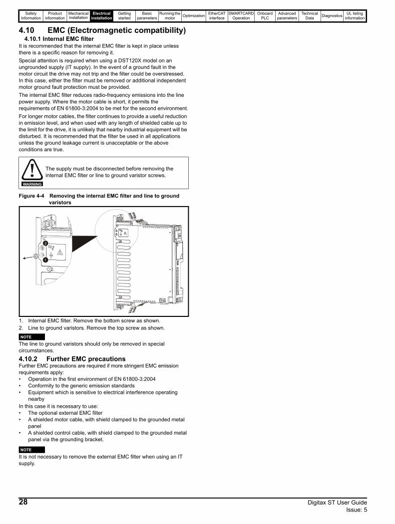
Safety Information
Product information
Mechanical installation
Electrical installation
Getting started
Basic parameters
Running the motor Optimization EtherCAT
interfaceSMARTCARD
OperationOnboard
PLCAdvanced
parametersTechnical
Data Diagnostics UL listing information
4.10 EMC (Electromagnetic compatibility)4.10.1 Internal EMC filter
It is recommended that the internal EMC filter is kept in place unless there is a specific reason for removing it.Special attention is required when using a DST120X model on an ungrounded supply (IT supply). In the event of a ground fault in the motor circuit the drive may not trip and the filter could be overstressed. In this case, either the filter must be removed or additional independent motor ground fault protection must be provided.The internal EMC filter reduces radio-frequency emissions into the line power supply. Where the motor cable is short, it permits the requirements of EN 61800-3:2004 to be met for the second environment.For longer motor cables, the filter continues to provide a useful reduction in emission level, and when used with any length of shielded cable up to the limit for the drive, it is unlikely that nearby industrial equipment will be disturbed. It is recommended that the filter be used in all applications unless the ground leakage current is unacceptable or the above conditions are true.
Figure 4-4 Removing the internal EMC filter and line to ground varistors
1. Internal EMC filter. Remove the bottom screw as shown.2. Line to ground varistors. Remove the top screw as shown.
The line to ground varistors should only be removed in special circumstances.
4.10.2 Further EMC precautionsFurther EMC precautions are required if more stringent EMC emission requirements apply:• Operation in the first environment of EN 61800-3:2004• Conformity to the generic emission standards• Equipment which is sensitive to electrical interference operating
nearbyIn this case it is necessary to use:• The optional external EMC filter• A shielded motor cable, with shield clamped to the grounded metal
panel• A shielded control cable, with shield clamped to the grounded metal
panel via the grounding bracket.
It is not necessary to remove the external EMC filter when using an IT supply.
The supply must be disconnected before removing the internal EMC filter or line to ground varistor screws.
WARNING
1
2
NOTE
NOTE
28 Digitax ST User Guide Issue: 5
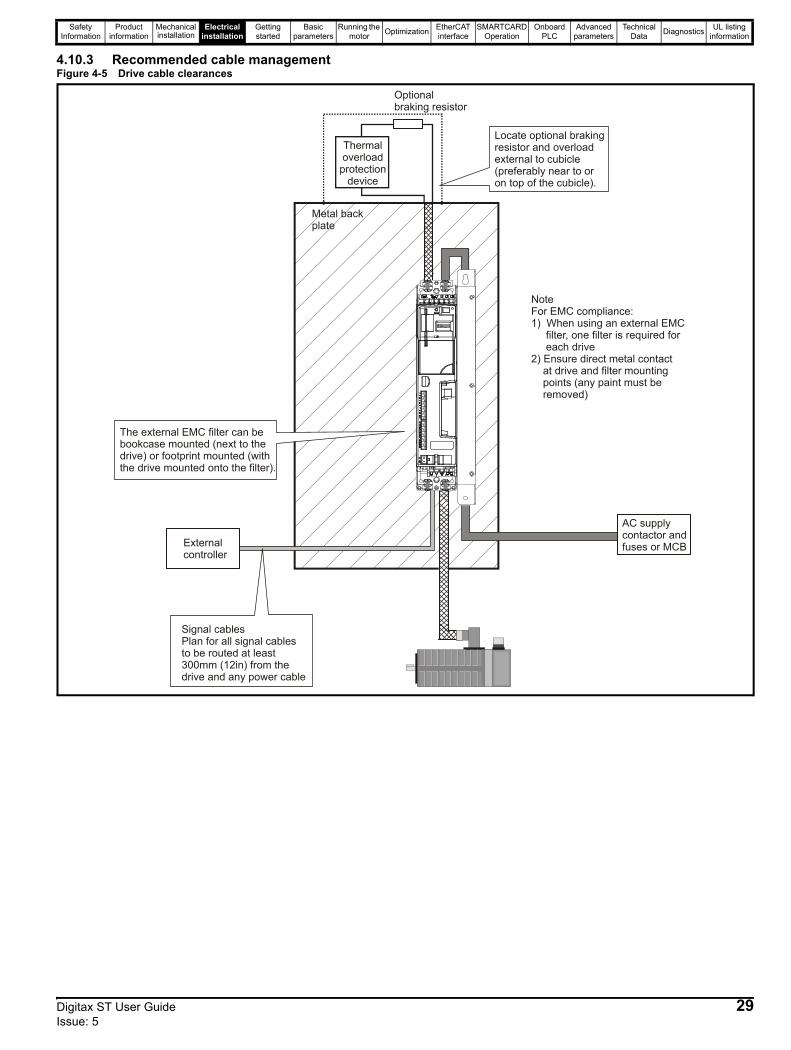
Safety Information
Product information
Mechanical installation
Electrical installation
Getting started
Basic parameters
Running the motor Optimization EtherCAT
interfaceSMARTCARD
OperationOnboard
PLCAdvanced
parametersTechnical
Data Diagnostics UL listing information
4.10.3 Recommended cable managementFigure 4-5 Drive cable clearances
Metal backplate
Externalcontroller
Signal cablesPlan for all signal cablesto be routed at least300mm (12in) from thedrive and any power cable
Optional braking resistor
Locate optional braking resistor and overload external to cubicle (preferably near to or on top of the cubicle).
NoteFor EMC compliance:1) When using an external EMC filter, one filter is required for each drive 2) Ensure direct metal contact at drive and filter mounting points (any paint must be removed)
The external EMC filter can be bookcase mounted (next to the drive) or footprint mounted (with the drive mounted onto the filter).
Thermaloverloadprotection
device
AC supply contactor and fuses or MCB
Digitax ST User Guide 29Issue: 5
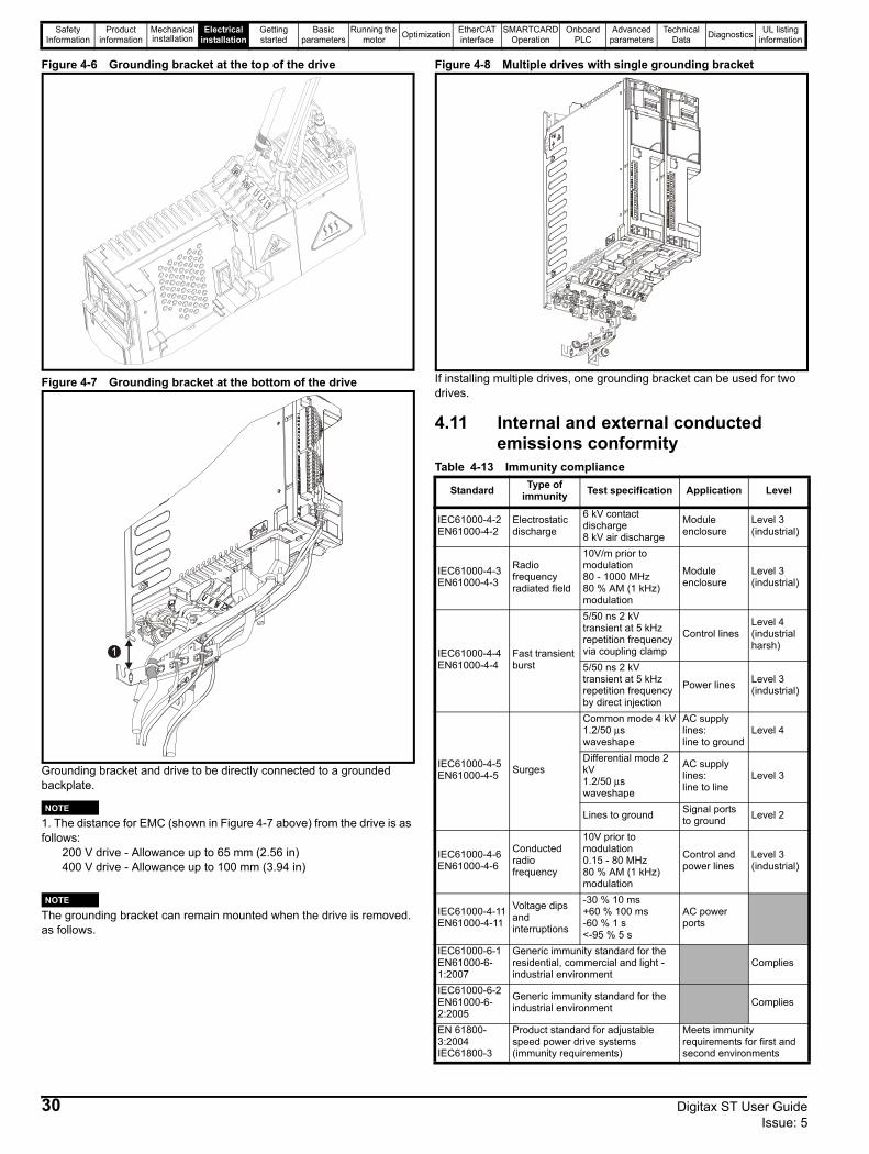
Safety Information
Product information
Mechanical installation
Electrical installation
Getting started
Basic parameters
Running the motor Optimization EtherCAT
interfaceSMARTCARD
OperationOnboard
PLCAdvanced
parametersTechnical
Data Diagnostics UL listing information
Figure 4-6 Grounding bracket at the top of the drive
Figure 4-7 Grounding bracket at the bottom of the drive
Grounding bracket and drive to be directly connected to a grounded backplate.
1. The distance for EMC (shown in Figure 4-7 above) from the drive is as follows:
200 V drive - Allowance up to 65 mm (2.56 in)400 V drive - Allowance up to 100 mm (3.94 in)
The grounding bracket can remain mounted when the drive is removed. as follows.
Figure 4-8 Multiple drives with single grounding bracket
If installing multiple drives, one grounding bracket can be used for two drives.
4.11 Internal and external conducted emissions conformity
Table 4-13 Immunity compliance
1
NOTE
NOTE
Standard Type of immunity Test specification Application Level
IEC61000-4-2 EN61000-4-2
Electrostatic discharge
6 kV contact discharge8 kV air discharge
Module enclosure
Level 3(industrial)
IEC61000-4-3EN61000-4-3
Radio frequency radiated field
10V/m prior to modulation80 - 1000 MHz80 % AM (1 kHz) modulation
Module enclosure
Level 3(industrial)
IEC61000-4-4EN61000-4-4
Fast transient burst
5/50 ns 2 kV transient at 5 kHz repetition frequency via coupling clamp
Control linesLevel 4(industrial harsh)
5/50 ns 2 kV transient at 5 kHz repetition frequency by direct injection
Power lines Level 3(industrial)
IEC61000-4-5EN61000-4-5 Surges
Common mode 4 kV1.2/50 μs waveshape
AC supply lines:line to ground
Level 4
Differential mode 2 kV1.2/50 μs waveshape
AC supply lines:line to line
Level 3
Lines to ground Signal ports to ground Level 2
IEC61000-4-6EN61000-4-6
Conducted radio frequency
10V prior to modulation0.15 - 80 MHz80 % AM (1 kHz) modulation
Control and power lines
Level 3(industrial)
IEC61000-4-11EN61000-4-11
Voltage dips and interruptions
-30 % 10 ms+60 % 100 ms-60 % 1 s<-95 % 5 s
AC power ports
IEC61000-6-1EN61000-6-1:2007
Generic immunity standard for the residential, commercial and light - industrial environment
Complies
IEC61000-6-2EN61000-6-2:2005
Generic immunity standard for the industrial environment Complies
EN 61800-3:2004IEC61800-3
Product standard for adjustable speed power drive systems (immunity requirements)
Meets immunity requirements for first and second environments
30 Digitax ST User Guide Issue: 5
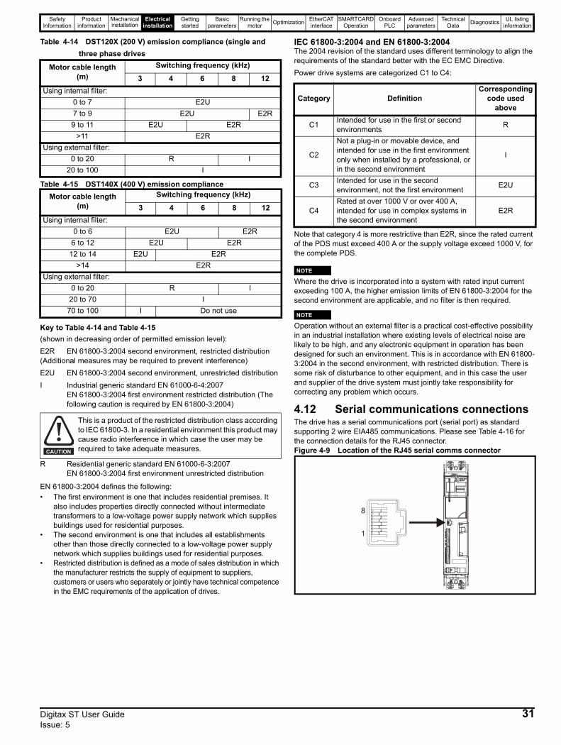
Safety Information
Product information
Mechanical installation
Electrical installation
Getting started
Basic parameters
Running the motor Optimization EtherCAT
interfaceSMARTCARD
OperationOnboard
PLCAdvanced
parametersTechnical
Data Diagnostics UL listing information
Table 4-14 DST120X (200 V) emission compliance (single and three phase drives
Table 4-15 DST140X (400 V) emission compliance
Key to Table 4-14 and Table 4-15(shown in decreasing order of permitted emission level):E2R EN 61800-3:2004 second environment, restricted distribution (Additional measures may be required to prevent interference)E2U EN 61800-3:2004 second environment, unrestricted distributionI Industrial generic standard EN 61000-6-4:2007
EN 61800-3:2004 first environment restricted distribution (The following caution is required by EN 61800-3:2004)
R Residential generic standard EN 61000-6-3:2007EN 61800-3:2004 first environment unrestricted distribution
EN 61800-3:2004 defines the following:• The first environment is one that includes residential premises. It
also includes properties directly connected without intermediate transformers to a low-voltage power supply network which supplies buildings used for residential purposes.
• The second environment is one that includes all establishments other than those directly connected to a low-voltage power supply network which supplies buildings used for residential purposes.
• Restricted distribution is defined as a mode of sales distribution in which the manufacturer restricts the supply of equipment to suppliers, customers or users who separately or jointly have technical competence in the EMC requirements of the application of drives.
IEC 61800-3:2004 and EN 61800-3:2004The 2004 revision of the standard uses different terminology to align the requirements of the standard better with the EC EMC Directive.Power drive systems are categorized C1 to C4:
Note that category 4 is more restrictive than E2R, since the rated current of the PDS must exceed 400 A or the supply voltage exceed 1000 V, for the complete PDS.
NWhere the drive is incorporated into a system with rated input current exceeding 100 A, the higher emission limits of EN 61800-3:2004 for the second environment are applicable, and no filter is then required.
NOperation without an external filter is a practical cost-effective possibility in an industrial installation where existing levels of electrical noise are likely to be high, and any electronic equipment in operation has been designed for such an environment. This is in accordance with EN 61800-3:2004 in the second environment, with restricted distribution. There is some risk of disturbance to other equipment, and in this case the user and supplier of the drive system must jointly take responsibility for correcting any problem which occurs.
4.12 Serial communications connectionsThe drive has a serial communications port (serial port) as standard supporting 2 wire EIA485 communications. Please see Table 4-16 for the connection details for the RJ45 connector.Figure 4-9 Location of the RJ45 serial comms connector
Motor cable length (m)
Switching frequency (kHz)
3 4 6 8 12Using internal filter:
0 to 7 E2U7 to 9 E2U E2R9 to 11 E2U E2R
>11 E2RUsing external filter:
0 to 20 R I20 to 100 I
Motor cable length (m)
Switching frequency (kHz)
3 4 6 8 12Using internal filter:
0 to 6 E2U E2R6 to 12 E2U E2R
12 to 14 E2U E2R>14 E2R
Using external filter:0 to 20 R I
20 to 70 I70 to 100 I Do not use
This is a product of the restricted distribution class according to IEC 61800-3. In a residential environment this product may cause radio interference in which case the user may be required to take adequate measures.CAUTION
Category DefinitionCorresponding
code used above
C1 Intended for use in the first or second environments R
C2
Not a plug-in or movable device, and intended for use in the first environment only when installed by a professional, or in the second environment
I
C3 Intended for use in the second environment, not the first environment E2U
C4Rated at over 1000 V or over 400 A, intended for use in complex systems in the second environment
E2R
NOTE
NOTE
8
1
Digitax ST User Guide 31Issue: 5
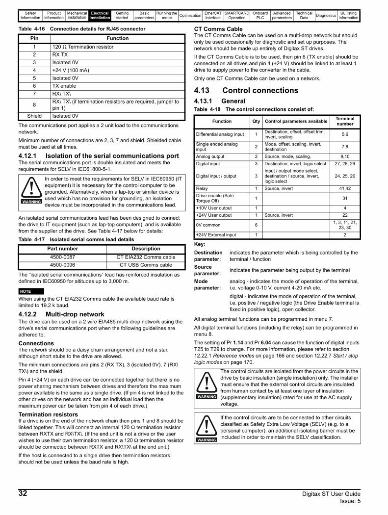
Safety Information
Product information
Mechanical installation
Electrical installation
Getting started
Basic parameters
Running the motor Optimization EtherCAT
interfaceSMARTCARD
OperationOnboard
PLCAdvanced
parametersTechnical
Data Diagnostics UL listing information
Table 4-16 Connection details for RJ45 connector
The communications port applies a 2 unit load to the communications network.Minimum number of connections are 2, 3, 7 and shield. Shielded cable must be used at all times.
4.12.1 Isolation of the serial communications portThe serial communications port is double insulated and meets the requirements for SELV in IEC61800-5-1.
An isolated serial communications lead has been designed to connect the drive to IT equipment (such as lap-top computers), and is available from the supplier of the drive. See Table 4-17 below for details:Table 4-17 Isolated serial comms lead details
The “isolated serial communications” lead has reinforced insulation as defined in IEC60950 for altitudes up to 3,000 m.
NWhen using the CT EIA232 Comms cable the available baud rate is limited to 19.2 k baud.
4.12.2 Multi-drop networkThe drive can be used on a 2 wire EIA485 multi-drop network using the drive's serial communications port when the following guidelines are adhered to.
ConnectionsThe network should be a daisy chain arrangement and not a star, although short stubs to the drive are allowed.The minimum connections are pins 2 (RX TX), 3 (isolated 0V), 7 (RX\ TX\) and the shield.Pin 4 (+24 V) on each drive can be connected together but there is no power sharing mechanism between drives and therefore the maximum power available is the same as a single drive. (If pin 4 is not linked to the other drives on the network and has an individual load then the maximum power can be taken from pin 4 of each drive.)
Termination resistorsIf a drive is on the end of the network chain then pins 1 and 8 should be linked together. This will connect an internal 120 Ω termination resistor between RXTX and RX\TX\. (If the end unit is not a drive or the user wishes to use their own termination resistor, a 120 Ω termination resistor should be connected between RXTX and RX\TX\ at the end unit.) If the host is connected to a single drive then termination resistors should not be used unless the baud rate is high.
CT Comms CableThe CT Comms Cable can be used on a multi-drop network but should only be used occasionally for diagnostic and set up purposes. The network should be made up entirely of Digitax ST drives.If the CT Comms Cable is to be used, then pin 6 (TX enable) should be connected on all drives and pin 4 (+24 V) should be linked to at least 1 drive to supply power to the converter in the cable.Only one CT Comms Cable can be used on a network.
4.13 Control connections4.13.1 GeneralTable 4-18 The control connections consist of:
Key:
All analog terminal functions can be programmed in menu 7.All digital terminal functions (including the relay) can be programmed in menu 8.The setting of Pr 1.14 and Pr 6.04 can cause the function of digital inputs T25 to T29 to change. For more information, please refer to section 12.22.1 Reference modes on page 166 and section 12.22.7 Start / stop logic modes on page 170.
Pin Function1 120 Ω Termination resistor2 RX TX3 Isolated 0V4 +24 V (100 mA)5 Isolated 0V6 TX enable7 RX\ TX\
8 RX\ TX\ (if termination resistors are required, jumper to pin 1)
Shield Isolated 0V
In order to meet the requirements for SELV in IEC60950 (IT equipment) it is necessary for the control computer to be grounded. Alternatively, when a lap-top or similar device is used which has no provision for grounding, an isolation device must be incorporated in the communications lead.
Part number Description4500-0087 CT EIA232 Comms cable4500-0096 CT USB Comms cable
WARNING
NOTE
Function Qty Control parameters available Terminal number
Differential analog input 1 Destination, offset, offset trim, invert, scaling 5,6
Single ended analog input 2 Mode, offset, scaling, invert,
destination 7,8
Analog output 2 Source, mode, scaling, 9,10Digital input 3 Destination, invert, logic select 27, 28, 29
Digital input / output 3Input / output mode select, destination / source, invert, logic select
24, 25, 26
Relay 1 Source, invert 41,42Drive enable (Safe Torque Off) 1 31
+10V User output 1 4+24V User output 1 Source, invert 22
0V common 6 1, 3, 11, 21, 23, 30
+24V External input 1 2
Destination parameter:
indicates the parameter which is being controlled by the terminal / function
Source parameter: indicates the parameter being output by the terminal
Mode parameter:
analog - indicates the mode of operation of the terminal, i.e. voltage 0-10 V, current 4-20 mA etc. digital - indicates the mode of operation of the terminal, i.e. positive / negative logic (the Drive Enable terminal is fixed in positive logic), open collector.
The control circuits are isolated from the power circuits in the drive by basic insulation (single insulation) only. The installer must ensure that the external control circuits are insulated from human contact by at least one layer of insulation (supplementary insulation) rated for use at the AC supply voltage.
If the control circuits are to be connected to other circuits classified as Safety Extra Low Voltage (SELV) (e.g. to a personal computer), an additional isolating barrier must be included in order to maintain the SELV classification.
WARNING
WARNING
32 Digitax ST User Guide Issue: 5
Safety Information
Product information
Mechanical installation
Electrical installation
Getting started
Basic parameters
Running the motor Optimization EtherCAT
interfaceSMARTCARD
OperationOnboard
PLCAdvanced
parametersTechnical
Data Diagnostics UL listing information
NAny signal cables which are carried inside the motor cable (i.e. motor thermistor, motor brake) will pick up large pulse currents via the cable capacitance. The shield of these signal cables must be connected to ground close to the point of exit of the motor cable, to avoid this noise current spreading through the control system.
NThe Safe Torque Off drive enable terminal is a positive logic input only. It is not affected by the setting of Pr 8.29 Positive logic select.
NThe common 0V from analog signals should, wherever possible, not be connected to the same 0V terminal as the common 0V from digital signals. Terminals 3 and 11 should be used for connecting the 0V common of analog signals and terminals 21, 23 and 30 for digital signals. This is to prevent small voltage drops in the terminal connections causing inaccuracies in the analog signals.
If any of the digital inputs or outputs (including the drive enable input) are connected in parallel with an inductive load (i.e. contactor or motor brake) then suitable suppression (i.e. diode or varistor) should be used on the coil of the load. If no suppression is used then over voltage spikes can cause damage to the digital inputs and outputs on the drive.
Ensure the logic sense is correct for the control circuit to be used. Incorrect logic sense could cause the motor to be started unexpectedly.Positive logic is the default state for the drive.
CAUTION
CAUTION
NOTE
NOTE
NOTE
Digitax ST User Guide 33Issue: 5

Safety Information
Product information
Mechanical installation
Electrical installation
Getting started
Basic parameters
Running the motor Optimization EtherCAT
interfaceSMARTCARD
OperationOnboard
PLCAdvanced
parametersTechnical
Data Diagnostics UL listing information
4.14 Control terminals
Figure 4-10 Default terminal functions
For control terminal specification, refer to Chapter 4.14.1 Control terminal specification on page 35.
If Terminal 31 is used as a Safe Torque Off function, the cable must be shielded or segregated.
The control circuits are isolated from the power circuits in the drive by basic insulation (single insulation) only. The installer must ensure that the external control circuits are insulated from human contact by at least one layer of insulation (supplementary insulation) rated for use at the AC supply voltage.WARNING
0V commonExternal 24V supply
0V common
Analog speed reference 1
Connections for single-ended input
signal
Connections for differential input signal
0V common
0V common
0V common
Analog input 2
Analog input 1
0V common
1
2
5
6
3
21
22
23
24
25
26
27
28
29
30
31
41
42
At zero speed
Reset
Run forward
Run reverseAnalog input 1/
input 2 select
Jog forward select
SAFE TORQUE OFF (drive enable)
Status relay(Overvoltage
category II)
Drive OK
Speed
0V common
Analog speed
reference 2
4
7
11
9
10
8
Torque (active current)
Analog input 3Motor thermistor
Connectors specification:Maximum size of controlconnections cable = 1.5mm (16AWG)2
Torque setting = 0.2 N m (1.8 lb in)
Status relay cable = 2.5mm (12AWG)2
Torque setting = 0.5 N m (4.4 lb in)
Polarizedsignalconnections
NOTE
34 Digitax ST User Guide Issue: 5
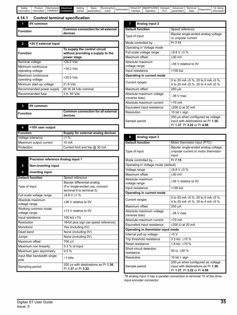
Safety Information
Product information
Mechanical installation
Electrical installation
Getting started
Basic parameters
Running the motor Optimization EtherCAT
interfaceSMARTCARD
OperationOnboard
PLCAdvanced
parametersTechnical
Data Diagnostics UL listing information
4.14.1 Control terminal specification
T8 analog input 3 has a parallel connection to terminal 15 of the drive input encoder connector.
1 0V common
Function Common connection for all external devices
2 +24 V external input
FunctionTo supply the control circuit without providing a supply to the power stage
Nominal voltage +24.0 VdcMinimum continuous operating voltage +19.2 Vdc
Maximum continuous operating voltage +30.0 Vdc
Minimum start-up voltage 21.6 VdcRecommended power supply 60 W 24 Vdc nominalRecommended fuse 3 A, 50 Vdc
3 0V common
Function Common connection for all external devices
4 +10V user output
Function Supply for external analog devicesVoltage tolerance ±1 %Maximum output current 10 mAProtection Current limit and trip @ 30 mA
Precision reference Analog input 1
5 Non-inverting input
6 Inverting input
Default function Speed reference
Type of inputBipolar differential analog(For single-ended use, connect terminal 6 to terminal 3)
Full scale voltage range ±9.8 V ±1 %Absolute maximum voltage range ±36 V relative to 0V
Working common mode voltage range ±13 V relative to 0V
Input resistance 100 kΩ ±1%Resolution 16-bit plus sign (as speed reference)Monotonic Yes (including 0V)Dead band None (including 0V)Jumps None (including 0V)Maximum offset 700 μVMaximum non linearity 0.3 % of inputMaximum gain asymmetry 0.5 %Input filter bandwidth single pole ~1 kHz
Sampling period 250 μs with destinations as Pr 1.36, Pr 1.37 or Pr 3.22.
7 Analog input 2
Default function Speed reference
Type of input Bipolar single-ended analog voltage or unipolar current
Mode controlled by... Pr 7.11Operating in Voltage modeFull scale voltage range ±9.8 V ±3 %Maximum offset ±30 mVAbsolute maximum voltage range ±36 V relative to 0V
Input resistance >100 kΩOperating in current mode
Current ranges 0 to 20 mA ±5 %, 20 to 0 mA ±5 %,4 to 20 mA ±5 %, 20 to 4 mA ±5 %
Maximum offset 250 μAAbsolute maximum voltage (reverse bias) −36 V max
Absolute maximum current +70 mAEquivalent input resistance ≤200 Ω at 20 mAResolution 10 bit + sign
Sample period250 μs when configured as voltage input with destinations as Pr 1.36, Pr 1.37, Pr 3.22 or Pr 4.08.
8 Analog input 3
Default function Motor thermistor input (PTC)
Type of inputBipolar single-ended analog voltage, unipolar current or motor thermistor input
Mode controlled by... Pr 7.15Operating in Voltage mode (default)Voltage range ±9.8 V ±3 %Maximum offset ±30 mVAbsolute maximum voltage range ±36 V relative to 0V
Input resistance >100 kΩOperating in current mode
Current ranges 0 to 20 mA ±5 %, 20 to 0 mA ±5 %,4 to 20 mA ±5 %, 20 to 4 mA ±5 %
Maximum offset 250 μAAbsolute maximum voltage (reverse bias) −36 V max
Absolute maximum current +70 mAEquivalent input resistance ≤200 Ω at 20 mAOperating in thermistor input modeInternal pull-up voltage <5 VTrip threshold resistance 3.3 kΩ ±10 %Reset resistance 1.8 kΩ ±10 %Short-circuit detection resistance 50 Ω ±30 %
Resolution 10 bit + sign
Sample period250 μs when configured as voltage input with destinations as Pr 1.36, Pr 1.37, Pr 3.22 or Pr 4.08.
Digitax ST User Guide 35Issue: 5
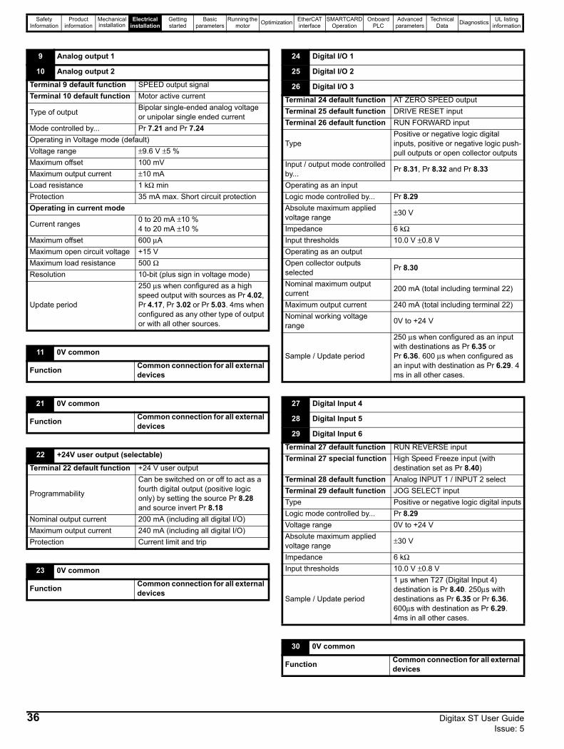
Safety Information
Product information
Mechanical installation
Electrical installation
Getting started
Basic parameters
Running the motor Optimization EtherCAT
interfaceSMARTCARD
OperationOnboard
PLCAdvanced
parametersTechnical
Data Diagnostics UL listing information
9 Analog output 1
10 Analog output 2
Terminal 9 default function SPEED output signalTerminal 10 default function Motor active current
Type of output Bipolar single-ended analog voltage or unipolar single ended current
Mode controlled by... Pr 7.21 and Pr 7.24 Operating in Voltage mode (default)Voltage range ±9.6 V ±5 %Maximum offset 100 mVMaximum output current ±10 mALoad resistance 1 kΩ minProtection 35 mA max. Short circuit protectionOperating in current mode
Current ranges 0 to 20 mA ±10 %4 to 20 mA ±10 %
Maximum offset 600 μAMaximum open circuit voltage +15 VMaximum load resistance 500 ΩResolution 10-bit (plus sign in voltage mode)
Update period
250 μs when configured as a high speed output with sources as Pr 4.02, Pr 4.17, Pr 3.02 or Pr 5.03. 4ms when configured as any other type of output or with all other sources.
11 0V common
Function Common connection for all external devices
21 0V common
Function Common connection for all external devices
22 +24V user output (selectable)
Terminal 22 default function +24 V user output
Programmability
Can be switched on or off to act as a fourth digital output (positive logic only) by setting the source Pr 8.28 and source invert Pr 8.18
Nominal output current 200 mA (including all digital I/O)Maximum output current 240 mA (including all digital I/O)Protection Current limit and trip
23 0V common
Function Common connection for all external devices
24 Digital I/O 1
25 Digital I/O 2
26 Digital I/O 3
Terminal 24 default function AT ZERO SPEED outputTerminal 25 default function DRIVE RESET inputTerminal 26 default function RUN FORWARD input
TypePositive or negative logic digital inputs, positive or negative logic push-pull outputs or open collector outputs
Input / output mode controlled by... Pr 8.31, Pr 8.32 and Pr 8.33
Operating as an inputLogic mode controlled by... Pr 8.29Absolute maximum applied voltage range ±30 V
Impedance 6 kΩInput thresholds 10.0 V ±0.8 VOperating as an outputOpen collector outputs selected Pr 8.30
Nominal maximum output current 200 mA (total including terminal 22)
Maximum output current 240 mA (total including terminal 22)Nominal working voltage range 0V to +24 V
Sample / Update period
250 μs when configured as an input with destinations as Pr 6.35 or Pr 6.36. 600 μs when configured as an input with destination as Pr 6.29. 4 ms in all other cases.
27 Digital Input 4
28 Digital Input 5
29 Digital Input 6
Terminal 27 default function RUN REVERSE inputTerminal 27 special function High Speed Freeze input (with
destination set as Pr 8.40)Terminal 28 default function Analog INPUT 1 / INPUT 2 selectTerminal 29 default function JOG SELECT inputType Positive or negative logic digital inputsLogic mode controlled by... Pr 8.29Voltage range 0V to +24 VAbsolute maximum applied voltage range ±30 V
Impedance 6 kΩInput thresholds 10.0 V ±0.8 V
Sample / Update period
1 µs when T27 (Digital Input 4) destination is Pr 8.40. 250μs with destinations as Pr 6.35 or Pr 6.36. 600μs with destination as Pr 6.29. 4ms in all other cases.
30 0V common
Function Common connection for all external devices
36 Digitax ST User Guide Issue: 5
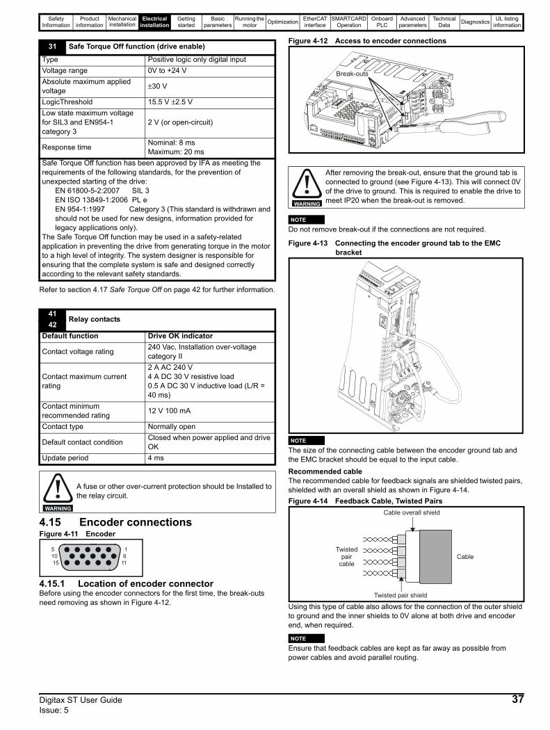
Safety Information
Product information
Mechanical installation
Electrical installation
Getting started
Basic parameters
Running the motor Optimization EtherCAT
interfaceSMARTCARD
OperationOnboard
PLCAdvanced
parametersTechnical
Data Diagnostics UL listing information
Refer to section 4.17 Safe Torque Off on page 42 for further information.
4.15 Encoder connectionsFigure 4-11 Encoder
4.15.1 Location of encoder connectorBefore using the encoder connectors for the first time, the break-outs need removing as shown in Figure 4-12.
Figure 4-12 Access to encoder connections
Do not remove break-out if the connections are not required.
Figure 4-13 Connecting the encoder ground tab to the EMC bracket
The size of the connecting cable between the encoder ground tab and the EMC bracket should be equal to the input cable.Recommended cable The recommended cable for feedback signals are shielded twisted pairs, shielded with an overall shield as shown in Figure 4-14.Figure 4-14 Feedback Cable, Twisted Pairs
Using this type of cable also allows for the connection of the outer shield to ground and the inner shields to 0V alone at both drive and encoder end, when required.
Ensure that feedback cables are kept as far away as possible from power cables and avoid parallel routing.
31 Safe Torque Off function (drive enable)
Type Positive logic only digital inputVoltage range 0V to +24 VAbsolute maximum applied voltage ±30 V
LogicThreshold 15.5 V ±2.5 VLow state maximum voltage for SIL3 and EN954-1 category 3
2 V (or open-circuit)
Response time Nominal: 8 msMaximum: 20 ms
Safe Torque Off function has been approved by IFA as meeting the requirements of the following standards, for the prevention of unexpected starting of the drive:
EN 61800-5-2:2007 SIL 3EN ISO 13849-1:2006 PL eEN 954-1:1997 Category 3 (This standard is withdrawn and should not be used for new designs, information provided for legacy applications only).
The Safe Torque Off function may be used in a safety-related application in preventing the drive from generating torque in the motor to a high level of integrity. The system designer is responsible for ensuring that the complete system is safe and designed correctly according to the relevant safety standards.
41Relay contacts
42Default function Drive OK indicator
Contact voltage rating 240 Vac, Installation over-voltage category II
Contact maximum current rating
2 A AC 240 V4 A DC 30 V resistive load0.5 A DC 30 V inductive load (L/R = 40 ms)
Contact minimum recommended rating 12 V 100 mA
Contact type Normally open
Default contact condition Closed when power applied and drive OK
Update period 4 ms
A fuse or other over-current protection should be Installed to the relay circuit.
WARNING
51015
16
11
After removing the break-out, ensure that the ground tab is connected to ground (see Figure 4-13). This will connect 0V of the drive to ground. This is required to enable the drive to meet IP20 when the break-out is removed.
Break-outs
WARNING
NOTE
NOTE
Twistedpair
cable
Twisted pair shield
Cable
Cable overall shield
NOTE
Digitax ST User Guide 37Issue: 5

Safety Information
Product information
Mechanical installation
Electrical installation
Getting started
Basic parameters
Running the motor Optimization EtherCAT
interfaceSMARTCARD
OperationOnboard
PLCAdvanced
parametersTechnical
Data Diagnostics UL listing information
Figure 4-15 Feedback cable connections
4.16 Encoder terminalsFigure 4-16 Location of encoder connectors on underside of drive
4.16.1 Encoder In connectionsTable 4-19 Encoder types
* This feedback device provides very low resolution feedback and should not be used for applications requiring a high level of performance** The U, V & W commutation signals are required with an incremental type encoder when used with a servo motor. The UVW commutation
signals are used to define the motor position during the first 120° electrical rotation after the drive is powered-up or the encoder is initialized.
Drive encoder input converter connectorA 15-way D-type converter is available to provide a screw terminal interface for encoder wiring, and a spade terminal for the shield.Figure 4-17 Drive encoder input converter connector
Cable
Cable shield
Twisted pair
shield
Cable shield
Twisted pair
shield
Connectionat motor
Connectionat drive
Ground clamp or grounding bracket on shield
Shield connection
to 0V
Shield connection
to 0V
Setting of Pr 3.38 Description
Ab(0)
Quadrature incremental encoder with or without marker pulse
Fd(1)
Incremental encoder with frequency pulses and direction, with or without marker pulse
Fr(2)
Incremental encoder with forward pulses and reverse pulses, with or without marker pulse
Ab.SErVO(3)
Quadrature incremental encoder with UVW commutation signals, with or without marker pulseEncoder with UVW commutation signals only (Pr 3.34 set to zero)*
Fd.SErVO(4)
Incremental encoder with frequency pulses and directionwith commutation signals**, with or without marker pulse
Fr.SErVO(5)
Incremental encoder with forward pulses and reverse pulses with commutation signals**, with or without marker pulse
SC(6) SinCos encoder without serial communications
SC.HiPEr(7)
Absolute SinCos encoder with HiperFace serial communications protocol (Stegmann)
EndAt(8)
Absolute EndAt serial communications encoder (Heidenhain)
SC.EndAt(9)
Absolute SinCos encoder with EnDat serial communications protocol (Heidenhain)
SSI(10) Absolute SSI only encoder
SC.SSI(11) Absolute SinCos encoder with SSI
51015
16
11
Drive encoder connectorFemale 15-way D-type
Encoderinput
Bufferedencoder
output
If using the Drive Encoder Input Converter connector, the Single Ended Encoder Interface or the ERN1387 Encoder Interface protection to at least IP2X must be provided for the connector.WARNING
38 Digitax ST User Guide Issue: 5

Safety Information
Product information
Mechanical installation
Electrical installation
Getting started
Basic parameters
Running the motor Optimization EtherCAT
interfaceSMARTCARD
OperationOnboard
PLCAdvanced
parametersTechnical
Data Diagnostics UL listing information
Table 4-20 Encoder In connector details
* Marker pulse is optional** The encoder supply is selectable through parameter configuration to 5 Vdc, 8 Vdc and 15 Vdc*** Terminal 15 is a parallel connection to T8 analog input 3. If this is to be used as a thermistor input, ensure that Pr 7.15 is set to ‘th.sc’ (7), ‘th’ (8)
or ‘th.diSP’ (9)
Table 4-21 Simulated encoder output connector details
SSI encoders typically have maximum baud rate of 500 kBaud. When a SSI only encoder is used for speed feedback with a servo motor, a large speed feedback filter (Pr 3.42) is required due to the time taken for the position information to be transferred from the encoder into the drive. The addition of this filter means that SSI only encoders are not suitable for speed feedback in dynamic or high-speed applications.
SpecificationsFeedback device connectionsAb, Fd, Fr, Ab.SErVO, Fd.SErVO and Fr.SErVO encoders
Term.Setting of Pr 3.38
Ab (0)
Fd (1)
Fr (2)
Ab.SErVO(3)
Fd.SErVO(4)
Fr.SErVO(5)
SC(6)
SC.HiPEr(7)
EndAt(8)
SC.EndAt(9)
SSI(10)
SC.SSI(11)
1 A F F A F F Cos Cos Cos2 A\ F\ F\ A\ F\ F\ Cosref Cosref Cosref3 B D R B D R Sin Sin Sin4 B\ D\ R\ B\ D\ R\ Sinref Sinref Sinref5 Z* Encoder input - Data (input/output)6 Z\* Encoder input - Data\ (input/output)7 U8 U\9 V
10 V\11 W Encoder input - Clock (output)12 W\ Encoder input - Clock\ (output) 13 +V**14 0V common15 th***
Shell 0V common
Term.Setting of Pr 3.54
Ab (0)
Fd (1)
Fr (2)
Ab.L(3)
Fd.L(4)
1 A F F A F2 A\ F\ F\ A\ F\3 B D R B D4 B\ D\ R\ B\ D\5 Z*6 Z\*
14 0VShell 0V common
1 Channel A, Frequency or Forward inputs
2 Channel A\, Frequency\ or Forward\ inputs
3 Channel B, Direction or Reverse inputs
4 Channel B\, Direction\ or Reverse\ inputs
Type EIA 485 differential receiversMaximum input frequency 500 kHzLine loading <2 unit loadsLine termination components 120 Ω (switchable)Working common mode range +12 V to –7 VAbsolute maximum applied voltage relative to 0V ±25 V
Absolute maximum applied differential voltage ±25 V
NOTE
5 Marker pulse channel Z
6 Marker pulse channel Z\
7 Phase channel U
8 Phase channel U\
9 Phase channel V
10 Phase channel V\
11 Phase channel W
12 Phase channel W\
Type EIA 485 differential receivers
Maximum input frequency 512 kHz
Line loading 32 unit loads (for terminals 5 and 6)1 unit load (for terminals 7 to 12)
Line termination components120 Ω (switchable for terminals 5 and 6, always in circuit for terminals 7 to 12)
Working common mode range +12 V to –7 V
Absolute maximum applied voltage relative to 0V +14 V to -9 V
Absolute maximum applied differential voltage +14 V to -9 V
Digitax ST User Guide 39Issue: 5
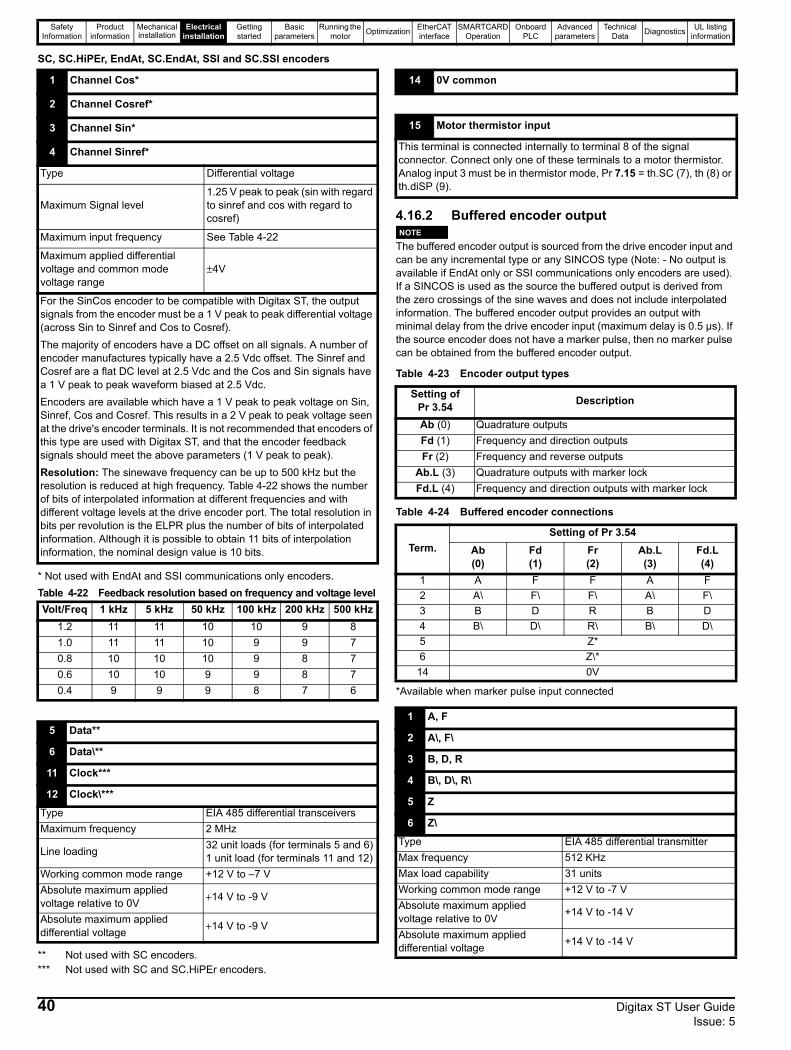
Safety Information
Product information
Mechanical installation
Electrical installation
Getting started
Basic parameters
Running the motor Optimization EtherCAT
interfaceSMARTCARD
OperationOnboard
PLCAdvanced
parametersTechnical
Data Diagnostics UL listing information
SC, SC.HiPEr, EndAt, SC.EndAt, SSI and SC.SSI encoders
* Not used with EndAt and SSI communications only encoders.Table 4-22 Feedback resolution based on frequency and voltage level
** Not used with SC encoders.*** Not used with SC and SC.HiPEr encoders.
4.16.2 Buffered encoder output
The buffered encoder output is sourced from the drive encoder input and can be any incremental type or any SINCOS type (Note: - No output is available if EndAt only or SSI communications only encoders are used). If a SINCOS is used as the source the buffered output is derived from the zero crossings of the sine waves and does not include interpolated information. The buffered encoder output provides an output with minimal delay from the drive encoder input (maximum delay is 0.5 µs). If the source encoder does not have a marker pulse, then no marker pulse can be obtained from the buffered encoder output.
Table 4-23 Encoder output types
Table 4-24 Buffered encoder connections
*Available when marker pulse input connected
1 Channel Cos*
2 Channel Cosref*
3 Channel Sin*
4 Channel Sinref*
Type Differential voltage
Maximum Signal level1.25 V peak to peak (sin with regard to sinref and cos with regard to cosref)
Maximum input frequency See Table 4-22
Maximum applied differential voltage and common mode voltage range
±4V
For the SinCos encoder to be compatible with Digitax ST, the output signals from the encoder must be a 1 V peak to peak differential voltage (across Sin to Sinref and Cos to Cosref).The majority of encoders have a DC offset on all signals. A number of encoder manufactures typically have a 2.5 Vdc offset. The Sinref and Cosref are a flat DC level at 2.5 Vdc and the Cos and Sin signals have a 1 V peak to peak waveform biased at 2.5 Vdc.Encoders are available which have a 1 V peak to peak voltage on Sin, Sinref, Cos and Cosref. This results in a 2 V peak to peak voltage seen at the drive's encoder terminals. It is not recommended that encoders of this type are used with Digitax ST, and that the encoder feedback signals should meet the above parameters (1 V peak to peak).Resolution: The sinewave frequency can be up to 500 kHz but the resolution is reduced at high frequency. Table 4-22 shows the number of bits of interpolated information at different frequencies and with different voltage levels at the drive encoder port. The total resolution in bits per revolution is the ELPR plus the number of bits of interpolated information. Although it is possible to obtain 11 bits of interpolation information, the nominal design value is 10 bits.
Volt/Freq 1 kHz 5 kHz 50 kHz 100 kHz 200 kHz 500 kHz1.2 11 11 10 10 9 81.0 11 11 10 9 9 70.8 10 10 10 9 8 70.6 10 10 9 9 8 70.4 9 9 9 8 7 6
5 Data**
6 Data\**
11 Clock***
12 Clock\***
Type EIA 485 differential transceiversMaximum frequency 2 MHz
Line loading 32 unit loads (for terminals 5 and 6)1 unit load (for terminals 11 and 12)
Working common mode range +12 V to –7 VAbsolute maximum applied voltage relative to 0V +14 V to -9 V
Absolute maximum applied differential voltage +14 V to -9 V
14 0V common
15 Motor thermistor input
This terminal is connected internally to terminal 8 of the signal connector. Connect only one of these terminals to a motor thermistor. Analog input 3 must be in thermistor mode, Pr 7.15 = th.SC (7), th (8) or th.diSP (9).
Setting of Pr 3.54 Description
Ab (0) Quadrature outputsFd (1) Frequency and direction outputsFr (2) Frequency and reverse outputs
Ab.L (3) Quadrature outputs with marker lockFd.L (4) Frequency and direction outputs with marker lock
Term.Setting of Pr 3.54
Ab (0)
Fd (1)
Fr (2)
Ab.L(3)
Fd.L(4)
1 A F F A F2 A\ F\ F\ A\ F\3 B D R B D4 B\ D\ R\ B\ D\5 Z*6 Z\*
14 0V
1 A, F
2 A\, F\
3 B, D, R
4 B\, D\, R\
5 Z
6 Z\
Type EIA 485 differential transmitterMax frequency 512 KHzMax load capability 31 unitsWorking common mode range +12 V to -7 VAbsolute maximum applied voltage relative to 0V +14 V to -14 V
Absolute maximum applied differential voltage +14 V to -14 V
NOTE
40 Digitax ST User Guide Issue: 5

Safety Information
Product information
Mechanical installation
Electrical installation
Getting started
Basic parameters
Running the motor Optimization EtherCAT
interfaceSMARTCARD
OperationOnboard
PLCAdvanced
parametersTechnical
Data Diagnostics UL listing information
4.16.3 Digitax ST Plus additional connectionsFigure 4-18 Digitax ST Plus terminals view
The terminals are numbered from terminal 1 at the top, to terminal 13 at the bottom as per the orientation shown in Figure 4-18. The terminal functions are given in Table 4-25:Table 4-25 Digitax ST Plus connector details
4.16.4 Digitax ST EZMotion additional connectionsFigure 4-19 Digitax ST EZMotion terminals view
Table 4-26 Digitax EZMotion connector details
4.16.5 Digitax ST EtherCAT additional connectionsFigure 4-27 Digitax ST EtherCAT terminals view
Table 4-20 Digitax EtherCAT connector details
14 0V common
Terminal Function Description1 0V SC 0V connection for EIA-RS485 port
2 /RX EIA-RS485 Receive line (negative). Incoming.
3 RX EIA-RS485 Receive line (positive). Incoming.
4 /TX EIA-RS485 Transmit line (negative). Outgoing.
5 TX EIA-RS485 Transmit line (positive). Outgoing.
6 Fieldbus Type A Fieldbus Type data line
7 Fieldbus Type Shield Shield connection for Fieldbus Type
8 Fieldbus Type B Fieldbus Type data line9 0V 0V connection for digital I/O
10 DI0 Digital input 011 DI1 Digital input 112 DO0 Digital output 013 DO1 Digital output 1
1
13
Connector specification:
Maximum size cable = 1.5 mm2
Torque = 0.2 N m (1.8 lb in)
1
7
Connector specification:
Maximum size cable = 1.5 mm2
Torque = 0.2 N m (1.8 lb in)
Terminal Function Description1 0V common 0V common connection for digital I/O2 Input 1 Digital input 13 Input 2 Digital input 24 Input 3 Digital input 35 Input 4 Digital input 46 Output 1 Digital output 17 Output 2 Digital output 2
Terminal Function (A - IN) Terminal Function
(B - OUT)Digital Inputs Function
1 Transmit + 1 Transmit + 1 0V Common
2 Transmit - 2 Transmit - 2 Digital input 0
3 Receive + 3 Receive + 3 Digital input 1
4 Not used 4 Not used5 Not used 5 Not used6 Receive - 6 Receive -7 Not used 7 Not used8 Not used 8 Not used
1 0V common
Function Common connection for Digital I/O
2 Input 1
3 Input 2
4 Input 3
5 Input 4
Input turn on voltage 15 Vdc ± 0.5 VdcInput voltage range 0 Vdc to +24 VdcMaximum input voltage + 30 Vdc
6 Output 1
7 Output 2
Output voltage Depends on 24 Vdc supplyMaximum output current 20mA total for both outputs
1
7
12
3
AB
AB
Connector specification:
Maximum size cable = 1.5mm2
Torque = 0.2 N m (1.8 lb in)
Digitax ST User Guide 41Issue: 5
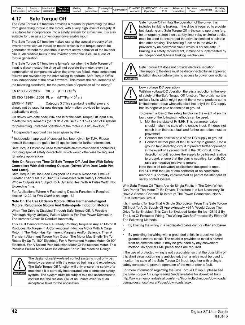
Safety Information
Product information
Mechanical installation
Electrical installation
Getting started
Basic parameters
Running the motor Optimization EtherCAT
interfaceSMARTCARD
OperationOnboard
PLCAdvanced
parametersTechnical
Data Diagnostics UL listing information
4.17 Safe Torque OffThe Safe Torque Off function provides a means for preventing the drive from generating torque in the motor, with a very high level of integrity. It is suitable for incorporation into a safety system for a machine. It is also suitable for use as a conventional drive enable input.The Safe Torque Off function makes use of the special property of an inverter drive with an induction motor, which is that torque cannot be generated without the continuous correct active behavior of the inverter circuit. All credible faults in the inverter power circuit cause a loss of torque generation.The Safe Torque Off function is fail-safe, so when the Safe Torque off input is disconnected the drive will not operate the motor, even if a combination of components within the drive has failed. Most component failures are revealed by the drive failing to operate. Safe Torque Off is also independent of the drive firmware. This meets the requirements of the following standards, for the prevention of operation of the motor.1
EN 61800-5-2:2007 SIL 3 (PFH ≤10-8)
EN ISO 13849-1:2006 PL e (MTTFD >105 yr)
EN954-1:1997 Category 3 (This standard is withdrawn and should not be used for new designs, information provided for legacy applications only).On drives with date code P04 and later the Safe Torque Off input also meets the requirements (of EN 81-1 clause 12.7.3 b) as part of a system for preventing unwanted operation of the motor in a lift (elevator).2
1 Independent approval has been given by IFA.2 Independent approval of concept has been given by TÜV. Please consult the separate guide for lift applications for further information.Safe Torque Off can be used to eliminate electro-mechanical contactors, including special safety contactors, which would otherwise be required for safety applications.Note On Response Time Of Safe Torque Off, And Use With Safety Controllers With Self-testing Outputs (Drives With Date Code P04 And Later).Safe Torque Off Has Been Designed To Have A Response Time Of Greater Than 1 Ms, So That It Is Compatible With Safety Controllers Whose Outputs Are Subject To A Dynamic Test With A Pulse Width Not Exceeding 1ms.For Applications Where A Fast-acting Disable Function Is Required, section 12.22.10 Fast Disable on page 172Note On The Use Of Servo Motors, Other Permanent-magnet Motors, Reluctance Motors And Salient-pole Induction MotorsWhen The Drive Is Disabled Through Safe Torque Off, A Possible (Although Highly Unlikely) Failure Mode Is For Two Power Devices In The Inverter Circuit To Conduct Incorrectly.This Fault Cannot Produce A Steady Rotating Torque In Any Ac Motor. It Produces No Torque In A Conventional Induction Motor With A Cage Rotor. If The Rotor Has Permanent Magnets And/or Saliency, Then A Transient Alignment Torque May Occur. The Motor May Briefly Try To Rotate By Up To 180° Electrical, For A Permanent Magnet Motor, Or 90° Electrical, For A Salient Pole Induction Motor Or Reluctance Motor. This Possible Failure Mode Must Be Allowed For In The Machine Design.
With Safe Torque Off There Are No Single Faults In The Drive Which Can Permit The Motor To Be Driven. Therefore It Is Not Necessary To Have A Second Channel To Interrupt The Power Connection, Nor A Fault Detection Circuit.It Is Important To Note That A Single Short-circuit From The Safe Torque Off Input To A Dc Supply Of Approximately +24 V Would Cause The Drive To Be Enabled. This Can Be Excluded Under En Iso 13849-2 By The Use Of Protected Wiring. The Wiring Can Be Protected By Either Of The Following Methods:• By Placing the wiring in a segregated cable duct or other enclosure.or• By providing the wiring with a grounded shield in a positive-logic
grounded control circuit. The shield is provided to avoid a hazard from an electrical fault. It may be grounded by any convenient method; no special EMC precautions are required.
If the use of protected wiring is not acceptable, so that the possibility of this short circuit occurring is anticipated, then a relay must be used to monitor the state of the Safe Torque Off input, together with a single safety contactor to prevent operation of the motor after a fault. For more information regarding the Safe Torque Off input, please see the Safe Torque Off Engineering Guide available for download from http://www.emersonindustrial.com/en-EN/controltechniques/downloads/userguidesandsoftware/Pages/downloads.aspx.
The design of safety-related control systems must only be done by personnel with the required training and experience.The Safe Torque Off function will only ensure the safety of a machine if it is correctly incorporated into a complete safety system. The system must be subject to a risk assessment to confirm that the residual risk of an unsafe event is at an acceptable level for the application.
WARNING
Safe Torque Off inhibits the operation of the drive, this includes inhibiting braking. If the drive is required to provide both braking and Safe Torque Off in the same operation (e.g. for emergency stop) then a safety timer relay or similar device must be used to ensure that the drive is disabled a suitable time after braking. The braking function in the drive is provided by an electronic circuit which is not fail-safe. If braking is a safety requirement, it must be supplemented by an independent fail-safe braking mechanism.
Safe Torque Off does not provide electrical isolation.The supply to the drive must be disconnected by an approved isolation device before gaining access to power connections.
Low voltage DC operationWith low voltage DC operation there is a reduction in the level of safety of the Safe Torque Off function. There exist certain unlikely faults which might permit the drive to produce some limited motor torque when disabled, but only if the DC supply has its negative pole connected to ground.To prevent a loss of the safety function in the event of such a fault, one of the following methods can be used:1. Monitor the state of Pr 8.09. This parameter value
should match the state of the enable input. If it does not match then there is a fault and further operation must be prevented.
2. Connect the positive pole of the DC supply to ground.3. Connect neither pole of the DC supply to ground. Use a
ground fault detection circuit to prevent further operation in the event of a ground fault in the DC circuit. If the detection circuit requires the supply to be biased relative to ground, ensure that the bias is negative, i.e. both DC rails are negative relative to ground.
Note that in lift (elevator) applications designed to meet EN 81-1 with the use of one contactor or no contactors, method 1 is normally implemented as part of the standard lift safety control system.
WARNING
WARNING
WARNING
42 Digitax ST User Guide Issue: 5

Safety Information
Product information
Mechanical installation
Electrical installation
Getting started
Basic parameters
Running the motor Optimization EtherCAT
interfaceSMARTCARD
OperationOnboard
PLCAdvanced
parametersTechnical
Data Diagnostics UL listing information
5 Getting started5.1 User interfacesThere are six user interfaces available for the various drive variants.
• CTSoft• SYPT Pro• EZMotion PowerTools Pro• DST Keypad (LED)• SM-Keypad Plus (LCD)
Table 5-1 User interface compatibility
5.1.1 User software system requirementsSystem requirements are:• Windows 7, Windows Vista, Windows XP or Windows 2000
(Including the latest Service Packs) only. • Internet Explorer 5.0 or later.• Minimum of 800x600 screen resolution with 256 colors. 1024x768 is
recommended.• 512 MB RAM.• Microsoft.Net frameworks 2.0.• Pentium IV 1000 MHz or better recommended.• Adobe Acrobat Reader 5.05 or later for parameter help files access • Windows™ Administrator rights to install.
5.2 CT SoftCTSoft is a Windows based drive commissioning / start-up program that allows the complete control and display of all parameters within Emerson Industrial Automations’ ranges of drives.
CTSoft provides the user with a graphical interface that is logically split into a series of screens offering quick and easy viewing and, where appropriate, the ability to edit parameter values. Individual detailed parameter information can at any time be displayed showing the parameter function, type and range of permitted values. CTSoft can be used for set-up and monitoring, drive parameters can be uploaded, downloaded and compared, and simple or custom menu listings can be created. Drive menus can be displayed in standard list format or as live block diagrams. CTSoft is able to communicate with a single drive or network.The drive's parameter set is split up into a series of related groups or menus. Many of these menus have an associated graphical block diagram which may be displayed and used interactively within CTSoft. For full details of the drive's parameters, the relevant pages from the drive and Solutions Module Advanced User Guides can also be displayed by simply clicking any parameter on any displayed list or block diagram view.For the Digitax ST Indexer and Digitax ST Plus variants, CTSoft allows users to specify and execute motion sequences using sequential function chart style diagrams.Refer to the on-line set-up wizard and help files in CTSoft for further information. CTSoft is available to download from: http://www.emersonindustrial.com/en-EN/controltechniques/downloads/userguidesandsoftware/Pages/digitaxst.aspx
5.3 SYPTPro (Indexer & Plus only)SYPTPro is a professional drive programming toolkit for OEM’s and End Users who wish to maximize performance of the Digitax ST Indexer or the Digitax ST Plus. SYPTPro allows the user to program in a choice of three languages, with a real-time multi-tasking environmentSYPTPro incorporates IEC61131-3 style ladder language editor. This form of programming will be familiar to all PLC programmers and is the ideal format for sequencing and I/O control.For further information on programming with SYPTPro refer to the SM-Applications Module And Motion Processors User Guide. SM-Applications Module And Motion Processors User Guide is available to download from: http://www.emersonindustrial.com/en-EN/controltechniques/downloads/userguidesandsoftware/Pages/digitaxst.aspx
5.4 EZMotion PowerTools ProApplications for the Digitax ST EZMotion are developed using PowerTools Pro software. PowerTools Pro is an easy to use, Windows™ based set-up and diagnostics tool. It provides the user with the ability to create, edit and maintain the system set-up. PowerTools Pro is designed to be the easiest to use software available for the 1 ½ axis motion controllers.Features of PowerTools Pro include:• Hierarchy Tree for quick navigation to any set-up view.• Simple I/O function assignments.• Powerful on-line diagnostic capability.• Fill in black motion profile parametersFor further information on programming with PowerTools Pro refer to the EZMotion User/Programming Guide.
Digitax ST
Base
Digitax ST
Indexer
Digitax ST
Plus
Digitax ST
EZMotion
Digitax ST
EtherCATCTSoft √ √
SYPT Pro √ √EZMotion
PowerTools pro
√
DST Keypad √ √ √ √ √SM-Keypad
Plus √ √ √ √ √
Digitax ST User Guide 43Issue: 5

Safety Information
Product information
Mechanical installation
Electrical installation
Getting started
Basic parameters
Running the motor Optimization EtherCAT
interfaceSMARTCARD
OperationOnboard
PLCAdvanced
parametersTechnical
Data Diagnostics UL listing information
5.5 Keypad operation
5.6 Understanding the displayThere are two keypads available for the Digitax ST. The Digitax ST Keypad has an LED display and the SM-Keypad Plus has an LCD display. The Digitax ST Keypad can be installed to the drive and the SM -Keypad Plus is remotely mounted on an enclosure door.
Control buttonsThe keypad consists of:1. Programming buttons: used to navigate the parameter structure and change parameter values.2. Mode button: used to change between the display modes – parameter view, parameter edit, status.3. Reset button4. Help button (Keypad Plus only) - displays text briefly describing the selected parameter.5. Start, Fwd/Rev buttons (Keypad Plus only) - used to control the drive if Keypad mode is selected.Figure 5-3 Display modes
Beware of possible live terminals when installing the keypad.
5.6.1 Digitax ST Keypad (LED)The display consists of two horizontal rows of 7 segment LED displays.The upper display shows the drive status or the current menu and parameter number being viewed. The lower display shows the parameter value or the specific trip type.
5.6.2 SM-Keypad Plus (LCD)The display consists of three lines of text.The top line shows the drive status or the current menu and parameter number being viewed on the left, and the parameter value or the specific trip type on the right. The lower two lines show the parameter name or the help text.
Figure 5-1 Digitax ST Keypad Figure 5-2 SM-Keypad Plus (remote mount only)
WARNING
Upper display
Lower display
Mode (black) buttonProgramming buttons
Stop/reset (red) button
Mode (black) button
JoypadFwd / Rev (blue) buttonStop/reset (red) buttonStart (green) button
Control buttonsHelp button
Use * keys
to select parameter for editing
To enter Edit Mode, press key
StatusMode(Displaynot flashing)
ParameterMode(Upper display flashing)
Edit Mode(Character to be edited in lower line of display flashing)Change parameter values using keys.
When returningto ParameterMode use the
keys to selectanother parameterto change, ifrequired
To exit Edit Mode, press key
To enter Parameter Mode, press key or
*Temporary ParameterMode(Upper displayflashing)
Timeout** Timeout**Timeout**
To return toStatus Mode,press key
RO parameter
R/W parameter
*Can only be used to move between menus if L2 access has been enabled (Pr 0.49). Refer to section 5.6.7 Parameter access level and security on page 46.**Timeout defined by Pr 11.41 (default value = 240 s).
44 Digitax ST User Guide Issue: 5
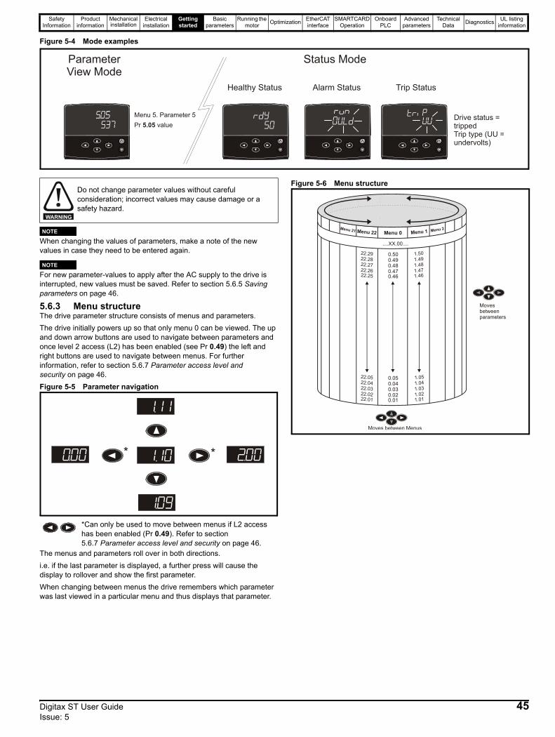
Safety Information
Product information
Mechanical installation
Electrical installation
Getting started
Basic parameters
Running the motor Optimization EtherCAT
interfaceSMARTCARD
OperationOnboard
PLCAdvanced
parametersTechnical
Data Diagnostics UL listing information
Figure 5-4 Mode examples
When changing the values of parameters, make a note of the new values in case they need to be entered again.
For new parameter-values to apply after the AC supply to the drive is interrupted, new values must be saved. Refer to section 5.6.5 Saving parameters on page 46.
5.6.3 Menu structureThe drive parameter structure consists of menus and parameters.The drive initially powers up so that only menu 0 can be viewed. The up and down arrow buttons are used to navigate between parameters and once level 2 access (L2) has been enabled (see Pr 0.49) the left and right buttons are used to navigate between menus. For further information, refer to section 5.6.7 Parameter access level and security on page 46.Figure 5-5 Parameter navigation
The menus and parameters roll over in both directions. i.e. if the last parameter is displayed, a further press will cause the display to rollover and show the first parameter.When changing between menus the drive remembers which parameter was last viewed in a particular menu and thus displays that parameter.
Figure 5-6 Menu structure
Pr value5.05Menu 5. Parameter 5
Parameter View Mode
Healthy Status Alarm Status Trip Status
Status Mode
Drive status = trippedTrip type (UU =undervolts)
Do not change parameter values without careful consideration; incorrect values may cause damage or a safety hazard.
*Can only be used to move between menus if L2 access has been enabled (Pr 0.49). Refer to section 5.6.7 Parameter access level and security on page 46.
WARNING
NOTE
NOTE
* *
Menu 0
....XX.00....
0.500.490.480.470.46
0.010.020.030.040.05
Menu 22 Menu 1 Menu 2Menu 21
22.2922.2822.2722.2622.25
22.0122.0222.0322.0422.05
1.011.021.031.041.05
1.501.491.481.471.46
Movesbetweenparameters
Moves between Menus
Digitax ST User Guide 45Issue: 5
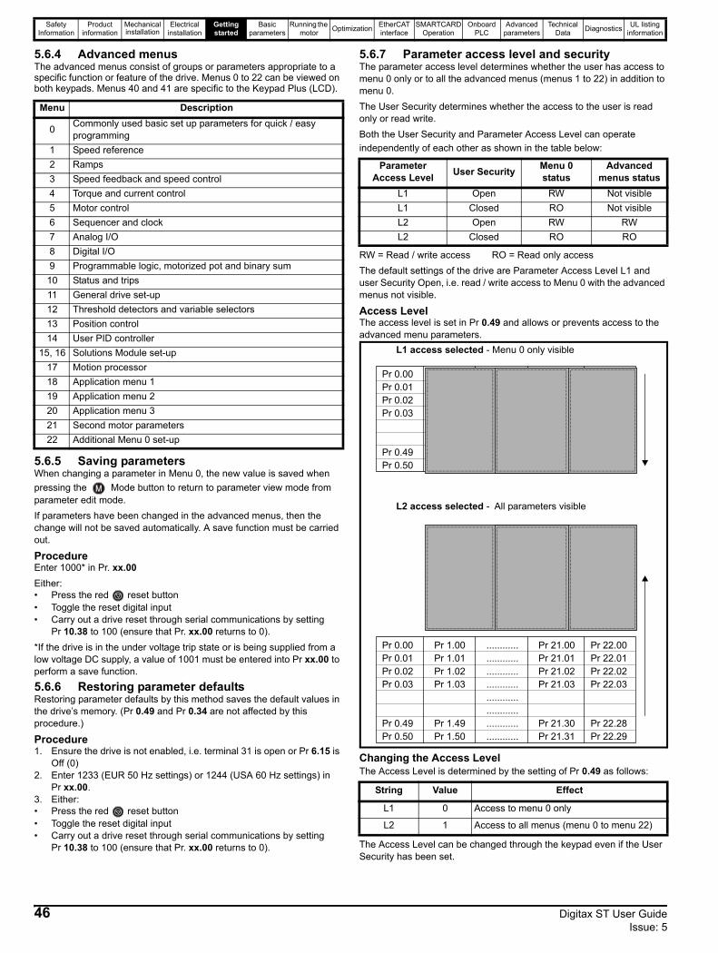
Safety Information
Product information
Mechanical installation
Electrical installation
Getting started
Basic parameters
Running the motor Optimization EtherCAT
interfaceSMARTCARD
OperationOnboard
PLCAdvanced
parametersTechnical
Data Diagnostics UL listing information
5.6.4 Advanced menus The advanced menus consist of groups or parameters appropriate to a specific function or feature of the drive. Menus 0 to 22 can be viewed on both keypads. Menus 40 and 41 are specific to the Keypad Plus (LCD).
5.6.5 Saving parametersWhen changing a parameter in Menu 0, the new value is saved when pressing the Mode button to return to parameter view mode from parameter edit mode.If parameters have been changed in the advanced menus, then the change will not be saved automatically. A save function must be carried out.
ProcedureEnter 1000* in Pr. xx.00Either:• Press the red reset button • Toggle the reset digital input• Carry out a drive reset through serial communications by setting
Pr 10.38 to 100 (ensure that Pr. xx.00 returns to 0).*If the drive is in the under voltage trip state or is being supplied from a low voltage DC supply, a value of 1001 must be entered into Pr xx.00 to perform a save function.
5.6.6 Restoring parameter defaultsRestoring parameter defaults by this method saves the default values in the drive’s memory. (Pr 0.49 and Pr 0.34 are not affected by this procedure.)
Procedure1. Ensure the drive is not enabled, i.e. terminal 31 is open or Pr 6.15 is
Off (0)2. Enter 1233 (EUR 50 Hz settings) or 1244 (USA 60 Hz settings) in
Pr xx.00.3. Either:• Press the red reset button • Toggle the reset digital input• Carry out a drive reset through serial communications by setting
Pr 10.38 to 100 (ensure that Pr. xx.00 returns to 0).
5.6.7 Parameter access level and securityThe parameter access level determines whether the user has access to menu 0 only or to all the advanced menus (menus 1 to 22) in addition to menu 0.The User Security determines whether the access to the user is read only or read write.Both the User Security and Parameter Access Level can operate independently of each other as shown in the table below:
RW = Read / write access RO = Read only accessThe default settings of the drive are Parameter Access Level L1 and user Security Open, i.e. read / write access to Menu 0 with the advanced menus not visible.
Access LevelThe access level is set in Pr 0.49 and allows or prevents access to the advanced menu parameters.
Changing the Access LevelThe Access Level is determined by the setting of Pr 0.49 as follows:
The Access Level can be changed through the keypad even if the User Security has been set.
Menu Description
0 Commonly used basic set up parameters for quick / easy programming
1 Speed reference2 Ramps3 Speed feedback and speed control4 Torque and current control5 Motor control 6 Sequencer and clock7 Analog I/O8 Digital I/O9 Programmable logic, motorized pot and binary sum
10 Status and trips11 General drive set-up12 Threshold detectors and variable selectors13 Position control14 User PID controller
15, 16 Solutions Module set-up17 Motion processor18 Application menu 119 Application menu 220 Application menu 321 Second motor parameters22 Additional Menu 0 set-up
Parameter Access Level User Security Menu 0
statusAdvanced
menus statusL1 Open RW Not visibleL1 Closed RO Not visibleL2 Open RW RWL2 Closed RO RO
String Value Effect
L1 0 Access to menu 0 only
L2 1 Access to all menus (menu 0 to menu 22)
Pr 0.00Pr 0.01Pr 0.02Pr 0.03
Pr 0.49Pr 0.50
Pr 1.00Pr 1.01Pr 1.02Pr 1.03
Pr 1.49Pr 1.50
Pr 22.00Pr 22.01Pr 22.02Pr 22.03
Pr 22.28Pr 22.29
............
............
............
............
............
............
............
............
L2 access selected - All parameters visible
Pr 0.00Pr 0.01Pr 0.02Pr 0.03
Pr 0.49Pr 0.50
Pr 1.00Pr 1.01Pr 1.02Pr 1.03
Pr 1.49Pr 1.50
Pr 19.00Pr 19.01Pr 19.02Pr 19.03
Pr 19.49Pr 19.50
Pr 20.00Pr 20.01Pr 20.02Pr 20.03
Pr 20.49Pr 20.50
............
............
............
............
............
............
............
............
L1 access selected - Menu 0 only visible
Pr 21.00Pr 21.01Pr 21.02Pr 21.03
Pr 21.30Pr 21.31
46 Digitax ST User Guide Issue: 5

Safety Information
Product information
Mechanical installation
Electrical installation
Getting started
Basic parameters
Running the motor Optimization EtherCAT
interfaceSMARTCARD
OperationOnboard
PLCAdvanced
parametersTechnical
Data Diagnostics UL listing information
5.6.8 User SecurityThe User Security, when set, prevents write access to any of the parameters (other than Pr. 0.49 and Pr 11.44 Access Level) in any menu.
Setting User SecurityEnter a value between 1 and 999 in Pr 0.34 and press the button; the security code has now been set to this value. In order to activate the security, the Access level must be set to Loc in Pr 0.49. When the drive is reset, the security code will have been activated and the drive returns to Access Level L1. The value of Pr 0.34 will return to 0 in order to hide the security code. At this point, the only parameter that can be changed by the user is the Access Level Pr 0.49.
Unlocking User SecuritySelect a read write parameter to be edited and press the button, the display will now show CodE. Use the arrow buttons to set the security code and press the button.
With the correct security code entered, the display will revert to the parameter selected in edit mode.If an incorrect security code is entered the display will revert to parameter view mode.
To lock the User Security again, set Pr 0.49 to Loc and press the reset button.
Disabling User SecurityUnlock the previously set security code as detailed above. Set Pr 0.34 to 0 and press the button. The User Security has now been disabled, and will not have to be unlocked each time the drive is powered up to allow read / write access to the parameters.
5.7 Displaying parameters with non-default values only
By entering 12000 in Pr xx.00, the only parameters that will be visible to the user will be those containing a non-default value. This function does not require a drive reset to become active. In order to deactivate this function, return to Pr xx.00 and enter a value of 0.Please note that this function can be affected by the access level enabled, refer to section 5.6.7 Parameter access level and security for further information regarding access level.
5.8 Displaying destination parameters onlyBy entering 12001 in Pr xx.00, the only parameters that will be visible to the user will be destination parameters. This function does not require a drive reset to become active. In order to deactivate this function, return to Pr xx.00 and enter a value of 0.Please note that this function can be affected by the access level enabled, refer to section 5.6.7 Parameter access level and security for further information regarding access level.
5.9 Communications5.9.1 IntroductionThe Digitax ST has a standard 2-wire EIA485 interface (serial communications interface) which enables all drive set-up, operation and monitoring to be carried out with a PC or PLC if required. Therefore, it is possible to control the drive entirely by serial communications without the need for a -keypad or other control cabling. The Digitax ST supports two protocols selected by parameter configuration:• Modbus RTU• CT ANSIModbus RTU has been set as the default protocol, as it is used with the PC-tools set-up software as provided on the CD ROM.The communications port of the drive is a RJ45 socket, and is isolated from the power stage and the other control terminals. The communications port applies a 2 unit load to the communications network.USB/EIA232 to EIA485 CommunicationsAn external USB/EIA232 hardware interface such as a PC cannot be used directly with the 2-wire interface of the drive. Therefore a suitable converter is required.Suitable USB to EIA485 and EIA232 to EIA485 isolated converters are available from Emerson Industrial Automation as follows:• CT USB Comms cable (CT Part No. 4500-0096)• CT EIA232 Comms cable (CT Part No. 4500-0087)When using one of the above converters or any other suitable converter with the Digitax ST, it is recommended that no terminating resistors be connected on the network. It may be necessary to 'jumper out' the terminating resistor within the converter depending on which type is used. The information on how to jumper out the terminating resistor will normally be contained in the user information supplied with the converter.
Pr 0.00Pr 0.01Pr 0.02Pr 0.03
Pr 0.50
Pr 1.00Pr 1.01Pr 1.02Pr 1.03
Pr 1.49Pr 1.50
............
............
............
............
............
............
............
............
Pr 0.00Pr 0.01Pr 0.02Pr 0.03
Pr 0.49Pr 0.50
Pr 1.00Pr 1.01Pr 1.02Pr 1.03
Pr 1.49Pr 1.50
Pr 22.00Pr 22.01Pr 22.02Pr 22.03
Pr 22.28Pr 22.29
............
............
............
............
............
............
............
............
User security open - All parameters: Read / Write access
User security closed0.49 11.44
- All parameters: Read Only access (except Pr and Pr )
Pr 22.00Pr 22.01Pr 22.02Pr 22.03
Pr 22.28Pr 22.29
Pr 0.49
Pr 21.00Pr 21.01Pr 21.02Pr 21.03
Pr 21.30Pr 21.31
Pr 21.00Pr 21.01Pr 21.02Pr 21.03
Pr 21.30Pr 21.31
Digitax ST User Guide 47Issue: 5

Safety Information
Product information
Mechanical installation
Electrical installation
Getting started
Basic parameters
Running the motor Optimization EtherCAT
interfaceSMARTCARD
OperationOnboard
PLCAdvanced
parametersTechnical
Data Diagnostics UL listing information
5.9.2 Communications set-up parametersThe following parameters need to be set according to the system requirements.
This parameter defines the communications protocol used by the 485 comms port on the drive. This parameter can be changed via the drive keypad, via a Solutions Module or via the comms interface itself. If it is changed via the comms interface, the response to the command uses the original protocol. The master should wait at least 20ms before send a new message using the new protocol. (Note: ANSI uses 7 data bits, 1 stop bit and even parity; Modbus RTU uses 8 data bits, 2 stops bits and no parity.)
ANSIx3.28 protocolFull details of the CT ANSI communications protocol are given in the Advanced User Guide.Modbus RTU protocolFull details of the CT implementation of Modbus RTU are given in the Advanced User Guide.Modbus RTU protocol, but with an SM-Keypad Plus onlyThis setting is used for disabling communications access when the -Keypad Plus is used as a hardware key. See the Advanced User Guide for more details.
* only applicable to Modbus RTU modeThis parameter can be changed via the drive keypad, via a Solutions Module or via the comms interface itself. If it is changed via the comms interface, the response to the command uses the original baud rate. The master should wait at least 20 ms before sending a new message using the new baud rate.
When using the CT EIA232 Comms cable the available baud rate is limited to 19.2 k baud.
Used to define the unique address for the drive for the serial interface. The drive is always a slave. Modbus RTU When the Modbus RTU protocol is used addresses between 0 and 247 are permitted. Address 0 is used to globally address all slaves, and so this address should not be set in this parameterANSIWhen the ANSI protocol is used the first digit is the group and the second digit is the address within a group. The maximum permitted group number is 9 and the maximum permitted address within a group is
9. Therefore, Pr 0.37 is limited to 99 in this mode. The value 00 is used to globally address all slaves on the system, and x0 is used to address all slaves of group x, therefore these addresses should not be set in this parameter.
0.35 {11.24} Serial modeRW Txt US
AnSI (0)rtU (1) rtU (1)
Comms value String Communications mode0 AnSI ANSI1 rtU Modbus RTU protocol
2 Lcd Modbus RTU protocol, but with an Keypad Plus only
0.36 {11.25} Serial communications baud rateRW Txt US
300 (0), 600 (1), 1200 (2), 2400 (3), 4800 (4), 9600 (5),
19200 (6), 38400 (7), 57600 (8)*, 115200 (9)*
19200 (6)
0.37 {11.23} Serial communications addressRW Txt US
0 to 247 1
NOTE
48 Digitax ST User Guide Issue: 5
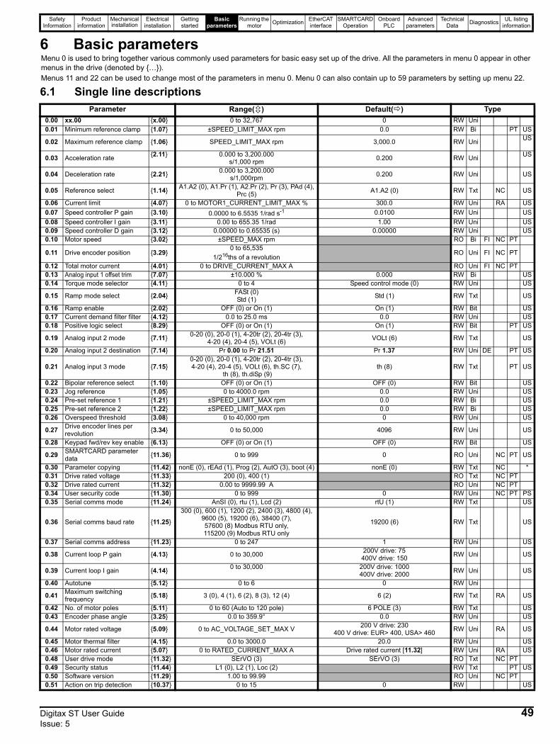
Safety Information
Product information
Mechanical installation
Electrical installation
Getting started
Basic parameters
Running the motor Optimization EtherCAT
interfaceSMARTCARD
OperationOnboard
PLCAdvanced
parametersTechnical
Data Diagnostics UL listing information
6 Basic parameters
6.1 Single line descriptions
Menu 0 is used to bring together various commonly used parameters for basic easy set up of the drive. All the parameters in menu 0 appear in other menus in the drive (denoted by {…}). Menus 11 and 22 can be used to change most of the parameters in menu 0. Menu 0 can also contain up to 59 parameters by setting up menu 22.
Parameter Range( ) Default( ) Type0.00 xx.00 {x.00} 0 to 32,767 0 RW Uni0.01 Minimum reference clamp {1.07} ±SPEED_LIMIT_MAX rpm 0.0 RW Bi PT US
0.02 Maximum reference clamp {1.06} SPEED_LIMIT_MAX rpm 3,000.0 RW Uni US
0.03 Acceleration rate {2.11} 0.000 to 3,200.000 s/1,000 rpm 0.200 RW Uni US
0.04 Deceleration rate {2.21} 0.000 to 3,200.000s/1,000rpm 0.200 RW Uni US
0.05 Reference select {1.14} A1.A2 (0), A1.Pr (1), A2.Pr (2), Pr (3), PAd (4), Prc (5) A1.A2 (0) RW Txt NC US
0.06 Current limit {4.07} 0 to MOTOR1_CURRENT_LIMIT_MAX % 300.0 RW Uni RA US0.07 Speed controller P gain {3.10} 0.0000 to 6.5535 1/rad s-1 0.0100 RW Uni US0.08 Speed controller I gain {3.11} 0.00 to 655.35 1/rad 1.00 RW Uni US0.09 Speed controller D gain {3.12} 0.00000 to 0.65535 (s) 0.00000 RW Uni US0.10 Motor speed {3.02} ±SPEED_MAX rpm RO Bi FI NC PT
0.11 Drive encoder position {3.29}0 to 65,535
1/216ths of a revolutionRO Uni FI NC PT
0.12 Total motor current {4.01} 0 to DRIVE_CURRENT_MAX A RO Uni FI NC PT0.13 Analog input 1 offset trim {7.07} ±10.000 % 0.000 RW Bi US0.14 Torque mode selector {4.11} 0 to 4 Speed control mode (0) RW Uni US
0.15 Ramp mode select {2.04} FASt (0)Std (1) Std (1) RW Txt US
0.16 Ramp enable {2.02} OFF (0) or On (1) On (1) RW Bit US0.17 Current demand filter filter {4.12} 0.0 to 25.0 ms 0.0 RW Uni US0.18 Positive logic select {8.29} OFF (0) or On (1) On (1) RW Bit PT US
0.19 Analog input 2 mode {7.11} 0-20 (0), 20-0 (1), 4-20tr (2), 20-4tr (3), 4-20 (4), 20-4 (5), VOLt (6) VOLt (6) RW Txt US
0.20 Analog input 2 destination {7.14} Pr 0.00 to Pr 21.51 Pr 1.37 RW Uni DE PT US
0.21 Analog input 3 mode {7.15}0-20 (0), 20-0 (1), 4-20tr (2), 20-4tr (3), 4-20 (4), 20-4 (5), VOLt (6), th.SC (7),
th (8), th.diSp (9)th (8) RW Txt PT US
0.22 Bipolar reference select {1.10} OFF (0) or On (1) OFF (0) RW Bit US0.23 Jog reference {1.05} 0 to 4000.0 rpm 0.0 RW Uni US0.24 Pre-set reference 1 {1.21} ±SPEED_LIMIT_MAX rpm 0.0 RW Bi US0.25 Pre-set reference 2 {1.22} ±SPEED_LIMIT_MAX rpm 0.0 RW Bi US0.26 Overspeed threshold {3.08} 0 to 40,000 rpm 0 RW Uni US
0.27 Drive encoder lines per revolution {3.34} 0 to 50,000 4096 RW Uni US
0.28 Keypad fwd/rev key enable {6.13} OFF (0) or On (1) OFF (0) RW Bit US
0.29 SMARTCARD parameter data {11.36} 0 to 999 0 RO Uni NC PT US
0.30 Parameter copying {11.42} nonE (0), rEAd (1), Prog (2), AutO (3), boot (4) nonE (0) RW Txt NC *0.31 Drive rated voltage {11.33} 200 (0), 400 (1) RO Txt NC PT0.32 Drive rated current {11.32} 0.00 to 9999.99 A RO Uni NC PT0.34 User security code {11.30} 0 to 999 0 RW Uni NC PT PS0.35 Serial comms mode {11.24} AnSI (0), rtu (1), Lcd (2) rtU (1) RW Txt US
0.36 Serial comms baud rate {11.25}
300 (0), 600 (1), 1200 (2), 2400 (3), 4800 (4), 9600 (5), 19200 (6), 38400 (7), 57600 (8) Modbus RTU only, 115200 (9) Modbus RTU only
19200 (6) RW Txt US
0.37 Serial comms address {11.23} 0 to 247 1 RW Uni US
0.38 Current loop P gain {4.13} 0 to 30,000 200V drive: 75400V drive: 150 RW Uni US
0.39 Current loop I gain {4.14} 0 to 30,000 200V drive: 1000400V drive: 2000 RW Uni US
0.40 Autotune {5.12} 0 to 6 0 RW Uni
0.41 Maximum switching frequency {5.18} 3 (0), 4 (1), 6 (2), 8 (3), 12 (4) 6 (2) RW Txt RA US
0.42 No. of motor poles {5.11} 0 to 60 (Auto to 120 pole) 6 POLE (3) RW Txt US0.43 Encoder phase angle {3.25} 0.0 to 359.9° 0.0 RW Uni US
0.44 Motor rated voltage {5.09} 0 to AC_VOLTAGE_SET_MAX V 200 V drive: 230400 V drive: EUR> 400, USA> 460 RW Uni RA US
0.45 Motor thermal filter {4.15} 0.0 to 3000.0 20.0 RW Uni US0.46 Motor rated current {5.07} 0 to RATED_CURRENT_MAX A Drive rated current [11.32] RW Uni RA US0.48 User drive mode {11.32} SErVO (3) SErVO (3) RO Txt NC PT0.49 Security status {11.44} L1 (0), L2 (1), Loc (2) RW Txt PT US0.50 Software version {11.29} 1.00 to 99.99 RO Uni NC PT0.51 Action on trip detection {10.37} 0 to 15 0 RW US
Digitax ST User Guide 49Issue: 5
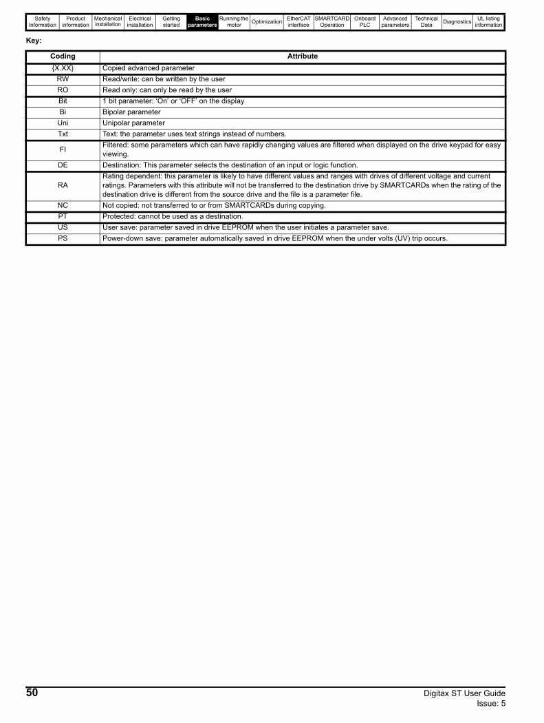
Safety Information
Product information
Mechanical installation
Electrical installation
Getting started
Basic parameters
Running the motor Optimization EtherCAT
interfaceSMARTCARD
OperationOnboard
PLCAdvanced
parametersTechnical
Data Diagnostics UL listing information
Key:
Coding Attribute{X.XX} Copied advanced parameter
RW Read/write: can be written by the userRO Read only: can only be read by the userBit 1 bit parameter: ‘On’ or ‘OFF’ on the displayBi Bipolar parameter
Uni Unipolar parameterTxt Text: the parameter uses text strings instead of numbers.
FI Filtered: some parameters which can have rapidly changing values are filtered when displayed on the drive keypad for easy viewing.
DE Destination: This parameter selects the destination of an input or logic function.
RARating dependent: this parameter is likely to have different values and ranges with drives of different voltage and current ratings. Parameters with this attribute will not be transferred to the destination drive by SMARTCARDs when the rating of the destination drive is different from the source drive and the file is a parameter file.
NC Not copied: not transferred to or from SMARTCARDs during copying.PT Protected: cannot be used as a destination.US User save: parameter saved in drive EEPROM when the user initiates a parameter save.PS Power-down save: parameter automatically saved in drive EEPROM when the under volts (UV) trip occurs.
50 Digitax ST User Guide Issue: 5

Safety Information
Product information
Mechanical installation
Electrical installation
Getting started
Basic parameters
Running the motor Optimization EtherCAT
interfaceSMARTCARD
OperationOnboard
PLCAdvanced
parametersTechnical
Data Diagnostics UL listing information
Digitax ST User Guide 51Issue: 5
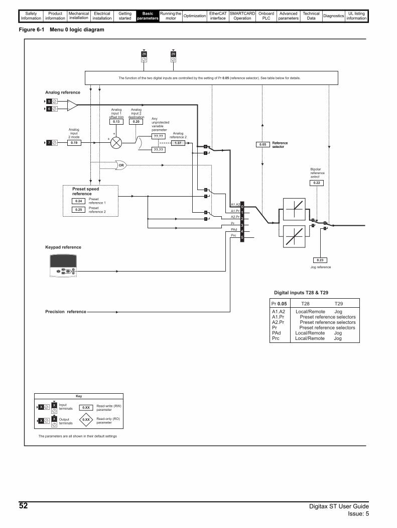
Safety Information
Product information
Mechanical installation
Electrical installation
Getting started
Basic parameters
Running the motor Optimization EtherCAT
interfaceSMARTCARD
OperationOnboard
PLCAdvanced
parametersTechnical
Data Diagnostics UL listing information
Figure 6-1 Menu 0 logic diagram
Analoginput
2 mode
0.19
5
6
7
Analog reference
Keypad reference
0.XX
0.XX
Key
Read-write (RW)parameter
Read-only (RO)parameter
Inputterminals
Outputterminals
XX
XX
The parameters are all shown in their default settings
0.24
0.25
Presetreference 1
Presetreference 2
Preset speedreference
Analogreference 2
1.37+
+
0.20
??.??
Anyunprotectedvariableparameter
??.??
Analoginput 2
destination
0.13
28 29
The function of the two digital inputs are controlled by the setting of Pr (reference selector). See table below for details.0.05
0
1
2
3
4
5
OR
Precision reference
0.05 Referenceselector
Analoginput 1
offset trim
0.05 Referenceselector
0.22
Bipolarreferenceselect
0.23
Jog reference
A1.A2 Local/Remote JogA1.Pr Preset reference selectorsA2.Pr Preset reference selectorsPr Preset reference selectorsPAd Local/Remote JogPrc Local/Remote Jog
Pr T28 T290.05
Digital inputs T28 & T29
A1.A2
A1.Pr
A2.Pr
Pr
PAd
Prc
52 Digitax ST User Guide Issue: 5
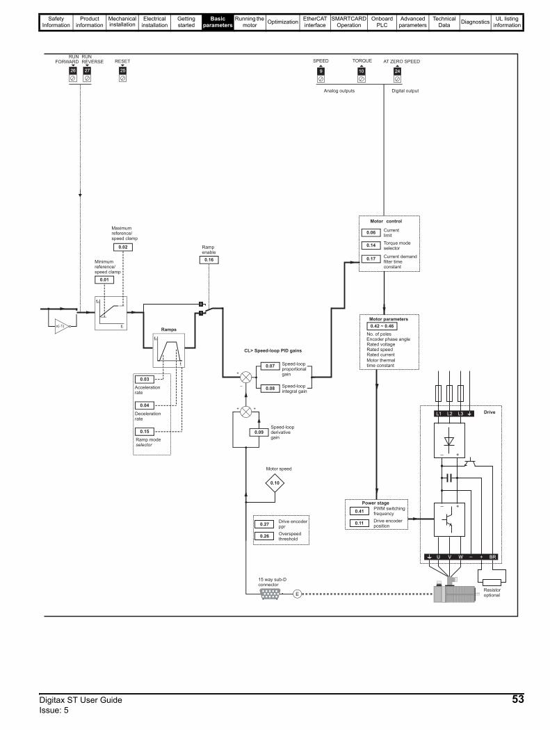
Safety Information
Product information
Mechanical installation
Electrical installation
Getting started
Basic parameters
Running the motor Optimization EtherCAT
interfaceSMARTCARD
OperationOnboard
PLCAdvanced
parametersTechnical
Data Diagnostics UL listing information
SPEED TORQUE
Motor control
Speed-loopproportionalgain
Motor speed
0.06
0.07
Speed-loopintegral gain
0.08
Speed-loopderivativegain
0.09
0.10
CL> Speed-loop PID gains
9 10
15 way sub-Dconnector
24
AT ZERO SPEED
Currentlimit
No. of poles
Rated voltageRated speedRated current
0.42 ~ 0.46
Motor parameters
Power stage _ +
L1 L2 L3
_ +
U V W
Resistoroptional
Drive
RUNFORWARD
RUNREVERSE RESET
Minimumreference/speed clamp
0.01
0.02
26 27 25
Ramps
Accelerationrate
Decelerationrate
Ramp modeselector
0.03
0.04
0.15
0.16
Maximumreference/speed clamp
Rampenable
Analog outputs Digital output
0.27
0.26
Drive encoderppr
Overspeedthreshold
0.41
0.11
PWM switchingfrequency
Drive encoderposition
Motor thermaltime constant
0.14Torque modeselector
0.17Current demandfilter timeconstant
+ BR_
Encoder phase angle
Digitax ST User Guide 53Issue: 5
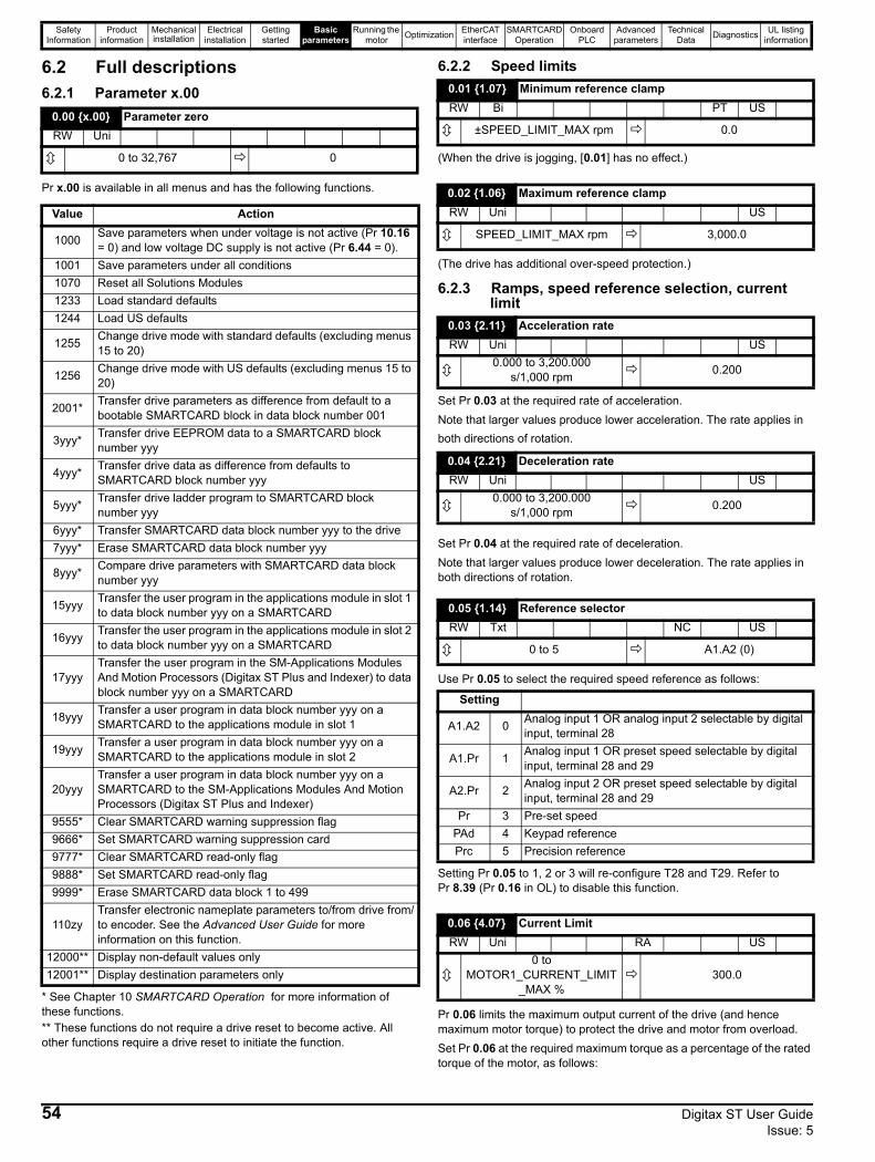
Safety Information
Product information
Mechanical installation
Electrical installation
Getting started
Basic parameters
Running the motor Optimization EtherCAT
interfaceSMARTCARD
OperationOnboard
PLCAdvanced
parametersTechnical
Data Diagnostics UL listing information
6.2 Full descriptions6.2.1 Parameter x.00
Pr x.00 is available in all menus and has the following functions.
* See Chapter 10 SMARTCARD Operation for more information of these functions.** These functions do not require a drive reset to become active. All other functions require a drive reset to initiate the function.
6.2.2 Speed limits
(When the drive is jogging, [0.01] has no effect.)
(The drive has additional over-speed protection.)
6.2.3 Ramps, speed reference selection, current limit
Set Pr 0.03 at the required rate of acceleration.Note that larger values produce lower acceleration. The rate applies in both directions of rotation.
Set Pr 0.04 at the required rate of deceleration.Note that larger values produce lower deceleration. The rate applies in both directions of rotation.
Use Pr 0.05 to select the required speed reference as follows:
Setting Pr 0.05 to 1, 2 or 3 will re-configure T28 and T29. Refer to Pr 8.39 (Pr 0.16 in OL) to disable this function.
Pr 0.06 limits the maximum output current of the drive (and hence maximum motor torque) to protect the drive and motor from overload.Set Pr 0.06 at the required maximum torque as a percentage of the rated torque of the motor, as follows:
0.00 {x.00} Parameter zeroRW Uni
0 to 32,767 0
Value Action
1000 Save parameters when under voltage is not active (Pr 10.16 = 0) and low voltage DC supply is not active (Pr 6.44 = 0).
1001 Save parameters under all conditions1070 Reset all Solutions Modules1233 Load standard defaults1244 Load US defaults
1255 Change drive mode with standard defaults (excluding menus 15 to 20)
1256 Change drive mode with US defaults (excluding menus 15 to 20)
2001* Transfer drive parameters as difference from default to a bootable SMARTCARD block in data block number 001
3yyy* Transfer drive EEPROM data to a SMARTCARD block number yyy
4yyy* Transfer drive data as difference from defaults to SMARTCARD block number yyy
5yyy* Transfer drive ladder program to SMARTCARD block number yyy
6yyy* Transfer SMARTCARD data block number yyy to the drive7yyy* Erase SMARTCARD data block number yyy
8yyy* Compare drive parameters with SMARTCARD data block number yyy
15yyy Transfer the user program in the applications module in slot 1 to data block number yyy on a SMARTCARD
16yyy Transfer the user program in the applications module in slot 2 to data block number yyy on a SMARTCARD
17yyyTransfer the user program in the SM-Applications Modules And Motion Processors (Digitax ST Plus and Indexer) to data block number yyy on a SMARTCARD
18yyy Transfer a user program in data block number yyy on a SMARTCARD to the applications module in slot 1
19yyy Transfer a user program in data block number yyy on a SMARTCARD to the applications module in slot 2
20yyyTransfer a user program in data block number yyy on a SMARTCARD to the SM-Applications Modules And Motion Processors (Digitax ST Plus and Indexer)
9555* Clear SMARTCARD warning suppression flag9666* Set SMARTCARD warning suppression card9777* Clear SMARTCARD read-only flag9888* Set SMARTCARD read-only flag9999* Erase SMARTCARD data block 1 to 499
110zyTransfer electronic nameplate parameters to/from drive from/to encoder. See the Advanced User Guide for more information on this function.
12000** Display non-default values only12001** Display destination parameters only
0.01 {1.07} Minimum reference clampRW Bi PT US
±SPEED_LIMIT_MAX rpm 0.0
0.02 {1.06} Maximum reference clampRW Uni US
SPEED_LIMIT_MAX rpm 3,000.0
0.03 {2.11} Acceleration rateRW Uni US
0.000 to 3,200.000 s/1,000 rpm 0.200
0.04 {2.21} Deceleration rateRW Uni US
0.000 to 3,200.000 s/1,000 rpm 0.200
0.05 {1.14} Reference selectorRW Txt NC US
0 to 5 A1.A2 (0)
Setting
A1.A2 0 Analog input 1 OR analog input 2 selectable by digital input, terminal 28
A1.Pr 1 Analog input 1 OR preset speed selectable by digital input, terminal 28 and 29
A2.Pr 2 Analog input 2 OR preset speed selectable by digital input, terminal 28 and 29
Pr 3 Pre-set speedPAd 4 Keypad referencePrc 5 Precision reference
0.06 {4.07} Current LimitRW Uni RA US
0 to MOTOR1_CURRENT_LIMIT
_MAX %300.0
54 Digitax ST User Guide Issue: 5
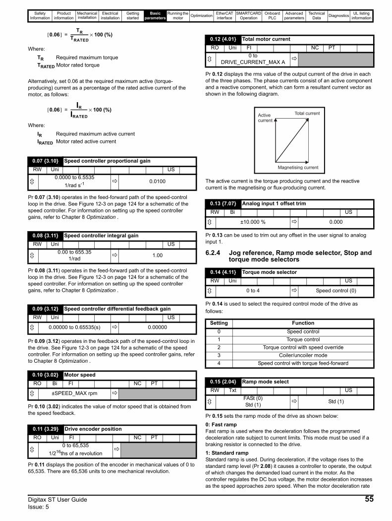
Safety Information
Product information
Mechanical installation
Electrical installation
Getting started
Basic parameters
Running the motor Optimization EtherCAT
interfaceSMARTCARD
OperationOnboard
PLCAdvanced
parametersTechnical
Data Diagnostics UL listing information
(%)
Where:TR Required maximum torqueTRATED Motor rated torque
Alternatively, set 0.06 at the required maximum active (torque-producing) current as a percentage of the rated active current of the motor, as follows:
(%)
Where:IR Required maximum active currentIRATED Motor rated active current
Pr 0.07 (3.10) operates in the feed-forward path of the speed-control loop in the drive. See Figure 12-3 on page 124 for a schematic of the speed controller. For information on setting up the speed controller gains, refer to Chapter 8 Optimization .
Pr 0.08 (3.11) operates in the feed-forward path of the speed-control loop in the drive. See Figure 12-3 on page 124 for a schematic of the speed controller. For information on setting up the speed controller gains, refer to Chapter 8 Optimization .
Pr 0.09 (3.12) operates in the feedback path of the speed-control loop in the drive. See Figure 12-3 on page 124 for a schematic of the speed controller. For information on setting up the speed controller gains, refer to Chapter 8 Optimization .
Pr 0.10 (3.02) indicates the value of motor speed that is obtained from the speed feedback.
Pr 0.11 displays the position of the encoder in mechanical values of 0 to 65,535. There are 65,536 units to one mechanical revolution.
Pr 0.12 displays the rms value of the output current of the drive in each of the three phases. The phase currents consist of an active component and a reactive component, which can form a resultant current vector as shown in the following diagram.
The active current is the torque producing current and the reactive current is the magnetising or flux-producing current.
Pr 0.13 can be used to trim out any offset in the user signal to analog input 1.
6.2.4 Jog reference, Ramp mode selector, Stop and torque mode selectors
Pr 0.14 is used to select the required control mode of the drive as follows:
Pr 0.15 sets the ramp mode of the drive as shown below:0: Fast rampFast ramp is used where the deceleration follows the programmed deceleration rate subject to current limits. This mode must be used if a braking resistor is connected to the drive.1: Standard rampStandard ramp is used. During deceleration, if the voltage rises to the standard ramp level (Pr 2.08) it causes a controller to operate, the output of which changes the demanded load current in the motor. As the controller regulates the DC bus voltage, the motor deceleration increases as the speed approaches zero speed. When the motor deceleration rate
0.07 {3.10} Speed controller proportional gainRW Uni US
0.0000 to 6.55351/rad s-1 0.0100
0.08 {3.11} Speed controller integral gainRW Uni US
0.00 to 655.351/rad 1.00
0.09 {3.12} Speed controller differential feedback gain RW Uni US
0.00000 to 0.65535(s) 0.00000
0.10 {3.02} Motor speedRO Bi FI NC PT
±SPEED_MAX rpm
0.11 {3.29} Drive encoder positionRO Uni FI NC PT
0 to 65,535 1/216ths of a revolution
0.06[ ]TR
TRATED-------------------- 100×=
0.06[ ]IR
IRATED------------------- 100×=
0.12 {4.01} Total motor currentRO Uni FI NC PT
0 to DRIVE_CURRENT_MAX A
0.13 {7.07} Analog input 1 offset trimRW Bi US
±10.000 % 0.000
0.14 {4.11} Torque mode selectorRW Uni US
0 to 4 Speed control (0)
Setting Function0 Speed control1 Torque control2 Torque control with speed override3 Coiler/uncoiler mode4 Speed control with torque feed-forward
0.15 {2.04} Ramp mode selectRW Txt US
FASt (0)Std (1) Std (1)
Activecurrent
Total current
Magnetising current
Digitax ST User Guide 55Issue: 5
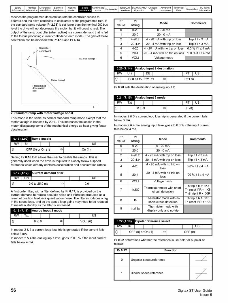
Safety Information
Product information
Mechanical installation
Electrical installation
Getting started
Basic parameters
Running the motor Optimization EtherCAT
interfaceSMARTCARD
OperationOnboard
PLCAdvanced
parametersTechnical
Data Diagnostics UL listing information
reaches the programmed deceleration rate the controller ceases to operate and the drive continues to decelerate at the programmed rate. If the standard ramp voltage (Pr 2.08) is set lower than the nominal DC bus level the drive will not decelerate the motor, but it will coast to rest. The output of the ramp controller (when active) is a current demand that is fed to the torque producing current controller (Servo mode). The gain of these controllers can be modified with Pr 4.13 and Pr 4.14.
2: Standard ramp with motor voltage boostThis mode is the same as normal standard ramp mode except that the motor voltage is boosted by 20 %. This increases the losses in the motor, dissipating some of the mechanical energy as heat giving faster deceleration.
Setting Pr 0.16 to 0 allows the user to disable the ramps. This is generally used when the drive is required to closely follow a speed reference which already contains acceleration and deceleration ramps.
A first order filter, with a filter defined by Pr 0.17, is provided on the current demand to reduce acoustic noise and vibration produced as a result of position feedback quantization noise. The filter introduces a lag in the speed loop, and so the speed loop gains may need to be reduced to maintain stability as the filter is increased.
In modes 2 & 3 a current loop loss trip is generated if the current falls below 3 mA.In modes 2 & 4 the analog input level goes to 0.0 % if the input current falls below 4 mA.
Pr 0.20 sets the destination of analog input 2.
In modes 2 & 3 a current loop loss trip is generated if the current falls below 3 mA.In modes 2 & 4 the analog input level goes to 0.0 % if the input current falls below 4 mA.
Pr 0.22 determines whether the reference is uni-polar or bi-polar as follows:
0.16 {2.02} Ramp enableRW Bit US
OFF (0) or On (1) On (1)
0.17 {4.12} Current demand filterRW Uni US
0.0 to 25.0 ms 0.0
0.19 {7.11} Analog input 2 modeRW Txt US
0 to 6 VOLt (6)
DC bus voltage
Motor Speed
Programmeddecelerationrate
t
Controlleroperational
Pr value
Pr string Mode Comments
0 0-20 0 - 20 mA1 20-0 20 - 0 mA2 4-20.tr 4 - 20 mA with trip on loss Trip if I < 3 mA3 20-4.tr 20 - 4 mA with trip on loss Trip if I < 3 mA4 4-20 4 - 20 mA with no trip on loss 0.0 % if I ≤ 4 mA5 20-4 20 – 4 mA with no trip on loss 100 % if I ≤ 4 mA6 VOLt Voltage mode
0.20 {7.14} Analog input 2 destinationRW Uni DE PT US
Pr 0.00 to Pr 21.51 Pr 1.37
0.21 {7.15} Analog input 3 modeRW Txt PT US
0 to 9 th (8)
Pr value
Pr string Mode Comments
0 0-20 0 - 20 mA1 20-0 20 - 0 mA2 4-20.tr 4 - 20 mA with trip on loss Trip if I < 3 mA3 20-4.tr 20 - 4 mA with trip on loss Trip if I < 3 mA
4 4-20 4 - 20 mA with no trip on loss 0.0% if I ≤ 4 mA
5 20-4 20 - 4 mA with no trip on loss 100 % if I ≤ 4 mA
6 VOLt Voltage mode
7 th.SC Thermistor mode with short-circuit detection
Th trip if R > 3K3Th reset if R < 1K8ThS trip if R < 50R
8 th Thermistor mode with no short-circuit detection
Th trip if R > 3K3Th reset if R < 1K8
9 th.diSp Thermistor mode with display only and no trip
0.22 {1.10} Bipolar reference selectRW Bit US
OFF (0) or On (1) OFF (0)
Pr 0.22 Function
0 Unipolar speed/reference
1 Bipolar speed/reference
56 Digitax ST User Guide Issue: 5
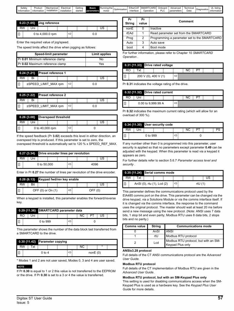
Safety Information
Product information
Mechanical installation
Electrical installation
Getting started
Basic parameters
Running the motor Optimization EtherCAT
interfaceSMARTCARD
OperationOnboard
PLCAdvanced
parametersTechnical
Data Diagnostics UL listing information
Enter the required value of jog/speed. The speed limits affect the drive when jogging as follows:
If the speed feedback (Pr 3.02) exceeds this level in either direction, an overspeed trip is produced. If this parameter is set to zero, the overspeed threshold is automatically set to 120 % x SPEED_REF_MAX.
Enter in Pr 0.27 the number of lines per revolution of the drive encoder.
When a keypad is installed, this parameter enables the forward/reverse key.
This parameter shows the number of the data block last transferred from a SMARTCARD to the drive.
* Modes 1 and 2 are not user saved, Modes 0, 3 and 4 are user saved.
NIf Pr 0.30 is equal to 1 or 2 this value is not transferred to the EEPROM or the drive. If Pr 0.30 is set to a 3 or 4 the value is transferred.
For further information, please refer to Chapter 10 SMARTCARD Operation .
Pr 0.31 indicates the voltage rating of the drive.
Pr 0.32 indicates the maximum current rating (which will allow for an overload of 300 %).
If any number other than 0 is programmed into this parameter, user security is applied so that no parameters except parameter 0.49 can be adjusted with the keypad. When this parameter is read via a keypad it appears as zero.For further details refer to section 5.6.7 Parameter access level and security .
This parameter defines the communications protocol used by the EIA485 comms port on the drive. This parameter can be changed via the drive keypad, via a Solutions Module or via the comms interface itself. If it is changed via the comms interface, the response to the command uses the original protocol. The master should wait at least 20 ms before send a new message using the new protocol. (Note: ANSI uses 7 data bits, 1 stop bit and even parity; Modbus RTU uses 8 data bits, 2 stops bits and no parity.)
ANSIx3.28 protocolFull details of the CT ANSI communications protocol are the Advanced User Guide.Modbus RTU protocolFull details of the CT implementation of Modbus RTU are given in the Advanced User Guide.Modbus RTU protocol, but with an SM-Keypad Plus onlyThis setting is used for disabling communications access when the SM-Keypad Plus is used as a hardware key. See the Keypad Plus User Guide for more details.
0.23 {1.05} Jog referenceRW Uni US
0 to 4,000.0 rpm 0.0
Speed-limit parameter Limit appliesPr 0.01 Minimum reference clamp NoPr 0.02 Maximum reference clamp Yes
0.24 {1.21} Preset reference 1RW Bi US
±SPEED_LIMIT_MAX rpm 0.0
0.25 {1.22} Preset reference 2RW Bi US
±SPEED_LIMIT_MAX rpm 0.0
0.26 {3.08} Overspeed thresholdRW Uni US
0 to 40,000 rpm 0
0.27 {3.34} Drive encoder lines per revolutionRW Uni US
0 to 50,000 4096
0.28 {6.13} Keypad fwd/rev key enableRW Bit US
OFF (0) or On (1) OFF (0)
0.29 {11.36} SMARTCARD parameter dataRO Uni NC PT US
0 to 999 0
0.30 {11.42} Parameter copyingRW Txt NC *
0 to 4 nonE (0)
NOTE
Pr String
Pr value Comment
nonE 0 InactiverEAd 1 Read parameter set from the SMARTCARDProg 2 Programming a parameter set to the SMARTCARDAuto 3 Auto saveboot 4 Boot mode
0.31 {11.33} Drive rated voltageRO Txt NC PT
200 V (0), 400 V (1)
0.32 {11.32} Drive rated currentRO Uni NC PT
0.00 to 9,999.99 A
0.34 {11.30} User security codeRW Uni NC PT PS
0 to 999 0
0.35 {11.24} Serial comms modeRW Txt US
AnSI (0), rtu (1), Lcd (2) rtU (1)
Comms value String Communications mode0 AnSI ANSI1 rtU Modbus RTU protocol
2 Lcd Modbus RTU protocol, but with an SM-Keypad Plus only
Digitax ST User Guide 57Issue: 5
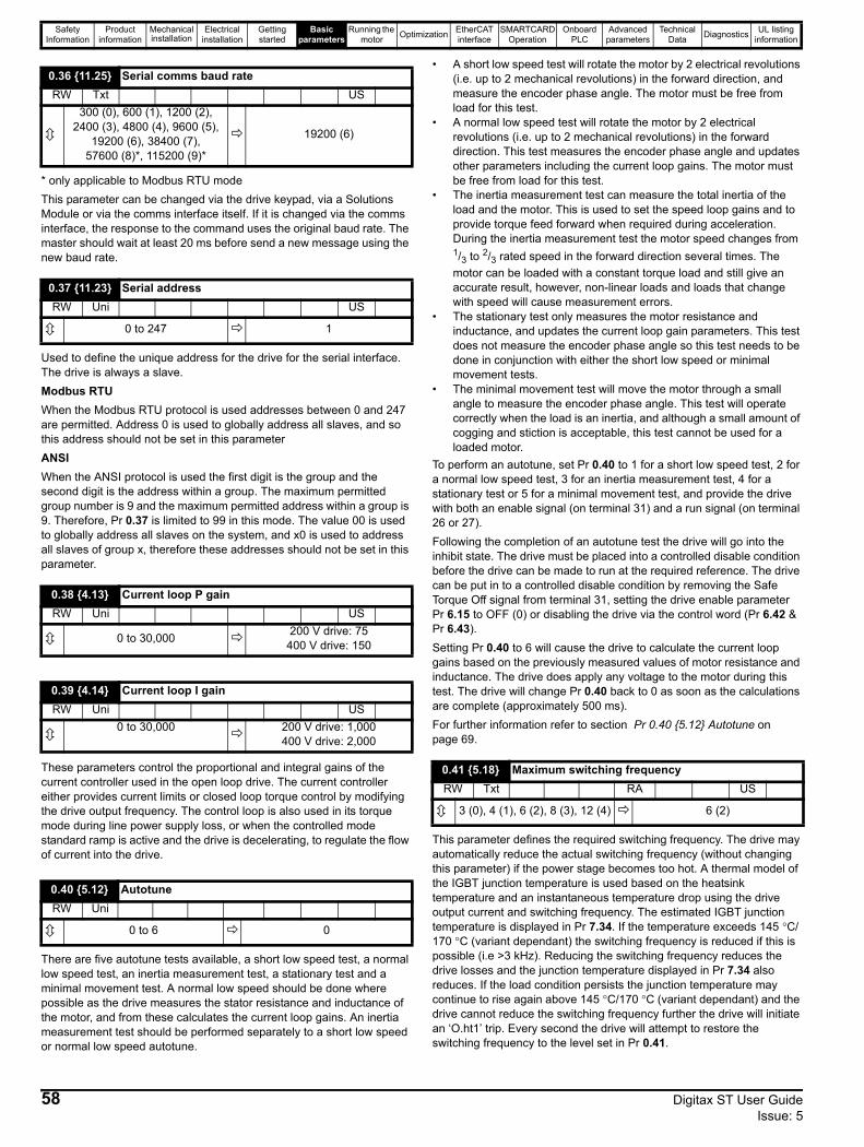
Safety Information
Product information
Mechanical installation
Electrical installation
Getting started
Basic parameters
Running the motor Optimization EtherCAT
interfaceSMARTCARD
OperationOnboard
PLCAdvanced
parametersTechnical
Data Diagnostics UL listing information
* only applicable to Modbus RTU modeThis parameter can be changed via the drive keypad, via a Solutions Module or via the comms interface itself. If it is changed via the comms interface, the response to the command uses the original baud rate. The master should wait at least 20 ms before send a new message using the new baud rate.
Used to define the unique address for the drive for the serial interface. The drive is always a slave. Modbus RTU When the Modbus RTU protocol is used addresses between 0 and 247 are permitted. Address 0 is used to globally address all slaves, and so this address should not be set in this parameterANSIWhen the ANSI protocol is used the first digit is the group and the second digit is the address within a group. The maximum permitted group number is 9 and the maximum permitted address within a group is 9. Therefore, Pr 0.37 is limited to 99 in this mode. The value 00 is used to globally address all slaves on the system, and x0 is used to address all slaves of group x, therefore these addresses should not be set in this parameter.
These parameters control the proportional and integral gains of the current controller used in the open loop drive. The current controller either provides current limits or closed loop torque control by modifying the drive output frequency. The control loop is also used in its torque mode during line power supply loss, or when the controlled mode standard ramp is active and the drive is decelerating, to regulate the flow of current into the drive.
There are five autotune tests available, a short low speed test, a normal low speed test, an inertia measurement test, a stationary test and a minimal movement test. A normal low speed should be done where possible as the drive measures the stator resistance and inductance of the motor, and from these calculates the current loop gains. An inertia measurement test should be performed separately to a short low speed or normal low speed autotune.
• A short low speed test will rotate the motor by 2 electrical revolutions (i.e. up to 2 mechanical revolutions) in the forward direction, and measure the encoder phase angle. The motor must be free from load for this test.
• A normal low speed test will rotate the motor by 2 electrical revolutions (i.e. up to 2 mechanical revolutions) in the forward direction. This test measures the encoder phase angle and updates other parameters including the current loop gains. The motor must be free from load for this test.
• The inertia measurement test can measure the total inertia of the load and the motor. This is used to set the speed loop gains and to provide torque feed forward when required during acceleration. During the inertia measurement test the motor speed changes from 1/3 to 2/3 rated speed in the forward direction several times. The motor can be loaded with a constant torque load and still give an accurate result, however, non-linear loads and loads that change with speed will cause measurement errors.
• The stationary test only measures the motor resistance and inductance, and updates the current loop gain parameters. This test does not measure the encoder phase angle so this test needs to be done in conjunction with either the short low speed or minimal movement tests.
• The minimal movement test will move the motor through a small angle to measure the encoder phase angle. This test will operate correctly when the load is an inertia, and although a small amount of cogging and stiction is acceptable, this test cannot be used for a loaded motor.
To perform an autotune, set Pr 0.40 to 1 for a short low speed test, 2 for a normal low speed test, 3 for an inertia measurement test, 4 for a stationary test or 5 for a minimal movement test, and provide the drive with both an enable signal (on terminal 31) and a run signal (on terminal 26 or 27).Following the completion of an autotune test the drive will go into the inhibit state. The drive must be placed into a controlled disable condition before the drive can be made to run at the required reference. The drive can be put in to a controlled disable condition by removing the Safe Torque Off signal from terminal 31, setting the drive enable parameter Pr 6.15 to OFF (0) or disabling the drive via the control word (Pr 6.42 & Pr 6.43).Setting Pr 0.40 to 6 will cause the drive to calculate the current loop gains based on the previously measured values of motor resistance and inductance. The drive does apply any voltage to the motor during this test. The drive will change Pr 0.40 back to 0 as soon as the calculations are complete (approximately 500 ms).For further information refer to section Pr 0.40 {5.12} Autotune on page 69.
This parameter defines the required switching frequency. The drive may automatically reduce the actual switching frequency (without changing this parameter) if the power stage becomes too hot. A thermal model of the IGBT junction temperature is used based on the heatsink temperature and an instantaneous temperature drop using the drive output current and switching frequency. The estimated IGBT junction temperature is displayed in Pr 7.34. If the temperature exceeds 145 °C/170 °C (variant dependant) the switching frequency is reduced if this is possible (i.e >3 kHz). Reducing the switching frequency reduces the drive losses and the junction temperature displayed in Pr 7.34 also reduces. If the load condition persists the junction temperature may continue to rise again above 145 °C/170 °C (variant dependant) and the drive cannot reduce the switching frequency further the drive will initiate an ‘O.ht1’ trip. Every second the drive will attempt to restore the switching frequency to the level set in Pr 0.41.
0.36 {11.25} Serial comms baud rateRW Txt US
300 (0), 600 (1), 1200 (2), 2400 (3), 4800 (4), 9600 (5),
19200 (6), 38400 (7), 57600 (8)*, 115200 (9)*
19200 (6)
0.37 {11.23} Serial addressRW Uni US
0 to 247 1
0.38 {4.13} Current loop P gainRW Uni US
0 to 30,000 200 V drive: 75400 V drive: 150
0.39 {4.14} Current loop I gainRW Uni US
0 to 30,000 200 V drive: 1,000400 V drive: 2,000
0.40 {5.12} AutotuneRW Uni
0 to 6 0
0.41 {5.18} Maximum switching frequencyRW Txt RA US
3 (0), 4 (1), 6 (2), 8 (3), 12 (4) 6 (2)
58 Digitax ST User Guide Issue: 5
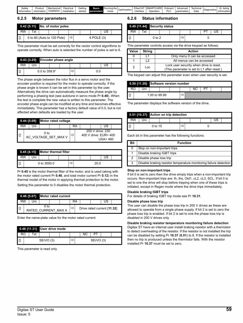
Safety Information
Product information
Mechanical installation
Electrical installation
Getting started
Basic parameters
Running the motor Optimization EtherCAT
interfaceSMARTCARD
OperationOnboard
PLCAdvanced
parametersTechnical
Data Diagnostics UL listing information
6.2.5 Motor parameters
This parameter must be set correctly for the vector control algorithms to operate correctly. When auto is selected the number of poles is set to 6.
The phase angle between the rotor flux in a servo motor and the encoder position is required for the motor to operate correctly. If the phase angle is known it can be set in this parameter by the user. Alternatively the drive can automatically measure the phase angle by performing a phasing test (see autotune in servo mode Pr 0.40). When the test is complete the new value is written to this parameter. The encoder phase angle can be modified at any time and becomes effective immediately. This parameter has a factory default value of 0.0, but is not affected when defaults are loaded by the user.
Pr 0.45 is the motor thermal filter of the motor, and is used (along with the motor rated current Pr 0.46, and total motor current Pr 0.12) in the thermal model of the motor in applying thermal protection to the motor.Setting this parameter to 0 disables the motor thermal protection.
Enter the name-plate value for the motor rated current.
This parameter is read only.
6.2.6 Status information
This parameter controls access via the drive keypad as follows:
The keypad can adjust this parameter even when user security is set.
The parameter displays the software version of the drive.
Each bit in this parameter has the following functions:
Stop on non-important tripsIf bit 0 is set to zero then the drive simply trips when a non-important trip occurs. Non-important trips are: th, ths, Old1, cL2, cL3, SCL. If bit 0 is set to one the drive will stop before tripping when one of these trips is initiated, except in Regen mode where the drive trips immediately. Disable braking IGBT tripsFor details of braking IGBT trip mode see Pr 10.31. Disable phase loss tripThe user can disable the phase loss trip in 200 V drives as these are allowed to operate from a single phase supply. If bit 2 is set to zero the phase loss trip is enabled. If bit 2 is set to one the phase loss trip is disabled in 200 V drives only.Disable braking resistor temperature monitoring failure detectionDigitax ST have an internal user install braking resistor with a thermistor to detect overheating of the resistor. If the resistor is not installed the trip can be disabled by setting Pr 10.37 (0.51) to 8. If the resistor is installed then no trip is produced unless the thermistor fails. With the resistor installed Pr 10.37 must be set to zero.
0.42 {5.11} No. of motor polesRW Txt US
0 to 60 (Auto to 120 Pole) 6 POLE (3)
0.43 {3.25} Encoder phase angleRW Uni US
0.0 to 359.9° 0.0
0.44 {5.09} Motor rated voltageRW Uni RA US
0 to AC_VOLTAGE_SET_MAX V
200 V drive: 230400 V drive: EUR> 400 USA> 460
0.45 {4.15} Motor thermal filter RW Uni US
0 to 3000.0 20.0
0.46 {5.07} Motor rated currentRW Uni RA US
0 to RATED_CURRENT_MAX A Drive rated current [11.32]
0.48 {11.31} User drive modeRO Txt NC PT
SErVO (3) SErVO (3)
0.49 {11.44} Security statusRW Txt PT US
0 to 2 0
Value String Action0 L1 Only menu 0 can be accessed1 L2 All menus can be accessed
2 Loc Lock user security when drive is reset. (This parameter is set to L1 after reset.)
0.50 {11.29} Software version numberRO Uni NC PT
1.00 to 99.99
0.51 {10.37} Action on trip detectionRW Uni US
0 to 15 0
Bit Function0 Stop on non-important trips1 Disable braking IGBT trips2 Disable phase loss trip3 Disable braking resistor temperature monitoring failure detection
Digitax ST User Guide 59Issue: 5
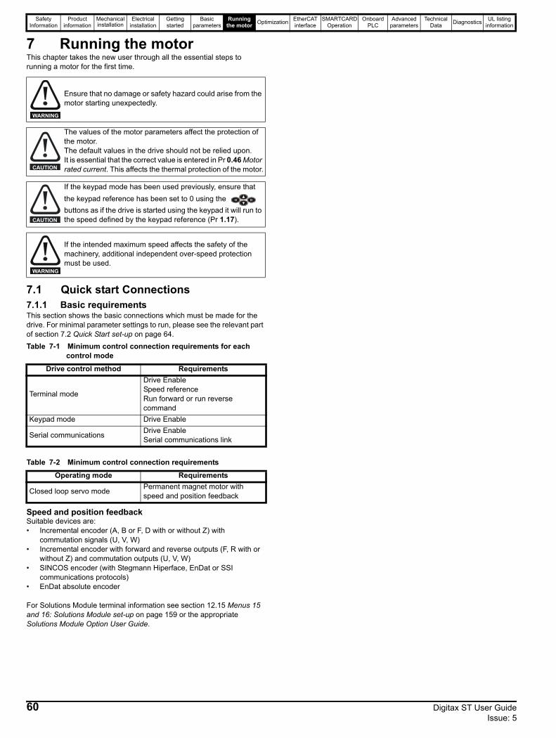
Safety Information
Product information
Mechanical installation
Electrical installation
Getting started
Basic parameters
Running the motor Optimization EtherCAT
interfaceSMARTCARD
OperationOnboard
PLCAdvanced
parametersTechnical
Data Diagnostics UL listing information
7 Running the motorThis chapter takes the new user through all the essential steps to running a motor for the first time.
7.1 Quick start Connections7.1.1 Basic requirements This section shows the basic connections which must be made for the drive. For minimal parameter settings to run, please see the relevant part of section 7.2 Quick Start set-up on page 64. Table 7-1 Minimum control connection requirements for each
control mode
Table 7-2 Minimum control connection requirements
Speed and position feedbackSuitable devices are:• Incremental encoder (A, B or F, D with or without Z) with
commutation signals (U, V, W)• Incremental encoder with forward and reverse outputs (F, R with or
without Z) and commutation outputs (U, V, W)• SINCOS encoder (with Stegmann Hiperface, EnDat or SSI
communications protocols)• EnDat absolute encoder For Solutions Module terminal information see section 12.15 Menus 15 and 16: Solutions Module set-up on page 159 or the appropriate Solutions Module Option User Guide.
Ensure that no damage or safety hazard could arise from the motor starting unexpectedly.
The values of the motor parameters affect the protection of the motor.The default values in the drive should not be relied upon.It is essential that the correct value is entered in Pr 0.46 Motor rated current. This affects the thermal protection of the motor.
If the keypad mode has been used previously, ensure that the keypad reference has been set to 0 using the buttons as if the drive is started using the keypad it will run to the speed defined by the keypad reference (Pr 1.17).
If the intended maximum speed affects the safety of the machinery, additional independent over-speed protection must be used.
Drive control method Requirements
Terminal mode
Drive Enable Speed referenceRun forward or run reverse command
Keypad mode Drive Enable
Serial communications Drive EnableSerial communications link
Operating mode Requirements
Closed loop servo mode Permanent magnet motor with speed and position feedback
WARNING
CAUTION
CAUTION
WARNING
60 Digitax ST User Guide Issue: 5
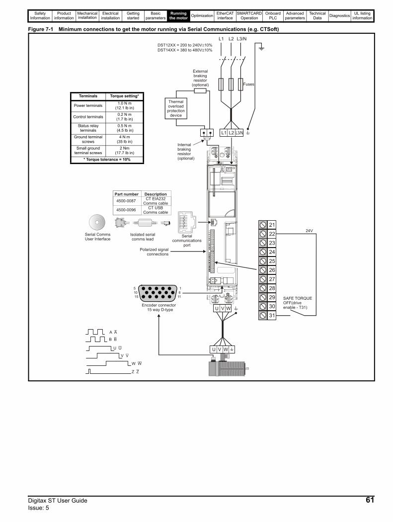
Safety Information
Product information
Mechanical installation
Electrical installation
Getting started
Basic parameters
Running the motor Optimization EtherCAT
interfaceSMARTCARD
OperationOnboard
PLCAdvanced
parametersTechnical
Data Diagnostics UL listing information
Figure 7-1 Minimum connections to get the motor running via Serial Communications (e.g. CTSoft)
U V W 30
31
28
29
26
27
24
25
23
21
22
SAFE TORQUE OFF(driveenable - T31)
24V
U V W
A A
B B
U U
V V
W W
Z Z
Encoder connector15 way D-type
51015
16
11
Serial communications
port
Externalbrakingresistor
(optional)
L3/NL2L1
L2L1
Fuses
Serial CommsUser Interface
Isolated serialcomms lead
DST12XX = 200 to 240V 10%DST14XX = 380 to 480V 10%
±±
Part number DescriptionCT EIA232
Comms cableCT USB
Comms cable
4500-0087
4500-0096
Internalbraking resistor(optional)
Thermaloverloadprotection
device
Polarized signalconnections
Terminals Torque setting*
Power terminals 1.0 N m (12.1 lb in)
Control terminals 0.2 N m (1.7 lb in)
Status relay terminals
0.5 N m (4.5 lb in)
Ground terminalscrews
4 N m (35 lb in)
Small ground terminal screws
2 Nm(17.7 Ib in)
* Torque tolerance = 10%
Digitax ST User Guide 61Issue: 5
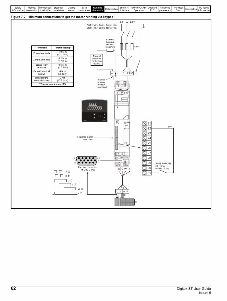
Safety Information
Product information
Mechanical installation
Electrical installation
Getting started
Basic parameters
Running the motor Optimization EtherCAT
interfaceSMARTCARD
OperationOnboard
PLCAdvanced
parametersTechnical
Data Diagnostics UL listing information
Figure 7-2 Minimum connections to get the motor running via keypad
U V W 30
31
28
29
26
27
24
25
23
21
2224V
U V W
A A
B B
U U
V V
W W
Z Z
Encoder connector15 way D-type
51015
16
11
L3/NL2L1
L2L1
Fuses
DST12XX = 200 to 240V 10%DST14XX = 380 to 480V 10%
±±
Internalbraking resistor(optional)
Externalbrakingresistor
(optional)
Thermaloverload
protectiondevice
Polarized signalconnections
SAFE TORQUE OFF(driveenable - T31)
Terminals Torque setting*
Power terminals 1.0 N m (12.1 lb in)
Control terminals 0.2 N m (1.7 lb in)
Status relay terminals
0.5 N m (4.5 lb in)
Ground terminalscrews
4 N m (35 lb in)
Small ground terminal screws
2 Nm(17.7 Ib in)
* Torque tolerance = 10%
62 Digitax ST User Guide Issue: 5
Safety Information
Product information
Mechanical installation
Electrical installation
Getting started
Basic parameters
Running the motor Optimization EtherCAT
interfaceSMARTCARD
OperationOnboard
PLCAdvanced
parametersTechnical
Data Diagnostics UL listing information
Figure 7-3 Minimum connections to get the motor running via terminal mode (analog input)
U V W 30
31
28
29
26
27
24
25
23
21
2224V
U V W
A A
B B
U U
V V
W W
Z Z
Encoder connector15 way D-type
51015
16
11
L3/NL2L1
L2L1
Fuses
DST12XX = 200 to 240V 10%DST14XX = 380 to 480V 10%
±±
Internalbraking resistor(optional)
10
11
8
9
6
7
4
5
3
1
2
Speedreferenceinput
0V+10V
Externalbrakingresistor
(optional)
Thermaloverload
protectiondevice
Runreverse
Runforward
Polarized signalconnections
SAFE TORQUE OFF(driveenable - T31)
Terminals Torque setting*
Power terminals 1.0 N m (12.1 lb in)
Control terminals 0.2 N m (1.7 lb in)
Status relay terminals
0.5 N m (4.5 lb in)
Ground terminalscrews
4 N m (35 lb in)
Small ground terminal screws
2 Nm(17.7 Ib in)
* Torque tolerance = 10%
Digitax ST User Guide 63Issue: 5
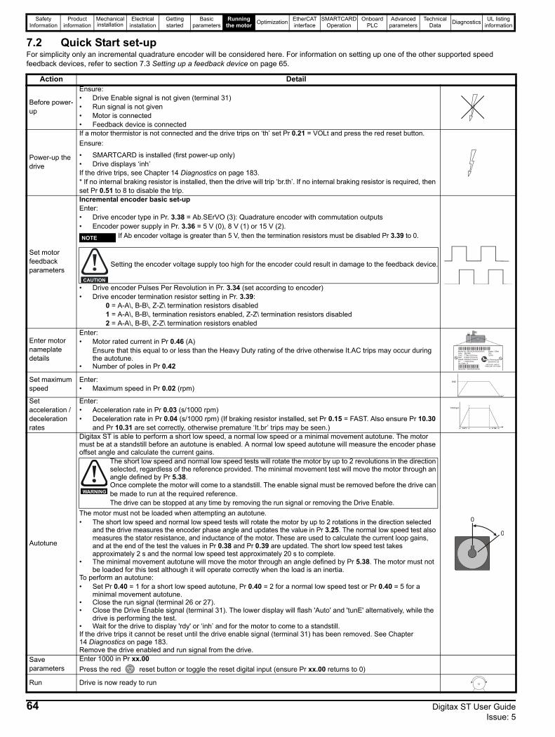
Safety Information
Product information
Mechanical installation
Electrical installation
Getting started
Basic parameters
Running the motor Optimization EtherCAT
interfaceSMARTCARD
OperationOnboard
PLCAdvanced
parametersTechnical
Data Diagnostics UL listing information
7.2 Quick Start set-upFor simplicity only an incremental quadrature encoder will be considered here. For information on setting up one of the other supported speed feedback devices, refer to section 7.3 Setting up a feedback device on page 65.
Action Detail
Before power-up
Ensure:• Drive Enable signal is not given (terminal 31)• Run signal is not given• Motor is connected• Feedback device is connected
Power-up the drive
If a motor thermistor is not connected and the drive trips on ‘th’ set Pr 0.21 = VOLt and press the red reset button.Ensure:
• SMARTCARD is installed (first power-up only)• Drive displays ‘inh’ If the drive trips, see Chapter 14 Diagnostics on page 183.* If no internal braking resistor is installed, then the drive will trip ‘br.th’. If no internal braking resistor is required, then set Pr 0.51 to 8 to disable the trip.
Set motor feedback parameters
Incremental encoder basic set-upEnter:• Drive encoder type in Pr. 3.38 = Ab.SErVO (3): Quadrature encoder with commutation outputs• Encoder power supply in Pr. 3.36 = 5 V (0), 8 V (1) or 15 V (2).
If Ab encoder voltage is greater than 5 V, then the termination resistors must be disabled Pr 3.39 to 0.
• Drive encoder Pulses Per Revolution in Pr. 3.34 (set according to encoder)• Drive encoder termination resistor setting in Pr. 3.39:
0 = A-A\, B-B\, Z-Z\ termination resistors disabled1 = A-A\, B-B\, termination resistors enabled, Z-Z\ termination resistors disabled2 = A-A\, B-B\, Z-Z\ termination resistors enabled
Enter motor nameplate details
Enter:• Motor rated current in Pr 0.46 (A)
Ensure that this equal to or less than the Heavy Duty rating of the drive otherwise It.AC trips may occur during the autotune.
• Number of poles in Pr 0.42
Set maximum speed
Enter:• Maximum speed in Pr 0.02 (rpm)
Set acceleration / deceleration rates
Enter:• Acceleration rate in Pr 0.03 (s/1000 rpm)• Deceleration rate in Pr 0.04 (s/1000 rpm) (If braking resistor installed, set Pr 0.15 = FAST. Also ensure Pr 10.30
and Pr 10.31 are set correctly, otherwise premature ‘It.br’ trips may be seen.)
Autotune
Digitax ST is able to perform a short low speed, a normal low speed or a minimal movement autotune. The motor must be at a standstill before an autotune is enabled. A normal low speed autotune will measure the encoder phase offset angle and calculate the current gains.
The motor must not be loaded when attempting an autotune.• The short low speed and normal low speed tests will rotate the motor by up to 2 rotations in the direction selected
and the drive measures the encoder phase angle and updates the value in Pr 3.25. The normal low speed test also measures the stator resistance, and inductance of the motor. These are used to calculate the current loop gains, and at the end of the test the values in Pr 0.38 and Pr 0.39 are updated. The short low speed test takes approximately 2 s and the normal low speed test approximately 20 s to complete.
• The minimal movement autotune will move the motor through an angle defined by Pr 5.38. The motor must not be loaded for this test although it will operate correctly when the load is an inertia.
To perform an autotune:• Set Pr 0.40 = 1 for a short low speed autotune, Pr 0.40 = 2 for a normal low speed test or Pr 0.40 = 5 for a
minimal movement autotune.• Close the run signal (terminal 26 or 27).• Close the Drive Enable signal (terminal 31). The lower display will flash 'Auto' and 'tunE' alternatively, while the
drive is performing the test.• Wait for the drive to display 'rdy' or ‘inh’ and for the motor to come to a standstill.If the drive trips it cannot be reset until the drive enable signal (terminal 31) has been removed. See Chapter 14 Diagnostics on page 183.Remove the drive enabled and run signal from the drive.
Save parameters
Enter 1000 in Pr xx.00Press the red reset button or toggle the reset digital input (ensure Pr xx.00 returns to 0)
Run Drive is now ready to run
NOTE
Setting the encoder voltage supply too high for the encoder could result in damage to the feedback device.
CAUTION
Model No: 95UXXXXXXXXXXXXVolts: 380/480Cont: 7.7Nm:4.81ArmsStall: 9.5Nm:5.91ArmsSpeed: 3000rpm Poles:6Kt: 1.6Nm/ArmsIns Class: H
Brake: 12Nm24V0.67A
Serial No: XXXXXXXXXXX
Control TechniquesDynamics Ltd
ANDOVER, HANTS.ENGLAND. SP10 5AB
0.02
t
1000rpm
0.03t
0.04
The short low speed and normal low speed tests will rotate the motor by up to 2 revolutions in the direction selected, regardless of the reference provided. The minimal movement test will move the motor through an angle defined by Pr 5.38.Once complete the motor will come to a standstill. The enable signal must be removed before the drive can be made to run at the required reference.The drive can be stopped at any time by removing the run signal or removing the Drive Enable.
WARNING
0
0
64 Digitax ST User Guide Issue: 5
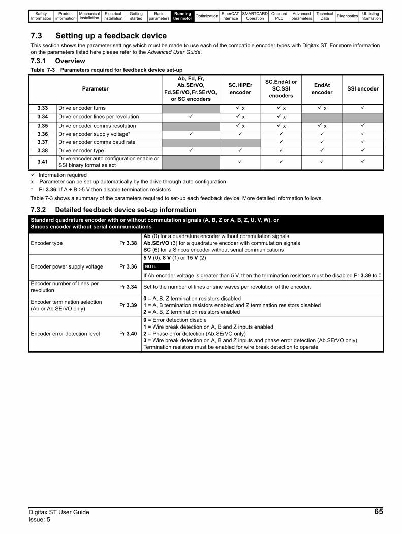
Safety Information
Product information
Mechanical installation
Electrical installation
Getting started
Basic parameters
Running the motor Optimization EtherCAT
interfaceSMARTCARD
OperationOnboard
PLCAdvanced
parametersTechnical
Data Diagnostics UL listing information
7.3 Setting up a feedback deviceThis section shows the parameter settings which must be made to use each of the compatible encoder types with Digitax ST. For more information on the parameters listed here please refer to the Advanced User Guide.
7.3.1 OverviewTable 7-3 Parameters required for feedback device set-up
Parameter
Ab, Fd, Fr, Ab.SErVO,
Fd.SErVO, Fr.SErVO, or SC encoders
SC.HiPEr encoder
SC.EndAt or SC.SSI
encoders
EndAt encoder SSI encoder
3.33 Drive encoder turns x x x3.34 Drive encoder lines per revolution x x3.35 Drive encoder comms resolution x x x3.36 Drive encoder supply voltage*3.37 Drive encoder comms baud rate3.38 Drive encoder type
3.41 Drive encoder auto configuration enable or SSI binary format select
Information requiredx Parameter can be set-up automatically by the drive through auto-configuration* Pr 3.36: If A + B >5 V then disable termination resistorsTable 7-3 shows a summary of the parameters required to set-up each feedback device. More detailed information follows.
7.3.2 Detailed feedback device set-up informationStandard quadrature encoder with or without commutation signals (A, B, Z or A, B, Z, U, V, W), or Sincos encoder without serial communications
Encoder type Pr 3.38Ab (0) for a quadrature encoder without commutation signals Ab.SErVO (3) for a quadrature encoder with commutation signalsSC (6) for a Sincos encoder without serial communications
Encoder power supply voltage Pr 3.365 V (0), 8 V (1) or 15 V (2)
If Ab encoder voltage is greater than 5 V, then the termination resistors must be disabled Pr 3.39 to 0
Encoder number of lines per revolution Pr 3.34 Set to the number of lines or sine waves per revolution of the encoder.
Encoder termination selection (Ab or Ab.SErVO only) Pr 3.39
0 = A, B, Z termination resistors disabled1 = A, B termination resistors enabled and Z termination resistors disabled2 = A, B, Z termination resistors enabled
Encoder error detection level Pr 3.40
0 = Error detection disable1 = Wire break detection on A, B and Z inputs enabled2 = Phase error detection (Ab.SErVO only)3 = Wire break detection on A, B and Z inputs and phase error detection (Ab.SErVO only)Termination resistors must be enabled for wire break detection to operate
NOTE
Digitax ST User Guide 65Issue: 5

Safety Information
Product information
Mechanical installation
Electrical installation
Getting started
Basic parameters
Running the motor Optimization EtherCAT
interfaceSMARTCARD
OperationOnboard
PLCAdvanced
parametersTechnical
Data Diagnostics UL listing information
Incremental encoder with frequency and direction (F and D), or Forward and Reverse (CW and CCW) signals, with or without commutation signals
Encoder type Pr 3.38
Fd (1) for frequency and direction signals without commutation signals Fr (2) for forward and reverse signals without commutation signals Fd.SErVO (4) for a frequency and direction encoder with commutation signalsFr.SErVO (5) for forward and reverse signals with commutation signals
Encoder power supply voltage Pr 3.365 V (0), 8 V (1) or 15 V (2)
If Ab encoder voltage is greater than 5 V, then the termination resistors must be disabled Pr 3.39 to 0
Encoder number of lines per revolution Pr 3.34 Set to the number of pulses per revolution of the encoder divide by 2.
Encoder termination selection Pr 3.390 = F or CW, D or CCW, Z termination resistors disabled1 = F or CW, D or CCW termination resistors enabled and Z termination resistors disabled2 = For CW, D or CCW, Z termination resistors enabled
Encoder error detection level Pr 3.40
0 = Error detection disable1 = Wire break detection on F & D or CW & CCW, and Z inputs enabled2 = Phase error detection (Fd.SErVO and Fr.SErVO only)3 = Wire break detection on F & D or CW & CCW, and Z inputs and Phase error detection (Fd.SErVO and Fr.SErVO only)Termination resistors must be enabled for wire break detection to operate
NOTE
Absolute Sincos encoder with Hiperface or EnDat serial communications, orAbsolute EnDat communications only encoder
The Digitax ST is compatible with the following Hiperface encoders:SCS 60/70, SCM 60/70, SRS 50/60, SRM 50/60, SHS 170, LINCODER, SCS-KIT 101, SKS36, SKM36, SEK-53.
Encoder type Pr 3.38SC.HiPEr (7) for a Sincos encoder with Hiperface serial communicationsEndAt (8) for an EnDat communications only encoderSC.EndAt (9) for a Sincos encoder with EnDat serial communications
Encoder power supply voltage Pr 3.36 5 V (0), 8 V (1) or 15 V (2)
Encoder auto configure enable Pr 3.41
Setting this to 1 automatically sets up the following parameters:Pr 3.33 Encoder turn bitsPr 3.34 Encoder number of lines of revolution (SC.HiPEr and SC.EndAt only) *Pr 3.35 Encoder single turn comms resolutionAlternatively these parameters can be entered manually.
Encoder comms baud rate(EndAt and SC.EndAt only) Pr 3.37 100 = 100 k, 200 = 200 k, 300 = 300 k, 500 = 500 k, 1000 = 1M, 1500 = 1.5 M, or 2000 = 2 M
Encoder error detection level(SC.HiPEr and SC.EndAt only) Pr 3.40
0 = Error detection disabled1 = Wire break detection on Sin and Cos inputs2 = Phase error detection3 = Wire break detection on Sin and Cos inputs and phase error detection
66 Digitax ST User Guide Issue: 5
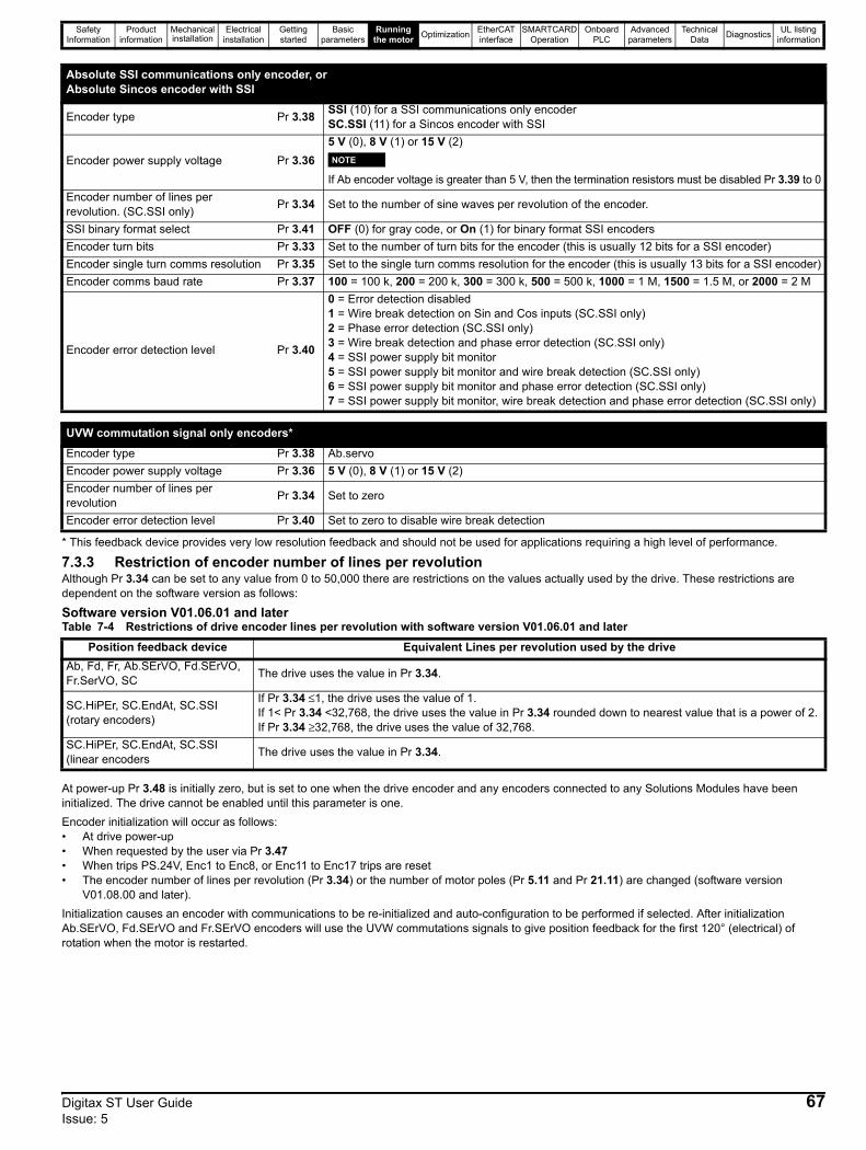
Safety Information
Product information
Mechanical installation
Electrical installation
Getting started
Basic parameters
Running the motor Optimization EtherCAT
interfaceSMARTCARD
OperationOnboard
PLCAdvanced
parametersTechnical
Data Diagnostics UL listing information
* This feedback device provides very low resolution feedback and should not be used for applications requiring a high level of performance.
7.3.3 Restriction of encoder number of lines per revolution Although Pr 3.34 can be set to any value from 0 to 50,000 there are restrictions on the values actually used by the drive. These restrictions are dependent on the software version as follows:
Software version V01.06.01 and laterTable 7-4 Restrictions of drive encoder lines per revolution with software version V01.06.01 and later
At power-up Pr 3.48 is initially zero, but is set to one when the drive encoder and any encoders connected to any Solutions Modules have been initialized. The drive cannot be enabled until this parameter is one.Encoder initialization will occur as follows: • At drive power-up• When requested by the user via Pr 3.47• When trips PS.24V, Enc1 to Enc8, or Enc11 to Enc17 trips are reset• The encoder number of lines per revolution (Pr 3.34) or the number of motor poles (Pr 5.11 and Pr 21.11) are changed (software version
V01.08.00 and later).Initialization causes an encoder with communications to be re-initialized and auto-configuration to be performed if selected. After initialization Ab.SErVO, Fd.SErVO and Fr.SErVO encoders will use the UVW commutations signals to give position feedback for the first 120° (electrical) of rotation when the motor is restarted.
Absolute SSI communications only encoder, orAbsolute Sincos encoder with SSI
Encoder type Pr 3.38 SSI (10) for a SSI communications only encoderSC.SSI (11) for a Sincos encoder with SSI
Encoder power supply voltage Pr 3.365 V (0), 8 V (1) or 15 V (2)
If Ab encoder voltage is greater than 5 V, then the termination resistors must be disabled Pr 3.39 to 0
Encoder number of lines per revolution. (SC.SSI only) Pr 3.34 Set to the number of sine waves per revolution of the encoder.
SSI binary format select Pr 3.41 OFF (0) for gray code, or On (1) for binary format SSI encodersEncoder turn bits Pr 3.33 Set to the number of turn bits for the encoder (this is usually 12 bits for a SSI encoder)Encoder single turn comms resolution Pr 3.35 Set to the single turn comms resolution for the encoder (this is usually 13 bits for a SSI encoder)Encoder comms baud rate Pr 3.37 100 = 100 k, 200 = 200 k, 300 = 300 k, 500 = 500 k, 1000 = 1 M, 1500 = 1.5 M, or 2000 = 2 M
Encoder error detection level Pr 3.40
0 = Error detection disabled1 = Wire break detection on Sin and Cos inputs (SC.SSI only)2 = Phase error detection (SC.SSI only)3 = Wire break detection and phase error detection (SC.SSI only)4 = SSI power supply bit monitor5 = SSI power supply bit monitor and wire break detection (SC.SSI only)6 = SSI power supply bit monitor and phase error detection (SC.SSI only)7 = SSI power supply bit monitor, wire break detection and phase error detection (SC.SSI only)
NOTE
UVW commutation signal only encoders*
Encoder type Pr 3.38 Ab.servoEncoder power supply voltage Pr 3.36 5 V (0), 8 V (1) or 15 V (2)Encoder number of lines per revolution Pr 3.34 Set to zero
Encoder error detection level Pr 3.40 Set to zero to disable wire break detection
Position feedback device Equivalent Lines per revolution used by the driveAb, Fd, Fr, Ab.SErVO, Fd.SErVO, Fr.SerVO, SC The drive uses the value in Pr 3.34.
SC.HiPEr, SC.EndAt, SC.SSI (rotary encoders)
If Pr 3.34 ≤1, the drive uses the value of 1.If 1< Pr 3.34 <32,768, the drive uses the value in Pr 3.34 rounded down to nearest value that is a power of 2.If Pr 3.34 ≥32,768, the drive uses the value of 32,768.
SC.HiPEr, SC.EndAt, SC.SSI (linear encoders The drive uses the value in Pr 3.34.
Digitax ST User Guide 67Issue: 5

Safety Information
Product information
Mechanical installation
Electrical installation
Getting started
Basic parameters
Running the motor Optimization EtherCAT
interfaceSMARTCARD
OperationOnboard
PLCAdvanced
parametersTechnical
Data Diagnostics UL listing information
7.4 Setting up a buffered encoder outputThe Digitax ST has a buffered encoder output, which derives its position from the drive encoder input.The buffered encoder output is sourced from the drive encoder input and can be any incremental type or any SINCOS type.
No output is available if EndAt only or SSI communications only encoders are usedIf a SINCOS is used as the source the buffered output is derived from the zero crossings of the sine waves and does not include interpolated information. The buffered encoder output provides an output with minimal delay from the drive encoder input (maximum delay is 0.5 µs). If the source encoder does not have a marker pulse then no marker pulse can be obtained from the buffered encoder output. This section shows the parameter settings required for the buffered Encoder output.Pr 3.54 selects the type of buffered encoder output as shown in Table 7-5:Table 7-5 Buffered encoder output type
The buffered encoder output can be scaled using Pr 3.52 as shown in the table below:
For more information on the parameters mentioned above please refer to the Advanced User Guide.
Pr 3.54 String Mode
0 Ab Quadrature outputs1 Fd Frequency and direction outputs2 Fr Forward and reverse outputs3 Ab.L Quadrature outputs with marker lock
4 Fd.L Frequency and direction outputs with marker lock
Pr 3.52 Ratio0.0312 1/320.0625 1/160.1250 1/80.2500 1/40.5000 1/21.0000 1
NOTE
68 Digitax ST User Guide Issue: 5
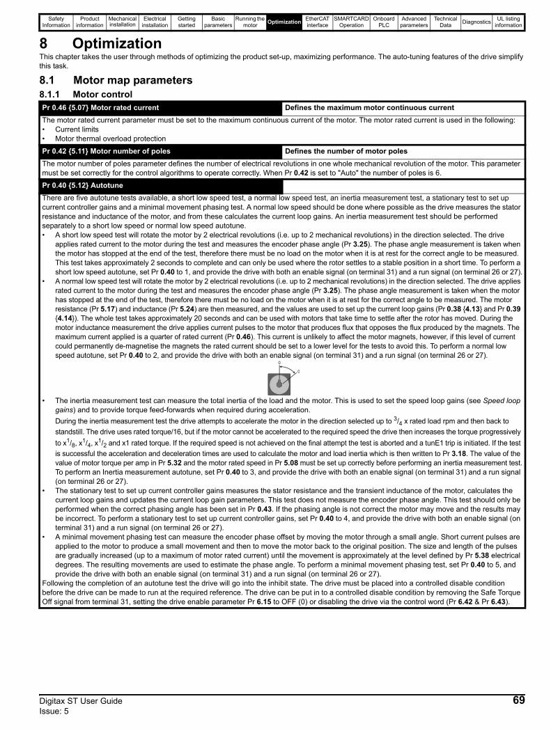
Safety Information
Product information
Mechanical installation
Electrical installation
Getting started
Basic parameters
Running the motor Optimization EtherCAT
interfaceSMARTCARD
OperationOnboard
PLCAdvanced
parametersTechnical
Data Diagnostics UL listing information
8 OptimizationThis chapter takes the user through methods of optimizing the product set-up, maximizing performance. The auto-tuning features of the drive simplify this task.
8.1 Motor map parameters8.1.1 Motor controlPr 0.46 {5.07} Motor rated current Defines the maximum motor continuous current The motor rated current parameter must be set to the maximum continuous current of the motor. The motor rated current is used in the following:• Current limits • Motor thermal overload protection
Pr 0.42 {5.11} Motor number of poles Defines the number of motor polesThe motor number of poles parameter defines the number of electrical revolutions in one whole mechanical revolution of the motor. This parameter must be set correctly for the control algorithms to operate correctly. When Pr 0.42 is set to "Auto" the number of poles is 6.
Pr 0.40 {5.12} Autotune There are five autotune tests available, a short low speed test, a normal low speed test, an inertia measurement test, a stationary test to set up current controller gains and a minimal movement phasing test. A normal low speed should be done where possible as the drive measures the stator resistance and inductance of the motor, and from these calculates the current loop gains. An inertia measurement test should be performed separately to a short low speed or normal low speed autotune.• A short low speed test will rotate the motor by 2 electrical revolutions (i.e. up to 2 mechanical revolutions) in the direction selected. The drive
applies rated current to the motor during the test and measures the encoder phase angle (Pr 3.25). The phase angle measurement is taken when the motor has stopped at the end of the test, therefore there must be no load on the motor when it is at rest for the correct angle to be measured. This test takes approximately 2 seconds to complete and can only be used where the rotor settles to a stable position in a short time. To perform a short low speed autotune, set Pr 0.40 to 1, and provide the drive with both an enable signal (on terminal 31) and a run signal (on terminal 26 or 27).
• A normal low speed test will rotate the motor by 2 electrical revolutions (i.e. up to 2 mechanical revolutions) in the direction selected. The drive applies rated current to the motor during the test and measures the encoder phase angle (Pr 3.25). The phase angle measurement is taken when the motor has stopped at the end of the test, therefore there must be no load on the motor when it is at rest for the correct angle to be measured. The motor resistance (Pr 5.17) and inductance (Pr 5.24) are then measured, and the values are used to set up the current loop gains (Pr 0.38 {4.13} and Pr 0.39 {4.14}). The whole test takes approximately 20 seconds and can be used with motors that take time to settle after the rotor has moved. During the motor inductance measurement the drive applies current pulses to the motor that produces flux that opposes the flux produced by the magnets. The maximum current applied is a quarter of rated current (Pr 0.46). This current is unlikely to affect the motor magnets, however, if this level of current could permanently de-magnetise the magnets the rated current should be set to a lower level for the tests to avoid this. To perform a normal low speed autotune, set Pr 0.40 to 2, and provide the drive with both an enable signal (on terminal 31) and a run signal (on terminal 26 or 27).
• The inertia measurement test can measure the total inertia of the load and the motor. This is used to set the speed loop gains (see Speed loop gains) and to provide torque feed-forwards when required during acceleration.During the inertia measurement test the drive attempts to accelerate the motor in the direction selected up to 3/4 x rated load rpm and then back to standstill. The drive uses rated torque/16, but if the motor cannot be accelerated to the required speed the drive then increases the torque progressively to x1/8, x1/4, x1/2 and x1 rated torque. If the required speed is not achieved on the final attempt the test is aborted and a tunE1 trip is initiated. If the test is successful the acceleration and deceleration times are used to calculate the motor and load inertia which is then written to Pr 3.18. The value of the value of motor torque per amp in Pr 5.32 and the motor rated speed in Pr 5.08 must be set up correctly before performing an inertia measurement test.To perform an Inertia measurement autotune, set Pr 0.40 to 3, and provide the drive with both an enable signal (on terminal 31) and a run signal (on terminal 26 or 27).
• The stationary test to set up current controller gains measures the stator resistance and the transient inductance of the motor, calculates the current loop gains and updates the current loop gain parameters. This test does not measure the encoder phase angle. This test should only be performed when the correct phasing angle has been set in Pr 0.43. If the phasing angle is not correct the motor may move and the results may be incorrect. To perform a stationary test to set up current controller gains, set Pr 0.40 to 4, and provide the drive with both an enable signal (on terminal 31) and a run signal (on terminal 26 or 27).
• A minimal movement phasing test can measure the encoder phase offset by moving the motor through a small angle. Short current pulses are applied to the motor to produce a small movement and then to move the motor back to the original position. The size and length of the pulses are gradually increased (up to a maximum of motor rated current) until the movement is approximately at the level defined by Pr 5.38 electrical degrees. The resulting movements are used to estimate the phase angle. To perform a minimal movement phasing test, set Pr 0.40 to 5, and provide the drive with both an enable signal (on terminal 31) and a run signal (on terminal 26 or 27).
Following the completion of an autotune test the drive will go into the inhibit state. The drive must be placed into a controlled disable condition before the drive can be made to run at the required reference. The drive can be put in to a controlled disable condition by removing the Safe Torque Off signal from terminal 31, setting the drive enable parameter Pr 6.15 to OFF (0) or disabling the drive via the control word (Pr 6.42 & Pr 6.43).
0
0
Digitax ST User Guide 69Issue: 5
Safety Information
Product information
Mechanical installation
Electrical installation
Getting started
Basic parameters
Running the motor Optimization EtherCAT
interfaceSMARTCARD
OperationOnboard
PLCAdvanced
parametersTechnical
Data Diagnostics UL listing information
Current loop gains (Pr 0.38 {4.13} / Pr 0.39 {4.14})The current loop gains proportional (Kp) and integral (Ki) gains control the response of the current loop to a change in current (torque) demand. The default values give satisfactory operation with most motors. However, for optimal performance in dynamic applications it may be necessary to change the gains to improve the performance. The proportional gain (Pr 4.13) is the most critical value in controlling the performance. The values for the current loop gains can be calculated by one of the following:• During a stationary or rotating autotune (see Autotune Pr 0.40, earlier in this table) the drive measures the stator resistance (Pr 5.17) and
transient inductance (Pr 5.24) of the motor and calculates the current loop gains.• By setting Pr 0.40 to 6 the drive will calculate the current loop gains from the values of stator resistance (Pr 5.17) and transient inductance
(Pr 5.24) set in the drive.This will give a step response with minimum overshoot after a step change of current reference. The proportional gain can be increased by a factor of 1.5 giving a similar increase in bandwidth; however, this gives a step response with approximately 12.5 % overshoot. The equation for the integral gain gives a conservative value. In some applications where it is necessary for the reference frame used by the drive to dynamically follow the flux very closely (i.e. high speed closed-loop induction motor applications) the integral gain may need to have a significantly higher value.
70 Digitax ST User Guide Issue: 5
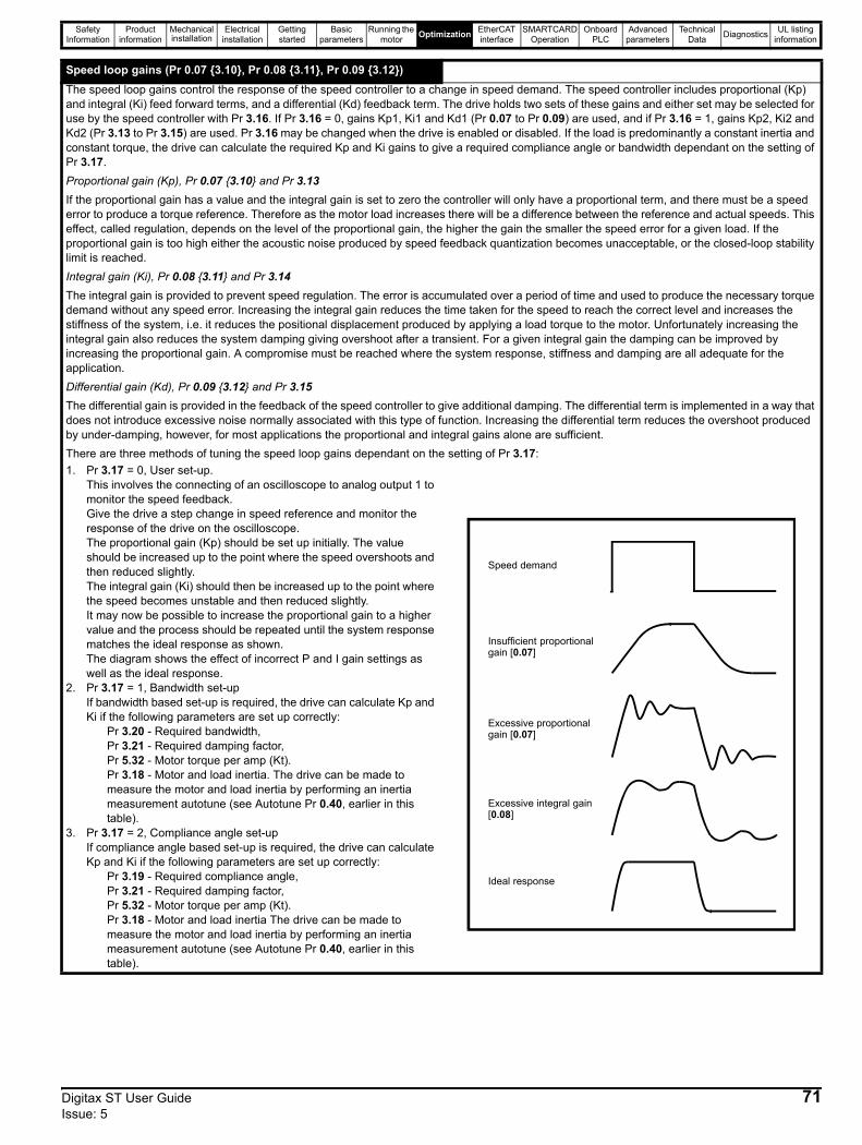
Safety Information
Product information
Mechanical installation
Electrical installation
Getting started
Basic parameters
Running the motor Optimization EtherCAT
interfaceSMARTCARD
OperationOnboard
PLCAdvanced
parametersTechnical
Data Diagnostics UL listing information
Speed loop gains (Pr 0.07 {3.10}, Pr 0.08 {3.11}, Pr 0.09 {3.12})The speed loop gains control the response of the speed controller to a change in speed demand. The speed controller includes proportional (Kp) and integral (Ki) feed forward terms, and a differential (Kd) feedback term. The drive holds two sets of these gains and either set may be selected for use by the speed controller with Pr 3.16. If Pr 3.16 = 0, gains Kp1, Ki1 and Kd1 (Pr 0.07 to Pr 0.09) are used, and if Pr 3.16 = 1, gains Kp2, Ki2 and Kd2 (Pr 3.13 to Pr 3.15) are used. Pr 3.16 may be changed when the drive is enabled or disabled. If the load is predominantly a constant inertia and constant torque, the drive can calculate the required Kp and Ki gains to give a required compliance angle or bandwidth dependant on the setting of Pr 3.17.Proportional gain (Kp), Pr 0.07 {3.10} and Pr 3.13If the proportional gain has a value and the integral gain is set to zero the controller will only have a proportional term, and there must be a speed error to produce a torque reference. Therefore as the motor load increases there will be a difference between the reference and actual speeds. This effect, called regulation, depends on the level of the proportional gain, the higher the gain the smaller the speed error for a given load. If the proportional gain is too high either the acoustic noise produced by speed feedback quantization becomes unacceptable, or the closed-loop stability limit is reached.Integral gain (Ki), Pr 0.08 {3.11} and Pr 3.14The integral gain is provided to prevent speed regulation. The error is accumulated over a period of time and used to produce the necessary torque demand without any speed error. Increasing the integral gain reduces the time taken for the speed to reach the correct level and increases the stiffness of the system, i.e. it reduces the positional displacement produced by applying a load torque to the motor. Unfortunately increasing the integral gain also reduces the system damping giving overshoot after a transient. For a given integral gain the damping can be improved by increasing the proportional gain. A compromise must be reached where the system response, stiffness and damping are all adequate for the application.Differential gain (Kd), Pr 0.09 {3.12} and Pr 3.15The differential gain is provided in the feedback of the speed controller to give additional damping. The differential term is implemented in a way that does not introduce excessive noise normally associated with this type of function. Increasing the differential term reduces the overshoot produced by under-damping, however, for most applications the proportional and integral gains alone are sufficient.There are three methods of tuning the speed loop gains dependant on the setting of Pr 3.17:1. Pr 3.17 = 0, User set-up.
This involves the connecting of an oscilloscope to analog output 1 to monitor the speed feedback.Give the drive a step change in speed reference and monitor the response of the drive on the oscilloscope.The proportional gain (Kp) should be set up initially. The value should be increased up to the point where the speed overshoots and then reduced slightly.The integral gain (Ki) should then be increased up to the point where the speed becomes unstable and then reduced slightly.It may now be possible to increase the proportional gain to a higher value and the process should be repeated until the system response matches the ideal response as shown.The diagram shows the effect of incorrect P and I gain settings as well as the ideal response.
2. Pr 3.17 = 1, Bandwidth set-upIf bandwidth based set-up is required, the drive can calculate Kp and Ki if the following parameters are set up correctly:
Pr 3.20 - Required bandwidth, Pr 3.21 - Required damping factor, Pr 5.32 - Motor torque per amp (Kt).Pr 3.18 - Motor and load inertia. The drive can be made to measure the motor and load inertia by performing an inertia measurement autotune (see Autotune Pr 0.40, earlier in this table).
3. Pr 3.17 = 2, Compliance angle set-upIf compliance angle based set-up is required, the drive can calculate Kp and Ki if the following parameters are set up correctly:
Pr 3.19 - Required compliance angle, Pr 3.21 - Required damping factor, Pr 5.32 - Motor torque per amp (Kt).Pr 3.18 - Motor and load inertia The drive can be made to measure the motor and load inertia by performing an inertia measurement autotune (see Autotune Pr 0.40, earlier in this table).
Speed demand
Insufficient proportional gain [0.07]
Excessive proportional gain [0.07]
Excessive integral gain [0.08]
Ideal response
Digitax ST User Guide 71Issue: 5
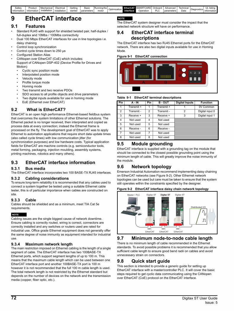
Safety Information
Product information
Mechanical installation
Electrical installation
Getting started
Basic parameters
Running the motor Optimization EtherCAT
interfaceSMARTCARD
OperationOnboard
PLCAdvanced
parametersTechnical
Data Diagnostics UL listing information
9 EtherCAT interface9.1 Features• Standard RJ45 with support for shielded twisted pair, half-duplex /
full-duplex and 10Mbs / 100Mbs connectivity• Dual 100 Mbps EtherCAT interfaces for use in line topologies i.e.
daisy chaining• Control loop synchronization• Control cycle times down to 250 µs• Configured Station Alias• CANopen over EtherCAT (CoE) which includes:
Support of CANopen DSP-402 (Device Profile for Drives and Motion)• Cyclic sync position mode• Interpolated position mode• Velocity mode• Profile torque mode• Homing mode• Two transmit and two receive PDOs• SDO access to all profile objects and drive parameters• Two digital inputs available for use in homing mode• EoE (Ethernet over EtherCAT)
9.2 What is EtherCAT?EtherCAT is an open high performance Ethernet-based fieldbus system that overcomes the system limitations of other Ethernet solutions. The Ethernet packet is no longer received, then interpreted and copied as process data at every connection; instead the Ethernet frame is processed on the fly. The development goal of EtherCAT was to apply Ethernet to automation applications that require short data update times (also called cycle times) with low communication jitter (for synchronization purposes) and low hardware costs. Typical application fields for EtherCAT are machine controls (e.g. semiconductor tools, metal forming, packaging, injection moulding, assembly systems, printing machines, robotics and many others).
9.3 EtherCAT interface information9.3.1 Bus mediaThe EtherCAT interface incorporates two 100 BASE-TX RJ45 interfaces.
9.3.2 Cabling considerationsTo ensure long-term reliability it is recommended that any cables used to connect a system together be tested using a suitable Ethernet cable tester, this is of particular importance when cables are constructed on site.
9.3.3 CableCables should be shielded and as a minimum, meet TIA Cat 5e requirements.
Cabling issues are the single biggest cause of network downtime. Ensure cabling is correctly routed, wiring is correct, connectors are correctly installed and any switches or routers used are rated for industrial use. Office grade Ethernet equipment does not generally offer the same degree of noise immunity as equipment intended for industrial use.
9.3.4 Maximum network lengthThe main restriction imposed on Ethernet cabling is the length of a single segment of cable. The EtherCAT interface has two 100BASE-TX Ethernet ports, which support segment lengths of up to 100 m. This means that the maximum cable length which can be used between one EtherCAT interface port and another 100BASE-TX port is 100 m however it is not recommended that the full 100 m cable length is used. The total network length is not restricted by the Ethernet standard but depends on the number of devices on the network and the transmission media (copper, fiber optic, etc.).
The EtherCAT system designer must consider the impact that the selected network structure will have on performance.
9.4 EtherCAT interface terminal descriptions
The EtherCAT interface has two RJ45 Ethernet ports for the EtherCAT network. There are also two digital inputs available for use in Homing Mode.
Figure 9-1 EtherCAT connection
Table 9-1 EtherCAT terminal descriptions
9.5 Module groundingEtherCAT interface is supplied with a grounding tag on the module that should be connected to the closest possible grounding point using the minimum length of cable. This will greatly improve the noise immunity of the module.
9.6 Network topologyEmerson Industrial Automation recommend implementing daisy chaining on EtherCAT networks (see Figure 9-2). Other Ethernet network topologies can be used but care must be taken to ensure that the system still operates within the constraints specified by the designer.
Figure 9-2 EtherCAT interface daisy chain network topology
9.7 Minimum node-to-node cable lengthThere is no minimum length of cable recommended in the Ethernet standards. To avoid possible problems it is recommended that you allow sufficient cable length to ensure good bend radii on cables and avoid unnecessary strain on connectors.
9.8 Quick start guideThis section is intended to provide a generic guide for setting up EtherCAT interface with a master/controller PLC. It will cover the basic steps required to get cyclic data communicating using the CANopen over EtherCAT (CoE) protocol on the EtherCAT interface.
NOTE
Pin A - IN Pin B - OUT Digital Inputs Function1 Transmit + 1 Transmit + 1 0V Common2 Transmit - 2 Transmit - 2 Digital input 03 Receive + 3 Receive + 3 Digital input 14 Not used 4 Not used5 Not used 5 Not used6 Receive - 6 Receive -7 Not used 7 Not used8 Not used 8 Not used
NOTE
1 2 3
A B
AB
Master / PLC Digitax ST
SM -
EtherCAT
SM -
EtherCAT
Distributed I/O
Digitax STDigitax STDigitax ST
SM -
EtherCAT
72 Digitax ST User Guide Issue: 5
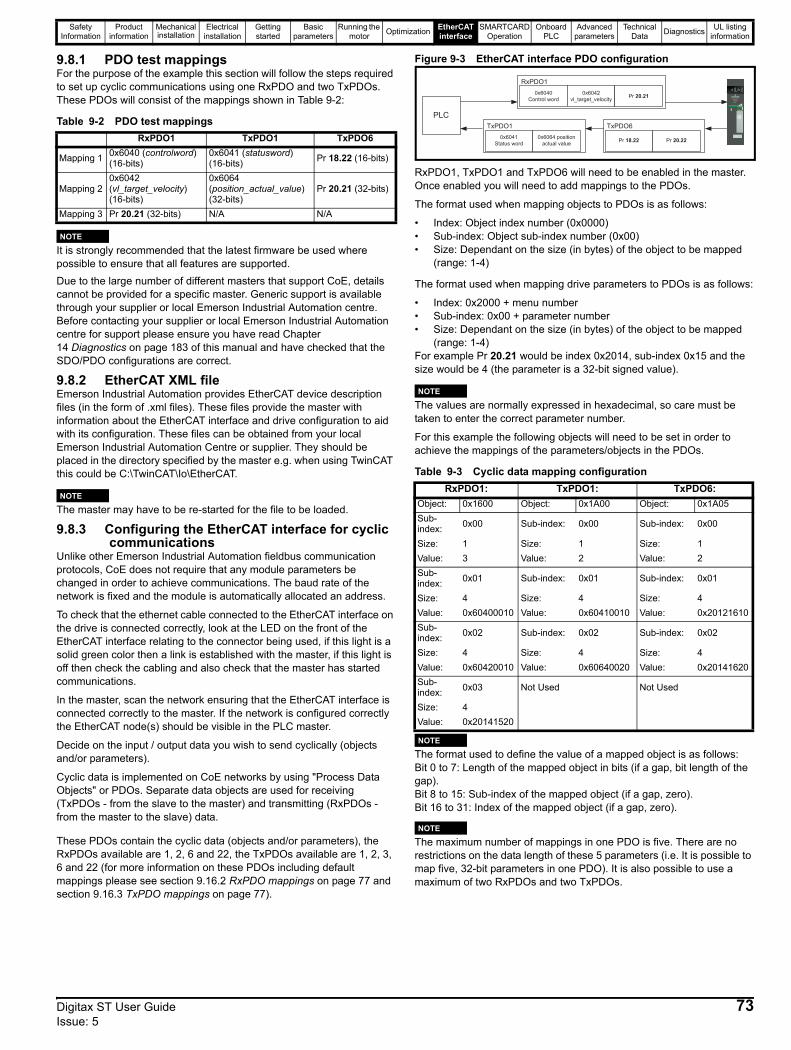
Safety Information
Product information
Mechanical installation
Electrical installation
Getting started
Basic parameters
Running the motor Optimization EtherCAT
interfaceSMARTCARD
OperationOnboard
PLCAdvanced
parametersTechnical
Data Diagnostics UL listing information
9.8.1 PDO test mappingsFor the purpose of the example this section will follow the steps required to set up cyclic communications using one RxPDO and two TxPDOs. These PDOs will consist of the mappings shown in Table 9-2:
Table 9-2 PDO test mappings
It is strongly recommended that the latest firmware be used where possible to ensure that all features are supported.Due to the large number of different masters that support CoE, details cannot be provided for a specific master. Generic support is available through your supplier or local Emerson Industrial Automation centre. Before contacting your supplier or local Emerson Industrial Automation centre for support please ensure you have read Chapter 14 Diagnostics on page 183 of this manual and have checked that the SDO/PDO configurations are correct.
9.8.2 EtherCAT XML fileEmerson Industrial Automation provides EtherCAT device description files (in the form of .xml files). These files provide the master with information about the EtherCAT interface and drive configuration to aid with its configuration. These files can be obtained from your local Emerson Industrial Automation Centre or supplier. They should be placed in the directory specified by the master e.g. when using TwinCAT this could be C:\TwinCAT\Io\EtherCAT.
The master may have to be re-started for the file to be loaded.
9.8.3 Configuring the EtherCAT interface for cyclic communications
Unlike other Emerson Industrial Automation fieldbus communication protocols, CoE does not require that any module parameters be changed in order to achieve communications. The baud rate of the network is fixed and the module is automatically allocated an address.
To check that the ethernet cable connected to the EtherCAT interface on the drive is connected correctly, look at the LED on the front of the EtherCAT interface relating to the connector being used, if this light is a solid green color then a link is established with the master, if this light is off then check the cabling and also check that the master has started communications.
In the master, scan the network ensuring that the EtherCAT interface is connected correctly to the master. If the network is configured correctly the EtherCAT node(s) should be visible in the PLC master.
Decide on the input / output data you wish to send cyclically (objects and/or parameters).
Cyclic data is implemented on CoE networks by using "Process Data Objects" or PDOs. Separate data objects are used for receiving (TxPDOs - from the slave to the master) and transmitting (RxPDOs - from the master to the slave) data.
These PDOs contain the cyclic data (objects and/or parameters), the RxPDOs available are 1, 2, 6 and 22, the TxPDOs available are 1, 2, 3, 6 and 22 (for more information on these PDOs including default mappings please see section 9.16.2 RxPDO mappings on page 77 and section 9.16.3 TxPDO mappings on page 77).
Figure 9-3 EtherCAT interface PDO configuration
RxPDO1, TxPDO1 and TxPDO6 will need to be enabled in the master. Once enabled you will need to add mappings to the PDOs.
The format used when mapping objects to PDOs is as follows:
• Index: Object index number (0x0000)• Sub-index: Object sub-index number (0x00)• Size: Dependant on the size (in bytes) of the object to be mapped
(range: 1-4)
The format used when mapping drive parameters to PDOs is as follows:
• Index: 0x2000 + menu number• Sub-index: 0x00 + parameter number• Size: Dependant on the size (in bytes) of the object to be mapped
(range: 1-4)For example Pr 20.21 would be index 0x2014, sub-index 0x15 and the size would be 4 (the parameter is a 32-bit signed value).
The values are normally expressed in hexadecimal, so care must be taken to enter the correct parameter number.
For this example the following objects will need to be set in order to achieve the mappings of the parameters/objects in the PDOs.
Table 9-3 Cyclic data mapping configuration
The format used to define the value of a mapped object is as follows:Bit 0 to 7: Length of the mapped object in bits (if a gap, bit length of the gap).Bit 8 to 15: Sub-index of the mapped object (if a gap, zero).Bit 16 to 31: Index of the mapped object (if a gap, zero).
The maximum number of mappings in one PDO is five. There are no restrictions on the data length of these 5 parameters (i.e. It is possible to map five, 32-bit parameters in one PDO). It is also possible to use a maximum of two RxPDOs and two TxPDOs.
RxPDO1 TxPDO1 TxPDO6
Mapping 1 0x6040 (controlword)(16-bits)
0x6041 (statusword)(16-bits) Pr 18.22 (16-bits)
Mapping 20x6042 (vl_target_velocity) (16-bits)
0x6064 (position_actual_value)(32-bits)
Pr 20.21 (32-bits)
Mapping 3 Pr 20.21 (32-bits) N/A N/A
NOTE
NOTERxPDO1: TxPDO1: TxPDO6:
Object: 0x1600 Object: 0x1A00 Object: 0x1A05Sub-index: 0x00 Sub-index: 0x00 Sub-index: 0x00
Size: 1 Size: 1 Size: 1Value: 3 Value: 2 Value: 2Sub-index: 0x01 Sub-index: 0x01 Sub-index: 0x01
Size: 4 Size: 4 Size: 4Value: 0x60400010 Value: 0x60410010 Value: 0x20121610Sub-index: 0x02 Sub-index: 0x02 Sub-index: 0x02
Size: 4 Size: 4 Size: 4Value: 0x60420010 Value: 0x60640020 Value: 0x20141620Sub-index: 0x03 Not Used Not Used
Size: 4Value: 0x20141520
0x6041
Status word
0x6064 position
actual value
TxPDO1
Pr 18.22 Pr 20.22
TxPDO6
PLC
0x6040
Control word
0x6042
vl_target_velocityPr 20.21
RxPDO1
NOTE
NOTE
NOTE
Digitax ST User Guide 73Issue: 5
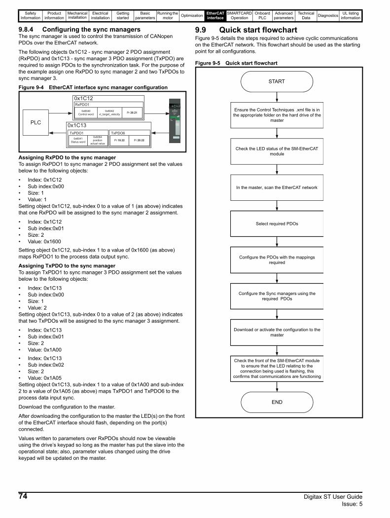
Safety Information
Product information
Mechanical installation
Electrical installation
Getting started
Basic parameters
Running the motor Optimization EtherCAT
interfaceSMARTCARD
OperationOnboard
PLCAdvanced
parametersTechnical
Data Diagnostics UL listing information
9.8.4 Configuring the sync managersThe sync manager is used to control the transmission of CANopen PDOs over the EtherCAT network.
The following objects 0x1C12 - sync manager 2 PDO assignment (RxPDO) and 0x1C13 - sync manager 3 PDO assignment (TxPDO) are required to assign PDOs to the synchronization task. For the purpose of the example assign one RxPDO to sync manager 2 and two TxPDOs to sync manager 3.
Figure 9-4 EtherCAT interface sync manager configuration
Assigning RxPDO to the sync managerTo assign RxPDO1 to sync manager 2 PDO assignment set the values below to the following objects:
• Index: 0x1C12• Sub index:0x00• Size: 1• Value: 1Setting object 0x1C12, sub-index 0 to a value of 1 (as above) indicates that one RxPDO will be assigned to the sync manager 2 assignment.
• Index: 0x1C12• Sub index:0x01• Size: 2• Value: 0x1600Setting object 0x1C12, sub-index 1 to a value of 0x1600 (as above) maps RxPDO1 to the process data output sync.
Assigning TxPDO to the sync managerTo assign TxPDO1 to sync manager 3 PDO assignment set the values below to the following objects:
• Index: 0x1C13• Sub index:0x00• Size: 1• Value: 2Setting object 0x1C13, sub-index 0 to a value of 2 (as above) indicates that two TxPDOs will be assigned to the sync manager 3 assignment.
• Index: 0x1C13• Sub index:0x01• Size: 2• Value: 0x1A00• Index: 0x1C13• Sub index:0x02• Size: 2• Value: 0x1A05Setting object 0x1C13, sub-index 1 to a value of 0x1A00 and sub-index 2 to a value of 0x1A05 (as above) maps TxPDO1 and TxPDO6 to the process data input sync.
Download the configuration to the master.
After downloading the configuration to the master the LED(s) on the front of the EtherCAT interface should flash, depending on the port(s) connected.
Values written to parameters over RxPDOs should now be viewable using the drive’s keypad so long as the master has put the slave into the operational state; also, parameter values changed using the drive keypad will be updated on the master.
9.9 Quick start flowchartFigure 9-5 details the steps required to achieve cyclic communications on the EtherCAT network. This flowchart should be used as the starting point for all configurations.
Figure 9-5 Quick start flowchart
0x1C12
0x6040
Control word
0x6042
vl_target_velocityPr 20.21
RxPDO1
0x1C13
0x6041
Status word
0x6064
position
actual value
TxPDO1
Pr 18.22 Pr 20.22
TxPDO6
PLC
Ensure the Control Techniques .xml file is in the appropriate folder on the hard drive of the
master
Check the LED status of the SM-EtherCAT module
In the master, scan the EtherCAT network
Select required PDOs
Configure the PDOs with the mappings required
Check the front of the SM-EtherCAT module to ensure that the LED relating to the connection being used is flashing, this
confirms that communications are functioning
Download or activate the configuration to the master
Configure the Sync managers using the required PDOs
END
START
74 Digitax ST User Guide Issue: 5
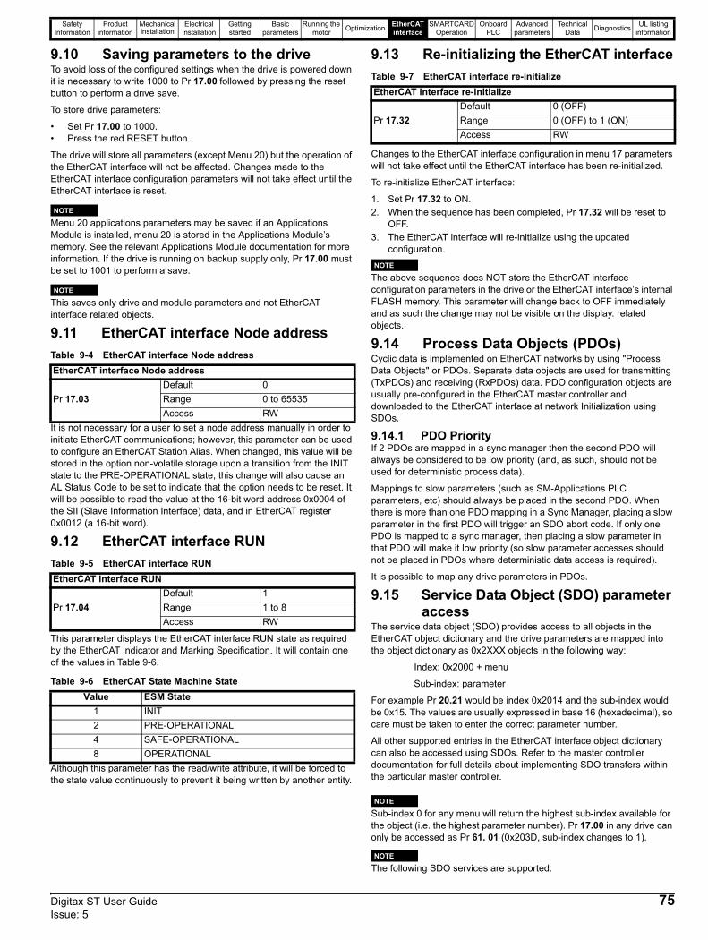
Safety Information
Product information
Mechanical installation
Electrical installation
Getting started
Basic parameters
Running the motor Optimization EtherCAT
interfaceSMARTCARD
OperationOnboard
PLCAdvanced
parametersTechnical
Data Diagnostics UL listing information
9.10 Saving parameters to the driveTo avoid loss of the configured settings when the drive is powered down it is necessary to write 1000 to Pr 17.00 followed by pressing the reset button to perform a drive save.
To store drive parameters:
• Set Pr 17.00 to 1000.• Press the red RESET button.
The drive will store all parameters (except Menu 20) but the operation of the EtherCAT interface will not be affected. Changes made to the EtherCAT interface configuration parameters will not take effect until the EtherCAT interface is reset.
Menu 20 applications parameters may be saved if an Applications Module is installed, menu 20 is stored in the Applications Module’s memory. See the relevant Applications Module documentation for more information. If the drive is running on backup supply only, Pr 17.00 must be set to 1001 to perform a save.
This saves only drive and module parameters and not EtherCAT interface related objects.
9.11 EtherCAT interface Node addressTable 9-4 EtherCAT interface Node address
It is not necessary for a user to set a node address manually in order to initiate EtherCAT communications; however, this parameter can be used to configure an EtherCAT Station Alias. When changed, this value will be stored in the option non-volatile storage upon a transition from the INIT state to the PRE-OPERATIONAL state; this change will also cause an AL Status Code to be set to indicate that the option needs to be reset. It will be possible to read the value at the 16-bit word address 0x0004 of the SII (Slave Information Interface) data, and in EtherCAT register 0x0012 (a 16-bit word).
9.12 EtherCAT interface RUNTable 9-5 EtherCAT interface RUN
This parameter displays the EtherCAT interface RUN state as required by the EtherCAT indicator and Marking Specification. It will contain one of the values in Table 9-6.
Table 9-6 EtherCAT State Machine State
Although this parameter has the read/write attribute, it will be forced to the state value continuously to prevent it being written by another entity.
9.13 Re-initializing the EtherCAT interfaceTable 9-7 EtherCAT interface re-initialize
Changes to the EtherCAT interface configuration in menu 17 parameters will not take effect until the EtherCAT interface has been re-initialized.
To re-initialize EtherCAT interface:
1. Set Pr 17.32 to ON.2. When the sequence has been completed, Pr 17.32 will be reset to
OFF.3. The EtherCAT interface will re-initialize using the updated
configuration.
The above sequence does NOT store the EtherCAT interface configuration parameters in the drive or the EtherCAT interface’s internal FLASH memory. This parameter will change back to OFF immediately and as such the change may not be visible on the display. related objects.
9.14 Process Data Objects (PDOs)Cyclic data is implemented on EtherCAT networks by using "Process Data Objects" or PDOs. Separate data objects are used for transmitting (TxPDOs) and receiving (RxPDOs) data. PDO configuration objects are usually pre-configured in the EtherCAT master controller and downloaded to the EtherCAT interface at network Initialization using SDOs.
9.14.1 PDO PriorityIf 2 PDOs are mapped in a sync manager then the second PDO will always be considered to be low priority (and, as such, should not be used for deterministic process data).
Mappings to slow parameters (such as SM-Applications PLC parameters, etc) should always be placed in the second PDO. When there is more than one PDO mapping in a Sync Manager, placing a slow parameter in the first PDO will trigger an SDO abort code. If only one PDO is mapped to a sync manager, then placing a slow parameter in that PDO will make it low priority (so slow parameter accesses should not be placed in PDOs where deterministic data access is required).
It is possible to map any drive parameters in PDOs.
9.15 Service Data Object (SDO) parameter access
The service data object (SDO) provides access to all objects in the EtherCAT object dictionary and the drive parameters are mapped into the object dictionary as 0x2XXX objects in the following way:
Index: 0x2000 + menu
Sub-index: parameter
For example Pr 20.21 would be index 0x2014 and the sub-index would be 0x15. The values are usually expressed in base 16 (hexadecimal), so care must be taken to enter the correct parameter number.
All other supported entries in the EtherCAT interface object dictionary can also be accessed using SDOs. Refer to the master controller documentation for full details about implementing SDO transfers within the particular master controller.
Sub-index 0 for any menu will return the highest sub-index available for the object (i.e. the highest parameter number). Pr 17.00 in any drive can only be accessed as Pr 61. 01 (0x203D, sub-index changes to 1).
The following SDO services are supported:
EtherCAT interface Node address
Pr 17.03Default 0Range 0 to 65535Access RW
EtherCAT interface RUN
Pr 17.04Default 1Range 1 to 8Access RW
Value ESM State1 INIT2 PRE-OPERATIONAL4 SAFE-OPERATIONAL8 OPERATIONAL
NOTE
NOTE
EtherCAT interface re-initialize
Pr 17.32Default 0 (OFF)Range 0 (OFF) to 1 (ON)Access RW
NOTE
NOTE
NOTE
Digitax ST User Guide 75Issue: 5
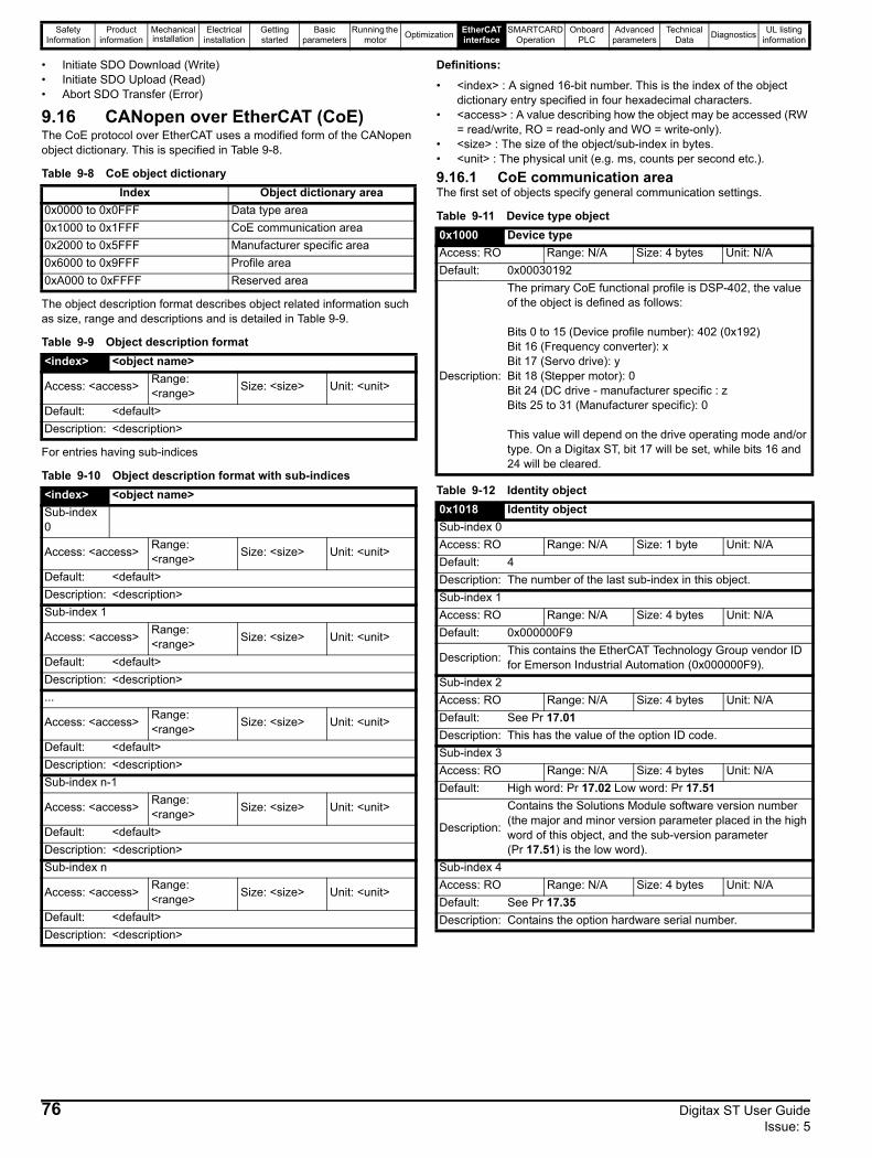
Safety Information
Product information
Mechanical installation
Electrical installation
Getting started
Basic parameters
Running the motor Optimization EtherCAT
interfaceSMARTCARD
OperationOnboard
PLCAdvanced
parametersTechnical
Data Diagnostics UL listing information
• Initiate SDO Download (Write)• Initiate SDO Upload (Read)• Abort SDO Transfer (Error)
9.16 CANopen over EtherCAT (CoE)The CoE protocol over EtherCAT uses a modified form of the CANopen object dictionary. This is specified in Table 9-8.
Table 9-8 CoE object dictionary
The object description format describes object related information such as size, range and descriptions and is detailed in Table 9-9.
Table 9-9 Object description format
For entries having sub-indices
Table 9-10 Object description format with sub-indices
Definitions:
• <index> : A signed 16-bit number. This is the index of the object dictionary entry specified in four hexadecimal characters.
• <access> : A value describing how the object may be accessed (RW = read/write, RO = read-only and WO = write-only).
• <size> : The size of the object/sub-index in bytes.• <unit> : The physical unit (e.g. ms, counts per second etc.).
9.16.1 CoE communication areaThe first set of objects specify general communication settings.
Table 9-11 Device type object
Table 9-12 Identity object
Index Object dictionary area0x0000 to 0x0FFF Data type area0x1000 to 0x1FFF CoE communication area0x2000 to 0x5FFF Manufacturer specific area0x6000 to 0x9FFF Profile area0xA000 to 0xFFFF Reserved area
<index> <object name>
Access: <access> Range: <range> Size: <size> Unit: <unit>
Default: <default>Description: <description>
<index> <object name>Sub-index 0
Access: <access> Range: <range> Size: <size> Unit: <unit>
Default: <default>Description: <description>Sub-index 1
Access: <access> Range: <range> Size: <size> Unit: <unit>
Default: <default>Description: <description>...
Access: <access> Range: <range> Size: <size> Unit: <unit>
Default: <default>Description: <description>Sub-index n-1
Access: <access> Range: <range> Size: <size> Unit: <unit>
Default: <default>Description: <description>Sub-index n
Access: <access> Range: <range> Size: <size> Unit: <unit>
Default: <default>Description: <description>
0x1000 Device typeAccess: RO Range: N/A Size: 4 bytes Unit: N/ADefault: 0x00030192
Description:
The primary CoE functional profile is DSP-402, the value of the object is defined as follows:
Bits 0 to 15 (Device profile number): 402 (0x192)Bit 16 (Frequency converter): xBit 17 (Servo drive): yBit 18 (Stepper motor): 0Bit 24 (DC drive - manufacturer specific : zBits 25 to 31 (Manufacturer specific): 0
This value will depend on the drive operating mode and/or type. On a Digitax ST, bit 17 will be set, while bits 16 and 24 will be cleared.
0x1018 Identity objectSub-index 0Access: RO Range: N/A Size: 1 byte Unit: N/ADefault: 4Description: The number of the last sub-index in this object.Sub-index 1Access: RO Range: N/A Size: 4 bytes Unit: N/ADefault: 0x000000F9
Description: This contains the EtherCAT Technology Group vendor ID for Emerson Industrial Automation (0x000000F9).
Sub-index 2Access: RO Range: N/A Size: 4 bytes Unit: N/ADefault: See Pr 17.01Description: This has the value of the option ID code.Sub-index 3Access: RO Range: N/A Size: 4 bytes Unit: N/ADefault: High word: Pr 17.02 Low word: Pr 17.51
Description:
Contains the Solutions Module software version number (the major and minor version parameter placed in the high word of this object, and the sub-version parameter (Pr 17.51) is the low word).
Sub-index 4Access: RO Range: N/A Size: 4 bytes Unit: N/ADefault: See Pr 17.35Description: Contains the option hardware serial number.
76 Digitax ST User Guide Issue: 5
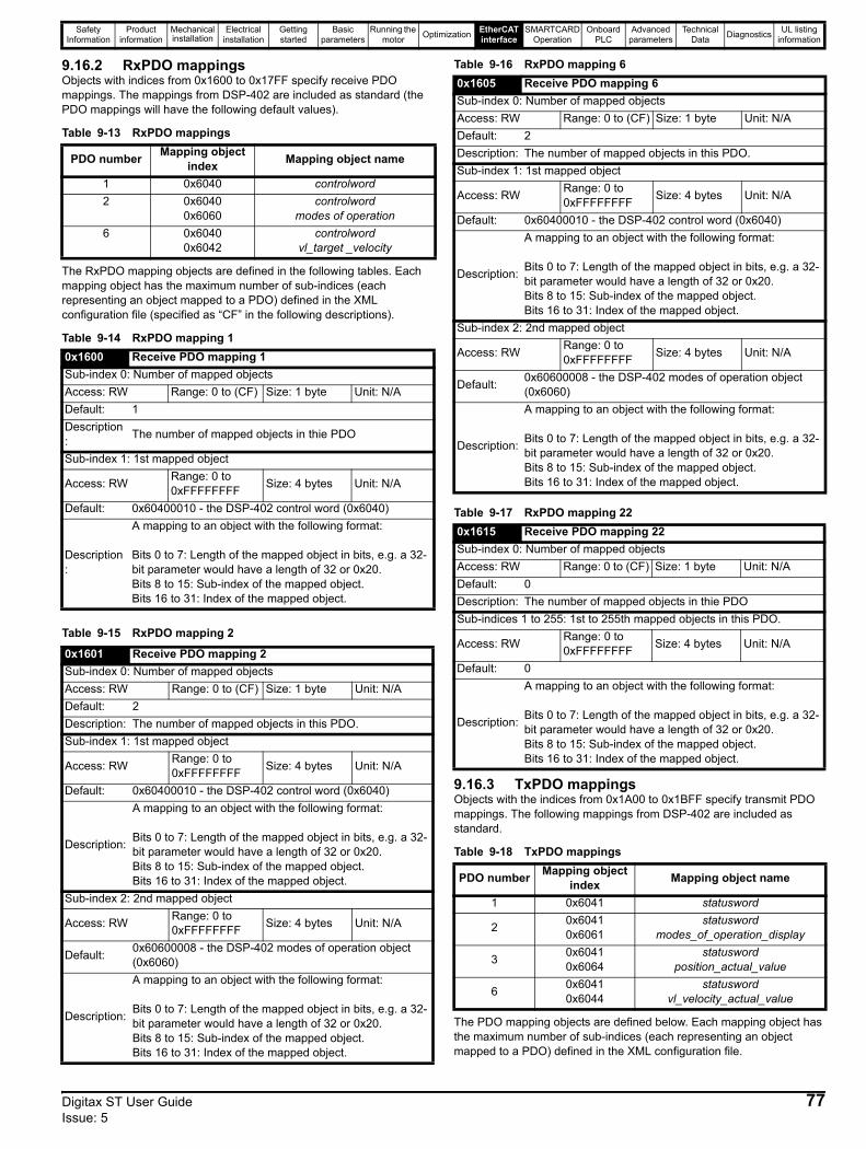
Safety Information
Product information
Mechanical installation
Electrical installation
Getting started
Basic parameters
Running the motor Optimization EtherCAT
interfaceSMARTCARD
OperationOnboard
PLCAdvanced
parametersTechnical
Data Diagnostics UL listing information
9.16.2 RxPDO mappingsObjects with indices from 0x1600 to 0x17FF specify receive PDO mappings. The mappings from DSP-402 are included as standard (the PDO mappings will have the following default values).
Table 9-13 RxPDO mappings
The RxPDO mapping objects are defined in the following tables. Each mapping object has the maximum number of sub-indices (each representing an object mapped to a PDO) defined in the XML configuration file (specified as “CF” in the following descriptions).
Table 9-14 RxPDO mapping 1
Table 9-15 RxPDO mapping 2
Table 9-16 RxPDO mapping 6
Table 9-17 RxPDO mapping 22
9.16.3 TxPDO mappingsObjects with the indices from 0x1A00 to 0x1BFF specify transmit PDO mappings. The following mappings from DSP-402 are included as standard.
Table 9-18 TxPDO mappings
The PDO mapping objects are defined below. Each mapping object has the maximum number of sub-indices (each representing an object mapped to a PDO) defined in the XML configuration file.
PDO number Mapping object index Mapping object name
1 0x6040 controlword2 0x6040
0x6060controlword
modes of operation6 0x6040
0x6042controlword
vl_target _velocity
0x1600 Receive PDO mapping 1Sub-index 0: Number of mapped objectsAccess: RW Range: 0 to (CF) Size: 1 byte Unit: N/ADefault: 1Description: The number of mapped objects in thie PDO
Sub-index 1: 1st mapped object
Access: RW Range: 0 to 0xFFFFFFFF Size: 4 bytes Unit: N/A
Default: 0x60400010 - the DSP-402 control word (0x6040)
Description:
A mapping to an object with the following format:
Bits 0 to 7: Length of the mapped object in bits, e.g. a 32-bit parameter would have a length of 32 or 0x20.Bits 8 to 15: Sub-index of the mapped object.Bits 16 to 31: Index of the mapped object.
0x1601 Receive PDO mapping 2Sub-index 0: Number of mapped objectsAccess: RW Range: 0 to (CF) Size: 1 byte Unit: N/ADefault: 2Description: The number of mapped objects in this PDO.Sub-index 1: 1st mapped object
Access: RW Range: 0 to 0xFFFFFFFF Size: 4 bytes Unit: N/A
Default: 0x60400010 - the DSP-402 control word (0x6040)
Description:
A mapping to an object with the following format:
Bits 0 to 7: Length of the mapped object in bits, e.g. a 32-bit parameter would have a length of 32 or 0x20.Bits 8 to 15: Sub-index of the mapped object.Bits 16 to 31: Index of the mapped object.
Sub-index 2: 2nd mapped object
Access: RW Range: 0 to 0xFFFFFFFF Size: 4 bytes Unit: N/A
Default: 0x60600008 - the DSP-402 modes of operation object (0x6060)
Description:
A mapping to an object with the following format:
Bits 0 to 7: Length of the mapped object in bits, e.g. a 32-bit parameter would have a length of 32 or 0x20.Bits 8 to 15: Sub-index of the mapped object.Bits 16 to 31: Index of the mapped object.
0x1605 Receive PDO mapping 6Sub-index 0: Number of mapped objectsAccess: RW Range: 0 to (CF) Size: 1 byte Unit: N/ADefault: 2Description: The number of mapped objects in this PDO.Sub-index 1: 1st mapped object
Access: RW Range: 0 to 0xFFFFFFFF Size: 4 bytes Unit: N/A
Default: 0x60400010 - the DSP-402 control word (0x6040)
Description:
A mapping to an object with the following format:
Bits 0 to 7: Length of the mapped object in bits, e.g. a 32-bit parameter would have a length of 32 or 0x20.Bits 8 to 15: Sub-index of the mapped object.Bits 16 to 31: Index of the mapped object.
Sub-index 2: 2nd mapped object
Access: RW Range: 0 to 0xFFFFFFFF Size: 4 bytes Unit: N/A
Default: 0x60600008 - the DSP-402 modes of operation object (0x6060)
Description:
A mapping to an object with the following format:
Bits 0 to 7: Length of the mapped object in bits, e.g. a 32-bit parameter would have a length of 32 or 0x20.Bits 8 to 15: Sub-index of the mapped object.Bits 16 to 31: Index of the mapped object.
0x1615 Receive PDO mapping 22Sub-index 0: Number of mapped objectsAccess: RW Range: 0 to (CF) Size: 1 byte Unit: N/ADefault: 0Description: The number of mapped objects in thie PDOSub-indices 1 to 255: 1st to 255th mapped objects in this PDO.
Access: RW Range: 0 to 0xFFFFFFFF Size: 4 bytes Unit: N/A
Default: 0
Description:
A mapping to an object with the following format:
Bits 0 to 7: Length of the mapped object in bits, e.g. a 32-bit parameter would have a length of 32 or 0x20.Bits 8 to 15: Sub-index of the mapped object.Bits 16 to 31: Index of the mapped object.
PDO number Mapping object index Mapping object name
1 0x6041 statusword
2 0x60410x6061
statuswordmodes_of_operation_display
3 0x60410x6064
statuswordposition_actual_value
6 0x60410x6044
statuswordvl_velocity_actual_value
Digitax ST User Guide 77Issue: 5
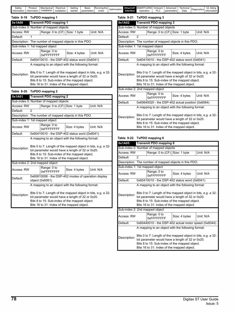
Safety Information
Product information
Mechanical installation
Electrical installation
Getting started
Basic parameters
Running the motor Optimization EtherCAT
interfaceSMARTCARD
OperationOnboard
PLCAdvanced
parametersTechnical
Data Diagnostics UL listing information
Table 9-19 TxPDO mapping 1
Table 9-20 TxPDO mapping 2
Table 9-21 TxPDO mapping 3
Table 9-22 TxPDO mapping 6
0x1A00 Transmit PDO mapping 1Sub-index 0: Number of mapped objectsAccess: RW Range: 0 to (CF) Size: 1 byte Unit: N/ADefault: 1Description: The number of mapped objects in thie PDOSub-index 1: 1st mapped object
Access: RW Range: 0 to 0xFFFFFFFF Size: 4 bytes Unit: N/A
Default: 0x60410010 - the DSP-402 status word (0x6041)
Description:
A mapping to an object with the following format:
Bits 0 to 7: Length of the mapped object in bits, e.g. a 32-bit parameter would have a length of 32 or 0x20.Bits 8 to 15: Sub-index of the mapped object.Bits 16 to 31: Index of the mapped object.
0x1A01 Transmit PDO mapping 2Sub-index 0: Number of mapped objectsAccess: RW Range: 0 to (CF) Size: 1 byte Unit: N/ADefault: 2Description: The number of mapped objects in this PDO.Sub-index 1: 1st mapped object
Access: RW Range: 0 to 0xFFFFFFFF Size: 4 bytes Unit: N/A
Default: 0x60410010 - the DSP-402 status word (0x6041)
Description:
A mapping to an object with the following format:
Bits 0 to 7: Length of the mapped object in bits, e.g. a 32-bit parameter would have a length of 32 or 0x20.Bits 8 to 15: Sub-index of the mapped object.Bits 16 to 31: Index of the mapped object.
Sub-index 2: 2nd mapped object
Access: RW Range: 0 to 0xFFFFFFFF Size: 4 bytes Unit: N/A
Default: 0x60610008 - the DSP-402 modes of operation display object (0x6061)
Description:
A mapping to an object with the following format:
Bits 0 to 7: Length of the mapped object in bits, e.g. a 32-bit parameter would have a length of 32 or 0x20.Bits 8 to 15: Sub-index of the mapped object.Bits 16 to 31: Index of the mapped object.
0x1A02 Transmit PDO mapping 3Sub-index 0: Number of mapped objectsAccess: RW Range: 0 to (CF) Size: 1 byte Unit: N/ADefault: 2Description: The number of mapped objects in this PDO.Sub-index 1: 1st mapped object
Access: RW Range: 0 to 0xFFFFFFFF Size: 4 bytes Unit: N/A
Default: 0x60410010 - the DSP-402 status word (0x6041)
Description:
A mapping to an object with the following format:
Bits 0 to 7: Length of the mapped object in bits, e.g. a 32-bit parameter would have a length of 32 or 0x20.Bits 8 to 15: Sub-index of the mapped object.Bits 16 to 31: Index of the mapped object.
Sub-index 2: 2nd mapped object
Access: RW Range: 0 to 0xFFFFFFFF Size: 4 bytes Unit: N/A
Default: 0x60640020 - the DSP-402 actual position (0x6064)
Description:
A mapping to an object with the following format:
Bits 0 to 7: Length of the mapped object in bits, e.g. a 32-bit parameter would have a length of 32 or 0x20.Bits 8 to 15: Sub-index of the mapped object.Bits 16 to 31: Index of the mapped object.
0x1A05 Transmit PDO mapping 6Sub-index 0: Number of mapped objectsAccess: RW Range: 0 to (CF) Size: 1 byte Unit: N/ADefault: 2Description: The number of mapped objects in this PDO.Sub-index 1: 1st mapped object
Access: RW Range: 0 to 0xFFFFFFFF Size: 4 bytes Unit: N/A
Default: 0x60410010 - the DSP-402 status word (0x6041)
Description:
A mapping to an object with the following format:
Bits 0 to 7: Length of the mapped object in bits, e.g. a 32-bit parameter would have a length of 32 or 0x20.Bits 8 to 15: Sub-index of the mapped object.Bits 16 to 31: Index of the mapped object.
Sub-index 2: 2nd mapped object
Access: RW Range: 0 to 0xFFFFFFFF Size: 4 bytes Unit: N/A
Default: 0x60440010 - the DSP-402 actual motor speed (0x6044).
Description:
A mapping to an object with the following format:
Bits 0 to 7: Length of the mapped object in bits, e.g. a 32-bit parameter would have a length of 32 or 0x20.Bits 8 to 15: Sub-index of the mapped object.Bits 16 to 31: Index of the mapped object.
78 Digitax ST User Guide Issue: 5
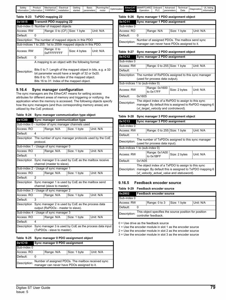
Safety Information
Product information
Mechanical installation
Electrical installation
Getting started
Basic parameters
Running the motor Optimization EtherCAT
interfaceSMARTCARD
OperationOnboard
PLCAdvanced
parametersTechnical
Data Diagnostics UL listing information
Table 9-23 TxPDO mapping 22
9.16.4 Sync manager configurationThe sync managers are the EtherCAT means for setting access attributes for different areas of memory and triggering or notifying the application when the memory is accessed. The following objects specify how the sync managers (and thus corresponding memory areas) are utilized by the CoE protocol.
Table 9-24 Sync manager communication type object
Table 9-25 Sync manager 0 PDO assignment object
Table 9-26 Sync manager 1 PDO assignment object
Table 9-27 Sync manager 2 PDO assignment object
Table 9-28 Sync manager 3 PDO assignment object
9.16.5 Feedback encoder sourceTable 9-29 Feedback encoder source
0 = Use drive as the feedback source1 = Use the encoder module in slot 1 as the encoder source2 = Use the encoder module in slot 2 as the encoder source3 = Use the encoder module in slot 3 as the encoder source
0x1A15 Transmit PDO mapping 22Sub-index 0: Number of mapped objectsAccess: RW Range: 0 to (CF) Size: 1 byte Unit: N/ADefault: 0Description: The number of mapped objects in thie PDOSub-indices 1 to 255: 1st to 255th mapped objects in this PDO.
Access: RW Range: 0 to 0xFFFFFFFF Size: 4 bytes Unit: N/A
Default: 0
Description:
A mapping to an object with the following format:
Bits 0 to 7: Length of the mapped object in bits, e.g. a 32-bit parameter would have a length of 32 or 0x20.Bits 8 to 15: Sub-index of the mapped object.Bits 16 to 31: Index of the mapped object.
0x1C00 Sync manager communication typeSub-index 0 - number of sync manager channels usedAccess: RO Range: N/A Size: 1 byte Unit: N/ADefault: 4Description:
The number of sync manager protocols used by the CoE protocol.
Sub-index 1 - Usage of sync manager 0Access: RO Range: N/A Size: 1 byte Unit: N/ADefault: 1Description:
Sync manager 0 is used by CoE as the mailbox receive channel (master to slave).
Sub-index 2 - Usage of sync manager 1Access: RO Range: N/A Size: 1 byte Unit: N/ADefault: 2Description:
Sync manager 1 is used by CoE as the mailbox send channel (slave to master).
Sub-index 3 - Usage of sync manager 2Access: RO Range: N/A Size: 1 byte Unit: N/ADefault: 3Description:
Sync manager 2 is used by CoE as the process data output (RxPDOx - master to slave).
Sub-index 4 - Usage of sync manager 3Access: RO Range: N/A Size: 1 byte Unit: N/ADefault: 4Description:
Sync manager 3 is used by CoE as the process data input (TxPDOs - slave to master).
0x1C10 Sync manager 0 PDO assignmentSub-index 0Access: RO Range: N/A Size: 1 byte Unit: N/ADefault: 0
Description: Number of assigned PDOs. The mailbox received sync manager can never have PDOs assigned to it.
0x1C11 Sync manager 1 PDO assignmentSub-index 0Access: RO Range: N/A Size: 1 byte Unit: N/ADefault: 0
Description: Number of assigned PDOs. The mailbox send sync manager can never have PDOs assigned to it.
0x1C12 Sync manager 2 PDO assignmentSub-index 0Access: RW Range: 0 to 255 Size: 1 byte Unit: N/ADefault: 1Description:
The number of RxPDOs assigned to this sync manager (used for process data output).
Sub-indices 1 to (sub-index 0)
Access: RW Range: 0x1600 to 0x17FF Size: 2 bytes Unit: N/A
Default: 0x1605
Description:
The object index of a RxPDO to assign to this sync manager. By default this is assigned to RxPDO mapping 6 (vl_target_velocity and controlword).
0x1C13 Sync manager 3 PDO assignmentSub-index 0Access: RW Range: 0 to 255 Size: 1 byte Unit: N/ADefault: 1
Description: The number of TxPDOs assigned to this sync manager (used for process data input).
Sub-indices 1 to (sub-index 0)
Access: RW Range: 0x1A00 to 0x1BFF Size: 2 bytes Unit: N/A
Default: 0x1A05
Description: The object index of a TxPDO to assign to this sync manager. By default this is assigned to TxPDO mapping 6 (vl_velocity_actual_value and statusword).
0x2802 Feedback encoder sourceSub-index 0Access: RW Range: 0 to 3 Size: 1 byte Unit: N/ADefault: 0
Description: This object specifies the source position for position controller feedback.
Digitax ST User Guide 79Issue: 5
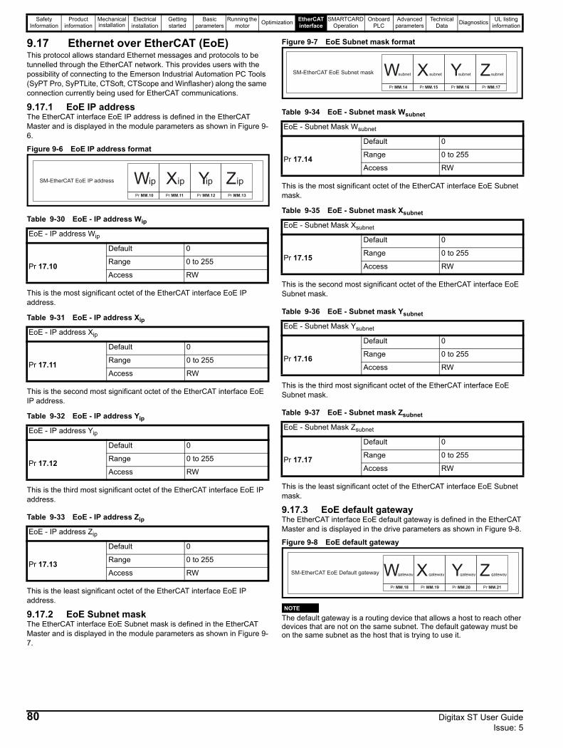
Safety Information
Product information
Mechanical installation
Electrical installation
Getting started
Basic parameters
Running the motor Optimization EtherCAT
interfaceSMARTCARD
OperationOnboard
PLCAdvanced
parametersTechnical
Data Diagnostics UL listing information
9.17 Ethernet over EtherCAT (EoE)This protocol allows standard Ethernet messages and protocols to be tunnelled through the EtherCAT network. This provides users with the possibility of connecting to the Emerson Industrial Automation PC Tools (SyPT Pro, SyPTLite, CTSoft, CTScope and Winflasher) along the same connection currently being used for EtherCAT communications.
9.17.1 EoE IP addressThe EtherCAT interface EoE IP address is defined in the EtherCAT Master and is displayed in the module parameters as shown in Figure 9-6.
Figure 9-6 EoE IP address format
Table 9-30 EoE - IP address Wip
This is the most significant octet of the EtherCAT interface EoE IP address.
Table 9-31 EoE - IP address Xip
This is the second most significant octet of the EtherCAT interface EoE IP address.
Table 9-32 EoE - IP address Yip
This is the third most significant octet of the EtherCAT interface EoE IP address.
Table 9-33 EoE - IP address Zip
This is the least significant octet of the EtherCAT interface EoE IP address.
9.17.2 EoE Subnet maskThe EtherCAT interface EoE Subnet mask is defined in the EtherCAT Master and is displayed in the module parameters as shown in Figure 9-7.
Figure 9-7 EoE Subnet mask format
Table 9-34 EoE - Subnet mask Wsubnet
This is the most significant octet of the EtherCAT interface EoE Subnet mask.
Table 9-35 EoE - Subnet mask Xsubnet
This is the second most significant octet of the EtherCAT interface EoE Subnet mask.
Table 9-36 EoE - Subnet mask Ysubnet
This is the third most significant octet of the EtherCAT interface EoE Subnet mask.
Table 9-37 EoE - Subnet mask Zsubnet
This is the least significant octet of the EtherCAT interface EoE Subnet mask.
9.17.3 EoE default gatewayThe EtherCAT interface EoE default gateway is defined in the EtherCAT Master and is displayed in the drive parameters as shown in Figure 9-8.
Figure 9-8 EoE default gateway
The default gateway is a routing device that allows a host to reach other devices that are not on the same subnet. The default gateway must be on the same subnet as the host that is trying to use it.
EoE - IP address Wip
Pr 17.10
Default 0
Range 0 to 255
Access RW
EoE - IP address Xip
Pr 17.11
Default 0
Range 0 to 255
Access RW
EoE - IP address Yip
Pr 17.12
Default 0
Range 0 to 255
Access RW
EoE - IP address Zip
Pr 17.13
Default 0
Range 0 to 255
Access RW
SM-EtherCAT EoE IP address W Zip Xip Yip ipPr MM.10 Pr MM.11 Pr MM.12 Pr MM.13
EoE - Subnet Mask Wsubnet
Pr 17.14
Default 0
Range 0 to 255
Access RW
EoE - Subnet Mask Xsubnet
Pr 17.15
Default 0
Range 0 to 255
Access RW
EoE - Subnet Mask Ysubnet
Pr 17.16
Default 0
Range 0 to 255
Access RW
EoE - Subnet Mask Zsubnet
Pr 17.17
Default 0
Range 0 to 255
Access RW
SM-EtherCAT EoE Subnet mask W ZX YPr MM.14 Pr MM.15 Pr MM.16 Pr MM.17
subnet subnet subnet subnet
SM-EtherCAT EoE Default gateway W ZX YPr MM.18 Pr MM.19 Pr MM.20 Pr MM.21
gateway gateway gateway gateway
NOTE
80 Digitax ST User Guide Issue: 5

Safety Information
Product information
Mechanical installation
Electrical installation
Getting started
Basic parameters
Running the motor Optimization EtherCAT
interfaceSMARTCARD
OperationOnboard
PLCAdvanced
parametersTechnical
Data Diagnostics UL listing information
Table 9-38 EoE - Default gateway Wgateway
This is the most significant octet of the EtherCAT interface EoE default gateway.
Table 9-39 Default gateway Xgateway
This is the second most significant octet of the EtherCAT interface EoE default gateway.
Table 9-40 Default gateway Ygateway
This is the third most significant octet of the EtherCAT interface EoE default gateway.
Table 9-41 Default gateway Zgateway
This is the least significant octet of the EtherCAT interface EoE default gateway.
Although parameters Pr 17.10 - Pr 17.21 have RW access, changing them via the parameters will have no affect to the EoE settings. The EoE configuration for the EtherCAT interface can only be done with an EtherCAT master which supports the EoE protocol (e.g. TwinCAT). The settings for Pr 17.10 - Pr 17.21 will need to be set by the Master and these parameters are for display purposes only.
9.17.4 EtherCAT interface reduce serial interface priority
Table 9-42 Reduce Drive serial interface priority
It is not possible for the both the Drive and the EtherCAT interface to support all of the available serial communication protocols simultaneously. This means that the user must decide if they wish the drive to provide the primary communication interface via its serial RJ45 connector, or the EtherCAT interface. In the default state the primary interface will be provided by the drive.
Pr 17.37 = OFF (default):
It will not be possible to forward on messages that are intended for either the drive or another Solutions Module. The EtherCAT interface will be able to handle two types of messages:
1. Those that access Drive parameters2. Those that access SM-Applications parameters.
Pr 17.37 = ON:
The EtherCAT interface will request that the drive permits it to become the primary communication interface. If the drive is able to transfer control then the following restrictions will be imposed:
1. The drives serial interface will only be able to handle messages that are 32 bytes or less. A Remote LCD keypad would continue to work, although SM-Application parameters would not be visible. If a message is received that is too long for the drive to handle, no reply will be sent.
2. Any LCD keypad installed (not remotely mounted) to the drive will stop working.
Pr 17.37 must be set to ON to achieve EoE communications.
9.18 Drive profile (DSP-402) supportEtherCAT interface supports the following modes of the DSP-402 profile:• Cyclic sync position mode• Interpolated position mode• vl velocity mode• Profile torque mode• Homing mode
9.18.1 0x6040 ControlwordThis provides the primary method of controlling the behavior of the drive e.g. enabling, disabling, resetting, etc. Table 9-43 describes the format of the control word. The individual bits are used in combinations (see Table 9-44) to sequence the drive through the state machine described in Figure 9-9.
Table 9-43 Controlword
LEGEND: ms = manufacturer-specific; r = reserved; oms = operation mode specific; h = halt; fr = fault reset; hos = homing operation start; eo = enable operation; qs = quick stop; ev = enable voltage; so = switch on
Table 9-44 Command coding
EoE - Default gateway Wgateway
Pr 17.18
Default 0
Range 0 to 255
Access RW
EoE - Default gateway Xgateway
Pr 17.19
Default 0
Range 0 to 255
Access RW
EoE - Default gateway Ygateway
Pr 17.20
Default 0
Range 0 to 255
Access RW
EoE - Default gateway Zgateway
Pr 17.21
Default 0
Range 0 to 255
Access RW
Reduce Drive serial interface priority
Pr 17.37
Default OFF
Range OFF - ON
Access RW
NOTE
0x6040 Controlword
Access: RW Range: 0 to 65535
Size: Unsigned 16 Unit: N/A
Default: N/A
Description: Provides the primary method of controlling the behavior of the drive.
15 14 13 12 11 10 9 8 7 6 5 4 3 2 1 0Reserved ila r oms h fr oms hos eo qs ev so
CommandBits of the controlword
Bit 7 Bit 3 Bit 2 Bit 1 Bit 0Shutdown 0 X 1 1 0Switch on 0 0 1 1 1
Switch on + enableoperation 0 1 1 1 1
Disable voltage 0 X X 0 XQuick stop 0 X 0 1 X
Disable operation 0 0 1 1 1Enable operation 0 1 1 1 1
Fault reset X X X X
NOTE: Automatic transition to Enable operation state after executing SWITCHED ON state functionality.
NOTE
Digitax ST User Guide 81Issue: 5
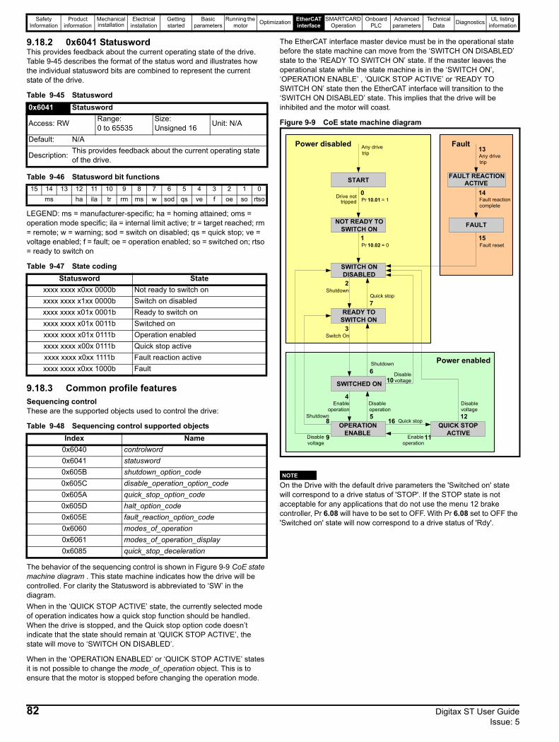
Safety Information
Product information
Mechanical installation
Electrical installation
Getting started
Basic parameters
Running the motor Optimization EtherCAT
interfaceSMARTCARD
OperationOnboard
PLCAdvanced
parametersTechnical
Data Diagnostics UL listing information
9.18.2 0x6041 StatuswordThis provides feedback about the current operating state of the drive. Table 9-45 describes the format of the status word and illustrates how the individual statusword bits are combined to represent the current state of the drive.
Table 9-45 Statusword
Table 9-46 Statusword bit functions
LEGEND: ms = manufacturer-specific; ha = homing attained; oms = operation mode specific; ila = internal limit active; tr = target reached; rm = remote; w = warning; sod = switch on disabled; qs = quick stop; ve = voltage enabled; f = fault; oe = operation enabled; so = switched on; rtso = ready to switch on
Table 9-47 State coding
9.18.3 Common profile featuresSequencing controlThese are the supported objects used to control the drive:
Table 9-48 Sequencing control supported objects
The behavior of the sequencing control is shown in Figure 9-9 CoE state machine diagram . This state machine indicates how the drive will be controlled. For clarity the Statusword is abbreviated to ‘SW’ in the diagram.When in the ‘QUICK STOP ACTIVE’ state, the currently selected mode of operation indicates how a quick stop function should be handled. When the drive is stopped, and the Quick stop option code doesn’t indicate that the state should remain at ‘QUICK STOP ACTIVE’, the state will move to ‘SWITCH ON DISABLED’.
When in the ‘OPERATION ENABLED’ or ‘QUICK STOP ACTIVE’ states it is not possible to change the mode_of_operation object. This is to ensure that the motor is stopped before changing the operation mode.
The EtherCAT interface master device must be in the operational state before the state machine can move from the ‘SWITCH ON DISABLED’ state to the ‘READY TO SWITCH ON’ state. If the master leaves the operational state while the state machine is in the ‘SWITCH ON’, ‘OPERATION ENABLE’ , ‘QUICK STOP ACTIVE’ or ‘READY TO SWITCH ON’ state then the EtherCAT interface will transition to the ‘SWITCH ON DISABLED’ state. This implies that the drive will be inhibited and the motor will coast.
Figure 9-9 CoE state machine diagram
On the Drive with the default drive parameters the 'Switched on' state will correspond to a drive status of 'STOP'. If the STOP state is not acceptable for any applications that do not use the menu 12 brake controller, Pr 6.08 will have to be set to OFF. With Pr 6.08 set to OFF the 'Switched on' state will now correspond to a drive status of 'Rdy'.
0x6041 Statusword
Access: RW Range: 0 to 65535
Size: Unsigned 16 Unit: N/A
Default: N/A
Description: This provides feedback about the current operating state of the drive.
15 14 13 12 11 10 9 8 7 6 5 4 3 2 1 0ms ha ila tr rm ms w sod qs ve f oe so rtso
Statusword Statexxxx xxxx x0xx 0000b Not ready to switch onxxxx xxxx x1xx 0000b Switch on disabledxxxx xxxx x01x 0001b Ready to switch onxxxx xxxx x01x 0011b Switched onxxxx xxxx x01x 0111b Operation enabledxxxx xxxx x00x 0111b Quick stop activexxxx xxxx x0xx 1111b Fault reaction activexxxx xxxx x0xx 1000b Fault
Index Name0x6040 controlword0x6041 statusword0x605B shutdown_option_code0x605C disable_operation_option_code0x605A quick_stop_option_code0x605D halt_option_code0x605E fault_reaction_option_code0x6060 modes_of_operation0x6061 modes_of_operation_display0x6085 quick_stop_deceleration
SWITCH ONDISABLED
NOT READY TOSWITCH ON
START
READY TOSWITCH ON
SWITCHED ON
OPERATIONENABLE
QUICK STOPACTIVE
FAULT
FAULT REACTIONACTIVE
Pr 10.01 = 1
Pr 10.02 = 0
0
Shutdown
1
2
Switch On3
Enableoperation
4Disableoperation5
Shutdown6
Quick stop7
Shutdown8
9Disablevoltage
10Disablevoltage
16 Quick stop
Disablevoltage12
Any drivetrip
13
Fault reactioncomplete
14
Fault reset15
11Enableoperation
Any drivetrip
Power enabled
FaultPower disabled
Drive nottripped
NOTE
82 Digitax ST User Guide Issue: 5
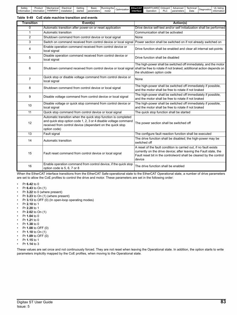
Safety Information
Product information
Mechanical installation
Electrical installation
Getting started
Basic parameters
Running the motor Optimization EtherCAT
interfaceSMARTCARD
OperationOnboard
PLCAdvanced
parametersTechnical
Data Diagnostics UL listing information
Table 9-49 CoE state machine transition and events
When the EtherCAT interface transitions from the EtherCAT Safe-operational state to the EtherCAT Operational state, a number of drive parameters are set to allow the CoE profiles to control the drive and motor. These parameters are set in the following order:
• Pr 6.42 to 0• Pr 6.43 to On (1)• Pr 3.22 to 0 (where present)• Pr 3.23 to On (1) (where present)• Pr 3.13 to OFF (0) (In open-loop operating modes)• Pr 2.10 to 1• Pr 2.20 to 1• Pr 2.02 to On (1)• Pr 1.04 to 0• Pr 1.21 to 0• Pr 1.38 to 0• Pr 1.08 to OFF (0)• Pr 1.10 to On (1)• Pr 1.09 to OFF (0)• Pr 1.15 to 1• Pr 1.14 to 3
These values are set once and not continuously forced. They are not reset when leaving the Operational state. In addition, the option starts to write parameters implicitly mapped by the CoE profiles, when moving to the Operational state.
Transition Event(s) Action(s)0 Automatic transition after power-on or reset application Drive device self-test and/or self Initialization shall be performed1 Automatic transition Communication shall be activated2 Shutdown command from control device or local signal None3 Switch on command received from control device or local signal Power section shall be switched on if not already switched on
4 Enable operation command received from control device or local signal Drive function shall be enabled and clear all internal set-points
5 Disable operation command received from control device or local signal Drive function shall be disabled
6 Shutdown command received from control device or local signalThe high-power shall be switched off immediately, and the motor shall be free to rotate if not braked; additional action depends on the shutdown option code
7 Quick stop or disable voltage command from control device or local signal None
8 Shutdown command from control device or local signal The high-power shall be switched off immediately if possible, and the motor shall be free to rotate if not braked
9 Disable voltage command from control device or local signal The high-power shall be switched off immediately if possible, and the motor shall be free to rotate if not braked
10 Disable voltage or quick stop command from control device or local signal
The high-power shall be switched off immediately if possible, and the motor shall be free to rotate if not braked
11 Quick stop command from control device or local signal The quick stop function shall be started
12
Automatic transition when the quick stop function is completed and quick stop option code 1, 2, 3 or 4 disable voltage command received from control device (dependant on the quick stop option code)
The power section shall be switched off
13 Fault signal The configure fault reaction function shall be executed
14 Automatic transition The drive function shall be disabled; the high-power may be switched off
15 Fault reset command from control device or local signal
A reset of the fault condition is carried out, if no fault exists currently on the drive device; after leaving the Fault state, the Fault reset bit in the controlword shall be cleared by the control device
16 Enable operation command from control device, if the quick stop option code is 5, 6, 7 or 8 The drive function shall be enabled
Digitax ST User Guide 83Issue: 5

Safety Information
Product information
Mechanical installation
Electrical installation
Getting started
Basic parameters
Running the motor Optimization EtherCAT
interfaceSMARTCARD
OperationOnboard
PLCAdvanced
parametersTechnical
Data Diagnostics UL listing information
9.18.4 0x605A Quick stop option codeThis object indicates what action is performed when the quick stop function is executed. The slow down ramp is the deceleration value of the used mode of operations.
Table 9-50 Quick_stop_option_code
Table 9-51 Quick stop value definitions
9.18.5 0x605B Shutdown_option_codeThis object is used to control what action is performed if there is a transition from the Operation Enabled state to the Ready To Switch On state.
Table 9-52 Shutdown_option_code
Table 9-53 Shutdown_option_code values
9.18.6 0x605C Disable_operation_option_codeDisable drive function (switch off the drive power stage).This object is used to control what action is performed if there is a transition from the ‘Operation Enabled’ state to the ‘Switched On’ state.
Table 9-54 Disabled_operation_option_code
Table 9-55 Disable_operation_option_code values
9.18.7 0x605E Fault_reaction_option_codeThis object is used to control what action is performed when a fault is detected. This object is ignored if the drive is tripped.
Table 9-56 Fault_reaction_option_code
Table 9-57 Fault_reaction_option_code values
9.18.8 0x6060 Modes_of_operationThis object is used to request a change in the mode of operation.
Table 9-58 Modes_of_operation
Table 9-59 Modes_of_operation values
9.18.9 0x6061 Modes_of_operation_displayThis read only object indicates the active mode of operation.
Table 9-60 Modes_of_operation_display
Table 9-61 Modes_of_operation_display values
0x605A Quick_stop_option_code
Access: RW Range: 0 to 6 Size: Unsigned 16 Unit: N/A
Default: 2
Description: Specifies what action is performed in the event of a quick stop function. See Table 9-49 CoE state machine transition and events on page 83 for more information.
Value Definition0 Disable drive function
1 Slow down on slow down ramp and transit into Switch on disabled
2 Slow down on quick stop ramp and transit into Switch on disabled
5 Slow down on slow down ramp and stay in Quick stop active
6 Slow down on quick stop ramp and stay in Quick stop active
0x605B Shutdown_option_code
Access: RW Range: 0 to 1 Size: Unsigned 16 Unit: N/A
Default: N/A
Description: Used to control what action is performed if there is a transition from the Operation Enabled state to the Ready To Switch On state.
Value Definition
0 Disable drive function (switch off the drive power stage)
1 Slow down with slow down ramp; disable the drive function
0x605C Disable_operation_option_code
Access: RW Range: 0 to 1 Size: Unsigned 16 Unit: N/A
Default: N/A
Description: This object is used to control what action is performed if there is a transition from the Operation Enabled state to the Switched On state.
Value Definition0 Disable drive function (switch off the drive power
stage)1 Slow down with slow down ramp; disable the drive
function
0x605E Fault_reaction_option_code
Access: RW Range: 0 to 2 Size: Unsigned 16 Unit: N/A
Default: N/A
Description: This object is used to control what action is performed when a fault is detected.
Value Definition0 Disable drive function, motor is free to rotate1 Slow down on slow down ramp2 Slow down on quick stop ramp
0x6060 Modes_of_operation
Access: RW Range: 0 to 8 Size: Unsigned 8 Unit: N/A
Default: 2
Description: This object is used to request a change in the mode of operation.
Value Definition0 No mode change2 vl velocity mode4 Profile torque mode6 Homing mode7 Interpolated position mode8 Cyclic sync position mode
0x6061 Modes_of_operation_display
Access: RO Range: 0 to 8 Size: Unsigned 8 Unit: N/A
Default: N/ADescription: Used to provide the active mode of operation.
Value Definition0 No mode change2 vl velocity mode4 Profile torque mode6 Homing mode7 Interpolated position mode8 Cyclic sync position mode
84 Digitax ST User Guide Issue: 5
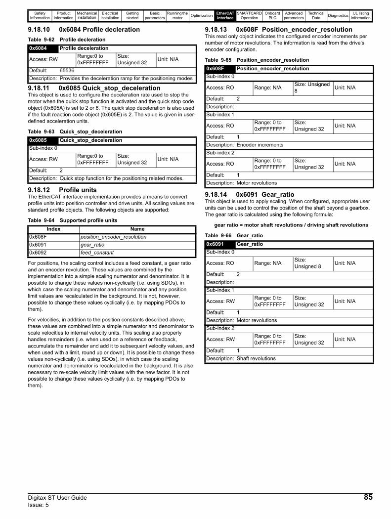
Safety Information
Product information
Mechanical installation
Electrical installation
Getting started
Basic parameters
Running the motor Optimization EtherCAT
interfaceSMARTCARD
OperationOnboard
PLCAdvanced
parametersTechnical
Data Diagnostics UL listing information
9.18.10 0x6084 Profile declerationTable 9-62 Profile decleration
9.18.11 0x6085 Quick_stop_decelerationThis object is used to configure the deceleration rate used to stop the motor when the quick stop function is activated and the quick stop code object (0x605A) is set to 2 or 6. The quick stop deceleration is also used if the fault reaction code object (0x605E) is 2. The value is given in user-defined acceleration units.
Table 9-63 Quick_stop_deceleration
9.18.12 Profile unitsThe EtherCAT interface implementation provides a means to convert profile units into position controller and drive units. All scaling values are standard profile objects. The following objects are supported:
Table 9-64 Supported profile units
For positions, the scaling control includes a feed constant, a gear ratio and an encoder revolution. These values are combined by the implementation into a simple scaling numerator and denominator. It is possible to change these values non-cyclically (i.e. using SDOs), in which case the scaling numerator and denominator and any position limit values are recalculated in the background. It is not, however, possible to change these values cyclically (i.e. by mapping PDOs to them).
For velocities, in addition to the position constants described above, these values are combined into a simple numerator and denominator to scale velocities to internal velocity units. This scaling also properly handles remainders (i.e. when used on a reference or feedback, accumulate the remainder and add it to subsequent velocity values, and when used with a limit, round up or down). It is possible to change these values non-cyclically (i.e. using SDOs), in which case the scaling numerator and denominator is recalculated in the background. It is also necessary to re-scale velocity limit values with the new factor. It is not possible to change these values cyclically (i.e. by mapping PDOs to them).
9.18.13 0x608F Position_encoder_resolutionThis read only object indicates the configured encoder increments per number of motor revolutions. The information is read from the drive's encoder configuration.
Table 9-65 Position_encoder_resolution
9.18.14 0x6091 Gear_ratioThis object is used to apply scaling. When configured, appropriate user units can be used to control the position of the shaft beyond a gearbox. The gear ratio is calculated using the following formula:
gear ratio = motor shaft revolutions / driving shaft revolutions
Table 9-66 Gear_ratio
0x6084 Profile deceleration
Access: RW Range:0 to 0xFFFFFFFF
Size: Unsigned 32 Unit: N/A
Default: 65536Description: Provides the deceleration ramp for the positioning modes
0x6085 Quick_stop_decelerationSub-index 0
Access: RW Range:0 to 0xFFFFFFFF
Size: Unsigned 32 Unit: N/A
Default: 2Description: Quick stop function for the positioning related modes.
Index Name0x608F position_encoder_resolution0x6091 gear_ratio0x6092 feed_constant
0x608F Position_encoder_resolutionSub-index 0
Access: RO Range: N/A Size: Unsigned 8 Unit: N/A
Default: 2Description: Sub-index 1
Access: RO Range: 0 to 0xFFFFFFFF
Size: Unsigned 32 Unit: N/A
Default: 1Description: Encoder incrementsSub-index 2
Access: RO Range: 0 to 0xFFFFFFFF
Size: Unsigned 32 Unit: N/A
Default: 1Description: Motor revolutions
0x6091 Gear_ratioSub-index 0
Access: RO Range: N/A Size: Unsigned 8 Unit: N/A
Default: 2Description: Sub-index 1
Access: RW Range: 0 to 0xFFFFFFFF
Size: Unsigned 32 Unit: N/A
Default: 1Description: Motor revolutionsSub-index 2
Access: RW Range: 0 to 0xFFFFFFFF
Size: Unsigned 32 Unit: N/A
Default: 1Description: Shaft revolutions
Digitax ST User Guide 85Issue: 5
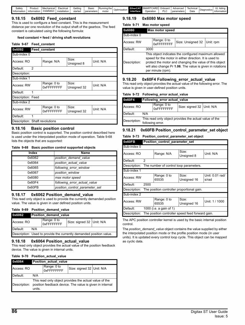
Safety Information
Product information
Mechanical installation
Electrical installation
Getting started
Basic parameters
Running the motor Optimization EtherCAT
interfaceSMARTCARD
OperationOnboard
PLCAdvanced
parametersTechnical
Data Diagnostics UL listing information
9.18.15 0x6092 Feed_constantThis is used to configure a feed constant. This is the measurement distance per one revolution of the output shaft of the gearbox. The feed constant is calculated using the following formula:
feed constant = feed / driving shaft revolutions
Table 9-67 Feed_constant
9.18.16 Basic position controlBasic position control is supported. The position control described here is used under the interpolated position mode of operation. Table 9-68 lists the objects that are supported:
Table 9-68 Basic position control supported objects
9.18.17 0x6062 Position_demand_valueThis read only object is used to provide the currently demanded position value. The value is given in user defined position units.
Table 9-69 Position_demand_value
9.18.18 0x6064 Position_actual_valueThis read only object provides the actual value of the position feedback device. The value is given in internal units.
Table 9-70 Position_actual_value
9.18.19 0x6080 Max motor speedTable 9-71 Max motor speed
9.18.20 0x60F4 Following_error_actual_valueThis read only object provides the actual value of the following error. The value is given in user-defined position units.
Table 9-72 Following_error actual_value
9.18.21 0x60FB Position_control_parameter_set objectTable 9-73 Position_control_parameter_set object
The APC position controller kernel is used by the basic internal position control.The position_demand_value object contains the value supplied by either the interpolated position mode or the profile position mode (in user units). It is updated every control loop cycle. This object can be mapped as cyclic data.
0x6092 Feed_constantSub-index 0
Access: RO Range: N/A Size: Unsigned 8 Unit: N/A
Default: 2Description: Sub-index 1
Access: RW Range: 0 to 0xFFFFFFFF
Size: Unsigned 32 Unit: N/A
Default: 1Description: Feed Sub-index 2
Access: RW Range: 0 to 0xFFFFFFFF
Size: Unsigned 32 Unit: N/A
Default: 1Description: Shaft revolutions
Index Name0x6062 position_demand_value0x6064 position_actual_value0x6065 following_error_window0x6067 position_window0x6080 max motor speed0x60F4 following_error_actual_value0x60FB position_control_parameter_set
0x6062 Position_demand_value
Access: RO Range: 0 to 0xFFFFFFFF Size: signed 32 Unit: N/A
Default: N/ADescription: Used to provide the currently demanded position value.
0x6064 Position_actual_value
Access: RO Range: 0 to 0xFFFFFFFF Size: signed 32 Unit: N/A
Default: N/A
Description: This read only object provides the actual value of the position feedback device. The value is given in internal units.
0x6080 Max motor speedSub-index 0
Access: RW Range: 0 to 0xFFFFFFFF Size: Unsigned 32 Unit: rpm
Default: 3000
Description:
This object indicates the configured maximum allowed speed for the motor in either direction. It is used to protect the motor and changing the value of this object will also change Pr 1.06. The value is given in rotations per minute (rpm).
0x60F4 Following_error actual_value
Access: RO Range: 0 to 0xFFFFFFFF Size: signed 32 Unit: N/A
Default: N/A
Description: This read only object provides the actual value of the following error.
0x60FB Position_control_parameter_setSub-index 0
Access: RO Range: N/A Size: Unsigned 8 Unit: N/A
Default: 2Description: The number of control loop parameters.Sub-index 1
Access: RW Range: 0 to 65535
Size: Unsigned 16
Unit: 0.01 rad/s/rad
Default: 2500Description: The position controller proportional gain.Sub-index 2
Access: RW Range: 0 to 65535
Size: Unsigned 16 Unit: 1 / 1000
Default: 1000 (i.e. a gain of 1)Description: The position controller speed feed forward gain.
86 Digitax ST User Guide Issue: 5
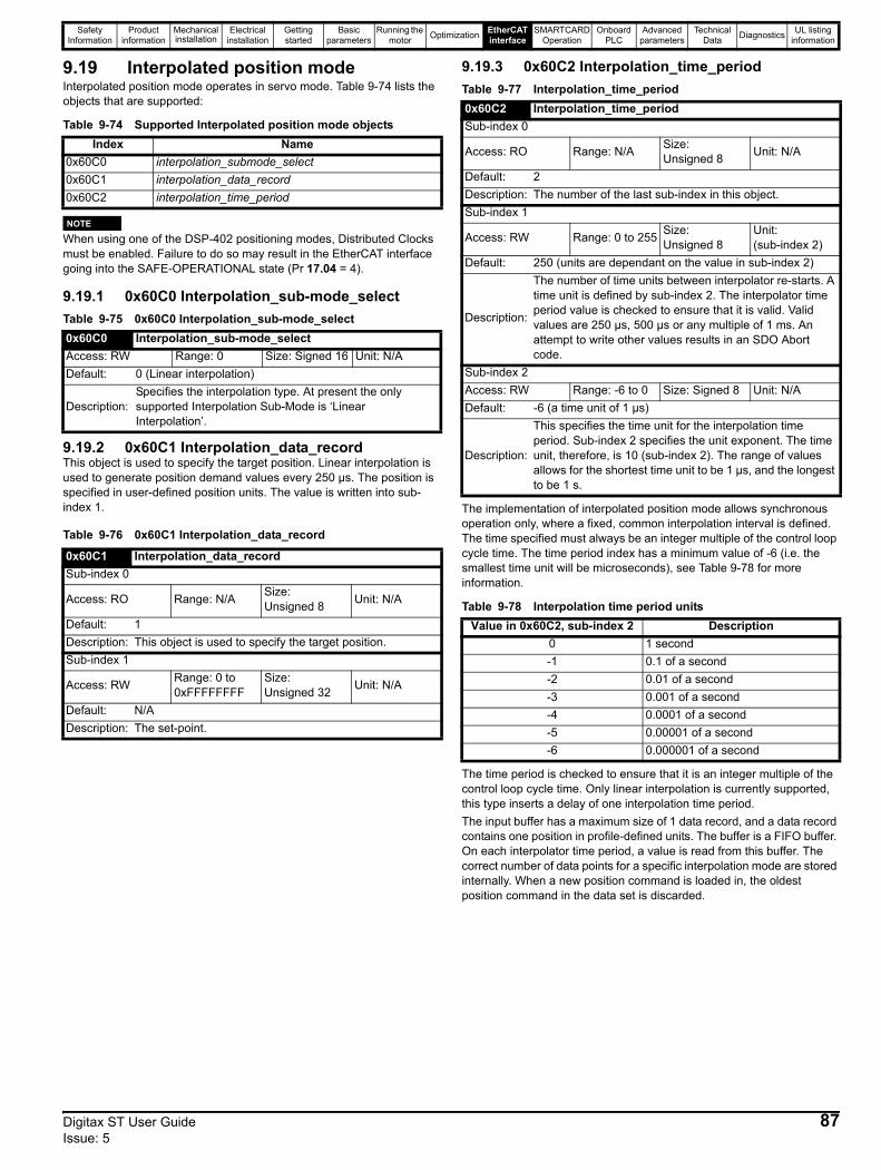
Safety Information
Product information
Mechanical installation
Electrical installation
Getting started
Basic parameters
Running the motor Optimization EtherCAT
interfaceSMARTCARD
OperationOnboard
PLCAdvanced
parametersTechnical
Data Diagnostics UL listing information
9.19 Interpolated position modeInterpolated position mode operates in servo mode. Table 9-74 lists the objects that are supported:
Table 9-74 Supported Interpolated position mode objects
When using one of the DSP-402 positioning modes, Distributed Clocks must be enabled. Failure to do so may result in the EtherCAT interface going into the SAFE-OPERATIONAL state (Pr 17.04 = 4).
9.19.1 0x60C0 Interpolation_sub-mode_selectTable 9-75 0x60C0 Interpolation_sub-mode_select
9.19.2 0x60C1 Interpolation_data_recordThis object is used to specify the target position. Linear interpolation is used to generate position demand values every 250 µs. The position is specified in user-defined position units. The value is written into sub-index 1.
Table 9-76 0x60C1 Interpolation_data_record
9.19.3 0x60C2 Interpolation_time_periodTable 9-77 Interpolation_time_period
The implementation of interpolated position mode allows synchronous operation only, where a fixed, common interpolation interval is defined. The time specified must always be an integer multiple of the control loop cycle time. The time period index has a minimum value of -6 (i.e. the smallest time unit will be microseconds), see Table 9-78 for more information.
Table 9-78 Interpolation time period units
The time period is checked to ensure that it is an integer multiple of the control loop cycle time. Only linear interpolation is currently supported, this type inserts a delay of one interpolation time period.The input buffer has a maximum size of 1 data record, and a data record contains one position in profile-defined units. The buffer is a FIFO buffer. On each interpolator time period, a value is read from this buffer. The correct number of data points for a specific interpolation mode are stored internally. When a new position command is loaded in, the oldest position command in the data set is discarded.
Index Name0x60C0 interpolation_submode_select0x60C1 interpolation_data_record0x60C2 interpolation_time_period
0x60C0 Interpolation_sub-mode_selectAccess: RW Range: 0 Size: Signed 16 Unit: N/ADefault: 0 (Linear interpolation)
Description: Specifies the interpolation type. At present the only supported Interpolation Sub-Mode is ‘Linear Interpolation’.
0x60C1 Interpolation_data_recordSub-index 0
Access: RO Range: N/A Size: Unsigned 8 Unit: N/A
Default: 1Description: This object is used to specify the target position.Sub-index 1
Access: RW Range: 0 to 0xFFFFFFFF
Size: Unsigned 32 Unit: N/A
Default: N/ADescription: The set-point.
NOTE
0x60C2 Interpolation_time_periodSub-index 0
Access: RO Range: N/A Size: Unsigned 8 Unit: N/A
Default: 2Description: The number of the last sub-index in this object.Sub-index 1
Access: RW Range: 0 to 255 Size: Unsigned 8
Unit: (sub-index 2)
Default: 250 (units are dependant on the value in sub-index 2)
Description:
The number of time units between interpolator re-starts. A time unit is defined by sub-index 2. The interpolator time period value is checked to ensure that it is valid. Valid values are 250 µs, 500 µs or any multiple of 1 ms. An attempt to write other values results in an SDO Abort code.
Sub-index 2Access: RW Range: -6 to 0 Size: Signed 8 Unit: N/ADefault: -6 (a time unit of 1 µs)
Description:
This specifies the time unit for the interpolation time period. Sub-index 2 specifies the unit exponent. The time unit, therefore, is 10 (sub-index 2). The range of values allows for the shortest time unit to be 1 µs, and the longest to be 1 s.
Value in 0x60C2, sub-index 2 Description0 1 second-1 0.1 of a second-2 0.01 of a second-3 0.001 of a second-4 0.0001 of a second-5 0.00001 of a second-6 0.000001 of a second
Digitax ST User Guide 87Issue: 5
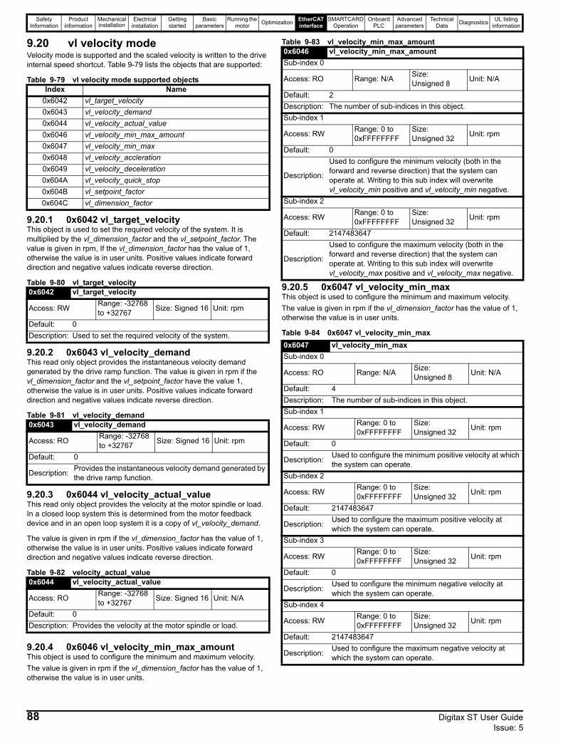
Safety Information
Product information
Mechanical installation
Electrical installation
Getting started
Basic parameters
Running the motor Optimization EtherCAT
interfaceSMARTCARD
OperationOnboard
PLCAdvanced
parametersTechnical
Data Diagnostics UL listing information
9.20 vl velocity modeVelocity mode is supported and the scaled velocity is written to the drive internal speed shortcut. Table 9-79 lists the objects that are supported:
Table 9-79 vl velocity mode supported objects
9.20.1 0x6042 vl_target_velocityThis object is used to set the required velocity of the system. It is multiplied by the vl_dimension_factor and the vl_setpoint_factor. The value is given in rpm, If the vl_dimension_factor has the value of 1, otherwise the value is in user units. Positive values indicate forward direction and negative values indicate reverse direction.
Table 9-80 vl_target_velocity
9.20.2 0x6043 vl_velocity_demandThis read only object provides the instantaneous velocity demand generated by the drive ramp function. The value is given in rpm if the vl_dimension_factor and the vl_setpoint_factor have the value 1, otherwise the value is in user units. Positive values indicate forward direction and negative values indicate reverse direction.
Table 9-81 vl_velocity_demand
9.20.3 0x6044 vl_velocity_actual_valueThis read only object provides the velocity at the motor spindle or load. In a closed loop system this is determined from the motor feedback device and in an open loop system it is a copy of vl_velocity_demand.
The value is given in rpm if the vl_dimension_factor has the value of 1, otherwise the value is in user units. Positive values indicate forward direction and negative values indicate reverse direction.
Table 9-82 velocity_actual_value
9.20.4 0x6046 vl_velocity_min_max_amountThis object is used to configure the minimum and maximum velocity. The value is given in rpm if the vl_dimension_factor has the value of 1, otherwise the value is in user units.
Table 9-83 vl_velocity_min_max_amount
9.20.5 0x6047 vl_velocity_min_maxThis object is used to configure the minimum and maximum velocity. The value is given in rpm if the vl_dimension_factor has the value of 1, otherwise the value is in user units.
Table 9-84 0x6047 vl_velocity_min_max
Index Name0x6042 vl_target_velocity0x6043 vl_velocity_demand0x6044 vl_velocity_actual_value0x6046 vl_velocity_min_max_amount0x6047 vl_velocity_min_max0x6048 vl_velocity_accleration0x6049 vl_velocity_deceleration0x604A vl_velocity_quick_stop0x604B vl_setpoint_factor0x604C vl_dimension_factor
0x6042 vl_target_velocity
Access: RW Range: -32768 to +32767 Size: Signed 16 Unit: rpm
Default: 0Description: Used to set the required velocity of the system.
0x6043 vl_velocity_demand
Access: RO Range: -32768 to +32767 Size: Signed 16 Unit: rpm
Default: 0
Description: Provides the instantaneous velocity demand generated by the drive ramp function.
0x6044 vl_velocity_actual_value
Access: RO Range: -32768 to +32767 Size: Signed 16 Unit: N/A
Default: 0Description: Provides the velocity at the motor spindle or load.
0x6046 vl_velocity_min_max_amountSub-index 0
Access: RO Range: N/A Size: Unsigned 8 Unit: N/A
Default: 2Description: The number of sub-indices in this object.Sub-index 1
Access: RW Range: 0 to 0xFFFFFFFF
Size: Unsigned 32 Unit: rpm
Default: 0
Description:
Used to configure the minimum velocity (both in the forward and reverse direction) that the system can operate at. Writing to this sub index will overwrite vl_velocity_min positive and vl_velocity_min negative.
Sub-index 2
Access: RW Range: 0 to 0xFFFFFFFF
Size: Unsigned 32 Unit: rpm
Default: 2147483647
Description:
Used to configure the maximum velocity (both in the forward and reverse direction) that the system can operate at. Writing to this sub index will overwrite vl_velocity_max positive and vl_velocity_max negative.
0x6047 vl_velocity_min_maxSub-index 0
Access: RO Range: N/A Size: Unsigned 8 Unit: N/A
Default: 4Description: The number of sub-indices in this object.Sub-index 1
Access: RW Range: 0 to 0xFFFFFFFF
Size: Unsigned 32 Unit: rpm
Default: 0
Description: Used to configure the minimum positive velocity at which the system can operate.
Sub-index 2
Access: RW Range: 0 to 0xFFFFFFFF
Size: Unsigned 32 Unit: rpm
Default: 2147483647
Description: Used to configure the maximum positive velocity at which the system can operate.
Sub-index 3
Access: RW Range: 0 to 0xFFFFFFFF
Size: Unsigned 32 Unit: rpm
Default: 0
Description: Used to configure the minimum negative velocity at which the system can operate.
Sub-index 4
Access: RW Range: 0 to 0xFFFFFFFF
Size: Unsigned 32 Unit: rpm
Default: 2147483647
Description: Used to configure the maximum negative velocity at which the system can operate.
88 Digitax ST User Guide Issue: 5

Safety Information
Product information
Mechanical installation
Electrical installation
Getting started
Basic parameters
Running the motor Optimization EtherCAT
interfaceSMARTCARD
OperationOnboard
PLCAdvanced
parametersTechnical
Data Diagnostics UL listing information
9.20.6 0x6048 vl_velocity_accelerationThis object is used to configure the delta speed and delta time of the slope of the acceleration ramp.
Example: To ramp to 1000 rpm in 5s, possible values for delta speed and delta time are 10000 and 50 respectively.
vl_velocity_acceleration = delta speed / delta time
Table 9-85 0x6048 vl_velocity_acceleration
9.20.7 0x6049 vl_velocity_decelerationThis object is used to configure the delta speed and delta time of the slope of the deceleration ramp.
Example: To decelerate by 800 rpm in 10s, possible values for delta speed and delta time are 8000 and 100 respectively.
vl_velocity_deceleration = delta speed / delta time
Table 9-86 0x6049 vl_velocity_deceleration
9.20.8 0x604A vl_velocity_quick_stopThis object is used to configure the delta speed and delta time of the slope of the deceleration ramp for quick stop.
Example: To decelerate by 800 rpm in 10 s, possible values for delta speed and delta time are 8000 and 100 respectively.
vl velocity deceleration = delta speed / delta time
Table 9-87 0x604A vl_velocity_quick_stop
9.20.9 0x604B vl_setpoint_factorThis object is used to configure the numerator and denominator of the vl_setpoint_factor. The vl_setpoint_factor modifies the resolution or directing range of the specified setpoint. It does not influence the velocity limit function and the ramp function. A value of 0 must not be used.
Table 9-88 0x604B vl_setpoint_factor
9.20.10 0x604C vl_dimension_factorThis object is used to configure the numerator and denominator of the vl_dimension_factor. The vl_dimension_factor is used to scale the user units so that they can be used in a way that relates to the specific application.
Calculating the vl_dimension_factor: Every user-specific velocity consists of a specific unit referred to as a specific unit of time (e.g. 1/s, bottles/min, m/s,...). The purpose of the vl_dimension_factor is to convert this specific unit to the revolutions/minute unit. A value of 0 must not be used.
Velocity [user-defined unit] / Dimension factor [rpm/user-defined unit] = Velocity [rpm]
0x6048 vl_velocity_accelerationSub-index 0
Access: RO Range: N/A Size: Unsigned 8 Unit: N/A
Default: 2Description: The number of sub-indices in this object.Sub-index 1
Access: RW Range: 0 to 0xFFFFFFFF
Size: Unsigned 32 Unit: rpm
Default: 1000
Description: The value of delta speed is given in rpm if the vl_dimension_factor and the vl_setpoint_factor have the value 1, otherwise the value is in user units.
Sub-index 2
Access: RW Range: 0 to 65535
Size: Unsigned 16 Unit: s
Default: 2Description: The value of delta time is given in seconds.
0x6049 vl_velocity_decelerationSub-index 0
Access: RO Range: N/A Size: Unsigned 8 Unit: N/A
Default: 2Description: The number of sub-indices in this object.Sub-index 1
Access: RW Range: 0 to 0xFFFFFFFF
Size: Unsigned 32 Unit: rpm
Default: 1000
Description: The value of delta speed is given in rpm if the vl_dimension_factor and the vl_setpoint_factor have the value 1, otherwise the value is in user units.
Sub-index 2
Access: RW Range: 0 to 65535
Size: Unsigned 16 Unit: s
Default: 2Description: The value of delta time is given in seconds.
0x604A vl_velocity_quick_stopSub-index 0
Access: RO Range: N/A Size: Unsigned 8 Unit: N/A
Default: 2Description: The number of sub-indices in this object.Sub-index 1
Access: RW Range: 0 to 0xFFFFFFFF
Size: Unsigned 32 Unit: rpm
Default: 1000
Description: The value of delta speed is given in rpm if the vl_dimension_factor and the vl_setpoint_factor have the value 1, otherwise the value is in user units.
Sub-index 2
Access: RW Range: 0 to 65535
Size: Unsigned 16 Unit: s
Default: 2Description: The value of delta time is given in seconds.
0x604B vl_setpoint_factorSub-index 0
Access: RO Range: N/A Size: Unsigned 8 Unit: N/A
Default: 2Description: The number of sub-indices in this object.Sub-index 1
Access: RW Range: -32768 to +32767 Size: Signed 16 Unit: N/A
Default: 1Description: vl_setpoint_factor numerator (a value of 0 is not valid).Sub-index 2
Access: RW Range: -32768 to +32767 Size: Signed 16 Unit: N/A
Default: 1Description: vl_setpoint_factor denominator (a value of 0 is not valid).
Digitax ST User Guide 89Issue: 5
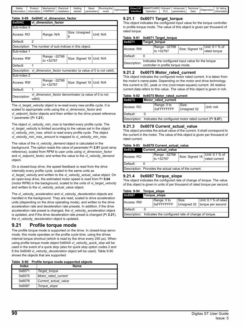
Safety Information
Product information
Mechanical installation
Electrical installation
Getting started
Basic parameters
Running the motor Optimization EtherCAT
interfaceSMARTCARD
OperationOnboard
PLCAdvanced
parametersTechnical
Data Diagnostics UL listing information
Table 9-89 0x604C vl_dimension_factor
The vl_target_velocity object is re-read every new profile cycle. It is scaled to appropriate units using the vl_dimension_factor and vl_setpoint_factor objects and then written to the drive preset reference 1 parameter (Pr 1.21).
The object vl_velocity_min_max is handled every profile cycle. The vl_target_velocity is limited according to the values set in the object vl_velocity_min_max, which is read every profile cycle. The object vl_velocity_min_max_amount is mapped to vl_velocity_min_max.
The value of the vl_velocity_demand object is calculated in the background. The option reads the value of parameter Pr 2.01 (post ramp reference), scaled from RPM to user units using vl_dimension_factor and vl_setpoint_factor, and writes the value to the vl_velocity_demand object.
On a closed-loop drive, the speed feedback is read from the drive internally every profile cycle, scaled to the same units as vl_target_velocity and written to the vl_velocity_actual_value object. On an open-loop drive, the estimated motor speed is read from Pr 5.04 (motor RPM) in the background, scaled to the units of vl_target_velocity and written to the vl_velocity_actual_value object.
The vl_velocity_acceleration and vl_velocity_deceleration objects are handled in the background. They are read, scaled to drive acceleration units (depending on the drive operating mode), and written to the drive acceleration rate and deceleration rate presets. In addition, if the drive acceleration rate preset is changed, the vl_velocity_acceleration object is updated, and if the drive deceleration rate preset is changed (Pr 2.21), the vl_velocity_deceleration object is updated.
9.21 Profile torque modeThe profile torque mode is supported on the drive. In closed-loop servo mode, this mode operates on the profile cycle time, using the drives internal torque shortcut (which is read by the drive every 250 µs). When using profile torque mode object 0x604A vl_velocity_quick_stop will be used in the event of a quick stop (also for quick stop option codes 2 and 6 the 0x6049 vl_velocity_deceleration object will be used). Table 9-90 shows the objects that are supported:
Table 9-90 Profile torque mode supported objects
9.21.1 0x6071 Target_torqueThis object indicates the configured input value for the torque controller in profile torque mode. The value of this object is given per thousand of rated torque.
Table 9-91 0x6071 Target_torque
9.21.2 0x6075 Motor_rated_currentThis object indicates the configured motor rated current. It is taken from the motor’s name-plate. Depending on the motor and drive technology this current is DC, peak or rms (root-mean-square) current. All relative current data refers to this value. The value of this object is given in mA.
Table 9-92 0x6075 Motor_rated_current
9.21.3 0x6078 Current_actual_valueThis object provides the actual value of the current. It shall correspond to the current in the motor. The value of this object is given per thousand of rated current.
Table 9-93 0x6078 Current_actual_value
9.21.4 0x6087 Torque_slopeThis object indicates the configured rate of change of torque. The value of this object is given in units of per thousand of rated torque per second.
Table 9-94 Torque_slope
0x604C vl_dimension_factorSub-index 0
Access: RO Range: N/A Size: Unsigned 8 Unit: N/A
Default: 2Description: The number of sub-indices in this object.Sub-index 1
Access: RW Range: -32768 to +32767 Size: Signed 16 Unit: N/A
Default: 1Description: vl_dimension_factor numerator (a value of 0 is not valid).Sub-index 2
Access: RW Range: -32768 to +32767 Size: Signed 16 Unit: N/A
Default: 1
Description: vl_dimension_factor denominator (a value of 0 is not valid).
Index Name0x6071 Target_torque0x6075 Motor_rated_current0x6078 Current_actual_value0x6087 Torque_slope
0x6071 Target_torque
Access: RW Range: -32768 to +32767 Size: Signed 16 Unit: 0.1 % of
rated torqueDefault: 0
Description: Indicates the configured input value for the torque controller in profile torque mode.
0x6075 Motor_rated_current
Access: RO Range: 0 to 0xFFFFFFFF
Size: Unsigned 32 Unit: mA
Default: 0Description: Indicates the configured motor rated current (Pr 5.07).
0x6078 Current_actual_value
Access: RO Range: -32768 to +32767 Size: Signed 16 Unit: 0.1 % of
rated currentDefault: 0Description: Provides the actual value of the current.
0x6087 Torque_slope
Access: RW Range: 0 to 0xFFFFFFFF
Size: Unsigned 32
Unit: 0.1 % of rated torque per second
Default: 0Description: Indicates the configured rate of change of torque.
90 Digitax ST User Guide Issue: 5
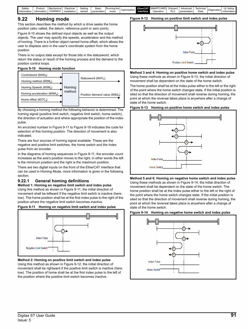
Safety Information
Product information
Mechanical installation
Electrical installation
Getting started
Basic parameters
Running the motor Optimization EtherCAT
interfaceSMARTCARD
OperationOnboard
PLCAdvanced
parametersTechnical
Data Diagnostics UL listing information
9.22 Homing modeThis section describes the method by which a drive seeks the home position (also called, the datum, reference point or zero point).Figure 9-10 shows the defined input objects as well as the output objects. The user may specify the speeds, acceleration and the method of homing. There is a further object named home offset, which allows the user to displace zero in the user's coordinate system from the home position.There is no output data except for those bits in the statusword, which return the status or result of the homing process and the demand to the position control loops.Figure 9-10 Homing mode function
By choosing a homing method the following behavior is determined: The homing signal (positive limit switch, negative limit switch, home switch), the direction of actuation and where appropriate the position of the index pulse.An encircled number in Figure 9-11 to Figure 9-18 indicates the code for selection of this homing position. The direction of movement is also indicated.There are four sources of homing signal available: These are the negative and positive limit switches, the home switch and the index pulse from an encoder. In the diagrams of homing sequences in Figure 9-11, the encoder count increases as the axis's position moves to the right, in other words the left is the minimum position and the right is the maximum position. There are two digital inputs on the front of the EtherCAT interface that can be used in Homing Mode, more information is given in the following section.
9.22.1 General homing definitionsMethod 1: Homing on negative limit switch and index pulseUsing this method as shown in Figure 9-11, the initial direction of movement shall be leftward if the negative limit switch is inactive (here: low). The home position shall be at the first index pulse to the right of the position where the negative limit switch becomes inactive.Figure 9-11 Homing on negative limit switch and index pulse
Method 2: Homing on positive limit switch and index pulseUsing this method as shown in Figure 9-12, the initial direction of movement shall be rightward if the positive limit switch is inactive (here: low). The position of home shall be at the first index pulse to the left of the position where the positive limit switch becomes inactive.
Figure 9-12 Homing on positive limit switch and index pulse
Method 3 and 4: Homing on positive home switch and index pulseUsing these methods as shown in Figure 9-13, the initial direction of movement shall be dependent on the state of the home switch. The home position shall be at the index pulse either to the left or the right of the point where the home switch changes state. If the initial position is sited so that the direction of movement shall reverse during homing, the point at which the reversal takes place is anywhere after a change of state of the home switch.Figure 9-13 Homing on positive home switch and index pulse
Method 5 and 6: Homing on negative home switch and index pulseUsing these methods as shown in Figure 9-14, the initial direction of movement shall be dependent on the state of the home switch. The home position shall be at the index pulse either to the left or the right of the point where the home switch changes state. If the initial position is sited so that the direction of movement shall reverse during homing, the point at which the reversal takes place is anywhere after a change of state of the home switch.Figure 9-14 Homing on negative home switch and index pulse
Homingmethod
Statusword (6041 )h
Position demand value (6062 )h
Controlword (6040 )
Homing method (6098 )
Homing Speeds (6099 )
Homing acceleration (609A )
Home offset (607C )
h
h
h
h
h
Digitax ST User Guide 91Issue: 5
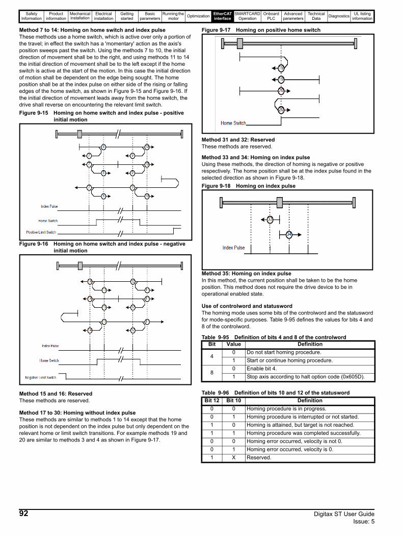
Safety Information
Product information
Mechanical installation
Electrical installation
Getting started
Basic parameters
Running the motor Optimization EtherCAT
interfaceSMARTCARD
OperationOnboard
PLCAdvanced
parametersTechnical
Data Diagnostics UL listing information
Method 7 to 14: Homing on home switch and index pulseThese methods use a home switch, which is active over only a portion of the travel; in effect the switch has a 'momentary' action as the axis's position sweeps past the switch. Using the methods 7 to 10, the initial direction of movement shall be to the right, and using methods 11 to 14 the initial direction of movement shall be to the left except if the home switch is active at the start of the motion. In this case the initial direction of motion shall be dependent on the edge being sought. The home position shall be at the index pulse on either side of the rising or falling edges of the home switch, as shown in Figure 9-15 and Figure 9-16. If the initial direction of movement leads away from the home switch, the drive shall reverse on encountering the relevant limit switch.Figure 9-15 Homing on home switch and index pulse - positive
initial motion
Figure 9-16 Homing on home switch and index pulse - negative initial motion
Method 15 and 16: ReservedThese methods are reserved.
Method 17 to 30: Homing without index pulseThese methods are similar to methods 1 to 14 except that the home position is not dependent on the index pulse but only dependent on the relevant home or limit switch transitions. For example methods 19 and 20 are similar to methods 3 and 4 as shown in Figure 9-17.
Figure 9-17 Homing on positive home switch
Method 31 and 32: ReservedThese methods are reserved.
Method 33 and 34: Homing on index pulseUsing these methods, the direction of homing is negative or positive respectively. The home position shall be at the index pulse found in the selected direction as shown in Figure 9-18.Figure 9-18 Homing on index pulse
Method 35: Homing on index pulseIn this method, the current position shall be taken to be the home position. This method does not require the drive device to be in operational enabled state.
Use of controlword and statuswordThe homing mode uses some bits of the controlword and the statusword for mode-specific purposes. Table 9-95 defines the values for bits 4 and 8 of the controlword.
Table 9-95 Definition of bits 4 and 8 of the controlword
Table 9-96 Definition of bits 10 and 12 of the statusword
Bit Value Definition
40 Do not start homing procedure.1 Start or continue homing procedure.
80 Enable bit 4.1 Stop axis according to halt option code (0x605D).
Bit 12 Bit 10 Definition0 0 Homing procedure is in progress.0 1 Homing procedure is interrupted or not started.1 0 Homing is attained, but target is not reached.1 1 Homing procedure was completed successfully.0 0 Homing error occurred, velocity is not 0.0 1 Homing error occurred, velocity is 0.1 X Reserved.
92 Digitax ST User Guide Issue: 5

Safety Information
Product information
Mechanical installation
Electrical installation
Getting started
Basic parameters
Running the motor Optimization EtherCAT
interfaceSMARTCARD
OperationOnboard
PLCAdvanced
parametersTechnical
Data Diagnostics UL listing information
9.22.2 Homing mode object definitions0x2803 Homing sourceThis object indicates the configured source of the homing switch used during the homing procedure. Table 9-97 specifies the object description.
Table 9-97 Homing source
0x2804 Freeze objectThis object is used to configure the freeze function that can be used within the Homing mode profile. Table 9-98 specifies the object description.
Table 9-98 Freeze object
0x607C Home offsetThis object indicates the configured difference between the zero position for the application and the machine home position (found during homing). During homing the machine home position is found and once the homing is completed, the zero position is offset from the home position by adding the home offset to the home position. All subsequent absolute moves shall be taken relative to this new zero position. This is illustrated in Figure 9-19. The value of this object shall be given in user-
defined position units. Negative values indicate the opposite direction.Figure 9-19 Home offset definition
Table 9-99 Home offset
0x6098 Homing methodThis object indicates the configured homing method that shall be used. Table 9-100 specifies the object description, and Table 9-101 specifies the value ranges for this object.
Table 9-100 Homing method
Table 9-101 Homing method values
0x6099 Homing speedsThis object indicates the configured speeds used during the homing procedure. The values shall be given in user-defined velocity units. Table 9-102 specifies the object description.
Table 9-102 Homing speeds
0x609A Homing accelerationThis object indicates the configured acceleration and deceleration to be used during the homing operation. The value shall be given in user-defined acceleration units. Table 9-103 specifies the object description.
0x2803 Homing sourceSub-index 0
Access: RO Range: N/A Size: Unsigned 8 Unit: N/A
Default: 2Description: The number of the last sub-index in this object.Sub-index 1Access: RW Range: 1 to 8 Size:
Unsigned 8 Unit: N/A
Default: 5Description: The source of the homing switch. This will specify a digital input as follows: 1 to 6 - The number of a drive digital input 7 to 8 - EtherCAT interface digital input 0 or 1Sub-index 2Access: RW Range: 0 to 1 Size: Unsigned
8 Unit: N/A
Default: 0Description: Use the feedback source freeze for homing. This will cause the freeze from the selected feedback device to be used instead of the index (marker) pulse when it is required during homing.
0x2804 Freeze objectSub-index 0
Access: RO Range: N/A Size: Unsigned 8 Unit: N/A
Default: 2Description: The number of the last sub-index in this object.Sub-index 1Access: RW Range: 0 to 1 Size:
Unsigned 8 Unit: N/A
Default: 0Description: Route the option freeze onto the drive. Setting a value of 1 here will route the option digital input 0 onto the drive freeze line.Sub-index 2Access: RW Range: 0 to 1 Size:
Unsigned 8 Unit: N/A
Default: 0Description: Option to drive freeze invert. Setting a value of 1 will invert the freeze signal routed onto the drive from the option input 0 (if 0x2804, sub-index 1 is set to 1). This value will be read only on a transition from 0 to 1 in sub-index 1.
0x607C Home offset
Access: RW Range: 0 to 0xFFFFFFFF Size: Signed 32
Unit: User-defined position units
Default: 0Description: Homing offset value.
0x6098 Homing method
Access: RW Range: 0 - 35 Size: Unsigned 8 Unit: N/A
Default: 0Description: The homing method that shall be used.
Value Definition0 No homing method assigned1 Method 1 shall be used
to34 Method 34 shall be used35 Method 35 shall be used
0x6099 Homing speedsSub-index 0Access: RO Range: 2 Size: Signed 8 Unit: N/ADefault: 2Description: The number of the last sub-index in this object.Sub-index 1Access: RW
Range: 0 to 0xFFFFFFFF
Size: Unsigned 32 Unit: N/A
Default: 0Description: Speed during search for a switch.Sub-index 2Access: RW
Range: 0 to 0xFFFFFFFF
Size: Unsigned 32 Unit: N/A
Default: 0Description: Speed during search for a zero.
Home offset
Homeposition
Zeroposition
Digitax ST User Guide 93Issue: 5
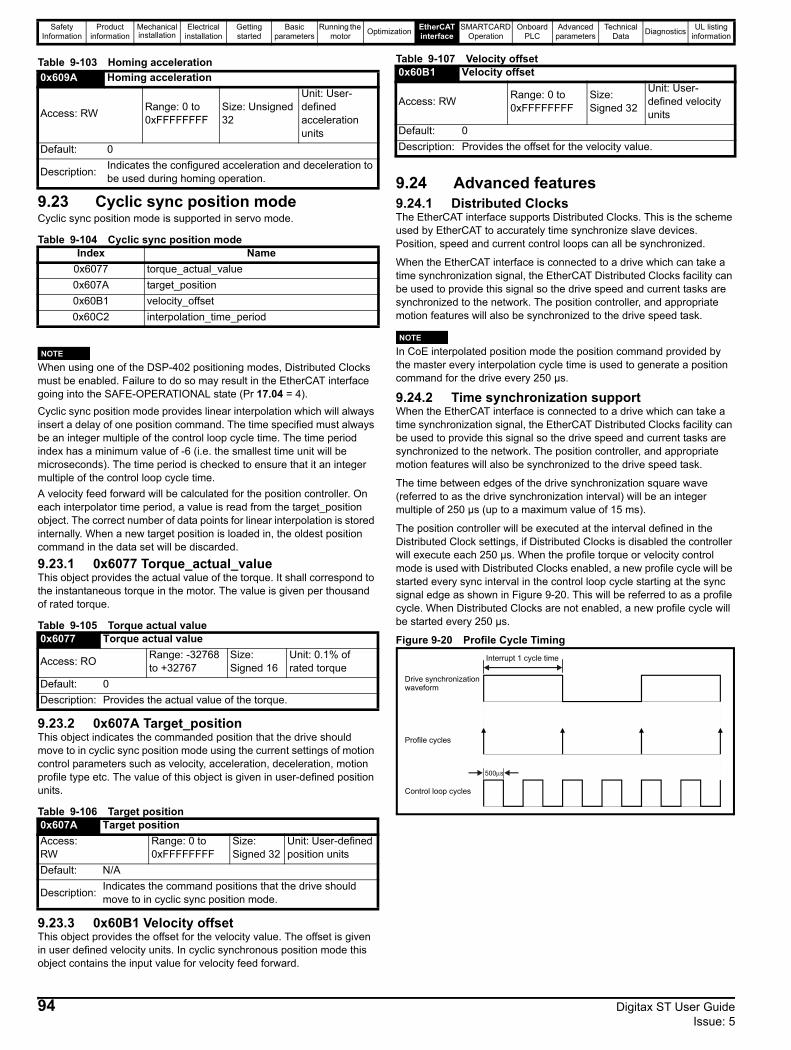
Safety Information
Product information
Mechanical installation
Electrical installation
Getting started
Basic parameters
Running the motor Optimization EtherCAT
interfaceSMARTCARD
OperationOnboard
PLCAdvanced
parametersTechnical
Data Diagnostics UL listing information
Table 9-103 Homing acceleration
9.23 Cyclic sync position modeCyclic sync position mode is supported in servo mode.
Table 9-104 Cyclic sync position mode
When using one of the DSP-402 positioning modes, Distributed Clocks must be enabled. Failure to do so may result in the EtherCAT interface going into the SAFE-OPERATIONAL state (Pr 17.04 = 4).Cyclic sync position mode provides linear interpolation which will always insert a delay of one position command. The time specified must always be an integer multiple of the control loop cycle time. The time period index has a minimum value of -6 (i.e. the smallest time unit will be microseconds). The time period is checked to ensure that it an integer multiple of the control loop cycle time. A velocity feed forward will be calculated for the position controller. On each interpolator time period, a value is read from the target_position object. The correct number of data points for linear interpolation is stored internally. When a new target position is loaded in, the oldest position command in the data set will be discarded.
9.23.1 0x6077 Torque_actual_valueThis object provides the actual value of the torque. It shall correspond to the instantaneous torque in the motor. The value is given per thousand of rated torque.
Table 9-105 Torque actual value
9.23.2 0x607A Target_positionThis object indicates the commanded position that the drive should move to in cyclic sync position mode using the current settings of motion control parameters such as velocity, acceleration, deceleration, motion profile type etc. The value of this object is given in user-defined position units.
Table 9-106 Target position
9.23.3 0x60B1 Velocity offsetThis object provides the offset for the velocity value. The offset is given in user defined velocity units. In cyclic synchronous position mode this object contains the input value for velocity feed forward.
Table 9-107 Velocity offset
9.24 Advanced features9.24.1 Distributed ClocksThe EtherCAT interface supports Distributed Clocks. This is the scheme used by EtherCAT to accurately time synchronize slave devices. Position, speed and current control loops can all be synchronized.
When the EtherCAT interface is connected to a drive which can take a time synchronization signal, the EtherCAT Distributed Clocks facility can be used to provide this signal so the drive speed and current tasks are synchronized to the network. The position controller, and appropriate motion features will also be synchronized to the drive speed task.
In CoE interpolated position mode the position command provided by the master every interpolation cycle time is used to generate a position command for the drive every 250 µs.
9.24.2 Time synchronization supportWhen the EtherCAT interface is connected to a drive which can take a time synchronization signal, the EtherCAT Distributed Clocks facility can be used to provide this signal so the drive speed and current tasks are synchronized to the network. The position controller, and appropriate motion features will also be synchronized to the drive speed task.
The time between edges of the drive synchronization square wave (referred to as the drive synchronization interval) will be an integer multiple of 250 µs (up to a maximum value of 15 ms).
The position controller will be executed at the interval defined in the Distributed Clock settings, if Distributed Clocks is disabled the controller will execute each 250 µs. When the profile torque or velocity control mode is used with Distributed Clocks enabled, a new profile cycle will be started every sync interval in the control loop cycle starting at the sync signal edge as shown in Figure 9-20. This will be referred to as a profile cycle. When Distributed Clocks are not enabled, a new profile cycle will be started every 250 µs.
Figure 9-20 Profile Cycle Timing
0x609A Homing acceleration
Access: RW Range: 0 to 0xFFFFFFFF
Size: Unsigned 32
Unit: User-defined acceleration units
Default: 0
Description: Indicates the configured acceleration and deceleration to be used during homing operation.
Index Name0x6077 torque_actual_value0x607A target_position0x60B1 velocity_offset0x60C2 interpolation_time_period
0x6077 Torque actual value
Access: RO Range: -32768 to +32767
Size: Signed 16
Unit: 0.1% of rated torque
Default: 0Description: Provides the actual value of the torque.
0x607A Target positionAccess: RW
Range: 0 to 0xFFFFFFFF
Size: Signed 32
Unit: User-defined position units
Default: N/A
Description: Indicates the command positions that the drive should move to in cyclic sync position mode.
NOTE
0x60B1 Velocity offset
Access: RW Range: 0 to 0xFFFFFFFF
Size: Signed 32
Unit: User-defined velocity units
Default: 0Description: Provides the offset for the velocity value.
NOTE
Interrupt 1 cycle time
500μs
Drive synchronizationwaveform
Control loop cycles
Profile cycles
94 Digitax ST User Guide Issue: 5
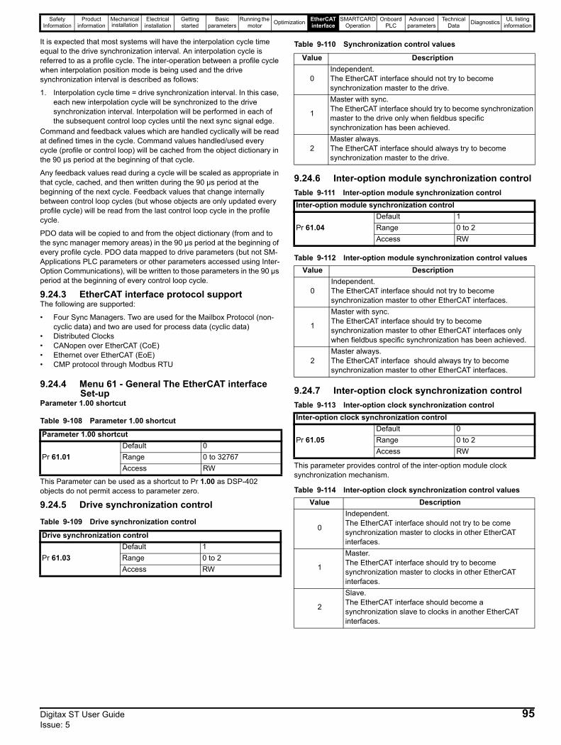
Safety Information
Product information
Mechanical installation
Electrical installation
Getting started
Basic parameters
Running the motor Optimization EtherCAT
interfaceSMARTCARD
OperationOnboard
PLCAdvanced
parametersTechnical
Data Diagnostics UL listing information
It is expected that most systems will have the interpolation cycle time equal to the drive synchronization interval. An interpolation cycle is referred to as a profile cycle. The inter-operation between a profile cycle when interpolation position mode is being used and the drive synchronization interval is described as follows:
1. Interpolation cycle time = drive synchronization interval. In this case, each new interpolation cycle will be synchronized to the drive synchronization interval. Interpolation will be performed in each of the subsequent control loop cycles until the next sync signal edge.
Command and feedback values which are handled cyclically will be read at defined times in the cycle. Command values handled/used every cycle (profile or control loop) will be cached from the object dictionary in the 90 µs period at the beginning of that cycle.
Any feedback values read during a cycle will be scaled as appropriate in that cycle, cached, and then written during the 90 µs period at the beginning of the next cycle. Feedback values that change internally between control loop cycles (but whose objects are only updated every profile cycle) will be read from the last control loop cycle in the profile cycle.
PDO data will be copied to and from the object dictionary (from and to the sync manager memory areas) in the 90 µs period at the beginning of every profile cycle. PDO data mapped to drive parameters (but not SM-Applications PLC parameters or other parameters accessed using Inter-Option Communications), will be written to those parameters in the 90 µs period at the beginning of every control loop cycle.
9.24.3 EtherCAT interface protocol supportThe following are supported:
• Four Sync Managers. Two are used for the Mailbox Protocol (non-cyclic data) and two are used for process data (cyclic data)
• Distributed Clocks • CANopen over EtherCAT (CoE)• Ethernet over EtherCAT (EoE) • CMP protocol through Modbus RTU
9.24.4 Menu 61 - General The EtherCAT interface Set-up
Parameter 1.00 shortcut
Table 9-108 Parameter 1.00 shortcut
This Parameter can be used as a shortcut to Pr 1.00 as DSP-402 objects do not permit access to parameter zero.
9.24.5 Drive synchronization controlTable 9-109 Drive synchronization control
Table 9-110 Synchronization control values
9.24.6 Inter-option module synchronization controlTable 9-111 Inter-option module synchronization control
Table 9-112 Inter-option module synchronization control values
9.24.7 Inter-option clock synchronization controlTable 9-113 Inter-option clock synchronization control
This parameter provides control of the inter-option module clock synchronization mechanism.
Table 9-114 Inter-option clock synchronization control values
Parameter 1.00 shortcut
Pr 61.01Default 0Range 0 to 32767Access RW
Drive synchronization control
Pr 61.03Default 1Range 0 to 2Access RW
Value Description
0Independent.The EtherCAT interface should not try to become synchronization master to the drive.
1
Master with sync.The EtherCAT interface should try to become synchronization master to the drive only when fieldbus specific synchronization has been achieved.
2Master always.The EtherCAT interface should always try to become synchronization master to the drive.
Inter-option module synchronization control
Pr 61.04Default 1Range 0 to 2Access RW
Value Description
0Independent.The EtherCAT interface should not try to become synchronization master to other EtherCAT interfaces.
1
Master with sync.The EtherCAT interface should try to become synchronization master to other EtherCAT interfaces only when fieldbus specific synchronization has been achieved.
2Master always.The EtherCAT interface should always try to become synchronization master to other EtherCAT interfaces.
Inter-option clock synchronization control
Pr 61.05Default 0Range 0 to 2Access RW
Value Description
0
Independent.The EtherCAT interface should not try to be come synchronization master to clocks in other EtherCAT interfaces.
1
Master.The EtherCAT interface should try to become synchronization master to clocks in other EtherCAT interfaces.
2
Slave.The EtherCAT interface should become a synchronization slave to clocks in another EtherCAT interfaces.
Digitax ST User Guide 95Issue: 5
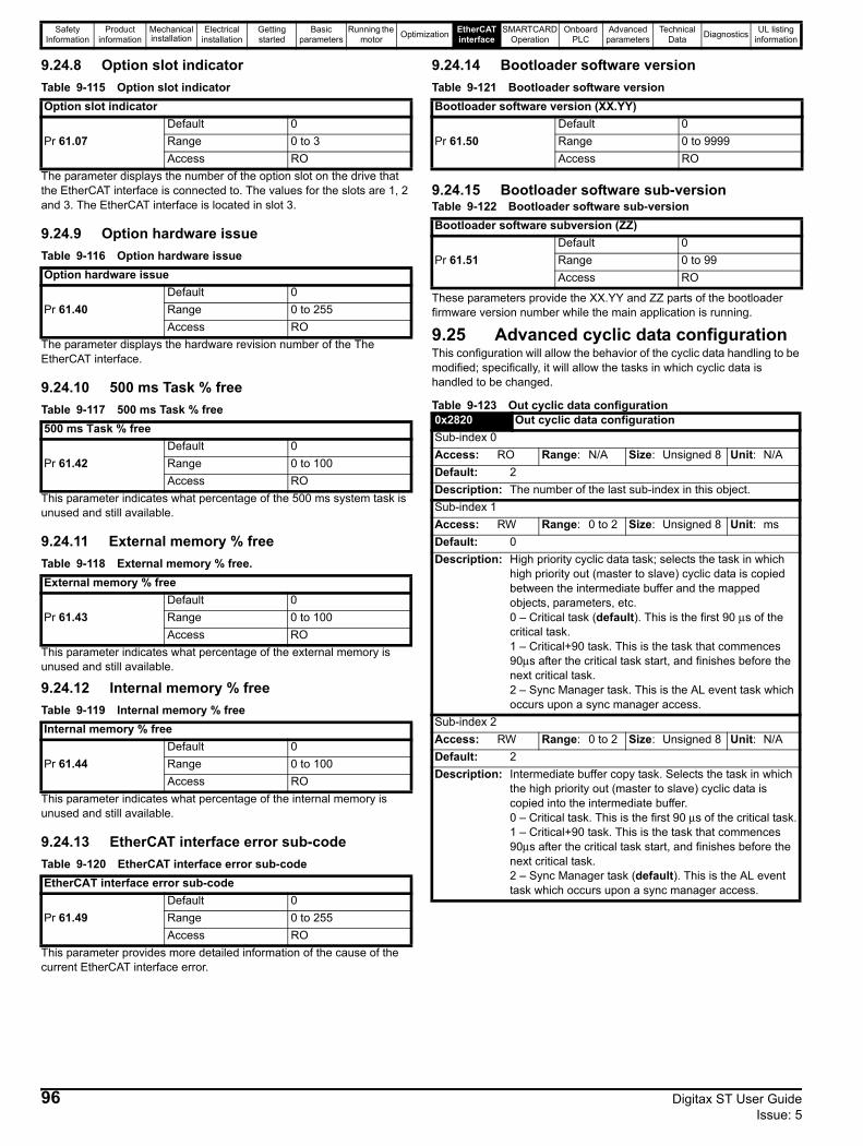
Safety Information
Product information
Mechanical installation
Electrical installation
Getting started
Basic parameters
Running the motor Optimization EtherCAT
interfaceSMARTCARD
OperationOnboard
PLCAdvanced
parametersTechnical
Data Diagnostics UL listing information
9.24.8 Option slot indicatorTable 9-115 Option slot indicator
The parameter displays the number of the option slot on the drive that the EtherCAT interface is connected to. The values for the slots are 1, 2 and 3. The EtherCAT interface is located in slot 3.
9.24.9 Option hardware issueTable 9-116 Option hardware issue
The parameter displays the hardware revision number of the The EtherCAT interface.
9.24.10 500 ms Task % freeTable 9-117 500 ms Task % free
This parameter indicates what percentage of the 500 ms system task is unused and still available.
9.24.11 External memory % freeTable 9-118 External memory % free.
This parameter indicates what percentage of the external memory is unused and still available.
9.24.12 Internal memory % freeTable 9-119 Internal memory % free
This parameter indicates what percentage of the internal memory is unused and still available.
9.24.13 EtherCAT interface error sub-codeTable 9-120 EtherCAT interface error sub-code
This parameter provides more detailed information of the cause of the current EtherCAT interface error.
9.24.14 Bootloader software versionTable 9-121 Bootloader software version
9.24.15 Bootloader software sub-versionTable 9-122 Bootloader software sub-version
These parameters provide the XX.YY and ZZ parts of the bootloader firmware version number while the main application is running.
9.25 Advanced cyclic data configurationThis configuration will allow the behavior of the cyclic data handling to be modified; specifically, it will allow the tasks in which cyclic data is handled to be changed.
Table 9-123 Out cyclic data configuration
Option slot indicator
Pr 61.07Default 0Range 0 to 3Access RO
Option hardware issue
Pr 61.40Default 0Range 0 to 255Access RO
500 ms Task % free
Pr 61.42Default 0Range 0 to 100Access RO
External memory % free
Pr 61.43Default 0Range 0 to 100Access RO
Internal memory % free
Pr 61.44Default 0Range 0 to 100Access RO
EtherCAT interface error sub-code
Pr 61.49Default 0Range 0 to 255Access RO
Bootloader software version (XX.YY)
Pr 61.50Default 0Range 0 to 9999Access RO
Bootloader software subversion (ZZ)
Pr 61.51Default 0Range 0 to 99Access RO
0x2820 Out cyclic data configurationSub-index 0Access: RO Range: N/A Size: Unsigned 8 Unit: N/ADefault: 2Description: The number of the last sub-index in this object.Sub-index 1Access: RW Range: 0 to 2 Size: Unsigned 8 Unit: msDefault: 0Description: High priority cyclic data task; selects the task in which
high priority out (master to slave) cyclic data is copied between the intermediate buffer and the mapped objects, parameters, etc.0 – Critical task (default). This is the first 90 μs of the critical task.1 – Critical+90 task. This is the task that commences 90μs after the critical task start, and finishes before the next critical task.2 – Sync Manager task. This is the AL event task which occurs upon a sync manager access.
Sub-index 2Access: RW Range: 0 to 2 Size: Unsigned 8 Unit: N/ADefault: 2Description: Intermediate buffer copy task. Selects the task in which
the high priority out (master to slave) cyclic data is copied into the intermediate buffer.0 – Critical task. This is the first 90 μs of the critical task.1 – Critical+90 task. This is the task that commences 90μs after the critical task start, and finishes before the next critical task.2 – Sync Manager task (default). This is the AL event task which occurs upon a sync manager access.
96 Digitax ST User Guide Issue: 5
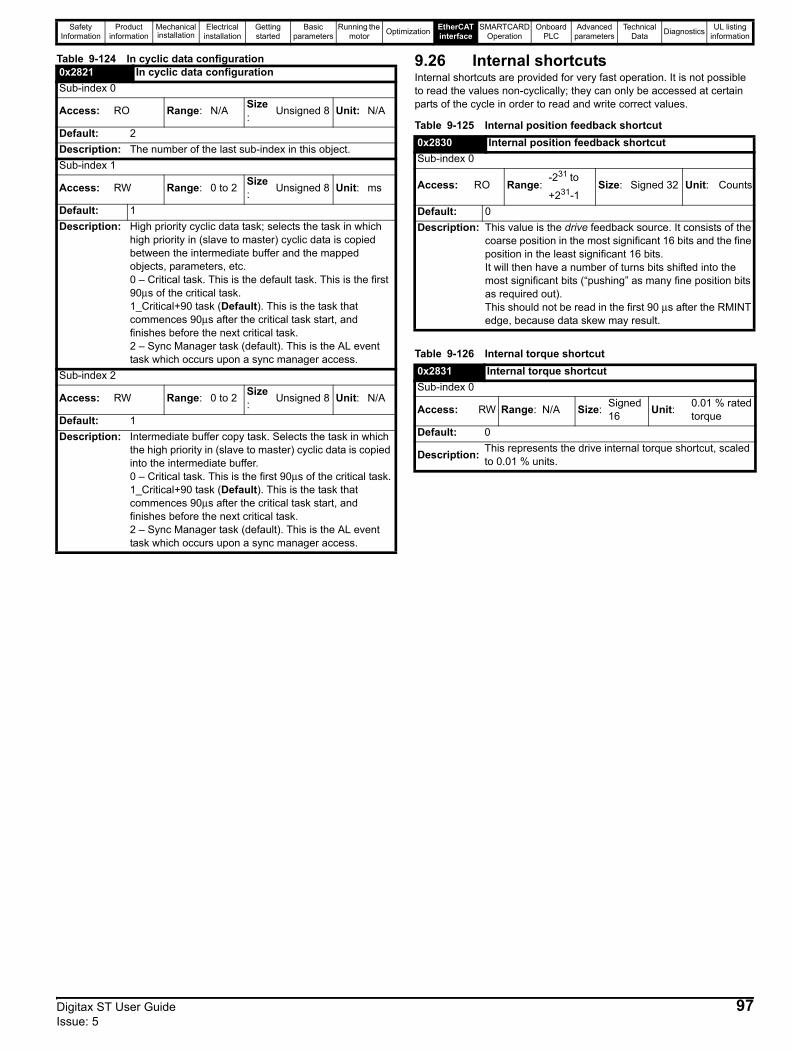
Safety Information
Product information
Mechanical installation
Electrical installation
Getting started
Basic parameters
Running the motor Optimization EtherCAT
interfaceSMARTCARD
OperationOnboard
PLCAdvanced
parametersTechnical
Data Diagnostics UL listing information
Table 9-124 In cyclic data configuration 9.26 Internal shortcutsInternal shortcuts are provided for very fast operation. It is not possible to read the values non-cyclically; they can only be accessed at certain parts of the cycle in order to read and write correct values.
Table 9-125 Internal position feedback shortcut
Table 9-126 Internal torque shortcut
0x2821 In cyclic data configurationSub-index 0
Access: RO Range: N/A Size: Unsigned 8 Unit: N/A
Default: 2Description: The number of the last sub-index in this object.Sub-index 1
Access: RW Range: 0 to 2 Size: Unsigned 8 Unit: ms
Default: 1Description: High priority cyclic data task; selects the task in which
high priority in (slave to master) cyclic data is copied between the intermediate buffer and the mapped objects, parameters, etc.0 – Critical task. This is the default task. This is the first 90μs of the critical task.1_Critical+90 task (Default). This is the task that commences 90μs after the critical task start, and finishes before the next critical task.2 – Sync Manager task (default). This is the AL event task which occurs upon a sync manager access.
Sub-index 2
Access: RW Range: 0 to 2 Size: Unsigned 8 Unit: N/A
Default: 1Description: Intermediate buffer copy task. Selects the task in which
the high priority in (slave to master) cyclic data is copied into the intermediate buffer.0 – Critical task. This is the first 90μs of the critical task.1_Critical+90 task (Default). This is the task that commences 90μs after the critical task start, and finishes before the next critical task.2 – Sync Manager task (default). This is the AL event task which occurs upon a sync manager access.
0x2830 Internal position feedback shortcutSub-index 0
Access: RO Range:-231
to
+231-1Size: Signed 32 Unit: Counts
Default: 0Description: This value is the drive feedback source. It consists of the
coarse position in the most significant 16 bits and the fine position in the least significant 16 bits. It will then have a number of turns bits shifted into the most significant bits (“pushing” as many fine position bits as required out).This should not be read in the first 90 μs after the RMINT edge, because data skew may result.
0x2831 Internal torque shortcutSub-index 0
Access: RW Range: N/A Size: Signed 16 Unit: 0.01 % rated
torqueDefault: 0
Description: This represents the drive internal torque shortcut, scaled to 0.01 % units.
Digitax ST User Guide 97Issue: 5
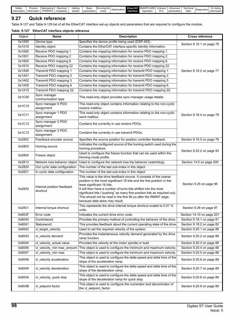
Safety Information
Product information
Mechanical installation
Electrical installation
Getting started
Basic parameters
Running the motor Optimization EtherCAT
interfaceSMARTCARD
OperationOnboard
PLCAdvanced
parametersTechnical
Data Diagnostics UL listing information
9.27 Quick referenceTable 9-127 and Table 9-129 list of all the EtherCAT interface set-up objects and parameters that are required to configure the module.
Table 9-127 EtherCAT interface objects reference
Object Name Description Cross reference0x1000 Device type Specifies the device profile being used (DSP-402).
Section 9.16.1 on page 760x1018 Identity object Contains the EtherCAT interface specific identity information.0x1600 Receive PDO mapping 1 Contains the mapping information for receive PDO mapping 1.
Section 9.16.2 on page 77
0x1601 Receive PDO mapping 2 Contains the mapping information for receive PDO mapping 2.0x1605 Receive PDO mapping 6 Contains the mapping information for receive PDO mapping 6.0x1615 Receive PDO mapping 22 Contains the mapping information for receive PDO mapping 22.0x1A00 Transmit PDO mapping 1 Contains the mapping information for transmit PDO mapping 1.0x1A01 Transmit PDO mapping 2 Contains the mapping information for transmit PDO mapping 2.0x1A02 Transmit PDO mapping 3 Contains the mapping information for transmit PDO mapping 3.0x1A05 Transmit PDO mapping 6 Contains the mapping information for transmit PDO mapping 6.0x1A15 Transmit PDO mapping 22 Contains the mapping information for transmit PDO mapping 22.
0x1C00 Sync manager communication type This read-only object provides sync manager usage details.
Section 9.16.4 on page 79
0x1C10 Sync manager 0 PDO assignment
This read-only object contains information relating to the non-cyclic receive mailbox.
0x1C11 Sync manager 1 PDO assignment
This read-only object contains information relating to the non-cyclic send mailbox.
0x1C12 Sync manager 2 PDO assignment Contains the currently in use receive PDOs.
0x1C13 Sync manager 3 PDO assignment Contains the currently in use transmit PDOs.
0x2802 Feedback encoder source Specifies the source position for position controller feedback. Section 9.16.5 on page 79
0x2803 Homing source Indicates the configured source of the homing switch used during the homing procedure.
Section 9.22.2 on page 930x2804 Freeze object Used to configure the freeze function that can be used within the
Homing mode profile.0x2813 Network loss behavior object Used to configure the network loss trip behavior (watchdog). Section 14.5 on page 2000x2820 Out cyclic data configuration The number of the last sub-index in this object
Section 9.25 on page 96
0x2821 In cyclic data configuration The number of the last sub-index in this object
0x2830 Internal position feedback shortcut
This value is the drive feedback source. It consists of the coarse position in the most significant 16 bits and the fine position in the least significant 16 bits. It will then have a number of turns bits shifted into the most significant bits (“pushing” as many fine position bits as required out). This should not be read in the first 90 μs after the RMINT edge, because data skew may result.
0x2831 Internal torque shortcut This represents the drive internal torque shortcut scaled to 0.01 % units. Section 9.26 on page 97
0x603F Error code Indicates the current drive error code. Section 14.10 on page 2010x6040 Controlword Provides the primary method of controlling the behavior of the drive. Section 9.18.1 on page 810x6041 Statusword This provides feedback about the current operating state of the drive. Section 9.18.2 on page 820x6042 vl_target_velocity Used to set the required velocity of the system. Section 9.20.1 on page 88
0x6043 vl_velocity demand Provides the instantaneous velocity demand generated by the drive ramp function. Section 9.20.2 on page 88
0x6044 vl_velocity_actual value Provides the velocity at the motor spindle or load. Section 9.20.3 on page 880x6046 vl_velocity_min max_amount This object is used to configure the minimum and maximum velocity. Section 9.20.4 on page 880x6047 vl_velocity_min max This object is used to configure the minimum and maximum velocity. Section 9.20.5 on page 88
0x6048 vl_velocity acceleration This object is used to configure the delta speed and delta time of the slope of the acceleration ramp. Section 9.20.6 on page 89
0x6049 vl_velocity deceleration This object is used to configure the delta speed and delta time of the slope of the deceleration ramp. Section 9.20.7 on page 89
0x604A vl_velocity_quick stop This object is used to configure the delta speed and delta time of the slope of the deceleration ramp for quick stop. Section 9.20.8 on page 89
0x604B vl_setpoint factor This object is used to configure the numerator and denominator of the vl_setpoint_factor. Section 9.20.9 on page 89
98 Digitax ST User Guide Issue: 5
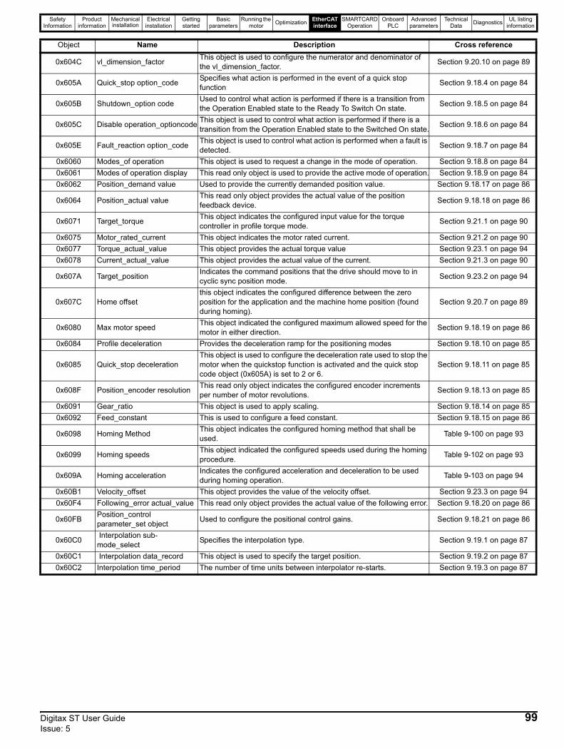
Safety Information
Product information
Mechanical installation
Electrical installation
Getting started
Basic parameters
Running the motor Optimization EtherCAT
interfaceSMARTCARD
OperationOnboard
PLCAdvanced
parametersTechnical
Data Diagnostics UL listing information
0x604C vl_dimension_factor This object is used to configure the numerator and denominator of the vl_dimension_factor. Section 9.20.10 on page 89
0x605A Quick_stop option_code Specifies what action is performed in the event of a quick stop function Section 9.18.4 on page 84
0x605B Shutdown_option code Used to control what action is performed if there is a transition from the Operation Enabled state to the Ready To Switch On state. Section 9.18.5 on page 84
0x605C Disable operation_optioncode This object is used to control what action is performed if there is a transition from the Operation Enabled state to the Switched On state. Section 9.18.6 on page 84
0x605E Fault_reaction option_code This object is used to control what action is performed when a fault is detected. Section 9.18.7 on page 84
0x6060 Modes_of operation This object is used to request a change in the mode of operation. Section 9.18.8 on page 840x6061 Modes of operation display This read only object is used to provide the active mode of operation. Section 9.18.9 on page 840x6062 Position_demand value Used to provide the currently demanded position value. Section 9.18.17 on page 86
0x6064 Position_actual value This read only object provides the actual value of the position feedback device. Section 9.18.18 on page 86
0x6071 Target_torque This object indicates the configured input value for the torque controller in profile torque mode. Section 9.21.1 on page 90
0x6075 Motor_rated_current This object indicates the motor rated current. Section 9.21.2 on page 900x6077 Torque_actual_value This object provides the actual torque value Section 9.23.1 on page 940x6078 Current_actual_value This object provides the actual value of the current. Section 9.21.3 on page 90
0x607A Target_position Indicates the command positions that the drive should move to in cyclic sync position mode. Section 9.23.2 on page 94
0x607C Home offsetthis object indicates the configured difference between the zero position for the application and the machine home position (found during homing).
Section 9.20.7 on page 89
0x6080 Max motor speed This object indicated the configured maximum allowed speed for the motor in either direction. Section 9.18.19 on page 86
0x6084 Profile deceleration Provides the deceleration ramp for the positioning modes Section 9.18.10 on page 85
0x6085 Quick_stop decelerationThis object is used to configure the deceleration rate used to stop the motor when the quickstop function is activated and the quick stop code object (0x605A) is set to 2 or 6.
Section 9.18.11 on page 85
0x608F Position_encoder resolution This read only object indicates the configured encoder increments per number of motor revolutions. Section 9.18.13 on page 85
0x6091 Gear_ratio This object is used to apply scaling. Section 9.18.14 on page 850x6092 Feed_constant This is used to configure a feed constant. Section 9.18.15 on page 86
0x6098 Homing Method This object indicates the configured homing method that shall be used. Table 9-100 on page 93
0x6099 Homing speeds This object indicated the configured speeds used during the homing procedure. Table 9-102 on page 93
0x609A Homing acceleration Indicates the configured acceleration and deceleration to be used during homing operation. Table 9-103 on page 94
0x60B1 Velocity_offset This object provides the value of the velocity offset. Section 9.23.3 on page 940x60F4 Following_error actual_value This read only object provides the actual value of the following error. Section 9.18.20 on page 86
0x60FB Position_control parameter_set object Used to configure the positional control gains. Section 9.18.21 on page 86
0x60C0 Interpolation sub-mode_select Specifies the interpolation type. Section 9.19.1 on page 87
0x60C1 Interpolation data_record This object is used to specify the target position. Section 9.19.2 on page 870x60C2 Interpolation time_period The number of time units between interpolator re-starts. Section 9.19.3 on page 87
Object Name Description Cross reference
Digitax ST User Guide 99Issue: 5
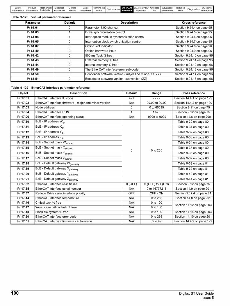
Safety Information
Product information
Mechanical installation
Electrical installation
Getting started
Basic parameters
Running the motor Optimization EtherCAT
interfaceSMARTCARD
OperationOnboard
PLCAdvanced
parametersTechnical
Data Diagnostics UL listing information
Table 9-128 Virtual parameter reference
Table 9-129 EtherCAT interface parameter reference
Parameter Default Description Cross referencePr 61.01 0 Parameter 1.00 shortcut Section 9.24.4 on page 95Pr 61.03 1 Drive synchronization control Section 9.24.5 on page 95Pr 61.04 1 Inter-option module synchronization control Section 9.24.6 on page 95Pr 61.05 0 Inter-option clock synchronization control Section 9.24.7 on page 95Pr 61.07 0 Option slot indicator Section 9.24.8 on page 96Pr 61.40 0 Option hardware issue Section 9.24.9 on page 96Pr 61.42 0 500 ms Task % free Section 9.24.10 on page 96Pr 61.43 0 External memory % free Section 9.24.11 on page 96Pr 61.44 0 Internal memory % free Section 9.24.12 on page 96Pr 61.49 0 The EtherCAT interface error sub-code Section 9.24.13 on page 96Pr 61.50 0 Bootloader software version - major and minor (XX.YY) Section 9.24.14 on page 96Pr 61.51 0 Bootloader software version -subversion (ZZ) Section 9.24.15 on page 96
Object Description Default Range Cross referencePr 17.01 EtherCAT interface ID code 421 - - - - Section 14.4.1 on page 199Pr 17.02 EtherCAT interface firmware - major and minor version N/A 00.00 to 99.99 Section 14.4.2 on page 199Pr 17.03 Node address 0 0 to 65535 Section 9.11 on page 75Pr 17.04 EtherCAT interface RUN 1 1 to 8 Section 9.12 on page 75Pr 17.06 EtherCAT interface operating status N/A -9999 to 9999 Section 14.6 on page 200Pr 17.10 EoE - IP address Wip
0 0 to 255
Table 9-30 on page 80
Pr 17.11 EoE - IP address Xip Table 9-31 on page 80
Pr 17.12 EoE - IP address Yip Table 9-32 on page 80
Pr 17.13 EoE - IP address Zip Table 9-33 on page 80
Pr 17.14 EoE - Subnet mask Wsubnet Table 9-34 on page 80
Pr 17.15 EoE - Subnet mask Xsubnet Table 9-35 on page 80
Pr 17.16 EoE - Subnet mask Ysubnet Table 9-36 on page 80
Pr 17.17 EoE - Subnet mask Zsubnet Table 9-37 on page 80
Pr 17.18 EoE - Default gateway Wgateway Table 9-38 on page 81
Pr 17.19 EoE - Default gateway Xgateway Table 9-39 on page 81
Pr 17.20 EoE - Default gateway Ygateway Table 9-40 on page 81
Pr 17.21 EoE - Default gateway Zgateway Table 9-41 on page 81Pr 17.32 EtherCAT interface re-initialize 0 (OFF) 0 (OFF) to 1 (ON) Section 9.12 on page 75Pr 17.35 EtherCAT interface serial number N/A 0 to 16777215 Section 14.9 on page 201Pr 17.37 Reduce Drive serial interface priority OFF OFF - ON Section 9.17.4 on page 81Pr 17.44 EtherCAT interface temperature N/A 0 to 255 Section 14.8 on page 201Pr 17.46 Critical task % free N/A 0 to 100
Section 14.12 on page 203Pr 17.47 Worst case critical task % free N/A 0 to 100Pr 17.48 Flash file system % free N/A 0 to 100 Section 14.14 on page 203Pr 17.50 EtherCAT interface error code N/A 0 to 255 Section 14.10 on page 201Pr 17.51 EtherCAT interface firmware - subversion N/A 0 to 99 Section 14.4.2 on page 199
100 Digitax ST User Guide Issue: 5

Safety Information
Product information
Mechanical installation
Electrical installation
Getting started
Basic parameters
Running the motor Optimization EtherCAT
interfaceSMARTCARD
OperationOnboard
PLCAdvanced
parametersTechnical
Data Diagnostics UL listing information
10 SMARTCARD Operation10.1 IntroductionThis is a standard feature that enables simple configuration of parameters in a variety of ways. The SMARTCARD can be used for: • Parameter copying between drives• Saving whole drive parameter sets• Saving ‘differences from default‘ parameter sets• Storing Onboard PLC programs• Automatically saving all user parameter changes for maintenance purposes• Loading complete motor map parametersThe SMARTCARD is located at the top of the module under the drive display (if installed) on the left-hand side. Ensure the SMARTCARD is inserted as shown on the SMARTCARD.The drive only communicates with the SMARTCARD when commanded to read or write, meaning the card may be "hot swapped".
Figure 10-1 Installation of the SMARTCARD
When inserting the SMARTCARD, always ensure that ST SP0 arrow points upwards.
Encoder phase angle The encoder phase angles in Pr 3.25 and Pr 21.20 are copied to the SMARTCARD when using any of the SMARTCARD transfer methods.
WARNING
Para
met
er -
Pr0.
30rE
Ad +
Auto
+
Prog
+
boot
+
NOTE
Be aware of possible live terminals when inserting the SMARTCARD.
WARNING
Digitax ST User Guide 101Issue: 5
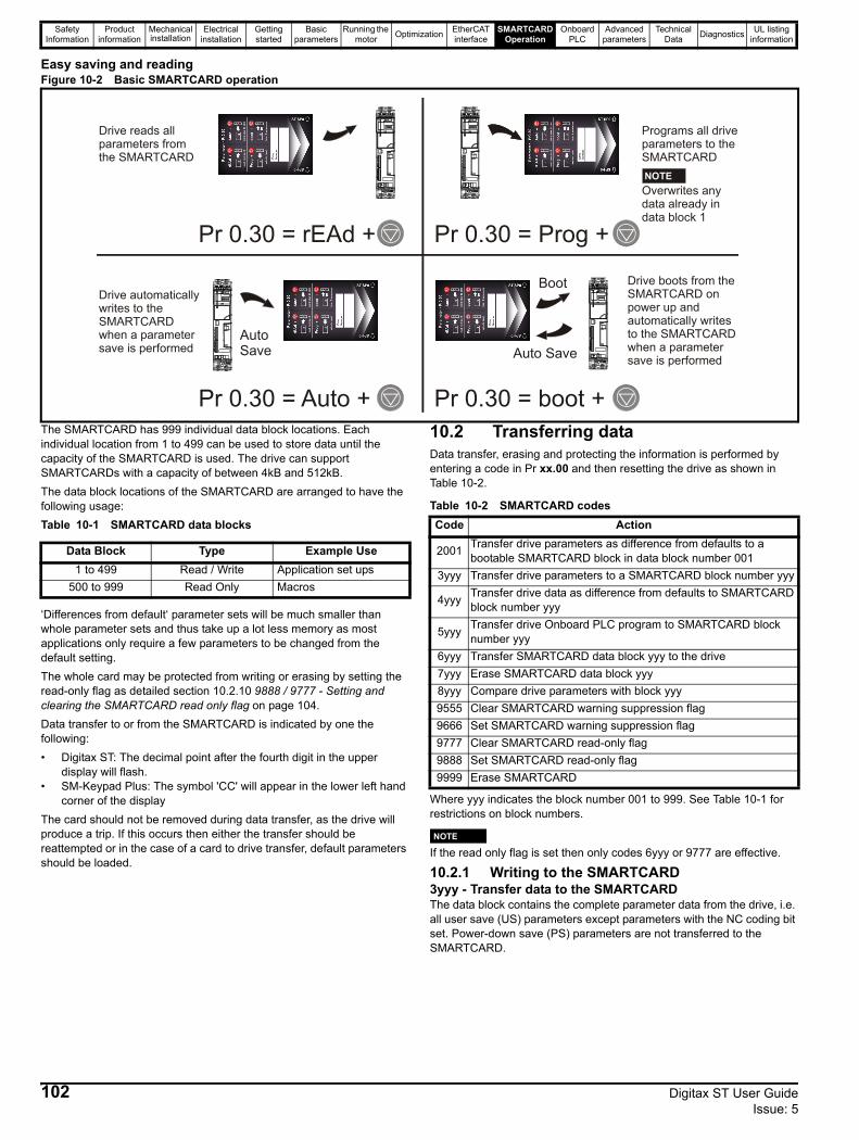
Safety Information
Product information
Mechanical installation
Electrical installation
Getting started
Basic parameters
Running the motor Optimization EtherCAT
interfaceSMARTCARD
OperationOnboard
PLCAdvanced
parametersTechnical
Data Diagnostics UL listing information
Easy saving and readingFigure 10-2 Basic SMARTCARD operation
The SMARTCARD has 999 individual data block locations. Each individual location from 1 to 499 can be used to store data until the capacity of the SMARTCARD is used. The drive can support SMARTCARDs with a capacity of between 4kB and 512kB. The data block locations of the SMARTCARD are arranged to have the following usage:Table 10-1 SMARTCARD data blocks
‘Differences from default‘ parameter sets will be much smaller than whole parameter sets and thus take up a lot less memory as most applications only require a few parameters to be changed from the default setting. The whole card may be protected from writing or erasing by setting the read-only flag as detailed section 10.2.10 9888 / 9777 - Setting and clearing the SMARTCARD read only flag on page 104. Data transfer to or from the SMARTCARD is indicated by one the following:• Digitax ST: The decimal point after the fourth digit in the upper
display will flash.• SM-Keypad Plus: The symbol 'CC' will appear in the lower left hand
corner of the displayThe card should not be removed during data transfer, as the drive will produce a trip. If this occurs then either the transfer should be reattempted or in the case of a card to drive transfer, default parameters should be loaded.
10.2 Transferring dataData transfer, erasing and protecting the information is performed by entering a code in Pr xx.00 and then resetting the drive as shown in Table 10-2.
Table 10-2 SMARTCARD codes
Where yyy indicates the block number 001 to 999. See Table 10-1 for restrictions on block numbers.
NIf the read only flag is set then only codes 6yyy or 9777 are effective.
10.2.1 Writing to the SMARTCARD3yyy - Transfer data to the SMARTCARDThe data block contains the complete parameter data from the drive, i.e. all user save (US) parameters except parameters with the NC coding bit set. Power-down save (PS) parameters are not transferred to the SMARTCARD.
Pr 0.30 = rEAd + Pr 0.30 = Prog +
Pr 0.30 = Auto + Pr 0.30 = boot +
AutoSave
Boot
Auto Save
Drive reads allparameters fromthe SMARTCARD
Drive automaticallywrites to theSMARTCARDwhen a parametersave is performed
Programs all driveparameters to theSMARTCARD
Drive boots from theSMARTCARD onpower up and automatically writes to the SMARTCARDwhen a parametersave is performed
NOTEOverwrites any data already in data block 1
Data Block Type Example Use1 to 499 Read / Write Application set ups
500 to 999 Read Only Macros
Code Action
2001 Transfer drive parameters as difference from defaults to a bootable SMARTCARD block in data block number 001
3yyy Transfer drive parameters to a SMARTCARD block number yyy
4yyy Transfer drive data as difference from defaults to SMARTCARD block number yyy
5yyy Transfer drive Onboard PLC program to SMARTCARD block number yyy
6yyy Transfer SMARTCARD data block yyy to the drive7yyy Erase SMARTCARD data block yyy8yyy Compare drive parameters with block yyy9555 Clear SMARTCARD warning suppression flag 9666 Set SMARTCARD warning suppression flag 9777 Clear SMARTCARD read-only flag9888 Set SMARTCARD read-only flag9999 Erase SMARTCARD
NOTE
102 Digitax ST User Guide Issue: 5
Safety Information
Product information
Mechanical installation
Electrical installation
Getting started
Basic parameters
Running the motor Optimization EtherCAT
interfaceSMARTCARD
OperationOnboard
PLCAdvanced
parametersTechnical
Data Diagnostics UL listing information
4yyy - Write default differences to a SMARTCARDThe data block only contains the parameter differences from the last time default settings were loaded.Six bytes are required for each parameter difference. The data density is not as high as when using the 3yyy transfer method as described in the previous section, but in most cases the number of differences from default is small and the data blocks are therefore smaller. This method can be used for creating drive macros. Power-down save (PS) parameters are not transferred to the SMARTCARD.All user save (US) parameters including those that do not have a default value (i.e. Pr 3.25 or Pr 21.20 Encoder phase angle), but not including those with the NC (Not copied) coding bit set can be transferred to the SMARTCARD. In addition to these parameters all menu 20 parameters (except Pr 20.00), can be transferred to the SMARTCARD even though they are not user save parameters and have the NC coding bit set.It is possible to transfer parameters between drives with each of the different formats, however, the data block compare function does not work with data produced by different formats.
Writing a parameter set to the SMARTCARD (Pr 11.42 = Prog (2))Setting Pr 11.42 to Prog (2) and resetting the drive will save the parameters to the SMARTCARD, i.e. this is equivalent to writing 3001 to Pr xx.00. All SMARTCARD trips apply except 'C.Chg'. If the data block already exists it is automatically overwritten. When the action is complete this parameter is automatically reset to nonE (0).
10.2.2 Reading from the SMARTCARD6yyy - Read default differences from a SMARTCARDWhen the data is transferred back to a drive, using 6yyy in Pr xx.00, it is transferred to the drive RAM and the drive EEPROM. A parameter save is not required to retain the data after power-down. Set up data for any Solutions Modules installed are stored on the card and are transferred to the destination drive. If the Solutions Modules are different between the source and destination drive, the menus for the slots where the Solutions Module categories are different are not updated from the card and will contain their default values after the copying action. The drive will produce a 'C.Optn' trip if the Solutions Modules installed to the source and destination drive are different or are in different slots. If the data is being transferred to a drive of a different voltage or current rating a 'C.rtg' trip will occur. The following drive rating dependant parameters (RA coding bit set) will not be transferred to the destination drive by a SMARTCARD when the rating of the destination drive is different from the source drive and the file is a parameter file (i.e. created using the 3yyy transfer method). However drive rating dependent parameters will be transferred if only the current rating is different and the file is a differences from default type file (i.e. created using the 4yyy transfer method). If drive rating dependant parameters are not transferred to the destination drive they will contain their default values.
Pr 2.08 Standard ramp voltagePr 4.05 to Pr 4.07 and Pr 21.27 to Pr 21.29 Current limitsPr 4.24, User current maximum scalingPr 5.07, Pr 21.07 Motor rated currentPr 5.09, Pr 21.09 Motor rated voltagePr 5.10, Pr 21.10 Rated power factorPr 5.17, Pr 21.12 Stator resistancePr 5.18 Switching frequencyPr 5.23, Pr 21.13 Voltage offsetPr 5.24, Pr 21.14 Transient inductancePr 5.25, Pr 21.24 Stator inductancePr 6.06 DC injection braking currentPr 6.48 Line power supply loss ride through detection level
Reading a parameter set from the SMARTCARD (Pr 11.42 = rEAd (1)) Setting Pr 11.42 to rEAd (1) and resetting the drive will transfer the parameters from the card into the drive parameter set and the drive EEPROM, i.e. this is equivalent to writing 6001 to Pr xx.00. All SMARTCARD trips apply. Once the parameters are successfully copied
this parameter is automatically reset to nonE (0). Parameters are saved to the drive EEPROM after this action is complete.
NThis operation is only performed if data block 1 on the card is a full parameter set (3yyy transfer) and not a default difference file (4yyy transfer). If block 1 does not exist a 'C.dAt' trip occurs.
10.2.3 Auto saving parameter changes (Pr 11.42 = Auto (3))
This setting causes the drive to automatically save any changes made to menu 0 parameters on the drive to the SMARTCARD. The latest menu 0 parameter set in the drive is therefore always backed up on the SMARTCARD. Changing Pr 11.42 to Auto (3) and resetting the drive will immediately save the complete parameter set from the drive to the card, i.e. all user save (US) parameters except parameters with the NC coding bit set. Once the whole parameter set is stored only the individual modified menu 0 parameter setting is updated.Advanced parameter changes are only saved to the card when Pr xx.00 is set to a 1000 and the drive reset.All SMARTCARD trips apply, except ‘C.Chg’. If the data block already contains information it is automatically overwritten. If the card is removed when Pr 11.42 is set to 3 Pr 11.42 is then automatically set to nonE (0). When a new SMARTCARD is installed Pr 11.42 must be set back to Auto (3) by the user and the drive reset so the complete parameter set is rewritten to the new SMARTCARD if auto mode is still required. When Pr 11.42 is set to Auto (3) and the parameters in the drive are saved, the SMARTCARD is also updated, therefore the SMARTCARD becomes a copy of the drives stored configuration. At power up, if Pr 11.42 is set to Auto (3), the drive will save the complete parameter set to the SMARTCARD. The drive will display ‘cArd’ during this operation. This is done to ensure that if a user puts a new SMARTCARD in during power down the new SMARTCARD will have the correct data.
NWhen Pr 11.42 is set to Auto (3) the setting of Pr 11.42 itself is saved to the drive EEPROM but NOT to the SMARTCARD.
10.2.4 Booting up from the SMARTCARD on every power up (Pr 11.42 = boot (4))
When Pr 11.42 is set to boot (4) the drive operates the same as Auto mode except when the drive is powered-up. The parameters on the SMARTCARD will be automatically transferred to the drive at power up if the following are true:• A card is inserted in the drive• Parameter data block 1 exists on the card• The data in block 1 is type 1 to 5 (as defined in Pr 11.38)• Pr 11.42 on the card set to boot (4)The drive will display 'boot' during this operation. If the drive mode is different from that on the card, the drive gives a 'C.Typ'. trip and the data is not transferred. If 'boot' mode is stored on the copying SMARTCARD this makes the copying SMARTCARD the master device. This provides a very fast and efficient way of re-programming a number of drives.If data block 1 contains a bootable parameter set and data block 2 contains an Onboard PLC program (type 17 as defined in Pr 11.38), then the onboard PLC program will be transferred to the drive at power up along with the parameter set in data block 1.
N‘Boot’ mode is saved to the card, but when the card is read, the value of Pr 11.42 is not transferred to the drive.
10.2.5 Booting up from the SMARTCARD on every power up (Pr xx.00 = 2001)
It is possible to create a difference from default bootable file by setting Pr xx.00 to 2001 and resetting the drive. This type of file causes the drive to behave in the same way at power-up as a file created with boot
NOTE
NOTE
NOTE
Digitax ST User Guide 103Issue: 5
Safety Information
Product information
Mechanical installation
Electrical installation
Getting started
Basic parameters
Running the motor Optimization EtherCAT
interfaceSMARTCARD
OperationOnboard
PLCAdvanced
parametersTechnical
Data Diagnostics UL listing information
mode set up with Pr 11.42. The difference from the default file is that it has the added advantage of including menu 20 parameters. Setting Pr xx.00 to 2001 will overwrite data block 1 on the card if it already exists.If a data block 2 exists and contains an Onboard PLC program (type 17 as defined in Pr 11.38), this will also be loaded after the parameters have been transferredA bootable difference from default file can only be created in one operation and parameters cannot be added as they are saved via menu 0.
10.2.6 8yyy - Comparing the drive full parameter set with the SMARTCARD values
Setting 8yyy in Pr xx.00, will compare the SMARTCARD file with the data in the drive. If the compare is successful Pr xx.00 is simply set to 0. If the compare fails a ‘C.cpr’ trip is initiated.
10.2.7 7yyy / 9999 - Erasing data from the SMARTCARD
Data can be erased from the SMARTCARD either one block at a time or all blocks in one go. • Setting 7yyy in Pr xx.00 will erase SMARTCARD data block yyy. • Setting 9999 in Pr xx.00 will erase all SMARTCARD data blocks
10.2.8 SM-Applications Modules And Motion Processors program to/from SMARTCARD transfer system
The following additional codes can be used in Pr x.00 and will initiate the specified actions when a drive reset occurs.
If the action is not possible because there is no applications category module in the requested slot then Pr x.00 remains at the value set by the user. If the action is not possible for any other reason a C.SLx trip is produced where x is the slot number. The possible reasons are:1. The data block to be read from the card does not exist or the data
block is of the wrong type.2. Either the data block to be written to the card already exists or the
program in the module is identical to that on the SMARTCARD.3. A failure has occurred within the Solutions Module and it has
stopped the transfer process.4. The data block to be written to the card is not copyable. To resolve
this, allow copying within CTSoft or SyPTPro.5. The SMARTCARD does not have enough free memory. To resolve
use an empty SMARTCARD or a high capacity SMARTCARD (64KB).
10.2.9 9666 / 9555 - Setting and clearing the SMARTCARD warning suppression flag
If the Solutions Modules installed to the source and destination drive are different or are in different slots the drive will produce a 'C.Optn' trip. If the data is being transferred to a drive of a different voltage or current rating a 'C.rtg' trip will occur. It is possible to suppress these trips by setting the warning suppression flag. If this flag is set the drive will not trip if the Solutions Module(s) or drive ratings are different between the
source and destination drives. The Solutions Module or rating dependent parameters will not be transferred.• Setting 9666 in Pr xx.00 will set the warning suppression flag• Setting 9555 in Pr xx.00 will clear the warning suppression flag
10.2.10 9888 / 9777 - Setting and clearing the SMARTCARD read only flag
The SMARTCARD may be protected from writing or erasing by setting the read only flag. If an attempt is made to write or erase a data block when the read only flag is set, a 'C.Rdo' trip is initiated. When the read only flag is set only codes 6yyy or 9777 are effective.• Setting 9888 in Pr xx.00 will set the read only flag• Setting 9777 in Pr xx.00 will clear the read only flag.
10.3 Data block header informationEach data block stored on a SMARTCARD has header information detailing the following:• A number which identifies the block (Pr 11.37)• The type of data stored in the block (Pr 11.38)• The drive mode if the data is parameter data (Pr 11.38)• The version number (Pr 11.39)• The checksum (Pr 11.40)• The read-only flag• The warning suppression flag The header information for each data block which has been used can be viewed in Pr 11.38 to Pr 11.40 by increasing or decreasing the data block number set in Pr 11.37. If Pr 11.37 is set to 1000 the checksum parameter (Pr 11.40) shows the number of 16 byte pages left on the card.If Pr 11.37 is set to 1001 the checksum parameter (Pr 11.40) shows the total capacity of the card in 16 byte pages. Therefore, for a 4 kB card this parameter would show 254.If Pr 11.37 is set to 1002 the checksum parameter (Pr 11.40) shows the state of the read-only (bit 0) and warning suppression flags (bit 1). Software version xx.xx.xx: If Pr 11.37 is set to 1003, the checksum parameter (Pr 11.40) shows the product identifier (2 = Digitax ST).If there is no data on the card Pr 11.37 can only have values of 0 or 1000 to 1003.
10.4 SMARTCARD parametersTable 10-3 Key to parameter table coding
This parameter shows the number of the data block last transferred from a SMARTCARD to the drive.
This parameter should have the data block number entered for which the user would like information displayed in Pr 11.38, Pr 11.39 and Pr 11.40.
Value Action
15yyy Transfer the user program in the applications module in slot 1 to data block number yyy on a SMARTCARD
16yyy Transfer the user program in the applications module in slot 2 to data block number yyy on a SMARTCARD
17yyyTransfer the user program in the SM-Applications Modules And Motion Processors (Digitax ST Plus and Indexer) to data block number yyy on a SMARTCARD
18yyy Transfer a user program in data block number yyy on a SMARTCARD to the applications module in slot 1
19yyy Transfer a user program in data block number yyy on a SMARTCARD to the applications module in slot 2
20yyyTransfer a user program in data block number yyy on a SMARTCARD to the SM-Applications Modules And Motion Processors (Digitax ST Plus and Indexer)
RW Read / Write RO Read only Uni UnipolarBi Bi-polar Bit Bit parameter Txt Text stringFI Filtered DE Destination NC Not copiedRA Rating dependent PT Protected US User savePS Power down save
11.36 {0.29} SMARTCARD parameter data previously loadedRO Uni NC PT US
0 to 999 0
11.37 SMARTCARD data numberRW Uni NC
0 to 1003 0
104 Digitax ST User Guide Issue: 5
Safety Information
Product information
Mechanical installation
Electrical installation
Getting started
Basic parameters
Running the motor Optimization EtherCAT
interfaceSMARTCARD
OperationOnboard
PLCAdvanced
parametersTechnical
Data Diagnostics UL listing information
Gives the type/mode of the data block selected with Pr 11.37
Gives the version number of the data block selected in Pr 11.37.
Gives the checksum of the data block selected in Pr 11.37.
NIf Pr 11.42 is equal to 1 or 2, this value is not transferred to the drive or saved to the EEPROM. If Pr 11.42 is set to a 3 or 4 the value is transferred.
nonE (0) = InactiverEAd (1) = Read parameter set from the SMARTCARD Prog (2) = Programming a parameter set to the SMARTCARDAuto (3) = Auto saveboot (4) = Boot mode
11.38 SMARTCARD data type/modeRO Txt NC PT
0 to 18
Pr 11.38 String Type/mode Data stored
0 FrEE Value when Pr 11.37 = 0, 1000 to 1003
1 Reserved
2 3OpEn.LP Open-loop mode parameters Data from EEPROM
6 to 8 3Un Unused9 Reserved
10 4OpEn.LP Open-loop mode parametersDefaults last loaded and differences
11 4CL.VECt Closed-loop vector mode parameters14 to 16 4Un Unused
17 LAddEr Onboard PLC program18 Option A Solutions Module file
19 Opt.Prg Solutions Module program data block present
11.39 SMARTCARD data versionRW Uni NC
0 to 9,999 0
11.40 SMARTCARD data checksumR0 Uni NC PT
0 to 65,335
11.42 {0.30} Parameter copyingRW Txt NC US*
0 to 4 nonE (0)
NOTE
Digitax ST User Guide 105Issue: 5
Safety Information
Product information
Mechanical installation
Electrical installation
Getting started
Basic parameters
Running the motor Optimization EtherCAT
interfaceSMARTCARD
OperationOnboard
PLCAdvanced
parametersTechnical
Data Diagnostics UL listing information
10.5 SMARTCARD tripsAfter an attempt to read, write or erase data to or from a SMARTCARD a trip may occur if there has been a problem with the command. The following trips indicate various problems as detailed in Table 10-4.
Table 10-4 Trip conditionsTrip Diagnosis
C.Acc SMARTCARD trip: SMARTCARD Read / Write fail
185Check SMARTCARD is installed / located correctlyEnsure SMARTCARD is not writing data to data location 500 to 999Replace SMARTCARD
C.boot SMARTCARD trip: The menu 0 parameter modification cannot be saved to the SMARTCARD because the necessary file has not been created on the SMARTCARD
177
A write to a menu 0 parameter has been initiated via the keypad with Pr 11.42 set to auto(3) or boot(4), but the necessary file on the SMARTCARD has not been createdEnsure that Pr 11.42 is correctly set and reset the drive to create the necessary file on the SMARTCARDRe-attempt the parameter write to the menu 0 parameter
C.bUSY SMARTCARD trip: SMARTCARD can not perform the required function as it is being accessed by a Solutions Module178 Wait for the Solutions Module to finish accessing the SMARTCARD and then re-attempt the required function
C.Chg SMARTCARD trip: Data location already contains data
179 Erase data in data locationWrite data to an alternative data location
C.Cpr SMARTCARD trip: The values stored in the drive and the values in the data block on the SMARTCARD are different188 Press the red reset button
C.dat SMARTCARD trip: Data location specified does not contain any data183 Ensure data block number is correct
C.Err SMARTCARD trip: SMARTCARD data is corrupted
182Ensure the card is located correctlyErase data and retryReplace SMARTCARD
C.Full SMARTCARD trip: SMARTCARD full184 Delete a data block or use a different SMARTCARD
C.Optn SMARTCARD trip: Solutions Modules installed are different between source drive and destination drive
180Ensure correct Solutions Modules are installed Ensure Solutions Modules are in the same Solutions Module slotPress the red reset button
C.Prod SMARTCARD trip: The data blocks on the SMARTCARD are not compatible with this product
175 Erase all data on the SMARTCARD by setting Pr xx.00 to 9999 and pressing the red reset buttonReplace SMARTCARD
C.Rdo SMARTCARD trip: SMARTCARD has the Read only bit set
181 Enter 9777 in Pr xx.00 to allow SMARTCARD Read / Write access Ensure card is not writing to data locations 500 to 999
C.SLX An error has occurred when attempting to transfer a user program from a Solutions Module to a SMARTCARD and vice versa
172,173,174 See section 10.2.8 SM-Applications Modules And Motion Processors program to/from SMARTCARD transfer system on page 104 for more information.
106 Digitax ST User Guide Issue: 5
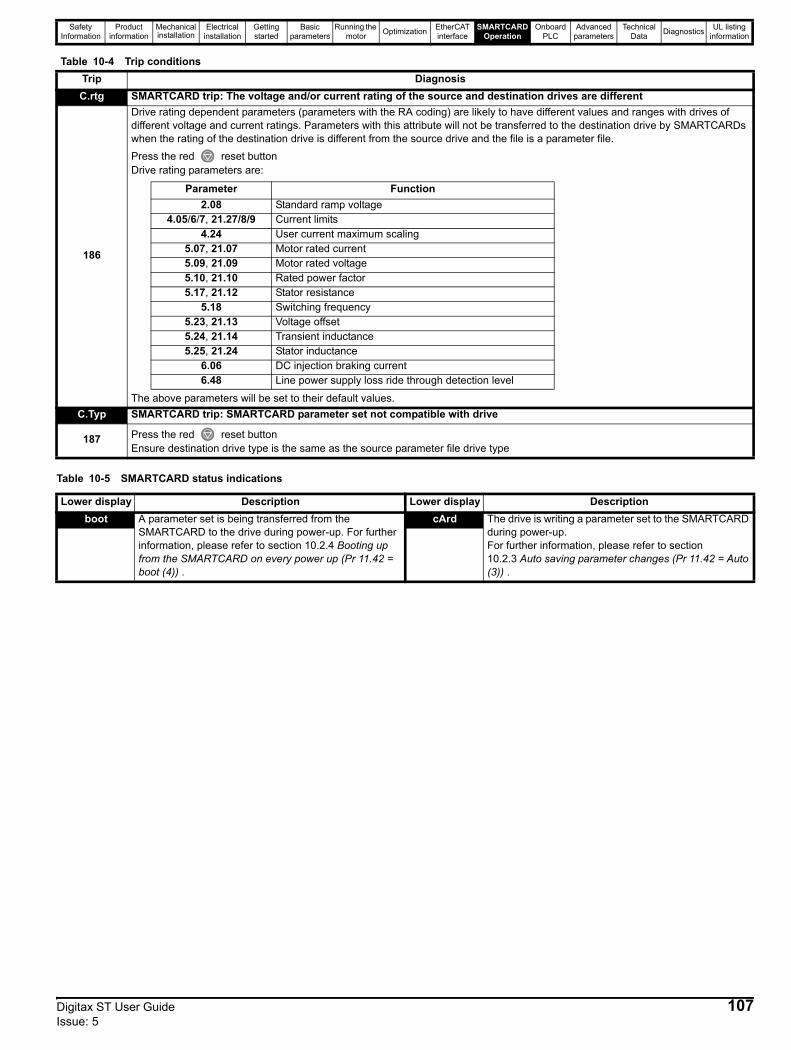
Safety Information
Product information
Mechanical installation
Electrical installation
Getting started
Basic parameters
Running the motor Optimization EtherCAT
interfaceSMARTCARD
OperationOnboard
PLCAdvanced
parametersTechnical
Data Diagnostics UL listing information
Table 10-5 SMARTCARD status indications
C.rtg SMARTCARD trip: The voltage and/or current rating of the source and destination drives are different
186
Drive rating dependent parameters (parameters with the RA coding) are likely to have different values and ranges with drives of different voltage and current ratings. Parameters with this attribute will not be transferred to the destination drive by SMARTCARDs when the rating of the destination drive is different from the source drive and the file is a parameter file. Press the red reset buttonDrive rating parameters are:
The above parameters will be set to their default values.C.Typ SMARTCARD trip: SMARTCARD parameter set not compatible with drive
187 Press the red reset buttonEnsure destination drive type is the same as the source parameter file drive type
Table 10-4 Trip conditionsTrip Diagnosis
Parameter Function2.08 Standard ramp voltage
4.05/6/7, 21.27/8/9 Current limits4.24 User current maximum scaling
5.07, 21.07 Motor rated current5.09, 21.09 Motor rated voltage5.10, 21.10 Rated power factor5.17, 21.12 Stator resistance
5.18 Switching frequency5.23, 21.13 Voltage offset5.24, 21.14 Transient inductance5.25, 21.24 Stator inductance
6.06 DC injection braking current6.48 Line power supply loss ride through detection level
Lower display Description Lower display Descriptionboot A parameter set is being transferred from the
SMARTCARD to the drive during power-up. For further information, please refer to section 10.2.4 Booting up from the SMARTCARD on every power up (Pr 11.42 = boot (4)) .
cArd The drive is writing a parameter set to the SMARTCARD during power-up.For further information, please refer to section 10.2.3 Auto saving parameter changes (Pr 11.42 = Auto (3)) .
Digitax ST User Guide 107Issue: 5

Safety Information
Product information
Mechanical installation
Electrical installation
Getting started
Basic parameters
Running the motor Optimization EtherCAT
interfaceSMARTCARD
OperationOnboard
PLCAdvanced
parametersTechnical
Data Diagnostics UL listing information
11 Onboard PLC11.1 Onboard PLC and SYPTLiteThe Digitax ST has the ability to store and execute a 4KB Onboard PLC ladder logic program without the need for additional hardware.The ladder logic program is written using SYPTLite, a Windows™ based ladder diagram editor allowing the development of programs for execution in Digitax ST.SYPTLite is designed to be easy to use and to make program development as simple as possible. The features provided are a sub-set of those in the SYPT program editor. SYPTLite programs are developed using ladder logic, a graphical language widely used to program PLCs (IEC61131-3). SYPTLite allows the user to "draw" a ladder diagram representing a program. SYPTLite provides a complete environment for the development of ladder diagrams. Ladder diagrams can be created, compiled into user programs and downloaded to a Digitax ST for execution, via the RJ45 serial communications port on the front of the drive. The run-time operation of the compiled ladder diagram on the target can also be monitored using SYPTLite and facilities are provided to interact with the program on the target by setting new values for target parameters.
11.2 BenefitsThe combination of the Onboard PLC and SYPTLite, means that Digitax ST can replace nano and some micro PLCs in many applications. The Onboard PLC programs can consist of up to a maximum of 50 ladder logic rungs (up to 7 function blocks and 10 contacts per rung). The Onboard PLC program can also be transferred to and from a SMARTCARD for backup or quick commissioning / start-up In addition to the basic ladder symbols, SYPTLite contains a sub-set of the function from the full version of SYPT. These include,• Arithmetic blocks• Comparison blocks• Timers• Counters• Multiplexers• Latches• Bit manipulationTypical applications for the Onboard PLC include,• Interlocking logic• Sequences routines• Custom control words.
11.3 LimitationsThe Onboard PLC program has the following limitations:• The maximum program size is 4032 bytes including header and
optional source code.• The Digitax ST is rated for 100 program downloads. This limitation is
imposed by the flash memory used to store the program within the drive.
• The user cannot create user variables. The user is only able to manipulate the drive parameter set.
• The program cannot be downloaded or monitored over CTNet. The program is only accessible via the drives RJ45 serial communications port.
• There are no real-time tasks, i.e. the scheduling rate of the program cannot be guaranteed. SM-Applications tasks such as Clock, Event, Pos0 or Speed are not available. The Onboard PLC should not be used for time-critical applications.
• The program runs at a low priority. The Digitax ST provides a single background task in which to run a ladder diagram. The drive is prioritized to perform its major functions first, e.g. motor control, and will use any remaining processing time to execute the ladder diagram as a background activity. As the drive's processor becomes more heavily loaded, less time is spent executing the program.
Figure 11-1 Digitax ST Onboard PLC program scheduling
The user program is scheduled for a short period approximately once every 64 ms. The time for which the program is scheduled will vary between 0.2 ms and 2 ms depending on the loading of the drive's processor.When scheduled, several scans of the user program may be performed. Some scans may execute in microseconds. However, when the main drive functions are scheduled there will be a pause in the execution of the program causing some scans to take many milliseconds. SYPTLite displays the average execution time calculated over the last 10 scans of the user program.
11.4 Getting startedSYPTLite can be downloaded at: http://www.emersonindustrial.com/en-EN/controltechniques/products/software/programming/syptlite/Pages/default.aspx.SYPTLite system requirements• Windows 2000/XP/Vista. Windows 95/98/98SE/Me/NT4 are not
supported• Pentium III 500 MHz or better recommended• 128 MB RAM • Minimum of 800x600 shield resolution. 1024x768 is recommended • Adobe Acrobat 5.10 or later (for viewing User Guides) • Microsoft Internet Explorer V5.0 or later • RS232 to RS485, RJ45 communications lead to connect the PC to a
Digitax ST• Administrator rights under Windows NT/2000/XP/Vista are required
to install the softwareSee the SYPTLite help file for more information regarding using SYPTLite, creating ladder diagrams and the available function blocks.
11.5 Onboard PLC parametersThe following parameters are associated with the Onboard PLC program.
This parameter is used to start and stop the drive Onboard PLC program.
11.47 Drive Onboard PLC program enableRW Uni US
0 to 2 2
Value Description0 Halt the drive Onboard PLC program.
1
Run the drive Onboard PLC program (if installed). Any out-of-range parameter writes attempted will be clipped to the maximum / minimum values valid for that parameter before being written.
2 Run the drive Onboard PLC program (if installed). Any out-of-range parameter writes attempted will cause a ‘UP ovr’ trip.
Major drivefunctions
Userprogram
0 64 128Time
(milliseconds)
108 Digitax ST User Guide Issue: 5
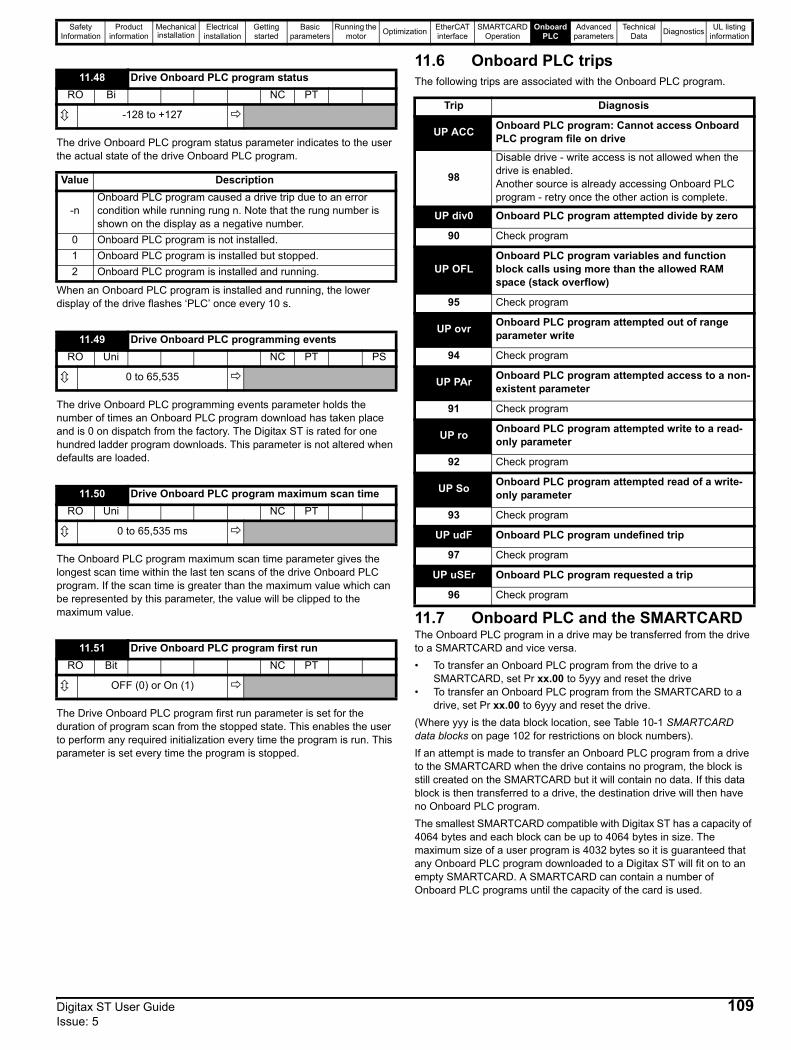
Safety Information
Product information
Mechanical installation
Electrical installation
Getting started
Basic parameters
Running the motor Optimization EtherCAT
interfaceSMARTCARD
OperationOnboard
PLCAdvanced
parametersTechnical
Data Diagnostics UL listing information
The drive Onboard PLC program status parameter indicates to the user the actual state of the drive Onboard PLC program.
When an Onboard PLC program is installed and running, the lower display of the drive flashes ‘PLC’ once every 10 s.
The drive Onboard PLC programming events parameter holds the number of times an Onboard PLC program download has taken place and is 0 on dispatch from the factory. The Digitax ST is rated for one hundred ladder program downloads. This parameter is not altered when defaults are loaded.
The Onboard PLC program maximum scan time parameter gives the longest scan time within the last ten scans of the drive Onboard PLC program. If the scan time is greater than the maximum value which can be represented by this parameter, the value will be clipped to the maximum value.
The Drive Onboard PLC program first run parameter is set for the duration of program scan from the stopped state. This enables the user to perform any required initialization every time the program is run. This parameter is set every time the program is stopped.
11.6 Onboard PLC tripsThe following trips are associated with the Onboard PLC program.
11.7 Onboard PLC and the SMARTCARDThe Onboard PLC program in a drive may be transferred from the drive to a SMARTCARD and vice versa.• To transfer an Onboard PLC program from the drive to a
SMARTCARD, set Pr xx.00 to 5yyy and reset the drive• To transfer an Onboard PLC program from the SMARTCARD to a
drive, set Pr xx.00 to 6yyy and reset the drive.(Where yyy is the data block location, see Table 10-1 SMARTCARD data blocks on page 102 for restrictions on block numbers).If an attempt is made to transfer an Onboard PLC program from a drive to the SMARTCARD when the drive contains no program, the block is still created on the SMARTCARD but it will contain no data. If this data block is then transferred to a drive, the destination drive will then have no Onboard PLC program. The smallest SMARTCARD compatible with Digitax ST has a capacity of 4064 bytes and each block can be up to 4064 bytes in size. The maximum size of a user program is 4032 bytes so it is guaranteed that any Onboard PLC program downloaded to a Digitax ST will fit on to an empty SMARTCARD. A SMARTCARD can contain a number of Onboard PLC programs until the capacity of the card is used.
11.48 Drive Onboard PLC program statusRO Bi NC PT
-128 to +127
Value Description
-nOnboard PLC program caused a drive trip due to an error condition while running rung n. Note that the rung number is shown on the display as a negative number.
0 Onboard PLC program is not installed.1 Onboard PLC program is installed but stopped.2 Onboard PLC program is installed and running.
11.49 Drive Onboard PLC programming eventsRO Uni NC PT PS
0 to 65,535
11.50 Drive Onboard PLC program maximum scan timeRO Uni NC PT
0 to 65,535 ms
11.51 Drive Onboard PLC program first runRO Bit NC PT
OFF (0) or On (1)
Trip Diagnosis
UP ACC Onboard PLC program: Cannot access Onboard PLC program file on drive
98
Disable drive - write access is not allowed when the drive is enabled.Another source is already accessing Onboard PLC program - retry once the other action is complete.
UP div0 Onboard PLC program attempted divide by zero
90 Check program
UP OFLOnboard PLC program variables and function block calls using more than the allowed RAM space (stack overflow)
95 Check program
UP ovr Onboard PLC program attempted out of range parameter write
94 Check program
UP PAr Onboard PLC program attempted access to a non-existent parameter
91 Check program
UP ro Onboard PLC program attempted write to a read-only parameter
92 Check program
UP So Onboard PLC program attempted read of a write-only parameter
93 Check program
UP udF Onboard PLC program undefined trip
97 Check program
UP uSEr Onboard PLC program requested a trip
96 Check program
Digitax ST User Guide 109Issue: 5
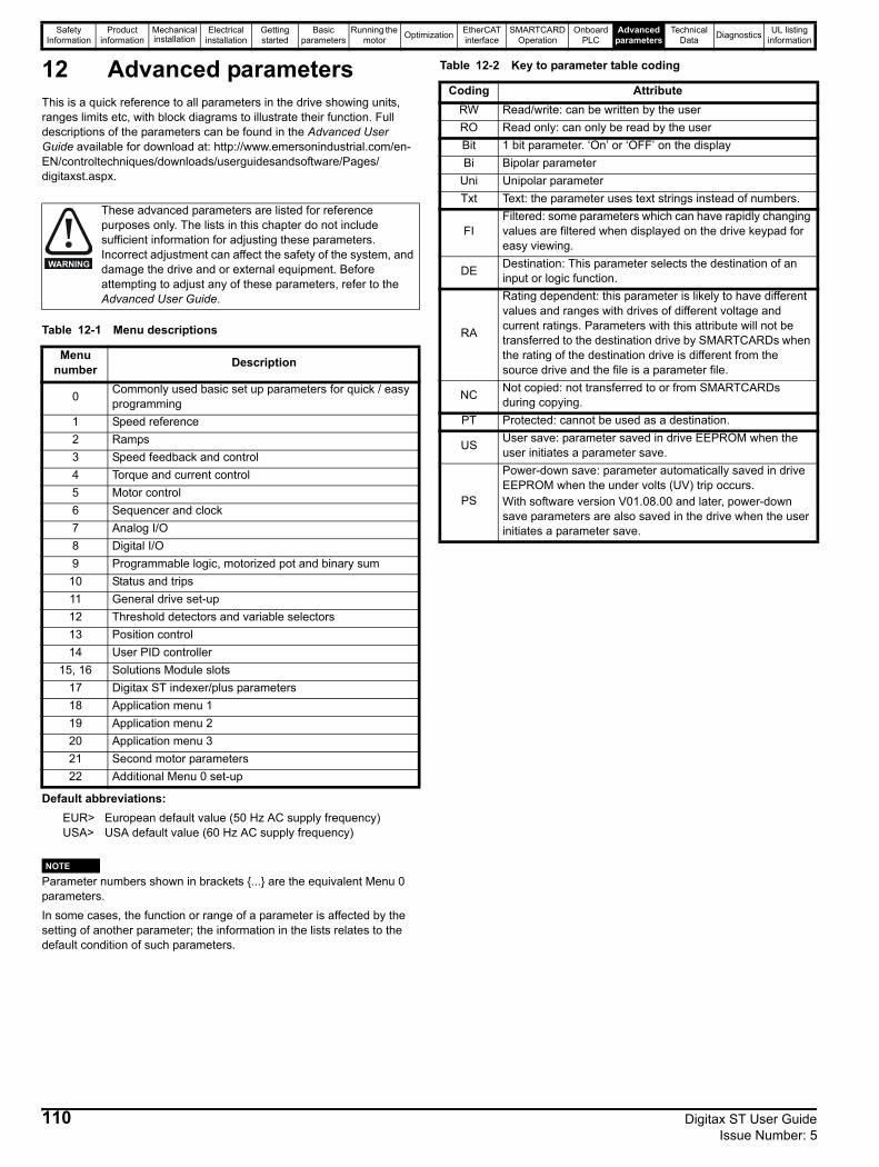
Safety Information
Product information
Mechanical installation
Electrical installation
Getting started
Basic parameters
Running the motor Optimization EtherCAT
interfaceSMARTCARD
OperationOnboard
PLCAdvanced
parametersTechnical
Data Diagnostics UL listing information
12 Advanced parametersThis is a quick reference to all parameters in the drive showing units, ranges limits etc, with block diagrams to illustrate their function. Full descriptions of the parameters can be found in the Advanced User Guide available for download at: http://www.emersonindustrial.com/en-EN/controltechniques/downloads/userguidesandsoftware/Pages/digitaxst.aspx.
Table 12-1 Menu descriptions
Default abbreviations:EUR> European default value (50 Hz AC supply frequency)USA> USA default value (60 Hz AC supply frequency)
Parameter numbers shown in brackets {...} are the equivalent Menu 0 parameters.In some cases, the function or range of a parameter is affected by the setting of another parameter; the information in the lists relates to the default condition of such parameters.
Table 12-2 Key to parameter table coding
These advanced parameters are listed for reference purposes only. The lists in this chapter do not include sufficient information for adjusting these parameters. Incorrect adjustment can affect the safety of the system, and damage the drive and or external equipment. Before attempting to adjust any of these parameters, refer to the Advanced User Guide.
Menu number Description
0 Commonly used basic set up parameters for quick / easy programming
1 Speed reference2 Ramps3 Speed feedback and control4 Torque and current control5 Motor control 6 Sequencer and clock7 Analog I/O8 Digital I/O9 Programmable logic, motorized pot and binary sum
10 Status and trips11 General drive set-up12 Threshold detectors and variable selectors13 Position control14 User PID controller
15, 16 Solutions Module slots17 Digitax ST indexer/plus parameters18 Application menu 119 Application menu 220 Application menu 321 Second motor parameters22 Additional Menu 0 set-up
WARNING
NOTE
Coding AttributeRW Read/write: can be written by the userRO Read only: can only be read by the userBit 1 bit parameter. ‘On’ or ‘OFF’ on the displayBi Bipolar parameter
Uni Unipolar parameterTxt Text: the parameter uses text strings instead of numbers.
FIFiltered: some parameters which can have rapidly changing values are filtered when displayed on the drive keypad for easy viewing.
DE Destination: This parameter selects the destination of an input or logic function.
RA
Rating dependent: this parameter is likely to have different values and ranges with drives of different voltage and current ratings. Parameters with this attribute will not be transferred to the destination drive by SMARTCARDs when the rating of the destination drive is different from the source drive and the file is a parameter file.
NC Not copied: not transferred to or from SMARTCARDs during copying.
PT Protected: cannot be used as a destination.
US User save: parameter saved in drive EEPROM when the user initiates a parameter save.
PS
Power-down save: parameter automatically saved in drive EEPROM when the under volts (UV) trip occurs.With software version V01.08.00 and later, power-down save parameters are also saved in the drive when the user initiates a parameter save.
110 Digitax ST User Guide Issue Number: 5
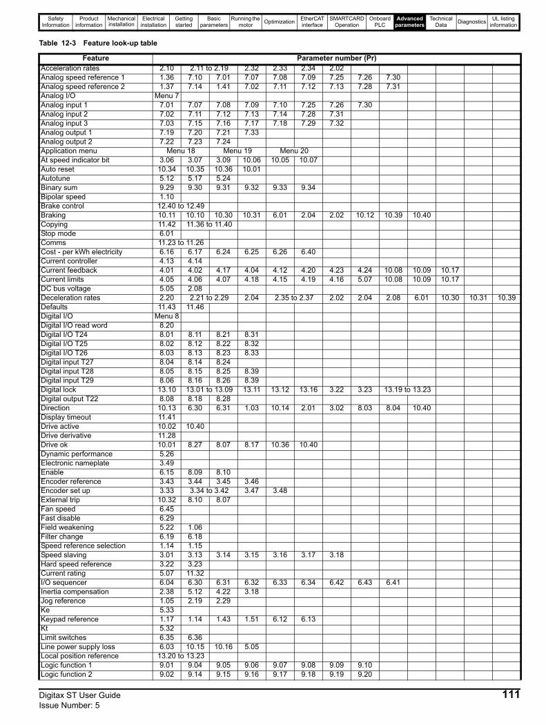
Safety Information
Product information
Mechanical installation
Electrical installation
Getting started
Basic parameters
Running the motor Optimization EtherCAT
interfaceSMARTCARD
OperationOnboard
PLCAdvanced
parametersTechnical
Data Diagnostics UL listing information
Table 12-3 Feature look-up table
Feature Parameter number (Pr)Acceleration rates 2.10 2.11 to 2.19 2.32 2.33 2.34 2.02Analog speed reference 1 1.36 7.10 7.01 7.07 7.08 7.09 7.25 7.26 7.30Analog speed reference 2 1.37 7.14 1.41 7.02 7.11 7.12 7.13 7.28 7.31Analog I/O Menu 7Analog input 1 7.01 7.07 7.08 7.09 7.10 7.25 7.26 7.30Analog input 2 7.02 7.11 7.12 7.13 7.14 7.28 7.31Analog input 3 7.03 7.15 7.16 7.17 7.18 7.29 7.32Analog output 1 7.19 7.20 7.21 7.33Analog output 2 7.22 7.23 7.24Application menu Menu 18 Menu 19 Menu 20At speed indicator bit 3.06 3.07 3.09 10.06 10.05 10.07Auto reset 10.34 10.35 10.36 10.01Autotune 5.12 5.17 5.24Binary sum 9.29 9.30 9.31 9.32 9.33 9.34Bipolar speed 1.10Brake control 12.40 to 12.49Braking 10.11 10.10 10.30 10.31 6.01 2.04 2.02 10.12 10.39 10.40Copying 11.42 11.36 to 11.40Stop mode 6.01Comms 11.23 to 11.26Cost - per kWh electricity 6.16 6.17 6.24 6.25 6.26 6.40Current controller 4.13 4.14Current feedback 4.01 4.02 4.17 4.04 4.12 4.20 4.23 4.24 10.08 10.09 10.17Current limits 4.05 4.06 4.07 4.18 4.15 4.19 4.16 5.07 10.08 10.09 10.17DC bus voltage 5.05 2.08Deceleration rates 2.20 2.21 to 2.29 2.04 2.35 to 2.37 2.02 2.04 2.08 6.01 10.30 10.31 10.39Defaults 11.43 11.46Digital I/O Menu 8Digital I/O read word 8.20Digital I/O T24 8.01 8.11 8.21 8.31Digital I/O T25 8.02 8.12 8.22 8.32Digital I/O T26 8.03 8.13 8.23 8.33Digital input T27 8.04 8.14 8.24Digital input T28 8.05 8.15 8.25 8.39Digital input T29 8.06 8.16 8.26 8.39Digital lock 13.10 13.01 to 13.09 13.11 13.12 13.16 3.22 3.23 13.19 to 13.23Digital output T22 8.08 8.18 8.28Direction 10.13 6.30 6.31 1.03 10.14 2.01 3.02 8.03 8.04 10.40Display timeout 11.41Drive active 10.02 10.40Drive derivative 11.28Drive ok 10.01 8.27 8.07 8.17 10.36 10.40Dynamic performance 5.26Electronic nameplate 3.49Enable 6.15 8.09 8.10Encoder reference 3.43 3.44 3.45 3.46Encoder set up 3.33 3.34 to 3.42 3.47 3.48External trip 10.32 8.10 8.07Fan speed 6.45Fast disable 6.29Field weakening 5.22 1.06Filter change 6.19 6.18Speed reference selection 1.14 1.15Speed slaving 3.01 3.13 3.14 3.15 3.16 3.17 3.18Hard speed reference 3.22 3.23Current rating 5.07 11.32I/O sequencer 6.04 6.30 6.31 6.32 6.33 6.34 6.42 6.43 6.41Inertia compensation 2.38 5.12 4.22 3.18Jog reference 1.05 2.19 2.29Ke 5.33Keypad reference 1.17 1.14 1.43 1.51 6.12 6.13Kt 5.32Limit switches 6.35 6.36Line power supply loss 6.03 10.15 10.16 5.05Local position reference 13.20 to 13.23Logic function 1 9.01 9.04 9.05 9.06 9.07 9.08 9.09 9.10Logic function 2 9.02 9.14 9.15 9.16 9.17 9.18 9.19 9.20
Digitax ST User Guide 111Issue Number: 5

Safety Information
Product information
Mechanical installation
Electrical installation
Getting started
Basic parameters
Running the motor Optimization EtherCAT
interfaceSMARTCARD
OperationOnboard
PLCAdvanced
parametersTechnical
Data Diagnostics UL listing information
Low voltage supply 6.44 6.46Marker pulse 3.32 3.31Maximum speed 1.06Menu 0 set up 11.01 to 11.22 Menu 22Minimum speed 1.07 10.04Motor map 5.07 5.08 5.09 5.11Motor map 2 Menu 21 11.45Motorized potentiometer 9.21 9.22 9.23 9.24 9.25 9.26 9.27 9.28Offset speed reference 1.04 1.38 1.09Onboard PLC 11.47 to 11.51Open collector digital outputs 8.30Orientation 13.10 13.13 to 13.15Output 5.01 5.02 5.03 5.04Overspeed threshold 3.08Phase angle 3.25 5.12PID controller Menu 14Position feedback - drive 3.28 3.29 3.30 3.50Positive logic 8.29Power up parameter 11.22 11.21Precision reference 1.18 1.19 1.20 1.44Preset speeds 1.15 1.21 to 1.28 1.16 1.14 1.42 1.45 to 1.48 1.50Programmable logic Menu 9Ramp (accel / decel) mode 2.04 2.08 6.01 2.02 2.03 10.30 10.31 10.39Rated speed autotune 5.08Regenerating 10.10 10.11 10.30 10.31 6.01 2.04 2.02 10.12 10.39 10.40Relative jog 13.17 to 13.19Relay output 8.07 8.17 8.27Reset 10.33 8.02 8.22 10.34 10.35 10.36 10.01S ramp 2.06 2.07Safe Torque Off input 8.09 8.10Sample rates 5.18Security code 11.30 11.44Serial comms 11.23 to 11.26Skip speeds 1.29 1.30 1.31 1.32 1.33 1.34 1.35SMARTCARD 11.36 to 11.40 11.42Software version 11.29 11.34Speed controller 3.10 to 3.17 3.19 3.20 3.21Speed feedback 3.02 3.03 3.04Speed feedback - drive 3.26 3.27 3.28 3.29 3.30 3.31 3.42Speed reference selection 1.14 1.15 1.49 1.50 1.01Status word 10.40Supply 6.44 5.05 6.46Switching frequency 5.18 5.35 7.34 7.35Thermal protection - drive 5.18 5.35 7.04 7.05 7.06 7.32 7.35 10.18Thermal protection - motor 4.15 5.07 4.19 4.16 4.25 7.15Thermistor input 7.15 7.03 10.37Threshold detector 1 12.01 12.03 to 12.07Threshold detector 2 12.02 12.23 to 12.27Time - filter change 6.19 6.18Time - powered up log 6.20 6.21 6.28Time - run log 6.22 6.23 6.28Torque 4.03 5.32Torque mode 4.08 4.11 4.09 4.10Trip detection 10.37 10.38 10.20 to 10.29Trip log 10.20 to 10.29 10.41 to 10.51 6.28Under voltage 5.05 10.16 10.15Variable selector 1 12.08 to 12.15Variable selector 2 12.28 to 12.35Velocity feed forward 1.39 1.40Voltage controller 5.31Voltage mode 5.14 5.17Voltage rating 11.33 5.09 5.05Voltage supply 6.44 6.46 5.05Warning 10.19 10.12 10.17 10.18 10.40Zero speed indicator bit 3.05 10.03
Feature Parameter number (Pr)
112 Digitax ST User Guide Issue Number: 5
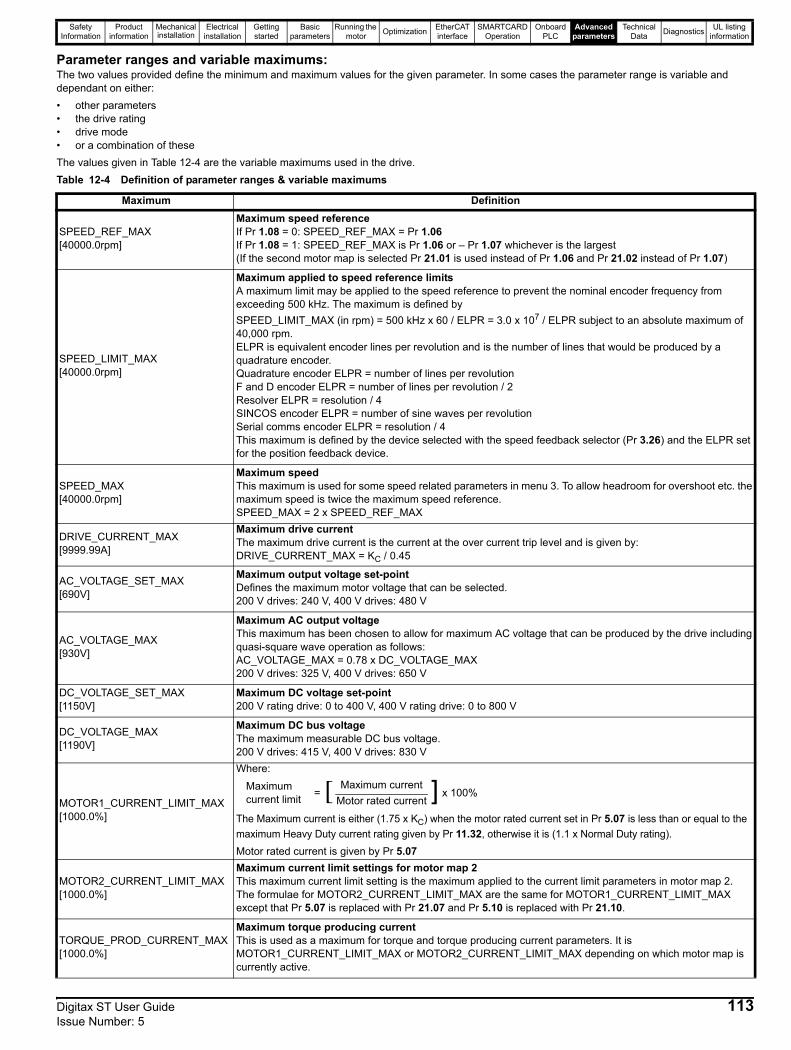
Safety Information
Product information
Mechanical installation
Electrical installation
Getting started
Basic parameters
Running the motor Optimization EtherCAT
interfaceSMARTCARD
OperationOnboard
PLCAdvanced
parametersTechnical
Data Diagnostics UL listing information
Parameter ranges and variable maximums:The two values provided define the minimum and maximum values for the given parameter. In some cases the parameter range is variable and dependant on either:• other parameters• the drive rating• drive mode• or a combination of theseThe values given in Table 12-4 are the variable maximums used in the drive.Table 12-4 Definition of parameter ranges & variable maximums
Maximum Definition
SPEED_REF_MAX[40000.0rpm]
Maximum speed referenceIf Pr 1.08 = 0: SPEED_REF_MAX = Pr 1.06If Pr 1.08 = 1: SPEED_REF_MAX is Pr 1.06 or – Pr 1.07 whichever is the largest(If the second motor map is selected Pr 21.01 is used instead of Pr 1.06 and Pr 21.02 instead of Pr 1.07)
SPEED_LIMIT_MAX[40000.0rpm]
Maximum applied to speed reference limitsA maximum limit may be applied to the speed reference to prevent the nominal encoder frequency from exceeding 500 kHz. The maximum is defined bySPEED_LIMIT_MAX (in rpm) = 500 kHz x 60 / ELPR = 3.0 x 10⁷ / ELPR subject to an absolute maximum of 40,000 rpm.ELPR is equivalent encoder lines per revolution and is the number of lines that would be produced by a quadrature encoder. Quadrature encoder ELPR = number of lines per revolutionF and D encoder ELPR = number of lines per revolution / 2Resolver ELPR = resolution / 4 SINCOS encoder ELPR = number of sine waves per revolutionSerial comms encoder ELPR = resolution / 4This maximum is defined by the device selected with the speed feedback selector (Pr 3.26) and the ELPR set for the position feedback device.
SPEED_MAX[40000.0rpm]
Maximum speedThis maximum is used for some speed related parameters in menu 3. To allow headroom for overshoot etc. the maximum speed is twice the maximum speed reference.SPEED_MAX = 2 x SPEED_REF_MAX
DRIVE_CURRENT_MAX[9999.99A]
Maximum drive current The maximum drive current is the current at the over current trip level and is given by: DRIVE_CURRENT_MAX = KC / 0.45
AC_VOLTAGE_SET_MAX[690V]
Maximum output voltage set-pointDefines the maximum motor voltage that can be selected. 200 V drives: 240 V, 400 V drives: 480 V
AC_VOLTAGE_MAX[930V]
Maximum AC output voltageThis maximum has been chosen to allow for maximum AC voltage that can be produced by the drive including quasi-square wave operation as follows:AC_VOLTAGE_MAX = 0.78 x DC_VOLTAGE_MAX200 V drives: 325 V, 400 V drives: 650 V
DC_VOLTAGE_SET_MAX[1150V]
Maximum DC voltage set-point200 V rating drive: 0 to 400 V, 400 V rating drive: 0 to 800 V
DC_VOLTAGE_MAX[1190V]
Maximum DC bus voltageThe maximum measurable DC bus voltage.200 V drives: 415 V, 400 V drives: 830 V
MOTOR1_CURRENT_LIMIT_MAX[1000.0%]
Where:
The Maximum current is either (1.75 x KC) when the motor rated current set in Pr 5.07 is less than or equal to the maximum Heavy Duty current rating given by Pr 11.32, otherwise it is (1.1 x Normal Duty rating). Motor rated current is given by Pr 5.07
MOTOR2_CURRENT_LIMIT_MAX[1000.0%]
Maximum current limit settings for motor map 2This maximum current limit setting is the maximum applied to the current limit parameters in motor map 2.The formulae for MOTOR2_CURRENT_LIMIT_MAX are the same for MOTOR1_CURRENT_LIMIT_MAX except that Pr 5.07 is replaced with Pr 21.07 and Pr 5.10 is replaced with Pr 21.10.
TORQUE_PROD_CURRENT_MAX[1000.0%]
Maximum torque producing currentThis is used as a maximum for torque and torque producing current parameters. It is MOTOR1_CURRENT_LIMIT_MAX or MOTOR2_CURRENT_LIMIT_MAX depending on which motor map is currently active.
Maximum current limit = [ Maximum current ] x 100%
Motor rated current
Digitax ST User Guide 113Issue Number: 5

Safety Information
Product information
Mechanical installation
Electrical installation
Getting started
Basic parameters
Running the motor Optimization EtherCAT
interfaceSMARTCARD
OperationOnboard
PLCAdvanced
parametersTechnical
Data Diagnostics UL listing information
USER_CURRENT_MAX[1000.0%]
Current parameter limit selected by the userThe user can select a maximum for Pr 4.08 (torque reference) and Pr 4.20 (percentage load) to give suitable scaling for analog I/O with Pr 4.24. This maximum is subject to a limit of MOTOR1_CURRENT_LIMIT_MAX. or MOTOR2_CURRENT_LIMIT_MAX depending on which motor map is currently active.USER_CURRENT_MAX = Pr 4.24
POWER_MAX[9999.99kW]
Maximum power in kWThe maximum power has been chosen to allow for the maximum power that can be output by the drive with maximum AC output voltage, maximum controlled current and unity power factor. Therefore POWER_MAX = √3 x AC_VOLTAGE_MAX x DRIVE_CURRENT_MAX
The values given in square brackets indicate the absolute maximum value allowed for the variable maximum.
Maximum Definition
114 Digitax ST User Guide Issue Number: 5

Safety Information
Product information
Mechanical installation
Electrical installation
Getting started
Basic parameters
Running the motor Optimization EtherCAT
interfaceSMARTCARD
OperationOnboard
PLCAdvanced
parametersTechnical
Data Diagnostics UL listing information
Digitax ST User Guide 115Issue Number: 5
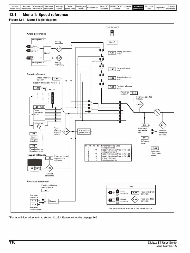
Safety Information
Product information
Mechanical installation
Electrical installation
Getting started
Basic parameters
Running the motor Optimization EtherCAT
interfaceSMARTCARD
OperationOnboard
PLCAdvanced
parametersTechnical
Data Diagnostics UL listing information
12.1 Menu 1: Speed referenceFigure 12-1 Menu 1 logic diagram
*For more information, refer to section 12.22.1 Reference modes on page 166
Preset reference*selector
Preset reference scan time
KeypadReference
Precision reference
Precision-reference update disable
Analog reference 1
Analog
reference 2
Analog reference 2 select
Preset reference select bits 1 ~ 3
Preset reference
Scan-timer reset
Analog input 1
Analog input 2
Memory
Menu 7
1.36
1.37
1.41
1.16
1.48
1.15
1.17
1.20
1.18
Precision reference trim
1.19
Preset reference select
Keypad reference select
Precision reference select
LOCAL/REMOTE
Menu 8
Level of referenceselected
Reference offset
Reference offset mode select
Reference*selector
Reference selected indicator
1.49
1.14
1.09
1.04
Reference percentage trim
1.38 1.01
Analog reference
Preset reference
Keypad reference
Precision reference
+
+
0.XX
0.XX
Key
Read-write (RW) parameter
Read-only (RO) parameter
Inputterminals
Outputterminals
The parameters are all shown in their default settings
1.51Power-up keypadcontrol modereference
1.20Preset reference selected indicator
Preset references 1 to 8
1.21 ~ 1.28
Scan timer
1.47 1.46 1.451.44
1.43
1.42
Pr set to greater than 1
1.501.50
Pr 1.491122345
Pr 1.501
>11
>1xxx
Reference being used
1.50
1.50
Analog reference 1Preset reference defined by Pr Analog reference 2Preset reference defined by Pr
Keypad referencePrecision reference
Preset reference defined by Pr 1.50
116 Digitax ST User Guide Issue Number: 5
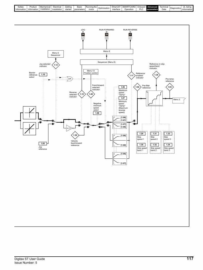
Safety Information
Product information
Mechanical installation
Electrical installation
Getting started
Basic parameters
Running the motor Optimization EtherCAT
interfaceSMARTCARD
OperationOnboard
PLCAdvanced
parametersTechnical
Data Diagnostics UL listing information
Jog reference
Bipolar reference select
Jog selected indicator
Menu 6Sequencer
1.10
1.05
1.13
Pre-filter reference
Pre-ramp reference
Maximum speed "clamp"
Minimum speed "clamp" (Maximum reverse speed)
Negative minimum speed select
Reference enabled indicator
Reverse selected indicator
Skip speed 1
Reference in skip speed band indicator
Velocity feed-forward reference
Feed-forward selected indicator
1.12
x(-1)
1.39
1.40
1.08
[1.06][1.07]
[1.07][1.06]
[1.06]
[1.06]
[1.06]
[1.07]
1.06
1.07
1.11
Sequencer (Menu 6)
1.02 1.03
Menu 2
Skip speed 2
Skip speed 3
Skip speedband 1
Skip speedband 2
Skip speedband 3
1.29
1.30
1.31
1.32
1.33
1.34
1.35
Menu 8
JOG RUN FORWARD RUN REVERSE
Menu 13Position control
Digitax ST User Guide 117Issue Number: 5

Safety Information
Product information
Mechanical installation
Electrical installation
Getting started
Basic parameters
Running the motor Optimization EtherCAT
interfaceSMARTCARD
OperationOnboard
PLCAdvanced
parametersTechnical
Data Diagnostics UL listing information
Parameter Range ( ) Default ( ) Type1.01 Speed reference selected ±SPEED_REF_MAX rpm RO Bi NC PT1.02 Pre-skip filter reference ±SPEED_REF_MAX rpm RO Bi NC PT1.03 Pre-ramp reference ±SPEED_REF_MAX rpm RO Bi NC PT1.04 Reference offset ±40,000.0 rpm 0.0 RW Bi US1.05 Jog reference {0.23} 0 to 4,000.0 rpm 0.0 RW Uni US1.06 Maximum reference clamp {0.02} SPEED_LIMIT_MAX rpm 3,000.0 RW Uni US1.07 Minimum reference clamp {0.01} ±SPEED_LIMIT_MAX rpm 0.0 RW Bi PT US
1.08 Negative minimum reference clamp enable OFF (0) or On (1) OFF (0) RW Bit US
1.09 Reference offset select OFF (0) or On (1) OFF (0) RW Bit US1.10 Bipolar reference enable {0.22} OFF (0) or On (1) OFF (0) RW Bit US1.11 Reference enabled indicator OFF (0) or On (1) RO Bit NC PT1.12 Reverse selected indicator OFF (0) or On (1) RO Bit NC PT1.13 Jog selected indicator OFF (0) or On (1) RO Bit NC PT
1.14 Reference selector {0.05} A1.A2 (0), A1.Pr (1), A2.Pr (2), Pr (3), PAd (4), Prc (5) A1.A2 (0) RW Txt US
1.15 Preset reference selector 0 to 9 0 RW Uni US
1.16 Preset reference selector timer 0 to 400.0s 10.0 RW Uni US
1.17 Keypad control mode reference ±SPEED_REF_MAX rpm 0.0 RO Bi NC PT PS
1.18 Precision reference coarse ±SPEED_REF_MAX rpm 0.0 RW Bi US1.19 Precision reference fine 0.000 to 0.099 rpm 0.000 RW Uni US
1.20 Precision reference update disable OFF (0) or On (1) OFF (0) RW Bit NC
1.21 Preset reference 1 {0.24} ±SPEED_REF_MAX rpm 0.0 RW Bi US1.22 Preset reference 2 {0.25} ±SPEED_REF_MAX rpm 0.0 RW Bi US1.23 Preset reference 3 ±SPEED_REF_MAX rpm 0.0 RW Bi US1.24 Preset reference 4 ±SPEED_REF_MAX rpm 0.0 RW Bi US1.25 Preset reference 5 ±SPEED_REF_MAX rpm 0.0 RW Bi US1.26 Preset reference 6 ±SPEED_REF_MAX rpm 0.0 RW Bi US1.27 Preset reference 7 ±SPEED_REF_MAX rpm 0.0 RW Bi US1.28 Preset reference 8 ±SPEED_REF_MAX rpm 0.0 RW Bi US1.29 Skip reference 1 0 to 40,000 rpm 0 RW Uni US1.30 Skip reference band 1 0 to 250 rpm 5 RW Uni US1.31 Skip reference 2 0 to 40,000 rpm 0 RW Uni US1.32 Skip reference band 2 0 to 250 rpm 5 RW Uni US1.33 Skip reference 3 0 to 40,000 rpm 0 RW Uni US1.34 Skip reference band 3 0 to 250 rpm 5 RW Uni US1.35 Reference in rejection zone OFF (0) or On (1) RO Bit NC PT1.36 Analog reference 1 ±SPEED_REF_MAX rpm RO Bi NC1.37 Analog reference 2 ±SPEED_REF_MAX rpm RO Bi NC1.38 Percentage trim ±100.00 % 0.00 RW Bi NC1.39 Velocity feed-forward ±40,000.0 rpm RO Bi NC PT1.40 Velocity feed-forward select OFF (0) or On (1) RO Bit NC PT1.41 Analog reference 2 select OFF (0) or On (1) OFF (0) RW Bit NC1.42 Preset reference select OFF (0) or On (1) OFF (0) RW Bit NC1.43 Keypad reference select OFF (0) or On (1) OFF (0) RW Bit NC1.44 Precision reference select OFF (0) or On (1) OFF (0) RW Bit NC1.45 Preset reference 1 select OFF (0) or On (1) OFF (0) RW Bit NC1.46 Preset reference 2 select OFF (0) or On (1) OFF (0) RW Bit NC1.47 Preset reference 3 select OFF (0) or On (1) OFF (0) RW Bit NC1.48 Reference timer reset flag OFF (0) or On (1) OFF (0) RW Bit NC1.49 Reference selected indicator 1 to 5 RO Uni NC PT
1.50 Preset reference selected indicator 1 to 8 RO Uni NC PT
1.51 Power-up keyboard control mode reference rESEt (0), LASt (1), PrS1 (2) rESEt (0) RW Txt US
RW Read / Write RO Read only Uni Unipolar Bi Bi-polar Bit Bit parameter Txt Text stringFI Filtered DE Destination NC Not copied RA Rating dependent PT Protected US User save PS Power down save
118 Digitax ST User Guide Issue Number: 5

Safety Information
Product information
Mechanical installation
Electrical installation
Getting started
Basic parameters
Running the motor Optimization EtherCAT
interfaceSMARTCARD
OperationOnboard
PLCAdvanced
parametersTechnical
Data Diagnostics UL listing information
Digitax ST User Guide 119Issue Number: 5
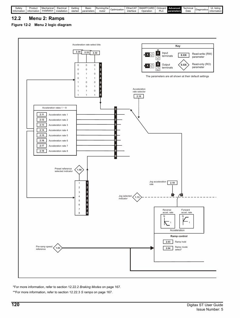
Safety Information
Product information
Mechanical installation
Electrical installation
Getting started
Basic parameters
Running the motor Optimization EtherCAT
interfaceSMARTCARD
OperationOnboard
PLCAdvanced
parametersTechnical
Data Diagnostics UL listing information
12.2 Menu 2: RampsFigure 12-2 Menu 2 logic diagram
0 0 0
0 0 1
0 1 0
0 1 1
1 0 0
1 0 1
1 1 0
1 1 1
Acceleration rate select bits
2.11 Acceleration rate 1
2.12 Acceleration rate 2
2.13 Acceleration rate 3
2.14 Acceleration rate 4
2.15 Acceleration rate 5
2.16 Acceleration rate 6
2.17 Acceleration rate 7
2.18 Acceleration rate 8
Acceleration rates 1 ~ 8
1.50
3
4
1
2
7
5
6
Preset referenceselected indicator
2.19Jog acceleration rate
1.13Jog selectedindicator
1.03Pre-ramp speedreference
2.03 Ramp hold
2.04 Ramp modeselect*
N
t
N
t
Acceleration
Reverse accel. rate
Forward accel. rate
Ramp control
2.10
Accelerationrate selector
2.34 2.322.33 2.32
0.XX
0.XX
Key
Read-write (RW) parameter
Read-only (RO) parameter
Inputterminals
Outputterminals
The parameters are all shown at their default settings
8
*For more information, refer to section 12.22.2 Braking Modes on page 167.**For more information, refer to section 12.22.3 S ramps on page 167.
120 Digitax ST User Guide Issue Number: 5
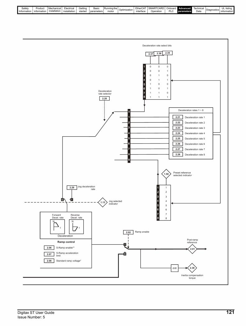
Safety Information
Product information
Mechanical installation
Electrical installation
Getting started
Basic parameters
Running the motor Optimization EtherCAT
interfaceSMARTCARD
OperationOnboard
PLCAdvanced
parametersTechnical
Data Diagnostics UL listing information
2.06 S-Ramp enable**
2.07 S-Ramp acceleration limit
2.08 Standard ramp voltage*
Ramp control
N
t
N
t
Deceleration
Forward Decel. rate
Reverse Decel. rate
2.01
Post-rampreference
2.02 Ramp enable
Deceleration rate select bits
2.21 Deceleration rate 1
2.22 Deceleration rate 2
2.23 Deceleration rate 3
2.24 Deceleration rate 4
2.25 Deceleration rate 5
2.26 Deceleration rate 6
2.27 Deceleration rate 7
2.28 Deceleration rate 8
Deceleration rates 1 ~ 8
3
4
1
2
7
8
5
6
2.37
1.50 Preset referenceselected indicator
2.29 Jog deceleration rate
1.13 Jog selectedindicator
2.38
Inertia compensationtorque
d/dt
2.20
Decelerationrate selector
2.36 2.35
Digitax ST User Guide 121Issue Number: 5
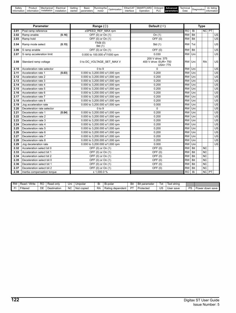
Safety Information
Product information
Mechanical installation
Electrical installation
Getting started
Basic parameters
Running the motor Optimization EtherCAT
interfaceSMARTCARD
OperationOnboard
PLCAdvanced
parametersTechnical
Data Diagnostics UL listing information
Parameter Range ( ) Default ( ) Type2.01 Post ramp reference ±SPEED_REF_MAX rpm RO Bi NC PT2.02 Ramp enable {0.16} OFF (0) or On (1) On (1) RW Bit US2.03 Ramp hold OFF (0) or On (1) OFF (0) RW Bit US
2.04 Ramp mode select {0.15} FASt (0)Std (1) Std (1) RW Txt US
2.06 S ramp enable OFF (0) or On (1) OFF (0) RW Bit US2.07 S ramp acceleration limit 0.000 to 100.000 s2/1000 rpm 0.030 RW Uni US
2.08 Standard ramp voltage 0 to DC_VOLTAGE_SET_MAX V200 V drive: 375
400 V drive: EUR> 750 USA> 775
RW Uni RA US
2.10 Acceleration rate selector 0 to 9 0 RW Uni US2.11 Acceleration rate 1 {0.03} 0.000 to 3,200.000 s/1,000 rpm 0.200 RW Uni US2.12 Acceleration rate 2 0.000 to 3,200.000 s/1,000 rpm 0.200 RW Uni US2.13 Acceleration rate 3 0.000 to 3,200.000 s/1,000 rpm 0.200 RW Uni US2.14 Acceleration rate 4 0.000 to 3,200.000 s/1,000 rpm 0.200 RW Uni US2.15 Acceleration rate 5 0.000 to 3,200.000 s/1,000 rpm 0.200 RW Uni US2.16 Acceleration rate 6 0.000 to 3,200.000 s/1,000 rpm 0.200 RW Uni US2.17 Acceleration rate 7 0.000 to 3,200.000 s/1,000 rpm 0.200 RW Uni US2.18 Acceleration rate 8 0.000 to 3,200.000 s/1,000 rpm 0.200 RW Uni US2.19 Jog acceleration rate 0.000 to 3,200.000 s/1,000 rpm 0.000 RW Uni US2.20 Deceleration rate selector 0 to 9 0 RW Uni US2.21 Deceleration rate 1 {0.04} 0.000 to 3,200.000 s/1,000 rpm 0.200 RW Uni US2.22 Deceleration rate 2 0.000 to 3,200.000 s/1,000 rpm 0.200 RW Uni US2.23 Deceleration rate 3 0.000 to 3,200.000 s/1,000 rpm 0.200 RW Uni US2.24 Deceleration rate 4 0.000 to 3,200.000 s/1,000 rpm 0.200 RW Uni US2.25 Deceleration rate 5 0.000 to 3,200.000 s/1,000 rpm 0.200 RW Uni US2.26 Deceleration rate 6 0.000 to 3,200.000 s/1,000 rpm 0.200 RW Uni US2.27 Deceleration rate 7 0.000 to 3,200.000 s/1,000 rpm 0.200 RW Uni US2.28 Deceleration rate 8 0.000 to 3,200.000 s/1,000 rpm 0.200 RW Uni US2.29 Jog deceleration rate 0.000 to 3,200.000 s/1,000 rpm 0.000 RW Uni US2.32 Acceleration select bit 0 OFF (0) or On (1) OFF (0) RW Bit NC2.33 Acceleration select bit 1 OFF (0) or On (1) OFF (0) RW Bit NC2.34 Acceleration select bit 2 OFF (0) or On (1) OFF (0) RW Bit NC2.35 Deceleration select bit 0 OFF (0) or On (1) OFF (0) RW Bit NC2.36 Deceleration select bit 1 OFF (0) or On (1) OFF (0) RW Bit NC2.37 Deceleration select bit 2 OFF (0) or On (1) OFF (0) RW Bit NC2.38 Inertia compensation torque ± 1,000.0 % RO Bi NC PT
RW Read / Write RO Read only Uni Unipolar Bi Bi-polar Bit Bit parameter Txt Text stringFI Filtered DE Destination NC Not copied RA Rating dependent PT Protected US User save PS Power down save
122 Digitax ST User Guide Issue Number: 5

Safety Information
Product information
Mechanical installation
Electrical installation
Getting started
Basic parameters
Running the motor Optimization EtherCAT
interfaceSMARTCARD
OperationOnboard
PLCAdvanced
parametersTechnical
Data Diagnostics UL listing information
Digitax ST User Guide 123Issue Number: 5
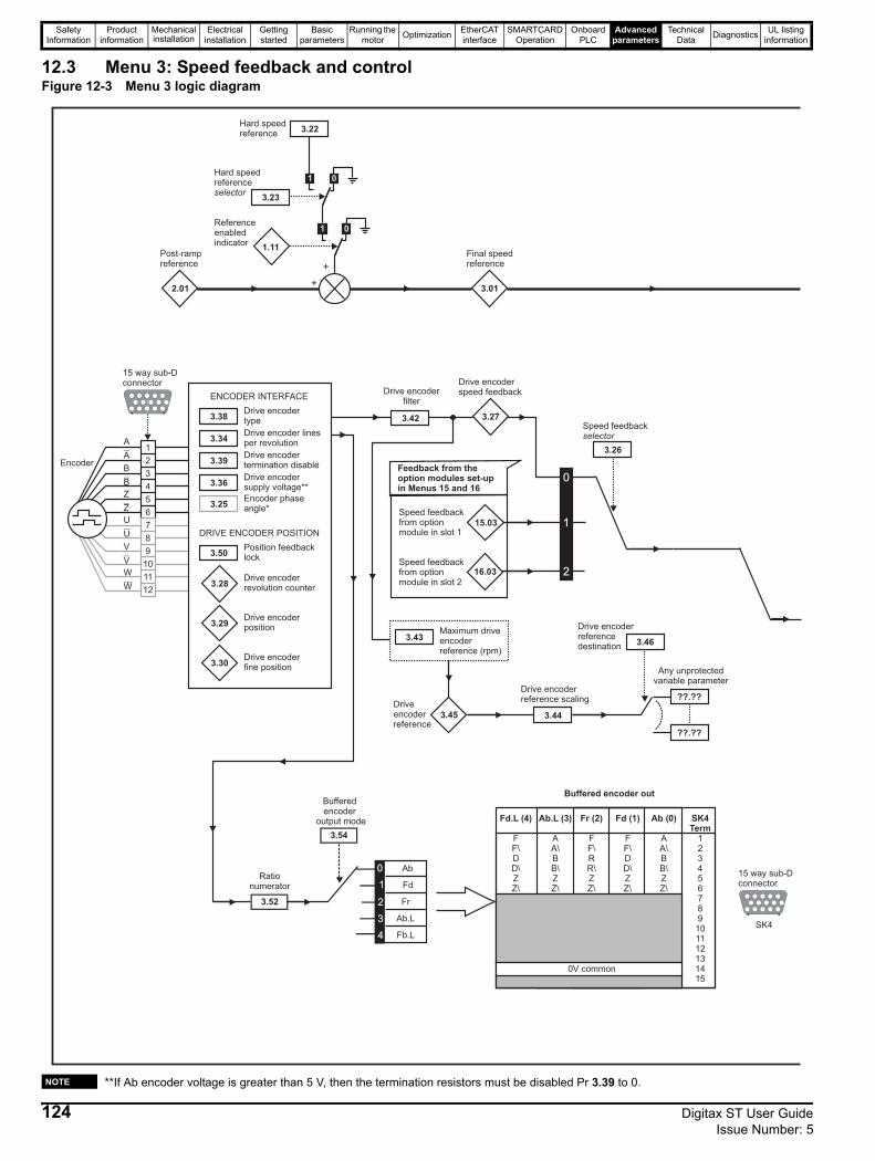
Safety Information
Product information
Mechanical installation
Electrical installation
Getting started
Basic parameters
Running the motor Optimization EtherCAT
interfaceSMARTCARD
OperationOnboard
PLCAdvanced
parametersTechnical
Data Diagnostics UL listing information
12.3 Menu 3: Speed feedback and controlFigure 12-3 Menu 3 logic diagram
**If Ab encoder voltage is greater than 5 V, then the termination resistors must be disabled Pr 3.39 to 0.
15 way sub-Dconnector
Encoder
1
2
3
4
5
6
A
A
B
B
Z
Z
U
U
V
V
W
W
7
8
9
10
11
12
3.38Drive encodertype
3.34Drive encoder linesper revolution
3.39Drive encodertermination disable
3.36Drive encodersupply voltage**
3.25Encoder phaseangle*
ENCODER INTERFACE
DRIVE ENCODER POSITION
3.28Drive encoderrevolution counter
3.29Drive encoderposition
3.30Drive encoderfine position
2.01
Post-rampreference
+
+
01
01
3.23
1.11
Hard speedreferenceselector
Referenceenabledindicator
3.01
Final speedreference
3.22Hard speedreference
3.50Position feedbacklock
15.03
Speed feedbackfrom optionmodule in slot 1
16.03Speed feedbackfrom optionmodule in slot 2
Feedback from theoption modules set-upin Menus 15 and 16
3.27
Drive encoderspeed feedback
0
1
2
3.26
Speed feedbackselector
3.45 3.44
Any unprotectedvariable parameter
??.??
??.??
3.46
Driveencoderreference
Drive encoderreference scaling
Drive encoderreferencedestination
3.43Maximum driveencoderreference (rpm)
3.42
Drive encoderfilter
1
Bufferedencoder
output mode
3.52
Rationumerator 1
2
Fd
Fr
Ab.L3
0 Ab
4 Fb.L
SK4Term
123456789
101112131415
Ab (0)
AA\BB\ZZ\
Fd (1)
FF\DD\ZZ\
Fr (2)
FF\RR\ZZ\
Ab.L (3)
AA\BB\ZZ\
Fd.L (4)
FF\DD\ZZ\
0V common
Buffered encoder out
15 way sub-Dconnector
SK4
3.54
NOTE
124 Digitax ST User Guide Issue Number: 5

Safety Information
Product information
Mechanical installation
Electrical installation
Getting started
Basic parameters
Running the motor Optimization EtherCAT
interfaceSMARTCARD
OperationOnboard
PLCAdvanced
parametersTechnical
Data Diagnostics UL listing information
+
_
3.03
Speederror
+
_
Speed loop gains
3.04
Speedcontrolleroutput
Menu 4
+
_Overspeed trip(O.SPd)1.06
Max reference clamp
+
_
3.0610.05
Below at-speedwindow indicatorAt speed
lower limit
+
_3.07
10.07Above at-speedwindow indicator
At speedupper limit
10.06
At speedindicator
NOR
+
_
3.0510.03
At zero speedindicator
Zero speedthreshold
+
_
1.07 10.04
At or below min.speed indicatorMinimum
speed
0
1
1.10
Bipolar referenceselect
+5min-1
+20%
1.03
Pre rampreference
3.09
Absolute at-speeddetect mode
0
1
Speed controllerdifferentialfeedback gains
0.XX
0.XX
Key
Read-write (RW)parameter
Read-only (RO)parameter
Inputterminals
Outputterminals
XX
XX
The parameters are all shown at their default settings
0
1
3.08
Overspeed threshold
3.08 >0
Speed controllergain select
3.10
3.11 (Ki1)
(Kp1)
3.13
3.14 (Ki2)
(Kp2)
3.16
Speed feedback
3.02
+
_
(Kd1) (Kd2)
3.153.12
0
1
10
Digitax ST User Guide 125Issue Number: 5
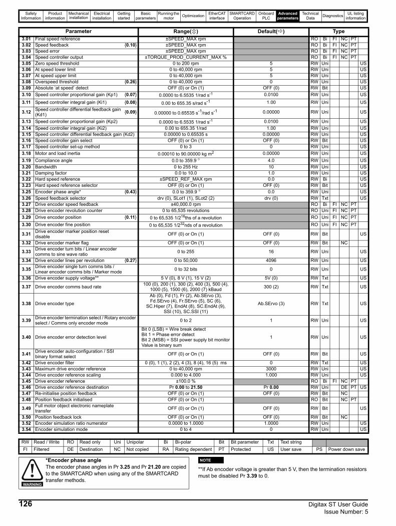
Safety Information
Product information
Mechanical installation
Electrical installation
Getting started
Basic parameters
Running the motor Optimization EtherCAT
interfaceSMARTCARD
OperationOnboard
PLCAdvanced
parametersTechnical
Data Diagnostics UL listing information
**If Ab encoder voltage is greater than 5 V, then the termination resistors must be disabled Pr 3.39 to 0.
Parameter Range( ) Default( ) Type3.01 Final speed reference ±SPEED_MAX rpm RO Bi FI NC PT3.02 Speed feedback {0.10} ±SPEED_MAX rpm RO Bi FI NC PT3.03 Speed error ±SPEED_MAX rpm RO Bi FI NC PT3.04 Speed controller output ±TORQUE_PROD_CURRENT_MAX % RO Bi FI NC PT3.05 Zero speed threshold 0 to 200 rpm 5 RW Uni US3.06 At speed lower limit 0 to 40,000 rpm 5 RW Uni US3.07 At speed upper limit 0 to 40,000 rpm 5 RW Uni US3.08 Overspeed threshold {0.26} 0 to 40,000 rpm 0 RW Uni US3.09 Absolute ‘at speed’ detect OFF (0) or On (1) OFF (0) RW Bit US3.10 Speed controller proportional gain (Kp1) {0.07} 0.0000 to 6.5535 1/rad s-1 0.0100 RW Uni US3.11 Speed controller integral gain (Ki1) {0.08} 0.00 to 655.35 s/rad s-1 1.00 RW Uni US
3.12 Speed controller differential feedback gain (Kd1) {0.09} 0.00000 to 0.65535 s-1/rad s-1 0.00000 RW Uni US
3.13 Speed controller proportional gain (Kp2) 0.0000 to 6.5535 1/rad s-1 0.0100 RW Uni US3.14 Speed controller integral gain (Ki2) 0.00 to 655.35 1/rad 1.00 RW Uni US3.15 Speed controller differential feedback gain (Kd2) 0.00000 to 0.65535 s 0.00000 RW Uni US3.16 Speed controller gain select OFF (0) or On (1) OFF (0) RW Bit US3.17 Speed controller set-up method 0 to 3 0 RW Uni US3.18 Motor and load inertia 0.00010 to 90.00000 kg m2 0.00000 RW Uni US3.19 Compliance angle 0.0 to 359.9 ° 4.0 RW Uni US3.20 Bandwidth 0 to 255 Hz 10 RW Uni US3.21 Damping factor 0.0 to 10.0 1.0 RW Uni US3.22 Hard speed reference ±SPEED_REF_MAX rpm 0.0 RW Bi US3.23 Hard speed reference selector OFF (0) or On (1) OFF (0) RW Bit US3.25 Encoder phase angle* {0.43} 0.0 to 359.9 ° 0.0 RW Uni US3.26 Speed feedback selector drv (0), SLot1 (1), SLot2 (2) drv (0) RW Txt US3.27 Drive encoder speed feedback ±40,000.0 rpm RO Bi FI NC PT3.28 Drive encoder revolution counter 0 to 65,535 revolutions RO Uni FI NC PT3.29 Drive encoder position {0.11} 0 to 65,535 1/216ths of a revolution RO Uni FI NC PT3.30 Drive encoder fine position 0 to 65,535 1/232nds of a revolution RO Uni FI NC PT
3.31 Drive encoder marker position reset disable OFF (0) or On (1) OFF (0) RW Bit US
3.32 Drive encoder marker flag OFF (0) or On (1) OFF (0) RW Bit NC
3.33 Drive encoder turn bits / Linear encoder comms to sine wave ratio 0 to 255 16 RW Uni US
3.34 Drive encoder lines per revolution {0.27} 0 to 50,000 4096 RW Uni US
3.35 Drive encoder single turn comms bits / Linear encoder comms bits / Marker mode 0 to 32 bits 0 RW Uni US
3.36 Drive encoder supply voltage** 5 V (0), 8 V (1), 15 V (2) 5V (0) RW Txt US
3.37 Drive encoder comms baud rate 100 (0), 200 (1), 300 (2), 400 (3), 500 (4), 1000 (5), 1500 (6), 2000 (7) kBaud 300 (2) RW Txt US
3.38 Drive encoder type
Ab (0), Fd (1), Fr (2), Ab.SErvo (3), Fd.SErvo (4), Fr.SErvo (5), SC (6),
SC.Hiper (7), EndAt (8), SC.EndAt (9), SSI (10), SC.SSI (11)
Ab.SErvo (3) RW Txt US
3.39 Drive encoder termination select / Rotary encoder select / Comms only encoder mode 0 to 2 1 RW Uni US
3.40 Drive encoder error detection level
Bit 0 (LSB) = Wire break detectBit 1 = Phase error detectBit 2 (MSB) = SSI power supply bit monitorValue is binary sum
1 RW Uni US
3.41 Drive encoder auto-configuration / SSI binary format select OFF (0) or On (1) OFF (0) RW Bit US
3.42 Drive encoder filter 0 (0), 1 (1), 2 (2), 4 (3), 8 (4), 16 (5) ms 0 RW Txt US3.43 Maximum drive encoder reference 0 to 40,000 rpm 3000 RW Uni US3.44 Drive encoder reference scaling 0.000 to 4.000 1.000 RW Uni US3.45 Drive encoder reference ±100.0 % RO Bi FI NC PT3.46 Drive encoder reference destination Pr 0.00 to 21.50 Pr 0.00 RW Uni DE PT US3.47 Re-initialise position feedback OFF (0) or On (1) OFF (0) RW Bit NC3.48 Position feedback initialised OFF (0) or On (1) RO Bit NC PT
3.49 Full motor object electronic nameplate transfer OFF (0) or On (1) OFF (0) RW Bit US
3.50 Position feedback lock OFF (0) or On (1) OFF (0) RW Bit NC3.52 Encoder simulation ratio numerator 0.0000 to 1.0000 1.0000 RW Uni US3.54 Encoder simulation mode 0 to 4 0 RW Uni US
RW Read / Write RO Read only Uni Unipolar Bi Bi-polar Bit Bit parameter Txt Text stringFI Filtered DE Destination NC Not copied RA Rating dependent PT Protected US User save PS Power down save
*Encoder phase angle The encoder phase angles in Pr 3.25 and Pr 21.20 are copied to the SMARTCARD when using any of the SMARTCARD transfer methods.
WARNING
NOTE
126 Digitax ST User Guide Issue Number: 5

Safety Information
Product information
Mechanical installation
Electrical installation
Getting started
Basic parameters
Running the motor Optimization EtherCAT
interfaceSMARTCARD
OperationOnboard
PLCAdvanced
parametersTechnical
Data Diagnostics UL listing information
12.4 Menu 4: Torque and current controlFigure 12-4 Menu 4 logic diagram
*For more information, refer to section 12.22.4 Torque modes on page 168.
4.04
Currentdemand
Filter
+
_
4.08
4.09
10.0910.08
4.13
4.14
Current loopP gain
Current loopI gain
Current controller
4.18
11.32
5.07
4.05
4.06
Motoring
Regenerating
Current limits
4.07 Symmetrical
Drive ratedcontinuous
current
Motor ratedcurrent
Over-ridingcurrent limit
3.05Zero
speedthreshold
Torque referenceoffset
Torquereference*
Speedover-ride
level
Coiler/uncoilerspeed
over-ridelevel
+
At 100%load
indicator
Current limitactive
indicator
Motor activecurrent
4.02
10.174.19
Motoroverload
accumulator
Motor currentoverload alarm
indicator
10.39
Braking energyoverloadindicator
Torque modeselector
4.11
4.10
Torquereference
offsetenable
+
0
1
2
3
4
+
+
4.03
Torquedemand
0.XX
0.XX
Key
Read-write (RW)parameter
Read-only (RO)parameter
Inputterminals
Outputterminals
XX
XX
Percentageload
4.20
The parameters are all shown at their default settings
4.23
Currentdemandfilter 1
4.12
Currentdemandfilter 2
4.15 4.16
Motor thermaltime constant
Motor protectionmode
4.24
4.25
Low speedprotection mode
Overload detection
User currentmax scaling
Speed controllergain select
3.16
1.03Pre-rampreference
3.04+
3.01
3.02
Speedfeedback
Finalspeeddemand
_Speed loop
output
+
+
4.22
2.38
Inertiacompensation
enable
+
Inertiacompensation
torque
Digitax ST User Guide 127Issue Number: 5
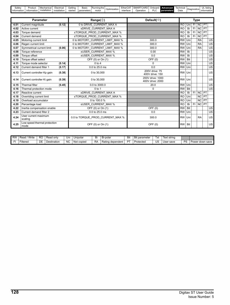
Safety Information
Product information
Mechanical installation
Electrical installation
Getting started
Basic parameters
Running the motor Optimization EtherCAT
interfaceSMARTCARD
OperationOnboard
PLCAdvanced
parametersTechnical
Data Diagnostics UL listing information
Parameter Range( ) Default( ) Type4.01 Current magnitude {0.12} 0 to DRIVE_CURRENT_MAX A RO Uni FI NC PT4.02 Active current ±DRIVE_CURRENT_MAX A RO Bi FI NC PT4.03 Torque demand ±TORQUE_PROD_CURRENT_MAX % RO Bi FI NC PT4.04 Current demand ±TORQUE_PROD_CURRENT_MAX % RO Bi FI NC PT4.05 Motoring current limit 0 to MOTOR1_CURRENT_LIMIT_MAX % 300.0 RW Uni RA US4.06 Regen current limit 0 to MOTOR1_CURRENT_LIMIT_MAX % 300.0 RW Uni RA US4.07 Symmetrical current limit {0.06} 0 to MOTOR1_CURRENT_LIMIT_MAX % 300.0 RW Uni RA US4.08 Torque reference ±USER_CURRENT_MAX % 0.00 RW Bi US4.09 Torque offset ±USER_CURRENT_MAX % 0.0 RW Bi US4.10 Torque offset select OFF (0) or On (1) OFF (0) RW Bit US4.11 Torque mode selector {0.14} 0 to 4 0 RW Uni US4.12 Current demand filter 1 {0.17} 0.0 to 25.0 ms 0.0 RW Uni US
4.13 Current controller Kp gain {0.38} 0 to 30,000 200V drive: 75400V drive: 150 RW Uni US
4.14 Current controller Ki gain {0.39} 0 to 30,000 200V drive: 1000400V drive: 2000 RW Uni US
4.15 Thermal filter {0.45} 0.0 to 3000.0 20.0 RW Uni US4.16 Thermal protection mode 0 to 1 0 RW Bit US4.17 Reactive current ±DRIVE_CURRENT_MAX A RO Bi FI NC PT4.18 Overriding current limit ±TORQUE_PROD_CURRENT_MAX % RO Uni NC PT4.19 Overload accumulator 0 to 100.0 % RO Uni NC PT4.20 Percentage load ±USER_CURRENT_MAX % RO Bi FI NC PT4.22 Inertia compensation enable OFF (0) or On (1) OFF (0) RW Bit US4.23 Current demand filter 2 0.0 to 25.0 ms 0.0 RW Uni US
4.24 User current maximum scaling 0.0 to TORQUE_PROD_CURRENT_MAX % 300.0 RW Uni RA US
4.25 Low speed thermal protection mode OFF (0) or On (1) OFF (0) RW Bit US
RW Read / Write RO Read only Uni Unipolar Bi Bi-polar Bit Bit parameter Txt Text stringFI Filtered DE Destination NC Not copied RA Rating dependent PT Protected US User save PS Power down save
128 Digitax ST User Guide Issue Number: 5

Safety Information
Product information
Mechanical installation
Electrical installation
Getting started
Basic parameters
Running the motor Optimization EtherCAT
interfaceSMARTCARD
OperationOnboard
PLCAdvanced
parametersTechnical
Data Diagnostics UL listing information
Digitax ST User Guide 129Issue Number: 5
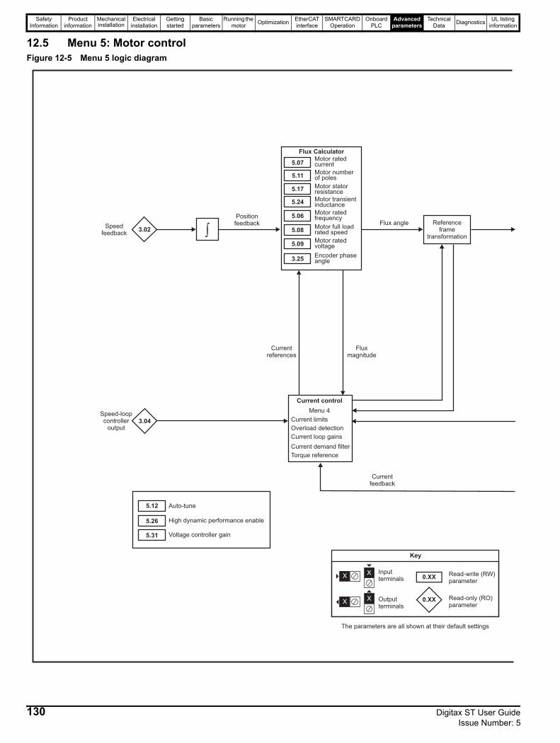
Safety Information
Product information
Mechanical installation
Electrical installation
Getting started
Basic parameters
Running the motor Optimization EtherCAT
interfaceSMARTCARD
OperationOnboard
PLCAdvanced
parametersTechnical
Data Diagnostics UL listing information
12.5 Menu 5: Motor controlFigure 12-5 Menu 5 logic diagram
3.04
3.25Encoder phaseangle
5.06Motor ratedfrequency
5.08Motor full loadrated speed
5.09Motor ratedvoltage
5.07Motor ratedcurrent
5.11Motor numberof poles
5.17 Motor statorresistance
5.24 Motor transientinductance
Flux Calculator
Current limits
Current control
Overload detection
Current loop gains
Torque reference
Current demand filter
Menu 4
Referenceframe
transformation3.02
Speedfeedback
Speed-loopcontroller
output
Positionfeedback
Fluxmagnitude
Currentreferences
Currentfeedback
Flux angle
5.12
5.26
5.31
Auto-tune
High dynamic performance enable
Voltage controller gain
0.XX
0.XX
Key
Read-write (RW)parameter
Read-only (RO)parameter
Inputterminals
Outputterminals
XX
XX
The parameters are all shown at their default settings
�
130 Digitax ST User Guide Issue Number: 5
Safety Information
Product information
Mechanical installation
Electrical installation
Getting started
Basic parameters
Running the motor Optimization EtherCAT
interfaceSMARTCARD
OperationOnboard
PLCAdvanced
parametersTechnical
Data Diagnostics UL listing information
4.02
4.17
4.01
5.09Motor ratedvoltage
5.21Field gainreduction
Flux Controller
5.18Maximum switchingfrequency
Modulator
5.03Power calculation (V x 1)
5.02Outputvoltage
Outputpower
5.05
Voltage reference
U
V
W
DC busvoltage
Motorcurrentmagnitude
Reactive current
Motor activecurrent
5.35Disable autoswitchingfrequencychange
5.22High speedservo modeenable
Digitax ST User Guide 131Issue Number: 5
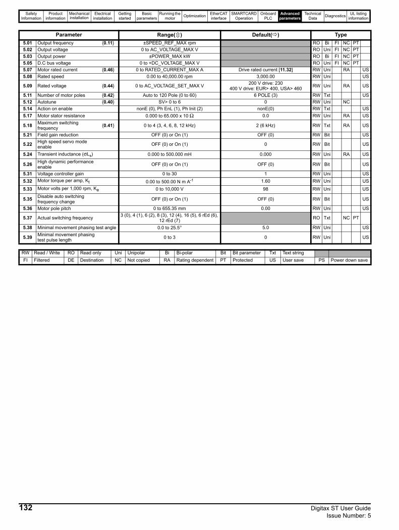
Safety Information
Product information
Mechanical installation
Electrical installation
Getting started
Basic parameters
Running the motor Optimization EtherCAT
interfaceSMARTCARD
OperationOnboard
PLCAdvanced
parametersTechnical
Data Diagnostics UL listing information
Parameter Range( ) Default( ) Type5.01 Output frequency {0.11} ±SPEED_REF_MAX rpm RO Bi FI NC PT5.02 Output voltage 0 to AC_VOLTAGE_MAX V RO Uni FI NC PT5.03 Output power ±POWER_MAX kW RO Bi FI NC PT5.05 D.C bus voltage 0 to +DC_VOLTAGE_MAX V RO Uni FI NC PT5.07 Motor rated current {0.46} 0 to RATED_CURRENT_MAX A Drive rated current [11.32] RW Uni RA US5.08 Rated speed 0.00 to 40,000.00 rpm 3,000.00 RW Uni US
5.09 Rated voltage {0.44} 0 to AC_VOLTAGE_SET_MAX V 200 V drive: 230400 V drive: EUR> 400, USA> 460 RW Uni RA US
5.11 Number of motor poles {0.42} Auto to 120 Pole (0 to 60) 6 POLE (3) RW Txt US5.12 Autotune {0.40} SV> 0 to 6 0 RW Uni NC5.14 Action on enable nonE (0), Ph EnL (1), Ph Init (2) nonE(0) RW Txt US5.17 Motor stator resistance 0.000 to 65.000 x 10 Ω 0.0 RW Uni RA US
5.18 Maximum switching frequency {0.41} 0 to 4 (3, 4, 6, 8, 12 kHz) 2 (6 kHz) RW Txt RA US
5.21 Field gain reduction OFF (0) or On (1) OFF (0) RW Bit US
5.22 High speed servo mode enable OFF (0) or On (1) 0 RW Bit US
5.24 Transient inductance (σLs) 0.000 to 500.000 mH 0.000 RW Uni RA US
5.26 High dynamic performance enable OFF (0) or On (1) OFF (0) RW Bit US
5.31 Voltage controller gain 0 to 30 1 RW Uni US5.32 Motor torque per amp, Kt 0.00 to 500.00 N m A-1 1.60 RW Uni US
5.33 Motor volts per 1,000 rpm, Ke 0 to 10,000 V 98 RW Uni US
5.35 Disable auto switching frequency change OFF (0) or On (1) OFF (0) RW Bit US
5.36 Motor pole pitch 0 to 655.35 mm 0.00 RW Uni US
5.37 Actual switching frequency 3 (0), 4 (1), 6 (2), 8 (3), 12 (4), 16 (5), 6 rEd (6), 12 rEd (7) RO Txt NC PT
5.38 Minimal movement phasing test angle 0.0 to 25.5° 5.0 RW Uni US
5.39 Minimal movement phasing test pulse length 0 to 3 0 RW Uni US
RW Read / Write RO Read only Uni Unipolar Bi Bi-polar Bit Bit parameter Txt Text stringFI Filtered DE Destination NC Not copied RA Rating dependent PT Protected US User save PS Power down save
132 Digitax ST User Guide Issue Number: 5
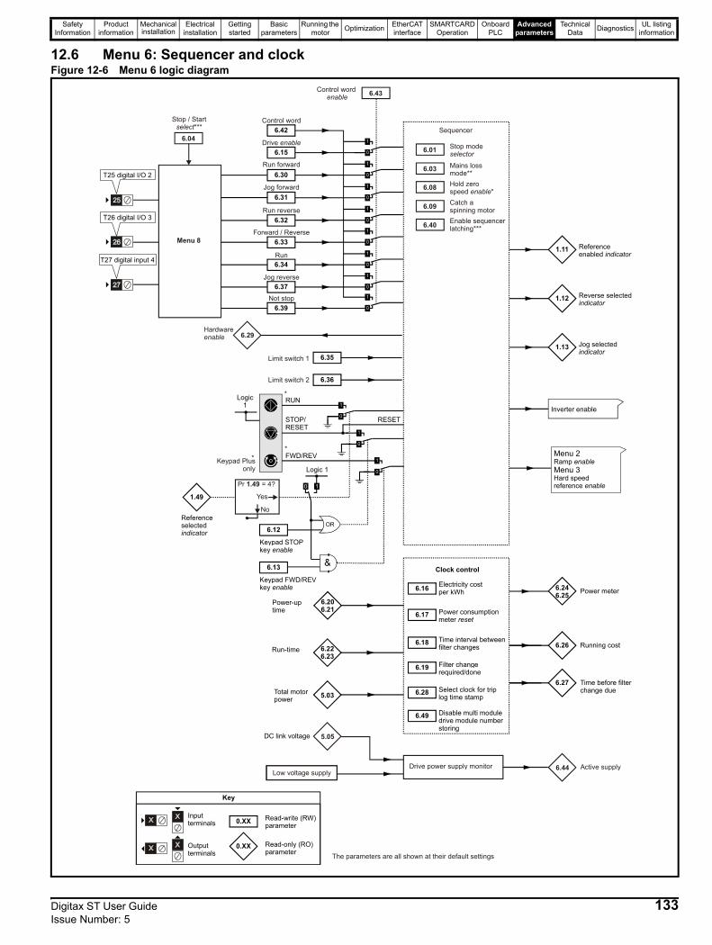
Safety Information
Product information
Mechanical installation
Electrical installation
Getting started
Basic parameters
Running the motor Optimization EtherCAT
interfaceSMARTCARD
OperationOnboard
PLCAdvanced
parametersTechnical
Data Diagnostics UL listing information
12.6 Menu 6: Sequencer and clockFigure 12-6 Menu 6 logic diagram
6.15
6.30
6.31
6.32
6.33
6.42
6.34
6.37
Logic 1
6.12
Keypad STOP key enable
6.13
Keypad FWD/REV key enable
1.11 Reference enabled indicator
1.12 Reverse selected indicator
1.13 Jog selected indicator
RUN
STOP/ RESET
FWD/REV
RESET
1.49
Reference selected indicator
Logic 1
6.17 Power consumption meter reset
6.18 Time interval betweenfilter changes
6.19 Filter change required/done
6.28 Select clock for triplog time stamp
6.16 Electricity costper kWh
Clock control
6.246.25 Power meter
6.26 Running cost
6.27 Time before filter change due
Inverter enable
Menu 2
Menu 3Ramp
Hard speed reference
enable
enable
6.206.21
Power-up time
6.226.23
Run-time
5.03Total motorpower
0.XX
0.XX
Key
Read-write (RW) parameter
Read-only (RO) parameter
Inputterminals
Outputterminals The parameters are all shown at their default settings
Pr = 4?1.49
6.43
0 1
Jog reverse
Run
Forward / Reverse
Run reverse
Jog forward
Run forward
Drive enable
Control word
Control word enable
6.35
6.36Limit switch 2
Limit switch 1
6.29Hardwareenable
Menu 8
6.04
Stop / Start***select Sequencer
6.01
6.03
6.08
6.09
6.40
Stop modeselector
Mains loss mode**Hold zero speed *enableCatch a spinning motorEnable sequencerlatching***
5.05DC link voltage
Low voltage supplyDrive power supply monitor 6.44 Active supply
T25 digital I/O 2
T26 digital I/O 3
T27 digital input 4
6.39Not stop
*
**Keypad Plus
only
Yes
No
6.49 Disable multi moduledrive module numberstoring
Digitax ST User Guide 133Issue Number: 5
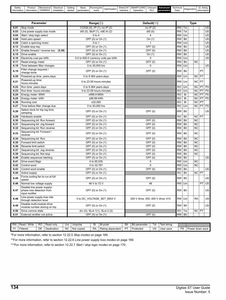
Safety Information
Product information
Mechanical installation
Electrical installation
Getting started
Basic parameters
Running the motor Optimization EtherCAT
interfaceSMARTCARD
OperationOnboard
PLCAdvanced
parametersTechnical
Data Diagnostics UL listing information
*For more information, refer to section 12.22.5 Stop modes on page 169.**For more information, refer to section 12.22.6 Line power supply loss modes on page 169.***For more information, refer to section 12.22.7 Start / stop logic modes on page 170.
Parameter Range( ) Default( ) Type6.01 Stop mode COASt (0), rP (1), no.rP (2) no.rP (2) RW Txt US6.03 Line power supply loss mode diS (0), StoP (1), ridE.th (2) diS (0) RW Txt US6.04 Start / stop logic select 0 to 4 4 RW Uni US6.08 Hold zero speed OFF (0) or On (1) On (1) RW Bit US6.09 Catch a spinning motor 0 to 1 1 RW Uni US6.12 Enable stop key OFF (0) or On (1) OFF (0) RW Bit US6.13 Enable forward / reverse key {0.28} OFF (0) or On (1) OFF (0) RW Bit US6.15 Drive enable OFF (0) or On (1) On (1) RW Bit US6.16 Electricity cost per kWh 0.0 to 600.0 currency units per kWh 0 RW Uni US6.17 Reset energy meter OFF (0) or On (1) OFF (0) RW Bit NC6.18 Time between filter changes 0 to 30,000 hrs 0 RW Uni US
6.19 Filter change required / change done OFF (0) or On (1) OFF (0) RW Bit PT
6.20 Powered-up time: years.days 0 to 9.364 years.days RW Uni NC PT
6.21 Powered-up time: hours.minutes 0 to 23.59 hours.minutes RW Uni NC PT
6.22 Run time: years.days 0 to 9.364 years.days RO Uni NC PT PS6.23 Run time: hours.minutes 0 to 23.59 hours.minutes RO Uni NC PT PS6.24 Energy meter: MWh ±999.9 MWh RO Bi NC PT PS6.25 Energy meter: kWh ±99.99 kWh RO Bi NC PT PS6.26 Running cost ±32,000 RO Bi NC PT6.27 Time before filter change due 0 to 30,000 hrs RO Uni NC PT PS
6.28 Select clock for trip log time sampling OFF (0) or On (1) OFF (0) RW Bit US
6.29 Hardware enable OFF (0) or On (1) RO Bit NC PT6.30 Sequencing bit: Run forward OFF (0) or On (1) OFF (0) RW Bit NC6.31 Sequencing bit: Jog forward OFF (0) or On (1) OFF (0) RW Bit NC6.32 Sequencing bit: Run reverse OFF (0) or On (1) OFF (0) RW Bit NC
6.33 Sequencing bit: Forward / reverse OFF (0) or On (1) OFF (0) RW Bit NC
6.34 Sequencing bit: Run OFF (0) or On (1) OFF (0) RW Bit NC6.35 Forward limit switch OFF (0) or On (1) OFF (0) RW Bit NC6.36 Reverse limit switch OFF (0) or On (1) OFF (0) RW Bit NC6.37 Sequencing bit: Jog reverse OFF (0) or On (1) OFF (0) RW Bit NC6.39 Sequencing bit: Not stop OFF (0) or On (1) OFF (0) RW Bit NC6.40 Enable sequencer latching OFF (0) or On (1) OFF (0) RW Bit US6.41 Drive event flags 0 to 65,535 0 RW Uni NC6.42 Control word 0 to 32,767 0 RW Uni NC6.43 Control word enable OFF (0) or On (1) OFF (0) RW Bit US6.44 Active supply OFF (0) or On (1) RO Bit NC PT
6.45 Force cooling fan to run at full speed OFF (0) or On (1) OFF (0) RW Bit US
6.46 Normal low voltage supply 48 V to 72 V 48 RW Uni PT US
6.47Disable line power supply/phase loss detection from input rectifier
OFF (0) or On (1) OFF (0) RW Bit US
6.48 Line power supply loss ride through detection level 0 to DC_VOLTAGE_SET_MAX V 200 V drive: 205, 400 V drive: 410 RW Uni RA US
6.49 Disable multi-module drive module number storing on trip OFF (0) or On (1) OFF (0) RW Bit US
6.50 Drive comms state drv (0), SLot 1(1), SLot 2 (2) RO Txt NC PT6.51 External rectifier not active OFF (0) or On (1) OFF (0) RW Bit
RW Read / Write RO Read only Uni Unipolar Bi Bi-polar Bit Bit parameter Txt Text stringFI Filtered DE Destination NC Not copied RA Rating dependent PT Protected US User save PS Power down save
134 Digitax ST User Guide Issue Number: 5
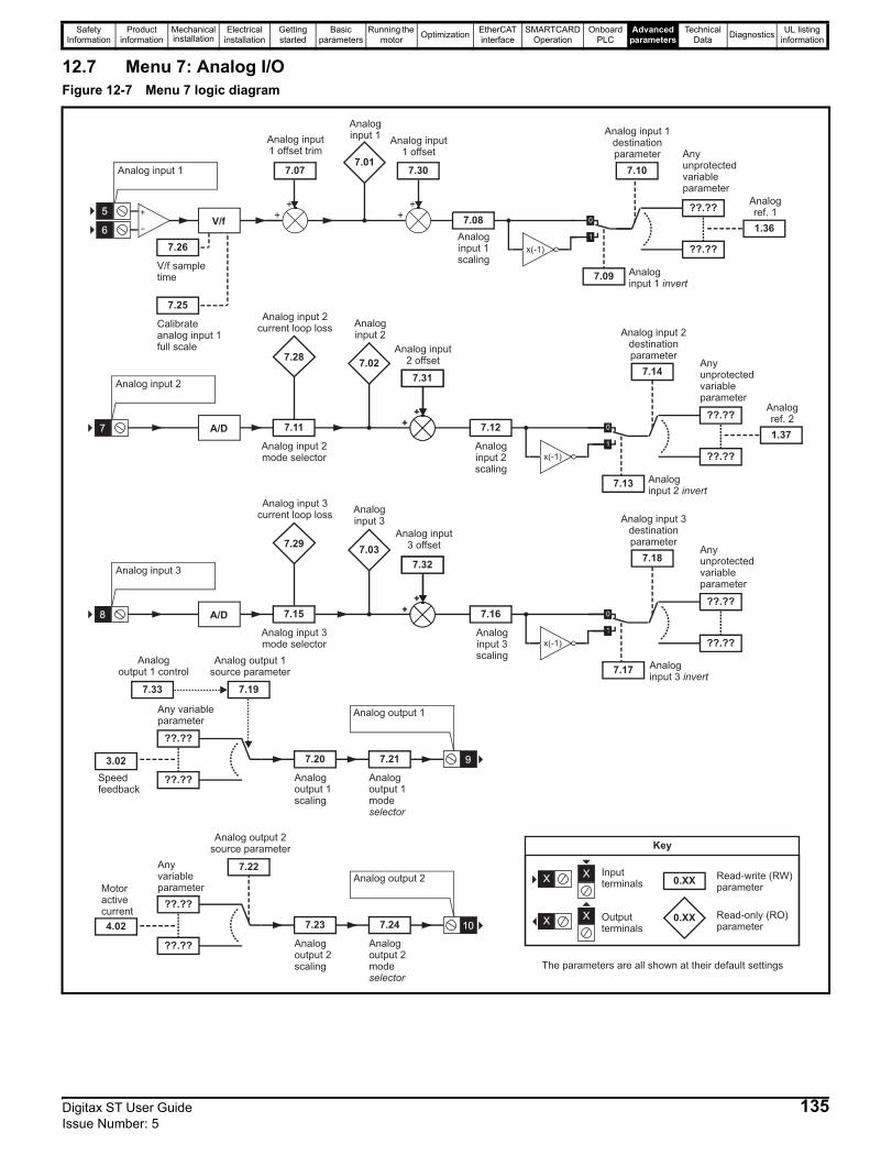
Safety Information
Product information
Mechanical installation
Electrical installation
Getting started
Basic parameters
Running the motor Optimization EtherCAT
interfaceSMARTCARD
OperationOnboard
PLCAdvanced
parametersTechnical
Data Diagnostics UL listing information
12.7 Menu 7: Analog I/OFigure 12-7 Menu 7 logic diagram
Analog input 2
A/D 7.11
Analog input 2mode selector
7.12
Analoginput 2scaling
??.??
Anyunprotectedvariableparameter
??.??
7.14
7.25
Calibrateanalog input 1full scale
7.26
V/f sampletime
7.07
Analog input1 offset trim
7.08
Analoginput 1scaling
??.??
Anyunprotectedvariableparameter
??.??
7.10
Analog input 1destinationparameter
V/f
x(-1)
Analog input 1
Analog input 3
A/D 7.15
Analog input 3mode selector
7.16
Analoginput 3scaling
??.??
Anyunprotectedvariableparameter
??.??
7.18
??.??
Any variableparameter
??.??
7.19
Analog output 1source parameter
7.20
Analogoutput 1scaling
7.21
Analogoutput 1modeselector
Analog output 1
??.??
Anyvariableparameter
??.??
7.22
Analog output 2source parameter
7.23
Analogoutput 2scaling
7.24
Analogoutput 2modeselector
7.09 Analoginput 1 invert
x(-1)
7.01
Analoginput 1
7.02
Analoginput 2
x(-1)
7.17 Analoginput 3 invert
7.13 Analoginput 2 invert
Analog output 2
5
6
7
8
1.36
Analogref. 1
1.37
Analogref. 2
9
10
3.02
Speedfeedback
4.02
Motoractivecurrent
0.XX
0.XX
Key
Read-write (RW)parameter
Read-only (RO)parameter
Inputterminals
Outputterminals
XX
XX
The parameters are all shown at their default settings
++
++
7.30
Analog input1 offset
7.28
Analog input 2current loop loss
++
7.31
++
7.31
Analog input2 offset
++
7.31
++
7.32
Analog input3 offset7.29
Analog input 3current loop loss
7.33
Analogoutput 1 control
Analog input 2destinationparameter
Analog input 3destinationparameter
7.03
Analoginput 3
Digitax ST User Guide 135Issue Number: 5
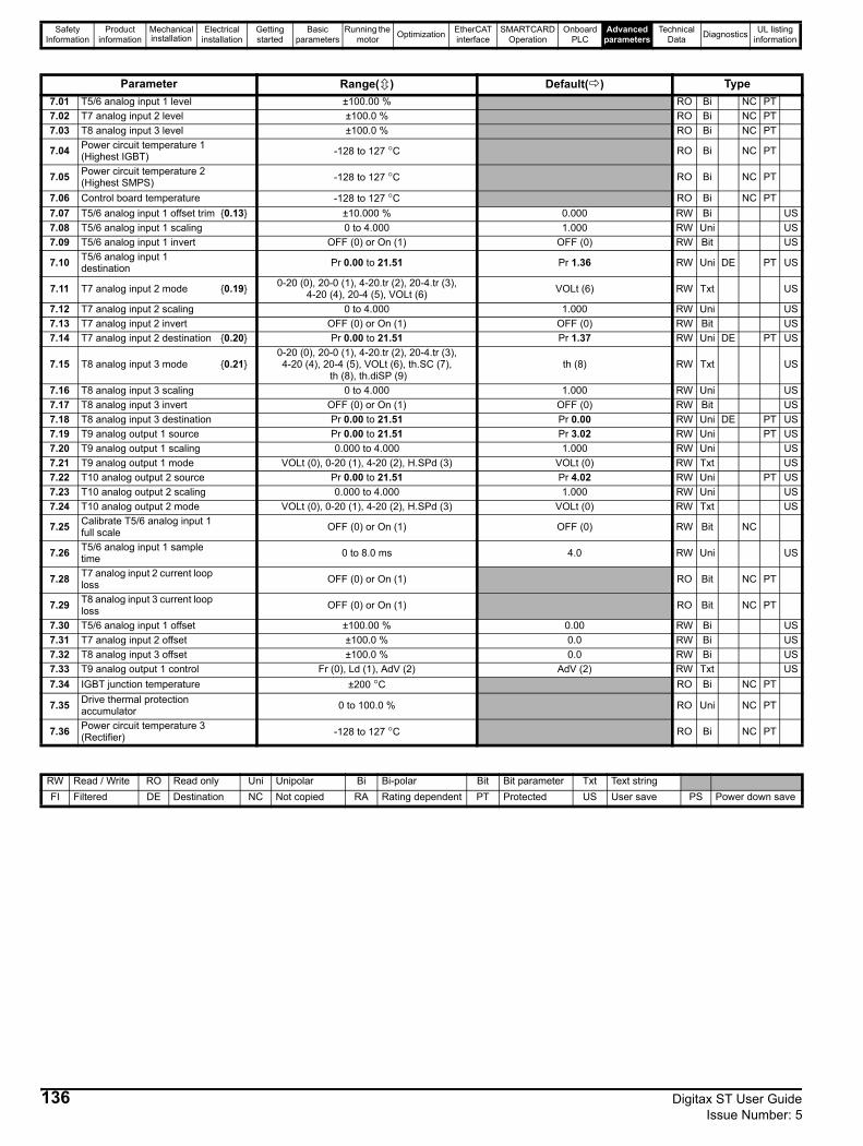
Safety Information
Product information
Mechanical installation
Electrical installation
Getting started
Basic parameters
Running the motor Optimization EtherCAT
interfaceSMARTCARD
OperationOnboard
PLCAdvanced
parametersTechnical
Data Diagnostics UL listing information
Parameter Range( ) Default( ) Type7.01 T5/6 analog input 1 level ±100.00 % RO Bi NC PT7.02 T7 analog input 2 level ±100.0 % RO Bi NC PT7.03 T8 analog input 3 level ±100.0 % RO Bi NC PT
7.04 Power circuit temperature 1 (Highest IGBT) -128 to 127 °C RO Bi NC PT
7.05 Power circuit temperature 2 (Highest SMPS) -128 to 127 °C RO Bi NC PT
7.06 Control board temperature -128 to 127 °C RO Bi NC PT7.07 T5/6 analog input 1 offset trim {0.13} ±10.000 % 0.000 RW Bi US7.08 T5/6 analog input 1 scaling 0 to 4.000 1.000 RW Uni US7.09 T5/6 analog input 1 invert OFF (0) or On (1) OFF (0) RW Bit US
7.10 T5/6 analog input 1 destination Pr 0.00 to 21.51 Pr 1.36 RW Uni DE PT US
7.11 T7 analog input 2 mode {0.19} 0-20 (0), 20-0 (1), 4-20.tr (2), 20-4.tr (3), 4-20 (4), 20-4 (5), VOLt (6) VOLt (6) RW Txt US
7.12 T7 analog input 2 scaling 0 to 4.000 1.000 RW Uni US7.13 T7 analog input 2 invert OFF (0) or On (1) OFF (0) RW Bit US7.14 T7 analog input 2 destination {0.20} Pr 0.00 to 21.51 Pr 1.37 RW Uni DE PT US
7.15 T8 analog input 3 mode {0.21}0-20 (0), 20-0 (1), 4-20.tr (2), 20-4.tr (3), 4-20 (4), 20-4 (5), VOLt (6), th.SC (7),
th (8), th.diSP (9)th (8) RW Txt US
7.16 T8 analog input 3 scaling 0 to 4.000 1.000 RW Uni US7.17 T8 analog input 3 invert OFF (0) or On (1) OFF (0) RW Bit US7.18 T8 analog input 3 destination Pr 0.00 to 21.51 Pr 0.00 RW Uni DE PT US7.19 T9 analog output 1 source Pr 0.00 to 21.51 Pr 3.02 RW Uni PT US7.20 T9 analog output 1 scaling 0.000 to 4.000 1.000 RW Uni US7.21 T9 analog output 1 mode VOLt (0), 0-20 (1), 4-20 (2), H.SPd (3) VOLt (0) RW Txt US7.22 T10 analog output 2 source Pr 0.00 to 21.51 Pr 4.02 RW Uni PT US7.23 T10 analog output 2 scaling 0.000 to 4.000 1.000 RW Uni US7.24 T10 analog output 2 mode VOLt (0), 0-20 (1), 4-20 (2), H.SPd (3) VOLt (0) RW Txt US
7.25 Calibrate T5/6 analog input 1 full scale OFF (0) or On (1) OFF (0) RW Bit NC
7.26 T5/6 analog input 1 sample time 0 to 8.0 ms 4.0 RW Uni US
7.28 T7 analog input 2 current loop loss OFF (0) or On (1) RO Bit NC PT
7.29 T8 analog input 3 current loop loss OFF (0) or On (1) RO Bit NC PT
7.30 T5/6 analog input 1 offset ±100.00 % 0.00 RW Bi US7.31 T7 analog input 2 offset ±100.0 % 0.0 RW Bi US7.32 T8 analog input 3 offset ±100.0 % 0.0 RW Bi US7.33 T9 analog output 1 control Fr (0), Ld (1), AdV (2) AdV (2) RW Txt US7.34 IGBT junction temperature ±200 °C RO Bi NC PT
7.35 Drive thermal protection accumulator 0 to 100.0 % RO Uni NC PT
7.36 Power circuit temperature 3 (Rectifier) -128 to 127 °C RO Bi NC PT
RW Read / Write RO Read only Uni Unipolar Bi Bi-polar Bit Bit parameter Txt Text stringFI Filtered DE Destination NC Not copied RA Rating dependent PT Protected US User save PS Power down save
136 Digitax ST User Guide Issue Number: 5

Safety Information
Product information
Mechanical installation
Electrical installation
Getting started
Basic parameters
Running the motor Optimization EtherCAT
interfaceSMARTCARD
OperationOnboard
PLCAdvanced
parametersTechnical
Data Diagnostics UL listing information
Digitax ST User Guide 137Issue Number: 5
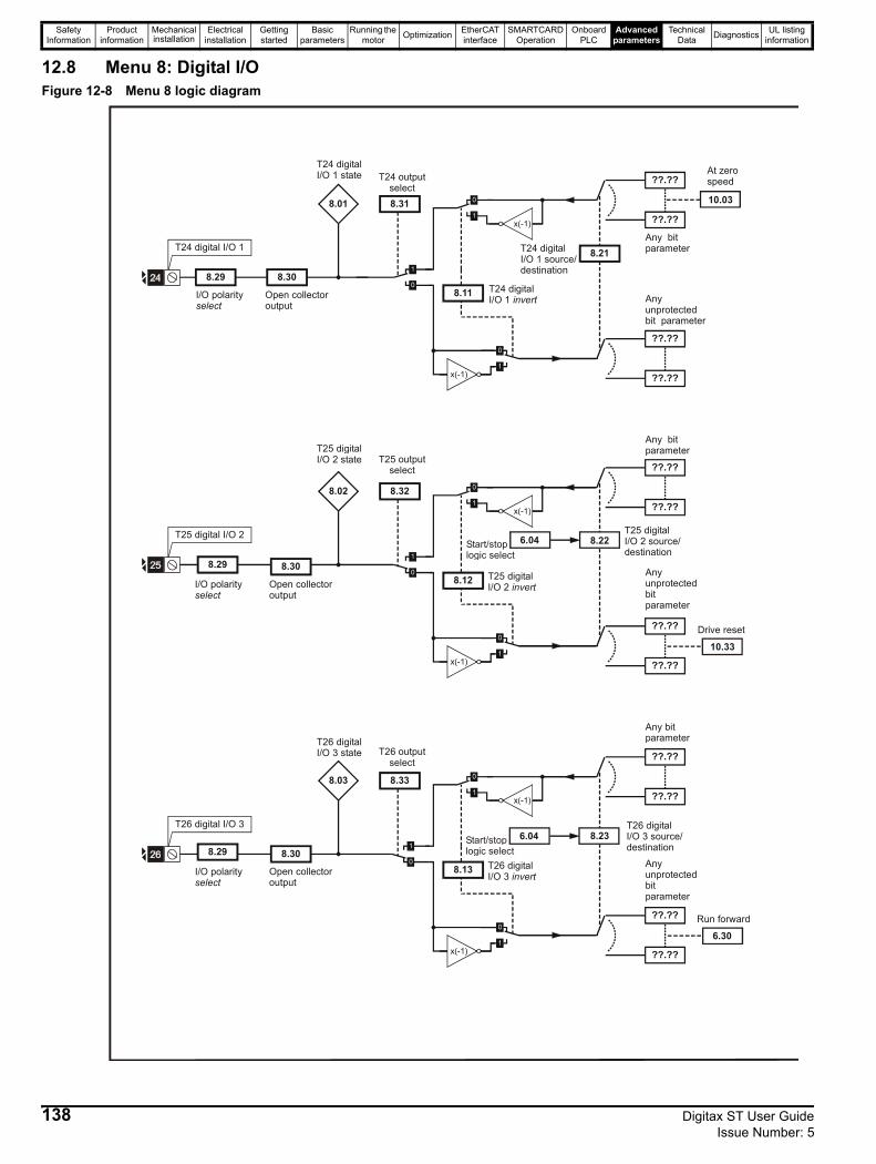
Safety Information
Product information
Mechanical installation
Electrical installation
Getting started
Basic parameters
Running the motor Optimization EtherCAT
interfaceSMARTCARD
OperationOnboard
PLCAdvanced
parametersTechnical
Data Diagnostics UL listing information
12.8 Menu 8: Digital I/OFigure 12-8 Menu 8 logic diagram
T25 digital I/O 2
8.32
??.??
Any unprotected bit parameter
??.??
??.??
??.??
Any bit parameter
8.22
x(-1)
x(-1)
8.12
8.02
T26 digital I/O 3
8.33
??.??
Any unprotected bit parameter
??.??
??.??
Any bit parameter
??.??
8.23
x(-1)
x(-1)
8.13
8.03
8.29
Open collector output
8.30
8.29
Open collector output
8.30
10.33Drive reset
6.30Run forward
I/O polarityselect
I/O polarityselect
T24 digital I/O 1
T24 digital I/O 1 state
8.31
T24 outputselect
??.??
??.??
Any unprotected bit parameter
??.??
??.??
Any bit parameter8.21T24 digital
I/O 1 source/destination
x(-1)
x(-1)
8.11 T24 digital I/O 1 invert
8.01
8.29
I/O polarityselect
Open collector output
8.30
10.03
At zero speed
T25 digital I/O 2 state T25 output
select
T25 digital I/O 2 source/destination
T25 digital I/O 2 invert
T26 digital I/O 3 state T26 output
select
T26 digital I/O 3 source/destination
T26 digital I/O 3 invert
6.04Start/stoplogic select
6.04Start/stoplogic select
138 Digitax ST User Guide Issue Number: 5
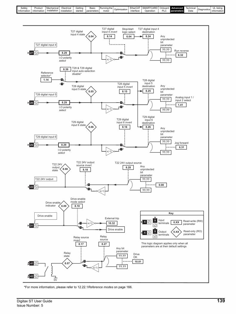
Safety Information
Product information
Mechanical installation
Electrical installation
Getting started
Basic parameters
Running the motor Optimization EtherCAT
interfaceSMARTCARD
OperationOnboard
PLCAdvanced
parametersTechnical
Data Diagnostics UL listing information
T29 digital input 6
??.??
Anyunprotectedbitparameter
??.??
8.26
T29 digitalinput 6
destination
x(-1)
8.16
T29 digitalinput 6 invertT29 digital
input 6 state8.06
8.29296.31
Jog forward
I.O polarityselect
8.27
Relaysource
8.17
Relay sourceinvert
??.??
Any bitparameter
??.??x(-1)
Relaystate
8.0710.01
DriveOK
41
42
0V
0.XX
0.XX
Key
Read-write (RW)parameter
Read-only (RO)parameter
Inputterminals
Outputterminals
XX
XX
This logic diagram applies only when allparameters are at their default settings
8.25
T28 digitalinput 5
destination
??.??
Anyunprotectedbitparameter
??.??x(-1)
8.15
T28 digitalinput 5 invertT28 digital
input 5 state8.05
8.29281.41
Analog input 1 /input 2 select
I.O polarityselect
T28 digital input 5
8.10
Drive enablemode select
Drive enable
10.32
External tripDrive enable
Drive enableindicator 8.09
x(-1)31
T22 24V output
Anyunprotectedbitparameter
??.??
8.28
T22 24V output source
x(-1)
8.18
T22 24V outputsource invertT22 24V
outputstate
8.08
0.00
??.??
22
T27 digital input 4
??.??
Anyunprotectedbitparameter
??.??
8.24
T27 digital input 4destination
x(-1)
8.14
T27 digitalinput 4 invertT27 digital
input 4 state8.04
8.29
I.O polarityselect
276.32
Run reverse
Stop/startlogic select
6.04
1.14
8.39T28 & T29 digitalinput auto-selectiondisable*Reference
selector*
*For more information, please refer to 12.22.1Reference modes on page 166.
Digitax ST User Guide 139Issue Number: 5
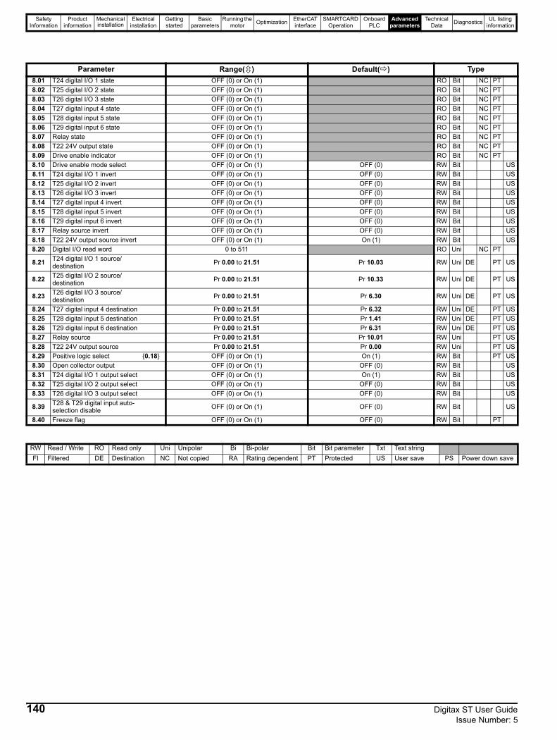
Safety Information
Product information
Mechanical installation
Electrical installation
Getting started
Basic parameters
Running the motor Optimization EtherCAT
interfaceSMARTCARD
OperationOnboard
PLCAdvanced
parametersTechnical
Data Diagnostics UL listing information
Parameter Range( ) Default( ) Type8.01 T24 digital I/O 1 state OFF (0) or On (1) RO Bit NC PT8.02 T25 digital I/O 2 state OFF (0) or On (1) RO Bit NC PT8.03 T26 digital I/O 3 state OFF (0) or On (1) RO Bit NC PT8.04 T27 digital input 4 state OFF (0) or On (1) RO Bit NC PT8.05 T28 digital input 5 state OFF (0) or On (1) RO Bit NC PT8.06 T29 digital input 6 state OFF (0) or On (1) RO Bit NC PT8.07 Relay state OFF (0) or On (1) RO Bit NC PT8.08 T22 24V output state OFF (0) or On (1) RO Bit NC PT8.09 Drive enable indicator OFF (0) or On (1) RO Bit NC PT8.10 Drive enable mode select OFF (0) or On (1) OFF (0) RW Bit US8.11 T24 digital I/O 1 invert OFF (0) or On (1) OFF (0) RW Bit US8.12 T25 digital I/O 2 invert OFF (0) or On (1) OFF (0) RW Bit US8.13 T26 digital I/O 3 invert OFF (0) or On (1) OFF (0) RW Bit US8.14 T27 digital input 4 invert OFF (0) or On (1) OFF (0) RW Bit US8.15 T28 digital input 5 invert OFF (0) or On (1) OFF (0) RW Bit US8.16 T29 digital input 6 invert OFF (0) or On (1) OFF (0) RW Bit US8.17 Relay source invert OFF (0) or On (1) OFF (0) RW Bit US8.18 T22 24V output source invert OFF (0) or On (1) On (1) RW Bit US8.20 Digital I/O read word 0 to 511 RO Uni NC PT
8.21 T24 digital I/O 1 source/destination Pr 0.00 to 21.51 Pr 10.03 RW Uni DE PT US
8.22 T25 digital I/O 2 source/destination Pr 0.00 to 21.51 Pr 10.33 RW Uni DE PT US
8.23 T26 digital I/O 3 source/destination Pr 0.00 to 21.51 Pr 6.30 RW Uni DE PT US
8.24 T27 digital input 4 destination Pr 0.00 to 21.51 Pr 6.32 RW Uni DE PT US8.25 T28 digital input 5 destination Pr 0.00 to 21.51 Pr 1.41 RW Uni DE PT US8.26 T29 digital input 6 destination Pr 0.00 to 21.51 Pr 6.31 RW Uni DE PT US8.27 Relay source Pr 0.00 to 21.51 Pr 10.01 RW Uni PT US8.28 T22 24V output source Pr 0.00 to 21.51 Pr 0.00 RW Uni PT US8.29 Positive logic select {0.18} OFF (0) or On (1) On (1) RW Bit PT US8.30 Open collector output OFF (0) or On (1) OFF (0) RW Bit US8.31 T24 digital I/O 1 output select OFF (0) or On (1) On (1) RW Bit US8.32 T25 digital I/O 2 output select OFF (0) or On (1) OFF (0) RW Bit US8.33 T26 digital I/O 3 output select OFF (0) or On (1) OFF (0) RW Bit US
8.39 T28 & T29 digital input auto-selection disable OFF (0) or On (1) OFF (0) RW Bit US
8.40 Freeze flag OFF (0) or On (1) OFF (0) RW Bit PT
RW Read / Write RO Read only Uni Unipolar Bi Bi-polar Bit Bit parameter Txt Text stringFI Filtered DE Destination NC Not copied RA Rating dependent PT Protected US User save PS Power down save
140 Digitax ST User Guide Issue Number: 5
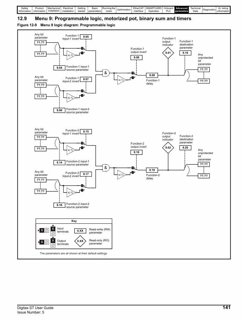
Safety Information
Product information
Mechanical installation
Electrical installation
Getting started
Basic parameters
Running the motor Optimization EtherCAT
interfaceSMARTCARD
OperationOnboard
PLCAdvanced
parametersTechnical
Data Diagnostics UL listing information
12.9 Menu 9: Programmable logic, motorized pot, binary sum and timersFigure 12-9 Menu 9 logic diagram: Programmable logic
??.??
Any unprotected bit parameter
??.??
9.10
Function-1 destination parameter
??.??
Any bit parameter
??.?? x(-1)
9.04 Function-1 input-1 source parameter
9.05Function-1 input-1 invert
??.??
Any bit parameter
??.?? x(-1)
9.06 Function-1 input-2 source parameter
9.07Function-1 input-2 invert
9.08
Function-1 output invert
9.09
Function-1 delay
x(-1)
Function-1 output indicator
9.01
??.??
Any unprotected bit parameter
??.??
9.20
Function-2 destination parameter
??.??
Any bit parameter
??.?? x(-1)
9.14 Function-2 input-1 source parameter
9.15Function-2 input-1 invert
??.??
Any bit parameter
??.?? x(-1)
9.16 Function-2 input-2 source parameter
9.17Function-2 input-2 invert
9.18
Function-2 output invert
9.19
Function-2 delay
x(-1)
Function-2 output indicator
9.02
0.XX
0.XX
Key
Read-write (RW) parameter
Read-only (RO) parameter
Inputterminals
Outputterminals
The parameters are all shown at their default settings
Digitax ST User Guide 141Issue Number: 5
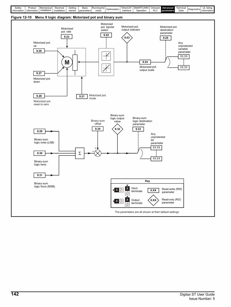
Safety Information
Product information
Mechanical installation
Electrical installation
Getting started
Basic parameters
Running the motor Optimization EtherCAT
interfaceSMARTCARD
OperationOnboard
PLCAdvanced
parametersTechnical
Data Diagnostics UL listing information
Figure 12-10 Menu 9 logic diagram: Motorized pot and binary sum
9.30
Binary-sum logic twos
9.29
Binary-sum logic ones (LSB)
9.31
Binary-sum logic fours (MSB)
9.32
Binary-sumlogic output
value
??.??
Any unprotected bit parameter
??.??
9.33
Binary-sum logic destination parameter
Σ
9.24
Motorized pot. output scale
9.25
Motorized pot. destination parameter
9.23
Motorized pot. rate
??.??
Any unprotected variable parameter
??.??
9.27
Motorized pot. down
9.26
Motorized pot. up
M
9.03
Motorized pot. output indicator
9.22
Motorized pot. bipolar select
9.219.28
Motorized pot.reset to zero
Motorized pot.mode
++
9.34
Binary-sumoffset
0.XX
0.XX
Key
Read-write (RW) parameter
Read-only (RO) parameter
Inputterminals
Outputterminals
The parameters are all shown at their default settings
142 Digitax ST User Guide Issue Number: 5
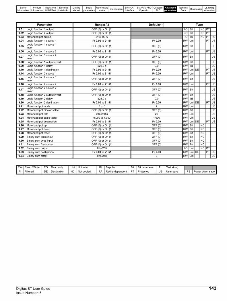
Safety Information
Product information
Mechanical installation
Electrical installation
Getting started
Basic parameters
Running the motor Optimization EtherCAT
interfaceSMARTCARD
OperationOnboard
PLCAdvanced
parametersTechnical
Data Diagnostics UL listing information
Parameter Range( ) Default( ) Type9.01 Logic function 1 output OFF (0) or On (1) RO Bit NC PT9.02 Logic function 2 output OFF (0) or On (1) RO Bit NC PT9.03 Motorized pot output ±100.00 % RO Bi NC PT PS9.04 Logic function 1 source 1 Pr 0.00 to 21.51 Pr 0.00 RW Uni PT US
9.05 Logic function 1 source 1 invert OFF (0) or On (1) OFF (0) RW Bit US
9.06 Logic function 1 source 2 Pr 0.00 to 21.51 Pr 0.00 RW Uni PT US
9.07 Logic function 1 source 2 invert OFF (0) or On (1) OFF (0) RW Bit US
9.08 Logic function 1 output invert OFF (0) or On (1) OFF (0) RW Bit US9.09 Logic function 1 delay ±25.0 s 0.0 RW Bi US9.10 Logic function 1 destination Pr 0.00 to 21.51 Pr 0.00 RW Uni DE PT US9.14 Logic function 2 source 1 Pr 0.00 to 21.51 Pr 0.00 RW Uni PT US
9.15 Logic function 2 source 1 invert OFF (0) or On (1) OFF (0) RW Bit US
9.16 Logic function 2 source 2 Pr 0.00 to 21.51 Pr 0.00 RW Uni PT US
9.17 Logic function 2 source 2 invert OFF (0) or On (1) OFF (0) RW Bit US
9.18 Logic function 2 output invert OFF (0) or On (1) OFF (0) RW Bit US9.19 Logic function 2 delay ±25.0 s 0.0 RW Bi US9.20 Logic function 2 destination Pr 0.00 to 21.51 Pr 0.00 RW Uni DE PT US9.21 Motorized pot mode 0 to 3 2 RW Uni US9.22 Motorized pot bipolar select OFF (0) or On (1) OFF (0) RW Bit US9.23 Motorized pot rate 0 to 250 s 20 RW Uni US9.24 Motorized pot scale factor 0.000 to 4.000 1.000 RW Uni US9.25 Motorized pot destination Pr 0.00 to 21.51 Pr 0.00 RW Uni DE PT US9.26 Motorized pot up OFF (0) or On (1) OFF (0) RW Bit NC9.27 Motorized pot down OFF (0) or On (1) OFF (0) RW Bit NC9.28 Motorized pot reset OFF (0) or On (1) OFF (0) RW Bit NC9.29 Binary sum ones input OFF (0) or On (1) OFF (0) RW Bit NC9.30 Binary sum twos input OFF (0) or On (1) OFF (0) RW Bit NC9.31 Binary sum fours input OFF (0) or On (1) OFF (0) RW Bit NC9.32 Binary sum output 0 to 255 RO Uni NC PT9.33 Binary sum destination Pr 0.00 to 21.51 Pr 0.00 RW Uni DE PT US9.34 Binary sum offset 0 to 248 0 RW Uni US
RW Read / Write RO Read only Uni Unipolar Bi Bi-polar Bit Bit parameter Txt Text stringFI Filtered DE Destination NC Not copied RA Rating dependent PT Protected US User save PS Power down save
Digitax ST User Guide 143Issue Number: 5
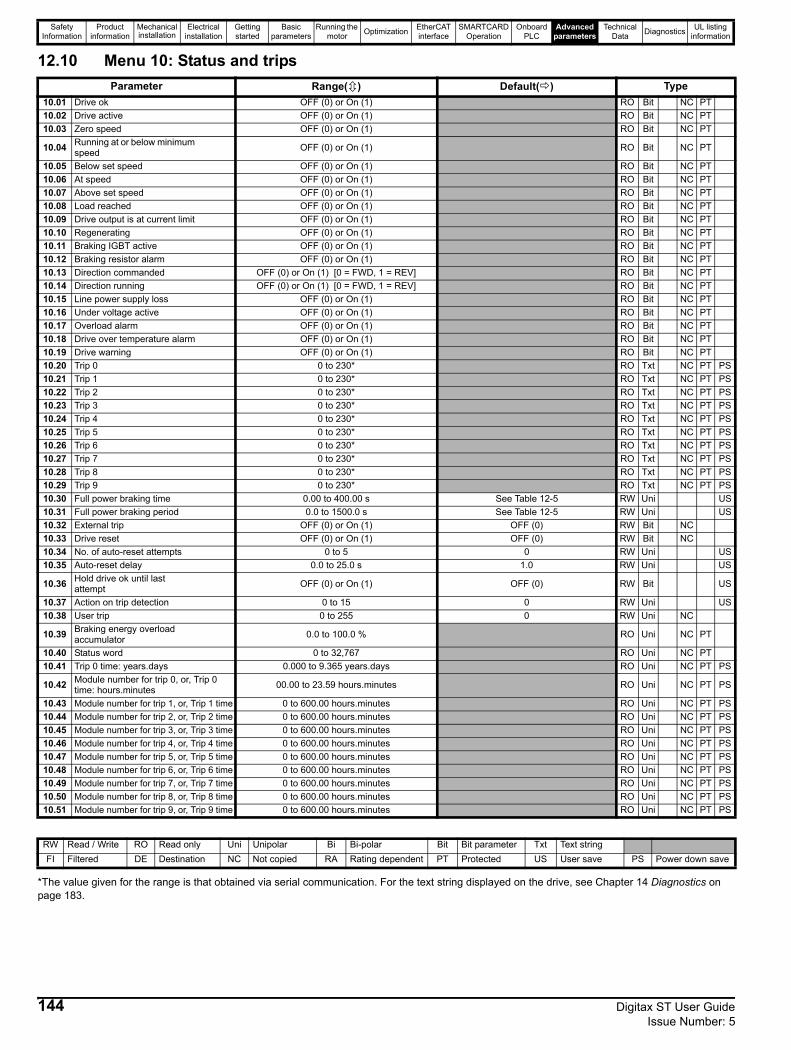
Safety Information
Product information
Mechanical installation
Electrical installation
Getting started
Basic parameters
Running the motor Optimization EtherCAT
interfaceSMARTCARD
OperationOnboard
PLCAdvanced
parametersTechnical
Data Diagnostics UL listing information
12.10 Menu 10: Status and trips
*The value given for the range is that obtained via serial communication. For the text string displayed on the drive, see Chapter 14 Diagnostics on page 183.
Parameter Range( ) Default( ) Type10.01 Drive ok OFF (0) or On (1) RO Bit NC PT10.02 Drive active OFF (0) or On (1) RO Bit NC PT10.03 Zero speed OFF (0) or On (1) RO Bit NC PT
10.04 Running at or below minimum speed OFF (0) or On (1) RO Bit NC PT
10.05 Below set speed OFF (0) or On (1) RO Bit NC PT10.06 At speed OFF (0) or On (1) RO Bit NC PT10.07 Above set speed OFF (0) or On (1) RO Bit NC PT10.08 Load reached OFF (0) or On (1) RO Bit NC PT10.09 Drive output is at current limit OFF (0) or On (1) RO Bit NC PT10.10 Regenerating OFF (0) or On (1) RO Bit NC PT10.11 Braking IGBT active OFF (0) or On (1) RO Bit NC PT10.12 Braking resistor alarm OFF (0) or On (1) RO Bit NC PT10.13 Direction commanded OFF (0) or On (1) [0 = FWD, 1 = REV] RO Bit NC PT10.14 Direction running OFF (0) or On (1) [0 = FWD, 1 = REV] RO Bit NC PT10.15 Line power supply loss OFF (0) or On (1) RO Bit NC PT10.16 Under voltage active OFF (0) or On (1) RO Bit NC PT10.17 Overload alarm OFF (0) or On (1) RO Bit NC PT10.18 Drive over temperature alarm OFF (0) or On (1) RO Bit NC PT10.19 Drive warning OFF (0) or On (1) RO Bit NC PT10.20 Trip 0 0 to 230* RO Txt NC PT PS10.21 Trip 1 0 to 230* RO Txt NC PT PS10.22 Trip 2 0 to 230* RO Txt NC PT PS10.23 Trip 3 0 to 230* RO Txt NC PT PS10.24 Trip 4 0 to 230* RO Txt NC PT PS10.25 Trip 5 0 to 230* RO Txt NC PT PS10.26 Trip 6 0 to 230* RO Txt NC PT PS10.27 Trip 7 0 to 230* RO Txt NC PT PS10.28 Trip 8 0 to 230* RO Txt NC PT PS10.29 Trip 9 0 to 230* RO Txt NC PT PS10.30 Full power braking time 0.00 to 400.00 s See Table 12-5 RW Uni US10.31 Full power braking period 0.0 to 1500.0 s See Table 12-5 RW Uni US10.32 External trip OFF (0) or On (1) OFF (0) RW Bit NC10.33 Drive reset OFF (0) or On (1) OFF (0) RW Bit NC10.34 No. of auto-reset attempts 0 to 5 0 RW Uni US10.35 Auto-reset delay 0.0 to 25.0 s 1.0 RW Uni US
10.36 Hold drive ok until last attempt OFF (0) or On (1) OFF (0) RW Bit US
10.37 Action on trip detection 0 to 15 0 RW Uni US10.38 User trip 0 to 255 0 RW Uni NC
10.39 Braking energy overload accumulator 0.0 to 100.0 % RO Uni NC PT
10.40 Status word 0 to 32,767 RO Uni NC PT10.41 Trip 0 time: years.days 0.000 to 9.365 years.days RO Uni NC PT PS
10.42 Module number for trip 0, or, Trip 0 time: hours.minutes 00.00 to 23.59 hours.minutes RO Uni NC PT PS
10.43 Module number for trip 1, or, Trip 1 time 0 to 600.00 hours.minutes RO Uni NC PT PS10.44 Module number for trip 2, or, Trip 2 time 0 to 600.00 hours.minutes RO Uni NC PT PS10.45 Module number for trip 3, or, Trip 3 time 0 to 600.00 hours.minutes RO Uni NC PT PS10.46 Module number for trip 4, or, Trip 4 time 0 to 600.00 hours.minutes RO Uni NC PT PS10.47 Module number for trip 5, or, Trip 5 time 0 to 600.00 hours.minutes RO Uni NC PT PS10.48 Module number for trip 6, or, Trip 6 time 0 to 600.00 hours.minutes RO Uni NC PT PS10.49 Module number for trip 7, or, Trip 7 time 0 to 600.00 hours.minutes RO Uni NC PT PS10.50 Module number for trip 8, or, Trip 8 time 0 to 600.00 hours.minutes RO Uni NC PT PS10.51 Module number for trip 9, or, Trip 9 time 0 to 600.00 hours.minutes RO Uni NC PT PS
RW Read / Write RO Read only Uni Unipolar Bi Bi-polar Bit Bit parameter Txt Text stringFI Filtered DE Destination NC Not copied RA Rating dependent PT Protected US User save PS Power down save
144 Digitax ST User Guide Issue Number: 5
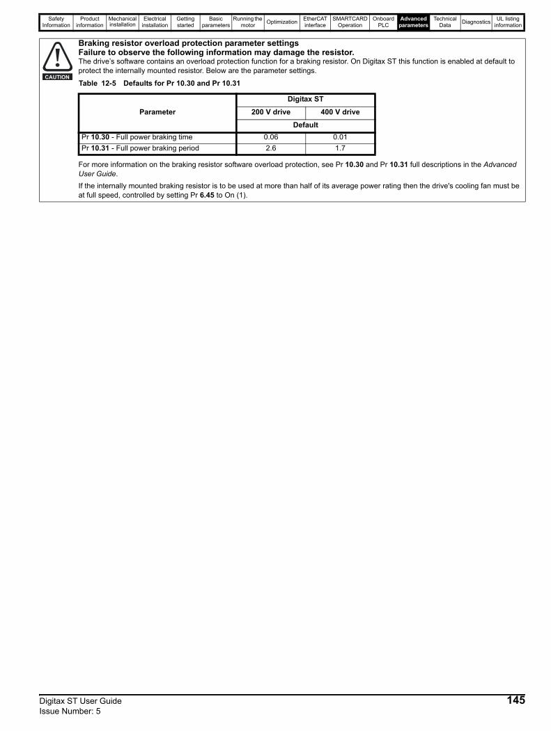
Safety Information
Product information
Mechanical installation
Electrical installation
Getting started
Basic parameters
Running the motor Optimization EtherCAT
interfaceSMARTCARD
OperationOnboard
PLCAdvanced
parametersTechnical
Data Diagnostics UL listing information
Braking resistor overload protection parameter settingsFailure to observe the following information may damage the resistor.The drive’s software contains an overload protection function for a braking resistor. On Digitax ST this function is enabled at default to protect the internally mounted resistor. Below are the parameter settings.
For more information on the braking resistor software overload protection, see Pr 10.30 and Pr 10.31 full descriptions in the Advanced User Guide.If the internally mounted braking resistor is to be used at more than half of its average power rating then the drive's cooling fan must be at full speed, controlled by setting Pr 6.45 to On (1).
CAUTIONTable 12-5 Defaults for Pr 10.30 and Pr 10.31
Parameter
Digitax ST
200 V drive 400 V drive
DefaultPr 10.30 - Full power braking time 0.06 0.01Pr 10.31 - Full power braking period 2.6 1.7
Digitax ST User Guide 145Issue Number: 5
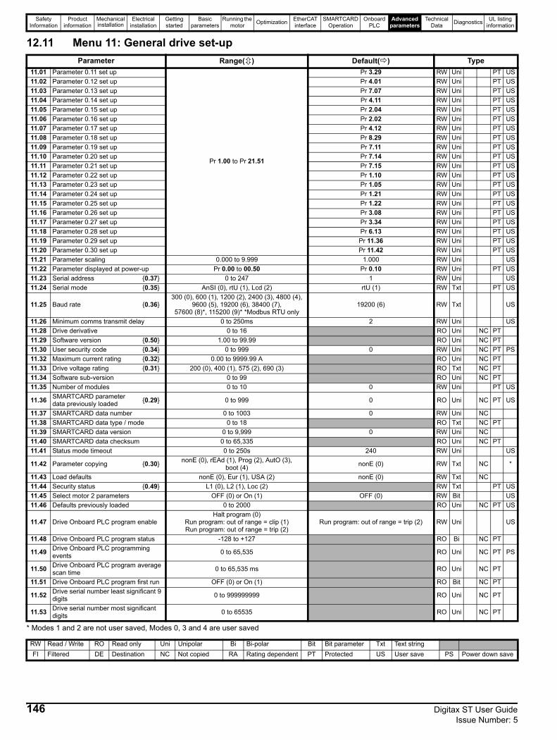
Safety Information
Product information
Mechanical installation
Electrical installation
Getting started
Basic parameters
Running the motor Optimization EtherCAT
interfaceSMARTCARD
OperationOnboard
PLCAdvanced
parametersTechnical
Data Diagnostics UL listing information
12.11 Menu 11: General drive set-up
* Modes 1 and 2 are not user saved, Modes 0, 3 and 4 are user saved
Parameter Range( ) Default( ) Type11.01 Parameter 0.11 set up
Pr 1.00 to Pr 21.51
Pr 3.29 RW Uni PT US11.02 Parameter 0.12 set up Pr 4.01 RW Uni PT US11.03 Parameter 0.13 set up Pr 7.07 RW Uni PT US11.04 Parameter 0.14 set up Pr 4.11 RW Uni PT US11.05 Parameter 0.15 set up Pr 2.04 RW Uni PT US11.06 Parameter 0.16 set up Pr 2.02 RW Uni PT US11.07 Parameter 0.17 set up Pr 4.12 RW Uni PT US11.08 Parameter 0.18 set up Pr 8.29 RW Uni PT US11.09 Parameter 0.19 set up Pr 7.11 RW Uni PT US11.10 Parameter 0.20 set up Pr 7.14 RW Uni PT US11.11 Parameter 0.21 set up Pr 7.15 RW Uni PT US11.12 Parameter 0.22 set up Pr 1.10 RW Uni PT US11.13 Parameter 0.23 set up Pr 1.05 RW Uni PT US11.14 Parameter 0.24 set up Pr 1.21 RW Uni PT US11.15 Parameter 0.25 set up Pr 1.22 RW Uni PT US11.16 Parameter 0.26 set up Pr 3.08 RW Uni PT US11.17 Parameter 0.27 set up Pr 3.34 RW Uni PT US11.18 Parameter 0.28 set up Pr 6.13 RW Uni PT US11.19 Parameter 0.29 set up Pr 11.36 RW Uni PT US11.20 Parameter 0.30 set up Pr 11.42 RW Uni PT US11.21 Parameter scaling 0.000 to 9.999 1.000 RW Uni US11.22 Parameter displayed at power-up Pr 0.00 to 00.50 Pr 0.10 RW Uni PT US11.23 Serial address {0.37} 0 to 247 1 RW Uni US11.24 Serial mode {0.35} AnSI (0), rtU (1), Lcd (2) rtU (1) RW Txt PT US
11.25 Baud rate {0.36}300 (0), 600 (1), 1200 (2), 2400 (3), 4800 (4),
9600 (5), 19200 (6), 38400 (7), 57600 (8)*, 115200 (9)* *Modbus RTU only
19200 (6) RW Txt US
11.26 Minimum comms transmit delay 0 to 250ms 2 RW Uni US11.28 Drive derivative 0 to 16 RO Uni NC PT11.29 Software version {0.50} 1.00 to 99.99 RO Uni NC PT11.30 User security code {0.34} 0 to 999 0 RW Uni NC PT PS11.32 Maximum current rating {0.32} 0.00 to 9999.99 A RO Uni NC PT11.33 Drive voltage rating {0.31} 200 (0), 400 (1), 575 (2), 690 (3) RO Txt NC PT11.34 Software sub-version 0 to 99 RO Uni NC PT11.35 Number of modules 0 to 10 0 RW Uni PT US
11.36 SMARTCARD parameter data previously loaded {0.29} 0 to 999 0 RO Uni NC PT US
11.37 SMARTCARD data number 0 to 1003 0 RW Uni NC11.38 SMARTCARD data type / mode 0 to 18 RO Txt NC PT11.39 SMARTCARD data version 0 to 9,999 0 RW Uni NC11.40 SMARTCARD data checksum 0 to 65,335 RO Uni NC PT11.41 Status mode timeout 0 to 250s 240 RW Uni US
11.42 Parameter copying {0.30} nonE (0), rEAd (1), Prog (2), AutO (3), boot (4) nonE (0) RW Txt NC *
11.43 Load defaults nonE (0), Eur (1), USA (2) nonE (0) RW Txt NC11.44 Security status {0.49} L1 (0), L2 (1), Loc (2) RW Txt PT US11.45 Select motor 2 parameters OFF (0) or On (1) OFF (0) RW Bit US11.46 Defaults previously loaded 0 to 2000 RO Uni NC PT US
11.47 Drive Onboard PLC program enableHalt program (0)
Run program: out of range = clip (1)Run program: out of range = trip (2)
Run program: out of range = trip (2) RW Uni US
11.48 Drive Onboard PLC program status -128 to +127 RO Bi NC PT
11.49 Drive Onboard PLC programming events 0 to 65,535 RO Uni NC PT PS
11.50 Drive Onboard PLC program average scan time 0 to 65,535 ms RO Uni NC PT
11.51 Drive Onboard PLC program first run OFF (0) or On (1) RO Bit NC PT
11.52 Drive serial number least significant 9 digits 0 to 999999999 RO Uni NC PT
11.53 Drive serial number most significant digits 0 to 65535 RO Uni NC PT
RW Read / Write RO Read only Uni Unipolar Bi Bi-polar Bit Bit parameter Txt Text stringFI Filtered DE Destination NC Not copied RA Rating dependent PT Protected US User save PS Power down save
146 Digitax ST User Guide Issue Number: 5
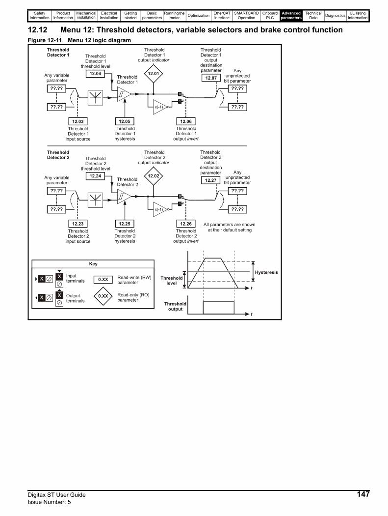
Safety Information
Product information
Mechanical installation
Electrical installation
Getting started
Basic parameters
Running the motor Optimization EtherCAT
interfaceSMARTCARD
OperationOnboard
PLCAdvanced
parametersTechnical
Data Diagnostics UL listing information
12.12 Menu 12: Threshold detectors, variable selectors and brake control functionFigure 12-11 Menu 12 logic diagram
??.??
Any variable parameter
??.??
12.03Threshold Detector 1
input source
12.04
Threshold Detector 1
threshold level
Threshold Detector 1
Threshold Detector 1
x(-1)
12.06ThresholdDetector 1
output invert
12.01
Threshold Detector 1
output indicator
12.05Threshold Detector 1 hysteresis
??.??
Any unprotected
bit parameter
??.??
12.07
ThresholdDetector
outputdestinationparameter
1
??.??
Any variable parameter
??.??
12.23Threshold Detector 2
input source
12.24
Threshold Detector 2
threshold level
Threshold Detector 2
Threshold Detector 2
x(-1)
12.26ThresholdDetector 2
output invert
12.02
Threshold Detector 2
output indicator
12.25Threshold Detector 2 hysteresis
??.??
??.??
12.27
ThresholdDetector
outputdestinationparameter
2
All parameters are shown at their default setting
0.XX
0.XX
Key
Read-write (RW) parameter
Read-only (RO) parameter
Inputterminals
Outputterminals
HysteresisThreshold
level
Thresholdoutput
t
t
Any unprotected
bit parameter
Digitax ST User Guide 147Issue Number: 5
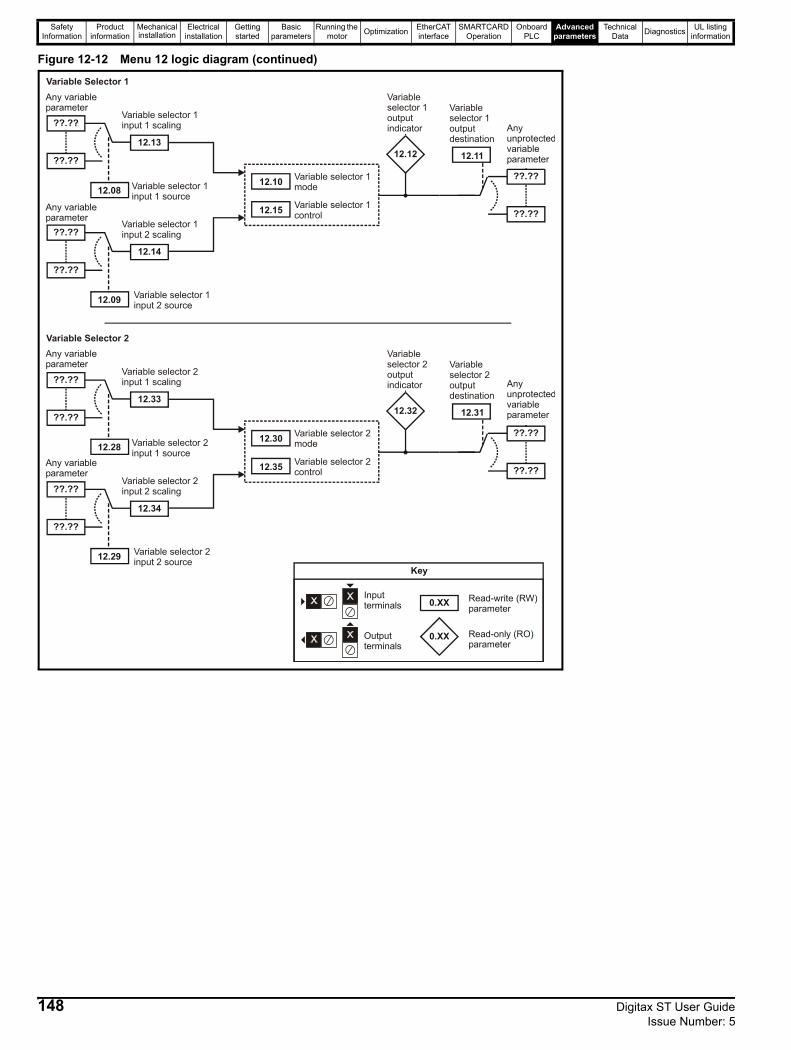
Safety Information
Product information
Mechanical installation
Electrical installation
Getting started
Basic parameters
Running the motor Optimization EtherCAT
interfaceSMARTCARD
OperationOnboard
PLCAdvanced
parametersTechnical
Data Diagnostics UL listing information
Figure 12-12 Menu 12 logic diagram (continued)
12.32
??.??
??.??
12.31
Variable Selector 2
Variable selector 2mode
Variable selector 2control
12.30
12.35
??.??
??.??
12.28
12.33
Variable selector 2input 1 source
Variable selector 2input 1 scaling
??.??
??.??
12.29
12.34
Variable selector 2input 2 source
Variable selector 2input 2 scaling
Variable selector 2output indicator
Variable selector 2output destination
12.12
??.??
??.??
12.11
Variable Selector 1
Variable selector 1mode
Variable selector 1control
12.10
12.15
??.??
Any variableparameter
??.??
12.08
12.13
Variable selector 1input 1 source
Variable selector 1input 1 scaling
??.??
??.??
12.09
12.14
Variable selector 1input 2 source
Variable selector 1input 2 scaling
Variable selector 1output indicator
Variable selector 1output destination
Any variableparameter
Any variableparameter
Any variableparameter
Any unprotectedvariableparameter
Any unprotectedvariableparameter
0.XX
0.XX
Key
Read-write (RW) parameter
Read-only (RO) parameter
Inputterminals
Outputterminals
148 Digitax ST User Guide Issue Number: 5
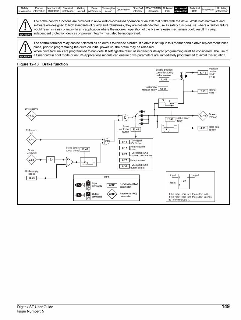
Safety Information
Product information
Mechanical installation
Electrical installation
Getting started
Basic parameters
Running the motor Optimization EtherCAT
interfaceSMARTCARD
OperationOnboard
PLCAdvanced
parametersTechnical
Data Diagnostics UL listing information
Figure 12-13 Brake function
The brake control functions are provided to allow well co-ordinated operation of an external brake with the drive. While both hardware and software are designed to high standards of quality and robustness, they are not intended for use as safety functions, i.e. where a fault or failure would result in a risk of injury. In any application where the incorrect operation of the brake release mechanism could result in injury, independent protection devices of proven integrity must also be incorporated.WARNING
The control terminal relay can be selected as an output to release a brake. If a drive is set up in this manner and a drive replacement takes place, prior to programming the drive on initial power up, the brake may be released.When drive terminals are programmed to non default settings the result of incorrect or delayed programming must be considered. The use of a Smartcard in boot mode or an SM-Applications module can ensure drive parameters are immediately programmed to avoid this situation.WARNING
3.02
Speedfeedback
Brake applyspeed
12.45
+_
Post-brake release delay
0.XX
0.XX
Key
Read-write (RW) parameter
Read-only (RO) parameter
Inputterminals
Outputterminals
LAT
input
reset
output
If the reset input is 1, the output is 0.If the reset input is 0, the output latches at 1 if the input is 1.
i
r
o
1.11
Referenceon
OR
Brake applyspeed delay 12.46
10.02
Drive active
12.47
12.40 Brakerelease
2.03
6.08 Hold zerospeed
Ramphold
Brakecontroller
enable12.41
8.12
8.17
8.22
8.27
8.32
T25 digitalI/O 2 invertRelay sourceinvertT25 digital I/O 2source / destination
Relay source
T25 digital I/O 2 output select
12.48 Brake applydelay
Enable positioncontroller duringbrake release
12.49
13.10Positioncontrolmode( = 1)
Digitax ST User Guide 149Issue Number: 5
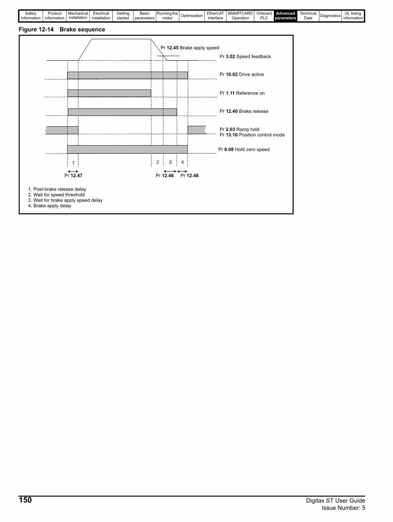
Safety Information
Product information
Mechanical installation
Electrical installation
Getting started
Basic parameters
Running the motor Optimization EtherCAT
interfaceSMARTCARD
OperationOnboard
PLCAdvanced
parametersTechnical
Data Diagnostics UL listing information
Figure 12-14 Brake sequence
1 2 43
Pr Speed feedback3.02
Pr Reference on1.11
Pr Brake release12.40
Pr Ramp hold2.03Pr Position control mode13.10
Pr Drive active10.02
1. Post-brake release delay2. Wait for speed threshold3. Wait for brake apply speed delay4. Brake apply delay
Pr Hold zero speed6.08
Pr Brake apply speed12.45
Pr 12.47 Pr 12.46 Pr 12.48
150 Digitax ST User Guide Issue Number: 5
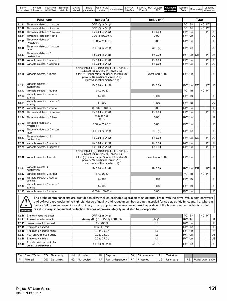
Safety Information
Product information
Mechanical installation
Electrical installation
Getting started
Basic parameters
Running the motor Optimization EtherCAT
interfaceSMARTCARD
OperationOnboard
PLCAdvanced
parametersTechnical
Data Diagnostics UL listing information
Parameter Range( ) Default( ) Type12.01 Threshold detector 1 output OFF (0) or On (1) RO Bit NC PT12.02 Threshold detector 2 output OFF (0) or On (1) RO Bit NC PT12.03 Threshold detector 1 source Pr 0.00 to 21.51 Pr 0.00 RW Uni PT US12.04 Threshold detector 1 level 0.00 to 100.00 % 0.00 RW Uni US
12.05 Threshold detector 1 hysteresis 0.00 to 25.00 % 0.00 RW Uni US
12.06 Threshold detector 1 output invert OFF (0) or On (1) OFF (0) RW Bit US
12.07 Threshold detector 1 destination Pr 0.00 to 21.51 Pr 0.00 RW Uni DE PT US
12.08 Variable selector 1 source 1 Pr 0.00 to 21.51 Pr 0.00 RW Uni PT US12.09 Variable selector 1 source 2 Pr 0.00 to 21.51 Pr 0.00 RW Uni PT US
12.10 Variable selector 1 mode
Select input 1 (0), select input 2 (1), add (2), subtract (3), multiply (4), divide (5),
filter (6), linear ramp (7), absolute value (8), powers (9), sectional control (10),
external rectifier monitor (11)
Select input 1 (0) RW Uni US
12.11 Variable selector 1 destination Pr 0.00 to 21.51 Pr 0.00 RW Uni DE PT US
12.12 Variable selector 1 output ±100.00 % RO Bi NC PT
12.13 Variable selector 1 source 1 scaling ±4.000 1.000 RW Bi US
12.14 Variable selector 1 source 2 scaling ±4.000 1.000 RW Bi US
12.15 Variable selector 1 control 0.00 to 100.00 s 0.00 RW Uni US12.23 Threshold detector 2 source Pr 0.00 to 21.51 Pr 0.00 RW Uni PT US
12.24 Threshold detector 2 level 0.00 to 100.00 % 0.00 RW Uni US
12.25 Threshold detector 2 hysteresis 0.00 to 25.00 % 0.00 RW Uni US
12.26 Threshold detector 2 output invert OFF (0) or On (1) OFF (0) RW Bit US
12.27 Threshold detector 2 destination Pr 0.00 to 21.51 Pr 0.00 RW Uni DE PT US
12.28 Variable selector 2 source 1 Pr 0.00 to 21.51 Pr 0.00 RW Uni PT US12.29 Variable selector 2 source 2 Pr 0.00 to 21.51 Pr 0.00 RW Uni PT US
12.30 Variable selector 2 mode
Select input 1 (0), select input 2 (1), add (2), subtract (3), multiply (4), divide (5),
filter (6), linear ramp (7), absolute value (8), powers (9), sectional control (10),
external rectifier monitor (11)
Select input 1 (0) RW Uni US
12.31 Variable selector 2 destination Pr 0.00 to 21.51 Pr 0.00 RW Uni DE PT US
12.32 Variable selector 2 output ±100.00 % RO Bi NC PT
12.33 Variable selector 2 source 1 scaling ±4.000 1.000 RW Bi US
12.34 Variable selector 2 source 2 scaling ±4.000 1.000 RW Bi US
12.35 Variable selector 2 control 0.00 to 100.00 s 0.00 RW Uni US
12.40 Brake release indicator OFF (0) or On (1) RO Bit NC PT12.41 Brake controller enable dis (0), rEL (1), d IO (2), USEr (3) dis (0) RW Txt US12.43 Lower current threshold 0 to 200 % 10 RW Uni US12.45 Brake apply speed 0 to 200 rpm 5 RW Bit US12.46 Brake apply speed delay 0.0 to 25.0 s 1.0 RW Uni US12.47 Post brake release delay 0.0 to 25.0 s 1.0 RW Uni US12.48 Brake apply delay 0.0 to 25.0 s 1.0 RW Uni US
12.49 Enable position controller during brake release OFF (0) or On (1) OFF (0) RW Bit US
The brake control functions are provided to allow well co-ordinated operation of an external brake with the drive. While both hardware and software are designed to high standards of quality and robustness, they are not intended for use as safety functions, i.e. where a fault or failure would result in a risk of injury. In any application where the incorrect operation of the brake release mechanism could result in injury, independent protection devices of proven integrity must also be incorporated.WARNING
RW Read / Write RO Read only Uni Unipolar Bi Bi-polar Bit Bit parameter Txt Text stringFI Filtered DE Destination NC Not copied RA Rating dependent PT Protected US User save PS Power down save
Digitax ST User Guide 151Issue Number: 5
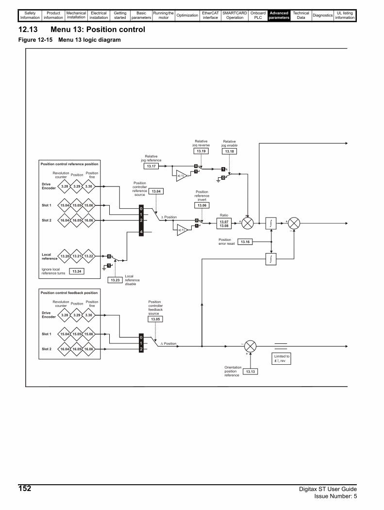
Safety Information
Product information
Mechanical installation
Electrical installation
Getting started
Basic parameters
Running the motor Optimization EtherCAT
interfaceSMARTCARD
OperationOnboard
PLCAdvanced
parametersTechnical
Data Diagnostics UL listing information
12.13 Menu 13: Position controlFigure 12-15 Menu 13 logic diagram
3.28 3.29 3.30
Revolutioncounter Position Position
fine
DriveEncoder
15.04 15.05 15.06Slot 1
16.04 16.05 16.06Slot 2
13.20 13.21 13.22Localreference
13.23Localreference disable
13.04
Position controllerreference
source
x(-1)
13.06
Positionreference
invert
13.0713.08
Ratio
++
x(-1)
13.19
Relativejog reverse
13.18
Relativejog enable
13.17
Relativejog reference
Δ Position
13.16Positionerror reset
13.05
Positioncontrollerfeedbacksource
+
_
13.13Orientationpositionreference
+
_
Position control reference position
3.28 3.29 3.30
Revolutioncounter Position Position
fine
DriveEncoder
15.04 15.05 15.06Slot 1
16.04 16.05 16.06Slot 2
Position control feedback position
13.24Ignore localreference turns
∫
∫
Δ Position
Limited to/ rev1
2±
152 Digitax ST User Guide Issue Number: 5
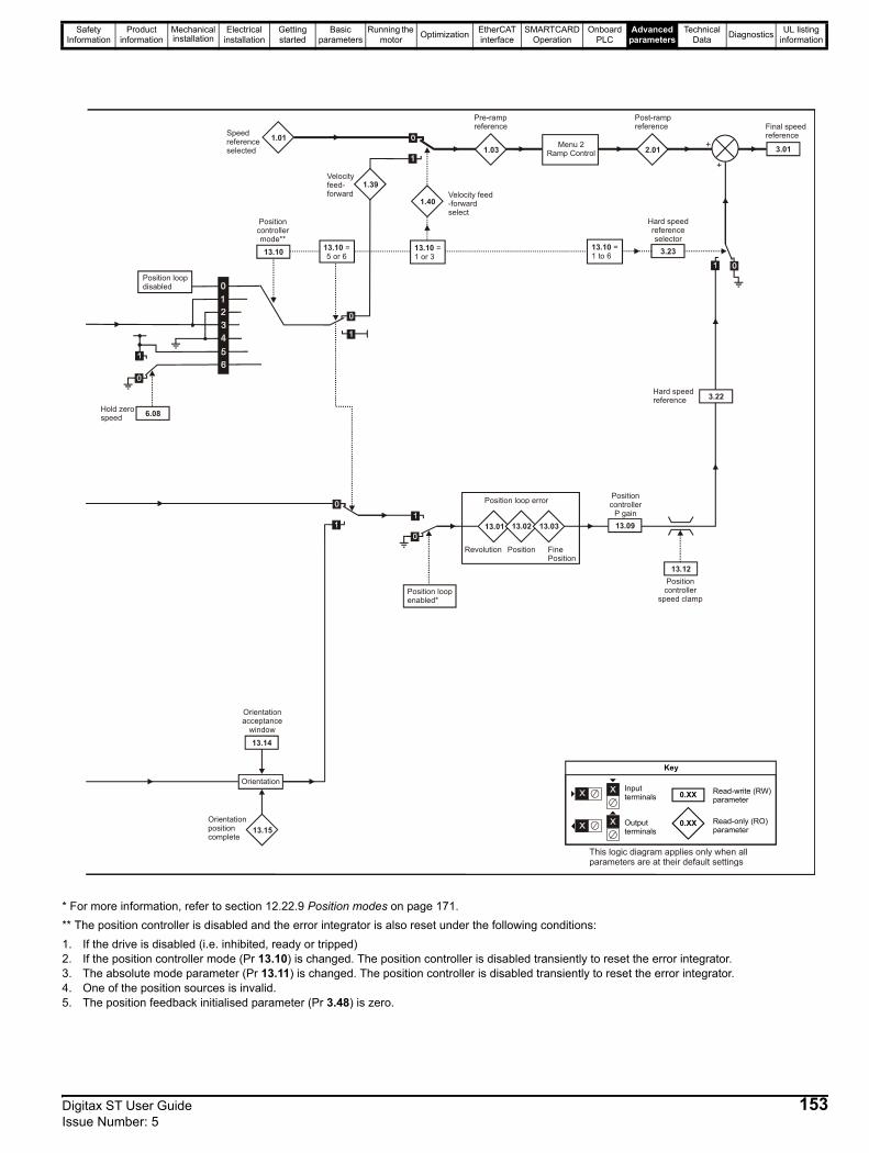
Safety Information
Product information
Mechanical installation
Electrical installation
Getting started
Basic parameters
Running the motor Optimization EtherCAT
interfaceSMARTCARD
OperationOnboard
PLCAdvanced
parametersTechnical
Data Diagnostics UL listing information
* For more information, refer to section 12.22.9 Position modes on page 171.** The position controller is disabled and the error integrator is also reset under the following conditions:1. If the drive is disabled (i.e. inhibited, ready or tripped)2. If the position controller mode (Pr 13.10) is changed. The position controller is disabled transiently to reset the error integrator.3. The absolute mode parameter (Pr 13.11) is changed. The position controller is disabled transiently to reset the error integrator.4. One of the position sources is invalid.5. The position feedback initialised parameter (Pr 3.48) is zero.
0.XX
0.XX
Key
Read-write (RW) parameter
Read-only (RO) parameter
Inputterminals
Outputterminals
Orientation
13.14
13.15
Orientationacceptance
window
Orientationpositioncomplete
13.01 13.02 13.03
Position loop error
Position loopenabled*
6.08Hold zerospeed
13.10
Positioncontrollermode**
1.01
1.39
Speedreference selected
Velocityfeed-forward
1.40Velocity feed-forwardselect
1.03
Pre-rampreference
Menu 2Ramp Control 2.01
Post-rampreference
+
13.09
Position controller
P gain
13.12Position
controllerspeed clamp
3.22Hard speedreference
+
3.23
Hard speedreferenceselector
3.01
Final speedreference
Position loopdisabled
Revolution Position FinePosition
13.10 = 5 or 6
13.10 = 1 or 3
13.10 =1 to 6
This logic diagram applies only when allparameters are at their default settings
Digitax ST User Guide 153Issue Number: 5
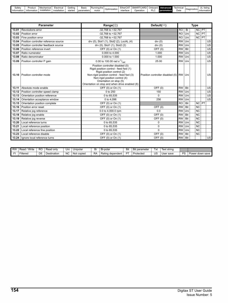
Safety Information
Product information
Mechanical installation
Electrical installation
Getting started
Basic parameters
Running the motor Optimization EtherCAT
interfaceSMARTCARD
OperationOnboard
PLCAdvanced
parametersTechnical
Data Diagnostics UL listing information
Parameter Range( ) Default( ) Type13.01 Revolutions error -32,768 to +32,767 RO Bi NC PT13.02 Position error -32,768 to +32,767 RO Uni NC PT13.03 Fine position error -32,768 to +32,767 RO Uni NC PT13.04 Position controller reference source drv (0), Slot1 (1), Slot2 (2), LocAL (4) drv (0) RW Uni US13.05 Position controller feedback source drv (0), Slot1 (1), Slot2 (2) drv (0) RW Uni US13.06 Position reference invert OFF (0) or On (1) OFF (0) RW Bit US13.07 Ratio numerator 0.000 to 4.000 1.000 RW Uni US13.08 Ratio denominator 0.000 to 1.000 1.000 RW Uni US13.09 Position controller P gain 0.00 to 100.00 rad s-1/rad 25.00 RW Uni US
13.10 Position controller mode
Position controller disabled (0)Rigid position control - feed fwd (1)
Rigid position control (2)Non-rigid position control - feed fwd (3)
Non-rigid position control (4)Orientation on stop (5)
Orientation on stop and when drive enabled (6)
Position controller disabled (0) RW Uni US
13.11 Absolute mode enable OFF (0) or On (1) OFF (0) RW Bit US13.12 Position controller speed clamp 0 to 250 150 RW Uni US13.13 Orientation position reference 0 to 65,535 0 RW Uni US13.14 Orientation acceptance window 0 to 4,096 256 RW Uni US13.15 Orientation position complete OFF (0) or On (1) RO Bit NC PT13.16 Position error reset OFF (0) or On (1) OFF (0) RW Bit NC13.17 Relative jog reference 0.0 to 4,000.0 rpm 0.0 RW Uni NC13.18 Relative jog enable OFF (0) or On (1) OFF (0) RW Bit NC13.19 Relative jog reverse OFF (0) or On (1) OFF (0) RW Bit NC13.20 Local reference turns 0 to 65,535 0 RW Uni NC13.21 Local reference position 0 to 65,535 0 RW Uni NC13.22 Local reference fine position 0 to 65,535 0 RW Uni NC13.23 Local reference disable OFF (0) or On (1) OFF (0) RW Bit NC13.24 Ignore local reference turns OFF (0) or On (1) OFF (0) RW Bit US
RW Read / Write RO Read only Uni Unipolar Bi Bi-polar Bit Bit parameter Txt Text stringFI Filtered DE Destination NC Not copied RA Rating dependent PT Protected US User save PS Power down save
154 Digitax ST User Guide Issue Number: 5

Safety Information
Product information
Mechanical installation
Electrical installation
Getting started
Basic parameters
Running the motor Optimization EtherCAT
interfaceSMARTCARD
OperationOnboard
PLCAdvanced
parametersTechnical
Data Diagnostics UL listing information
Digitax ST User Guide 155Issue Number: 5
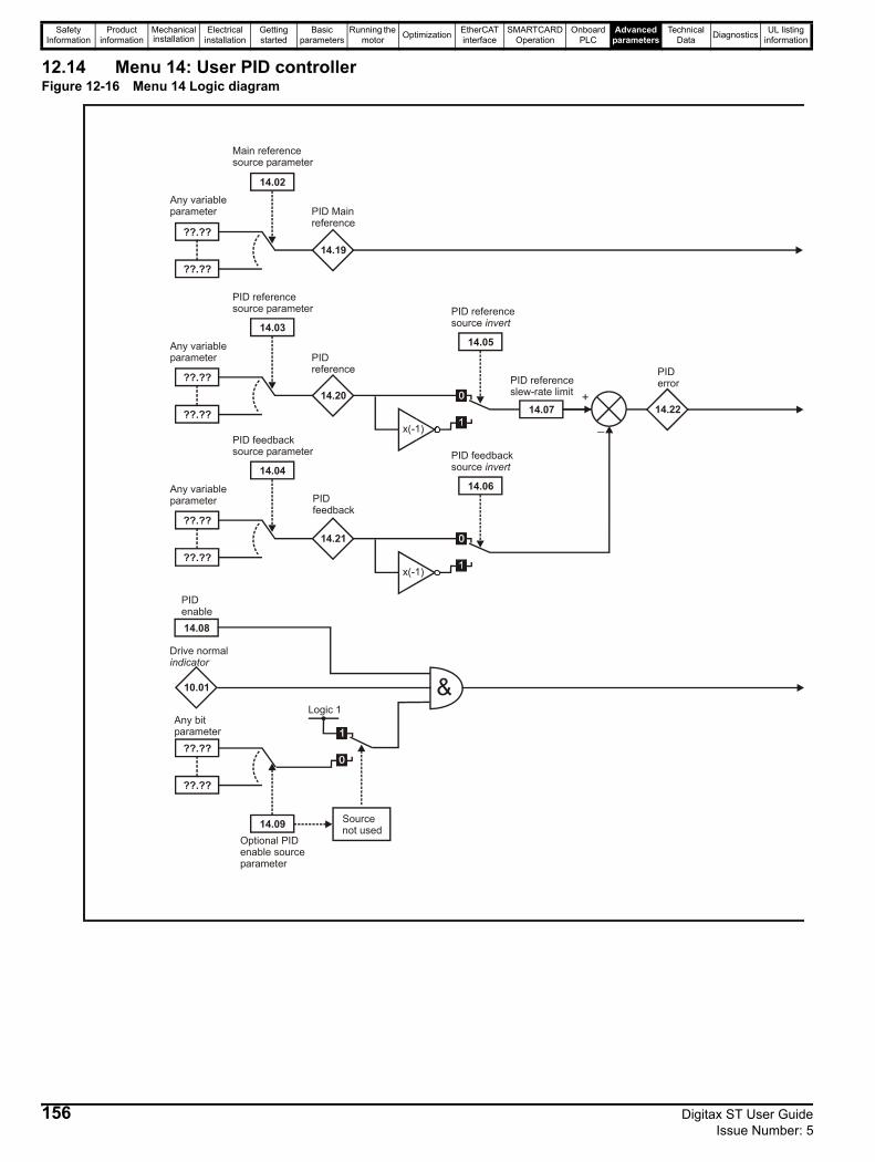
Safety Information
Product information
Mechanical installation
Electrical installation
Getting started
Basic parameters
Running the motor Optimization EtherCAT
interfaceSMARTCARD
OperationOnboard
PLCAdvanced
parametersTechnical
Data Diagnostics UL listing information
12.14 Menu 14: User PID controllerFigure 12-16 Menu 14 Logic diagram
??.??
??.??
14.19
14.02
??.??
??.??
14.20
14.03
??.??
??.??
14.21
14.04
14.07+
_14.22
??.??
??.??
14.09
10.01
14.08
&
Any variableparameter
Any variableparameter
Any variableparameter
Any bitparameter
Main referencesource parameter
PID Main reference
PID referencesource parameter
PID reference
PID feedbacksource parameter
PID feedback
PID enable
Drive normal indicator
Optional PID enable source parameter
x(-1)
x(-1)
PID referenceslew-rate limit
PID error
Source not used
Logic 1
14.05
PID referencesource invert
14.06
PID feedbacksource invert
156 Digitax ST User Guide Issue Number: 5
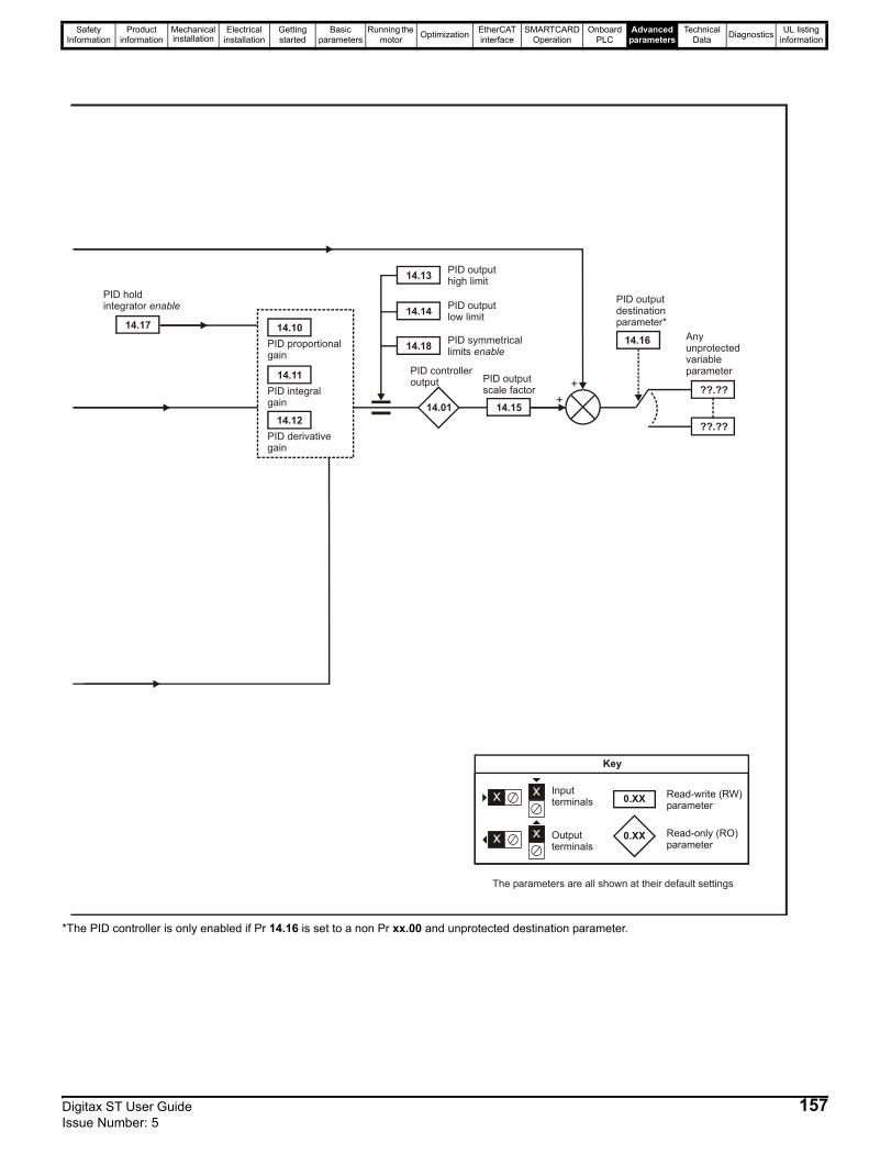
Safety Information
Product information
Mechanical installation
Electrical installation
Getting started
Basic parameters
Running the motor Optimization EtherCAT
interfaceSMARTCARD
OperationOnboard
PLCAdvanced
parametersTechnical
Data Diagnostics UL listing information
*The PID controller is only enabled if Pr 14.16 is set to a non Pr xx.00 and unprotected destination parameter.
14.10
14.11
14.12
14.17
14.13
14.14
14.18
14.01 14.15+
+
14.16
??.??
??.??
Any unprotectedvariable parameter
PID derivativegain
PID integralgain
PID proportionalgain
PID hold integrator enable
PID outputhigh limit
PID outputlow limit
PID symmetricallimits enable
PID controlleroutput PID output
scale factor
PID outputdestinationparameter*
0.XX
0.XX
Key
Read-write (RW) parameter
Read-only (RO) parameter
Inputterminals
Outputterminals
The parameters are all shown at their default settings
Digitax ST User Guide 157Issue Number: 5
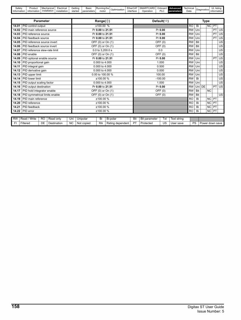
Safety Information
Product information
Mechanical installation
Electrical installation
Getting started
Basic parameters
Running the motor Optimization EtherCAT
interfaceSMARTCARD
OperationOnboard
PLCAdvanced
parametersTechnical
Data Diagnostics UL listing information
Parameter Range( ) Default( ) Type14.01 PID control output ±100.00 % RO Bi NC PT14.02 PID main reference source Pr 0.00 to 21.51 Pr 0.00 RW Uni PT US14.03 PID reference source Pr 0.00 to 21.51 Pr 0.00 RW Uni PT US14.04 PID feedback source Pr 0.00 to 21.51 Pr 0.00 RW Uni PT US14.05 PID reference source invert OFF (0) or On (1) OFF (0) RW Bit US14.06 PID feedback source invert OFF (0) or On (1) OFF (0) RW Bit US14.07 PID reference slew-rate limit 0.0 to 3,200.0 s 0.0 RW Uni US14.08 PID enable OFF (0) or On (1) OFF (0) RW Bit US14.09 PID optional enable source Pr 0.00 to 21.51 Pr 0.00 RW Uni PT US14.10 PID proportional gain 0.000 to 4.000 1.000 RW Uni US14.11 PID integral gain 0.000 to 4.000 0.500 RW Uni US14.12 PID derivative gain 0.000 to 4.000 0.000 RW Uni US14.13 PID upper limit 0.00 to 100.00 % 100.00 RW Uni US14.14 PID lower limit ±100.00 % -100.00 RW Bi US14.15 PID output scaling factor 0.000 to 4.000 1.000 RW Uni US14.16 PID output destination Pr 0.00 to 21.51 Pr 0.00 RW Uni DE PT US14.17 PID hold integrator enable OFF (0) or On (1) OFF (0) RW Bit NC14.18 PID symmetrical limits enable OFF (0) or On (1) OFF (0) RW Bit US14.19 PID main reference ±100.00 % RO Bi NC PT14.20 PID reference ±100.00 % RO Bi NC PT14.21 PID feedback ±100.00 % RO Bi NC PT14.22 PID error ±100.00 % RO Bi NC PT
RW Read / Write RO Read only Uni Unipolar Bi Bi-polar Bit Bit parameter Txt Text stringFI Filtered DE Destination NC Not copied RA Rating dependent PT Protected US User save PS Power down save
158 Digitax ST User Guide Issue Number: 5
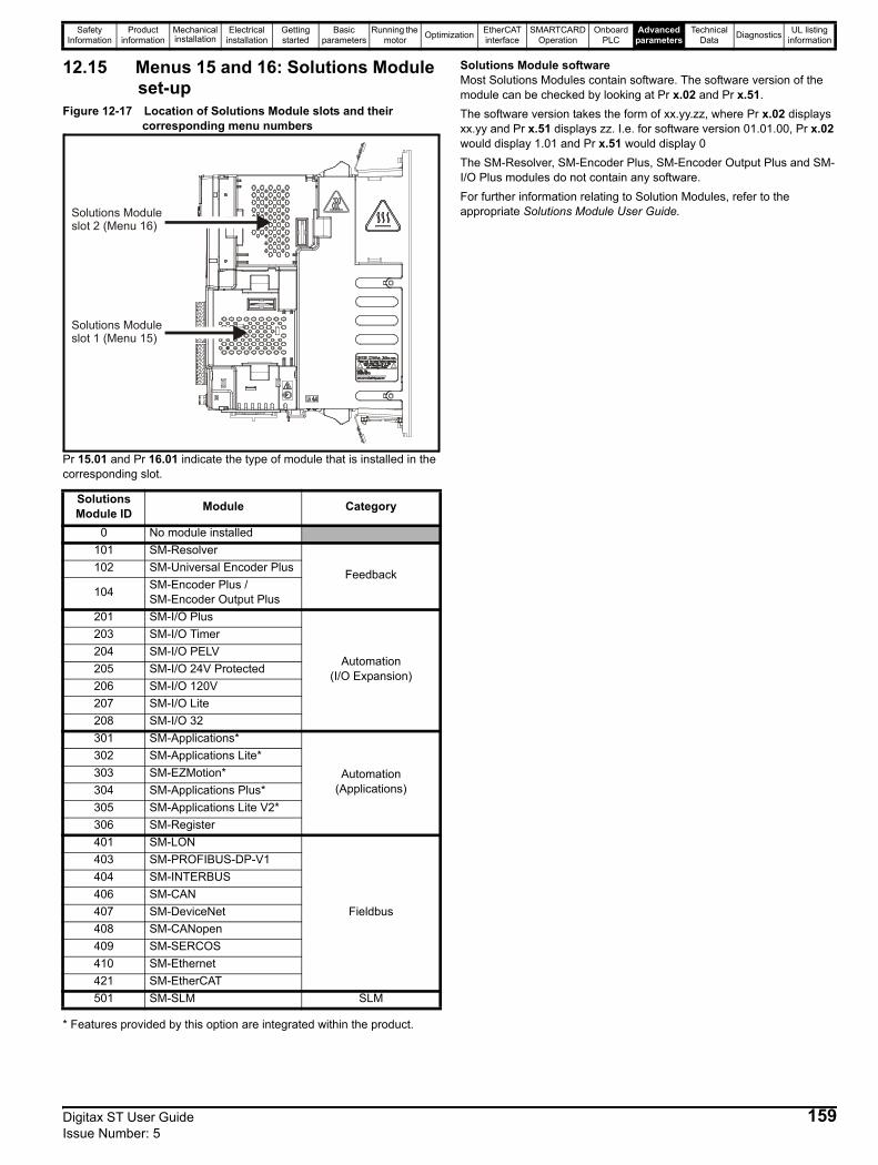
Safety Information
Product information
Mechanical installation
Electrical installation
Getting started
Basic parameters
Running the motor Optimization EtherCAT
interfaceSMARTCARD
OperationOnboard
PLCAdvanced
parametersTechnical
Data Diagnostics UL listing information
12.15 Menus 15 and 16: Solutions Module set-up
Figure 12-17 Location of Solutions Module slots and their corresponding menu numbers
Pr 15.01 and Pr 16.01 indicate the type of module that is installed in the corresponding slot.
* Features provided by this option are integrated within the product.
Solutions Module softwareMost Solutions Modules contain software. The software version of the module can be checked by looking at Pr x.02 and Pr x.51. The software version takes the form of xx.yy.zz, where Pr x.02 displays xx.yy and Pr x.51 displays zz. I.e. for software version 01.01.00, Pr x.02 would display 1.01 and Pr x.51 would display 0The SM-Resolver, SM-Encoder Plus, SM-Encoder Output Plus and SM-I/O Plus modules do not contain any software.For further information relating to Solution Modules, refer to the appropriate Solutions Module User Guide.
Solutions Module ID Module Category
0 No module installed101 SM-Resolver
Feedback102 SM-Universal Encoder Plus
104 SM-Encoder Plus / SM-Encoder Output Plus
201 SM-I/O Plus
Automation (I/O Expansion)
203 SM-I/O Timer204 SM-I/O PELV205 SM-I/O 24V Protected206 SM-I/O 120V207 SM-I/O Lite208 SM-I/O 32301 SM-Applications*
Automation(Applications)
302 SM-Applications Lite*303 SM-EZMotion*304 SM-Applications Plus*305 SM-Applications Lite V2*306 SM-Register401 SM-LON
Fieldbus
403 SM-PROFIBUS-DP-V1404 SM-INTERBUS406 SM-CAN407 SM-DeviceNet408 SM-CANopen409 SM-SERCOS410 SM-Ethernet421 SM-EtherCAT501 SM-SLM SLM
Solutions Moduleslot 2 (Menu 16)
Solutions Moduleslot 1 (Menu 15)
Digitax ST User Guide 159Issue Number: 5
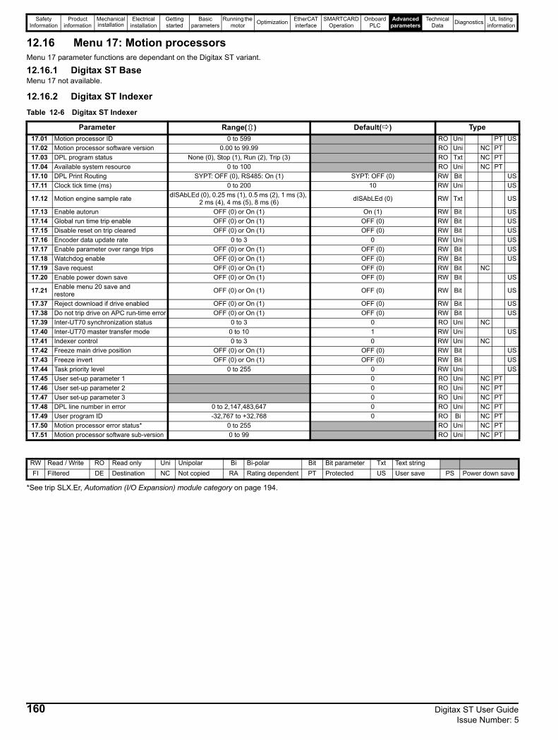
Safety Information
Product information
Mechanical installation
Electrical installation
Getting started
Basic parameters
Running the motor Optimization EtherCAT
interfaceSMARTCARD
OperationOnboard
PLCAdvanced
parametersTechnical
Data Diagnostics UL listing information
12.16 Menu 17: Motion processorsMenu 17 parameter functions are dependant on the Digitax ST variant.
12.16.1 Digitax ST BaseMenu 17 not available.
12.16.2 Digitax ST IndexerTable 12-6 Digitax ST Indexer
*See trip SLX.Er, Automation (I/O Expansion) module category on page 194.
Parameter Range( ) Default( ) Type17.01 Motion processor ID 0 to 599 RO Uni PT US17.02 Motion processor software version 0.00 to 99.99 RO Uni NC PT17.03 DPL program status None (0), Stop (1), Run (2), Trip (3) RO Txt NC PT17.04 Available system resource 0 to 100 RO Uni NC PT17.10 DPL Print Routing SYPT: OFF (0), RS485: On (1) SYPT: OFF (0) RW Bit US17.11 Clock tick time (ms) 0 to 200 10 RW Uni US
17.12 Motion engine sample rate dISAbLEd (0), 0.25 ms (1), 0.5 ms (2), 1 ms (3), 2 ms (4), 4 ms (5), 8 ms (6) dISAbLEd (0) RW Txt US
17.13 Enable autorun OFF (0) or On (1) On (1) RW Bit US17.14 Global run time trip enable OFF (0) or On (1) OFF (0) RW Bit US17.15 Disable reset on trip cleared OFF (0) or On (1) OFF (0) RW Bit US17.16 Encoder data update rate 0 to 3 0 RW Uni US17.17 Enable parameter over range trips OFF (0) or On (1) OFF (0) RW Bit US17.18 Watchdog enable OFF (0) or On (1) OFF (0) RW Bit US17.19 Save request OFF (0) or On (1) OFF (0) RW Bit NC17.20 Enable power down save OFF (0) or On (1) OFF (0) RW Bit US
17.21 Enable menu 20 save and restore OFF (0) or On (1) OFF (0) RW Bit US
17.37 Reject download if drive enabled OFF (0) or On (1) OFF (0) RW Bit US17.38 Do not trip drive on APC run-time error OFF (0) or On (1) OFF (0) RW Bit US17.39 Inter-UT70 synchronization status 0 to 3 0 RO Uni NC17.40 Inter-UT70 master transfer mode 0 to 10 1 RW Uni US17.41 Indexer control 0 to 3 0 RW Uni NC17.42 Freeze main drive position OFF (0) or On (1) OFF (0) RW Bit US17.43 Freeze invert OFF (0) or On (1) OFF (0) RW Bit US17.44 Task priority level 0 to 255 0 RW Uni US17.45 User set-up parameter 1 0 RO Uni NC PT17.46 User set-up parameter 2 0 RO Uni NC PT17.47 User set-up parameter 3 0 RO Uni NC PT17.48 DPL line number in error 0 to 2,147,483,647 0 RO Uni NC PT17.49 User program ID -32,767 to +32,768 0 RO Bi NC PT17.50 Motion processor error status* 0 to 255 RO Uni NC PT17.51 Motion processor software sub-version 0 to 99 RO Uni NC PT
RW Read / Write RO Read only Uni Unipolar Bi Bi-polar Bit Bit parameter Txt Text stringFI Filtered DE Destination NC Not copied RA Rating dependent PT Protected US User save PS Power down save
160 Digitax ST User Guide Issue Number: 5
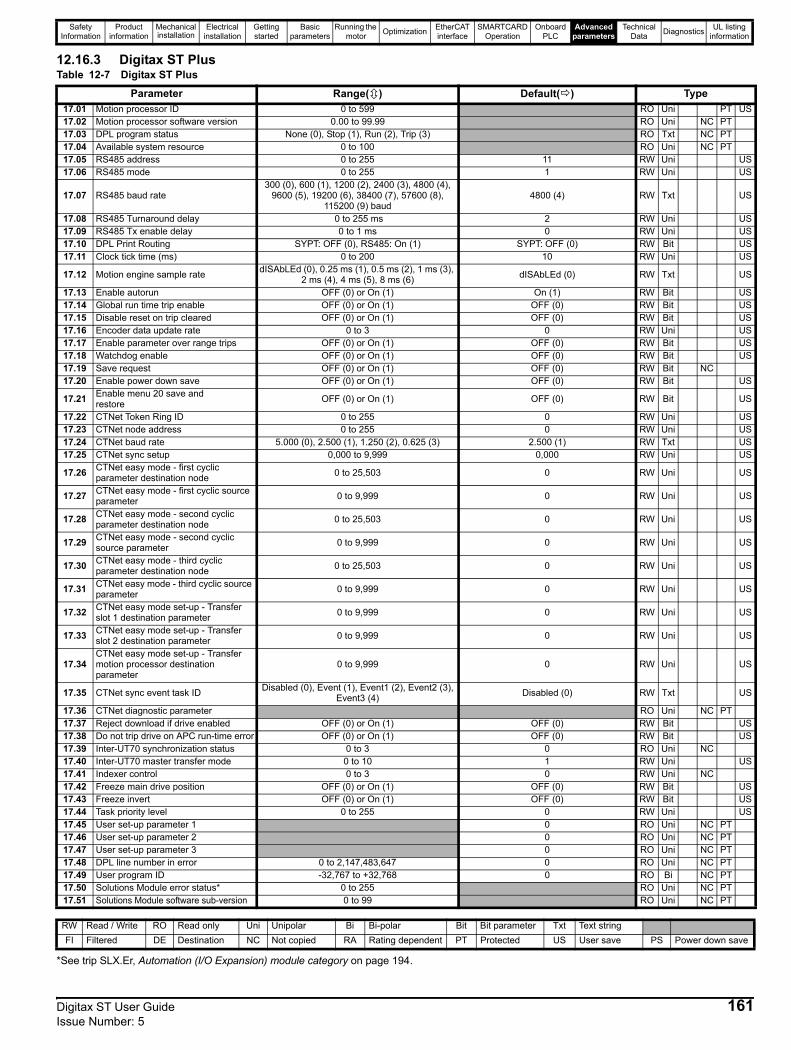
Safety Information
Product information
Mechanical installation
Electrical installation
Getting started
Basic parameters
Running the motor Optimization EtherCAT
interfaceSMARTCARD
OperationOnboard
PLCAdvanced
parametersTechnical
Data Diagnostics UL listing information
12.16.3 Digitax ST PlusTable 12-7 Digitax ST Plus
*See trip SLX.Er, Automation (I/O Expansion) module category on page 194.
Parameter Range( ) Default( ) Type17.01 Motion processor ID 0 to 599 RO Uni PT US17.02 Motion processor software version 0.00 to 99.99 RO Uni NC PT17.03 DPL program status None (0), Stop (1), Run (2), Trip (3) RO Txt NC PT17.04 Available system resource 0 to 100 RO Uni NC PT17.05 RS485 address 0 to 255 11 RW Uni US17.06 RS485 mode 0 to 255 1 RW Uni US
17.07 RS485 baud rate300 (0), 600 (1), 1200 (2), 2400 (3), 4800 (4),
9600 (5), 19200 (6), 38400 (7), 57600 (8), 115200 (9) baud
4800 (4) RW Txt US
17.08 RS485 Turnaround delay 0 to 255 ms 2 RW Uni US17.09 RS485 Tx enable delay 0 to 1 ms 0 RW Uni US17.10 DPL Print Routing SYPT: OFF (0), RS485: On (1) SYPT: OFF (0) RW Bit US17.11 Clock tick time (ms) 0 to 200 10 RW Uni US
17.12 Motion engine sample rate dISAbLEd (0), 0.25 ms (1), 0.5 ms (2), 1 ms (3), 2 ms (4), 4 ms (5), 8 ms (6) dISAbLEd (0) RW Txt US
17.13 Enable autorun OFF (0) or On (1) On (1) RW Bit US17.14 Global run time trip enable OFF (0) or On (1) OFF (0) RW Bit US17.15 Disable reset on trip cleared OFF (0) or On (1) OFF (0) RW Bit US17.16 Encoder data update rate 0 to 3 0 RW Uni US17.17 Enable parameter over range trips OFF (0) or On (1) OFF (0) RW Bit US17.18 Watchdog enable OFF (0) or On (1) OFF (0) RW Bit US17.19 Save request OFF (0) or On (1) OFF (0) RW Bit NC17.20 Enable power down save OFF (0) or On (1) OFF (0) RW Bit US
17.21 Enable menu 20 save and restore OFF (0) or On (1) OFF (0) RW Bit US
17.22 CTNet Token Ring ID 0 to 255 0 RW Uni US17.23 CTNet node address 0 to 255 0 RW Uni US17.24 CTNet baud rate 5.000 (0), 2.500 (1), 1.250 (2), 0.625 (3) 2.500 (1) RW Txt US17.25 CTNet sync setup 0,000 to 9,999 0,000 RW Uni US
17.26 CTNet easy mode - first cyclic parameter destination node 0 to 25,503 0 RW Uni US
17.27 CTNet easy mode - first cyclic source parameter 0 to 9,999 0 RW Uni US
17.28 CTNet easy mode - second cyclic parameter destination node 0 to 25,503 0 RW Uni US
17.29 CTNet easy mode - second cyclic source parameter 0 to 9,999 0 RW Uni US
17.30 CTNet easy mode - third cyclic parameter destination node 0 to 25,503 0 RW Uni US
17.31 CTNet easy mode - third cyclic source parameter 0 to 9,999 0 RW Uni US
17.32 CTNet easy mode set-up - Transfer slot 1 destination parameter 0 to 9,999 0 RW Uni US
17.33 CTNet easy mode set-up - Transfer slot 2 destination parameter 0 to 9,999 0 RW Uni US
17.34CTNet easy mode set-up - Transfer motion processor destination parameter
0 to 9,999 0 RW Uni US
17.35 CTNet sync event task ID Disabled (0), Event (1), Event1 (2), Event2 (3),Event3 (4) Disabled (0) RW Txt US
17.36 CTNet diagnostic parameter RO Uni NC PT17.37 Reject download if drive enabled OFF (0) or On (1) OFF (0) RW Bit US17.38 Do not trip drive on APC run-time error OFF (0) or On (1) OFF (0) RW Bit US17.39 Inter-UT70 synchronization status 0 to 3 0 RO Uni NC17.40 Inter-UT70 master transfer mode 0 to 10 1 RW Uni US17.41 Indexer control 0 to 3 0 RW Uni NC17.42 Freeze main drive position OFF (0) or On (1) OFF (0) RW Bit US17.43 Freeze invert OFF (0) or On (1) OFF (0) RW Bit US17.44 Task priority level 0 to 255 0 RW Uni US17.45 User set-up parameter 1 0 RO Uni NC PT17.46 User set-up parameter 2 0 RO Uni NC PT17.47 User set-up parameter 3 0 RO Uni NC PT17.48 DPL line number in error 0 to 2,147,483,647 0 RO Uni NC PT17.49 User program ID -32,767 to +32,768 0 RO Bi NC PT17.50 Solutions Module error status* 0 to 255 RO Uni NC PT17.51 Solutions Module software sub-version 0 to 99 RO Uni NC PT
RW Read / Write RO Read only Uni Unipolar Bi Bi-polar Bit Bit parameter Txt Text stringFI Filtered DE Destination NC Not copied RA Rating dependent PT Protected US User save PS Power down save
Digitax ST User Guide 161Issue Number: 5
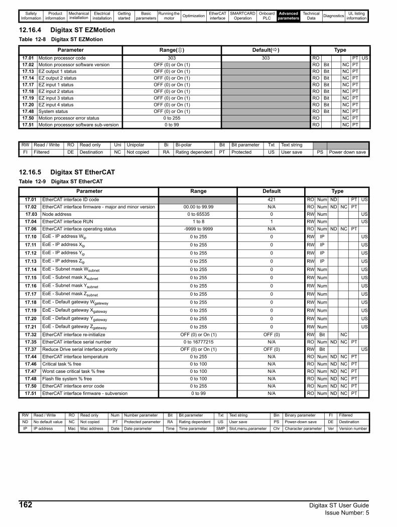
Safety Information
Product information
Mechanical installation
Electrical installation
Getting started
Basic parameters
Running the motor Optimization EtherCAT
interfaceSMARTCARD
OperationOnboard
PLCAdvanced
parametersTechnical
Data Diagnostics UL listing information
12.16.4 Digitax ST EZMotionTable 12-8 Digitax ST EZMotion
12.16.5 Digitax ST EtherCATTable 12-9 Digitax ST EtherCAT
Parameter Range( ) Default( ) Type17.01 Motion processor code 303 303 RO PT US17.02 Motion processor software version OFF (0) or On (1) RO Bit NC PT17.13 EZ output 1 status OFF (0) or On (1) RO Bit NC PT17.14 EZ output 2 status OFF (0) or On (1) RO Bit NC PT17.17 EZ input 1 status OFF (0) or On (1) RO Bit NC PT17.18 EZ input 2 status OFF (0) or On (1) RO Bit NC PT17.19 EZ input 3 status OFF (0) or On (1) RO Bit NC PT17.20 EZ input 4 status OFF (0) or On (1) RO Bit NC PT17.48 System status OFF (0) or On (1) RO Bit NC PT17.50 Motion processor error status 0 to 255 RO NC PT17.51 Motion processor software sub-version 0 to 99 RO NC PT
RW Read / Write RO Read only Uni Unipolar Bi Bi-polar Bit Bit parameter Txt Text stringFI Filtered DE Destination NC Not copied RA Rating dependent PT Protected US User save PS Power down save
Parameter Range Default Type17.01 EtherCAT interface ID code 421 RO Num ND PT US17.02 EtherCAT interface firmware - major and minor version 00.00 to 99.99 N/A RO Num ND NC PT 17.03 Node address 0 to 65535 0 RW Num US17.04 EtherCAT interface RUN 1 to 8 1 RW Num US17.06 EtherCAT interface operating status -9999 to 9999 N/A RO Num ND NC PT17.10 EoE - IP address Wip 0 to 255 0 RW IP US
17.11 EoE - IP address Xip 0 to 255 0 RW IP US
17.12 EoE - IP address Yip 0 to 255 0 RW IP US
17.13 EoE - IP address Zip 0 to 255 0 RW IP US
17.14 EoE - Subnet mask Wsubnet 0 to 255 0 RW Num US
17.15 EoE - Subnet mask Xsubnet 0 to 255 0 RW Num US
17.16 EoE - Subnet mask Ysubnet 0 to 255 0 RW Num US
17.17 EoE - Subnet mask Zsubnet 0 to 255 0 RW Num US
17.18 EoE - Default gateway Wgateway 0 to 255 0 RW Num US
17.19 EoE - Default gateway Xgateway 0 to 255 0 RW Num US
17.20 EoE - Default gateway Ygateway 0 to 255 0 RW Num US
17.21 EoE - Default gateway Zgateway 0 to 255 0 RW Num US17.32 EtherCAT interface re-initialize OFF (0) or On (1) OFF (0) RW Bit NC17.35 EtherCAT interface serial number 0 to 16777215 N/A RO Num ND NC PT17.37 Reduce Drive serial interface priority OFF (0) or On (1) OFF (0) RW Bit US17.44 EtherCAT interface temperature 0 to 255 N/A RO Num ND NC PT17.46 Critical task % free 0 to 100 N/A RO Num ND NC PT17.47 Worst case critical task % free 0 to 100 N/A RO Num ND NC PT17.48 Flash file system % free 0 to 100 N/A RO Num ND NC PT17.50 EtherCAT interface error code 0 to 255 N/A RO Num ND NC PT17.51 EtherCAT interface firmware - subversion 0 to 99 N/A RO Num ND NC PT
RW Read / Write RO Read only Num Number parameter Bit Bit parameter Txt Text string Bin Binary parameter FI Filtered
ND No default value NC Not copied PT Protected parameter RA Rating dependent US User save PS Power-down save DE Destination
IP IP address Mac Mac address Date Date parameter Time Time parameter SMP Slot,menu,parameter Chr Character parameter Ver Version number
162 Digitax ST User Guide Issue Number: 5

Safety Information
Product information
Mechanical installation
Electrical installation
Getting started
Basic parameters
Running the motor Optimization EtherCAT
interfaceSMARTCARD
OperationOnboard
PLCAdvanced
parametersTechnical
Data Diagnostics UL listing information
12.17 Menu 18: Application menu 1
12.18 Menu 19: Application menu 2
12.19 Menu 20: Application menu 3
Menu 20 parameters are transferred to the SMARTCARD when a 4yyy transfer is performed. See section 10.2.1 Writing to the SMARTCARD on page 102 for more information.
Parameter Range( ) Default( ) Type
18.01 Application menu 1 power-down saved integer -32,768 to +32,767 0 RW Bi NC PS
18.02 to18.10 Application menu 1 read-only integer -32,768 to +32,767 0 RO Bi NC
18.11 to 18.30 Application menu 1 read-write integer -32,768 to +32,767 0 RW Bi US
18.31 to 18.50 Application menu 1 read-write bit OFF (0) or On (1) 0 RW Bit US
Parameter Range( ) Default( ) Type
19.01 Application menu 2 power-down saved integer -32,768 to +32,767 0 RW Bi NC PS
19.02 to19.10 Application menu 2 read-only integer -32,768 to +32,767 0 RO Bi NC
19.11 to 19.30 Application menu 2 read-write integer -32,768 to +32,767 0 RW Bi US
19.31 to 19.50 Application menu 2 read-write bit OFF (0) or On (1) 0 RW Bit US
Parameter Range( ) Default( ) Type20.01 to
20.20 Application menu 3 read-write integer -32,768 to +32,767 0 RW Bi NC
20.21 to 20.40
Application menu 3 read-write long integer -231 to 231-1 0 RW Bi NC
RW Read / Write RO Read only Uni Unipolar Bi Bi-polar Bit Bit parameter Txt Text stringFI Filtered DE Destination NC Not copied RA Rating dependent PT Protected US User save PS Power down save
Digitax ST User Guide 163Issue Number: 5
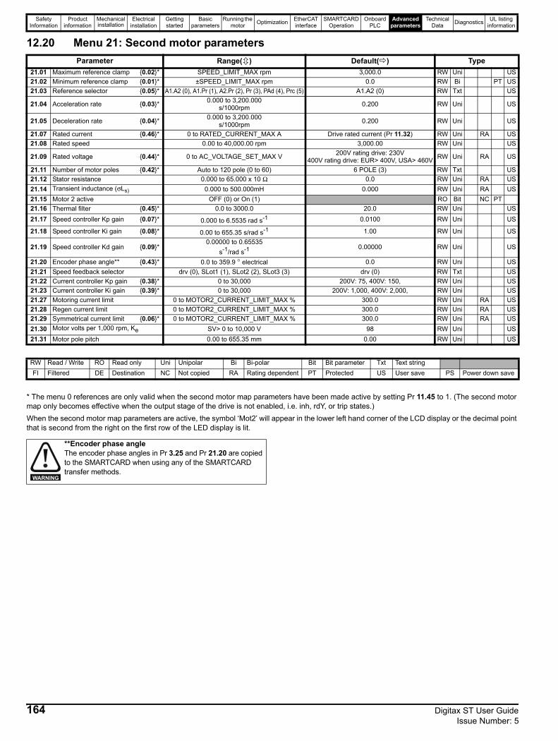
Safety Information
Product information
Mechanical installation
Electrical installation
Getting started
Basic parameters
Running the motor Optimization EtherCAT
interfaceSMARTCARD
OperationOnboard
PLCAdvanced
parametersTechnical
Data Diagnostics UL listing information
12.20 Menu 21: Second motor parameters
* The menu 0 references are only valid when the second motor map parameters have been made active by setting Pr 11.45 to 1. (The second motor map only becomes effective when the output stage of the drive is not enabled, i.e. inh, rdY, or trip states.)When the second motor map parameters are active, the symbol ‘Mot2’ will appear in the lower left hand corner of the LCD display or the decimal point that is second from the right on the first row of the LED display is lit.
Parameter Range( ) Default( ) Type21.01 Maximum reference clamp {0.02}* SPEED_LIMIT_MAX rpm 3,000.0 RW Uni US21.02 Minimum reference clamp {0.01}* ±SPEED_LIMIT_MAX rpm 0.0 RW Bi PT US21.03 Reference selector {0.05}* A1.A2 (0), A1.Pr (1), A2.Pr (2), Pr (3), PAd (4), Prc (5) A1.A2 (0) RW Txt US
21.04 Acceleration rate {0.03}* 0.000 to 3,200.000 s/1000rpm 0.200 RW Uni US
21.05 Deceleration rate {0.04}* 0.000 to 3,200.000 s/1000rpm 0.200 RW Uni US
21.07 Rated current {0.46}* 0 to RATED_CURRENT_MAX A Drive rated current (Pr 11.32) RW Uni RA US21.08 Rated speed 0.00 to 40,000.00 rpm 3,000.00 RW Uni US
21.09 Rated voltage {0.44}* 0 to AC_VOLTAGE_SET_MAX V 200V rating drive: 230V400V rating drive: EUR> 400V, USA> 460V RW Uni RA US
21.11 Number of motor poles {0.42}* Auto to 120 pole (0 to 60) 6 POLE (3) RW Txt US21.12 Stator resistance 0.000 to 65.000 x 10 Ω 0.0 RW Uni RA US21.14 Transient inductance (σLs) 0.000 to 500.000mH 0.000 RW Uni RA US21.15 Motor 2 active OFF (0) or On (1) RO Bit NC PT21.16 Thermal filter {0.45}* 0.0 to 3000.0 20.0 RW Uni US21.17 Speed controller Kp gain {0.07}* 0.000 to 6.5535 rad s-1 0.0100 RW Uni US
21.18 Speed controller Ki gain {0.08}* 0.00 to 655.35 s/rad s-1 1.00 RW Uni US
21.19 Speed controller Kd gain {0.09}*0.00000 to 0.65535
s-1/rad s-1 0.00000 RW Uni US
21.20 Encoder phase angle** {0.43}* 0.0 to 359.9 ° electrical 0.0 RW Uni US21.21 Speed feedback selector drv (0), SLot1 (1), SLot2 (2), SLot3 (3) drv (0) RW Txt US21.22 Current controller Kp gain {0.38}* 0 to 30,000 200V: 75, 400V: 150, RW Uni US21.23 Current controller Ki gain {0.39}* 0 to 30,000 200V: 1,000, 400V: 2,000, RW Uni US21.27 Motoring current limit 0 to MOTOR2_CURRENT_LIMIT_MAX % 300.0 RW Uni RA US21.28 Regen current limit 0 to MOTOR2_CURRENT_LIMIT_MAX % 300.0 RW Uni RA US21.29 Symmetrical current limit {0.06}* 0 to MOTOR2_CURRENT_LIMIT_MAX % 300.0 RW Uni RA US21.30 Motor volts per 1,000 rpm, Ke SV> 0 to 10,000 V 98 RW Uni US21.31 Motor pole pitch 0.00 to 655.35 mm 0.00 RW Uni US
RW Read / Write RO Read only Uni Unipolar Bi Bi-polar Bit Bit parameter Txt Text stringFI Filtered DE Destination NC Not copied RA Rating dependent PT Protected US User save PS Power down save
**Encoder phase angle The encoder phase angles in Pr 3.25 and Pr 21.20 are copied to the SMARTCARD when using any of the SMARTCARD transfer methods.
WARNING
164 Digitax ST User Guide Issue Number: 5
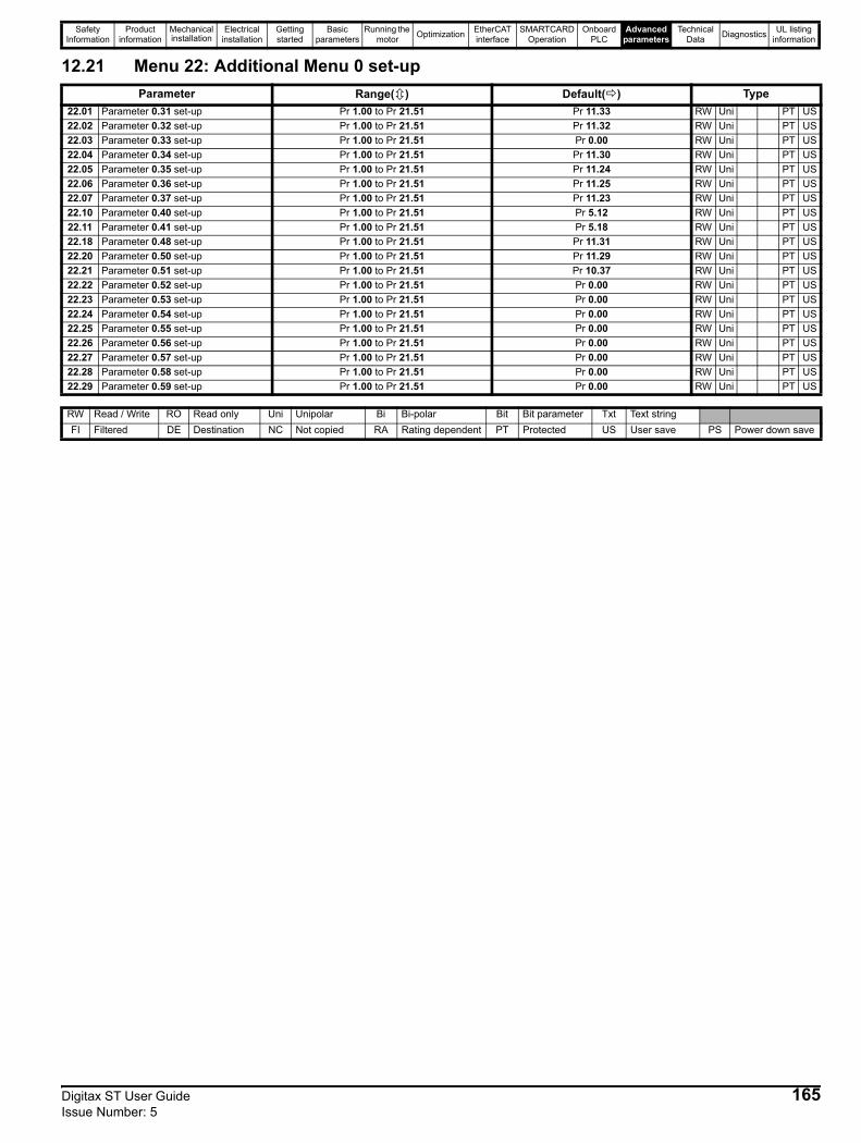
Safety Information
Product information
Mechanical installation
Electrical installation
Getting started
Basic parameters
Running the motor Optimization EtherCAT
interfaceSMARTCARD
OperationOnboard
PLCAdvanced
parametersTechnical
Data Diagnostics UL listing information
12.21 Menu 22: Additional Menu 0 set-upParameter Range( ) Default( ) Type
22.01 Parameter 0.31 set-up Pr 1.00 to Pr 21.51 Pr 11.33 RW Uni PT US22.02 Parameter 0.32 set-up Pr 1.00 to Pr 21.51 Pr 11.32 RW Uni PT US22.03 Parameter 0.33 set-up Pr 1.00 to Pr 21.51 Pr 0.00 RW Uni PT US22.04 Parameter 0.34 set-up Pr 1.00 to Pr 21.51 Pr 11.30 RW Uni PT US22.05 Parameter 0.35 set-up Pr 1.00 to Pr 21.51 Pr 11.24 RW Uni PT US22.06 Parameter 0.36 set-up Pr 1.00 to Pr 21.51 Pr 11.25 RW Uni PT US22.07 Parameter 0.37 set-up Pr 1.00 to Pr 21.51 Pr 11.23 RW Uni PT US22.10 Parameter 0.40 set-up Pr 1.00 to Pr 21.51 Pr 5.12 RW Uni PT US22.11 Parameter 0.41 set-up Pr 1.00 to Pr 21.51 Pr 5.18 RW Uni PT US22.18 Parameter 0.48 set-up Pr 1.00 to Pr 21.51 Pr 11.31 RW Uni PT US22.20 Parameter 0.50 set-up Pr 1.00 to Pr 21.51 Pr 11.29 RW Uni PT US22.21 Parameter 0.51 set-up Pr 1.00 to Pr 21.51 Pr 10.37 RW Uni PT US22.22 Parameter 0.52 set-up Pr 1.00 to Pr 21.51 Pr 0.00 RW Uni PT US22.23 Parameter 0.53 set-up Pr 1.00 to Pr 21.51 Pr 0.00 RW Uni PT US22.24 Parameter 0.54 set-up Pr 1.00 to Pr 21.51 Pr 0.00 RW Uni PT US22.25 Parameter 0.55 set-up Pr 1.00 to Pr 21.51 Pr 0.00 RW Uni PT US22.26 Parameter 0.56 set-up Pr 1.00 to Pr 21.51 Pr 0.00 RW Uni PT US22.27 Parameter 0.57 set-up Pr 1.00 to Pr 21.51 Pr 0.00 RW Uni PT US22.28 Parameter 0.58 set-up Pr 1.00 to Pr 21.51 Pr 0.00 RW Uni PT US22.29 Parameter 0.59 set-up Pr 1.00 to Pr 21.51 Pr 0.00 RW Uni PT US
RW Read / Write RO Read only Uni Unipolar Bi Bi-polar Bit Bit parameter Txt Text stringFI Filtered DE Destination NC Not copied RA Rating dependent PT Protected US User save PS Power down save
Digitax ST User Guide 165Issue Number: 5

Safety Information
Product information
Mechanical installation
Electrical installation
Getting started
Basic parameters
Running the motor Optimization EtherCAT
interfaceSMARTCARD
OperationOnboard
PLCAdvanced
parametersTechnical
Data Diagnostics UL listing information
12.22 Advanced featuresThis section gives information on some of the advanced functions of the drive. For additional information see the Advanced User Guide.
12.22.1 Reference modes
If Pr 8.39 is set to OFF (0), then the setting of Pr 1.14 automatically changes the operation of digital inputs T28 and T29 by configuring the destination parameters Pr 8.25 and Pr 8.26. To allow Pr 8.25 and Pr 8.26 to be changed manually by the user, the automatic set-up must be disabled by setting Pr 8.39 to 1.If Pr 8.39 is 0 and Pr 1.14 is changed, then a drive reset is required before the function of terminal T28 or T29 will become active.
* Setting Pr 1.15 to 9 enables the Preset reference scan timer. With the scan timer enabled the preset references are selected automatically in turn. Pr 1.16 defines the time between each change.** Jog forward can only be selected when the drive is in either the ready (rdy), inhibit (inh) or trip states.
Reference modes Pr 1.14, Pr 1.15 and Pr 8.39Braking modes Pr 2.04 and Pr 2.08S ramps Pr 2.06 and Pr 2.07Torque modes Pr 4.08 and Pr 4.11Stop modes Pr 6.01 and Pr 6.08Main loss modes Pr 6.03, Pr 6.48, Pr 4.13 and Pr 4.14Start/stop logic modes Pr 6.04 and Pr 6.40Position loop modes Pr 13.10Fast disable Pr 6.29
1.14 Reference selectorRW Txt NC US
A1.A2 (0), A1.Pr (2), A2.Pr (2), Pr (3), PAd (4), Prc (5) A1.A2 (0)
1.15 Preset reference selectorRW Uni NC US
0 to 9 0
8.39 T28 and T29 auto-selection disableRW Bit US
OFF (0) or On (1) OFF (0)
Table 12-10 Active reference
Pr 1.14 Pr 1.15Digital Input T28 Digital Input T29
Pr 1.49 Pr 1.50 Active ReferenceState Function State Function
A1.A2 (0)
0 or 10
Local Remote
Jog forward**
1 1 Analog input 11 2 1 Analog input 2
2 to 8 No function 1 or 2 2 to 8 Preset reference 2 to 8
9 *0
Local Remote1 1 Analog input 1
1 2 1 Analog input 2No function 1 or 2 2 to 8 Preset reference 2 to 8
A1.Pr (1)
0
0
Preset select bit 00
Preset select bit 1
1
1 Analog input 11 2 Preset reference 20
13 Preset reference 3
1 4 Preset reference 41
No function No function
1 Analog input 12 to 8 2 to 8 Preset reference 2 to 8
9 *1 Analog input 1
2 to 8 Preset reference 2 to 8
A2.Pr (2)
0
0
Preset select bit 00
Preset select bit 1
2
1 Analog input 21 2 Preset reference 20
13 Preset reference 3
1 4 Preset reference 41
No function No function
1 Analog input 22 to 8 2 to 8 Preset reference 2 to 8
9 *1 Analog input 2
2 to 8 Preset reference 2 to 8
Pr (3)0
0
Preset select bit 00
Preset select bit 13
1 Preset reference 11 2 Preset reference 20
13 Preset reference 3
1 4 Preset reference 41 to 8
No function No function1 to 8 Preset reference 1 to 8
9 * 1 to 8 Preset reference 1 to 8PAd (4) No function No function 4 Keypad referencePrc (5) No function No function 5 Precision reference
166 Digitax ST User Guide Issue Number: 5
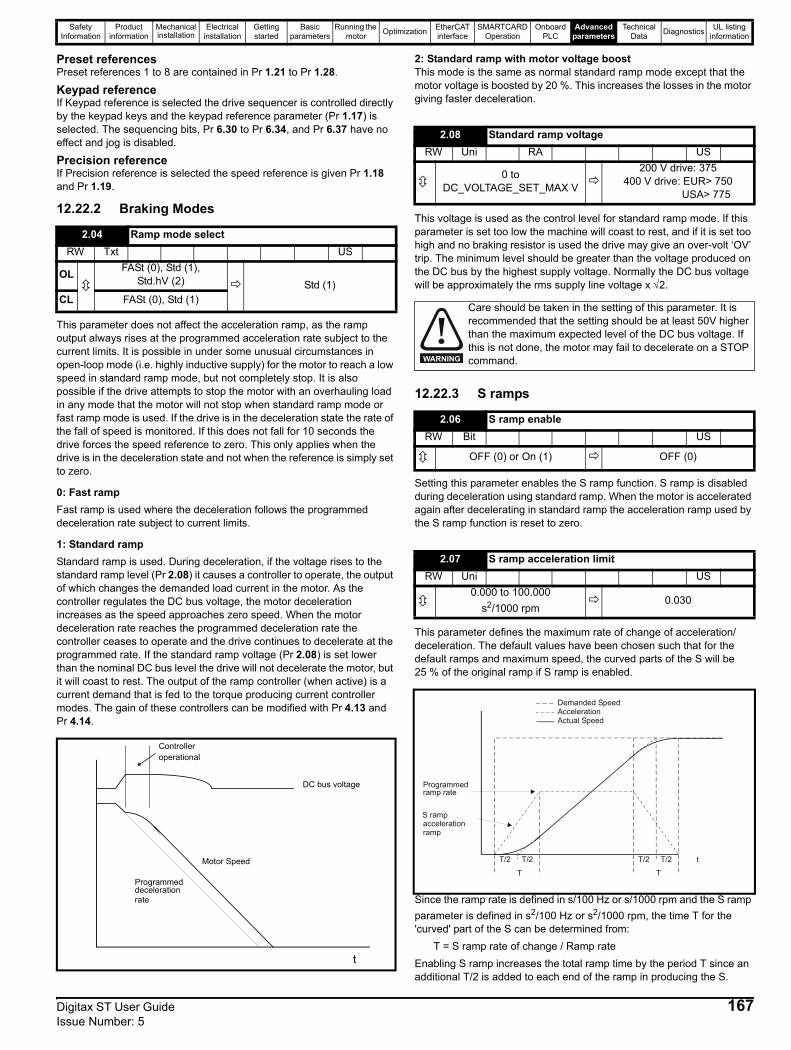
Safety Information
Product information
Mechanical installation
Electrical installation
Getting started
Basic parameters
Running the motor Optimization EtherCAT
interfaceSMARTCARD
OperationOnboard
PLCAdvanced
parametersTechnical
Data Diagnostics UL listing information
Preset referencesPreset references 1 to 8 are contained in Pr 1.21 to Pr 1.28.
Keypad referenceIf Keypad reference is selected the drive sequencer is controlled directly by the keypad keys and the keypad reference parameter (Pr 1.17) is selected. The sequencing bits, Pr 6.30 to Pr 6.34, and Pr 6.37 have no effect and jog is disabled.
Precision referenceIf Precision reference is selected the speed reference is given Pr 1.18 and Pr 1.19.
12.22.2 Braking Modes
This parameter does not affect the acceleration ramp, as the ramp output always rises at the programmed acceleration rate subject to the current limits. It is possible in under some unusual circumstances in open-loop mode (i.e. highly inductive supply) for the motor to reach a low speed in standard ramp mode, but not completely stop. It is also possible if the drive attempts to stop the motor with an overhauling load in any mode that the motor will not stop when standard ramp mode or fast ramp mode is used. If the drive is in the deceleration state the rate of the fall of speed is monitored. If this does not fall for 10 seconds the drive forces the speed reference to zero. This only applies when the drive is in the deceleration state and not when the reference is simply set to zero.
0: Fast rampFast ramp is used where the deceleration follows the programmed deceleration rate subject to current limits.
1: Standard rampStandard ramp is used. During deceleration, if the voltage rises to the standard ramp level (Pr 2.08) it causes a controller to operate, the output of which changes the demanded load current in the motor. As the controller regulates the DC bus voltage, the motor deceleration increases as the speed approaches zero speed. When the motor deceleration rate reaches the programmed deceleration rate the controller ceases to operate and the drive continues to decelerate at the programmed rate. If the standard ramp voltage (Pr 2.08) is set lower than the nominal DC bus level the drive will not decelerate the motor, but it will coast to rest. The output of the ramp controller (when active) is a current demand that is fed to the torque producing current controller modes. The gain of these controllers can be modified with Pr 4.13 and Pr 4.14.
2: Standard ramp with motor voltage boostThis mode is the same as normal standard ramp mode except that the motor voltage is boosted by 20 %. This increases the losses in the motor giving faster deceleration.
This voltage is used as the control level for standard ramp mode. If this parameter is set too low the machine will coast to rest, and if it is set too high and no braking resistor is used the drive may give an over-volt ‘OV’ trip. The minimum level should be greater than the voltage produced on the DC bus by the highest supply voltage. Normally the DC bus voltage will be approximately the rms supply line voltage x √2.
12.22.3 S ramps
Setting this parameter enables the S ramp function. S ramp is disabled during deceleration using standard ramp. When the motor is accelerated again after decelerating in standard ramp the acceleration ramp used by the S ramp function is reset to zero.
This parameter defines the maximum rate of change of acceleration/deceleration. The default values have been chosen such that for the default ramps and maximum speed, the curved parts of the S will be 25 % of the original ramp if S ramp is enabled.
Since the ramp rate is defined in s/100 Hz or s/1000 rpm and the S ramp parameter is defined in s2/100 Hz or s2/1000 rpm, the time T for the 'curved' part of the S can be determined from:
T = S ramp rate of change / Ramp rateEnabling S ramp increases the total ramp time by the period T since an additional T/2 is added to each end of the ramp in producing the S.
2.04 Ramp mode selectRW Txt US
OL FASt (0), Std (1), Std.hV (2) Std (1)
CL FASt (0), Std (1)
DC bus voltage
Motor Speed
Programmeddecelerationrate
t
Controlleroperational
2.08 Standard ramp voltageRW Uni RA US
0 to DC_VOLTAGE_SET_MAX V
200 V drive: 375400 V drive: EUR> 750 USA> 775
Care should be taken in the setting of this parameter. It is recommended that the setting should be at least 50V higher than the maximum expected level of the DC bus voltage. If this is not done, the motor may fail to decelerate on a STOP command.
2.06 S ramp enableRW Bit US
OFF (0) or On (1) OFF (0)
2.07 S ramp acceleration limitRW Uni US
0.000 to 100.000s2/1000 rpm
0.030
WARNING
t
AccelerationActual Speed
Programmedramp rate
T T
T/2 T/2 T/2T/2
S rampaccelerationramp
Demanded Speed
Digitax ST User Guide 167Issue Number: 5
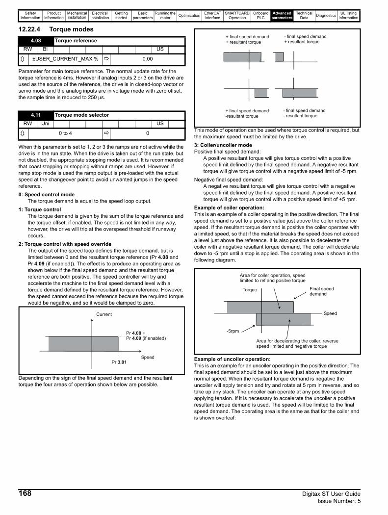
Safety Information
Product information
Mechanical installation
Electrical installation
Getting started
Basic parameters
Running the motor Optimization EtherCAT
interfaceSMARTCARD
OperationOnboard
PLCAdvanced
parametersTechnical
Data Diagnostics UL listing information
12.22.4 Torque modes
Parameter for main torque reference. The normal update rate for the torque reference is 4ms. However if analog inputs 2 or 3 on the drive are used as the source of the reference, the drive is in closed-loop vector or servo mode and the analog inputs are in voltage mode with zero offset, the sample time is reduced to 250 μs.
When this parameter is set to 1, 2 or 3 the ramps are not active while the drive is in the run state. When the drive is taken out of the run state, but not disabled, the appropriate stopping mode is used. It is recommended that coast stopping or stopping without ramps are used. However, if ramp stop mode is used the ramp output is pre-loaded with the actual speed at the changeover point to avoid unwanted jumps in the speed reference.0: Speed control mode
The torque demand is equal to the speed loop output.1: Torque control
The torque demand is given by the sum of the torque reference and the torque offset, if enabled. The speed is not limited in any way, however, the drive will trip at the overspeed threshold if runaway occurs.
2: Torque control with speed overrideThe output of the speed loop defines the torque demand, but is limited between 0 and the resultant torque reference (Pr 4.08 and Pr 4.09 (if enabled)). The effect is to produce an operating area as shown below if the final speed demand and the resultant torque reference are both positive. The speed controller will try and accelerate the machine to the final speed demand level with a torque demand defined by the resultant torque reference. However, the speed cannot exceed the reference because the required torque would be negative, and so it would be clamped to zero.
Depending on the sign of the final speed demand and the resultant torque the four areas of operation shown below are possible.
This mode of operation can be used where torque control is required, but the maximum speed must be limited by the drive.3: Coiler/uncoiler modePositive final speed demand:
A positive resultant torque will give torque control with a positive speed limit defined by the final speed demand. A negative resultant torque will give torque control with a negative speed limit of -5 rpm.
Negative final speed demand: A negative resultant torque will give torque control with a negative speed limit defined by the final speed demand. A positive resultant torque will give torque control with a positive speed limit of +5 rpm.
Example of coiler operation:This is an example of a coiler operating in the positive direction. The final speed demand is set to a positive value just above the coiler reference speed. If the resultant torque demand is positive the coiler operates with a limited speed, so that if the material breaks the speed does not exceed a level just above the reference. It is also possible to decelerate the coiler with a negative resultant torque demand. The coiler will decelerate down to -5 rpm until a stop is applied. The operating area is shown in the following diagram.
Example of uncoiler operation:This is an example for an uncoiler operating in the positive direction. The final speed demand should be set to a level just above the maximum normal speed. When the resultant torque demand is negative the uncoiler will apply tension and try and rotate at 5 rpm in reverse, and so take up any slack. The uncoiler can operate at any positive speed applying tension. If it is necessary to accelerate the uncoiler a positive resultant torque demand is used. The speed will be limited to the final speed demand. The operating area is the same as that for the coiler and is shown overleaf:
4.08 Torque referenceRW Bi US
±USER_CURRENT_MAX % 0.00
4.11 Torque mode selectorRW Uni US
0 to 4 0
Pr +4.08Pr (if enabled)4.09
Pr 3.01Speed
Current
+ final speed demand+ resultant torque
- final speed demand+ resultant torque
+ final speed demand-resultant torque
- final speed demand- resultant torque
Final speeddemand
Area for coiler operation, speedlimited to ref and positve torque
Area for decelerating the coiler, reversespeed limited and negative torque
-5rpm
Speed
Torque
168 Digitax ST User Guide Issue Number: 5
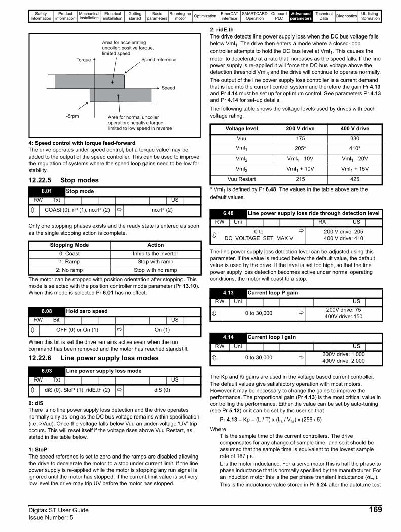
Safety Information
Product information
Mechanical installation
Electrical installation
Getting started
Basic parameters
Running the motor Optimization EtherCAT
interfaceSMARTCARD
OperationOnboard
PLCAdvanced
parametersTechnical
Data Diagnostics UL listing information
4: Speed control with torque feed-forwardThe drive operates under speed control, but a torque value may be added to the output of the speed controller. This can be used to improve the regulation of systems where the speed loop gains need to be low for stability.
12.22.5 Stop modes
Only one stopping phases exists and the ready state is entered as soon as the single stopping action is complete.
The motor can be stopped with position orientation after stopping. This mode is selected with the position controller mode parameter (Pr 13.10). When this mode is selected Pr 6.01 has no effect.
When this bit is set the drive remains active even when the run command has been removed and the motor has reached standstill.
12.22.6 Line power supply loss modes
0: diSThere is no line power supply loss detection and the drive operates normally only as long as the DC bus voltage remains within specification (i.e. >Vuu). Once the voltage falls below Vuu an under-voltage ‘UV’ trip occurs. This will reset itself if the voltage rises above Vuu Restart, as stated in the table below.
1: StoPThe speed reference is set to zero and the ramps are disabled allowing the drive to decelerate the motor to a stop under current limit. If the line power supply is re-applied while the motor is stopping any run signal is ignored until the motor has stopped. If the current limit value is set very low level the drive may trip UV before the motor has stopped.
2: ridE.thThe drive detects line power supply loss when the DC bus voltage falls below Vml1. The drive then enters a mode where a closed-loop controller attempts to hold the DC bus level at Vml1. This causes the motor to decelerate at a rate that increases as the speed falls. If the line power supply is re-applied it will force the DC bus voltage above the detection threshold Vml3 and the drive will continue to operate normally. The output of the line power supply loss controller is a current demand that is fed into the current control system and therefore the gain Pr 4.13 and Pr 4.14 must be set up for optimum control. See parameters Pr 4.13 and Pr 4.14 for set-up details.The following table shows the voltage levels used by drives with each voltage rating.
* Vml1 is defined by Pr 6.48. The values in the table above are the default values.
The line power supply loss detection level can be adjusted using this parameter. If the value is reduced below the default value, the default value is used by the drive. If the level is set too high, so that the line power supply loss detection becomes active under normal operating conditions, the motor will coast to a stop.
The Kp and Ki gains are used in the voltage based current controller. The default values give satisfactory operation with most motors. However it may be necessary to change the gains to improve the performance. The proportional gain (Pr 4.13) is the most critical value in controlling the performance. Either the value can be set by auto-tuning (see Pr 5.12) or it can be set by the user so that
Pr 4.13 = Kp = (L / T) x (Ifs / Vfs) x (256 / 5)
Where: T is the sample time of the current controllers. The drive compensates for any change of sample time, and so it should be assumed that the sample time is equivalent to the lowest sample rate of 167 μs.L is the motor inductance. For a servo motor this is half the phase to phase inductance that is normally specified by the manufacturer. For an induction motor this is the per phase transient inductance (σLs). This is the inductance value stored in Pr 5.24 after the autotune test
6.01 Stop modeRW Txt US
COASt (0), rP (1), no.rP (2) no.rP (2)
Stopping Mode Action0: Coast Inhibits the inverter1: Ramp Stop with ramp
2: No ramp Stop with no ramp
6.08 Hold zero speedRW Bit US
OFF (0) or On (1) On (1)
6.03 Line power supply loss modeRW Txt US
diS (0), StoP (1), ridE.th (2) diS (0)
-5rpm Area for normal uncoileroperation: negative torque,limited to low speed in reverse
Speed reference
Area for acceleratinguncoiler: positive torque,limited speed
Speed
Torque
Voltage level 200 V drive 400 V drive
Vuu 175 330
Vml1 205* 410*
Vml2 Vml1 - 10V Vml1 - 20V
Vml3 Vml1 + 10V Vml1 + 15V
Vuu Restart 215 425
6.48 Line power supply loss ride through detection levelRW Uni RA US
0 to DC_VOLTAGE_SET_MAX V
200 V drive: 205400 V drive: 410
4.13 Current loop P gainRW Uni US
0 to 30,000 200V drive: 75400V drive: 150
4.14 Current loop I gainRW Uni US
0 to 30,000 200V drive: 1,000400V drive: 2,000
Digitax ST User Guide 169Issue Number: 5
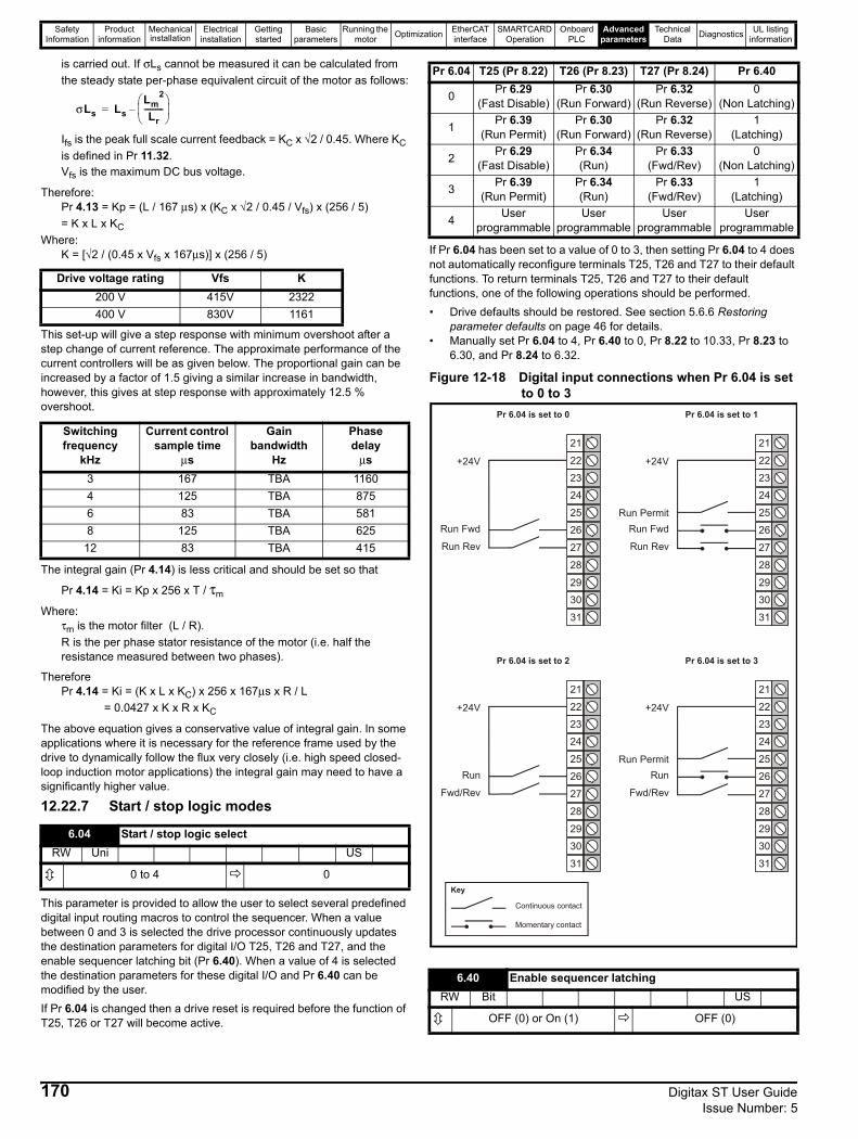
Safety Information
Product information
Mechanical installation
Electrical installation
Getting started
Basic parameters
Running the motor Optimization EtherCAT
interfaceSMARTCARD
OperationOnboard
PLCAdvanced
parametersTechnical
Data Diagnostics UL listing information
is carried out. If σLs cannot be measured it can be calculated from the steady state per-phase equivalent circuit of the motor as follows:
Ifs is the peak full scale current feedback = KC x √2 / 0.45. Where KC is defined in Pr 11.32.Vfs is the maximum DC bus voltage.
Therefore:Pr 4.13 = Kp = (L / 167 μs) x (KC x √2 / 0.45 / Vfs) x (256 / 5) = K x L x KC
Where:K = [√2 / (0.45 x Vfs x 167μs)] x (256 / 5)
This set-up will give a step response with minimum overshoot after a step change of current reference. The approximate performance of the current controllers will be as given below. The proportional gain can be increased by a factor of 1.5 giving a similar increase in bandwidth, however, this gives at step response with approximately 12.5 % overshoot.
The integral gain (Pr 4.14) is less critical and should be set so that
Pr 4.14 = Ki = Kp x 256 x T / τm
Where:τm is the motor filter (L / R). R is the per phase stator resistance of the motor (i.e. half the resistance measured between two phases).
ThereforePr 4.14 = Ki = (K x L x KC) x 256 x 167μs x R / L
= 0.0427 x K x R x KC
The above equation gives a conservative value of integral gain. In some applications where it is necessary for the reference frame used by the drive to dynamically follow the flux very closely (i.e. high speed closed-loop induction motor applications) the integral gain may need to have a significantly higher value.
12.22.7 Start / stop logic modes
This parameter is provided to allow the user to select several predefined digital input routing macros to control the sequencer. When a value between 0 and 3 is selected the drive processor continuously updates the destination parameters for digital I/O T25, T26 and T27, and the enable sequencer latching bit (Pr 6.40). When a value of 4 is selected the destination parameters for these digital I/O and Pr 6.40 can be modified by the user.If Pr 6.04 is changed then a drive reset is required before the function of T25, T26 or T27 will become active.
If Pr 6.04 has been set to a value of 0 to 3, then setting Pr 6.04 to 4 does not automatically reconfigure terminals T25, T26 and T27 to their default functions. To return terminals T25, T26 and T27 to their default functions, one of the following operations should be performed.• Drive defaults should be restored. See section 5.6.6 Restoring
parameter defaults on page 46 for details.• Manually set Pr 6.04 to 4, Pr 6.40 to 0, Pr 8.22 to 10.33, Pr 8.23 to
6.30, and Pr 8.24 to 6.32.
Figure 12-18 Digital input connections when Pr 6.04 is set to 0 to 3
Drive voltage rating Vfs K200 V 415V 2322400 V 830V 1161
Switching frequency
kHz
Current control sample time
μs
Gain bandwidth
Hz
Phase delay
μs3 167 TBA 11604 125 TBA 8756 83 TBA 5818 125 TBA 625
12 83 TBA 415
6.04 Start / stop logic selectRW Uni US
0 to 4 0
σLs LsLm
2
Lr----------⎝ ⎠⎜ ⎟⎛ ⎞
–=
Pr 6.04 T25 (Pr 8.22) T26 (Pr 8.23) T27 (Pr 8.24) Pr 6.40
0 Pr 6.29 (Fast Disable)
Pr 6.30 (Run Forward)
Pr 6.32 (Run Reverse)
0 (Non Latching)
1 Pr 6.39 (Run Permit)
Pr 6.30 (Run Forward)
Pr 6.32 (Run Reverse)
1 (Latching)
2 Pr 6.29 (Fast Disable)
Pr 6.34 (Run)
Pr 6.33 (Fwd/Rev)
0 (Non Latching)
3 Pr 6.39 (Run Permit)
Pr 6.34 (Run)
Pr 6.33 (Fwd/Rev)
1 (Latching)
4 User programmable
User programmable
User programmable
User programmable
6.40 Enable sequencer latchingRW Bit US
OFF (0) or On (1) OFF (0)
30
31
28
29
26
27
24
25
23
21
22+24V
Run Fwd
Run Rev
Pr 6.04 is set to 0
30
31
28
29
26
27
24
25
23
21
22+24V
Run Fwd
Run Rev
Pr 6.04 is set to 1
Run Permit
30
31
28
29
26
27
24
25
23
21
22+24V
Run
Fwd/Rev
Pr 6.04 is set to 2
30
31
28
29
26
27
24
25
23
21
22+24V
Run
Fwd/Rev
Pr 6.04 is set to 3
Run Permit
Momentary contact
Continuous contact
Key
170 Digitax ST User Guide Issue Number: 5
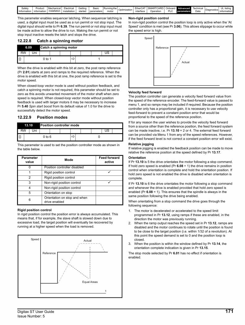
Safety Information
Product information
Mechanical installation
Electrical installation
Getting started
Basic parameters
Running the motor Optimization EtherCAT
interfaceSMARTCARD
OperationOnboard
PLCAdvanced
parametersTechnical
Data Diagnostics UL listing information
This parameter enables sequencer latching. When sequencer latching is used, a digital input must be used as a run permit or not stop input. The digital input should write to Pr 6.39. The run permit or not stop input must be made active to allow the drive to run. Making the run permit or not stop input inactive resets the latch and stops the drive.
12.22.8 Catch a spinning motor
When the drive is enabled with this bit at zero, the post ramp reference (Pr 2.01) starts at zero and ramps to the required reference. When the drive is enabled with this bit at one, the post ramp reference is set to the motor speed.When closed-loop vector mode is used without position feedback, and catch a spinning motor is not required, this parameter should be set to zero as this avoids unwanted movement of the motor shaft when zero speed is required. When closed-loop vector mode without position feedback is used with larger motors it may be necessary to increase Pr 5.40 Spin start boost from its default value of 1.0 for the drive to successfully detect the motor speed.
12.22.9 Position modes
This parameter is used to set the position controller mode as shown in the table below.
Rigid position controlIn rigid position control the position error is always accumulated. This means that, if for example, the slave shaft is slowed down due to excessive load, the target position will eventually be recovered by running at a higher speed when the load is removed.
Non-rigid position controlIn non-rigid position control the position loop is only active when the 'At Speed' condition is met (see Pr 3.06). This allows slippage to occur while the speed error is high.
Velocity feed forwardThe position controller can generate a velocity feed forward value from the speed of the reference encoder. The feed-forward value is passed to menu 1, and so ramps may be included if required. Because the position controller only has a proportional gain, it is necessary to use velocity feed-forward to prevent a constant position error that would be proportional to the speed of the reference position.If for any reason the user wishes to provide the velocity feed forward from a source other than the reference position, the feed forward system can be made inactive, i.e. Pr 13.10 = 2 or 4. The external feed forward can be provided via Menu 1 from any of the speed references. However, if the feed forward level is not correct a constant position error will exist.Relative joggingIf relative jogging is enabled the feedback position can be made to move relative the reference position at the speed defined by Pr 13.17.OrientationIf Pr 13.10 is 5 the drive orientates the motor following a stop command. If hold zero speed is enabled (Pr 6.08 = 1) the drive remains in position control when orientation is complete and hold the orientation position. If hold zero speed is not enabled the drive is disabled when orientation is complete. If Pr 13.10 is 6 the drive orientates the motor following a stop command and whenever the drive is enabled provided that hold zero speed is enabled (Pr 6.08 = 1). This ensures that the spindle is always in the same position following the drive being enabled.When orientating from a stop command the drive goes through the following sequence:1. The motor is decelerated or accelerated to the speed limit
programmed in Pr 13.12, using ramps if these are enabled, in the direction the motor was previously running.
2. When the ramp output reaches the speed set in Pr 13.12, ramps are disabled and the motor continues to rotate until the position is found to be close to the target position (i.e. within 1/32 of a revolution). At this point the speed demand is set to 0 and the position loop is closed.
3. When the position is within the window defined by Pr 13.14, the orientation complete indication is given in Pr 13.15.
The stop mode selected by Pr 6.01 has no effect if orientation is enabled.
6.09 Catch a spinning motorRW Uni US
0 to 1 1
13.10 Position controller modeRW Uni US
0 to 6 0
Parameter value Mode Feed forward
active0 Position controller disabled1 Rigid position control2 Rigid position control 3 Non-rigid position control 4 Non-rigid position control 5 Orientation on stop
6 Orientation on stop and when drive enabled
Reference
ActualSpeed
Equal Areas
t
Reference
Actual
Speed
Digitax ST User Guide 171Issue Number: 5
Safety Information
Product information
Mechanical installation
Electrical installation
Getting started
Basic parameters
Running the motor Optimization EtherCAT
interfaceSMARTCARD
OperationOnboard
PLCAdvanced
parametersTechnical
Data Diagnostics UL listing information
12.22.10 Fast Disable
This bit is a duplicate of parameter Pr 8.09 and reflects the state of the enable input. With software V01.10.00 and later, if the destination of one of the drive digital I/O (Pr 8.21 to Pr 8.26) is set to Pr 6.29 and the I/O is set as an input, the state of the input does not affect the value of this parameter as it is protected, however, it does provide a fast disable function. The Safe Torque Off input to the drive (T31) disables the drive in hardware by removing the gate drive signals from the inverter IGBTs and also disables the drive via the software system. When the drive is disabled by de-activating the Safe Torque Off input (T31) there can be a delay of up to 20 ms (typically 8 ms) before the drive is disabled. However, if a digital I/O is set up to provide the fast disable function it is possible to disable the drive within 600 μs of de-activating the input. To do this an enable signal should be given to both the Safe Torque Off input (T31) and to the digital I/O selected for the fast disable function. The state of the digital I/O including the effect of its associated invert parameter is ANDed with the Safe Torque Off (T31) to enable the drive.
6.29 Hardware enableRO Bit NC PT
OFF (0) or On (1)
If the safety function of the Safe Torque Off input is required then there must not be a direct connection between the Safe Torque Off input (T31) and any other digital I/O on the drive. If the safety function of the Safe Torque Off input and the fast disable function is required then the drive should be given two separate independent enable signals. A safety related enable from a safe source connected to the Safe Torque Off input on the drive. A second enable connected to the digital I/O on the drive selected for the fast disable function. The circuit must be arranged so that a fault which causes the fast input to be forced high cannot cause the Safe Torque Off input to be forced high, including the case where a component such as a blocking diode has failed.
WARNING
172 Digitax ST User Guide Issue Number: 5
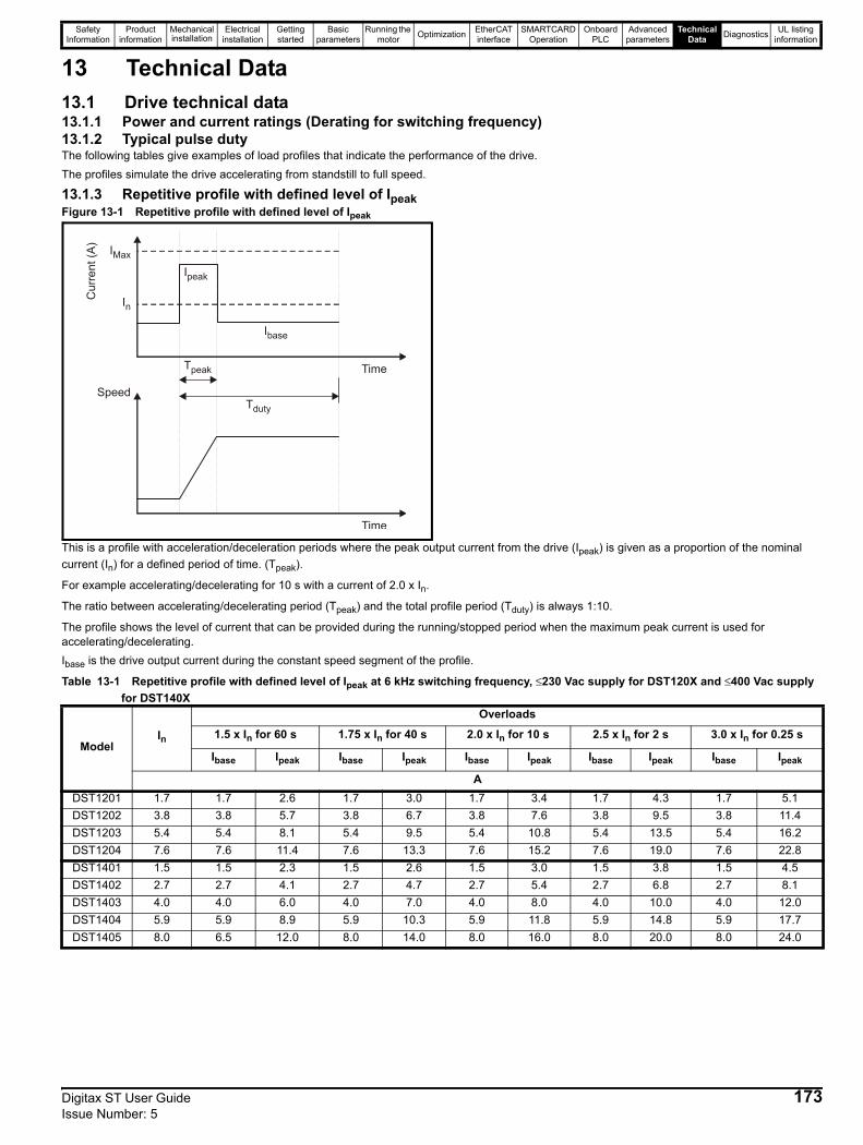
Safety Information
Product information
Mechanical installation
Electrical installation
Getting started
Basic parameters
Running the motor Optimization EtherCAT
interfaceSMARTCARD
OperationOnboard
PLCAdvanced
parametersTechnical
Data Diagnostics UL listing information
13 Technical Data13.1 Drive technical data13.1.1 Power and current ratings (Derating for switching frequency)13.1.2 Typical pulse dutyThe following tables give examples of load profiles that indicate the performance of the drive. The profiles simulate the drive accelerating from standstill to full speed.
13.1.3 Repetitive profile with defined level of IpeakFigure 13-1 Repetitive profile with defined level of Ipeak
This is a profile with acceleration/deceleration periods where the peak output current from the drive (Ipeak) is given as a proportion of the nominal current (In) for a defined period of time. (Tpeak).
For example accelerating/decelerating for 10 s with a current of 2.0 x In.
The ratio between accelerating/decelerating period (Tpeak) and the total profile period (Tduty) is always 1:10.
The profile shows the level of current that can be provided during the running/stopped period when the maximum peak current is used for accelerating/decelerating.Ibase is the drive output current during the constant speed segment of the profile.
Table 13-1 Repetitive profile with defined level of Ipeak at 6 kHz switching frequency, ≤230 Vac supply for DST120X and ≤400 Vac supply for DST140X
ModelIn
Overloads
1.5 x In for 60 s 1.75 x In for 40 s 2.0 x In for 10 s 2.5 x In for 2 s 3.0 x In for 0.25 s
Ibase Ipeak Ibase Ipeak Ibase Ipeak Ibase Ipeak Ibase Ipeak
ADST1201 1.7 1.7 2.6 1.7 3.0 1.7 3.4 1.7 4.3 1.7 5.1DST1202 3.8 3.8 5.7 3.8 6.7 3.8 7.6 3.8 9.5 3.8 11.4DST1203 5.4 5.4 8.1 5.4 9.5 5.4 10.8 5.4 13.5 5.4 16.2DST1204 7.6 7.6 11.4 7.6 13.3 7.6 15.2 7.6 19.0 7.6 22.8DST1401 1.5 1.5 2.3 1.5 2.6 1.5 3.0 1.5 3.8 1.5 4.5DST1402 2.7 2.7 4.1 2.7 4.7 2.7 5.4 2.7 6.8 2.7 8.1DST1403 4.0 4.0 6.0 4.0 7.0 4.0 8.0 4.0 10.0 4.0 12.0DST1404 5.9 5.9 8.9 5.9 10.3 5.9 11.8 5.9 14.8 5.9 17.7DST1405 8.0 6.5 12.0 8.0 14.0 8.0 16.0 8.0 20.0 8.0 24.0
Ipeak
Cur
rent
(A)
Tpeak
Tduty
IMax
In
Speed
Time
Time
Digitax ST User Guide 173Issue Number: 5
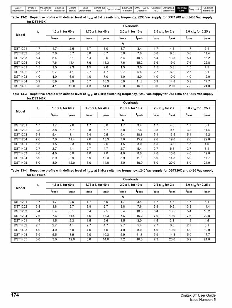
Safety Information
Product information
Mechanical installation
Electrical installation
Getting started
Basic parameters
Running the motor Optimization EtherCAT
interfaceSMARTCARD
OperationOnboard
PLCAdvanced
parametersTechnical
Data Diagnostics UL listing information
Table 13-2 Repetitive profile with defined level of Ipeak at 8kHz switching frequency, ≤230 Vac supply for DST120X and ≤400 Vac supply for DST140X
Table 13-3 Repetitive profile with defined level of Ipeak at 6 kHz switching frequency, ≤240 Vac supply for DST120X and ≤480 Vac supply for DST140X
Table 13-4 Repetitive profile with defined level of Ipeak at 8 kHz switching frequency, ≤240 Vac supply for DST120X and ≤480 Vac supply for DST140X
ModelIn
Overloads
1.5 x In for 60 s 1.75 x In for 40 s 2.0 x In for 10 s 2.5 x In for 2 s 3.0 x In for 0.25 s
Ibase Ipeak Ibase Ipeak Ibase Ipeak Ibase Ipeak Ibase Ipeak
ADST1201 1.7 1.7 2.6 1.7 3.0 1.7 3.4 1.7 4.3 1.7 5.1DST1202 3.8 3.8 5.7 3.8 6.7 3.8 7.6 3.8 9.5 3.8 11.4DST1203 5.4 5.4 8.1 5.4 9.5 5.4 10.8 5.4 13.5 5.4 16.2DST1204 7.6 7.6 11.4 7.6 13.3 7.6 15.2 7.6 19.0 7.6 22.8DST1401 1.5 1.5 2.3 1.5 2.6 1.5 3.0 1.5 3.8 1.5 4.5DST1402 2.7 2.7 4.1 2.7 4.7 2.7 5.4 2.7 6.8 2.7 8.1DST1403 4.0 4.0 6.0 4.0 7.0 4.0 8.0 4.0 10.0 4.0 12.0DST1404 5.9 5.9 8.9 5.7 10.3 5.9 11.8 5.9 14.8 5.9 17.7DST1405 8.0 4.1 12.0 4.3 14.0 8.0 16.0 8.0 20.0 7.8 24.0
ModelIn
Overloads
1.5 x In for 60 s 1.75 x In for 40 s 2.0 x In for 10 s 2.5 x In for 2 s 3.0 x In for 0.25 s
Ibase Ipeak Ibase Ipeak Ibase Ipeak Ibase Ipeak Ibase Ipeak
ADST1201 1.7 1.7 2.6 1.7 3.0 1.7 3.4 1.7 4.3 1.7 5.1DST1202 3.8 3.8 5.7 3.8 6.7 3.8 7.6 3.8 9.5 3.8 11.4DST1203 5.4 5.4 8.1 5.4 9.5 5.4 10.8 5.4 13.5 5.4 16.2DST1204 7.6 7.6 11.4 7.6 13.3 7.6 15.2 7.6 19.0 7.6 22.8DST1401 1.5 1.5 2.3 1.5 2.6 1.5 3.0 1.5 3.8 1.5 4.5DST1402 2.7 2.7 4.1 2.7 4.7 2.7 5.4 2.7 6.8 2.7 8.1DST1403 4.0 4.0 6.0 4.0 7.0 4.0 8.0 4.0 10.0 4.0 12.0DST1404 5.9 5.9 8.9 5.9 10.3 5.9 11.8 5.9 14.8 5.9 17.7DST1405 8.0 8.0 12.0 8.0 14.0 8.0 16.0 8.0 20.0 8.0 24.0
ModelIn
Overloads
1.5 x In for 60 s 1.75 x In for 40 s 2.0 x In for 10 s 2.5 x In for 2 s 3.0 x In for 0.25 s
Ibase Ipeak Ibase Ipeak Ibase Ipeak Ibase Ipeak Ibase Ipeak
ADST1201 1.7 1.7 2.6 1.7 3.0 1.7 3.4 1.7 4.3 1.7 5.1DST1202 3.8 3.8 5.7 3.8 6.7 3.8 7.6 3.8 9.5 3.8 11.4DST1203 5.4 5.4 8.1 5.4 9.5 5.4 10.8 5.4 13.5 5.4 16.2DST1204 7.6 7.6 11.4 7.6 13.3 7.6 15.2 7.6 19.0 7.6 22.8DST1401 1.5 1.5 2.3 1.5 2.6 1.5 3.0 1.5 3.8 1.5 4.5DST1402 2.7 2.7 4.1 2.7 4.7 2.7 5.4 2.7 6.8 2.7 8.1DST1403 4.0 4.0 6.0 4.0 7.0 4.0 8.0 4.0 10.0 4.0 12.0DST1404 5.9 5.5 8.9 5.0 10.3 5.9 11.8 5.9 14.8 5.9 17.7DST1405 8.0 3.6 12.0 3.8 14.0 7.2 16.0 7.3 20.0 6.9 24.0
174 Digitax ST User Guide Issue Number: 5

Safety Information
Product information
Mechanical installation
Electrical installation
Getting started
Basic parameters
Running the motor Optimization EtherCAT
interfaceSMARTCARD
OperationOnboard
PLCAdvanced
parametersTechnical
Data Diagnostics UL listing information
13.1.4 Repetitive profile with defined ratio between Ibase to IpeakFigure 13-2 Repetitive profile with defined ratio between Ibase to Ipeak
This is a profile with acceleration/deceleration periods where the peak output current from the drive (Ipeak) is given as a proportion of the base current (Ibase) for a defined period of time. (Tpeak).
For example accelerating/decelerating for 10 s with a current of 2.0 x Ibase.
The ratio between accelerating/decelerating period (Tpeak) and the total profile period (Tduty) is always 1:10.
The profile shows the highest Ibase ratings possible for the given Ipeak/Ibase ratio.
Table 13-5 Repetitive profile with defined ratio between Ibase to Ipeak at 6 kHz switching frequency, ≤230 Vac supply for DST120X and ≤400 Vac supply for DST140X
Table 13-6 Repetitive profile with defined ratio between Ibase to Ipeak at 8 kHz switching frequency, ≤230 Vac supply for DST120X and ≤400 Vac supply for DST140X
ModelIn
Overloads
1.5 x Ibase for 60 s 1.75 x Ibase for 40 s 2.0 x Ibase for 10 s 2.5 x Ibase for 2 s 3.0 x Ibase for 0.25 s
Ibase Ipeak Ibase Ipeak Ibase Ipeak Ibase Ipeak Ibase Ipeak
ADST1201 1.7 1.7 2.6 1.7 3.0 1.7 3.4 1.7 4.3 1.7 5.1DST1202 3.8 3.8 5.7 3.8 6.7 3.8 7.6 3.8 9.5 3.8 11.4DST1203 5.4 5.4 8.1 5.4 9.5 5.4 10.8 5.4 13.5 5.4 16.2DST1204 7.6 7.6 11.4 7.6 13.3 7.6 15.2 7.6 19.0 7.6 22.8DST1401 1.5 1.5 2.3 1.5 2.6 1.5 3.0 1.5 3.8 1.5 4.5DST1402 2.7 2.7 4.1 2.7 4.7 2.7 5.4 2.7 6.8 2.7 8.1DST1403 4.0 4.0 6.0 4.0 7.0 4.0 8.0 4.0 10.0 4.0 12.0DST1404 5.9 5.9 8.9 5.9 10.3 5.9 11.8 5.9 14.8 5.9 17.7DST1405 8.0 8.0 12.0 8.0 14.0 8.0 16.0 8.0 20.0 8.0 24.0
ModelIn
Overloads
1.5 x Ibase for 60 s 1.75 x Ibase for 40 s 2.0 x Ibase for 10 s 2.5 x Ibase for 2 s 3.0 x Ibase for 0.25 s
Ibase Ipeak Ibase Ipeak Ibase Ipeak Ibase Ipeak Ibase Ipeak
ADST1201 1.7 1.7 2.6 1.7 3.0 1.7 3.4 1.7 4.3 1.7 5.1DST1202 3.8 3.8 5.7 3.8 6.7 3.8 7.6 3.8 9.5 3.8 11.4DST1203 5.4 5.4 8.1 5.4 9.5 5.4 10.8 5.4 13.5 5.4 16.2DST1204 7.6 7.6 11.4 7.6 13.3 7.6 15.2 7.6 19.0 7.6 22.8DST1401 1.5 1.5 2.3 1.5 2.6 1.5 3.0 1.5 3.8 1.5 4.5DST1402 2.7 2.7 4.1 2.7 4.7 2.7 5.4 2.7 6.8 2.7 8.1DST1403 4.0 4.0 6.0 4.0 7.0 4.0 8.0 4.0 10.0 4.0 12.0DST1404 5.9 5.9 8.9 5.9 10.3 5.9 11.8 5.9 14.8 5.9 17.7DST1405 8.0 7.2 10.8 7.2 12.6 8.0 16.0 8.0 20.0 8.0 24.0
Ipeak
Cur
rent
(A)
Tpeak
Tduty
IMax
Speed
Time
Time
Digitax ST User Guide 175Issue Number: 5

Safety Information
Product information
Mechanical installation
Electrical installation
Getting started
Basic parameters
Running the motor Optimization EtherCAT
interfaceSMARTCARD
OperationOnboard
PLCAdvanced
parametersTechnical
Data Diagnostics UL listing information
Table 13-7 Repetitive profile with defined ratio between Ibase to Ipeak at 6 kHz switching frequency, ≤240 Vac supply for DST120X and ≤480 Vac supply for DST140X
Table 13-8 Repetitive profile with defined ratio between Ibase to Ipeak at 8 kHz switching frequency, ≤240 Vac supply for DST120X and ≤480 Vac supply for DST140X
13.1.5 Continuous ratingTable 13-9 Continuous rating with no overload, ≤230 Vac supply
for DST120X and ≤400 Vac supply for DST140XTable 13-10 Continuous rating with no overload, ≤240 Vac supply
for DST120X and ≤480 Vac supply for DST140X
The power available from a rectifier may limit these figures.The drive will automatically reduce the output switching frequency so that the highest possible output current can be supported without a thermal trip. This allows the drive to support the highest possible current at standstill while operating at a higher switching frequency under normal running conditions.This feature can be disabled using drive Pr 5.35, see the Advanced User Guide for further details.
ModelIn
Overloads
1.5 x Ibase for 60 s 1.75 x Ibase for 40 s 2.0 x Ibase for 10 s 2.5 x Ibase for 2 s 3.0 x Ibase for 0.25 s
Ibase Ipeak Ibase Ipeak Ibase Ipeak Ibase Ipeak Ibase Ipeak
ADST1201 1.7 1.7 2.6 1.7 3.0 1.7 3.4 1.7 4.3 1.7 5.1DST1202 3.8 3.8 5.7 3.8 6.7 3.8 7.6 3.8 9.5 3.8 11.4DST1203 5.4 5.4 8.1 5.4 9.5 5.4 10.8 5.4 13.5 5.4 16.2DST1204 7.6 7.6 11.4 7.6 13.3 7.6 15.2 7.6 19.0 7.6 22.8DST1401 1.5 1.5 2.3 1.5 2.6 1.5 3.0 1.5 3.8 1.5 4.5DST1402 2.7 2.7 4.1 2.7 4.7 2.7 5.4 2.7 6.8 2.7 8.1DST1403 4.0 4.0 6.0 4.0 7.0 4.0 8.0 4.0 10.0 4.0 12.0DST1404 5.9 5.9 8.9 5.9 10.3 5.9 11.8 5.9 14.8 5.9 17.7DST1405 8.0 8.0 12.0 8.0 14.0 8.0 16.0 8.0 20.0 8.0 24.0
ModelIn
Overloads
1.5 x Ibase for 60 s 1.75 x Ibase for 40 s 2.0 x Ibase for 10 s 2.5 x Ibase for 2 s 3.0 x Ibase for 0.25 s
Ibase Ipeak Ibase Ipeak Ibase Ipeak Ibase Ipeak Ibase Ipeak
ADST1201 1.7 1.7 2.6 1.7 3.0 1.7 3.4 1.7 4.3 1.7 5.1DST1202 3.8 3.8 5.7 3.8 6.7 3.8 7.6 3.8 9.5 3.8 11.4DST1203 5.4 5.4 8.1 5.4 9.5 5.4 10.8 5.4 13.5 5.4 16.2DST1204 7.6 7.6 11.4 7.6 13.3 7.6 15.2 7.6 19.0 7.6 22.8DST1401 1.5 1.5 2.3 1.5 2.6 1.5 3.0 1.5 3.8 1.5 4.5DST1402 2.7 2.7 4.1 2.7 4.7 2.7 5.4 2.7 6.8 2.7 8.1DST1403 4.0 4.0 6.0 4.0 7.0 4.0 8.0 4.0 10.0 4.0 12.0DST1404 5.9 5.9 8.9 5.6 9.8 5.9 11.8 5.9 14.8 5.9 17.7DST1405 8.0 7.2 10.8 6.8 11.9 7.6 15.2 7.6 19.0 7.6 22.8
ModelIn
6kHz 8kHz 12kHz
Icont at 150 Hz
Icont at 0 Hz
Icont at 150 Hz
Icont at 0 Hz
Icont at 150 Hz
Icont at 0 Hz
ADST1201 1.7 1.7DST1202 3.8 3.8DST1203 5.4 5.4DST1204 7.6 7.6DST1401 1.5 1.5DST1402 2.7 2.7DST1403 4.0 4.0DST1404 5.9 5.9 4.2DST1405 8.0 8.0 7.0 7.9 5.0
ModelIn
6kHz 8kHz 12kHz
Icont at 150 Hz
Icont at 0 Hz
Icont at 150 Hz
Icont at 0 Hz
Icont at 150 Hz
Icont at 0 Hz
ADST1201 1.7 1.7DST1202 3.8 3.8DST1203 5.4 5.4DST1204 7.6 7.6DST1401 1.5 1.5DST1402 2.7 2.7DST1403 4.0 4.0 3.4DST1404 5.9 5.9 5.4 3.4DST1405 8.0 8.0 7.5 8.0 6.2 6.4 4.0
NOTE
176 Digitax ST User Guide Issue Number: 5
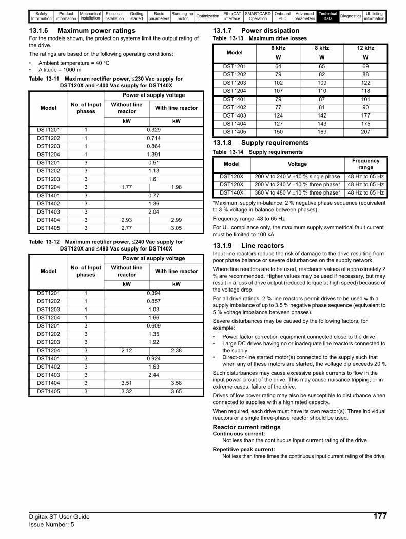
Safety Information
Product information
Mechanical installation
Electrical installation
Getting started
Basic parameters
Running the motor Optimization EtherCAT
interfaceSMARTCARD
OperationOnboard
PLCAdvanced
parametersTechnical
Data Diagnostics UL listing information
13.1.6 Maximum power ratings For the models shown, the protection systems limit the output rating of the drive. The ratings are based on the following operating conditions:• Ambient temperature = 40 °C• Altitude = 1000 mTable 13-11 Maximum rectifier power, ≤230 Vac supply for
DST120X and ≤400 Vac supply for DST140X
Table 13-12 Maximum rectifier power, ≤240 Vac supply for DST120X and ≤480 Vac supply for DST140X
13.1.7 Power dissipationTable 13-13 Maximum drive losses
13.1.8 Supply requirementsTable 13-14 Supply requirements
*Maximum supply in-balance: 2 % negative phase sequence (equivalent to 3 % voltage in-balance between phases).Frequency range: 48 to 65 HzFor UL compliance only, the maximum supply symmetrical fault current must be limited to 100 kA
13.1.9 Line reactorsInput line reactors reduce the risk of damage to the drive resulting from poor phase balance or severe disturbances on the supply network.Where line reactors are to be used, reactance values of approximately 2 % are recommended. Higher values may be used if necessary, but may result in a loss of drive output (reduced torque at high speed) because of the voltage drop.For all drive ratings, 2 % line reactors permit drives to be used with a supply imbalance of up to 3.5 % negative phase sequence (equivalent to 5 % voltage imbalance between phases).Severe disturbances may be caused by the following factors, for example:• Power factor correction equipment connected close to the drive• Large DC drives having no or inadequate line reactors connected to
the supply• Direct-on-line started motor(s) connected to the supply such that
when any of these motors are started, the voltage dip exceeds 20 %Such disturbances may cause excessive peak currents to flow in the input power circuit of the drive. This may cause nuisance tripping, or in extreme cases, failure of the drive.Drives of low power rating may also be susceptible to disturbance when connected to supplies with a high rated capacity.When required, each drive must have its own reactor(s). Three individual reactors or a single three-phase reactor should be used.
Reactor current ratingsContinuous current:
Not less than the continuous input current rating of the drive.Repetitive peak current:
Not less than three times the continuous input current rating of the drive.
Model No. of Input phases
Power at supply voltage
Without line reactor With line reactor
kW kWDST1201 1 0.329DST1202 1 0.714DST1203 1 0.864DST1204 1 1.391DST1201 3 0.51DST1202 3 1.13DST1203 3 1.61DST1204 3 1.77 1.98DST1401 3 0.77DST1402 3 1.36DST1403 3 2.04DST1404 3 2.93 2.99DST1405 3 2.77 3.05
Model No. of Input phases
Power at supply voltage
Without line reactor With line reactor
kW kWDST1201 1 0.394DST1202 1 0.857DST1203 1 1.03DST1204 1 1.66DST1201 3 0.609DST1202 3 1.35DST1203 3 1.92DST1204 3 2.12 2.38DST1401 3 0.924DST1402 3 1.63DST1403 3 2.44DST1404 3 3.51 3.58DST1405 3 3.32 3.65
Model6 kHz 8 kHz 12 kHz
W W WDST1201 64 65 69DST1202 79 82 88DST1203 102 109 122DST1204 107 110 118DST1401 79 87 101DST1402 77 81 90DST1403 124 142 177DST1404 127 143 175DST1405 150 169 207
Model Voltage Frequency range
DST120X 200 V to 240 V ±10 % single phase 48 Hz to 65 HzDST120X 200 V to 240 V ±10 % three phase* 48 Hz to 65 HzDST140X 380 V to 480 V ±10 % three phase* 48 Hz to 65 Hz
Digitax ST User Guide 177Issue Number: 5
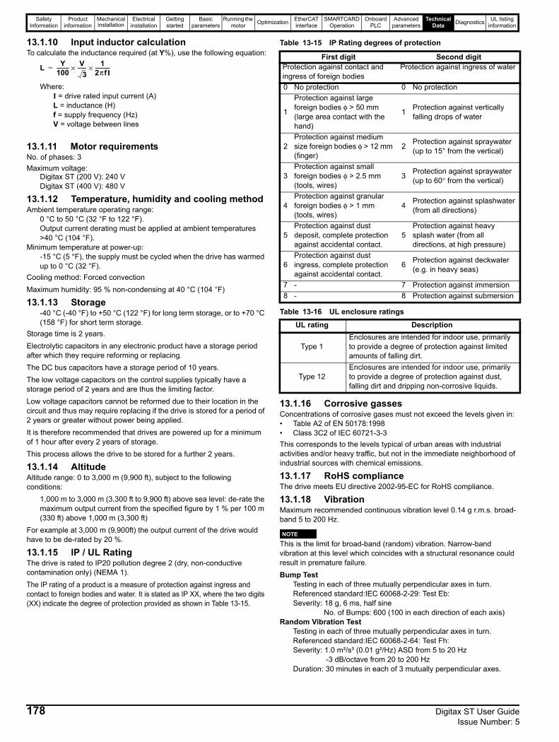
Safety Information
Product information
Mechanical installation
Electrical installation
Getting started
Basic parameters
Running the motor Optimization EtherCAT
interfaceSMARTCARD
OperationOnboard
PLCAdvanced
parametersTechnical
Data Diagnostics UL listing information
13.1.10 Input inductor calculationTo calculate the inductance required (at Y%), use the following equation:
Where:I = drive rated input current (A)L = inductance (H)f = supply frequency (Hz)V = voltage between lines
13.1.11 Motor requirementsNo. of phases: 3Maximum voltage:
Digitax ST (200 V): 240 VDigitax ST (400 V): 480 V
13.1.12 Temperature, humidity and cooling methodAmbient temperature operating range:
0 °C to 50 °C (32 °F to 122 °F). Output current derating must be applied at ambient temperatures >40 °C (104 °F).
Minimum temperature at power-up: -15 °C (5 °F), the supply must be cycled when the drive has warmed up to 0 °C (32 °F).
Cooling method: Forced convectionMaximum humidity: 95 % non-condensing at 40 °C (104 °F)
13.1.13 Storage-40 °C (-40 °F) to +50 °C (122 °F) for long term storage, or to +70 °C (158 °F) for short term storage.
Storage time is 2 years. Electrolytic capacitors in any electronic product have a storage period after which they require reforming or replacing. The DC bus capacitors have a storage period of 10 years.The low voltage capacitors on the control supplies typically have a storage period of 2 years and are thus the limiting factor.Low voltage capacitors cannot be reformed due to their location in the circuit and thus may require replacing if the drive is stored for a period of 2 years or greater without power being applied.It is therefore recommended that drives are powered up for a minimum of 1 hour after every 2 years of storage.This process allows the drive to be stored for a further 2 years.
13.1.14 AltitudeAltitude range: 0 to 3,000 m (9,900 ft), subject to the following conditions:
1,000 m to 3,000 m (3,300 ft to 9,900 ft) above sea level: de-rate the maximum output current from the specified figure by 1 % per 100 m (330 ft) above 1,000 m (3,300 ft)
For example at 3,000 m (9,900ft) the output current of the drive would have to be de-rated by 20 %.
13.1.15 IP / UL RatingThe drive is rated to IP20 pollution degree 2 (dry, non-conductive contamination only) (NEMA 1). The IP rating of a product is a measure of protection against ingress and contact to foreign bodies and water. It is stated as IP XX, where the two digits (XX) indicate the degree of protection provided as shown in Table 13-15.
Table 13-15 IP Rating degrees of protection
Table 13-16 UL enclosure ratings
13.1.16 Corrosive gassesConcentrations of corrosive gases must not exceed the levels given in:• Table A2 of EN 50178:1998• Class 3C2 of IEC 60721-3-3This corresponds to the levels typical of urban areas with industrial activities and/or heavy traffic, but not in the immediate neighborhood of industrial sources with chemical emissions.
13.1.17 RoHS complianceThe drive meets EU directive 2002-95-EC for RoHS compliance.
13.1.18 VibrationMaximum recommended continuous vibration level 0.14 g r.m.s. broad-band 5 to 200 Hz.
This is the limit for broad-band (random) vibration. Narrow-band vibration at this level which coincides with a structural resonance could result in premature failure.Bump Test
Testing in each of three mutually perpendicular axes in turn.Referenced standard:IEC 60068-2-29: Test Eb:Severity: 18 g, 6 ms, half sine
No. of Bumps: 600 (100 in each direction of each axis)Random Vibration Test
Testing in each of three mutually perpendicular axes in turn.Referenced standard:IEC 60068-2-64: Test Fh:Severity: 1.0 m²/s³ (0.01 g²/Hz) ASD from 5 to 20 Hz
-3 dB/octave from 20 to 200 HzDuration: 30 minutes in each of 3 mutually perpendicular axes.
L Y100---------- V
3-------× 1
2πfI------------×=
First digit Second digitProtection against contact and ingress of foreign bodies
Protection against ingress of water
0 No protection 0 No protection
1
Protection against large foreign bodies φ > 50 mm (large area contact with the hand)
1 Protection against vertically falling drops of water
2Protection against medium size foreign bodies φ > 12 mm (finger)
2 Protection against spraywater (up to 15° from the vertical)
3Protection against small foreign bodies φ > 2.5 mm (tools, wires)
3 Protection against spraywater (up to 60° from the vertical)
4Protection against granular foreign bodies φ > 1 mm (tools, wires)
4 Protection against splashwater (from all directions)
5Protection against dust deposit, complete protection against accidental contact.
5Protection against heavy splash water (from all directions, at high pressure)
6Protection against dust ingress, complete protection against accidental contact.
6 Protection against deckwater (e.g. in heavy seas)
7 - 7 Protection against immersion8 - 8 Protection against submersion
UL rating Description
Type 1Enclosures are intended for indoor use, primarily to provide a degree of protection against limited amounts of falling dirt.
Type 12Enclosures are intended for indoor use, primarily to provide a degree of protection against dust, falling dirt and dripping non-corrosive liquids.
NOTE
178 Digitax ST User Guide Issue Number: 5
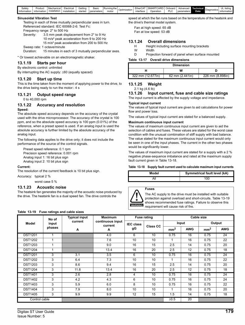
Safety Information
Product information
Mechanical installation
Electrical installation
Getting started
Basic parameters
Running the motor Optimization EtherCAT
interfaceSMARTCARD
OperationOnboard
PLCAdvanced
parametersTechnical
Data Diagnostics UL listing information
Sinusoidal Vibration Test Testing in each of three mutually perpendicular axes in turn.Referenced standard: IEC 60068-2-6: Test Fc:Frequency range: 2* to 500 HzSeverity: 3.5 mm peak displacement from 2* to 9 Hz
10 m/s² peak acceleration from 9 to 200 Hz 15 m/s² peak acceleration from 200 to 500 Hz
Sweep rate: 1 octave/minuteDuration: 15 minutes in each of 3 mutually perpendicular axes.
* Or lowest achievable on an electromagnetic shaker.
13.1.19 Starts per hourBy electronic control: unlimitedBy interrupting the AC supply: ≤60 (equally spaced)
13.1.20 Start up timeThis is the time taken from the moment of applying power to the drive, to the drive being ready to run the motor:: 4 s
13.1.21 Output speed range0 to 40,000 rpm
13.1.22 Accuracy and resolutionSpeed:The absolute speed accuracy depends on the accuracy of the crystal used with the drive microprocessor. The accuracy of the crystal is 100 ppm, and so the absolute speed accuracy is 100 ppm (0.01%) of the reference, when a preset speed is used. If an analog input is used the absolute accuracy is further limited by the absolute accuracy of the analog input.The following data applies to the drive only; it does not include the performance of the source of the control signals.
Preset speed reference: 0.1 rpmPrecision speed reference: 0.001 rpmAnalog input 1: 16 bit plus signAnalog input 2: 10 bit plus sign
Current:The resolution of the current feedback is 10 bit plus sign. Accuracy: typical 2 %
worst case 5 %
13.1.23 Acoustic noiseThe heatsink fan generates the majority of the acoustic noise produced by the drive. The heatsink fan is a dual speed fan. The drive controls the
speed at which the fan runs based on the temperature of the heatsink and the drive's thermal model system.
Fan at high speed: 65 dBFan at low speed: 53 dB
13.1.24 Overall dimensionsH Height including surface mounting bracketsW WidthD Projection forward of panel when surface mounted
Table 13-17 Overall drive dimensions
13.1.25 Weight2.1 kg (4.6 Ib)
13.1.26 Input current, fuse and cable size ratingsThe input current is affected by the supply voltage and impedance.Typical input currentThe values of typical input current are given to aid calculations for power flow and power loss.The values of typical input current are stated for a balanced supply.Maximum continuous input currentThe values of maximum continuous input current are given to aid the selection of cables and fuses. These values are stated for the worst case condition with the unusual combination of stiff supply with bad balance. The value stated for the maximum continuous input current would only be seen in one of the input phases. The current in the other two phases would be significantly lower.The values of maximum input current are stated for a supply with a 2 % negative phase-sequence imbalance and rated at the maximum supply fault current given in Table 13-18.
Table 13-18 Supply fault current used to calculate maximum input currents
Table 13-19 Fuse ratings and cable sizes
DimensionH W D
322 mm (12.677in) 62 mm (2.441in) 226 mm (8.898in)
Model Symmetrical fault level (kA)All 100
FusesThe AC supply to the drive must be installed with suitable protection against overload and short-circuits. Table 13-19 shows recommended fuse ratings. Failure to observe this requirement will cause risk of fire.WARNING
ModelNo of input
phases
Typical input current
A
Maximum continuous input
currentA
Fuse rating Cable size
IEC class gG Class CC
Input Output
mm2 AWG mm2 AWG
DST1201 1 4.0 6 10 0.75 16 0.75 24DST1202 1 7.6 10 10 1 16 0.75 22DST1203 1 9.0 16 15 2.5 14 0.75 20DST1204 1 13.4 16 20 2.5 12 0.75 18DST1201 3 3.1 3.5 6 10 0.75 16 0.75 24DST1202 3 6.4 7.3 10 10 1 16 0.75 22DST1203 3 8.6 9.4 16 15 2.5 14 0.75 20DST1204 3 11.8 13.4 16 20 2.5 12 0.75 18DST1401 3 2.6 2.8 4 10 0.75 16 0.75 24DST1402 3 4.2 4.3 6 10 0.75 16 0.75 24DST1403 3 5.9 6.0 8 10 0.75 16 0.75 22DST1404 3 7.9 8.0 10 10 1 16 0.75 20DST1405 3 9.9 9.9 12 15 1.5 14 0.75 18
Control cable ≥0.5 20
Digitax ST User Guide 179Issue Number: 5

Safety Information
Product information
Mechanical installation
Electrical installation
Getting started
Basic parameters
Running the motor Optimization EtherCAT
interfaceSMARTCARD
OperationOnboard
PLCAdvanced
parametersTechnical
Data Diagnostics UL listing information
PVC insulated cable should be used.Installation class (ref: IEC60364-5-52:2001)B1 - Separate cables in conduit.B2 - Multicore cable in conduitC - Multicore cable in free air.
Cable sizes are from IEC60364-5-52:2001 table A.52.C with correction factor for 40 °C ambient of 0.87 (from table A52.14) for cable installation method B2 (multicore cable in conduit).Cable size may be reduced if a different installation method is used, or if the ambient temperature is lower.The recommended cable sizes above are only a guide. The mounting and grouping of cables affects their current-carrying capacity, in some cases smaller cables may be acceptable but in other cases a larger cable is required to avoid excessive temperature or voltage drop. Refer to local wiring regulations for the correct size of cables.
NThe recommended output cable sizes assume that the motor maximum current matches that of the drive. Where a motor of reduced rating is used the cable rating may be chosen to match that of the motor. To ensure that the motor and cable are protected against overload, the drive must be programmed with the correct motor rated current.
NUL listing is dependent on the use of the correct type of UL-listed fuse, and applies when symmetrical short-circuit current does not exceed 100 kA. See Chapter 15 UL listing information on page 204 for sizing information.
An MCB (miniature circuit breaker) may be used in place of fuses under the following conditions:• The fault-clearing capacity must be sufficient for the installation• The I2T rating of the MCB must be less than or equal to that of the fuse
rating listed above.A fuse or other protection must be included in all live connections to the AC supply.For a parallel DC bus system the maximum AC input fusing is shown in Table 13-20 below.
Table 13-20 Maximum AC input fusing
Refer to the supplier of your drive for further information regarding DC bus paralleling.Inrush currentThe drive will have an inrush current during power-up, the peak inrush is limited to the value shown below:DST120X 18 A peakDST140X 35 A peak
The inrush current for all drives after a brown-out can be larger than the power-up inrush.
13.1.27 Motor cable size and maximum lengthsSince capacitance in the motor cable causes loading on the output of the drive, ensure the cable length does not exceed the values given in Table 13-21.Use 105 °C (221 °F) (UL 60/75 °C temp rise) PVC-insulated cable with copper conductors having a suitable voltage rating, for the following
power connections:• AC supply to external EMC filter (when used)• AC supply (or external EMC filter) to drive• Drive to motor• Drive to braking resistor• When operating in ambient >45 °C UL 75 °C cable should be used.Cable sizes are given for guidance only and may be changed depending on the application and the method of installation of the cables.The mounting and grouping of cables affect their current capacity, in some cases a larger cable is required to avoid excessive temperature or voltage drop.Input cable sizes should generally be regarded as a minimum, since they have been selected for co-ordination with the recommended fuses.Output cable sizes assume that the maximum motor current matches that of the drive.Where a motor of reduced rating is used the cable rating may be chosen to match that of the motor.To ensure that the motor and cable are protected against overload, the drive must be programmed with the correct motor rated current.• Cable lengths in excess of the specified values may be used only
when special techniques are adopted; refer to the supplier of the drive.
• The default switching frequency is 6 kHz.The drive power terminals are designed for a maximum cable size of 4.0mm2 (minimum 0.2mm / 24 AWG).Where more than one cable per terminal is used the combined diameters should not exceed the maximum. The terminals are suitable for both solid and stranded wires.
Table 13-21 Motor cable size and maximum lengths
13.1.28 Braking resistor valuesTable 13-22 Minimum resistance and power ratings
* Resistor tolerance: ±10 %
Model
Fuse ratingIEC class gG
Fuse ratingclass CC Input cable size
A Amm2 AWG
All 20 20 4.0 12
NOTE
NOTE
NOTE
NOTE
NOTE
NOTE
ModelOutput cable 6kHz 8kHz 12kHz
mm2 AWG m m m
DST1201
0.75
24
50
DST1202 22DST1203 20DST1204 18DST1401
24DST1402DST1403 22DST1404 20DST1405 18
ModelMinimum
resistance*
Peak power rating
Continuous power rating
Average power for
0.25s
Ω kW kW kWDST1201
23 6.60.5 1.6
DST1202 1.2 3.5DST1203 1.6 4.9DST1204 16 9.3 2.3 7.0DST1401
111 5.50.8 2.3
DST1402 1.4 4.1DST1403 75 8.1 2.0 6.1DST1404
28 21.73.0 9.0
DST1405 4.1 12.2
180 Digitax ST User Guide Issue Number: 5

Safety Information
Product information
Mechanical installation
Electrical installation
Getting started
Basic parameters
Running the motor Optimization EtherCAT
interfaceSMARTCARD
OperationOnboard
PLCAdvanced
parametersTechnical
Data Diagnostics UL listing information
13.1.29 Terminal torque settingsTable 13-23 Torque settings
*Torque tolerance = 10 %
Table 13-24 Plug-in terminal block maximum cable sizes
13.1.30 Electromagnetic compatibility (EMC)This is a summary of the EMC performance of the drive. For full details, refer to the EMC Data Sheet which can be obtained from the supplier of the drive.
Table 13-25 Immunity compliance
EmissionThe drive contains an in-built filter for basic emission control. An additional optional external filter provides further reduction of emission.
The requirements of the following standards are met, depending on the motor cable length and switching frequency.Table 13-26 DST120X (200 V) emission compliance (single and
three phase drives
Table 13-27 DST140X (400 V) emission compliance
Key to Table 13-26 and Table 13-27(shown in decreasing order of permitted emission level):E2R EN 61800-3:2004 second environment, restricted distribution (Additional measures may be required to prevent interference)E2U EN 61800-3:2004 second environment, unrestricted distributionI Industrial generic standard EN 61000-6-4:2007
EN 61800-3:2004 first environment restricted distribution (The following caution is required by EN 61800-3:2004)
R Residential generic standard EN 61000-6-3:2007EN 61800-3:2004 first environment unrestricted distribution
EN 61800-3:2004 defines the following:• The first environment is one that includes residential premises. It
also includes properties directly connected without intermediate transformers to a low-voltage power supply network which supplies buildings used for residential purposes.
• The second environment is one that includes all establishments other than those directly connected to a low-voltage power supply network which supplies buildings used for residential purposes.
Restricted distribution is defined as a mode of sales distribution in which the manufacturer restricts the supply of equipment to suppliers, customers or users who separately or jointly have technical competence in the EMC requirements of the application of drives.
Terminals Torque setting*Power terminals 1.0 N m (12.1 lb in)Control terminals 0.2 N m (1.7 lb in)
Status relay terminals 0.5 N m (4.5 lb in)Ground terminals 4 N m (35 lb in)
Small ground terminal screws 2 N m (17.7 lb in)
Model size Terminal block description Max cable size
All 11 way control connectors 1.5 mm2 (16 AWG)All 2 way relay connector 2.5 mm2 (12 AWG)
Standard Type of immunity Test specification Application Level
IEC61000-4-2 EN61000-4-2
Electrostatic discharge
6 kV contact discharge8 kV air discharge
Module enclosure
Level 3(industrial)
IEC61000-4-3EN61000-4-3
Radio frequency radiated field
10V/m prior to modulation80 - 1000 MHz80 % AM (1 kHz) modulation
Module enclosure
Level 3(industrial)
IEC61000-4-4EN61000-4-4
Fast transient burst
5/50 ns 2 kV transient at 5 kHz repetition frequency via coupling clamp
Control linesLevel 4(industrial harsh)
5/50 ns 2 kV transient at 5 kHz repetition frequency by direct injection
Power lines Level 3(industrial)
IEC61000-4-5EN61000-4-5 Surges
Common mode 4 kV1.2/50 μs waveshape
AC supply lines:line to ground
Level 4
Differential mode 2 kV1.2/50 μs waveshape
AC supply lines:line to line
Level 3
Lines to ground Signal ports to ground Level 2
IEC61000-4-6EN61000-4-6
Conducted radio frequency
10 V prior to modulation0.15 - 80 MHz80 % AM (1 kHz) modulation
Control and power lines
Level 3(industrial)
IEC61000-4-11EN61000-4-11
Voltage dips and interruptions
-30 % 10 ms+60 % 100 ms-60 % 1 s<-95 % 5 s
AC power ports
IEC61000-6-1EN61000-6-1:2007
Generic immunity standard for the residential, commercial and light - industrial environment
Complies
IEC61000-6-2EN61000-6-2:2005
Generic immunity standard for the industrial environment Complies
EN 61800-3:2004IEC61800-3
Product standard for adjustable speed power drive systems (immunity requirements)
Meets immunity requirements for first and second environments
Motor cable length (m)
Switching frequency (kHz)
3 4 6 8 12Using internal filter:
0 to 7 E2U7 to 9 E2U E2R9 to 11 E2U E2R
>11 E2RUsing external filter:
0 to 20 R I20 to 100 I
Motor cable length (m)
Switching frequency (kHz)
3 4 6 8 12Using internal filter:
0 to 6 E2U E2R6 to 12 E2U E2R
12 to 14 E2U E2R>14 E2R
Using external filter:0 to 20 R I
20 to 70 I70 to 100 I Do not use
This is a product of the restricted distribution class according to IEC 61800-3. In a residential environment this product may cause radio interference in which case the user may be required to take adequate measures.CAUTION
Digitax ST User Guide 181Issue Number: 5
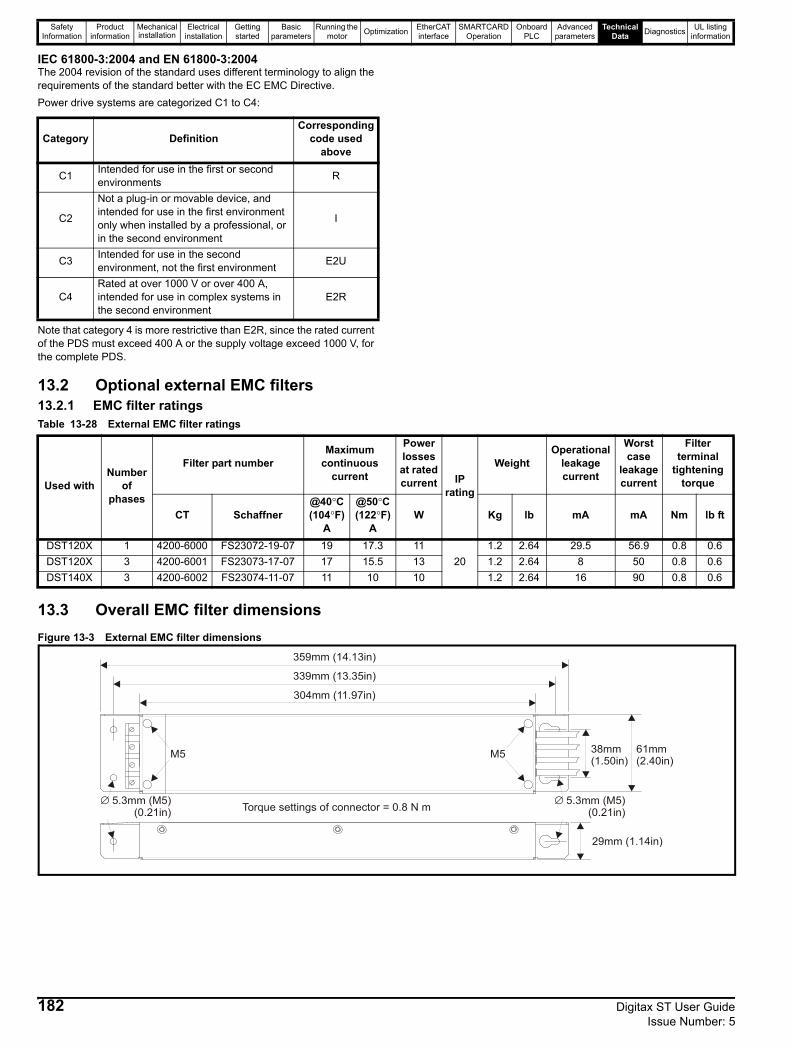
Safety Information
Product information
Mechanical installation
Electrical installation
Getting started
Basic parameters
Running the motor Optimization EtherCAT
interfaceSMARTCARD
OperationOnboard
PLCAdvanced
parametersTechnical
Data Diagnostics UL listing information
IEC 61800-3:2004 and EN 61800-3:2004The 2004 revision of the standard uses different terminology to align the requirements of the standard better with the EC EMC Directive.Power drive systems are categorized C1 to C4:
Note that category 4 is more restrictive than E2R, since the rated current of the PDS must exceed 400 A or the supply voltage exceed 1000 V, for the complete PDS.
13.2 Optional external EMC filters13.2.1 EMC filter ratingsTable 13-28 External EMC filter ratings
13.3 Overall EMC filter dimensionsFigure 13-3 External EMC filter dimensions
Category DefinitionCorresponding
code used above
C1 Intended for use in the first or second environments R
C2
Not a plug-in or movable device, and intended for use in the first environment only when installed by a professional, or in the second environment
I
C3 Intended for use in the second environment, not the first environment E2U
C4Rated at over 1000 V or over 400 A, intended for use in complex systems in the second environment
E2R
Used withNumber
of phases
Filter part numberMaximum
continuous current
Power losses at rated current IP
rating
WeightOperational
leakage current
Worst case
leakage current
Filter terminal
tightening torque
CT Schaffner@40°C(104°F)
A
@50°C(122°F)
AW Kg lb mA mA Nm lb ft
DST120X 1 4200-6000 FS23072-19-07 19 17.3 1120
1.2 2.64 29.5 56.9 0.8 0.6DST120X 3 4200-6001 FS23073-17-07 17 15.5 13 1.2 2.64 8 50 0.8 0.6DST140X 3 4200-6002 FS23074-11-07 11 10 10 1.2 2.64 16 90 0.8 0.6
29mm (1.14in)
359mm (14.13in)
339mm (13.35in)
304mm (11.97in)
38mm(1.50in)
61mm(2.40in)M5 M5
Torque settings of connector = 0.8 N m∅ 5.3mm (M5)(0.21in)
∅ 5.3mm (M5)(0.21in)
182 Digitax ST User Guide Issue Number: 5
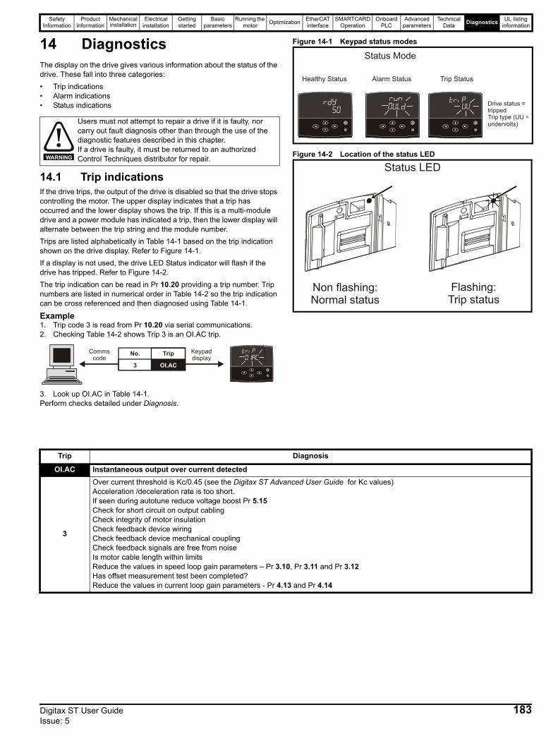
Safety Information
Product information
Mechanical installation
Electrical installation
Getting started
Basic parameters
Running the motor Optimization EtherCAT
interfaceSMARTCARD
OperationOnboard
PLCAdvanced
parametersTechnical
Data Diagnostics UL listing information
14 DiagnosticsThe display on the drive gives various information about the status of the drive. These fall into three categories: • Trip indications • Alarm indications • Status indications
14.1 Trip indicationsIf the drive trips, the output of the drive is disabled so that the drive stops controlling the motor. The upper display indicates that a trip has occurred and the lower display shows the trip. If this is a multi-module drive and a power module has indicated a trip, then the lower display will alternate between the trip string and the module number.Trips are listed alphabetically in Table 14-1 based on the trip indication shown on the drive display. Refer to Figure 14-1.If a display is not used, the drive LED Status indicator will flash if the drive has tripped. Refer to Figure 14-2. The trip indication can be read in Pr 10.20 providing a trip number. Trip numbers are listed in numerical order in Table 14-2 so the trip indication can be cross referenced and then diagnosed using Table 14-1.
Example1. Trip code 3 is read from Pr 10.20 via serial communications.2. Checking Table 14-2 shows Trip 3 is an OI.AC trip.
3. Look up OI.AC in Table 14-1.Perform checks detailed under Diagnosis.
Figure 14-1 Keypad status modes
Figure 14-2 Location of the status LED
Users must not attempt to repair a drive if it is faulty, nor carry out fault diagnosis other than through the use of the diagnostic features described in this chapter.If a drive is faulty, it must be returned to an authorized Control Techniques distributor for repair.WARNING
Keypaddisplay
Commscode
No. Trip
3 OI.AC
Healthy Status Alarm Status Trip Status
Status Mode
Drive status = trippedTrip type (UU =undervolts)
Status LED
Non flashing:Normal status
Flashing:Trip status
Trip Diagnosis
OI.AC Instantaneous output over current detected
3
Over current threshold is Kc/0.45 (see the Digitax ST Advanced User Guide for Kc values)Acceleration /deceleration rate is too short.If seen during autotune reduce voltage boost Pr 5.15 Check for short circuit on output cablingCheck integrity of motor insulationCheck feedback device wiring Check feedback device mechanical coupling Check feedback signals are free from noiseIs motor cable length within limitsReduce the values in speed loop gain parameters – Pr 3.10, Pr 3.11 and Pr 3.12 Has offset measurement test been completed? Reduce the values in current loop gain parameters - Pr 4.13 and Pr 4.14
Digitax ST User Guide 183Issue: 5
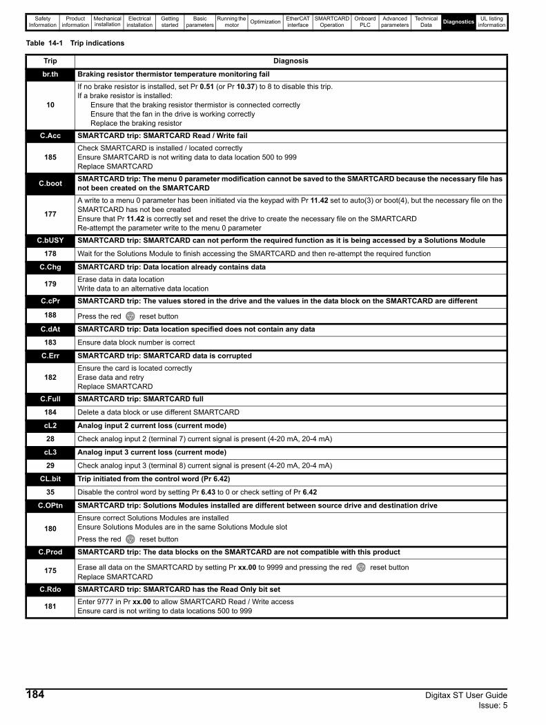
Safety Information
Product information
Mechanical installation
Electrical installation
Getting started
Basic parameters
Running the motor Optimization EtherCAT
interfaceSMARTCARD
OperationOnboard
PLCAdvanced
parametersTechnical
Data Diagnostics UL listing information
Table 14-1 Trip indications
Trip Diagnosis
br.th Braking resistor thermistor temperature monitoring fail
10
If no brake resistor is installed, set Pr 0.51 (or Pr 10.37) to 8 to disable this trip.If a brake resistor is installed:
Ensure that the braking resistor thermistor is connected correctlyEnsure that the fan in the drive is working correctlyReplace the braking resistor
C.Acc SMARTCARD trip: SMARTCARD Read / Write fail
185Check SMARTCARD is installed / located correctlyEnsure SMARTCARD is not writing data to data location 500 to 999Replace SMARTCARD
C.boot SMARTCARD trip: The menu 0 parameter modification cannot be saved to the SMARTCARD because the necessary file has not been created on the SMARTCARD
177
A write to a menu 0 parameter has been initiated via the keypad with Pr 11.42 set to auto(3) or boot(4), but the necessary file on the SMARTCARD has not bee createdEnsure that Pr 11.42 is correctly set and reset the drive to create the necessary file on the SMARTCARDRe-attempt the parameter write to the menu 0 parameter
C.bUSY SMARTCARD trip: SMARTCARD can not perform the required function as it is being accessed by a Solutions Module
178 Wait for the Solutions Module to finish accessing the SMARTCARD and then re-attempt the required function
C.Chg SMARTCARD trip: Data location already contains data
179 Erase data in data locationWrite data to an alternative data location
C.cPr SMARTCARD trip: The values stored in the drive and the values in the data block on the SMARTCARD are different
188 Press the red reset button
C.dAt SMARTCARD trip: Data location specified does not contain any data
183 Ensure data block number is correct
C.Err SMARTCARD trip: SMARTCARD data is corrupted
182Ensure the card is located correctlyErase data and retryReplace SMARTCARD
C.Full SMARTCARD trip: SMARTCARD full
184 Delete a data block or use different SMARTCARD
cL2 Analog input 2 current loss (current mode)
28 Check analog input 2 (terminal 7) current signal is present (4-20 mA, 20-4 mA)
cL3 Analog input 3 current loss (current mode)
29 Check analog input 3 (terminal 8) current signal is present (4-20 mA, 20-4 mA)
CL.bit Trip initiated from the control word (Pr 6.42)
35 Disable the control word by setting Pr 6.43 to 0 or check setting of Pr 6.42
C.OPtn SMARTCARD trip: Solutions Modules installed are different between source drive and destination drive
180Ensure correct Solutions Modules are installed Ensure Solutions Modules are in the same Solutions Module slotPress the red reset button
C.Prod SMARTCARD trip: The data blocks on the SMARTCARD are not compatible with this product
175 Erase all data on the SMARTCARD by setting Pr xx.00 to 9999 and pressing the red reset buttonReplace SMARTCARD
C.Rdo SMARTCARD trip: SMARTCARD has the Read Only bit set
181 Enter 9777 in Pr xx.00 to allow SMARTCARD Read / Write access Ensure card is not writing to data locations 500 to 999
184 Digitax ST User Guide Issue: 5

Safety Information
Product information
Mechanical installation
Electrical installation
Getting started
Basic parameters
Running the motor Optimization EtherCAT
interfaceSMARTCARD
OperationOnboard
PLCAdvanced
parametersTechnical
Data Diagnostics UL listing information
C.rtg SMARTCARD trip: The voltage and/or current rating of the source and destination drives are different
186
Drive rating dependent parameters (parameters with the RA coding) are likely to have different values and ranges with drives of different voltage and current ratings. Parameters with this attribute will not be transferred to the destination drive by SMARTCARDs when the rating of the destination drive is different from the source drive and the file is a parameter file. Drive rating dependent parameters will be transferred if only the current rating is different and the file is a differences from default type file.Press the red reset buttonDrive rating parameters are:
The above parameters will be set to their default values.
C.SLX An error has occurred when attempting to transfer a user program from a Solutions Module to a SMARTCARD and vice versa
172,173,174 See section 10.2.8 SM-Applications Modules And Motion Processors program to/from SMARTCARD transfer system on page 104 for more information.
C.TyP SMARTCARD trip: SMARTCARD parameter set not compatible with drive
187 Press the reset buttonEnsure destination drive type is the same as the source parameter file drive type
dESt Two or more parameters are writing to the same destination parameter
199 Set Pr xx.00 = 12001 check all visible parameters in the menus for duplication
EEF EEPROM data corrupted - Serial comms will timeout with remote keypad on the drive RS485 comms port.
31 This trip can only be cleared by loading default parameters and saving parameters
EnC1 Drive encoder trip: Encoder power supply overload
189 Check encoder power supply wiring and encoder current requirementMaximum current = 200 mA @ 15 V, or 300 mA @ 8 V and 5 V
EnC2 Drive encoder trip: Wire break (Drive encoder terminals 1 & 2, 3 & 4, 5 & 6)
190
Check cable continuityCheck encoder cable is plugged into the encoder input port and not the buffered encoder output port (see Figure 2-3 Features of the drive on page 10).Check wiring of feedback signals is correctCheck encoder power is set correctlyReplace feedback deviceIf wire break detection on the main drive encoder input is not required, set Pr 3.40 = 0 to disable the Enc2 trip
EnC3 Drive encoder trip: Phase offset incorrect While running
191
Check the encoder signal for noiseCheck encoder shieldingCheck the integrity of the encoder mechanical mountingRepeat the offset measurement test
EnC4 Drive encoder trip: Feedback device comms failure
192
Ensure encoder power supply is correctEnsure baud rate is correct Check encoder wiringReplace feedback device
EnC5 Drive encoder trip: Checksum or CRC error
193
Check the encoder signal for noiseCheck the encoder cable shieldingWith EnDat encoders, check the comms resolution and/or carry out the auto-configuration Pr 3.41SSI not ready at start of position transfer (i.e. data input not one)
Trip Diagnosis
Parameter Function2.08 Standard ramp voltage
4.05/6/7, 21.27/8/9 Current limits4.24 User current maximum scaling
5.07, 21.07 Motor rated current5.09, 21.09 Motor rated voltage5.17, 21.12 Stator resistance
5.18 Switching frequency5.23, 21.13 Voltage offset5.24, 21.14 Transient inductance
6.48 Line power supply loss ride through detection level
Digitax ST User Guide 185Issue: 5
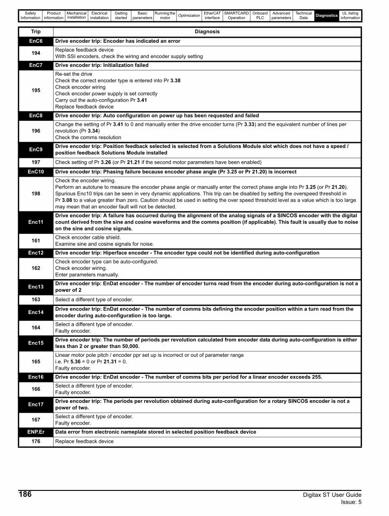
Safety Information
Product information
Mechanical installation
Electrical installation
Getting started
Basic parameters
Running the motor Optimization EtherCAT
interfaceSMARTCARD
OperationOnboard
PLCAdvanced
parametersTechnical
Data Diagnostics UL listing information
EnC6 Drive encoder trip: Encoder has indicated an error
194 Replace feedback deviceWith SSI encoders, check the wiring and encoder supply setting
EnC7 Drive encoder trip: Initialization failed
195
Re-set the driveCheck the correct encoder type is entered into Pr 3.38Check encoder wiringCheck encoder power supply is set correctlyCarry out the auto-configuration Pr 3.41Replace feedback device
EnC8 Drive encoder trip: Auto configuration on power up has been requested and failed
196Change the setting of Pr 3.41 to 0 and manually enter the drive encoder turns (Pr 3.33) and the equivalent number of lines per revolution (Pr 3.34)Check the comms resolution
EnC9 Drive encoder trip: Position feedback selected is selected from a Solutions Module slot which does not have a speed / position feedback Solutions Module installed
197 Check setting of Pr 3.26 (or Pr 21.21 if the second motor parameters have been enabled)
EnC10 Drive encoder trip: Phasing failure because encoder phase angle (Pr 3.25 or Pr 21.20) is incorrect
198
Check the encoder wiring.Perform an autotune to measure the encoder phase angle or manually enter the correct phase angle into Pr 3.25 (or Pr 21.20).Spurious Enc10 trips can be seen in very dynamic applications. This trip can be disabled by setting the overspeed threshold in Pr 3.08 to a value greater than zero. Caution should be used in setting the over speed threshold level as a value which is too large may mean that an encoder fault will not be detected.
Enc11Drive encoder trip: A failure has occurred during the alignment of the analog signals of a SINCOS encoder with the digital count derived from the sine and cosine waveforms and the comms position (if applicable). This fault is usually due to noise on the sine and cosine signals.
161 Check encoder cable shield.Examine sine and cosine signals for noise.
Enc12 Drive encoder trip: Hiperface encoder - The encoder type could not be identified during auto-configuration
162Check encoder type can be auto-configured.Check encoder wiring.Enter parameters manually.
Enc13 Drive encoder trip: EnDat encoder - The number of encoder turns read from the encoder during auto-configuration is not a power of 2
163 Select a different type of encoder.
Enc14 Drive encoder trip: EnDat encoder - The number of comms bits defining the encoder position within a turn read from the encoder during auto-configuration is too large.
164 Select a different type of encoder.Faulty encoder.
Enc15 Drive encoder trip: The number of periods per revolution calculated from encoder data during auto-configuration is either less than 2 or greater than 50,000.
165Linear motor pole pitch / encoder ppr set up is incorrect or out of parameter rangei.e. Pr 5.36 = 0 or Pr 21.31 = 0.Faulty encoder.
Enc16 Drive encoder trip: EnDat encoder - The number of comms bits per period for a linear encoder exceeds 255.
166 Select a different type of encoder.Faulty encoder.
Enc17 Drive encoder trip: The periods per revolution obtained during auto-configuration for a rotary SINCOS encoder is not a power of two.
167 Select a different type of encoder.Faulty encoder.
ENP.Er Data error from electronic nameplate stored in selected position feedback device
176 Replace feedback device
Trip Diagnosis
186 Digitax ST User Guide Issue: 5
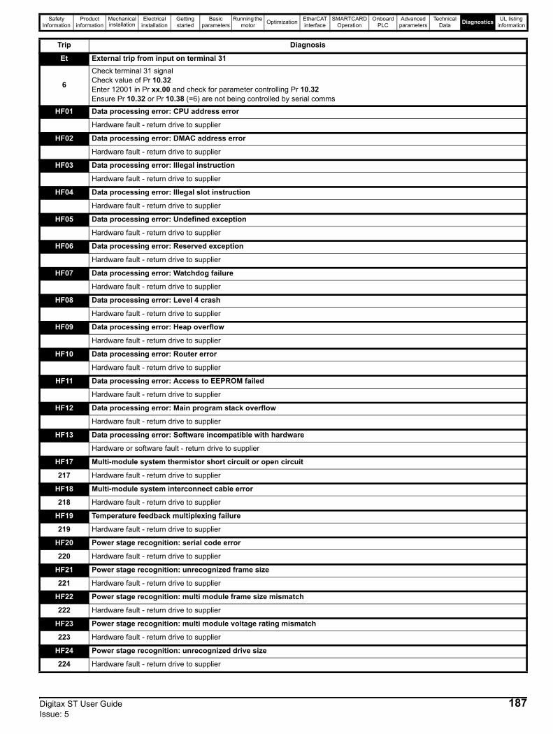
Safety Information
Product information
Mechanical installation
Electrical installation
Getting started
Basic parameters
Running the motor Optimization EtherCAT
interfaceSMARTCARD
OperationOnboard
PLCAdvanced
parametersTechnical
Data Diagnostics UL listing information
Et External trip from input on terminal 31
6
Check terminal 31 signalCheck value of Pr 10.32Enter 12001 in Pr xx.00 and check for parameter controlling Pr 10.32Ensure Pr 10.32 or Pr 10.38 (=6) are not being controlled by serial comms
HF01 Data processing error: CPU address error
Hardware fault - return drive to supplier
HF02 Data processing error: DMAC address error
Hardware fault - return drive to supplier
HF03 Data processing error: Illegal instruction
Hardware fault - return drive to supplier
HF04 Data processing error: Illegal slot instruction
Hardware fault - return drive to supplier
HF05 Data processing error: Undefined exception
Hardware fault - return drive to supplier
HF06 Data processing error: Reserved exception
Hardware fault - return drive to supplier
HF07 Data processing error: Watchdog failure
Hardware fault - return drive to supplier
HF08 Data processing error: Level 4 crash
Hardware fault - return drive to supplier
HF09 Data processing error: Heap overflow
Hardware fault - return drive to supplier
HF10 Data processing error: Router error
Hardware fault - return drive to supplier
HF11 Data processing error: Access to EEPROM failed
Hardware fault - return drive to supplier
HF12 Data processing error: Main program stack overflow
Hardware fault - return drive to supplier
HF13 Data processing error: Software incompatible with hardware
Hardware or software fault - return drive to supplier
HF17 Multi-module system thermistor short circuit or open circuit
217 Hardware fault - return drive to supplier
HF18 Multi-module system interconnect cable error
218 Hardware fault - return drive to supplier
HF19 Temperature feedback multiplexing failure
219 Hardware fault - return drive to supplier
HF20 Power stage recognition: serial code error
220 Hardware fault - return drive to supplier
HF21 Power stage recognition: unrecognized frame size
221 Hardware fault - return drive to supplier
HF22 Power stage recognition: multi module frame size mismatch
222 Hardware fault - return drive to supplier
HF23 Power stage recognition: multi module voltage rating mismatch
223 Hardware fault - return drive to supplier
HF24 Power stage recognition: unrecognized drive size
224 Hardware fault - return drive to supplier
Trip Diagnosis
Digitax ST User Guide 187Issue: 5
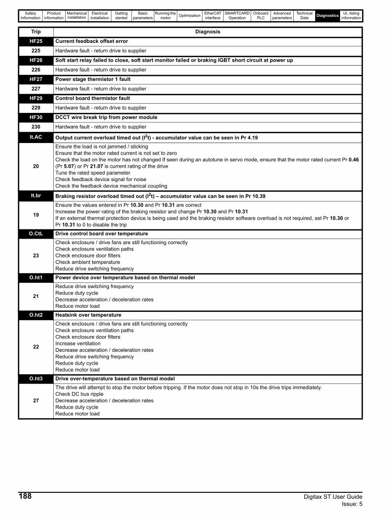
Safety Information
Product information
Mechanical installation
Electrical installation
Getting started
Basic parameters
Running the motor Optimization EtherCAT
interfaceSMARTCARD
OperationOnboard
PLCAdvanced
parametersTechnical
Data Diagnostics UL listing information
HF25 Current feedback offset error
225 Hardware fault - return drive to supplier
HF26 Soft start relay failed to close, soft start monitor failed or braking IGBT short circuit at power up
226 Hardware fault - return drive to supplier
HF27 Power stage thermistor 1 fault
227 Hardware fault - return drive to supplier
HF29 Control board thermistor fault
229 Hardware fault - return drive to supplier
HF30 DCCT wire break trip from power module
230 Hardware fault - return drive to supplier
It.AC Output current overload timed out (I2t) - accumulator value can be seen in Pr 4.19
20
Ensure the load is not jammed / stickingEnsure that the motor rated current is not set to zeroCheck the load on the motor has not changed If seen during an autotune in servo mode, ensure that the motor rated current Pr 0.46 (Pr 5.07) or Pr 21.07 is current rating of the driveTune the rated speed parameter Check feedback device signal for noiseCheck the feedback device mechanical coupling
It.br Braking resistor overload timed out (I2t) – accumulator value can be seen in Pr 10.39
19
Ensure the values entered in Pr 10.30 and Pr 10.31 are correctIncrease the power rating of the braking resistor and change Pr 10.30 and Pr 10.31 If an external thermal protection device is being used and the braking resistor software overload is not required, set Pr 10.30 or Pr 10.31 to 0 to disable the trip
O.CtL Drive control board over temperature
23
Check enclosure / drive fans are still functioning correctlyCheck enclosure ventilation paths Check enclosure door filtersCheck ambient temperatureReduce drive switching frequency
O.ht1 Power device over temperature based on thermal model
21
Reduce drive switching frequencyReduce duty cycleDecrease acceleration / deceleration ratesReduce motor load
O.ht2 Heatsink over temperature
22
Check enclosure / drive fans are still functioning correctlyCheck enclosure ventilation paths Check enclosure door filtersIncrease ventilationDecrease acceleration / deceleration ratesReduce drive switching frequencyReduce duty cycleReduce motor load
O.ht3 Drive over-temperature based on thermal model
27
The drive will attempt to stop the motor before tripping. If the motor does not stop in 10s the drive trips immediately.Check DC bus rippleDecrease acceleration / deceleration ratesReduce duty cycleReduce motor load
Trip Diagnosis
188 Digitax ST User Guide Issue: 5
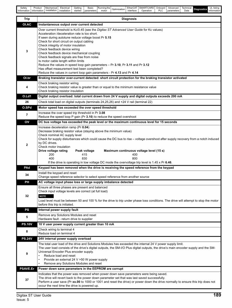
Safety Information
Product information
Mechanical installation
Electrical installation
Getting started
Basic parameters
Running the motor Optimization EtherCAT
interfaceSMARTCARD
OperationOnboard
PLCAdvanced
parametersTechnical
Data Diagnostics UL listing information
OI.AC Instantaneous output over current detected
3
Over current threshold is Kc/0.45 (see the Digitax ST Advanced User Guide for Kc values)Acceleration /deceleration rate is too short.If seen during autotune reduce voltage boost Pr 5.15 Check for short circuit on output cablingCheck integrity of motor insulationCheck feedback device wiring Check feedback device mechanical coupling Check feedback signals are free from noiseIs motor cable length within limitsReduce the values in speed loop gain parameters – Pr 3.10, Pr 3.11 and Pr 3.12 Has offset measurement test been completed? Reduce the values in current loop gain parameters - Pr 4.13 and Pr 4.14
OI.br Braking transistor over-current detected: short circuit protection for the braking transistor activated
4Check braking resistor wiringCheck braking resistor value is greater than or equal to the minimum resistance valueCheck braking resistor insulation
O.Ld1 Digital output overload: total current drawn from 24 V supply and digital outputs exceeds 200 mA
26 Check total load on digital outputs (terminals 24,25,26) and +24 V rail (terminal 22)
O.SPd Motor speed has exceeded the over speed threshold
7 Increase the over speed trip threshold in Pr 3.08 Reduce the speed loop P gain (Pr 3.10) to reduce the speed overshoot
OV DC bus voltage has exceeded the peak level or the maximum continuous level for 15 seconds
2
Increase deceleration ramp (Pr 0.04)Decrease braking resistor value (staying above the minimum value) Check nominal AC supply level Check for supply disturbances which could cause the DC bus to rise – voltage overshoot after supply recovery from a notch induced by DC drives.Check motor insulationDrive voltage rating Peak voltage Maximum continuous voltage level (15 s) 200 415 400 400 830 800 If the drive is operating in low voltage DC mode the overvoltage trip level is 1.45 x Pr 6.46.
PAd Keypad has been removed when the drive is receiving the speed reference from the keypad
34 Install the keypad and resetChange speed reference selector to select speed reference from another source
PH AC voltage input phase loss or large supply imbalance detected
32
Ensure all three phases are present and balancedCheck input voltage levels are correct (at full load)
NLoad level must be between 50 and 100 % for the drive to trip under phase loss conditions. The drive will attempt to stop the motor before this trip is initiated.
PS Internal power supply fault
5 Remove any Solutions Modules and reset Hardware fault - return drive to supplier
PS.10V 10 V user power supply current greater than 10 mA
8 Check wiring to terminal 4Reduce load on terminal 4
PS.24V 24V internal power supply overload
9
The total user load of the drive and Solutions Modules has exceeded the internal 24 V power supply limit.The user load consists of the drive’s digital outputs, the SM-I/O Plus digital outputs, the drive’s main encoder supply and the SM-Universal Encoder Plus encoder supply. • Reduce load and reset• Provide an external 24 V >50 W power supply • Remove any Solutions Modules and reset
PSAVE.Er Power down save parameters in the EEPROM are corrupt
37
Indicates that the power was removed when power down save parameters were being saved.The drive will revert back to the power down parameter set that was last saved successfully.Perform a user save (Pr xx.00 to 1000 or 1001 and reset the drive) or power down the drive normally to ensure this trip does not occur the next time the drive is powered up.
Trip Diagnosis
NOTE
Digitax ST User Guide 189Issue: 5
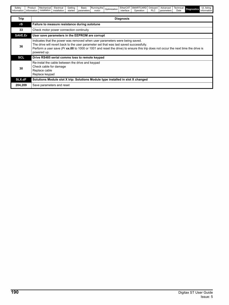
Safety Information
Product information
Mechanical installation
Electrical installation
Getting started
Basic parameters
Running the motor Optimization EtherCAT
interfaceSMARTCARD
OperationOnboard
PLCAdvanced
parametersTechnical
Data Diagnostics UL listing information
rS Failure to measure resistance during autotune
33 Check motor power connection continuity
SAVE.Er User save parameters in the EEPROM are corrupt
36
Indicates that the power was removed when user parameters were being saved.The drive will revert back to the user parameter set that was last saved successfully.Perform a user save (Pr xx.00 to 1000 or 1001 and reset the drive) to ensure this trip does not occur the next time the drive is powered up.
SCL Drive RS485 serial comms loss to remote keypad
30
Re-instal the cable between the drive and keypadCheck cable for damageReplace cableReplace keypad
SLX.dF Solutions Module slot X trip: Solutions Module type installed in slot X changed
204,209 Save parameters and reset
Trip Diagnosis
190 Digitax ST User Guide Issue: 5
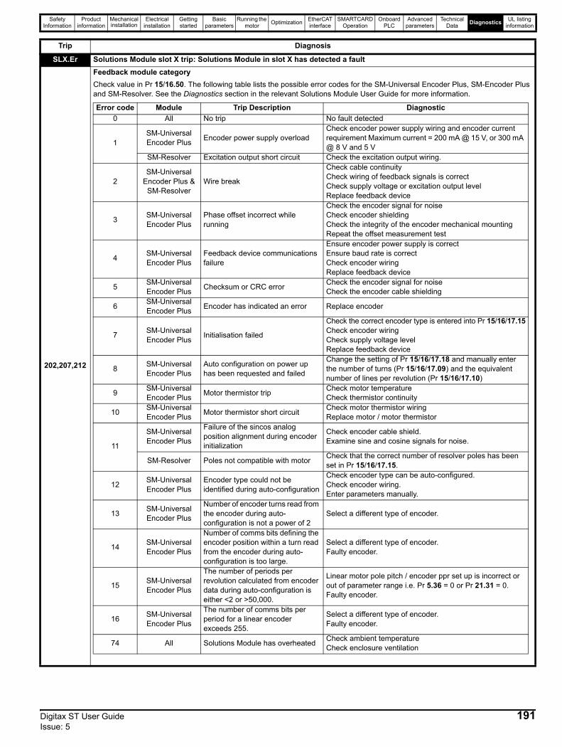
Safety Information
Product information
Mechanical installation
Electrical installation
Getting started
Basic parameters
Running the motor Optimization EtherCAT
interfaceSMARTCARD
OperationOnboard
PLCAdvanced
parametersTechnical
Data Diagnostics UL listing information
SLX.Er Solutions Module slot X trip: Solutions Module in slot X has detected a fault
202,207,212
Feedback module categoryCheck value in Pr 15/16.50. The following table lists the possible error codes for the SM-Universal Encoder Plus, SM-Encoder Plus and SM-Resolver. See the Diagnostics section in the relevant Solutions Module User Guide for more information.
Trip Diagnosis
Error code Module Trip Description Diagnostic0 All No trip No fault detected
1SM-Universal Encoder Plus Encoder power supply overload
Check encoder power supply wiring and encoder current requirement Maximum current = 200 mA @ 15 V, or 300 mA @ 8 V and 5 V
SM-Resolver Excitation output short circuit Check the excitation output wiring.
2SM-Universal
Encoder Plus & SM-Resolver
Wire break
Check cable continuityCheck wiring of feedback signals is correctCheck supply voltage or excitation output levelReplace feedback device
3 SM-Universal Encoder Plus
Phase offset incorrect while running
Check the encoder signal for noiseCheck encoder shieldingCheck the integrity of the encoder mechanical mountingRepeat the offset measurement test
4 SM-Universal Encoder Plus
Feedback device communications failure
Ensure encoder power supply is correctEnsure baud rate is correctCheck encoder wiringReplace feedback device
5 SM-Universal Encoder Plus Checksum or CRC error Check the encoder signal for noise
Check the encoder cable shielding
6 SM-Universal Encoder Plus Encoder has indicated an error Replace encoder
7 SM-Universal Encoder Plus Initialisation failed
Check the correct encoder type is entered into Pr 15/16/17.15Check encoder wiringCheck supply voltage levelReplace feedback device
8 SM-Universal Encoder Plus
Auto configuration on power up has been requested and failed
Change the setting of Pr 15/16/17.18 and manually enter the number of turns (Pr 15/16/17.09) and the equivalent number of lines per revolution (Pr 15/16/17.10)
9 SM-Universal Encoder Plus Motor thermistor trip Check motor temperature
Check thermistor continuity
10 SM-Universal Encoder Plus Motor thermistor short circuit Check motor thermistor wiring
Replace motor / motor thermistor
11
SM-Universal Encoder Plus
Failure of the sincos analog position alignment during encoder initialization
Check encoder cable shield.Examine sine and cosine signals for noise.
SM-Resolver Poles not compatible with motor Check that the correct number of resolver poles has been set in Pr 15/16/17.15.
12 SM-Universal Encoder Plus
Encoder type could not be identified during auto-configuration
Check encoder type can be auto-configured.Check encoder wiring.Enter parameters manually.
13 SM-Universal Encoder Plus
Number of encoder turns read from the encoder during auto-configuration is not a power of 2
Select a different type of encoder.
14 SM-Universal Encoder Plus
Number of comms bits defining the encoder position within a turn read from the encoder during auto-configuration is too large.
Select a different type of encoder.Faulty encoder.
15 SM-Universal Encoder Plus
The number of periods per revolution calculated from encoder data during auto-configuration is either <2 or >50,000.
Linear motor pole pitch / encoder ppr set up is incorrect or out of parameter range i.e. Pr 5.36 = 0 or Pr 21.31 = 0.Faulty encoder.
16 SM-Universal Encoder Plus
The number of comms bits per period for a linear encoder exceeds 255.
Select a different type of encoder.Faulty encoder.
74 All Solutions Module has overheated Check ambient temperatureCheck enclosure ventilation
Digitax ST User Guide 191Issue: 5
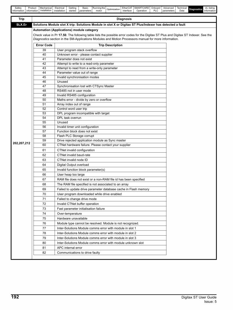
Safety Information
Product information
Mechanical installation
Electrical installation
Getting started
Basic parameters
Running the motor Optimization EtherCAT
interfaceSMARTCARD
OperationOnboard
PLCAdvanced
parametersTechnical
Data Diagnostics UL listing information
SLX.Er Solutions Module slot X trip: Solutions Module in slot X or Digitax ST Plus/Indexer has detected a fault
202,207,212
Automation (Applications) module categoryCheck value in Pr 17.50. The following table lists the possible error codes for the Digitax ST Plus and Digitax ST Indexer. See the Diagnostics section in the SM-Applications Modules and Motion Processors manual for more information.
Trip Diagnosis
Error Code Trip Description39 User program stack overflow40 Unknown error - please contact supplier41 Parameter does not exist42 Attempt to write to a read-only parameter43 Attempt to read from a write-only parameter44 Parameter value out of range45 Invalid synchronisation modes46 Unused47 Synchronisation lost with CTSync Master48 RS485 not in user mode49 Invalid RS485 configuration50 Maths error - divide by zero or overflow51 Array index out of range52 Control word user trip53 DPL program incompatible with target54 DPL task overrun55 Unused56 Invalid timer unit configuration57 Function block does not exist58 Flash PLC Storage corrupt59 Drive rejected application module as Sync master60 CTNet hardware failure. Please contact your supplier
61 CTNet invalid configuration62 CTNet invalid baud-rate63 CTNet invalid node ID64 Digital Output overload65 Invalid function block parameter(s)66 User heap too large67 RAM file does not exist or a non-RAM file id has been specified68 The RAM file specified is not associated to an array69 Failed to update drive parameter database cache in Flash memory70 User program downloaded while drive enabled71 Failed to change drive mode72 Invalid CTNet buffer operation73 Fast parameter initialisation failure74 Over-temperature75 Hardware unavailable76 Module type cannot be resolved. Module is not recognized.77 Inter-Solutions Module comms error with module in slot 178 Inter-Solutions Module comms error with module in slot 279 Inter-Solutions Module comms error with module in slot 380 Inter-Solutions Module comms error with module unknown slot81 APC internal error82 Communications to drive faulty
192 Digitax ST User Guide Issue: 5
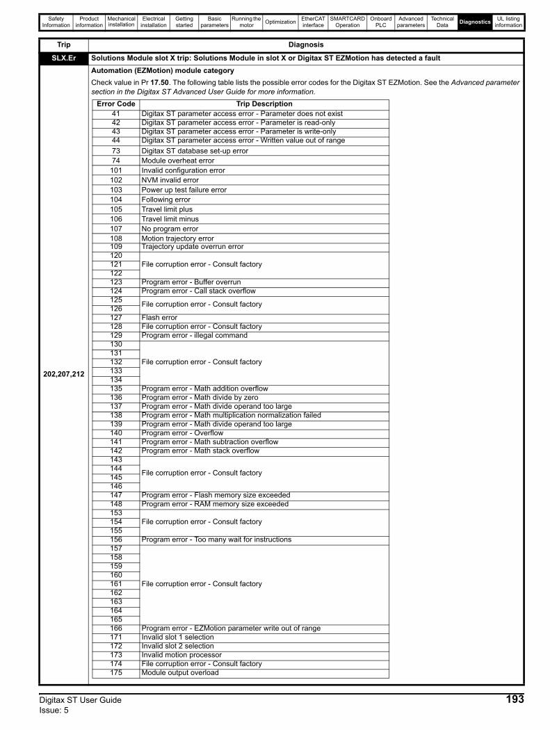
Safety Information
Product information
Mechanical installation
Electrical installation
Getting started
Basic parameters
Running the motor Optimization EtherCAT
interfaceSMARTCARD
OperationOnboard
PLCAdvanced
parametersTechnical
Data Diagnostics UL listing information
SLX.Er Solutions Module slot X trip: Solutions Module in slot X or Digitax ST EZMotion has detected a fault
202,207,212
Automation (EZMotion) module categoryCheck value in Pr 17.50. The following table lists the possible error codes for the Digitax ST EZMotion. See the Advanced parameter section in the Digitax ST Advanced User Guide for more information.
Trip Diagnosis
Error Code Trip Description41 Digitax ST parameter access error - Parameter does not exist42 Digitax ST parameter access error - Parameter is read-only43 Digitax ST parameter access error - Parameter is write-only44 Digitax ST parameter access error - Written value out of range73 Digitax ST database set-up error74 Module overheat error
101 Invalid configuration error102 NVM invalid error103 Power up test failure error104 Following error105 Travel limit plus106 Travel limit minus107 No program error108 Motion trajectory error109 Trajectory update overrun error120
File corruption error - Consult factory121122123 Program error - Buffer overrun124 Program error - Call stack overflow125 File corruption error - Consult factory126127 Flash error128 File corruption error - Consult factory129 Program error - illegal command130
File corruption error - Consult factory131132133134135 Program error - Math addition overflow136 Program error - Math divide by zero 137 Program error - Math divide operand too large138 Program error - Math multiplication normalization failed139 Program error - Math divide operand too large140 Program error - Overflow141 Program error - Math subtraction overflow142 Program error - Math stack overflow143
File corruption error - Consult factory144145146147 Program error - Flash memory size exceeded148 Program error - RAM memory size exceeded153
File corruption error - Consult factory154155156 Program error - Too many wait for instructions157
File corruption error - Consult factory
158159160161162163164165166 Program error - EZMotion parameter write out of range171 Invalid slot 1 selection172 Invalid slot 2 selection173 Invalid motion processor174 File corruption error - Consult factory175 Module output overload
Digitax ST User Guide 193Issue: 5

Safety Information
Product information
Mechanical installation
Electrical installation
Getting started
Basic parameters
Running the motor Optimization EtherCAT
interfaceSMARTCARD
OperationOnboard
PLCAdvanced
parametersTechnical
Data Diagnostics UL listing information
SLX.Er Solutions Module slot X trip: Solutions Module in slot X has detected a fault
202,207,212
Automation (I/O Expansion) module categoryCheck value in Pr 15/16.50. The following table lists the possible error codes for the SM-I/O Plus, SM-I/O Lite, SM-I/O Timer, SM-I/O PELV, SM-I/O 120 V and SM-I/O 24 V Protected. See the Diagnostics section in the relevant Solutions Module User Guide for more information.
SLX.Er Solutions Module slot X trip: Solutions Module in slot X has detected a fault
202,207,212
Fieldbus module categoryCheck value in Pr 15/16.50. The following table lists the possible error codes for the Fieldbus modules. See the Diagnostics section in the relevant Solutions Module User Guide for more information.
Trip Diagnosis
Error code Module Reason for fault0 All No errors1 All Digital output overload
2SM-I/O Lite, SM-I/O Timer Analog input 1 current input too high (>22 mA) or too low (<3 mA)
SM-I/O PELV, SM-I/O 24V Protected Digital input overload
3SM-I/O PELV, SM-I/O 24V Protected Analog input 1 current input too low (<3 mA)
SM-I/O 24V Protected Communications error4 SM-I/O PELV User power supply absent5 SM-I/O Timer Real time clock communication error
74 All Module over temperature
Error code Module Trip Description0 All No trip
52 SM-PROFIBUS-DP-V1, SM-Interbus, SM-DeviceNet, SM-CANOpen User control word trip
61 SM-PROFIBUS-DP-V1, SM-Interbus, SM-DeviceNet, SM-CANOpen, SM-SERCOS Configuration error
64 SM-DeviceNet Expected packet rate timeout
65 SM-PROFIBUS-DP-V1, SM-Interbus, SM-DeviceNet, SM-CANOpen, SM-SERCOS Network loss
66SM-PROFIBUS-DP-V1 Critical link failure
SM-CAN, SM-DeviceNet, SM-CANOpen Bus off error69 SM-CAN No acknowledgement
70All (except SM-Ethernet) Flash transfer error
SM-Ethernet No valid menu data available for the module from the drive74 All Solutions module over temperature75 SM-Ethernet The drive is not responding76 SM-Ethernet The Modbus connection has timed out80 All (except SM-SERCOS) Inter-option communications error81 All (except SM-SERCOS) Communications error to slot 182 All (except SM-SERCOS) Communications error to slot 283 All (except SM-SERCOS) Communications error to slot 3
84 SM-Ethernet Memory allocation error
85 SM-Ethernet File system error
86 SM-Ethernet Configuration file error
87 SM-Ethernet Language file error
98 All Internal watchdog error
99 All Internal software error
194 Digitax ST User Guide Issue: 5
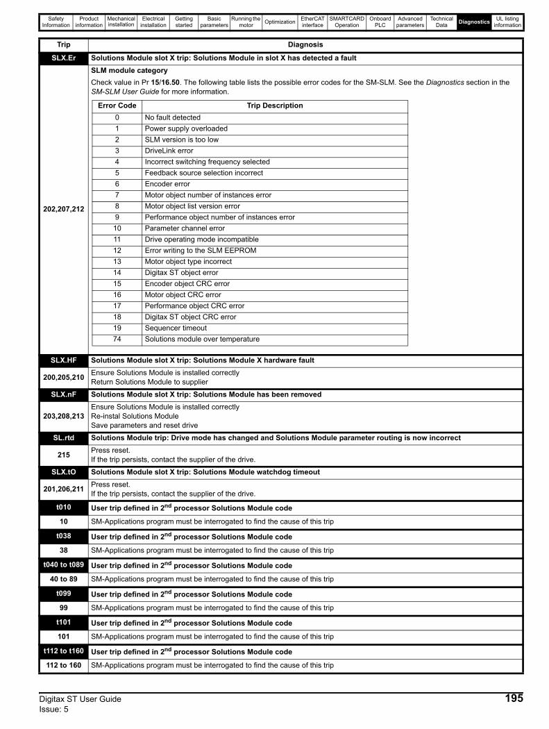
Safety Information
Product information
Mechanical installation
Electrical installation
Getting started
Basic parameters
Running the motor Optimization EtherCAT
interfaceSMARTCARD
OperationOnboard
PLCAdvanced
parametersTechnical
Data Diagnostics UL listing information
SLX.Er Solutions Module slot X trip: Solutions Module in slot X has detected a fault
202,207,212
SLM module categoryCheck value in Pr 15/16.50. The following table lists the possible error codes for the SM-SLM. See the Diagnostics section in the SM-SLM User Guide for more information.
SLX.HF Solutions Module slot X trip: Solutions Module X hardware fault
200,205,210 Ensure Solutions Module is installed correctlyReturn Solutions Module to supplier
SLX.nF Solutions Module slot X trip: Solutions Module has been removed
203,208,213Ensure Solutions Module is installed correctlyRe-instal Solutions ModuleSave parameters and reset drive
SL.rtd Solutions Module trip: Drive mode has changed and Solutions Module parameter routing is now incorrect
215 Press reset.If the trip persists, contact the supplier of the drive.
SLX.tO Solutions Module slot X trip: Solutions Module watchdog timeout
201,206,211 Press reset.If the trip persists, contact the supplier of the drive.
t010 User trip defined in 2nd processor Solutions Module code
10 SM-Applications program must be interrogated to find the cause of this trip
t038 User trip defined in 2nd processor Solutions Module code
38 SM-Applications program must be interrogated to find the cause of this trip
t040 to t089 User trip defined in 2nd processor Solutions Module code
40 to 89 SM-Applications program must be interrogated to find the cause of this trip
t099 User trip defined in 2nd processor Solutions Module code
99 SM-Applications program must be interrogated to find the cause of this trip
t101 User trip defined in 2nd processor Solutions Module code
101 SM-Applications program must be interrogated to find the cause of this trip
t112 to t160 User trip defined in 2nd processor Solutions Module code
112 to 160 SM-Applications program must be interrogated to find the cause of this trip
Trip Diagnosis
Error Code Trip Description0 No fault detected1 Power supply overloaded2 SLM version is too low3 DriveLink error4 Incorrect switching frequency selected5 Feedback source selection incorrect6 Encoder error7 Motor object number of instances error8 Motor object list version error9 Performance object number of instances error
10 Parameter channel error11 Drive operating mode incompatible12 Error writing to the SLM EEPROM13 Motor object type incorrect14 Digitax ST object error15 Encoder object CRC error16 Motor object CRC error17 Performance object CRC error18 Digitax ST object CRC error19 Sequencer timeout74 Solutions module over temperature
Digitax ST User Guide 195Issue: 5
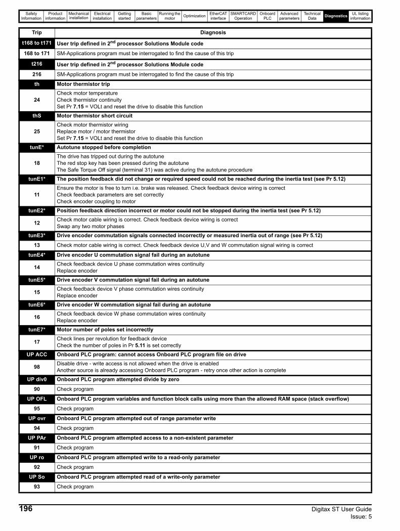
Safety Information
Product information
Mechanical installation
Electrical installation
Getting started
Basic parameters
Running the motor Optimization EtherCAT
interfaceSMARTCARD
OperationOnboard
PLCAdvanced
parametersTechnical
Data Diagnostics UL listing information
t168 to t171 User trip defined in 2nd processor Solutions Module code
168 to 171 SM-Applications program must be interrogated to find the cause of this trip
t216 User trip defined in 2nd processor Solutions Module code
216 SM-Applications program must be interrogated to find the cause of this trip
th Motor thermistor trip
24Check motor temperatureCheck thermistor continuitySet Pr 7.15 = VOLt and reset the drive to disable this function
thS Motor thermistor short circuit
25Check motor thermistor wiringReplace motor / motor thermistorSet Pr 7.15 = VOLt and reset the drive to disable this function
tunE* Autotune stopped before completion
18The drive has tripped out during the autotuneThe red stop key has been pressed during the autotuneThe Safe Torque Off signal (terminal 31) was active during the autotune procedure
tunE1* The position feedback did not change or required speed could not be reached during the inertia test (see Pr 5.12)
11Ensure the motor is free to turn i.e. brake was released. Check feedback device wiring is correctCheck feedback parameters are set correctlyCheck encoder coupling to motor
tunE2* Position feedback direction incorrect or motor could not be stopped during the inertia test (see Pr 5.12)
12 Check motor cable wiring is correct. Check feedback device wiring is correctSwap any two motor phases
tunE3* Drive encoder commutation signals connected incorrectly or measured inertia out of range (see Pr 5.12)
13 Check motor cable wiring is correct. Check feedback device U,V and W commutation signal wiring is correct
tunE4* Drive encoder U commutation signal fail during an autotune
14 Check feedback device U phase commutation wires continuityReplace encoder
tunE5* Drive encoder V commutation signal fail during an autotune
15 Check feedback device V phase commutation wires continuityReplace encoder
tunE6* Drive encoder W commutation signal fail during an autotune
16 Check feedback device W phase commutation wires continuity Replace encoder
tunE7* Motor number of poles set incorrectly
17 Check lines per revolution for feedback deviceCheck the number of poles in Pr 5.11 is set correctly
UP ACC Onboard PLC program: cannot access Onboard PLC program file on drive
98 Disable drive - write access is not allowed when the drive is enabledAnother source is already accessing Onboard PLC program - retry once other action is complete
UP div0 Onboard PLC program attempted divide by zero
90 Check program
UP OFL Onboard PLC program variables and function block calls using more than the allowed RAM space (stack overflow)
95 Check program
UP ovr Onboard PLC program attempted out of range parameter write
94 Check program
UP PAr Onboard PLC program attempted access to a non-existent parameter
91 Check program
UP ro Onboard PLC program attempted write to a read-only parameter
92 Check program
UP So Onboard PLC program attempted read of a write-only parameter
93 Check program
Trip Diagnosis
196 Digitax ST User Guide Issue: 5
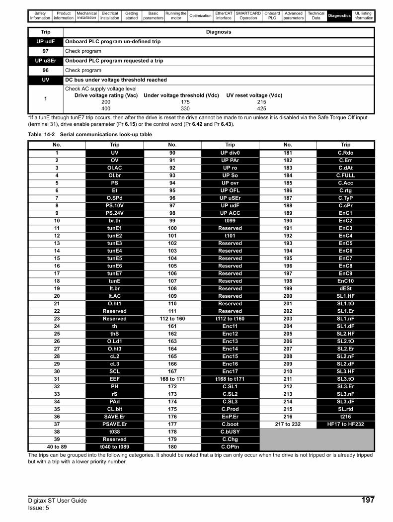
Safety Information
Product information
Mechanical installation
Electrical installation
Getting started
Basic parameters
Running the motor Optimization EtherCAT
interfaceSMARTCARD
OperationOnboard
PLCAdvanced
parametersTechnical
Data Diagnostics UL listing information
*If a tunE through tunE7 trip occurs, then after the drive is reset the drive cannot be made to run unless it is disabled via the Safe Torque Off input (terminal 31), drive enable parameter (Pr 6.15) or the control word (Pr 6.42 and Pr 6.43).
Table 14-2 Serial communications look-up table
The trips can be grouped into the following categories. It should be noted that a trip can only occur when the drive is not tripped or is already tripped but with a trip with a lower priority number.
UP udF Onboard PLC program un-defined trip
97 Check program
UP uSEr Onboard PLC program requested a trip
96 Check program
UV DC bus under voltage threshold reached
1
Check AC supply voltage levelDrive voltage rating (Vac) Under voltage threshold (Vdc) UV reset voltage (Vdc)
200 175 215 400 330 425
Trip Diagnosis
No. Trip No. Trip No. Trip1 UV 90 UP div0 181 C.Rdo2 OV 91 UP PAr 182 C.Err3 OI.AC 92 UP ro 183 C.dAt4 OI.br 93 UP So 184 C.FULL5 PS 94 UP ovr 185 C.Acc6 Et 95 UP OFL 186 C.rtg7 O.SPd 96 UP uSEr 187 C.TyP8 PS.10V 97 UP udF 188 C.cPr9 PS.24V 98 UP ACC 189 EnC1
10 br.th 99 t099 190 EnC211 tunE1 100 Reserved 191 EnC312 tunE2 101 t101 192 EnC413 tunE3 102 Reserved 193 EnC514 tunE4 103 Reserved 194 EnC615 tunE5 104 Reserved 195 EnC716 tunE6 105 Reserved 196 EnC817 tunE7 106 Reserved 197 EnC918 tunE 107 Reserved 198 EnC1019 It.br 108 Reserved 199 dESt20 It.AC 109 Reserved 200 SL1.HF21 O.ht1 110 Reserved 201 SL1.tO22 Reserved 111 Reserved 202 SL1.Er23 Reserved 112 to 160 t112 to t160 203 SL1.nF24 th 161 Enc11 204 SL1.dF25 thS 162 Enc12 205 SL2.HF26 O.Ld1 163 Enc13 206 SL2.tO27 O.ht3 164 Enc14 207 SL2.Er28 cL2 165 Enc15 208 SL2.nF29 cL3 166 Enc16 209 SL2.dF30 SCL 167 Enc17 210 SL3.HF31 EEF 168 to 171 t168 to t171 211 SL3.tO32 PH 172 C.SL1 212 SL3.Er33 rS 173 C.SL2 213 SL3.nF34 PAd 174 C.SL3 214 SL3.dF35 CL.bit 175 C.Prod 215 SL.rtd36 SAVE.Er 176 EnP.Er 216 t21637 PSAVE.Er 177 C.boot 217 to 232 HF17 to HF23238 t038 178 C.bUSY39 Reserved 179 C.Chg
40 to 89 t040 to t089 180 C.OPtn
Digitax ST User Guide 197Issue: 5
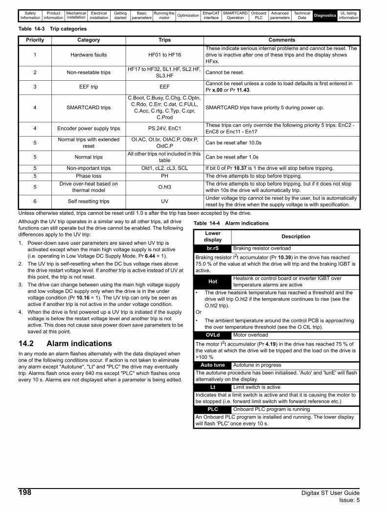
Safety Information
Product information
Mechanical installation
Electrical installation
Getting started
Basic parameters
Running the motor Optimization EtherCAT
interfaceSMARTCARD
OperationOnboard
PLCAdvanced
parametersTechnical
Data Diagnostics UL listing information
Table 14-3 Trip categories
Unless otherwise stated, trips cannot be reset until 1.0 s after the trip has been accepted by the drive.Although the UV trip operates in a similar way to all other trips, all drive functions can still operate but the drive cannot be enabled. The following differences apply to the UV trip:1. Power-down save user parameters are saved when UV trip is
activated except when the main high voltage supply is not active (i.e. operating in Low Voltage DC Supply Mode, Pr 6.44 = 1).
2. The UV trip is self-resetting when the DC bus voltage rises above the drive restart voltage level. If another trip is active instead of UV at this point, the trip is not reset.
3. The drive can change between using the main high voltage supply and low voltage DC supply only when the drive is in the under voltage condition (Pr 10.16 = 1). The UV trip can only be seen as active if another trip is not active in the under voltage condition.
4. When the drive is first powered up a UV trip is initiated if the supply voltage is below the restart voltage level and another trip is not active. This does not cause save power down save parameters to be saved at this point.
14.2 Alarm indicationsIn any mode an alarm flashes alternately with the data displayed when one of the following conditions occur. If action is not taken to eliminate any alarm except "Autotune", "Lt" and "PLC" the drive may eventually trip. Alarms flash once every 640 ms except "PLC" which flashes once every 10 s. Alarms are not displayed when a parameter is being edited.
Table 14-4 Alarm indications
Priority Category Trips Comments
1 Hardware faults HF01 to HF16These indicate serious internal problems and cannot be reset. The drive is inactive after one of these trips and the display shows HFxx.
2 Non-resetable trips HF17 to HF32, SL1.HF, SL2.HF, SL3.HF Cannot be reset.
3 EEF trip EEF Cannot be reset unless a code to load defaults is first entered in Pr x.00 or Pr 11.43.
4 SMARTCARD trips
C.Boot, C.Busy, C.Chg, C.Optn, C.Rdo, C.Err, C.dat, C.FULL,
C.Acc, C.rtg, C.Typ, C.cpr, C.Prod
SMARTCARD trips have priority 5 during power up.
4 Encoder power supply trips PS.24V, EnC1 These trips can only override the following priority 5 trips: EnC2 - EnC8 or Enc11 - En17
5 Normal trips with extended reset
OI.AC, OI.br, OIAC.P, OIbr.P, OidC.P Can be reset after 10.0s
5 Normal trips All other trips not included in this table Can be reset after 1.0s
5 Non-important trips Old1, cL2, cL3, SCL If bit 0 of Pr 10.37 is 1 the drive will stop before tripping.5 Phase loss PH The drive attempts to stop before tripping.
5 Drive over-heat based on thermal model O.ht3 The drive attempts to stop before tripping, but if it does not stop
within 10s the drive will automatically trip.
6 Self resetting trips UV Under voltage trip cannot be reset by the user, but is automatically reset by the drive when the supply voltage is with specification.
Lower display Description
br.rS Braking resistor overload
Braking resistor I2t accumulator (Pr 10.39) in the drive has reached 75.0 % of the value at which the drive will trip and the braking IGBT is active.
Hot Heatsink or control board or inverter IGBT over temperature alarms are active
• The drive heatsink temperature has reached a threshold and the drive will trip O.ht2 if the temperature continues to rise (see the O.ht2 trip).
Or• The ambient temperature around the control PCB is approaching
the over temperature threshold (see the O.CtL trip).OVLd Motor overload
The motor I2t accumulator (Pr 4.19) in the drive has reached 75 % of the value at which the drive will be tripped and the load on the drive is >100 %
Auto tune Autotune in progressThe autotune procedure has been initialised. 'Auto' and 'tunE' will flash alternatively on the display.
Lt Limit switch is activeIndicates that a limit switch is active and that it is causing the motor to be stopped (i.e. forward limit switch with forward reference etc.)
PLC Onboard PLC program is runningAn Onboard PLC program is installed and running. The lower display will flash 'PLC' once every 10 s.
198 Digitax ST User Guide Issue: 5
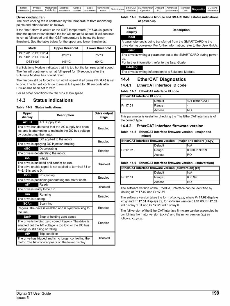
Safety Information
Product information
Mechanical installation
Electrical installation
Getting started
Basic parameters
Running the motor Optimization EtherCAT
interfaceSMARTCARD
OperationOnboard
PLCAdvanced
parametersTechnical
Data Diagnostics UL listing information
Drive cooling fanThe drive cooling fan is controlled by the temperature from monitoring points and other actions as follows:If the "hot" alarm is active or the IGBT temperature (Pr 7.34) is greater than the upper threshold then the fan will run at full speed. It will continue to run at full speed until the IGBT temperature is below the lower threshold. See the table below for the upper and lower thresholds.
If a Solutions Module indicates that it is too hot the fan runs at full speed. The fan will continue to run at full speed for 10 seconds after the Solutions Module has cooled down.The fan can still be forced to run at full speed at all times if Pr 6.45 is set to one. The fan will continue to run at full speed for 10 seconds after Pr 6.45 has been set to zero.For all other conditions the fan runs at low speed.
14.3 Status indicationsTable 14-5 Status indications
Table 14-6 Solutions Module and SMARTCARD status indications at power-up
14.4 EtherCAT Diagnostics14.4.1 EtherCAT interface ID codeTable 14-7 EtherCAT interface ID code
This parameter is useful for checking the The EtherCAT interface is of the correct type.
14.4.2 EtherCAT interface firmware versionTable 14-8 EtherCAT interface firmware version - (major and
minor)
Table 14-9 EtherCAT interface firmware version - (subversion)
The software version of the EtherCAT interface can be identified by looking at Pr 17.02 and Pr 17.51.
The software version takes the form of xx.yy.zz, where Pr 17.02 displays xx.yy and Pr 17.51 displays zz, for software version 01.01.00, Pr 17.02 will display 1.01 and Pr 17.51 will display 0.
The full version of the EtherCAT interface firmware can be assembled by combining the major version (xx.yy) and the minor version (zz) as follows: xx.yy.zz.
Model Upper threshold Lower thresholdDST1201 to DST1204DST1401 to DST1404 120 ºC 75 ºC
DST1405 145 ºC 90 ºC
Upper display Description Drive output
stageACUU AC Supply loss
EnabledThe drive has detected that the AC supply has been lost and is attempting to maintain the DC bus voltage by decelerating the motor.
dc DC applied to the motorEnabled
The drive is applying DC injection braking.dEC Decelerating
EnabledThe drive is decelerating the motor.
inh Inhibit
DisabledThe drive is inhibited and cannot be run.The drive enable signal is not applied to terminal 31 or Pr 6.15 is set to 0.
POS PositioningEnabled
The drive is positioning/orientating the motor shaft.rdY Ready
DisabledThe drive is ready to be run.
run Running EnabledThe drive is running.
SCAn ScanningEnabledRegen> The drive is enabled and is synchronising to
the line.StoP Stop or holding zero speed
EnabledThe drive is holding zero speed.Regen> The drive is enabled but the AC voltage is too low, or the DC bus voltage is still rising or falling.
triP Trip conditionDisabledThe drive has tripped and is no longer controlling the
motor. The trip code appears on the lower display.
Lower display Description
bootA parameter set is being transferred from the SMARTCARD to the drive during power-up. For further information, refer to the User Guide.
cArdThe drive is writing a parameter set to the SMARTCARD during power-up.For further information, refer to the User Guide.
loAdingThe drive is writing information to a Solutions Module.
EtherCAT interface ID code
Pr 17.01Default 421 (EtherCAT)Range -Access RO
EtherCAT interface firmware version - (major and minor) (xx.yy)
Pr 17.02Default N/ARange 00.00 to 99.99Access RO
EtherCAT interface firmware version (subversion) (zz)
Pr 17.51Default N/ARange 0 to 99Access RO
Digitax ST User Guide 199Issue: 5
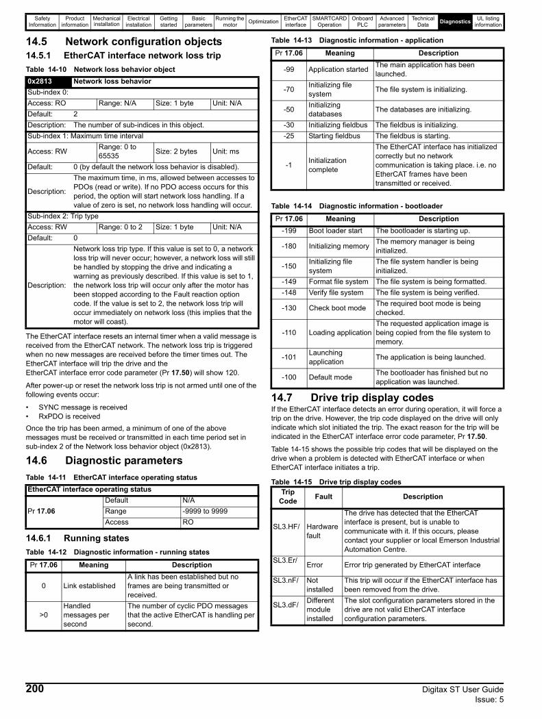
Safety Information
Product information
Mechanical installation
Electrical installation
Getting started
Basic parameters
Running the motor Optimization EtherCAT
interfaceSMARTCARD
OperationOnboard
PLCAdvanced
parametersTechnical
Data Diagnostics UL listing information
14.5 Network configuration objects14.5.1 EtherCAT interface network loss tripTable 14-10 Network loss behavior object
The EtherCAT interface resets an internal timer when a valid message is received from the EtherCAT network. The network loss trip is triggered when no new messages are received before the timer times out. The EtherCAT interface will trip the drive and the EtherCAT interface error code parameter (Pr 17.50) will show 120.
After power-up or reset the network loss trip is not armed until one of the following events occur:
• SYNC message is received• RxPDO is receivedOnce the trip has been armed, a minimum of one of the above messages must be received or transmitted in each time period set in sub-index 2 of the Network loss behavior object (0x2813).
14.6 Diagnostic parametersTable 14-11 EtherCAT interface operating status
14.6.1 Running statesTable 14-12 Diagnostic information - running states
Table 14-13 Diagnostic information - application
Table 14-14 Diagnostic information - bootloader
14.7 Drive trip display codesIf the EtherCAT interface detects an error during operation, it will force a trip on the drive. However, the trip code displayed on the drive will only indicate which slot initiated the trip. The exact reason for the trip will be indicated in the EtherCAT interface error code parameter, Pr 17.50.
Table 14-15 shows the possible trip codes that will be displayed on the drive when a problem is detected with EtherCAT interface or when EtherCAT interface initiates a trip.
Table 14-15 Drive trip display codes
0x2813 Network loss behaviorSub-index 0:Access: RO Range: N/A Size: 1 byte Unit: N/ADefault: 2Description: The number of sub-indices in this object.Sub-index 1: Maximum time interval
Access: RW Range: 0 to 65535 Size: 2 bytes Unit: ms
Default: 0 (by default the network loss behavior is disabled).
Description:
The maximum time, in ms, allowed between accesses to PDOs (read or write). If no PDO access occurs for this period, the option will start network loss handling. If a value of zero is set, no network loss handling will occur.
Sub-index 2: Trip typeAccess: RW Range: 0 to 2 Size: 1 byte Unit: N/ADefault: 0
Description:
Network loss trip type. If this value is set to 0, a network loss trip will never occur; however, a network loss will still be handled by stopping the drive and indicating a warning as previously described. If this value is set to 1, the network loss trip will occur only after the motor has been stopped according to the Fault reaction option code. If the value is set to 2, the network loss trip will occur immediately on network loss (this implies that the motor will coast).
EtherCAT interface operating status
Pr 17.06Default N/ARange -9999 to 9999Access RO
Pr 17.06 Meaning Description
0 Link establishedA link has been established but no frames are being transmitted or received.
>0Handled messages per second
The number of cyclic PDO messages that the active EtherCAT is handling per second.
Pr 17.06 Meaning Description
-99 Application started The main application has been launched.
-70 Initializing file system The file system is initializing.
-50 Initializing databases The databases are initializing.
-30 Initializing fieldbus The fieldbus is initializing.-25 Starting fieldbus The fieldbus is starting.
-1 Initialization complete
The EtherCAT interface has initialized correctly but no network communication is taking place. i.e. no EtherCAT frames have been transmitted or received.
Pr 17.06 Meaning Description-199 Boot loader start The bootloader is starting up.
-180 Initializing memory The memory manager is being initialized.
-150 Initializing file system
The file system handler is being initialized.
-149 Format file system The file system is being formatted.-148 Verify file system The file system is being verified.
-130 Check boot mode The required boot mode is being checked.
-110 Loading applicationThe requested application image is being copied from the file system to memory.
-101 Launching application The application is being launched.
-100 Default mode The bootloader has finished but no application was launched.
Trip Code Fault Description
SL3.HF/ Hardware fault
The drive has detected that the EtherCAT interface is present, but is unable to communicate with it. If this occurs, please contact your supplier or local Emerson Industrial Automation Centre.
SL3.Er/ Error Error trip generated by EtherCAT interface
SL3.nF/ Not installed
This trip will occur if the EtherCAT interface has been removed from the drive.
SL3.dF/ Different module installed
The slot configuration parameters stored in the drive are not valid EtherCAT interface configuration parameters.
200 Digitax ST User Guide Issue: 5
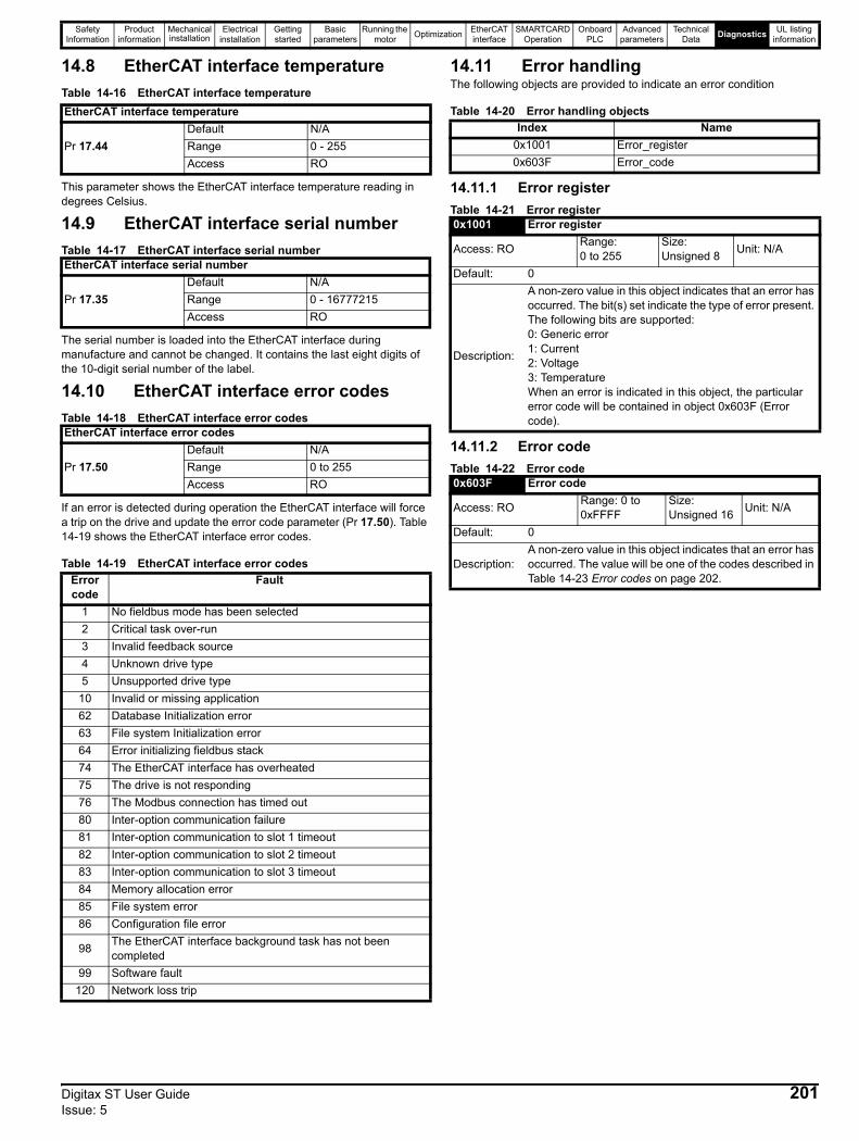
Safety Information
Product information
Mechanical installation
Electrical installation
Getting started
Basic parameters
Running the motor Optimization EtherCAT
interfaceSMARTCARD
OperationOnboard
PLCAdvanced
parametersTechnical
Data Diagnostics UL listing information
14.8 EtherCAT interface temperatureTable 14-16 EtherCAT interface temperature
This parameter shows the EtherCAT interface temperature reading in degrees Celsius.
14.9 EtherCAT interface serial numberTable 14-17 EtherCAT interface serial number
The serial number is loaded into the EtherCAT interface during manufacture and cannot be changed. It contains the last eight digits of the 10-digit serial number of the label.
14.10 EtherCAT interface error codesTable 14-18 EtherCAT interface error codes
If an error is detected during operation the EtherCAT interface will force a trip on the drive and update the error code parameter (Pr 17.50). Table 14-19 shows the EtherCAT interface error codes.
Table 14-19 EtherCAT interface error codes
14.11 Error handlingThe following objects are provided to indicate an error condition
Table 14-20 Error handling objects
14.11.1 Error registerTable 14-21 Error register
14.11.2 Error codeTable 14-22 Error code
EtherCAT interface temperature
Pr 17.44Default N/ARange 0 - 255Access RO
EtherCAT interface serial number
Pr 17.35Default N/ARange 0 - 16777215Access RO
EtherCAT interface error codes
Pr 17.50Default N/ARange 0 to 255Access RO
Error code
Fault
1 No fieldbus mode has been selected2 Critical task over-run3 Invalid feedback source4 Unknown drive type5 Unsupported drive type
10 Invalid or missing application62 Database Initialization error63 File system Initialization error64 Error initializing fieldbus stack74 The EtherCAT interface has overheated75 The drive is not responding76 The Modbus connection has timed out80 Inter-option communication failure81 Inter-option communication to slot 1 timeout82 Inter-option communication to slot 2 timeout83 Inter-option communication to slot 3 timeout84 Memory allocation error85 File system error86 Configuration file error
98 The EtherCAT interface background task has not been completed
99 Software fault120 Network loss trip
Index Name0x1001 Error_register0x603F Error_code
0x1001 Error register
Access: RO Range: 0 to 255
Size: Unsigned 8 Unit: N/A
Default: 0
Description:
A non-zero value in this object indicates that an error has occurred. The bit(s) set indicate the type of error present. The following bits are supported:0: Generic error1: Current2: Voltage3: TemperatureWhen an error is indicated in this object, the particular error code will be contained in object 0x603F (Error code).
0x603F Error code
Access: RO Range: 0 to 0xFFFF
Size: Unsigned 16 Unit: N/A
Default: 0
Description:A non-zero value in this object indicates that an error has occurred. The value will be one of the codes described in Table 14-23 Error codes on page 202.
Digitax ST User Guide 201Issue: 5
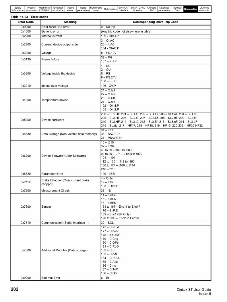
Safety Information
Product information
Mechanical installation
Electrical installation
Getting started
Basic parameters
Running the motor Optimization EtherCAT
interfaceSMARTCARD
OperationOnboard
PLCAdvanced
parametersTechnical
Data Diagnostics UL listing information
Table 14-23 Error codesError Code Meaning Corresponding Drive Trip Code
0x0000 Error reset / No error 0 – No trip0x1000 Generic error (Any trip code not elsewhere in table)0x2200 Internal current 109 - OIdC.P
0x2300 Current, device output side3 – OI.AC20 – It.AC104 - OIAC.P
0x3000 Voltage 8 – PS.10V
0x3130 Phase failure 32 – PH107 – PH.P
0x3200 Voltage inside the device
1 – UU2 – OU5 – PS9 – PS.24V108 – PS.P
0x3210 dc bus over-voltage 106 - OV.P
0x4200 Temperature device
21 – O.ht122 – O.ht223 – O.CtL27 – O.ht3102 – Oht4.P105 – Oht2.P
0x5000 Device hardware
200 – SL1.HF, 201 – SL1.t0, 202 – SL1.Er, 203 – SL1.nF, 204 – SL1.dF205 – SL2.HF, 206 – SL2.t0, 207 – SL2.Er, 208 – SL2.nF, 209 – SL2.dF210 – SL3.HF, 211 – SL3.t0, 212 – SL3.Er, 213 – SL3.nF, 214 – SL3.dF215 – SL.rtd, 217 – HF17, 218 – HF18, 219 – HF19, 220-232 – HF20-HF32
0x5530 Data Storage (Non-volatile data memory)31 – EEF36 – SAVE.Er37 – PSAVE.Er
0x6200 Device Software (User Software)
10 – t01032 – t03840 to 89 – t040 to t08990 to 99 – UP --- / t090 to t099101 – t101112 to 160 – t112 to t160168 to 174 – t168 to t174216 – t216
0x6320 Parameter Error 199 - dESt
0x7112 Brake Chopper (Over current brake chopper)
4 – OI.br19 – It.br103 – OIbr.P
0x7200 Measurement Circuit 33 – rS
0x7300 Sensor
14 – tunE415 – tunE516 – tunE6161 to 167 – Enc11 to Enc17176 – EnP.Er189 – Enc1 (SP Only)190 to 198 – Enc2 to Enc10
0x7510 Communication (Serial Interface 1) 30 – SCL
0x7600 Additional Modules (Data storage)
175 – C.Prod177 – C.boot178 – c.bUSY179 – C.Chg180 – C.OPtn181 – C.RdO182 – C.Err183 – C.dAt184 – C.FULL185 – C.Acc186 – C.rtg187 – C.TyP188 – C.cPr
0x9000 External Error 6 – Et
202 Digitax ST User Guide Issue: 5
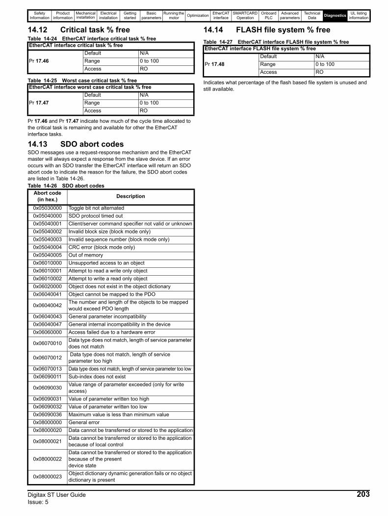
Safety Information
Product information
Mechanical installation
Electrical installation
Getting started
Basic parameters
Running the motor Optimization EtherCAT
interfaceSMARTCARD
OperationOnboard
PLCAdvanced
parametersTechnical
Data Diagnostics UL listing information
14.12 Critical task % freeTable 14-24 EtherCAT interface critical task % free
Table 14-25 Worst case critical task % free
Pr 17.46 and Pr 17.47 indicate how much of the cycle time allocated to the critical task is remaining and available for other the EtherCAT interface tasks.
14.13 SDO abort codesSDO messages use a request-response mechanism and the EtherCAT master will always expect a response from the slave device. If an error occurs with an SDO transfer the EtherCAT interface will return an SDO abort code to indicate the reason for the failure, the SDO abort codes are listed in Table 14-26.Table 14-26 SDO abort codes
14.14 FLASH file system % freeTable 14-27 EtherCAT interface FLASH file system % free
Indicates what percentage of the flash based file system is unused and still available.
EtherCAT interface critical task % free
Pr 17.46Default N/ARange 0 to 100Access RO
EtherCAT interface worst case critical task % free
Pr 17.47Default N/ARange 0 to 100Access RO
Abort code (in hex.) Description
0x05030000 Toggle bit not alternated0x05040000 SDO protocol timed out0x05040001 Client/server command specifier not valid or unknown0x05040002 Invalid block size (block mode only)0x05040003 Invalid sequence number (block mode only)0x05040004 CRC error (block mode only)0x05040005 Out of memory0x06010000 Unsupported access to an object0x06010001 Attempt to read a write only object0x06010002 Attempt to write a read only object0x06020000 Object does not exist in the object dictionary0x06040041 Object cannot be mapped to the PDO
0x06040042 The number and length of the objects to be mapped would exceed PDO length
0x06040043 General parameter incompatibility0x06040047 General internal incompatibility in the device0x06060000 Access failed due to a hardware error
0x06070010 Data type does not match, length of service parameter does not match
0x06070012 Data type does not match, length of service parameter too high
0x06070013 Data type does not match, length of service parameter too low0x06090011 Sub-index does not exist
0x06090030 Value range of parameter exceeded (only for write access)
0x06090031 Value of parameter written too high0x06090032 Value of parameter written too low0x06090036 Maximum value is less than minimum value0x08000000 General error0x08000020 Data cannot be transferred or stored to the application
0x08000021 Data cannot be transferred or stored to the application because of local control
0x08000022Data cannot be transferred or stored to the application because of the presentdevice state
0x08000023 Object dictionary dynamic generation fails or no object dictionary is present
EtherCAT interface FLASH file system % free
Pr 17.48Default N/ARange 0 to 100Access RO
Digitax ST User Guide 203Issue: 5
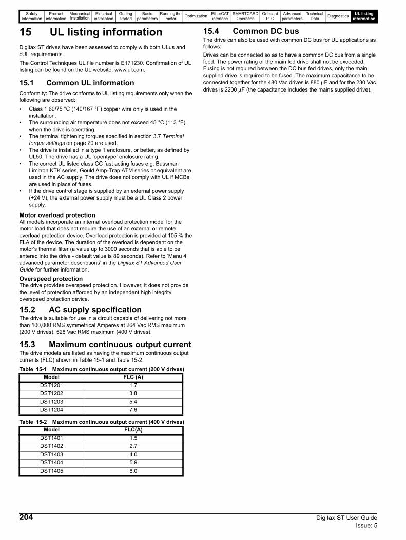
Safety Information
Product information
Mechanical installation
Electrical installation
Getting started
Basic parameters
Running the motor Optimization EtherCAT
interfaceSMARTCARD
OperationOnboard
PLCAdvanced
parametersTechnical
Data Diagnostics UL listing information
15 UL listing informationDigitax ST drives have been assessed to comply with both ULus and cUL requirements.The Control Techniques UL file number is E171230. Confirmation of UL listing can be found on the UL website: www.ul.com.
15.1 Common UL informationConformity: The drive conforms to UL listing requirements only when the following are observed:• Class 1 60/75 °C (140/167 °F) copper wire only is used in the
installation.• The surrounding air temperature does not exceed 45 °C (113 °F)
when the drive is operating.• The terminal tightening torques specified in section 3.7 Terminal
torque settings on page 20 are used.• The drive is installed in a type 1 enclosure, or better, as defined by
UL50. The drive has a UL ‘opentype’ enclosure rating.• The correct UL listed class CC fast acting fuses e.g. Bussman
Limitron KTK series, Gould Amp-Trap ATM series or equivalent are used in the AC supply. The drive does not comply with UL if MCBs are used in place of fuses.
• If the drive control stage is supplied by an external power supply (+24 V), the external power supply must be a UL Class 2 power supply.
Motor overload protectionAll models incorporate an internal overload protection model for the motor load that does not require the use of an external or remote overload protection device. Overload protection is provided at 105 % the FLA of the device. The duration of the overload is dependent on the motor's thermal filter (a value up to 3000 seconds that is able to be entered into the drive - default value is 89 seconds). Refer to ‘Menu 4 advanced parameter descriptions’ in the Digitax ST Advanced User Guide for further information.
Overspeed protectionThe drive provides overspeed protection. However, it does not provide the level of protection afforded by an independent high integrity overspeed protection device.
15.2 AC supply specificationThe drive is suitable for use in a circuit capable of delivering not more than 100,000 RMS symmetrical Amperes at 264 Vac RMS maximum (200 V drives), 528 Vac RMS maximum (400 V drives).
15.3 Maximum continuous output current The drive models are listed as having the maximum continuous output currents (FLC) shown in Table 15-1 and Table 15-2.
Table 15-1 Maximum continuous output current (200 V drives)
Table 15-2 Maximum continuous output current (400 V drives)
15.4 Common DC busThe drive can also be used with common DC bus for UL applications as follows: - Drives can be connected so as to have a common DC bus from a single feed. The power rating of the main fed drive shall not be exceeded. Fusing is not required between the DC bus fed drives, only the main supplied drive is required to be fused. The maximum capacitance to be connected together for the 480 Vac drives is 880 μF and for the 230 Vac drives is 2200 μF (the capacitance includes the mains supplied drive).
Model FLC (A)DST1201 1.7DST1202 3.8DST1203 5.4DST1204 7.6
Model FLC(A)DST1401 1.5DST1402 2.7DST1403 4.0DST1404 5.9DST1405 8.0
204 Digitax ST User Guide Issue: 5

Safety Information
Product information
Mechanical installation
Electrical installation
Getting started
Basic parameters
Running the motor Optimization EtherCAT
interfaceSMARTCARD
OperationOnboard
PLCAdvanced
parametersTechnical
Data Diagnostics UL listing information
15.5 DC Supplied driveThe drive can also have DC feed for UL applications as follows: - Supply connected to -DC and +DC terminals.
Table 15-3 DC fusing
In the table above, Ferraz xx may be 00 (fuse with no trip indicator installed) or 21 (fuse installed with trip indicator).
15.6 UL listed accessories
Model Volts DC nominal
Fuse current rating R/C JFHR2 fuse manufacturer, type, Amps
DST1201 340 25 Ferraz, 6,9xx CP GRC, 25 Siba URZ14x51 gR 690, 25DST1202 340 32 Ferraz, 6,9xx CP GRC, 32 Siba URZ14x51 gR 690, 40DST1203 340 40 Ferraz, 6,9xx CP GRC, 40 Siba URZ14x51 gR 690, 40DST1204 340 50 Ferraz, 6,9xx CP GRC, 50 Siba URZ14x51 gR 690, 50DST1401 680 25 Ferraz, 6,9xx CP GRC, 25 Siba URZ14x51 gR 690, 25DST1402 680 25 Ferraz, 6,9xx CP GRC, 25 Siba URZ14x51 gR 690, 25DST1403 680 25 Ferraz, 6,9xx CP GRC, 25 Siba URZ14x51 gR 690, 25DST1404 680 25 Ferraz, 6,9xx CP GRC, 25 Siba URZ14x51 gR 690, 25DST1405 680 25 Ferraz, 6,9xx CP GRC, 25 Siba URZ14x51 gR 690, 25
NOTE
• Digitax ST Keypad • SM-PROFIBUS-DP-V1• Digitax ST Braking resistor • SM-DeviceNet• SM-Keypad Plus • SM-I/O Timer• SM-I/O Plus • SM-CAN• SM-Ethernet • SM-INTERBUS• SM-CANopen • SM-Applications Lite• SM-Universal Encoder Plus • SM-Applications Lite V2• SM-Resolver • SM-SLM• SM-Encoder Plus • SM-Applications• SM-I/O Lite • SM-I/O PELV• SM-I/O 120V • SM-I/O 24V Protected• SM-LON • SM-I/O 32• SM-Applications Plus • SM-SERCOS• 15-way D-type converter • SM-I/O Timer• SM-Encoder Output Plus • SM-EtherCAT• SM-LON
Digitax ST User Guide 205Issue: 5
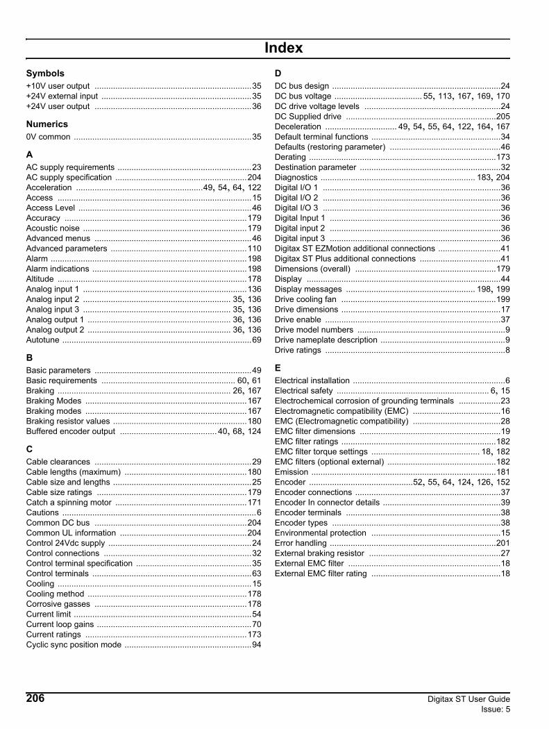
IndexSymbols+10V user output ....................................................................35+24V external input .................................................................35+24V user output ....................................................................36
Numerics0V common .............................................................................35
AAC supply requirements ..........................................................23AC supply specification .........................................................204Acceleration .......................................................49, 54, 64, 122Access ....................................................................................15Access Level ...........................................................................46Accuracy ...............................................................................179Acoustic noise .......................................................................179Advanced menus ....................................................................46Advanced parameters ...........................................................110Alarm .....................................................................................198Alarm indications ...................................................................198Altitude ..................................................................................178Analog input 1 .......................................................................136Analog input 2 ................................................................ 35, 136Analog input 3 ................................................................ 35, 136Analog output 1 .............................................................. 36, 136Analog output 2 .............................................................. 36, 136Autotune ..................................................................................69
BBasic parameters ....................................................................49Basic requirements .......................................................... 60, 61Braking ........................................................................... 26, 167Braking Modes ......................................................................167Braking modes ......................................................................167Braking resistor values ..........................................................180Buffered encoder output .......................................... 40, 68, 124
CCable clearances ....................................................................29Cable lengths (maximum) .....................................................180Cable size and lengths ............................................................25Cable size ratings .................................................................179Catch a spinning motor .........................................................171Cautions ....................................................................................6Common DC bus ..................................................................204Common UL information .......................................................204Control 24Vdc supply ..............................................................24Control connections ................................................................32Control terminal specification ..................................................35Control terminals .....................................................................63Cooling ....................................................................................15Cooling method .....................................................................178Corrosive gasses ..................................................................178Current limit .............................................................................54Current loop gains ...................................................................70Current ratings ......................................................................173Cyclic sync position mode .......................................................94
DDC bus design .........................................................................24DC bus voltage ...................................... 55, 113, 167, 169, 170DC drive voltage levels ...........................................................24DC Supplied drive .................................................................205Deceleration ............................... 49, 54, 55, 64, 122, 164, 167Default terminal functions ........................................................34Defaults (restoring parameter) ................................................46Derating .................................................................................173Destination parameter .............................................................32Diagnostics ................................................................... 183, 204Digital I/O 1 .............................................................................36Digital I/O 2 .............................................................................36Digital I/O 3 .............................................................................36Digital Input 1 ..........................................................................36Digital input 2 ..........................................................................36Digital input 3 ..........................................................................36Digitax ST EZMotion additional connections ...........................41Digitax ST Plus additional connections ...................................41Dimensions (overall) .............................................................179Display ....................................................................................44Display messages ........................................................ 198, 199Drive cooling fan ...................................................................199Drive dimensions .....................................................................17Drive enable ............................................................................37Drive model numbers ................................................................9Drive nameplate description ......................................................9Drive ratings ..............................................................................8
EElectrical installation ..................................................................6Electrical safety .................................................................. 6, 15Electrochemical corrosion of grounding terminals ..................23Electromagnetic compatibility (EMC) ......................................16EMC (Electromagnetic compatibility) ......................................28EMC filter dimensions .............................................................19EMC filter ratings ...................................................................182EMC filter torque settings ............................................... 18, 182EMC filters (optional external) ...............................................182Emission ................................................................................181Encoder .............................................52, 55, 64, 124, 126, 152Encoder connections ...............................................................37Encoder In connector details ...................................................39Encoder terminals ...................................................................38Encoder types .........................................................................38Environmental protection ........................................................15Error handling ........................................................................201External braking resistor .........................................................27External EMC filter ..................................................................18External EMC filter rating ........................................................18
206 Digitax ST User Guide Issue: 5
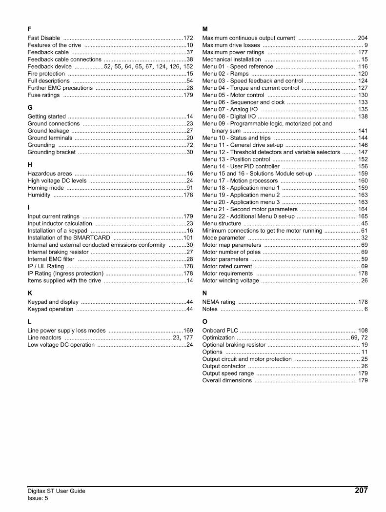
FFast Disable ..........................................................................172Features of the drive ...............................................................10Feedback cable .......................................................................37Feedback cable connections ...................................................38Feedback device ..................52, 55, 64, 65, 67, 124, 126, 152Fire protection .........................................................................15Full descriptions ......................................................................54Further EMC precautions ........................................................28Fuse ratings ..........................................................................179
GGetting started .........................................................................14Ground connections ................................................................23Ground leakage .......................................................................27Ground terminals .....................................................................20Grounding ...............................................................................72Grounding bracket ...................................................................30
HHazardous areas .....................................................................16High voltage DC levels ............................................................24Homing mode ..........................................................................91Humidity ................................................................................178
IInput current ratings ..............................................................179Input inductor calculation ........................................................23Installation of a keypad ...........................................................16Installation of the SMARTCARD ...........................................101Internal and external conducted emissions conformity ...........30Internal braking resistor ...........................................................27Internal EMC filter ...................................................................28IP / UL Rating ........................................................................178IP Rating (Ingress protection) ................................................178Items supplied with the drive ...................................................14
KKeypad and display .................................................................44Keypad operation ....................................................................44
LLine power supply loss modes ..............................................169Line reactors .................................................................. 23, 177Low voltage DC operation .......................................................24
MMaximum continuous output current .................................... 204Maximum drive losses .............................................................. 9Maximum power ratings ....................................................... 177Mechanical installation ........................................................... 15Menu 01 - Speed reference .................................................. 116Menu 02 - Ramps ................................................................. 120Menu 03 - Speed feedback and control ................................ 124Menu 04 - Torque and current control .................................. 127Menu 05 - Motor control ....................................................... 130Menu 06 - Sequencer and clock ........................................... 133Menu 07 - Analog I/O ........................................................... 135Menu 08 - Digital I/O ............................................................. 138Menu 09 - Programmable logic, motorized pot and binary sum ...................................................................... 141Menu 10 - Status and trips ................................................... 144Menu 11 - General drive set-up ............................................ 146Menu 12 - Threshold detectors and variable selectors ......... 147Menu 13 - Position control .................................................... 152Menu 14 - User PID controller .............................................. 156Menu 15 and 16 - Solutions Module set-up .......................... 159Menu 17 - Motion processors ............................................... 160Menu 18 - Application menu 1 .............................................. 159Menu 19 - Application menu 2 .............................................. 163Menu 20 - Application menu 3 .............................................. 163Menu 21 - Second motor parameters ................................... 164Menu 22 - Additional Menu 0 set-up ..................................... 165Menu structure ........................................................................ 45Minimum connections to get the motor running ...................... 61Mode parameter ..................................................................... 32Motor map parameters ........................................................... 69Motor number of poles ............................................................ 69Motor parameters ................................................................... 59Motor rated current ................................................................. 69Motor requirements .............................................................. 178Motor winding voltage ............................................................. 26
NNEMA rating ......................................................................... 178Notes ........................................................................................ 6
OOnboard PLC ........................................................................ 108Optimization ......................................................................69, 72Optional braking resistor ......................................................... 19Options ................................................................................... 11Output circuit and motor protection ........................................ 25Output contactor ..................................................................... 26Output speed range .............................................................. 179Overall dimensions ............................................................... 179
Digitax ST User Guide 207Issue: 5

PParameter access level ...........................................................46Parameter ranges .................................................................113Parameter security ..................................................................46Parameter x.00 .......................................................................54Planning the installation ..........................................................15Position feedback ....................................................................60Position feedback module category parameters ...................159Power cables ..........................................................................37Power ratings ........................................................................173Power terminal connections ....................................................22Precision reference Analog input 1 .........................................35Product information ...................................................................8QQuick Start set-up ...................................................................64
RRamps .....................................................................................54Ratings ....................................................................................25Recommended cable management ........................................29Relay contacts ........................................................................37Resolution .............................................................................179RJ45 connector - connection details .......................................32RoHS compliance .................................................................178Routine maintenance ..............................................................20Running the motor ..................................................................60
SSAFE TORQUE OFF ..............................................................42SAFE TORQUE OFF/drive enable .........................................37Safety information ...................................................................15Saving parameters ..................................................................46Serial comms lead ..................................................................32Serial communications connections ........................................31Serial communications look-up table ....................................197Serial communications port isolation ......................................32Single line descriptions ...........................................................49SMARTCARD codes .............................................................102SMARTCARD data blocks ....................................................102SMARTCARD Operation ......................................................101SMARTCARD parameters ....................................................104SMARTCARD trips ...............................................................106Solution module identification .................................................72Solutions Module ....................................................................11Solutions Module / keypad installation / removal ....................16Source parameter ...................................................................32Speed and position feedback ..................................................60Speed limits ............................................................................54Speed loop gains ....................................................................71Speed reference selection ......................................................54Start up time ..........................................................................179Starts per hour ......................................................................179Status ............................................................................. 45, 199Status indications ..................................................................199Status information ...................................................................59Stop modes ...........................................................................169Storage .................................................................................178Supply requirements .............................................................177Supply types ...........................................................................23SYPTLite ...............................................................................108
TTechnical data .......................................................................173Temperature ..........................................................................178Terminal torque settings ..........................................................20Torque modes .......................................................................168Trip ........................................................................................183Trip categories ......................................................................198Trip indications ......................................................................183Typical pulse duty .................................................................173
UUL listed accessories ............................................................205UL listing information .............................................................204Use of residual current device (RCD) .....................................27User security ...........................................................................47
VVariable maximums ...............................................................113Vibration ................................................................................178
WWarnings ...................................................................................6Weight ...................................................................................179Writing to the SMARTCARD .................................................102
208 Digitax ST User Guide Issue: 5

EPA GmbHFliederstraße 8, D-63486 BruchköbelDeutschland / GermanyTelefon / Phone: +49 (0) 6181 9704 - 0Telefax / Fax: +49 (0) 6181 9704 - 99E-Mail: [email protected]: www.epa.de
Brands – business names – work titlesCompany and product names used by EPA are used only for labeling and are mentioned without taking into account any commercial protection right; the lack of the marking of a possibly existent commercial protection right does not mean that the used company and /or product name is available. The EPA logo is a registered trademark for the EPA GmbH. All rights reserved. Technical changes without notice. Release: 5-09.2015 Order no.: 50275639
All
info
rmat
ion
with
out l
iabi
lity
for
corr
ectn
ess
and
accu
racy
.
Presented by: