digital receiver ar-dv10 · introduction thank you for purchasing the ar-dv10. ar-dv10 is the...
TRANSCRIPT

®
DIGITAL RECEIVER
AR-DV10 Operating manual
AOR, Ltd. Authority On Radio Communications
Stay up to date! Operating manual addendum and firmware updates available at http://www.aorja.com/receivers/ar-dv10.html

.]

INTRODUCTION Thank you for purchasing the AR-DV10.
AR-DV10 is the world's most advanced multi-mode, SDR hand-held receiver that supports a
variety of digital, as well as analog modes.
Enjoy multi-digital signal monitoring on the go!
Some of its outstanding features are:
1) Wideband reception 100kHz - 1300MHz
2) Multi-mode digital demodulation (automatic detection except for Tetra)
3) All-mode analog reception
4) Fast Memory Scan
5) Fast Program Search
6) Receiving support functions (such as step-adjustment, offset and priority reception)
7) MicroSD card support (recording, memory data input/output, firmware updates)
8) Dedicated radio IC for 520kHz - 1710kHz AM and 64MHz - 108MHz FM broadcasts.
9) Supplied accessories: Large capacity Lithium-ion battery pack, AC power adapter,
alkaline battery tray, cigarette lighter DC/DC converter, fast charger cradle.
10) IPX5 water resistant (providing the antenna, battery pack, belt clip, and all rubber
covers are firmly attached)
11) 2.56” (W) x 5.40” (H) x 1.61” (D) (65 mm x 137 mm x 41 mm) compact design.
Please read this operating manual carefully. This information will allow you to enjoy
maximum performance from your receiver.
We sincerely hope that the AR-DV10 will be your monitoring companion for many years to
come.
All product names referenced herein are trademarks of their respective manufacturers.
Marks such as TM and ® symbols are omitted in the body of the text.
AOR, Ltd.

2
TABLE OF CONTENTS
SAFETY PRECAUTIONS ............................................................................................... 4
1. SUPPLIED ITEMS...................................................................................................... 5
2. CONTROLS & CONNECTORS ................................................................................. 6
2.1. TOP PANEL ............................................................................................................. 6
2.2. FRONT PANEL ........................................................................................................ 6
2.3. LEFT SIDE .............................................................................................................. 7
2.4. RIGHT SIDE ............................................................................................................ 7
2.5. REAR PANEL .......................................................................................................... 8
2.6. BOTTOM PANEL ..................................................................................................... 8
2.7. LCD DISPLAY ......................................................................................................... 9
3. POWER SUPPLY ..................................................................................................... 13
3.1. BATTERY PACK INSTALLATION & REMOVAL .................................................... 13
3.2. BATTERY PACK CHARGING................................................................................ 14
3.3. POWERING WITH ALCALINE BATTERIES .......................................................... 15
3.4. POWERING WITH CIGARETTE LIGHTER DC/DC CONVERTER ....................... 16
4. ANTENNA ................................................................................................................ 17
4.1 EARPHONE ANTENNA ......................................................................................... 17
5. BASIC OPERATION ................................................................................................ 18
5.1. POWER ON/OFF .................................................................................................. 18
5.2. VOLUME ............................................................................................................... 18
5.3. VFO MODE RECEPTION ..................................................................................... 19
5.4. FREQUENCY INPUT ............................................................................................ 19
5.5. RECEIVE MODE SELECTION .............................................................................. 20
5.6. IF BANDWIDTH SELECTION ............................................................................... 21
5.7. SQUELCH ............................................................................................................. 21
5.8. TUNING STEP ...................................................................................................... 22
5.9. STEP-ADJUST ...................................................................................................... 23
6. AUDIO RECORDING ............................................................................................... 25
6.1. FILE FORMAT ....................................................................................................... 25
6.2. RECORDING DURATION ..................................................................................... 25
6.3. RECORDING START/STOP.................................................................................. 25
6.4. PLAYBACK ............................................................................................................ 26
6.5. SD CARD FORMATTING ...................................................................................... 26
7. MEMORY CHANNEL & SCAN OPERATIONS ........................................................ 27
7.1. SAVE A FREQUENCY INTO A MEMORY CHANNEL ........................................... 27
7.2. SCAN A MEMORY BANK ...................................................................................... 28

3
7.3. SCAN PASS .......................................................................................................... 30
7.4. BROWSE MEMORY BANKS/CHANNELS ............................................................ 30
7.5. EDIT A MEMORY CHANNEL ................................................................................ 31
7.6. ASSIGN TITLES TO MEMORY BANKS ................................................................ 32
7.7. CREATE A GROUP OF LINKED MEMORY BANKS ............................................. 32
7.8. SCAN A GROUP OF LINKED MEMORY BANKS.................................................. 34
7.9. COPY/ERASE/MOVE CHANNELS, BANKS AND GROUPS ................................ 34
8. PRIORITY RECEPTION ........................................................................................... 35
9. PROGRAM SEARCH ............................................................................................... 36
9.1. CREATE A SEARCH BANK................................................................................... 36
9.2. RUN A SEARCH .................................................................................................... 37
9.3. SEARCH PASS ..................................................................................................... 38
9.4. CREATE A GROUP OF LINKED SEARCH BANKS .............................................. 39
9.5. SEARCH A GROUP OF LINKED SEARCH BANKS .............................................. 40
9.6. COPY/ERASE/MOVE SEARCH BANKS, GROUPS AND PASS FREQ. ............... 40
10. ADVANCED OPERATION...................................................................................... 42
10.1. SIGNAL ATTENUATOR ....................................................................................... 42
10.2. AGC ..................................................................................................................... 42
10.3. INPUT CHARACTERS & SYMBOLS .................................................................. 43
10.4. DATA EDITOR (COPY, MOVE, DELETE) ............................................................ 44
10.5. ADVANCED SQUELCH TYPES .......................................................................... 45
10.5.1. CTCSS & REVERSE TONE ............................................................................. 45
10.5.2. DCS .................................................................................................................. 46
10.6. ANALOG VOICE DESCRAMBLER ..................................................................... 47
10.7. ADVANCED DIGITAL MODE SETTINGS ............................................................ 47
10.8. OFFSET RECEPTION ........................................................................................ 49
10.9. REMOTE MODE ................................................................................................. 49
11. RECEIVER SETTINGS .......................................................................................... 50
11.1. CALENDAR & CLOCK ........................................................................................ 50
11.2. SYSTEM SETTINGS ........................................................................................... 50
12. RECEIVER DATA BACKUP & RESTORE ............................................................. 53
13. FIRMWARE UPDATE ............................................................................................ 55
14. TROUBLESHOOTING ........................................................................................... 57
15. SPECIFICATIONS .................................................................................................. 59

4
SAFETY PRECAUTIONS
• Do not use any other power adapter than the one supplied with the receiver. Only the
supplied power adapter is tested and approved for use with this receiver. Using
un-approved power adapters may cause smoke, fire, or battery to damage.
• Do not listen with earphones at high volume levels. If you experience a ringing in your
ears, reduce the volume level or discontinue use.
• Do not operate the receiver in a wet environment unless the flexible rubber antenna,
battery pack, belt-clip and all rubber covers are securely attached to the receiver. Be
sure the battery pack is dry before attaching it. Exposing the inside of the receiver to
water can result in serious damage to the receiver. In case the battery pack has been
exposed to water, immediately dry the contacts completely before attaching it again to
the receiver.
• Do not operate the receiver while driving a vehicle, as an accident may occur.
• Do not use harsh solvents such as alcohol or benzene to clean the receiver, as it is
likely to damage the receiver’s surfaces. If the receiver became dirty, wipe it clean with a
soft, dry cloth.
• Do not leave the receiver in direct sunlight for an extended time, or in areas with
temperatures below –10°C or over +60°C.
• This receiver meets IPX5 requirements for waterproof protection. However, after the
receiver has been dropped or opened by an unauthorized person, waterproof protection
cannot be guaranteed because of possible damage to the receiver’s case or waterproof
seal.
Special precautions regarding the supplied lithium-ion battery pack:
• Do not short the battery pack terminals. A short may occur if the terminals touch metal
objects, therefore, be cautious when placing the battery pack in a pocket or bag. A short
may damage the battery pack, and also constitutes a potential fire hazard.
• Do not expose the battery pack terminals to any liquid. Do not charge or use a wet
battery pack.
• Do not attempt to open or impact the battery pack, or solder the terminals, as this may
cause liquid leakage, fire hazard, damage and personal injury.
• Never expose the battery pack to temperatures higher than +60°C such as in a vehicle
during hot seasons, as it could initiate a fire, or degrade the battery performance.
• Use only the supplied AOR battery pack with the supplied AOR power adapter. The
supplied power adapter is tested and approved for use with the supplied AOR battery
pack. Using unapproved battery packs or power adapters may cause smoke or fire; or
may cause the battery pack to burst. Recycling of the lithium-ion battery pack Lithium-ion batteries have an estimated life time of 300 to 500 charges, after which they become weak, even fully charged. Contact your local dealer to purchase a new battery pack and to obtain information on how lithium-ion batteries should be recycled in your country.
Li-ion 00

5
1. SUPPLIED ITEMS ・ AR-DV10 Digital Receiver (including antenna ring) ................................................. 1
・ AA-10* AC power adapter ................................................................................... 1
・ BP-10 Lithium-ion battery pack .......................................................................... 1
・ CC-10 Fast charger cradle ................................................................................. 1
・ BC-10 Belt clip .................................................................................................... 1
・ RA-10 Antenna ................................................................................................... 1
・ DC-10 Cigarette lighter DC/DC converter ........................................................... 1
・ BT-10 Alkaline battery tray ................................................................................. 1
・ microSD card ................................................................................................................ 1
・ Printed user manual ....................................................................................................... 1
(* The European version is AA-10E)

6
2. CONTROLS & CONNECTORS 2.1. TOP PANEL
(1) Antenna jack (BNC 50Ω)
Attach the supplied flexible antenna or connect an external antenna.
(2) Antenna ring
Covers the gap between the antenna and the jack. Remains on the jack when the antenna is removed.
(3) VOLUME (inner) knob
Turn this (inner) control clockwise to increase the volume and counterclockwise to decrease the volume.
(4) DIAL selector (outer) knob
Tunes the frequency up or down and selects menu items.
2.2. FRONT PANEL
(5) LCD (liquid crystal display)
Shows selected operating conditions, as described in chapter 2.7 “LCD DSPLAY”
(6) Cursor keys and [ENT] key
[ ] and [ ] are used to change the frequency or select an item displayed on the LCD. Press the [ENT] key to store the selection or entered values. The [ENT] key is also used to switch VFOs. Press and hold the [ENT] key to display the memory channel registration menu.
(7) [MENU] key
Displays the MENU-TOP screen.
(8) [MODE] key
Displays the receive modes menu.
(9) [ ] REC key
Starts/stops audio recording to the SD card.
(10) [CLR] key
Cancels the current operation or returns to parent menu.
(11) [ ] key lock
Press and hold to enable/disable the lock feature. When enabled, all controls except VOL and PWR will be disabled.
(12) Numeric keypad
The keypad is used when setting frequencies, bank & channel numbers, or entry selections in a menu.
(13) Loudspeaker

7
2.3. LEFT SIDE
(14) POWER switch
Press the switch briefly to turn the receiver ON. Press and hold it for 3 seconds to turn the receiver OFF.
(15) SQL/MONI (squelch/monitor) switch
Press to enable the squelch value to be adjusted with the DIAL. Press again to validate and save the setting.
Press and hold this button to open the squelch manually, to listen for weak signals. That is the MONITOR function.
(16) microSD card slot
Lift the rubber cover to install the supplied SD card. The SD card is used for audio recording & playback. The card is also used to backup and restore memories, memory banks, system & CSV data, as well as to install firmware updates.
All rubber covers must be closed and the battery pack installed for the receiver to be waterproof (IPX5).
2.4. RIGHT SIDE
(17) EARPHONES jack (3 pin 3.5mm, mono output) Lift the rubber cover to connect earphones. A menu setting allows the earphone cable to act as an antenna for FM Broadcast band (64 - 107.99999MHz, 100kHz IF bandwidth only).
(18) DATA jack (USB mini-B socket) Lift the rubber cover to connect a USB cable for command control. (No AOR software supplied.)
(19) EXT DC jack
To power the receiver from an external source, connect either the supplied AC power adapter or the cigarette lighter DC/DC converter.
For safety reasons, use only the supplied power
devices.

8
2.5. REAR PANEL
(20) Belt clip screw holes
Mount the belt clip here using the 2 supplied screws. When the belt clip is not used, it is important to affix the screws to the body to prevent water entering these holes.
(21) Belt clip
(22) Battery pack
Only use the supplied lithium-ion battery pack. Be sure the rubber gasket is properly seated when inserting the battery pack.
All rubber covers must be closed and the battery pack installed for the receiver to be waterproof (IPX5).
2.6. BOTTOM PANEL
(23) Battery pack latch
(24) Locking plate (grey color) To install the battery pack: Insert the battery in the battery compartment, press the end of the battery latch on the bottom of the receiver, then lock the pack by sliding the locking plate beside the latch until the entire “LOCK” appears. To remove the battery pack: Turn the receiver off, slide the locking plate until “UNLOCK” appears entirely, lift the end of the battery up, by pressing the battery latch, then remove the battery from the receiver.

9
2.7. LCD DISPLAY
Section Icons
1
Key lock status All controls except VOL and PWR are disabled. Press and hold to enable/disable the lock feature.
Remote control status All controls except VOL and PWR are disabled. Press the ENT key to stop remote control.
[REC] Currently recording on SD card. Press the [] key to toggle recording ON or OFF.
Battery status : Fully charged 〜 : Partially full
: Battery almost empty (urgently recharge the battery) : charging* : Running on external power*
(*: Not displayed when charging through the charger cradle) 12:34:56
Time (HH:MM:SS in 24 hour format)
1 →
2 →
3 →
4 →
5 →
6 →
7 →

10
2
[VFO] Operation mode
[VFO]: VFO
[MEM]: Memory channel readout
[SCN]: Scan
[SER]: Search FM15
Demodulation modes (IF bandwidth in kHz or Hz): FM100, FM30, FM15, FM6 (kHz) AM15, AM8, AM5.5, AM3.8 (kHz) USB2.6, USB1.8, LSB2.6, LSB1.8 (kHz) CW500, CW200 (Hz)
IF bandwidths for digital modes: FM30, FM15, FM6 (kHz)
[D] Digital demodulation is activated.
YAES Digital mode which has been set manually, or which has been automatically detected by the receiver:
YAES: YAESU (C4FM) DSTR: D-STAR DMR: DMR (Tier 1 / Tier 2 / MOTOTRBO) D-CR: Japanese D-CR & NXDN (6.25k) dPMR: dPMR (446 Tier 1) ALIN: ALINCO (EJ47U) P-25: APCO25 (Phase 1) T-DM: TETRA (Direct mode, mobile to mobile)
[Au] Auto-detection of digital modes is activated. (Except Tetra)
20k
Frequency step in kHz. Step-adjust values (when activated) are shown in Section 5.8
3
VFO-A XXXX.XXX XX VFO-B XXXX.XXX XX
------------------- 00-00 XXXX.XXX XX BANK.T (bank title) CH.T (channel title) 00 XXXX.XXX XX BANK.T (bank title)
Receive frequency (In MHz over 3MHz and in kHz below 3MHz. The currently received VFO is shown on the upper line.
---------------------- For memory channel readout and scan modes, the bank and channel numbers are displayed on the upper line. The bank and channel titles are on the lower line. For search mode, the bank number is displayed on the upper line. The bank title is on the lower line.
Memory channel readout mode Search mode
UPPER SIDE→
LOWER SIDE→

11
4
[B] BUSY (The squelch is open)
S-Meter signal strength meter (relative signal strength). Relative signal strength of incoming signal is indicated in standard S units, from S1 to S9. Calibration above S9 is in dB up to +60dB.
microSD card Solid: Card ready Blinking: Checking, please wait.
5
NSQ:nnn (or LSQ) Adj: 10k DUP Others: VolATT CTC DCS RTN VI AGCF AGCM AGCS RF-G ATT EAR PAS
Noise squelch set at level nnn Level squelch set at level nnn Frequency step adjustment value Offset frequency is active Volume attenuator is active CTCSS squelch is active DCS squelch is active Reverse tone squelch is active Analog voice descrambler is active (not available for US consumer version.) Automatic gain control “fast” is set Automatic gain control “mid” is set Automatic gain control “slow” is set Manual gain control is set Signal attenuator is ON The earphones cable acts as an antenna for FM (64-107.99999MHz, IF bandwidth 100kHz only) Frequency pass is on.
6
from CCCCCC /3 to CQCQCQ rep1 CCCCCC C rep2 CCCCCC C
Details on incoming signal. Type of information is mode de-pendent.
7
[ ] [ A< - >B ] [ ] Each of the three black rectangles can appear as following:
Select with physical [], [ENT] and [] buttons below the display.
Move left or lower the frequency (by 10 times the set step).
Move right or increase the frequency (by 10 times the set step).
A<->B Switch between VFO-A and VFO-B.
ENT Validate an input
Move up one line
Move down one line
Return to previous screen
BS Delete the last character entry
C Move to left digit
C Move to right digit
SEL Selection
SET Settings
SET& Set and return to previous screen

12
NEXT Go to next
S<->Z Toggle between search, scan and VFO.
COPY Copy date and time information

13
3. POWER SUPPLY
CAUTION REGARDING THE LITHIUM-ION BATTERY PACK.
・ Do not leave the charger connected to the receiver for continuous periods in excess of 24 hours. Long term overcharging can degrade the lithium-ion battery pack and significantly shorten its useful life.
・ A complete discharge of the battery is likely to shorten its useful life. ・ The receiver standby mode consumes some battery power even when the receiver is
switched OFF. If the receiver is unused for over a month, to prevent over-discharge of the battery, either remove the battery pack from the receiver or charge the battery every month.
・ If the battery is stored outside of the receiver for an extended period of time, it should be charged for about 2 hours once every 6 months to prevent over-discharge.
・ The battery pack can be charged approximately 300 times; however, over-charging or discharging it might reduce this number.
Do not attempt to open the battery pack as personal injury or damage to the lithium-ion cells could occur if they become accidentally short-circuited. 3.1. BATTERY PACK INSTALLATION & REMOVAL INSTALLATION
1. Insert the battery into the battery compartment and then press the battery latch on the bottom of the receiver onto the battery catch.
2. Slide the locking plate up beside the latch, until “LOCK” appears beneath the latch. 3. The receiver will power ON automatically. To switch it OFF, simply press the red power
button for 3 seconds. REMOVAL
1. Turn the receiver OFF. 2. Slide the locking down plate until “UNLOCK” appears beneath the latch. 3. Release the battery latch and Lift the end of the battery upward from the compartment,
then remove the battery from the receiver.
Battery pack latch
Locking plate (grey color)
Slide down to unlock
Slide up to lock
Rubber gasket must
not be loose.
BP-10
14
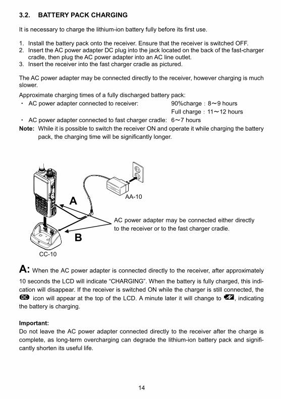
3.2. BATTERY PACK CHARGING It is necessary to charge the lithium-ion battery fully before its first use. 1. Install the battery pack onto the receiver. Ensure that the receiver is switched OFF. 2. Insert the AC power adapter DC plug into the jack located on the back of the fast-charger
cradle, then plug the AC power adapter into an AC line outlet. 3. Insert the receiver into the fast charger cradle as pictured.
The AC power adapter may be connected directly to the receiver, however charging is much slower.
Approximate charging times of a fully discharged battery pack:
・ AC power adapter connected to receiver: 90%charge:8~9 hours
Full charge:11~12 hours
・ AC power adapter connected to fast charger cradle: 6〜7 hours
Note: While it is possible to switch the receiver ON and operate it while charging the battery
pack, the charging time will be significantly longer.
A: When the AC power adapter is connected directly to the receiver, after approximately
10 seconds the LCD will indicate “CHARGING”. When the battery is fully charged, this indi-
cation will disappear. If the receiver is switched ON while the charger is still connected, the
icon will appear at the top of the LCD. A minute later it will change to , indicating
the battery is charging.
Important:
Do not leave the AC power adapter connected directly to the receiver after the charge is
complete, as long-term overcharging can degrade the lithium-ion battery pack and signifi-
cantly shorten its useful life.
AC power adapter may be connected either directly
to the receiver or to the fast charger cradle.
A
B
AA-10
CC-10

15
B: If the AC power adapter is connected to the fast charger cradle, when the receiver is
inserted into the cradle, the cradle’s LED will first turn red, indicating a charging status. When the battery pack is fully charged, the LED will turn green. A flashing red LED indicates a charging error. If this occurs, please check the following: ・ Inspect the battery pack and charger cradle electrodes for any contamination or
obstructive object. ・ The battery pack might be over-discharged. A totally discharged battery pack cannot be
charged using the cradle. In that case connect the AC power adapter directly to the receiver to charge the battery pack for about 10 minutes. Then continue the charge as usual through the charger cradle.
3.3. POWERING WITH ALCALINE BATTERIES
The supplied alkaline battery tray allows operation of the receiver using six “AA” size alkaline battery cells.
Important::::
・ The battery tray must NOT be used with rechargeable cells, as it does not contain the thermal and over-current protection circuits required when utilizing Ni-Cd and Ni-MH cells! When installing the alkaline batteries, insert the (-) end first, then press in the (+) end so the battery snaps into place. Pay attention to the polarity indicated inside the tray.
Insert (-) ends first.
Alkaline battery tray BT-10

16
3.4. POWERING WITH CIGARETTE LIGHTER DC/DC CONVERTER With the supplied cigarette lighter DC/DC converter (DC-10), A vehicle's cigarette lighter socket (12V or 24V) may be used as the power source. Important::::
・ Do not connect any accessory not approved by AOR to supply DC power; otherwise the receiver may be damaged.
・ The AOR cigarette lighter DC/DC converters supplied for other AOR receivers are not compatible with the AR-DV10.
Insert this end to the vehicle’s
cigarette lighter socket.
Insert the DC plug firmly into the
receiver’s EXT-DC socket
DC-10

17
4. ANTENNA The AR-DV10 is supplied with a flexible rubber antenna to be attached to the 50 Ohm BNC jack located on the top of the receiver.
Note:
・ AR-DV10 does not feature any internal AM ferrite antenna. ・ Due to physical limitations, the supplied flexible rubber antenna is not ideal for reception
of LW, MW or SW. Although it does work to some extent, a dedicated external antenna should be connected for optimal reception of those bands. However, the receiver RF stage is extremely sensitive, if a signal is too strong, it could potentially overload the RF stage. Therefore, it is highly advised to use an external antenna signal attenuator when connecting to an external antenna.
ANTENNA INSTALLATION
1. Make sure that the antenna ring is in place.
2. Align the slots of the antenna connector to the pins of the antenna jack. 3. Rotate the antenna connector clockwise ¼ turn to lock the mechanism.
・ To remove the flexible antenna, rotate the antenna counterclockwise ¼ turn to unlock the mechanism.
The antenna ring fills the gap between the antenna and the jack. It should remain on the jack when the antenna is removed. The ring does not fulfill any waterproof function.
4.1. EARPHONE ANTENNA When the earphone antenna cable function is activated, the cable acts as an antenna for the FM Broadcast band (64-107.99999MHz, IF bandwidth 100kHz only). 1. Press [MENU] → use the cursor key [] to select
[OPT]and press [ENT]. 2. Use the cursor key [] to select [EAR ANT] and, then
press [ENT]. 3. Select ON or OFF by rotating the DIAL selector knob. 4. Press [ENT] twice. When set to ON, [EAR] will be displayed on the main screen.
Flexible antenna
Antenna ring
Antenna jack
RA-10

18
5. BASIC OPERATION 5.1. POWER ON/OFF To power the receiver ON, briefly press the red power button. The boot sequence will start when the button is released, it takes about 3 seconds for the receiver to be ready for operation. To power the receiver OFF, press and hold the red power switch for 3 seconds. Release the button after 3 seconds, and the shutdown sequence will complete. It takes about 3 seconds for the receiver to completely shut down. During these 3 seconds, all receiver settings and the frequency data are saved in the receiver’s memory. Note: Do not suddenly interrupt the power supply, otherwise the receiver will not retain the
previously saved receiver settings and frequency data. 5.2. VOLUME Turn the volume (inner) knob clockwise to increase the volume and counterclockwise to decrease the volume. The volume knob controls the speaker & earphones volumes, as well as the key press, startup and error beep sound levels. However, the beep sound levels can be set individually as follows: 1. Press [MENU], use [] to select [CONF] and press [ENT] twice. 2. Using the DIAL knob, adjust the beep sound to the desired level between 00 (off) and 15
(max). 3. Press [ENT] to Validate the setting.
The maximum volume level can also be set as follows:
1. Press [MENU], use [] to select [CONF] and press [ENT].
2. Use [] to select [VOL ATT] and press [ENT].
3. Using the DIAL knob, adjust the volume level attenuation between 00 (maximum volume) and 15 (most attenuated). Default is level 5.
4. Validate with [ENT].

19
5.3. VFO MODE RECEPTION
The AR-DV10 has three VFOs, VFO-A, VFO-B and VFO-Z, each VFO has independent
receive frequency, demodulation mode, frequency step, etc.... settings. However only one
VFO can be selected and received at a time.
VFO currently being received
To select VFO-A:
Press [MENU] and [ENT] twice.
To select VFO-B:
Press [MENU] and [ENT]. Use [] to select VFO [B] and, then press [ENT].
To select VFO-Z:
Press [MENU] and [ENT]. Use [] to select VFO [Z] and, then press [ENT].
・Press [ENT] to switch between VFO-A and VFO-B.
5.4. FREQUENCY INPUT
In VFO mode there are 3 ways to adjust the frequency:
A) VIA THE KEYPAD
Directly enter the frequency in MHz with the keypad and validate with [ENT].
For example to set 439.49MHz:
[4] → [3] → [9] → [.] → [4] → [9] → [ENT]
For frequencies under 1MHz, start with [0], [.] or just [.].
To delete just one digit, use the [] key.
To cancel frequency input, press [CLR].

20
B) TURNING THE DIAL SELECTOR KNOB
Turn the dial selector knob on the top panel to select the desired operating frequency.
The step increment per knob click is according to the frequency step displayed at the
top right corner of the screen. (See chapter 5.8 “TUNING STEP” to change this step
value.)
C) USING THE [] and [] KEYS (fast tuning method)
Press [] to increase or [] to decrease the frequency.
The step increment per keypress is 10 times the frequency “TUNING STEP” step that is
displayed at the top right corner of the screen. (See chapter 5.8 “TUNING STEP” to
change this step value.)
5.5. RECEIVE MODE SELECTION
Press [MODE] and use the arrows [] or [] to select the desired receive mode and, then
press [ENT] to validate the entry.
The first page lists the digital modes: YAES: YAESU (C4FM) DSTR: D-STAR DMR: DMR (Tier 1 / Tier 2 / MOTOTRBO) D-CR: Japanese D-CR & NXDN (6.25k) dPMR: dPMR (446 Tier 1) ALIN: ALINCO (EJ47U) P-25: APCO25 (Phase 1) T-DM: TETRA (Direct mode, mobile to mobile) ・ When a digital mode is selected, the audio will be
muted until the receiver detects a signal of this mode. ・ Note that some restrictions apply for each mode.
The second page lists the analog modes with the exception of AUT1. AUT1 corresponds to automatic detection of the digital modes listed above, except Tetra. AUT1 is particularly useful when listening for digital signals, but don’t know in advance which kind of digital signals might be received. ・ Squelch remains open for AUT1; therefore, radio
noise will be heard, even when no actual digital mode signal is received.

21
5.6. IF BANDWIDTH SELECTION The appropriate IF bandwidth may to be set manually for each analog demodulation mode. However for digital modes, the IF bandwidth is automatically selected and cannot be changed. After the desired analog mode has been set, access the IF bandwidth menu as follows: 1. Long press [MODE] and use [ ] to select [IFBW],
followed by [ENT]. 2. Use the arrows [] or [] to select the desired bandwidth
and then press [ENT] to validate the setting. (Greyed out values cannot be selected.)
User selectable bandwidths for each of the analog modes: FM 6, 15, 30, 100 kHz AM 3.8, 5.5, 8, 15 kHz USB 1.8, 2.6 kHz LSB 1.8, 2.6 kHz CW 200, 500 Hz 5.7. SQUELCH The squelch function quiets the background “white” radio noise, when no signal is present. It operates in analog modes (FM, AM, USB, LSB, CW) and the digital auto-mode (AUT1). It has no effect for the individual digital modes (DSTR, YAES, DMR, D-CR(NXDN), dPMR, ALIN, P-25, T-DM) as the receiver only lets audio pass through when a digital signal is detected. The squelch can be manually “opened” and allow signals to be heard, or “closed” to mute the audio of the signal.
When the squelch is “open”, the indicator (for busy) appears on the left side of the LCD. When doing a memory SCAN or SEARCH, the squelch setting is very important as it serves as a receiver signal threshold to determine whether or not a signal is present, and when to resume scanning. Squelch type and threshold value example
Above example shows selectable bandwidths for AM mode.

22
Squelch is adjusted as follows: 1. Press the [SQL/MONI] switch on the left side of the receiver, that will select [NSQ:010]
as shown in the illustration on page 21. Rotate the DIAL knob selector to set the squelch threshold so that the receiver is just silenced. The squelch is now “closed” and no audio is heard.
2. Press [SQL/MONI] again to return to normal operation. Note: Do not set the squelch value too high, as a higher number indicates that a greater
signal level is required to open the squelch and weak signals will not be heard. Monitor function: The squelch can be temporarily opened by holding the [SQL/MONI] switch pressed. This is useful to listen for weak signals, where the signal level is close to the noise level. There are two types of analog squelch: NSQ (noise squelch) used for FM mode (including all digital modes). LSQ (level squelch) used for AM, LSB, USB, CW modes. The receiver automatically selects the appropriate squelch type for optimal performance. However, if needed the squelch type can be forced as follows: 1. Press [MENU], then press [ENT]. 2. Use [] to select [VFO EDIT], followed by [ENT] twice. 3. Rotate the dial knob to select NOISE or LEVEL. 4. Press [ENT] to validate the setting.
5. Activate the settings using [] to move to line 9, VFO
PARAM SET and press [ENT].
5.8. TUNING STEP
A tuning step is the rate the frequency will be incremented per click when rotating the dial
selector knob.
←Tuning step value

23
The tuning step value can be changed as follows:
1. Press [MENU], then press [ENT].
2. Use [] to select [STEP], then press [ENT].
←
3. Use the arrow keys [] or [] to select the desired step and press [ENT] to validate the
setting.
5.9. STEP-ADJUST
This function is useful when the array of desired receiver frequencies is not compatible with
the default step frequency. Step-adjust allows setting the frequency steps accordingly.
The following example describes a situation when a 20kHz frequency step needs to be ad-
justed to 10kHz steps.
The step-adjust value can be set as follows:
Press [MENU], then press [ENT].
Use [] to select [STEP ADJ], then press [ENT].
439.00 439.02 439.04 439.06 439.08 439.10
439.01 439.03 439.05 439.07 439.09
20kHz step
10kHz step-adjust
Note that there are 3 pages of values from 10Hz
up to 500kHz.
Note that there are 3 pages of values from
0.05kHz up to 250kHz. Select 0Hz to disable
the function.

24
Use the arrow keys [] or [] to select the desired value, then press [ENT] to validate the
setting.
Note: The maximum value which can be set, corresponds to half the frequency step set in
section 5.8 “TUNING STEP”.

25
6. AUDIO RECORDING The received audio can be recorded in MONO on a microSD card and played back.
Note:
・ When a microSD card is inserted, the receiver might take more or less time to read the
card’s content, depending on the size of the card. When the icon is still blinking, it
means that the receiver is currently reading the card. Once the icon is solid, the card is ready for operation.
・ If the icon does not appear on the LCD after the card has been inserted, either the card’s file format has not been recognized by the receiver, or the card’s terminals are dirty. Never remove the card while recording (when the [REC icon is lit) or when data is being written to the card. Interrupting data writing is likely to corrupt the card file system and loss of data can occur.
6.1. FILE FORMAT
・ Audio is recorded in WAV format, 16bits, 38400kHz, mono. ・ The resulting file names have 8 numerical digits, (ex. 00000001.wav). ・ Each new recording has a file number incremented by 1. (ex. 00000001.wav will be
followed by 00000002.wav). ・ If the file 99999999.wav is present on the SD card, a new recording cannot be made. ・ The .wav recordings can also be played back using the audio playback software of most
operating systems. However, the computer must have an SD card reader to accept the card.
6.2. RECORDING DURATION
・ Approx. three and half hours recording per GB. ・ Long recordings will automatically be split in chunks of 100MB (approx. 21min.) ・ If the microSD card is out of free space, recording will not start.
6.3. RECORDING START & STOP
1. Lift the rubber cover labeled “MicroSD”.
2. Insert the SD card.
Refer to the illustration for the SD card orientation.
Confirm the SD card icon appears on the right side of the screen.
26
START
Press the [ ] button to start audio recording.
Once started, the [REC] icon will be displayed on the top left of the LCD. STOP
Press the [ ] button to stop audio recording.
The [REC] icon will blink while the audio data is written to the card. Once the icon turns OFF, data write is complete. Note: If the data being written is large, it might take a while to complete. Do not interrupt
this process. HOW TO SKIP BLANKS
The SQL.SKIP function removes blank spaces in the recording. When SQL.SKIP is set to ON, the recording is paused when the squelch is closed (the recording file does not increase in size) and recording is saved only when the squelch is open. 1. Press [MENU], then use the cursor key [] to select [CONF] and press [ENT].
2. Use the cursor key [] to select [SQL.SKIP] and press [ENT]. 3. Select ON or OFF by rotating the DIAL selector knob. 4. Press [ENT]. 6.4. PLAYBACK
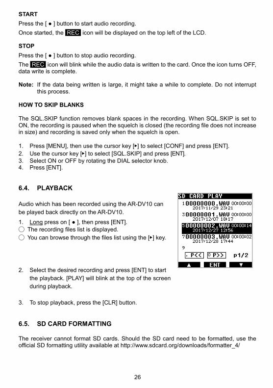
Audio which has been recorded using the AR-DV10 can
be played back directly on the AR-DV10.
1. Long press on [ ], then press [ENT].
The recording files list is displayed.
You can browse through the files list using the [] key.
2. Select the desired recording and press [ENT] to start
the playback. [PLAY] will blink at the top of the screen
during playback.
3. To stop playback, press the [CLR] button.
6.5. SD CARD FORMATTING
The receiver cannot format SD cards. Should the SD card need to be formatted, use the official SD formatting utility available at http://www.sdcard.org/downloads/formatter_4/

27
7. MEMORY CHANNEL & SCAN OPERATIONS • AR-DV10 can store 2000 memory channels, divided into 40 banks of 50 memory chan-
nels each. • Frequencies can be conveniently stored into “memory channels”, along with the
Modulation Type, IF bandwidth, etc... • Frequently used groups of frequencies can be stored into “memory banks”, which can be
scanned either individually or in a group of linked banks. • The SCAN function continually searches through the memory channels registered into a
memory bank, then stops or pauses when an active channel is encountered. • Memory channels are numbered from 00 to 49. • Memory banks are numbered from 00 to 39. • Scan groups are numbered from 0 to 9. • It is crucial to correctly set the SQUELCH level for the scan function to operate. To set
the squelch, tune the receiver to an inactive frequency, then increase the squelch level just up to the point where the noise is muted. The squelch should open only when a signal is active on the frequency.
7.1. SAVE A FREQENCY INTO A MEMORY CHANNEL
Frequencies can be conveniently stored into “memory channels”, along with the Modulation Type, IF bandwidth, Scan PASS, Memory Protection status, and a Name Tag.
To save a frequency into memory (fast way):
1. Tune to the desired frequency and set the correct Modulation Type and IF bandwidth.
2. Long press [ENT] to access the memory channel registration page.
Line 1, [BANK-CH] will be highlighted. the next available memory bank and memory channel number will be se-lected to be assigned.
(If this is the first time a frequency is saved into a memory channel, it will be BANK 00, CHANNEL 00.)
If the correct MODE and IFBW are previously set, and you do not wish to assign a channel name at this point, continue and save the settings as follows:
3. Use the [] button to move to the last line [MEM CH PARAM SET] and press [ENT].
To save a frequency into a memory channel (with name tag and edit details):
Long press [ENT] to access the memory channel registration page.
To edit any of the parameters, use the [] button to highlight the parameter to be changed, press [ENT] to edit each one as follows:
BANK-CH: Use the keypad to enter the bank number and channel number, followed by
[ENT]. For example: [0110] + [ENT] for bank 01 and channel 10.

28
FREQ: Use the keypad to enter the frequency in MHz, followed by [ENT].
MODE: Rotate the dial selector knob to select the desired modulation type, and press [ENT].
IFBW: Rotate the dial selector knob to select the desired IF bandwidth, and press [ENT].
PASS: Rotate the dial selector knob to toggle Frequency Pass ON or OFF, then press [ENT]. When set to ON, this memory channel will be ignored when the memory bank is scanned.
T: Input a nametag as described in chapter 10.3 “INPUT CHARACTERS & SYMBOLS”.
PROTECT: Rotate the dial selector knob to toggle the protect ON or OFF, then press [ENT].When set to ON, this memory channel cannot be erased. (Refer to page 2/2)
SQL N/L: Rotate the dial selector knob to choose from LEVEL, NOISE or AUTO squelch.
SQL TYPE: Rotate the dial selector knob to choose from CTCSS, DCS, Reverse Tone and OFF.
CTCSS: Rotate the dial selector knob to set the CTCSS tone frequency manually, or in automatic discovery mode (SRCH), or OFF.
DCS CODE: Rotate the dial selector knob to set the DCS tone code manually, or in automatic discovery mode (SRCH), or OFF.
AGC: Rotate the dial selector knob to set automatic gain control to FAST, MID, SLOW or RF-G.
OFFSET F.: Set the offset frequency function as described in chapter 10.8 “OFFSET RECEPTION”.
V.SCR: Set the voice descrambler function as described in chapter 10.6 “ANALOG VOICE DESCRAMBLER”
Finally save all of the settings: Use the [] button to go to the line 9, [MEM CH PARAM SET] and press [ENT].
7.2. SCAN A MEMORY BANK The scan mode searches the memory channels that have previously been registered in one or more memory banks, for active signals. It is crucial to correctly set the SQUELCH level for the scan function to operate. To set the squelch, tune the receiver to an inactive frequency, then increase the squelch level just up to the point where the noise is muted. The squelch should open only when a signal is active on the frequency.
[SCN] Scan mode
Memory bank number and memory channel number
Memory bank title Memory channel title

29
To scan a memory bank:
1. Go to [MENU], use the [] button to select [SCAN] and press [ENT].
2. Use the [] button to select [BANK] and press [ENT]. 3. Enter the number of the bank to be scanned using the keypad. Scan will start
immediately. • If scan stops on an inactive frequency, it means that the squelch level needs to be
increased, as follows: Press the SQL/MONI switch and turn the dial selector knob clockwise until the noise mutes and scan resumes. Press SQL/MONI again to save the squelch value.
• Scan direction can be changed with the [] and [] keys.
• To force scan to resume (even though it stopped on an active frequency), turn the dial selector knob by one increment, clockwise or counter-clockwise, depending on the scan direction.
• If the modulation type is changed while scan is stopped on an active frequency, the new mode will be saved into that memory channel.
To copy a scanned channel to VFO:
• When scan has stopped on an active frequency of interest, this frequency channel,
along with all its VFO settings, can be copied to and received on VFO-Z.
•
•
•
•
•
•
•
•
To switch to memory channel browser during scan:
• When scan has stopped on an active frequency of interest, you can temporarily
switch to memory channel browser mode.
Press [ENT] to copy
to VFO-Z
Press [ENT] to return
to scan
Press [MENU], go to [SCAN]
and press [ENT].
Press [MENU], go to [MEM]
and press [ENT].

30
7.3. SCAN PASS
The scan pass function may be marked as a memory channel to be ignored during scan. This is useful to temporarily disable memory channels, without having to erase them. For example, while scanning a memory bank, if scan has stopped on an active signal, but you want to bypass this frequency for future scans. While scan is stopped on that frequency (memory channel), proceed as follows: Press [MENU] followed by [ENT]. Use the [] button to select [PASS ON] and press [ENT]. To reintegrate a frequency into the scans, use the properties menu (See chapter 7.5 “EDIT A MEMORY CHANNEL”).
7.4. BROWSE MEMORY BANKS/CHANNELS Memory channels already programmed with saved frequencies can be manually browsed and received as follows: Press [MENU], use the [] button to go to [MEM] and press [ENT] twice. There are 2 ways to browse through memory channels:
• Rotating the dial selector knob. Each increment tunes to the next registered memory channel.
• Use the keypad for direct input of the bank and channel numbers, just enter the desired bank number followed by [ENT]. tuning will start with the lowest registered memory channel in that bank.
[MEM] Memory channel browser mode
Memory band and memory channel numbers
Memory bank title Memory channel title

31
7.5. EDIT A MEMORY CHANNEL A memory channel which already contains a saved frequency, can be edited as follows:
1. Press [MENU] and use the [] button to move to [MEM] and press [ENT]
2. Use the [] button to move to [CH EDIT] and press [ENT] twice.
3. Use the keypad to enter the bank number and channel number, followed by [ENT].
For example: [0110] + [ENT] for bank 01 and channel 10.
4. To edit any of the parameters, just use the [] button to highlight the parameter to be changed, then press [ENT] to edit each one as follows:
BANK-CH: Use the keypad to enter the bank number and channel number, followed by [ENT].
Example: [0110] + [ENT] for bank 01 and channel 10.
FREQ: Use the keypad to enter the frequency in MHz, followed by [ENT].
MODE: Rotate the dial selector knob to select the desired modulation type, then press [ENT].
IFBW: Rotate the dial selector knob to select the desired IF bandwidth, then press [ENT].
PASS: Rotate the dial selector knob to toggle the frequency PASS, ON or OFF, then press [ENT]. If set to ON, this memory channel will be ignored when the memory bank is scanned.
T: Input a name as described in chapter 10.3 “INPUT CHARACTERS & SYMBOLS”.
PROTECT: Rotate the dial selector knob to toggle PROTECT, ON or OFF, then press [ENT]. If set to ON, this memory channel cannot be erased (refer to page 2/2).
SQL N/L: Rotate the dial selector knob to choose from LEVEL, NOISE or AUTO squelch.
SQL TYPE: Rotate the dial selector knob to choose from CTCSS, DCS, Reverse Tone and OFF.
CTCSS: Rotate the dial selector knob to set the CTCSS tone frequency to Manual, Automatic Discovery Mode (SRCH), or OFF.
DCS CODE: Rotate the dial selector knob to set the DCS tone code to Manual, Automatic Discovery Mode (SRCH), or OFF.
AGC: Rotate the dial selector knob to set automatic gain control to FAST, MID, SLOW or RF-G.
OFFSET F.: Set the offset frequency function as described in chapter 10.8 “OFFSET RECEPTION”.

32
V.SCR: Set the voice descrambler function as described in chapter 10.6 “ANALOG VOICE DESCRAMBLER”.
5. Finally save all the settings: Use the [] button to go to the line 9, [MEM CH PARAM SET] and press [ENT].
7.6. ASSIGN TITLES TO MEMORY BANKS A title may be assigned to each memory bank, and PROTECTON set, so the bank is not accidentally erased. 1. Press [MENU], use the [] button to select [MEM] and then press [ENT].
2. Use the [] button to select [BANK EDIT] and then press [ENT].
3. To edit any of the parameters, just use the [] button to highlight the parameter to be changed, then press [ENT] to edit as follows:
T: Input a bank title as described in chapter 10.3 “INPUT CHARACTERS & SYMBOLS”.
PROTECT: Rotate the dial selector knob to toggle PROTECT, ON or OFF, then press [ENT]. If set to ON, this memory bank cannot be erased.
4. Finally save all of the settings: Use the [] button to move to line 9, [MEM CH PARAM
SET] and press [ENT]. 7.7. CREATE A GROUP OF LINKED MEMORY BANKS There are 10 scan groups (numbered 0 to 9) that may be set up individually to scan a group of linked memory banks. Each scan group can be setup with its own squelch behavior as follows:
Delay time, is the pause after the signal drops until the squelch closes and scan
resumes. Free time, is the time after which scanning will resume, whether or not the signal is
interrupted.

33
Create a scan group:
1. Press [MENU], use the [] button to select [SCAN], then press [ENT].
2. Use the [] button to select [GRP EDIT], then press [ENT] twice. 3. Enter the scan group number to be created, with the keypad.
This illustration shows an example of scan group 0 and all bank numbers from 00 to 39 which can be linked, providing they already have frequencies registered.
4. Press the [] button followed by [ENT], that will select the first bank 00 (the selected bank will blink).
For Example: to link banks 00 and 01:
5. Press the [.] key to register bank 00. 6. Use the [] button to move to bank 01 then press the [.]
key to register bank 01. (You can also rotate the dial selector knob to rapidly scroll through the bank num-bers)
If another bank number is selected by mistake, it may be deselected with the [.] key.
The linked banks 00 and 01 will appear as follows:
00 01 02 03 04 05 06 07 08 09
10 11 12 13 14 15 16 17 18 19
20 21 22 23 24 25 26 27 28 29
30 31 32 33 34 35 36 37 38 39
7. Press the [9] key to save the bank link selection and move to the following settings for
[DELAY TIME].
Delay time:
Is the time after the signal drops until the squelch closes, and scan resumes. Delay time can be set between 0.1 and 10 seconds, in 0.1 second increments. [OFF] is no delay. Default is 2 seconds. Press [ENT] and rotate the dial knob to select the desired timing. Press [ENT] to Validate the setting. The following setting [FREE] is now selected.
Free time: Free time, is the time after which scanning will resume, whether or not the signal is interrupted. Free time can be set between 1 and 60 seconds. [OFF] means scanning will resume only after the signal drops, as set in “Delay time”. Default is [OFF].
8. Press [ENT] and rotate the dial knob to select the desired timing. 9. Press [ENT] to validate the setting. 10. Press [ENT] to save all the settings of this group link page.

34
7.8. SCAN A GROUP OF LINKED MEMORY BANKS
Select the scan group of linked memory banks to be scanned:
1. Press [MENU], use the [] button to select [SCAN], then press [ENT].
2. Use the [] button to select [GRP], then press [ENT]. 3. Input the scan group number with the keypad, then
press [ENT].
Start scanning this group:
1. Press [MENU], then use the [] button to select [SCAN] and, then press [ENT].
2. Press [ENT] again.
7.9. COPY/ERASE/MOVE CHANNELS, BANKS AND GROUPS
Copy, move, and erase the contents of memory channels, memory banks and scan groups
as follows:
1. Press [MENU].
2. Use [] to select [EDIT], then press [ENT].
3. Use [] to select the data COPY, MOVE or ERASE
category.
MEM CH: For just a single memory channel.
MEM BANK: For an entire memory bank.
SCAN GRP: For a scan group.
4. Press [ENT] and rotate the dial selector to chose either:
COPY: To copy data
MOVE: To move data (the original will be lost)
DEL: To delete data
5. Press [ENT] to save the data input screen.
6. Using the dial knob, select the data to be erased, copied
or to be moved to the target location, and then move to
the next selection with the [] key.
7. When all the data is entered, initiate the copy, move, or
erase procedure by selecting: [XXX EXEC] and then
press [ENT].
「WRITING MEMORY...」will be displayed for a short time until the procedure is
completed.

35
8. PRIORITY RECEPTION
• The PRIORITY feature permits checking for activity on one of the 2000 memory
channels, while the AR-DV10 continues scanning, searching or monitoring. The receiver
is momentarily tuned to the priority channel frequency to listen for any signal. If activity is
found, the AR-DV10 will remain on the active frequency until the signal disappears. If no
activity is detected, the receiver returns to the original VFO frequency, scan channel or
search bank.
• The priority function has a large number of applications and is particularly useful for
monitoring a distress frequency while scanning or searching another frequency band.
• Note: Depending upon the frequency and mode stored as the priority channel, an
audible click may be heard when the priority function is in operation. This is quite normal
and is caused by the internal switching of circuitry necessary to accomplish the
frequency change (as two frequencies cannot simultaneously be monitored).
• The priority mode is automatically suspended while entering frequencies via the numeric
keypad, this prevents changing frequency while programming the AR-DV10.
How to setup the priority channel:
1. Press [MENU], use the [] key to select [MEM], then
press [ENT].
2. Use the [] key to select [PRIO] and press [ENT].
3. Press [ENT] and turn the dial knob to toggle the
priority function ON or OFF.
4. Use the [] key to select [BANK-CH] and press [ENT].
5. Enter the priority channel bank number and channel
number in the xx-yy format.
6. Press [ENT] and rotate the dial knob to set the interval
time in seconds, between 1 and 99 seconds.
7. Press [ENT] to start this function.

36
9. PROGRAM SEARCH
• This function tunes the receiver through all frequencies between two specified frequency limits in the predetermined step size, looking for active frequencies.
• The search instructions may be programmed into “search banks”. • There are 40 search banks, numbered from 00 to 39. • Search banks can be searched either individually or in a group of linked banks. • There are 10 search groups, numbered from 00 to 09. • It is crucial to correctly set the SQUELCH level for the search function to operate. To set
the squelch, tune the receiver to an inactive frequency, then increase the squelch level just up to the point where the noise is muted. The squelch should open only when a signal is active on the frequency.
Note: Search mode is extremely effective for AM & NFM use in the VHF and UHF bands.
Searching the shortwave bands is usually ineffective due to the relatively high background noise.
9.1. CREATE A SEARCH BANK The band frequency limits, the modulation type, the search bank title, etc... may be registered using the search bank edit menu.
1. Press [MENU], use the [] button to move to [SRCH], then press [ENT].
2. Use the [] button to move to [BANK EDIT], then press [ENT] to access the bank edit menu.
3. To edit any of the parameters, just use the [] button to highlight the parameter to be changed, then press [ENT] to edit as follows:
BANK: Use the keypad to enter the two-digit search bank number.
LOW F.: Use the keypad to enter the lower frequency limit in MHz, then press [ENT].
HI F.: Use the keypad to enter the higher frequency limit in MHz, then press [ENT].
MODE: Rotate the dial knob to select the desired modulation type, and then press [ENT].
IFBW: Rotate the dial knob to select the desired IF bandwidth, and then press [ENT].
STEP: Rotate the dial knob to select the desired step size between 10Hz and 500kHz, then press [ENT].
T: Input a search bank title as described in chapter 10.3 “INPUT CHARACTERS & SYMBOLS”.

37
PROTECT: Rotate the dial knob to toggle protect ON or OFF, and press [ENT].
When set to ON, this search bank cannot be erased. (refer to page 2/2)
SQL N/L: Rotate the dial knob to choose between LEVEL, NOISE or AUTO squelch.
SQL TYPE: Rotate the dial knob to choose between CTCSS, DCS, reverse tone and OFF.
CTCSS: Rotate the dial knob to set the CTCSS tone frequency manually, or to automatic discovery mode (SRCH), or OFF.
DCS CODE: Rotate the dial knob to set the DCS tone code manually, to automatic discovery mode (SRCH), or to OFF.
AGC: Rotate the dial knob to set automatic gain control to FAST, MID, SLOW or RF-G.
OFFSET F.: Set the offset frequency function as described in chapter 10.8 “OFFSET RECEPTION”.
V.SCR: Set the voice descrambler function as described in chapter 10.6 “ANALOG VOICE DESCRAMBLER”.
Finally, to save all the settings: Use the [] button to move to line 9 [MEM CH PARAM SET]
and then press [ENT].
9.2. RUN A SEARCH
The receiver search mode scans the step frequencies between the two frequency limits that have been set previously, looking for active frequencies. It is crucial to correctly set the SQUELCH level for the scan function to operate. To set the squelch, tune the receiver to an inactive frequency, then increase the squelch level just up to the point where the noise is muted. The squelch should open only when a signal is active on the frequency.
To scan a search bank:
1. Go to [MENU], use the [] button to select [SRCH], then press [ENT].
2. Use the [] button to select [BANK] and then press [ENT].
3. Using the keypad, enter the bank number to be searched. Search will start immediately. • If scanning stops on an inactive frequency, the squelch level may need to be
increased, as follows: Press the SQL/MONI switch and turn the dial knob clockwise until the noise mutes
and scanning resumes. Press SQL/MONI again to save that squelch value. • The search direction may be changed by pressing the [] or [] keys.
• To force search to resume when scanning has stopped on an active frequency, turn the dial knob by one increment, clockwise or counter-clockwise.
SER Search mode
Search bank number
Search bank title

38
To copy a search channel to VFO:
• When search has stopped on an active frequency of interest, this frequency channel,
along with all its VFO settings, can be copied to receiver VFO-Z.
9.3. SEARCH PASS This function allows individual frequencies to be skipped when during scanning. This can be useful to remove blank carriers or unwanted signals from continually stopping the scan process. Each of the 40 search banks can store up to 50 pass frequencies, for a total of 2000 skipped frequencies. How to register a pass frequency: While search is stopped on an unwanted frequency, proceed as follows: Press [MENU] followed by [ENT]. Use the [] button to select [PASS ON] and press [ENT]. How to erase a pass frequency: See chapter 9.6 “COPY/ERASE/MOVE SEARCH BANKS, GROUPS AND PASS FREQ.”
Press [ENT] to return
to search
Press [ENT] to copy
to VFO-Z
39
9.4. CREATE A GROUP OF LINKED SEARCH BANKS There are 10 search groups (numbered 0 to 9) that may be set up individually to search a group of linked search banks. Each search group can be setup with its own squelch parameters as follows:
Delay time: Time between the signal dropout and squelch closing, for search to resume. Free time: The time after which scanning will resume, whether or not the signal drops
out. Auto store: The first 50 active frequencies located during scanning are automatically
saved in memory bank 39, for later review and scanning.
How to create a search group:
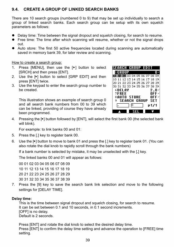
1. Press [MENU], then use the [ ] button to select
[SRCH] and then press [ENT]. 2. Use the [] button to select [GRP EDIT] and then
press [ENT] twice. 3. Use the keypad to enter the search group number to
be created.
This illustration shows an example of search group 0 and all search bank numbers from 00 to 39 which can be linked, providing of course they have already been programmed.
4. Pressing the [] button followed by [ENT], will select the first bank 00 (the selected bank will blink).
For example: to link banks 00 and 01:
5. Press the [.] key to register bank 00.
6. Use the [] button to move to bank 01 and press the [.] key to register bank 01. (You can
also rotate the dial knob to rapidly scroll through the bank numbers)
If a bank number is selected by mistake, it may be unselected with the [.] key.
The linked banks 00 and 01 will appear as follows:
00 01 02 03 04 05 06 07 08 09
10 11 12 13 14 15 16 17 18 19
20 21 22 23 24 25 26 27 28 29
30 31 32 33 34 35 36 37 38 39
7. Press the [9] key to save the search bank link selection and move to the following
settings for [DELAY TIME].
Delay time:
This is the time between signal dropout and squelch closing, for search to resume. It can be set between 0.1 and 10 seconds, in 0.1 second increments. [OFF] is no delay. Default is 2 seconds. Press [ENT] and rotate the dial knob to select the desired delay time. Press [ENT] to confirm the delay time setting and advance the operation to [FREE] time setting.

40
Free time:
This is the time after which scanning will resume, whether or not the signal drops out. Free time can be set between 1 and 60 seconds. [OFF] means search will only resume after the signal drops, as set in “Delay time”. Default is [OFF].
8. Press [ENT] and rotate the dial knob to select the desired timing. 9. Press [ENT] to save the setting. Auto store:
The first 50 busy frequencies located during search are automatically saved in memory bank 39, for later review and scanning.
10. Press [ENT] and rotate the dial selector knob to set auto store ON or OFF (default). 11. Press [ENT] to save the setting. 12. Press [ENT] again, to save all of this group link page setting.
9.5. SEARCH A GROUP OF LINKED SEARCH BANKS
Select the search group of previously linked search banks: 1. Press [MENU] use the [] button to select [SRCH] and
then press [ENT]. 2. Use the [] button to select [GRP], then press [ENT]. 3. Input the search group number with the keypad.
To start scanning this group: 4. Press [MENU], then use the [] button to select [SRCH]
and press [ENT]. 5. Press [ENT] again.
9.6. COPY/ERASE/MOVE SEARCH BANKS, GROUPS AND PASS FREQ.
Follow this procedure to copy, move, and erase the contents of search banks and search
groups, also pass frequencies may be deleted.
1. Press [MENU]. 2. Use [] to select [EDIT], then press [ENT].
41
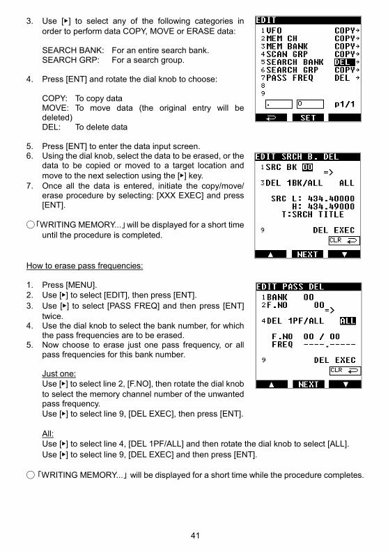
3. Use [] to select any of the following categories in order to perform data COPY, MOVE or ERASE data:
SEARCH BANK: For an entire search bank. SEARCH GRP: For a search group.
4. Press [ENT] and rotate the dial knob to choose:
COPY: To copy data MOVE: To move data (the original entry will be deleted) DEL: To delete data
5. Press [ENT] to enter the data input screen. 6. Using the dial knob, select the data to be erased, or the
data to be copied or moved to a target location and move to the next selection using the [] key.
7. Once all the data is entered, initiate the copy/move/ erase procedure by selecting: [XXX EXEC] and press [ENT].
「WRITING MEMORY...」will be displayed for a short time
until the procedure is completed.
How to erase pass frequencies: 1. Press [MENU]. 2. Use [] to select [EDIT], then press [ENT].
3. Use [] to select [PASS FREQ] and then press [ENT]
twice. 4. Use the dial knob to select the bank number, for which
the pass frequencies are to be erased. 5. Now choose to erase just one pass frequency, or all
pass frequencies for this bank number. Just one: Use [] to select line 2, [F.NO], then rotate the dial knob
to select the memory channel number of the unwanted pass frequency.
Use [] to select line 9, [DEL EXEC], then press [ENT]. All: Use [] to select line 4, [DEL 1PF/ALL] and then rotate the dial knob to select [ALL].
Use [] to select line 9, [DEL EXEC] and then press [ENT]. 「WRITING MEMORY...」will be displayed for a short time while the procedure completes.

42
10. ADVANCED OPERATION 10.1. SIGNAL ATTENUATOR
This function is used to lower the receiver sensitivity in case the signal is too strong (audio is
distorted), thus overloading the receiver RF stage.
The attenuation is approx. 10dB. However the S-meter value remains unchanged.
1. Press [MENU] then use [] to select [OPT] and press [ENT].
2. Use [] to select line 2, [ATT] and press [ENT].
3. Select ON or OFF with the dial knob. 4. Press [ENT] four times.
When set to ON, [ATT] will be displayed on the main screen.
10.2. AGC
AGC (automatic gain control) balances the average volume despite amplitude variations in the input signal. The recovery time of AGC can be adjusted for AM signals (AM, USB, LSB, CW) to better fit specific kinds of signals.
Typically, FAST is used for CW (Morse code signals), SLOW for USB and LSB, and MID for AM broadcasts.
1. Press [MENU], then [ENT]. 2. Use [] to select [VFO EDIT], then press [ENT].
3. Use [] to select line 9, [AGC], then press [ENT].
4. Select the desired recovery time with the dial knob.
Available selections are: FAST: AGC with fast recovery timing MID: AGC with average recovery timing SLOW: AGC with slow recovery timing RF-G: Manual gain
5. Use [] to select line 9, [VFO PARAM SET], then press [ENT] to save the selection.

43
When manual gain RF-G is selected, then set the gain level as follows: 1. Press [MENU], then press [ENT]. 2. Use [] to select [CONF], then press [ENT]
3. Use [] to select [RF-GAIN], then press [ENT] 4. Select the desired gain level (between 000 and 255) with
the dial knob. Manual gain is particularly effective for CW, LSB and USB signals where careful adjustment often provides a reduction of background noise.
10.3. INPUT CHARACTERS & SYMBOLS The following alphanumeric characters and symbols can be used to name memory channels, memory banks and search banks. Characters and symbols available for each numerical key
1 ABC A B C a b c 1
2 DEF D E F d e f 2
3 GHI G H I g h i 3
4 JKL J K L j k l 4
5 MNO M N O m n o5
6 PQRS
P Q R S p q r s 6
7 TUV T U V t u v 7
8 WXYZ
W X Y Z w x y z 8
9 +-*/ + - * / 9
. (reverse character cycle)
0 [ ] _ | , .
[ ] _ | , . (blank space insert) 0
• Use the arrows [] or [] to position the cursor where a character is to be input.
• Click the numerical key corresponding to the character or symbol of choice. Press that key until the needed character is displayed.
• Press [] to move to the next position.
• To erase the currently selected character, press [CLR].
• To insert a new character between two existing characters, place the cursor on the second character and input the new character.
• To save the entries, press [ENT].
S P

44
An alternative method to select characters and symbols is by rotating the dial knob. This method gives a wider choice of symbols than the key entry.
10.4. DATA EDITOR (COPY, MOVE, DELETE)
The contents of memory channels, memory banks, scan groups, search banks, and search
groups may be copied, moved, and erased.
1. Press [MENU].
2. Use [] to select [EDIT], then press [ENT].
3. Use [] to select any of the following categories and then
COPY, MOVE or ERASE the data:
MEM CH: For just a single memory channel.
MEM BANK: For an entire memory bank.
SCAN GRP: For a scan group.
SEARCH BANK: For a search bank.
SEARCH GRP: For a search group
4. Press [ENT] and rotate the dial selector to choose either:
COPY: To copy data
MOVE: To move data (the original will be lost)
DEL: To delete data
5. Press [ENT] to access the data input screen.
6. Using the dial knob, select the data to be erased, or the
data to be copied or moved to a target location, then
move to the next selection with the [] key.
7. Once all the data is entered, initiate the copy/move/erase
procedure by selecting: [XXX EXEC] and then press
[ENT].
「WRITING MEMORY...」will be displayed for a short time, until the procedure is
completed.
ABCDEFGHIJKLMNOPQRSTUVWXYZ[\]^_`
abcdefghijklmnopqrstuvwxyz|~ (blank space) !”#$%&’()*+,-./0123456789:;<=>?@
45
10.5. ADVANCED SQUELCH TYPES
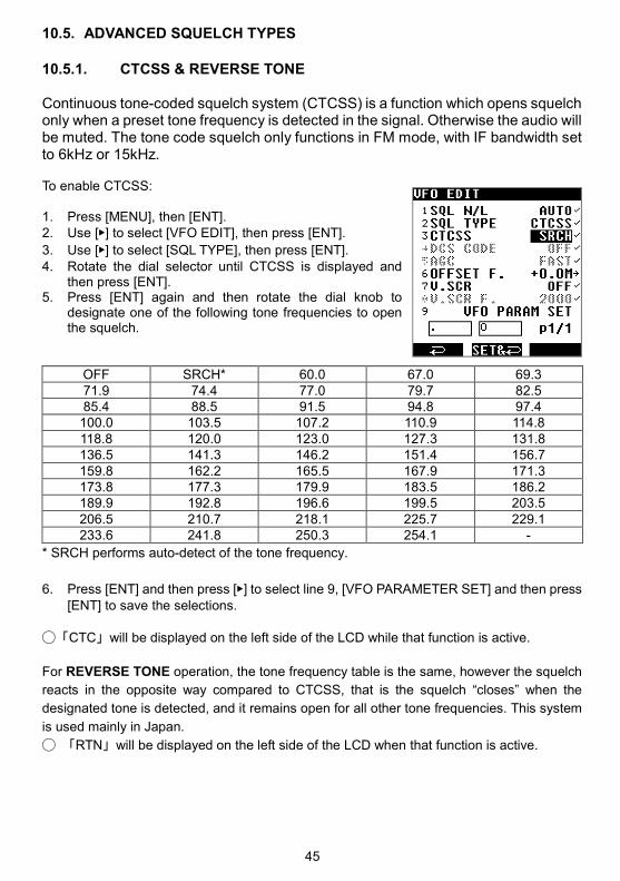
10.5.1. CTCSS & REVERSE TONE Continuous tone-coded squelch system (CTCSS) is a function which opens squelch only when a preset tone frequency is detected in the signal. Otherwise the audio will be muted. The tone code squelch only functions in FM mode, with IF bandwidth set to 6kHz or 15kHz. To enable CTCSS: 1. Press [MENU], then [ENT]. 2. Use [] to select [VFO EDIT], then press [ENT].
3. Use [] to select [SQL TYPE], then press [ENT]. 4. Rotate the dial selector until CTCSS is displayed and
then press [ENT]. 5. Press [ENT] again and then rotate the dial knob to
designate one of the following tone frequencies to open the squelch.
OFF SRCH* 60.0 67.0 69.3 71.9 74.4 77.0 79.7 82.5 85.4 88.5 91.5 94.8 97.4
100.0 103.5 107.2 110.9 114.8 118.8 120.0 123.0 127.3 131.8 136.5 141.3 146.2 151.4 156.7 159.8 162.2 165.5 167.9 171.3 173.8 177.3 179.9 183.5 186.2 189.9 192.8 196.6 199.5 203.5 206.5 210.7 218.1 225.7 229.1 233.6 241.8 250.3 254.1 -
* SRCH performs auto-detect of the tone frequency.
6. Press [ENT] and then press [] to select line 9, [VFO PARAMETER SET] and then press [ENT] to save the selections.
「CTC」will be displayed on the left side of the LCD while that function is active.
For REVERSE TONE operation, the tone frequency table is the same, however the squelch
reacts in the opposite way compared to CTCSS, that is the squelch “closes” when the
designated tone is detected, and it remains open for all other tone frequencies. This system
is used mainly in Japan.
「RTN」will be displayed on the left side of the LCD when that function is active.
46
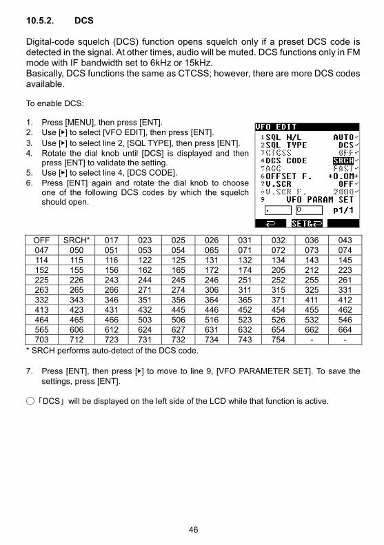
10.5.2. DCS
Digital-code squelch (DCS) function opens squelch only if a preset DCS code is detected in the signal. At other times, audio will be muted. DCS functions only in FM mode with IF bandwidth set to 6kHz or 15kHz. Basically, DCS functions the same as CTCSS; however, there are more DCS codes available. To enable DCS: 1. Press [MENU], then press [ENT]. 2. Use [] to select [VFO EDIT], then press [ENT].
3. Use [] to select line 2, [SQL TYPE], then press [ENT]. 4. Rotate the dial knob until [DCS] is displayed and then
press [ENT] to validate the setting. 5. Use [] to select line 4, [DCS CODE].
6. Press [ENT] again and rotate the dial knob to choose one of the following DCS codes by which the squelch should open.
OFF SRCH* 017 023 025 026 031 032 036 043 047 050 051 053 054 065 071 072 073 074 114 115 116 122 125 131 132 134 143 145 152 155 156 162 165 172 174 205 212 223 225 226 243 244 245 246 251 252 255 261 263 265 266 271 274 306 311 315 325 331 332 343 346 351 356 364 365 371 411 412 413 423 431 432 445 446 452 454 455 462 464 465 466 503 506 516 523 526 532 546 565 606 612 624 627 631 632 654 662 664 703 712 723 731 732 734 743 754 - -
* SRCH performs auto-detect of the DCS code.
7. Press [ENT], then press [] to move to line 9, [VFO PARAMETER SET]. To save the
settings, press [ENT].
「DCS」will be displayed on the left side of the LCD while that function is active.

47
10.6. ANALOG VOICE DESCRAMBLER Scrambled analog voice transmissions can be decoded with the V.SCR function. The scrambler is sometimes used in public service radio, automobile racing and cordless telephones. This function is limited to FM mode with IF bandwidth of 6kHz and 15kHz. (V.SCR is not available in the U.S consumer version) To enable V.SCR:
1. Press [MENU], then press [ENT]. 2. Use [] to select [VFO EDIT], then press [ENT].
3. Use [] to select line 7, [V.SCR] and press [ENT]. 4. Turn the dial know until [ON] appears, then press [ENT]. 5. Press [ENT] again, then turn the dial knob to select the
desired carrier frequency (between 2000 and 7000Hz). 6. Press [ENT] twice to save the settings.
10.7. ADVANCED DIGITAL MODE SETTINGS These are advanced settings for the digital modes.
1. Access Digital Mode Settings with a long press on [MODE], then use [] to select [DIG CONF].
2. Select the desired line 1 to 9, with the arrows [] or [], followed by [ENT].
3. Change values:
・ For line 1, DCR ENC C, input the code directly with the keypad, then press [ENT] to validate the setting.
・ For lines with a check mark [], change the setting with the DIAL KNOB and press [ENT] to save it.
・ For line 6, P25 NAC C., choose a digit with the DIAL KNOB, then move to the next digit with [] and finally press [ENT] to save the setting.
4. Activate all of the previous settings by going to line 9, DIGI.CONF, and then press [ENT].
Details of the setting for each individual mode:
・(line 1) DCR ENC C. (15-bit digital scramble code setting, also for NXDN)
There are only 32767 possible combinations, between 00001 and 32767.
00000 no scramble code used.
Note: AR-DV10 also has an exclusive scramble code auto detect feature. While receiving a scrambled signal, press the key-lock key and “D-CR ENC.CODE” with a blinking “?” will appear on the bottom of the screen. It usually takes 2 or 3 seconds for the code to be found and for the audio to be descrambled.
This feature only works with NXDN/D-CR’s 15-bit digital scramble signals. A “scrambled” signal is not an “encrypted” signal. AR-DV10 cannot decode encrypted signals of any kind.

48
・(line 2) DMR slot selection Only the selected slots will be decoded. 1+2 Both slots but priority on SLOT1 2+1 Both slots but priority on SLOT2 1 SLOT1 only 2 SLOT2 only
・(line 3) DMR COLOR
When set to ON, the receiver will only decode signals corresponding to the color code number set in the (line 4) DMR COL C column. There are 16 possible color codes, from 01 to 16.
Code 00: all color codes are decoded.
・(line 5) P25 NAC
When set to ON, the receiver will only decode signals corresponding to the 3-digit hexadecimal NAC code set in (line 6) P25 NAC C.
Each digit can hold the value 0 to 9 or A to F. That makes 4096 possible NAC codes.
Code 000: all NAC codes are decoded.
・(line 7) NXDN RAN
When set to ON, the receiver will only decode signals corresponding to the RAN code number set in the (line 8) NXDN RAN C column. There are 63 possible color codes, from 01 to 63.
Code 00: all RAN codes are decoded.
DIGITAL SIGNAL INFO DISPLAY When using the D-STAR mode, by default the marked dotted area is used to display some user information. This information display can be toggled ON or OFF as follows: 1. Long press on [MODE]. 2. Use [] to select [DIGI DISP], then press [ENT].
3. Use [] to select either [DISP ON] or [DISP OFF],then press [ENT]

49
10.8. OFFSET RECEPTION AR-DV10 can be easily programmed to shift the receive frequency by a preprogrammed value. This is useful when receiving two-frequency radio communications, such as a base station and a mobile station or a relay station, that transmit to each other on two frequencies. The difference between the two frequencies is the offset frequency. Access the offset menu as follows: 1. Press [MENU] followed by [ENT]. 2. Use [] to select [VFO EDIT], then press [ENT].
3. Use [] to select either [OFFSET F.], then press [ENT]. 4. By rotating the dial knob, select a storage number be-
tween 00 and 39, depending on the following scenarios:
00: Offset is disabled 01〜19: Offset value to be configured manually
20〜39: Preset of common offset values 5. To enter a negative value, press the [0] key to toggle
[+] to [-]. 6. Press the [.] key to select the frequency input area. 7. Input the frequency in MHz, using the keypad numbers,
press [ENT] to validate the entry. 8. Use [] to select [VFO PARAM SET], then press [ENT]
to save the selection.
10.9. REMOTE MODE The receiver can be remotely controlled from a PC by using serial commands. The command list can be downloaded on our website. When the remote mode is active, on the VFO screen, the [] icon is displayed on the top left of the LCD. However. when the MENU-TOP screen is active the [] icon will be located on the top right of the LCD.
During remote control, all buttons and switches except the red power switch and [ENT] will be disabled. To deactivate remote control, press [ENT].

50
11. RECEIVER SETTINGS 11.1. CALENDAR & CLOCK
1. Press [MENU], then use [] to select [CLK] and then
press [ENT] 2. Using the number keys, input the date and time in the
following format: YY-MM-DD HH:MM For example: for 18-01-30 15:00 (Jan.30, 2018 at 15:00) just enter 1801301500, then press [ENT] to save the setting.
To change the time, proceed as follows: 1. Press [MENU], then use [] to select [CLK] and then press [ENT].
2. Press [], this will copy the actual date and time.
3. Press [] four times, followed by [ENT] to input the new time. Note:
There is no daylight-saving time feature. The system date and time will be input to the properties of the audio recording files. However, there is no date and time stamp in the recording file names.
11.2. SYSTEM SETTINGS There are two receiver configuration pages as shown below:
• Press [MENU] and use [] to select [CONFIG] to open the receiver settings menu.
• Select the desired line (1 to 9) with the [] key and then press [ENT] to move to the value
to be changed, at the right side of the screen. • Change the value by turning the dial knob. • Press [ENT] to validate and save the value.

51
1 BEEP (00-15) Beep volume level when a key is pressed, or to indicate an error. Default is 05.
2 VOL ATT (00-15)
Limits the maximum volume level. 00 is maximum volume, 15 is the most attenuated. For levels 06 and over, [VolATT] is displayed on screen. Default is 05.
3 CONTRAST (00-40)
Sets the LCD contrast level. Default is 30.
4 BACKLIGHT
Sets the LCD backlight behavior. OFF (default) Always OFF. Saves battery power. CONT Always ON. Consumes more battery. AUTO Switches ON when some keys or controls are operated, switches OFF automatically off after 5 seconds.
5 SQL.SKIP
Controls audio recording behavior. ON (default) Audio is only recorded when the squelch is open. OFF Audio is recorded whether the squelch is open or closed.
6 RES.CODE
Configuration of receiver control PC commands. ON (default) A result code is added to the beginning of a command response. OFF Command responses do not feature a result code.
7 PROTECT
Auto-store configuration when the receiver is switched OFF. ON Configuration auto-store is OFF. OFF (default) Configuration auto-store is ON.
8 RF-GAIN (000-255)
Manual gain control setting. Functions only when AGC is set to [RF-G] (Manual gain). This setting can be useful in SSB or CW to improve signal to noise ratio. Default is 000.
(p2/2 of MENU CONFIG) 4 SYSTEM RESET
All MENU settings are returned to factory default. Memory data is retained. 5 FULL RESET
All settings are returned to factory default and all memory data is deleted. 6 FACTORY MENU
Access is restricted to AOR Service Department. 7 FIRM
Displays the firmware version.

52
8 SER.
Displays the serial number of the receiver. 9 SYS.UPDATE
To apply a firmware update using the SD card. Download the latest firmware version at http://www.aorja.com/receivers/ar-dv10.html
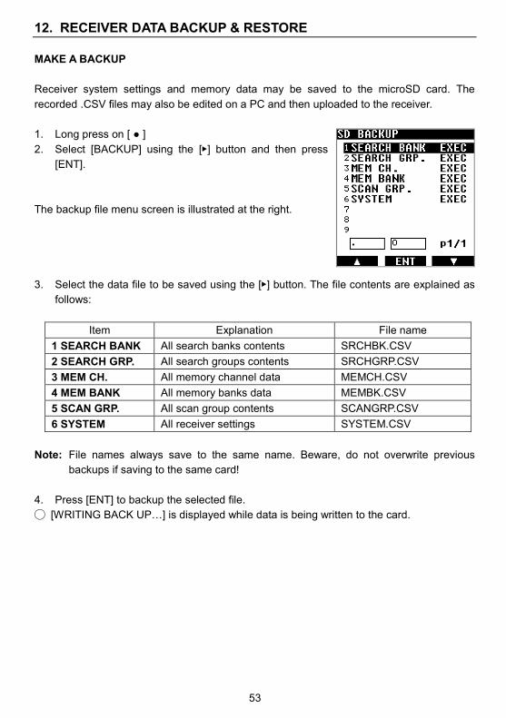
53
12. RECEIVER DATA BACKUP & RESTORE
MAKE A BACKUP
Receiver system settings and memory data may be saved to the microSD card. The
recorded .CSV files may also be edited on a PC and then uploaded to the receiver.
1. Long press on [ ]
2. Select [BACKUP] using the [] button and then press
[ENT].
The backup file menu screen is illustrated at the right.
3. Select the data file to be saved using the [] button. The file contents are explained as
follows:
Item Explanation File name
1 SEARCH BANK All search banks contents SRCHBK.CSV
2 SEARCH GRP. All search groups contents SRCHGRP.CSV
3 MEM CH. All memory channel data MEMCH.CSV
4 MEM BANK All memory banks data MEMBK.CSV
5 SCAN GRP. All scan group contents SCANGRP.CSV
6 SYSTEM All receiver settings SYSTEM.CSV
Note: File names always save to the same name. Beware, do not overwrite previous
backups if saving to the same card!
4. Press [ENT] to backup the selected file.
[WRITING BACK UPj] is displayed while data is being written to the card.

54
RESTORE A BACKUP
Backups saved on the SD card can be restored to the receiver. To facilitate the handling of
multiple backups, file names may be changed if desired, as long as they are up to 8 ASCII
characters. The receiver will recognize the kind of backup, no matter what file name is
assigned.
To restore a backup to the receiver, proceed as follows:
1. Long press on [ ] and press [ENT].
2. Select the desired backup file using the [] button.
3. Press [ENT] to restore the selected file to the receiver.
[WRITING MEMORY] is displayed while data is being
uploaded to the receiver.

55
13. FIRMWARE UPDATE
What is needed?
・ The supplied SD card containing the saved firmware file that may be downloaded at:
http://www.aorja.com/receivers/ar-dv10.html
If the receiver contains a large amount of scan and search data, it is advised to have at least 200MB free space on the card.
Words of caution!
・ The memory data and systems are very likely to be erased after a firmware update,
therefore it is always advised to first backup the receiver data as follows:
Press and hold the [] button
Press [2]
Press [6] (Note: “SYSTEM” means a complete backup)
・ Beware, the backup files will always be saved back to the same names, therefore
previous back-up files will be overwritten without warning. Please move previous
back-up files to your PC.
・ Do not cut the power or remove the SD card while the firmware is being uploaded to the
receiver! This could potentially corrupt system data and make the receiver unusable.
Such a happening would not be covered by the manufacturer warranty.
・ The firmware is the property of AOR Ltd. and should not be re-distributed, either in its
original form or in any modified form.
・ AOR will issue firmware updates to fix major bugs and add new functions, whenever
required by our development plan. However, there is no guarantee updates will be made
available at regular intervals.
Update procedure 1. The receiver must be OFF.
2. Lift the rubber cover labeled MicroSD.
3. Insert the SD card containing the update file (for example 1801C.D10) into the receiver slot. Refer to the illustration for the SD card’s orientation.
4. Switch the receiver ON.
Make sure there is enough battery power to complete the update. A power interruption
during the update procedure could potentially corrupt system data and make the
receiver unusable. Such a happening would not be covered by the manufacturer
warranty.
Wait until the boot procedure is complete and confirm that the SD card icon appears
on the right side of the LCD.
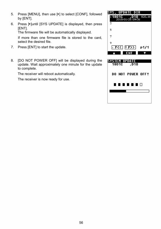
56
5. Press [MENU], then use [] to select [CONF], followed by [ENT].
6. Press []until [SYS UPDATE] is displayed, then press [ENT]. The firmware file will be automatically displayed.
If more than one firmware file is stored to the card, select the desired file.
7. Press [ENT] to start the update.
8. [DO NOT POWER OFF] will be displayed during the update. Wait approximately one minute for the update to complete.
The receiver will reboot automatically.
The receiver is now ready for use.

57
14. TROUBLESHOOTING
If the receiver appears to be defective, please check the following Q&A troubleshooting
assistance chart before contacting AOR. If the device cannot be operated properly after
reviewing the assistance information, kindly contact an AOR dealer for instructions.
Symptoms Possible causes What to do
Receiver does not
power on (no display)
・The lithium-ion battery
pack is discharged.
・The alkaline batteries
are depleted.
・The battery pack or the
alkaline battery tray is
not inserted correctly.
・The battery pack or the
alkaline battery tray
terminals are dirty.
・The connection of the
AC power adapter or
the cigarette lighter
DC/DC converter is
loose.
・Recharge the battery pack.
・Replace with new alkaline batter-
ies.
・Press the pack or the tray firmly
into place.
・Clean the terminals with a dry
cloth.
・Make sure that the plugs are in-
serted correctly.
No sound ・The squelch is set too
high.
・CTCSS and DCS are
active.
・A digital mode has been
selected.
・VOL ATT value is set
too high.
・Lower the squelch level.
・If CTC or DCS is displayed on
screen, disable these functions.
・That is normal, sound is only heard
when a digital signal is detected.
・Reduce the VOL ATT value.
Voice barely audible
(for analog reception)
Frequency slightly
offset
Try to fine-tune in 1kHz steps.
Signal is weak or affect-
ed by multi-path recep-
tion.
Try another location.
Voice is garbled
(for digital reception)
Incompatible digital
mode or encrypted sig-
nal received.
Sorry that is out of the scope of this
receiver.

58
D-STAR call sign is not
displayed.
Header of the transmis-
sion has not been re-
ceived. Especially dur-
ing SCAN and SEARCH,
hitting a signal in the
middle of a
transmission is likely.
・Wait for the next transmission
(header) to be received and de-
coded.
・If cause is unstable signal, try a
better location or larger antenna.
From, to, rep1, rep2
appears even though
it’s not a D-STAR
signal.
Noise was mistaken for
a digital signal.
This is not a malfunction. Try a new
location with better signal to noise
ratio, or a larger antenna.
Boot up is hanging,
does not boot normally
to VFO screen.
System data not loaded
correctly.
Remove all power sources, wait 1
minute, reinsert the battery pack
and power on again.
LCD display seems fro-
zen.
System data problem Reboot the receiver and do a sys-
tem reset.
59
15. SPECIFICATIONS
Frequency range 100kHz~1300MHz (Cellular frequencies blocked for US consumer version) Operation modes VFO, memory channel, program search, scan Analog receive modes WFM, NFM, AM, USB, LSB, CW Digital receive modes TETRA(Direct mode, mobile to mobile),DMR(Tier1/2/Mototrbo), NXDN(6.25k),
dPMR(446 Tier1), APCO25(Phase1), D-STAR, Yaesu(C4FM), Alinco(EJ47U), Japanese D-CR.
Circuit type 100kHz~1300MHz Single super heterodyne IF 47.25MHz SDR direct sampling WFM (64MHz~108MHz) SDR direct conversion
AM (520kHz~1710kHz) SDR direct conversion IF filter bandwidths Analog modes: 100kHz, 30kHz, 15kHz, 8kHz, 6kHz, 5.5kHz, 3.8kHz, 2.6kHz,
1.8kHz, 500Hz, 200Hz (choice is mode dependent) Digital modes: 6kHz, 15kHz, 30kHz (auto-select)
Assisted functions AGC, step-adjust, offset and priority receive. Analog voice descrambler (not available for US consumer version).
Signal attenuator Approx. 10dB ON/OFF Squelch modes Noise squelch, level squelch, reverse tone, digital voice detection. Frequency stability ±5ppm (+14°F to +122°F [-10°C to +50°C]) Sensitivity SSB (10dB S/N) 0.3µV (typical values) AM (10dB S/N) 1.6µV
FM (12dB SINAD) 0.3µV WFM (12dB SINAD) 2.6µV
Number of VFO’s 3 (A / B / Z) Memory channels 2000 Memory banks 40 Search banks 40 Priority channel 1 Pass frequencies 50 per bank or VFO Audio outputs Internal speaker min.700mW (@16Ω,10.5V,10%THD), earphones jack min. 200mW
(@8Ω,10.5V,10%THD) Antenna BNC 50Ω or earphone antenna for FM 64MHz -107.99999MHz. Max. antenna input 0dBm Power requirements 7.4V 2000mAh Lithium-ion battery pack (BP-10) External input 6.5V〜10.5V Current consumption 240mA(typ), 500mA(max) (excluding battery pack charge current) Case size 2.56” (W) x 5.40” (H) x 1.61” (D) (65 x 137 x 41mm)
(Including battery pack, excluding projections) Weight Approx. 14.8 oz (420g) (including battery pack, antenna and belt clip) Temperature range 14°F to +122°F (-10°C to +50°C) Supplied accessories AC power adapter, lithium-ion battery pack, fast charger cradle, belt clip,
antenna, cigarette lighter DC/DC converter, alkaline battery tray, microSD card, operating manual.
Specifications are subject to change without notice or obligation. Other company and product names
mentioned are the property of their respective owners. Product and brand names used are for
identification purposes only.
As per FCC rules, the US consumer version has cellular frequencies blocked and analog voice
descrambler function deactivated by hardware. These restrictions are final and cannot be reversed by
firmware change nor command input.

60
Digital voice mode compatibility chart:
• For a worldwide directory of D-STAR repeater frequencies (classified by country and
city), you may want to check the very informative D-Star Repeater Directory site at:
http://dstarusers.org/repeaters.php
• All stated features and specifications may by subject to change without notice nor
obligation. Other company and product names mentioned in this document are the
property of their respective owners. Product and brand names used are for
identification purposes only .
DIGITAL
MODE
IF
BANDWIDTHMODE ENCRYPTED / TRUNKED MODULATION
COMPATIBLE
VOCODER
AR-DV10
VOICE
DECODING
D-STAR 12.5kHz DV GMSK AMBE O
ALINCO 12.5kHz EJ-47 (VOICE F1E) GMSK AMBE O
V/D O
VOICE FR X
NON-ENCRYPTED O
DIGITAL SCRAMBLING O
NON-ENCRYPTED O
DIGITAL SCRAMBLING (15 BIT) O
ENCRYPTED & TRUNKED X
12.5kHz X
DPMR446 O
TIER 1 O
TIER 2 & 3 ENCRYPTED & TRUNKED X
NON-ENCRYPTED O
ENCRYPTED X
NON-ENCRYPTED & TRUNKED X
ENCRYPTED & TRUNKED X
NON-ENCRYPTED O
ENCRYPTED X
TIER 3 ENCRYPTED & TRUNKED X
DIRECT MODE NON-ENCRYPTED O
REPEATER & BASE ENCRYPTED & TRUNKED X
6.25kHz
NXDN6.25kHz
AMBE+2
YAESU
D-CR
12.5kHz AMBE+2
AMBE+26.25kHz
REGULAR MODE
C4FM
C4FM
C4FM
TIER 1 & 2
IMBE
12.5kHz AMBE+2PHASE 2
AMBE+2
DMR /
MOTOTRBO12.5kHz AMBE+2
TETRA 25 kHzTETRA
COODEC
P25
DPMR C4FM
C4FM
H-CPM/ H-DQPSK
C4FM
π/4 shift QPSK
6.25kHz &
12.5kHzPHASE 1

61
®
Declaration of Conformity We, AOR Ltd. certify and declare under our sole responsibility that the following equipment
complies with the essential requirements of the Directive 89/336/EWG changed by
2004/108/EWG v.19.04.2016; 19.04.2016; 2014/30/EU and low voltage Directive
2006/95/EG.
Type of Equipment: DIGITAL RECEIVER
Brand Name: AOR
Model Number: AR-DV10
Manufacturer: AOR Ltd.
Address of Manufacturer: 2-6-4, MISUJI, TAITO-KU 111-0055, JAPAN
Applicable Standards:
This equipment is tested and conforms to the essential requirements of Directive, as
included in following standards.
EN 55032:2015 Class B /Emission
EN 60 950-1 Safety
EN 61000-4-3 Radiated RF Immunity
EN 61000-4-2 Electrostatic discharge
The technical documentation as required by the Conformity Assessment procedures is kept
at the following address:
Company: AOR Ltd.
Address: 2-6-4, MISUJI, TAITO-KU 111-0055, JAPAN
Telephone: +81-3-3865-1695
E-mail: [email protected]

62
® AOR, LTD.
2-6-4, Misuji, Taito-Ku,
Tokyo, 111-0055, Japan
URL: www.aorja.com
Authority On Radio Communications No portion of this manual may be reproduced in English or any other language without the permission of AOR, LTD.
©2018 AOR, LTD. All rights reserved. E.U/US(U) v.2018-04-18