digital circuits synchronization guideline circuits... · web viewthis guideline outlines...
TRANSCRIPT

WECC Guideline
Digital Circuits SynchronizationMarch 8, 2018
155 North 400 West, Suite 200
Salt Lake City, Utah 84103-1114
WECC Guideline: Digital Circuits Synchronization 2
Table of Contents
I. Introduction...............................................................................................................................3
II. Acronyms...................................................................................................................................3
III. Definitions..................................................................................................................................4
IV. Synchronization Levels and Accuracy..........................................................................................6
V. Synchronization Sources.............................................................................................................6
VI. Synchronization Topologies........................................................................................................8
VII. Synchronization Distribution Technologies.................................................................................8
VIII. Synchronization System Limitations.........................................................................................10
IX. Documentation........................................................................................................................11
X. Intra-Utility Synchronization Planning Recommendations........................................................11
XI. Inter-Utility Synchronization.....................................................................................................20
XII. Appendix A — References........................................................................................................25
W E S T E R N E L E C T R I C I T Y C O O R D I N A T I N G C O U N C I L

WECC Guideline: Digital Circuits Synchronization 3
I. Introduction
This Guideline outlines recommendations and practices for the successful deployment and interfacing of traditional time division multiplexing (TDM) digital circuits and packet-based TDM circuit emulation services (CES) within a utility and between connected utilities.
Proper synchronization of systems is required to ensure data is not lost due to TDM timing slips or CES jitter buffer (de-jitters, playout delay buffers) under-runs (underflows) and over-runs (overflows).
Without well-performing synchronization, CES circuits may suffer from delay asymmetry due to jitter buffer depth differing between circuit endpoints. If a frequency offset occurs between the two ends of a CES circuit, the jitter buffer at one end will increase, while the opposite jitter buffer decreases. Jitter buffer depth (measured in milliseconds) is typically the main contributor to a CES circuit one-way delay.
II. Acronyms
Term or Acronym Definition
ADM Add Drop MultiplexerAIS Alarm Indication SignalBER Bit Error RateBITS Building Integrated Timing SupplyCB Channel BankCC Composite Clock (64 Kbps signal)DCS Digital Cross-Connect SystemD/I Drop & InsertDS0 Digital Signal Level 0 - 64 kbpsDS1 Digital Signal Level 1 - 1.544 Mbps nominal line rateDS3 Digital Signal Level 3 - 44.736 Mbps nominal line rateESF Extended Super Frame (a DS1 frame format)FCAPS Fault Configuration Accounting Performance & SecurityGPS Global Positioning SystemITU International Telecommunications UnionMW MicrowaveMTIE Maximum Time Interval ErrorNE Network ElementOC-1 Optical Carrier Level 1 operating at a synchronous (SONET)
line rate of 51.84 MbpsOC-3 Optical Carrier Level 3 operating at a synchronous (SONET)
line rate of 155.52 MbpsOC-12 Optical Carrier Level 12 operating at a synchronous (SONET)
line rate of 622.08 Mbps
W E S T E R N E L E C T R I C I T Y C O O R D I N A T I N G C O U N C I L

WECC Guideline: Digital Circuits Synchronization 4
OC-48 Optical Carrier Level 48 operating at a synchronous (SONET) line rate of 2488.32 Mbps
PDH Plesiochronous Digital HierarchyPRS or PRC Primary Reference Source/Clock (Master Clock)SASE Stand-Alone Synchronous EquipmentSDH Synchronous Digital HierarchySEC Synchronous Equipment ClockSMC SONET Minimum ClockSONET Synchronous Optical NETworkSSM Synchronization Status MessagesSSU Stand-Alone Synchronization UnitSTS-1 Synchronous Transport Signal – Level 1 operating at a
SONET electrical line rate of 51.84 MbpsTDEV Time DeviationTDM Time Division MultiplexingTSG Timing Signal GeneratorUI Unit IntervalVC Virtual Containers (used in SDH, similar to a virtual tributary
(VT) in SONET)
III. Definitions
Filtering: in reference to an SSU, the ability to filter jitter and wander, such that the SSU is impervious to input signal variations.
Frequency: the number of occurrences of a repeating event per unit of time.
Holdover: the defined timeframe that a device will maintain a specified output in the event of a loss of reference inputs.
Jitter: a rapid (≥ 10 Hz) change in the phase of a signal. Excessive jitter causes loss of frame sync in TDM systems. In packet systems, jitter may occur in a pseudowire service when transit delay variation causes packetized circuit data to arrive at different intervals. Reassembly of the constant bit-rate service may then experience random shortage or excess data. Jitter is minimized through the use of a jitter buffer in packet systems.
Packet Delay Variation: the difference in end-to-end, one-way delay between selected packets in a flow, with any lost packets being ignored.
Plesiochronous: from Greek meaning “close-time” or “near-time.” At a plesiochronous interface point, digital signals are operating at the same nominal line rate, but the signals reference different timing clocks.
W E S T E R N E L E C T R I C I T Y C O O R D I N A T I N G C O U N C I L

WECC Guideline: Digital Circuits Synchronization 5
Phase: the position of a point in time (an instant) on a waveform cycle. In the case of network synchronization, the difference in time between the expected start of the timing pulse and the actual time of the pulse.
Pointer adjustment: an adjustment in the timing of a payload channel to synchronize the timing of the sending end with the receiving end in an SDH or SONET system. If the payload is used for timing, it can affect the accuracy of the clock.
Pull-in Range: the largest frequency offset between a slave clock’s reference frequency and a specified nominal frequency, within which the slave clock will achieve lock.
Slip: the result of a difference in timing causing a receiver to either delete or reread information. This produces an audible “click” on a voice circuit.
Synchronization: the coordination of events to operate a system in unison. Synchronization is often referred to when describing Time of Day (ToD) alignment. In this document, synchronization refers to time and/or frequency.
Syntonization: the adjustment of two electronic circuits or devices so as to operate at the same frequency. This term, while accurate, is seldom used. In this document, syntonization indicates alignment of frequency.
Time of Day (ToD): Coordinated Universal Time (UTC) describing the measuring or setting of exact time of day. This is used for sequence-of-events (SoE) recording as a common reference for coordinated time of day on equipment.
Wander: a slow (< 10 Hz) change in the phase of a signal. Excessive wander causes slips in a network.
W E S T E R N E L E C T R I C I T Y C O O R D I N A T I N G C O U N C I L

WECC Guideline: Digital Circuits Synchronization 6
IV. Synchronization Levels and Accuracy
The quality of a frequency reference clocking signal is referred to as its “level.” Two different (but related) criteria exist for defining these levels, one by the American National Standards Institute (ANSI) and the other by the International Telecommunications Union (ITU). Both are widely used.
The levels are summarized in the table below:
Table 1: Stratum levels and related information including mapping between ITU and ANSI clock designations
Stratum Long Term Accuracy
Holdover Stability
DS1 Slip rate, one slip per:
Rearrangement MTIE
SSM QL
ITU G.781 Opt 1
ITU G.781 Opt 2
PTP Clock Class
1 ±1x10-11 - 72 days - 0001 QL-PRS 80 0000 QL-STU 82 0010 QL-PRC 842 ±1.6x10⁻⁸ ±1x10⁻¹⁰
/day14.5 days 150 ns 0111 QL-ST2 86
0100 QL-SSU-A QL-TNC 90 1000 QL-SSU-B 96
3E ±4.6x10⁻⁶ ±1.2x10⁻⁸
on 1st day3.4 hours on 1st day
150 ns 1101 QL-ST3E 100
3 ±4.6x10⁻⁶ ±3.9x10⁻⁷
on 1st day6 minutes on 1st day
1 ns 1010 QL-ST3 102
1011 QL-SEC 104SMC ±2.0x10⁻⁵ ±4.6x10⁻⁶ 1 ns 1100 QL-SMC 106
1110 QL-PROV 108 1111 QL-DNU QL-DUS 110
Table 1 shows the various clocking levels and how they map to other nomenclature.
Stratum-1 clocks are of the highest order. These are cesium clocks or, in the case of Global Navigation Satellite Systems (GNSS), are derived from cesium clocks.
Stratum-2 clocks are typically rubidium-based. Rubidium-based clocks are highly stable and less expensive than cesium clocks and have improved holdover capability over oven-controlled, crystal oscillator (OCXO)-based clocks.
Strata 3E, 3, 4, and SMC are less expensive but suffer from increased jitter and wander in their outputs.
ToD reference quality is specified by the expected offset from UTC, measured in nanoseconds.
V. Synchronization Sources
There are three main sources of synchronization available today. These are stand-alone cesium, GNSS, and external clocks.
W E S T E R N E L E C T R I C I T Y C O O R D I N A T I N G C O U N C I L

WECC Guideline: Digital Circuits Synchronization 7
A. Stand-alone Cesium Clocks
Cesium atomic clocks run in a stand-alone fashion without any external signals. These clocks are installed in areas with good temperature regulation, as their output is known to deviate with changes in ambient temperature. Humidity regulation is less critical. Installing a cesium clock in an area with a door leading directly outside is not recommended. Cesium time sources can only be used as frequency references and not for ToD, although a ToD clock can be disciplined by a cesium clock to maintain its accuracy without an external source.
B. GNSS Clocks
A GNSS clock is a generic name for a clock using satellite signals as its reference source. Each satellite constellation used for location services (such as the US’s GPS, the Russian Federation’s Global Navigation Satellite System (GLONASS), The European Union’s Galileo, and China’s BEIDOU) sends precise timing information to Earth from its on-board cesium clock. These signals are of Stratum-1 quality, though they are susceptible to jamming and signal modification. GNSS clocks have an on-device oscillator which is disciplined by the satellite signal and are able to perform a holdover function in the event of signal loss or receiver malfunction. GNSS clocks receive precise ToD from the satellite signal, making them usable for both frequency and ToD.
C. External Clocks
Clocking signals are also available from some types of carrier-provided leased circuits and some wireless carrier radio frequency signals. The quality of the available clock signal will depend on the carrier service being used. To determine quality, the carrier must be asked to disclose whether the clocking signal is traceable to a source and, if so, what the quality is. The use of carrier circuits for timing reference is not recommended unless no other source is available.
Some telephone company leased circuits may carry timing which is traceable to a Stratum-1 synchronization source. Such traceability must be verified periodically with the circuit provider or through test and verification. Using telephone company leased circuits as a source of timing may not work well due to poor signal reliability, uncertainty of the signal traceability, and lack of control over the system. A telephone company leased circuit typically does not have any ToD information and is only usable for a frequency reference.
Many wireless carrier signals have precise frequency and ToD information, but most equipment is unable to recover this timing information.
D. Other Oscillators and Sources
Rubidium, OCXO, and temperature-compensated crystal oscillators (TCXO) are not suitable for use as stand-alone synchronization sources. They may be employed in equipment as holdover oscillators for time spans from a few minutes to a few days, depending on their holdover
W E S T E R N E L E C T R I C I T Y C O O R D I N A T I N G C O U N C I L

WECC Guideline: Digital Circuits Synchronization 8
specification. Radio frequency time beacons, like WWV stations in the US and CHU in Canada, are not suitable synchronization sources.
E. Time of Day Sources
In addition to the above ToD references, Network Time Protocol (NTP) and Inter-Range Instrumentation Group (IRIG) time code type B are suitable sources for ToD. NTP is an IP-only protocol, suitable for ToD delivery, with accuracy in the range of single-digit milliseconds. NTP is discussed below. IRIG-B is typically an in-building-only ToD technology with an accuracy of about one millisecond. It is possible for IRIG-B to reach better than one millisecond accuracy, given equipment support and careful attention to the design of the distribution system. Most available telecommunications equipment does not support IRIG-B.
Most modern packet network equipment is compatible with NTP and requires a ToD source for accurate sequence-of-event tagging. Sources for NTP include the Internet (many sources) or stand-alone NTP time servers, which utilities can install in their network operations centers (NOC) or control center facilities. Stand-alone NTP time servers use GNSS as their reference for an accurate ToD source.
VI. Synchronization Topologies
Unless a synchronization source is installed at every site, there are four main topologies used for distribution among sites. Similar to underlying communications media topologies, the main topology types are linear, tree, loop, and mesh. All topologies can use one or more synchronization sources. All of these are potentially usable, but there may be scaling and protocol challenges when using mesh topologies.
Synchronization can also be distributed hierarchically. This can be used in conjunction with the above topologies. Traditional TDM systems are hierarchically based and their synchronization topologies are as well. Packet-based systems may have a minimal hierarchy as there can be fewer distribution layers. An example of a TDM distribution hierarchy is shown in section X, part C, Figure 2.
VII. Synchronization Distribution Technologies
A. TDM Systems
TDM systems primarily use three different frequency distribution technologies: Recovered Timing, Building Integrated Timing System (BITS), and External timing.
1. Recovered timing
Also called line timing, recovered timing is the recovering of frequency reference information from a signal received by the equipment. Sometimes one node will recover
W E S T E R N E L E C T R I C I T Y C O O R D I N A T I N G C O U N C I L

WECC Guideline: Digital Circuits Synchronization 9
clocking information and then feed this into a distribution system for the other nodes at the site.
2. BITS
A BITS can use a GPS or cesium clock. A BITS can include a distribution amplifier specially made for frequency distribution. Other equipment will then have its external timing input connected to the BITS. BITS are useful when there are many nodes at a single site.
3. External timing
Timing signals received external to the node. These are typically one pulse per second (1pps), 10MHz, DS1, or 64 kHz-composite clock signals. A DS1 timing-only signal carrying no traffic can be used as an external timing signal sourced by a BITS or output from other equipment.
B. Packet Systems
Packet-based systems have different options. Although some packet equipment can utilize the TDM systems outlined above, they typically support Synchronous Ethernet (SyncE) and Precision Time Protocol - IEEE 1588-2008 (PTP).
1. SyncE – ITU G.8264/Y.1364
SyncE is very similar to recovered timing in that is uses the incoming signal to recover the frequency reference. Some packets containing metadata about reference quality are also transmitted across the link. SyncE can be distributed using copper interfaces. Support for SyncE over copper should be verified with manufacturers, as not all support this feature. Many packet microwave radios support SyncE as well.
2. PTP – Precision Time Protocol - IEEE 1588-2008
PTP is different than the other distribution technologies because it does not use the transporting signal itself to convey the reference. PTP uses timestamps within packets to convey time information between nodes. In this way, it can measure the delay between nodes (characterize the link) and correct ToD for communications link delay. PTP also supports phase distribution in certain applications. Note that PTP assumes symmetrical delay in the forward and reverse paths; therefore, ToD and phase will be inaccurate over a link with uncompensated asymmetry. PTP supports static asymmetry compensation via manually-entered asymmetry correction settings. Asymmetry will not affect frequency reference delivery.
PTP has “profiles” which define what the protocol transfers: time, frequency, or both. In all cases, PTP works best when every element in between two nodes supports the PTP profile
W E S T E R N E L E C T R I C I T Y C O O R D I N A T I N G C O U N C I L

WECC Guideline: Digital Circuits Synchronization 10
being used. Each node in a PTP system can function as one of four types: grandmaster, boundary clock, transparent clock, or slave clock.
Transparent clocks are not common in the industry and in some PTP profiles they are not permitted. Transparent clocks are not covered in this guideline.
Grandmaster clocks introduce time into a time domain and cannot function as any other clock type.
Slave clocks are the end receiver of timing information, only from an upstream grandmaster or boundary clock.
Boundary clocks have two or more timing interfaces. One of the interfaces will function as a slave clock, the others will function as a potential “master” to connected nodes. The potential “master” is not called a grandmaster because it only identifies itself as a timing source relay for the real grandmaster. The real grandmaster is identified in the metadata.
Note: this differs from the other technologies covered here, which cannot distinguish anything other than clock quality for a given potential master. PTP only supports one grandmaster per timing domain. For a node to use two grandmasters, it must support multi-domain operation.
3. NTP – Network Time Protocol (NTPv4 - Internet Engineering Task Force RFC 5905).
NTP is a ToD distribution protocol with single-digit millisecond accuracy, although the accuracy is implementation-dependent. In general, NTPv4 is not suitable as a frequency reference.
C. Synchronous Source Selection
All of the distribution technologies must select the most accurate reference available. One way to do this is by statically assigning priorities to timing interfaces within equipment. However, since most technologies and configurations support metadata containing the quality level of the potential source, it is recommended to use a more dynamic selection criterion. The most common selection mechanism is outlined in ITU G.781. This does not preclude the use of prioritizing potential inputs. Instead, it prioritizes only when the potential clock levels are equal.
VIII. Synchronization System Limitations
Most non-synchronization sourcing equipment on the market today use Stratum-3 and 4 clocking components to minimize costs. These components introduce wander and jitter, especially when connected in tandem in long linear “strings” of telecommunications equipment and media. The cumulative effect of timing-source error limits how many spans a synchronization signal can be
W E S T E R N E L E C T R I C I T Y C O O R D I N A T I N G C O U N C I L

WECC Guideline: Digital Circuits Synchronization 11
transported before the signal must be “cleaned up” by a higher quality clock. A common approach to this is to deploy more Stratum-1 reference clocks in the network and limit the length of timing distribution chains.
Fiber, copper, and microwave transmission also add to the wander problem with changing temperatures and increasing distance.
Typical limits for timing distribution chains are as follows:
TDM or SONET: up to 10 spans
SyncE: up to 20 spans, with compatible equipment
A. GNSS Impairments, Jamming, and Spoofing
Space and the atmosphere, given their nature, introduce some complications into the GNSS signal. The atmosphere and satellite orbital tolerances introduce drift into the signal.
Another potential complication is signal jamming or spoofing. Signal jamming can severely impact a network by removing a Stratum-1 source, especially if no other Stratum-1 source is available. GNSS spoofing is an act of intentionally transmitting a modified GNSS signal to a receiver to degrade the clock accuracy. Spoofing can increase or decrease ToD or frequency-causing alarms, circuit and system misoperations, and inaccurate SoE and logging.
As of 2018, there is plenty research in the areas of GNSS jamming and spoofing. Newly designed equipment and systems will likely be better at detecting, alerting, and tolerating jamming and spoofing than older equipment. This can be done through synchronization to multiple GNSS systems operating in different frequency bands or by deploying more Stratum-1 sources at geographically diverse locations to minimize the potential impact radius.
IX. Documentation
Documentation is an important part of any synchronization plan. Synchronization distribution maps should be generated to assist in understanding the philosophy and aiding in troubleshooting when problems arise. Synchronization settings should be closely monitored and not changed without due diligence.
X. Intra-Utility Synchronization Planning Recommendations
A. Primary Reference Sources
1. Each utility’s network should employ at least one cesium or one GPS-based primary reference clock with Stratum-1 long-term accuracy.
2. PRS should utilize redundant GPS receivers. At least one PRS should include a cesium atomic oscillator to provide Stratum-1 accuracy in the event of a loss of GPS signals.
W E S T E R N E L E C T R I C I T Y C O O R D I N A T I N G C O U N C I L

WECC Guideline: Digital Circuits Synchronization 12
3. PRS locations depend upon timing network topology. Figure 1 shows a few examples of topologies.
Figure 1 Network Topologies
Loop Topology
Radial Spur Topology
Radial with Spur PRS Topology
4. PRS redundancy is advisable, as well as diverse routing of synchronization paths.
5. PRS should be ITU-T G.811 compliant. Note: ITU uses the term PRC instead of ANSI’s PRS.
W E S T E R N E L E C T R I C I T Y C O O R D I N A T I N G C O U N C I L

WECC Guideline: Digital Circuits Synchronization 13
B. Telecommunications Equipment Capability
1. External (BITS) timing input reference and BITS output interfaces should be standard on SONET fiber optic transport equipment. Equipment should have both an external and line-timed means of recovering clock. BITS input and output are supported on some packet equipment.
2. Equipment should have the capability of using SSM. SONET equipment with SSM capability should use SSM to reconfigure the reference timing source. For SONET rings, if primary sync direction signal is lost, SSM will allow automatic reconfiguration to the secondary sync signal direction on the opposite ring rotation.
3. Equipment should use Generation 1, Generation 2 SSM, or equivalent ITU-based SSM systems (see Tables 2 and 3).
Table 2 Generation 1 SSM
Message Quality Description
PRS 1 Primary reference source – Stratum-1STU 2 Synchronization traceability unknownST2 3 Stratum-2ST3 4 Stratum-3SMC 5 SONET minimum clockST4 6 Stratum 4DUS 7 Do not use for timing synchronizationRES - Reserved; quality level set by user
Table 3 Generation 2 SSM
Message Quality Description
PRS 1 Primary reference source – Stratum-1STU 2 Synchronization traceability unknownST2 3 Stratum-2TNC 4 Transit node clockST3E 5 Stratum-3EST3 6 Stratum-3SMC 7 SONET minimum clockST4 8 Stratum 4DUS 9 Do not use for timing synchronizationRES - Reserved; quality level set by user
4. Station BITS/SSU clock distribution equipment should have at least Stratum-3E holdover capability.
W E S T E R N E L E C T R I C I T Y C O O R D I N A T I N G C O U N C I L
WECC Guideline: Digital Circuits Synchronization 14
5. Redundant, hot-standby, internal clocks, or TSGs should be used in SONET NE and BITS/SSU equipment.
6. BITS/SSU equipment should provide both DS1 and CC timing signal outputs.
7. ESF DS1s should be used for BITS timing signals to utilize SSM. BITS timing DS1s are framed all-ones signals and SSM is conveyed using the framing bits. If the timed equipment does not accept DS1 BITS inputs, then CC signals can be used. CC timing signals do not support SSM.
8. BITS-timed equipment should have the ability to monitor timing signals for acceptable performance. The equipment should also be able to automatically switch to the backup reference signal when the primary timing signal degrades.
9. PDH MW equipment typically will not have BITS timing options. DS1s and DS3s on a PDH MW system are plesiochronous. Timing reference signals can pass between locations on a plesiochronous system. Bit or pulse stuffing methods will not significantly affect the timing signal, as long as jitter is controlled.
10. PDH jitter accumulation is a concern if signals drop and reinsert in a chain of several multiplexers along a multi-hop, linear MW system. SSU or similar equipment can be used to de-jitter or to retime the DS1 on longer linear systems.
11. DCSs and CBs should have external BITS input capability.
12. Packet equipment should use SyncE, PTP, and BITS as supported.
C. Synchronization Rules
1. Primary and secondary timing signals should be sent hierarchically from highest to lowest clock quality telecommunications-end equipment (see Figure 2).
W E S T E R N E L E C T R I C I T Y C O O R D I N A T I N G C O U N C I L

WECC Guideline: Digital Circuits Synchronization 15
Figure 2 Hierarchical Timing Distribution
2. Primary and secondary reference timing signals should follow diverse routes using different facilities and equipment where available.
3. Line-timed SONET nodes should use SSM to automatically reconfigure timing reference signals around a ring (see Figure 3).
W E S T E R N E L E C T R I C I T Y C O O R D I N A T I N G C O U N C I L

WECC Guideline: Digital Circuits Synchronization 16
Figure 3 System Timing Propagation
4. Avoid timing loops. Timing loops occur when a clock uses a timing reference that is traceable to itself. Clocks in a timing loop will operate at the accuracy of the clock’s pull-in range, which is worse than free-run or holdover mode.
5. At a station, distribute primary and secondary BITS timing signals to telecommunications equipment in a star configuration (see Figure 3).
6. For a line-timed SONET node station, the BITS should be derived from line overhead framing bytes. Floating or asynchronous mapped SONET payload signals are prone to pointer adjustment jitter and should not be used to derive the station BITS clock.
7. Use a BITS or PRS to externally time telecommunications equipment whenever possible.
8. For SONET or SDH systems, limit the number of NE (or SEC) clocks in a timing chain to 20. Higher-quality BITS (or SSU) clocks should then be used to retime the reference signal to reduce wander. The total number of NE (or SEC) clocks should not exceed 60 in a timing chain between PRSs.
9. The following rules apply to channel banks, which do not have external timing capability, and must use traffic-bearing DS1s for synchronization:
W E S T E R N E L E C T R I C I T Y C O O R D I N A T I N G C O U N C I L

WECC Guideline: Digital Circuits Synchronization 17
a) Use a traffic-bearing DS1 from a local, co-located DCS that is connected directly to a BITS (see Figure 4).
Figure 4 CB Line Timing From DCS
b) Use a traffic-bearing DS1 from a remote device directly connected to an external Stratum-1 source.
c) Use a traffic-bearing DS1 from a remote device connected to a BITS source.
d) Use a traffic-bearing DS1 from another channel bank or remote device directly connected to a BITS-timed DCS.
e) Use a traffic-bearing DS1 that is traceable to an external Stratum-1 source. An example is a string of channel banks in a linear PDH system. The timing propagation must be unidirectional. For a typical linear PDH system, the number of channel banks in the string should be limited to 6 to avoid jitter accumulation.
W E S T E R N E L E C T R I C I T Y C O O R D I N A T I N G C O U N C I L

WECC Guideline: Digital Circuits Synchronization 18
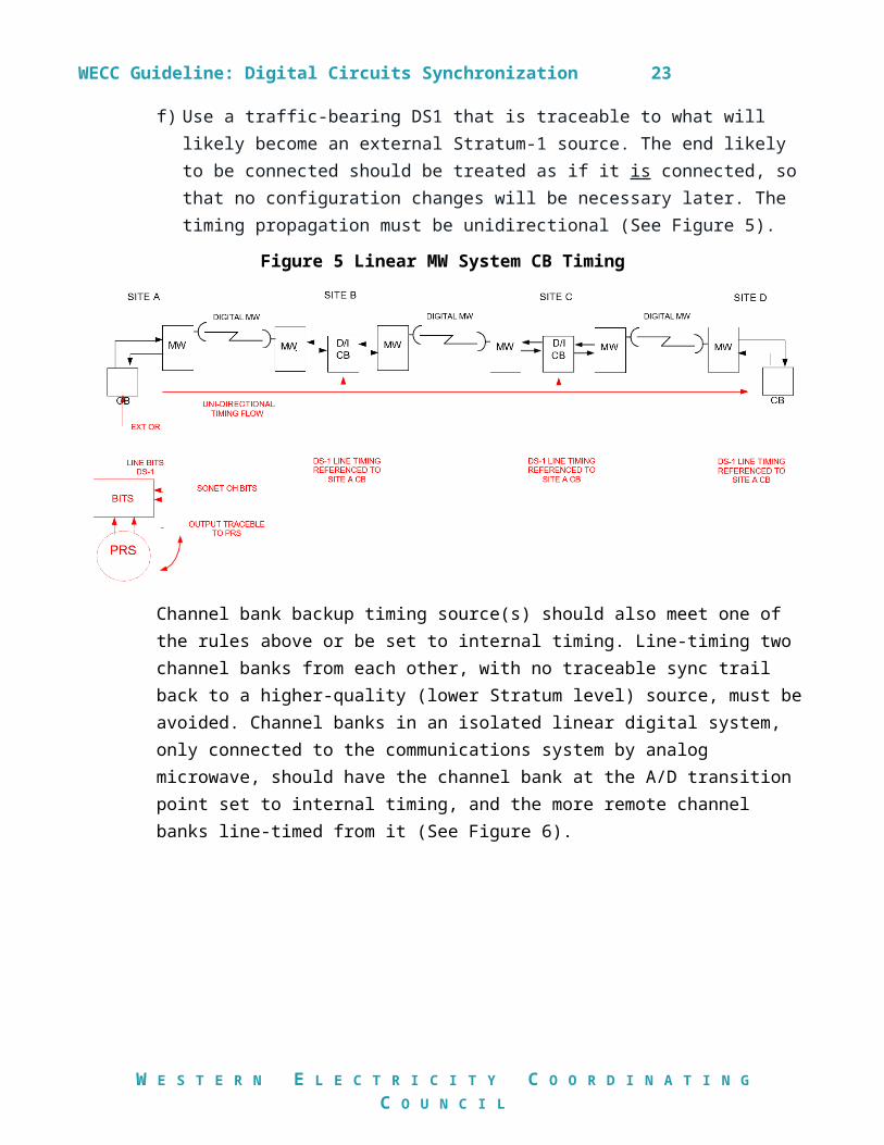
f) Use a traffic-bearing DS1 that is traceable to what will likely become an external Stratum-1 source. The end likely to be connected should be treated as if it is connected, so that no configuration changes will be necessary later. The timing propagation must be unidirectional (See Figure 5).
Figure 5 Linear MW System CB Timing
Channel bank backup timing source(s) should also meet one of the rules above or be set to internal timing. Line-timing two channel banks from each other, with no traceable sync trail back to a higher-quality (lower Stratum level) source, must be avoided. Channel banks in an isolated linear digital system, only connected to the communications system by analog microwave, should have the channel bank at the A/D transition point set to internal timing, and the more remote channel banks line-timed from it (See Figure 6).
Figure 6 Isolated Linear MW System CB Timing
W E S T E R N E L E C T R I C I T Y C O O R D I N A T I N G C O U N C I L

WECC Guideline: Digital Circuits Synchronization 19
D. Managing Synchronization
1. General – local and remote monitoring and configuration of synchronization is essential to maintaining a stable communications network. An FCAPS-compliant management system is preferred.
2. Alarm monitoring – PRS and BITS/SSU equipment should have contact closures for minor and major alarms.
3. Local Equipment interfaces – PRS and BITS/SSU equipment should be capable of interrogation for system monitoring and configuration. Autonomous Event and Alarm reporting should be available with a time stamp.
4. Remote Equipment interfaces – equipment should be accessible for monitoring, configuration, or event/alarm reporting through an Ethernet or EIA- 232 port.
5. A graphical representation of the timing system should exist as a screen imbedded in the NMS or as separate drawings.
6. Performance monitoring – to ensure the network is operating in synchronization; performance monitoring techniques should be applied by comparing a live signal to a known, good sync signal using the appropriate equipment with alarming and monitoring capabilities.
W E S T E R N E L E C T R I C I T Y C O O R D I N A T I N G C O U N C I L

WECC Guideline: Digital Circuits Synchronization 20
XI. Inter-Utility Synchronization
Typically, digital TDM interfaces with other utilities are at DS1 or DS0 levels. However, higher-order, inter-utility interfaces such as DS3, or even SONET OC-N, are possible. This section outlines the requirements for successful plesiochronous, digital circuit interfacing with foreign utilities.
A. Examples of Plesiochronous interfaces.
1. Floating DS1: A foreign utility passes a DS1 to a local utility. The DS1 may “float” through the local utility’s SONET or digital MW system untimed or not referenced to the local PRS (see Figure 7). Even though the DS1 is floated through an intermediate utility, each utility’s network should have at least one PRS per Section IV-A.1.
Figure 7 Floating DS1
W E S T E R N E L E C T R I C I T Y C O O R D I N A T I N G C O U N C I L

WECC Guideline: Digital Circuits Synchronization 21
2. Intermediate Timed DS1 : A foreign utility’s DS1 is groomed through a local utility’s intermediate DCS that is timed from or referenced to the local utility’s PRS (see Figure 8). This requires both utilities to use high-level synchronization (see Section V-B) or slips will occur on the DS1.
Figure 8 Intermediate Timed DS1
3. Terminated DS1 : A local utility owns and operates digital telecom end equipment (such as a channel bank or DCS) at one end of DS1 circuit that interfaces with a foreign utility’s channel bank at the other end of the circuit (see Figure 9). This requires the foreign utility to be in synchronization with the channel bank or DCS timing. It is recommended that the clocking master be the highest Stratum clock with the least number of hops to the utility interface point.
Figure 9 Terminated DS1
W E S T E R N E L E C T R I C I T Y C O O R D I N A T I N G C O U N C I L

WECC Guideline: Digital Circuits Synchronization 22
4. DS0 : A local utility owns and operates digital telecom end equipment that interfaces with foreign utility equipment at a synchronous 64 Kbps DS0 level. This DS0 interface could be between two local channel banks or a channel bank and a DCS or higher-level multiplexer (see Figure 10). The 64 Kbps interface could be EIA-530, G.703, or C37.94. This requires the foreign utility to be in synchronization with the channel bank timing.
Figure 10 Terminated DS0
5. Nx64 Kbps : A local utility owns and operates digital telecom end equipment that interfaces with foreign utility equipment at a synchronous Nx64 Kbps level. This interface could be between two local channel banks or a channel bank and a higher-level multiplexer or DCS. The Nx64 Kbps interface could be G.703 or C37.94. This requires the foreign utility to be in synchronization with the channel bank timing.
6. SONET OC-N : A foreign utility has a node onto a local utility’s ring or has a subtended ring from the local utility’s ring.
B. Plesiochronous Interface Synchronization Requirements
Plesiochronous interface points exist between utilities. The following is required to reduce jitter and wander on interconnected circuits, and to allow successful digital communication:
1. Each utility must follow Section IV synchronization planning.
2. Each utility shall have a Stratum-1 PRS or distributed Stratum-1 GPS BITS clock sources. For a radial network between utilities away from core SONET networks, it is recommended that a local PRS or retiming clock is provided for synchronization at the inter-utility interface site (see Figures 11 and 12). An interface PRS is optional for voice frequency (VF) or asynchronous, inter-utility DS0 circuits (see Figure 13).
W E S T E R N E L E C T R I C I T Y C O O R D I N A T I N G C O U N C I L
WECC Guideline: Digital Circuits Synchronization 23
Figure 11 Inter-utility DS1 Interface PRS
Figure 12 Inter-utility DS1 Interface Retiming
Figure 13 Inter-utility DS0 Interface PRS
W E S T E R N E L E C T R I C I T Y C O O R D I N A T I N G C O U N C I L

WECC Guideline: Digital Circuits Synchronization 24
3. Each utility shall use synchronization rules similar to Section IV-C. Pay special attention to the channel bank synchronization rules, described in Section IV-C-9, to avoid timing loops and have timing that is traceable to a Stratum-1 source.
4. If a communication system fails, each utility’s telecom equipment shall be able to automatically reconfigure timing reference sources to maintain traceability to a Stratum-1 PRS. See Section IV-B-2&3 for use of Sync Status Messaging.
5. DS1 circuits should be tested to ensure they meet the following criteria:
a) DS1s must meet ANSI T1.403 section 5.2 requirements on specifications such as transmission line rate + ppm, pulse shape, pulse imbalance, and power level.
b) B8ZS line coding should be used instead of AMI.
c) Super framing (SF) or ESF framing can be used, though each utility involved in the DS1 transport must agree on which framing to use.
d) DS1 timing jitter amplitude and wander, measured at either side of the inter-utility plesiochronous interface, shall not exceed unit interval (UI) limits specified in ANSI T1.403 section 6.3.
i. The DS1 signals should be compared with or reference a local Stratum-1 source for jitter and wander limits. Ideally, a local cesium source, portable or permanent, should be used as the reference.
6. C37.94 optical interface is recommended for Nx64 Kbps applications. Separate transmit and receive timing signals are not used, as timing is embedded within the information signals. This simplifies the interface and reduces master/slave clock contention issues. The optical interface also isolates a local utility’s communications ground reference from a foreign ground reference. If a C37.94 interface is not possible, a G.703 interface is the next option.
7. Due to strict timing requirements, utilities must inform each other when significant synchronization changes, which could affect the performance of inter-utility digital circuits, are planned (i.e.; a local utility retiming a previously floating DS1 by grooming the DS1 using a DCS or channel bank) (See Figure 7).
8. RS-232 interfaces should have all the control leads available to allow full “handshaking” between the utilities.
9. As a last resort, back-to-back VF interfaces can be used when synchronization issues cannot be resolved.
10. RS-422, RS-449, and RS-485 are becoming obsolete and are not described here.
W E S T E R N E L E C T R I C I T Y C O O R D I N A T I N G C O U N C I L

WECC Guideline: Digital Circuits Synchronization 25
XII. Appendix A — References
1. ANSI T1.105.03-2003, “Synchronous Optical Network (SONET) Jitter and Wander at Network and Equipment Interfaces.”
2. ANSI T1.105.09-1996 (R2002), “Synchronous Optical Network (SONET) Network Timing and Synchronization.”
3. ANSI T1.TR.81-2003, “Synchronization Network Architecture.”
4. ANSI T1.403, “Network and Customer Installation Interfaces – DS1 Electrical Interface.”
5. ITU-T Recommendation G.803, Mar. 2000, “Architecture of transport networks based on the synchronous digital hierarchy (SDH).”
6. ITU-T Timing Recommendation G.810, Aug. 1996, “Definitions and terminology for synchronization networks.”
7. ITU-T Recommendation G.811, Sept. 1997, “Timing requirements at the output of primary reference clocks suitable for plesiochronous operation of international digital links.”
8. ITU-T Recommendation G.812, June 1998, “Timing requirements of slave clocks suitable for use as node clocks in synchronization networks.”
9. ITU-T Recommendation G.813, Mar. 2003, “Timing characteristics of SDH equipment slave clocks (SEC).”
10. ITU-T Recommendation G.824, Mar. 2000, “The control of jitter and wander within digital networks which are based upon the 1544 Kbps hierarchy.”
11. ITU-T Recommendation G.825, Mar. 2000, “The control of jitter and wander within digital networks which are based upon the synchronous SDH hierarchy.”
12. Telcordia GR-253, Rev.2, Jan. 1999, “Synchronous Optical Network (SONET) Transport Systems: Common Generic Criteria.”
13. Telcordia GR-378, Feb. 1999, “Generic Requirements for Timing Signal Generators.”
14. Telcordia GR-436, June 1996, “Digital Network Synchronization Plan.”
15. Telcordia GR-499, “Transport Systems Generic Requirements (TSGR) Common Requirements.”
16. Telcordia GR-1244, May 2005, “Clocks for the Synchronized Network: Generic Criteria.”
17. Telcordia GR-2830, Dec. 1995, “Primary Reference Sources: Generic Requirements.”
18. Oscilloquartz Application Note, 06/96, “Synchronisation of the Digital Telephony Network and the Plesiochronous Digital Hierarchy.”, Figure 4.
W E S T E R N E L E C T R I C I T Y C O O R D I N A T I N G C O U N C I L

WECC Guideline: Digital Circuits Synchronization 26
Approved By:
Approving Committee, Entity or Person Date
Technical Operations Subcommittee
Telecommunications Work Group
W E S T E R N E L E C T R I C I T Y C O O R D I N A T I N G C O U N C I L