digital design: interfacing circuits between the logic gates of same family, different families and...
TRANSCRIPT

Chapter 7
Interfacing Circuits between the Logic Gates Of Same Family, Different Families and Types

Lesson 2
Interconnection of an output of a gate
with input of another gate

Ch07L2-"Digital Principles and Design", Raj Kamal, Pearson Education, 2006 3
Outline
•• Magnitude and Direction of Magnitude and Direction of Source and Sink CurrentsSource and Sink Currents
• Considerations of Fan-In and Fan-Out

Ch07L2-"Digital Principles and Design", Raj Kamal, Pearson Education, 2006 4
Current Flow
• A current flow takes place (as in any electronic circuit) howsoever small it may be
• Amount of current flowing will depend upon output at the gate and input of second gate

Ch07L2-"Digital Principles and Design", Raj Kamal, Pearson Education, 2006 5
Current Flow
• Current always takes the easiest path (least resistance)
• Direction of this flow will depend on output logic state 1 or 0
Ch07L2-"Digital Principles and Design", Raj Kamal, Pearson Education, 2006 6
Direction when output = 1
• The transistor at the output stage is OFF (does not conduct). Therefore, the current isource is sourced towards the input of interconnecting gate

Ch07L2-"Digital Principles and Design", Raj Kamal, Pearson Education, 2006 7
LSTTL isource (Logic state 1)Output transistor in cut off state
Rc
Ri
VCC
VEE

Ch07L2-"Digital Principles and Design", Raj Kamal, Pearson Education, 2006 8
Direction when output = 0
• Transistor at the output is ‘ON’(saturation state and does conduct). Therefore, the isink is sinking through it.

Ch07L2-"Digital Principles and Design", Raj Kamal, Pearson Education, 2006 9
LSTTL isink (Logic state 0)Output transistor in saturation state
Rc
Ri
VCC VCC

Ch07L2-"Digital Principles and Design", Raj Kamal, Pearson Education, 2006 10
Outline
• Magnitude and Direction of Source and Sink Currents
• Considerations of Fan-In and Fan-Out

Ch07L2-"Digital Principles and Design", Raj Kamal, Pearson Education, 2006 11
74 Standard TTL • isource = 40 µA • Fan-in at 1 with respect to 74xx = 1• isink = –1600 µA • Fan-in at 0 with respect to 74xx = 1• Fan-out to 74xx = 10• Fan-out to 74LSxx = 20• IOH and IOL= 400 µA and –1600 µA
Ch07L2-"Digital Principles and Design", Raj Kamal, Pearson Education, 2006 12
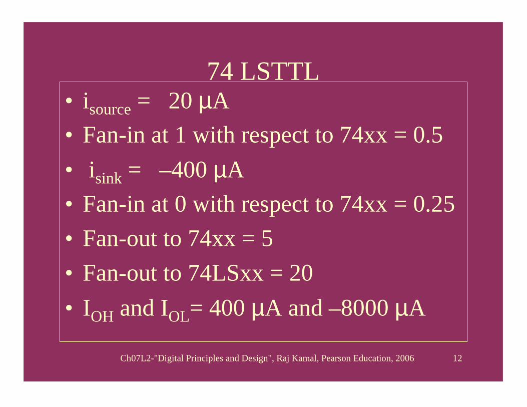
74 LSTTL • isource = 20 µA • Fan-in at 1 with respect to 74xx = 0.5• isink = –400 µA • Fan-in at 0 with respect to 74xx = 0.25• Fan-out to 74xx = 5• Fan-out to 74LSxx = 20• IOH and IOL= 400 µA and –8000 µA

Ch07L2-"Digital Principles and Design", Raj Kamal, Pearson Education, 2006 13
40.. • isource = 1 µA • Fan-in at 1 with respect to 74xx = 0.025• isink = –40 µA • Fan-in at 0 with respect to 74xx = 0.025• Fan-out to 74xx = 0.5• Fan-out to 74LSxx = 1• IOH and IOL= 10 µA and –500 µA
Ch07L2-"Digital Principles and Design", Raj Kamal, Pearson Education, 2006 14
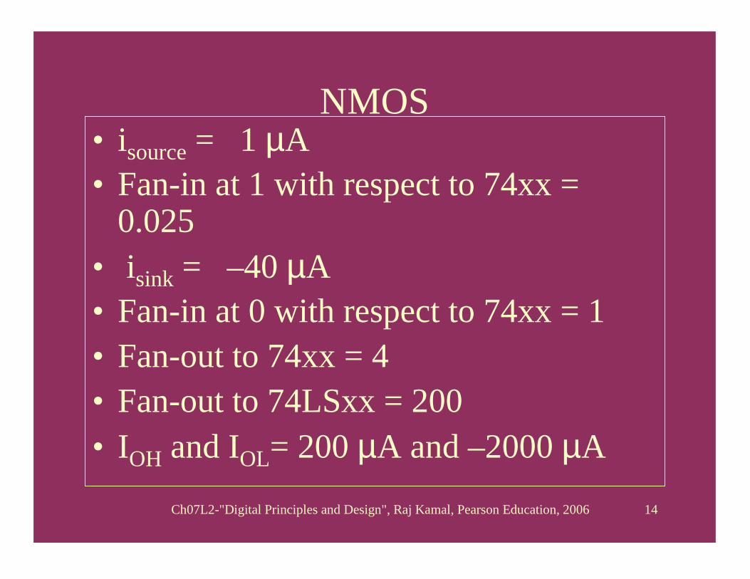
NMOS• isource = 1 µA • Fan-in at 1 with respect to 74xx =
0.025• isink = –40 µA • Fan-in at 0 with respect to 74xx = 1• Fan-out to 74xx = 4• Fan-out to 74LSxx = 200• IOH and IOL= 200 µA and –2000 µA

Ch07L2-"Digital Principles and Design", Raj Kamal, Pearson Education, 2006 15
FanFan--InIn• isource from a standard TTL twice as
large than LS TTL, and 10 times as large than from a CMOS 40... family gates
• isink in a standard TTL gate is four times than in a LS TTL gate. The reciprocal of it can be called fan-in.

Ch07L2-"Digital Principles and Design", Raj Kamal, Pearson Education, 2006 16
FanFan--InIn• A measure of isource and isink with
respect to a standard TTL family gate at the input. Fan in is different in the states ‘1’ and in state ‘0’ for the TTL family gates.
• Same for ‘1’ and ‘0’ in CMOS family gates

Ch07L2-"Digital Principles and Design", Raj Kamal, Pearson Education, 2006 17
Fan-in for various families of gates
• Fan-in for 74LS family at ‘1’ is 0.5 as isource (20µA) is half of the value (40µA) when standard TTL will be the input. Fan in for LS family at ‘0’ is 0.25 as isink is one fourth (400µA) from it compared to the value (1600µA) from a standard TTL gate at the input.

Ch07L2-"Digital Principles and Design", Raj Kamal, Pearson Education, 2006 18
LSTTL Fan-in (Logic state 1 )
Output transistor in cut-off state
Rc
Ri
VCC
VEMaxi-mum
20 inputs
can connect
Ch07L2-"Digital Principles and Design", Raj Kamal, Pearson Education, 2006 19
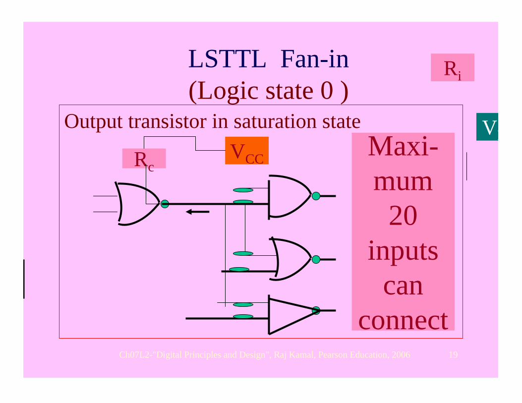
LSTTL Fan-in (Logic state 0 )
Output transistor in saturation state
Rc
Ri
VCC
VEMaxi-mum
20 inputs
can connect

Ch07L2-"Digital Principles and Design", Raj Kamal, Pearson Education, 2006 20
Fan-in for various families of gates
• For CMOS 40… series gate Fan-in at ‘1’ and ‘0’ only 0.025 as isource is 40µA multiplied by 0.025 = 1µA), and isink is 1600µA multiplied by 0.025 =. 40µA.
Ch07L2-"Digital Principles and Design", Raj Kamal, Pearson Education, 2006 21
Fan-Out
• The number of input next input stages, which can be connected to a given type of a logic gate
• Defined for an output logic gate in terms of the identical gates or in terms of standard TTL gates or in terms of LSTTL gates as the next stage(s) inputs.

Ch07L2-"Digital Principles and Design", Raj Kamal, Pearson Education, 2006 22
Summary

Ch07L2-"Digital Principles and Design", Raj Kamal, Pearson Education, 2006 23
• Considerations of source and sink current required at an output of a gate determine fan-in and fan-outs and determine whether interconnection feasible or not without any external voltage pull up and pull down resistances

Ch07L2-"Digital Principles and Design", Raj Kamal, Pearson Education, 2006 24
End of Lesson 3 on Interconnection of an output of a gate
with input of another gate

Ch07L2-"Digital Principles and Design", Raj Kamal, Pearson Education, 2006 25
THANK YOU