differentiating series and parallel photovoltaic...
TRANSCRIPT

Differentiating Series and Parallel Photovoltaic Arc-Faults
Jay Johnson1, Michael Montoya
1, Scott McCalmont
2, Gil Katzir
2, Felipe Fuks
2,
Justis Earle2, Armando Fresquez
1, Sigifredo Gonzalez
1, and Jennifer Granata
1
1Sandia National Laboratories, Albuquerque, NM, 87185, USA
2Tigo Energy, Los Gatos, CA, 95032, USA
Abstract — The 2011 National Electrical Code® requires PV
DC series arc-fault protection but does not require parallel arc-
fault protection. As a result, manufacturers are creating arc-
fault circuit interrupters (AFCIs) which only safely de-energize
the arcing circuit when a series arc-fault occurs. Since AFCI
devices often use the broadband AC noise on the DC side of the
PV system for detection and series and parallel arc-faults create
similar frequency content, it is likely an AFCI device will open in
the event of either arc-fault type. In the case of parallel arc-
faults, opening the AFCI will not extinguish the arc and may
make the arc worse, potentially creating a fire. Due to the fire
risk from parallel arc-faults, Tigo Energy and Sandia National
Laboratories studied series and parallel arc-faults and confirmed
the noise signatures from the two arc-faults types are nearly
identical. As a result, three alternative methods for
differentiating parallel and series arc-faults are presented along
with suggestions for arc-fault mitigation of each arc-fault type.
Index Terms — photovoltaic systems, arc-fault detection, series and parallel arc-faults, sensors, monitoring, power system safety
I. INTRODUCTION
The 2011 National Electrical Code® (NEC) [1] requires
series arc-fault protection, but does not require parallel arc-
fault detection or mitigation. Series arc-faults are created when
there is a discontinuity in a conductor and the current bridges
this gap. Parallel arc-faults are created when an arc is
established between conductors at different potentials.
Though there are many potential parallel arc-fault paths, three
generic types of parallel arc-faults are shown in Figure 1.
These parallel arc-faults include:
1. Parallel Arc-Fault to Grounded Conductor – This parallel
arc-fault could result from the negative DC cable (often
grounded in the USA) shorting to a positive conductor
due to wear, rodent bites, or damage to cables in conduit
runs. In the case of the Mount Holly, NC fire [2] and the
Bakersfield, CA fire [3], the fault path was established
through the grounded current-carrying conductor via two
faults to the conduit.
2. Cross-String Parallel Arc-Fault – This fault occurs when
conductors on different strings at different potentials arc.
3. Intra-String Parallel Arc-Fault – This parallel arc-fault
can occur anywhere in the string where a short occurs,
e.g., in junction boxes [4].
Fig. 1. Different types of parallel arc-faults on the DC side of a PV array.
Currently a number of companies are developing series arc-
fault protection devices [5-6]. Many Arc-Fault Circuit
Interrupters (AFCIs) use elevated AC noise on the DC side of
the PV system to detect series arc-faults. The difficulty comes
in differentiating series and parallel arc-faults because the
noise signatures are similar. Additionally, many AFCIs are
designed to be installed at the string or array-level [7] so if a
parallel arc-fault causes the AFCI to trip, the arc will not be
extinguished and may strengthen as more current is directed
through the arc-fault path. As a result, it is imperative that
AFCIs make the appropriate corrective action when an arc-
fault occurs.
At this point, there is no consensus on a method for
determining which type of arc-fault is present in the PV
system. Strobl and Meckler proposed that parallel arc-faults
could be identified by the large change in current [8].
However, it may be difficult to differentiate shading from a
fast moving cloud or plane from a parallel arc-fault if the
current is monitored alone. Another option may be to use the
voltage to identify parallel arc-faults, but in the case of intra-
string parallel arc-faults across a single module, this change in
voltage would be no different from one bypass diode
engaging.
Other questions exist about how to effectively extinguish
parallel arc-faults. Häberlin proposed to have the AFCI open
the string to extinguish the series arc-fault, then, if the arcing
frequencies still exist, short the string to extinguish the parallel
arc-fault [9]. This methodology would prevent most parallel
arc-faults, but special attention would need to be paid to the
case of cross-string parallel arc-faults because both strings
must be shorted. SMA has recommended isolation monitoring
to prevent parallel faults [10], but they believe module-level
shorting is required to stop a parallel arc-fault [11]. Johnson
also suggested shorting the modules when parallel arc-faults
were identified [6], although this still leaves the system
energized at the maximum current (Isc) until night—or
otherwise shaded—when the defective components can be
replaced.
The goal of this work is to identify electrical conditions
which differentiate parallel and series arc-faults and to suggest
a prevention methodology for incorporation into arc-fault
circuit protection tools. First, we model different parallel arc-
faults using single diode module models. These models show
a need for experimental analysis as accurate simulations of the
system with arc-faults is difficult. Experiments were
performed with Tigo Energy at the Distributed Energy
Technologies Laboratory (DETL) at Sandia National
Laboratories using Tigo Energy’s Arc-Fault Detector (AFD).
Though designed specifically for series arc-faults, the AFD
detected parallel and series arc-faults because the frequency
content of the different arc-fault types were nearly identical.
Lastly, we present three methods for differentiating series and
parallel arc-faults and suggest appropriate actions to mitigate
the risk of electrical fires from parallel arc-faults.
II. PARALLEL ARC-FAULT MODEL
Modeling the effect of a parallel arc-fault on a PV string is
challenging because of the variability in location, strength, and
duration of the arc-fault. Using a standard single diode PV
model [12] and basic inverter model [13], the effects of the
different parallel arc-faults were studied. We assume the
modules have bypass diodes, and operate at VMPP = 50 V and
IMPP = 3 A, and the inverter acts as a resistive load operating at
the maximum power point (MPP) with effective resistance of
60 . (We later show this inverter model captures the
behavior of a load bank well but is insufficient for arc-faults
with an inverter.)
For a parallel arc-fault to the grounded conductor, shown in
Fig. 1, the PV string current is split between the inverter and
the arc-fault path. The parallel arc-fault is fed differently
depending on the inverter components, topology, MPP
tracking (MPPT) algorithm, module I-V curves, and the arc-
fault impedance. The current is divided between the inverter
and arc resistances according to,
arc
MPP
inverter
MPParcinverterMPP
R
V
R
Viii
66 (1)
where Rinverter is the effective MPP resistance of the inverter
and Rarc is the arc resistance. The exact division of current is
difficult to predict, as the arc resistance is nonlinear and
dependent on gap length, electrode material, arc current, and
electrode geometry [14]. During this parallel arc-fault case,
since Rarc is generally smaller than Rinverter, monitoring the
current change at the inverter would detect the arc-fault. Note
that this is the only test case required for Type 2 devices
(parallel arc-fault detectors) in UL Subject 1699B [15].
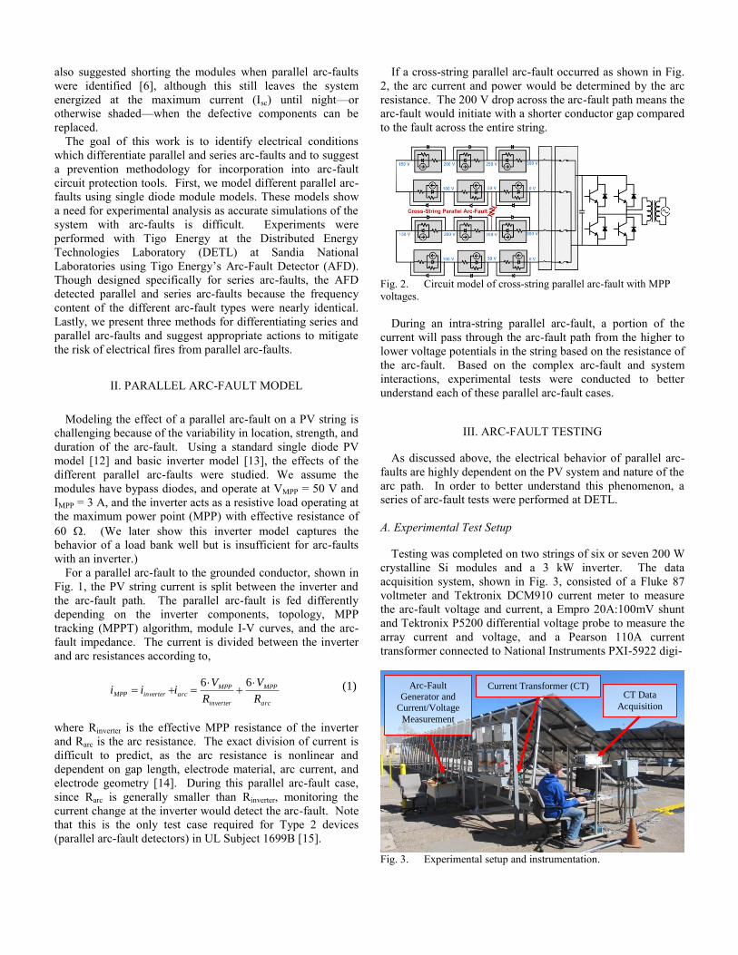
If a cross-string parallel arc-fault occurred as shown in Fig.
2, the arc current and power would be determined by the arc
resistance. The 200 V drop across the arc-fault path means the
arc-fault would initiate with a shorter conductor gap compared
to the fault across the entire string.
Fig. 2. Circuit model of cross-string parallel arc-fault with MPP
voltages.
During an intra-string parallel arc-fault, a portion of the
current will pass through the arc-fault path from the higher to
lower voltage potentials in the string based on the resistance of
the arc-fault. Based on the complex arc-fault and system
interactions, experimental tests were conducted to better
understand each of these parallel arc-fault cases.
III. ARC-FAULT TESTING
As discussed above, the electrical behavior of parallel arc-
faults are highly dependent on the PV system and nature of the
arc path. In order to better understand this phenomenon, a
series of arc-fault tests were performed at DETL.
A. Experimental Test Setup
Testing was completed on two strings of six or seven 200 W
crystalline Si modules and a 3 kW inverter. The data
acquisition system, shown in Fig. 3, consisted of a Fluke 87
voltmeter and Tektronix DCM910 current meter to measure
the arc-fault voltage and current, a Empro 20A:100mV shunt
and Tektronix P5200 differential voltage probe to measure the
array current and voltage, and a Pearson 110A current
transformer connected to National Instruments PXI-5922 digi-
Fig. 3. Experimental setup and instrumentation.
Arc-Fault
Generator and
Current/Voltage
Measurement
CT Data
Acquisition
Current Transformer (CT)

tizer to perform real-time FFT measurements of string current,
monitor inverter and arcing noise, and record noise signatures.
The arc-fault generator (AFG) [7] was installed between
modules using MC4 T-branch connectors.
B. Series Arc-Faults
Series arc-faults occur in the electrical circuit of the PV
system due to corrosion or other conductor discontinuities.
Series arc-faults differ from parallel arc-faults in that the string
current and voltage only vary slightly from normal operation
[6] and the location of the arc-fault also does not change the
string current or voltage, shown in Fig. 4. The Tigo Energy
AFD was tested for series arc-fault detection on multiple
inverters and using a load bank. One test with the trip signal
is shown in Fig. 5.
Fig. 4. Series arc-faults at different locations with an inverter. The
current drift over the test is due to decreasing irradiance. For the
locations, ―7+‖ refers to the positive conductor of the 7th module
counted from the grounded negative DC conductor. ―5-6‖ refers to
an arc-fault generated between modules 5 and 6.
Fig. 5. Example data from a series arc-fault test showing 219 ms
trip time.
During testing, generating arc-faults with the load bank was
not challenging, however generating arc-faults with the
inverter was difficult if string lengths were not sufficient.
Series arc-faults could not be sustained using a 3 kW inverter
with two strings of six modules, but with 7-module strings,
arcs were repeatedly drawn by separating two Cu electrodes.
The ignition difficulty in the smaller system was because the
maximum voltage available to the arc is Voc minus Vmpp since
the DC smoothing capacitor in the inverter is charged to Vmpp.
Thus, if the voltage drop over the arc-fault gap becomes
greater than Voc - Vmpp the faulted string reaches Voc and there
is no long any string current. The dielectric strength of air is
large until the arc ionizes the atmosphere, so by using the
hand-operated arc-fault generator, the gap tolerance could not
be controlled well enough to establish the arc with six
modules per string. As a result, it is possible that for some
inverters the input capacitor could act as a series arc-fault
protection device.
C. Parallel Arc-Faults
Parallel arc-fault tests were completed with a resistive load
bank and with an inverter. The load bank resistance was set to
near the maximum power point (MPP) of two parallel strings
of six modules. Parallel arc-faults to the grounded conductor,
intra-string, and cross-string parallel arc-faults were generated.
The Fast Fourier Transform (FFT) of the DC line current from
0-100 kHz with a Hanning window is shown in Fig. 6. The
noise generated by the different parallel arc-faults and a series
arc-fault (black trace) are similar. It is unlikely that an arc-
fault detector would be able to differentiate series and parallel
arc-faults sensing current frequencies alone.
As described in Section II, the parallel arc-fault establishes a
2nd current loop in the PV system, so a portion of the PV
power passes through the parallel arc-fault as opposed to the
load bank or inverter. As shown in the 1-second data in Fig.
7, the percentage of this current and voltage is dependent on
the location of the parallel arc-fault. Fig. 7 also shows that the
resistance of the arc-fault is much smaller than the load bank
because nearly all of the current passes through the low
resistance arc-fault path. This closely matches the behavior
described by Eq. (1) when Rarc << Rinverter.
Fig. 6. Different parallel arc-fault noise signatures compared to a
series arc-fault. Data are smoothed with 800 Hz rectangular-sliding
average.

Fig. 7. Current and voltage changes at the load bank due to parallel
arc-faults.
In Table I, the system currents and voltages are shown for
various parallel arc-faults. Connections to the modules were
made at the positive conductor. The load bank current and
voltage (ILB, VLB) are given as the range of values during AFG
bypass, conduction through the electrodes, and during the arc-
fault. The larger values are at the time of the sustained arc-
fault. As seen in the table, the arc voltage is consistent for all
the cases because the arc-gap was nearly the same for all the
tests. Increasing the gap would have increased the arc voltage
and produced higher levels of AC noise on the system. The
arc-fault path has low impedance compared to the load bank
so nearly all the available current travels through the arc-fault.
Thus, the current through the arc-fault is principally dependent
on the number of modules that are shorted, regardless of the
type of parallel arc-fault. The remaining PV-generated current
passes through the load bank and the voltage drop across the
load is related proportionally by Ohm’s law.
TABLE I. ARC AND LOAD BANK CURRENT AND VOLTAGE
VALUES DURING DIFFERENT PARALLEL ARC-FAULTS
Varc (V) Iarc (A) VLB (V) ILB (A)
Near MPP without Arc-Fault 0 0 317 7.2 Module 1 to Negative Conductor * * 289-317 6.6-7.2
Module 2 to Negative Conductor 22 2.4 245-262 5.5-6.0
Module 3 to Negative Conductor 18 3.7 191-206 4.4-4.7 Module 4 to Negative Conductor 18 5.0 132-150 3.0-3.4
Module 5 to Negative Conductor 18 6.5 67-87 1.6-2.0
Module 6 to Negative Conductor 18 8.1 0-20 0.0-0.5 Module 1 to Module 2 * * 288-314 6.5-7.1
Module 1 to Module 3 22 1.8 243-261 5.5-5.9
Module 1 to Module 4 20 3.3 191-208 4.3-4.7 Module 1 to Module 5 18 4.8 130-154 3.0-3.5
Module 1 to Module 6 20 6.1 68-87 1.5-2.0
Module 5 to Module 6 * * 284-310 6.5-7.0 Module 3 to Module 6 on 2nd String 20 4.6 133-151 3.0-3.4
Module 4 to Module 6 on 2nd String 20 3.3 187-207 4.3-4.7
* Unsustained or sputtering arc-fault.
Parallel arc-faults were also generated on two strings of
seven modules with a 3 kW high frequency inverter. In these
tests, the string conductors were joined with T-branch
connectors before the DC disconnect. The configuration
created a conductive loop which acted as an antenna and also
allowed baseline and arc-fault noise to propagate in the array
with DC disconnect open. As a result, there were more spikes
in the baseline spectrum between 0-300 kHz and, when the
inverter was running, there was noise at the switching
frequency and its harmonics, shown in Fig. 8. As with the
resistive load bank tests, the parallel and series arc-fault noise
were similar. The parallel arc-fault from Module 7 to the
negative conductor was not performed because shorting the
input capacitor to the inverter was believed to be potentially
dangerous.
Fig. 8. FFT of string current during parallel and series arc-faults
with a 3 kW inverter. Data smoothed with 400 Hz rectangular
sliding-average.
The string current and voltage during the inverter test cases
were completely different than those presented in Table I. As
shown in Fig. 9, the voltage across the inverter was related to
the number of modules that were shorted by the arc-fault path,
similar to the load bank tests. However, in all cases, the
current to the inverter dropped to zero when parallel arc-faults
were generated. This may be a result of the test sequence: the
electrodes were briefly touched together and then quickly
separated to establish the parallel arc-fault. This is different
than the UL 1699B standard which uses steel wool to create
the parallel arc-fault. By closing the electrodes very briefly,
the string becomes shorted and the inverter may stop
operating. This was the case except in the 1st Ground to 4+
arc-fault in Fig. 9. Another reason the inverter may turn off
during parallel arc-faults is there is little or no current reaching
the inverter. Each module was rated at Isc = 3.8 A and Immp =
3.5 A, but for all parallel arc-fault tests listed in Fig. 7, the
current through the arc fault was nearly 2Isc (4.4-6.3 A
depending on the time of day) meaning the 2nd
string was
back-feeding the parallel arc-fault through the bypass diodes
and the current path no longer included the inverter. Further
testing is required to determine if this is the case for all
parallel arc-faults with an inverter running. Different array
configurations (i.e., single string, multiple stings) should also
be tested.
Unfortunately, when the inverter shuts off during a parallel
arc-fault, it does not extinguish the arc-fault. Instead the arc
remains energized until the current flow stops, the arc self-

extinguishes by burning through the electrodes, or appropriate
action is taken by a ―Type 2‖ AFCI. Parallel arc-faults were
detected by the Tigo Energy AFD and tripped within 170-450
ms for the tests conducted at DETL, indicating arc-fault
detection of parallel arc-faults is possible. One example of
Tigo Energy’s AFD performing parallel arc-fault detection is
shown in Fig. 10.
Fig. 9. Parallel arc-fault current and voltage data at the inverter.
―Ground‖ refers to the grounded current-carrying conductor (the
negative DC string conductor).
Fig. 10. Parallel arc-fault current and voltage. Trip time was 235
ms.
III. DIFFERENTIATION OF SERIES AND PARALLEL
ARC-FAULTS
As shown above with the load bank and inverter tests,
discriminating parallel and series arc-faults is not possible
using the string frequency noise alone. Instead, additional
diagnostic sensors must be employed. Here we present three
methods to classify series or parallel arc-faults. This may be
necessary in order to take the appropriate action to de-energize
the different arc-faults.
Method 1: Use a combination of arc-fault high frequency
noise along with changes in current or voltage. First
suggested by Strobl and Meckler [8], parallel arc-faults are
often associated with a drop in current and voltage to the
inverter or charge controller (see Figs. 7 and 9), whereas series
arc-faults show little change in current or voltage on the string
(see Fig. 4). Based on the experimental work presented here,
these drastic current and voltage changes are unlikely to exist
from irradiance changes. However, in order to prevent false
diagnoses, a combination of arcing noise with a change in the
current and voltage is recommended. One potential problem
with this method is that if the inverter shuts off during a
parallel arc-fault, the arcing frequencies may not reach the arc-
fault detector and it would appear as though the system was
safely de-energized when, in fact, a parallel arc-fault is still
burning.
Method 2: Force the PV array to Voc and recheck arc-fault
noise. By pushing the arcing string off its maximum power
point (MPP), series arc-faults would be extinguished but
parallel arc-faults would continue. This could be done with
the inverter MPP Tracker adjusting the system toward Voc or
by physically inserting a resistance (R1) in the string. With the
additional resistance in the circuit, there is less current
available to sustain the series arc-fault, illustrated in Fig. 11.
With enough impedance, the current will drop enough that the
series arc-fault will be extinguished but a parallel arc-fault will
not, so by rechecking for arc-fault frequencies with R1 in the
circuit, a parallel arc-fault would be identified. Maintaining
the continuity of the circuit is critical to ensure the arc-fault
frequencies still reach the arc-fault detector. Opening the
circuit prevents the noise from propagating through the array,
thereby eliminating the possibility to recheck the system for
parallel arc-fault noise. Parallel arc-fault noise is
indistinguishable from baseline noise when the array is open,
shown in Fig. 12.
Cu
rre
nt
(A)
Voltage (V) Voc
Isc
Impp
Vmpp
Slope =
1/R
inverte
r
Slope = 1/(Rinverter + R1)
Fig. 11. Operation of the PV system normally and with high series
resistance.
The resistance, R1, required to extinguish the series arc-fault
will depend on the system. Experimental work with the load
bank showed that for a system with Rmpp = ~50 , Rinverter + R1
= 225 could sustain the arcs but at 450 the arc-fault was
difficult to sustain. At this same resistance, the parallel arc-
fault noise was easy to identify. The increase in resistance can
be performed with the inverter adjusting the MPP and would
add no additional costs to the PV system.

Fig. 12. Baseline and intra-string parallel arc-fault noise. Parallel
noise is not present when the string is open.
Method 3: Permanently connect parallel strings to
establish a noise path to the AFD. When two or more PV
strings are connected using T-branch connectors or solid
connections at the combiner box, a loop in the PV system
allows the arc-fault noise to reach the arc-fault detector even
when the DC disconnect at the combiner box or inverter is
open. When the disconnect is open, parallel arc-fault noise
will reach the arc-fault detector but series arc-faults will be
extinguished. An illustration of the configuration is shown in
Fig. 13. An example of parallel arc-fault noise with the
disconnect open is shown in Fig. 8. Thus, series and parallel
arc-faults could be differentiated and de-energized using the
procedure:
1. When arc-fault noise is detected, open the DC
disconnect. (This de-energizes any series arc-fault.)
2. If the noise persists, the arc-fault noise is from a
parallel arc-fault and appropriate action can be taken.
T-Branch
T-Branch
Arc-Fault Detector
Arc-Fault Detector
Fig. 13. Method for series arc-fault to be extinguished, but parallel
arc-faults to remain active and detectable by the arc-fault detector.
Since this method guarantees series arc-faults will be
extinguished quickly with the opening of the dc disconnect(s),
it may be superior to Method 2.
IV. PARALLEL ARC-FAULT DE-ENERGIZATION
In order to de-energize a series arc-fault, it is fairly straight-
forward: the string must be opened at one or more locations to
prevent current flow to the arc. Unfortunately, the mitigation
routine for parallel arc-faults is less obvious. There are two
leading theories on how to extinguish parallel arc faults: open
connectors between each module or short the array. As shown
in Table II, either opening or shorting the array will extinguish
the parallel arc-fault cases listed in Fig. 1. Opening the
connectors between each module limits system voltages to the
open circuit voltage of a single module. Shorting the string or
each module effectively drops all the conductors to 0 V
ground potential and pushes the module operating points
toward ISC, where there is no voltage between conductors.
Without the gap voltage the parallel arc-fault will be
extinguished. This was confirmed at DETL by extinguishing
parallel arc-faults (i) on a string of three modules with an arc-
fault across the middle module and (ii) on a string of seven
modules with an arc-fault from Modules 2 to 6. In both cases
repeated parallel arc-faults with the string open were
immediately extinguished when the string was shorted.
In the case of a parallel arc-fault within a module, shown in
Fig. 14, opening the connectors (arrows) would not de-
energize the arc and the fault would continue with a gap
voltage of VOC/3. VOC for many modern modules is well
above 50 V so opening the connectors between the modules
would not reduce the voltage to a level which ensures arc-fault
suppression (~12 V).
Shorting the array or modules is not without its limitations
though. One concern with shorting portions of an active array
is the energy conducted through the switch could be high due
to the charge stored on the input capacitor of the inverter. To
prevent the capacitor energy from dumping into the system, an
additional series switch could be used to disconnect the
inverter, but this adds complexity and cost, and slows the
system response. Also, servicing an array that has been shut
down by shorting poses a challenge, as there is no reliable way
to eliminate current flowing through the string conductors.
Additionally, the shorting switch cannot be opened without
reestablishing the conditions for the arc-fault. The only safe
way would be to disconnect the string wiring when the array is
not exposed to sunlight, which would delay a full system shut
down.
Tigo Energy notes that there is considerable overlap in the
electronics required for the DC optimization of a module's
operating characteristics and an arc-fault detector. For a
TABLE II PARALLEL ARC-FAULT PROTECTION OPTIONS
Parallel Arc-Fault Location De-energization via
Opening Between Modules?
De-energization via
Shorting Between Modules?
De-energization via
Shorting the String?
To grounded conductor Yes Yes Yes
Cross-string Yes Yes Yes
Intra-string Yes Yes Yes

nominal additional cost, a detector could be integrated into
each junction box. Then any module that detects an arcing
signature could independently respond by opening the
module's output, which would immediately reduce the total
power available to sustain the arc-fault. Once the arc-fault is
extinguished, a central processor could collect the data from
the individual modules, analyze the results for arc-fault
patterns, and make a determination of whether a series or
parallel arcing has occurred. This processor could also safely
shut down the remainder of the array and provide notification
that an event has occurred
Fig. 14. High power PV module with internal arc-fault.
If parallel arc-fault protection is adopted in the 2014 NEC,
the Code will not state the method in which the parallel arc-
faults should be de-energized—simply that they must be.
Individual arc-fault circuit interrupter manufacturers will need
to determine the safest way to eliminate series and parallel
arc-fault hazards.
IV. CONCLUSIONS
Arc-fault detectors designed to satisfy National Electrical
Code 690.11 often use the frequency content of the PV DC
system to determine when a series arc-fault is established.
Unfortunately this method does not provide a means for
differentiating series and parallel arc-faults because the arc-
fault noise is similar for both arc-fault types. We present three
alternative methods for differentiating parallel and series arc-
faults and recommendations for the suppression of both arc-
fault cases. Once the arc-fault type is determined, series arc-
faults can be de-energized by opening the string at any point.
Many parallel arc-faults can be de-energized by opening
connectors between the modules and all parallel arc-faults can
be de-energized by shorting the modules or the strings.
Unfortunately, the shorting solution requires shorting the input
capacitor of the inverter and repairs to the array would require
shading the modules or working at night. Additional analysis
of different system configurations and appropriate AFCI
responses during parallel arc-fault events is recommended.
ACKNOWLEDGEMENT
Sandia National Laboratories is a multi-program laboratory
managed and operated by Sandia Corporation, a wholly owned
subsidiary of Lockheed Martin Corporation, for the U.S.
Department of Energy's National Nuclear Security
Administration under contract DE-AC04-94AL85000. This
work was partly funded by the US Department of Energy
Solar Energy Technologies Program and partly supported by
the National Renewable Energy Laboratory under subcontract
NEU-2-11979-03.
REFERENCES
[1] National Electrical Code, 2011 Edition, NFPA70, National Fire
Protection Association, Quincy, MA.
[2] B. Brooks, The Bakersfield Fire, SolarPro 4.2, Feb/Mar 2011.
[3] B. Brooks, Report of the Results of the Investigation of Failure
of the 1.1135 MW Photovoltaic (PV) Plant at the National
Gypsum Facility in Mount Holly, North Carolina. Brooks
Engineering Draft Report. 26 May, 2011.
[4] A. Schlumberger, A. Kreutzmann, Brennendes Problem –
Schadhafte BP-Module können Feuer entfachen, Photon, August
2006, pp. 104-106 (in German).
[5] T. Zgonena, L. Ji, and D. Dini, Photovoltaic DC Arc-Fault
Circuit Protection and UL Subject 1699B, Photovoltaic Module
Reliability Workshop, Golden, CO, Feb. 2011.
[6] J. Johnson and W. Bower, “Codes and Standards for
Photovoltaic DC Arc-Fault Protection,” Presentation for Solar
American Board for Codes and Standards, Dallas, TX, 21 Oct.,
2011.
[7] J. Johnson, B. Pahl, C.J. Luebke, T. Pier, T. Miller, J. Strauch, S.
Kuszmaul and W. Bower, “Photovoltaic DC arc fault detector
testing at Sandia National Laboratories,” 37th Photovoltaic
Specialists Conference, Seattle, WA, 19-24 June 2011.
[8] C. Strobl and P. Meckler, Arc Faults in Photovoltaic Systems,
2010 Proceedings of the 56th IEEE Holm Conference on
Electrical Contacts, pp.1-7, 4-7 Oct. 2010.
[9] H. Haeberlin, Arc Detector as an External Accessory Device for
PV Inverters for Remote Detection of Dangerous Arcs on the
DC Side of PV Plants, European Photovoltaic Solar Energy
Conference Valencia, Spain 2010.
[10] S. Bieniek, H. Behrends, G. Bettenwort, T. Bülo, A. Häring, M.
Hopf, M. Kratochvil, C. Merz, T. Wegener, Fire prevention in
PV plants using inverter integrated AFCI, 26th European
Photovoltaic Solar Energy Conference and Exhibition,
Hamburg, Germany, 2011.
[11] A. Häring and S. Bieniek, “Prevention and Detection of Arc
Faults in PV Systems,” Photon’s 2nd PV Safety Conference,
2011, Berlin, Germany
[12] H.-L. Tsai, C.-S. Tu, and Y.-J. Su. “Development of Generalized
Photovoltaic Model Using MATLAB / SIMULINK,”
Proceedings of the World Congress on Engineering and
Computer Science, 2008, pp. 0-5.
[13] J. Worden and M. Zuercher-Martinson, How Inverters Work:
What Goes on Inside the Magic Box, SolarPro, Apr/May 2009.
[14] R.F. Ammerman, T. Gammon, P.K. Sen, and J.P. Nelson, DC-
Arc Models and Incident-Energy Calculations, IEEE
Transactions on Industry Applications, Vol. 46, No. 5, pp.1810-
1819, September-October 2010.
[15] Underwriters Laboratories (UL) Subject 1699B, Outline of
Investigation for Photovoltaic (PV) DC Arc-Fault Circuit
Protection, April 29, 2011.
Short