diameter correction tool dct - オーエスジー株式会社 · diameter correction tool get...
TRANSCRIPT

DCT
Diameter Correction Tool
Get accurate values of the internal thread diameter at a glance!

1
■High-precision taper pipe threading (no stop marks)
■Thread cutting in drill holes with little allowance
Thread mills are ideal for the following
3 Support Tools for Your Thread Milling Needs
Airtight threads by having no stop marks Thread milling cuts the thread closer to the bottom of a hole than tapping, leaving only one incomplete crest of threadStop Marks
Reduce setup, machining time, and achieve stable tool life with these 3 support tools.
Thread Milling
ThreadProThread Milling NC Code
Generator Software
P.2 for details
2Diameter
Correction Tool for Thread Mills
P.3 for details
3
・ Available in 12 different languages.・ Supports 8 NC programming languages.・ Incorporates RPRG value to further
simplify process.
・ RPRG is the reference value of tool radius offset.
・ RPRG values are indicated on tool shank manufactured from November 2014.
・ Now possible to reduce the checking and correction simply by entering the RPRG value.
RPRGReference value of tool radius offset
1P.2 for details
・ The internal thread effective diameter, which used to be difficult to determine, can now be measured with readable values.
・ Measurable range from 100% ~ -50% tolerance of thread size (6H).
・ With an attached reading scale, the effective diameter's position can be confirmed at a glance.

2
RPRG is the reference value of tool radius offset.Conventionally, the tool radius was entered during setup as a parameter of the NC system, which was corrected by checking the thread with a gauge. However, it has become possible to reduce the checking and correction simply by entering the RPRG value indicated on the tool shank.
Example• Tool diameter:φ7.5; Pitch: 1; Minimum cutting bore diameter: 10 (EDP
No.:8304721)• Internal thread size: M10 × 1• Tolerance for pitch diameter: 0 to +0.118 (ISO-5H), 0 to +0.150 (ISO-6H)
Entered value of RPRG: 3.681
Entered value of Radius: 3.75
Pitch Dia. 0
ISO
-5H
Inte
rnal
Thr
ed
ISO
-6H
Inte
rnal
Thr
ed
+0.118
Radius
+0.150
RPRG=3.681
1
ThreadPro(Thread Milling NC Code Generator Software)2
● Notes1. RPRG is reference values. Optimal values for actual cutting depend on the machining environment.
Determine optimal values after trial cutting.2. RPRG values are optimally established to achieve ISO:5H (formerly Grade 1) internal thread limits for metric
threads and ANSI:3B internal thread limits for unified threads. RPRG values established for taper pipes (R/Rc) are effective when using the thread milling NC code generator software ThreadPro available on our website.
3. For diameters of thread mills, RPRG values are calculated based on the minimum cutting bore diameter (the minimum cutting internal thread size of the tool diameter). To cut other diameters, it is necessary to use a smaller value than RPRG.
4. RPRG values are indicated on tool shank manufactured from November 2014.
* Planet Cutter is a registered trademark of OSG Corporation.
RPRG(Reference value of tool radius offset)
Scan to download ThreadPro.
• Available in 12 different languages
• Supports 8 NC programming languages
• Incorporates RPRG* value to further simplify process* RPRG = reference value of tool radius offset
Powered by

3
The DCT is made up of three components – the thread plug, scale sleeve and bolt for fixing the position. Measurable range from 100% ~ -50% tolerance of thread size (6H); with 7 positions on the reading scale.
Get the value of the effective diameter at a glance by simply inserting the DCT into the thread and releasing the scale sleeve once it has reached the deepest position (for the correction of value in step processing of thread milling).
* The reading value should be used as reference only. To inspect the screw thread please use the limit gauge (refer to p.6).* Depending on work environment this product may not be applicable.
Effective diameter & position relationship diagramExample: M10×1
Specifications
Measuring Method
+0.150
+0.118
100%
50%
-50%
0 0
-0.075
+150
+75
0
-75
The internal thread effective diameter, which used to be difficult to determine, can now be measured with readable values.
6H5H
3 Diameter Correction Tool for Thread Mills
Insert the DCT into the thread. Turn the tool until it has reached the deepest position.
Turn the tool in reverse to remove it from the thread.
Read the value on the scale
Release the reading sleeve so that it touches the top of the thread. Fix the bolt by screwing it tight.
Thread plug Sleeve Handle
Bolt
1
3
2
4

4
EDP No. Thread Size Measurable Depth (mm) in Blind Hole Sleeve Dia. Stock Yen
9342018 5⁄16 - 24UNJF- 1.5D 11.9~ φ13 D 70,000
Specials (alternative thread sizes, modification of reading scale, etc.) available upon request.Contact your nearest OSG sales representative for more information.
D= Standard stock item
D= Standard stock item
EDP No. Thread Size Measurable Depth (mm) in Blind Hole Sleeve Dia. Stock Yen
9342000 M6 × 1 - 1.5 D 9 ~ φ13 D 50,000
9342001 M8 × 1.25 - 1.5 D 12 ~ φ13 D 51,000
9342002 M8 × 1 - 1.5 D 12 ~ φ13 D 49,600
9342003 M10 × 1.5 - 1.2 D 12 ~ φ15 D 51,600
9342004 M10 × 1 - 1.2 D 12 ~ φ15 D 51,600
9342005 M12 × 1.75 - 1.2 D 14.4 ~ φ17 D 53,000
9342006 M12 × 1.5 - 1.2 D 14.4 ~ φ17 D 52,000
9342007 M12 × 1.25 - 1.2 D 14.4 ~ φ17 D 53,000
9342008 M14 × 2 - 1.2 D 16.8 ~ φ19 D 55,600
9342009 M14 × 1.5 - 1.2 D 16.8 ~ φ19 D 55,000
9342010 M14 × 1 - 1.2 D 16.8 ~ φ19 D 59,600
9342011 M16 × 2 - 1 D 16 ~ φ21 D 59,000
9342012 M16 × 1.5 - 1 D 16 ~ φ21 D 56,800
9342013 M18 × 2.5 - 1 D 18 ~ φ23 D 63,400
9342014 M18 × 1.5 - 1 D 18 ~ φ23 D 59,600
9342015 M20 × 2.5 - 1 D 20 ~ φ25 D 69,000
9342016 M20 × 1.5 - 1 D 20 ~ φ25 D 63,400
9342017 M24 × 3 - 1 D 24 ~ φ29 D 80,600
1) Customization is required for chamfer exceeding thread size + 1 mm and counterboring applications with a diameter less than the scale sleeve.
2) Accommodates 5H, 2 and 1 classes of fit.
1) Customization is required for chamfer exceeding thread size + 1 mm and counterboring applications with a diameter less than the scale sleeve.
for 6Hwith scale
for 3Bwith scale
Diameter Correction Tool for Thread MillsDCTDCTDCT
Sleeve Dia.
5
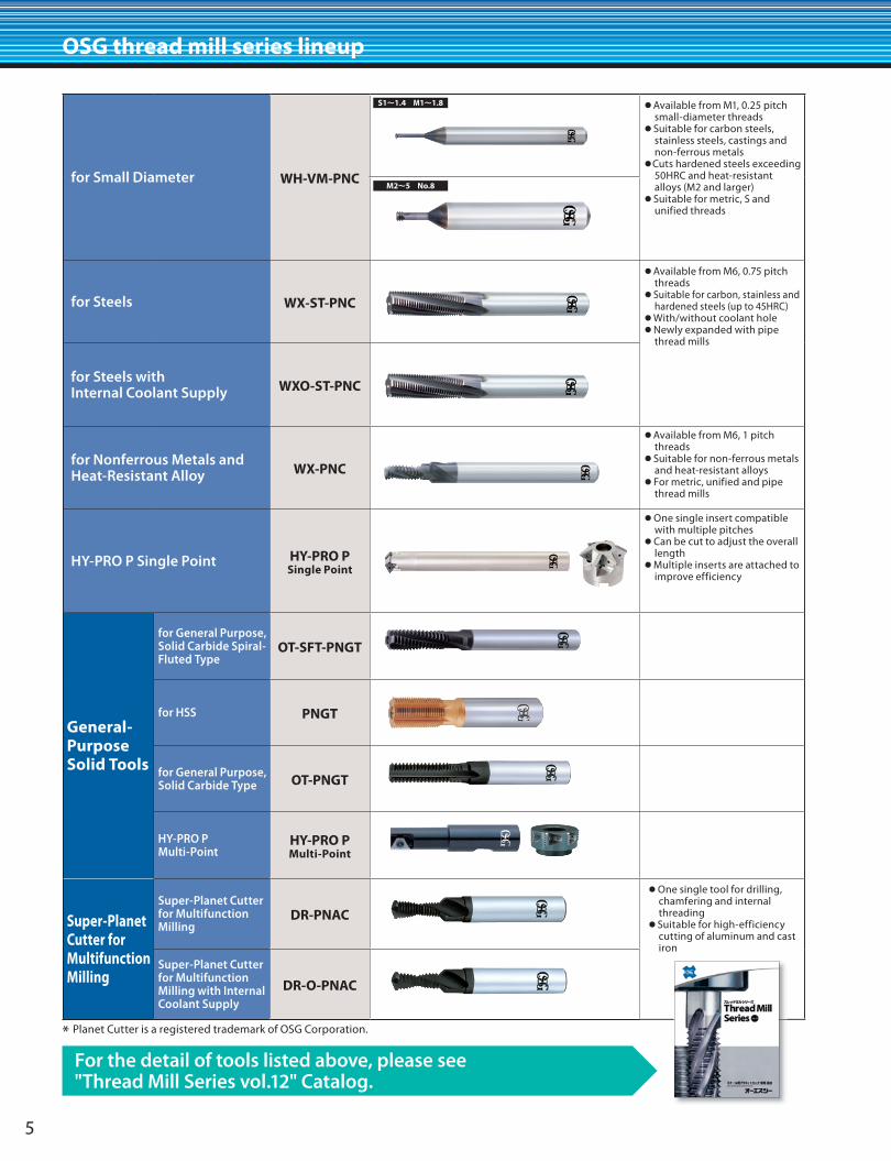
OSG thread mill series lineup
For the detail of tools listed above, please see "Thread Mill Series vol.12" Catalog.
for Small Diameter WH-VM-PNC
●Available from M1, 0.25 pitch small-diameter threads
●Suitable for carbon steels, stainless steels, castings and non-ferrous metals
●Cuts hardened steels exceeding 50HRC and heat-resistant alloys (M2 and larger)
●Suitable for metric, S and unified threads
for Steels WX-ST-PNC
●Available from M6, 0.75 pitch threads
●Suitable for carbon, stainless and hardened steels (up to 45HRC)
●With/without coolant hole●Newly expanded with pipe
thread mills
for Steels with Internal Coolant Supply WXO-ST-PNC
for Nonferrous Metals and Heat-Resistant Alloy WX-PNC
●Available from M6, 1 pitch threads
●Suitable for non-ferrous metals and heat-resistant alloys
●For metric, unified and pipe thread mills
HY-PRO P Single Point HY-PRO PSingle Point
●One single insert compatible with multiple pitches
●Can be cut to adjust the overall length
●Multiple inserts are attached to improve efficiency
General-Purpose Solid Tools
for General Purpose, Solid Carbide Spiral-Fluted Type
OT-SFT-PNGT
for HSS PNGT
for General Purpose, Solid Carbide Type OT-PNGT
HY-PRO P Multi-Point
HY-PRO PMulti-Point
Super-Planet Cutter for Multifunction Milling
Super-Planet Cutter for Multifunction Milling
DR-PNAC
●One single tool for drilling, chamfering and internal threading
●Suitable for high-efficiency cutting of aluminum and cast iron
Super-Planet Cutter for Multifunction Milling with Internal Coolant Supply
DR-O-PNAC
* Planet Cutter is a registered trademark of OSG Corporation.
M2~5 No.8
S1~1.4 M1~1.8

6
Limit gauges for screw threads are graded in the same manner as screws. Screw threads are inspected according to two limits defined by GO and NO GO gauges. The Previous JIS gauge system provides two categories of NO GO gauges depending on the purpose of usage: machining and inspection. This classification is not used in the ISO system. Screw threads pass the inspection if the GO gauge, when screwed by hand without using excess force on the thread under test for the specified engagement length, goes over the entire thread length, and if the NO GO gauge, when screwed by hand without using excess force, enter on both sides by not more than two turns of thread (not more than three turns of thread in ANSI).
Gauges for taper pipe threads are used to inspect taper pipe threads and parallel pipe internal threads that f it taper threads. A taper thread plug gauge and a taper thread ring gauge form a pair of gauges for taper pipe threads. To inspect the manufacturing tolerance for an internal taper thread or external taper thread, the notch in the large end of a taper thread plug gauge or the small end of a taper thread ring gauge is referred to. When a taper thread plug or ring gauge is screwed up into or on an internal or external taper thread by hand, the pipe or pipe fitting passes the inspection if its end is within the range defined by the notch. The JIS standard for taper pipe threads was revised in 1982. Its main text sets out the content of ISO 7/1, using thread symbols "R," "Rc" and "Rp." Symbols "PT" and "PS" used in the previous JIS edition are specified in the Appendix to the standard. To inspect pipe threads specified in the revised JIS, gauges that bear the new thread symbols should be used.
In September 1966, the JIS standard for parallel pipe threads was revised to incorporate ISO standards. As a result, JIS B 0202 (principally addressing mechanical joints) was added to the existing JIS B 0203 (principally addressing sealability). The revision involved radical amendments to the specifications for screw thread gauges. The JIS B 0253 (PS) for taper threads focused on sealability as a principal purpose. Since sealability is concerned with the combination of an external taper thread and a parallel internal thread, screw thread plug gauges survived while screw thread ring gauges were discontinued. Meanwhile, JIS B 2054 (PF) was established principally for mechanical joints. Subsequently, JIS B 0202 (Parallel pipe threads) was revised in 1982. Its main text sets out the content of ISO 228/1, using the thread symbol "G," while "PF" used in the previous JIS edition is specified in the Appendix. Furthermore, the main text of JIS B 0203 (Taper pipe threads) also sets out the content of ISO 7/1, using thread symbols "R," "Rc" and "Rp." Symbols "PT" and "PS" used in the previous JIS edition are specified in the Appendix to the standard.
Gauges for ANSI taper pipe threads (NPT) are used to inspect taper pipe threads (NPT) in general sealable parts. Various gauge specifications are in use for NPT gauges, some of which have notches, while others do not. Commonly used thread plug and ring gauges are provided with three-step notches (L1). If the inspected taper thread conforms to the standard dimensions, the pipe end stops at the BASIC position, which is the middle notch on the gauge. The other two notches indicate the maximum and minimum allowed dimensions.
Gauges for ANSI taper pipe threads (NPTF) are intended for threads used to join fuel or oil pipes in ships, automobiles, aircraft and etc. These threads are designed to achieve dry seal joints without using a sealing material. L1 plug and L1 ring are used to inspect the hand-tight length (L1) of external and internal threads. L3 plug and L2 ring are used to check the wrench-t ight length (L3 and L2-L1) of external and internal threads. When the positional relationship of the notches of two gauges, L1 and L3 plugs, or L1 and L2 rings, is not more than a half turn, the degree of taper of the product is guaranteed.* We offer L1 gauges as standard stocked items. L2 and L3 gauges are made to order.
for Internal thread for Internal thread
GO sideGO side
GO sideGO side
NO GO sideNO GO side
NO GO sideNO GO side
for External thread for External thread
LG Limit gauges for screw threads
TG(R·PT)
Gauges for taper pipe threads
TG(NPT)
Gauges for ANSI taper pipe threads
TG(NPTF)
Gauges for ANSI taper pipe threads
LG(G·PF·PS)
Limit gauges for parallel pipe threads
OSG offers a comprehensive line of precision measurement tools for the gauging of threads.
For the details of gauges listed above, please see "Gauges Stock List 2014.07~ " .

東部営業部〒143-0025 東京都大田区南馬込3-25-4 ☎(03)5709-4501 FAX(03)5709-4515
中部営業部〒465-0058 愛知県名古屋市名東区貴船1-9 ☎(052)703-6131 FAX(052)703-7775
西部営業部〒550-0013 大阪府大阪市西区新町2-18-2 ☎(06)6538-3880 FAX(06)6538-3879
〈工具の技術的なご相談は…〉よ い 工 具 は 一 番
コミュニケーションE-mailコミュニケーションFAX
コミュニケーションダイヤル
OSG E-mail倶楽部《無料メールマガジン》OSG HP《最新情報》
9:00~12:00/13:00~19:00 土日祝日を除く
0533-82-1134 [email protected]
https://www.osg.co.jp/support/club/http://www.osg.co.jp/
仙 台 ☎ (022)390-9701郡 山 ☎ (024)991-7485新 潟 ☎ (025)286-9503上 田 ☎ (0268)28-7381諏 訪 ☎ (0266)58-0152両 毛 ☎ (0270)40-5855宇都宮 ☎ (028)651-2720八王子 ☎ (042)645-5406茨 城 ☎ (029)354-7017東 京 ☎ (03)5709-4501厚 木 ☎ (046)296-1380
静 岡 ☎ (054)283-6651浜 松 ☎ (053)461-1121豊 川 ☎ (0533)92-1501安 城 ☎ (0566)77-2366名古屋 ☎ (052)703-6131岐 阜 ☎ (058)259-6055三 重 ☎ (0594)26-0416金 沢 ☎ (076)268-0830京 滋 ☎ (077)553-2012大 阪 ☎ (06)6747-7041明 石 ☎ (078)927-8212
岡 山 ☎ (086)241-0411四 国 ☎ (087)868-4003広 島 ☎ (082)507-1227九 州 ☎ (092)504-1211北九州 ☎ (093)435-3655熊 本 ☎ (096)386-5120東部GST ☎ (03)5709-4501中部GST ☎ (052)703-6131西部GST ☎ (06)6538-3880
〒442-8543 愛知県豊川市本野ヶ原3-22☎ (0533)82-1111 FAX (0533)82-1131
3-22 Honnogahara, Toyokawa, Aichi, 442-8543, JAPANTEL. +81-533-82-1118 FAX. +81-533-82-1136
●工具を使用する時は、破損する危険があるので、 必ずカバー・保護メガネ・安全靴等を使用して下さい。●切れ刃は素手でさわらないで下さい。●切りくずは素手でさわらないで下さい。
●工具の切れ味が悪くなったら使用を中止して下さい。●異常音・異常振動が発生したら、直ちに使用を中止して下さい。●工具には手を加えないで下さい。●加工前に工具の寸法確認を行って下さい。
●Use safety cover, safety glasses and safety shoes during operation.●Do not touch cutting edges with bare hands.●Do not touch cutting chips with bare hands. Chips will be hot after cutting.●Stop cutting when the tool becomes dull.
●Stop cutting operation immediately if you hear any strange cutting sounds.
●Do not modify tools.●Please use correct tools for the operation.Check
dimensions to ensure proper selection.
Safe use of cutting tools
〈その他のお問い合わせは…〉E-mail:[email protected]
◆製品については、常に研究・改良を行っておりますので、予告なく本カタログ掲載仕様を変更する場合があります。◆Tool specifications are subject to change without notice.
OSG代理店
※本書掲載内容の無断転載・複製を禁じます。※ All rights reserved. ©2015 OSG Corporation.
(DN)16.01