dg 415-1 readiness centers design guide · this readiness centers design guide (dg 415-1) was...
TRANSCRIPT

DG 415-1 01 JUNE 2011

DG 415-1 01 JUNE 2011
i
FOREWORD
This Readiness Centers Design Guide (DG 415-1) was published by the National Guard Bureau, Army Installations Division (ARNG-ILI). DG 415-1 applies to all projects for new construction (including additions) as well as alterations to and rehabilitation and conversion of existing facilities. It is intended to assist the States, Territories, the District of Columbia and design professionals in gaining an understanding of the functions and the unique environmental considerations to address in the construction documents development. This design guide does not contain criteria but refers readers to sources of criteria in other publications that relate directly to the specific technical design requirements. This Readiness Centers Design Guide should be used in conjunction with the General Facilities Information Design Guide (DG 415-5) to develop the final project design. Distribution is limited. However, authorized users of the NGB Guard Knowledge Online (GKO), can obtain an electronic copy at https://gkoportal.ngb.army.mil/sites/ARI-HQ/default.aspx, Design, Guide Library site. All users are encouraged to submit comments and suggestions to improve this document by completing DA Form 2028, “Recommended Changes to Publications and Blank Forms,” and sending it directly to:
National Guard Bureau Installations Division
ARNG Readiness Center 111 South George Mason Drive
Arlington, VA 22204-1382

DG 415-1 01 JUNE 20011
CONTENTS
ii
Page
CHAPTER 1 GENERAL INFORMATION ........................................................................ 1 1-1 PURPOSE: PERFORMANCE DESIGN GUIDE ....................................... 1 1-2 FUNCTIONS AND OPERATIONS OF READINESS CENTERS ............... 1 1-2.1 Primary Function ........................................................................................ 2 1-2.2 Secondary Function ................................................................................... 2 1-2.3 Tertiary Functions ...................................................................................... 2 1-2.4 Part-Time Functions .................................................................................. 2 1-2.4.1 Part-Time Unit Training Assemblies .......................................................... 2 1-2.4.2 Part-Time Meetings ................................................................................... 2 1-2.4.3 Part-Time Special Training Classes........................................................... 2 CHAPTER 2 READINESS CENTER FUNCTIONAL DESIGN GUIDANCE .................... 3 2-1 ARRANGEMENT AND ACCOMMODATION
OF BASIC SITE COMPONENTS .............................................................. 3 2-2 FUNDAMENTAL PLANNING FOR THE BASIC READINESS CENTER ... 3 2-2.1 Basic Components ..................................................................................... 3 2-2.2 Varying Operational Requirements ............................................................ 4 2-2.3 Accommodating Incompatible Functions ................................................... 4 2-2.4 Plan for Potential Growth ........................................................................... 4 2-3 DESIGN GUIDANCE FOR PROGRAM SPACES ...................................... 4 2-3.1 Assembly Hall ............................................................................................ 4 2-3.1.1 Flexibility of Use ......................................................................................... 5 2-3.1.2 Placement within the Facility...................................................................... 5 2-3.1.3 Support for Presentations .......................................................................... 5 2-3.1.4 Direct Vehicle Access ................................................................................ 5 2-3.1.5 Air Conditioning Policy .............................................................................. 5 2-3.2 Classrooms ................................................................................................ 5 2-3.2.1 Classrooms/Meeting Rooms ...................................................................... 6 2-3.2.2 Library/Classroom ...................................................................................... 6 2-3.2.3 Learning Center ......................................................................................... 6 2-3.2.4 Distance Learning Center .......................................................................... 6 2-3.2.5 Audio/Visual and Training Aid Storage ...................................................... 6 2-3.3 Indoor Firing Range ................................................................................... 7 2-3.3.1 Design Guidance ....................................................................................... 7 2-3.3.2 Independent Access .................................................................................. 7 2-3.3.3 Ventilation Testing ..................................................................................... 7 2-3.3.4 Exterior Space Requirements .................................................................... 8 2-3.3.5 Break Room and Vending Area ................................................................. 8 2-3.3.6 Toilets and Showers .................................................................................. 8 2-3.3.7 Table/Chair Storage ................................................................................... 8 2-3.3.8 Physical Fitness Area ................................................................................ 8 2-3.3.9 Nursing Mothers Room ............................................................................. 8

DG 415-1 01 JUNE 2011
iii
2-4 EXCLUSIVE USE AREAS ......................................................................... 8 2-4.1 Unit Administration ..................................................................................... 8 2-4.2 Heated and Ventilated Unit Storage .......................................................... 9 2-4.3 Vault ..................................................................................................... 9 2-4.4 Locker Rooms ............................................................................................ 9 2-4.5 Recruiting/Retention Office ........................................................................ 9 2-4.6 Family Readiness Office ............................................................................ 9 2-4.7 RAPIDS Office ........................................................................................... 9 2-4.8 Communications Security Areas ................................................................ 9 2-4.8.1 Storage Areas .......................................................................................... 10 2-4.8.2 Training Device/Simulation Center .......................................................... 10 2-4.8.3 Secret Internet Protocol Router Network Room ....................................... 10 2-4.9 Maintenance/Training Area ...................................................................... 10 2-4.9.1 Supervisor’s Office ................................................................................... 10 2-4.9.2 Supply and Tool Rooms .......................................................................... 10 2-4.9.3 Battery Room ........................................................................................... 10 2-4.9.4 Bulk POL Storage .................................................................................... 10 2-4.9.5 Inspection and Library Area ..................................................................... 11 2-4.9.6 Maintenance Training Work Bays ............................................................ 11 2-4.10 Special-Purpose Areas ............................................................................ 11 2-4.10.1 Headquarters Functions .......................................................................... 11 2-4.10.2 Army Advisor’s Office .............................................................................. 11 2-4.10.3 Band Facilities ......................................................................................... 11 2-5 BASIC FACILITY FUNCTIONS ............................................................... 11 2-5.1 Facility Maintenance Storage................................................................... 11 2-5.2 Mechanical, Electrical, and Telecommunications Rooms ........................ 11 2-5.3 Facility Maintenance and Custodial Area ................................................. 11 2-5.4 Flammable Materials Storage Building .................................................... 12 2-5.5 Controlled Waste Handling ...................................................................... 12 2-5.6 Wash Platforms for Vehicles and Equipment .......................................... 12 2-5.7 Fuel Storage and Dispensing System ...................................................... 12 2-5.8 Exterior Lubrication and Inspection Rack ................................................ 12 2-5.9 Recycling Area ......................................................................................... 12
CHAPTER 3 FOOD SERVICE AREA ........................................................................... 13 3-1 Food Service Area ................................................................................... 13 3-1.1 Kitchen ..................................................................................................... 13 3-1.2 Food Storage Area .................................................................................. 13 3-1.3 Food Preparation Area ............................................................................ 13 3-1.4 Serving Area ............................................................................................ 13 3-1.5 SCULLERY .............................................................................................. 14 3-2 KITCHEN LAYOUT AND EQUIPMENT LIST .......................................... 14
CHAPTER 4 UNIQUE ANTITERRORISM FORCE PROTECTION REQUIREMENTS . 17
DG 415-1 01 JUNE 2011
iv
CHAPTER 5 UNIQUE ARCHITECTURAL AND ENGINEERING SUBMISSION REQUIREMENTS CHECKLIST ............................................................... 18
CHAPTER 6 UNIQUE ARCHITECTURAL AND ENGINEERING DESIGN DIRECTIVE
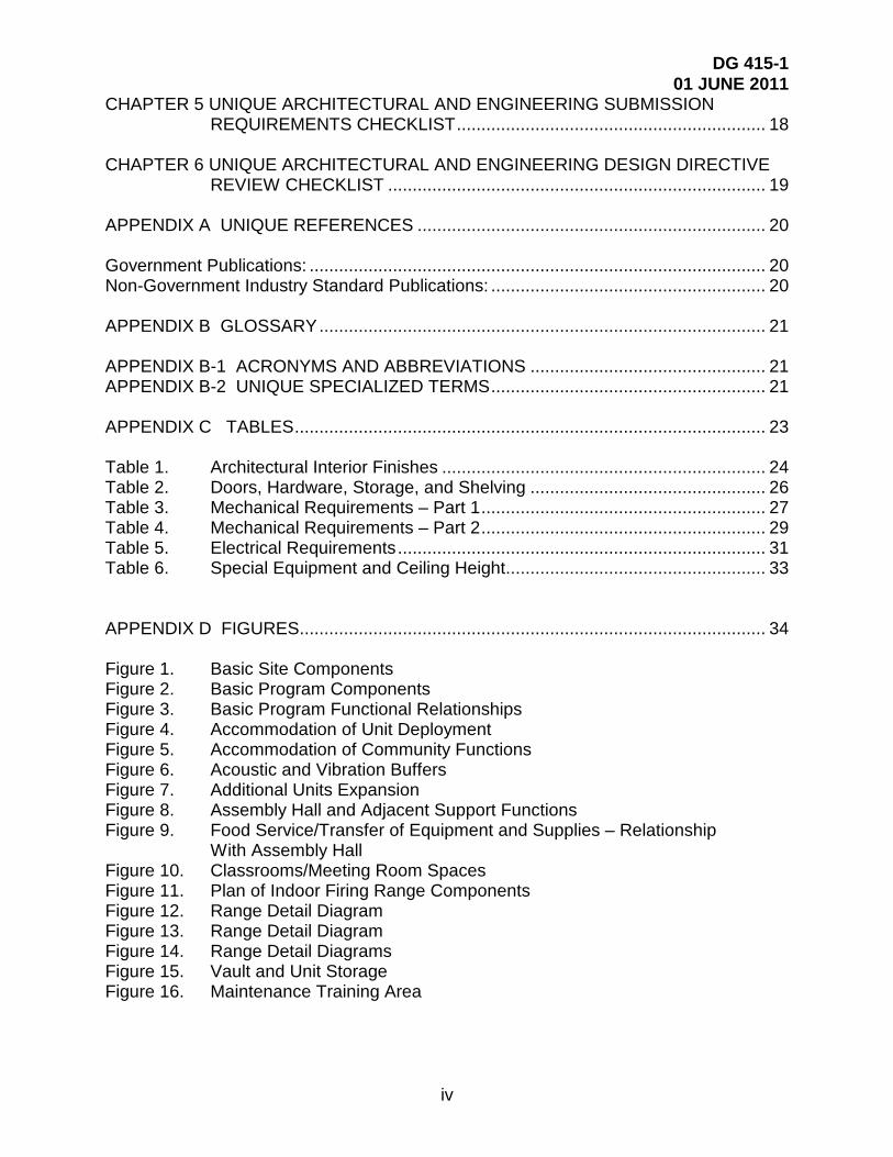
REVIEW CHECKLIST ............................................................................. 19 APPENDIX A UNIQUE REFERENCES ....................................................................... 20 Government Publications: ............................................................................................. 20 Non-Government Industry Standard Publications: ........................................................ 20 APPENDIX B GLOSSARY ........................................................................................... 21 APPENDIX B-1 ACRONYMS AND ABBREVIATIONS ................................................ 21 APPENDIX B-2 UNIQUE SPECIALIZED TERMS ........................................................ 21 APPENDIX C TABLES ................................................................................................ 23 Table 1. Architectural Interior Finishes .................................................................. 24 Table 2. Doors, Hardware, Storage, and Shelving ................................................ 26 Table 3. Mechanical Requirements – Part 1 .......................................................... 27 Table 4. Mechanical Requirements – Part 2 .......................................................... 29 Table 5. Electrical Requirements ........................................................................... 31 Table 6. Special Equipment and Ceiling Height ..................................................... 33 APPENDIX D FIGURES ............................................................................................... 34 Figure 1. Basic Site Components Figure 2. Basic Program Components Figure 3. Basic Program Functional Relationships Figure 4. Accommodation of Unit Deployment Figure 5. Accommodation of Community Functions Figure 6. Acoustic and Vibration Buffers Figure 7. Additional Units Expansion Figure 8. Assembly Hall and Adjacent Support Functions Figure 9. Food Service/Transfer of Equipment and Supplies – Relationship
With Assembly Hall Figure 10. Classrooms/Meeting Room Spaces Figure 11. Plan of Indoor Firing Range Components Figure 12. Range Detail Diagram Figure 13. Range Detail Diagram Figure 14. Range Detail Diagrams Figure 15. Vault and Unit Storage Figure 16. Maintenance Training Area

DG 415-1 01 JUNE 2011
1
CHAPTER 1
GENERAL INFORMATION
1-1 PURPOSE: PERFORMANCE DESIGN GUIDE This Readiness Centers Design Guide (DG 415-1) contains design and functional planning guidance information for the design architect-engineer (A-E) to use in developing the design and the construction contract documents for Army National Guard (ARNG) readiness centers projects that qualify for support, totally or in part, from Federal funds. Readiness centers projects include Readiness Centers (Armory), Civil Support Team/Weapons of Mass Destruction (CST-WMD)-Ready Buildings, and joint-use Armed Forces Reserve Centers (AFRC). This design guide is applicable to all construction projects, including new construction, major alterations, rehabilitation and adaptive reuse of existing facilities. All ARNG facilities must be designed and constructed using the principles and practices of sustainable design and development using the latest version of the U.S. Green Building Council Leadership in Environmental and Energy Design (LEED) Green Building Rating System to achieve a “Silver” rating.
DG 415-1 addresses the unique functional design requirements for specific types of buildings. It should be used in conjunction with the General Facilities Information Design Guide (DG 415-5), which contains technical design guidance common to all Army National Guard building types. Together, the two design guides provide the functional performance information necessary to assist in developing the facility design.
To aid the reader in using this design guide, the following are included:
▪ Appendix A, Unique References, lists reference documents that pertain specifically to this building type; other references cited in this design guide are included in the References in DG 415-5.
▪ Appendix B, Glossary, defines the acronyms and abbreviations used in this design guide as well as specialized terms that are unique to this design guide.
▪ Appendix C contains several tables of requirements.
▪ Appendix D contains the figures that illustrate the explanations in the text.
1-2 FUNCTIONS AND OPERATIONS OF READINESS CENTERS A readiness center is defined as a facility that houses one or more units of the State Army National Guard.

DG 415-1 01 JUNE 2011
2
1-2.1 Primary Function
Readiness centers provide administrative, training, and material storage areas for the assigned military unit(s). Generally, full-time operations are limited to those personnel required to provide continuous support in unit administration plus preparation and planning for unit training, supply, administration, and recruiting. The administrative sector of the building should be designed to allow independent operational shutdown when other functions remain active.
1-2.2 Secondary Function
Readiness centers are also utilized to support State functions such as disaster relief and policing actions in case of civil disturbance.
1-2.3 Tertiary Functions
In addition, readiness centers provide for military and public social functions (the latter generally on a rental basis), and shelters during emergency or natural disasters. Public access to functional spaces is normally limited to the assembly hall, indoor firing range (used by authorized local organizations), lobby, toilet, classroom, and food preparation and scullery areas. The functional layout should appropriately compartmentalize all areas to support these uses.
1-2.4 Part-Time Functions
Part-time functions are unit training assemblies, meetings, and special training classes, described below.
1-2.4.1 Part-Time Unit Training Assemblies Unit training assemblies are normally conducted on one weekend per month per unit. Several units may train on the same weekend. The number of weekends on which these assemblies take place depends on individual unit situations and scheduling; however, common practice is to alternate weekends. All unit personnel, both part time and full time, normally attend such assemblies.
1-2.4.2 Part-Time Meetings Administration and training meetings may be conducted on one or more nights per month.
1-2.4.3 Part-Time Special Training Classes Classes may be conducted at night during the week or on a weekend, as circumstances dictate.

DG 415-1 01 JUNE 2011
3
CHAPTER 2
READINESS CENTER FUNCTIONAL DESIGN GUIDANCE
2-1 ARRANGEMENT AND ACCOMMODATION OF BASIC SITE COMPONENTS The primary purpose of every readiness center is to provide an environment for administering the assigned unit or units, training for their mobilization mission, and storing the immediate equipment that they would take to their mobilization station. In addition to the functional space that is authorized every unit for this purpose, space for certain special units and activities not present at every readiness center may be authorized in accordance with guidance in NG PAM 415-12. For this reason, a careful study of the space authorizations in the DD Form 1390/91 approved program documents is essential to understanding how best to arrange the various functional groups in any given case. A further complication arises from the fact that certain functional spaces are set aside as common-use areas for all personnel in multi-unit readiness centers, whereas other functional areas are dedicated to sole use by a single unit, even at multi-unit readiness centers.
The main readiness center building should be located to maximize its visual presence in the community and to facilitate accessibility from the public thoroughfare, subject to any constraints imposed by antiterrorism/force protection (UFC 4-010-01/02), soil conditions and topography of the site. The military vehicle storage compound and supporting structures, such as the unheated unit storage building, should be located at the rear to minimize visual impact. Functional areas within the complex that have the greatest potential for expansion shall be placed with adequate site space to grow. Future expansion of the building and parking should be shown on the plans and considered in the layout to eliminate the need to remove and relocate paved areas and utilities. (See Figure 1, Basic Site Components.).
2-2 FUNDAMENTAL PLANNING FOR THE BASIC READINESS CENTER To provide the design A-E with an understanding of important planning relationships within a readiness center, several diagrams in Appendix D address the fundamental activities and functional dependencies that have a significant impact on the building design. In addition, Table 1 in Appendix C addresses proximity requirements between each program function listed in NG PAM 415-12, Chapter 2, Readiness Centers.
2-2.1 Basic Components
Basic program components, which may consist of several individual dependent spaces and their fundamental interrelationships, are illustrated in Appendix D, Figures 1- 5.
All the basic functional relationships for individual program spaces to support one unit accommodating 250 to 300 troops are shown in Figure 3. This arrangement demonstrates one of many configurations possible to satisfy basic requirements. It is

DG 415-1 01 JUNE 2011
4
provided to illustrate the many important interdependencies between the program spaces within a typical Readiness Center. One of the main planning goals is to maximize the flexibility of use of the assembly hall.
2-2.2 Varying Operational Requirements
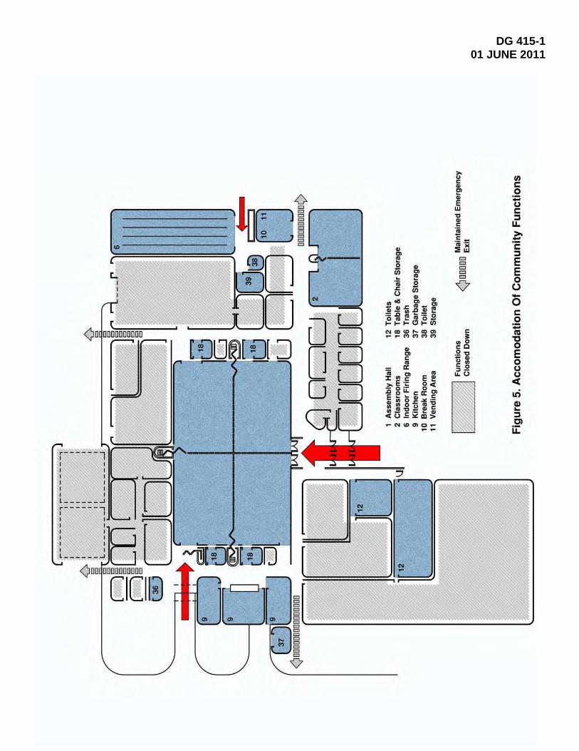
Figure 4, Accommodation of Unit Deployment, in Appendix D illustrates those essential functions that actively support unit deployment and those that can be locked down. Figure 5, Accommodation of Community Functions, in Appendix D indicates those functions supporting a typical community activity. When allowing access to the public, some of the challenges of the facility design are maintaining the security of unit and basic National Guard functions and providing emergency egress for large groups. Another very important element of the design is effective and efficient zoning of internal environmental systems to accommodate flexibility of use.
2-2.3 Accommodating Incompatible Functions
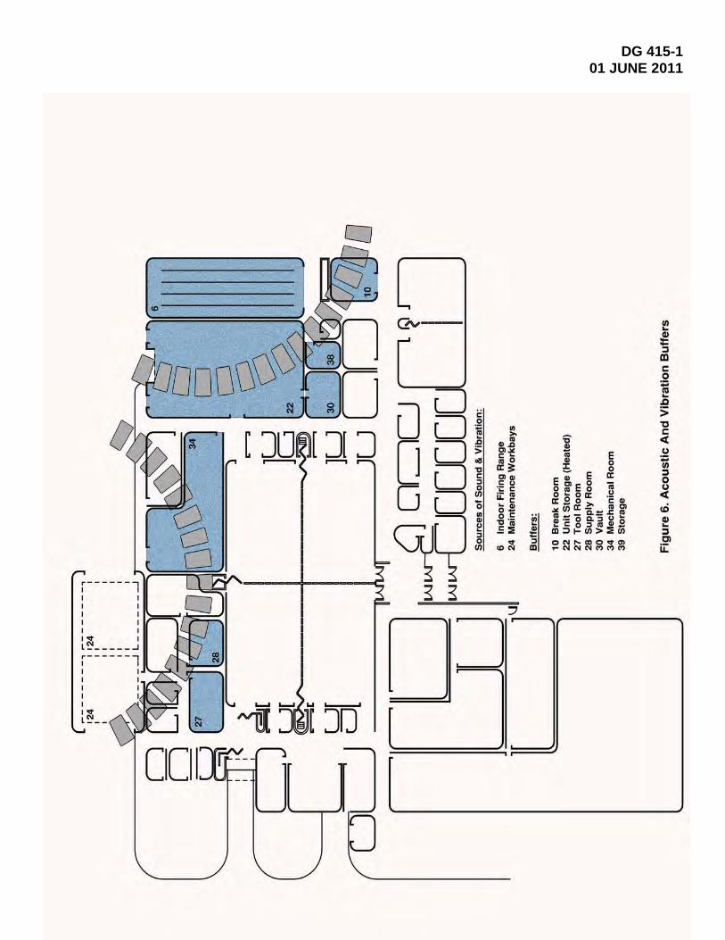
Two functions that are included in a typical readiness center but are incompatible with most of the other functions because of noise and vibration are the maintenance area and the indoor firing range. Figure 6, Acoustic and Vibration Buffers, in Appendix D, illustrates one solution that provides neutral spaces between the noise- and vibration-sensitive areas of the building. In this case, it is suggested to use storage components and the break room to provide the buffer.
2-2.4 Plan for Potential Growth
In the future, it is possible for additional units to be housed at the readiness center. Therefore, the initial design should provide for orderly expansion related to both the facility site plan and the arrangement of functions within the building. Figure 7, Additional Units Expansion, in Appendix D, shows the incremental growth to accommodate requirements for new units assigned to the readiness center, which include storage of equipment and supplies plus administrative support. With the incorporation of additional units at a facility, incremental growth of the major readiness center support program spaces should also be expected to occur.
2-3 DESIGN GUIDANCE FOR PROGRAM SPACES 2-3.1 Assembly Hall The primary function of the assembly hall is to provide space for troop formations, inspections, dining, and large group assemblies for training. The assembly hall also serves the neighboring community as a place of public assembly and as a refuge in case of natural disaster. The assembly hall must accommodate direct access for loading and off-loading supplies and equipment from unit vehicles. Therefore, a loading dock is required adjacent to this space. The food service must also be adjacent to this space because food service will be provided for both the unit and local civic and private functions using the assembly hall. Heated unit storage must be in very close proximity to the assembly hall to allow efficient organization of equipment for deployment.

DG 415-1 01 JUNE 2011
5
2-3.1.1 Flexibility of Use Flexibility is the key design issue related to the assembly hall. To accommodate the various uses planned for this space, the most versatile approach is division by flexible partitions that are appropriately detailed at the top and bottom plus panel composition to provide maximum acoustic separation. Acoustical treatment should be also provided above the ceiling to the underside of the roof deck or at the floor under folding partitions to attain a proper sound transmission coefficient (STC) rating within each subdivided space.
Multiple entry points should be aligned with each space compartment when all flexible partitions are fully deployed. This arrangement allows most of the support storage to be located outside of the assembly hall and the stored materials to be easily taken around the perimeter to any one of the compartmentalized areas. (See Figure 8, Assembly Hall and Adjacent Support Functions, in Appendix D.)
2-3.1.2 Placement within the Facility Placement of the assembly hall should allow the public direct access off the main lobby. Important support functions that should be located in close proximity include storage for chairs, tables, and audio/visual (AV) equipment plus toilet facilities of adequate size to support the largest group activities anticipated. In addition, food preparation and serving facilities should be located immediately adjacent to the assembly hall. The feasibility of locating the food serving area off the corridor adjacent to the assembly hall, with adequate queuing space, should be considered because of the acoustical isolation provided from the activities in the hall space. (See Figure 9, Food Service/Transfer of Equipment in Relationship to Assembly Hall, in Appendix D.)
2-3.1.3 Support for Presentations An adequate power supply for all anticipated functions is critical to flexible use. Connections to the Internet and other data systems should be provided at multiple locations and aligned with the maximum subdivision arrangements. A ceiling-mounted projection system may be beneficial for large group meetings.
2-3.1.4 Direct Vehicle Access The assembly hall should be located for direct access to unit support vehicles that carry supplies and equipment. This can be accomplished by providing a loading dock with overhead coiling doors adjacent to the perimeter of the space. (The vehicles do not come into the assembly hall.) The loading dock should also accommodate food service supplies. See Figure 9, Food Service/Transfer of Equipment in Relationship with Assembly Hall, in Appendix D.
2-3.1.5 Air Conditioning Policy The Assembly Hall maybe environmental controlled with a mechanical air conditioning system to maintain 78 degrees F and 50% RH. The space must be heated and ventilated by a central station air handling unit (AHU) with an 85% efficiency filter bank base on ASHRAE Standard 52.1-1992 Atmospheric Dust-Spot Efficiency rating.
2-3.2 Classrooms The classroom area is subdivided as described below.

DG 415-1 01 JUNE 2011
6
2-3.2.1 Classrooms/Meeting Rooms Classrooms are used for instructional training of unit personnel and for unit meetings. They may also be used by the public. The classrooms/meeting rooms and their related support components are illustrated in Figure 10, Classrooms/Meeting Room Spaces, in Appendix D. If classrooms are to be provided independently of the assembly hall, the following applies:
▪ The space authorized in the approved program documents should be used for the design.
▪ Classrooms that are 900 ft2 or larger may be provided with an accordion or folding partition to divide the classroom area into two smaller rooms.
▪ Acoustical treatment should be provided above the ceiling to the underside of the roof deck or at the floor under the acoustically insulated folding partition(s) to attain an STC of 40.
▪ Lighting controls for each individual classroom and subdivision should be located at a point convenient to the speaker and at the door.
▪ Fixed speaker’s platforms, chalkboards or marker boards with map rails, and electrical outlets for AV equipment should be provided.
▪ A portion of the authorized classroom space may be designed as an auditorium with an inclined floor and installed seats plus a raised platform at the front.
2-3.2.2 Library/Classroom The library/classroom accommodates a reading area with training publications and other reading material. This space may be combined with the learning center. A chalkboard with map rails as well as electrical convenience outlets should be provided.
2-3.2.3 Learning Center The learning center should be adjacent to, or combined with, the library/classroom. This space should be equipped with individual pre-wired study carrels for military occupational skills (MOS) training. The learning center should have built-in shelving or racks and a chalkboard as well as electrical outlets to accommodate AV equipment in the study carrels.
2-3.2.4 Distance Learning Center The distance learning center provides space for delivery of remote training and educational resources. It requires accommodation of voice and data links.
2-3.2.5 Audio/Visual and Training Aid Storage Storage rooms for AV equipment and training aids should be adjacent to, and preferably have direct access to, the library/classroom and the learning center. The storage rooms should be designed to maximize wall space. Each room should have built-in shelving or racks, or both.
DG 415-1 01 JUNE 2011
7
2-3.3 Indoor Firing Range The indoor firing range is used for marksmanship practice and qualification. Spatial requirements include a storage room and a small toilet. (See Figure 11, Plan of Indoor Firing Range Components, in Appendix D.)
2-3.3.1 Design Guidance The environment of the actual range area is unique both in the construction materials and the ventilation requirements. Materials used in the exposed construction, including baffled elements, must be able to deflect projectiles toward the target with no possibility of ricochet in the shooter’s direction. The materials must also be substantial enough to prevent any rounds fired from any location or direction from escaping the immediate environment.
Horizontal safety ceilings, ceiling baffles, deflectors, and shields (sheathing) provide safe ballistic conditions above the firing line and down range of the shooters. All non-bullet-proof walls and ceilings down range must be either sheathed with round-absorbing material or baffled to divert stray bullets back into the range. Ceiling or sidewall-supported deflection baffles should be located close to the bullet trap to redirect stray rounds to the primary impact plates of the bullet trap.
Bullet traps and baffles must extend the full width and height of the back wall of the range and have a profile that directs all bullets into the deceleration chamber of the bullet trap.
Air ventilation pressure in the range area must always be negative with regard to the direction of the bullet trap to avoid contamination by bullet backspatter.
Supply air should be filtered at 35% efficiency and 60 degrees F minimum through a perforated wall at the face of the air plenum behind the firing line. Exhaust air final filter be HEPA Type w/85% efficiency pre-filter or as required by the U.S. Environmental Protection Agency.
For the design criteria, refer to UFC 4-160-01, AR 210–21, ER 210-3-2, and the American Conference of Governmental Industrial Hygienists (ACGIH) Industrial Ventilation Manual and U S Navy Environmental Health Center TM 6290.99-10. (See Range Detail Diagrams, in Appendix D, Figures 11, 12, 13 & 14.)
2-3.3.2 Independent Access A means of access that is independent from the remainder of the facility functions should be provided to allow community shooting groups and law enforcement agencies to utilize the range.
2-3.3.3 Ventilation Testing The contract documents should stipulate that the construction contractor is to hire a qualified independent testing firm to evaluate the ventilation system in the completed range. The evaluation should ensure that the air flow at the firing line is uniformly distributed over the room cross section to achieve 75 FPM minimum velocity with laminar flow down range.

DG 415-1 01 JUNE 2011
8
2-3.4 Exterior Space Requirements The facility should have a garbage can wash area that includes a source of hot and cold water and a drain with a grease separator. Garbage can storage should be adjacent to the building and screened from sight.
2-3.5 Break Room and Vending Area For the size requirements for the break room and vending area, refer to NG PAM 415-12, Chapter 2; and for design guidance, refer to the discussion of common facility functional areas in DG 415-5, Chapter 5, Common Functional Planning and Building Design Guidelines.
2-3.6 Toilets and Showers The majority of the toilets should be concentrated with, but separated from, the shower facilities that accommodate cleanup after unit training activities. Toilets should also be easily accessible to those attending public functions. Refer to the general design guidance included in DG 415-5, Chapter 5. For size requirements, refer to NG PAM 415-12, Chapter 2.
2-3.7 Table/Chair Storage Areas for table and chair storage should be located on the perimeter of the assembly hall. They should be accessible from both the assembly hall and the corridor to promote optimum flexibility in the use and configuration of the assembly hall space. (See Figure 8, Assembly Hall and Adjacent Support Functions, in Appendix D.)
2-3.8 Physical Fitness Area For design guidance regarding the physical fitness area, refer to DG 415-5, Chapter 5; and for size requirements, refer to NG PAM 415-12, Chapter 2.
2-3.9 Nursing Mothers Room Any ARNG facility that include an Administrative Area is authorized a net area of 80-square feet enclosed room with complete environmental systems and one cabinet/counter mounted 16”x16” sink to support this effort.
2-4 EXCLUSIVE USE AREAS
2-4.1 Unit Administration The allocated net square footage for each administrative component is determined from NG PAM 415-12 and specifically indicated in the approved program documents for the project. The actual number of administrative personnel and their office or workstation requirements as well as assigned equipment such as file cabinets, desks, chairs, and personal computers should be determined at the pre-design conference. At a minimum, the unit commander, executive officer, and a senior non-commissioned officer should have private offices.
The layout of the unit administrative space must take into account the need to locate full-time administrative personnel adjacent to the main entrance and lobby for visitor control. A viewing window should be provided in an adjacent lobby so that the entrance can be kept under observation from both a standing and seated position at the reception area. Office furniture consisting of modularly dimensioned components
DG 415-1 01 JUNE 2011
9
should be a strong consideration when laying out the open administrative areas because modular furniture allows flexibility for rearrangement in the future.
2-4.2 Heated Unit Storage Heated and ventilated unit storage is authorized for each assigned unit to provide a secure area for storing, issuing, and returning organizational equipment and clothing. The H/V Unit serving this area must be provided with a 35% efficiency filter bank. The walls of the authorized heated storage space for each unit should extend from the floor to the bottom of the roof deck or floor structure above. Supply and return air diffusers and grilles should be security type. A Dutch door could be used in place of a standard door if desired by the unit. The active leaf of the Dutch door should be solid, allowing the best functional use of the door and optimal performance of the magnetic switches. A double-door arrangement should be provided so that heavy or bulky equipment can be moved directly between the storage area, the assembly hall, or the transporter. Physical security standards should be as stipulated in AR 190-51 Security Of Unclassified Army Property. This area should have direct access from the loading docks. (See Appendix D Figure 15 for Vault and Unit Storage)
2-4.3 Vault The vault should be immediately adjacent to the unit storage area. Design guidance Vaults construction, and intrusion detection systems can be found in AR 190-11 Physical Security of Arms, Ammunition And Explosives. Vault design criteria must be as indicated in NG PAM 415-12. (See Figure 15, Vault and Unit Storage, in Appendix D of this document)
2-4.4 Locker Rooms The locker room is intended for storage of individual equipment. The total authorization of the size, type, and number of lockers for each readiness center is identified by the State construction and facilities management officer (CFMO) or obtained from the approved program documents.
2-4.5 Recruiting/Retention Office The recruiting/retention office should be located as near to the main entrance as possible, preferably adjacent to the lobby. It should have a viewing/pass-through window or some other appropriate means of emphasizing public accessibility.
2-4.6 Family Readiness Office The ARNG Family Readiness Program supports the soldier’s family members well being through communication, involvement, support, recognition and assistance during deployments and other times of needs.
2-4.7 Rapids Office Real-Time Automated Personnel Identification System requires general office space for supporting unit human resource and administration matters.
2-4.8 Communications Security Areas Communications security (COMSEC) areas contain the communication gear and Army cryptography (crypto) devices for command and control operations. These areas should not be located adjacent to an exterior wall. The following are design

DG 415-1 01 JUNE 2011
10
requirements for storage of the communication gear and the crypto devices and for work space to service and repair them:
2-4.8.1 Storage Areas Storage areas for the crypto equipment should be identified as "Restricted Areas" and should have walls extending from the floor to the underside of the floor above or to the roof structure. The walls and door should have a 1-hour fire rating. When organizational maintenance is to be performed on the equipment, no visibility from the outside of the COMSEC room can be tolerated.
2-4.8.2 Training Device/Simulation Center The training area is dedicated to continual specialized use for tactical fire direction (TACFIRE) systems. The construction of the center should follow the same procedures as for the crypto equipment storage areas except that, during non-use periods, the crypto keys should be secured in the unit crypto security containers. The door to the center should be equipped with both three-position tumbler and cipher locks for non-duty and duty hour control. Simulation Device Vender Data must be provided to the designer.
2-4.8.3 Secret Internet Protocol Router Network Room The room is needed to securely house the Secret Internet Protocol Router Network (SIPRNET) equipment and those individuals operating the equipment where required.
2-4.9 Maintenance/Training Area The operations and space requirements to support unit-level maintenance and training include the components described below (see Figure 16, Maintenance Training Area, in Appendix D).
2-4.9.1 Supervisor’s Office The supervisor oversees the operations of the shop in performing organizational-level maintenance.
2-4.9.2 Supply and Tool Rooms The supply and tool room technician is responsible for requisitioning and issuing repair parts, supplies, and special tools. The supply and tool rooms should be adjacent to or contiguous with each other for convenient operation.
2-4.9.3 Battery Room Battery room is not authorized .for Maintenance/Training Area.
2-4.9.4 Bulk POL Storage This area is used to store bulk POL products such as grease and oils that will transport these products to delivery reels located adjacent to the general purpose and special purpose work bays. This area should be heated to a minimum of 50 degrees Fahrenheit to maintain fluid viscosity. This area should have exterior door access that will accommodate forklift or pallet jacks for moving POL containers into or out from the area.

DG 415-1 01 JUNE 2011
11
2-4.9.5 Inspection and Library Area The inspection and library area is an office used by a mechanic responsible for inspecting work done on all table of organization and equipment (TOE) maintained in the maintenance training work bays. The mechanic inspector also maintains a library that includes technical manuals, technical bulletins, and work order modifications used by the inspector and other mechanics.
2-4.9.6 Maintenance/Training Work Bays When authorized, the facility may have a General Purpose Training Bay (GPTB) IAW NG PAM 415-12, Table 2-2, Item L and associated note 19.. The GPTBs are used to train mechanics for field-level maintenance. These work bays are used for activities such as training in removal and replacement of equipment components such as engines and transmissions. Readiness Centers with authorized A validated and approved GPTB (as outlined in NG PAM 415-12) may be used for vehicle maintenance and minor repairs. All work bays and the associated equipment must comply with applicable OSHA and EPA requirements. The work bay will be designed to have a vehicle tailpipe exhaust system, emergency eyewash, and a trench/floor drain connected to an oil-water separator. Additionally, the followings items should be included in the GPTB air compressor; electrical and IT Ports. Associated with the MTWB are a supervisor’s office, inspection and library, waste oil/hazardous materials storage area, tool room, and supply room.
2-4.10 Special-Purpose Areas The special-purpose areas that could be required at a readiness center, listed under Schedule I of the program documents, include those described below.
2-4.10.1 Headquarters Functions The headquarters functions could be State, division, brigade, battalion, or other headquarters components. A mix of full-time and inactive duty training personnel will occupy the authorized space to perform the administrative-type work associated with operation of the headquarters.
2-4.10.2 Army Advisor’s Office The Army advisor’s office is administrative space that is occupied full time.
2-4.10.3 Band Facilities Band training facilities shall be designed and constructed in accordance with UFC 4-171-04AN, Band Training Facilities. When a band is authorized at the readiness center, allowances listed under Schedule II of the program documents should be used for BTF space allowance.
2-5 BASIC FACILITY FUNCTIONS 2-5.1 Facility Maintenance Storage The facility maintenance storage space accommodates the storage of supplies and equipment used in the day-to-day operation and maintenance of the facility.
2-5.2 Mechanical, Electrical, and Telecommunications Rooms Refer to DG 415-5, Chapter 5.

DG 415-1 01 JUNE 2011
12
2-5.3 Facility Maintenance and Custodial Area Refer to DG 415-5, Chapter 5.
2-5.4 Flammable Materials Storage Building Refer to DG 415-5, Chapter 4, Common Functional Site Design Guidelines.
2-5.5 Controlled Waste Handling Refer to DG 415-5, Chapter 4.
2-5.6 Wash Platforms for Vehicles and Equipment Refer to DG 415-5, Chapter 4.
2-5.7 Fuel Storage and Dispensing System Refer to DG 415-5, Chapter 4.
2-5.8 Exterior Lubrication and Inspection Rack The exterior and inspection rack should be designed for the maximum anticipated vehicle weights and tread widths. It should include a suitable walkway (platform) with safety railings and steps to grade, allowing the vehicle operator to dismount safely after positioning the vehicle on the rack. The rack should generally be located within or adjacent to the military vehicle parking area and allow for easy access without conflicting with traffic flow. Inspection rack should be located in close proximity to reduce cost of common utility runs.
2-5.9 Recycling Area This area should be adjacent to the shipping/receiving areawhere recyclables from the building can be consolidated and stored for pickup.

DG 415-1 01 JUNE 2011
13
CHAPTER 3
FOOD SERVICE AREA:
3-1 PURPOSE The primary purpose of this chapter is to provide information about the Food Service Area and updates. Currently, there are two kitchen layouts for the readiness center; small and large kitchen with 1,300 square feet and 1,875 square feet, respectively. There will be only one kitchen layout for every readiness center at 2200 square feet. The kitchen layout and equipment has been included in this chapter instead of Appendix D of DG 415-5. Also, on the equipment list, there is no longer item 51 Condensation Hood (at Kettle & Ovens).
3-2 FOOD SERVICE AREA The food service area should be adjacent to the assembly hall and have direct access to the building exterior service area for deliveries and for trash and garbage removal.
3-2.1 Kitchen The contract documents for the kitchen area should include the following:
▪ Kitchen design in accordance with the latest published criteria from the U.S. Army Quartermaster Center and School (USAQMC&S)
▪ Federal government-furnished, contractor-installed equipment
▪ Contractor-furnished equipment
▪ Required utilities
Additional guidance concerning the spaces in the kitchen area is as follows:
3-2.2 Food Storage Area The food storage area is intended for storing food items in a dry, refrigerated, or frozen state. Mobile storage cabinets should be provided for dry bulk staple food items. Individual mobile cabinets should be assigned to, and under control of, the various military units at the readiness center. Refrigerator and freezer units must be provided for storing refrigerated and frozen foods.
3-2.3 Food Preparation Area The food preparation area is the central function within the kitchen. It requires all utilities, plumbing, counter space, and shelving at a scale to meet the needs of authorized troop capacity within the readiness center.
3-2.4 Serving Area The serving area is intended for dispensing drinks, dishes, and eating utensils as well as facilitating the orderly movement of diners.

DG 415-1 01 JUNE 2011
14
3-2.5 Scullery The scullery area is used for cleaning all food preparation pots and pans as well as dining utensils.

DG 415-1 01 JUNE 2011
15
KITCHEN LAYOUT AND EQUIPMENT LIST

DG 415-1 01 JUNE 2011
16

DG 415-1 01 JUNE 2011
17
CHAPTER 4
UNIQUE ANTITERRORISM FORCE PROTECTION REQUIREMENTS
RE: DG 415-5 General Facilities Information Design Guide, Chapter 2. (UFC 4-010-01; UFC 4-010-02; UFC 4-021-01; UFC 4-023-03)

DG 415-1 01 JUNE 2011
18
CHAPTER 5
UNIQUE ARCHITECTURAL AND ENGINEERING SUBMISSION REQUIREMENTS CHECKLIST
(To Be Determined and Developed As Required) CONCEPT SUBMISSION (10%)
CIVIL, SITE, AND LANDSCAPE DESIGN Item #1 Item #2 Item #3 STRUCTURAL ENGINEERING DESIGN ARCHITECTURAL DESIGN MECHANICAL AND PLUMBING SYSTEMS DESIGN N/A ELECTRICAL AND COMMUNICATION SYSTEMS DESIGN N/A PRELIMINARY DESIGN SUBMISSION (35% & 65%) CIVIL, SITE, AND LANDSCAPE DESIGN STRUCTURAL ENGINEERING DESIGN ARCHITECTURAL DESIGN MECHANICAL AND PLUMBING SYSTEMS DESIGN ELECTRICAL AND COMMUNICATION SYSTEMS DESIGN FINAL DESIGN SUBMISSION (95% &100%) CIVIL, SITE, AND LANDSCAPE DESIGN STRUCTURAL ENGINEERING DESIGN ARCHITECTURAL DESIGN MECHANICAL AND PLUMBING SYSTEMS DESIGN ELECTRICAL AND COMMUNICATION SYSTEMS DESIGN (This Submission Requirements Checklist will be expanded to cover all unique review requirements.)

DG 415-1 01 JUNE 2011
19
CHAPTER 6
UNIQUE ARCHITECTURAL AND ENGINEERING
DESIGN DIRECTIVE REVIEW CHECKLIST
(To Be Determined and Developed As Required)
SUBMISSIONS
REQUIREMENT 10% 30% 60% 95% 100% SECTION 1: CIVIL, SITE, AND LANDSCAPE DESIGN
DIVISION 1: GENERAL REQUIREMENTS
Item #1 Item #2 Item #3
DIVISION 2: SITE CONSTRUCTION
Item #1 Item #2 Item #3 DIVISION 10: SPECIALTIES Item #1 Item #2 Item #3 SECTION 2: STRUCTURAL ENGINEERING DESIGN
DIVISION 1: GENERAL REQUIREMENTS
Item #1 Item #2 Item #3 DIVISION 3: CONCRETE Item #1 Item #2 Item #3 (This Design Review Checklist will be expanded to cover all unique review requirements.)

DG 415-1 01 JUNE 2011
20
APPENDIX A
UNIQUE REFERENCES
The following lists criteria in the form of regulations and industry standards that are to be used to design ARNG readiness centers and are not included in the References in DG 415-5. The design A-E should use the current applicable edition of all references.
GOVERNMENT PUBLICATIONS:
1. Department of Defense UFC 3-120-10 Interior Design.
UFC 4-451-10N Design: Hazardous Waste Storage.
UFC 4-160-01 Unified Facilities Criteria Design and Maintenance, Small Arms Range Facilities.
UFC 4-171-04AN, Design Guide, Band Training Facilities
UFC 4-610-01 Administration Facilities
2. Department of the Navy
3. Department of Justice
TM 6290.99-10, Indoor Firing Ranges Industrial Hygiene Technical Guide
2010 ADA Standard for Accessible Design
NON-GOVERNMENT INDUSTRY STANDARD PUBLICATIONS:
American Society of Heating, Refrigeration Air conditioning Engineers, Inc.
Handbook, Fundamentals; HVAC Application/Systems
American Conference of Governmental Industrial Hygienist (ACGIH)
Industrial Ventilation Latest Edition
National Fire Protection Association Codes and Standards.

DG 415-1 01 JUNE 2011
21
APPENDIX B
GLOSSARY
B-1 ACRONYMS AND ABBREVIATIONS ACGIH American Conference of Governmental Industrial Hygienists
A-E Architect-Engineer
ARNG Army National Guard
AV Audio/Visual
BTF Band Training Facilities
CFMO Construction and Facilities Management Officer
COMSEC Communications Security
Crypto Cryptography
CST-WMD Civil Support Teams for Weapons of Mass Destruction
DG design guide
ft foot/feet
FTP File Transfer Protocol
HVAC Heating, Ventilation, and Air Conditioning
MOS Military Occupational Skills
N/A not applicable
NFPA National Fire Protection Association
NGB-ARI National Guard Bureau, Army Installations Division
PAM Pamphlet
RAPIDS Real-Time Automated Personnel Identification System
STC Sound Transmission Coefficient
TACFIRE tactical fire direction

DG 415-1 01 JUNE 2011
22
TI Technical Instructions
TM Technical Manual
TOE Table of Organization and Equipment
UFC Unified Facilities Criteria
USAQMC&S U.S. Army Quartermaster Center and School
B-2 UNIQUE SPECIALIZED TERMS Armed Forces Reserve Center
A readiness center that is constructed as a joint-use facility with another reserve component from the Army, Navy, Marine, or Air National Guard
Communications Security (COMSEC)
Measures and controls taken to deny unauthorized persons information derived from telecommunications and to ensure the authenticity of such telecommunications.
Readiness Center A facility that houses one or more units of the State Army National Guard; an armory

DG 415-1 01 JUNE 2011
23
APPENDIX C
TABLES Table 1. Architectural Interior Finishes Table 2. Doors, Hardware, Storage, and Shelving Table 3. Mechanical Requirements – Part 1 Table 4. Mechanical Requirements – Part 2 Table 5. Electrical Requirements Table 6. Special Equipment and Ceiling Height

DG 415-1 01 JUNE 2011
24
Table 1. Architectural Interior Finishes
FUNCTIONAL AREA
FLOOR
BASE
WAINSCOT
WALLS
CEILING*
1 Assembly Hall CONC/H --- Epoxy (Note 3)
CMU/P EXP/P
2 Classrooms VCT RB Epoxy GWB/P ACST 3 Library/Classroom CPT RB Epoxy GWB/P ACST
4 Learning Center VCT RB Epoxy GWB/P ACST
5 Distance Learning Center VCT RB Epoxy GWB/P ACST
6 Indoor Firing Range CONC/H
7 Training Device/Simulation Center
CONC/H RB Epoxy GWB/P ACST
8 Training Aid Storage VCT RB
9 Kitchen QT QT QT GWB/P GWB/P 10 Break Room VCT RB Epoxy GWB/P ACST 11 Vending Area VCT RB Epoxy GWB/P ACST 12 Toilets/Shower CT CT N/A CT
(Note 1) GWB/P
13 Flammable Materials Storage CONC/H Epoxy CMU/P EXP/P 14 Family Readiness Office CPT RB Epoxy GWB/P ACST 15 RAPIDS Office CPT RB Epoxy GWB/P ACST 16 Recruiting/Retention Office CPT RB Epoxy GWB/P ACST 17 Audio/Visual Storage VCT RB Epoxy GWB/P ACST 18 Table/Chair Storage CONC/H RB (Note 4) GWB/P ACST 19 Physical Fitness (Note 1) RB Epoxy GWB/P ACST/
GWB/P 20 Controlled Waste Handling
Facility (Note 2) Epoxy CMU/P EXP/P
21 Unit Administration CPT RB Epoxy GWB/P ACST 22 Unit Storage (Heated) CONC/H --- --- CMU/P EXP/P 23 Locker Rooms VCT Epoxy CMU/P GWP/P 24 Maintenance Training Workbays CONC/H --- --- CMU/P EXP/P 25 Supervisor’s Office CONC/H --- --- CMU/P ACST 26 Inspection and Library CONC/H --- --- CMU/P ACST
27 Tool Room CONC/H --- --- CMU/P EXP/P 28 Supply Room CONC/H --- --- CMU/P EXP/P 29 Vault CONC/H CONC --- CONC/P CONC/P
30 SIPRNET Room VCT RB --- GWB/P GWP/P
*Ceiling heights are indicated in Table 6.

DG 415-1 01 JUNE 2011
25
TABLE 1 – ABBREVIATIONS
ACST acoustical suspended tile, 2 ft by 4 ft or 2 ft by 2 ft grid CONC/H clear liquid hardener/sealer finish over exposed concrete floor CMU concrete masonry units CPT carpet – A 26- to 28-oz. (face weight) permanent, static-free (2.5 kV or less), cut
or loop pile nylon or acrylic commercial-grade (direct glue-down without cushion) carpet is authorized. (Carpet tile is preferred over rolled stock.)
CT ceramic tile (thick or thin set) and ceramic or marble threshold EXP/P exposed construction, painted (using enamel, latex, or paint of an equivalent
cost) GWB/P gypsum wallboard, painted (using enamel, latex, or paint of an equivalent cost) QT quarry tile RB resilient base VCT vinyl composition tile – VCT with a thickness of 3/16 in. or less on monolithic
concrete finish and with a final wax coat, if recommended by the tile manufacturer, is authorized.
TABLE 1 – NOTES
1. The shower should be provided with ceramic tile on the walls to the ceiling. 2. Surrounded by a 4-in.-high liquid-tight curb. 3. Epoxy is the base paint. The coating should not exceed two-application system. 4. If the walls are faced with gypsum board, painted plywood up to wainscot height or a
protective bumper system should be installed.

DG 415-1 01 JUNE 2011
26
Table 2. Doors, Hardware, Storage, and Shelving
FUNCTIONAL AREA
DOORS
HARDWARE
STORAGE/SHELVING
1 Assembly Hall hollow metal commercial/keyed (exterior)
---
2 Classrooms solid core wood
commercial/keyed shelving & cabinets
3 Library/Classroom solid core wood
commercial/keyed shelving & cabinets
4 Learning Center solid core wood
commercial/keyed shelving & cabinets
5 Distance Learning Center solid core wood
commercial/keyed shelving & cabinets
6 Indoor Firing Range hollow metal commercial/keyed ---
7 Training Device/ Simulation Center
solid core wood
commercial/keyed ---
8 Training Aid Storage solid core wood
commercial/keyed shelving & cabinets
9 Kitchen hollow metal commercial/keyed shelving & cabinets
10 Break Room --- --- cabinets 11 Vending Area --- --- --- 12 Toilets/Shower hollow metal --- ---
13 Flammable Materials Storage
hollow metal commercial/keyed shelving
14 Family Readiness Office hollow metal commercial/keyed shelving
15 RAPIDS Office hollow metal commercial/keyed shelving
16 Recruiting/Retention Office hollow metal commercial/keyed shelving
17 Audio/Visual Storage hollow metal commercial/keyed shelving 18 Table/Chair Storage hollow metal --- --- 19 Physical Fitness hollow metal --- 20 Controlled Waste Handling
Facility hollow metal commercial/keyed shelving
21 Unit Administration hollow metal commercial/keyed ---
22 Unit Storage (Heated) hollow metal commercial/keyed shelving cabinets & countertops
23 Locker Rooms hollow metal --- ---
24 Maintenance Training Workbays
hollow metal --- shelving & cabinets
25 Supervisor’s Office hollow metal commercial/keyed --- 26 Inspection and Library hollow metal commercial/keyed shelving & cabinets 27 Tool Room hollow metal commercial/keyed shelving & cabinets 28 Supply Room hollow metal commercial/keyed shelving & cabinets 29 Vault Special Series 86 --- 30 SIPRNET Room hollow metal FF-L-2740A shelving & cabinets

DG 415-1 01 JUNE 2011
27
Table 3. Mechanical Requirements – Part 1
FUNCTIONAL AREA
H/O
H/U
C/O
C/U
OA VENTILATION
NCB
1 Assembly Hall 68 55 78 85 10 cfm/person <45
2 Classrooms 68 55 78 85 10 cfm/person <35
3 Library/Classroom 68 55 78 85 10 cfm/person <35
4 Learning Center 68 55 78 85 10 cfm/person <35
5 Distance Learning Center 68 55 78 85 10 cfm/person <35
6 Indoor Firing Range 68 55 - - Ref: ACGIH Manual 7 Training Device/Simulation 68
55 78
85
10 cfm/person
<35
8 Training Aid Storage 68 55 78 85 0.25 cfm/ft2 -
9 Kitchen 68 55 78 85 1.0 cfm/ft2, w/Hoods Ref: ACGIH Manual 45
10 Break Room 68 55 78 85 10 cfm/person <40
11 Vending Area 68 55 78 85 10 cfm/person <40 12
Toilets/Shower
68
55
78
85
50 cfm/WC & UR or 1.0 cfm/ft2
<45
13
Flammable Materials Storage
55
55
-
-
3.0 AC/hr
14 Family Readiness Office 68 55 78 85 10 cfm/person <35
15 RAPIDS Office 68 55 78 85 10 cfm/person <35
16 Recruiting/Retention Office 68 55 78 85 10 cfm/person <35
17 Audio/Visual Storage 68 55 78 85 0.25 cfm/ft2 -
18 Table/Chair Storage 55 55 - - 0.25 cfm/ft2 -
19 Physical Fitness 68 55 78 85 20 cfm/person <45 20
Controlled Waste Handling Facility
45
-
-
-
3.0 AC/hr
-
21 Unit Administration 68 55 78 85 10 cfm/person <35
22 Unit Storage (Heated) 55 55 - - 3.0 AC/hr
23 Locker Rooms 68 55 78 85 0.5 cfm/ft2 <45 24
Maintenance Training Workbays
60
55
-
-
1.5 cfm/ft2
VEH EXH System <45
25 Supervisor’s Office 68 55 78 85 10 cfm/person <35
26 Inspection and Library 68 55 78 85 10 cfm/person <35
27 Tool Room 55 55 - - 3.0 AC/hr <45
28 Supply Room 68 55 78 85 1.0 AC/hr <45
29 Vault 55 - 78 - 0.25 cfm/ft2 -
30 SIPRNET Room 68 55 78 85 10 cfm/person 35

DG 415-1 01 JUNE 2011
28
TABLE 3 – ABBREVIATIONS
AC/hr air changes per hour cfm cubic feet per minute C/O Cooling Occupied C/U Cooling Unoccupied H/O Heating Occupied H/U Heating Unoccupied NCB Noise Coefficient Balanced (Reference ANSI Standard S12.2) OA outside air UR urinal WC water closet TABLE 3. – NOTES 1. Outside Air Ventilation rates are based on ANSI/ASHRAE Standard 62.1-2007 where the supply and return air distribution devices are ceiling mounted. If the distribution devices are located in the occupied zone reduce the air quantity by 50%. Regardless of where the air distribution devices are located the outside air quantity must be at least 15% of the total air circulated within the HVAC controlled spaces. 2. Exhaust Systems for special work processes that require an exhaust hood to capture particles being transported by the air stream must be designed in accordance with the American Conference of Governmental Industrial Hygienists (ACGIH) Industrial Ventilation Manual and ASHRAE Handbooks of Fundamentals and HVAC Applications. 3. Assembly Hall HVAC System: This space requires a Central Station AHU with an 85% efficiency filter bank based on ASHRAE Standard 52.1-1992 Atmospheric Dust-Spot Efficiency rating to provide continuous HVAC system control for a year-around operation. Recommend a carbon Dioxide (CO2) system be installed to increase the outside air volume if the CO2 levels exceed 530 ppm above the outside air levels.

DG 415-1 01 JUNE 2011
29
Table 4. Mechanical Requirements – Part 2
FUNCTIONAL AREA
PIPED SERVICE
PLUMBING
OTHER
1 Assembly Hall CW/HW/ CA EDF/HB/EW/FD
2 Classrooms
3 Library/Classroom
4 Learning Center
5 Distance Learning Center
6 Indoor Firing Range CW/CWT EDF/EW/FD
7 Training Device/Simulation Center REF:NOTE 1
8 Training Aid Storage
9 Kitchen DG 415-5 DG 415-5
10 Break Room CW/HW SK/EDF
11 Vending Area FD/CW FD
12 Toilets/Shower Baby Changing Stations
13 Flammable Materials Storage
14 Family Readiness Office
15 RAPIDS Office
16 Recruiting/Retention Office
17 Audio/Visual Storage
18 Table/Chair Storage
19 Physical Fitness Area CW/FD EDF 20
Controlled Waste Handling Facility CW
21 Unit Administration
22 Unit Storage (Heated) HW/CW SK
23 Locker Rooms 24
Maintenance Training Workbays
CA/HW/ CWT ES/SK/EDFHB/TD VEH EXH/OWS
7.5 Ton Crane 25 Supervisor’s Office
26 Inspection and Library
27 Tool Room
28 Supply Room
29 Vault Dehumidifier
30 SIPRNET Room

DG 415-1 01 JUNE 2011
30
TABLE 4 – ABBREVIATIONS
CA compressed air CW cold water CWT Cold Water Tempered (ES/EW) EDF Electric Drinking Fountain ES emergency shower EW eyewash station FD floor drain HB hose bibb HW hot water OWS Oil/Water Separator SK sink TD Trench Drain VEH EXH Vehicle Exhaust System NOTE 1: Training Device/Simulation Center: Utilities for this area may vary depending on equipment provided designer must have vender data prior to design activity.

DG 415-1 01 JUNE 2011
31
Table 5. Electrical Requirements
FUNCTIONAL AREA
LIGHTING
OUTLETS
NOTES
1 Assembly Hall 50 FC 1 duplex per 10 LF of wall
2 Classrooms 70 FC 1 duplex per 10 LF of wall
3 Library/Classroom 70 FC 1 duplex per 10 LF of wall
4 Learning Center 70 FC 1 duplex per workstation 3
5 Distance Learning Center 70 FC 1 duplex per workstation 3
6 Indoor Firing Range - 2 duplex 1 7
Training Device/Simulation Center
50 FC
REF: Vender Data
2
8 Training Aid Storage 20 FC 1 duplex per 20 LF of wall 9
Kitchen
50 FC
minimum of 1 duplex per 10 LF of wall
10 Break Room 50 FC 1 duplex per 10 LF of wall
11 Vending Area 30 FC 1 duplex per 10 LF of wall 2
12 Toilets/Shower 30 FC 1 duplex GFCI per 2 sinks 13
Flammable Materials Storage
30 FC
1 duplex XP
14 Family Readiness Office 50 FC 1 duplex per wall
15 RAPIDS Office 50 FC 1 duplex per wall 16 Recruiting/Retention 50 FC
1 duplex per wall
17 Audio/Visual Storage 35 FC 1 duplex per 20 LF of wall
18 Table/Chair Storage 20 FC 1 duplex per 20 LF of wall
19 Physical Fitness 50 FC 2 duplex per 8 LF of wall 2 20
Controlled Waste Handling Facility
30 FC
1 duplex per 20 LF of wall
21 Unit Administration 50 FC 2 duplex per 50 ft2
22 Unit Storage (Heated) 30 FC 1 duplex per 20 LF of wall
23 Locker Room Space 30 FC 1 duplex GFCI 24
Maintenance Training Workbays
50 FC
1 duplex per 10 LF of wall 2
25 Supervisor’s Office 50 FC 1 duplex per wall
26 Inspection and Library 50 FC 1 duplex per 10 LF of wall
27 Tool Room 30 FC 1 duplex per 20 LF of wall
28 Supply Room 30 FC 1 duplex per 20 LF of wall
29 Vault 30 FC 1 duplex
30 SIPRNET Room 50 FC 1 duplex per wall 2

DG 415-1 01 JUNE 2011
32
TABLE 5 – ABBREVIATIONS
FC foot-candles GFCI ground fault circuit interrupter LF linear feet XP explosion proof
TABLE 5 – NOTES All Electrical Power Systems/Service outlets in spaces must be designed and constructed in accordance with NFPA 70, National Electrical Code to accommodate the actual equipment layout. All Classified areas must be explosion proof construction to include lighting and power. Lighting Systems must be designed in accordance with IESNA Lighting Handbook. The Lighting Power Densities in Watts/ST input must be in accordance with ANSI/ASHRAE/IESNA Standard 90.1-2004, Energy Standard for Buildings Except Low-Rise Residential Buildings. General Administrative and support areas lighting fixtures should be T-8 fluorescent lamps and high efficiency electronic ballasts to achieve a 0.85 Watts/SF lighting power density. 1. INDOOR FIRING RANGE LIGHTING FC REQUIREMENTS: General lighting Behind Shooter 50 FC; Task Lighting @ Firing Line 60 FC; Direct/Indirect Lighting on Targets 100 FC.
2. Additional power for programmed equipment should be provided.
3. Multi-level switching or dimming should be provided.

DG 415-1 01 JUNE 2011
33
Table 6. Special Equipment and Ceiling Height
FUNCTIONAL AREA
SPECIAL EQUIPMENT
CEILING HEIGHT* MAX
1 Assembly Hall 24 ft 2 Classrooms 10 ft 3 Library/Classroom 10 ft 4 Learning Center 10 ft 5 Distance Learning Center 10 ft 6 Indoor Firing Range 9 ft 7
Training Device/Simulation Center 14 ft; Ref: Vender
requirements 8 Training Aid Storage 10 ft 9 Kitchen 10 ft 10 Break Room 10 ft 11 Vending Area 10 ft
12 Toilets/Shower 8 ft 13
Flammable Materials Storage 8 ft
14 Family Readiness Office 9 ft
15 RAPIDS Office 9 ft
16 Recruiting/Retention Office 9 ft
17 Audio/Visual Storage 10 ft
18 Table/Chair Storage 10 ft
19 Physical Fitness 10 ft
20 Controlled Waste Handling 8 ft
21 Unit Administration 9 ft
22 Unit Storage (Heated) 10 ft
23 Locker Rooms 9 ft 24
Maintenance Training Workbays 24 ft
25 Supervisor’s Office 9 ft
26 Inspection and Library 9 ft
27 Tool Room 9 ft
28 Supply Room 9 ft 29 Vault 8 ft 30 SIPRNET Room Secure Network 9 ft
*Or clearance to underside of structure.
DG 415-1 01 JUNE 2011
34
APPENDIX D
FIGURES
Figure 1. Basic Site Components
Figure 2. Basic Program Components
Figure 3. Basic Program Functional Relationships
Figure 4. Accommodation of Unit Deployment
Figure 5. Accommodation of Community Functions
Figure 6. Acoustic and Vibration Buffers
Figure 7. Additional Units Expansion
Figure 8. Assembly Hall and Adjacent Support Functions
Figure 9. Food Service/Transfer of Equipment – Relationship With Assembly Hall
Figure 10. Classrooms/Meeting Room Spaces
Figure 11. Plan of Indoor Firing Range Components
Figure 12. Range Detail Diagram
Figure 13. Range Detail Diagram
Figure 14. Range Detail Diagrams
Figure 15. Vault and Unit Storage
Figure 16. Maintenance Training Area

DG 415-1 01 JUNE 2011
35

DG 415-1 01 JUNE 2011
36

DG 415-1 01 JUNE 2011
37

DG 415-1 01 JUNE 2011
38
DG 415-1 01 JUNE 2011
39
DG 415-1 01 JUNE 2011
40

DG 415-1 01 JUNE 2011
41

DG 415-1 01 JUNE 2011
42

DG 415-1 01 JUNE 2011
43

DG 415-1 01 JUNE 2011
44

DG 415-1 01 JUNE 2011
45

DG 415-1 01 JUNE 2011
46

DG 415-1 01 JUNE 2011
47

DG 415-1 01 JUNE 2011
48

DG 415-1 01 JUNE 2011
49

DG 415-1 01 JUNE 2011
50