dfg projection and datum guidelines - mpcfaculty.net · 2 1. introduction a. about this document...
TRANSCRIPT

1
Projection and Datum Guidelines for DFG GIS Users 2005.03 Contents Page 1. Introduction 2 A. About this document 2 B. Basic terminology 2 C. Datums commonly used in California 2 D. Projections and coordinate systems commonly used in California 3 2. Projection and Datum Options for DFG GIS Data 5 A. DFG is converting to the NAD83 datum, why? 5 B. Recommendations 5 3. Changing the Projection and/or Datum of GIS Data 5 A. Permanent conversion versus on-the-fly projection 5 B. Vector and raster data - formats and considerations 5 C. Things to know beforehand 6 D. Things to do afterward 6 4. Data Storage and Software Terminology 6 A. How datasets store projection and datum information 6 B. ESRI’s Projection Engine 7 5. GIS Software Discussion 7 A. ArcView 3.x 7 i. Converting shapefiles and coverages 7 ii. Converting raster datasets 9 iii. Updating attributes 9 iv. Setting the view projection (limited on-the-fly projection) 9 B. ArcGIS Desktop 8.x (ArcView, ArcEditor, ArcInfo) 10 i. Setting California Teale Albers as a predefined coordinate system 10 ii. Viewing dataset coordinate system definitions 11 iii. Defining coordinate systems for shapefiles and geodatabases 12 iv. Defining coordinate systems for coverages, grids, and TINs 13 v. Defining coordinate systems for raster datasets (except grids) 14 vi. Converting shapefiles and geodatabases 15 vii. Converting coverages and grids 15 viii. Converting raster datasets (except grids) 17 ix. Updating attributes 17 x. On-the-fly projection 17 C. ArcGIS Desktop 9.x (ArcView, ArcEditor, ArcInfo) 19 i. California Teale Albers now included as a predefined coordinate system 19 ii. Viewing dataset coordinate system definitions 19 iii. Defining coordinate systems for datasets 19 iv. Converting shapefiles and geodatabases 20 v. Converting coverages 21 vi. Converting raster datasets 22 vii. Updating attributes 22 viii. On-the-fly projection 22 6. Frequently Asked Questions (FAQ) 23 7. Support Resources 27

2
1. Introduction A. About this document
This document provides advisory information about map projection and datum issues for California Department of Fish and Game (DFG) geographic information system (GIS) users. It is intended to provide assistance for situations commonly encountered when using California GIS data. It is not meant to be a complete reference on these topics. Software discussion is focused on Environmental Systems Research Institute (ESRI) GIS programs. The content was compiled by Will Patterson. Comments can be emailed to [email protected]
B. Basic terminology
A map projection transforms the three-dimensional shape of the earth onto a two-dimensional surface that can be printed on paper or viewed on a computer screen. There are many different kinds of map projections, each trying to preserve one or more real world properties such as area, shape, distance, and direction. No single projection preserves all these properties - some are focused on preserving particular properties while others may partially preserve multiple properties as a compromise projection. A coordinate system provides a method of locating a position on the earth’s surface using a particular unit of measure (which may be based on a projection). The terms coordinate system and projection are sometimes used interchangeably in GIS applications.
A horizontal datum is a set of parameters and control points used to define the shape of the earth. Datums provide a frame of reference for measuring locations, and may be determined for local, regional, or worldwide extents. There are also vertical datums that are used as references for elevation measurements. Within this document, the term datum refers to a horizontal datum.
C. Datums commonly used in California
The North American Datum of 1927 (NAD27) was defined through a series of ground control measurements with an origin point at Meades Ranch in Kansas. This datum has been historically used for many U.S. Geological Survey (USGS) maps. Since many GIS datasets have been digitized from USGS maps, NAD27 has remained a commonly used datum.
The North American Datum of 1983 (NAD83) was introduced as a replacement for NAD27 and has been officially adopted as the legal horizontal datum for the United States. It is an earth-centered datum based upon both ground control points and satellite observations. There are ongoing efforts to refine NAD83 for high-precision mapping and surveying purposes based on High Accuracy Reference Networks (HARNs - formerly called High Precision Geodetic Networks or HPGNs).
The World Geodetic System of 1984 (WGS84) is an earth-centered datum that was defined primarily for use with the Global Positioning System (GPS). For general mapping purposes, WGS84 and NAD83 can be considered equivalent. For example, data collected in WGS84 can be treated as NAD83, unless you are trying to map locations more precisely than about 1 meter in accuracy. The United States government has specified the North American Datum Conversion (NADCON) software as the Federal standard for converting between NAD27 and NAD83. This software is maintained by the National Geodetic Survey and is implemented in many GIS software programs.

3
D. Projections and coordinate systems commonly used in California Geographic (Latitude/Longitude, Lat/Lon) is a worldwide coordinate system used on many maps and charts. It is technically not a projection, although it is often treated as one. Also referred to as “unprojected” or as the Global Reference System (GRS), this coordinate system is used in California by many organizations. Most GIS references to geographic coordinates assume the coordinate values (units of measure) are in decimal degrees, although other coordinate formats are also used. Longitude values may be indicated as negative since California resides in the Western Hemisphere (west of the Greenwich Prime Meridian). Latitude values are positive as California is in the Northern Hemisphere (north of the Equator). It is important to remember that longitude is the X value and latitude is the Y value. Most GIS programs offer Geographic as a predefined option.
Geographic coordinates can be shown in several formats. Here are some examples: Decimal Degrees (DD) -120.5 Longitude 38.7543 Latitude Degrees Minutes Seconds (DMS) -117 24 35 Longitude 33 45 53 Latitude Degrees - Decimal Minutes -123 50.459 Longitude 41 23.1 Latitude Degrees - Minutes - Decimal Seconds -118 10 40.35 Longitude 38 23 12.49 Latitude
California Teale Albers (CTA) is an adaptation of the Albers Conical Equal Area projection as defined by the former State of California Teale Data Center GIS Solutions Group. It is a statewide projection that is optimized for area calculations, making it popular for organizations that map statewide resources. You may hear it referred to as “Teale Albers”, “California Albers”, or just “Albers” (be aware, however,
that adaptations of the Albers projection exist for other areas). Coordinate values (units of measure) are in meters from the origin point of the projection (0,0) near the center of the state. The projection divides California into four quadrants. Here are the parameters:
Projection: Albers Units: Meters 1st Standard Parallel: 34 2nd Standard Parallel: 40.5 Longitude of Center of Projection (Central Meridian): -120 Latitude of Origin of Projection: 0 False Easting: 0 False Northing: -4000000 X shift: 0 Y shift: 0 Spheroid / Datum: GRS80 / NAD83 or Clarke 1866 / NAD27
Because it is unique to California, some GIS software programs may not offer it as a predefined option.

4
Universal Transverse Mercator (UTM) is a worldwide coordinate system based on the Transverse Mercator projection. In this system, the globe (excluding polar regions) is divided into 60 zones with
each zone covering six degrees of longitude. California is covered by UTM zones 10 and 11, with the boundary between the zones at -120 degrees longitude through the middle of the state. Coordinate values (units of measure) are in meters. For GIS projects, you can generally only work in one UTM zone at a time, making this coordinate system less favorable for California statewide data. Many GIS software programs offer UTM as a predefined option. A few organizations in California use the Transverse Mercator projection with custom parameters that do not follow the UTM convention (may be called “UTM Zone 10.5”). The Department of Water Resources and the Bureau of Land Management have both used this option, each implementing slightly different projection parameters.
State Plane Coordinate System (SPCS), also known as the California Coordinate System (CCS), is commonly used by surveying professionals and within local municipalities (cities, counties, regional governments). The California SPCS has 7 zones in NAD27 and 6 zones in NAD83, with Los Angeles County as the unique Zone 7 in NAD27. Coordinate values (units of measure) are U.S. Survey Feet in NAD27 and meters or U.S. Survey Feet in NAD83. For GIS projects, you can generally only work in one State Plane zone at a time, making this coordinate system less favorable for data covering large areas. Many GIS software programs offer State Plane as a predefined option.
State Plane Zones in NAD27 State Plane Zones in NAD83
5
2. Projection and Datum Options for DFG GIS Data A. DFG is converting to the NAD83 datum, why?
DFG has historically used the NAD27 datum for GIS data storage. DFG GIS users are now encouraged to start using and producing GIS data in the NAD83 datum instead of NAD27. Here are some reasons for the change: Increasing use of GIS data (such as digital aerial photography and satellite imagery) already provided in the NAD83 datum.
Increasing trends of finer detail mapping and need for greater accuracy in spatial measurements.
Easier integration with GPS-collected data (commonly collected in NAD83 or WGS84).
B. Recommendations
California Teale Albers in NAD83 is the recommended projection and datum combination for statewide datasets and other datasets as appropriate (such as a regional dataset spanning UTM zones 10 and 11).
Other Projections in NAD83 or WGS84 are recommended when California Teale Albers in NAD83 is not convenient or appropriate (examples include State Plane, UTM, Geographic, USA Albers, etc.).
California Teale Albers or Other Projections in NAD27 are still acceptable for GIS use. However, users are strongly encouraged to utilize NAD83 instead when possible.
3. Changing the Projection and/or Datum of GIS Data A. Permanent conversion versus on-the-fly projection
There are two ways to change the projection and/or datum of a GIS dataset. The first way is to use a conversion utility to produce a new permanent version of the dataset stored in a different projection and/or datum than the original dataset. The second way is to keep the dataset in its original projection and datum and on-the-fly project it on screen to a different projection and/or datum as needed.
B. Vector and raster data - formats and considerations
Vector data consist of point, line, or polygon features stored in file formats such as the ESRI shapefile or coverage. Raster data consist of cells or pixels and are stored in image file formats such as BIL, IMG, JPEG, TIFF, MrSID or ESRI grid. The ESRI TIN (Triangulated Irregular Network) and geodatabase are unique formats (some geodatabases can store raster or vector data). Within a geodatabase, vector features are stored in feature datasets and feature classes.
It is generally much easier and faster to change vector data to match raster data. If you have a lot of raster data to use in your project, you should consider keeping your raster datasets in their native projection/datum and change your vector data to match them as necessary. Raster datasets can consist of discrete data such as land use zones or continuous data such as elevation. When converting discrete raster data, nearest neighbor resampling should be used as it will retain the original values in the new dataset. When converting continuous raster data, nearest neighbor, bilinear, or cubic convolution resampling can be used depending on the desired output (nearest neighbor may produce blocky or stair-stepped results whereas bilinear and cubic convolution will be smoother).
6
C. Things to know beforehand
Before changing the projection and/or datum of your GIS data, you will need to know particular spatial properties about how the data are currently stored (the “input” parameters) as well as the desired target properties (the “output” parameters). Essential input and output parameters to know include:
Datum (NAD27, NAD83, WGS84, etc.) Projection (Albers, UTM, Geographic, etc.) Zone Number (for UTM and State Plane) Units of measure (meters, International Feet, U.S. Survey Feet, decimal degrees, etc.) Any special projection parameters
You can usually determine this information from metadata files or other documentation provided with datasets. If this information is missing or incomplete, you should consult the dataset distributors.
D. Things to do afterward
The following recommendations apply when using a conversion utility to produce a new version of a dataset that is stored in a different projection and/or datum than the original dataset.
Examine any associated attributes (tables, fields, columns, data values) in the new dataset for potential adjustment. In many situations, GIS software programs will not automatically adjust measurement attributes such as length and area to the new spatial properties upon conversion. For example, when converting a dataset from NAD27 to NAD83, attribute values representing area, perimeter, length, acres, hectares, etc. may need to be updated in the new dataset to reflect the more accurate shape of the earth represented by NAD83. See the GIS Software Discussion section for options on updating attributes using particular software programs. Any coordinate values in the attributes also must be evaluated after the conversion. What datum were the coordinates based on? If you are uncertain, consult the original metadata or the dataset distributors. For example, if there are NAD27 lat/lon values in your new NAD83 shapefile’s attribute table, you should document the values as NAD27 or consider converting them to the NAD83 equivalent values.
Finally, a metadata or documentation file must be adapted for the dataset to indicate the new projection and datum status.
4. Data Storage and Software Terminology A. How datasets store projection and datum information
When applied to a GIS dataset, a projection and datum definition may be called its projection or coordinate system (as part of a spatial reference), and can be stored in different ways depending on dataset format: Shapefile - stored in a .prj file Coverage, grid, or TIN - stored inside the dataset folder in a prj.adf file For most raster datasets - can be stored in an .aux file (or a .prj file in some situations) For some raster datasets - can be stored in the image file itself (such as GeoTIFF internal header)
Geodatabase - stored internally Additional file formats may have other ways of storing projection and datum information.
Applying coordinate system definitions to datasets makes management and documentation tasks easier.

7
B. ESRI’s Projection Engine
To provide consistency in managing projections for datasets, ESRI has implemented a common set of components called the Projection Engine into many of its newer GIS software programs. Here are some of the key terms used by this technology:
A Geographic Coordinate System (GCS) includes a datum, a prime meridian, and an angular unit of measure (usually decimal degrees). It is basically a definition of latitude/longitude with some additional parameters. Examples: GCS North American 1983 = lat/lon using NAD83 datum, GCS North American 1927 = lat/lon using NAD27 datum. A Projected Coordinate System (PCS) includes a GCS and a particular projection definition with associated parameters. Examples: Albers using GCS North American 1983, UTM Zone 10 using GCS North American 1983, State Plane Zone 2 using GCS North American 1927.
When converting between coordinate systems based on different GCS definitions, you will need to specify a geographic transformation. For example, NADCON would be the transformation to use when converting between GCS North American 1927 and GCS North American 1983. See the Frequently Asked Questions section for a list of transformations that can be used in California and North America.
5. GIS Software Discussion A. ArcView 3.x i. Converting shapefiles and coverages
Two options are discussed below. The first option is the California Shapefile Projector and the second is the ArcView 3.2+ Projection Utility. California Shapefile Projector This easy-to-use software extension converts data in shapefile or coverage format (it will only output shapefiles in either case) between common California projections and datums. It can be freely downloaded from the California Department of Fish and Game - Information Services Branch (ISB) web site at this address: http://ncncr-isb.dfg.ca.gov - look for it in the GIS Tools/Utilities Section. Installation and use instructions are provided with the download. This software does not use ESRI’s Projection Engine and will not read coordinate system definitions. However, shapefiles produced using the software include .prj files to make them compatible with other ESRI software. Datum conversion (between NAD27 and NAD83) is done using NADCON. An advantage of this extension is that it will automatically update any attribute values for fields named “area”, “perimeter”, “length”, “acres”, “acreage”, or “hectares” in output shapefiles based on the new projection and/or datum. Other measurement fields will have to be manually updated. Once installed properly, you can activate the extension from the ArcView Project Window – File Menu – Extensions option – look for the California Shapefile Projector in the extensions list. Two buttons are added to the right side of the view button bar, one for projecting feature themes (such as coverages or shapefiles) in a view, and one for batch projecting shapefiles in a directory structure. To project feature themes, load your vector datasets into a view as feature data source themes, activate (highlight) the feature themes you wish to project, and then click the Theme Projector button. Select the input and output parameters and follow the step-by-step instructions. For further assistance with this extension, please review the instructions provided with the download.

8
ArcView 3.2+ Projection Utility
This ESRI-provided utility is based on their Projection Engine and has been included with ArcView 3.x since the 3.2 release. It will only convert shapefiles and will not update any measurement related fields for the output shapefiles. Advantages of this utility include support for numerous projections and the ability to batch convert multiple shapefiles. There are 3 options to use the Projection Utility:
1) As a stand-alone wizard 2) As a wizard activated through an extension within your ArcView session 3) From the command prompt
Options 2 and 3 will not be discussed here – refer to the software help for more information. The Projection Utility can read projection/coordinate system definitions for shapefiles that have .prj files. If the shapefiles do not have .prj files, they can be defined using the wizard. You can start the Projection Utility from the ArcView program group – usually at a location from the Start button such as - Start - Programs – ESRI - ArcView 3.x – Projection Utility. Follow the step-by-step instructions presented in each dialog. Example: Convert an Albers NAD27 shapefile to Albers NAD83
Step 1 – Start the Projection Utility and select the shapefile
Step 2 – Specify the current coordinate system. Make sure the Show Advanced Options box is checked. If your shapefile has a coordinate system already defined for it (as a .prj file), most options will already be chosen and greyed-out – if so, skip to the Datum Tab directions (if you suspect the current coordinate system definition to be incorrect, delete the .prj file and re-start the utility). If the options are not greyed out, you will need to define the coordinate system as follows:
Name Tab Coordinate System Type: Projected Name: Scroll to the bottom of the list and select Custom Units: Meter Parameters Tab Geographic Coordinate System: GCS_North_American_1927 False Easting: 0 False Northing: -4000000 Prime Meridian: Greenwich Base Projection: Albers Central_Meridian: -120 Central_Parallel: 0 Standard_Parallel_1: 34 Standard_Parallel_2: 40.5 Datum Tab To convert the datum to NAD83, a transformation must be set. Geographic Transformation: NAD_1927_to_NAD_1983_NADCON Ellipsoid Tab No changes

9
Click the Next button. If your shapefile did not have a coordinate system defined, you will now be given an option to save it as a .prj file (recommended). Step 3 – Specify the new coordinate system. Make sure the “Show Advanced Options” button is checked. Use the exact same information for each Tab as listed in Step 2, with these exceptions: Parameters Tab Geographic Coordinate System: GCS_North_American_1983 Datum Tab No changes Click the Next button.
Step 4 – Specify a name and location for the output shapefile. Click the Next button, review the summary, click Finish, and the shapefile will be converted.
ii. Converting raster datasets
While there are no ESRI-provided tools for converting the projection and/or datum of raster data in ArcView 3.x, there are some work arounds based on software extensions and user-provided customizations. Converting raster datasets to grid format using ESRI’s Spatial Analyst extension is usually required. User-provided projection scripts and extensions can be freely downloaded from the ESRI ArcScripts web site: http://arcscripts.esri.com
iii. Updating attributes
If you need to manually update any measurement-related fields (such as area and length) in attribute tables, instructions are available in the ArcView software help (Help Menu - Help Topics - Contents tab – Working with tabular data – Creating and editing a table – Calculating a field’s values). There are also software extensions and scripts available to help do these types of recalculations. A useful extension for ArcView 3.x called “XTools” can be downloaded along with other extensions and scripts from the ESRI ArcScripts web site: http://arcscripts.esri.com As additional options, sample conversion scripts “calcapl.ave” (for calculating area, perimeter, and length) and “calcacre.ave” (for calculating area, perimeter, and acres) are included in the ArcView software installation path in the samples folder.
iv. Setting the view projection (limited on-the-fly projection)
ArcView 3.x can on-the-fly project vector data stored in the Geographic projection (decimal degrees) to another projection on-screen. Datum conversion is not supported. Only vector datasets are supported - any raster datasets in the view will not be affected. The on-the-fly projection setting is controlled from the View menu - Properties option, then click the Projection button and choose a projection. Aside from this capability, there is no reason to ever adjust the projection for a view. If you are working with data that are already stored in a projection such as Albers or UTM, there is no reason to examine the view projection setting - simply leave it alone.
10
B. ArcGIS 8.x Desktop (ArcView, ArcEditor, ArcInfo) i. Setting California Teale Albers as a predefined coordinate system
The ArcGIS Desktop 8.x software installation includes numerous predefined coordinate systems that are classified as Geographic Coordinate Systems (GCS) and Projected Coordinate Systems (PCS). The predefined coordinate systems are stored in .prj files in the installation path at a location such as: C:\arcgis\arcexeXX(where XX = software version)\Coordinate Systems These .prj files are used by many aspects of the ArcGIS software, including defining coordinate systems for datasets and on-the-fly projection. California Teale Albers is not included as one of the ArcGIS Desktop 8.x out-of-the-box predefined coordinate systems. Custom defined .prj files are necessary to implement it in both the NAD27 and NAD83 datums. Here are some implementation options:
a. The .prj files are downloadable from http://www.dfg.ca.gov/itbweb/gis/gis_index.htm (look for CA Albers – ESRI). Install instructions are included with the download. After installation, you should be able to view the changes as shown in Option b – Step 5.
OR
b. Define and implement the California Teale Albers .prj files using ArcGIS Desktop software:
Step 1 – Start ArcCatalog, browse and find a shapefile - the current coordinate system of the shapefile does not matter, you are only using the shapefile to access the procedure for creating a new coordinate system definition as a .prj file. Right-click the shapefile and in the Shapefile Properties dialog select the Fields tab. Under the Field Name column, click on the Shape field name. Field Properties should now be shown. In the Field Properties section, click on the small grey button across from the Spatial Reference entry. Step 2 – In the Spatial Reference Properties dialog, click the New button and choose Projected. Complete the New Projected Coordinate System dialog as follows: Name: Custom Note - Custom is the recommended name as it is recognized by the ArcView 3.2+ Projection Utility (AVPU) as well as ArcGIS Desktop and other ESRI GIS software. Other names are also acceptable as long as they use the same parameter values shown below, however, they may not be recognized by the AVPU. Projection: Name: click the drop-down arrow and select Albers Enter the following parameter values: False_Easting: 0 False_Northing: -4000000 Central_Meridian: -120 Standard_Parallel_1: 34 Standard_Parallel_2: 40.5 Latitude_Of_Origin: 0 Linear Unit: Name: click the drop-down arrow and select Meter
11
Geographic Coordinate System: Click the Select button. Navigate within the North America folder and select the file called North American Datum 1927.prj and click the Add button. In the New Projected Coordinate System dialog, click the OK button. Step 3 – In the Spatial Reference Properties dialog, click the Save As button. In the Save Coordinate System dialog, navigate within the Coordinate Systems\Projected Coordinate Systems folder, name the file California_Teale_Albers_NAD27.prj and click the Save button. IMPORTANT - in the Spatial Reference Properties dialog, do not click the OK or Apply buttons. Step 4 – Repeat steps 2 and 3 to define California Teale Albers in NAD83. Use the same exact instructions for those steps with these exceptions:
Step 2 – For Geographic Coordinate System select the file called North American Datum 1983.prj Step 3 – Name the file California_Teale_Albers_NAD83.prj
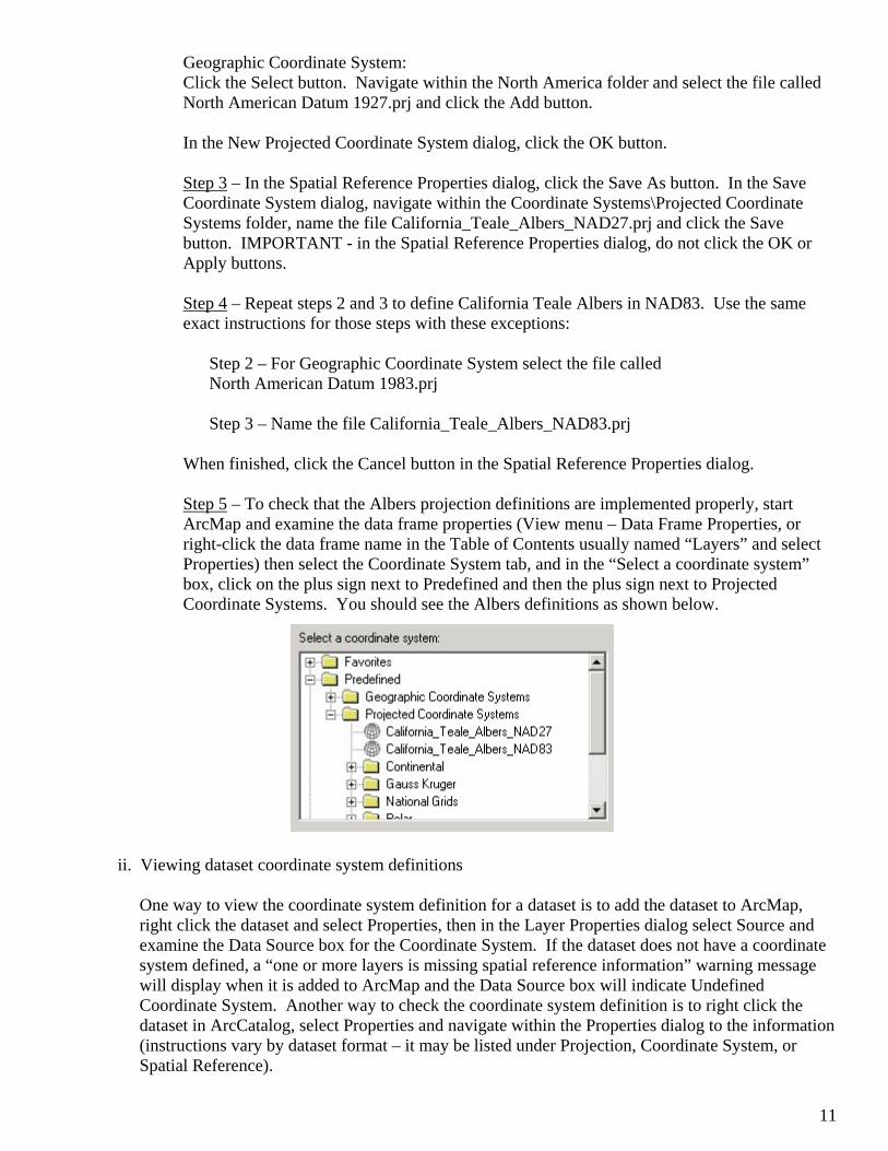
When finished, click the Cancel button in the Spatial Reference Properties dialog. Step 5 – To check that the Albers projection definitions are implemented properly, start ArcMap and examine the data frame properties (View menu – Data Frame Properties, or right-click the data frame name in the Table of Contents usually named “Layers” and select Properties) then select the Coordinate System tab, and in the “Select a coordinate system” box, click on the plus sign next to Predefined and then the plus sign next to Projected Coordinate Systems. You should see the Albers definitions as shown below.
ii. Viewing dataset coordinate system definitions
One way to view the coordinate system definition for a dataset is to add the dataset to ArcMap, right click the dataset and select Properties, then in the Layer Properties dialog select Source and examine the Data Source box for the Coordinate System. If the dataset does not have a coordinate system defined, a “one or more layers is missing spatial reference information” warning message will display when it is added to ArcMap and the Data Source box will indicate Undefined Coordinate System. Another way to check the coordinate system definition is to right click the dataset in ArcCatalog, select Properties and navigate within the Properties dialog to the information (instructions vary by dataset format – it may be listed under Projection, Coordinate System, or Spatial Reference).

12
iii. Defining coordinate systems for shapefiles and geodatabases Two options are discussed below. The first option uses the ArcToolbox Define Projection Wizard (shapefiles and geodatabase) and the second uses ArcCatalog. Once correct coordinate systems are defined, you can then convert the datasets to new versions of the datasets in a different projection and/or datum using the appropriate ArcToolbox Project Wizard. With correctly defined coordinate systems, you will also be able to on-the-fly project the datasets using ArcMap. ArcToolbox Define Projection Wizard (shapefiles and geodatabase) This wizard can be accessed from ArcToolbox under Data Management Tools - Projections. Example: Define the coordinate system for an Albers NAD27 shapefile or geodatabase Step 1 – Start the wizard and select the dataset. If a coordinate system is already defined for the dataset, you will receive a warning that if you continue, the wizard will overwrite the current coordinate system. If you suspect the current definition to be correct, click OK to the warning and Cancel out of the wizard. Otherwise, click the Next button. Step 2 – Click the Select Coordinate System button. In the Spatial Reference Properties dialog, click the Select button, then browse to the Projected Coordinate Systems folder and find the California_Teale_Albers_NAD27.prj file (if this file is not available, select Cancel for each wizard dialog and follow the steps in the section on setting California Teale Albers as a predefined projection, then re-start the wizard). Select the file and click the Add button. In the Spatial Reference Properties Dialog, click OK. Step 3 – Click Next, review the summary, then click Finish and a coordinate system will be defined for the dataset. Example: Define the coordinate system for a UTM Zone 10 NAD83 shapefile or geodatabase Step 1 – Same instructions as previous example. Step 2 – Click the Select Coordinate System button. In the Spatial Reference Properties dialog, click the Select button, then browse to the Projected Coordinate Systems - Utm – Nad 1983 folder and find the NAD 1983 UTM Zone 10N.prj projection file. Select the file and click the Add button. In the Spatial Reference Properties Dialog, click OK. Step 3 – Click the Next button, review the summary, then click Finish and a coordinate system will be defined for the dataset. ArcCatalog Coordinate systems for shapefiles or geodatabases can also be defined or edited using ArcCatalog. Example: Define the coordinate system for a State Plane Zone 3 NAD27 shapefile Step 1 - Start ArcCatalog, browse and find a shapefile that you know is stored in State Plane Zone 3 NAD27, but does not already have a coordinate system definition. Step 2 – Within ArcCatalog, right-click the shapefile and in the Shapefile Properties dialog select the Fields tab. Under the Field Name column, click on the Shape field name. Field Properties should now be shown. In the Field Properties section, click on the small grey button across from the Spatial Reference entry.

13
Step 3 – In the Spatial Reference Properties dialog, click the Select button and browse to the Projected Coordinate Systems – State Plane – Nad 1927 folder and find the NAD 1927 StatePlane California III FIPS 0403.prj file. Select the file and click the Add button. Click OK in both the Spatial Reference Properties and Shapefile Properties dialogs and a coordinate system will be defined for the dataset.
iv. Defining coordinate systems for coverages, grids, and TINs
ArcToolbox Define Projection Wizard (coverages, grids, and TINs) This wizard can be accessed from ArcToolbox under Data Management Tools - Projections. Once correct coordinate systems are defined, you can then convert the datasets to new versions of the datasets in a different projection and/or datum using the appropriate ArcToolbox Project Wizard. With correctly defined coordinate systems, you will also be able to on-the-fly project the datasets using ArcMap.
Example: Define the coordinate system for an Albers NAD27 coverage, grid, or TIN
Step 1 – Start the wizard. Decide whether you want to define the coordinate system interactively or define one to match existing data. If you choose the option to match existing data, you will need to choose an existing coverage, grid, or TIN dataset that is already defined in the same coordinate system (projection and datum). If you choose to match a dataset in Albers NAD27 or any other commonly used California projection, make sure it has a datum defined for it and not just a spheroid. The rest of this example describes how to define the coordinate system interactively. Step 2 – Choose the dataset that you want to assign a coordinate system. If a coordinate system is already defined for the dataset, you will receive a warning that if you continue, the wizard will overwrite the current coordinate system. If you suspect the current definition to be correct, click OK to the warning and Cancel out of the wizard (you can check the current definition for the dataset in ArcCatalog by right-clicking the dataset, select Properties, and then examine the Projection tab). Otherwise, click the Next button. Step 3 – Specify the projection. In the Projections list, select Albers Equal-Area. Click Next. For the projection parameters, use the following:
Units: meters 1st standard parallel: 34 00 00.0 2nd standard parallel: 40 30 00.0 Longitude of center of projection: -120 00 00.0 Latitude of origin of projection: 00 00 00 False easting: 0 False northing: -4000000 X shift (optional): 0 Y shift (optional): 0 Step 4 – Choose the datum or spheroid. Select the Datum option and choose NAD 1927 (US-NADCON). Click the Next button, review the summary, and a coordinate system will be defined for the dataset.

14
v. Defining coordinate systems for raster datasets (except grids)
ArcCatalog Coordinate systems for raster datasets (image files such as .bil, .img, .jpg, .tif, .sid) can be defined or edited using ArcCatalog. The storage method for the definition will vary by raster file format - see the Data Storage and Software Terminology section for more information. Datasets in TIFF format are reformatted to GeoTIFF with the definitions stored internally. There can be problems with TIFF reformatting – see the Frequently Asked Questions (FAQ) section for details. Example: Define the coordinate system for an Albers NAD27 raster dataset Step 1 - Start ArcCatalog, browse and find the raster dataset that you know is stored in Albers NAD27, but does not have a coordinate system definition. Step 2 - Within ArcCatalog, right-click the dataset and select Properties. In the Raster Dataset Properties dialog - Spatial Reference tab, click the Edit button.
Step 3 - In the Spatial Reference Properties dialog, click the Select button, then browse to the Projected Coordinate Systems folder and find the California_Teale_Albers_NAD27.prj (if this file is not available, quit ArcCatalog and follow the steps in the section on setting California Teale Albers as a predefined coordinate system, then return to step 1). Select the file and click the Add button. Click OK in the Spatial Reference Properties and Raster Dataset Properties dialogs and a coordinate system will be defined for the dataset. Note: For some raster datasets, you may need to refresh (View menu – Refresh option) or quit ArcCatalog to get the coordinate system definition to set properly.
vi. Converting shapefiles and geodatabases
Two options are discussed below. The first option uses the ArcToolbox Project Wizard (shapefiles and geodatabase) and the second uses ArcMap export from on-the-fly projection. These options will not update any measurement related fields for output shapefiles. Some geodatabase fields (“shape_area”, “shape_length”) will be automatically added or updated as long as the output is directed to a geodatabase - see the software help for more information. ArcToolbox Project Wizard (shapefiles and geodatabase) This wizard is accessed from ArcToolbox under Data Management Tools – Projections. It requires your input datasets to already have coordinate system definitions. Example: Convert an Albers NAD27 shapefile or geodatabase to Albers NAD83 Step 1 – Start the wizard and select the dataset. If the dataset does not have a coordinate system definition, you will receive a warning and not be able to convert it (see the examples on defining coordinate systems for assistance). Otherwise, the dataset will be added to the list of data to project. Click the Next button. Step 2 – Specify a name and location for the output dataset. Step 3 – Select the new coordinate system for the data. Click the Select Coordinate System button then in the Spatial Reference Properties dialog, click the Select button. Browse to the Projected Coordinate Systems folder and find the California_Teale_Albers_NAD83.prj file (if this file is not available, Cancel out of the wizard and follow the steps in the section on setting California Teale

15
Albers as a predefined coordinate system, then return to Step 1). Select the file and click the Add button. Click OK in the Spatial Reference Properties dialog and click Next. Step 4 – Select the geographic transformation. Click the Set Transformation button and in the Geographic Coordinate System Transformations dialog, choose to convert from GCS_North_American_1927 to GCS_North_American_1983 (these should be filled in automatically). In the “using:” list, choose NAD_1927_To_NAD_1983_NADCON. Click OK in the Geographic Coordinate System Transformations dialog, then click Next in the Project Wizard.
Step 5 – Review the coordinate extent information, then click Next to review a summary of the conversion. Click Finish and the dataset will be converted. ArcMap export from on-the-fly projection This option requires an understanding of ArcMap on-the-fly projection (see that section for details). Shapefile or geodatabase vector features can be added to ArcMap, on-the-fly projected to a different projection and/or datum (as determined by the data frame coordinate system setting), then exported to a new, permanently converted version of the dataset. The datasets added to ArcMap must have coordinate system definitions. Prior to export, any necessary geographic transformations must be set in the data frame properties. To export the data, right click the dataset name in the ArcMap table of contents and select Data – Export Data. In the Export Data dialog, select the category of features to export (All features, All features in View Extent, etc.) then choose the “Use same Coordinate System as the data frame” option and specify the output dataset location and name. Click OK and the dataset will be converted. Example: Convert a Geographic NAD27 shapefile or geodatabase to UTM Zone 10 NAD83 Step 1 – Start a new ArcMap session and make sure the data frame coordinate system is set to “No projection” (use the Clear button if necessary). Then, add the dataset to ArcMap and view the dataset’s coordinate system definition to ensure it is GCS_North_American_1927. Step 2 – Change the data frame coordinate system setting. From the View menu, select Data Frame Properties. In the Coordinate System tab, under “Select a coordinate system”, browse to Predefined - Projected Coordinate Systems – Utm – Nad 1983 and select the setting named NAD 1983 UTM Zone 10N. Click the Transformations button and in the Geographic Coordinate System Transformations dialog, choose to convert from GCS_North_American_1927 to GCS_North_American_1983. In the “using:” list, ensure that the transformation named NAD_1927_To_NAD_1983_NADCON is selected (the transformation should be chosen automatically in this case since it is a conversion between NAD27 and NAD83). Click OK in the Geographic Coordinate System Transformations dialog. Step 3 – Right-click the dataset name in ArcMap and export the projected data as discussed in the above description of this option.
vii. Converting coverages and grids
Two options are discussed below. The first option uses the ArcToolbox Project Wizard (coverages and grids) available only with ArcInfo. The second option uses ArcMap export from on-the-fly projection, which is available at all levels of ArcGIS Desktop (ArcView, ArcEditor, ArcInfo) but works for coverages only and not grids.

16
ArcToolbox Project Wizard (coverages and grids) - Available only with ArcInfo This wizard can be accessed from ArcToolbox under Data Management Tools – Projections. It is used to create a new version of the dataset in a different projection and/or datum. The wizard requires your input dataset to already have a coordinate system definition. Any measurement related fields for the output dataset will not automatically be updated. After converting coverages, the ArcToolbox Build Tool must be used to rebuild the original topology, which will also update measurement fields named “area”, “perimeter”, and “length” (other measurement fields will have to be manually updated). Example: Convert an Albers NAD27 coverage to Albers NAD83 Step 1 – Decide whether you want to project the data to a specified coordinate system (defined interactively) or project the data to match existing data. If you choose the option to match existing data, you will need to choose an existing coverage or grid dataset that is already in the desired output coordinate system (projection and datum). When selecting a dataset in any commonly used California coordinate system or projection, make sure it has a datum defined for it and not just a spheroid. The rest of this example describes how to project to a specified coordinate system. Step 2 – Choose the dataset to project. If the dataset does not have a coordinate system definition, you will receive a warning and not be able to convert that dataset (see the examples on defining coordinate systems for assistance). Otherwise, the current coordinate system parameters for the dataset will be shown. Click the Next button. Step 3 – Specify the output projection for the data. In the Projections list, select Albers Equal-Area. Click Next. For the projection parameters, use the following:
Units: meters 1st standard parallel: 34 00 00.0 2nd standard parallel: 40 30 00.0 Longitude of center of projection: -120 00 00.0 Latitude of origin of projection: 00 00 00 False easting: 0 False northing: -4000000 X shift (optional): 0 Y shift (optional): 0 Step 4 – Specify the output datum. Select NAD 1983 (US-NADCON). Click Next. Step 5 – Specify a name and location for the output dataset. Click the Next button, review the summary, click Finish, and the coverage will be converted. Step 6 – Use the Build Tool (available under Data Management Tools – Topology) to rebuild the topology of the converted dataset. Start the tool and select the new coverage. For Feature Class, select the type of features represented by the coverage (point, line, polygon, etc.) and click OK.
Example: Convert an Albers NAD27 grid to Albers NAD83 Step 1 – Determine the current input cell size of the grid. Start ArcCatalog, browse to the dataset, right-click on it and select Properties. In the Raster Dataset Properties dialog - General tab, look for the X or Y cell size (it should normally be the same for both) and write down this value. Start the Project Wizard. Decide whether you want to project the data to a specified coordinate system (defined interactively) or project the data to match existing data. If you choose the option to match

17
existing data, you will need to choose an existing coverage or grid dataset that is already in the desired output coordinate system (projection and datum). If you choose to match a dataset already in Albers NAD83 or any other commonly used California coordinate system or projection, make sure it has a datum defined for it and not just a spheroid. The rest of this example describes how to project to a specified coordinate system. Steps 2 through 4 – Same instructions as previous example. Step 5 – Specify a name and location for the output dataset. In the Grid settings section, for Resampling method, review the section on vector and raster data – formats and considerations to determine the best option. For cell size, it is recommended to specify the same cell size as the input grid (use the value determined in Step 1) unless converting to or from Geographic. Click the Next button, review the summary, click Finish, and the grid will be converted. Converting grids can take a long time, sometimes hours or days. There are faster ways to convert grids if the Project Wizard is too slow - see the Frequently Asked Questions (FAQ) section for assistance. ArcMap export from on-the-fly projection This option requires an understanding of ArcMap on-the-fly projection (see that section for details) and only works for coverages, not grids. Coverages can be added to ArcMap, on-the-fly projected to a different projection and/or datum (as determined by the data frame coordinate system setting), then exported to a new, permanently converted version of the dataset. The coverages added to ArcMap must have coordinate system definitions. If a geodatabase is chosen as the output export format, some fields (“shape_area”, “shape_length”) will be automatically added or updated. Prior to export, any necessary geographic transformations must be set in the data frame properties. To export the data, right-click the dataset name in the ArcMap table of contents and select Data – Export Data. In the Export Data dialog, select the category of features to export (All features, All features in View Extent, etc.) then choose the “Use same Coordinate System as the data frame” option, and specify output dataset location and name. Click OK and the dataset will be converted. Example: Convert a State Plane Zone 7 NAD27 coverage to UTM Zone 11 NAD83 Step 1 – Start a new ArcMap session and make sure the data frame coordinate system is set to “No projection” (use the Clear button if necessary). Add the dataset to ArcMap and view the dataset’s projection definition to ensure it is NAD_1927_StatePlane_California_VII_FIPS_0407. Step 2 – Change the data frame coordinate system setting. From the View menu, select Data Frame Properties. In the Coordinate System tab, under “Select a coordinate system”, browse to Predefined - Projected Coordinate Systems – Utm – Nad 1983 and select the setting named NAD 1983 UTM Zone 11N. Click the Transformations button and in the Geographic Coordinate System Transformations dialog, choose to convert from GCS_North_American_1927 to GCS_North_American_1983. In the “using:” list, ensure that the transformation named NAD_1927_To_NAD_1983_NADCON is selected (the transformation information should be selected automatically in this case since it is a conversion between NAD27 and NAD83). Click OK in the Geographic Coordinate System Transformations dialog. Step 3 – Right-click the dataset name in ArcMap and export the projected data as discussed in the above description of this option.
viii. Converting raster datasets (except grids) There are a few options to convert raster datasets using ArcGIS Desktop 8.x software. One option is to change the datasets to grid format and follow the examples on converting grid data. Another
18
option is to use the “Project Raster” sample tool provided with the software in the optionally installed ArcObjects Developer Kit – look for it in the install path in a location such as: c:\arcgis\arcexeXX(where XX = software version)\ArcObjects Developers Kit\Samples\ Raster\ProjectRaster\ProjectRaster.exe – double-click the .exe file and follow the instructions. The tool does not allow the user to select a geographic transformation for the conversion. A newer version of the tool may be available for download from: http://arcobjectsonline.esri.com in the Samples – Raster section of the website. See the Frequently Asked Questions (FAQ) section for a discussion of raster projection accuracy in ArcGIS Desktop.
ix. Updating attributes
If you need to manually update any measurement-related fields (such as area and length) in attribute tables, specific instructions are available in the software help (Help Menu - ArcGIS Desktop Help - Contents tab - ArcMap - Working with tables - Making field calculations). There are also software extensions and scripts available to help do these types of recalculations. A useful extension for ArcGIS called “XTools” can be downloaded along with other extensions and scripts from the ESRI ArcScripts web site: http://arcscripts.esri.com
x. On-the-fly projection
ArcMap can temporarily on-the-fly project datasets on-screen to a new projection and/or datum as needed. This convenient technology works for vector, raster, and TIN formats, and keeps users from having to permanently convert and store multiple versions of datasets in different projections and datums. Coordinate system definitions must exist for datasets that are on-the-fly-projected. The on-the-fly projection process is controlled from the ArcMap data frame coordinate system setting (right click on the data frame title – usually called “Layers” in the Table of Contents, select Properties – then in the Data Frame Properties dialog select the Coordinate System tab). When the “Current coordinate system” box is set to a valid coordinate system, all datasets in the data frame will be automatically projected on-screen to that coordinate system. If any of the datasets do not have coordinate system definitions, you will receive a “one or more datasets is missing spatial reference information” warning - those datasets will be unaffected by the data frame coordinate system setting and left in their stored projection and datum. When starting a new map document (.mxd file), the data frame coordinate system is set by the first dataset added to the data frame that has a coordinate system definition. On-the-fly projection is disabled if the data frame’s coordinate system setting indicates “No projection” - this can also be toggled by using the Clear button next to the “Current coordinate system” box. The data frame coordinate system will be reset by the next dataset added to the data frame that has a coordinate system definition. If any of the datasets use coordinate systems with GCS definitions that differ from the other datasets or the data frame’s coordinate system setting, you may receive an advisory warning about selecting a geographic transformation. A transformation will be selected automatically, but it may not be the correct one to use. To review the selected transformation, return to the Data Frame Properties dialog - Coordinate System tab and select the Transformations button. The current GCS definitions used by the datasets are shown in the “Convert from:” box. The target GCS definition used by the data frame coordinate system setting is shown as the “into:” selection. Click on each GCS definition in the “Convert from” box to see the current transformation settings. The NAD_1927_To_NAD_1983_NADCON transformation should be chosen when converting between GCS_North_American_1927 and GCS_North_American_1983. The Frequently Asked Questions (FAQ) section has a list of other transformations that can be used in California and North America.

19
C. ArcGIS Desktop 9.x (ArcView, ArcEditor, ArcInfo) i. California Teale Albers now included as a predefined coordinate system
The ArcGIS Desktop 9.x software installation includes numerous predefined coordinate systems that are classified as Geographic Coordinate Systems (GCS) and Projected Coordinate Systems (PCS). The predefined coordinate systems are stored in .prj files in the installation path at a location such as: C:\Program Files\ArcGIS\Coordinate Systems These .prj files are used by many aspects of the ArcGIS software, including defining coordinate systems for datasets and on-the-fly projection.
Beginning at ArcGIS Desktop 9.x, California Teale Albers is included with the software as a predefined coordinate system in both NAD83 and NAD27 datums. The two definitions are stored within the installation path at \Coordinate Systems\Projected Coordinate Systems\State Systems. Shown below is how the definitions should appear when viewed through the ArcMap Data Frame Properties - Coordinate System tab. In the “Select a coordinate system:” box, expand Predefined, then Projected Coordinate Systems, then State Systems.
ii. Viewing dataset coordinate system definitions
One way to view the coordinate system definition for a dataset is to add the dataset to ArcMap, right click the dataset and select Properties, then in the Layer Properties dialog examine the Source tab for the information. If the dataset does not have a coordinate system defined, a “one or more layers is missing spatial reference information” warning message will display when it is added to ArcMap and the Data Source box will indicate Undefined Coordinate System. Another way to check the coordinate system definition is to right click the dataset in ArcCatalog, select Properties and navigate within the Properties dialog to the information (instructions vary by dataset format – it may be listed under Projection, Coordinate System, or Spatial Reference).
iii. Defining coordinate systems for datasets
Coordinate systems for most dataset formats (vector, raster, TIN) can be defined using the ArcToolbox Define Projection Tool (description and examples provided below) or ArcCatalog (same as ArcGIS Desktop 8.x instructions). Raster datasets in TIFF format are reformatted to GeoTIFF with the definitions stored internally. There can be problems with TIFF reformatting – see the Frequently Asked Questions (FAQ) section for details. ArcToolbox Define Projection Tool The tool can be accessed from ArcToolbox under Data Management Tools – Projections and Transformations – Define Projection. Once correct coordinate systems are defined, you can use an appropriate projection tool to convert them, or on-the-fly project them in ArcMap.

20
Example: Define the coordinate system for a Geographic NAD27 shapefile or geodatabase Step 1 – Start the Define Projection Tool and select the dataset. If a coordinate system is already defined for the dataset, you will notice a warning symbol next to the Input Dataset or Feature Class box. If you continue when the warning symbol is shown, the tool will overwrite the current coordinate system. If you suspect the current definition to be correct, Cancel out of the tool. Otherwise, click the OK button.
Step 2 – Click the Coordinate System button. In the Spatial Reference Properties dialog, click the Select button, then browse to the Geographic Coordinate Systems – North America folder and find the North American Datum 1927.prj file. Select the file and click the Add button. In the Spatial Reference Properties Dialog, click OK. Then click OK in the Define Projection dialog and a process dialog will appear showing the tool progress and results. Example: Define the coordinate system for a UTM Zone 11 NAD83 raster dataset Step 1 – Same instructions as previous example.
Step 2 – Click the Coordinate System button. In the Spatial Reference Properties dialog, click the Select button, then browse to the Projected Coordinate Systems - Utm – Nad 1983 folder and find the NAD 1983 UTM Zone 11N.prj file. Select the file and click the Add button. In the Spatial Reference Properties Dialog, click OK. Then click OK in the Define Projection dialog and a dialog will appear showing the tool progress and results.
iv. Converting shapefiles and geodatabases
Shapefiles and geodatabases can be converted using the ArcToolbox Project Tool (description and example provided below) or using ArcMap export from on-the-fly projection (same as described in the ArcGIS Desktop 8.x instructions on converting shapefiles and geodatabases). These options will not update any measurement related fields for output shapefiles. Some geodatabase fields (“shape_area”, “shape_length”) will be automatically added or updated as long as the output is directed to a geodatabase - see the software help for more information. ArcToolbox Project Tool This tool can be accessed from ArcToolbox under Data Management Tools – Projections and Transformations – Feature – Project. The tool requires your input datasets to already have coordinate system definitions. Example: Convert an Albers NAD27 shapefile or geodatabase to Albers NAD83 Step 1 – Start the Project Tool and select the dataset. If the dataset does not have a coordinate system definition, an error symbol will appear and you will not be able to convert it (see the examples on defining coordinate systems for assistance). Step 2 – Specify the output dataset. An output dataset location and name may be specified by default, but can be changed by typing or selecting a new location and name. Step 3 – Select the output coordinate system for the data. Click the button and in the Spatial Reference Properties dialog, click the Select button. Browse to Projected Coordinate Systems – State Systems – select the NAD 1983 California (Teale) Albers.prj file, click Add and then OK.

21
Step 4 – Select the Geographic Transformation. Click the drop-down arrow and in the list select NAD_1927_To_NAD_1983_NADCON. Then click OK and a dialog will appear showing the tool progress and results.
v. Converting coverages Coverages can be converted using the ArcToolbox Project Tool for Coverages available only with ArcInfo. Another option is to use ArcMap export from on-the-fly projection, which is available at all levels of ArcGIS Desktop (ArcView, ArcEditor, ArcInfo), and is the same as described in the ArcGIS Desktop 8.x instructions on converting coverages. ArcToolbox Project Tool for Coverages - Available only in ArcInfo This tool can be accessed from ArcToolbox under Coverage Tools - Data Management - Projections - Project. Any measurement related fields for the output coverage will not automatically be updated. After conversion, the ArcToolbox Build Tool (Data Management - Topology - Build) must be used to build the topology on the new coverage, which will also update measurement fields named “area”, “perimeter”, and “length” (other measurement fields will have to be manually updated). Example: Convert an Albers NAD27 coverage to Albers NAD83 Step 1 – Browse and select the input coverage. A warning symbol will be indicated if the coverage does not have a coordinate system definition. A coordinate system definition is not needed as long as the input projection is indicated in the projection file in Step 3. Step 2 – Specify the output coverage. An output coverage name and location may be chosen by default, but can be changed by typing or selecting a new location and name. Step 3 – Specify a projection file. A projection file is a plain text file that lists the input and output parameters for the conversion. The file can be created in a text editor such as Notepad or WordPad. For this example, open a text editor and paste-in the lines below, then save the file with a meaningful name such as “albnad27_albnad83.txt” and specify it when using the tool.
INPUT PROJECTION ALBERS SPHEROID CLARKE1866 DATUM NAD27 UNITS METERS PARAMETERS 34 00 00 40 30 00 -120 00 00 00 00 00 0 -4000000 OUTPUT PROJECTION ALBERS SPHEROID GRS80 DATUM NAD83 UNITS METERS PARAMETERS 34 00 00 40 30 00 -120 00 00 00 00 00 0 -4000000 END
22
Refer to the software help for assistance with parameters for other projections. Experienced ArcInfo Workstation users may recognize this file structure from the PROJECT command. Projection files successfully used with the PROJECT command can be also be used with this tool. Step 4 – Click OK and a dialog will appear showing the tool progress and results.
vi. Converting raster datasets
Three options are discussed below. See the Frequently Asked Questions (FAQ) section for a discussion of raster projection accuracy in ArcGIS Desktop – it applies to all of the options. First, an ArcToolbox Project Raster Tool is available (Data Management Tools – Projections and Transformations – Raster – Project Raster) but at 9.0 it does not allow the user to select a geographic transformation for the conversion. Second, there is a “Project Raster” sample tool provided with the software in the optionally installed ArcObjects Developer Kit in a path location such as: c:\Program Files\ArcGIS \DeveloperKit\samples\Raster\Raster_Spatial_Reference\ProjectingRaster\. However, at 9.0 it does not allow the user to select a geographic transformation for the conversion. A newer version of the tool is available for download from: http://arcgisdeveloperonline.esri.com in the Samples – Raster – Raster Spatial Reference section of the website. This version does allow the user to select a geographic transformation for the conversion. Download the zip file, extract it, double-click the .exe file within the Visual_Basic folder and follow the instructions. Third, ArcMap export from on-the-fly projection at 9.0 now allows exporting raster as well as vector datasets. This option requires an understanding of ArcMap on-the-fly projection (see that section for details). Raster datasets can be added to ArcMap, on-the-fly projected to a different projection and/or datum (as determined by the data frame coordinate system setting), then exported to permanently converted versions of the datasets. The raster datasets added to ArcMap must have coordinate system definitions. Prior to export, any necessary geographic transformations must be properly set in the data frame properties. To export the data, right-click the dataset name in the ArcMap table of contents and select Data – Export Data. In the Export Data dialog, select Data Frame (Current) for the Spatial Reference setting, specify other options including the output file location and format, then click Save and the dataset will be converted.
vii. Updating attributes If you need to manually update any measurement-related fields (such as area and distance) in attribute tables, instructions are available in the ArcGIS software help (Help Menu - ArcGIS Desktop Help - Contents tab - ArcMap - Working with tables - Making field calculations). There are also software extensions and scripts available to help do these types of recalculations. A useful extension for ArcGIS called “XTools” can be downloaded along with other extensions and scripts from the ESRI ArcScripts web site: http://arcscripts.esri.com
viii. On-the-fly projection
On-the-fly projection for ArcGIS Desktop 9.x using ArcMap is basically the same as described in the ArcGIS Desktop 8.x section with a few changes. There is a new a setting to “Favor rendering speed over accuracy” in ArcMap as well as other core ArcGIS programs (ArcCatalog, ArcScene, ArcGlobe…), under Tools menu - Options - Raster tab - General tab - Projection Accuracy Settings. An improved raster projection algorithm has also been implemented - see the Frequently Asked Questions section for a discussion of ArcGIS raster projection for more information.

23
6. Frequently Asked Questions (FAQ)
DFG Questions
Q: So DFG is converting to NAD83, does this mean I need to go back and convert all my existing NAD27 GIS data?
A: No. You should try to start working in NAD83 as you begin new projects and as data become available. For ongoing projects, you will need to decide whether to continue in NAD27 or convert to NAD83.
Q: As a DFG employee or cooperator, where can I find NAD83 GIS data?
A: DFG has a NAD83 Spatial Data Framework CD available that provides many frequently-used base datasets. An all-NAD83 online GIS Library of data is also available internally to DFG staff (contact [email protected] for Framework CD and GIS Library information). The California Spatial Information Library (CaSIL) at http://gis.ca.gov has NAD83 data, including USGS Digital Orthophoto Quadrangle (DOQ) airphotos, Digital Raster Graphic (DRG) topo/quad maps, and Landsat satellite imagery. Other organizations are starting to produce more NAD83 data as well.
Q: When trying to convert or on-the-fly project shapefiles from the March 2000 DFG Spatial Data Framework CDs, there appears to be an accuracy problem?
A: There is a known problem with the coordinate system definitions (.prj files) associated with the shapefiles on the March 2000 Spatial Data Framework CDs - they are slightly inaccurate in the way they were defined. Please do not use those CDs or the datasets on them. There are newer Spatial Data Framework CDs that do not have this problem and also contain more current data in NAD83 instead of NAD27. Contact the GIS Service Center for assistance (email [email protected]).
Software Questions Q: I have both ArcView 3.x and ArcGIS Desktop software available, which one should I use to convert (reproject) my shapefiles?
A: The ArcView 3.x California Shapefile Projector extension is the easiest option for California data, and will also update some measurement attributes related to area and distance. A batch conversion tool is included However, the software may be slow when converting large datasets.
Q: What does that message “One or more layers is missing spatial reference information. Data from those layers cannot be projected.” mean in ArcMap?
A: This means that one or more datasets/layers in the ArcMap data frame are missing coordinate system definitions and cannot be on-the-fly projected. Those datasets will only be displayed in their original projection and datum. To keep this message from appearing, define coordinate systems for the datasets/layers.
Q: Does ArcMap on-the-fly projection work for map services (live data and maps - ArcIMS image and feature services, etc.)?
A: Yes. As long as the map service includes coordinate system information, you can follow the same procedures as discussed for on-the-fly projecting datasets. If the map service does not have coordinate system information, you will receive a warning that it cannot be projected.

24
Q: What geographic transformations should I use with ESRI software (such as the ArcView Projection Utility, ArcToolbox Project Wizards/Tools, and ArcMap on-the-fly projection)?
A: There are numerous transformations available to use with ESRI software. Detailed lists for different parts of the world are available with each GIS software program. Here are some transformations that can be used in California and North America. Despite the direction indicated in the transformation name, they can be used in the opposite direction as well. For example, the NAD_1927_To_NAD_1983_NADCON transformation can be used from NAD83 to NAD27 as well as the opposite direction from NAD27 to NAD83. Transformation Area of Use
NAD_1927_To_NAD_1983_NADCON NAD27 to NAD83 – Continental U.S. (CONUS) NAD_1927_To_WGS_1984_4 Mean for U.S. (CONUS) NAD_1927_To_WGS_1984_6 Mean for U.S. (CONUS West of Mississippi River) NAD_1983_To_WGS_1984_1 Canada, C. America, Mexico, and U.S. (Alaska, CONUS) NAD_1983_To_WGS_1984_5 Contiguous U.S. NAD_1983_To_HARN_CA_N California North HARN - above 37 degrees latitude NAD_1983_To_HARN_CA_S California South HARN - below 37 degrees latitude
Q: How accurate is ArcGIS Desktop projection for raster datasets (including on-the-fly projection, the sample project raster tools, and the Project Raster tool in ArcToolbox 9.x)? What is the most accurate way to convert/reproject raster datasets in ArcGIS?
A: There are differences in how ArcGIS Desktop 8.x and 9.x handle raster projection, as discussed below. The potentially most accurate way to convert/reproject raster datasets is to use tools provided with the ArcInfo level of ArcGIS (including ArcInfo Workstation). ArcGIS Desktop 8.x According to ESRI for version 8.3, “the current implementation of projecting raster datasets is based on a single polynomial transformation with 16 x 16 control points regardless how big images are. There could be some distortion when the image covers a big area or close to North or South poles. The result is good when projecting small images like within 1 degree and with latitude that is between -70 and 70 degrees.”
ArcGIS Desktop 9.x According to ESRI for version 9,0, “the raster reprojection engine was improved to perform a piecewise polynomial or least squares fit (depending on the raster) transformation with a 64 x 64 matrix of control points. This method produces a lot better results than those found in 8.3.”. Note: The ArcGIS Desktop 9.x help files may incorrectly indicate an older raster projection method in some places (such as with the ArcToolbox Project Raster tool). ArcGIS / ArcInfo Workstation 8.x + The ArcInfo Workstation PROJECT and PROJECTGRID commands provide the potentially most accurate (and slowest) way of converting/reprojecting raster datasets in grid format. These commands allow for a cell-by-cell conversion of grid data (PROJECT by default using the GRID option, PROJECTGRID using the FULL option). In the ArcInfo level of ArcGIS Desktop 8.x, this capability was implemented with the ArcToolbox Project Wizard (coverages and grids).
25
Q: I have many (hundreds or thousands) of GIS datasets that I would like to convert to a different projection and/or datum, what should I do?
A: Assess the data and your software options using the topics discussed in this document. Additional assistance and batch processing scripts are available from the GIS Service Center (see Support Resources section) or ESRI’s ArcScripts website (http://arcscripts.esri.com). If you have ArcGIS Desktop software, consider assigning coordinate system definitions to your datasets and on-the-fly project them as necessary instead.
Q: Why is the projection name “Custom” sometimes used for the California Teale Albers projection when using ESRI software?
A: The PROJCS name “Custom” can be used within the coordinate system (.prj) files for the California Teale Albers projection so that it is recognized by the ArcView 3.2+ Projection Utility (AVPU) as well as ArcGIS Desktop and other ESRI programs. There are other PROJCS names that are used for this projection, but they may not be recognized by the AVPU. Thus, if you produce datasets for ArcView 3.x users, the PROJCS name “Custom” can make it easier for them to manage and convert the datasets while retaining compatibility with other software. Here is how the PROJCS name of “Custom” should appear within the .prj files: PROJCS["Custom",GEOGCS["GCS_North_American_ …
Q: I have a dataset in NAD27 that doesn’t on-the-fly project or convert properly to NAD83 using ArcGIS Desktop. What could I be doing wrong? Why does the GCS or datum in the input coordinate system definition show as Clarke_1866 instead of North_American_1927?
A: Some datasets in NAD27 contain coordinate system definitions that are slightly inaccurate or incomplete. The definitions may indicate the GCS or datum as Clarke_1866, which is correctly based on the spheroid used by NAD27, but is incomplete and not recognized automatically for geographic transformations in ArcMap. The NAD_1927_To_NAD_1983_NADCON transformation looks for coordinate system definitions with a GCS of North_American_1927, and won’t recognize a GCS of Clarke_1866. The result is that the dataset may on-the-fly project or convert to the new coordinate system space, but it may not be accurate since the appropriate geographic transformation was not automatically selected, or was not available to be selected in the list of transformations. To correct this problem, ensure that NAD27 datasets use a GCS of North_American_1927 instead of Clarke_1866. Use ArcCatalog to edit the coordinate system definitions, or delete the definitions and redefine them correctly.
Other Questions
Q: I just have coordinate values (such as in a spreadsheet or text file) that I need to convert to a different coordinate system or datum, how can I do this?
A: Here are some conversion utilities that can be freely downloaded:
CORPSCON http://crunch.tec.army.mil/software/corpscon/corpscon.html
GEOTRANS
http://earth-info.nga.mil/GandG/geotrans

26
Q: How much distance is there between NAD27 and NAD83 data? Will I be able to tell if I’m accidentally using NAD27 and NAD83 data together at the same time?
A: The distance between NAD27 and NAD83 data will vary somewhat by projection and location. In the California Teale Albers projection, a point in NAD27 will be approximately 200 meters away from the same point in NAD83. When zoomed-out and looking at the full extent of regional or statewide data (medium to small scale), you may not be able to tell the difference.
Q: GIS work was easier when all datasets were Albers NAD27 and everything aligned without the need to be concerned about different projections and datums. Will it ever be like this again?
A: The increasing use of NAD83 imagery and GPS technology are forcing many organizations to examine their mapping trends and to consider migrating from NAD27. After a transition period for the conversion and distribution of key NAD83 datasets, the situation will likely settle down to where more GIS datasets will be in the same projection and datum.
Q: Instead of using one of the software tools to define coordinate systems, can I just use an existing coordinate system definition file, copy it, and manually associate it with each dataset?
A: This approach works for some dataset formats, including shapefiles, coverages, grids, and TINs. For example, if you have a correctly defined .prj file for an Albers NAD83 shapefile, you can copy and rename it appropriately for other shapefiles you know are also in the same projection and datum. For coverages, grids, and TINs, you can copy a correctly defined prj.adf file into the dataset folders.
Q: What are some of the issues or problems involved with defining coordinate systems for TIFF format raster datasets?
A: TIFF format raster datasets can store georeferencing and coordinate system information inside “tags” within the TIFF file header (when reformatted to GeoTIFF). Georeferencing information can also be stored in an accompanying world file (a separate file with an extension such as .tfw). Sometimes when both sources of georeferencing information are present, each source can be interpreted slightly different by particular GIS programs. Some programs may also look for one particular source before the other (internal tags have precedence over a world file, or vice-versa). Regardless of the source that is used, it may be necessary to apply a fix to TIFF datasets to ensure that the information is encoded and interpreted correctly. For more information about these issues as it relates to ESRI software, visit the ESRI Support Center at http://support.esri.com and search on separate topics such as “GeoTIFF tags” or “TIFF world file” for bug reports, correction tips, and related resources. A free RAster Georeference Enabler (RAGE) tool developed by 3001, Inc. is available to create, complete, or correct georeferencing information for selected raster files (GeoTIFF) in batch mode. It can be found at http://www.3001inc.com in the downloads section, or directly from this URL http://www.3001inc.com/3001website/main/downloads_files/rage/geotiff_header_repair.htm along with additional information about GeoTIFF reformatting issues. GeoTIFF Information and Support http://www.remotesensing.org/geotiff/geotiff.html
Q: I’m getting tired of reading this document, will it ever end?
A: Yes, you’re almost there.

27
7. Support Resources DFG GIS Service Center - providing technical assistance with DFG GIS data issues. Email: [email protected] http://www.dfg.ca.gov/itbweb/gis/gis_index.htm ESRI ArcScripts - including tools and utilities for converting between projections and datums. http://arcscripts.esri.com ESRI Software Discussion Forums - including specific forums for projection topics. Questions posted within the forums are routinely answered by ESRI staff and knowledgeable users. http://forums.esri.com ESRI Support Center - gateway to many ESRI support resources. http://support.esri.com ESRI Virtual Campus - GIS education and training on the web. http://campus.esri.com National Geodetic Survey - including frequently asked questions (FAQ) about datums. http://www.ngs.noaa.gov Understanding Map Projections This booklet is provided with ArcGIS software in printed or digital format.