developments in blade shape design for a darrieus vertical ... · in 1974, blackwell and reis, in...
TRANSCRIPT

SANDIA REPORTSAND86-- 1085 Unlimited Release UC–60Printed September 1986
,
Developments in Blade ShapeDesign for a Darrieus VerticalAxis Wind Turbine
Thomas D. Ashwill, Timothy M. Leonard
Prepared by
Sandia National LaboratoriesAlbuquerque, New Mexico 87185 and Livermore, California 94550
for the United Statea Department of Energyunder Contract DE-AC04-76DPO0789
SF ?9[)O(jf,8 31I
,
Issued by Sandia National Laboratories, operated for the United StatesDepartment of Energy by Sandia Corporation.
NOTICE. This report was prepared as an account of work sponsored by anagency of tbe United States Government. Neither the United States Govern-ment nor any agency thereof, nor any of their employees, nor any of theircontractors, subcontractors, or their employees, makes any warranty, ex-press or implied, or assumes any legal liability or responsibility for theaccuracy, completeness, or usefulness of any information, apparatus, prod-uct, or process disclosed, or represents that its use would not infringeprivately owned rights. Reference herein to any specific commercial product,prucess, or service by trade name, trademark, manufacturer, or otherwise,does not necessarily constitute or imply its endorsement, recommendation,or favoring by the United States Government, any agency thereof or any oftheir contractors or subcontractors. The views and opinions expressed here-in do not necessarily state or reflect those of the United States Government,any agency thereof or any of their contractors or subcontractors.
Printed in the United States of AmericaAvailable fromNationalTechnical Information ServiceU.S. Department of Commerce5285 Port Royal RoadSpringfield, VA 22161
NTIS price codesPrinted copy: A02Microfiche copy: AO1
.
2
SAND86– 1085Unlimited Release
Printed September 1986
DistributionCategory UC –60
Developments in Blade Shape Design for aDarrieus Vertical Axis Wind Turbine
Thomas D. AshwillWind Energy Research Division
Timothy M. LeonardAdvanced Systems Development Division II
Sandia National LaboratoriesAlbuquerque, NM 87185
AbstractA new computer program package has been developed that determines the troposkein shapefor a Darrieus Vertical Axis Wind Turbine Blade with any geometrical configuration orrotation rate. This package allows users to interact and develop a “buildable” blade whoseshape closely approximates the troposkein. Use of this package can significantly reduceflatwise mean bending stresses in the blade and increase fatigue life.
3-4
———-——— .———.. — .——.-..—._. ——. ————

—
Developments in Blade Shape Design for aDarrieus Vertical Axis Wind Turbine
IntroductionAs the wind turbine industry enters an era with-
out government tax credits, it becomes increasinglyimportant that the cost per kilowatt hour of wind-produced power be substantially reduced. Wind tur-bines that are less expensive to manufacture but moredependable to operate are required in order to com-pete with other sources of energy. New turbine de-signs, therefore, must become less conservative andincorporate improved fatigue design and analysistechniclues for increased turbine longevity.
Vertical Axis Wind Turbine(VAWT) blades, be-cause of their large oscillatory loading conditions, arevery susceptible to fatigue failure. When combinedwith the oscillatory loading, the mean loading due tocentrifugal forces and gravity also contributes signifi-cantly to fatigue damage. One way of lowering meanstresses and extending the fatigue life is to design theblade such that its shape closely approximates anideal shape called the troposkien or “skipping-rope”shape. This reduces the flatwise bending stresses dueto centrifugal and gravitational forces as the bladetends to displace less from its original shape. Recentlya methodology for designing an improved blade shapeand thus lowering the mean stresses for VAWTS wasdeveloped at Sandia and is the subject of this report.
Development of DarrieusBlade Shape
It was realized early in the development ofDarrieus VAWTS that the shape of the blade wasimportant. G. J. M. Darrieus states in his 1931 U.S.patent (of a VAWT that each blade should “have astream-line outline curved in the form of a skippingrope.’” More recently, in the early 1970’s, the NationalResearch Council of Canada independently developedthe concept of a VAWT and noted that under theaction of centrifugal forces, a perfectly flexible bladeassumes the approximate shape of a catenary.* This isnot precise, however, as a catenary is the shape formedby a perfectly flexible cable of uniform density and
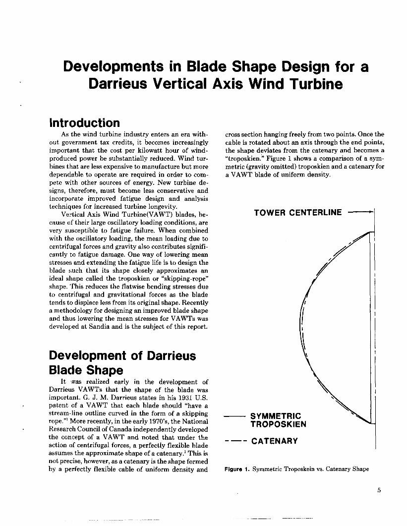
cross section hanging freely from two points. Once thecable is rotated about an axis through the end points,the shape deviates from the catenary and becomes a“troposkien.” Figure 1 shows a comparison of a sym-metric (gravity omitted) troposkien and a catenary fora VAWT blade of uniform density.
TOWER CENTERLINE ~1I
/
/
I
SYMMETRICTROPOSKIEN
- —- CATENARY
Figure 1. Symmetric Troposkein vs. Catenary Shape
5
In 1974, Blackwell and Reis, in their report, BladeShape for a Troposkien Type of Vertical-Axis WindTurbine,’ defined the term troposkien as “the shapeassumed by a perfectly flexible cable of uniform den-sity and cross section if its ends are attached to twopoints on a vertical axis and it is then spun at constantangular velocity about that vertical axis.” Since aVAWT blade is not perfectly flexible, it should bebent or formed as closely as possible into the shape itwould become during rotation if it were flexible, thusminimizing the flatwise bending stresses. Blackwelland Reis developed the equations that geometricallydescribe a troposkien shape for a blade of uniformdensity and used an iterative solution of these equa-tions in their computer program TROP. The equa-tions were developed for only half the blade, andgravity effects were neglected in the solution; thus, theresulting troposkiens were symmetric about the equa-tor. This was a good approximation for high-rotation-rate, small-diameter turbines like the Sandia 2-mturbine.z
In the late 1970’s the iterative technique em-ployed by Blackwell and Reis to define any uniform-density troposkien was extended by Sandia to includegravitational effects and blades of three differentcross sections. These modifications were implementedin the computer program BENDO.
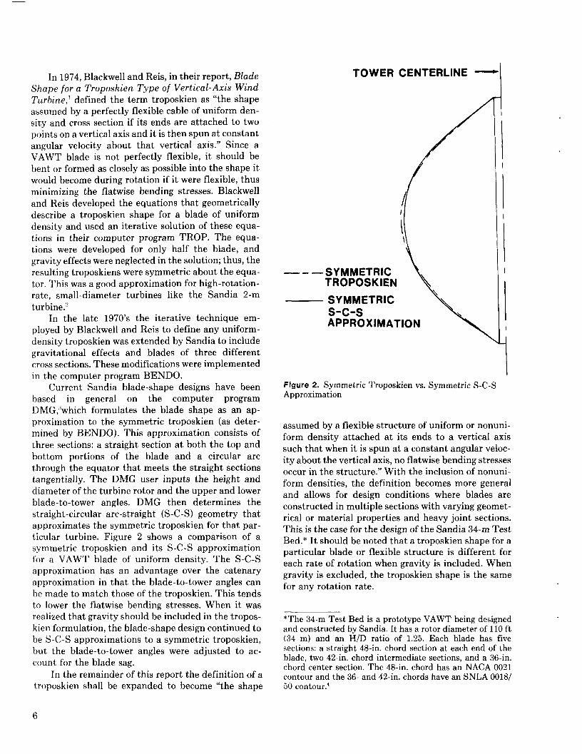
Current Sandia blade-shape designs have beenbased in general on the computer programDMG,:’which formulates the blade shape as an ap-proximation to the symmetric troposkien (as deter-mined by BENDO). This approximation consists ofthree sections: a straight section at both the top andbottom portions of the blade and a circular arcthrough the equator that meets the straight sectionstangentially. The DMG user inputs the height anddiameter of the turbine rotor and the upper and lowerblade-to-tower angles. DMG then determines thestraight-circular arc-straight (S-C-S) geometry thatapproximates the symmetric troposkien for that par-ticular turbine. Figure 2 shows a comparison of asymmetric troposkien and its S-C-S approximationfor a VAWT blade of uniform density. The S-C-Sapproximation has an advantage over the catenaryapproximation in that the blade-to-tower angles canbe made to match those of the troposkien. This tendsto lower the flatwise bending stresses. When it wasrealized that gravity should be included in the tropos-kien formulation, the blade-shape design continued tobe S-C-S approximations to a symmetric troposkien,but the blade-to-tower angles were adjusted to ac-count for the blade sag.
In the remainder of this report the definition of atroposkien shall be expanded to become “the shape
TOWER CENTERLINE —
—–—SYMMETRICTROPOSKIEN \ \
SYMMETRICs-c-sAPPROXIMATION
\
\
\
Figure 2. Symmetric Troposkien VS,Approximation
Symmetric S-C-S
assumed by a flexible structure of uniform or nonuni-form density attached at its ends to a vertical axissuch that when it is spun at a constant angular veloc-ity about the vertical axis, no flatwise bending stressesoccur in the structure.” With the inclusion of nonuni-form densities, the definition becomes more generaland allows for design conditions where blades areconstructed in multiple sections with varying geomet-rical or material properties and heavy joint sections.This is the case for the design of the Sandia 34-m TestBed.* It should be noted that a troposkien shape for aparticular blade or flexible structure is different foreach rate of rotation when gravity is included. Whengravity is excluded, the troposkien shape is the samefor any rotation rate.
*The 34-m Test Bed is a prototype VAWT being designedand constructed by Sandia. It has a rotor diameter of 110 ft(34 m) and an H/D ratio of 1.25. Each blade has fivesections: a straight 48-in. chord section at each end of theblade, two 42-in. chord intermediate sections, and a 36-in.chord center section. The 48-in. chord has an NACA 0021
contour and the 36- and 42-in. chords have an SNLA 0018/50 contour.4
6
Development of NewTroposkien Program
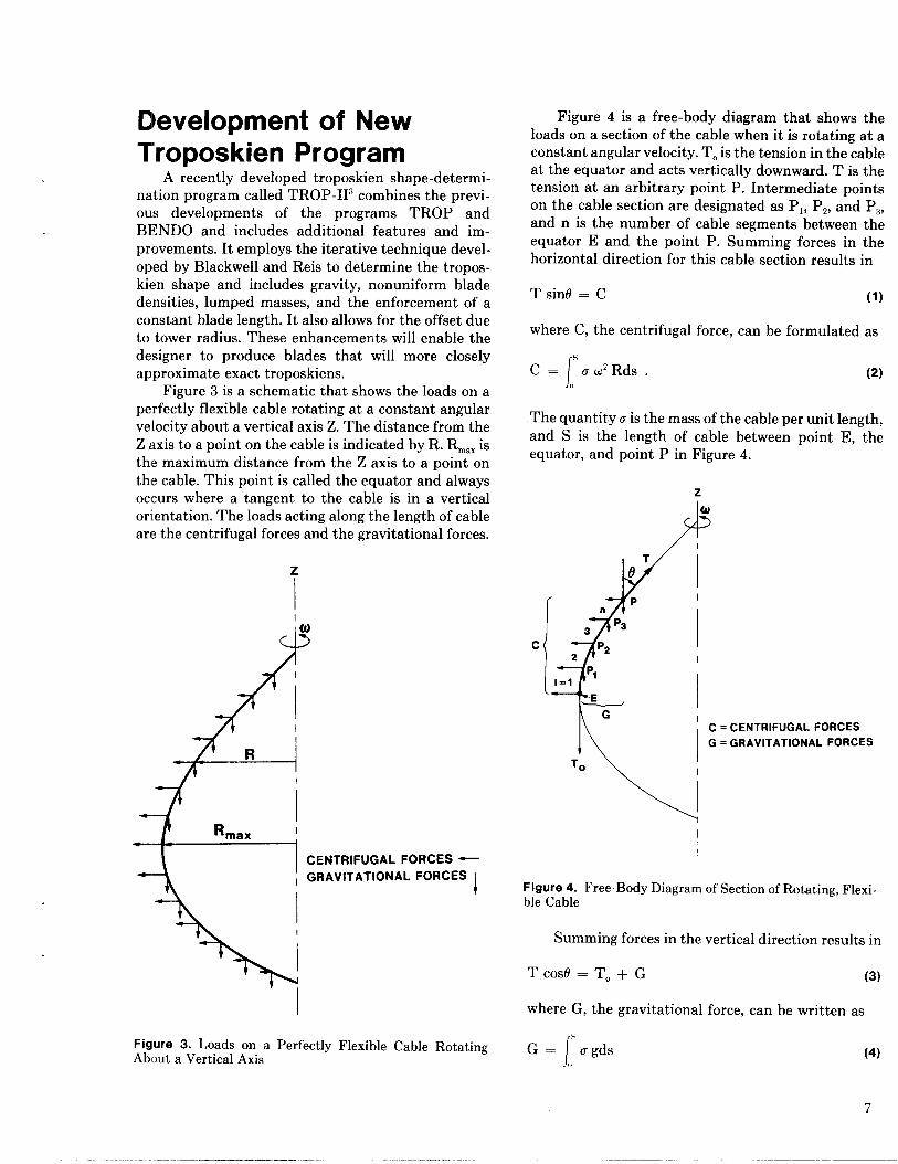
A recently developed troposkien shape-determi-nation program called TROP-113 combines the previ-ous developments of the programs TROP andBENDO and includes additional features and im-provements. It employs the iterative technique devel-oped by Blackwell and Reis to determine the tropos-kien shape and includes gravity, nonuniform bladedensities, lumped masses, and the enforcement of aconstant blade length. It also allows for the offset dueto tower radius. These enhancements will enable thedesigner to produce blades that will more closelyapproximate exact troposkiens.
Figure 3 is a schematic that shows the loads on aperfectly flexible cable rotating at a constant angularvelocity about a vertical axis Z. The distance from theZ axis to a point on the cable is indicated by R. R~.X isthe maximum distance from the Z axis to a point onthe cable. This point is called the equator and alwaysoccurs where a tangent to the cable is in a verticalorientation. The loads acting along the length of cableare the centrifugal forces and the gravitational forces.
I
II(0
&
.
CENTRIFUGAL FORCES —
GRAVITATIONAL FORCESi
I
I
Figure 3. Loads on a Perfectly Flexible Cable RotatingAbout a Vertical Axis
Figure 4 is a free-body diagram that shows theloads on a section of the cable when it is rotating at aconstant angular velocity. TOis the tension in the cableat the equator and acts vertically downward. T is thetension at an arbitrary point P. Intermediate pointson the cable section are designated as Pl, Pz, and P~,and n is the number of cable segments between theequator E and the point P. Summing forces in thehorizontal direction for this cable section results in
T sin/3 = C (1)
where C, the centrifugal force, can be formulated as
fC= ‘au2Rds. (2)
,,
The quantity u is the mass of the cable per unit length,and S is the length of cable between point E, theequator, and point P in Figure 4.
z
A
u
T
6
/[
Pn
P33
c P22
PI1=1
E
I
I
\
GC = CENTRIFUGAL FORCES
G = GRAVITATIONAL FORCES
To
IFigure 4. Free-Body Diagram of Section of Rotating, Flexi-ble Cable
Summing forces in the vertical direction results in
TCOS6=TO+G (3)
where G, the gravitational force, can be written as
fG= ‘ugds (4)
!)
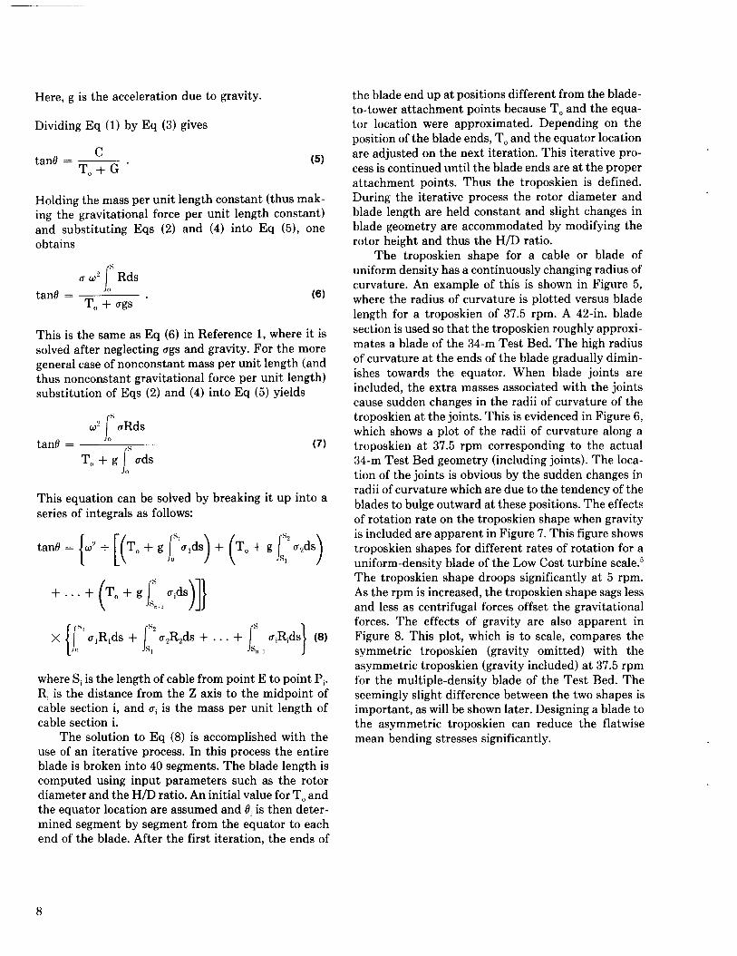
Here, g is the acceleration due to gravity.
Dividing Eq (1) by Eq (3) gives
tanf3 =c
(5)T,, +G”
Holding the mass per unit length constant (thus mak-ing the gravitational force per unit length constant)and substituting Eqs (2) and (4) into Eq (5), oneobtains
Jotantl =
TO + ags “(6)
This is the same as Eq (6) in Reference 1, where it issolved after neglecting ugs and gravity. For the moregeneral case of nonconstant mass per unit length (andthus nonconstant gravitational force per unit length)substitution of Eqs (2) and (4) into Eq (5) yields
\
s~? uRds
tan~ = “ s
/
(7)
To + g udso
This equation can be solved by breaking it up into aseries of integrals as follows:
‘ano=F2+[F0+gJ:”’ds)+F0+gr”2ds)+...+ro+gl:l,uds)]}]}
r ,s. r.s.. . . + /s uiRids] (8)
(Jo Js, JSn_, J
where Si is the length of cable from point E to point Pi.R, is the distance from the Z axis to the midpoint ofcable section i, and ai is the mass per unit length ofcable section i.
The solution to Eq (8) is accomplished with theuse of an iterative process. In this process the entireblade is broken into 40 segments. The blade length iscomputed using input parameters such as the rotordiameter and the H/D ratio. An initial value for TOandthe equator location are assumed and 0, is then deter-mined segment by segment from the equator to eachend of the blade. After the first iteration, the ends of
the blade end up at positions different from the blade-to-tower attachment points because TO and the equa-tor location were approximated. Depending on theposition of the blade ends, TOand the equator locationare adjusted on the next iteration. This iterative pro-cess is continued until the blade ends are at the properattachment points. Thus the troposkien is defined.During the iterative process the rotor diameter andblade length are held constant and slight changes inblade geometry are accommodated by modifying therotor height and thus the H/D ratio.
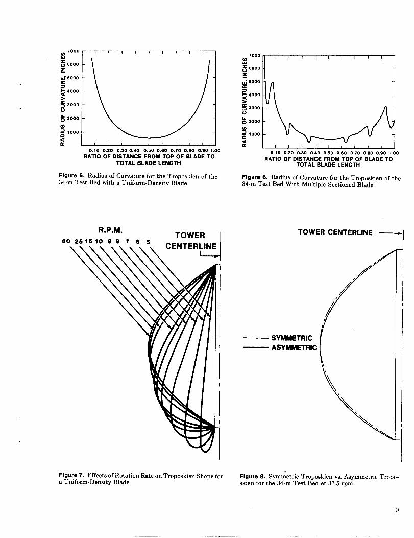
The troposkien shape for a cable or blade ofuniform density has a continuously changing radius ofcurvature. An example of this is shown in Figure 5,where the radius of curvature is plotted versus bladelength for a troposkien of 37.5 rpm. A 42-in. bladesection is used so that the troposkien roughly approxi-mates a blade of the 34-m Test Bed. The high radiusof curvature at the ends of the blade gradually dimin-ishes towards the equator. When blade joints areincluded, the extra masses associated with the jointscause sudden changes in the radii of curvature of thetroposkien at the joints. This is evidenced in Figure 6,which shows a plot of the radii of curvature along atroposkien at 37.5 rpm corresponding to the actual34-m Test Bed geometry (including joints). The loca-tion of the joints is obvious by the sudden changes inradii of curvature which are due to the tendency of theblades to bulge outward at these positions. The effectsof rotation rate on the troposkien shape when gravityis included are apparent in Figure 7. This figure showstroposkien shapes for different rates of rotation for auniform-density blade of the Low Cost turbine scale.5The troposkien shape droops significantly at 5 rpm.As the rpm is increased, the troposkien shape sags lessand less as centrifugal forces offset the gravitationalforces. The effects of gravity are also apparent inFigure 8. This plot, which is to scale, compares thesymmetric troposkien (gravity omitted) with theasymmetric troposkien (gravity included) at 37.5 rpmfor the multiple-density blade of the Test Bed. Theseemingly slight difference between the two shapes isimportant, as will be shown later. Designing a blade tothe asymmetric troposkien can reduce the flatwisemean bending stresses significantly.
U)7000 I I I I 1 1 I I 1 I
d 1 1 I I I I I I 1 1 1
0.10 0.20 0.300.40 0.50 0.60 0.70 0.80 0.90 1.00
RATIO OF DISTANCE FROM TOP OF BLADE TOTOTAL BLADE LENGTH
FigLlre5. Radius of Curvature forthe Troposkien of the34-m Test Bed with a Uniform-Density Blade
Figure 7. Effects of Rotation Rate on Troposkien Shape fora Uniform-Density Blade
t I I I I I I I I I
0.10 0.20 0.30 0.40 0.50 0.60 0.70 0.60 0.90 1.00
RATIO OF DISTANCE FROM TOP OF BLADE TOTOTAL BLADE LENGTH
Figure 6. Radius of Curvature for the Troposkien of the34-m Test Bed With Multiple-Sectioned Blade
—.—
TOWER CENTERLINE _
/
SYMMETRIC
ASYMMETRIC
Figure 8. Symmetric Troposkien vs. Asymmetric Tropo-skien for the 34-m Test Bed at 37.5 rpm
9
Design of Blade Shapes
Methods Used for Design ofExisting Blade Shapes
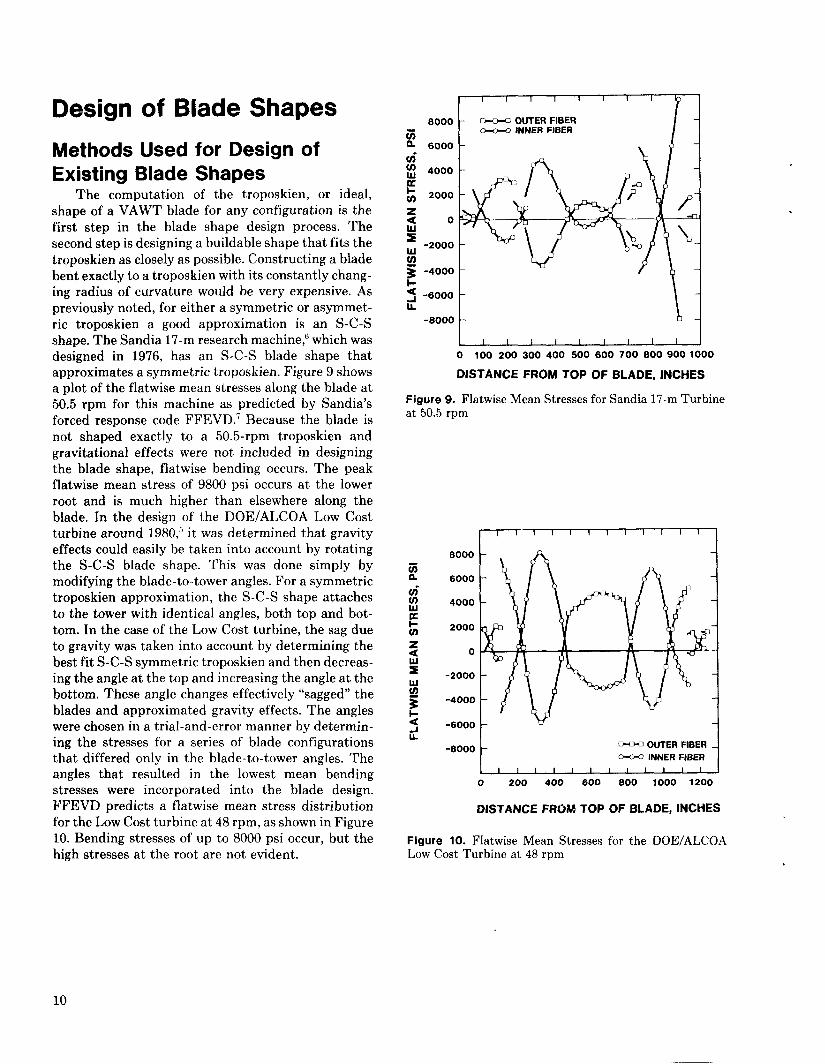
The computation of the troposkien, or ideal,shape of a VAWT blade for any configuration is thefirst step in the blade shape design process. Thesecond step is designing a buildable shape that fits thetroposkien as closely as possible. Constructing a bladebent exactly to a troposkien with its constantly chang-ing radius of curvature would be very expensive. Aspreviously noted, for either a symmetric or asymmet-ric troposkien a good approximation is an S-C-Sshape. The Sandia 17-m research machine,G which wasdesigned in 1976, has an S-C-S blade shape thatapproximates a symmetric troposkien. Figure 9 showsa plot of the flatwise mean stresses along the blade at50.5 rpm for this machine as predicted by Sandia’sforced response code FFEVD.T Because the blade isnot shaped exactly to a 50.5-rpm troposkien andgravitational effects were not included in designingthe blade shape, flatwise bending occurs. The peakflatwise mean stress of 9800 psi occurs at the lowerroot and is much higher than elsewhere along theblade. In the design of the DOE/ALCOA Low Costturbine around 1980,b it was determined that gravityeffects could easily be taken into account by rotatingthe S-C-S blade shape. This was done simply bymodifying the blade-to-tower angles. For a symmetrictroposkien approximation, the S-C-S shape attachesto the tower with identical angles, both top and bot-tom. In the case of the Low Cost turbine, the sag dueto gravity was taken into account by determining thebest fit S-C-S symmetric troposkien and then decreas-ing the angle at the top and increasing the angle at thebottom. These angle changes effectively “sagged” theblades and approximated gravity effects. The angleswere chosen in a trial-and-error manner by determin-ing the stresses for a series of blade configurationsthat differed only in the blade-to-tower angles. Theangles that resulted in the lowest mean bendingstresses were incorporated into the blade design.FFEVD predicts a flatwise mean stress distributionfor the Low Cost turbine at 48 rpm, as shown in Figure10. Bending stresses of up to 8000 psi occur, but thehigh stresses at the root are not evident.
8000
z& 6000”
i-
I I I I i I I I
~ OUTER FIBER~ INNER FIBER
~ -6000IL t Ii
-8000 b
I 1 I I I I I I I
0 100 200 300 400 500 600 700 8009001000
DISTANCE FROM TOP OF BLADE, INCHES
Figure 9. Flatwise Mean Stresses for Sandia 17-m Turbineat 50.5 rpm
I I I I I I I I I 1 I I I
ii
-6000— OUTER FIBER
~ INNER FIBER
I I I I I I I I I I I I
o 200 400 600 800 1000 1200
DISTANCE FROM TOP OF BLADE, INCHES
Figure 10. Flatwise Mean Stresses for the DOE/ALCOALow Cost Turbine at 48 rpm
10
Ne!w Blade-Shape DesignMethodology
A blade-shape design software package, TROP-FIT~ has been developed that incorporates the previ-ously discussed program TROP-11. This package al-lows the user to determine the troposkien shape for aparticular blade and then develop a buildable approx-imation to this shape. TROPFIT contains severaloptions that can be used in the troposkien approxima-tion. One can still use the S-C-S approximation orincorporate any or all of the following options.
I} Multiple radii of curvature along the blade“ Straight joint sections anywhere along the blade(t Slope discontinuities or “kinks” at the joints.
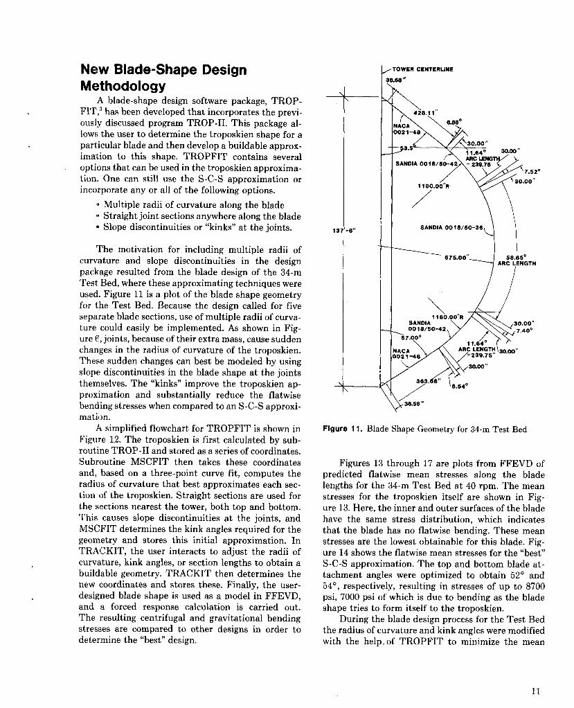
The motivation for including multiple radii ofcurvature and slope discontinuities in the designpackage resulted from the blade design of the 34-mTest Bed, where these approximating techniques wereused. Figure 11 is a plot of the blade shape geometryfor the Test Bed. Because the design called for fiveseparate blade sections, use of multiple radii of curva-ture could easily be implemented. As shown in Fig-ure 6,,joints, because of their extra mass, cause suddenchanges in the radius of curvature of the troposkien.These sudden changes can best be modeled by usingslope discontinuities in the blade shape at the jointsthemselves. The “kinks” improve the troposkien ap-proximation and substantially reduce the flatwisebending stresses when compared to an S-C-S approxi-mation,
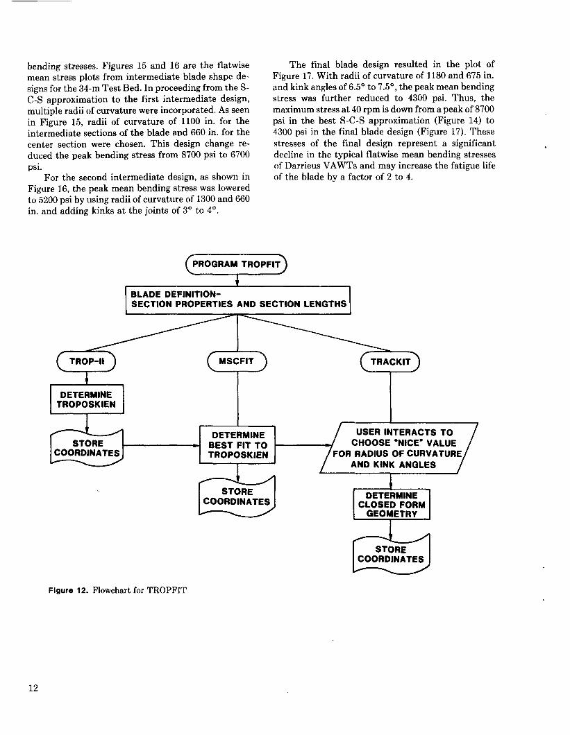
A simplified flowchart for TROPFIT is shown inFigure 12. The troposkien is first calculated by sub-routine TROP-11 and stored as a series of coordinates.Subroutine MSCFIT then takes these coordinatesand, based on a three-point curve fit, computes theradius of curvature that best approximates each sec-tion of the troposkien. Straight sections are used forthe sections nearest the tower, both top and bottom.This causes slope discontinuities at the joints, andMSCFIT determines the kink angles required for thegeometry and stores this initial approximation. InTRAICKIT, the user interacts to adjust the radii ofcurvature, kink angles, or section lengths to obtain abuildable geometry. TRACKIT then determines thenew coordinates and stores these. Finally, the user-designed blade shape is used as a model in FFEVD,and a forced response calculation is carried out.The resulting centrifugal and gravitational bendingstresses are compared to other designs in order todetermine the “best” design.
13 6“
, 10wER CENTERLINE
?&55 “
(IACA)02 1-48
33.56 /11.64” ‘m”
SANDIA 00 i 8150-42
“7
= 239.7S7.52”
Y
30.00”1180.00”R
/
+
SANOIA 001 S150-36
I675.00” 58.65°
ARC LENGTH
/
\1 lS0.00”R
SAM)IA00181 S0-42
\57.000
IACA021-48
/
/
/>
36.56 “
Figure 11. Blade Shape Geometry for 34-m Test Bed
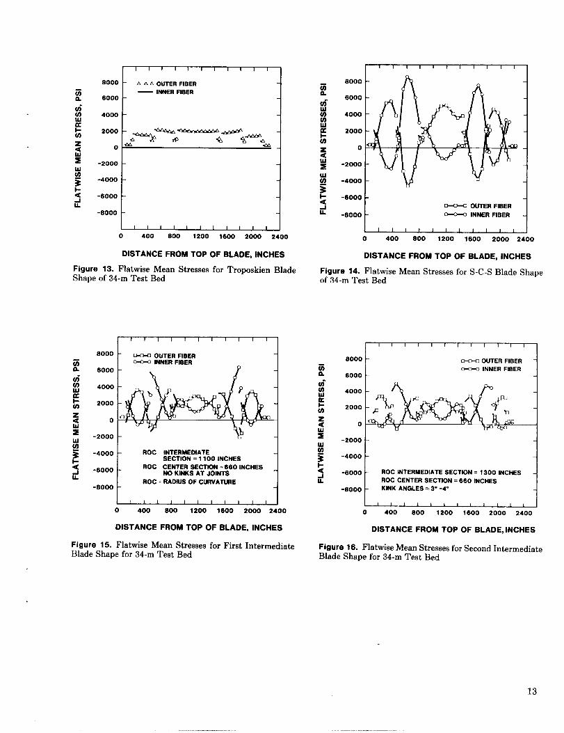
Figures 13 through 17 are plots from FFEVD ofpredicted flatwise mean stresses along the bladelengths for the 34-m Test Bed at 40 rpm. The meanstresses for the troposkien itself are shown in Fig-ure 13. Here, the inner and outer surfaces of the bladehave the same stress distribution, which indicatesthat the blade has no flatwise bending. These meanstresses are the lowest obtainable for this blade. Fig-ure 14 shows the flatwise mean stresses for the “best”S-C-S approximation. The top and bottom blade at-tachment angles were optimized to obtain 52° and54°, respectively, resulting in stresses of up to 8700psi, 7000 psi of which is due to bending as the bladeshape tries to form itself to the troposkien.
During the blade design process for the Test Bedthe radius of curvature and kink angles were modifiedwith the help. of TROPFIT to minimize the mean
——— ---
11
bending stresses. Figures 15 and 16 are the flatwisemean stress plots from intermediate blade shape de-signs for the 34-m Test Bed. In proceeding from the S-C-S approximation to the first intermediate design,multiple radii of curvature were incorporated. As seenin Figure 15, radii of curvature of 1100 in. for theintermediate sections of the blade and 660 in. for thecenter section were chosen. This design change re-duced the peak bending stress from 8700 psi to 6700psi.
For the second intermediate design, as shown inFigure 16, the peak mean bending stress was loweredto 5200 psi by using radii of curvature of 1300 and 660in. and adding kinks at the joints of 3° to 4°.
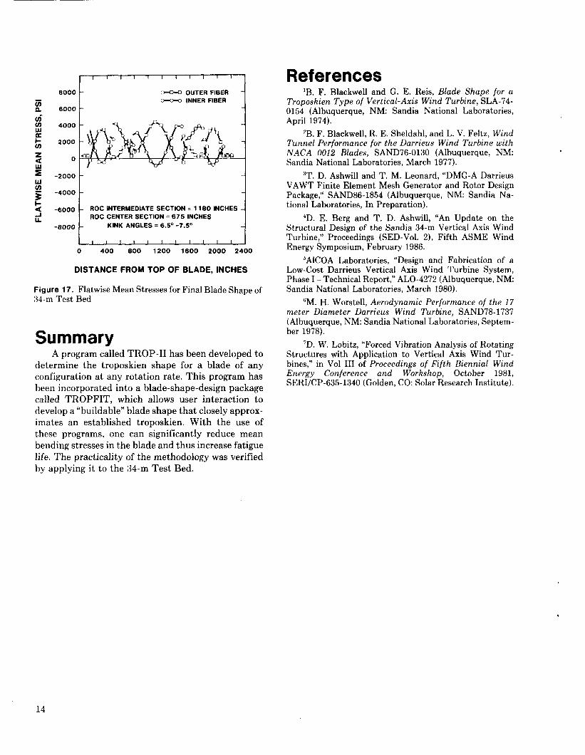
The final blade design resulted in the plot ofFigure 17. With radii of curvature of 1180 and 675 in.and kink angles of 6.5° to 7.5°, the peak mean bendingstress was further reduced to 4300 psi. Thus, themaximum stress at 40 rpm is down from a peak of 8700psi in the best S-C-S approximation (Figure 14) to43OO psi in the final blade design (Figure 17). Thesestresses of the final design represent a significantdecline in the typical flatwise mean bending stressesof Darrieus VAWTS and may increase the fatigue lifeof the blade by a factor of 2 to 4.
PROGRAM TROPFIT
+
BLADE DEFINITION-SECTION PROPERTIES AND SECTION LENGTHS
\
DETERMINETROPOSKIEN
DETERMINE USER INTERACTS TOSTORE CHOOSE “NICE” VALUE
COORDINATES TROPOSKIEN FOR RADIUS OF CURVATUREAND KINK ANGLES
STORECOORDINATES
DETERMINECLOSED FORM
GEOMETRY
.
dSTORECOORDINATES
Figure 12. Flowchart for TROPFIT
12
8000
6000
4000
2000
0
-2000
-4000
-6000
I I I I I I I I I 1 I
1A A A OUTER FIBER
— INNER FIBER 1
I I 1 1 1 I 1 I I I I
o 400 800 1200 1600 2000 2400
DISTANCE FROM TOP OF BLADE, INCHES
Figuro 13. Flatwise Mean Stresses for Troposkien BladeShape of 34-m Test Bed
8000
6000
U.1
4000
2000
0
-2000
I I I I I I I r 1 I I
~ OUTER FIBER~ INNER FIBER
g~ -4000
tROC INTERMEDIATE
SECTION =11 00 INCHES iz -6000
tROC CENTER SECTION= 660 INCHES
~ NO KINKS AT JOINTS -1L
1- ROC = RADIUS OF C1.RVAIWE-s000
IMIIIIU IIIo 400 600 1200 1600 2000 2400
DISTANCE FROM TOP OF BLADE, INCHES
Figure 15. Flatwise Mean Stresses for First IntermediateBlade Shape for 34-m Test Bed
u-1u.
I 1 I I I 1 1 I I I I I
8000
6000
4000
2000
0
-2000
-4000
-6000 I
t
~ OUTER FISER
-6000 ~ INNER FISERi
1 I I I I 1 I 1 I 1 1 t I
o 400 600 1200 1600 2000 2400
DISTANCE FROM TOP OF BLADE, INCHES
Figure 14. Flatwise Mean Stresses for S-C-S Blade ShaDe.–of 34-m Test Bed
Sooo
6000
4000
2000
0
-2000
-4000
-6000
I I I 1 I 1 I I 1 1 I 1
_ OUTER FISER~ INNER FIBER
1
ROC INTERMEDIATE SECTION= 1300 INCHESROC CENTER SECTION= 660 INCHES I
KINK ANGLES ==3“ -4°
1 1 I I 1 I 1 1 1 1 1 10 400 600 1200 1600 2000 2400
DISTANCE FROM TOP OF BLADE, INCHES
Figure 16. Flatwise Mean Stresses for Second IntermediateBlade Shape for 34-m Test Bed
13
.. . . .———.—
8000
za 6000
a-$ 4000
s(n
2000
z< 0
* -2000ulg
3-4000
1-a4
-6000
IA-8000
1 1 I I 1 1 ! I I I II
~ OUTER FIBER~ INNER FIBER i
1
ROC INTERMEDIATE SECTION = 11 BO INCHESROC CENTER SECTION = 675 INCHES
KINK ANGLES =6.5” -7.5”1
I I 1 I I I I I I I I I
o 400 800 1200 1600 2000 2400
DISTANCE FROM TOPOF BLADE, INCHES
Figure 17. Flatwise Mean Stresses for Final Blade Shape of34-m Test Bed
SummaryA program called TROP-II hasbeen developedto
determine the troposkien shape for a blade of anyconfiguration at any rotation rate. This program hasbeen incorporated into a blade-shape-design packagecalled TROPFIT, which allows user interaction todevelop a’’buildable” bladeshapethat closelyapprox-imates an established troposkien. With the use ofthese programs, one can significantly reduce meanbending stresses in the blade and thus increase fatiguelife. The practicality of the methodology was verifiedby applying it to the 34-m Test Bed.
References‘B. F. Blackwell and G. E. Reis, Blade Shape /or a
Troposkien Type of Vertical-Axis Wind Turbine, SLA-74-0154 (Albuquerque, NM: Sandia National Laboratories,April 1974).
‘B. F. Blackwell, R. E. Sheldahl, and L. V. Feltz, WindTunnel Performance for the Darrieus Wind Turbine withNACA 0012 Blades, SAND76-0130 (Albuquerque, NM:Sandia National Laboratories, March 1977).
3T. D. Ashwill and T. M. Leonard, “DMG-A DarrieusVAWT Finite Element Mesh Generator and Rotor DesignPackage; SAND86-1854 (Albuquerque, NM: Sandia Na-tional Laboratories, In Preparation).
‘D. E. Berg and T. D. Ashwill, “An Update on theStructural Design of the Sandia 34-m Vertical Axis WindTurbine,” Proceedings (SED-VO1. 2), Fifth ASME WindEnergy Symposium, February 1986.
5AICOA Laboratories, “Design and Fabrication of aLow-Cost Darrieus Vertical Axis Wind Turbine System,Phase I - Technical Report,” ALO-4272 (Albuquerque, NM:Sandia National Laboratories, March 1980).
‘M. H. Worstell, Aerodynamic Performance of the 17meter Diameter Darrieus Wind Turbine, SAND78-1737(Albuquerque, NM: Sandia National Laboratories, Septem-ber 1978).
7D. W. Lobitz, “Forced Vibration Analysis of RotatingStructures with Application to Vertical Axis Wind Tur-bines,” in Vol III of Proceedings of Fifth Biennial WindEnergy Conference and Workshop, October 1981,SERI/CP-635-1340 (Golden, CO: Solar Research Institute).
.
14
DISTRIBUTION:
Aluminum Company of America (5)Alcc}a Technical CenterAttn: D. K, Ai
J. T. HuangJ. R. JombockM. KlingensmithJ. L. Prohaska
Alcc]a Center, PA 15069
Alternative Sources of EnergyAttn: L. StoiakenMilaca, MN 56353
Amarillo CollegeAttn: E. GilmoreAmarillo, TX 79100
American Wind Energy Association1516 King StreetAlexandria, VA 22314
Arizona State UniversityUniversity LibraryAttn: M. E. BeecherTempe, AZ 85281
Dr. A. S. BarkerTrinity Western7600 Glover RoadLangley, BCCANADA V3A 4R9
Battelle Pacific Northwest LaboratoryAttn: L. WendellPo 130X999Richland, WA 99352
Bechtel Group, Inc.Attn: B. LessleyPO 130x 3965San Francisco, CA 94119
Dr. George BergelesDept. of Mechanical EngineeringNational Technical University42, F’atission StreetAthensGREECE
Bonneville Power AdministrationAttn: N. ButlerPO 130x 3621Portland, OR 97225
Burns & Roe, Inc.Attn: G. A. Fontana800 Kinderkamack RoadOradell, NJ 07649
Canadian Standards AssociationAttn: T. Watson178 Rexdale Blvd.Rexdale, Ontario, M9W 1R3CANADA
Mark ChappelDivision of EnergyNational Research Council of CanadaMontreal RoadOttawa, Ontario, KIA 0R6CANADA
Professor V. A. L. ChasteauSchool of EngineeringUniversity of AucklandPrivate BagAucklandNEW ZEALAND
Colorado State UniversityDept. of Civil EngineeringAttn: R. N. MeroneyFort Collins, CO 80521
Commonwealth Electric Co.Attn: D. W. DunhamBOX 368Vineyard Haven, MA 02568
Gale B. CurtisCurtis Associates3089 Oro Blanco DriveColorado Springs, CO 80917
M. M. Curvin11169 Loop RoadSoddy Daisy, TN 37379
Department of Economic Planningand Development
Attn: G. N. MonssonBarrett BuildingCheyenne, WY 82002
Otto de VriesNational Aerospace LaboratoryAnthony Fokkerweg 2Amsterdam 1017THE NETHERLANDS
15
——.— —.. ——.—..
DISTRIBUTION (Continued):
DOE/ALOAttn: G. P. TennysonAlbuquerque, NM 87115
DOE/ALOEnergy Technology Liaison OfficeAttn: Capt. J. L. Hanson, USAFNGDAlbuquerque, NM 87115
DOE Headquarters (20)Wind/Oceans Technologies DivisionAttn: D. F. Ancona (5)
P. R. Goldman (15)1000 Independence AvenueWashington, DC 20585
J. B. DragtNederlands Energy Research Foundation(E. C. N.)Physics DepartmentWesterduinweg 3 Petten (nh)THE NETHERLANDS
Dynergy Systems CorporationAttn: C. Fagundes821 West L StreetLos Banes, CA 93635
Dr. Norman E. Farb10705 Providence DriveVilla Park, CA 92667
Electric Power Research Institute (2)Attn: E. Demeo
F. Goodman3412 Hillview AvenuePalo Alto, CA 94304
Alcir de Faro OrlandoPontificia Universidade Catolica-PUC/RjMechanical Engineering DepartmentR. Marques de S. Vicente 225Rio de JaneiroBRAZIL
A. D. GarradGarrad Hasson10 Northampton SquareLondon ECIM 5PAUNITED KINGDOM
Gates LearjetMid-Continent AirportAttn: G. D. ParkPO Box 7707Wichita, KS 67277
H. GerardinMechanical Engineering DepartmentFaculty of Sciences and EngineeringUniversity Laval-Quebec, GIK 7P4CANADA
R. T. GriffithsUniversity College of SwanseaDept. of Mechanical EngineeringSingleton ParkSwansea, SA2 8PPUNITED KINGDOM
Helion, Inc.Attn: J. Park, PresidentBox 445Brownsville, CA 95919
FloWind Corporation (3)Attn: L. Schienbein
I. VasB. Im
1183 Quarry LanePleasanton, CA 94566
Indal Technologies, Inc. (2)Attn: D. Malcolm
C. Wood3570 Hawkestone RoadMississauga, OntarioCANADA L5C 2V8
Institut de Recherche d’Hydro-Quebec (2)Attn: Gaston Beaulieu
Bernard Masse1800, Montee Ste-JulieVarennes, Quebec, JOL 2P0CANADA
Iowa State UniversityAgricultural Engineering, Room 213Attn: L. H. SoderholmAmes, IA 50010
K. JacksonWest Wind IndustriesPO Box 1705Davis, CA 95617
16
DISI’RIBUTION (Continued):
M. JacksonMcAllister Financial1816 SummitW. Lafayette, IN 47906
Kaiser Aluminum and Chemical Sales, Inc.Attn: A. A. Hagman14200 Cottage Grove AvenueDolton, IL 60419
Kaiser Aluminum and Chemical Sales, Inc.Attn: D. D. Doerr6177 Sunol Blvd.PO BOX 877Pleasanton, CA 94566
Kansas State UniversityElectrical Engineering DepartmentAttn: Dr. G. L. JohnsonManhattan, KS 66506
R. E. KellandThe College of Trades and TechnologyPO Box 1693Prince Philip DriveSt. John’s, Newfoundland, AIC 5P7CANADA
KW Control Systems, Inc.Attn: R. H. KleinRD#4, Box 914CSouth Plank RoadMiddletown, NY 10940
Kalman Nagy LehoczkyCort Adelers GT. 300s10 2NORWAY
L. LiljidahlBuilding 005, Room 304Bare-WestBeltsville, MD 20705
One LjungstromFFA, The Aeronautical Research Inst.Box 1;1021S-1611.1 BrommaSWEDEN
Robert LynetteR. Lynette & Assoc., Inc.15921 SE 46th WayBellevue, WA 98006
Massachusetts Institute of Technology (2)Attn: Professor N. D. Ham
W. L. Harris, Aero/Astro Dept.77 Massachusetts AvenueCambridge, MA 02139
H, S. MatsudaComposite Materials LaboratoryPioneering R&D LaboratoriesToray Industries, Inc.Sonoyama, Otsu, ShigaJAPAN 520
G. M. McNerneyUS Wind Power160 Wheeler RoadBurlington, MA 01803
Michigan State UniversityDivision of Engineering ResearchAttn: O. KraussEast Lansing, MI 48825
Napier College of Commerce and TechnologyTutor Librarian, Technology FacultyColinton RoadEdinburgh, EH1O 5DTENGLAND
National Rural Electric Cooperative AssnAttn: Wilson Prichett, HI1800 Massachusetts Avenue NWWashington, DC 20036
Natural Power, Inc.Attn: Leander NicholsNew Boston, NH 03070
Northwestern UniversityDept. of Civil EngineeringAttn: R. A. ParmaleeEvanston, IL 60201
Ohio State UniversityAeronautical and Astronautical Dept.Attn: Professor G. Gregorek2070 Neil AvenueColumbus, OH 43210
17
- ———..—. —.—.—-- .-
DISTRIBUTION (Continued):
Oklahoma State UniversityMechanical Engineering Dept.Attn: D. K. McLaughlinStillwater, OK 76074
Oregon State UniversityMechanical Engineering Dept.Attn: R. E. WilsonCorvallis, OR 97331
Pacific Gas & ElectricAttn: T. Hillesland34OOCrow Canyon RoadSan Ramon, CA 94583
Ion ParaschivoiuDepartment of Mechanical EngineeringEcole PolytechniqueCP 6079Succursale AMontreal H3C 3A7CANADA
Riso National Laboratory (2)Attn: Troels Friis Pederson
Helge PetersenPostbox 49DK-4000 RoskildeDENMARK
Jacques PlanteHydro QuebecPlace Dupuis Ile etage855 est rue Ste-CatherineMontreal, Quebec, H2L 4P5CANADA
The Power Company, Inc.Attm A. A. NeddPO Box 221Genesee Depot, WI 53217
Power Technologies Inc.Attn: Eric N. HinrichsenPO BOX 1058Schenectady, NY 12301-1058
Public Service Co. of New HampshireAttn: D. L. C. Frederick1000 Elm StreetManchester, NH 03105
Public Service Company of New MexicoAttn: M. LechnerPO BOX 2267Albuquerque, NM 87103
RANN, Inc.Attn: A. J. Eggers, Jr.260 Sheridan Ave., Suite 414Palo Alto, CA 94306
The Resources AgencyDepartment of Water Resources
Energy DivisionAttn: R. G. FerreiraPO BOX 388Sacramento, CA 95802
Dr. R. Ganesh Rajagopalan, Asst. Prof.Aerospace Engineering DepartmentIowa State University404 Town Engineering Bldg.Ames, IA 50011
Reynolds Metals CompanyMill Products DivisionAttn: G. E. Lennox6601 West Broad StreetRichmond, VA 23261
R. G. RichardsAtlantic Wind Test SitePO BOX 189Tignish P. E. I., COB 2B0CANADA
A. RobbMemorial University of NewfoundlandFaculty of Engineering and Applied SciencesSt. John’s Newfoundland, AIC 5S7CANADA
Solar Energy Research InstituteAttn: R. W. Thresher1617 Cole BoulevardGolden, CO 80401
Dr. Ing. Hans RuscheweyhInstitut fur LeichbauTechnische Hochschule AachenWullnerstrasse 7FEDERAL REPUBLIC OF GERMANY
,
18
DISTRIBUTION (Continued):
Beatrice de Saint LouventEsti~blissement d’Etudes et de Recheerches
Meteorologigues77 Rue de Serves92106 Boulogne-Billancourt CedexFRANCE
Gwen SchreinerLibrarianNational Atomic MuseumAlbuquerque, NM 87185
Arni~nSeginerProfessor of AerodynamicsTechnion-Israel Institute of TechnologyDepartment of Aeronautical EngineeringHaifaISRAEL
Farrell Smith Seiler, EditorWind Energy AbstractsPO 130x 3870Bozeman, MT 59772-3870
David SharpeDept. of Aeronautical EngineeringQueen Mary CollegeMile End RoadLondon, El 4NSUNITED KINGDOM
Kent SmithInstituto Technologico Costa RicoApartado 159 CartagoCOSTA RICA
Bent SorensonRosk~lde University CenterEnergy Group, Bldg. 17.2IMFUFAPO BOX 260DK-400 RoskildeDEN:MARK
Peter SouthADECON32 Rivalda RoadWeston, Ontario, M9M 2M3CANADA
Southern California EdisonResearch & Development Dept., Room 497Attn: R. L. SchefflerPO BOX 800Rosemead, CA 91770
G. StaceyThe University of ReadingDepartment of EngineeringWhiteknights, Reading, RG6 2AYUNITED KINGDOM
Stanford UniversityDept. of Aeronautics and Astronautics
Mechanical EngineeringAttn: Holt AshleyStanford, CA 94305
Dr. Derek TaylorAlternative Energy GroupWalton HallOpen UniversityMilton Keynes, MK7 6AAUNITED KINGDOM
R. J. Templin (3)Low Speed Aerodynamics LaboratoryNRC-National Aeronautical EstablishmentMontreal RoadOttawa, Ontario, KIA 0R6CANADA
Texas Tech University (2)Mechanical Engineering Dept.Attn: J. W. OlerPO BOX 4289Lubbock, TX 79409
K. J. TouryanMariah Research6200 Plateau Dr.Englewood, CO 80111
Tulane UniversityDept. of Mechanical EngineeringAttn: R. G. WattsNew Orleans, LA 70018
Tumac Industries, Inc.Attn: J. R. McConnell650 Ford StreetColorado Springs, CO 80915
19
DISTRIBUTION (Continued):
J. M. TurnerTerrestrial Energy Technology Program OfficeEnergy Conversion BranchAerospace Power Division/Aero Propulsion LabAir Force Systems Command (AFSC)Wright-Patterson AFB, OH 45433
United Engineers and Constructors, Inc.Attn: A. J. KaralisPO BOX 8223Philadelphia, PA 19101
Universal Data SystemsAttn: C. W. Dodd5000 Bradford DriveHuntsville, AL 35805
University of CaliforniaInstitute of Geophysics and Planetary PhysicsAttn: Dr. P. J. BaumRiverside, CA 92521
University of ColoradoDept. of Aerospace Engineering SciencesAttn: J. D. Fock, Jr.Boulder, CO 80309
University of MassachusettsMechanical and Aerospace Engineering Dept.Attn: Dr. D. E. CromackAmherst, MA 01003
University of New MexicoNew Mexico Engineering Research InstituteAttn: G. G. LeighCampus PO Box 25Albuquerque, NM 87131
University of OklahomaAero Engineering DepartmentAttn: K. BergeyNorman, OK 73069
University of Sherbrooke (2)Faculty of Applied ScienceAttn: A. Laneville
P. VittecoqSherbrooke, Quebec, JIK 2R1CANADA
The University of TennesseeDept. of Electrical EngineeringAttn: T. W. ReddochKnoxville, TN 37916
USDA, Agricultural Research ServiceSouthwest Great Plains Research CenterAttn: Dr. R. N. ClarkBushland, TX 79012
Utah Power and Light Co.Attn: K. R. Rasmussen51 East Main StreetPO Box 277American Fork, UT 84003
W. A. VachonW. A. Vachon & AssociatesPO Box 149Manchester, MA 01944
VAWTPOWER, Inc.Attn: P. N. Vosburgh134 Rio Rancho DriveRio Rancho, NM 87124
Washington State UniversityDept. of Electrical EngineeringAttn: F. K. BechtelPullman, WA 99163
West Texas State UniversityGovernment Depository LibraryNumber 613Canyon, TX 79015
West Texas State UniversityDepartment of PhysicsAttn: V. NelsonPO BOX 248Canyon, TX 79016
West Virginia UniversityDept. of Aero EngineeringAttn: R. Walters1062 Kountz AvenueMorgantown, WV 26505
D. WestlindCentral Lincoln People’s Utility District2129 North Coast HighwayNewport, OR 97365-1795
Wichita State University (2)Aero Engineering DepartmentAttn: M. Snyder
W. WentzWichita, KS 67208
20
DISTRIBUTION (Continued):
Wind Power DigestAttn: Michael EvansPO Box 700Bascom, OH 44809
Wisconsin Division of State EnergyAttn: Wind Program Manager8th Floor101 South Webster StreetMadlison, WI 53702
15201521!15231524:1524:160C11612!1612163C1163625252542316CI3162600C1620Cl622CI6225,6225I6225I6225,6225,622516225,622562256225,6225I6225I7111754475448024.314131513154-1
D. J. McCloskeyR. C. Reuter, Jr.J. H. BiffleA. K. MillerD. W. LobitzR. G. ClemR. H. BraaschT. M. LeonardR. C. MaydewG. F. I-IomiczR. P. ClarkW. N. SullivanJ. E. Mitchell (15)P. S. WilsonE. H. BecknerV. L. DuganD. G. SchuelerH. M. Dodd (50)T. D. AshwillD. E. BergL. R. GalloP. C. KlimasD. S. OscarM. E. RalphD. C. RedaM. A. RumseyW. A. StephensonH. J. SutherlandM. H. WorstellJ. W. ReedT. G. CarrieJ. LaufferP. W. DeanC. M. Ostrander (5)W. L. Garner (3)C. H. Dalin (28)For DOE/OSTI (Unlimited Release)
21
———. —..