development of variable camber continuous trailing … development of variable camber continuous...
TRANSCRIPT
15ATC-0250
Development of Variable Camber Continuous Trailing EdgeFlap for Performance Adaptive Aeroelastic Wing
Nhan Nguyen, Upender KaulNASA Ames Research Center
Moffett Field, CA 94035Sonia Lebofsky, Eric Ting, Daniel Chaparro
Stinger Ghaffarian Technologies, Inc.NASA Ames Research Center
Moffett Field, CA 94035James Urnes
Boeing Research and TechnologySt. Louis, MO 63134
Abstract
This paper summarizes the recent development of anadaptive aeroelastic wing shaping control technologycalled variable camber continuous trailing edge flap(VCCTEF). As wing flexibility increases, aeroelasticinteractions with aerodynamic forces and momentsbecome an increasingly important consideration inaircraft design and aerodynamic performance. Fur-thermore, aeroelastic interactions with flight dynamicscan result in issues with vehicle stability and control.The initial VCCTEF concept was developed in 2010by NASA under a NASA Innovation Fund study enti-tled “Elastically Shaped Future Air Vehicle Concept,”which showed that highly flexible wing aerodynamicsurfaces can be elastically shaped in-flight by activecontrol of wing twist and bending deflection in orderto optimize the spanwise lift distribution for drag re-duction. A collaboration between NASA and BoeingResearch & Technology was subsequently funded byNASA from 2012 to 2014 to further develop the VC-CTEF concept.
This paper summarizes some of the key research ar-eas conducted by NASA during the collaboration withBoeing Research and Technology. These researchareas include VCCTEF design concepts, aerody-namic analysis of VCCTEF camber shapes, aerody-namic optimization of lift distribution for drag mini-mization, wind tunnel test results for cruise and high-lift configurations, flutter analysis and suppressioncontrol of flexible wing aircraft, and multi-objectiveflight control for adaptive aeroelastic wing shapingcontrol.
1 INTRODUCTION
Air vehicles are typically designed to maintain suffi-cient structural rigidity for safe load-carrying capac-ity. Modern engineered materials such as compos-ites have begun to appear in new airframe designthat can provide less structural rigidity while maintain-ing the same load-carrying capacity. An example oflight-weight airframe design is the Boeing 787 Dream-liner aircraft, which has highly flexible wing structuresin comparison to those in older-generation aircraft.As wing flexibility increases, aeroelastic interactionswith aerodynamic forces and moments become an in-creasingly important consideration in aircraft designand aerodynamic performance. Furthermore, aeroe-lastic interactions with flight dynamics can result in is-sues with vehicle stability and control. Modern air-craft such as the Boeing 787 have technologies tocompensate for adverse aeroelastic interactions withflight performance and dynamics. Airbus also beginsto deploy similar technologies called aerodynamic re-optimization on recent aircraft production.
To address the performance aspects of wing flexibil-ity in transport design, NASA developed an innovativewing shaping control concept called the variable cam-ber continuous trailing edge flap (VCCTEF) in 2010 ina NASA Innovation Fund study sponsored by NASAInnovative Partnerships Program Office [1, 2, 3]. Thisstudy, entitled “Elastically Shaped Future Air Vehi-cle Concept,” showed that highly flexible wing aero-dynamic surfaces can be elastically shaped in-flightby active control of wing twist and bending deflectionin order to optimize the local angle of attack of wingsections to improve aerodynamic efficiency through
1
https://ntrs.nasa.gov/search.jsp?R=20150023531 2018-06-11T01:06:16+00:00Z

drag reduction during cruise and enhanced lift perfor-mance during take-off and landing.
Subsequently, this study has been further investi-gated under three NASA projects since 2011: theSubsonic Fixed Wing (SFW) project in 2011, theFixed Wing (FW) project from 2012 to 2014, and cur-rently the Advanced Air Transport Technology (AATT)project since 2015. Boeing Research and Technol-ogy which collaborated with NASA in the 2010 studywas funded by NASA Fixed Wing Project to continuecollaboration with NASA under a two-phase study tofurther develop the VCCTEF concept. The Phase Istudy was performed during 2012 to revise the initialVCCTEF concept and develop actuation mechanisms[4]. The Phase II study was a two-year effort from2013 to 2014. The objectives of the Phase II studywere to conduct aeroelastic analysis and flutter sup-pression control as well as two wind tunnel tests of acruise configuration in 2013 and a high-lift configura-tion in 2014 in a low-speed wind tunnel at the Univer-sity of Washington Aeronautical Laboratory (UWAL)[5].
This paper summarizes some of the key research ar-eas conducted by NASA in collaboration with BoeingResearch and Technology and UWAL. These areasinclude VCCTEF design concepts, aerodynamic anal-ysis of VCCTEF camber shapes using RANS OVER-FLOW CFD tool, aerodynamic optimization of lift dis-tribution for drag minimization using a coupled FEMvortex-lattice aerodynamic framework with nonlineartransonic correction, flutter analysis and flutter sup-pression control of flexible wing aircraft, and multi-objective flight control for the VCCTEF.
2 VCCTEF CONCEPT
Aeroelastic deflection can affect aircraft aerodynam-ics. As an aircraft cruises, fuel is burned and the wingloading is reduced, thereby causing the wing shape tochange. The change in wing shape can cause a dragpenalty since the wing shape no longer retains its op-timal design shape. This particularly can be an im-portant issue for lightweight flexible airframes. Thus,aircraft with flexible wing structures can potentially be-come less fuel-efficient if there is no mechanism tocompensate for aeroelastic deflection.
The objective of wing shaping control is to restore thewing shape back to an optimal shape through flap andor slat deployments. However, the drag penalty dueto flap and slat deflections can negate any benefit at-tained from wing shaping control. The initial study in2010 explored the use of distributed conventional flapand slat systems for wing shaping control. In a con-
ventional flap design, individual flaps are actuated in-dependently. As a result, the trailing edge of a wingformed by the flap deflections is discontinuous. Thisdiscontinuity is a source of drag penalty as well asacoustic emissions. Aerodynamic calculations showthat the drag penalty due to the conventional flap sys-tem could be substantial [1]. One way to reduce thedrag penalty is to use a single flap surface over a widewing span. However, this would compromise the flexi-bility and effectiveness of wing shaping control. Thus,a new low-drag wing shaping control device was pro-posed in the initial study. This flap system is referredto as a variable camber continuous trailing edge flap(VCCTEF) system, as shown in Figures 1 to 3, whichappears to provide a significant drag reduction over aconventional flap system based on the initial study in2010 [1].
Figure 1: Planform of Variable Camber ContinuousTrailing Edge Flap Concept
The two main features of this flap concept are:
1. Variable camber - The flap chord is comprised ofthree chordwise segments of equal chord lengthas shown in Figure 2. These three flap seg-ments are actuated in unison when a flap deflec-tion command is given. Each flap segment is de-flected by an angle equal to one third of the com-manded flap deflection relative to each other. Forexample, for a commanded flap deflection of 12◦,flap segment 1 which is positioned next to thewing is deflected 4◦, flap segment 2 that followsflap segment 1 is deflected 8◦, and flap segment3 at the trailing edge is deflected by 12◦. This de-flection achieves a circular arc trailing edge cam-ber as follows:
f1 =fc3
(1)
f2 =2fc3
(2)
f3 = fc (3)
2

where fc is the commanded flap deflection.
Figure 2: Three-Segment Variable Camber Flap
The camber angle of the flap is the differencebetween between f3 and f1. Thus, the variablecamber angle χ = 2fc/3 is a function of the com-manded flap deflection. A cambered flap is moreeffective in producing lift than a straight plain flap.That is, it should produce higher lift-to-drag ra-tios (L/D). Other types of camber could also bespecified instead of a circular arc camber.
The variable camber flap generally producesabout the same downwash as a simple plain flapdeflected by the same angle, as seen in Figure 2.However, the normal surface area of the variablecamber flap exposed to the flow field is signifi-cantly reduced. Thus, the drag reduction benefitof the variable camber flap is realized since thepressure drag across the flap surface is reduceddue to less exposed normal surface area.
0 10 20 30 40 50 60
−0.2
0
0.2
0.4
0.6
0.8
BBL, ft
f/f c
Figure 3: Continuous Trailing Edge Flap Sections
2. Continuous trailing edge - The continuous trail-ing edge is comprised of 12 spanwise sectionsto form a continuous trailing edge, as shown inFigure 3, when the flap is deflected. This contin-uous trailing edge would eliminate vortices whichotherwise would have formed at the conventionalflap discontinuity at the trailing edge. By reduc-ing or eliminating vortex formation, viscous dragcould be reduced and acoustic emissions from
turbulence could be attenuated. The materialand design methodology used to fabricate thisflap system must be able to provide some degreeof structural compliance due to differential flapdeflections that each flap spanwise section wouldneed to maintain a continuous trailing edge. Thisfeature provides a further drag reduction benefitin addition to the variable camber chordwise flapsegmentation concept.
Figure 4 illustrates the VCCTEF installed on a trans-port aircraft.
The VCCTEF is envisioned to be a multi-functionalflight control surface capable of
• Aerodynamic re-optimization of the flexible wingto obtain changes in lift-to-drag ratios for cruisedrag reduction throughout the flight envelope
• High-lift performance for take-off and landing
• Aeroservoelastic control of aeroelastic wingmodes
• Load alleviation control for gust and maneuverloads
• Rigid-body flight control for pitch and roll
Figure 4: Transport Aircraft with Variable CamberContinuous Trailing Edge Flap
The Phase I study entitled “Development of VariableCamber Continuous Trailing Edge Flap System” [4]was conducted by Boeing Research and Technologyin 2011 under the SFW Project. This study built uponthe development of the VCCTEF system for NASAGeneric Transport Model (GTM) which is essentiallybased on the B757 airframe, employing light-weightshaped memory alloy (SMA) technology for actuationand three individual chordwise segments shaped toprovide a variable camber to the flap, as defined in theinitial study in 2010. The spanwise flap is divided into14 sections attached to the outer wing and 3 sections
3

attached to the inner wing. Each 24-inch section hasthree cambered flap segments that can be individuallycommanded. These cambered flaps are joined to thenext section by a flexible transition material installedwith the same shape as the camber and thus provid-ing continuous flaps throughout the wing span withno drag producing gaps [6]. This continuous trailingedge flap design combined with the flap camber re-sult in lower drag increase during flap deflections. Inaddition, it also offers a potential noise reduction ben-efit. This results in the ability to control the wing twistshape as a function of span, resulting in a changeto the wing twist to establish the best lift-to-drag ra-tio (L/D) at any aircraft gross weight or mission seg-ment. Current wing twist on commercial transportsis permanently set for one cruise configuration, usu-ally for a 50% loading or mid-point on the gross weightschedule. The VCCTEF offers different wing twist set-tings for each gross weight condition and also differ-ent settings for climb, cruise and descent, a major fac-tor in obtaining best L/D conditions.
The VCCTEF concept developed by Boeing Re-search and Technology in conjunction with NASA isillustrated in Figure 5.
Figure 5: Wing Configured with the Variable CamberContinuous Trailing Edge Flap
A major goal is to develop a light-weight flap con-trol system that has a significant weight advantageas compared to current flap screw-jack actuators.Hydraulic, electric and Shape Memory Alloy (SMA)torque rod actuation were evaluated with the resultthat the SMA actuation has the best weight advan-tage, as shown in Figure 6. Moreover, the use ofhinge line actuation eliminates the large and heavyexternal mounted actuators, and permits all actuatorsto be interior to the wing and flap mold lines, thus con-tributing to the overall drag reduction goal. SMA actu-ators can deliver large hinge moments, but generallymove at a slow rate. The outer wing flap uses the
full-span third camber segment as a roll command ef-fector and as a control device for suppressing aeroe-lastic wing structural dynamic modes, both requiringhigh rates which can be met by electric actuators [7].This is shown in Figure 7.
Figure 6: Weight Comparison between Shape Mem-ory Alloy Actuators and Electric Motor Actuators
Figure 7: Shape Memory Alloy Torque Rod and Elec-tric Drive Actuation for VCCTEF Control
The Phase II study entitled “Development of Vari-able Camber Continuous Trailing Edge Flap Systemfor B757 with a More Flexible Wing” which was con-ducted in 2012 under the FW Project to investigatethe effectiveness of the VCCTEF for transport aircraftwith increased wing flexibility [5]. In particular, thebaseline wing stiffness of the GTM is arbitrarily re-duced by 50% thereby doubling the wing flexibility.Aerodynamic optimization, flutter analysis, and flutter
4

suppression control were studied to assess the effectof the increased wing flexibility [8]. Another objectiveof the Phase II study is to conduct a trade study withan alternative VCCTEF design which employs fewerflap elements for weight savings. Figure 8 illustratethe alternative VCCTEF concept which reduces thenumber of cambered flap segments from three to twoand the number of spanwise section from 14 to 8 forthe outer wing. Each spanwise section is 50 inches inlength and are separated by 5-inch elastomer transi-tion material. As part of the Phase II study, two windtunnel tests were conducted in the UWAL to performinitial assessments of the VCCTEF for cruise drag re-duction as well as high-lift performance. The cruiseconfiguration test was conducted in 2013 [9, 10] andthe high-lift configuration test was conducted in 2014[11, 12].
Figure 8: Alternative VCCTEF Concept with FewerFlaps
3 2D CFD SIMULATIONS
As part of the trade study, a 2D airfoil CFD simula-tion is performed using RANS CFD code OVERFLOW[13]. The computational study examines flow over a2D airfoil with various camber shapes and number ofcamber segments. In particular, the following airfoilconfigurations are studied:
Table 1: Definition of VCCTEF Configurations
The deflection of a flap segment is specified as a rela-tive deflection in relation to the previous flap segment.Thus, the configuration VCCTEF123 denotes a con-
figuration whereby the deflection of flap segment 1 is1◦ relative to the fixed wing section, the deflection offlap segment 2 is 2◦ relative to flap segment 1 or 3◦
relative to the fixed wing section, and the deflectionof flap segment 3 is 3◦ relative to flap segment 2 or6◦ relative to the fixed wing section. Thus all the con-figurations have the same flap deflection of 6◦ at thetrailing edge flap segment relative to the fixed wingsection.
The 2D wing section is selected to be at the wingbreak station on the GTM wing and is normal to thewing leading edge to account for the wing sweep, asshown in Figure 9. The flow conditions are M∞ = 0.7which accounts for the leading edge sweep angle,Re = 9× 10⁶, and α = 0◦ − 5◦.
Figure 9: 2-D Section with VCCTEF for OVERFLOWSimulations
Figure 10: Drag Coefficient vs. Angle of Attack Com-puted by OVERFLOW
Figure 10 shows the drag coefficient as a functionof the angle of attack. At a given angle of attack,the plain flap configuration VCCTEF6 has the highestdrag and the parabolic-arc-camber or VCCTEF123configuration has the lowest drag. This is consistent
5

with the profile drag of the plain flap configuration VC-CTEF6 being the largest based on the flap projectedarea normal to the flow direction. Figure 11 showsthe lift coefficient as a function of the angle of attack.The plain flap configuration VCCTEF6 produces thelargest incremental lift while the converse is true withthe parabolic-arc-camber configuration VCCTEF123.The lift-to-drag ratios of the VCCTEF configurationsare plotted in Figure 12.
Figure 11: Lift Coefficient vs. Angle of Attack Com-puted by OVERFLOW
Figure 12: Lift-to-Drag Ratio Computed by OVER-FLOW
The plain flap configuration VCCTEF6 has the low-est lift-to-drag ratio which is also less than the base-line clean airfoil configuration. Both the circular-arc-camber configuration VCCTEF222 and the parabolic-arc-camber configuration VCCTEF123 have the high-est lift-to-drag ratios. This indicates that the circular-arc-camber VCCTEF is much more aerodynamicallyefficient than the plain flap in producing lift. The effectof number of cambered segments is also revealed inFigure 12. The two-segment circular-arc-camber con-figuration VCCTEF33 has lower lift-to-drag ratio thanthe corresponding three-segment circular-arc-camber
configuration VCCTEF222, but has higher lift-to-dragratio than the plain flap configuration VCCTEF6.
Assuming that the flow over the VCCTEF surfaces isentirely subsonic, then the downwash created by theVCCTEF deflection is expressed as
∆wi = V∞δi (4)
where ∆wi is the incremental downwash and δi is theabsolute deflection of the i-th flap segment of the VC-CTEF.
The slope of the camber line is related to the down-wash as
dzidx
= −∆wiV∞
= −δi (5)
Based on thin-wing aerodynamic theory, the incre-mental lift coefficient produced by the VCCTEF isevaluated by the integral transform with a potentialkernel function f (θ) = cos θ − 1 as
∆Cl =Clαπ
ˆ π
θ1
dz
dxf (θ) dθ
= −Clαπ
n∑i=1
ˆ θi+1
θi
δi (cos θ − 1) dθ (6)
where θi is the transformed coordinate of the hingeposition of the inner flap segment and
x =c
2(1− cos θ) (7)
This integral is evaluated as
∆Cl =
n∑i=1
Clα∂α
∂δiδi (8)
where Clα is the sectional lift curve slope and ∂α/∂δiis the angle of attack sensitivity or camber controlderivative due to the VCCTEF flap deflection whichis given by
∂α
∂δi=
cos−1 c∗ −√
1− c∗2π
∣∣∣∣∣c∗i+1
c∗i
(9)
with c∗i = 1 − 2xi/c, c is the airfoil chord, xi =c − (n+ 1− i) cf is the flap hinge position of the i-thflap segment, and cf is the flap chord of a camberedsegment.
Table 2 is the comparison between the incrementallift prediction by OVERFLOW and the theoretical in-cremental lift from Eq. (8)
6
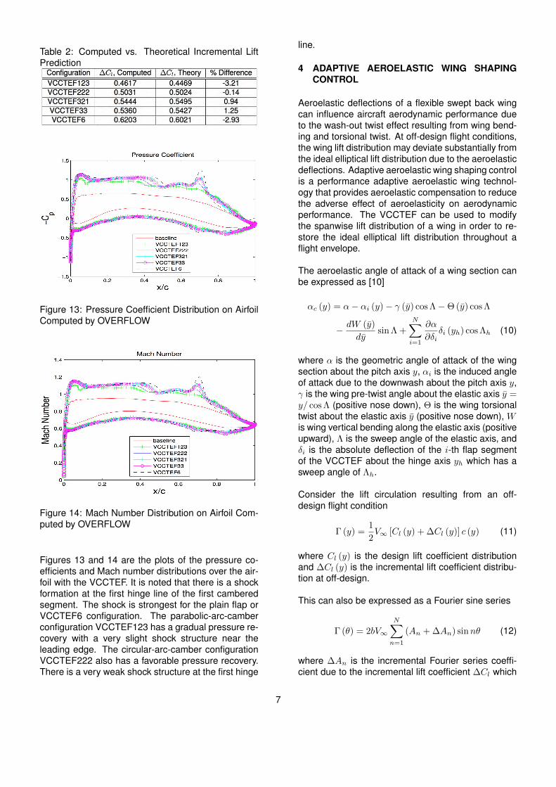
Table 2: Computed vs. Theoretical Incremental LiftPrediction
Figure 13: Pressure Coefficient Distribution on AirfoilComputed by OVERFLOW
Figure 14: Mach Number Distribution on Airfoil Com-puted by OVERFLOW
Figures 13 and 14 are the plots of the pressure co-efficients and Mach number distributions over the air-foil with the VCCTEF. It is noted that there is a shockformation at the first hinge line of the first camberedsegment. The shock is strongest for the plain flap orVCCTEF6 configuration. The parabolic-arc-camberconfiguration VCCTEF123 has a gradual pressure re-covery with a very slight shock structure near theleading edge. The circular-arc-camber configurationVCCTEF222 also has a favorable pressure recovery.There is a very weak shock structure at the first hinge
line.
4 ADAPTIVE AEROELASTIC WING SHAPINGCONTROL
Aeroelastic deflections of a flexible swept back wingcan influence aircraft aerodynamic performance dueto the wash-out twist effect resulting from wing bend-ing and torsional twist. At off-design flight conditions,the wing lift distribution may deviate substantially fromthe ideal elliptical lift distribution due to the aeroelasticdeflections. Adaptive aeroelastic wing shaping controlis a performance adaptive aeroelastic wing technol-ogy that provides aeroelastic compensation to reducethe adverse effect of aeroelasticity on aerodynamicperformance. The VCCTEF can be used to modifythe spanwise lift distribution of a wing in order to re-store the ideal elliptical lift distribution throughout aflight envelope.
The aeroelastic angle of attack of a wing section canbe expressed as [10]
αc (y) = α− αi (y)− γ (y) cos Λ−Θ (y) cos Λ
− dW (y)
dysin Λ +
N∑i=1
∂α
∂δiδi (yh) cos Λh (10)
where α is the geometric angle of attack of the wingsection about the pitch axis y, αi is the induced angleof attack due to the downwash about the pitch axis y,γ is the wing pre-twist angle about the elastic axis y =y/ cos Λ (positive nose down), Θ is the wing torsionaltwist about the elastic axis y (positive nose down), Wis wing vertical bending along the elastic axis (positiveupward), Λ is the sweep angle of the elastic axis, andδi is the absolute deflection of the i-th flap segmentof the VCCTEF about the hinge axis yh which has asweep angle of Λh.
Consider the lift circulation resulting from an off-design flight condition
Γ (y) =1
2V∞ [Cl (y) + ∆Cl (y)] c (y) (11)
where Cl (y) is the design lift coefficient distributionand ∆Cl (y) is the incremental lift coefficient distribu-tion at off-design.
This can also be expressed as a Fourier sine series
Γ (θ) = 2bV∞
N∑n=1
(An + ∆An) sinnθ (12)
where ∆An is the incremental Fourier series coeffi-cient due to the incremental lift coefficient ∆Cl which
7

is influenced by aeroelasticity according to
∆Cl (y) = Clα
[∆α− αi (y)−∆Θ (y) cos Λ
− d∆W (y)
dysin Λ +
N∑i=1
∂α
∂δi∆δi (yh) cos Λh
](13)
where ∆ denotes the change in the variable.
The wing lift coefficient is given by CL = A1πARwhere AR is the wing aspect ratio. Also, the wing in-cremental lift coefficient is given by ∆CL = ∆A1πAR.The induced drag is computed as
CDi = (A1 + ∆A1)2πAR×
×
[1 +
N∑n=2
n
(An + ∆AnA1 + ∆A1
)2]
=(CL + ∆CL)
2
πAR (e+ ∆e)
=(CL + ∆CL)
2
πARe+
2CL∆CLπARe1
+∆C2
L
πARe2(14)
where e is the design span efficiency factor, ∆e is theincremental span efficiency factor at off-design, ande1 and e2 are span efficiency factors associated with∆CL which are given by
1
e= 1 +
N∑n=2
n
(AnA1
)2
(15)
1
e1=
∞∑n=2
n
(AnA1
)(∆An∆A1
− AnA1
)(16)
1
e2=
N∑n=2
n
[(∆An∆A1
)2
−(AnA1
)2]
(17)
The contributions to the induced drag by the last twoterms in Eq. (14) represent the induced drag penalty,which can be minimized by the VCCTEF. If the in-duced drag penalty is ideally reduced to zero, thiswould result in
∆An =∆CLCL
An (18)
which can be used to determine the theoretical VC-CTEF deflections along the wing span to achieve thedesign span efficiency factor.
The analysis is intended to illustrate the induced dragpenalty due to the aeroelastic deflections. In practice,an aero-structural optimization study is conducted todetermine the optimal VCCTEF settings to achieve aminimum drag for the flexible wing GTM [14, 15, 16].An aeroelastic model is developed using a NASAvortex-lattice code, VORLAX, coupled with a finite-element model (FEM) code [17] and a 2D transonic
small disturbance code TSFOIL2 for transonic cor-rection [18]. Skin friction drag is added to partiallycorrect for viscous drag contribution. The modelingenvironment has an automated mesh generation ca-pability to modify the vortex-lattice mesh to accountfor aeroelastic deflections computed by the FEM codeand the VCCTEF settings determined by the opti-mizer [17, 19]. In addition, a higher-fidelity Euler CFDmodel is also developed for the optimization usingCART3D tool [20]. A RANS CFD capability is beingdeveloped to enable high-fidelity CFD assessmentswith full viscous effects in the near future.
The design cruise lift coefficient for the baseline GTMis selected to be 0.51 corresponding to a mid-cruisepoint with a gross weight of 210,000 lbs at Mach0.797 and altitude of 36,000 ft. The half-stiffnesswing GTM at the mid-cruise has a gross weight of204,636 lb. The weight reduction is attributed to thereduced structural weight of the wings. The mid-cruise point corresponds to a 50% fuel loading. Theoff-design cruise flight conditions include a beginningcruise condition at 80% fuel loading, an ending cruisecondition at 20% fuel loading, a high-altitude cruiseat 30% over the design cruise lift condition, and alow-altitude cruise at 30% under the design cruise liftcondition. The 30% over-design CL cruise conditionscorrespond to altitude of about 41,500 ft which couldexceed the aerodynamic ceiling since engine thrustrequirement is not accounted for.
Table 3: GTM Off-Design Cruise Conditions
A jig-shape twist optimization is performed for a wing-body GTM configuration at the design mid-cruise con-dition to attain an aerodynamically optimal jig-shapewing design corresponding to the baseline stiffnessand half stiffness wings. Figures 15 and 16 show thelift distributions with the jig-shape twist and optimizedtwist for the baseline stiffness wing and half stiffness
8

wing, respectively. The twist optimization results ina drag reduction of 0.00011 or 2.6% for the base-line stiffness wing and 0.00026 or 5.6% for the halfstiffness wing. The span load for the half stiffnesswing substantially deviates from the ideal elliptical liftdistribution, whereas the span load for the baselinestiffness wing more or less resembles the elliptical liftdistribution. Upon twist optimization, both span loadsfollow nearly the elliptical lift distribution particularly inthe outboard wing area.
Figure 15: Optimized Span Loads of Baseline Stiff-ness Wing at Mid-Cruise Condition Computed byCoupled VORLAX-FEM
Figure 16: Optimized Span Loads of Half StiffnessWing at Mid-Cruise Condition Computed by CoupledVORLAX-FEM
The wing-body GTM configurations for the baselinestiffness and half stiffness wings with the correspond-
ing optimized twists are then used for evaluating theeffectiveness of the VCCTEF at off-design cruise con-ditions. A drag optimization is conducted for the VC-CTEF layout as shown in Figure 9. The individual VC-CTEF deflection is described by a Chebyshev cubicpolynomial. Thus, the polynomial coefficients are thedesign variables in the drag optimization. A relativedeflection constraint of 2◦ is imposed on the deflec-tions of any two adjacent spanwise flap sections. Thechordwise flap segments are deflected in the circulararc fashion. The results for the drag optimization areshown in Table 4. The trend in the optimization re-sults indicates that the VCCTEF achieves more dragreduction as the cruise CL increases. For the 30%over-design CL cruise condition, a drag reduction ofmore than 4% is obtained from the optimization. Itis thought that the half stiffness wing is more flexible,therefore would allow more effective adaptive aeroe-lastic wing shaping control to achieve greater drag re-duction. However, this is not evident from the opti-mization results which indicate about the same per-centage drag reduction for the baseline stiffness wingand half stiffness wing.
Table 4: VCCTEF Drag Optimization Results Com-puted by Coupled VORLAX-FEM
Figures 17 and 18 show an optimized VCCTEF de-flection and the corresponding lift distribution for the30% over-design CL cruise condition. The absoluteflap deflection of the trailing edge flap segment rangesfrom 8◦ for flap section 1 at the wing root to 5◦ for flapsection 13 near the outboard wing area. The spanload for the half stiffness wing at 30% over-design CLcruise condition with the optimized VCCTEF does notfollow the elliptical lift distribution as well as the spanload for the clean wing with only optimized twist. Thisperhaps could be due to the fuselage-wing interfer-ence effect that causes the fuselage lift to decreasewhile the wing lift to increase as a result of the changein the trim angle of attack from 3.35◦ for the clean wing
9
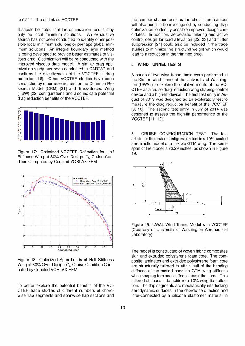
to 0.5◦ for the optimized VCCTEF.
It should be noted that the optimization results mayonly be local minimum solutions. An exhaustivesearch has not been conducted to identify other pos-sible local minimum solutions or perhaps global min-imum solutions. An integral boundary layer methodis being developed to provide better estimates of vis-cous drag. Optimization will be re-conducted with theimproved viscous drag model. A similar drag opti-mization study has been conducted in CART3D andconfirms the effectiveness of the VCCTEF in dragreduction [16]. Other VCCTEF studies have beenconducted by other researchers for the Common Re-search Model (CRM) [21] and Truss-Braced Wing(TBW) [22] configurations and also indicate potentialdrag reduction benefits of the VCCTEF.
Figure 17: Optimized VCCTEF Deflection for HalfStiffness Wing at 30% Over-Design CL Cruise Con-dition Computed by Coupled VORLAX-FEM
Figure 18: Optimized Span Loads of Half StiffnessWing at 30% Over-Design CL Cruise Condition Com-puted by Coupled VORLAX-FEM
To better explore the potential benefits of the VC-CTEF, trade studies of different numbers of chord-wise flap segments and spanwise flap sections and
the camber shapes besides the circular arc camberwill also need to be investigated by conducting dragoptimization to identify possible improved design can-didates. In addition, aeroelastic tailoring and activecontrol design for load alleviation [22, 23] and fluttersuppression [24] could also be included in the tradestudies to minimize the structural weight which wouldlead to a reduction in the trimmed drag.
5 WIND TUNNEL TESTS
A series of two wind tunnel tests were performed inthe Kirsten wind tunnel at the University of Washing-ton (UWAL) to explore the relative merits of the VC-CTEF as a cruise drag reduction wing shaping controldevice and a high-lift device. The first test entry in Au-gust of 2013 was designed as an exploratory test tomeasure the drag reduction benefit of the VCCTEF[9, 10]. The second test entry in July of 2014 wasdesigned to assess the high-lift performance of theVCCTEF [11, 12].
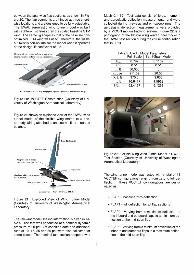
5.1 CRUISE CONFIGURATION TEST The testarticle for the cruise configuration test is a 10%-scaledaeroelastic model of a flexible GTM wing. The semi-span of the model is 73.29 inches, as shown in Figure19.
Figure 19: UWAL Wind Tunnel Model with VCCTEF(Courtesy of University of Washington AeronauticalLaboratory)
The model is constructed of woven fabric compositesskin and extruded polystyrene foam core. The com-posite laminates and extruded polystyrene foam coreare structurally tailored to attain half of the bendingstiffness of the scaled baseline GTM wing stiffnesswhile keeping torsional stiffness about the same. Thistailored stiffness is to achieve a 10% wing tip deflec-tion. The flap segments are mechanically interlockingaerodynamic surfaces in the chordwise direction andinter-connected by a silicone elastomer material in
10
between the spanwise flap sections, as shown in Fig-ure 20. The flap segments are hinged at three chord-wise locations and are designed to be fully adjustable.The UWAL aeroelastic wind tunnel model was builtwith a different stiffness than the scaled baseline GTMwing. The same jig shape as that of the baseline non-optimized GTM wing was used. Therefore, the wash-out twist is non-optimal for the model when it operatesat the design lift coefficient of 0.51.
Figure 20: VCCTEF Construction (Courtesy of Uni-versity of Washington Aeronautical Laboratory)
Figure 21 shows an exploded view of the UWAL windtunnel model of the flexible wing mated to a cen-ter body fairing attached to an external floor-mountedbalance.
Figure 21: Exploded View of Wind Tunnel Model(Courtesy of University of Washington AeronauticalLaboratory)
The relevant model scaling information is given in Ta-ble 5. The test was conducted at a nominal dynamicpressure of 20 psf. Off-condition data and additionalruns at 10, 15, 25 and 30 psf were also collected forsome cases. The nominal test section airspeed was
Mach 0.1162. Test data consist of force, moment,and aeroelastic deflection measurements, and werecollected during α-sweep and q∞-sweep runs. Theaeroelastic deflection measurements were providedby a VICON motion tracking system. Figure 22 is aphotograph of the flexible wing wind tunnel model inthe UWAL test section during the cruise configurationtest in 2013.
Table 5: UWAL Model ParametersFull-Scale Semi-Span Model
M∞ 0.797 0.1162CL 0.51 0.51h, ft 36,000 0
q∞, psf 211.09 20.00S/2, ft2 975.5 9.638c, ft 16.6417 1.5963b/2, ft 62.4167 6.1262
Figure 22: Flexible Wing Wind Tunnel Model in UWALTest Section (Courtesy of University of WashingtonAeronautical Laboratory)
The wind tunnel model was tested with a total of 13VCCTEF configurations ranging from zero to full de-flection. These VCCTEF configurations are desig-nated as:
• FLAP0 - baseline zero deflection
• FLAP1 - full deflection for all flap sections
• FLAP2 - varying from a maximum deflection atthe inboard and outboard flaps to a minimum de-flection at the mid-span flap
• FLAP3 - varying from a minimum deflection at theinboard and outboard flaps to a maximum deflec-tion at the mid-span flap
11

• FLAP4 - varying monotonically from a maximumdeflection at the inboard flap to zero deflection atthe outboard flap
• FLAP5 - varying monotonically from zero deflec-tion at the inboard flap to a maximum deflectionat the outboard flap
• FLAP6 - similar to FLAP4 configuration but witha smaller deflection
• FLAP7 - varying monotonically from a maximumpositive deflection at the inboard flap to a nega-tive deflection at the outboard flap
• FLAP8 - rigid-body deflection with the two outercamber segments at zero relative deflection
• FLAP9 - deflection of the trailing edge cambersegments
• FLAP10 - intermediate deflection
• FLAP11 - full negative deflection
• FLAP12 - FLAP6 configuration plus a gurney flap
Figure 23: Lift-to-Drag Ratios for Selected VCCTEFConfigurations in UWAL Cruise Configuration Test
Figure 23 is the plot of L/D for FLAP0, FLAP1,FLAP7, and FLAP11 configurations [10]. The base-line FLAP0 configuration has a L/D value of about16.1 at CL = 0.51. FLAP1 configuration has the high-est L/D at the same CL as compared to all the otherVCCTEF configurations. Its L/D is about 17.2 whichis about a 6.31% improvement. FLAP11 configurationis not aerodynamically efficient since it is configuredas a lift-reduction device with negative VCCTEF de-flections. Figure 24 shows the percentage drag re-duction for all the VCCTEF configurations. FLAP 1
configuration achieves the largest drag reduction with6.31% at the design cruise CL. All VCCTEF configu-rations except FLAP11 and FLAP12 achieve varyingdegree of drag reduction.
1 2 3 4 5 6 7 8 9 10 11 12−6
−4
−2
0
2
4
6
8
VCCTEF Configuration
% C
D R
eduction
Figure 24: Drag Reduction of VCCTEF Configura-tions in UWAL Cruise Configuration Test
Aeroelastic analysis shows that the lift coefficient ofa flexible wing at low dynamic pressure can be ex-pressed as a function of the angle of attack, dynamicpressure and aeroelastic deflections as [10]
CL = C∗L + (a0 + aαα+ aδδ) q∞
+ (b0 + bαα+ bδδ) q2∞ + (c0 + cαα+ cδδ) q
3∞ (19)
where C∗L is the rigid-wing lift coefficient and a(0,α,δ)
are negative for swept back wings.
Figure 25 shows the lift coefficient sensitivity to thedynamic pressure. As the dynamic pressure in-creases, the lift coefficient decreases. By extrapola-tion of the data to q∞ = 0, one can estimate the rigidwing lift coefficient. Both linear and cubic polynomialextrapolation were used to correct the flexible wing liftcurves to obtain the rigid wing lift curves. The cubicpolynomial method is supposed to yield more accu-rate estimates according to Eq. (19).
Aeroelastic deflection measurements were taken witha VICON motion tracking system. The VICON systemuses 54 optical targets, called dots, to create a three-dimensional displacement of the wind tunnel modelas it is loaded. The displacement measurements atthese dots are reduced to the spanwise out-of-planedeflections and twists at six spanwise locations, asshown in Figure 26. Figure 27 shows the measuredbending deflection about the elastic axis of FLAP0configuration. The wash-out twist about the pitch axis
12

due to bending slope is plotted in Figure 28. The flex-ibility results in a wash-out twist of 3.5◦ nose down atthe wing tip corresponding to an angle of attack of 6◦
for FLAP0 configuration. For comparison, the calcu-lated torsional twist about the elastic axis at the wingtip is less than 0.5◦, as shown in Figure 29. This in-dicates that the wing is much more flexible in bendingthan in torsion and that the wash-out twist effect isprimarily due to wing bending [10, 25].
Figure 25: FLAP0 Cubic and Linear Variations of CLwith q∞
Figure 26: VICON Target and Spanwise DeflectionMeasurement Locations
As an alternative approach, the rigid wing lift coef-ficient can be estimated from the static bending andtorsional deflections of the wing. The wing aeroelasticdeflection results in an effective change in the angle
of attack, which is computed as [10]
∆α = − 1
C∗LαS
ˆ b/2
−b/2c∗Lα (y)
[Θ (y) cos Λ
+dW (y)
dyw sin Λ
]c (y) dy (20)
where c∗Lα (y) is the sectional lift curve slope for therigid wing.
This effective change in the angle of attack is a func-tion of the angle of attack as
∆α = ∆α0 +∂∆α
∂αα (21)
By making an assumption that c∗Lα (y) = C∗Lα , therigid wing lift coefficient can be computed from theflexible wing lift coefficient as [10]
C∗L = CL −CLα∆α
1 + ∂∆α∂α
(22)
Figure 30 shows the rigid wing lift coefficients esti-mated by the aeroelastic deflection correction methodand the two q∞-correction methods as compared tothe flexible wing lift coefficient [10]. The aeroelasticdeflection correction method yields the highest esti-mated rigid-wing lift coefficient. Since there are somedifferences in the three estimated rigid wing lift coef-ficients, an average rigid wing lift coefficient is com-puted and is shown in Figure 30. The q∞-correctionmethod by a cubic extrapolation perhaps might bemore accurate than the aeroelastic deflection correc-tion method which depends on the assumption of con-stant spanwise sectional lift curve slope that may notbe realistic.
Figure 27: FLAP0 Bending Deflection
13
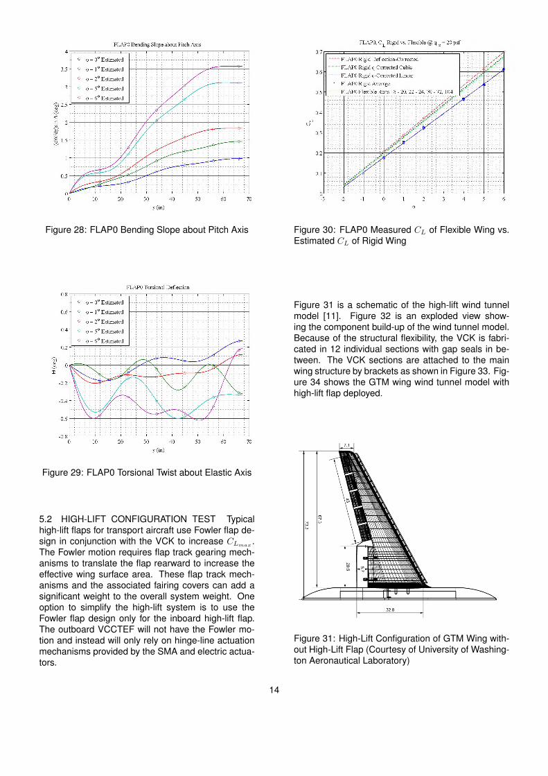
Figure 28: FLAP0 Bending Slope about Pitch Axis
Figure 29: FLAP0 Torsional Twist about Elastic Axis
5.2 HIGH-LIFT CONFIGURATION TEST Typicalhigh-lift flaps for transport aircraft use Fowler flap de-sign in conjunction with the VCK to increase CLmax .The Fowler motion requires flap track gearing mech-anisms to translate the flap rearward to increase theeffective wing surface area. These flap track mech-anisms and the associated fairing covers can add asignificant weight to the overall system weight. Oneoption to simplify the high-lift system is to use theFowler flap design only for the inboard high-lift flap.The outboard VCCTEF will not have the Fowler mo-tion and instead will only rely on hinge-line actuationmechanisms provided by the SMA and electric actua-tors.
Figure 30: FLAP0 Measured CL of Flexible Wing vs.Estimated CL of Rigid Wing
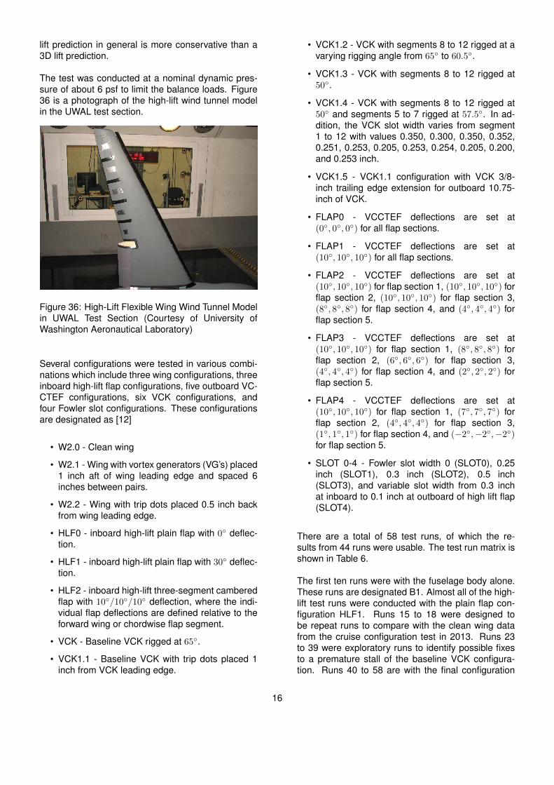
Figure 31 is a schematic of the high-lift wind tunnelmodel [11]. Figure 32 is an exploded view show-ing the component build-up of the wind tunnel model.Because of the structural flexibility, the VCK is fabri-cated in 12 individual sections with gap seals in be-tween. The VCK sections are attached to the mainwing structure by brackets as shown in Figure 33. Fig-ure 34 shows the GTM wing wind tunnel model withhigh-lift flap deployed.
Figure 31: High-Lift Configuration of GTM Wing with-out High-Lift Flap (Courtesy of University of Washing-ton Aeronautical Laboratory)
14
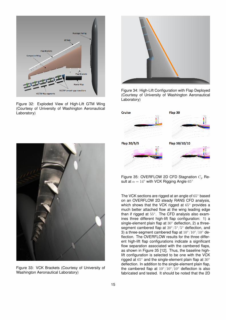
Figure 32: Exploded View of High-Lift GTM Wing(Courtesy of University of Washington AeronauticalLaboratory)
Figure 33: VCK Brackets (Courtesy of University ofWashington Aeronautical Laboratory)
Figure 34: High-Lift Configuration with Flap Deployed(Courtesy of University of Washington AeronauticalLaboratory)
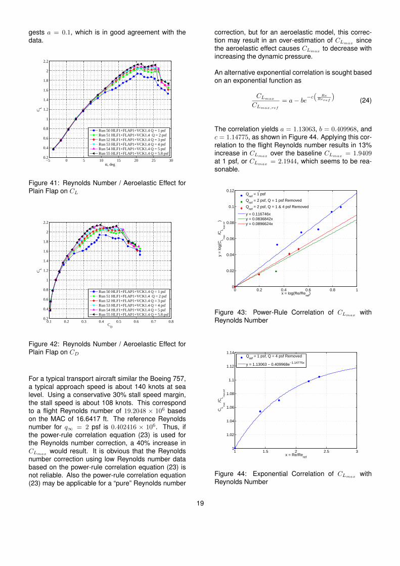
Figure 35: OVERFLOW 2D CFD Stagnation Cp Re-sult at α = 14◦ with VCK Rigging Angle 65◦
The VCK sections are rigged at an angle of 65◦ basedon an OVERFLOW 2D steady RANS CFD analysis,which shows that the VCK rigged at 65◦ provides amuch better attached flow at the wing leading edgethan if rigged at 55◦. The CFD analysis also exam-ines three different high-lift flap configuration: 1) asingle-element plain flap at 30◦ deflection, 2) a three-segment cambered flap at 20◦/5◦/5◦ deflection, and3) a three-segment cambered flap at 10◦/10◦/10◦ de-flection. The OVERFLOW results for the three differ-ent high-lift flap configurations indicate a significantflow separation associated with the cambered flaps,as shown in Figure 35 [12]. Thus, the baseline high-lift configuration is selected to be one with the VCKrigged at 65◦ and the single-element plain flap at 30◦
deflection. In addition to the single-element plain flap,the cambered flap at 10◦/10◦/10◦ deflection is alsofabricated and tested. It should be noted that the 2D
15
lift prediction in general is more conservative than a3D lift prediction.
The test was conducted at a nominal dynamic pres-sure of about 6 psf to limit the balance loads. Figure36 is a photograph of the high-lift wind tunnel modelin the UWAL test section.
Figure 36: High-Lift Flexible Wing Wind Tunnel Modelin UWAL Test Section (Courtesy of University ofWashington Aeronautical Laboratory)
Several configurations were tested in various combi-nations which include three wing configurations, threeinboard high-lift flap configurations, five outboard VC-CTEF configurations, six VCK configurations, andfour Fowler slot configurations. These configurationsare designated as [12]
• W2.0 - Clean wing
• W2.1 - Wing with vortex generators (VG’s) placed1 inch aft of wing leading edge and spaced 6inches between pairs.
• W2.2 - Wing with trip dots placed 0.5 inch backfrom wing leading edge.
• HLF0 - inboard high-lift plain flap with 0◦ deflec-tion.
• HLF1 - inboard high-lift plain flap with 30◦ deflec-tion.
• HLF2 - inboard high-lift three-segment camberedflap with 10◦/10◦/10◦ deflection, where the indi-vidual flap deflections are defined relative to theforward wing or chordwise flap segment.
• VCK - Baseline VCK rigged at 65◦.
• VCK1.1 - Baseline VCK with trip dots placed 1inch from VCK leading edge.
• VCK1.2 - VCK with segments 8 to 12 rigged at avarying rigging angle from 65◦ to 60.5◦.
• VCK1.3 - VCK with segments 8 to 12 rigged at50◦.
• VCK1.4 - VCK with segments 8 to 12 rigged at50◦ and segments 5 to 7 rigged at 57.5◦. In ad-dition, the VCK slot width varies from segment1 to 12 with values 0.350, 0.300, 0.350, 0.352,0.251, 0.253, 0.205, 0.253, 0.254, 0.205, 0.200,and 0.253 inch.
• VCK1.5 - VCK1.1 configuration with VCK 3/8-inch trailing edge extension for outboard 10.75-inch of VCK.
• FLAP0 - VCCTEF deflections are set at(0◦, 0◦, 0◦) for all flap sections.
• FLAP1 - VCCTEF deflections are set at(10◦, 10◦, 10◦) for all flap sections.
• FLAP2 - VCCTEF deflections are set at(10◦, 10◦, 10◦) for flap section 1, (10◦, 10◦, 10◦) forflap section 2, (10◦, 10◦, 10◦) for flap section 3,(8◦, 8◦, 8◦) for flap section 4, and (4◦, 4◦, 4◦) forflap section 5.
• FLAP3 - VCCTEF deflections are set at(10◦, 10◦, 10◦) for flap section 1, (8◦, 8◦, 8◦) forflap section 2, (6◦, 6◦, 6◦) for flap section 3,(4◦, 4◦, 4◦) for flap section 4, and (2◦, 2◦, 2◦) forflap section 5.
• FLAP4 - VCCTEF deflections are set at(10◦, 10◦, 10◦) for flap section 1, (7◦, 7◦, 7◦) forflap section 2, (4◦, 4◦, 4◦) for flap section 3,(1◦, 1◦, 1◦) for flap section 4, and (−2◦,−2◦,−2◦)for flap section 5.
• SLOT 0-4 - Fowler slot width 0 (SLOT0), 0.25inch (SLOT1), 0.3 inch (SLOT2), 0.5 inch(SLOT3), and variable slot width from 0.3 inchat inboard to 0.1 inch at outboard of high lift flap(SLOT4).
There are a total of 58 test runs, of which the re-sults from 44 runs were usable. The test run matrix isshown in Table 6.
The first ten runs were with the fuselage body alone.These runs are designated B1. Almost all of the high-lift test runs were conducted with the plain flap con-figuration HLF1. Runs 15 to 18 were designed tobe repeat runs to compare with the clean wing datafrom the cruise configuration test in 2013. Runs 23to 39 were exploratory runs to identify possible fixesto a premature stall of the baseline VCK configura-tion. Runs 40 to 58 are with the final configuration
16

with the VCK re-rigged to the proper rigging angles,designated as VCK1.4.
Table 6: UW2087 Test Run Matrix
Initial shakedown test runs were conducted to verifythe general lift characteristics of the high-lift wind tun-nel model. Indications of flow anomaly were noticedas the angle of attack increased. Premature stall wasnoted on the lift curve. Tufts were then installed onthe model for flow visualization which revealed aero-dynamic issues with premature flow separation at thewing outboard due to incorrect rigging of the VCK.Subsequently, angled shims were made to readjustthe VCK brackets [12]. The VCK inboard sections 1 to4 were kept at their original rigging angle of 65◦. TheVCK mid-sections 5 to 7 were readjusted to a riggingangle of 57.5◦. The VCK outboard sections 8 to 12were readjusted to a rigging angle of 50◦. By adjustingthe rigging angle of the VCK, high-lift aerodynamicsof the model significantly improved. Figure 37 showsthe lift curves for the clean wing with the VCK alonebefore and after the VCK rigging angle adjustment.Prior to the VCK rigging angle adjustment, the cleanwing configuration with the baseline VCK reaches astall angle of attack of 17◦ and a corresponding CL ofabout 1.2. After the VCK rigging angle adjustment tothe VCK1.4 configuration, the stall angle of attack in-creases to 22◦ corresponding to a CLmax of 1.7. Com-paring the baseline VCK and the VCK1.4 configura-tions, it is evident that the VCK adjustment was highlyeffective in eliminating the premature flow separationdue to the constant VCK rigging angle of 65◦ in thebaseline VCK configuration. This incorrect rigging isdue to the 2D CFD analysis of the inboard high-lift
flap that did not account for the different flow char-acteristics in the wing outboard area which could beinfluenced by a number of factors including the aeroe-lastic effect, the absence of the Fowler slot, and thepresence of the VCCTEF in lieu of the high-lift plainflap.
−10 −5 0 5 10 15 20 25 30 35 40−0.2
0
0.2
0.4
0.6
0.8
1
1.2
1.4
1.6
1.8
α, deg
CL
Run 15 Clean Wing Q = 5 psf
Run 26 VCK Q = 5.8 psf
Run 40 VCK1.4 Q = 5.8 psf
Figure 37: Lift Curve Before and After VCK RiggingAngle Adjustment
−10 −5 0 5 10 15 20 25 30−0.5
0
0.5
1
1.5
2
2.5
α, deg
CL
Run 39 HLF1+FLAP4+VCK1.4 Q = 5.8 psf
Run 40 HLF1+FLAP0+VCK1.4 Q = 5.8 psf
Run 15 Clean Wing Q = 5 psf
Figure 38: Lift Curves for Cruise Configuration,Cruise Configuration with VCK, and High-Lift Config-uration
Because the high-lift test was conducted at a fairlylow Reynolds number when a significant portion ofthe wing could be in the laminar boundary layer, tripdots were placed on the main wing very close to theleading edge in order to ensure fully turbulence flowover the main wing. Figure 38 shows the lift curves forthe clean wing cruise configuration, the cruise config-uration with the VCK deployed, and the high-lift con-figuration. The clean wing configuration achieves aCLmax of 1.05 at a stall angle of attack of 14◦. The
17

powerful effect of the VCK on the lift curve is noticedas the stall angle of attack increases from 14◦ to 22◦
which results in a CLmax of 1.7. With the VCK and theFowler plain flap deployed in a high-lift configuration,the stall angle of attack reduces to 19◦ correspond-ing to a CLmax of 2.1. The reduction in the stall angleof attack as the trailing edge flap is deployed is con-sistent with the high-lift aerodynamics. The high-liftCLmax of 2.1 is close to the desired CLmax for a typicalBoeing 757 landing configuration. Thus, the wind tun-nel test data confirms that the high-lift design for theVCCTEF is capable of providing high-lift performancefor transport aircraft [12].
−5 0 5 10 15 20 25 300.2
0.4
0.6
0.8
1
1.2
1.4
1.6
1.8
2
2.2
α, deg
CL
Run 45 HLF2+FLAP4+VCK1.4 Q = 5.8 psf
Run 42 HLF1+FLAP4+VCK1.4 Q = 5.8 psf
Figure 39: Lift Curves for Single-Element Plain Flapand Three-Segment Cambered Flap
−5 0 5 10 15 20 25 302
3
4
5
6
7
8
9
α, deg
L/D
Run 45 HLF2+FLAP4+VCK1.4 Q = 5.8 psf
Run 42 HLF1+FLAP4+VCK1.4 Q = 5.8 psf
Figure 40: L/D for Single-Element Plain Flap andThree-Segment Variable Camber Flap
Figure 39 shows the lift curves for the single-elementplain flap and the three-segment variable camber flap.The three-segment variable camber flap attains a
slight lower CLmax of 2.05 than that for the single-element plain flap. This reduction in lift is consistentwith the theoretical lift based on the potential flow the-ory discussed in Section 3. While the three-segmentcambered flap results in a slight lift reduction, it sig-nificantly improves aerodynamic efficiency or L/D byabout 6% over the single-element plain flap. Thisis shown in Figure 40. The wind tunnel test datathus confirms the drag reduction benefit of the three-segment cambered flap over the plain flap. Also, whilethe 2D OVERFLOW CFD predicts a significant flowseparation associated with the three-segment cam-bered flap, this is not evident in the 3D wind tunneltest data.
The Reynolds number / aeroelastic effect was also in-vestigated for both the plain flap and three-segmentcambered flap configurations. It should be noted that,because the flexible wing wind tunnel model is anaeroelastic model with a significant wing aeroelasticdeflection, there is really no “pure” Reynolds num-ber effect. As the dynamic pressure changes, boththe Reynolds number effect and aeroelastic effect acttogether to change lift. In general, CLmax increaseswith increasing the Reynolds number [26, 27] but de-creases with increasing the dynamic pressure for asweptback wing [10]. Figures 41 and 42 show thelift curves for the high-lift plain flap configuration ata varying dynamic pressure q∞ = 1 psf to 5.8 psf.As the dynamic pressure, hence Reynolds number,increases, the skin friction coefficient decreases fora fully turbulent boundary layer [28]. As a result,viscous drag generally decreases while lift increaseswith increasing Reynolds number. The wind tunneltest data indicate that the Reynolds number effectoutweighs the aeroelastic effect at stall. Otherwise,the trend of increasing CLmax with increasing the dy-namic pressure would have been reversed. There isa marked change in the lift and drag characteristics atα = 11◦ for q∞ = 1 psf, corresponding to a Reynoldsnumber per unit length of 0.17906× 10⁶/ft, possibly in-dicating of a flow separation. At a dynamic pressureabove 1 psf, the lift and drag characteristics appearsimilar.
Figure 43 shows a correlation of CLmax with theReynolds number based on a power-rule formula[26, 27]
CLmaxCLmax,ref
=
(Re
Reref
)a(23)
where Re is the Reynolds number based on the meanaerodynamic chord, and a is obtained from curve-fitting.
Using the data for q∞ = 2, 3, 5, and 5.8 psf, the cor-relation results in a = 0.0896624. Reference [27] sug-
18
gests a = 0.1, which is in good agreement with thedata.
−5 0 5 10 15 20 25 300.2
0.4
0.6
0.8
1
1.2
1.4
1.6
1.8
2
2.2
α, deg
CL
Run 50 HLF1+FLAP1+VCK1.4 Q = 1 psf
Run 51 HLF1+FLAP1+VCK1.4 Q = 2 psf
Run 52 HLF1+FLAP1+VCK1.4 Q = 3 psf
Run 53 HLF1+FLAP1+VCK1.4 Q = 4 psf
Run 54 HLF1+FLAP1+VCK1.4 Q = 5 psf
Run 55 HLF1+FLAP1+VCK1.4 Q = 5.8 psf
Figure 41: Reynolds Number / Aeroelastic Effect forPlain Flap on CL
0.1 0.2 0.3 0.4 0.5 0.6 0.7 0.80.2
0.4
0.6
0.8
1
1.2
1.4
1.6
1.8
2
2.2
CD
CL
Run 50 HLF1+FLAP1+VCK1.4 Q = 1 psf
Run 51 HLF1+FLAP1+VCK1.4 Q = 2 psf
Run 52 HLF1+FLAP1+VCK1.4 Q = 3 psf
Run 53 HLF1+FLAP1+VCK1.4 Q = 4 psf
Run 54 HLF1+FLAP1+VCK1.4 Q = 5 psf
Run 55 HLF1+FLAP1+VCK1.4 Q = 5.8 psf
Figure 42: Reynolds Number / Aeroelastic Effect forPlain Flap on CD
For a typical transport aircraft similar the Boeing 757,a typical approach speed is about 140 knots at sealevel. Using a conservative 30% stall speed margin,the stall speed is about 108 knots. This correspondto a flight Reynolds number of 19.2048 × 10⁶ basedon the MAC of 16.6417 ft. The reference Reynoldsnumber for q∞ = 2 psf is 0.402416 × 10⁶. Thus, ifthe power-rule correlation equation (23) is used forthe Reynolds number correction, a 40% increase inCLmax would result. It is obvious that the Reynoldsnumber correction using low Reynolds number databased on the power-rule correlation equation (23) isnot reliable. Also the power-rule correlation equation(23) may be applicable for a “pure” Reynolds number
correction, but for an aeroelastic model, this correc-tion may result in an over-estimation of CLmax sincethe aeroelastic effect causes CLmax to decrease withincreasing the dynamic pressure.
An alternative exponential correlation is sought basedon an exponential function as
CLmaxCLmax,ref
= a− be−c(
ReReref
)(24)
The correlation yields a = 1.13063, b = 0.409968, andc = 1.14775, as shown in Figure 44. Applying this cor-relation to the flight Reynolds number results in 13%increase in CLmax over the baseline CLmax = 1.9409at 1 psf, or CLmax = 2.1944, which seems to be rea-sonable.
0 0.2 0.4 0.6 0.8 10
0.02
0.04
0.06
0.08
0.1
0.12
x = log(Re/Reref
)
y =
log(C
Lm
ax
/CL
max,r
ef)
Q
ref = 1 psf
Qref
= 2 psf, Q = 1 psf Removed
Qref
= 2 psf, Q = 1 & 4 psf Removed
y = 0.116746x
y = 0.0836842x
y = 0.0896624x
Figure 43: Power-Rule Correlation of CLmax withReynolds Number
1 1.5 2 2.5 31
1.02
1.04
1.06
1.08
1.1
1.12
1.14
x = Re/Reref
CL
max
/CL
max,r
ef
Q
ref = 1 psf, Q = 4 psf Removed
y = 1.13063 − 0.409968e−1.14775x
Figure 44: Exponential Correlation of CLmax withReynolds Number
19
To correct for the Mach number effect, one can usethe Prandtl-Glauert subsonic compressibility correc-tion. This is only an approximate method since theflow at stall is nonlinear whereas the Prandtl-Glauertsubsonic compressibility correction is applicable tolinear subsonic flow. The Mach number correctionfactor also includes the effect of wing sweep. Thus
CLmaxCLmax,ref
=
√1−M2
∞,ref cos2 Λ
1−M2∞ cos2 Λ
(25)
where Λ is the sweep angle of the wing leading edge.
The stall speed is about Mach 0.16 whereas the ref-erence speed is about Mach 0.03. For a sweep angleΛ = 28◦, the Mach number correction results in 1%increase in CLmax or CLmax = 2.2169 for the high-liftplain flap. Similar corrections for the Reynolds andMach number effects are computed for the high-liftthree-segment cambered flap and result in CLmax =2.1927 [12].
It should be noted that the CLmax correlation is for awing with no engine nacelle and no horizontal tail. So,the CLmaxestimate may not directly translate into aCLmax for a complete aircraft configuration. Nonethe-less, this CLmax correlation can serve as a guide in thedesign of a high-lift system for a flexible wing transportsimilar to the high-lift configuration tested.
6 FLUTTER ANALYSIS AND SUPPRESSIONCONTROL
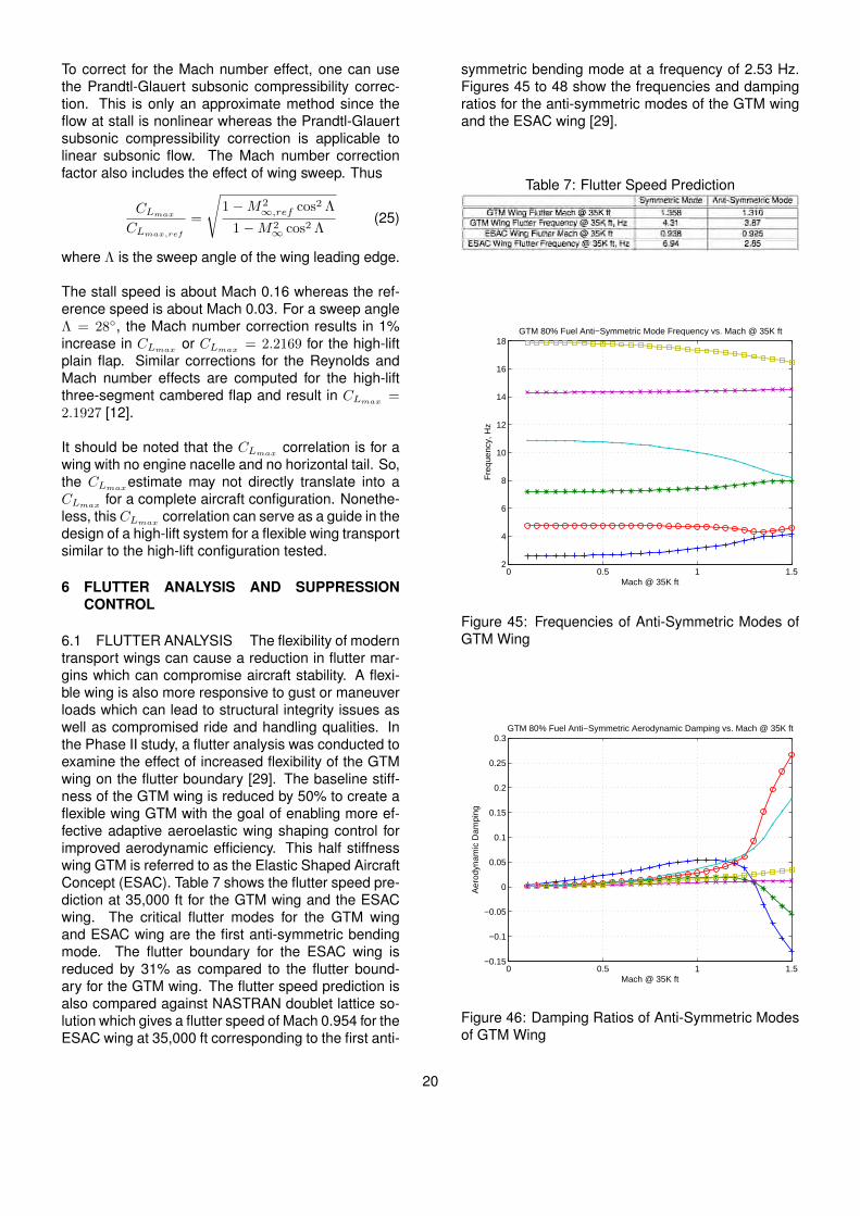
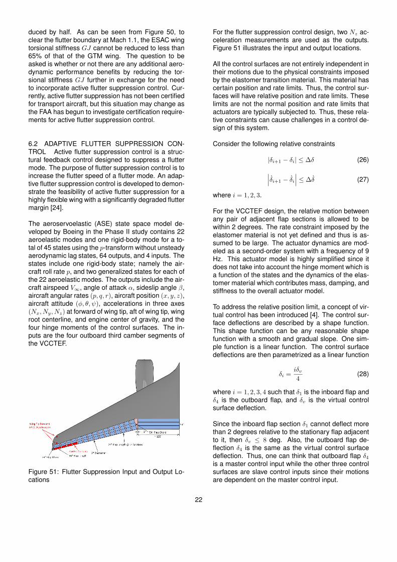
6.1 FLUTTER ANALYSIS The flexibility of moderntransport wings can cause a reduction in flutter mar-gins which can compromise aircraft stability. A flexi-ble wing is also more responsive to gust or maneuverloads which can lead to structural integrity issues aswell as compromised ride and handling qualities. Inthe Phase II study, a flutter analysis was conducted toexamine the effect of increased flexibility of the GTMwing on the flutter boundary [29]. The baseline stiff-ness of the GTM wing is reduced by 50% to create aflexible wing GTM with the goal of enabling more ef-fective adaptive aeroelastic wing shaping control forimproved aerodynamic efficiency. This half stiffnesswing GTM is referred to as the Elastic Shaped AircraftConcept (ESAC). Table 7 shows the flutter speed pre-diction at 35,000 ft for the GTM wing and the ESACwing. The critical flutter modes for the GTM wingand ESAC wing are the first anti-symmetric bendingmode. The flutter boundary for the ESAC wing isreduced by 31% as compared to the flutter bound-ary for the GTM wing. The flutter speed prediction isalso compared against NASTRAN doublet lattice so-lution which gives a flutter speed of Mach 0.954 for theESAC wing at 35,000 ft corresponding to the first anti-
symmetric bending mode at a frequency of 2.53 Hz.Figures 45 to 48 show the frequencies and dampingratios for the anti-symmetric modes of the GTM wingand the ESAC wing [29].
Table 7: Flutter Speed Prediction
0 0.5 1 1.52
4
6
8
10
12
14
16
18
GTM 80% Fuel Anti−Symmetric Mode Frequency vs. Mach @ 35K ft
Mach @ 35K ft
Fre
qu
ency, H
z
Figure 45: Frequencies of Anti-Symmetric Modes ofGTM Wing
0 0.5 1 1.5−0.15
−0.1
−0.05
0
0.05
0.1
0.15
0.2
0.25
0.3
Mach @ 35K ft
Ae
rodyn
am
ic D
am
pin
g
GTM 80% Fuel Anti−Symmetric Aerodynamic Damping vs. Mach @ 35K ft
Figure 46: Damping Ratios of Anti-Symmetric Modesof GTM Wing
20

0 0.5 1 1.50
2
4
6
8
10
12
14
ESAC 80% Fuel Anti−Symmetric Mode Frequency vs. Mach @ 35K ft
Mach @ 35K ft
Fre
qu
ency, H
z
Figure 47: Frequencies of Anti-Symmetric Modes ofESAC Wing
0 0.5 1 1.5−0.4
−0.2
0
0.2
0.4
0.6
0.8
1
ESAC 80% Fuel Anti−Symmetric Mode Aerodynamic Damping vs. Mach @ 35K ft
Mach @ 35K ft
Aero
dynam
ic D
am
pin
g
Figure 48: Damping Ratios of Anti-Symmetric Modesof ESAC Wing
A sensitivity study is conducted to determine the flut-ter boundary as a function of the ESAC wing torsionalstiffness GJ while the ESAC wing bending stiffnessEI is kept at half of that of the GTM wing. Figure 49shows the flutter boundary for a varying torsional stiff-ness from 100% to 50% of that of the GTM wing. Itcan be seen that the flutter boundary is highly sensi-tive to the torsional stiffness. As GJ increases, theflutter boundary also increases. When GJ is at 100%of that of the GTM wing, the flutter speed of mode1B is as high as that of the GTM wing. It should benoted that the bending stiffness is greater than thetorsional stiffness for the GTM wing by a factor of al-most 2:1. Therefore, if the torsional stiffness of theESAC wing is kept the same as that of the GTM wing,
then the bending stiffness and the torsional stiffnessof the ESAC wing are about the same. This studyshows that reducing the wing bending stiffness by nomore than half while keeping the torsional stiffnessthe same as the conventional wing stiffness does notseem to significantly degrade the flutter boundary.
0.4 0.6 0.8 1 1.2 1.4 1.60
0.5
1
1.5
2
2.5
3
3.5x 10
4
Anti−Symmetric 1B Flutter Mach
Altitu
de, ft
50% GJ
60% GJ
70% GJ
80% GJ
90% GJ
100% GJ
Figure 49: Flutter Boundary of ESAC Wing as a Func-tion of GJ
0.5 0.6 0.7 0.8 0.9 10.9
1
1.1
1.2
1.3
1.4
1.5
1.6
GJ Ratio @ 50% EI
Flu
tter
Ma
ch @
35K
ft
Flutter Mach Variation of ESAC Wings w/ GJ Variation
ASE Control
Dive Mach
Flutter Mach FAA Certification
GTM Flutter Mach
Figure 50: Flutter Speed Clearance of ESAC Wing
The FAA certification requires aircraft to demonstratea flutter margin of at least 15% above the dive speedwhich is normally determined from flight testing. Fora maximum operating Mach 0.8, the dive speed mightbe estimated at 20% over the maximum operatingMach. Thus, the flutter clearance would require theminimum flutter speed of at least Mach 1.1 at 35,000ft. The GTM wing meets this flutter clearance but theESAC wing does not if the torsional stiffness is re-
21
duced by half. As can be seen from Figure 50, toclear the flutter boundary at Mach 1.1, the ESAC wingtorsional stiffness GJ cannot be reduced to less than65% of that of the GTM wing. The question to beasked is whether or not there are any additional aero-dynamic performance benefits by reducing the tor-sional stiffness GJ further in exchange for the needto incorporate active flutter suppression control. Cur-rently, active flutter suppression has not been certifiedfor transport aircraft, but this situation may change asthe FAA has begun to investigate certification require-ments for active flutter suppression control.
6.2 ADAPTIVE FLUTTER SUPPRESSION CON-TROL Active flutter suppression control is a struc-tural feedback control designed to suppress a fluttermode. The purpose of flutter suppression control is toincrease the flutter speed of a flutter mode. An adap-tive flutter suppression control is developed to demon-strate the feasibility of active flutter suppression for ahighly flexible wing with a significantly degraded fluttermargin [24].
The aeroservoelastic (ASE) state space model de-veloped by Boeing in the Phase II study contains 22aeroelastic modes and one rigid-body mode for a to-tal of 45 states using the p-transform without unsteadyaerodynamic lag states, 64 outputs, and 4 inputs. Thestates include one rigid-body state; namely the air-craft roll rate p, and two generalized states for each ofthe 22 aeroelastic modes. The outputs include the air-craft airspeed V∞, angle of attack α, sideslip angle β,aircraft angular rates (p, q, r), aircraft position (x, y, z),aircraft attitude (φ, θ, ψ), accelerations in three axes(Nx, Ny, Nz) at forward of wing tip, aft of wing tip, wingroot centerline, and engine center of gravity, and thefour hinge moments of the control surfaces. The in-puts are the four outboard third camber segments ofthe VCCTEF.
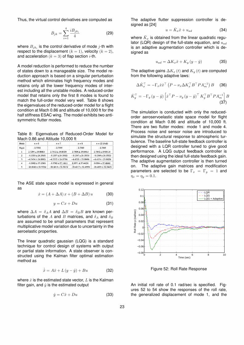
Figure 51: Flutter Suppression Input and Output Lo-cations
For the flutter suppression control design, two Nz ac-celeration measurements are used as the outputs.Figure 51 illustrates the input and output locations.
All the control surfaces are not entirely independent intheir motions due to the physical constraints imposedby the elastomer transition material. This material hascertain position and rate limits. Thus, the control sur-faces will have relative position and rate limits. Theselimits are not the normal position and rate limits thatactuators are typically subjected to. Thus, these rela-tive constraints can cause challenges in a control de-sign of this system.
Consider the following relative constraints
|δi+1 − δi| ≤ ∆δ (26)∣∣∣δi+1 − δi∣∣∣ ≤ ∆δ (27)
where i = 1, 2, 3.
For the VCCTEF design, the relative motion betweenany pair of adjacent flap sections is allowed to bewithin 2 degrees. The rate constraint imposed by theelastomer material is not yet defined and thus is as-sumed to be large. The actuator dynamics are mod-eled as a second-order system with a frequency of 9Hz. This actuator model is highly simplified since itdoes not take into account the hinge moment which isa function of the states and the dynamics of the elas-tomer material which contributes mass, damping, andstiffness to the overall actuator model.
To address the relative position limit, a concept of vir-tual control has been introduced [4]. The control sur-face deflections are described by a shape function.This shape function can be any reasonable shapefunction with a smooth and gradual slope. One sim-ple function is a linear function. The control surfacedeflections are then parametrized as a linear function
δi =iδv4
(28)
where i = 1, 2, 3, 4 such that δ1 is the inboard flap andδ4 is the outboard flap, and δv is the virtual controlsurface deflection.
Since the inboard flap section δ1 cannot deflect morethan 2 degrees relative to the stationary flap adjacentto it, then δv ≤ 8 deg. Also, the outboard flap de-flection δ4 is the same as the virtual control surfacedeflection. Thus, one can think that outboard flap δ4is a master control input while the other three controlsurfaces are slave control inputs since their motionsare dependent on the master control input.
22
Thus, the virtual control derivatives are computed as
Bjk =
4∑i=1
iBjki4
(29)
where Bjki is the control derivative of mode j-th withrespect to the displacement (k = 1), velocity (k = 2),and acceleration (k = 3) of flap section i-th.
A model reduction is performed to reduce the numberof states down to a manageable size. The model re-duction approach is based on a singular perturbationmethod which eliminates high frequency modes andretains only all the lower frequency modes of inter-est including all the unstable modes. A reduced-ordermodel that retains only the first 8 modes is found tomatch the full-order model very well. Table 8 showsthe eigenvalues of the reduced-order model for a flightcondition at Mach 0.86 and altitude of 10,000 ft for thehalf stiffness ESAC wing. The model exhibits two anti-symmetric flutter modes.
Table 8: Eigenvalues of Reduced-Order Model forMach 0.86 and Altitude 10,000 ft
The ASE state space model is expressed in generalas
x = (A+ ∆A)x+ (B + ∆B)u (30)
y = Cx+Du (31)
where ∆A = δAA and ∆B = δBB are known per-turbations of the A and B matrices, and δA and δBare assumed to be small parameters that representmultiplicative model variation due to uncertainty in theaeroelastic properties.
The linear quadratic gaussian (LQG) is a standardtechnique for control design of systems with outputor partial state information. A state observer is con-structed using the Kalman filter optimal estimationmethod as
˙x = Ax+ L (y − y) +Bu (32)
where x is the estimated state vector, L is the Kalmanfilter gain, and y is the estimated output
y = Cx+Du (33)
The adaptive flutter suppression controller is de-signed as [24]
u = Kxx+ uad (34)
where Kx is obtained from the linear quadratic regu-lator (LQR) design of the full-state equation, and uadis an adaptive augmentation controller which is de-signed as
uad = ∆Kxx+Ky (y − y) (35)
The adaptive gains ∆Kx (t) and Ky (t) are computedfrom the following adaptive laws:
∆K>x = −Γxxx> (P − νx∆K>x B
>PA−1m
)B (36)
K>y = −Γy (y − y)[x>P − νy (y − y)
>K>y B
>PA−1m
]B
(37)
The simulation is conducted with only the reduced-order aeroservoelastic state space model for flightcondition at Mach 0.86 and altitude of 10,000 ft.There are two flutter modes: mode 1 and mode 4.Process noise and sensor noise are introduced tosimulate the structural response to atmospheric tur-bulence. The baseline full-state feedback controller isdesigned with a LQR controller tuned to give goodperformance. A LQG output feedback controller isthen designed using the ideal full-state feedback gain.The adaptive augmentation controller is then turnedon. The adaptive gain matrices and modificationparameters are selected to be Γx = Γy = 1 andηx = ηy = 0.1.
0 2 4 6 8 10−0.08
−0.06
−0.04
−0.02
0
0.02
0.04
0.06
0.08
0.1
0.12
Time (sec)
Roll R
ate
p (
rad/s
ec)
LQR
LQG
LQG + Adaptive
Figure 52: Roll Rate Response
An initial roll rate of 0.1 rad/sec is specified. Fig-ures 52 to 54 show the responses of the roll rate,the generalized displacement of mode 1, and the
23
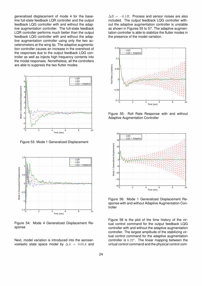
generalized displacement of mode 4 for the base-line full-state feedback LQR controller and the outputfeedback LQG controller with and without the adap-tive augmentation controller. The full-state feedbackLQR controller performs much better than the outputfeedback LQG controller with and without the adap-tive augmentation controller using only the two ac-celerometers at the wing tip. The adaptive augmenta-tion controller causes an increase in the overshoot ofthe responses due to the output feedback LQG con-troller as well as injects high frequency contents intothe modal responses. Nonetheless, all the controllersare able to suppress the two flutter modes.
0 2 4 6 8 10−3
−2
−1
0
1
2
3
4
5
6
7
Time (sec)
Mode 1
Genera
lized D
ispla
cem
ent
LQR
LQG
LQG + Adaptive
Figure 53: Mode 1 Generalized Displacement
0 2 4 6 8 10−1.5
−1
−0.5
0
0.5
1
1.5
Time (sec)
Mode 4
Genera
lized D
ispla
cem
ent
LQR
LQG
LQG + Adaptive
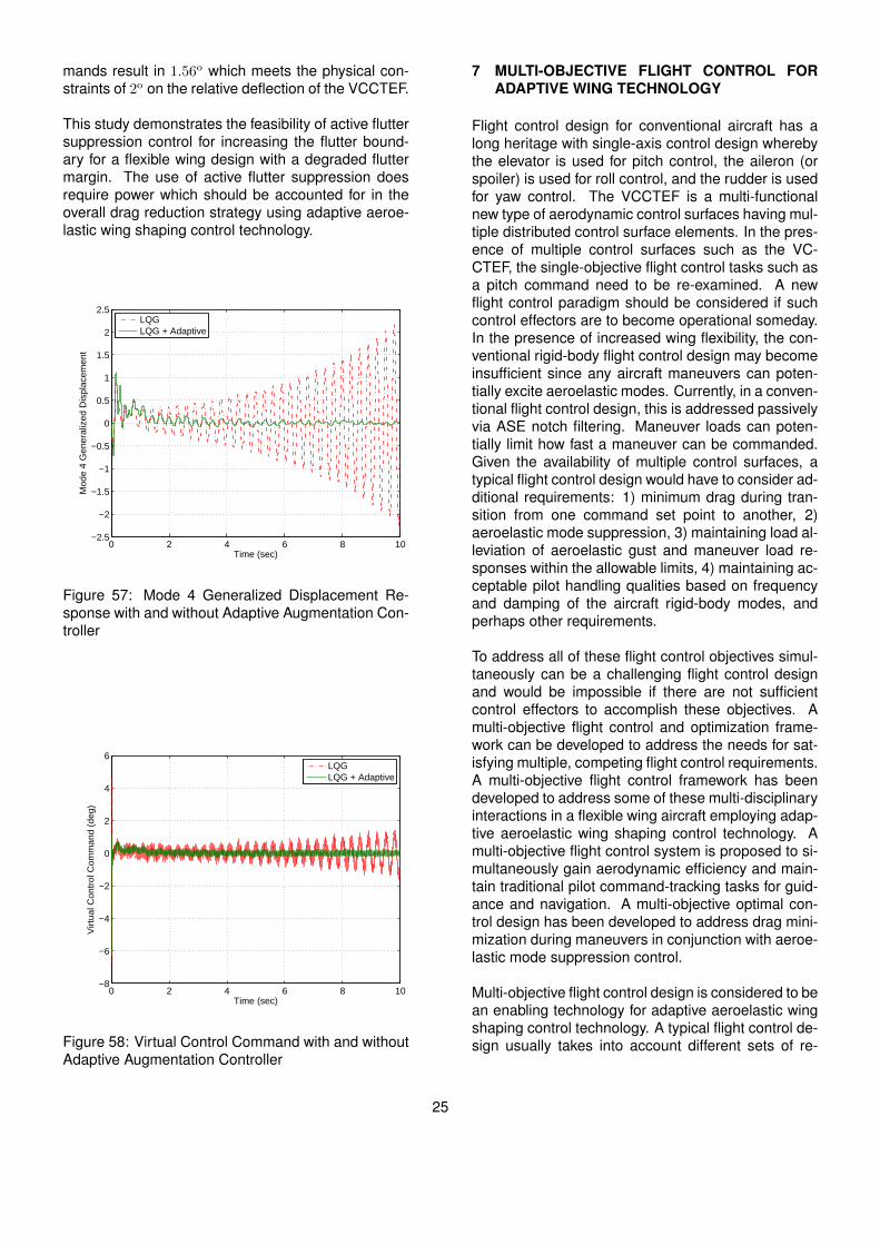
Figure 54: Mode 4 Generalized Displacement Re-sponse
Next, model variation is introduced into the aeroser-voelastic state space model by ∆A = 0.05A and
∆B = −0.1B. Process and sensor noises are alsoincluded. The output feedback LQG controller with-out the adaptive augmentation controller is unstableas shown in Figures 55 to 57. The adaptive augmen-tation controller is able to stabilize the flutter modes inthe presence of the model variation.
0 2 4 6 8 10−0.1
−0.05
0
0.05
0.1
0.15
Time (sec)
Roll R
ate
p (
rad/s
ec)
LQG
LQG + Adaptive
Figure 55: Roll Rate Response with and withoutAdaptive Augmentation Controller
0 2 4 6 8 10−20
−15
−10
−5
0
5
10
15
20
Time (sec)
Mode 1
Genera
lized D
ispla
cem
ent
LQG
LQG + Adaptive
Figure 56: Mode 1 Generalized Displacement Re-sponse with and without Adaptive Augmentation Con-troller
Figure 58 is the plot of the time history of the vir-tual control command for the output feedback LQGcontroller with and without the adaptive augmentationcontroller. The largest amplitude of the stabilizing vir-tual control command for the adaptive augmentationcontroller is 6.22o. The linear mapping between thevirtual control command and the physical control com-
24
mands result in 1.56o which meets the physical con-straints of 2o on the relative deflection of the VCCTEF.
This study demonstrates the feasibility of active fluttersuppression control for increasing the flutter bound-ary for a flexible wing design with a degraded fluttermargin. The use of active flutter suppression doesrequire power which should be accounted for in theoverall drag reduction strategy using adaptive aeroe-lastic wing shaping control technology.
0 2 4 6 8 10−2.5
−2
−1.5
−1
−0.5
0
0.5
1
1.5
2
2.5
Time (sec)
Mode 4
Genera
lized D
ispla
cem
ent
LQG
LQG + Adaptive
Figure 57: Mode 4 Generalized Displacement Re-sponse with and without Adaptive Augmentation Con-troller
0 2 4 6 8 10−8
−6
−4
−2
0
2
4
6
Time (sec)
Virtu
al C
ontr
ol C
om
mand (
deg)
LQG
LQG + Adaptive
Figure 58: Virtual Control Command with and withoutAdaptive Augmentation Controller
7 MULTI-OBJECTIVE FLIGHT CONTROL FORADAPTIVE WING TECHNOLOGY
Flight control design for conventional aircraft has along heritage with single-axis control design wherebythe elevator is used for pitch control, the aileron (orspoiler) is used for roll control, and the rudder is usedfor yaw control. The VCCTEF is a multi-functionalnew type of aerodynamic control surfaces having mul-tiple distributed control surface elements. In the pres-ence of multiple control surfaces such as the VC-CTEF, the single-objective flight control tasks such asa pitch command need to be re-examined. A newflight control paradigm should be considered if suchcontrol effectors are to become operational someday.In the presence of increased wing flexibility, the con-ventional rigid-body flight control design may becomeinsufficient since any aircraft maneuvers can poten-tially excite aeroelastic modes. Currently, in a conven-tional flight control design, this is addressed passivelyvia ASE notch filtering. Maneuver loads can poten-tially limit how fast a maneuver can be commanded.Given the availability of multiple control surfaces, atypical flight control design would have to consider ad-ditional requirements: 1) minimum drag during tran-sition from one command set point to another, 2)aeroelastic mode suppression, 3) maintaining load al-leviation of aeroelastic gust and maneuver load re-sponses within the allowable limits, 4) maintaining ac-ceptable pilot handling qualities based on frequencyand damping of the aircraft rigid-body modes, andperhaps other requirements.
To address all of these flight control objectives simul-taneously can be a challenging flight control designand would be impossible if there are not sufficientcontrol effectors to accomplish these objectives. Amulti-objective flight control and optimization frame-work can be developed to address the needs for sat-isfying multiple, competing flight control requirements.A multi-objective flight control framework has beendeveloped to address some of these multi-disciplinaryinteractions in a flexible wing aircraft employing adap-tive aeroelastic wing shaping control technology. Amulti-objective flight control system is proposed to si-multaneously gain aerodynamic efficiency and main-tain traditional pilot command-tracking tasks for guid-ance and navigation. A multi-objective optimal con-trol design has been developed to address drag mini-mization during maneuvers in conjunction with aeroe-lastic mode suppression control.
Multi-objective flight control design is considered to bean enabling technology for adaptive aeroelastic wingshaping control technology. A typical flight control de-sign usually takes into account different sets of re-
25

quirements for performance and stability that must beconsidered during a design process. Performance inthe context of flight control usually implies the abilityfor a flight control system to follow a pilot command.However, a new notion of aerodynamic performanceis introduced into the flight control framework. Thegoal of the new vehicle is to achieve low drag throughadaptive aeroelastic wing shaping control actuation.Thus, drag penalty due to the VCCTEF should beconsidered in a flight control design. Hence, a newconcept of drag-cognizant multi-objective flight con-trol is proposed to not only achieve a pilot command-following objective but also a drag reduction objective[2, 30] during maneuvers such as a pitch command orroll command.
Stability is of paramount importance for any flight ve-hicle. Structural flexibility of airframes including wingscan cause significant aeroelastic interactions that candegrade vehicle stability margins, potentially leadingto loss of control. There exists a trade-off betweenthe desire of having light-weight, flexible structuresfor weight savings and the need for maintaining suf-ficient robust stability margins from aeroelastic stabil-ity perspectives. For flexible wing aircraft, the flutterspeed boundary can occur below FAA flutter clear-ance. Thus, a flight control system must be able tostabilize aeroelastic modes. The VCCTEF systemmust be designed to achieve this objective. For ob-vious reasons, it is not acceptable to operate an un-stable transport vehicle that relies on feedback con-trol for closed-loop stability. Thus, in practice, passiveaeroelastic tailoring in the design process is used toincrease flutter margins. The role of a flight controlsystem would then be relegated to stability augmen-tation as opposed to a more demanding task of stabi-lization. This is considered more acceptable in thecertification framework as aircraft flight control sys-tems already have many stability augmentation de-sign features built in such as yaw and pitch dampersto provide desired damping characteristics to meet pi-lot handling quality requirements.
Gust and maneuver load alleviation control is alsoan important part of the overall flight control strategyfor flexible aircraft. As flexibility increases, the vehi-cle aeroelastic response to wind gust disturbances orduring a maneuver can result in structural integrityissues as well as handling and ride quality issues.Gust load alleviation control will reduce the aeroelas-tic response by reactive feedback control or predictivefeedforward control using early detection turbulencesensors. Similarly, maneuver loads can be kept towithin the operating load envelope by means of ma-neuver load alleviation control.
In terms of control actuation, the VCCTEF is designed
with dual purposes. The two inner chordwise flapsegments are driven by shaped memory alloy (SMA)actuators which are slow actuators suitable only forchanging the VCCTEF settings for cruise drag opti-mization either by scheduling or real-time drag op-timization. This is considered a guidance feature.For fast-acting flight control functions, the outermostchordwise flap segment is designed to be a fast act-ing control surface driven by electro-mechanical actu-ators (EMA). This flap segment is spanned the entirewing and is assumed to have sufficient bandwidth andcontrol power for roll control and aeroelastic modesuppression control.
The multi-objective flight control framework is en-visioned to comprise of the following objectives allacting in a synergistic manner: 1) traditional pilotcommand-following flight control, 2) drag minimiza-tion, 3) aeroelastic mode suppression, and 4) gustand maneuver load alleviation. Each of these objec-tives can be a major control system design in its ownrights. Thus, a multi-objective flight control systemcan be a complex flight control design that takes intoaccount multiple competing requirements to achieveoptimal flight control solutions that have the best com-promise for these requirements. Figure 59 illustratesan architecture of a multi-objective flight control sys-tem [30].
Figure 59: Multi-Objective Flight Control Architecture
In this study, we will consider the first three objec-tives. We will simplify some aspects of flight controldesign with a purpose of better illustrating the keysalient concepts as opposed to illuminating the detailcontrol theory. Traditional aircraft flight control is wellunderstood, so the focus will be on drag minimizationcontrol.
Consider a flight control design for a flight path anglecommand. Let xa =
´ t0
∆γdτ be an integral error stateof the flight path angle, where the error between the
26
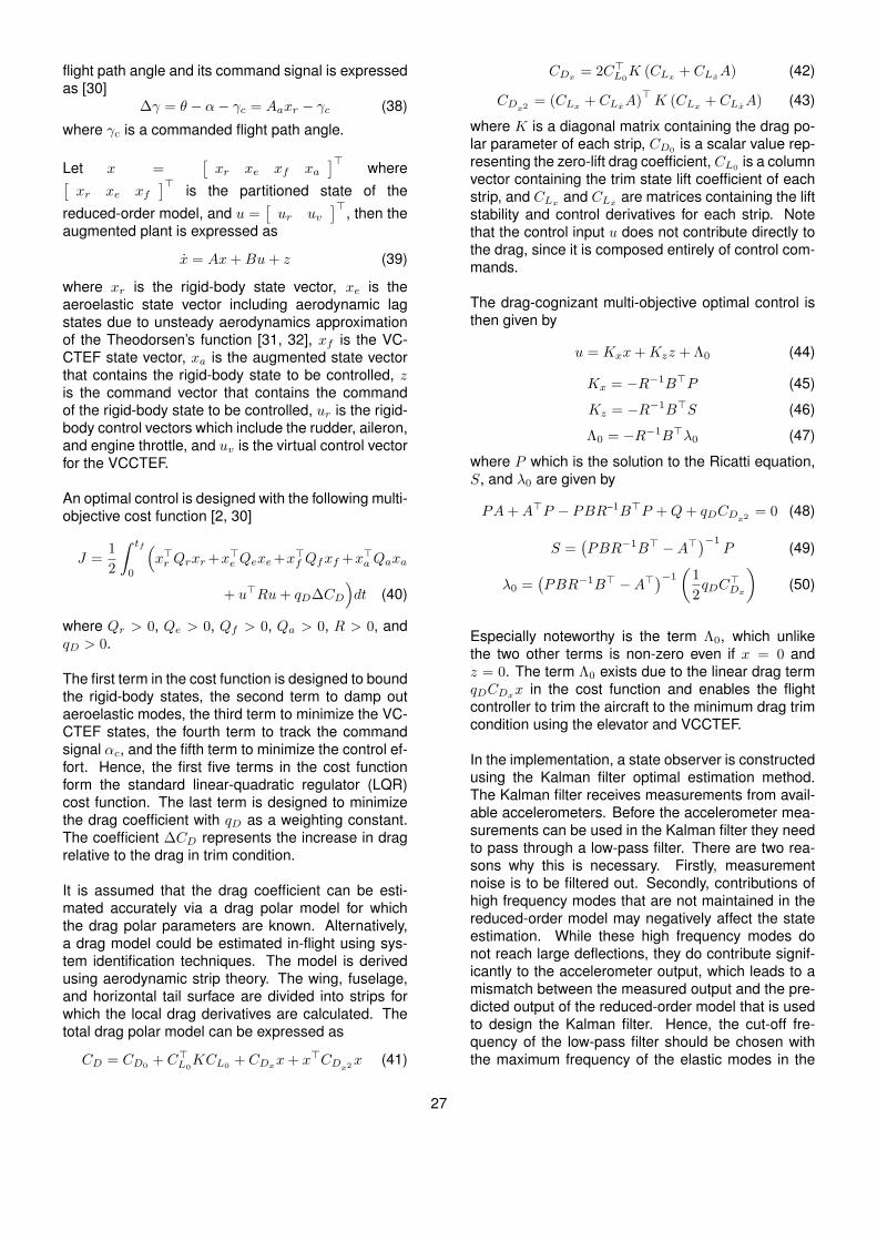
flight path angle and its command signal is expressedas [30]
∆γ = θ − α− γc = Aaxr − γc (38)
where γc is a commanded flight path angle.
Let x =[xr xe xf xa
]> where[xr xe xf
]> is the partitioned state of thereduced-order model, and u =
[ur uv
]>, then theaugmented plant is expressed as
x = Ax+Bu+ z (39)
where xr is the rigid-body state vector, xe is theaeroelastic state vector including aerodynamic lagstates due to unsteady aerodynamics approximationof the Theodorsen’s function [31, 32], xf is the VC-CTEF state vector, xa is the augmented state vectorthat contains the rigid-body state to be controlled, zis the command vector that contains the commandof the rigid-body state to be controlled, ur is the rigid-body control vectors which include the rudder, aileron,and engine throttle, and uv is the virtual control vectorfor the VCCTEF.
An optimal control is designed with the following multi-objective cost function [2, 30]
J =1
2
ˆ tf
0
(x>r Qrxr+x>e Qexe+x>f Qfxf +x>a Qaxa
+ u>Ru+ qD∆CD
)dt (40)
where Qr > 0, Qe > 0, Qf > 0, Qa > 0, R > 0, andqD > 0.
The first term in the cost function is designed to boundthe rigid-body states, the second term to damp outaeroelastic modes, the third term to minimize the VC-CTEF states, the fourth term to track the commandsignal αc, and the fifth term to minimize the control ef-fort. Hence, the first five terms in the cost functionform the standard linear-quadratic regulator (LQR)cost function. The last term is designed to minimizethe drag coefficient with qD as a weighting constant.The coefficient ∆CD represents the increase in dragrelative to the drag in trim condition.
It is assumed that the drag coefficient can be esti-mated accurately via a drag polar model for whichthe drag polar parameters are known. Alternatively,a drag model could be estimated in-flight using sys-tem identification techniques. The model is derivedusing aerodynamic strip theory. The wing, fuselage,and horizontal tail surface are divided into strips forwhich the local drag derivatives are calculated. Thetotal drag polar model can be expressed as
CD = CD0+ C>L0
KCL0+ CDxx+ x>CDx2x (41)
CDx = 2C>L0K (CLx + CLxA) (42)
CDx2 = (CLx + CLxA)>K (CLx + CLxA) (43)
where K is a diagonal matrix containing the drag po-lar parameter of each strip, CD0
is a scalar value rep-resenting the zero-lift drag coefficient, CL0 is a columnvector containing the trim state lift coefficient of eachstrip, and CLx and CLx are matrices containing the liftstability and control derivatives for each strip. Notethat the control input u does not contribute directly tothe drag, since it is composed entirely of control com-mands.
The drag-cognizant multi-objective optimal control isthen given by
u = Kxx+Kzz + Λ0 (44)
Kx = −R−1B>P (45)
Kz = −R−1B>S (46)
Λ0 = −R−1B>λ0 (47)
where P which is the solution to the Ricatti equation,S, and λ0 are given by
PA+A>P − PBR−1B>P +Q+ qDCDx2 = 0 (48)
S =(PBR−1B> −A>
)−1P (49)
λ0 =(PBR−1B> −A>
)−1(
1
2qDC
>Dx
)(50)
Especially noteworthy is the term Λ0, which unlikethe two other terms is non-zero even if x = 0 andz = 0. The term Λ0 exists due to the linear drag termqDCDxx in the cost function and enables the flightcontroller to trim the aircraft to the minimum drag trimcondition using the elevator and VCCTEF.
In the implementation, a state observer is constructedusing the Kalman filter optimal estimation method.The Kalman filter receives measurements from avail-able accelerometers. Before the accelerometer mea-surements can be used in the Kalman filter they needto pass through a low-pass filter. There are two rea-sons why this is necessary. Firstly, measurementnoise is to be filtered out. Secondly, contributions ofhigh frequency modes that are not maintained in thereduced-order model may negatively affect the stateestimation. While these high frequency modes donot reach large deflections, they do contribute signif-icantly to the accelerometer output, which leads to amismatch between the measured output and the pre-dicted output of the reduced-order model that is usedto design the Kalman filter. Hence, the cut-off fre-quency of the low-pass filter should be chosen withthe maximum frequency of the elastic modes in the
27

reduced-order model in mind. In order to minimizethe delay of the measurement signal by limiting thephase lag of the low-pass filter, a Bessel filter is used.
Multi-objective flight control can potentially enable amore functional flight control system to take advan-tages of multiple control surfaces available like theVCCTEF. The benefits of these flaps are driven bythe aerodynamic performance objective such as dragminimization. By including a drag minimization objec-tive in the control design, this directly addresses theultimate goal of the adaptive aeroelastic wing shap-ing control technology. While this study addressesthe inner-loop fast-acting control using the outermostflap segments of the VCCTEF, a more important as-pect of multi-objective flight control requirement totruly achieve adaptive aeroelastic wing shaping con-trol technology deals with the outer-loop guidance lawfor drag minimization during cruise. The two innerflap segments which are driven by lightweight slow-acting SMA actuators are designed to provide adap-tive wing shapes during cruise that minimizes drag.This outer-loop guidance can be based on a pre-programmed schedule of flap settings based on air-craft gross weight and flight conditions. Off-line opti-mization can be used to define these flap settings.
A more potentially game-changing approach toachieving a true adaptive wing is to have the abilityto determine the flap settings in real-time based onthe current aircraft information. This real-time dragminimization control strategy can increase the poten-tial benefits of adaptive aeroelastic wing shaping con-trol technology like the VCCTEF. However, drag mini-mization control can be challenging in many aspects.First of all, drag sensors must be available for real-time drag minimization control. A previous study con-ducted by NASA Armstrong Flight Research Centerhas developed a peak-seeking optimization for min-imizing the fuel flow as an indication of drag [33].Test flight on NASA F/A-18 research aircraft, tail num-ber 853, indicates fuel flow reduction is achieved withthis method. Since drag penalty is directly related tothe wing shape which changes continuously in-flightat off-design flight control, it may be possible to inferdrag from a wing shape sensor such as the fiber op-tic shape sensor (FOSS) being developed at NASAArmstrong Flight Research Center. Other types ofsensors for drag measurements could be developedin the future.
A real-time drag minimization control has been pro-posed in a recent study [30]. Consider a steady-statecruise flight during which the dynamics of aircraft,flexible wing, and flaps are no longer considered im-portant, so that the quasi-steady state drag coefficient
can be expressed as
CD = CD0 + (CL0 + CLxx+ CLuu)>K×
× (CL0 + CLxx+ CLuu) (51)
It should be noted that u is no longer a command vec-tor, but is a control vector such as elevator deflectionδe, thrust δT , and all the VCCTEF flaps. It is alsonoted that the drag polar parameter K is usually notknown precisely. For that matter, the lift derivativesare also not known precisely. Thus, one aspect ofreal-time drag minimization is parameter estimation.Let CD be the estimate of CD which is assumed to bemeasurable by suitable sensors. The drag coefficientcan be re-written as
CD = Θ>Φ (x, u) (52)
where Θ =[CD0
+ C>L0KCL0
CL0KCLx CL0
KCLu
CDx2 CDxu CDu2
]>, Φ (x, u) =
[1 x> u>
ele(xx>
)ele(xu>
)ele(uu>
) ]>, and ele (A) is
the element-wise column vector of A.
The drag parameter estimation can be computed inreal time using the following least-squares method
Θ = −Γ∇JΘ (Θ) = −ΓΦ (x, u)[Φ> (x, u) Θ− CD
](53)
where Γ is a tuning parameter.
As an aircraft passes through many different flightstates in-flight, information on drag, aircraft states,and control can be collected in flight computers forpost-processing. These past data can be used to es-timate drag in a least-squares sense. As more databecome available, and assuming that the drag mea-surements are sufficiently reliable and accurate, thenthe least squares estimation should yield a good ap-proximation of the drag model. Using this drag model,the control flaps can be computed for real-time dragminimization using a real-time drag minimization con-trol algorithm as
u = −1
2C−1Du2
(CDu + C>Dxux
)(54)
However the problem with this approach could lie inthe matrix inversion of CDu2 . This matrix could besmall. So when it is inverted, a large control solutionmay result. So, an adaptive algorithm could be usedinstead
u = −Γ(CDu + C>Dxux+ 2CDu2u
)(55)
28
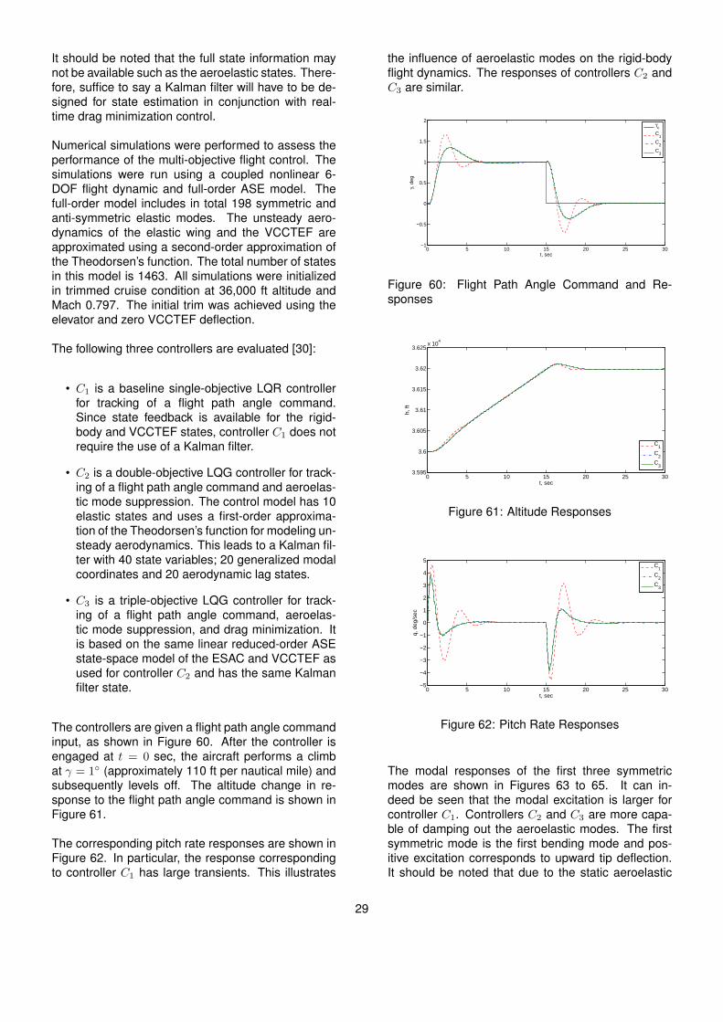
It should be noted that the full state information maynot be available such as the aeroelastic states. There-fore, suffice to say a Kalman filter will have to be de-signed for state estimation in conjunction with real-time drag minimization control.
Numerical simulations were performed to assess theperformance of the multi-objective flight control. Thesimulations were run using a coupled nonlinear 6-DOF flight dynamic and full-order ASE model. Thefull-order model includes in total 198 symmetric andanti-symmetric elastic modes. The unsteady aero-dynamics of the elastic wing and the VCCTEF areapproximated using a second-order approximation ofthe Theodorsen’s function. The total number of statesin this model is 1463. All simulations were initializedin trimmed cruise condition at 36,000 ft altitude andMach 0.797. The initial trim was achieved using theelevator and zero VCCTEF deflection.
The following three controllers are evaluated [30]:
• C1 is a baseline single-objective LQR controllerfor tracking of a flight path angle command.Since state feedback is available for the rigid-body and VCCTEF states, controller C1 does notrequire the use of a Kalman filter.
• C2 is a double-objective LQG controller for track-ing of a flight path angle command and aeroelas-tic mode suppression. The control model has 10elastic states and uses a first-order approxima-tion of the Theodorsen’s function for modeling un-steady aerodynamics. This leads to a Kalman fil-ter with 40 state variables; 20 generalized modalcoordinates and 20 aerodynamic lag states.
• C3 is a triple-objective LQG controller for track-ing of a flight path angle command, aeroelas-tic mode suppression, and drag minimization. Itis based on the same linear reduced-order ASEstate-space model of the ESAC and VCCTEF asused for controller C2 and has the same Kalmanfilter state.
The controllers are given a flight path angle commandinput, as shown in Figure 60. After the controller isengaged at t = 0 sec, the aircraft performs a climbat γ = 1◦ (approximately 110 ft per nautical mile) andsubsequently levels off. The altitude change in re-sponse to the flight path angle command is shown inFigure 61.
The corresponding pitch rate responses are shown inFigure 62. In particular, the response correspondingto controller C1 has large transients. This illustrates
the influence of aeroelastic modes on the rigid-bodyflight dynamics. The responses of controllers C2 andC3 are similar.
0 5 10 15 20 25 30−1
−0.5
0
0.5
1
1.5
2
γ,
de
g
t, sec
γc
C1
C2
C3
Figure 60: Flight Path Angle Command and Re-sponses
0 5 10 15 20 25 303.595
3.6
3.605
3.61
3.615
3.62
3.625x 10
4
h,
ft
t, sec
C1
C2
C3
Figure 61: Altitude Responses
0 5 10 15 20 25 30−5
−4
−3
−2
−1
0
1
2
3
4
5
q,
de
g/s
ec
t, sec
C
1
C2
C3
Figure 62: Pitch Rate Responses
The modal responses of the first three symmetricmodes are shown in Figures 63 to 65. It can in-deed be seen that the modal excitation is larger forcontroller C1. Controllers C2 and C3 are more capa-ble of damping out the aeroelastic modes. The firstsymmetric mode is the first bending mode and pos-itive excitation corresponds to upward tip deflection.It should be noted that due to the static aeroelastic
29

deformation of the wing in trim condition, the totalvertical tip deflection is upward throughout the sim-ulation for all controllers. The responses correspond-ing to controllers C2 and C3 are similar for the firsttwo modes. The third symmetric mode is the first tor-sion mode. The response corresponding to controllerC3 shows a negative response, which correspondsto nose-down twist of the wing in steady-state climband level flight. In essence, controller C3 re-trims theaircraft to minimize drag since it is a drag-cognizantmulti-objective flight controller.
0 5 10 15 20 25 30−8
−6
−4
−2
0
2
4
6
8
Mo
da
l E
xcita
tio
n
t, sec
C1
C2
C3
Figure 63: First Symmetric Modal Responses
0 5 10 15 20 25 30−0.25
−0.2
−0.15
−0.1
−0.05
0
0.05
0.1
0.15
0.2
0.25
Mo
da
l E
xcita
tio
n
t, sec
C1
C2
C3
Figure 64: Second Symmetric Modal Responses
0 5 10 15 20 25 30−0.2
−0.15
−0.1
−0.05
0
0.05
0.1
0.15
Modal E
xcitation
t, sec
C1
C2
C3
Figure 65: Third Symmetric Modal Responses
Figure 66 shows the incremental drag coefficient rel-
ative to the drag coefficient in the trim state. Con-troller C1 results in a larger incremental drag coeffi-cient in transient than for the two other controllers.The incremental drag coefficients in trim are similarfor controllers C1 and C2. It can be observed that thedrag coefficient corresponding to the drag-cognizantmulti-objective flight controller C3 is lower than thethose corresponding controllers C1 and C2 withoutdrag minimization.
0 5 10 15 20 25 30−0.02
−0.01
0
0.01
0.02
0.03
0.04
0.05
∆ C
D
t, sec
C
1
C2
C3
Figure 66: Drag Coefficient Responses
The lift-to-drag ratio curves can be seen in Figure 67.The values in the figure are normalized to the ini-tial trim lift-to-drag ratio obtained by trimming the air-craft using the elevator without the VCCTEF deflec-tion. During steady-state climb and level flight, con-troller C3 achieves an increase in lift-to-drag ratio ofapproximately 4% relative to controllers C1 and C2.
0 5 10 15
0.4
0.6
0.8
1
1.2
1.4
1.6
1.8
CL/C
D
t, sec
C
1
C2
C3
Figure 67: Lift-to-Drag Ratio Responses
This study demonstrates the potential benefits ofmulti-objective flight control as an enabling technol-ogy for adaptive aeroelastic wing shaping control.The inclusion of drag minimization in aircraft flightcontrol systems can further extend the capability ofadaptive aeroelastic wing shaping control technologyto achieve increased fuel efficiency of future transportaircraft.
30
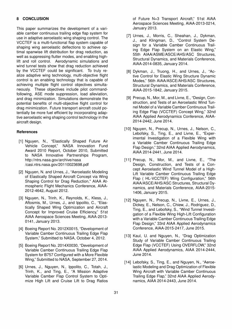
8 CONCLUSION
This paper summarizes the development of a vari-able camber continuous trailing edge flap system foruse in adaptive aeroelastic wing shaping control. TheVCCTEF is a multi-functional flap system capable ofshaping wing aeroelastic deflections to achieve op-timal spanwise lift distribution for drag reduction, aswell as suppressing flutter modes, and enabling high-lift and roll control. Aerodynamic simulations andwind tunnel tests show that drag reduction achievedby the VCCTEF could be significant. To truly re-alize adaptive wing technology, multi-objective flightcontrol is an enabling technology that is capable ofachieving multiple flight control objectives simulta-neously. These objectives include pilot command-following, ASE mode suppression, load alleviation,and drag minimization. Simulations demonstrate thepotential benefits of multi-objective flight control fordrag minimization. Future transport aircraft could po-tentially be more fuel efficient by incorporating adap-tive aeroelastic wing shaping control technology in theaircraft design.
References
[1] Nguyen, N., “Elastically Shaped Future AirVehicle Concept,” NASA Innovation FundAward 2010 Report, October 2010, Submittedto NASA Innovative Partnerships Program,http://ntrs.nasa.gov/archive/nasa/casi.ntrs.nasa.gov/20110023698.pdf
[2] Nguyen, N. and Urnes, J., “Aeroelastic Modelingof Elastically Shaped Aircraft Concept via WingShaping Control for Drag Reduction," AIAA At-mospheric Flight Mechanics Conference, AIAA-2012-4642, August 2012.
[3] Nguyen, N., Trinh, K., Reynolds, K., Kless, J.,Aftosmis, M., Urnes, J., and Ippolito, C., “Elas-tically Shaped Wing Optimization and AircraftConcept for Improved Cruise Efficiency,” 51stAIAA Aerospace Sciences Meeting, AIAA-2013-0141, January 2013.
[4] Boeing Report No. 2012X0015, “Development ofVariable Camber Continuous Trailing Edge FlapSystem,” Submitted to NASA, October 4, 2012.
[5] Boeing Report No. 2014X0030, “Development ofVariable Camber Continuous Trailing Edge FlapSystem for B757 Configured with a More FlexibleWing,” Submitted to NASA, September 27, 2014.
[6] Urnes, J., Nguyen, N., Ippolito, C., Totah, J.,Trinh, K., and Ting, E., “A Mission AdaptiveVariable Camber Flap Control System to Opti-mize High Lift and Cruise Lift to Drag Ratios
of Future N+3 Transport Aircraft,” 51st AIAAAerospace Sciences Meeting, AIAA-2013-0214,January 2013.
[7] Urnes, J., Morris, C., Sheahan, J., Dykman,J., and Klingman, D., “Control System De-sign for a Variable Camber Continuous Trail-ing Edge Flap System on an Elastic Wing,”55th AIAA/ASME/ASCE/AHS/ASC Structures,Structural Dynamics, and Materials Conference,AIAA-2014-0835, January 2014.
[8] Dykman, J., Truong, H., and Urnes, J., “Ac-tive Control for Elastic Wing Structure DynamicModes,” 56th AIAA/ASCE/AHS/ASC Structures,Structural Dynamics, and Materials Conference,AIAA-2015-1842, January 2015.
[9] Precup, N., Mor, M., and Livne, E., “Design, Con-struction, and Tests of an Aeroelastic Wind Tun-nel Model of a Variable Camber Continuous Trail-ing Edge Flap (VCCTEF) Concept Wing,” 32ndAIAA Applied Aerodynamics Conference, AIAA-2014-2442, June 2014.
[10] Nguyen, N., Precup, N., Urnes, J., Nelson, C.,Lebofsky, S., Ting, E., and Livne, E., “Exper-imental Investigation of a Flexible Wing witha Variable Camber Continuous Trailing EdgeFlap Design,” 32nd AIAA Applied Aerodynamics,AIAA 2014-2441, June 2014.
[11] Precup, N., Mor, M., and Livne, E., “TheDesign, Construction, and Tests of a Con-cept Aeroelastic Wind Tunnel Model of a High-Lift Variable Camber Continuous Trailing EdgeFlap ( HL-VCCTEF) Wing Configuration,” 56thAIAA/ASCE/AHS/ASC Structures, Structural Dy-namics, and Materials Conference, AIAA-2015-1406, January 2015.
[12] Nguyen, N., Precup, N., Livne, E., Urnes, J.,Dickey, E., Nelson, C., Chiew, J., Rodriguez, D.,Ting, E., and Lebofsky, S., “Wind Tunnel Investi-gation of a Flexible Wing High-Lift Configurationwith a Variable Camber Continuous Trailing EdgeFlap Design,” 33rd AIAA Applied AerodynamicsConference, AIAA-2015-2417, June 2015.
[13] Kaul, U. and Nguyen, N., “Drag OptimizationStudy of Variable Camber Continuous TrailingEdge Flap (VCCTEF) Using OVERFLOW,” 32ndAIAA Applied Aerodynamics, AIAA 2014-2444,June 2014.
[14] Lebofsky, S., Ting, E., and Nguyen, N., “Aeroe-lastic Modeling and Drag Optimization of FlexibleWing Aircraft with Variable Camber ContinuousTrailing Edge Flap,” 32nd AIAA Applied Aerody-namics, AIAA 2014-2443, June 2014.
31

[15] Lebofsky, S., Ting, E., and Nguyen, N., “Mul-tidisciplinary Drag Optimization of ReducedStiffness Flexible Wing Aircraft With VariableCamber Continuous Trailing Edge Flap,” 56thAIAA/ASME/ASCE/AHS/ASC Structures, Struc-tural Dynamics, and Materials Conference,AIAA-2015-1408, January 2015.
[16] Rodriguez, D., Aftosmis, M., Nemec, M., and An-derson, G., “Optimized Off-Design Performanceof Flexible Wings with Continuous Trailing-EdgeFlaps,” 56th AIAA/ASCE/AHS/ASC Structures,Structural Dynamics, and Materials Conference,AIAA-2015-1409, January 2015.
[17] Ting, E., Nguyen, N., and Trinh, K., “StaticAeroelastic and Longitudinal Trim Model ofFlexible Wing Aircraft Using Finite-ElementVortex-Lattice Coupled Solution,” 55thAIAA/ASME/ASCE/AHS/ASC Structures,Structural Dynamics, and Materials Conference,AIAA-2014-0837, January 2014.
[18] Stahara, S., “ Operational Manual for Two-Dimensional Transonic Code TSFOIL,” NASAContractor Report 3064, December 1978.
[19] Nguyen, N., Ting, E., Nguyen, D., Dao, T., andTrinh, K., “Coupled Vortex-Lattice Flight DynamicModel with Aeroelastic Finite-Element Model ofFlexible Wing Transport Aircraft with VariableCamber Continuous Trailing Edge Flap for DragReduction,” AIAA Atmospheric Flight Mechanics,AIAA-2013-4746, August 2013.
[20] Rodriguez, D., Aftosmis, M., Nemec, M.,and Smith, S., “Static Aeroelastic Analy-sis with an Inviscid Cartesian Method,” 55thAIAA/ASME/ASCE/AHS/ASC Structures, Struc-tural Dynamics, and Materials Conference,AIAA-2014-0836, January 2014.
[21] Liu, Y., Bai, J., and Livne, E., “Robust Opti-mization of Variable Camber Continuous Traili-ing Edge Flap System Action Using StochasticKriging,” 33nd AIAA Applied Aerodynamics Con-fererence, AIAA-2015-2421, June 2015.
[22] Chen, P., Zhou, Z., Ghoman, S., andFalkiewicz, N., “Low-Weight Low-Drag Truss-Braced Wing Design Using Variable Cam-ber Continuous Trailing Edge Flaps,” 56thAIAA/ASME/ASCE/AHS/ASC Structures, Struc-tural Dynamics, and Materials Conference,AIAA-2015-1176, January 2015.
[23] Lebofsky, S., Ting, E., Trinh, K., and Nguyen,N., “Optimization for Load Alleviation of Truss-Braced Wing Aircraft With Variable Camber Con-tinuous Trailing Edge Flap,” 33nd AIAA Applied
Aerodynamics Confererence, AIAA-2015-2723,June 2015.
[24] Nguyen, N., Swei, S., and Ting, E., “Adap-tive Linear Quadratic Gaussian Optimal ControlModification for Flutter Suppression of AdaptiveWing,” AIAA Infotech@Aerospace Conference,AIAA 2015-0118, January 2015.
[25] Nguyen, N., Ting, E., and Lebofsky, S.,“Aeroelastic Analysis of Wind Tunnel TestData of a Flexible Wing with a VariableCamber Continuous Trailing Edge Flap,” 56thAIAA/ASME/ASCE/AHS/ASC Structures, Struc-tural Dynamics, and Materials Conference,AIAA-2015-1405, January 2015.
[26] Yamauchi, G. K. and John, W., “Trends ofReynolds Number Effects on TWQ - DimensionalAirfoil Characteristics for Helicopter Rotor Analy-ses,” NASA TM 84363, April 1983.
[27] Stanford University AA241 Course Web-site, “Maximum Lift Prediction - Spe-cific Conceptual Design Methods,”http://adg.stanford.edu/aa241/highlift/clmaxest.html.
[28] White, F. M., Viscous Fluid Flow, McGraw-Hill,Second Edition, 1991.
[29] Nguyen, N., Ting, E., Nguyen, D., and Trinh,K., “Flutter Analysis of Mission-Adaptive Wingwith Variable Camber Continuous Trailing EdgeFlap,” 55th AIAA/ASME/ASCE/AHS/ASC Struc-tures, Structural Dynamics, and Materials Con-ference, AIAA-2014-0839, January 2014.
[30] Nguyen, N. and Tal, E., “A Multi-ObjectiveFlight Control Approach for Perfor-mance Adaptive Aeroelastic Wing,” 56thAIAA/ASME/ASCE/AHS/SC Structures, Struc-tural Dynamics, and Materials Conference,AIAA-2015-1843, January 2015.
[31] Nguyen, N., Ting, E., Nguyen, D., and Trinh,K., “Flight Dynamic Modeling and Stability Anal-ysis of Flexible Wing Generic Transport Air-craft,” 55th AIAA/ASME/ASCE/AHS/ASC Struc-tures, Structural Dynamics, and Materials Con-ference, AIAA-2014-1040, January 2014.
[32] Tal, E., Nguyen, N. and Ting, E., “Compari-son of Unsteady Aerodynamics Approximationsfor Time-Domain Representation of Frequency-Independent Aeroelastic State-Space Models,”56th AIAA/ASME/ASCE/AHS/ASC Structures,Structural Dynamics, and Materials Conference,AIAA-2015-1841, January 2015.
32
[33] Brown, N. and Schaefer, J., “Peak-Seeking Opti-mization of Trim for Reduced Fuel Consumption:Flight-Test Results,” AIAA Guidance, Navigation,and Control Conference, AIAA-2013-5171, Au-gust 2013.
33