a mission-adaptive variable camber flap control system to ... · a mission-adaptive variable camber...
TRANSCRIPT
A Mission-Adaptive Variable Camber Flap Control System toOptimize High Lift and Cruise Lift-to-Drag Ratios of Future
N+3 Transport Aircraft
James Urnes, Sr. ∗
Boeing Research & Technology, St. Louis, MO 63134Nhan Nguyen †, Corey Ippolito ‡, Joseph Totah§
NASA Ames Research Center, Moffett Field, CA 94035Khanh Trinh ¶, Eric Ting ‖
Stinger Ghaffarian Technologies, Inc. / NASA Ames Research Center, Moffett Field, CA 94035
Boeing and NASA are conducting a joint study program to design a wing flap system that will providemission-adaptive lift and drag performance for future transport aircraft having light-weight, flexible wings.This Variable Camber Continuous Trailing Edge Flap (VCCTEF) system offers a lighter-weight lift controlsystem having two performance objectives: (1) an efficient high lift capability for take-off and landing, and (2)reduction in cruise drag through control of the twist shape of the flexible wing. This control system duringcruise will command varying flap settings along the span of the wing in order to establish an optimum wingtwist for the current gross weight and cruise flight condition, and continue to change the wing twist as theaircraft changes gross weight and cruise conditions for each mission segment. Design weight of the flap controlsystem is being minimized through use of light-weight shape memory alloy (SMA) actuation augmented withelectric actuators. The VCCTEF program is developing better lift and drag performance of flexible wingtransports with the further benefits of lighter-weight actuation and less drag using the variable camber shapeof the flap.
I. Introduction
The aircraft industry has been responding to the need for energy-efficient aircraft by redesigning airframes to be
aerodynamically efficient, employing light-weight materials for aircraft structures and incorporating more energy-
efficient aircraft engines. Reducing airframe operational empty weight (OEW) using advanced composite materials
is one of the major considerations for improving energy efficiency. Modern light-weight materials can provide less
structural rigidity while maintaining sufficient load-carrying capacity. As structural flexibility increases, aeroelastic
interactions with aerodynamic forces and moments can alter aircraft aerodynamics significantly, thereby potentially
degrading aerodynamic efficiency.
Under the Fundamental Aeronautics Program at the NASA Aeronautics Research Mission Directorate, the Fixed
Wing (FW) project is conducting discipline-based and multidisciplinary foundational research to investigate advanced
concepts and technologies for future aircraft systems.
A NASA study entitled “Elastically Shape Future Air Vehicle Concept” was conducted in 20101 to examine new
concepts that can enable active control of wing aeroelasticity to achieve drag reduction. This study showed that highly
flexible wing aerodynamic surfaces can be elastically shaped in-flight by active control of wing twist and vertical
deflection in order to optimize the local angle of attack of wing sections to improve aerodynamic efficiency through
drag reduction during cruise and enhanced lift performance during take-off and landing.
∗Program Manager, Platform Systems/Subsystems Technology, [email protected], (314)234-3775†Associate Fellow AIAA, Intelligent Systems Division, [email protected], (650)604-4063‡Intelligent Systems Division, [email protected], (650)604-1605§Associate Fellow AIAA, Intelligent Systems Division, [email protected], (650)604-1864¶Intelligent Systems Division, [email protected], (650)604-5280‖Intelligent Systems Division, [email protected]
1 of 24
American Institute of Aeronautics and Astronautics
https://ntrs.nasa.gov/search.jsp?R=20140006948 2018-05-28T19:01:55+00:00Z
The study shows that active aeroelastic wing shaping control can have a potential drag reduction benefit. Conven-
tional flap and slat devices inherently generate drag as they increase lift. The study shows that conventional flap and
slat systems are not aerodynamically efficient for use in active aeroelastic wing shaping control for drag reduction. A
new flap concept, referred to as Variable Camber Continuous Trailing Edge Flap (VCCTEF) system, was developed to
address this need. Initial results indicate that the VCCTEF system may offer a potential pay-off for drag reduction that
will result in significant fuel savings. In order to realize the potential benefit of drag reduction by active aeroelastic
wing shaping control, configuration changes in high-lift devices have to be a part of the wing shaping control strategy.
A second study was awarded in 2011 under the NASA Subsonic Fixed Wing (SFW) project, entitled “Development
of Variable Camber Continuous Trailing Edge Flap System”.2 This study built upon the development of the VCCTEF
system for NASA Generic Transport Model (GTM) which is essentially based on the B757 airframe,3 employing
light-weight shaped memory alloy (SMA) technology for actuation and three separate chordwise segments shaped to
provide a variable camber to the flap. This cambered flap has potential for drag reduction as compared to a conventional
straight, plain flap. The flap is also made up of individual 2-foot spanwise sections which enable different flap setting
at each flap spanwise position. This results in the ability to control the wing twist shape as a function of span, resulting
in a change to the wing twist to establish the best lift-to-drag ratio (L/D) at any aircraft gross weight or mission
segment. Current wing twist on commercial transports is permanently set for one cruise configuration, usually for a
50% loading or mid-point on the gross weight schedule. The VCCTEF offers different wing twist settings for each
gross weight condition and also different settings for climb, cruise and descent, a major factor in obtaining best L/D
conditions.
The second feature of VCCTEF is a continuous trailing edge flap. The individual 2-foot spanwise flap sections
are connected with a flexible covering, so no breaks can occur in the flap platforms, thus reducing drag by eliminating
these breaks in the flap continuity which otherwise would generate vorticity that results in a drag increase and also
contributes to airframe noise. This continuous trailing edge flap design combined with the flap camber result in lower
drag increase during flap deflections. In addition, it also offers a potential noise reduction benefit.
The VCCTEF project has four objectives:
1. Use the VCCTEF to twist the flexible wing to obtain changes in lift-to-drag ratios that will reduce cruise drag
throughout the flight envelope.
2. Determine aeroelastic control approaches that will compensate for reduced flutter margins of flexible wings.
3. Use the full span cambered flap as the primary high lift device for take-off, climb-out, let-down and final ap-
proach.
4. Use the aft section of the cambered flap as a roll control effector and as an aeroservoelastic control device of
flexible wing structure dynamic modes.
II. Performance Benefit
Drag reduction by increasing lift-to-drag ratios through reshaping the wing twist has a significant advantage if
the wing has structural flexibility properties that will permit this change in shape. Current transport wing design
incorporates a twist profile that provides efficient lift-to-drag ratios, and the twist angle is set for an average flight
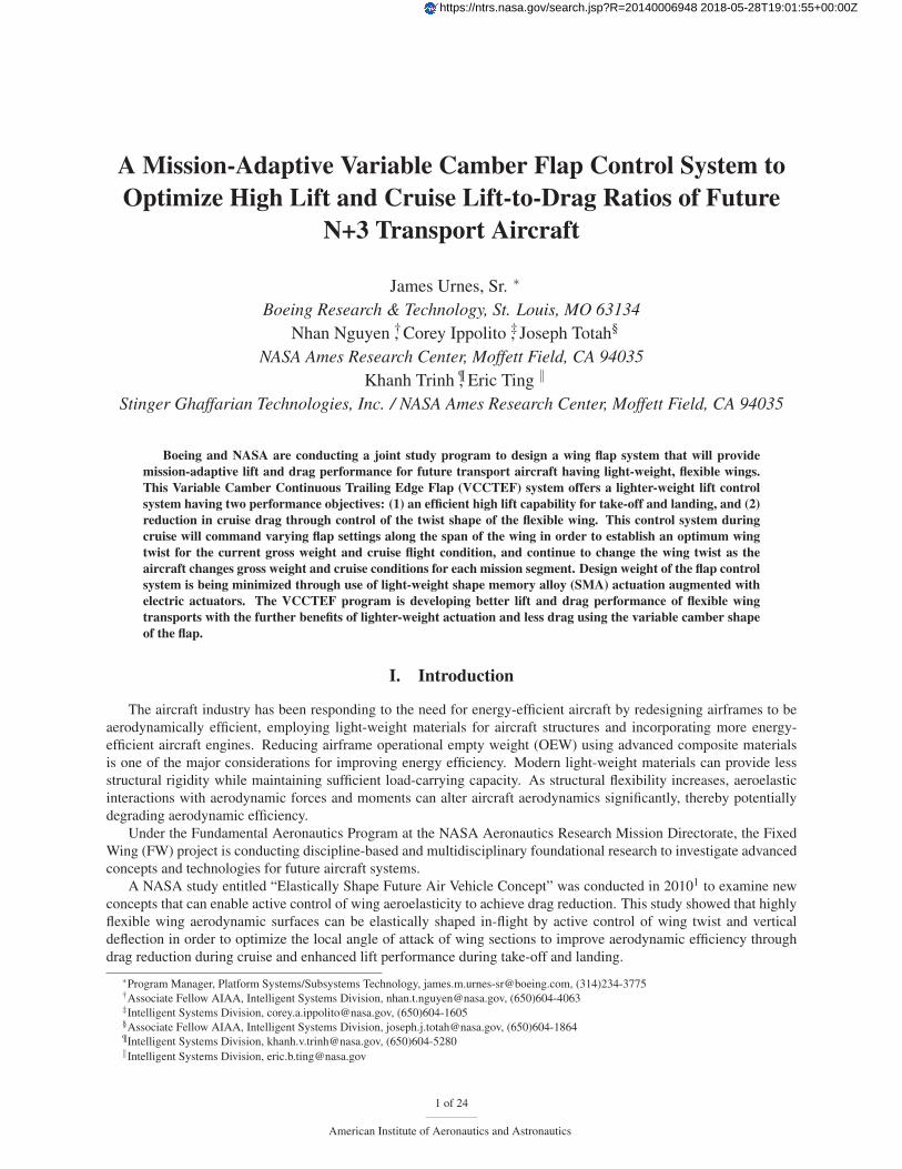
profile and at the mid-point gross weight. Figure 1 shows results of drag polars of a flexible wing transport for three
fuel loadings: 80% fuel load early in cruise, 50% fuel load at the mid-point cruise, and 20% fuel load toward the end
of cruise.
The 1-g trim points show the lowest drag at the 50% mid-point that is indicative of the wing twist design, with a
significant drag increase at the other fuel loading conditions due to wing shape changes for a flexible wing transport.
Using the VCCTEF, the drag polars can be changed to reduce drag, two examples are shown in Figure 1.1 The
important factor is to maintain the desired wing twist through the deflection of the VCCTEF, but not to lose the drag
benefit by having too much increase in drag due to the flap deflections. Hence, the use of the variable camber flap
instead of conventional flaps can offer a better drag signature.
2 of 24
American Institute of Aeronautics and Astronautics
0.25 0.3 0.35 0.4 0.45 0.5 0.55 0.6
0.01
0.015
0.02
0.025
0.03
CL
CD
80% Fuel w/ Aeroelastic Deflection50% Fuel @ Design Condition20% Fuel w/ Aeroelastic DeflectionVCCTE Flap Down 3.9 degVCCTE Flap Up −3.3 deg
1−g Trim Points
Nguyen, N., “Elastically Shaped Future Air Vehicle Concept,” NASA Innovation Fund Award 2010 Report, October 2010
Submitted to NASA Innovative Partnerships Program
Figure 1. Wing Shaping Control can Change the Lift-to-Drag Ratio to Minimize Trim Drag
III. Design of the VCCTEF System
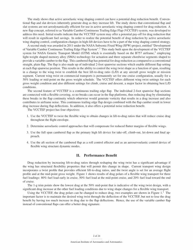
Figure 2 shows a wing and flap layout of the VCCTEF design for the GTM.
Figure 2. Wing Configured with the Variable Camber Continuous Trailing Edge Flap
The flap is divided into 14 sections attached to the outer wing and 3 sections attached to the inner wing. Each
24-inch section has three camber flap segments that can be individually commanded. These camber flaps are joined to
3 of 24
American Institute of Aeronautics and Astronautics
the next section by a flexible and supported material (shown in blue) installed with the same shape as the camber and
thus providing continuous flaps throughout the wing span with no drag producing gaps.
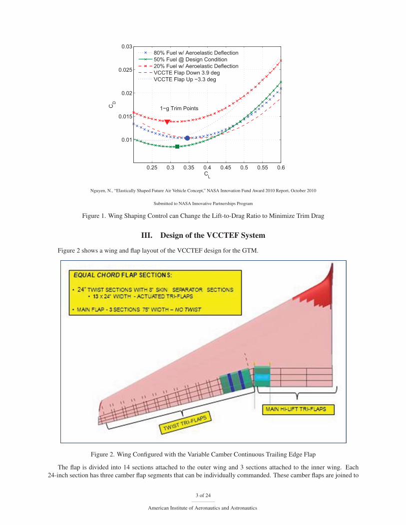
A major goal of the program is to develop a light-weight flap control system that has a significant weight advantage
as compared to current flap screw-jack actuators. Hydraulic, electric and Shape Memory Alloy (SMA) torque rod
actuation were evaluated with the result that the SMA actuation has the best weight advantage, as shown in Figure 3
hardware comparisons.
Moreover, the use of hinge line actuation eliminates the large and heavy external mounted actuators, and permits
all actuators to be interior to the wing and flap mold lines, thus contributing to the overall drag reduction goal.
Figure 3. Shape Memory Alloy Actuators Have a Low Weight Compared to Electric Motor Actuators
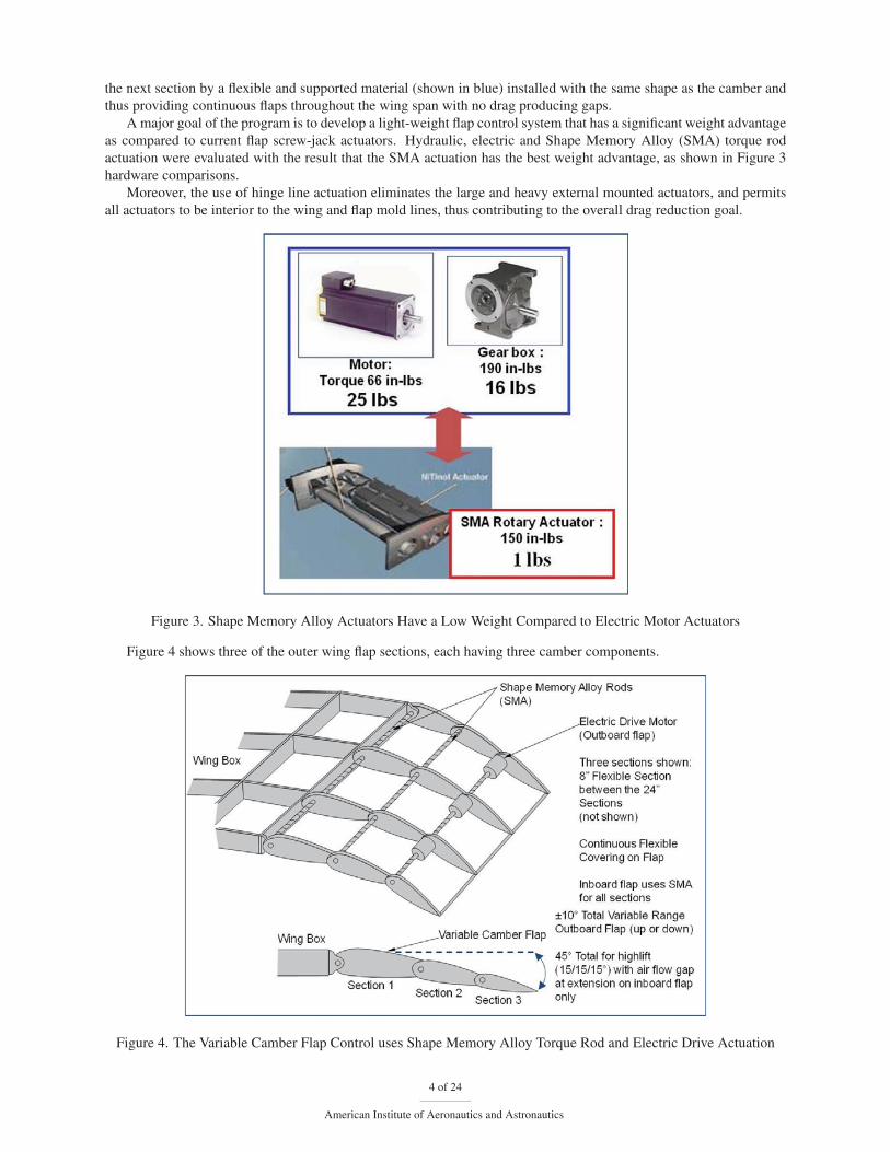
Figure 4 shows three of the outer wing flap sections, each having three camber components.
Figure 4. The Variable Camber Flap Control uses Shape Memory Alloy Torque Rod and Electric Drive Actuation
4 of 24
American Institute of Aeronautics and Astronautics
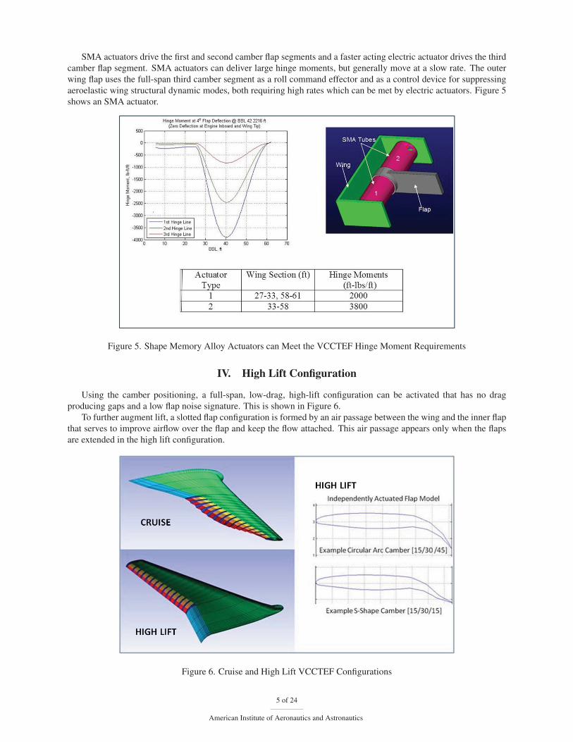
SMA actuators drive the first and second camber flap segments and a faster acting electric actuator drives the third
camber flap segment. SMA actuators can deliver large hinge moments, but generally move at a slow rate. The outer
wing flap uses the full-span third camber segment as a roll command effector and as a control device for suppressing
aeroelastic wing structural dynamic modes, both requiring high rates which can be met by electric actuators. Figure 5
shows an SMA actuator.
Figure 5. Shape Memory Alloy Actuators can Meet the VCCTEF Hinge Moment Requirements
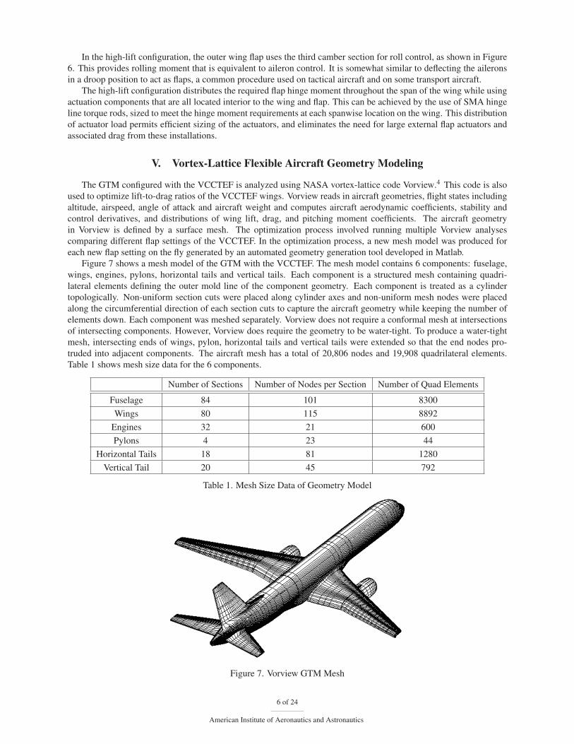
IV. High Lift Configuration
Using the camber positioning, a full-span, low-drag, high-lift configuration can be activated that has no drag
producing gaps and a low flap noise signature. This is shown in Figure 6.
To further augment lift, a slotted flap configuration is formed by an air passage between the wing and the inner flap
that serves to improve airflow over the flap and keep the flow attached. This air passage appears only when the flaps
are extended in the high lift configuration.
Figure 6. Cruise and High Lift VCCTEF Configurations
5 of 24
American Institute of Aeronautics and Astronautics
In the high-lift configuration, the outer wing flap uses the third camber section for roll control, as shown in Figure
6. This provides rolling moment that is equivalent to aileron control. It is somewhat similar to deflecting the ailerons
in a droop position to act as flaps, a common procedure used on tactical aircraft and on some transport aircraft.
The high-lift configuration distributes the required flap hinge moment throughout the span of the wing while using
actuation components that are all located interior to the wing and flap. This can be achieved by the use of SMA hinge
line torque rods, sized to meet the hinge moment requirements at each spanwise location on the wing. This distribution
of actuator load permits efficient sizing of the actuators, and eliminates the need for large external flap actuators and
associated drag from these installations.
V. Vortex-Lattice Flexible Aircraft Geometry Modeling
The GTM configured with the VCCTEF is analyzed using NASA vortex-lattice code Vorview.4 This code is also
used to optimize lift-to-drag ratios of the VCCTEF wings. Vorview reads in aircraft geometries, flight states including
altitude, airspeed, angle of attack and aircraft weight and computes aircraft aerodynamic coefficients, stability and
control derivatives, and distributions of wing lift, drag, and pitching moment coefficients. The aircraft geometry
in Vorview is defined by a surface mesh. The optimization process involved running multiple Vorview analyses
comparing different flap settings of the VCCTEF. In the optimization process, a new mesh model was produced for
each new flap setting on the fly generated by an automated geometry generation tool developed in Matlab.
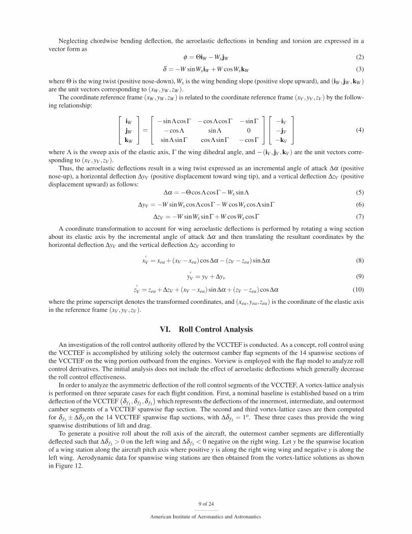
Figure 7 shows a mesh model of the GTM with the VCCTEF. The mesh model contains 6 components: fuselage,
wings, engines, pylons, horizontal tails and vertical tails. Each component is a structured mesh containing quadri-
lateral elements defining the outer mold line of the component geometry. Each component is treated as a cylinder
topologically. Non-uniform section cuts were placed along cylinder axes and non-uniform mesh nodes were placed
along the circumferential direction of each section cuts to capture the aircraft geometry while keeping the number of
elements down. Each component was meshed separately. Vorview does not require a conformal mesh at intersections
of intersecting components. However, Vorview does require the geometry to be water-tight. To produce a water-tight
mesh, intersecting ends of wings, pylon, horizontal tails and vertical tails were extended so that the end nodes pro-
truded into adjacent components. The aircraft mesh has a total of 20,806 nodes and 19,908 quadrilateral elements.
Table 1 shows mesh size data for the 6 components.
Number of Sections Number of Nodes per Section Number of Quad Elements
Fuselage 84 101 8300
Wings 80 115 8892
Engines 32 21 600
Pylons 4 23 44
Horizontal Tails 18 81 1280
Vertical Tail 20 45 792
Table 1. Mesh Size Data of Geometry Model
Figure 7. Vorview GTM Mesh
6 of 24
American Institute of Aeronautics and Astronautics

In meshing the VCCTEF wings, section cuts were placed at every flap/follower flexible material boundary. This
allows the mesh to correctly define the VCCTEF geometry in the wing spanwise direction. Likewise, mesh nodes along
each wing sections were placed to correctly define the flap geometry in the wing chord-wise direction. There were 3
quads along the chord-wise direction of each of the 3 chordwise flap sections. For each flap setting, the locations of
the 3 flap hinge rods were determined first. Then node locations of the quads defining each flap were calculated. Thus,
the sides of the flap quads follow the flap geometry boundaries. Figure 8 shows mesh of VCCTEF wings and mesh
sections for 2 different flap settings.
Vorview processes aircraft quad surface mesh along with user-defined control parameters to define slices and sub
polygons that are subsequently used in the aerodynamic calculations. Figure 8 shows Vorview slices and sub-polygons
of the GTM with VCCTEF, respectively.
Figure 8. Vorview GTM Sub-Polygons
The variable camber flap is modeled with three chordwise flap segments as shown in Figure 9.1
Nguyen, N., “Elastically Shaped Future Air Vehicle Concept,” NASA Innovation Fund Award 2010 Report, October 2010
Submitted to NASA Innovative Partnerships Program
Figure 9. Variable Camber Flap
The variable camber flap geometry is specified by three deflection values δ f1 , δ f2 , and δ f3 for the innermost,
intermediate, and outermost flap segments, respectively. The baseline camber shape is described by a circular arc,
with each flap segment deflected by the same amount relative to each other. With a circular arc camber, only one flap
deflection command is needed. For example, for a commanded flap deflection of 12o, the innermost flap segment is
deflected 4o, the intermediate flap segment is deflected 8o, and the outermost flap segment is deflected by 12o. Thus,
in general
δ fi =iδ fc
3(1)
7 of 24
American Institute of Aeronautics and Astronautics

where i = 1,2,3, and δ fc is the commanded flap deflection.
The camber angle of the circular arc camber flap is the difference between between δ f3 and δ f1 . Thus, the variable
camber angle χ = 2δ fc/3 is a function of the commanded flap deflection. A camber flap is more effective in producing
lift than a straight uncambered flap. As the camber increases, the pressure distribution at the aft of the airfoil increases
that results in a lift increase.
The variable camber flap produces about the same downwash as a simple plain flap deflected by the same angle
as shown in Figure 9–. However, the normal surface area of the variable camber flap exposed to the flow field is
significantly reduced. Thus, the drag reduction benefit of the variable camber flap is realized since the pressure drag
across the flap surface is reduced due to less exposed normal surface area.
In order to model a flexible wing aircraft, an automated geometry generation tool is developed in Matlab. This
geometry modeling uses structural deflection data computed by a finite-element model (FEM) to update the unde-
formed aircraft wing geometry to reflect static aeroelastic deflections. The deformed geometry, which reflects a series
of coordinate transformations on the outer mold line of the jig-shape aircraft wing, is processed into a geometry file
that can be used directly in vortex-lattice calculations.
With reference to Figure 10, the coordinate reference frame (xB,yB,zB) defines the Body Station (BS), the Body
Butt Line (BBL), and the Body Water Line (BWL) of the aircraft, respectively. The coordinate reference frame
(xV ,yV ,zV ) is the translated coordinate system attached to the nose of the aircraft such that xV = xB−13.25 ft, yV = yB,
and zV = zB −15.8333 ft. This reference frame is used for the vortex-lattice aerodynamic modeling and optimization.
The stability reference frame(x,y,z) is attached to the CG such that x = xV − xV , y = yV − yV , and z = zV − zV , where
(xV , yV , zV ) is the coordinate of the CG in the (xV ,yV ,zV ) reference frame.5
Figure 10. GTM Coordinate Systems
The wing reference frame is defined by the coordinate reference frame (xW ,yW ,zW ) as shown in Figure 11 . The
xW -axis is the wing elastic axis, the yW -axis points aft along the chord direction, and the zW -axis is the wing normal
direction.
Figure 11. Wing Bending Deflections and Twist
8 of 24
American Institute of Aeronautics and Astronautics
Neglecting chordwise bending deflection, the aeroelastic deflections in bending and torsion are expressed in a
vector form as
φ = ΘiW −WxjW (2)
δ =−W sinWxiW +W cosWxkW (3)
where Θ is the wing twist (positive nose-down), Wx is the wing bending slope (positive slope upward), and (iW , jW ,kW )are the unit vectors corresponding to (xW ,yW ,zW ).
The coordinate reference frame (xW ,yW ,zW ) is related to the coordinate reference frame (xV ,yV ,zV ) by the follow-
ing relationship: ⎡⎢⎣ iW
jW
kW
⎤⎥⎦=
⎡⎢⎣ −sinΛcosΓ −cosΛcosΓ −sinΓ
−cosΛ sinΛ 0
sinΛsinΓ cosΛsinΓ −cosΓ
⎤⎥⎦⎡⎢⎣ −iV
−jV
−kV
⎤⎥⎦ (4)
where Λ is the sweep axis of the elastic axis, Γ the wing dihedral angle, and −(iV , jV ,kV ) are the unit vectors corre-
sponding to (xV ,yV ,zV ).Thus, the aeroelastic deflections result in a wing twist expressed as an incremental angle of attack Δα (positive
nose-up), a horizontal deflection ΔyV (positive displacement toward wing tip), and a vertical deflection ΔzV (positive
displacement upward) as follows:
Δα =−ΘcosΛcosΓ−Wx sinΛ (5)
ΔyV =−W sinWx cosΛcosΓ−W cosWx cosΛsinΓ (6)
ΔzV =−W sinWx sinΓ+W cosWx cosΓ (7)
A coordinate transformation to account for wing aeroelastic deflections is performed by rotating a wing section
about its elastic axis by the incremental angle of attack Δα and then translating the resultant coordinates by the
horizontal deflection ΔyV and the vertical deflection ΔzV according to
x′V = xea +(xV − xea)cosΔα − (zV − zea)sinΔα (8)
y′V = yV +Δyv (9)
z′V = zea +ΔzV +(xV − xea)sinΔα +(zV − zea)cosΔα (10)
where the prime superscript denotes the transformed coordinates, and (xea,yea,zea) is the coordinate of the elastic axis
in the reference frame (xV ,yV ,zV ).
VI. Roll Control Analysis
An investigation of the roll control authority offered by the VCCTEF is conducted. As a concept, roll control using
the VCCTEF is accomplished by utilizing solely the outermost camber flap segments of the 14 spanwise sections of
the VCCTEF on the wing portion outboard from the engines. Vorview is employed with the flap model to analyze roll
control derivatives. The initial analysis does not include the effect of aeroelastic deflections which generally decrease
the roll control effectiveness.
In order to analyze the asymmetric deflection of the roll control segments of the VCCTEF, A vortex-lattice analysis
is performed on three separate cases for each flight condition. First, a nominal baseline is established based on a trim
deflection of the VCCTEF(δ f1 ,δ f2 ,δ f3
)which represents the deflections of the innermost, intermediate, and outermost
camber segments of a VCCTEF spanwise flap section. The second and third vortex-lattice cases are then computed
for δ f3 ±Δδ f3on the 14 VCCTEF spanwise flap sections, with Δδ f3 = 1o. These three cases thus provide the wing
spanwise distributions of lift and drag.
To generate a positive roll about the roll axis of the aircraft, the outermost camber segments are differentially
deflected such that Δδ f3 > 0 on the left wing and Δδ f3 < 0 negative on the right wing. Let y be the spanwise location
of a wing station along the aircraft pitch axis where positive y is along the right wing wing and negative y is along the
left wing. Aerodynamic data for spanwise wing stations are then obtained from the vortex-lattice solutions as shown
in Figure 12.
9 of 24
American Institute of Aeronautics and Astronautics
−80 −60 −40 −20 0 20 40 60 800
0.1
0.2
0.3
0.4
0.5
0.6
0.7
0.8
0.9
1
Spanwise Location y, ft
Loca
l Lift
Coe
ffici
ent c
l
Nominal VCCTEF SettingNegative −1o VCCTEF Roll Segments DeflectionPositive 1o VCCTEF Roll Segments Deflection
Figure 12. Local Lift Distribution with Differential Deflection of Outermost VCCTEF Segments for Roll Control
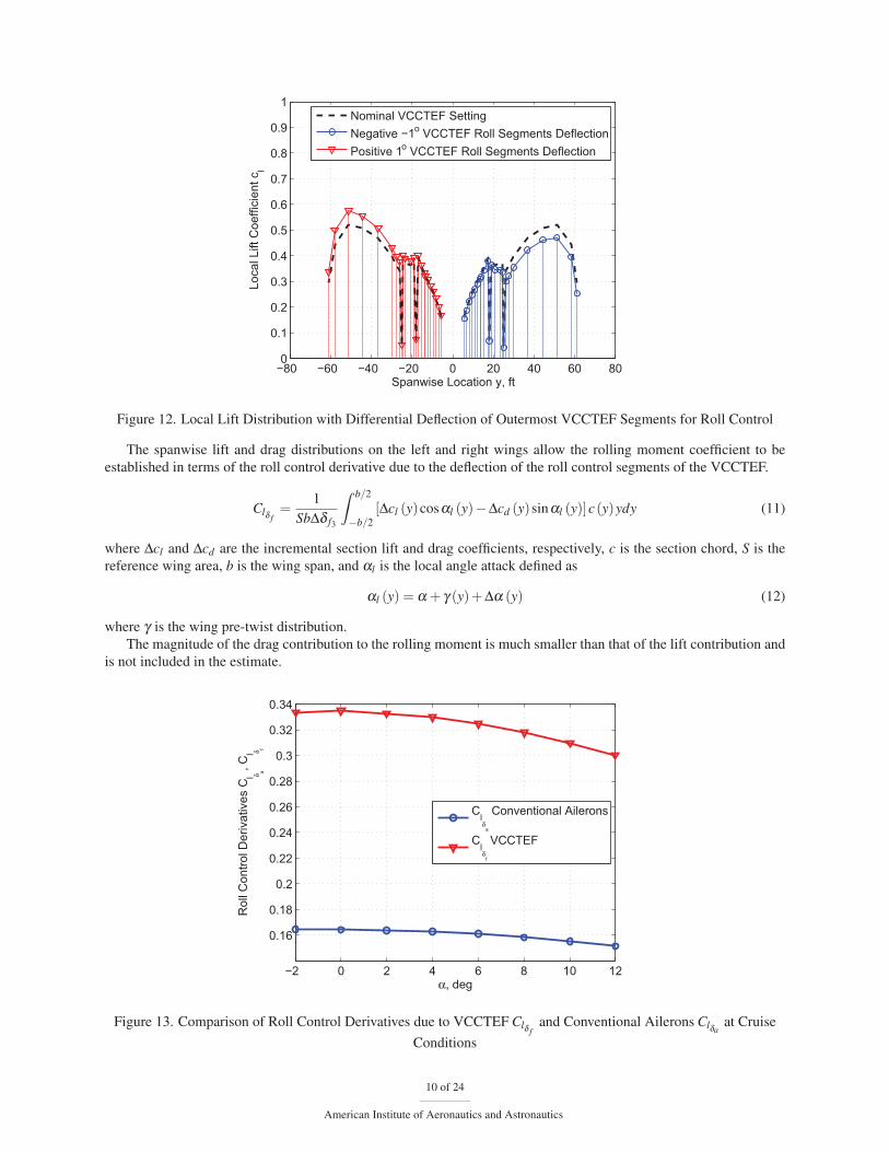
The spanwise lift and drag distributions on the left and right wings allow the rolling moment coefficient to be
established in terms of the roll control derivative due to the deflection of the roll control segments of the VCCTEF.
Clδ f=
1
SbΔδ f3
ˆ b/2
−b/2
[Δcl (y)cosαl (y)−Δcd (y)sinαl (y)]c(y)ydy (11)
where Δcl and Δcd are the incremental section lift and drag coefficients, respectively, c is the section chord, S is the
reference wing area, b is the wing span, and αl is the local angle attack defined as
αl (y) = α + γ (y)+Δα (y) (12)
where γ is the wing pre-twist distribution.
The magnitude of the drag contribution to the rolling moment is much smaller than that of the lift contribution and
is not included in the estimate.
−2 0 2 4 6 8 10 12
0.16
0.18
0.2
0.22
0.24
0.26
0.28
0.3
0.32
0.34
α, deg
Rol
l Con
trol D
eriv
ativ
es C
l δ a, Cl δ f
Clδ
a
Conventional Ailerons
Clδ
f
VCCTEF
Figure 13. Comparison of Roll Control Derivatives due to VCCTEF Clδ fand Conventional Ailerons Clδa
at Cruise
Conditions
10 of 24
American Institute of Aeronautics and Astronautics
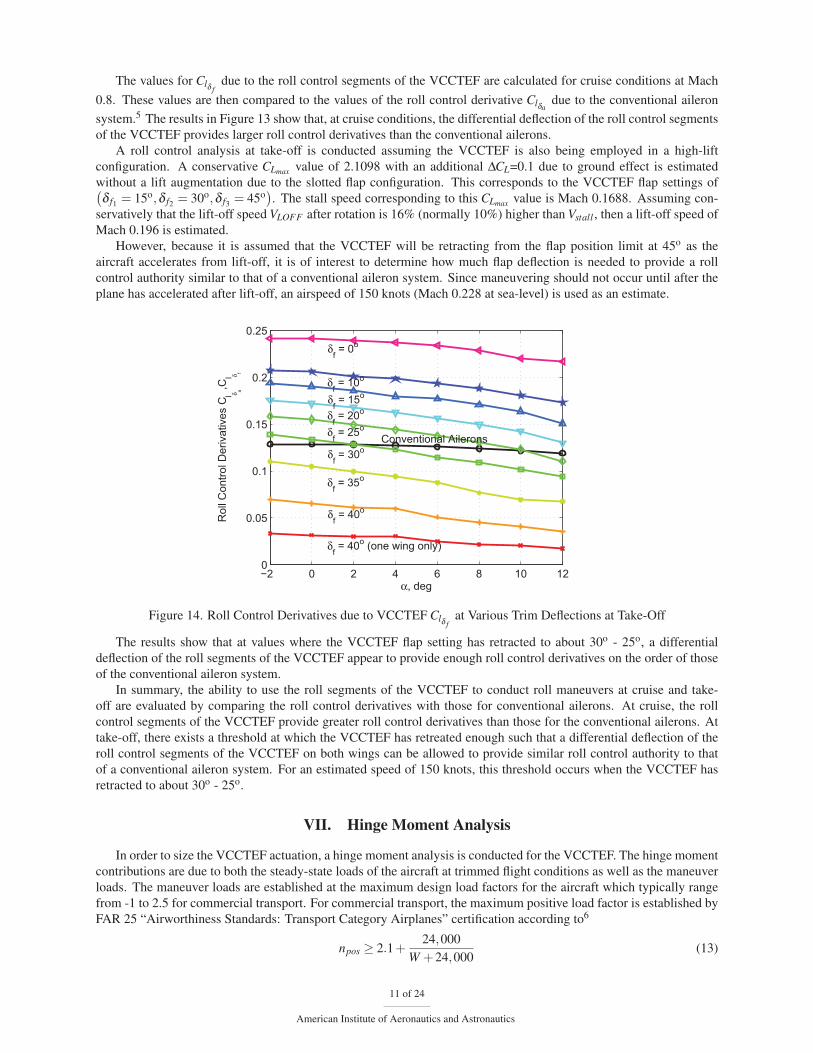
The values for Clδ fdue to the roll control segments of the VCCTEF are calculated for cruise conditions at Mach
0.8. These values are then compared to the values of the roll control derivative Clδadue to the conventional aileron
system.5 The results in Figure 13 show that, at cruise conditions, the differential deflection of the roll control segments
of the VCCTEF provides larger roll control derivatives than the conventional ailerons.
A roll control analysis at take-off is conducted assuming the VCCTEF is also being employed in a high-lift
configuration. A conservative CLmax value of 2.1098 with an additional ΔCL=0.1 due to ground effect is estimated
without a lift augmentation due to the slotted flap configuration. This corresponds to the VCCTEF flap settings of(δ f1 = 15o,δ f2 = 30o,δ f3 = 45o
). The stall speed corresponding to this CLmax value is Mach 0.1688. Assuming con-
servatively that the lift-off speed VLOFF after rotation is 16% (normally 10%) higher than Vstall , then a lift-off speed of
Mach 0.196 is estimated.
However, because it is assumed that the VCCTEF will be retracting from the flap position limit at 45o as the
aircraft accelerates from lift-off, it is of interest to determine how much flap deflection is needed to provide a roll
control authority similar to that of a conventional aileron system. Since maneuvering should not occur until after the
plane has accelerated after lift-off, an airspeed of 150 knots (Mach 0.228 at sea-level) is used as an estimate.
−2 0 2 4 6 8 10 120
0.05
0.1
0.15
0.2
0.25
α, deg
Rol
l Con
trol D
eriv
ativ
es C
l δ a,Cl δ f
δf = 40o (one wing only)
δf = 40o
δf = 35o
δf = 30o
δf = 10o
δf = 0o
δf = 25o
δf = 20o
δf = 15o
Conventional Ailerons
Figure 14. Roll Control Derivatives due to VCCTEF Clδ fat Various Trim Deflections at Take-Off
The results show that at values where the VCCTEF flap setting has retracted to about 30o - 25o, a differential
deflection of the roll segments of the VCCTEF appear to provide enough roll control derivatives on the order of those
of the conventional aileron system.
In summary, the ability to use the roll segments of the VCCTEF to conduct roll maneuvers at cruise and take-
off are evaluated by comparing the roll control derivatives with those for conventional ailerons. At cruise, the roll
control segments of the VCCTEF provide greater roll control derivatives than those for the conventional ailerons. At
take-off, there exists a threshold at which the VCCTEF has retreated enough such that a differential deflection of the
roll control segments of the VCCTEF on both wings can be allowed to provide similar roll control authority to that
of a conventional aileron system. For an estimated speed of 150 knots, this threshold occurs when the VCCTEF has
retracted to about 30o - 25o.
VII. Hinge Moment Analysis
In order to size the VCCTEF actuation, a hinge moment analysis is conducted for the VCCTEF. The hinge moment
contributions are due to both the steady-state loads of the aircraft at trimmed flight conditions as well as the maneuver
loads. The maneuver loads are established at the maximum design load factors for the aircraft which typically range
from -1 to 2.5 for commercial transport. For commercial transport, the maximum positive load factor is established by
FAR 25 “Airworthiness Standards: Transport Category Airplanes” certification according to6
npos ≥ 2.1+24,000
W +24,000(13)
11 of 24
American Institute of Aeronautics and Astronautics

where W is the aircraft weight.
Thus, for a 200,000-lb aircraft, the maximum positive load factor npos is established to be greater than +2.2143.
For the scope of this analysis, the maximum positive load factor is thus chosen to be +2.5. At lower Mach numbers,
the maximum load factor is established at the stall angle of attack αstall . At higher Mach numbers, the maximum load
factor is limited by structural design limit established by npos. In analyzing the worst-case hinge moments, coordinated
turn maneuvers are assumed to correspond to the maximum load factor.
To conduct a coordinated turn maneuver, a heading angle control is designed to track a coordinated turn command
that involves both yaw rate and bank angle command. The linearized heading angle equation obtained by linearization
of the kinematic equation is given by
ψ = r sec θ (14)
For small angles, ψ = r.
When turning, the heading angle as well as the bank angle are changing. A steady-state coordinated turn in the
horizontal plane is described by a motion at a constant heading angle rate or yaw rate while the airspeed and altitude
are not changing. Thus, the commands for a steady-state coordinated turn are given by
rc =g√
n2 −1
V(15)
φc = cos−1 1
n(16)
where n = L/W is the load factor.
The lateral-directional dynamics are described by⎡⎢⎢⎢⎣
βprφ
⎤⎥⎥⎥⎦=
⎡⎢⎢⎢⎣
Yβu
Ypu + α Yr
u −1 gu
Lβ Lp Lr 0
Nβ Np Nr 0
0 1 0 0
⎤⎥⎥⎥⎦⎡⎢⎢⎢⎣
βprφ
⎤⎥⎥⎥⎦+
⎡⎢⎢⎢⎣
Yδau
Yδru
Lδa Lδr
Nδa Nδr
0 0
⎤⎥⎥⎥⎦[
δa
δr
](17)
The steady state analysis is governed by
φ = p = 0 (18)
β =Yβ
uβ +
(Yr
u−1
)rc +
gu
φc +Yδa
uδa +
Yδr
uδr = 0 (19)
p = Lβ β +Lrrc +Lδaδa +Lδr δr = 0 (20)
r = Nβ β +Nrrc +Nδaδa +Nδr δr = 0 (21)
Solving for Δβ from (18) yields
β =− (Yr − u)rc +gφc +Yδa δa +Yδr δr
Yβ(22)
Substituting this into (20) and (21) gives the steady state roll and yaw equations
−Lβ gYβ
φc +
[Lr −
Lβ (Yr − u)Yβ
]rc +
(Lδa −
LβYδa
Yβ
)δa +
(Lδr −
LβYδr
Yβ
)δr = 0 (23)
−Nβ gYβ
φc +
[Nr −
Nβ (Yr − u)Yβ
]rc +
(Nδa −
NβYδa
Yβ
)δa +
(Nδr −
NβYδr
Yβ
)δr = 0 (24)
which can be solved for δa and δr given rc and φc as a function of the load factor n.
Since CYδa≈ 0, Cnδa
≈ 0, then δa and δr can be obtained from
−Lβ gφc +[LrYβ −Lβ (Yr − u)
]rc +LδaYβ δa +
(LδrYβ −LβYδr
)δr = 0 (25)
−Nβ gφc +[NrYβ −Nβ (Yr − u)
]rc +
(NδrYβ −NβYδr
)δr = 0 (26)
For the cruise condition with 80% fuel remaining at Mach 0.8 and 30,000 ft corresponding to α = 1.81o and
u = 795.6 ft/sec, the stability and control derivatives are given by CYβ = −1.3425, CYr = 1.0552, CYδr= 0.4249,
Clβ = −0.2444, Clr = 0.1743, Clδa= 0.3332, Clδr
= 0.0533, Cnβ = 0.3053, Cnr = −0.5307, Cnδr= −0.2402. The
aircraft properties are specified as S = 1951 ft2, m = 190,000/32.174 slug, Ixx = 1,770,000 slug-ft2, Izz = 7,270,000
slug-ft2.5 Then
12 of 24
American Institute of Aeronautics and Astronautics
Yβ =Cyβ qS
m =−124.8779 Lβ =Clβ
qSb
Ixx=−9.4684 Nβ =
Cnβ qSb
Izz= 2.8797
Yr =Cyr qSb
2mu = 7.7001 Lr =Clr qSb2
2Ixxu = 0.5297 Nr =Cnr qSb2
2Izzu =−0.3927
Yδa =Cyδa
qSm ≈ 0 Lδa =
ClδaqSb
Ixx= 12.9087 Nδa =
CnδaqSb
Izz≈ 0
Yδr =Cyδr
qSm = 39.5237 Lδr =
ClδrqSb
Ixx= 2.0649 Nδr =
CnδrqSb
Izz=−2.2656
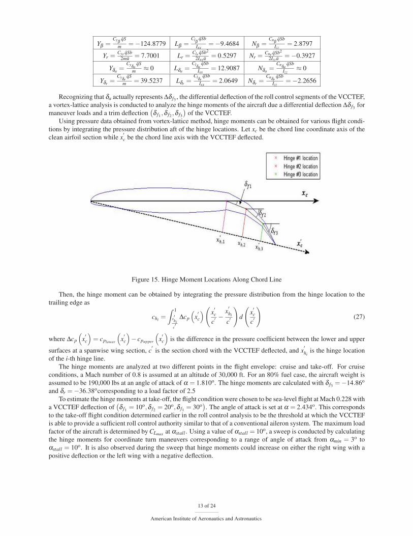
Recognizing that δa actually represents Δδ f3 , the differential deflection of the roll control segments of the VCCTEF,
a vortex-lattice analysis is conducted to analyze the hinge moments of the aircraft due a differential deflection Δδ f3 for
maneuver loads and a trim deflection(δ f1 ,δ f2 ,δ f3
)of the VCCTEF.
Using pressure data obtained from vortex-lattice method, hinge moments can be obtained for various flight condi-
tions by integrating the pressure distribution aft of the hinge locations. Let xc be the chord line coordinate axis of the
clean airfoil section while x′c be the chord line axis with the VCCTEF deflected.
Figure 15. Hinge Moment Locations Along Chord Line
Then, the hinge moment can be obtained by integrating the pressure distribution from the hinge location to the
trailing edge as
chi =
ˆ 1
x′hic′
Δcp
(x′c
)(x′c
c′ −x′hi
c′
)d
(x′c
c′
)(27)
where Δcp
(x′c
)= cplower
(x′c
)− cpupper
(x′c
)is the difference in the pressure coefficient between the lower and upper
surfaces at a spanwise wing section, c′
is the section chord with the VCCTEF deflected, and x′hi
is the hinge location
of the i-th hinge line.
The hinge moments are analyzed at two different points in the flight envelope: cruise and take-off. For cruise
conditions, a Mach number of 0.8 is assumed at an altitude of 30,000 ft. For an 80% fuel case, the aircraft weight is
assumed to be 190,000 lbs at an angle of attack of α = 1.810o. The hinge moments are calculated with δ f3 =−14.86o
and δr =−36.38ocorresponding to a load factor of 2.5
To estimate the hinge moments at take-off, the flight condition were chosen to be sea-level flight at Mach 0.228 with
a VCCTEF deflection of(δ f1 = 10o,δ f2 = 20o,δ f1 = 30o
). The angle of attack is set at α = 2.434o. This corresponds
to the take-off flight condition determined earlier in the roll control analysis to be the threshold at which the VCCTEF
is able to provide a sufficient roll control authority similar to that of a conventional aileron system. The maximum load
factor of the aircraft is determined by CLmax at αstall . Using a value of αstall = 10o, a sweep is conducted by calculating
the hinge moments for coordinate turn maneuvers corresponding to a range of angle of attack from αmin = 3o to
αstall = 10o. It is also observed during the sweep that hinge moments could increase on either the right wing with a
positive deflection or the left wing with a negative deflection.
13 of 24
American Institute of Aeronautics and Astronautics

0 0.01 0.02 0.03 0.04 0.05 0.06 0.07−4500
−4000
−3500
−3000
−2500
−2000
−1500
−1000
−500
0
BBL, ft
Hin
ge M
omen
t, lb
−ft/f
t
Hinge 1Hinge 2Hinge 3
Figure 16. Estimated Worst-Case Hinge Moments
The estimated worst-case hinge moments for the three camber flap segments are determined by combining the
largest moments for the cruise and take-off conditions. It is of interest to note that the worst-case hinge moments for
the wing portion inboard of the engines are dominated by the hinge moments during take-off with maneuver loads.
The worst-case hinge moments on the outboard wing portion are determined by the cruise condition with maneuver
loads.
VIII. Aeroelastic Modeling and Analysis
The aeroelastic model of the GTM with VCCTEF is based on one-dimensional structural dynamic theory that cap-
tures the aeroelastic deformation of a wing structure in a combined motion that involves flapwise bending, chordwise
bending, and torsion. The model includes the effect of aircraft propulsion due to wing flexibility which causes the
propulsive forces and moments to couple with the wing elastic motion. Engine mass is also accounted in the model.
A fuel management model is developed to describe the wing mass change due to fuel usage in the main tank and wing
tanks during cruise.
The model computes both static and dynamic responses of the wing structures. The static aeroelastic deflections
are used to estimate the effect of wing flexibility on induced drag and the potential drag reduction by the VCCTEF
system. A flutter analysis is conducted to estimate the flutter speed boundary.
The aeroelastic angle of attack includes the rigid-body angle of attack, wing wash-out pre-twist, induced angle
of attack due to local downwash, and wing twist and bending deflection. Neglecting the induced angle of attack, the
aeroelastic angle of attack at the aerodynamic center of a wing section is given by7
αac =α
cosΛ− γ −Θ+
eΘt
V∞ cosΛ−Wx tanΛ− Wt
V∞ cosΛ(28)
where γ is the wing wash-out pre-wist angle, e is the forward distance of the aerodynamic center from the elastic
center, V∞ is the airspeed, and the subscripts x and t denote the partial derivatives with respect to the wing position xand time t.
The aeroelastic angle of attack at the mid-chord location is given by
αmc =α
cosΛ− γ −Θ− emΘt
V∞ cosΛ−Wx tanΛ− Wt
V∞ cosΛ(29)
where em is the forward distance of the aeroelastic center from the mid-chord location.
Based on unsteady aerodynamics theory,8 the wing section lift coefficient is given by
cLac = cLαC (k)αac + cLδ δ (30)
14 of 24
American Institute of Aeronautics and Astronautics

where k = ωc2V∞
is the reduced frequency parameter, ω is the frequency of wing oscillations, c is the section chord, cLα
is the section lift curve slope, cLδ is the section lift derivative, and δ is the control surface deflection.
The function C (k) is the Theodorsen’s complex-valued function which is also expressed in terms of Bessel func-
tions as8
C (k) = F (k)+ iG(k) (31)
where F (k)> 0 and G(k)< 0.
Consider the case when the wing undergoes a simple harmonic motion
αac = αeiωt (32)
Then
αac = iωαeiωt = iωαac (33)
Thus the wing section lift coefficient due to unsteady aerodynamics is expressed as
cLac = cLα αacF (k)+ cLααacc2V∞
G(k)k
+ cLδ δ (34)
In addition, the apparent mass of the air contributes to the lift force acting at the mid-chord location as
cLmc =παmcc
2V∞(35)
The total section lift coefficient is
cL = cLac + cLmc (36)
The section pitching moment coefficient is evaluated as
cm = cmac +ec
cLac −em
ccLmc + cmδ δ (37)
where cmac is the section pitching moment coefficient at the aerodynamic center and cmδ is the section pitching moment
derivative at the aerodynamic center due to the control surface deflection δ .
The combined bending and torsion aeroelastic equations are given by
(GJΘx)x =
[ccmac + ecLα
(α
cosΛ− γ −Θ+
eΘt
V∞ cosΛ−Wx tanΛ− Wt
V∞ cosΛ
)F (k)
+ ecLα
(α
cosΛ−Θt +
eΘtt
V∞ cosΛ−Wxt tanΛ− Wtt
V∞ cosΛ
)c
2V∞
G(k)k
+(ccmδ + ecLδ
)δ
− emπc
2V∞
(α
cosΛ−Θt − emΘtt
V∞ cosΛ−Wxt tanΛ− Wtt
V∞ cosΛ
)]q∞ cos2 Λc−mgecg +mk2Θtt −mecgWtt
+δ (x− xe)(IeΘtt −meyeWtt −megye) (38)
(EIWxx)xx =
[cLα
(α
cosΛ− γ −Θ+
eΘt
V∞ cosΛ−Wx tanΛ− Wt
V∞ cosΛ
)F (k)
+ cLα
(α
cosΛ−Θt +
eΘtt
V∞ cosΛ−Wxt tanΛ− Wtt
V∞ cosΛ
)c
2V∞
G(k)k
+ cLδ δ
+πc
2V∞
(α
cosΛ−Θt − emΘtt
V∞ cosΛ−Wxt tanΛ− Wtt
V∞ cosΛ
)]q∞ cos2 Λc−mg−mWtt +mecgΘtt
−δ (x− xe)(meWtt −meyeΘtt +meg) (39)
where EI is the bending rigidity, GJ is the torsional rigidity, q∞ is the dynamic pressure, m is the wing mass per unit
length, ecg is the forward distance of the center of mass from the elastic center, k is the section radius of gyration, Ie
15 of 24
American Institute of Aeronautics and Astronautics
is the engine rotary mass inertia, me is the engine mass, ye is engine offset from the elastic axis, and δ (x− xe) is the
Dirac delta function to model the point mass of the engine.
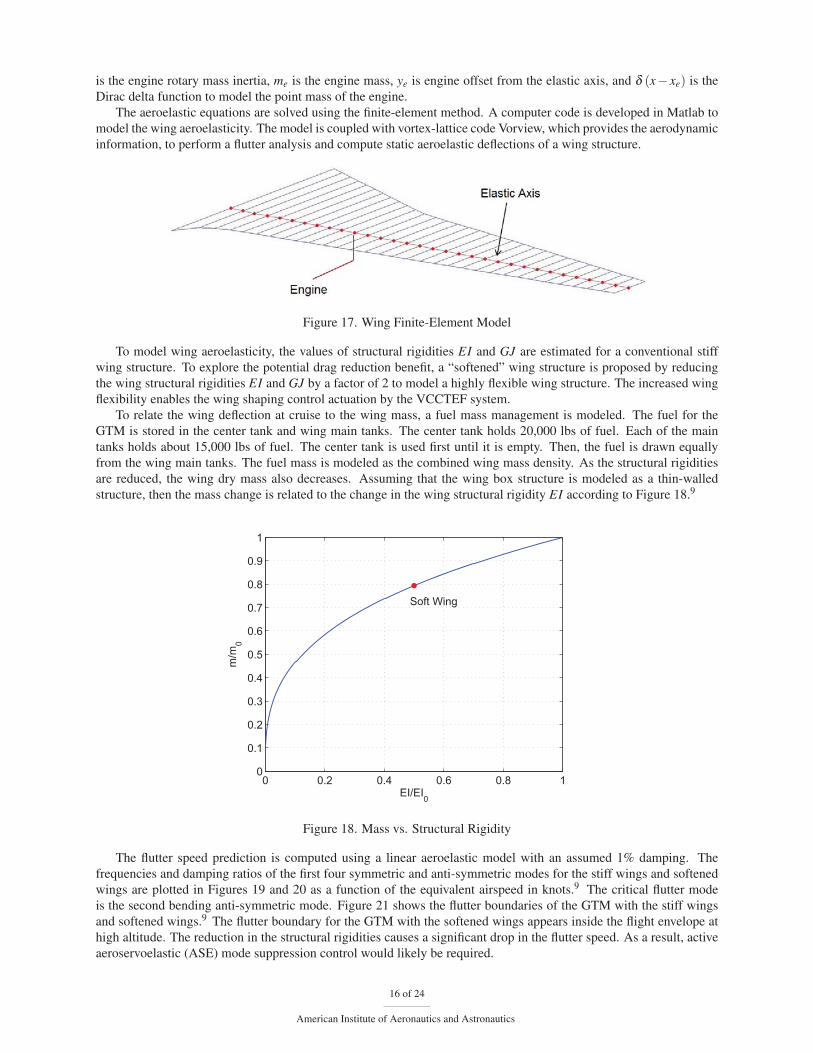
The aeroelastic equations are solved using the finite-element method. A computer code is developed in Matlab to
model the wing aeroelasticity. The model is coupled with vortex-lattice code Vorview, which provides the aerodynamic
information, to perform a flutter analysis and compute static aeroelastic deflections of a wing structure.
Figure 17. Wing Finite-Element Model
To model wing aeroelasticity, the values of structural rigidities EI and GJ are estimated for a conventional stiff
wing structure. To explore the potential drag reduction benefit, a “softened” wing structure is proposed by reducing
the wing structural rigidities EI and GJ by a factor of 2 to model a highly flexible wing structure. The increased wing
flexibility enables the wing shaping control actuation by the VCCTEF system.
To relate the wing deflection at cruise to the wing mass, a fuel mass management is modeled. The fuel for the
GTM is stored in the center tank and wing main tanks. The center tank holds 20,000 lbs of fuel. Each of the main
tanks holds about 15,000 lbs of fuel. The center tank is used first until it is empty. Then, the fuel is drawn equally
from the wing main tanks. The fuel mass is modeled as the combined wing mass density. As the structural rigidities
are reduced, the wing dry mass also decreases. Assuming that the wing box structure is modeled as a thin-walled
structure, then the mass change is related to the change in the wing structural rigidity EI according to Figure 18.9
0 0.2 0.4 0.6 0.8 10
0.1
0.2
0.3
0.4
0.5
0.6
0.7
0.8
0.9
1
EI/EI0
m/m
0
Soft Wing
Figure 18. Mass vs. Structural Rigidity
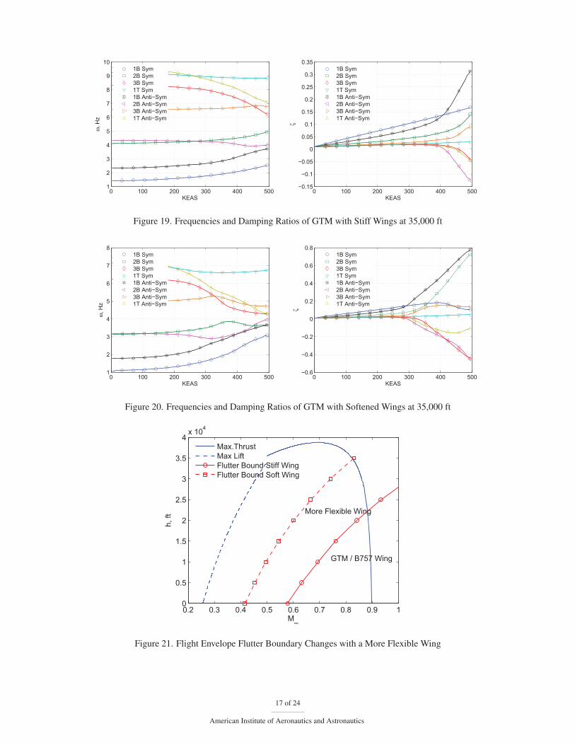
The flutter speed prediction is computed using a linear aeroelastic model with an assumed 1% damping. The
frequencies and damping ratios of the first four symmetric and anti-symmetric modes for the stiff wings and softened
wings are plotted in Figures 19 and 20 as a function of the equivalent airspeed in knots.9 The critical flutter mode
is the second bending anti-symmetric mode. Figure 21 shows the flutter boundaries of the GTM with the stiff wings
and softened wings.9 The flutter boundary for the GTM with the softened wings appears inside the flight envelope at
high altitude. The reduction in the structural rigidities causes a significant drop in the flutter speed. As a result, active
aeroservoelastic (ASE) mode suppression control would likely be required.
16 of 24
American Institute of Aeronautics and Astronautics
0 100 200 300 400 5001
2
3
4
5
6
7
8
9
10
KEAS
ω, H
z
1B Sym2B Sym3B Sym1T Sym1B Anti−Sym2B Anti−Sym3B Anti−Sym1T Anti−Sym
0 100 200 300 400 500−0.15
−0.1
−0.05
0
0.05
0.1
0.15
0.2
0.25
0.3
0.35
KEAS
ζ
1B Sym2B Sym3B Sym1T Sym1B Anti−Sym2B Anti−Sym3B Anti−Sym1T Anti−Sym
Figure 19. Frequencies and Damping Ratios of GTM with Stiff Wings at 35,000 ft
0 100 200 300 400 5001
2
3
4
5
6
7
8
ω, H
z
KEAS
1B Sym2B Sym3B Sym1T Sym1B Anti−Sym2B Anti−Sym3B Anti−Sym1T Anti−Sym
0 100 200 300 400 500−0.6
−0.4
−0.2
0
0.2
0.4
0.6
0.8
KEAS
ζ
1B Sym2B Sym3B Sym1T Sym1B Anti−Sym2B Anti−Sym3B Anti−Sym1T Anti−Sym
Figure 20. Frequencies and Damping Ratios of GTM with Softened Wings at 35,000 ft
0.2 0.3 0.4 0.5 0.6 0.7 0.8 0.9 10
0.5
1
1.5
2
2.5
3
3.5
4x 10⁴
M∞
h, ft
Max.ThrustMax LiftFlutter Bound Stiff WingFlutter Bound Soft Wing
GTM / B757 Wing
More Flexible Wing
Figure 21. Flight Envelope Flutter Boundary Changes with a More Flexible Wing
17 of 24
American Institute of Aeronautics and Astronautics
IX. Aerodynamic Modeling
A. Skin Friction Drag Estimation
Vortex-lattice code Vorview is used to conduct aerodynamic modeling and analysis. Due to the inherent limitation of
the vortex-lattice method, Vorview only computes induced drag component. To analyze the drag reduction benefit, a
skin friction drag correction is implemented. Wave drag due to compressibility effect can be analyzed by CFD which
will be studied in the future. Assuming the cruise condition is reasonably far from the drag divergence Mach number,
then the wave drag component may be neglected in the initial analysis.
Currently, the calculation of viscous drag, using an approximate method to estimate skin friction as described by
Abbott and Von Doenhoff,10 in the process of being added to Vorview. This section describes the method, as well as
correlation of preliminary results with previously published data.
The following relationships form the basis for approximating viscous drag:
CD f ,wing = kc fSwwing
Sre f(40)
CD f , f uselage = Kc fSw f uselage
Sre f(41)
The key parameters in these expressions are the calculation of skin friction coefficient, c f , and the corresponding
form factors for airfoil, k, and fuselage, K, shapes. The airfoil form factor k is given by Reference11 as a function of
the thickness-to-chord ratio t/c, Mach number M, and wing sweep angle Λ . The fuselage (body) form factor K is
given by Reference12 as a function of the fineness ratio l/d and Mach number M .
The calculation of skin friction coefficient associated with the wing and fuselage is performed using one side of a
flat plate approximation. The resulting expression for c f that captures the effect of laminar-to-turbulent flow transition
is as follows:
c f =Xc
c
(1.328Re−0.5
Xc
)+(0.072Re−0.2
c)− Xc
c
(0.072Re−0.2
Xc
)(42)
where Rec is the Reynolds number based on the mean aerodynamic chord.
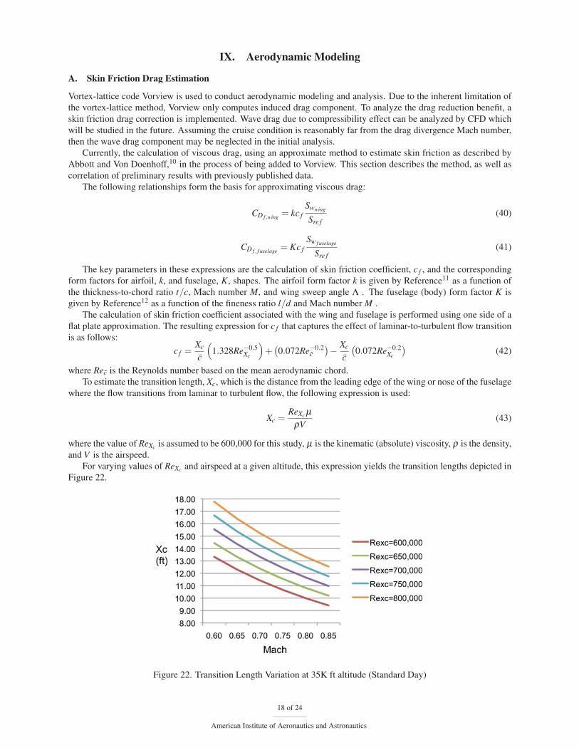
To estimate the transition length, Xc, which is the distance from the leading edge of the wing or nose of the fuselage
where the flow transitions from laminar to turbulent flow, the following expression is used:
Xc =ReXc μ
ρV(43)
where the value of ReXc is assumed to be 600,000 for this study, μ is the kinematic (absolute) viscosity, ρ is the density,
and V is the airspeed.
For varying values of ReXc and airspeed at a given altitude, this expression yields the transition lengths depicted in
Figure 22.
Figure 22. Transition Length Variation at 35K ft altitude (Standard Day)
18 of 24
American Institute of Aeronautics and Astronautics
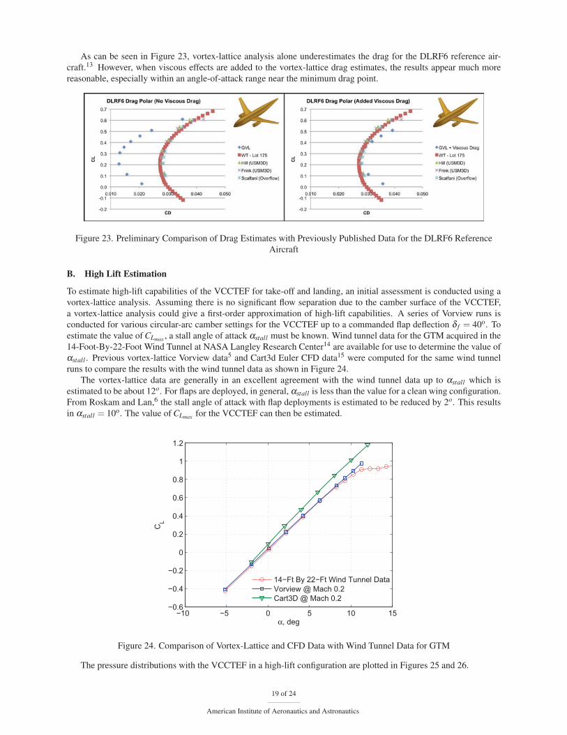
As can be seen in Figure 23, vortex-lattice analysis alone underestimates the drag for the DLRF6 reference air-
craft.13 However, when viscous effects are added to the vortex-lattice drag estimates, the results appear much more
reasonable, especially within an angle-of-attack range near the minimum drag point.
Figure 23. Preliminary Comparison of Drag Estimates with Previously Published Data for the DLRF6 Reference
Aircraft
B. High Lift Estimation
To estimate high-lift capabilities of the VCCTEF for take-off and landing, an initial assessment is conducted using a
vortex-lattice analysis. Assuming there is no significant flow separation due to the camber surface of the VCCTEF,
a vortex-lattice analysis could give a first-order approximation of high-lift capabilities. A series of Vorview runs is
conducted for various circular-arc camber settings for the VCCTEF up to a commanded flap deflection δ f = 40o. To
estimate the value of CLmax , a stall angle of attack αstall must be known. Wind tunnel data for the GTM acquired in the
14-Foot-By-22-Foot Wind Tunnel at NASA Langley Research Center14 are available for use to determine the value of
αstall . Previous vortex-lattice Vorview data5 and Cart3d Euler CFD data15 were computed for the same wind tunnel
runs to compare the results with the wind tunnel data as shown in Figure 24.
The vortex-lattice data are generally in an excellent agreement with the wind tunnel data up to αstall which is
estimated to be about 12o. For flaps are deployed, in general, αstall is less than the value for a clean wing configuration.
From Roskam and Lan,6 the stall angle of attack with flap deployments is estimated to be reduced by 2o. This results
in αstall = 10o. The value of CLmax for the VCCTEF can then be estimated.
−10 −5 0 5 10 15−0.6
−0.4
−0.2
0
0.2
0.4
0.6
0.8
1
1.2
α, deg
CL
14−Ft By 22−Ft Wind Tunnel DataVorview @ Mach 0.2Cart3D @ Mach 0.2
Figure 24. Comparison of Vortex-Lattice and CFD Data with Wind Tunnel Data for GTM
The pressure distributions with the VCCTEF in a high-lift configuration are plotted in Figures 25 and 26.
19 of 24
American Institute of Aeronautics and Astronautics

Figure 25. Pressure Distribution on Upper Wing Surface with VCCTEF at δ f = 40o
Figure 26. Pressure Distribution on Lower Wing Surface with VCCTEF at δ f = 40o
0 2 4 6 8 100
0.2
0.4
0.6
0.8
1
1.2
1.4
1.6
1.8
2
α, deg
CL
δ= 0o
δ=10o
δ=20o
δ=30o
δ=40o
δ=40o w/ 54" Inboard Chord
Figure 27. Lift Curves of GTM with VCCTEF
20 of 24
American Institute of Aeronautics and Astronautics
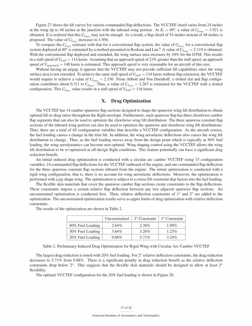
Figure 27 shows the lift curves for various commanded flap deflections. The VCCTEF chord varies from 24 inches
at the wing tip to 48 inches at the junction with the inboard wing portion. At δ f = 40o, a value of CLmax = 1.921 is
obtained. It is realized that this CLmax may not be enough. As a result, a flap chord of 54 inches instead of 48 inches is
proposed. The value of CLmax increases to 1.956.
To compare the CLmax estimate with that for a conventional flap system, the value of CLmax for a conventional flap
system deployed at 40o is estimated by a method presented in Roskam and Lan.6 A value of CLmax = 2.119 is obtained.
With the conventional flap deployed and extended, the wing surface area increases by 10% for the GTM. This results
in a stall speed of Vstall = 114 knots. Assuming that an approach speed of 23% greater than the stall speed, an approach
speed of Vapproach = 140 knots is estimated. This approach speed is very reasonable for an aircraft of this size.
Without having an airgap, it appears that the VCCTEF may not provide sufficient lift capabilities since the wing
surface area is not extended. To achieve the same stall speed of Vstall = 114 knots without flap extension, the VCCTEF
would require to achieve a value of CLmax = 2.330. From Abbott and Von Doenhoff, a slotted slat and flap configu-
ration contributes about 0.311 to CLmax . Thus, a value of CLmax = 2.267 is estimated for the VCCTEF with a slotted
configuration. This CLmax value results in a stall speed of Vstall = 116 knots.
X. Drag Optimization
The VCCTEF has 14 camber spanwise flap sections designed to shape the spanwise wing lift distribution to obtain
optimal lift-to-drag ratios throughout the flight envelope. Furthermore, each spanwise flap has three chordwise camber
flap segments that can also be used to optimize the chordwise wing lift distribution. The three spanwise constant flap
sections of the inboard wing portion can also be used to optimize the spanwise and chordwise wing lift distributions.
Thus, there are a total of 45 configuration variables that describe a VCCTEF configuration. As the aircraft cruises,
the fuel loading causes a change in the trim lift. In addition, the wing aeroelastic deflections also causes the wing lift
distribution to change. Thus, as the fuel loading moves away from the design point which is typically at 50% fuel
loading, the wing aerodynamics can become non-optimal. Wing shaping control using the VCCTEF allows the wing
lift distribution to be re-optimized at off-design flight conditions. This feature potentially can have a significant drag
reduction benefit.
An initial induced drag optimization is conducted with a circular arc camber VCCTEF using 15 configuration
variables; 14 commanded flap deflections for the VCCTEF outboard of the engine, and one commanded flap deflection
for the three spanwise constant flap sections inboard from the engine. The initial optimization is conducted with a
rigid wing configuration, that is, there is no account for wing aeroelastic deflections. Moreover, the optimization is
performed with a jig-shape wing. The optimization is subject to a cruise lift constraint that factors into the fuel loading.
The flexible skin materials that cover the spanwise camber flap sections create constraints to the flap deflections.
These constraints impose a certain relative flap deflection between any two adjacent spanwise flap sections. An
unconstrained optimization is conducted first. Then, relative deflection constraints of 1o and 2o are added to the
optimization. The unconstrained optimization results serve as upper limits of drag optimization with relative deflection
constraints.
The results of the optimization are shown in Table 2.
Unconstrained 2o Constraint 1o Constraint
80% Fuel Loading 2.64% 2.38% 1.99%
50% Fuel Loading 3.64% 3.26% 1.23%
20% Fuel Loading 9.88% 5.71% 3.24%
Table 2. Preliminary Induced Drag Optimization for Rigid Wing with Circular Arc Camber VCCTEF
The largest drag reduction is noted with 20% fuel loading. For 2o relative deflection constraints, the drag reduction
decreases to 5.71% from 9.88%. There is a significant penalty in drag reduction benefit as the relative deflection
constraints drop below 2o. This suggests that the flexible skin materials should be designed to allow at least 2o
flexibility.
The optimal VCCTEF configuration for the 20% fuel loading is shown in Figure 28.
21 of 24
American Institute of Aeronautics and Astronautics
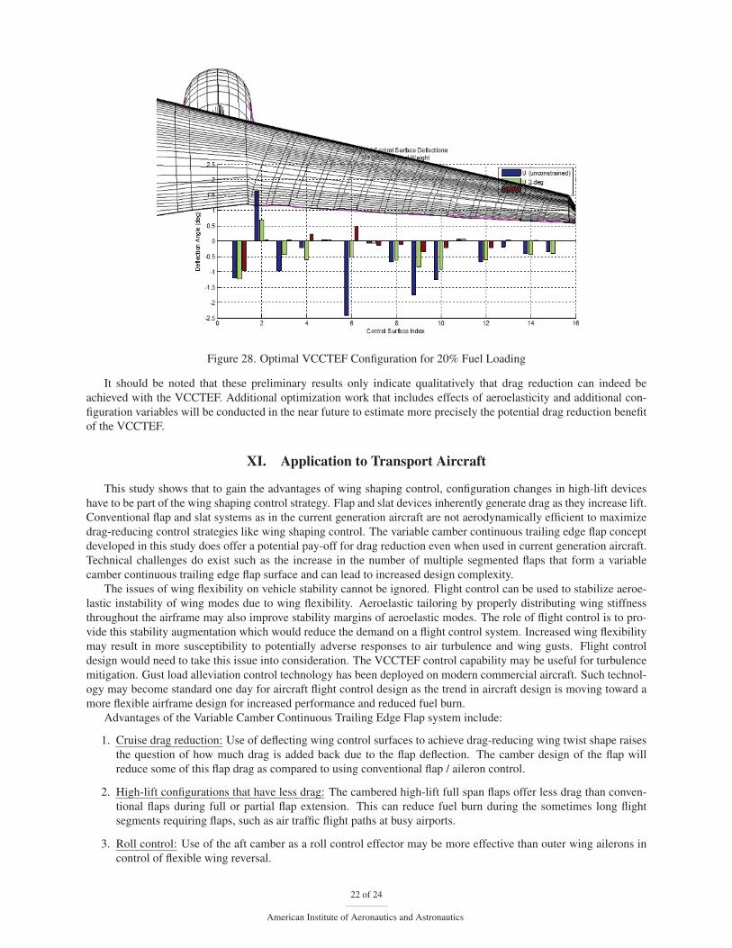
Figure 28. Optimal VCCTEF Configuration for 20% Fuel Loading
It should be noted that these preliminary results only indicate qualitatively that drag reduction can indeed be
achieved with the VCCTEF. Additional optimization work that includes effects of aeroelasticity and additional con-
figuration variables will be conducted in the near future to estimate more precisely the potential drag reduction benefit
of the VCCTEF.
XI. Application to Transport Aircraft
This study shows that to gain the advantages of wing shaping control, configuration changes in high-lift devices
have to be part of the wing shaping control strategy. Flap and slat devices inherently generate drag as they increase lift.
Conventional flap and slat systems as in the current generation aircraft are not aerodynamically efficient to maximize
drag-reducing control strategies like wing shaping control. The variable camber continuous trailing edge flap concept
developed in this study does offer a potential pay-off for drag reduction even when used in current generation aircraft.
Technical challenges do exist such as the increase in the number of multiple segmented flaps that form a variable
camber continuous trailing edge flap surface and can lead to increased design complexity.
The issues of wing flexibility on vehicle stability cannot be ignored. Flight control can be used to stabilize aeroe-
lastic instability of wing modes due to wing flexibility. Aeroelastic tailoring by properly distributing wing stiffness
throughout the airframe may also improve stability margins of aeroelastic modes. The role of flight control is to pro-
vide this stability augmentation which would reduce the demand on a flight control system. Increased wing flexibility
may result in more susceptibility to potentially adverse responses to air turbulence and wing gusts. Flight control
design would need to take this issue into consideration. The VCCTEF control capability may be useful for turbulence
mitigation. Gust load alleviation control technology has been deployed on modern commercial aircraft. Such technol-
ogy may become standard one day for aircraft flight control design as the trend in aircraft design is moving toward a
more flexible airframe design for increased performance and reduced fuel burn.
Advantages of the Variable Camber Continuous Trailing Edge Flap system include:
1. Cruise drag reduction: Use of deflecting wing control surfaces to achieve drag-reducing wing twist shape raises
the question of how much drag is added back due to the flap deflection. The camber design of the flap will
reduce some of this flap drag as compared to using conventional flap / aileron control.
2. High-lift configurations that have less drag: The cambered high-lift full span flaps offer less drag than conven-
tional flaps during full or partial flap extension. This can reduce fuel burn during the sometimes long flight
segments requiring flaps, such as air traffic flight paths at busy airports.
3. Roll control: Use of the aft camber as a roll control effector may be more effective than outer wing ailerons in
control of flexible wing reversal.
22 of 24
American Institute of Aeronautics and Astronautics
4. Stabilization of wing dynamic modes: The third or aft camber section can be used to suppress wing dynamic
modes, having sufficient bandpass for this control. Moreover, the control input can be distributed along the span
of the wing, making the suppression more effective.
5. Weight savings for flap actuation components: Two advantages for weight savings with the VCCTEF system
are: 1) Shape Memory Alloy actuators have much less weight compared with electric or hydraulic actuation;
exceeding better than a 10:1 advantage; and 2) the VCCTEF uses hinge line rotary actuators, thereby eliminating
the need for bell-cranks and heavy screw-jack actuators with external mounting and pod covers. This can result
in a weight savings of between 250 and 500 lbs. per wing.
XII. Conclusion
The Variable Camber Continuous Trailing Edge Flap has excellent potential to achieve energy goals for future N+3
transports. The trend for lighter and more flexible wing structures can be leveraged to upgrading structural shape to
meet combined aerodynamic and aeroelastic continuous wing shaping for drag reduction. Adding new technology of
Shape Memory Alloy actuation results in much lighter weights for flap control components. Factoring in continuous
camber flaps eliminates drag-inducing gaps between wing control surfaces, and also can significantly reduce noise due
to these gaps.
This combination of aeroelastic and aerodynamic properties that results in performance improvement is a good
example of effective Multidisciplinary Design Analysis and Optimization (MDAO) system development. Program
results also project the need for verification of interactive aeroelastic and aerodynamic modeling; this being best
achieved by wind tunnel tests of flexible wing models with variable camber control surfaces. Flight development
on flexible wing test vehicles would further refine and verify the control of the flexible wing, especially control of
possible flutter excitations. Boeing and NASA are continuing exploring this VCCTEF concept using a more flexible
wing configured in the Generic Transport Model based on the B757, with wing flexible properties closer to current
transport (i.e., B787) wing designs.
Acknowledgment
The authors wish to acknowledge Mr. John Dykman, Mr. Dan Clingman, Mr. Charles Morris, and Mr. Jim
Sheahan from Boeing for technical support in design and aeroelastic model development. The authors also want
to thank the NASA Aeronautics Research Mission Directorate (ARMD) Fixed Wing Project under the Fundamental
Aeronautics Program for providing the funding support for this work.
References1Nguyen, N., “Elastically Shaped Future Air Vehicle Concept,” NASA Innovation Fund Award 2010 Report, October 2010, Submitted to
NASA Innovative Partnerships Program.2Boeing Report No. 2012X0015, “Development of Variable Camber Continuous Trailing Edge Flap System,” October 4, 2012.3Jordan, T. L., Langford, W. M., Belcastro, C. M., Foster, J. M., Shah, G. H., Howland, G., and Kidd, R., “Development of a Dynamically
Scaled Generic Transport Model Testbed for Flight Research Experiments,” AUVSI Unmanned Unlimited, Arlington, VA, 2004.4Miranda, L.R., Elliot, R.D., and Baker, W.M., “A Generalized Vortex Lattice Method for Subsonic and Supersonic Flow Applications,”
NASA CR-2865, 1977.5Nguyen, N., Nelson, A., and Pulliam, T., “Damage Adaptive Control System Research Report,” Internal NASA Report, April 2006.6Roskam and Lan, Airplane Aerodynamics and Performance, DARcorporation, 1997.7Nguyen, N., Trinh, K., Nguyen, D., Tuzcu, I., “Nonlinear Aeroelasticity of Flexible Wing Structure Coupled with Aircraft Flight Dynamics,”
AIAA Structures, Structural Dynamics, and Materials Conference, AIAA-2012-1792, April 2012.8Theodorsen, T, “General Theory of Aerodynamic Instability and the Mechanism of Flutter”, NACA Report 496, 1935.9Nguyen, N., Urnes, J., “Aeroelastic Modeling of Elastically Shaped Aircraft Concept via Wing Shaping Control for Drag Reduction," AIAA
Atmospheric Flight Mechanics Conference, AIAA-2012-4642, August 2012.10Abbott, I. H. and Von Doenhoff, A. E., Theory of Wing Sections, Dover Publications, Inc., New York, pp. 97-103.11Stanford University, AA241, http://adg.stanford.edu/aa241/drag/lsformfactor.html12Stanford University, AA241, http://adg.stanford.edu/aa241/drag/BODYFORMFACTOR.HTML13Hill, G., “Aerodynamic and Acoustic Investigations of an Advanced Over-the-Wing Nacelle Transport Aircraft Configuration,” M.S. Thesis,
Old Dominion University, May, 2007 (p. 35, Fig. 6).14Shah, G. H., ’Aerodynamic Effects and Modeling of Damage to Transport Aircraft,” AIAA Atmospheric Flight Mechanics Conference,
AIAA-2008-6203, August 2008.
23 of 24
American Institute of Aeronautics and Astronautics

15Aftosmis, M. J., Berger, M. J., and Melton, J. E., “Robust and Efficient CartesianMesh Generation for Component- Based Geometry,” AIAA
Journal, Vol. 36, No. 6, 1998, pp. 953-960.
24 of 24
American Institute of Aeronautics and Astronautics