development of the nasa high-altitude imaging wind and
TRANSCRIPT

1
Development of the NASA High-Altitude Imaging Wind and Rain Airborne Profiler
Lihua Li1, Gerald Heymsfield1, James Carswell2, Dan Schaubert3,
Matthew McLinden1, Manuel Vega1, Martin Perrine1 1NASA Goddard Space Flight Center, Greenbelt, MD 20771, 301-614-6356, [email protected]
2Remote Sensing Solutions, Barnstable, MA 3University of Massachusetts, Amherst, MA
Asbtract ⎯ The scope of this paper1 is the development and recent field deployments of the High-Altitude Imaging Wind and Rain Airborne Profiler (HIWRAP), which was funded under the NASA Instrument Incubator Program (IIP) [1]. HIWRAP is a dual-frequency (Ka- and Ku-band), dual-beam (300 and 400 incidence angles), conical scanning, Doppler radar system designed for operation on the NASA high-altitude (65,000 ft) Global Hawk Unmanned Aerial System (UAS). It utilizes solid state transmitters along with a novel pulse compression scheme that results in a system with compact size, light weight, less power consumption, and low cost compared to radars currently in use for precipitation and Doppler wind measurements. By combining measurements at Ku- and Ka-band, HIWRAP is able to image winds through measuring volume backscattering from clouds and precipitation. In addition, HIWRAP is also capable of measuring surface winds in an approach similar to SeaWinds on QuikScat. To this end, HIWRAP hardware and software development has been completed. It was installed on the NASA WB57 for instrument test flights in March, 2010 and then deployed on the NASA Global Hawk for supporting the Genesis and Rapid Intensification Processes (GRIP) field campaign in August-September, 2010. This paper describes the scientific motivations of the development of HIWRAP as well as system hardware, aircraft integration and flight missions. Preliminary data from GRIP science flights is also presented.
TABLE OF CONTENTS
1. INTRODUCTION ................................................. 1 2. MEASUREMENT CONCEPT ................................. 2 3. SYSTEM DESCRIPTION ....................................... 2 4. FIELD MISSIONS ................................................ 5 5. FUTURE PLAN ................................................... 7 REFERENCES ......................................................... 7 BIOGRAPHY .......................................................... 7
1. INTRODUCTION
Extreme weather events including tropical storms pose significant natural threats to coastal areas and maritime
1 978-1-4244-7351-9/11/$26.00 ©2011 IEEE. 2 IEEEAC paper#1277, Version 1, Updated 2010:10:26
interests. High spatial and temporal resolution 3-dimensional wind measurements are critically needed for tropical cyclone research and for improvement in hurricane intensity forecasting. In the case of tropical cyclones and severe ocean storms, measurements of the atmospheric and tropospheric winds are often sparse. Satellite instruments to date cannot fully overcome this difficulty. Though QuikSat (scatterometer) and WindSat (radiometer) provide wind measurements on a global scale, they are limited to ocean surface wind measurements in precipitation-free regions. Use of spaceborne radar Doppler wind retrieval would overcome these limitations considerably, but technical challenges have not been fully overcome [2][3]. Furthermore, spaceborne platforms have the inherent obstacles of low spatial resolution, short dwell time and long revisit time for providing critical information on rapidly developing weather events such as hurricanes in coastal regions. Measurements of atmospheric winds using airborne radars have filled this critical data gap, and have been essential to the understanding of various weather events such as tropical storms, and to the subsequent improvement of parameterizations in forecast models [4]. Tropical storms are often located in remote regions of the ocean, making manned aircraft impractical because of their limited endurance. Along with the development of new technologies, NASA’s interests have more recently focused on UAS, especially high altitude, long endurance platforms (HALE UAS), such as the Northrop Grumman Global Hawk. Wind and precipitation measurements from high-altitude aircraft, especially long-duration UAS are highly desirable since they provide focused measurements with higher spatial and temporal sampling. Global Hawk UAS, instrumented with remote sensors, has the potential to provide repeated passes over tropical cyclones with the data sets critically needed for improved understanding and forecasting of these weather events. Through the support of the NASA IIP program, NASA Goddard Space Flight Center (GSFC) has teamed with Remote Sensing Solutions and the University of Massachusetts, Amherst to design and develop the innovative HIWRAP system. Theoretical and experimental research done by others has provided convincing evidence that airborne or spaceborne conical scanning radars can provide the full horizontal wind vector in precipitation and cloud regions [5][6]. By combining conical scan mode

2
measurements at two different frequencies (Ka- and Ku-band) and two different incidence angles (300 and 400), HIWRAP is able to image winds from the surface to cloud top through measuring volume backscattering from clouds and precipitation. HIWRAP technology advances include the development of a compact dual-frequency, dual-beam, conical scan antenna system; development of solid-state transmitter based transceivers that are capable of transmitting/receiving versatile waveforms and achieving performance comparable to high peak power tube-based systems; and development of a high-speed digital receiver and processor to handle the complex receiving pulse sequences and high data rates resulting from multi receiver channels and conical scan. In the following sections, we provide a brief review of the HIWRAP wind measurement concept and the measurement requirements, and then describe the HIWRAP system hardware and software development. Finally, we discuss HIWRAP installation, test flights and science flights on the NASA WB-57 and the Global Hawk.
2. MEASUREMENT CONCEPT
HIWRAP is designed to measure tropospheric winds by collecting Doppler profiles from cloud and precipitation volume backscattering measurements. With the use of Ka-band, HIWRAP is significantly more sensitive to cloud particles than lower frequency radars, enabling it to measure the mean cloud particle velocity and thus map the 3D tropospheric winds. In addition, its dual-frequency operation enables it to map the full atmospheric boundary layer winds, derive information about the drop-size distribution of the precipitation, and estimate the ocean surface wind field using ocean wind scatterometry techniques similar to these employed by QuikScat. HIWRAP operating frequencies are near to those used by the NASA Global Precipitation Measurement Dual-frequency Precipitation Radar (DPR). Therefore, HIWRAP is also capable of providing airborne validation data for GPM. As shown in Figure 1, HIWRAP transmits and receives two Ku-band beams (30o and 40o) and two Ka-band beams (30o and 40o), simultaneously. By scanning the antenna around the vertical axis, these beams will sweep through the volume beneath the aircraft and simultaneously make measurements of Doppler/reflectivity profiles from each beam. Illustrated as Figure 2, for any given volume cell within the inner swath, HIWRAP will view this cell at both Ku and Ka-band from two different incidence angles and four different azimuth angles (forward and backward looking while the aircraft flies over the cell), from which the 3 components of the wind will be derived. Due to aircraft ground speed and storm system winds, Doppler measurements are potentially folded for some volume cells. Different techniques, such as geometry correction, dual pulse repetition frequency (Dual-PRF) and frequency diversity Doppler processing [7], will be used for Doppler
velocity unfolding. The measurement requirements for HIWRAP are given in Table 1 for wind retrievals in 1 km x 1 km x 60 m pixels.
Figure 1. HIWRAP measurement concept
Figure 2. HIWRAP wind field retrieval concept
Table 1 HIWRAP Measurement Requirements
Retrieval Products (resolution cell: 1km x 1km x 60m)
Parameters Range AccuracyHoriz. Wind Speed (ms-1) 0-100 2.0Horiz. Wind Direction (o) 0-360 15Surface Wind Speed (ms-1) 0-60 2.0Surface Wind Direction (o) 0-360 15Vertical Wind Speed (ms-1) ± 20 2.0
3. SYSTEM DESCRIPTION
The design of HIWRAP involved compromises in order to address the scientific requirements and hardware limitations imposed by the size, power, and weight constraints of the Global Hawk platform. A number of factors, such as the high altitude environment, limited space, weight and power posed challenges to the system design. The entire radar

3
system must have the capability to operate in a “turnkey” autonomous operation mode. Table 2 provides performance specifications for HIWRAP, and Figure 3 shows the HIWRAP system block diagram. The radar intermediate frequency and local oscillator (IF/LO), RF transceivers and the digital receiver and processor subsystems are mounted on a rotating structure that typically spins at 15 rpm (Figure 4). These enclosures are not pressurized. Cooling of the power amplifiers is done by using heat pipes, heat sinks and fans. The data system, power distribution, navigation unit
and the scanner controller are installed in the stationary payload areas on the aircraft. This configuration avoids the use of long waveguides and a multi-channel RF rotary joint, which is lossy and difficult to build and maintain at HIWRAP frequencies. Figure 5 shows the HIWRAP scanner assembly installed in Global Hawk payload Zone 25 (belly radome area). The following provides a brief description of the key subsystems.
Figure 3. HIWRAP system block diagram
Table 2 HIWRAP System Specifications
Parameters
Specifications
Ku-band Ka-band
RF Frequency (GHz) Inner Beam: 13.910 Outer Beam: 13.470
Inner Beam: 35.560 Outer Beam: 33.720
Tx Peak Power (W) 25 43 dB Beam Width (o) 2.9 1.2Polarization V (inner beam), H (outer
beam) Min. Detect. Reflectivity (dBZe, 60 m range res., 10 km range and 3 km chirp pulse)
0.0 -5.0
Dynamic Range (dB) > 65 Doppler Velocity (ms-1) 0-150 (Accuracy < 1.5 ms-1 for
SNR>10) Scanning Conical Scan, 10-30 rpm
Figure 4. HIWRAP scanner assembly

4
Figure 5. HIWRAP configuration in Global Hawk
Antenna
The HIWRAP’s antenna subsystem was designed by the University of Massachusetts at Amherst [8]. It consists of a single offset parabolic reflector and two dual-frequency feed horns to form the 30o and 40o beams. The dual-frequency feed utilizes a dielectric rod for the Ka-band signal and a corrugated horn for the Ku-band signal. This novel antenna design meets a number of challenging requirements including limited space on the Global Hawk payload area, dual-looking angles and dual-frequency operation at each angle. Figure 6 shows the antenna hardware while Figure 7 gives the Ka and Ku band antenna patterns in the elevation plane.
Figure 6. HIWRAP antenna (a) main reflector; (b) antenna
assembly on the flight frame; (c) one of the dual-frequency feed.
Transceivers HIWRAP utilizes a dual-frequency compact transceiver that is modular in design. This transceiver supports versatile digital pulse compression through the use of inexpensive direct digital synthesizer (DDS) chips for transmit waveform generation. The design supports simultaneous operation at two center frequencies at each band, and two incidence angles in order to maintain high temporal and spatial resolution. Innovative approaches are taken to enhance independent sample rates and utilize the maximum duty cycle that the power amplifiers can deliver. At each frequency band (Ka or Ku), both upper and lower side band mixing products in the RF up-conversion stage are used to
produce the two RF channels to form the two beams. As such, this design only needs one RF local oscillator for Ka (or Ku) subsystem, and thus saves on space, power consumption and weight.
Figure 7. HIWRAP antenna pattern: (a) Ka-band elevation,
(b) Ku-band elevation. Elevation axis shifted to midway between beams.
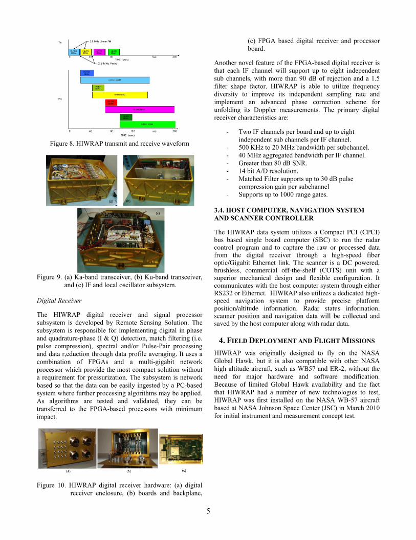
HIWRAP uses commercial solid state power amplifiers as its transmitters. The Ku-band subsystem utilizes a single unit power amplifier that delivers 25 W peak power, while the Ka-band subsystem uses a power combining amplifier assembly that produces 4W peak power for each beam. A DDS based custom board was developed to produce the transmit waveform and timing control signals. The combination of DDS along with field programmable gate array (FPGA) technologies enabled the software controlled, versatile waveform generation needed to achieve, frequency modulation, frequency diversity and amplitude modulation, as well as synchronized radar timing control. An internal calibration loop provides an accurate measurement of the total transceiver gain to within 0.2 dB or better and samples the transmit waveform so that pre-distortion techniques can be used to improve pulse compression range sidelobe performance. Figure 8 shows a typical HIWRAP transmit and receive waveform cycle. Figure 9 shows the Ka- and Ku-band transceivers, and the IF and local oscillator subsystems.
5
Figure 8. HIWRAP transmit and receive waveform
Figure 9. (a) Ka-band transceiver, (b) Ku-band transceiver,
and (c) IF and local oscillator subsystem. Digital Receiver
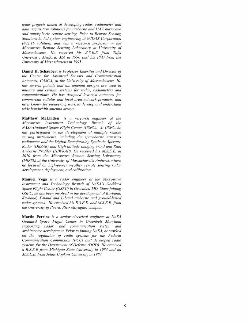
The HIWRAP digital receiver and signal processor subsystem is developed by Remote Sensing Solution. The subsystem is responsible for implementing digital in-phase and quadrature-phase (I & Q) detection, match filtering (i.e. pulse compression), spectral and/or Pulse-Pair processing and data r,eduction through data profile averaging. It uses a combination of FPGAs and a multi-gigabit network processor which provide the most compact solution without a requirement for pressurization. The subsystem is network based so that the data can be easily ingested by a PC-based system where further processing algorithms may be applied. As algorithms are tested and validated, they can be transferred to the FPGA-based processors with minimum impact.
Figure 10. HIWRAP digital receiver hardware: (a) digital receiver enclosure, (b) boards and backplane,
(c) FPGA based digital receiver and processor board.
Another novel feature of the FPGA-based digital receiver is that each IF channel will support up to eight independent sub channels, with more than 90 dB of rejection and a 1.5 filter shape factor. HIWRAP is able to utilize frequency diversity to improve its independent sampling rate and implement an advanced phase correction scheme for unfolding its Doppler measurements. The primary digital receiver characteristics are:
- Two IF channels per board and up to eight independent sub channels per IF channel.
- 500 KHz to 20 MHz bandwidth per subchannel. - 40 MHz aggregated bandwidth per IF channel. - Greater than 80 dB SNR. - 14 bit A/D resolution. - Matched Filter supports up to 30 dB pulse
compression gain per subchannel - Supports up to 1000 range gates.
3.4. HOST COMPUTER, NAVIGATION SYSTEM AND SCANNER CONTROLLER
The HIWRAP data system utilizes a Compact PCI (CPCI) bus based single board computer (SBC) to run the radar control program and to capture the raw or processed data from the digital receiver through a high-speed fiber optic/Gigabit Ethernet link. The scanner is a DC powered, brushless, commercial off-the-shelf (COTS) unit with a superior mechanical design and flexible configuration. It communicates with the host computer system through either RS232 or Ethernet. HIWRAP also utilizes a dedicated high-speed navigation system to provide precise platform position/altitude information. Radar status information, scanner position and navigation data will be collected and saved by the host computer along with radar data.
4. FIELD DEPLOYMENT AND FLIGHT MISSIONS
HIWRAP was originally designed to fly on the NASA Global Hawk, but it is also compatible with other NASA high altitude aircraft, such as WB57 and ER-2, without the need for major hardware and software modification. Because of limited Global Hawk availability and the fact that HIWRAP had a number of new technologies to test, HIWRAP was first installed on the NASA WB-57 aircraft based at NASA Johnson Space Center (JSC) in March 2010 for initial instrument and measurement concept test.

6
Figure 11. HIWRAP installation on NASA WB57 Figure 11 shows a concept drawing for HIWRAP installation in a 6-foot pallet on the WB-57. The test flights (~2 to 4 hours each) on WB57 proved that HIWRAP mechanical hardware, thermal control and radar electronics performed well at high altitude environment, and provided valuable information for preparing the radar for Global Hawk flights.
After the WB57 test flights, efforts were switched to integrate HIWRAP on Global Hawk so that it could be ready for the GRIP science flight mission. The initial installation was started in July 2010. Figure 12 shows the HIWRAP scanner along with radar subsystems installed in the Global Hawk payload Zone 25 while the power distribution unit (PDU) and the data system were installed in payload Zone 12. Figure 13 shows the radome fairing and the dual-frequency radome designed and fabricated by Northrop Grumman.
Figure 12. HIWRAP installation on NASA Global Hawk
Figure 13. HIWRAP Global Hawk radome fairing and radome window
During the GRIP mission, Global Hawk carried out five science flights, including Hurricane Frank on the Pacific coast, Hurricane Earl on the Atlantic east coast, Caribbean Tropical Disturbance, Hurricane Karl in the Gulf of Mexico and Hurricane Matthew in Central America. HIWRAP performed well during these 15 to 25 hour long science flights. Figure 14 is a satellite image of Hurricane Matthew and showing the Global Hawk flight track during the flight on September 25, 2010. Figure 15 shows the uncalibrated backscattering power measured by the Ka inner beam and Ku inner beam channels (20 μs/1MHz linear chirp) through four azimuth scan cycles. Both images show the precipitation region at low altitude and cloud layer up high as well as surface return at 23 km slant range. The variation in the range of the surface return was due to the non-zero aircraft pitch angle. The Ka-band image also indicates strong attenuation from precipitation. As a result, the surface return was not seen by this frequency in these regions.
Figure 14. Satellite image of Hurricane Matthew (September
25, 2010) and Global Hawk flight track.

7
Figure 15. Preliminary images of uncalibrated
backscattering power (a) Ka inner beam, (b) Ku inner beam. Both beams were operated with 20 μs/1MHz linear chirp mode.
5. FUTURE PLANS
HIWRAP system post-flight calibration and data processing are under the way. Meanwhile, HIWRAP will be configured in fixed nadir pointing mode and installed on the NASA ER-2 for NASA GPM pre-launch ground validation flight mission, Midlatitude Continental Convective Cloud Experiment (MC3E), which will be held at the Department of Energy (DOE) Atmospheric Radiation Measurement (ARM) climate research facility in north-central Oklahoma during April-May 2011. In addition, HIWRAP will fly on the Global Hawk in support of the NASA Venture Class mission Hurricane and Severe Storm Sentinel (HS3) missions from year 2012 to 2014. Acknowledgement This work was funded under the NASA Instrument Incubator Program funding. Thanks to Dr. Justin Creticos for the design of the antenna through his Ph.D program.
REFERENCES [1] G.M. Heymsfield, J. Carswell, High Altitude Imaging Wind
and Rain Radar (HIWRAP). , NASA Science Technology Conference 2008 (NSTC2008).
[2] Marks, F. D., Houze R.A., Inner core structure of hurricane Alicia from airborne Doppler radar observations, Journal of the Atmospheric Sciences, vol. 44, no. 9, pp. 1296-1317, May 1987
[3] G.M. Heymsfield, S. Bidwell, et al., “The EDOP Radar System on the High Altitude NASA ER-2 Aircraft.”, J. Atmos. Oceanic Tech., 1996, pp 795-809.
[4] Marks, F.D., Shay, L.K and PDT-5, USWRP PDT-5 Report, 1998: Tropical Cyclones: Forecast problems and associated research opportunities. Bull. Amer. Met. Soc., Vol.79, No.2 , 305-323.
[5] R.K. Moore, B. Beh, S. Song. Scanning for a Satellite Radar Wind Sounder (RAWS)” IGARRS ’96 Remote Sensing for Sustainable Future. 1996, pp 996-998.
[6] D. Fernandez, Kerr E., Castells, A., Carswell J., et al., “IWRAP: the Imaging Wind and Rain Airborne Profiler for remote sensing of the ocean and the atmospheric boundary layer within tropical cyclones”, IEEE Transactions on Geoscience and Remote Sensing, Vol. 43, No 8, pp. 1775-1787, 2005.
[7] J.R. Carswell, “Final Report: A Revolutionary Wind and Rain Airborne Profiler for Unmanned Aircraft Vehicles”, NASA STTR Final Report, Contract No. NNG05CA96.
[8] J.P. Creticos, Ph.D dissertation, “Development and Design of Dual-band,Multi-function Remote Sensing Antennas”, University of Massachusetts Amherst, 2008.
BIOGRAPHY
Lihua Li is currently a senior research engineer at Goddard Space Flight Center (GSFC) in Greenbelt, MD. At GSFC, he has been the lead engineer for the development of the High-altitude Imaging Wind and Rain Airborne Profiler (HIWRAP) and the ER-2 X-band Radar (EXRAD). He also serves as the instrument scientist for the spaceborne NASA/JAXA GPM Dual-frequency Precipitation Radar (DPR). Before he joined NASA, he was with the Goddard Earth Sciences and Technologies (GEST), University of Maryland Baltimore County. At GEST, his research involved remote sensing radar system development, calibration, field deployment, and data analysis. He was the system engineer for the NASA GSFC 94 GHz Cloud Radar System (CRS) and the 9.6 GHz ER-2 Doppler Radar (EDOP). Prior to GEST, he was a research engineer at the Microwave Remote Sensing Laboratory (MIRSL), University of Massachusetts. He received his B.S.E.E from Tsinghua University, China in 1988, a M. S. from Chinese Academy of Sciences in 1991 and a Ph.D from the University of Massachusetts at Amherst in 2000. Gerry Heymsfield is a senior scientist at Goddard Space Flight Center in Greenbelt, MD where he has been performing science research and high altitude radar development for 28 years. He is Principal Investigator on the EDOP and CRS radars flying on NASA ER-2 aircraft and the new HIWRAP radar. He has been involved with research on precipitation systems including hurricanes and convective systems using information from ground-based and airborne radars and from satellites. He received his M.S. in 1971 from University of Chicago in Geophysical Sciences and his PhD from the University of Oklahoma in Meteorology in 1976. James Carswell is the President/co-founder of Remote Sensing Solutions, a company aimed at bringing advances from the communications, networking and microwave/millimeter-wave industries to remote sensing. He
8
leads projects aimed at developing radar, radiometer and data acquisition solutions for airborne and UAV hurricane and atmospheric remote sensing. Prior to Remote Sensing Solutions he led system engineering at WIDAX Corporation (802.16 solution) and was a research professor in the Microwave Remote Sensing Laboratory at University of Massachusetts. He received his B.S.E.E from Tufts University, Medford, MA in 1990 and his PhD from the University of Massachusetts in 1995. Daniel H. Schaubert is Professor Emeritus and Director of the Center for Advanced Sensors and Communication Antennas, CASCA, at the University of Massachusetts. He has several patents and his antenna designs are used in military and civilian systems for radar, radiometers and communications. He has designed low-cost antennas for commercial cellular and local area network products, and he is known for pioneering work to develop and understand wide bandwidth antenna arrays. Matthew McLinden is a research engineer at the Microwave Instrument Technology Branch of the NASA/Goddard Space Flight Center (GSFC). At GSFC, he has participated in the development of multiple remote sensing instruments, including the spaceborne Aquarius radiometer and the Digital Beamforming Synthetic Aperture Radar (DBSAR) and High-altitude Imaging Wind and Rain Airborne Profiler (HIWRAP). He received his M.S.E.E. in 2010 from the Microwave Remote Sensing Laboratory (MIRSL) at the University of Massachusetts Amherst, where he focused on high-power weather remote sensing radar development, deployment, and calibration. Manuel Vega is a radar engineer at the Microwave Instrument and Technology Branch of NASA’s Goddard Space Flight Center (GSFC) in Greenbelt MD. Since joining GSFC, he has been involved in the development of Ka-band, Ku-band, X-band and L-band airborne and ground-based radar systems. He received his B.S.E.E. and M.S.E.E. from the University of Puerto Rico Mayagüez campus. Martin Perrine is a senior electrical engineer at NASA Goddard Space Flight Center in Greenbelt Maryland supporting radar, and communication system and architecture development. Prior to joining NASA, he worked on the regulation of radio systems for the Federal Communication Commission (FCC) and developed radio systems for the Department of Defense (DOD). He received a B.S.E.E from Michigan State University in 1984 and an M.S.E.E. from Johns Hopkins University in 1987.