development of porcelain restorative material by …
TRANSCRIPT
Republic of Iraq
Ministry of Higher Education and Scientific Research
University of Technology
Laser and Optoelectronics Engineering Department
DEVELOPMENT OF PORCELAIN
RESTORATIVE MATERIAL BY
USING CO2 LASER
A Thesis
Submitted to the Laser and Optoelectronics Engineering
Department, University of Technology in Partial Fulfillment
of the Requirements for the Degree of Master of Science in
Laser Engineering
By
Nawras Mohsin Kadhim B. Sc. Laser Eng.
2006
Supervised by
Asst.Prof. Dr. Kadhim A.Hubeatir
2008 A. D. 1429A. H.

جمھورية العراق مي لعوزارة التعليم العالي والبحث ال
الجامعة التكنولوجية قسم ھندسة الليزر والبصريات الالكترونية
ليزر تطوير حشوات البورسلين بأستخدام
ثنائي أوكسيد الكربون
إلىرسالة مقدمة قسم ھندسة الليزر والبصريات الالكترونية الجامعة التكنولوجية
الليزرنيل درجة الماجستير علوم في ھندسة من متطلبات كجزء
المھندس تقدم بھا
نورس محسن كاظم
بإشراف
كاظم عبد حبيترالدكتور
ھ١٤٢9 م ٢٠٠8

Supervisor Certification I certify that this thesis entitled (Development of Porcelain
Restorative Material by Using CO2 Laser) was prepared by
(Nawras Mohsin Kadhim) under my supervision at the Laser and
Optoelectronics Engineering Department University of
Technology as a partial fulfillment of the requirements for the
degree of Master of Science in Laser Engineering. Signature:
Supervisor: Dr. Kadhim A.Hubeatir
Title: Asst Professor Date: / 10 / 2008

Certification of the Linguistic Supervisor I certify that this thesis entitled (Development of Porcelain
Restorative Material by Using CO2 Laser) was prepared under my
linguistic supervision.
Its language was amended to meet the style of the English Language
Signature:
Name: Sabah Aziz Dhahir Title: Lecture
Date: / 10 / 2008

Acknowledgment
First of all, praise and thank be to ALLAH the most beneficent, the
most merciful who enabled me to achieve this research.
Who has given me the greatest pride to carry out my research work
under the supervision of Asst. Prof. Dr. Kadhim A.Hubeatir whose valuable
advice, guidance, constructive criticism, encouragement and cooperation
throughout all the stages of preparing this study are gratefully appreciable. I
am greatly indebted to him and wish to express my deep gratitude and sincere
thanks to my supervisor.
Special greater thank to Asst. Prof Dr. Sheahab Ahmad Zeidan. for his
help and his scientific advice during the project.
Would like to thank Asst. prof. Khalid Salim. For his advice and help
Special great thank to Dr. Hisham Al-Raawi. For his scientific advice
Would like to thank Ministry of Science and Technology. Material
researches Directorate. To help for achieve this project.
Would like to thank Material Engineering and Material Science.
University of Technology. To help for achieve this project
A great thank to Dentists Maha Adnan for her help and good advice.
Greater Full thanks to all staff of Laser and Optoelectronic
Engineering department special Head of the department Asst.Prof.
Dr.Mohamed Hssain.
I would like to thank my Family for their encouragement and help me by pray for me. I am deeply indebted to my friends and colleagues for their
encouragement and help.
Nawras Mohsin

Examination Committee Certification We certify that we have read the thesis entitled “Development Of
Porcelain Restorative Material By Using CO2 Laser”, and as an
examination committee examined the student “Nawras Mohsin Kadhim”
in its content, and that in our opinion it is adequate for the partial
fulfillment of the requirement for the degree of Master of Science in laser
Engineering.
Signature: Name: Dr Mohammed Abdul-Wahab Title: Assist Professor Address: Laser and Optoelectronics Eng. Dep. University of Technology. (Member) Date: / 10 / 2008
PP
Signature: Name: Dr. Sheahab Ahmad Zeidan Title: Assist Professor Address: Material Dep. School of Applied Science. University of Technology. (Chairman) Date: / 10 / 2008
Signature: Name: Dr. Kadhim A.Hubeatir Title: Assist Professor Address: Laser and Optoelectronics Eng. Dep. University of Technology. (Supervisor) Date: / 10 /2008
Signature: Name: Dr. Mohamed K. Dhaher Title: lecturer Address: laser institute for postgraduated studies . Baghdad University. (Member) Date: / 10 / 2008
Approved by Department of Laser and Optoelectronics Engineering,
University of Technology.
Signature: Name: Dr. Mohammed Hussain Ali Title: Assist Professor Address: Head of Laser and Optoelectronics Eng. Dep. University of Technology. Date: / 10 / 2008
II
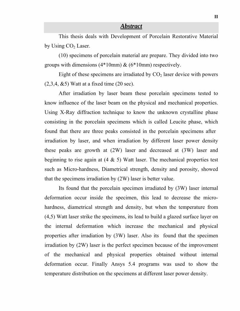
Abstract This thesis deals with Development of Porcelain Restorative Material
by Using CO2 Laser.
(10) specimens of porcelain material are prepare. They divided into two
groups with dimensions (4*10mm) & (6*10mm) respectively.
Eight of these specimens are irradiated by CO2 laser device with powers
(2,3,4, &5) Watt at a fixed time (20 sec).
After irradiation by laser beam these porcelain specimens tested to
know influence of the laser beam on the physical and mechanical properties.
Using X-Ray diffraction technique to know the unknown crystalline phase
consisting in the porcelain specimens which is called Leucite phase, which
found that there are three peaks consisted in the porcelain specimens after
irradiation by laser, and when irradiation by different laser power density
these peaks are growth at (2W) laser and decreased at (3W) laser and
beginning to rise again at (4 & 5) Watt laser. The mechanical properties test
such as Micro-hardness, Diametrical strength, density and porosity, showed
that the specimens irradiation by (2W) laser is better value.
Its found that the porcelain specimen irradiated by (3W) laser internal
deformation occur inside the specimen, this lead to decrease the micro-
hardness, diametrical strength and density, but when the temperature from
(4,5) Watt laser strike the specimens, its lead to build a glazed surface layer on
the internal deformation which increase the mechanical and physical
properties after irradiation by (3W) laser. Also its found that the specimen
irradiation by (2W) laser is the perfect specimen because of the improvement
of the mechanical and physical properties obtained without internal
deformation occur. Finally Ansys 5.4 programs was used to show the
temperature distribution on the specimens at different laser power density.

III
الخلاصة
.حشوات البورسلينعلى خواص (CO2)دراسة تأثير شعاع الليزر يتضمن البحث
و ) ملم 10*4(قسمت إلى مجموعتين بقياس .عينات من مادة البورسلين) 10( تم تحضير
باستخدام جھاز ليزر ثنائي اوكسيد الكربون ثمانية من ھذه العينات شععت. على التوالي) ملم 10*6(
).ثانية 20(وزمن تشعيع ثابت مقداره ) واط 2,3,4,5(بقدرات
لمعرفة تأثير شعاع الليزر على الخواص الفيزيائية العيناتتلك تفحص بالليزربعد التشعيع
لمعرفة الطور المجھول في العينات والذي تبين إن ھذا باستخدام تقنية الحيود السيني .والميكانيكية
. (Leucite)الطور ھو
وعندما , التشعيع بالليزر د ثلاث قمم متكونة في العينات بعدالأشعة السينية وجوأظھرت نتائج
) اطو 3(وقلت عند القدرة ) اطو 2(عند القدرة شععت باستخدام قدرات ليزر مختلفة نمت ھذه القيم
وعندما تم اختبار الصلادة الدقيقة والكسر ). طوا 4,5(ومن ثم بدأت بالصعود مرة أخرى عند القدرات
أحسنخذت أ) طوا 2(إن العينات المشععة بالقدرة شاھدنا ,والمسامية الكثافة المحوري للقوة واختبار
.قيمة
بقيمة تقليلأدى إلى , حصل بھا تشوه داخلي )اطو 3(لاحظ إن العينة المشععة بالقدرة ن
أدت إلى بناء ) طوا 4,5(لكن الحرارة المتولدة من القدرات لكثافةالدقيقة والكسر المحوري واالصلادة
في العينة مما أدى إلى الصعود التشوه الداخليأي تزجيج التشوه الداخليطبقة رقيقة ملأت
.للعينة ةوالفيزيائي ةبالخصائص الميكانيكي
الميكانيكية ھي الأفضل من جانب الخصائص) اطو 2(ذلك وجد إن العينة المشععة بالقدرة ك
.في العينة تشوه داخليوالفيزيائية والتي تم الحصول عليھا من دون حدوث أي
التوزيع الحراري على العينات عند استخدام قدرات لدراسة(Ansys 5.4) برنامج وأخيرا استخدم
.ليزر مختلفة

Appendix (B) (B-7)
Appendices

Appendix (B) (B-7)
Appendix (A)
Appendix (B) (B-7)

Appendix (B) (B-7)
Appendix (B) (B-7)
Appendix (B) (B-7)
Appendix (B)
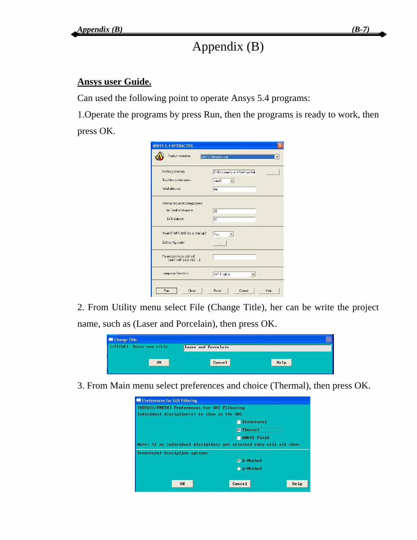
Ansys user Guide.
Can used the following point to operate Ansys 5.4 programs:
1.Operate the programs by press Run, then the programs is ready to work, then
press OK.
2. From Utility menu select File (Change Title), her can be write the project
name, such as (Laser and Porcelain), then press OK.
3. From Main menu select preferences and choice (Thermal), then press OK.

Appendix (B) (B-7) 4. From Main menu select preprocessor and choice (element type, add, solid,
axi-hra 4 node 75), then press OK.
5. From Main menu select preprocessor and choice (material properties,
Isotropic) her we can enter the value of Thermal conductivity, Specific heat,
and Density of specimens, then press OK.
6. From Main menu select preprocessor and choice (modeling, create,
rectangular, by two corners), her can be enter the value of specimens size like
Height and width such as (4*10 and 6*10 mm), then press OK.

Appendix (B) (B-7)
7. From Main menu select preprocessor and choice (mesh tool, mesh, pick
all), then press OK.
8. From Main menu select preprocessor and choice (load, apply, initial
condition, define, pick all), her enter the value of room temperature (300K).
then press OK.

Appendix (B) (B-7)
9. From Main menu select preprocessor and choice (load, Time/Time
frequency, Time-Time stepping) her can be enter the irradiation time (20 sec),
then press OK.
10. From Main menu select preprocessor and choice (load, Apply, Heat flux,
On Line) gives all side of specimens (0) except the top of specimens, then
press OK.

Appendix (B) (B-7)
11. From Main menu select preprocessor and choice (load, Apply, Temperate,
On Node) and select the top side of the specimens and give the difference
temperature effect on the surface like (818.76K, 904.41K, 973.73K,
1028.74K), them press OK.
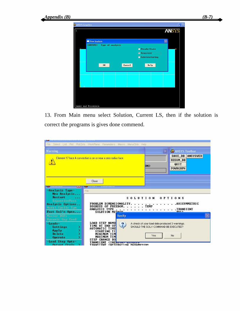
12. From Main menu select preprocessor and choice (load, New Analysis.
Transit) them press OK.
Appendix (B) (B-7)
13. From Main menu select Solution, Current LS, then if the solution is
correct the programs is gives done commend.
Appendix (B) (B-7)
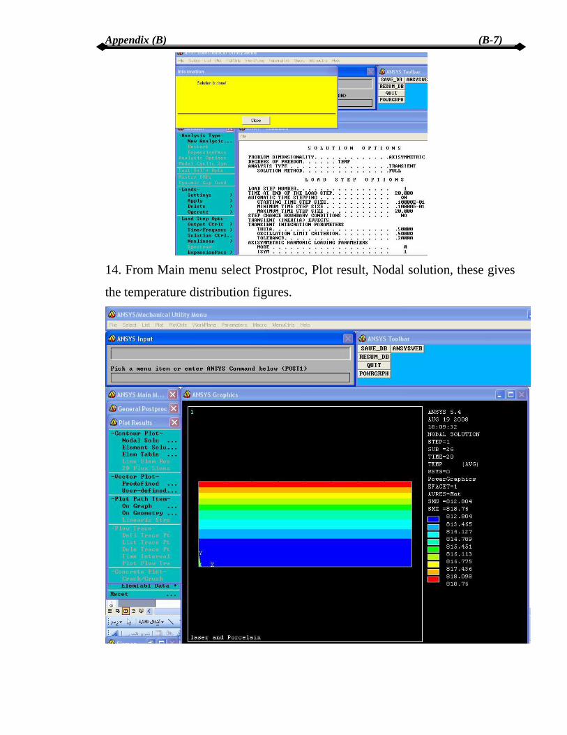
14. From Main menu select Prostproc, Plot result, Nodal solution, these gives
the temperature distribution figures.

Appendix (B) (B-7)
Chapter One Introduction and Historical Review 1
Chapter One Introduction and Historical Review
1.1 Introduction Since its invention in 1960, the laser has found diverse application in
engineering and industry because of its ability to produce high power beams. In the field of metal processing, laser applications include welding, drilling,
cutting, scribing, machining, heat treatment, cladding and alloying. In other
fields, such as medical surgery, laser are also used extensively [1]. Laser are used in a wide rang of applications, from laser surgery to
marking golf clubs, from welding car parts to drilling holes into baby bottle
nipples. The number and type of applications increase daily [2].
In fact, because of their wide applications, are still stories of success
within materials processing and manufacturing. These developments show
that there is still a huge potential for new beam source, which of course set the
demand for additional system technology developments [3].
Porcelain is a specific type of ceramic. It is made up of white clay
(kaolin), quartz, and feldspar. The ingredients are pulverized, blended, shaped
and finally baked. The porcelain has been playing an important role in
restorative dentistry because they allow efficient restorations with great color
stability and resistance [4].
Porcelain has been used in various forms throughout the centuries.
Although it is impossible to know when porcelain was first used successfully,
the Chinese began working with it as early as the 9th century. Around 1700,
France and, somewhat later, England used refined porcelains for the
fabrications of dinner plates and various artistic objects. In dentistry, it was
Alexis Duchateau, a Parisian apothecary, who first used the material for the
fabrication of denture bases in the 18th century.
Chapter One Introduction and Historical Review 2
Today porcelain plays a vital role in restorative dentistry. Common uses
include full coverage as crowns, inlays and onlays, porcelain bridges,
veneering agent, and porcelain-fused-to-metal restorations [5].
1.2 Review of Literature.
1.2.1 Laser in Dentistry The first experiment with laser in dentistry was reported in study about
the effect of a pulse Ruby laser on human caries (Goldman et al, 1964). The
results of that study showed that the effects varied from small (2-mm) deep
holes to complete disappearance of the caries tissue, with some whitening of
surrounding rim of enamel, indicating extensive destruction of caries areas
along with create formation and melting of dentine. Further work in the 1970
focused on the effects of (Nd: YAG) and (CO2) lasers on dental tissues [6].
During the next few years, dental researches studied possible
applications of this visible laser energy. Dr Leon Goldman a dermatologist
had been experimentally with tattoo removal using the Ruby laser focused two
pulses of the red light on a tooth of his dentist brother in 1965. The result was
painless surface crazing of the enamel. The medical community in the mid to
late 1970 had begun to incorporate lasers for soft-tissue procedures, and oral
surgeons added the technology in the early 1980.
Frame, Pecaro, and Pick cited the benefits of CO2 laser treatment of oral
soft-tissue lesions and periodontal procedures, a portable tabletop model was
made available in 1987, and two years later. Since that time, numerous
instruments have been made available for use in dental Patrice, and more are
being developed [7].
The demand for adult orthodontic treatment has been gradually
increasing. Because many adult patients have porcelain crowns or bridges.
Orthodontists are faced with the problem of bonding brackets onto porcelain

Chapter One Introduction and Historical Review 3
surfaces. Optimal bracket adhesion to a porcelain surface required that
orthodontic forces to be applied without bond failure during treatment and the
porcelain integrity not be jeopardized during the debonding procedure.
Porcelain is not appropriate for orthodontic bonding because of the physical
properties of glazed surfaces and the chemical properties of bonding resins.
Various techniques have been suggested for surface treatment of
porcelain before bonding attachments, including deglazing the porcelain by
roughening the surface with a diamond bur or micro-etching with aluminum
oxide particles and then bonding the brackets with or without coupling agent,
and chemical preparation of the previously deglazing porcelain surface by
etching with orthophosphoric acid (OFA) or hydrofluoric acid (HFA) and then
bonding the brackets with or without coupling agent.
However, previous studies have indicated that sandblasting and acid-
etching with OFA produces in sufficient bond strength for clinical
requirements. Bond strength with hydrofluoric acid etching has been shown to
have clinically acceptable values, but the danger of acid burns must be
considered. Lasers have also been used for processing dental materials
especially for fusing the materials on or onto tooth surfaces. In orthodontic,
various types of lasers Nd: YAG, CO2, and Er: YAG have been suggested for
preparing enamel surfaces for bracket adhesion.
Although, some researches found laser irradiation effective for bracket
adhesion on enamel surfaces, others have not found this action due to the bond
strength, more often; lasers are recommended for debonding orthodontic
brackets. Only a few studies have been performed on the laser treatment of
dental porcelain masses. The CO2 laser is well suited for the treatment of
porcelain materials because its emission wavelength is almost totally absorbed
by porcelain [8].

Chapter One Introduction and Historical Review 4
1.3 Aim of Work The aim of this work is to study the influence of CO2 laser on porcelain
restorative material using different laser powers on the mechanical and
physical properties such as micro-hardness, diametrical strength, degree of
crystalline, density and porosity, study the temperature distribution after
irradiation by different laser powers using Ansys 5.4 programs.
Chapter Two Theory Background 5
Chapter Two
Theory Background 2.1 Laser Applications
Laser can deliver very low power to extremely high power, focused
power with a precise spot size/dimension and interaction/pulse time on to any
kind of substrate through any medium.
Laser is distinguished from other electromagnetic radiation mainly in
terms of its coherence, spectral purity and ability to propagate in a straight
line. As a result, laser has wide applications from very mundane (bar code
scanner) to most sophisticated (3-dimensional holography), mere commercial
(audio recording) to purely scientific (spectroscopy), routine (printer) to
futuristic computer), and life saving (surgery) to life threatening
(weapons/guide). Laser is useful in metrology (length/velocity/ roughness
measurement), entertainment (laser light show), medical diagnostics and
surgery/therapy and optical communication/computation.
From printer to pointer, surgery to spectroscopy, isotope separation to
invisible surveillance and medical to material treatment, laser finds a
ubiquitous presence mainly for some unique combination of properties.
These important properties that justify the use of laser in such a wide
spectrum of applications which are:
Spatial and temporal coherence (i.e., phase and amplitude are unique).
Low divergence (parallel to the optical axis).
High continuous or pulsed power density.
Monochromatic.
Chapter Two Theory Background 6
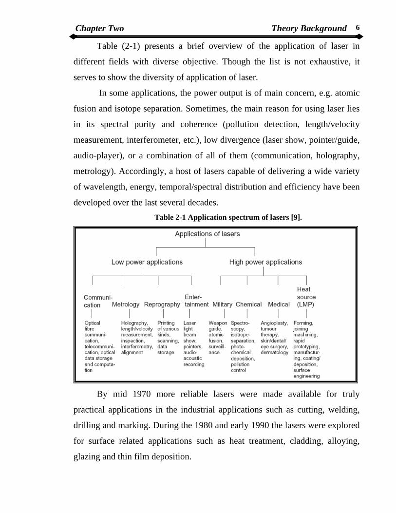
Table (2-1) presents a brief overview of the application of laser in
different fields with diverse objective. Though the list is not exhaustive, it
serves to show the diversity of application of laser.
In some applications, the power output is of main concern, e.g. atomic
fusion and isotope separation. Sometimes, the main reason for using laser lies
in its spectral purity and coherence (pollution detection, length/velocity
measurement, interferometer, etc.), low divergence (laser show, pointer/guide,
audio-player), or a combination of all of them (communication, holography,
metrology). Accordingly, a host of lasers capable of delivering a wide variety
of wavelength, energy, temporal/spectral distribution and efficiency have been
developed over the last several decades. Table 2-1 Application spectrum of lasers [9].
By mid 1970 more reliable lasers were made available for truly
practical applications in the industrial applications such as cutting, welding,
drilling and marking. During the 1980 and early 1990 the lasers were explored
for surface related applications such as heat treatment, cladding, alloying,
glazing and thin film deposition.

Chapter Two Theory Background 7
Table (2-2) summarizes commercially available lasers and their main
areas of application. Depending on the type of laser and wavelength desired,
the laser medium is solid, liquid or gaseous.
Different laser types are commonly named according to the state or the
physical properties of the active medium. Consequently, it have crystal, glass
or semiconductor, solid state lasers, liquid lasers, and gas lasers.
The latter (gas lasers) can be further subdivided into neutral atom lasers,
ion lasers, molecular lasers and Excimer lasers.
The typical commercially available lasers for material processing are
(a) Solid-state crystal or glass laser – Nd:YAG, Ruby.
(b) Semiconductor laser – AlGaAs, and Diode lasers.
(c) Dye or liquid lasers solutions of dyes in water/alcohol and other
solvents.
(d) neutral or atomic gas lasers He:Ne laser, Cu or Au vapor laser.
(e) Ionized gas lasers or ion lasers – argon, and krypton lasers.
(f) Molecular gas lasers – CO2 or CO laser.
(g) Excimer laser XeCl, KrF, etc.
Wavelengths of presently available lasers cover the entire spectral range
from the far-infrared to the soft X-ray [9].

Chapter Two Theory Background 8
Table (2-2) Commercially available lasers and their industrial applications [9].
Laser Year discovery Commercialized Application
Ruby 1960 1963 Metrology, Medical applications,
inorganic material processing
Nd:Glass 1961 1968 Length and velocity measurement
Diode 1962 1965 Semiconductor processing, bio-
medical applications, welding
He:Ne 1962 Light-pointer, length/velocity
measurement, alignment devices
Carbon
Dioxide 1964 1966
Material processing- cutting/ joining,
atomic fusion
Nd:YAG 1964 1966 Material processing, joining
Argon ion 1964 1966 Powerful light, medical applications
Dye 1966 1969 Pollution detection, isotope
separation
Copper 1966 1989 isotope separation
Excimer 1975 1976 Medical application, material
processing, coloring
The advantages of lasers in industrial applications include:
Lasers do not suffer tool wear. They can cut extremely hard materials,
such as super alloy, diamond, ceramic, etc without being eroded.
Laser can be focused to very small areas, producing high energy
densities exactly where it is needed, without affecting the neighboring
areas of the work piece.
Laser radiation is clean. It does not introduce impurities into the work
piece, it can work in vacuum or in an inert gas environment during the
procedure.

Chapter Two Theory Background 9
Lasers can be easily (taught) to process two-dimensional or even three-
dimensional parts. That is lasers are fully compatible with computer-
controlled manufacturing.
When used for cutting, lasers can produce clean and sharp edges that
require little or no additional processing.
When used for drilling, lasers can produce small diameter and deep
holes that are otherwise unattainable by conventional tools.
Lasers are compatible with micromachining and nanofabrication, such
as cutting micro-gears, tiny ball bearing, etc up to hard difficult
materials [2 ] .
2.2 Laser Matter interaction When the electromagnetic radiation strikes a surface the wave travels as
shown in Figure (2-1).
Figure (2-1) The phase and amplitude of an electromagnetic ray striking an air/solid
interact and undergoing reflection and transmission[10].
Some radiation is reflected, absorbed, and transmitted. As it passes
through the new medium it will be absorbed according to Beer Lambert law : ZeII β−= 0 ……………….. ……………………………………. (2-1).
The absorption coefficient β, depend on the medium, wavelength of the
radiation and the intensity [10].

Chapter Two Theory Background 10
2.3 Laser Material Processing The increasing demand of laser in material processing can be attributed
to several unique advantages of laser namely, high productivity, automation
worthiness, non-contact processing, elimination of finishing operation,
reduced processing cost, improve product quality, greater material utilization
and minimum heat affected zone. Table (2-3) shows a general classification of
laser material processing techniques. Table (2-3) Classification of laser material processing [9].
In general, application of laser to material processing can be grouped
into two major classes, (a) Applications requiring limited energy/power and
causing no significant change of phase or state. (b) Applications requiring
substantial amount of energy to induce the phase transformations.

Chapter Two Theory Background 11
The first category includes semiconductor annealing and etching,
polymer curing, scribing/marking of integrated circuit substrates, etc.
The second type of application encompasses cutting, welding, fusion,
heat treatment, etc.
The average power and efficiency of lasers are not important for the
former category that involves no change in phase or state. Lasers suitable for
this group of applications include, but not limited to, Excimer lasers (KrF,
ArF), ion lasers (Ar+, Kr+), metallic vapor lasers (cadmium, selenium, copper,
gold), semiconductor lasers (gallium aluminum arsenide, etc), and molecular
lasers (CO2, CO, etc).
For the second category, laser power, efficiency and interaction time are
crucial as the processes involved single or multiple phase changes within a
very short time. Because of high energy requirement, for this class of
operations, CO2 and Nd: YAG lasers are practically the only choice [9] .
2.4 Carbon Dioxide Laser The carbon dioxide (CO2) laser is a molecular laser in which molecular
vibrations rather than electronic transitions provide the mechanism for lasing
action [11].
At an infrared wavelength around 10.6 µm, the beam is readily
absorbed by most materials and readily converted into heat. Power outputs
ranging from big (compared to most common lasers, such as He:Ne) to
enormous, with power outputs in excess of 50 kW possible. Even the smallest
lasers output with several watts, enough to burn many materials on contact
with the beam. Aside from high power outputs, the other distinguishes feature
is high efficiency, with typical efficiencies of industrial lasers being over 10%.
These features combine to mark the CO2 laser the defect to standard materials
processing laser, with application including cutting and welding of such
materials as hardened metals and ceramic.

Chapter Two Theory Background 12
There are a variety forms of CO2 lasers, based on tube design. Many
small lasers resemble any other gas laser. Being a glass tube with two cavity
optics, while larger lasers may resemble an Excimer structure, with long,
transverse electrodes [12].
2.4.1 Lasing Medium CO2 lasers use a mixture of carbon dioxide, nitrogen, and helium in the
approximate ratio 1:2:8, with each gas in the mixture assuming a specific role
in this laser. The quantum system of CO2 laser uses a scheme similar to that of
the He:Ne lasers, in which the pump level for this four-level system is in a
separate species from the lasing atom. Nitrogen (N2) becomes excited with
energy from the discharge and the first vibrational energy level of that
molecular provides a pump energy level that matches very closely the upper
laser level (ULL) in the CO2 molecular (the first asymmetric stretch mode,
001). This is identical to the role of helium in the He:Ne laser. A large
quantity of nitrogen (i.e., a higher percentage that CO2) ensures that CO2
molecules in the ground state are pumped rapidly to the ULL.
Lasing occurs as result of transition between two vibrational energy
levels in the carbon dioxide molecule, the levels resulting from the various
modes of vibrations possible. Transition can terminate at possible lower
levels, as shown in Figure (2-2), with the most common (and powerful)
transitions resulting in the production of radiation at 10.6µm.

Chapter Two Theory Background 13
Figure (2-2) Energy levels in the carbon dioxide laser [12].
From that level, depopulation take place in a two-step process by with
either lower laser level (LLL) decays to a lower energy state, corresponding to
the bending motion of the molecule (010) and finally, to ground state. The
addition of helium to the gas mixture ensures that CO2 molecules at the LLL
are depopulated quickly required for a sizable population inversion.
Helium also serves to conduct heat from the discharge to the walls of
the tube since helium conducts heat much better than most gases do. This
provides a means of decreasing the thermal population of energy levels of the
CO2 molecule (which lie quit close to ground state), again helping to ensure
that an inversion occurs. As well as (purely) vibration levels, rotational of the
CO2 molecule are responsible for the output of spectrum of this laser, since
rotational levels serve to split each major vibration level into a cluster of
multiple closely spaced levels. As a result, the actual laser output is a series of
closely spaced wavelengths covering the range 9.2 µm. to almost 11µm,
centered around 9.6µm and 10.6 µm. The 10.6 µm transition is a normal CW
laser, for example, consists of over 20 transitions in the wavelength range
10.44 to 11.02 µm. with a diffraction grating added to the cavity for tunability,
the range of outputs makes the laser useful as a source for IR spectroscopy,

Chapter Two Theory Background 14
water cooling is required for most CO2 lasers not just to remove discharge heat
but also to reduce the thermal population of the lower energy levels, which are
very close to ground level. The output power of most CO2 laser is quit
sensitive to plasma temperature, and a blocked or restricted cooling water line
can easily result in a decrease in output power. To reduce this effect, the laser
system should shutdown when the temperature reach 40 to 50 oC, while the
plasma tube would probably tolerate much higher temperature, laser output
would drop drastically at these temperature. There are two type of CO2 laser
tube (longitudinal and transverse) [12].
2-5 Dental Materials Ceramic defined as a class of inorganic nonmetallic solids that are
subjected to high temperature in manufacture and/or use. A ceramic is
therefore an earthy material usually of a silicate nature and may be defined as
a combination of one or more metals with non-metallic element, usually
oxygen. The atomic bonds in ceramic crystals have both covalent and ionic
characters. These strong bonds are responsible for the great stability of
ceramics and important very useful properties, such as hardens, high modulus
of elasticity and resistance to heat and chemical attacks. On the other hands,
the nature of this bonding creates difficulties for the dental ceramist since all-
ceramic materials are brittle. Ceramics were probably the first materials to be
artificially made by humans and porcelain was a many the first materials to be
the subject of early laboratory research by scientists.
Three basic types of ceramic materials were developed: Earthenware is
fired at low temperature and is relatively porous. Stoneware which appeared in
china in about 100 years BC is fired at a higher temperature than earthenware
which results in both higher strength and also renders the material impervious
to water. The third material is porcelain, which was obtained by fusing white
china clay with china stone to produce white translucent stoneware.

Chapter Two Theory Background 15
Many attempts at imitating Chinese porcelain were made in Europe in
seven teeth century. Attempts were also made to dispense white clay particles
in glass in the sixteenth century, however these attempts were not able to
simulate the Chinese porcelain.. The introduction into dentistry of the art of
fusing porcelain must be stated as one of the most important and significant
historical developments in dental material science. De cheman’s, all porcelain
dentures were far from the complete answer to full denture fabrications. By
the early 1800, complete porcelain denture has been a abandoned. However,
these all porcelain dentures did stimulate work on the manufacture of
individual porcelain teeth for attaching to a plate of ivory or metal, and were
quite different for earthenware, stoneware and domestic porcelain, as
indicated in Figure (2-3).
Figure (2-3) Relative composition of ceramic products based on feldspar, kaolin and
quartz [23].
Elia Wildman in 1838 was able to formulate much more translucent
porcelain with shades much closer to nature teeth. The commercial
manufacture of porcelain teeth is understood to have commenced in France in
early 1800. The industry was later introduced into America in 1817. Porcelain
teeth were not manufactured in England until 1870.

Chapter Two Theory Background 16
Amber Tess improved the design of the dental coke burning porcelain
ovens in 1880, using gas , oil and finally the electric furnace was introduced at
the end of the century. Fauchard, (French dentist) is considered the father of
modern dentistry and authors at the second half of the eighteenth century
attempted to use porcelain for dental applications. Their efforts working in the
demanding and potentially destructive intraoral environment were largely
unsuccessful. Ceramic materials are being increasingly as dental biomaterials
in the form of the veneers, crowns, inlays and bridges. The appeal of ceramics
as structure dental materials is based on their esthetics, low density, high
hardness, chemical inertness, and wears resistance. A major goal of ceramics
research and development is to produce stronger, tougher ceramics that are
structurally reliable in dental applications [13].
2.6 Composition of Dental Porcelain The composition of the various types of porcelain is summarized in
table (2-4). Table 2-4 Composite of various types of porcelain [13].
Material Clay (kaolin) silica feldspar Glass
Decorative
porcelain 50 25 25 0
High-fusing
(dental) 5 15 80 0
Low-fusing
(dental) 0 25 60 15

Chapter Two Theory Background 17
It can be seen that there are considerable difference in composite
between the dental porcelains and decorative porcelain. Indeed the dental
porcelains contain little or more clay and possible would be more aptly
described as a dental glass. Conventional dental porcelain is a vitreous
ceramic based on silica (SiO2) network and potash feldspar (K2O. Al2O3.
SiO2) or soda feldspar (Na2O. AlO2. SiO2) or both, pigments opacifiers, and
glasses are added to control the fusion temperature, sintering temperature,
thermal contraction coefficient and solubility. The feldspar used for dental
porcelains are relatively pure and colorless. Thus pigments must be added to
produce the hues of nature teeth on the color appearance of the tooth colored
restorative materials that may exist in adjacent teeth.
Dental porcelain is produced from a blend of quartz (SiO2), feldspar
(potassium aluminum silicate), sodium aluminum silicate, and other oxides.
The typical composition is given in table (2-5). Table( 2-5) Composition of high, medium and low fusing porcelain [13].
Composition High-fusing Medium-fusing Low-fusing
SiO2 72.9 63.1 66.5
Al2O3 15.9 19.8 13.5
Na2O 1.68 2.0 4.2
K2O 9.8 7.9 7.1
B2O3 - 6.8 6.0
ZnO - 0.25 -
ZrO2 - - -

Chapter Two Theory Background 18
Although, the actual composition will very depending on the proposed
use of the end products. Dental porcelain is usually received from the
manufacture in powder form, which is mixed with either water or water based
glycerin containing liquid to form a past of workable consistency. The modern
dental materials are in fact basically a borosilicate feldspathic glass. Thus
improved translucency was mainly achieved by the lowering of the kaolinites
content or its complete removal from the composition. This resulted in the
composition moving away from the mullets zone and into the lenzite zone.
“Kerls handbook” of 1907 gives the following mineral composition for
the early dental porcelain developed by Stockton table (2-6). Table (2-6) Mineral composition for the early dental porcelain [13].
Composition Percentage
Feldspar 78.0
Kaolinite 15.3
Potash silicate 4.7
Dehydrated borax 2.9
The average dental porcelain will therefore contain a minimum content
of about 60 percent SiO2. Typical low fusing dental porcelain should rarely be
referred to as dental glass and would have a composition as in table (2-7). Table (2-7) Typically low fusing dental porcelain composition [13].
Composition Weight percent
SiO2 69.36
B2O3 7.53
CaO 1.85
K2O 8.33
Na2O 4.81
Al2O3 8.11

Chapter Two Theory Background 19
Such as a fluxed glass would have a maturing temperature of 900oC to
930oC.Conventional feldspathic porcelain is composed premature of SiO2
64%, Al2O3 18% with various amount of K2O and Na2O 8-10 % to control
expansion [13].
2.6.1 Silica
Pure quartz crystals (SiO2) are used in dental porcelain, and are ground
to the grain size possible, silica remains unchangeable at the temperature
normally used in firing porcelain, and this contributes stability to the mass
during heating by providing a framework for other ingredients.
The stability of the glass is highly dependent on the silicon-oxygen
lattice and the covalent bonds must not be reduced too much, otherwise,
diversification may arise. The average dental porcelain will therefore contain a
minimum content of the a bout 60% SiO2 [14].
2.6.2 Feldspar
Nature feldspars are mixtures of albeit Na2Al3Si6O16, and orthoclase
K2Al7Si6O16 with free crystalline quartz. These feldspars are never pure and
the ratio of soda (Na2O) to potash (K2O) may very quit considerably. For
dental purposes, high potash content feldspar is generally selected because of
its increased resistance to pyroplastic flow. Feldspar contains oxides of both
potassium and sodium, these break down the Si-O network and thus are
known as glass modifies.
Two desirable consequences result:
1. The softening temperature of the glass is reduced.
2. The coefficient of thermal expansion is increased the manufacture
adjusts the oxide content so that coefficient of thermal expansion of
dental porcelain will be close to the corresponding value for the
alloys used to make the substructure. Extensive breakdown of the
Chapter Two Theory Background 20
Si-O network may occur, and diversifications results from
crystallization of the glass.
This occurs of porcelain is fired too often, and it is typically associated
with loss of physical properties and appearance [13].
2.6.3 Kaolin
Kaolin is produced in nature by the weathering of feldspar, during
which the soluble potassium silicate is washed out by acid waters. The residue
is deposited in the form of clay. Only the purest clay or kaolin are used in
porcelain [15].
Kaolin gives porcelain its properties of opaqueness and which mixed
with water, it becomes sticky and acids in forming a workable mass of the
porcelain during molding [14].
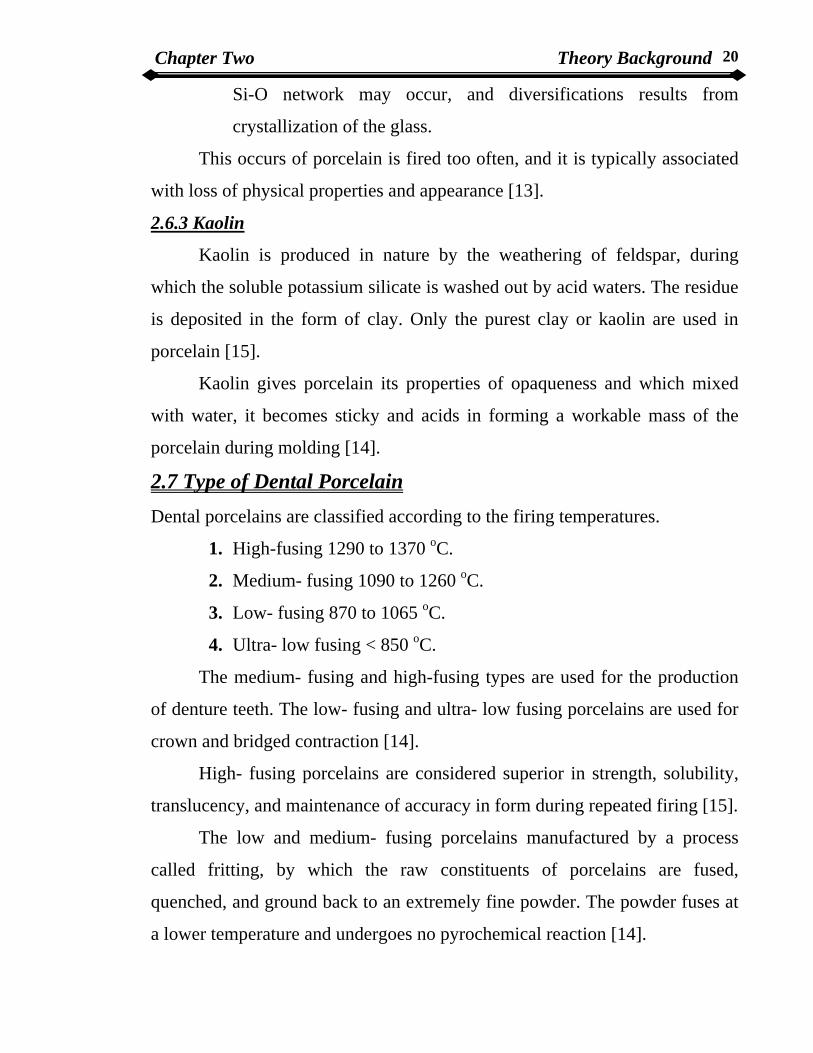
2.7 Type of Dental Porcelain Dental porcelains are classified according to the firing temperatures.
1. High-fusing 1290 to 1370 oC.
2. Medium- fusing 1090 to 1260 oC.
3. Low- fusing 870 to 1065 oC.
4. Ultra- low fusing < 850 oC.
The medium- fusing and high-fusing types are used for the production
of denture teeth. The low- fusing and ultra- low fusing porcelains are used for
crown and bridged contraction [14].
High- fusing porcelains are considered superior in strength, solubility,
translucency, and maintenance of accuracy in form during repeated firing [15].
The low and medium- fusing porcelains manufactured by a process
called fritting, by which the raw constituents of porcelains are fused,
quenched, and ground back to an extremely fine powder. The powder fuses at
a lower temperature and undergoes no pyrochemical reaction [14].

Chapter Two Theory Background 21
Low firing temperatures are a definite assistance in the fusion of
porcelain to metal, since the differences in the coefficients of expansion of the
porcelain and metal can be tolerated better at lower temperature ranges [15].
Resent tests of low- fusing products indicate that they are essentially as
strong as the high- fusing types, and their solubility and translucency are
adequate. Some of the ultra-low- fusing porcelains are used for titanium and
titanium alloys because of their low-expansion coefficient that closely match
those of the metals and because the low firing temperature reduces of sag
formation in fixed partial denture frameworks.
Leinfelder in 2000 reported that low-fusing porcelain was developed to
offset the major disadvantages of traditional dental porcelains representing a
major change in direction, one of the basic differences between this
formulation and those that have been used for long periods of time is a
significant type (fincese) versus around 940oC for conventional type. He
mentioned that this 200oC differential has imparted a number of positive
characteristics to the final restorative.
Finesse low-fusing dental porcelain exhibited slightly lower wear
resistance than other porcelains. This could be clinical advantage as its wear
property comes closer to that of enamel [14].
Chapter Three Experimental Parts 22
Chapter three
Experimental parts 3.1 Introduction
This chapter deals with the measurement of a physical properties and
mechanical properties of the prepared specimens experimentally. It includes
specimens preparation methods, irradiation by CO2 laser, crystalline phase
deformation by using X-Ray diffraction technique, degree of crystalline
measurement, the mechanical properties measurement (density and porosity
measurement, micro-hardness, diametrical strength,). Also it would study the
temperature distribution on the surface and inside the specimens of different
laser power density by using Ansys 5.4 programs.
3.2 Specimens preparation method In this project (10) specimens of porcelain were prepare, which are
consists from the following components from Vita company as shown in table
(3-1). Table (3-1) Composition of dental porcelain.
Material Weight percent %
Silica 63
Alumina 17
Boroc oxide 7
Potash (K2O) 7
Soda (Na2O) 4
Other oxide 2

Chapter Three Experimental Parts 23
The porcelain powder was mixed with water to form a paste, this paste
divided into (10) specimens, each specimen put by using a syringe (5cc) to
form the final shape which is require.
Figure (3-1) The die
These (10) specimens have a cylindrical shape. These specimens are
moist and have a different dimension, so the dimension of these specimens
must be standardized by using another process to get the required. This
achieved by heating the specimens in a special programmable furnace type
IVOCLAR program X1 as shown in Figure (3-2).
Figure (3-2) The furnace
Putting all the specimens carefully in the furnace and turn ON adjusting
the temperature of the furnace on (600 oC) for a period time (15 min). Turned
OFF the furnace and let the specimens in the furnace to reach the room
temperature gradually.

Chapter Three Experimental Parts 24
This process was done to avoid instantiation any crack in the porcelain
specimens and to get a clear and clean surface and standard of all prepared
specimens.
To get a smooth and unique shape a polishing process would done by
using electrical diamond saw. The final shapes of the prepared specimens
which are needed in the project are (4*10 & 6*10 mm).
3.3 Specimens Irradiation by CO2 Laser
The prepared specimens irradiated by transverse sealed CO2 laser with
output (16W), the laser device which is used in this work is shown in Figure
(3-3), type DJG107-1518, input AC 220V, output V: 16kV/120 mA, it has
efficiency 10%.
Figure (3-3) CO2 laser system
Two group of the specimens irradiated by laser. Four specimens having
a dimension of (4*10mm). And four specimens having a dimension
(6*10mm).
Figure (3-4) shows the experimental setting for irradiation by CO2 laser.

Chapter Three Experimental Parts 25
Figure (3-4) Experimental setting for CO2 laser
The laser system produce output mentioned above (16W), but in present
work (2-5W) output power would be needed, so the laser system was
calibrated between input current to the laser tube and output power by using
(CO2) power meter device type SJG-100W as shown in Figure (3-5).
Figure (3-5) CO2 Power meter device
Table (3-2) show this calibration.

Chapter Three Experimental Parts 26
Table (3-2) Current/power calibration.
Current (mA) Power (W)
1.8 1
2 1.5
2.4 2
2.8 2.5
3 3
3.2 3.5
3.4 4
3.8 4.5
4 5
4.2 5.5
4.6 6
5 6.5
5.2 7
5.4 7.5
5.8 8
6 8.5
6.2 9
6.4 9.5
6.8 10
To get a perfect irradiation the specimens are put at the distance (5cm)
from the laser tube aperture. The laser tube aperture has (10mm) spot size
diameter. This spot cover the entire specimens surface.
Also to achieve a precise alignment between the porcelain specimens
and laser tube aperture.
Chapter Three Experimental Parts 27
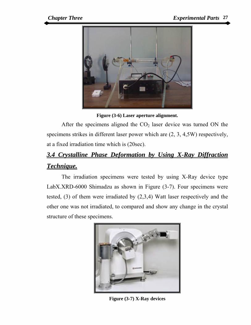
Figure (3-6) Laser aperture alignment.
After the specimens aligned the CO2 laser device was turned ON the
specimens strikes in different laser power which are (2, 3, 4,5W) respectively,
at a fixed irradiation time which is (20sec).
3.4 Crystalline Phase Deformation by Using X-Ray Diffraction
Technique. The irradiation specimens were tested by using X-Ray device type
LabX.XRD-6000 Shimadzu as shown in Figure (3-7). Four specimens were
tested, (3) of them were irradiated by (2,3,4) Watt laser respectively and the
other one was not irradiated, to compared and show any change in the crystal
structure of these specimens.
Figure (3-7) X-Ray devices

Chapter Three Experimental Parts 28
3.4.1 Determination of Crystal Phase Method. In order to Bragg law the diffraction angle which limited the crystal
phase must be measured by using different parameter such as the intensity,
angle of diffraction, and d-spacing.
The angle range is (2θ) from (20-60) degree for all specimens. To get this
range using X-Ray technique for quantitative and qualitative analysis for
unknown crystalline component, then the diffraction mode considered as
idiosyncrasy of material property which limited by.
1. Using (2θ) value for all peaks which appear at diffraction.
2. Calculate the d-spacing for diffraction angle.
Listing each value for d-spacing value and relative intensity for diffraction
line, then considering the maximum value appear in each run as (100%)
intensity.
3. Compare all d-spacing value with higher intensity to know the
crystalline phase by using ASTM files to show the unknown phase is
appeared.
3.5 Degree of Crystalline Procedure To calculate the degree of crystalline, there are many methods that’s
depends on the changing in the physical properties of the matter by
appearance of crystalline of the matter.
The most important method and most available is the X-Ray diffraction
in which the spectrum or mode consist from peaks that produce from the
coherence scattering of the rays from the crystalline level of the specimens.
Assume that the intensity of the X-Ray scattering on radiated porcelain equal
to (Ip ) and (Ix) equal to the intensity of the scattering ray produce from the
non-radiated mode of porcelain, the following relation use to calculate the
percentage of crystalline of the porcelain specimens.

Chapter Three Experimental Parts 29
Degree of crystalline of irradiate porcelain from equation [16].
Degree of crystalline %100% ×−
=p
Xp
III
……………………………... (3-1)
3.6 Mechanical Properties Measurements
3.6.1 Micro-Hardness Procedure Hardness not considered as a physical property but as a complex
function of a group of a physical properties shared in different degrees
depends on the testing way and the environment in which the test done.
The basic principle of hardness not understand till now, the general idea
of hardness as a property of metals referred to rigidity and surface constancy
and its resistance to the external factors. In this work the Vickers method was
used which is called (indentation hardness). In Vickers method the top of the
diamond pyramid (that used to produce the indentation) strike the surface of
the porcelain specimens, this will leave identity on the place that strike, in
which its area represent the basic measure of hardness.
The terms hardness according to Vickers method as the exposed load by
(Kg) on the area of contact between diamond pyramid and the surface of the
specimens in (mm2).
Hardness is a key parameter in the choice of ceramic for abrasives, tool
bits, bearings, wear resistant applications, and resistance to particulate erosion
and ballistic impact.
The hardness of a material is related to the material characteristics
which give stiffness and strength. Hardness is an important characteristic of a
material, as it contributes to resistance to erosion/wear processes. At high
temperature, however, engineering alloys become "Softer" and so ceramics
are often used to give wear resistance.

Chapter Three Experimental Parts 30
The hardness of a material may be specified in terms of some standard
test involving indenting or scratching of the surface of the material, the harder
a material the more difficult it is to make an indentation or scratch.
Five specimens of dimension (4*10mm) were tested for micro-hardness
procedure. The specimens were tested in digital micro hardness tester HVS-
1000 by harden fixed time at 10 sec as shown in Figure (3-8).
Figure (3-8) Digital Micro-hardness device
Using Vickers method to calculate micro-hardness, considering one
specimen which not irradiated by CO2 laser beam and four specimens
irradiated by CO2 laser beam. These specimens were put in the micro-
hardness device to know the hardness value of each specimen.
3.6.2 Diametrical Strength Procedure. The Five specimens from the previous process were tested for the
diametrical strength. And this measurement will help to compare between the
micro-hardness and diametrical strength test. This test was done by using
Brazilian test device as shown in Figure (3-9).
Chapter Three Experimental Parts 31
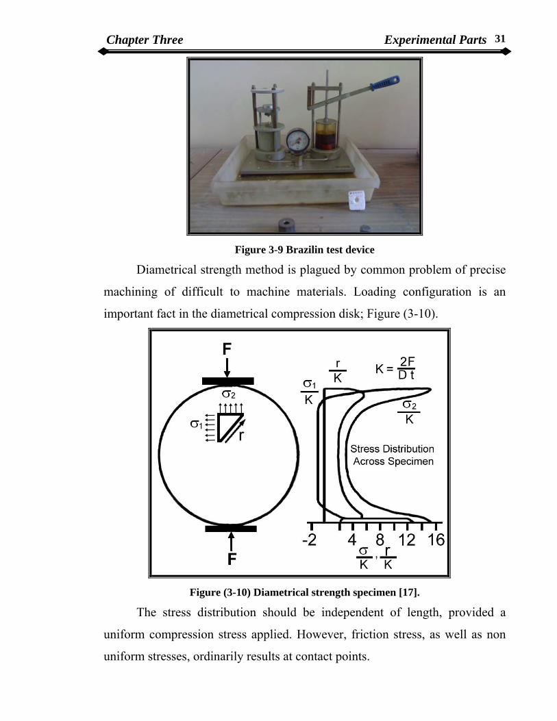
Figure 3-9 Brazilin test device
Diametrical strength method is plagued by common problem of precise
machining of difficult to machine materials. Loading configuration is an
important fact in the diametrical compression disk; Figure (3-10).
Figure (3-10) Diametrical strength specimen [17].
The stress distribution should be independent of length, provided a
uniform compression stress applied. However, friction stress, as well as non
uniform stresses, ordinarily results at contact points.

Chapter Three Experimental Parts 32
The simple theory describing the stress distribution under a uniform diametric
load on a disk-shaped specimen predicts a uniform tension field at the center
of the disk [17]:
(Diametrical strength) DtF
D πσ 2
= ………………………………….……..(3-2).
where F is the applied load (N), D is the disk diameter and t is the thickness of
disk.
The stress field in the transverse direction is highly dependent on the
width of load application and becomes highly compressive the disk test has
therefore been used to attempt to study biaxial stress failure response.
3.7 Density and Porosity Five specimens of dimension (6*10) mm (four of them irradiated by
CO2 laser and the fifth one is not irradiated by CO2 laser ) were performed
density and porosity test.
Bulk density and open porosity are determined by using Archimedes
Method using distilled H2O. The mass of material in air is divided by its
buoyancy (reduction in weight) when suspended in a liquid medium to give a
measurement of density.
The density of a material is:
Density = Mass/ Volume ………………………….…………………….(3-3).
There are three volume expressions in common use:
1. Apparent volume or bulk volume: includes the volume of the solid
component, open pores and sealed pores, determined by the
difference between the soaked weight (S) and the immerse weight
(I) of the soaked piece.
2. True volume: The volume of the solid component only, is determined
by crushing the piece into powder form so that all the pores are
destroyed and using "Density Bottle" method.

Chapter Three Experimental Parts 33
3. Apparent solid-volume: The volume of the solid component and
sealed pores only, is obtained from the difference between the dry
weight (D) and the immersed weight (I) of the piece.
The densities and porosity expression are:
Apparent or bulk density (ρb) = mass/apparent volume
= D/S-I ………….……………….......… (3-4).
True density (ρt)= mass/true volume
Apparent-solid (sintered) density= mass/apparent-solid volume
= D/D-I …………………...……….…. (3-5).
Percentage apparent porosity= open pore volume/total volume *100%
A.P% = S-D/S-I *100 …………………………….(3-6).
Total (true) porosity %= 1- ρb/ρt *100 ………………………………….. (3-7).
3.8 Ansys Programs This programs study the different laser power density are used in the
previous testing which converted to the temperature value, and show the
temperature distribution inside and on the surface of specimens. Ansys 5.4
programs was used to show the temperature distribution irradiated by different
power (2, 3, 4, and 5) Watt of the CO2 laser device.
Chapter Four Results and Discussion 34
Chapter four
Results and Discussion 4.1 Introduction
This chapter presents both the calculation performed and the results
obtained. It also presents a discussion of all results obtained in the present
works. This project would concerned on the heat treatment of porcelain by
using CO2 laser at a fixed time and study the change in physical and
mechanical properties due to heat treatment.
This chapter divided into following;
1. Crystallographic Analysis.
2. Mechanical properties.
3. Density and Porosity calculation.
4. Temperature distribution using Ansys 5.4 programs.
4.2 Crystallographic Analysis
From X-Ray diffraction used the crystallographic analysis on tested
specimens which were irradiated by CO2 laser beam on a fixed time for all the
specimens (20 sec), a crystalline phase appear which is a dominate in all the
specimens and this phase called Leucite (KAlSi2O6).
Leucite- potassium alumina- silicate (KAlSi2O6) is the major crystalline phase
in most high-expansion dental porcelains.
Leucite crystalline was naturally occurring in the cubic form. On
cooling there is a phase transition to a tetragonal form.[18]
For dental porcelains this transformation occur between 700-
1300K.[19]
Leucite based ceramic materials are a subject of an extensive scientific interest
in recent year, especially in the field of dental prosthesis.[20]
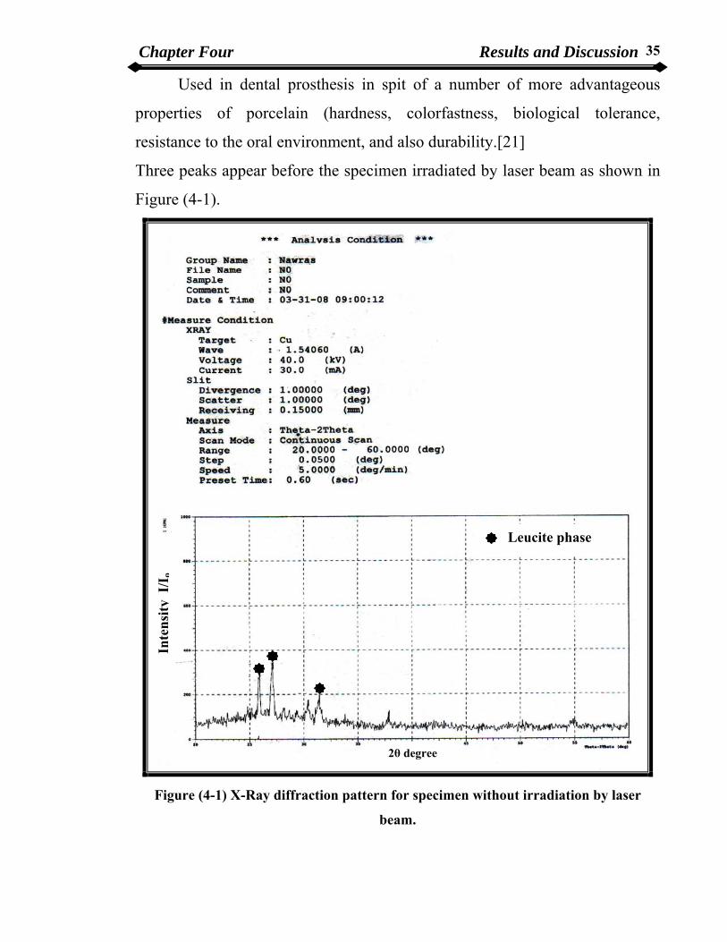
Chapter Four Results and Discussion 35
Used in dental prosthesis in spit of a number of more advantageous
properties of porcelain (hardness, colorfastness, biological tolerance,
resistance to the oral environment, and also durability.[21]
Three peaks appear before the specimen irradiated by laser beam as shown in
Figure (4-1).
Leucite phase
Inte
nsity
I/I
o
2θ degree
Figure (4-1) X-Ray diffraction pattern for specimen without irradiation by laser
beam.
Chapter Four Results and Discussion 36
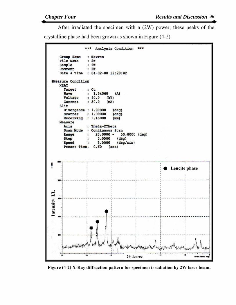
After irradiated the specimen with a (2W) power; these peaks of the
crystalline phase had been grown as shown in Figure (4-2).
Leucite phase
Inte
nsity
I/I
o
2θ degree
Figure (4-2) X-Ray diffraction pattern for specimen irradiation by 2W laser beam.

Chapter Four Results and Discussion 37
It’s found that the heat produced from (2W) laser when irradiated the
specimen was the best heat to relax and re-arrangement of the molecules and
atoms of the specimen, so the crystalline phase begin to grow. This heat not
causes re-conversion of the phase.
In (3W) laser these peaks decrease in intensity, because of internal
deformation occurred in the specimen which leads to decrease of the
mechanical properties of the specimens as shown in Figure (4-3).
Leucite phase
Inte
nsity
I/I
o
2θ degree
Figure (4-3) X-Ray diffraction pattern for specimen irradiation by 3W laser beam.
Chapter Four Results and Discussion 38
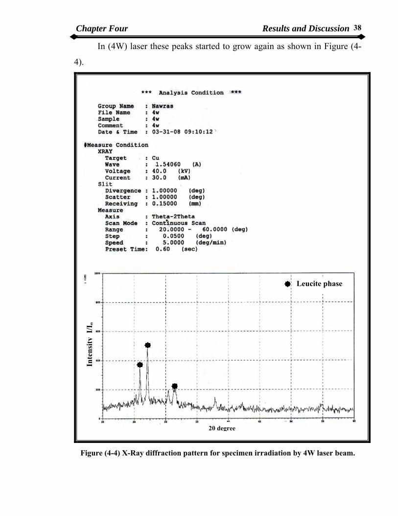
In (4W) laser these peaks started to grow again as shown in Figure (4-
4).
Leucite phase
Inte
nsity
I/I
o
2θ degree
Figure (4-4) X-Ray diffraction pattern for specimen irradiation by 4W laser beam.
Chapter Four Results and Discussion 39
This grow occur due to glazed on the internal deformation that appear
in (3W) power laser. These results obtained by using comparison between the
value of the diffraction angle and the intensity produced from the X-Ray
diffraction patterns.
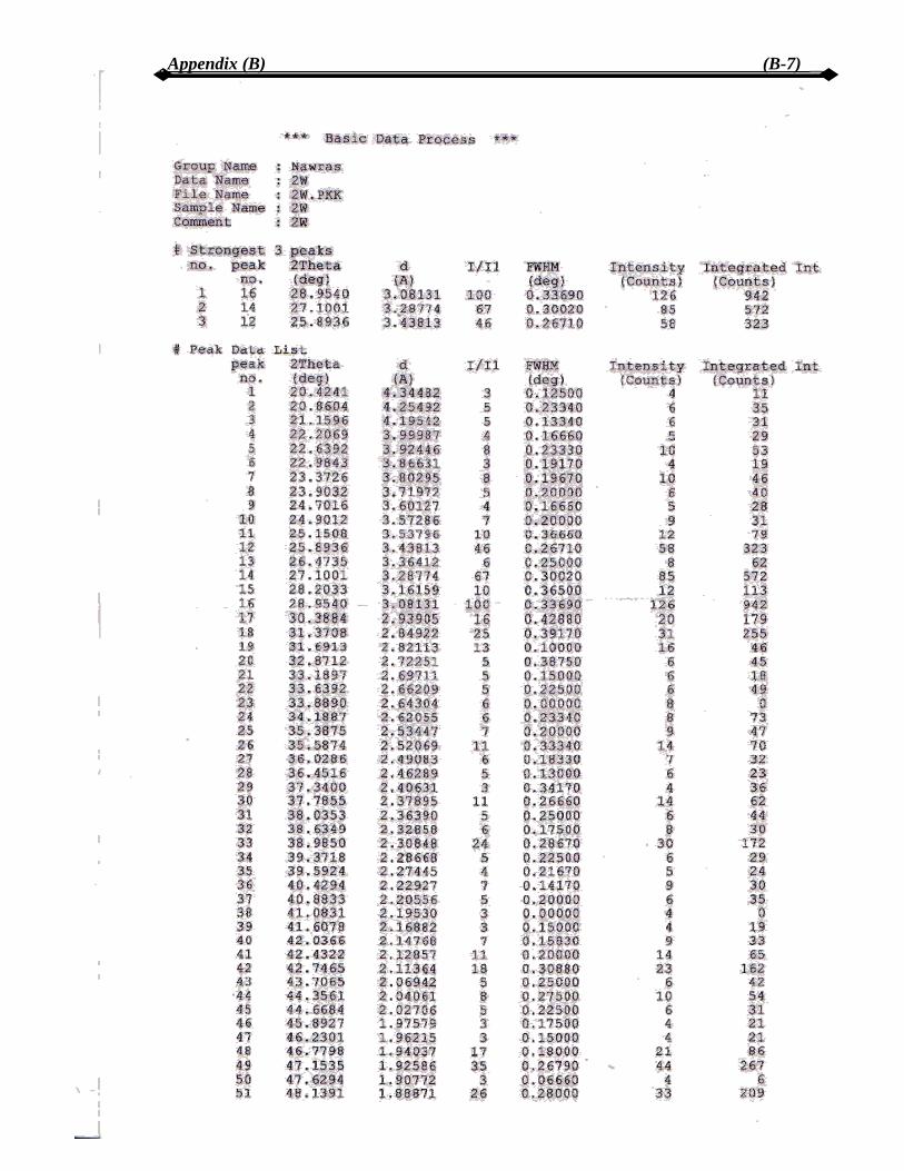
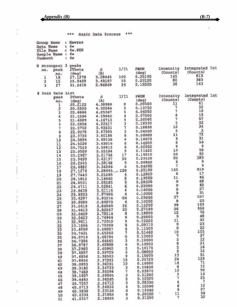
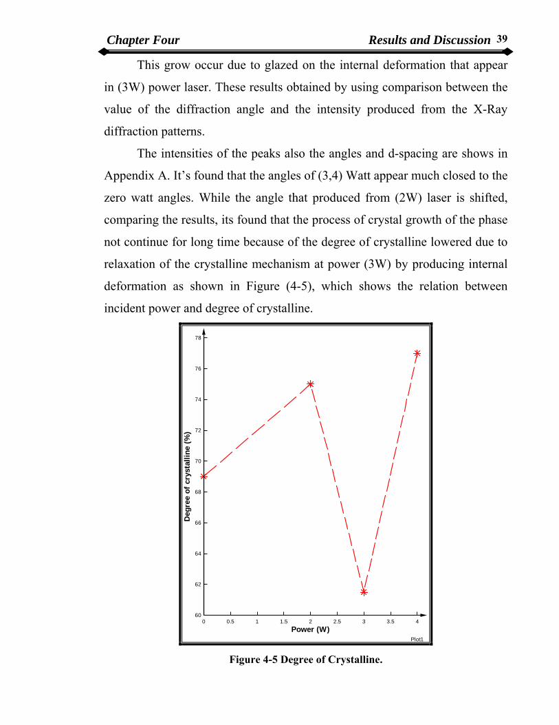
The intensities of the peaks also the angles and d-spacing are shows in
Appendix A. It’s found that the angles of (3,4) Watt appear much closed to the
zero watt angles. While the angle that produced from (2W) laser is shifted,
comparing the results, its found that the process of crystal growth of the phase
not continue for long time because of the degree of crystalline lowered due to
relaxation of the crystalline mechanism at power (3W) by producing internal
deformation as shown in Figure (4-5), which shows the relation between
incident power and degree of crystalline.
Plot1
Power (W)
Deg
ree
of c
ryst
allin
e (%
)
0 0.5 1 1.5 2 2.5 3 3.5 460
62
64
66
68
70
72
74
76
78
Figure 4-5 Degree of Crystalline.

Chapter Four Results and Discussion 40
The degree of crystalline was calculated from equation (3-1), and listed
in table (4-1). Table 4-1 power and degree of crystalline.
Power (W) Degree of crystalline (%)
0 69
2 75
3 61.5
4 77
The result of the degree of crystalline shows that the higher degree of
crystalline at (4W) laser power and it’s equal to (77%).
Comparison present result with the previous researches (8, 18, 19, and
20), it shows a good agreement; also its found that the present method to
produce the Leucite phase as a perfect and rapid method and without produced
any damage to specimen. Compare it with M. Novotna and J. Maixner [20]
which was take several hours for the heat treatment to achieved this phase,
while the present method achieved this phase in (20 sec) only. Therefore, the
(2W) power laser consider as a best way to achieved the phase in compare
with reference [8,20] which was used different laser power up to (15W), also
its found that this method is best one with (2W) laser.
4.3 Micro-Hardness calculation
Measured the micro-hardness for both types of specimens irradiated by
laser with different powers (2, 3, 4, and 5) Watt and without irradiation to
compare the results and noticed the effects of crystal growth of Leucite phase
on the value of micro-hardness measurements.

Chapter Four Results and Discussion 41
The results from micro-hardness test device listed in table (4-2), and
Figure (4-6) shows the relation of laser irradiation on the micro-hardness
testing. Table 4-2 power and micro-hardness.
Power (W) Micro-hardness (HV)
0 580
2 660
3 630
4 663
5 670
Figure (4-6) show that as the values of power density increase the value
of micro-hardness is increased, also notice decrease in micro-hardness value
when used (3W) laser, due to the internal deformation which occurs in the
specimen after increase the value of micro-hardness at (4, 5) Watt caused
glazed in the specimens.
This glazed produced from the effect of the heat on the internal
deformation in the specimen, so its found that the specimen irradiated by (2W)
laser is the best power because of growing of the dominate crystalline phase
with out production of internal deformation and with hardness value near to
the values produced from irradiation of the specimens with (4 and 5) Watt
laser.

Chapter Four Results and Discussion 42
Plot1
Power (W)
Mic
ro-H
ardn
ess
(HV)
0 0.5 1 1.5 2 2.5 3 3.5 4 4.5 5580
590
600
610
620
630
640
650
660
670
Figure (4-6) Shows the relation between power and micro-hardness.
4.4 Diametrical strength calculation The results obtained by Brazilian test are the strength of each specimens
which are shown in Figure (4-7).

Chapter Four Results and Discussion 43
Plot1
Power (W)
Stre
ngth
(kN
)
0 0.5 1 1.5 2 2.5 3 3.5 4 4.5 51.1
1.2
1.3
1.4
1.5
1.6
1.7
1.8
1.9
2
Figure (4-7) Shows the relation between power and strength.
The results from strength and diametrical strength listed in table (4-3). Table 4-3 power, strength, and diametrical strength.
Power (W) Strength (kN) Diametrical strength (MPa)
0 1.1 17.5
2 1.6 25.5
3 1.3 20.7
4 1.8 28.7
5 2 31.8
Chapter Four Results and Discussion 44
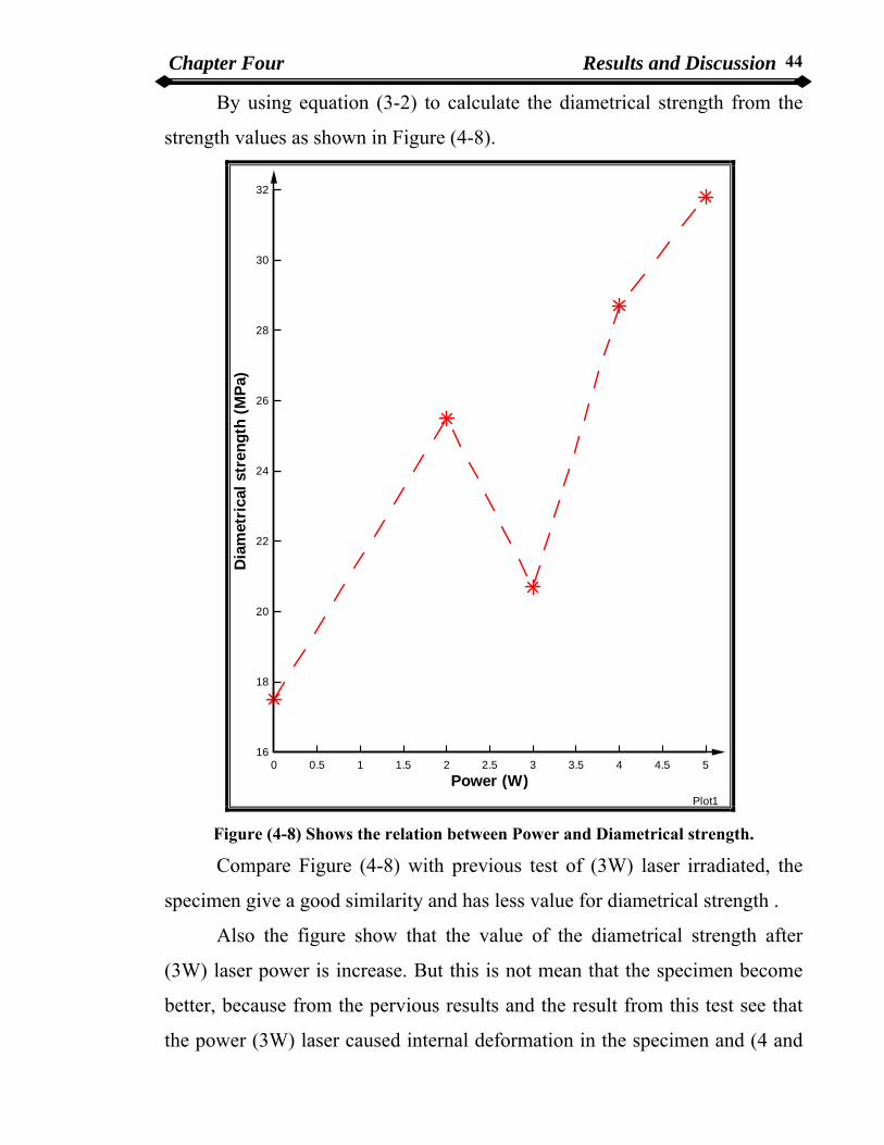
By using equation (3-2) to calculate the diametrical strength from the
strength values as shown in Figure (4-8).
Plot1
Power (W)
Dia
met
rica
l str
engt
h (M
Pa)
0 0.5 1 1.5 2 2.5 3 3.5 4 4.5 516
18
20
22
24
26
28
30
32
Figure (4-8) Shows the relation between Power and Diametrical strength.
Compare Figure (4-8) with previous test of (3W) laser irradiated, the
specimen give a good similarity and has less value for diametrical strength .
Also the figure show that the value of the diametrical strength after
(3W) laser power is increase. But this is not mean that the specimen become
better, because from the pervious results and the result from this test see that
the power (3W) laser caused internal deformation in the specimen and (4 and

Chapter Four Results and Discussion 45
5) Watt laser temperature caused glazed in the specimens covered internal
deformation. And this gazed layer is weak not give a strength to the
specimens, it will be more exposed to break and this will weaken the
mechanical properties of the specimens, so that not choose the higher powers
over (2W) laser, but would considered (2W) laser stroked was the best power
at all.
The Figure (4-9) shows the shape of the specimens after the diametrical
strength was done.
2W 3W 4W 5W
Figure 4-9 Shows the broken specimen after diametrical loaded is applied.
4.5 Density and porosity calculation In this section firstly, calculate the porosity of the specimens which is
irradiated by (2, 3, 4, and 5) Watt laser power. In porosity measurement,
calculate the weight of the specimens when they are dry, soaked and
immersed, the results are shown in table (4-4). Table 4-4 Power and dry, soaked, immersed specimens weight.
Power (W) Dry specimens
weight (g)
Soaked specimens
weight (g)
Immersed specimens
weight (g)
0 1.22 1.25 0.72
2 1.48 1.53 0.88
3 1.34 1.37 0.81
4 1.40 1.43 0.83
5 1.43 1.45 0.87

Chapter Four Results and Discussion 46
Equation (3-6) was used to calculate the ratio of porosity listed in table (4-5). Table 4-5 power and apparent porosity.
Power (W) Apparent porosity (%)
0 5.73
2 7.69
3 5.53
4 5.28
5 3.53
Figure (4-10) shows this ratio.
Plot1
Power (W)
App
aren
t Por
osity
(%)
0 0.5 1 1.5 2 2.5 3 3.5 4 4.5 53.5
4
4.5
5
5.5
6
6.5
7
7.5
8
Figure (4-10) Power and porosity.
Chapter Four Results and Discussion 47
The figure show a higher value of porosity at (2W) laser, because of no
internal deformation occur in the specimen. After (2W) laser the value of
porosity is decreased because of the internal deformation occur at (3W) laser
and glazed layer consisting in (4,5) Watt which make the specimens less
porous value.
Porosity is almost present in ceramics prepared by powder compaction
and heat treatment. Porosity is an important parameter to characterize ceramic
microstructures, as are grain size, grain shape and phase arrangement. Since
properties of materials depend on their microstructure, this article will recall
the main features of the porosity effects on the mechanical properties of
ceramics. Specific attention will be paid to technical ceramics and the main
interest will be devoted to thermal shock resistance, which largely determines
the in-service life time of these materials.
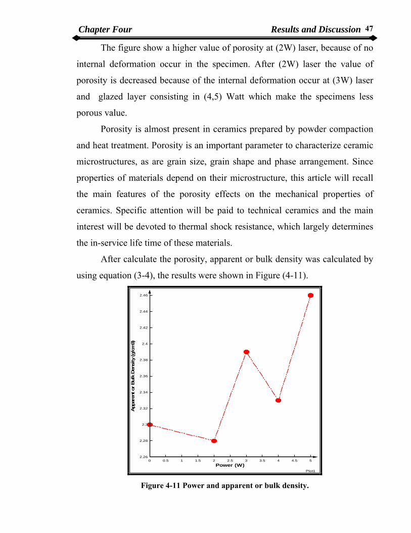
After calculate the porosity, apparent or bulk density was calculated by
using equation (3-4), the results were shown in Figure (4-11).
Plot1
Power (W)
App
aren
t or Bul
k Den
sity
(g/c
m3)
2.46
2.44
2.42
2.4
2.38
2.36
2.34
2.32
2.3
2.28
0 0.5 1 1.5 2 2.5 3 3.5 4 4.5 52.26
Figure 4-11 Power and apparent or bulk density.

Chapter Four Results and Discussion 48
Calculate the apparent-solid (sintered) density by using equation (3-5),
the results were shown in the Figure (4-12).
Plot1
Power (W)
App
aren
t-So
lid (s
inte
red)
Den
sity
(g/c
m3)
0 0.5 1 1.5 2 2.5 3 3.5 4 4.5 52.44
2.45
2.46
2.47
2.48
2.49
2.5
2.51
2.52
2.53
2.54
2.55
Figure (4-12) Power and apparent- solid (sintered) density.
The results from power and density test are listed in table (4-6).
Chapter Four Results and Discussion 49
Table 4-6 power , apparent or bulk density, and apparent solid density.
Power (W) Apparent or bulk
density (g/cm3)
Apparent- solid (sintered)
density (g/cm3)
0 2.3 2.44
2 2.28 2.47
3 2.39 2.53
4 2.33 2.46
5 2.46 2.55
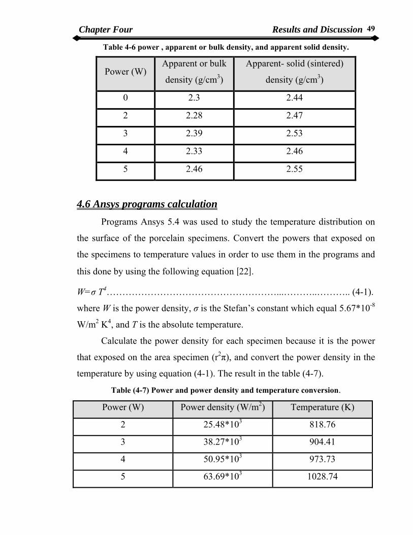
4.6 Ansys programs calculation
Programs Ansys 5.4 was used to study the temperature distribution on
the surface of the porcelain specimens. Convert the powers that exposed on
the specimens to temperature values in order to use them in the programs and
this done by using the following equation [22].
W=σ T4………………………………………………...………..……….. (4-1).
where W is the power density, σ is the Stefan’s constant which equal 5.67*10-8
W/m2 K4, and T is the absolute temperature.
Calculate the power density for each specimen because it is the power
that exposed on the area specimen (r2π), and convert the power density in the
temperature by using equation (4-1). The result in the table (4-7).
Table (4-7) Power and power density and temperature conversion.
Power (W) Power density (W/m2) Temperature (K)
2 25.48*103 818.76
3 38.27*103 904.41
4 50.95*103 973.73
5 63.69*103 1028.74

Chapter Four Results and Discussion 50
To calculate the heat treated by using the programs, listed the values of
the density, thermal conductivity, and specific heat for specimen. The thermal
conductivity and specific heat were choose from standard tables which are
equal [0.07166 (W/m.K) and 578.611 (J/Kg.K)] respectively.
The density is calculated from the previous test, as shown in table (4-6).
The procedure and the Ansys user Guide show in appendix B.
Calculate the temperature distribution of the specimens with dimension
(4*10 mm) which have the same thermal conductivity and specific heat and
have density is 2.48 (g/cm3) from the standard table for all the specimens.
The results of the Ansys programs are show in the following Figures.
Figures (4-13, 14, 15, 16) are the result of (4*10mm) specimens irradiated by
(2, 3, 4, and 5) Watt respectively.
Figure (4-13) Temperature distribution of the specimen of 2W.

Chapter Four Results and Discussion 51
Figure (4-14) Temperature distribution of the specimen of 3W.
Figure (4-15) Temperature distribution of the specimen of 4W.

Chapter Four Results and Discussion 52
Figure (4-16) Temperature distribution of the specimen of 5W.
Figure (4-17, 18, 19, 20) show that the results of the (6*10mm)
specimen irradiated by (2,3,4, and 5)Watt respectively.
Figure (4-17) Temperature distribution of the specimen irradiated by 2W

Chapter Four Results and Discussion 53
Figure (4-18) Temperature distribution of the specimen of 3W.
Figure (4-19) Temperature distribution of the specimen irradiated by 4W

Chapter Four Results and Discussion 54
Figure (4-20) Temperature distribution of the specimen irradiated by 5W.
These Figures shown that the different area divided according to the
value of exposed heat which produced from strike of the laser beam on the
surface of the porcelain specimens. Its also observe that the red area was the
higher thermal area on the specimens surfaces, and this area increased
gradually due to the increase in the incident power that exposed on the surface
of the specimens.
Then a specimen was irradiated it by (10W) laser, which is equal to the
temperature value (1200 K), we observe that the specimen was broken
because the specimen withstand higher temperature and this is indicated that
the porcelain specimen break or crack may occur inside it in higher power
laser as it shown in (3,4,and 5) Watt laser, also (10W) laser the specimen was
break and this will support the present results it can be consider that the (2W)
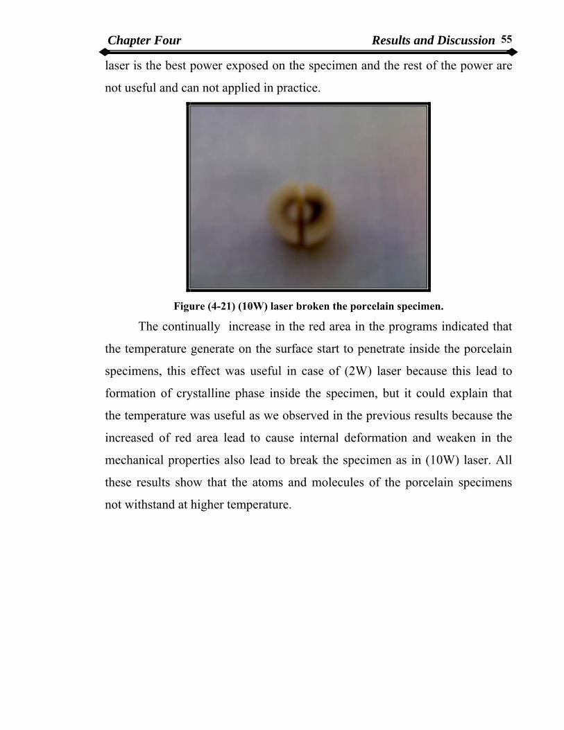
Chapter Four Results and Discussion 55
laser is the best power exposed on the specimen and the rest of the power are
not useful and can not applied in practice.
Figure (4-21) (10W) laser broken the porcelain specimen.
The continually increase in the red area in the programs indicated that
the temperature generate on the surface start to penetrate inside the porcelain
specimens, this effect was useful in case of (2W) laser because this lead to
formation of crystalline phase inside the specimen, but it could explain that
the temperature was useful as we observed in the previous results because the
increased of red area lead to cause internal deformation and weaken in the
mechanical properties also lead to break the specimen as in (10W) laser. All
these results show that the atoms and molecules of the porcelain specimens
not withstand at higher temperature.

Chapter Five Conclusions and Future Works 56
Chapter Five Conclusions and Future Works
5.1 Conclusions The important facts derived from the practical results at this work can
be summarized as follows:
1. The laser surfaces Harding for porcelain material change the physical
and mechanical properties.
2. The CO2 laser is well suited for the treatment of porcelain materials
because its emission wavelength is almost totally absorbed by
porcelain.
3. The value of porosity decreased after irradiation by (2W) laser because
of the glazed layer.
4. By compare powers (2, 3, 4, 5) watt it is noted that the (2W) laser is the
better laser power than other power.
5. For laser Harding on other hand, the surface temperature should be as
high as possible with shortens time to complete the transformation and
to heat a sufficient thick surface layer in a short time. A short time and
high temperature gradients are also required to prevent heating of the
bulk material and avoid break in the porcelain specimens.
6. The specimens irradiated by (3W) laser internal deformation occur
inside the specimen will reduce the mechanical properties of the
material.
7. Ansys 5.4 programs showed effect of temperature distribution
instantaneous from the specimens surface and the temperature penetrate
inside the specimens.

Chapter Five Conclusions and Future Works 57
5.2 Future work A number of future works can be suggested depending on the practical
results of this thesis, these include the following points:
1. Using more than (10) specimens to irradiated by different laser power.
2. Study other laser device with different wavelength which can use in
temperature distribution to show a different influence on the porcelain
specimens.
3. Study the effect of changing irradiation time on the specimen for
different specimens size.
4. Study the surface morphology by using scanning electron microscope
(SEM).
5. Study the penetration depth of heat inside the specimens for different
specimens thickness.

III
CONTENTS
3.4.1 Determination of Crystal Phase Method. 28 3.5 Degree of Crystalline Procedure. 28 3.6 Mechanical Properties Measurements. 29 3.6.1 Micro-Hardness Procedure. 29 3.6.2 Diametrical Strength Procedure. 30 3.7 Density and Porosity. 32 3.8 Ansys Programs. 33
Acknowledgment. I Abstract. II Contents. III List of Figures. V List of Tables. VII List of Abbreviations. VIII List of Symbols. X
CHAPTER ONE : Introduction and Historical Review 1.1 Introduction. 1 1.2 Review of Literature. 2
1.2.1 Laser in Dentistry. 2 1.3 Aim of the Work. 4
CHPTER TWO : Theory Background 2.1 Laser Applications. 5 2.2 Laser matter interaction. 9 2.3 Laser Material Processing. 10 2.4 Carbon Dioxide Laser. 11 2.4.1 Lasing Medium. 12 2.5 Dental Materials. 14 2.6 Composition of Dental Porcelain. 16 2.6.1 Silica. 19 2.6.2 Feldspar. 19 2.6.3 Kaolin. 20 2.7 Type of Dental Porcelain. 20
CHAPTER THREE: Experimental Parts 3.1 Introduction. 22 3.2 Specimens Preparation Method. 22 3.3 Specimens Irradiation by CO2 Laser. 24
3.4 Crystalline Phase Deformation by Using X-Ray Diffraction Technique. 27
IV
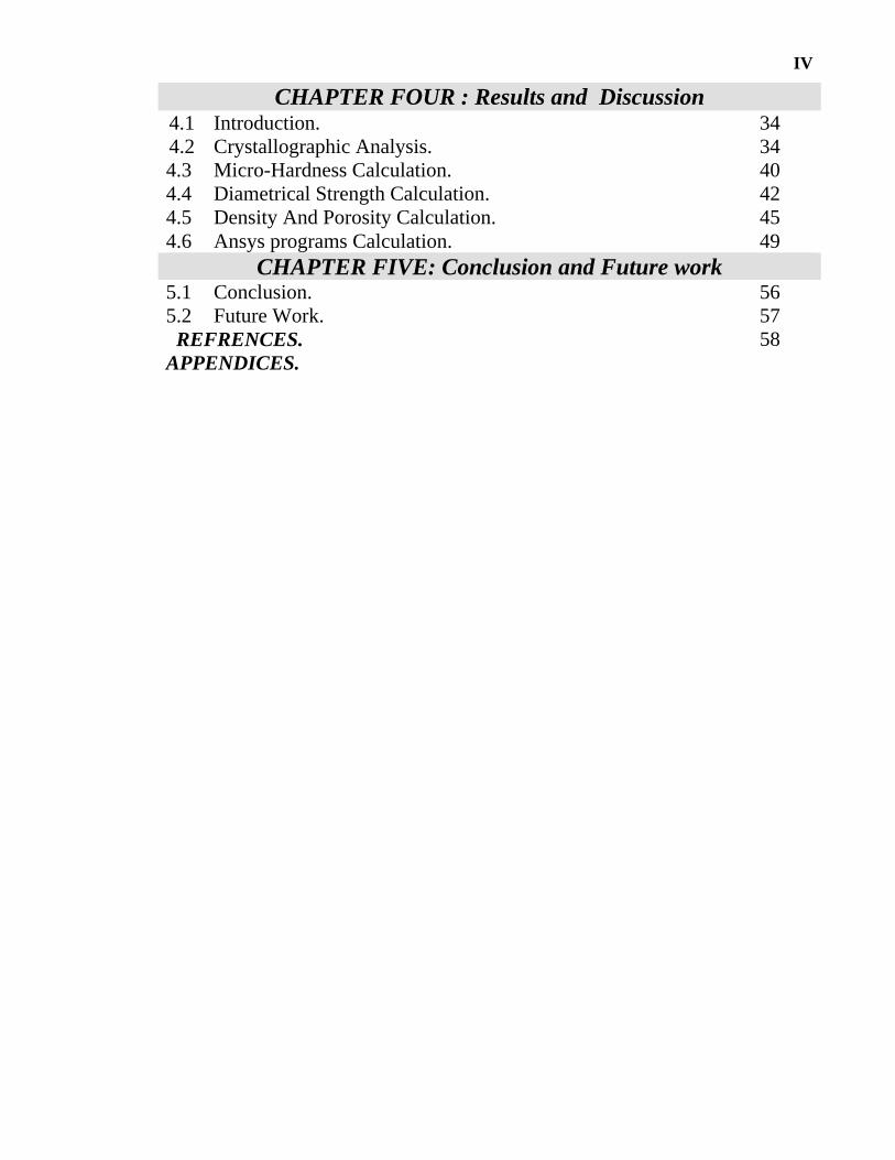
CHAPTER FOUR : Results and Discussion 4.1 Introduction. 34 4.2 Crystallographic Analysis. 34 4.3 Micro-Hardness Calculation. 40 4.4 Diametrical Strength Calculation. 42 4.5 Density And Porosity Calculation. 45 4.6 Ansys programs Calculation. 49
CHAPTER FIVE: Conclusion and Future work 5.1 Conclusion. 56 5.2 Future Work. 57 REFRENCES. 58 APPENDICES.
VIII
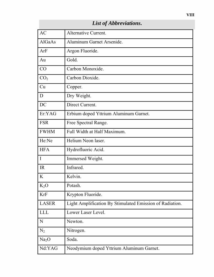
List of Abbreviations.
AC Alternative Current.
AlGaAs Aluminum Garnet Arsenide.
ArF Argon Fluoride.
Au Gold.
CO Carbon Monoxide.
CO2 Carbon Dioxide.
Cu Copper.
D Dry Weight.
DC Direct Current.
Er:YAG Erbium doped Yttrium Aluminum Garnet.
FSR Free Spectral Range.
FWHM Full Width at Half Maximum.
He:Ne Helium Neon laser.
HFA Hydrofluoric Acid.
I Immersed Weight.
IR Infrared.
K Kelvin.
K2O Potash.
KrF Krypton Fluoride.
LASER Light Amplification By Stimulated Emission of Radiation.
LLL Lower Laser Level.
N Newton.
N2 Nitrogen.
Na2O Soda.
Nd:YAG Neodymium doped Yttrium Aluminum Garnet.

IX
OC Output Coupler. oC. Centigrade Degree
OFA Orthophosphoric Acid.
RF Radio Frequency.
S Soaked Weight.
SiO2 Silicate.
TEA Transversely Excited at Atmospheric pressure.
ULL Upper Laser Level.
UV Ultra Violet.
ρb Bulk Density.
ρt True Density.

X
List of Symbols.
∆υ The FWHM of the Output (Hz).
µm Micrometer.
c Speed of Light (3*108 m/s).
cm Centimeter.
D Specimens Diameter(mm).
F Applied Load (N).
I Incident Power Density (W/m2).
Io Absorbed Power Density (W/m2).
J Joule.
k Thermal Conductivity (W/mK).
kW Kilowatt.
L Cavity Length (m).
M Atomic Mass of atom or molecular.
m Meter.
mA Milliampre.
MHz Megahertz.
mm Millimeter.
q Heat Flux (W/m2).
T Temperature (oC or Kelvin).
t Thickness of Specimens (mm).
V Volt.
W Watt.
z Cross-section area (m2).
β Absorption coefficient.
ε Emissivity.

XI
Κ Boltzmann Constant (1.38*10-23 J/K).
λ Wavelength (µm).
σ Stefan-Boltzmann Constant (5.67*10-8 W/m2 K4).

V
List of Figures
2-1 The phase amplitude of an electromagnetic ray …………. 9
2-2 Energy level in the Carbon dioxide laser. 13
2-3 Relative composition of ceramic products based on feldspar 15
3-1 The die. 23
3-2 The furnace. 23
3-3 CO2 laser system. 24
3-4 Experimental setting for CO2 laser. 25
3-5 CO2 power meter device. 25
3-6 Laser aperture alignment. 27
3-7 X-Ray device. 27
3-8 Digital micro-hardness device. 30
3-9 Brazilian test device. 31
3-10 Diametrical strength specimens. 31
4-1 X-Ray diffraction figure for specimen not irradiate by laser. 35
4-2 X-Ray diffraction figure for specimen ….. 36
4-3 X-Ray diffraction figure for specimen …….. 37
4-4 X-Ray diffraction figure for specimen …… 38
4-5 Degree of Crystalline. 39
4-6 The relation between power and micro-hardness. 42
4-7 The relation between power and strength 43
4-8 The relation between power and Diametrical strength. 44
4-9 The broken specimen when diametrical loaded is applied. 45
4-10 Power and Apparent porosity. 46
4-11 Power and apparent or bulk density. 47
4-12 Power and apparent- solid (sintered) density. 48

VI
4-13 Temperature distribution of the specimen of 2W. 50
4-14 Temperature distribution of the specimen of 3W. 51
4-15 Temperature distribution of the specimen of 4W. 51
4-16 Temperature distribution of the specimen of 5W. 52
4-17 Temperature distribution of the specimen of 2W. 52
4-18 Temperature distribution of the specimen of 3W 53
4-19 Temperature distribution of the specimen of 4W 53
4-20 Temperature distribution of the specimen of 5W 54
4-21 (10W) Laser broken the porcelain specimen 55

VII
List of Table 2-1 Application spectrum of laser. 6
2-2 Commercially available lasers and their industrial applications.
8
2-3 Classification of laser material processing. 10
2-4 Composition of various types of porcelain. 16
2-5 Composition of high, medium, and low fusing porcelain. 17
2-6 Mineral composition for the early dental porcelain. 18
2-7 Typically low fusing dental porcelain composition. 18
3-1 Composition of dental porcelain. 22
3-2 Current/power calibration. 26
4-1 power and degree of crystalline. 40
4-2 power and micro-hardness. 41
4-3 power, strength, and diametrical strength. 43
4-4 Power and dry, soaked, immersed specimens weight. 45
4-5 power and apparent porosity. 46
4-6 power , apparent or bulk density, and apparent solid density. 49
4-7 Power and power density and temperature conversion. 49
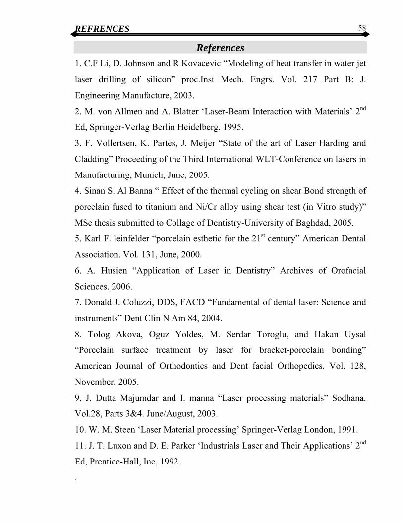
REFRENCES 58
References
1. C.F Li, D. Johnson and R Kovacevic “Modeling of heat transfer in water jet
laser drilling of silicon” proc.Inst Mech. Engrs. Vol. 217 Part B: J.
Engineering Manufacture, 2003.
2. M. von Allmen and A. Blatter ‘Laser-Beam Interaction with Materials’ 2nd
Ed, Springer-Verlag Berlin Heidelberg, 1995.
3. F. Vollertsen, K. Partes, J. Meijer “State of the art of Laser Harding and
Cladding” Proceeding of the Third International WLT-Conference on lasers in
Manufacturing, Munich, June, 2005.
4. Sinan S. Al Banna “ Effect of the thermal cycling on shear Bond strength of
porcelain fused to titanium and Ni/Cr alloy using shear test (in Vitro study)”
MSc thesis submitted to Collage of Dentistry-University of Baghdad, 2005.
5. Karl F. leinfelder “porcelain esthetic for the 21st century” American Dental
Association. Vol. 131, June, 2000.
6. A. Husien “Application of Laser in Dentistry” Archives of Orofacial
Sciences, 2006.
7. Donald J. Coluzzi, DDS, FACD “Fundamental of dental laser: Science and
instruments” Dent Clin N Am 84, 2004.
8. Tolog Akova, Oguz Yoldes, M. Serdar Toroglu, and Hakan Uysal
“Porcelain surface treatment by laser for bracket-porcelain bonding”
American Journal of Orthodontics and Dent facial Orthopedics. Vol. 128,
November, 2005.
9. J. Dutta Majumdar and I. manna “Laser processing materials” Sodhana.
Vol.28, Parts 3&4. June/August, 2003.
10. W. M. Steen ‘Laser Material processing’ Springer-Verlag London, 1991.
11. J. T. Luxon and D. E. Parker ‘Industrials Laser and Their Applications’ 2nd
Ed, Prentice-Hall, Inc, 1992.
.

REFRENCES 59
12. M. Csele “Fundamentals of Light Sources and Lasers” John Wiley & Sons
INC, 2004.
13. Mahir Mustafa Al-Naami “Profilometric study of the surface
characteristics of porcelain using different Glazing and Polishing techniques”
MSc thesis submitted to Collage of Dentistry-University of Baghdad, 1999.
14. Khalid A. Al-Jaafari “Evaluation of the Shear Bond Strength of the
intraoral porcelain repair systems with different surface treatment” MSc thesis
submitted to College of Dentistry- University of Baghdad, 2002.
15. R. G. Craig and J. M. Powers ‘Restorative Dental Materials’
11th Edition Mosby, Inc, 2002.
16. " للمواد الزجاجية المستخدمة في تثبيت النفايات المشعة ةدراسة الخواص الفيزيائي"كاظم عبد حبيتر
1986الجامعة التكنولوجية -م التطبيقيةرسالة ماجستير مقدمة إلى قسم العلو
17. Sheahab Ahmed Zeidan “Bonded Silicon Carbide With Iraqi Clays” Dr
thesis submitted to School of Applied Sciences-University of Technology,
2005.
18. M. Novotna, A. Klouzkov, J. Maixner, V. Satava “Preparation of Leucite
Powders With Controlled Particle Size Distribution” Ceramics-Silikaty 49(4)
252-258, 2005.
19. J. Maixner, A. Klouzkova, M. Mrazova “X-Ray Phase analysis in Leucite
systems” European powder Diffraction conference, EPDIC10, 2007.
20. M. Novotna, J. Maixner “X-Ray powder diffraction study of Leucite
crystallization” European powder Diffraction conference, EPDIC9, 2006.
21. V. Satava, A. Klouzkov, D. Lezal, M. Novotna “Leucite porcelain”
Ceramics-Silikaty 46(1) 37-40, 2002.
22. J. Wilson and J.F.B. Hawkes ‘Optoelectronics an Introduction’ 2nd Ed,
Prentice-Hall, 1989.
23. Robert G. Craig, William M. O’Brien, J. M. Powers ‘Dental Materials ’
6th Ed, Mosoby-Year Book, 1996.