development of in-process welding current and electrode
TRANSCRIPT

92Copyright © 2015 JFE Steel Corporation. All Rights Reserved.
Abstract:Indirect resistance spot welding process with single-
side electrode access was developed for the automotive applications. The variable welding current and elec-trode force control process during welding were studied in order to achieve the promotion of molten nugget for-mation and suppression of expulsion without sacrificing the productivity and design flexibility of automobiles. Numerical simulations were conducted to compare the difference in the welding phenomena between the con-stant pattern of current and force during welding, as the conventional process, and variable control pattern, as the developed processes. It was predicted that the vari-able control pattern has effects on accelerating nugget formation and suppressing expulsion. The welding experiments were subsequently performed on lapped test coupons of 0.7 mm thick cold-rolled steel sheet with ten-sile strength of 270 N/mm2 and 1.6 mm thick cold-rolled steel sheet with tensile strength of 980 N/mm2. When welding was performed with the constant current and force pattern, the appropriate current range was less than 1 kA. On the other hand, it extended to 2.6 kA dur-ing welding with the variable control pattern, confirm-ing the fact that the variable control pattern successfully suppressed the expulsion and acceleration of the nugget formation.
1. Introduction
In automobile body production, a welding process
which enables lapped sheet welding by a work process from one side is desired in order to realize weight reduc-tion and high rigidity in the auto body or to reduce pro-duction costs. Arc welding, laser welding, resistance spot welding, and others may be mentioned as welding processes of this type. Arc welding is used in parts where resistance spot welding cannot be applied because it is not possible to have access from both sides in the existing automobile manufacturing process, but the cost of operation and maintenance, for example, for removal of spatter from around the welding torch, is an issue. In the case of laser welding, the high initial investment cost is a major barrier to practical application. As resistance spot welding processes, series type1–5) and indirect type6–14) processes have been developed as processes that enable single-side welding. As it is possible to pro-cure the welding systems at an initial investment cost at the same level as conventional resistance spot welding, their commercial feasibility is excellent. Therefore, high expectations are placed on practical application of both types.
The series type is a welding process in which two electrodes are applied to lapped sheet members from one side, and welding is performed simultaneously at two points by passing a current between the electrodes. However, current conduction tends to be large in the member on the side in contact with the electrodes, while conduction between the lapped sheet members is small. Consequently, it has been reported that the heat gener-ated between the lapped portion is small, and molten
JFETECHNICALREPORTNo.20(Jan.2015)
Development of In-Process Welding Current and Electrode Force Control Process for Single-Side Resistance Spot Welding†
MATSUSHITA Muneo*1 IKEDA Rinsei*2 OI Kenji*3
† Originally published in JFE GIHO No. 34 (Aug. 2014), p. 22–27 *2 Dr. Eng., Senior Researcher General Manager, Joining & Strength Res. Dept., Steel Res. Lab., JFE Steel
*1 Ph. D., Senior Researcher Manager, Joining & Strength Res. Dept., Steel Res. Lab., JFE Steel
*3 Dr. Eng., General Manager, Joining & Strength Res. Dept., Steel Res. Lab., JFE Steel

JFETECHNICALREPORTNo.20(Jan.2015) 93
Development of In-Process Welding Current and Electrode Force Control Process for Single-Side Resistance Spot Welding
nugget is difficult to be formed2,3).On the other hand, in the indirect type, one electrode
is pressed on the lapped sheet members from one side, a ground electrode is attached at a point different from the weld point, and welding is performed by current con-duction between the welding electrode and ground elec-trode. A molten nugget is easily obtained by Joule heat because the current passes across the lapped sheet mem-bers at the weld point. However, since the shunting con-dition changes greatly depending on the thickness of the members, the presence of existing welds, and other fac-tors, the diameter of the formed nuggets is also greatly influenced9,11). To overcome this problem, methods involving the welding conditions, position of the ground electrode, welding sequence, and combination of steel sheets have been reported7,9,10).
This paper introduces a new welding process12–14) which was developed by focusing on variable control of the welding current and electrode force during welding in indirect type single-side resistance spot welding. Although this type of variable control had not been stud-ied in the past, with the newly-developed process enables to obtain stable nugget formation in spite of changes in the shunting condition and to suppress expul-sion. First, the welding conditions for promoting nugget formation and suppressing expulsion were predicted by numerical simulation. The possibility of expanding the range of appropriate welding conditions under a large shunting condition by applying the variable welding cur-rent and electrode force process was then verified exper-imentally.
2. ExperimentalMethod
2.1 NumericalSimulation
A numerical simulation was performed using the general-purpose program “SORPAS®” (SWANTEC Software and Engineering ApS). The analysis was car-ried out with a two dimensional axisymmetric model (thermo-elastic-plastic finite element method). Calcula-tions considered the sheet thickness and temperature dependency of the physical properties of the electrode material (thermal conductivity, specific heat, electrical conductivity, Young’s modulus, coefficient of linear thermal expansion). Figure1 shows the model for the numerical simulation of single-side spot welding. The simulation assumed welding of a lapped member con-sisting of a 0.7 mm thick 270 N/mm2 class cold-rolled steel sheet as the top sheet, and a 1.6 mm thick 980 N/mm2 class cold-rolled steel sheet as the bottom sheet.
The top electrode was the welding electrode and had an R shape with a tip curvature radius of 40 mm. The lapped steel sheets were arranged in a condition without
restraint on top of a hollow conductive object with a concave-shaped cross section and were supported at their edges. The distance between the edges of supports was 50 mm. The bottom electrode, which functioned as the ground electrode, was a flat-shaped tip type. The welding current and electrode force used in the simula-tion were the constant current and force pattern (conven-tional welding process) shown in Fig.2 and the variable current and force pattern (developed welding process) shown in Fig.3. The change over time in the tempera-ture distribution and current density distribution of the weld during current conduction were calculated under these conditions, and the fusion zone formation process and heat generation condition were estimated.
Fig. 1 Models for numerical simulation for single-side spot welding
Fig. 2 Welding conditions of constant current and force pattern
Fig. 3 Welding conditions variable current and force pattern
94 JFETECHNICALREPORTNo.20(Jan.2015)
Development of In-Process Welding Current and Electrode Force Control Process for Single-Side Resistance Spot Welding
2.2 WeldingExperiments
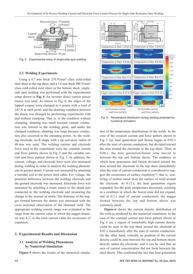
Using a 0.7 mm thick 270 N/mm2 class cold-rolled steel sheet as the top sheet, and a 1.6 mm thick 980 N/mm2 class cold-rolled steel sheet as the bottom sheet, single-side spot welding was performed with the experimental setup shown in Fig.4. An inverter direct current power source was used. As shown in Fig. 4, the edges of the lapped coupon were clamped at 4 points with a load of 245 N at each point, and the shunting condition between the sheets was changed by performing experiments with and without clamping. That is, in the condition without clamping, shunting was small because current conduc-tion was limited to the welding point, and under the clamped condition, shunting was large because conduc-tion also occurred at the clamping points. As the weld-ing electrode, an R shape with a tip curvature radius of 40 mm was used. The welding current and electrode force used in the experiment were the constant current and force pattern shown in Fig. 2 and the variable cur-rent and force pattern shown in Fig. 3. In addition, the current, voltage, and electrode force were also measured during welding in order to analyze the welding phenom-ena in greater detail. Current was measured by attaching a toroidal coil to the power feed cable. For voltage, the potential difference between the welding electrode and the ground electrode was measured. Electrode force was measured by attaching a strain sensor to the shank part connected to the welding electrode and measuring the change in the amount of strain. The diameter of the nug-get formed between the sheets was measured with the cross sectional observation of the obtained weld. The appropriate welding current range was evaluated as the range from the current value at which the nugget diame-ter was 4 t to the limit current value for occurrence of expulsion.
3. ExperimentalResultsandDiscussion
3.1 AnalysisofWeldingPhenomenabyNumericalSimulation
Figure5 shows the results of the numerical simula-
tion of the temperature distributions of the welds. In the case of the constant current and force pattern shown in Fig. 5 (a), heat generation and fusion began at 0.02 s after the start of current conduction, but deviated toward the area around the electrode in the top sheet. Then, at 0.06 s, the heat generation/fusion zone moved to between the top and bottom sheets. The tendency in which heat generation and fusion deviated toward the area around the electrode in the top sheet immediately after the start of current conduction is considered to sug-gest the occurrence of surface expulsion15), that is, scat-tering of molten metal from the surface of weld around the electrode. At 0.12 s, the heat generation region expanded, but the peak temperature decreased, resulting in a condition in which the fusion zone did not expand, and at 0.3 s (end of current conduction), the nugget formed between the top and bottom sheets was extremely small.
Figure6 shows the current density distribution of the weld as predicted by the numerical simulation. In the case of the constant current and force pattern shown in Fig. 6 (a), a region of remarkably high current density could be seen in the top sheet around the electrode at 0.02 s immediately after the start of current conduction. On the other hand, virtually no gradient of the current density could be seen between the top and bottom sheets directly under the electrode, and it can be said that an area of current concentration did not form between the steel sheets. This confirmed the fact that heat generation
Fig. 4 Experimental setup of single-side spot welding
Fig. 5 Temperature distribution during welding predicted by numerical simulation

JFETECHNICALREPORTNo.20(Jan.2015) 95
Development of In-Process Welding Current and Electrode Force Control Process for Single-Side Resistance Spot Welding
and fusion deviated toward the area around the electrode in the initial period of current conduction, as observed in Fig. 5 (a), because heat generation at the contact point between the electrode and the top sheet was prevailing, and heat generation by current conduction between the top and bottom sheets was extremely small. Next, at 0.06 s, a region of high current density accompanied by a continuous gradient between the top and bottom sheets could be seen directly under the electrode; thus, the cal-culation displayed a condition in which a conduction path had formed between the top and bottom sheets. At 0.06 s, it is considered that the weld had shifted to a condition in which heat generation and fusion occurred between the top and bottom sheets. Then, as can be seen at 0.08 and 0.12 s, the conduction path expanded, and accompanying this, the current density decreased. There-fore, as could be seen in Fig. 5 (a), although the heat generation region expanded, the peak temperature decreased, and as a result, the fusion zone did not expand.
As may be surmised from these results, in single-side spot welding, the temperature distribution and current density distribution change constantly over the course of time from the start to the end of current conduction, and for this reason, it is not possible to optimize the welding conditions for the respective time periods if the current and electrode force are held constant. Therefore, the possibility of suppressing expulsion and accelerating nugget formation by selecting the optimum conditions
for two time periods, divided into the initial period and the later period of current conduction, was studied by using a numerical simulation.
It is considered that an expulsion suppression effect and nugget formation promotion effect can be obtained by the following mechanism by using a variable current and force control pattern like that shown in Fig. 3. In the 1st stage, the steel sheets are heated while loaded with an adequate electrode force by applying low current and high force. This ensures a sufficient contact area between the electrode and the surface of the top sheet. Surface expulsion due to excessive concentration of the welding current around the electrode can be suppressed, and a conduction path is ensured by formation of a tight interface between the top and bottom sheets. Then, in the 2nd stage, high current and low force is applied, thereby increasing the current density of the conduction path that was formed in the 1st stage and promoting heat generation from between the top and bottom sheets. Expansion of the contacting diameter between the top and bottom sheets is avoided by reducing the electrode force; this reduces the decrease in current density that occurs under high electrode force, and as a result, it is possible to promote nugget formation.
Figure 5 (b) shows the results of the numerical simu-lation of the temperature distribution for the variable current and force control pattern. In the 1st stage, heat generation was on a level that did not cause fusion, as seen 0.02 and 0.06 s. However, at 0.12 s, immediately after the start of the 2nd stage, a fusion zone was formed by heat generation from between the top and bottom sheets, and at 0.3 s, a nugget with a large diameter of 5 mm had formed between the top and bottom sheets.
Figure 6 (b) shows the current density distribution with the variable current and force control pattern. In the 1st stage with the electrode force is high and the weld-ing current is low, a conduction path can be formed while maintaining a low current density around the elec-trode, as seen at 0.02 and 0.06 s. In the 2nd stage with the electrode force is low and the current is high, a high current density is loaded on the conduction path formed in the 1st stage, and the calculation displays a heat gen-eration condition in which heat generation and fusion occur between the top sheet and the bottom sheet. At 0.12 s, expansion of the conduction path is suppressed and a high current density is maintained. It is thought that a large expansion of the fusion zone is achieved as a result of this condition.
From the above, the expulsion suppression effect and nugget formation promotion effect of the variable cur-rent and force control pattern were predicted by using the numerical simulation.
Fig. 6 Current density distribution during welding predicted by numerical simulation

96 JFETECHNICALREPORTNo.20(Jan.2015)
Development of In-Process Welding Current and Electrode Force Control Process for Single-Side Resistance Spot Welding
3.2 VerificationbyWeldingExperiments
Figure7 shows the effects of electrode force, weld-ing current, and shunting (with or without clamping) on nugget formation during actual welding by the constant current and force pattern shown in Fig. 2, when the shunting condition was changed by clamping or not clamping the lapped coupons. As shown in Fig. 7 (a), under the electrode force of 400 N, the nugget diameter showed a tendency to increase as the current increased. However, at 8 kA, the nugget diameter decreased, accompanied by expulsion. This is considered to be the result of scattering of the molten metal to the outside due to expulsion. If the range from the current value at which the nugget diameter is 4 t to the limit current value for occurrence of expulsion is defined as the appropriate welding current range, the appropriate range without clamping is on the order of 3 kA, i.e., from approximately 5 kA to less than 8 kA. With clamping, the nugget shows a tendency to become smaller in com-parison with that at the same current value without clamping, and the appropriate welding current range is no more than 1 kA. Fig. 7 (b) shows the nugget diameter when the electrode force is increased under a constant current of 7 kA. Because expulsion occurs at the elec-trode force of 200 N, the nugget diameter decreased in
comparison with the force of 400 N. On the other hand, when electrode force was 400 N or more, expulsion did not occur, but the nugget diameter decreased as elec-trode force increased. Although the tendency was the same regardless of whether clamping was applied or not, the decrease in the nugget was remarkable under the condition of large shunting when clamping was applied, as shown in the cross-sectional macrostructure in Photo1. From the above, when shunting is small under the unclamped condition, a wide appropriate welding current range can be obtained with the constant current and force pattern, and satisfactory welding is possible. However, when shunting is large under the clamped condition, the appropriate welding current range becomes extremely narrow, and the results confirmed that satisfactory welding is difficult.
Figure8 shows the results of welding with the vari-able current and force control pattern shown in Fig. 3. As the variable current and force control pattern, the 1st stage conditions were set at either current of 2 kA and force of 600 N or current of 4 kA and force of 800 N, and the 2nd stage conditions were set at force of 400 N and current of 5 to 9 kA. To evaluate nugget formation
Fig. 7 Welding results of constant current and force pattern
Photo 1 Cross-sectional macrostructures of the welds with constant current and force pattern (7 kA of current and 400 N of force)
Fig. 8 Welding results of variable current and force pattern (With clamping)
JFETECHNICALREPORTNo.20(Jan.2015) 97
Development of In-Process Welding Current and Electrode Force Control Process for Single-Side Resistance Spot Welding
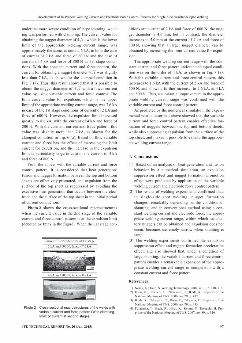
ditions are current of 2 kA and force of 600 N, the nug-get diameter is 4.6 mm, but in contrast, the diameter increases to 5.0 mm at the current of 4 kA and force of 800 N, showing that a larger nugget diameter can be obtained by increasing the limit current value for expul-sion.
The appropriate welding current range with the con-stant current and force pattern under the clamped condi-tion was on the order of 1 kA, as shown in Fig. 7 (a). With the variable current and force control pattern, this increases to 1.6 kA with the current of 2 kA and force of 600 N, and shows a further increase, to 2.6 kA, at 4 kA and 800 N. Thus, a substantial improvement in the appro-priate welding current range was confirmed with the variable current and force control pattern.
As predicted by the numerical simulation, the experi-mental results described above showed that the variable current and force control pattern enables effective for-mation of nuggets between the top and bottom sheets, while also suppressing expulsion from the surface of the top sheet, and makes it possible to expand the appropri-ate welding current range.
4. Conclusions
(1) Based on an analysis of heat generation and fusion behavior by a numerical simulation, an expulsion suppression effect and nugget formation promotion effect were predicted by application of the variable welding current and electrode force control pattern.
(2) The results of welding experiments confirmed that, in single-side spot welding, nugget formation changes remarkably depending on the condition of shunting, and in conventional method using a con-stant welding current and electrode force, the appro-priate welding current range, within which satisfac-tory nuggets can be obtained and expulsion does not occur, becomes extremely narrow when shunting is large.
(3) The welding experiments confirmed the expulsion suppression effect and nugget formation acceleration effect, and also showed that, under a condition of large shunting, the variable current and force control pattern enables a remarkable expansion of the appro-priate welding current range in comparison with a constant current and force pattern.
References 1) Noma, K.; Kato, S. Welding Technology. 2004, no. 1, p. 110–116. 2) Hirai, K.; Takeuchi, H.; Nakagaito, T.; Ikeda, R. Preprints of the
National Meeting of JWS. 2006, no. 79, p. 432. 3) Ikeda, R.; Nakagaito, T.; Hirai, K.; Takeuchi, H. Preprints of the
National Meeting of JWS. 2006, no. 79, p. 433. 4) Futatsuka, T.; Ikeda, R.; Hirai, K.; Kenmi, T.; Takeuchi, H. Pre-
prints of the National Meeting of JWS. 2007, no. 80, p. 316.
under the more severe condition of large shunting, weld-ing was performed with clamping. The current value for obtaining the nugget diameter of 4 t , which is the lower limit of the appropriate welding current range, was approximately the same, at around 6 kA, in both the case of current of 2 kA and force of 600 N and the case of current of 4 kA and force of 800 N as 1st stage condi-tions. With the constant current and force pattern, the current for obtaining a nugget diameter 4 t was slightly less than 7 kA, as shown for the clamped condition in Fig. 7 (a). Thus, this result showed that it is possible to obtain the nugget diameter of 4 t with a lower current value by using variable current and force control. The limit current value for expulsion, which is the upper limit of the appropriate welding current range, was 7.6 kA in case of the 1st stage conditions of current of 2 kA and force of 600 N. However, the expulsion limit increased greatly, to 8.8 kA, with the current of 4 kA and force of 800 N. With the constant current and force pattern, this value was slightly more than 7 kA, as shown for the clamped condition in Fig. 6 (a). Based on this, variable current and force has the effect of increasing the limit current for expulsion, and the increase in the expulsion limit is particularly large in case of the current of 4 kA and force of 800 N.
From the above, with the variable current and force control pattern, it is considered that heat generation/fusion and nugget formation between the top and bottom sheets are effectively promoted, and expulsion from the surface of the top sheet is suppressed by avoiding the excessive heat generation that occurs between the elec-trode and the surface of the top sheet in the initial period of current conduction.
Photo2 shows the cross-sectional macrostructures when the current value in the 2nd stage of the variable current and force control pattern is at the expulsion limit (denoted by Imax in the figure). When the 1st stage con-
Photo 2 Cross-sectional macrostructures of the welds with variable current and force pattern (With clamping, Imax of current at second stage)

98 JFETECHNICALREPORTNo.20(Jan.2015)
Development of In-Process Welding Current and Electrode Force Control Process for Single-Side Resistance Spot Welding
Copyright © 2015 JFE Steel Corporation. All Rights Reserved. Unauthorized reproduction prohibited.
of the National Meeting of JWS. 2009, no. 85, p. 117.11) Kikuchi, S.; Nishibata, H.; Fukumoto, M.; Uchihara, M. Preprints
of the National Meeting of JWS. 2010, no. 87, p. 142.12) Matsushita, M.; Ikeda, R.; Endo, S. Preprints of the National
Meeting of JWS. 2011, no. 88, p. 324.13) Matsushita, M.; Ikeda, R.; Endo, S. Preprints of the National
Meeting of JWS. 2012, no. 90, p. 420.14) Matsushita, M.; Ikeda, R.; Oi, K. Preprints of the National Meet-
ing of JWS. 2013, no. 92, p. 223.15) Matsuyama, K. Welding Technology. 2002, no. 3, p. 93–97.
5) Date, R.; Hirai, K.; Matsushita, M.; Ikeda, R.; Kariya, N. Pre-prints of the National Meeting of JWS. 2009, no. 85, p. 118.
6) Cho, Y.; Chang, I.; Lee, H. Weld. J. 2006, vol. 85, p. 26–29. 7) Hasegawa, Y.; Fujita, K.; Endo, T.; Fujimoto, M.; Tanabe, J.;
Yoshida, M. Honda R & D Technical Review. 2008-10, vol. 20, no. 2, p. 106–113.
8) Furukawa, K. Welding Technology. 2008, no. 3, p. 62–68. 9) Nishibata, H.; Fukumoto, M.; Uchihara, M. Welding in the World.
2009, vol. 53, no. 5/6, p. 15–22.10) Nishibata, H.; Kikuchi, S.; Fukumoto, M.; Uchihara, M. Preprints