development of computer-aided design tools for … · development of computer-aided design tools...
TRANSCRIPT
Development of Computer-Aided Design Tools for Automotive
Batteries
Taeyoung Han General Motors R&D Center
Date: June 17, 2014
Project ID # ES119
This presentation does not contain any proprietary, confidential, or otherwise restricted information 1

Overview Timeline Barriers • Barriers
a) Lack of validated computer-aided engineering tools for accelerating battery development cycle
b) Complexity of multi-scale, multi-physics interactions
• Targets -shorten time and cost for design and development of EDV and HEV battery packs
• Start – June 2011 • Finish – Dec 2014 • 75% Complete
Budget Partners • Total project funding: $7.1 M
—DOE - $ 3,540 K —Contractor – $ 3,540 K
• Funding received —FY 12: $ 1,488 K (6/11 – 12/12) —FY 13: $ 1,267 K (1/13 – 12/13) —Total: $2,755 K
• Funding for FY 14 —$785 K
• GM : End user requirements, verification/validation, project management
• ANSYS : Software dev. and commercialization • ESim : Cell level sub models, life model • NREL : Technical monitor
Project Lead: GM R&D Center
Funding provided by Dave Howell of the DOE Vehicle Technologies Program . The activity is managed by Brian Cunningham of Vehicle Technologies.
Subcontracted by NREL, Gi-Heon Kim Technical Monitor 2

Project Relevance/Objectives: faster design cycles and optimize
batteries (cells and packs) for improved performance, safety, life, and low cost.
Ability to provide trade off studies between various cooling concepts and the battery pack life.
Various cooling
concepts
Liquid cooling
Air coolingCold plate
Virtual
Battery Design
Vehicle Simulator
Vehicle Speed
-10
0
10
20
30
40
50
60
70
80
90
0 100 200 300 400 500 600
Time (s)
Vehicle Speed
Vehicle Driving ProfileVehicle Design
Virtual
0 10 20 30 40 50 60-600
-400
-200
0
200
400
600
800
CD CS
Power Profile
Multi-Scale
Multi-Dimensional
Li-ion Battery Model
Battery ResponsesFeedback
Embedded
Battery Model
Battery Power Profile
Vehicle Driving Cycle
Vehicle Simulator
Virtual
Battery Design
Vehicle Simulator
Vehicle Speed
-10
0
10
20
30
40
50
60
70
80
90
0 100 200 300 400 500 600
Time (s)
Vehicle Speed
Vehicle Driving ProfileVehicle Design
Virtual
0 10 20 30 40 50 60-600
-400
-200
0
200
400
600
800
CD CS
Power Profile
Multi-Scale
Multi-Dimensional
Li-ion Battery Model
Battery ResponsesFeedback
Embedded
Battery Model
cooling cost vs. warranty cost
•Address multi-scale, multi-physics interactions
•Provide flexibilities
•Expandable framework
•Validate models
3

Milestones Month/Year Milestone or Go/No-Go Decision Feb-2013
Go/No-Go decision: Deliver the cell level simulation tool. The cell level model includes three sub models and a scale coupling based on MSMD approach.
Complete
June-2013
Milestone: Validation of the cell level model. Deliver the first pack level model. The pack level model includes a system level capability with reduced order models (ROM).
Complete
Sept-2013
Milestone: System level simulation software tool was delivered. LTI (Linear Time Invariant) system level ROM model approach has been validated in comparison with the full field simulation results.
Complete
Dec-2013
Go/No-Go decision: Official public release of ANSYS (version 15) that includes user defined electrochemistry models that allows user to apply their own models while utilizing FLUENT’s battery framework.
Complete
Jan-2014
Milestone: System level model without ROM was completed and validated compared to the full field simulation and the test data. Demonstrated System simulations for US06 drive cycle. Demonstrated LTI ROM for US06 drive cycle.
Complete
Dec -2014
Milestone: Develop CAE process automation for the pack level simulations. Implement cycle life and abuse models. Incorporate NREL’s multi-particle model. Incorporate the Open Architecture Software interface. Deliver the final pack level design tools.
On track
4
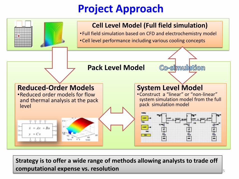
Project Approach Cell Level Model (Full field simulation)
•Full field simulation based on CFD and electrochemistry model •Cell level performance including various cooling concepts
System Level Model •Construct a “linear” or “non-linear” system simulation model from the full pack simulation model
Strategy is to offer a wide range of methods allowing analysts to trade off computational expense vs. resolution
Reduced-Order Models •Reduced order models for flow and thermal analysis at the pack level
Pack Level Model
5

ANSYS BATTERY DESIGN TOOL (ABDT)
Field Simulation (“Cell Level”)
System Simulation (“Pack Level”)
Reduced-Order Models (ROM)
Workbench Framework and UI
templates templates OAS files
Simplorer UI
Roadmap for Battery CAE Tools
ABDT is the “umbrella” over all capabilities, including the graphical user interface (UI) that automates/customizes battery simulation workflow, leveraging ANSYS commercial products. 6
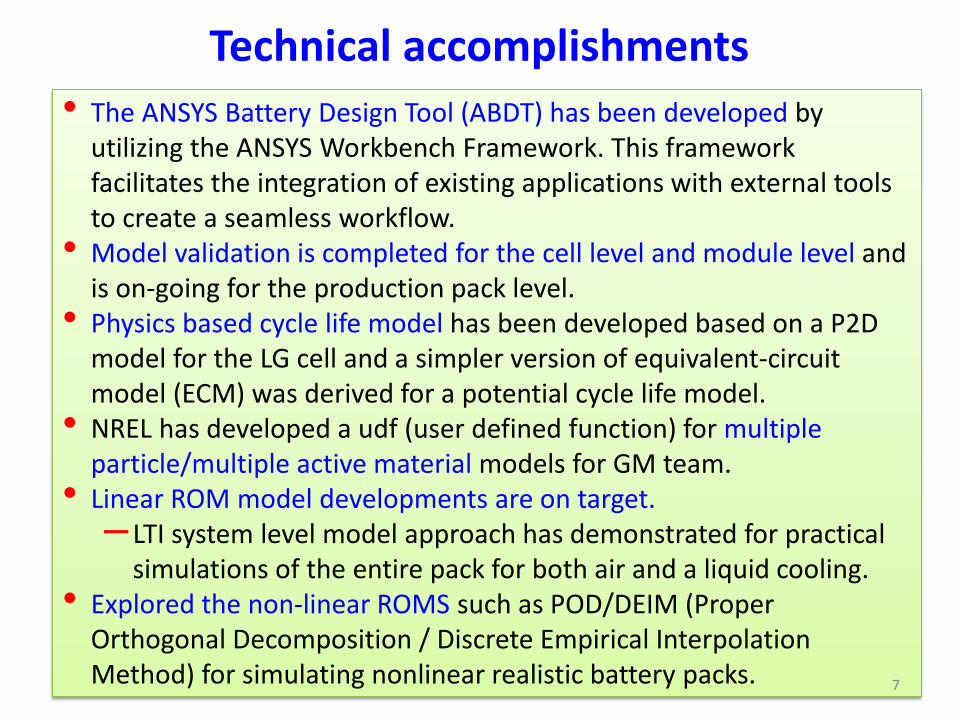
Technical accomplishments • The ANSYS Battery Design Tool (ABDT) has been developed by
utilizing the ANSYS Workbench Framework. This framework facilitates the integration of existing applications with external tools to create a seamless workflow.
• Model validation is completed for the cell level and module level and is on-going for the production pack level.
• Physics based cycle life model has been developed based on a P2D model for the LG cell and a simpler version of equivalent-circuit model (ECM) was derived for a potential cycle life model.
• NREL has developed a udf (user defined function) for multiple particle/multiple active material models for GM team.
• Linear ROM model developments are on target. – LTI system level model approach has demonstrated for practical
simulations of the entire pack for both air and a liquid cooling. • Explored the non-linear ROMS such as POD/DEIM (Proper
Orthogonal Decomposition / Discrete Empirical Interpolation Method) for simulating nonlinear realistic battery packs. 7
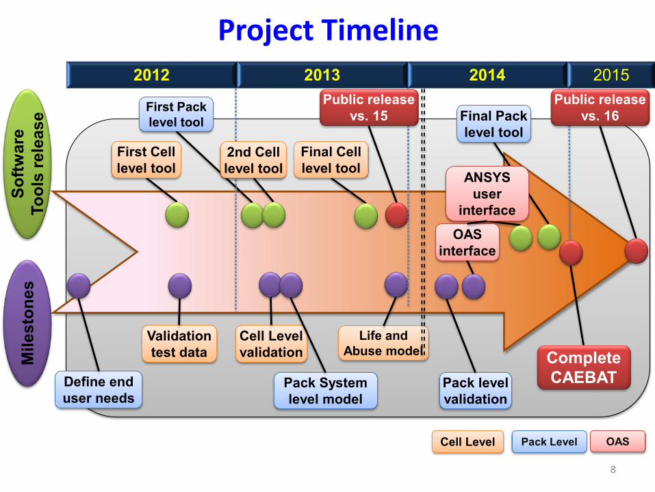
Pack Level Cell Level OAS
Project Timeline 2012 2013 2014 2015
8
First Cell level tool
Mile
ston
es
Softw
are
Tool
s re
leas
e
Final Cell level tool
First Pack level tool
Cell Level validation
Pack System level model
Life and Abuse model
ANSYS user
interface
OAS interface
Validation test data
Define end user needs
Pack level validation
2nd Cell level tool
Final Pack level tool
Public release vs. 15
Complete CAEBAT
Public release vs. 16

Full Field Simulation
Validation of CAEBAT Tools
Cell
Module
System Level Simulation
System model without ROM
Liquid Cooling
Cell/Module
Pack/Module
Completed for Cell and Module level
Completed for System model
On target
System model with ROM
9
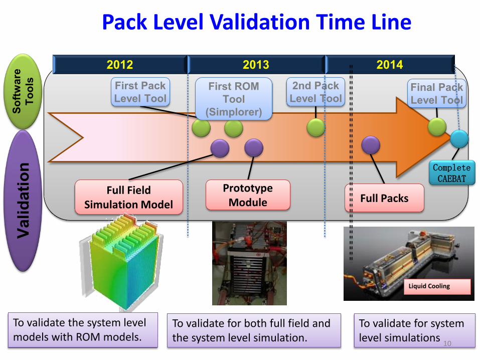
2012 2013 2014
Valid
atio
n So
ftwar
e To
ols First Pack
Level Tool First ROM
Tool (Simplorer)
Final Pack Level Tool
2nd Pack Level Tool
Complete CAEBAT
Full Field Simulation Model
Prototype Module
Liquid Cooling
To validate the system level models with ROM models.
To validate for both full field and the system level simulation.
To validate for system level simulations
Full Packs
Pack Level Validation Time Line
10
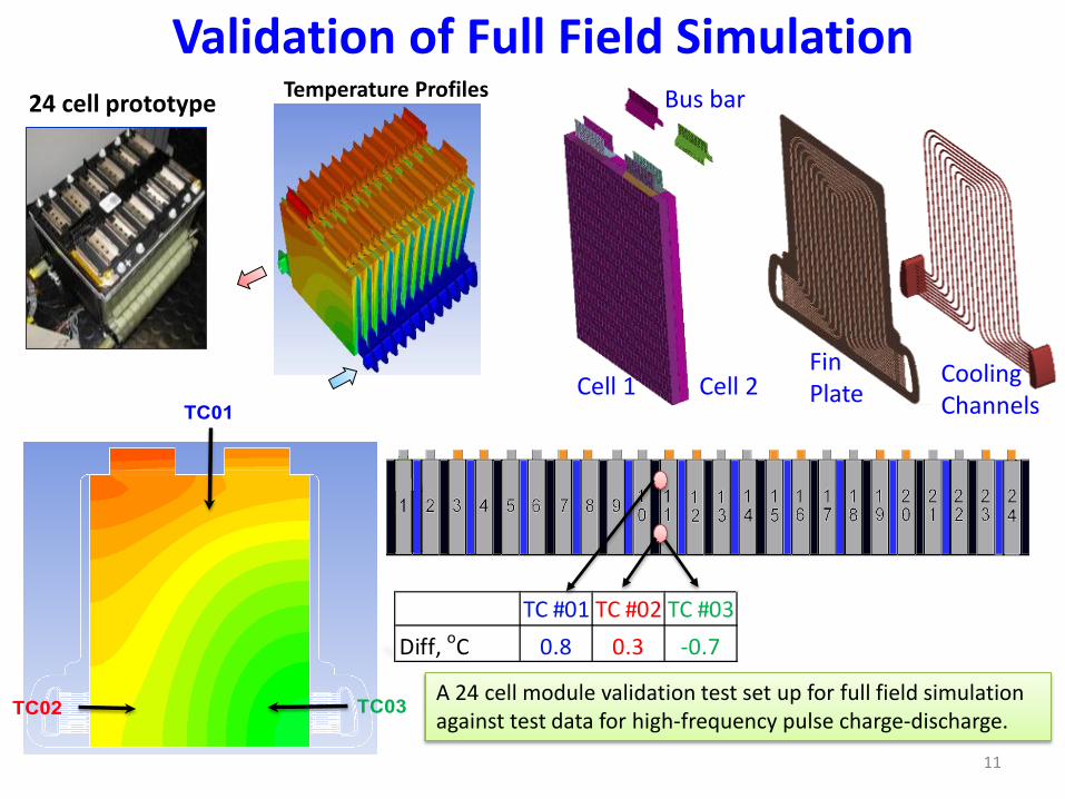
Temperature Profiles
Validation of Full Field Simulation
Cell 1 Cell 2
Bus bar
Fin Plate
Cooling Channels
24 cell prototype
A 24 cell module validation test set up for full field simulation against test data for high-frequency pulse charge-discharge.
11
TC01
TC02 TC03
TC #01 TC #02 TC #03Diff, oC 0.8 0.3 -0.7

Top View
Validation for 24 Cell Module
Measurement Prediction
No
data
No
data
Coolant
in Coolant
out
Maximum difference between the prediction and the measurement is within 1 OC. 12
Full Field Simulation

13
Unit
Module
Pack
Electric Circuit
System Simulation for 24 Cell Module
ABDT User Interface
Generate module and pack model
automatically
Thermal Circuit
14
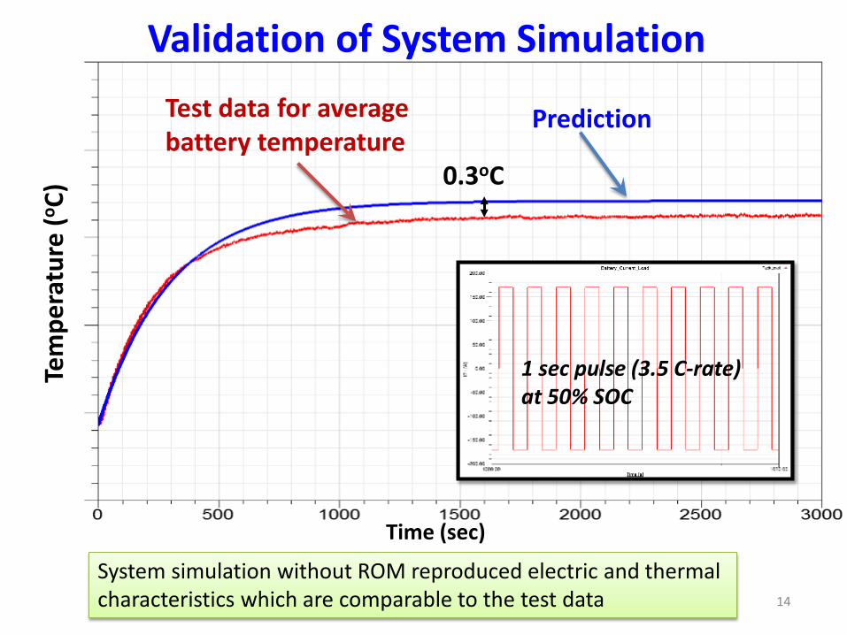
0.3oC
Tem
pera
ture
(o C)
Time (sec)
1 sec pulse (3.5 C-rate) at 50% SOC
Prediction Test data for average battery temperature
Validation of System Simulation
System simulation without ROM reproduced electric and thermal characteristics which are comparable to the test data

15
Validation of System Simulation for USO6 drive cycle
Time (sec)
0.5oC
Tem
pe
ratu
re (
oC
)
Prediction Test data for average battery temperature
Prediction Test data
Heat generation rate
10 W
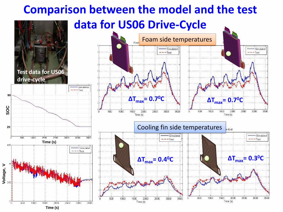
Test data for US06 drive-cycle

Battery Model
ROM Model
Current profile for USO6
HPPC Data ECM Fitting
SOC
Terminal Voltage
Heat Generation
Cell Temperature
USO6 drive cycle
hybrid pulse power characterization
LTI ROM System-Modeling approach for Battery Thermal Simulation
16
SO
C
Time (s)
90
20
Comparison between the model and the test data for US06 Drive-Cycle
17 Time (s)
Vo
ltag
e,
V
Test data for US06 drive-cycle
∆Tmax= 0.40C ∆Tmax= 0.30C
Cooling fin side temperatures
∆Tmax= 0.70C ∆Tmax= 0.70C
Foam side temperatures

• Develop flexible frame work for multi-physics models
• Integrate cell/pack level simulation capability
• Process automation & OAS
• Physics based cell aging model for capacity fade and cell life
Collaborations
• GM has interacted with all the team members, ANSYS, ESIM, ORNL, and NREL. • Last couple years we had weekly progress meetings with ANSYS, ESIM and NREL. • FY 2014, we has planned to have bi-weekly meetings to check the progress. • GM team has provided 4 Quarterly reviews each year to NREL and DOE.
•Provide project technical direction (Gi-Heon Kim, Tech monitor) •Provide Cell chemistry model for
multiple particle/active materials
•Open Architecture Software
• Perform math model verification and cell level validation
• Set vehicle requirements for cell and pack design • Perform vehicle level validation under various
driving schedules
• Collaborate with ANSYS/ESIM/NREL • Pack level strategy • ROM verification & validation • Pack level validation
• Perform test for cell level performance data and cycle life test

Future Work Remainder of FY14
— Thermal abuse/runaway model has been developed and will be implemented in the 2nd Q to handle the thermal propagation in the pack.
— Practical cell cycle life models have been defined and it is planned to be included in 3rd Q. The physics based cycle life model will be implemented 4th Q.
— Complete workflow automation for LTI/LPV ROM process. — Implement models for multiple active/particle materials. — Pack level verification, validation, and demonstration. — Complete battery-specific graphical user interface (ABDT) — Complete a standard data-exchange interface based on
specifications from the OAS Workgroup
19

• Several software deliverables for the cell level tools. – NREL’s MSMD framework is implemented in FLUENT with three electrochemistry sub-
models, 2Q 2013. – Cell level validation was completed, 3Q 2013. – Developed user defined electrochemistry models that allows user to apply their own
models while utilizing FLUENT’s battery framework, 4Q 2013. – The major release of FLUENT Version 15 in December 2013 contains NREL’s
MSMD battery model further developed jointly by GM and ANSYS. • First pack level software tool was delivered to GM, NREL, and ESim
– Auto electrical connection by detecting the cell configurations in the pack. – Code is completely parallelized, 2Q 2013.
• Cycle life test completed with 30% capacity fade. – Cycle life test at an elevated temperature is in progress and to be completed in 4Q 2014. – Physics based cycle life model has been developed and to be implemented in 4Q 2014.
• Pack level validation is completed for a 24 cell module. – Full field simulation was validated in 4Q 2013. – System level model was completed and validated compared to the full field simulation
and the test data and comparisons are satisfactory 1Q 2014. – LTI system level ROM model approach has been validated in comparison with the full
field simulation results 2Q 2013. – Demonstrated for USO6 driving cycles and validated in 4Q 2013 and 1Q 2014.
Summary
20

Sustainable Software Tool (CAEBAT)
•Modular: —Integrate physics and chemistry in a
computationally efficient manner. •Provide Flexibilities: —Provide a platform to enable various
simulation strategies. •Provide Expandable Framework: —Enable future users to easily add new
physics of interest. —OAS-compatible. •Validated : —Ensure model predictions agree with
experimental data by performing carefully designed experiments.
•Easy to use
Support of DOE CAEBAT The automotive industry requires CAE design tools that include the following capabilities.

Technical Back-Up Slides
22

23
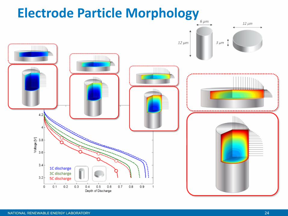
Why Multi-Particle Model?
Multiple Particle Model Uses
• Two-cathode and Two-anode cells are going into production vehicles• OCVs of two cathode materials, their diffusion mechanisms are different
causing highly nonlinear HPPC response that even 6P or 8P models were not able to capture
• Developing an equivalent single electrode is turning out to be a challenge for certain chemistries
• Diffusion coefficients and other time constants are functions of SOC, charge vs. discharge
• Physics-based degradation models for multiple particle models need to be developed – long term
• Battery cell manufacturers are interested in evaluating effect of particle size distribution (skewness, variance) on material utilization, performance (P/E ratio) using virtual methods – experimental techniques take years to assess
24
Electrode Particle Morphology

25
Implementation of NREL’s Multi-particle Model in ANSYS/Fluent using MSMD Protocol
• ANSNS: It will be a demonstration of expandability and flexibility of the model architecture that ANSYS/Fluent adopted in the project.
• GM: GM is interested in using the model with multiple particle, multiple active material features. GM CAE and Battery Algorithms teams are ready to apply these models.
• DOE/NREL: NREL’s developments can be quickly available to EV industries through CAEBAT program products.
• Public Benefit: This would be a good success story of delivering expertise in national lab to a direct use of EV industry using the DOE’s CAEBAT product outcomes.

Reformulation of Deshpande’s model • The model equations in original form
( ) ( ) ( ) ( ) ( )1
1/2 1/20 22SEI cr cr 0 th th
1
1 12 1 1 2 2 12 2
mNmmm
i
dQ BAL CN B l a K N BA C N i K N idN
ρ−
− −−−
=
= − − + − − − − ∑
cr crθ,max 0
mA l b a kρ σ π = ( )
s sθ,max
s
115 1
i REv FD
σ Ω
= − −
2SEI SEI s
1SEI 0
43600 s hr
n F RBM Q
ρ π−
= ⋅
22
θ,max 0 02
2
mmmC k b a aσ π
− − = −
[ ]02 1
s2
1
s
depth of a pre-existing crack m diffusion coefficient of the solute in the solid phase m s
Young's modulus of electrode material N m Faraday's constant C mol
aDEFi
−
−
−
⋅ ⋅
⋅
[ ][ ]
2
th
cr0SEI
SEI
current over electrode particle surface A m, Paris' law parameter
SEI thickness growth parameter depth of a pre-existing crack m
initial SEI thickness m m
k mKlLM
− ⋅
1olecular weight of compounds constituting SEI g mol− ⋅
[ ][ ]
SEI
0th
0
s
number of lithium atoms per SEI molecule formed capacity after formation cycle Ah capacity at N cycle Ah
fractional cell capacity radius of the spherical e
nQQQR [ ]
3SEI
2cr
2θ,max
lectrode particle m density of SEI film g m
number of cracks per unit area of the particle m maximum tangential stress N m
partial molar volum
ρρσ
−
−
−
⋅
⋅ Ω 3 1e of the solute m mol− ⋅
• The reformulated model equations ( ) ( ) ( ) ( )33
11/2 1/2
1 2 4 5 21
1 1N bb
i
dQ b b N b N b b N i N idN
− −− − −
=
= − − − − − − ∑0
1 SEI2b BAL= 2b C=3 2
mbm
=− 5 thb BAK=( )4 cr cr 0 th
11 22
b B l a Kρ= +where
The parameter vector is defined as [ ]1 2 3 4 5b b b b b=b
The capacity fade equation can be expressed as ( )f ,dQ NdN
= b
The parameter values in Deshpande’s model vary with materials and electrode designs; so a life model should involve the validation of the capacity fade equation
26
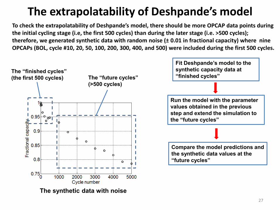
The extrapolatability of Deshpande’s model
The “finished cycles” (the first 500 cycles) The “future cycles”
(>500 cycles)
Fit Deshpande’s model to the synthetic capacity data at “finished cycles”
Run the model with the parameter values obtained in the previous step and extend the simulation to the “future cycles”
Compare the model predictions and the synthetic data values at the “future cycles”
The synthetic data with noise
To check the extrapolatability of Deshpande’s model, there should be more OPCAP data points during the initial cycling stage (i.e, the first 500 cycles) than during the later stage (i.e. >500 cycles); therefore, we generated synthetic data with random noise (± 0.01 in fractional capacity) where nine OPCAPs (BOL, cycle #10, 20, 50, 100, 200, 300, 400, and 500) were included during the first 500 cycles.
27

The Periodic HPPC measurements • Before each OPCAP check, the HPPC of the cell was measured. • In each HPPC, 9 pulses were made at different SOC, and the first 8
pulses were chosen to be used for model validation
The HPPC voltage profile
The 1st pulse
The 2nd pulse The 3rd pulse The 4th pulse The 5th pulse
The 6th pulse The 7th pulse
The 8th pulse
28

The 1st pulse The 2nd pulse The 3rd pulse
The 4th pulse The 5th pulse The 6th pulse
The 7th pulse The 8th pulse
Fitting ECM to HPPC at BOL
29

The 1st pulse The 2nd pulse The 3rd pulse
The 4th pulse The 5th pulse The 6th pulse
The 7th pulse The 8th pulse
Fitting ECM to HPPC at 1000th cycle
30

The 1st pulse The 2nd pulse The 3rd pulse
The 4th pulse The 5th pulse The 6th pulse
The 7th pulse The 8th pulse
Fitting ECM to HPPC at 2000th cycle
31

1. Taeyoung Han, Gi-Heon Kim, Lewis Collins, “Multiphysics simulation tools power the modeling of thermal management in advanced lithium-ion battery systems,” ANSYS Quarterly magazine "Advantage", 2012
2. Taeyoung Han, Gi-Heon Kim, Lewis Collins, “Development of Computer-Aided Design Tools for Automotive Batteries-CAEBAT,” Automotive Simulatiuon World Congress (ASWC), Detroit, October 2012.
3. Xiao Hu, Scott Stanton, Long Cai, Ralph E. White, “A linear time-invariant model for solid-phase diffusion in physics-based lithiumion cell models.,” Journal of Power Sources 214 (2012) 40-50.
4. Xiao Hu, Scott Stanton, Long Cai, Ralph E. White, “Model order reduction for solid-phase diffusion in physics-based lithium ion cell models,” Journal of Power Sources 218 (2012) 212-220.
5. Meng Guo, Ralph E. White, “A distributed thermal model for a Li-ion electrode plate pair,” Journal of Power Sources 221 (2013) 334-344.
6. Ralph E White, Meng Guo, Gi-Heon Kim, “A three-dimensional multi-physics model for a Li-ion battery”, Journal of Power Source, 2013.
7. Saeed Asgari, Xiao Hu, Michael Tsuk, Shailendra Kaushik, “Application of POD plus LTI ROM to Battery Thermal Modeling: SISO Case, to be presented in 2014 SAE World Congress.
8. Ramesh Rebba, Justin McDade, Shailendra Kaushik, Jasmine Wang, Taeyoung Han, ”Verification and Validation of Semi-Empirical Thermal Models for Lithium Ion Batteries ,” to be presented in 2014 SAE World Congress.
9. Meng Guo, Ralph E. White, “A distributed thermal model for a Li-ion electrode plate pair,” Journal of Power Sources 250 (2014) 220-235.
Publications/Presentations
32