development of beam-to-beam contact detection algorithms ... · development of beam-to-beam contact...
TRANSCRIPT

Development of beam-to-beam contact detection
algorithms for rotor-stator rubbing applications
Sebastien Roques, Mathias Legrand, Carlo Stoisser, Patrice Cartraud,
Christophe Pierre
To cite this version:
Sebastien Roques, Mathias Legrand, Carlo Stoisser, Patrice Cartraud, Christophe Pierre. De-velopment of beam-to-beam contact detection algorithms for rotor-stator rubbing applications.21st Biennal Conference on Mechanical Vibration and Noise ASME IDETC/CIE, Sep 2007,Las Vegas, United States. Proceedings of IDETC/CIE 2007 : 21st Biennial Conference onMechanical Vibration and Noise, <10.1115/DETC2007-34625>. <hal-01008067>
HAL Id: hal-01008067
https://hal.archives-ouvertes.fr/hal-01008067
Submitted on 29 Aug 2016
HAL is a multi-disciplinary open accessarchive for the deposit and dissemination of sci-entific research documents, whether they are pub-lished or not. The documents may come fromteaching and research institutions in France orabroad, or from public or private research centers.
L’archive ouverte pluridisciplinaire HAL, estdestinee au depot et a la diffusion de documentsscientifiques de niveau recherche, publies ou non,emanant des etablissements d’enseignement et derecherche francais ou etrangers, des laboratoirespublics ou prives.

Distributed under a Creative Commons Attribution 4.0 International License

Proceedings of IDETC/CIE 200721st Biennial Conference on Mechanical Vibration and Noise
September 4-7, 2007, Las Vegas, Nevada, USA
DETC2007-34625
DEVELOPMENT OF BEAM-TO-BEAM CONTACT DETECTION ALGORITHMS FORROTOR-STATOR RUBBING APPLICATIONS
Sebastien RoquesGeM, Pole Calculs et Structures
Ecole Centrale Nantes44000 Nantes, France
Email: [email protected]
Mathias LegrandMcGill University
McDonald Engineering BuildingMontreal H3A 2K6, Canada
Email: [email protected]
Carlo Maria StoisserEDF Research & Development
Acoustics and Mechanical Analysis92141 Clamart, France
Email: [email protected]
Patrice CartraudGeM, Pole Calculs et Structures
Ecole Centrale Nantes44000 Nantes, France
Email: [email protected]
Christophe PierreMcGill University
McDonald Engineering BuildingMontreal H3A 2K6, Canada
Email: [email protected]
ABSTRACT
In nuclear power plant turbosets, the design-basis accidentconsists of a blade-off on the low pressure turbine last stage. Dur-ing the accidental shutdown, a severe rotor-casing interactionmay occur at critical speeds due to large shaft line displacementsoriginated by a high unbalance excitation. The contact betweenthe shaft and the stator, also called the diaphragm in this study,induces an important angular deceleration rate and greatly mod-ifies the turbogenerator dynamics including the amplitude of theloads in the bearings. Therefore the main objective is to ver-ify that the designed turbine is capable of going through criticalspeeds without catastrophic consequences for the shaft line. Tothis end, a model of a turbogenerator has been developed to com-pute rotor speed transients by considering the rotating speed ofthe rotor as an unknown, which allows for the angular deceler-ation due to rubbing to be calculated in a more realistic fash-ion. Lagrange multipliers method is applied to compute contactforces. The diaphragm, which is a non-rotating bladed disks as-sembly, is modeled by curved and straight beams, and differentassumptions for the contact detection are studied to find a com-promise between CPU time and accuracy. Results of the numeri-cal tool show that the contact forces are sensitive to the retainedassumptions only when heavy rub occurs. Nevertheless, the ro-tating speed and bearing loads are computed with a satisfactoryaccuracy, even with an approximation on contact detection thatsaves CPU time.
INTRODUCTIONIn turbomachinery, contact between rotating and stationary
parts of the turbine, usually referred to as rub [1, 2], is known tobe a serious malfunction. Rub is usually caused by unbalancedrotor, blade-off, misalignment of the rotor centerline, thermal un-balance, casing excitations, to name a few. In this study, theshaft-diaphragm interaction only is considered: indeed, in realturbosets, the blades-to-diaphragm contact [3] is negligible incomparison to the shaft-stator interaction to compute the angu-lar deceleration due to friction and the torsional stresses in thecoupling components. For a detailed overview of rubbing phe-nomena and its associated literature, the reader is referred to thevery thorough survey given by Muszynska [4].
During the past decades, numerous authors have developedand enhanced mathematical models characterizing the rotor-stator interaction. First mathematical models are the Jeffcottrotors [5] with the following assumptions: linear stiffness anddamping, rigid disk on a massless shaft, Coulomb law as frictionmodeling, stator modeled by springs acting in the radial directionand sometimes with dampers. Moreover, due to its simplicity inprogramming, the penalty method is often used to compute con-tact forces. Then, with modern computers, the behavior of flex-ible rotors has been studied by finite element approach and/ormodal synthesis techniques [6] allowing more realistic models.However these studies were limited to steady state analysis sothat the angular velocity remains constant, which implies an in-
1

crease of the driven motor torque in the case of rub. The equa-tions of motion have been rewritten considering that the speedlaw is given in order to compute rotor speed transient [6]. Any-way, the main limitation of these simulations lies in the fact thatthe angular deceleration which is originated by contact betweenthe shaft line and the stator is not taken into account. To theauthors’ knowledge, only Dai [7] has investigated a rigid rotormodel where an additional equation computes the instantaneousrotating speed depending on the contact forces. This model canreproduce the rotor response with partial as well as full annularrubbing. Finally, other works included the coupling between lat-eral and torsional vibrations for a steady state. Edwards et al [8]concluded that the torsional phenomenon should be included inrubbing modeling.
Therefore, the primary goal of the present paper is to give abetter representation of the rotor-stator interaction during speedtransients. To this end, a numerical tool [9] has been developed tocompute the transient dynamical response of the shaft line withshaft-to-stator contact. In this model, the rotating speed of therotor is considered as an unknown, which allows for the angulardeceleration due to rubbing to be calculated in a more realisticfashion. In conjunction with the Lagrange multipliers approachwhere friction is considered, the governing equations of the cou-pled rotor-stator system are solved using a time-stepping proce-dure based on the explicit central differences scheme [10].
The paper is organized as follows. The first section presentsthe modeling of the two structures used in the numerical tool.The contact dynamics is investigated in the second section whereassumptions are used during the contact detection. Finally, thedifferent time integration results corresponding are compared.
1 STRUCTURAL MODELSIn this section, the FE modeling of the two structures and
the general algorithm to solve speed transients are presented.
SHAFT LINEA 1-D turbine system is built by modeling the shaft with
straight spinning Timoshenko beams, bladed disks with circularrigid disk and imbalances with concentrated masses. An aca-demic example is depicted in figure 1. The originality of the
1
3 47
9
diaphragm
disk
unbalancebearing
Figure 1. SCHEMATIC OF THE ROTOR MODEL
modeling lies in the fact that the angular position is consideredas an unknown of the problem. Gyroscopic effects are taken intoaccount which couple the torsional vibrations and the lateral ones.More details concerning the model are given in [9].
�!x
�!y
�!z
u
v
w
�!X�!
X
�!Y
�!Y
�!Z
�!Z
�!x1
�!y1
�!z1
�!x2
�!y2
'
'
ˇ
ˇ
�u�u
�v
�v
Figure 2. NOTATIONS FOR A DISK
Rigid disk The kinetic energy EDc of an axi-symmetric rigid
circular disk rotating at an angular speed P' takes the form:
2EDc D MD
� Pu2 C Pv2 C Pw2�CIDX
h P�2u cos2 �v C P�2
v
iCIDZ
�P�2u sin2 �v C
�P' C P�2 C2
�P' C P� P�u sin�v
�(1)
where MD , IDX and IDZ respectively stand for the mass, thesecond moment of inertia and the polar moment of inertia of thedisk. Referring to figure 2, .u;�v/ denotes the bending displace-ments in the .X;Z/ plane, .v;�u/ the bending displacements inthe .Y;Z/ plane, w the traction along Z axis and ˇ, the torsion inZ direction. The derivative of x with respect to time is denotedPx. Within the small perturbation framework, the kinetic energyis rewritten as follows:
2EDc D MD
� Pu2 C Pv2 C Pw2� CIDX
h P�2u C P�2
v
iCIDZ
��P' C P�2 C2
�P' C P� P�u�v
�(2)
Equation (2) must be exact up to the third order so that all secondorder terms are retained in equations of motion. It is worth notingthat the axial vibrations only are independent.
2
Shaft The kinetic energy Ec of the shaft corresponds to theintegration of the disk energy along its longitudinal direction:
2Ec D �
Z l
0
"S
� Pu2 C Pv2 C Pw2CIx
� P�2u C P�2
v
�
CIp
�P' C P�2 C2
�P' C P� P�u�v
�#dz (3)
where �, S , Ix and Ip respectively refer to the mass density, thecross-section area, the moment of inertia and the polar momentof inertia of the beam. The potential energy Ed of a spinningTimoshenko beam is given by the following integral:
2Ed DZ l
0
"ESw2
;z CEIx
��2
u;z C�2v;z
CGIpˇ2;z C
CkGSh.u;z � �v/2 C .v;z C�u/2
i#dz (4)
where E , G and k respectively stand for Young’s, shear moduliand the transverse shear form factor.
Bearings In real turbines, oil film bearings are used to supportthe shaft. The dynamical study of a shaft line requires to describethe nonlinear behavior of the oil film. As a first approach, stiff-ness and damping coefficients of the oil film are approximatedby linearizing Reynolds’ equations with respect to the equilib-rium position. Moreover a comparison of results between linearand nonlinear modelings [11] has shown that the behavior of thecrushed oil film, when passing through critical speeds, can beaccurately approximated by a very stiff bearing.
The equations of motion derived from Hamilton’s principleare nonlinear even without considering any contact.
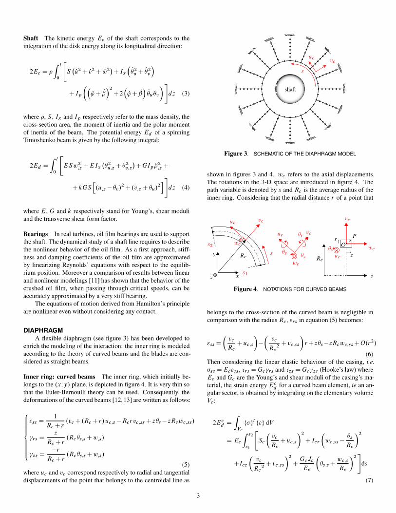
DIAPHRAGMA flexible diaphragm (see figure 3) has been developed to
enrich the modeling of the interaction: the inner ring is modeledaccording to the theory of curved beams and the blades are con-sidered as straight beams.
Inner ring: curved beams The inner ring, which initially be-longs to the .x;y/ plane, is depicted in figure 4. It is very thin sothat the Euler-Bernoulli theory can be used. Consequently, thedeformations of the curved beams [12,13] are written as follows:
8ˆ<ˆ:
"ss D 1
Rc C r.vc C .Rc C r/uc;s � Rcrvc;ss C z�s � zRcwc;ss/
�rs D z
Rc C r.Rc�s;s Cw;s/
�zs D �r
Rc C r.Rc�s;s Cw;s/
(5)where uc and vc correspond respectively to radial and tangentialdisplacements of the point that belongs to the centroidal line as
shaft
s
uc vc
Figure 3. SCHEMATIC OF THE DIAPHRAGM MODEL
shown in figures 3 and 4. wc refers to the axial displacements.The rotations in the 3-D space are introduced in figure 4. Thepath variable is denoted by s and Rc is the average radius of theinner ring. Considering that the radial distance r of a point that
RcRc
G
Pr
z
z
z x
y s
s1
s2
uc
uc
ucvc
vc
vc
wc
wc
wc�s
�s
�r
�z
Figure 4. NOTATIONS FOR CURVED BEAMS
belongs to the cross-section of the curved beam is negligible incomparison with the radius Rc , "ss in equation (5) becomes:
"ss D
vc
Rc
Cuc;s
��
vc
Rc2
Cvc;ss
�r Cz�s �zRcwc;ss CO.r2/
(6)Then considering the linear elastic behaviour of the casing, i.e.�ss D Ec"ss, �rs D Gc�rs and �zs D Gc�zs (Hooke’s law) whereEc and Gc are the Young’s and shear moduli of the casing’s ma-terial, the strain energy Ec
dfor a curved beam element, ie an an-
gular sector, is obtained by integrating on the elementary volumeVc:
2Ecd D
ZVc
f�gt f"g dV
D Ec
Z s2
s1
"Sc
vc
Rc
Cuc;s
�2
CIcr
wc;ss � �s
Rc
�2
CIcz
vc
Rc2
Cvc;ss
�2
C GcJc
Ec
�s;s C wc;s
Rc
�2#
ds
(7)
3

suc
vc
wc
�s �r
x
�!xg
�!yg
ub
vb
wb
�ub
�vb
�wb
Figure 5. NOTATIONS FOR BLADES
where Icr , Icz, Jc and Sc respectively stand for the two momentsof inertia, the polar moment of inertia and the cross-section areaof the curved beam. The kinetic energy is equal to:
2Ecc D �c
Z s2
s1
"Sc
� Pu 2c C Pv 2
c C Pw 2c
CIcr Pw 2c;sC
Icz
Puc
Rc
� Pvc;s
�2
CIcpP�s
2
#ds (8)
with Icp denoting the moment of inertia.
Blades: straight beams The Euler-Bernoulli theory is alsoused for the blades which are slender structures. Their energiescorrespond to a particular case of equations 3 and 4: the angularspeed is equal to zero and since Euler-Bernoulli theory is consid-ered, the shear energy vanishes and the two usual kinematic rela-tionships are used. Then, according to the notations introducedin figure 5, it comes:
8ˆ<ˆ:
2Ebc D �
Z l
0
hSb
� Pu 2b C Pv 2
b C Pw 2b
CI bz
P� 2wb
CI by
P� 2vb
CI bx
P� 2ub
idx
2Ebd D
Z l
0
hESbu 2
b;x CEI bz
P� 2wb ;x CEI b
yP� 2vb ;x CGJ b P� 2
ub ;x
idx
�wbD vb;x et �vb
D �wb;x
where I bz , I b
y , I bx , J b and Sc respectively stand for the two sec-
ond moments of inertia, the polar moment of inertia, the cross-sectional polar moment of inertia and the cross-section area ofthe rectangular straight beam.
A proper modeling of the connection between the curvedbeam elements and the straight beam elements is required. It isachieved through the following relationships coming from Euler-
Bernoulli assumptions of curved beams:
�wbD �z D uc
Rc
� vc;s et �ubD �r D wc;s (9)
Equations of motions are derived in a very general fashion fora 3-D space but, in what follows, the diaphragm is representedby a planar model for the sake of simplicity. Equivalently, theconditions wc D 0 and �s D 0 are considered.
2 CONTACT DETECTIONThe forces of particular interest in this study are the contact
forces acting between the shaft and the diaphragm where frictionis considered. The following assumption for the contact detec-tion is used: only one point of the rotor cross-section, which issupposed rigid, comes into contact with the diaphragm.
General theoryTo describe the contact dynamics, the master-slave approach
is used. Then, for any point of coordinates x belonging to themaster interface, the gap function g.x/ between the two bodiescan be stated as follows:
g.x/ D g0.x/ C�u.m/.x/ � u.s/.Nx/
�� n.m/
where g0 denotes the initial gap, n.m/ the unit vector tangentto the surface of the master body (ie outward pointing normal),u.m/.x/ and u.s/.Nx/ respectively the displacement of the pointthat belongs to the master interface and the one of the point ofthe slave surface whose coordinates Nx minimizes the interpene-tration.
When the Lagrange multipliers method is used, the contactconditions [14] can be seen as the Kuhn-Tucker optimality condi-tions [15]: all material point x that belongs to the master interfacemust satisfy the following equation:
�N � 0, g.x/ � 0 and �N g.x/ D 0
where �N stands for the positive contact force acting on the slavesurface in the normal direction. The gap function must be posi-tive because two bodies cannot interpenetrate: this is also knownas the impenetrability condition. To these unilateral contact con-ditions, the Coulomb friction law is added when only sliding oc-curs:
j�T j D �j�N j ) 9a so that vT D a�T
j�T j
for which � is the coefficient of friction, vT the tangential slipvelocity and �T , the contact force acting on the tangential direc-tion.
4

Application to rotor-stator systemIn this study, the master body is the rotor and the slave the
stator. Then the coordinates Nx of the casing must be determined.However, as the nonlinear detection of contact greatly increasesthe CPU time, different assumptions are made:
1. contact approximation (Hyp 1): the contact location on thecasing (point C1 in figure 6) has the same angular positionas the rotor geometric center;
2. exact contact (Hyp 2): Nx, referred as point C2 in figure 6, iscomputed by minimizing the gap function g.x/ which is an-alytically calculated for any material point of the diaphragmby considering the exact deformed shape of the stator.
Once the contact location is obtained, the gap function is lin-earized to construct the contact constraint matrix in the normaldirection. The contact constraint matrix in the tangential direc-tion is calculated by considering that only sliding occurs [3]. The
Initial configuration
Deformed configuration
O
R
C1C2
gap
�!X
�!Y
�!�T
�!�N
�!�N
Cf ric
Figure 6. CONTACT DETECTION
radial contact force component �N is computed by using the La-grange multipliers method, which guarantees the impenetrabilitycondition. The tangential contact force �T , which is acting oppo-site to the direction of the relative sliding velocity, stems from theCoulomb friction law with an amplitude equal to j�T j D �j�N j.Finally, the friction torque takes the form Cf ric D �RFN .
3 GENERAL ALGORITHMTo the author’s knowledge, the forward increment Lagrange
method [10] gives satisfactory results for such contact-impactproblems [3]. Consequently this method is used in our study:a finite central differences scheme combined with Lagrangemultipliers (prediction-correction algorithm) properly satisfiesthe contact detection and ensures the compatibility of the speedand the acceleration.
Therefore, equations of motion are discretized in time ac-cording to central finite differences:
Pa ' anC1 � an�1
2tand Ra D anC1 � 2an Can�1
t2
with a D X or '. Xn refers to the generalized displacements X
in which bending, traction and torsion are stored at time tn andt to the time step.
Since the system of equations is non-linear, a specific timeprocedure is developed in algorithm 1. As the aim of this studyis to compute the response of a low pressure turbine in abnormalconditions, the initial and boundary conditions are given as fol-lows: operating at normal conditions, the turbine is suddenly dis-connected after the blade-off. Simultaneously, only aerodynami-cal and Newtonian fluid friction slow down the shaft line [16].
Initialization of X and ' for t0 and t1For n from 2 to nend do
Prediction of (XnC1, 'nC1)Iteration to solve the nonlinear governing equationsWhile (k Residual vector of equations k2 � ") do
If (No penetration) then�N D 0
elseComputation of Lagrange multipliersCorrection with contact forces (in the nor-mal direction �N and in the tangentialone �T D ��N ) and the resisting torquedue to friction Cf ric D �R�N
end IfNew guess .XnC1;'nC1/
doneIf ('nC1 < 'n) then
breakend IfResults are recordedNext time step increment
end For
ALGORITHM 1: TIME INTEGRATION PROCEDURE
Since the exact contact detection requires to update the con-tact location at each iteration of the nonlinear solver, the CPUtime prohibitively increases. Therefore, in order to find a com-promise between CPU time and accuracy, the contact locationcan be chosen to remain the one obtained during the predictionstep (no update in the iterative process).
4 RESULTSThe shaft line mode used for simulations is depicted in fig-
ure 1. The initial gap between the shaft and the diaphragm isequal to 8mm. Convergence of results with respect to the timestep and satisfaction of the impenetrability condition have beenshown in [9].
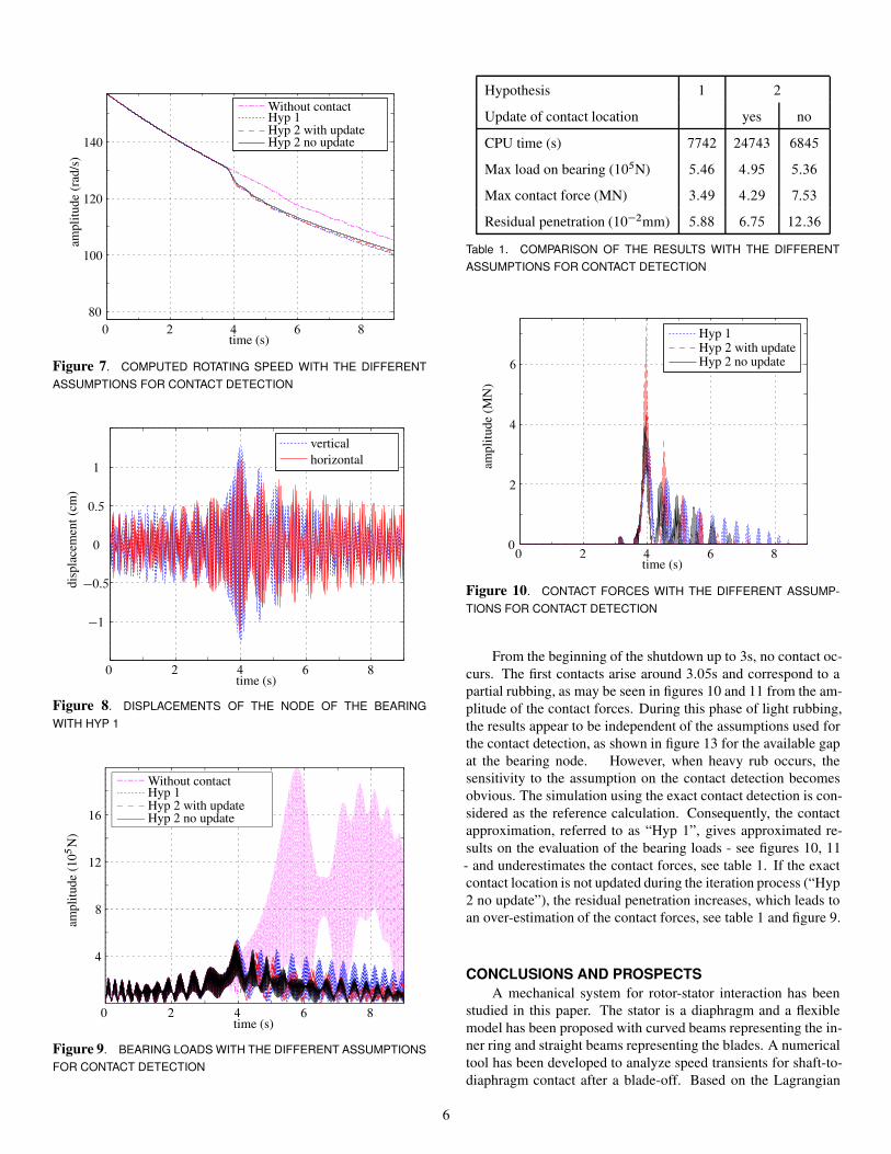
The sensitivity to the proposed assumptions for the contactdetection is now studied: the computed rotating speed and the dis-placements at the bearing location are depicted in figure 7 and 8.Table 1 summarizes the main results.
5
time (s)
ampl
itude
(rad
/s)
Without contactHyp 1Hyp 2 with updateHyp 2 no update
0 2 4 6 8
80
100
120
140
Figure 7. COMPUTED ROTATING SPEED WITH THE DIFFERENTASSUMPTIONS FOR CONTACT DETECTION
disp
lace
men
t(cm
)
time (s)
verticalhorizontal
0 2 4 6 8
�1
�0:5
0
0:5
1
Figure 8. DISPLACEMENTS OF THE NODE OF THE BEARINGWITH HYP 1
time (s)
ampl
itude
(10
5N
)
Without contactHyp 1Hyp 2 with updateHyp 2 no update
0 2 4 6 8
4
8
12
16
Figure 9. BEARING LOADS WITH THE DIFFERENT ASSUMPTIONSFOR CONTACT DETECTION
Hypothesis 1 2
Update of contact location yes no
CPU time (s) 7742 24743 6845
Max load on bearing (105N) 5:46 4:95 5:36
Max contact force (MN) 3:49 4:29 7:53
Residual penetration (10�2mm) 5:88 6:75 12:36
Table 1. COMPARISON OF THE RESULTS WITH THE DIFFERENTASSUMPTIONS FOR CONTACT DETECTION
time (s)
ampl
itude
(MN
)
Hyp 1Hyp 2 with updateHyp 2 no update
0 2 4 6 80
2
4
6
Figure 10. CONTACT FORCES WITH THE DIFFERENT ASSUMP-TIONS FOR CONTACT DETECTION
From the beginning of the shutdown up to 3s, no contact oc-curs. The first contacts arise around 3:05s and correspond to apartial rubbing, as may be seen in figures 10 and 11 from the am-plitude of the contact forces. During this phase of light rubbing,the results appear to be independent of the assumptions used forthe contact detection, as shown in figure 13 for the available gapat the bearing node. However, when heavy rub occurs, thesensitivity to the assumption on the contact detection becomesobvious. The simulation using the exact contact detection is con-sidered as the reference calculation. Consequently, the contactapproximation, referred to as “Hyp 1”, gives approximated re-sults on the evaluation of the bearing loads - see figures 10, 11- and underestimates the contact forces, see table 1. If the exactcontact location is not updated during the iteration process (“Hyp2 no update”), the residual penetration increases, which leads toan over-estimation of the contact forces, see table 1 and figure 9.
CONCLUSIONS AND PROSPECTSA mechanical system for rotor-stator interaction has been
studied in this paper. The stator is a diaphragm and a flexiblemodel has been proposed with curved beams representing the in-ner ring and straight beams representing the blades. A numericaltool has been developed to analyze speed transients for shaft-to-diaphragm contact after a blade-off. Based on the Lagrangian
6

time (s)
ampl
itude
(MN
)
Hyp 1Hyp 2 with updateHyp 2 no update
3 3:2 3:4 3:6 3:80
0:4
0:8
1:2
1:6
2
Figure 11. CONTACT FORCES AT FIRST IMPACTS WITH THE DIF-FERENT ASSUMPTIONS FOR CONTACT DETECTION
time (s)
ampl
itude
(mm
)
Hyp 1Hyp 2 with updateHyp 2 no update
0 2 4 6 8
0
2
4
6
8
Figure 12. GAP FUNCTION WITH THE DIFFERENT ASSUMPTIONSFOR CONTACT DETECTION
time (s)
ampl
itude
(mm
)
Hyp 1Hyp 2 with updateHyp 2 no update
3 3:5 4 4:5
0
2
4
6
Figure 13. GAP FUNCTION DURING FIRST IMPACTS WITH THEDIFFERENT ASSUMPTIONS FOR CONTACT DETECTION
multiplier method, different algorithms have been studied forthe contact implementation in order to optimize the computationtime.
In the case of partial rub, simulations have shown that resultsdo not depend on the assumption made on the quality of the con-tact detection. However, since this study focuses on accidentalshutdowns, full annular rubbing may occur. Results have shownthat, when heavy rub occurs, the contact forces are then sensitiveto simplifying assumptions for the contact detection. Nonethe-less all these assumptions may be used to obtain other quantitiesof interest such as rotating speed or bearing loads with a goodaccuracy and saving CPU time.
Experiments on a test rig devoted to rubbing will be per-formed in the next future in order to validate this rotor-stator in-teraction modeling. The time integration results will be analyzedby means of the time-frequency tools. Finally, the diaphragmmodel will be extended by adding axial deformations and workis in progress to take into account the beam-to-beam contact in3-D space.
ACKNOWLEDGMENTThis research was carried out for Electricite De France. The
authors gratefully acknowledge EDF R&D for its support.
REFERENCES[1] Muszynska, A., Bently, D., Franklin, W., Hayashida, R.,
Kingsley, L., and Curry, A., 1989. Influence of rubbing onrotordynamics - part i & ii. Tech. rep., NASA Contract NNAS8-36179.
[2] Muszynska, A., 2005. Rotordynamics. Taylor & Francis.[3] Legrand, M., 2005. “Modeles de prediction de l’interaction
rotor/stator dans un moteur d’avion”. PhD thesis, EcoleCentrale Nantes.
[4] Muszynska, A., 1989. “Rotor-to-stationary element rub-related vibration phenomena in rotating machinery - liter-ature survey.”. The Shock and Vibration Digest, 21, pp. 3–11.
[5] Pavlovskaia, E., Karpenko, E., and Wiercigroch, M., 2004.“Non-linear dynamic interactionsof a jeffcott rotor withpreloaded snubber ring”. Journal of Sound and Vibration,276, pp. 361–379.
[6] Lalanne, M., and Ferraris, G., 1998. Rotordynamics Predic-tion in Engineering. John Wiley.
[7] X. Dai, Z. J., and Zhang, X., 2002. “Dynamic behaviorof the full rotor/stop rubbing : numerical simulation andexperimental verification”. Journal of Sound and Vibration,251, pp. 807–822.
[8] Edwards, S., Lees, A., and Friswell, M., 1999. “The influ-ence of torsion on rotor/stator contact in rotating machin-ery”. Journal of Sound and Vibration, 225, pp. 767–778.
[9] Roques, S., Stoisser, C., Cartraud, P., Legrand, M., Pierre,C., and Peseux., B., 2006. “Modeling of rotor speed tran-sient with rotor-to-stator contact”. In 7th IFToMM – Con-ference on Rotor Dynamics, Vienna, Austria.
[10] Taylor, R., Carpenter, N., and Katona, M., 1991. “La-grange constraints for transcient finite element surface con-
7

tact”. Int. Journal for Numerical Methods in Engineering,32, pp. 103–128.
[11] Audebert, S., Clement, J.-C., and Stoisser, C., 2006. “Dy-namical behaviour of a turbogenerator set in accidental con-ditions: about a simplified method for the determination ofmaximal bearing loads”. In 7th IFToMM – Conference onRotor Dynamics, Vienna, Austria.
[12] Peseux, B., 1989. “Contribution a l’etude des structures par-tiellement ou totalement immergees en materiau homogeneou composite”. These de doctorat d’etat es sciences, EcoleNationale Superieure de Mecanique, Nantes, France.
[13] Dubigeon, S., 1998. Mecanique des Milieux Continus.Lavoisier, Tec & Doc, Nantes.
[14] Belytschko, T., Liu, W. K., and Moran, B., 2000. NonlinearFinite Elements for Continua and Structures. John Wileyand Sons, Ltd., New York.
[15] Minoux, M., 1983. Programmation mathematique -Theorie et algorithmes, Tome 1. Dunod Ed.
[16] Fortin, T., 1993. “Modelisation de ralentissement de GTA”.Rapport interne EDF R&D – HP-65/93/189.
8