development of a programmable logic controller … of a programmable logic controller experiential...
TRANSCRIPT

Development of a Programmable Logic Controller Experiential Learning Platform
Richard B. Mindek, Jr.
Western New England College, Springfield Massachusetts Abstract An experiential learning platform was recently developed to expose graduate engineering students, as well as undergraduate junior and senior mechanical engineering students, to the concept, components, operation, and application of programmable logic controllers (PLCs). The platform consists of a programmable logic controller, which can be programmed with a desktop PC, in order to control several simple output devices. The system allows students to write their own ladder logic programs, and to experiment with the program structure needed to control particular output devices. Student feedback to date suggests the availability of this platform, which encourages self-exploration, has had a very positive impact on student learning in a recently run graduate course. Plans for implementing an experiential learning approach using an updated version of the same platform in the undergraduate engineering curriculum are also discussed. 1.0 Introduction A programmable logic controller (PLC) is a microprocessor-based control system used by industry to communicate with other process control components. It is used in process control for simple switching tasks, proportional-integral-derivative (PID) control, complex data manipulation, arithmetic operations, timing and process and machine control and coordination. Groover [1] defines a PLC as: “A microcomputer-based controller that uses stored instructions in programmable memory to implement logic, sequencing, timing, counting, and arithmetic functions, using digital and analog input/output (I/O) modules, for controlling machines and processes.” Although PLC’s are used in the process industries (e.g., processing mined materials and oil refineries), they are more commonly found in discrete manufacturing industries, such as in machine control, transfer lines, and material handling equipment. First conceived in 1968 by Richard Morley, the PLC was originally developed as a device to overcome the inflexibility and high cost of hard-wired controllers made of relays, coils, counters, timers, and similar mechanical components. GM Corporation subsequently developed a set of specifications, which included that the PLC be: (1) programmable and reprogrammable; (2) capable of being used in a rugged (industrial) environment; (3) able to accept 120 VAC I/O; (4) have output capability needed to continuously run devices (motors, relays, etc.) of a 2A rating; and (5) competitively priced relative to mechanical devices. As technology has advanced over the years, especially microprocessor technology, PLC capability has grown from primarily on/off control to include operator interfaces, performing arithmetic operations and data manipulation, computer communications, supplemental computer memory, analog and positioning control, and remote I/O. Today, PLC’s are used in all facets of industry, provide a broad range of functions, can be programmed using a desktop personal computer, and can be purchased for as little as several hundred dollars. With such broad use in industry, wide-ranging application in engineering related fields and availability to users at all levels, it is imperative that engineering educators provide young engineers with a fundamental understanding of the operation and capabilities of PLCs. This task has recently been undertaken within the Mechanical Engineering Program at Western New England College, through the building of a PLC platform and development of a PLC laboratory. This laboratory is unique in that it is designed to allow students to self-learn fundamental PLC operation. The purpose of this paper to describe the work recently completed in this area at Western New England College, report on the use of the platform at the graduate level, as well as present future plans to incorporate it within the undergraduate engineering curriculum.

2
2.0 Basic Components of the PLC Platform In order to give students an opportunity to experience how computer automation and control is accomplished in a manufacturing environment, a demonstration apparatus was built containing actuation and sensing devices, a computer interface, feedback control, and an Allen Bradley MicroLogix 1500 programmable logic controller. This platform can be utilized by the instructor in a classroom environment for demonstration purposes, as well as by students as part of an active learning environment within or outside of the classroom. The apparatus is flexible so as to allow students to investigate how a basic control system works to perform an automated task, including the basics of how the various components of the system function and communicate with each other, and to investigate the theory associated with proportional, integral, derivative control and associated techniques. Figure 1 is a photograph of the basic PLC system used in this laboratory. It consists of a personal computer, which is loaded with both RSLinx and RSLogix 500 software, used for PLC communication and programming the PLC, an Allen Bradley MicroLogix 1500 PLC, and a series of relays, switches and power sources, which are used as representative I/O components that a typical PLC would control. A description of each of the components of the system follows.
Figure 1 – PLC System Used in this Laboratory Figure 2 – PLC System Components Personal Computer and Software: The personal computer used in this laboratory (see Figure 1) is a Dell computer, with Pentium III processor operating at a speed of 996 MHz, and 256 MB RAM. It is equipped with a CD ROM drive (not writeable), a zip drive (100 MB) and a floppy disk drive. The computer is loaded with a Windows XP operating system. Other software loaded on the PC to support this laboratory includes both RSLinx, rev. 2.43 and RSLogix 500, ver. 6.30, written for Rockwell Automation, Inc. networks and devices. The purpose of RSLinx software is to provide communication between the programmable controller and the PC. RSLogix 500 software is the application software used in the laboratory in conjunction with the MicroLogix 1500 PLC. This software allows the user to configure the PLC and to upload and download control programs, more commonly known as ladder logic programs [2]. Programmable Logic Controller: The PLC used in this laboratory is an Allen Bradley MicroLogix 1500, 1764-24BWA. It contains a base unit with a power supply, input and output circuits, and a 1764-LRP Series C processor. It has a line power of 120/240 VAC, 8 standard 24 VDC inputs, 4 fast 24 VDC inputs, 12 relay outputs, 2 isolated relays per unit, and 4 high speed I/O (20 kHz) [3]. I/O Components: Several inputs and outputs are connected to the PLC to demonstrate some of its capability, as shown in Figure 2. Inputs include an array of ON/OFF switches. Outputs include a cooling
Rotating Gear
Gear 24 VDC
24 VDC /
120
120 VAC Input
1796 Input
Cooling Blinking Red
PLPart

3
fan, an emergency blinking light, a part counter, and a set of three frequency counters using three different gear diameters. And, because not all I/O on the PLC are utilized, the number of I/O components is easily expandable. Figure 3 is a schematic of the wiring diagram for the PLC system components shown in Figure 2. This figure shows the physical wiring connections made to and from the PLC to the various component loads that the PLC controls. Note from Figure 3 that a 1796-SIM1500 Input Simulator is used to turn the fan, red blinking light and 120 VAC powered incandescent bulb (not shown) on and off using simple toggle switches. In addition, the gear teeth of three separate gears are counted as they are rotated through 24 VDC sourcing connections. Sourcing means that the common side of the 24 VDC circuit is connected to ground, and voltage in the circuits changes from 0 VDC to 24 VDC every time a tooth passes by each of the frequency counters. This, in turn, triggers the input side of the PLC connected to each gear to turn to the 1, ON position, which increases the total count number for each gear every time a tooth passes by the frequency counter. Also note from Figure 3 that the part-counter shown is wired in a manner similar to the gear frequency counters. At present, the part counter is not wired completely into the PLC circuit, and is not included in the ladder logic control program.
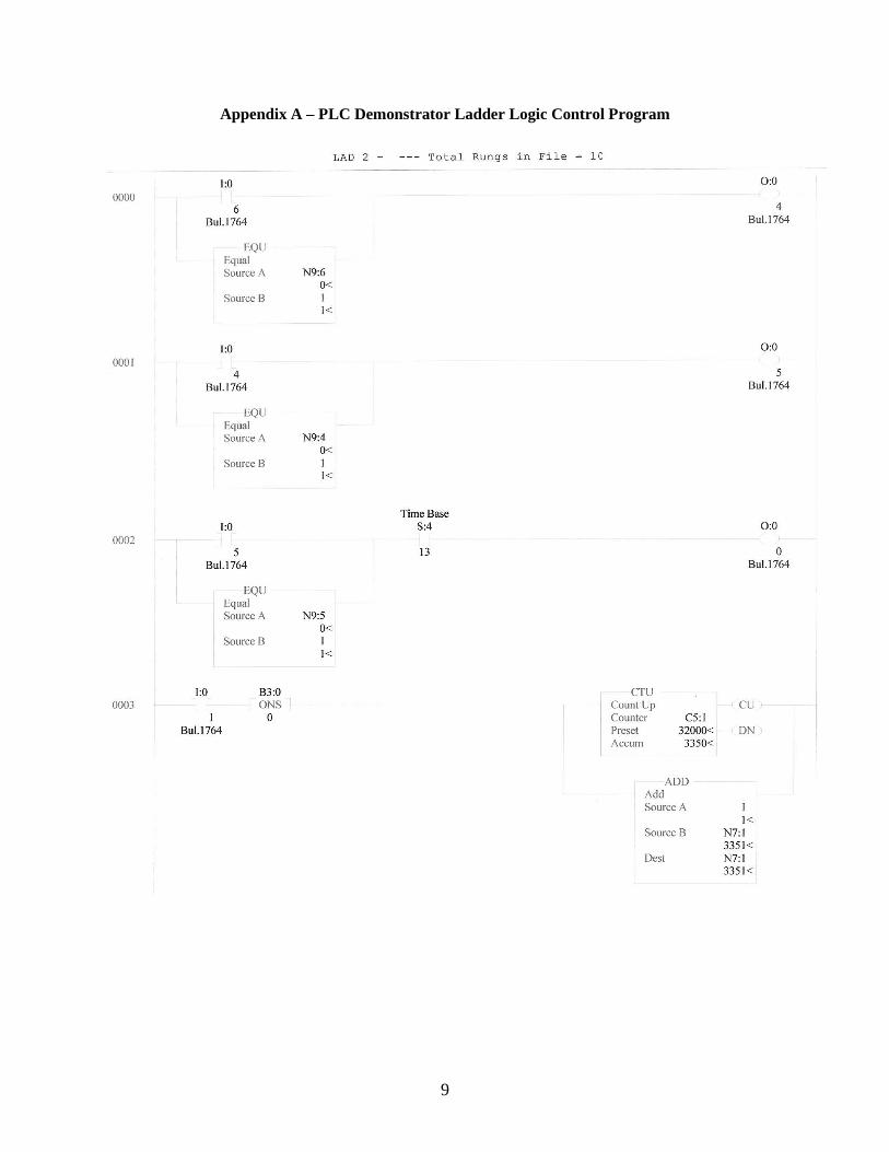
Figure 3 – Schematic Diagram of PLC System Components and Wiring 3.0 PLC Demonstration Procedure The ladder logic control program used to run this demonstration platform is given in Appendix A. Note that the ladder logic diagram has ten basic control rungs (0 thru 9). Rung 0 is used to turn on an incandescent light or other 120 VAC load (not shown in Figure 2). This is done either by turning on
4
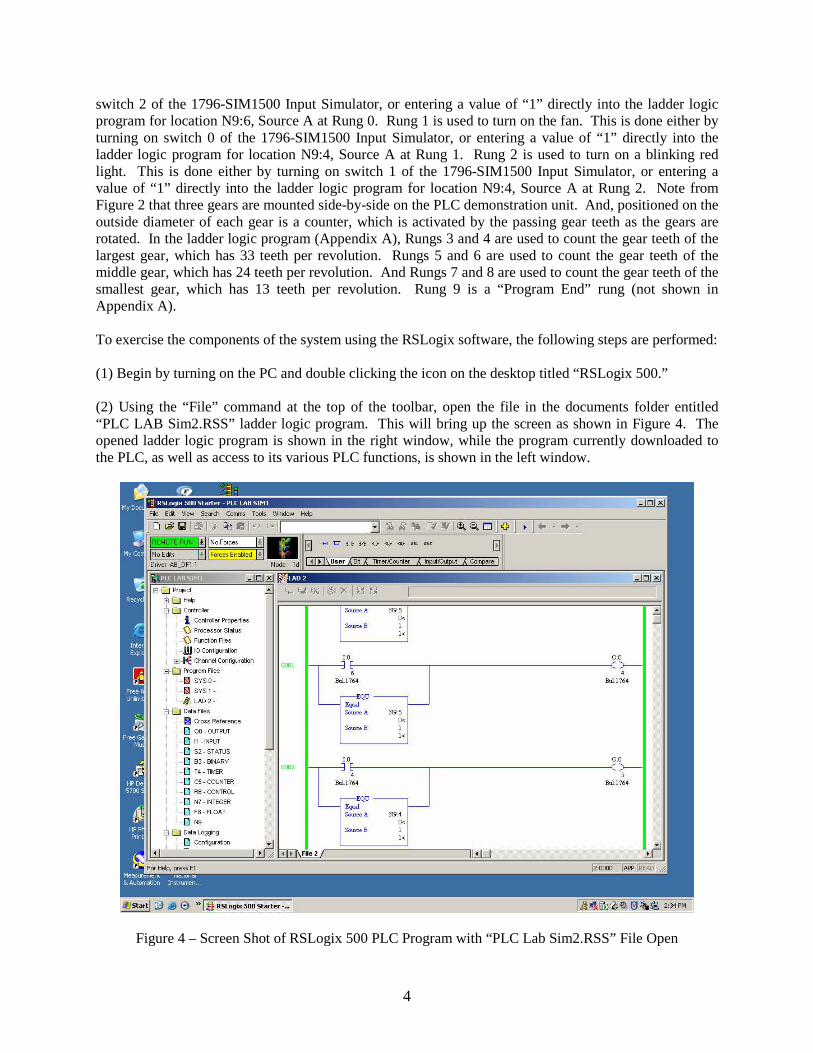
switch 2 of the 1796-SIM1500 Input Simulator, or entering a value of “1” directly into the ladder logic program for location N9:6, Source A at Rung 0. Rung 1 is used to turn on the fan. This is done either by turning on switch 0 of the 1796-SIM1500 Input Simulator, or entering a value of “1” directly into the ladder logic program for location N9:4, Source A at Rung 1. Rung 2 is used to turn on a blinking red light. This is done either by turning on switch 1 of the 1796-SIM1500 Input Simulator, or entering a value of “1” directly into the ladder logic program for location N9:4, Source A at Rung 2. Note from Figure 2 that three gears are mounted side-by-side on the PLC demonstration unit. And, positioned on the outside diameter of each gear is a counter, which is activated by the passing gear teeth as the gears are rotated. In the ladder logic program (Appendix A), Rungs 3 and 4 are used to count the gear teeth of the largest gear, which has 33 teeth per revolution. Rungs 5 and 6 are used to count the gear teeth of the middle gear, which has 24 teeth per revolution. And Rungs 7 and 8 are used to count the gear teeth of the smallest gear, which has 13 teeth per revolution. Rung 9 is a “Program End” rung (not shown in Appendix A). To exercise the components of the system using the RSLogix software, the following steps are performed: (1) Begin by turning on the PC and double clicking the icon on the desktop titled “RSLogix 500.” (2) Using the “File” command at the top of the toolbar, open the file in the documents folder entitled “PLC LAB Sim2.RSS” ladder logic program. This will bring up the screen as shown in Figure 4. The opened ladder logic program is shown in the right window, while the program currently downloaded to the PLC, as well as access to its various PLC functions, is shown in the left window.
Figure 4 – Screen Shot of RSLogix 500 PLC Program with “PLC Lab Sim2.RSS” File Open
5
(3) Click on the pull down menu “Remote Run” in the upper left corner of the screen and select the “Download” option. This will download the currently opened program to the PLC. With the ladder logic program “PLC Lab Sim2.RSS” downloaded to the PLC, there are two options for running its ladder logic: (a) The PLC can simply be powered on with 120 VAC and ladder logic operated using the PLC and associated hardware without the RSLogix 500 software running; or (b) The PLC can be operated in conjunction with the RSLogix 500 software running interactively at the same time. This is done by using the “Remote Run” pull down menu in the upper left corner of the RSLogix 500 software and selecting the “Go Online” option. Running “online” with the ladder logic software open together with the PLC operating allows the user the additional option of modifying inputs to the ladder logic (i.e., turning on switches, etc.) through software input. (4) To test the ladder logic features, flip the toggle switch “0” of the 1796 SIM1500 Input Simulator to the up position. Note that the fan turns on. This occurs because output 5 (O:0/5) of the PLC is activated from 0, OFF to 1, ON. Referencing rung 1 of the ladder logic diagram in Appendix A, it is seen that O:0/5 (portrayed as a load on the right side of rung 1 of the ladder logic diagram) is activated when input 4 (I:0/4, a ladder logic switch) is activated to 1, ON. This is done by physically moving toggle switch 0 of the 1796 SIM1500 Input Simulator in the up position, completing the 24 VDC circuit. The wiring diagram of Figure 3 shows how all this is accomplished via hardware. Here, it is seen that 120 VAC is brought in to power the fan through a relay (left side relay). This relay acts as a switch, which is activated only when the other side (24 VDC side) of the relay closes the contacts to the 120 VAC circuit via a 24 VDC signal from the PLC. This 24 VDC signal is activated only when output 5 (O:0/5) on the PLC is given a value of “1.” And, of course, as stated earlier, this output is activated through input I:0/4. The input I:0/4 is physically connected to the high (plus) side of the 24 VDC circuit via switch 0 of the 1796 SIM 1500 Input Simulator. The ground side of this circuit is connected to the DC COM (common) of the PLC on the input side, as shown in Figure 14. The fan can also be turned on by entering a value of “1” directly into the ladder logic program for location N9:4, Source A at Rung 1. This can also be done by opening the N9 folder (lower left window of the RSLogix 500 software) and entering a value of “1” in location 4. The fan can be turned off by entering a value of “0” in location N9:4 using either of these methods. Finally, it is important to note that activating the fan using a 24 VDC relay switch, isolates the 120 VAC circuit from the PLC and switching functions, making the operation of turning the fan on safer. (5) Next, flip the toggle switch “1” of the 1796 SIM1500 Input Simulator to the up position. Note that the blinking red light turns on. This occurs because output 0 (O:0/0) of the PLC is activated from 0, OFF to 1, ON. Referencing rung 2 of the ladder logic diagram in Appendix A, it is seen that O:0/0 (portrayed as a load on the right side of rung 1 of the ladder logic diagram) is activated when input 5 (I:0/5, a ladder logic switch) is activated to 1, ON. This is done by physically moving toggle switch 1 of the 1796 SIM1500 Input Simulator in the up position, completing the 24 VDC circuit. The ladder logic also shows a time base switch, or timing delay, S:4/13, in-line with the I:0/5 input and I:0/0 output. This software delay is actually what causes the red light to turn on and off at regular intervals, that is, to blink. The wiring diagram of Figure 3 shows how the red blinking light is activated via hardware. Here, it is seen that 24 VDC power is brought from the input side of the PLC over to the output side through output 0 common (VDC 0). The +24 VDC connection is completed through VDC 0 and O:0/0 when I:0/5 is turned ON. The 24 VDC common side is connected from the 24 VDC common screw terminal (COM) on the input side of the PLC, through the 24 VDC screw connector (see Figure 14) and then to the ground (-) side of the red blinking light. The red blinking light can also be turned on by entering a value of “1” directly into the ladder logic program for location N9:5, Source A at Rung 2. This can also be done by opening the N9 folder (lower left window of the RSLogix 500 software) and entering a value of “1” in location 5. The red blinking light can be turned off by entering a value of “0” in location N9:5 using either of these methods.

6
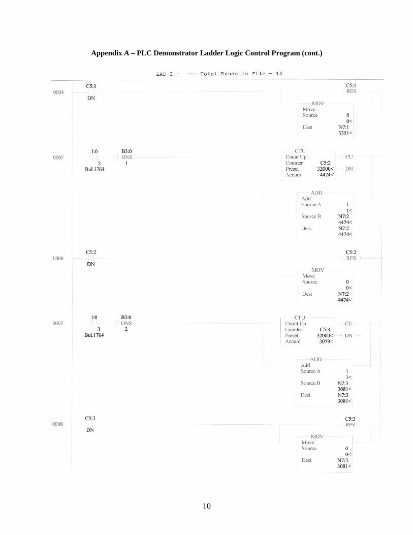
(6) Toggle switch “2” of the 1796 SIM1500 Input Simulator activates the 120 VAC powered incandescent light bulb (not currently installed). The activation of this 120 VAC load is accomplished in a manner analogous to the fan activation. In this case, the 120 VAC load is energized because output 4 (O:0/4) of the PLC is activated from 0, OFF to 1, ON. Referencing rung 0 of the ladder logic diagram in Appendix A, it is seen that O:0/4 (portrayed as a load on the right side of rung 1 of the ladder logic diagram) is activated when input 6 (I:0/6, a ladder logic switch) is activated to 1, ON. This is done by physically moving toggle switch 2 of the 1796 SIM1500 Input Simulator in the up position, completing the 24 VDC circuit. The wiring diagram of Figure 3 shows how this is accomplished via hardware. Here, it is seen that 120 VAC is brought in to power the load through a relay (right side relay). This relay acts as a switch, which is activated only when the other side (24 VDC side) of the relay closes the contacts to the 120 VAC circuit via a 24 VDC signal from the PLC. This 24 VDC signal is activated only when output 4 (O:0/4) on the PLC is given a value of “1.” As stated earlier, this output is activated through input I:0/6. The input I:0/6 is physically connected to the high (plus) side of the 24 VDC circuit via switch 2 of the 1796 SIM 1500 Input Simulator. The ground side of this circuit is connected to the DC COM (common) of the PLC on the input side, as shown in Figure 3. The 120 VAC load can also be turned on by entering a value of “1” directly into the ladder logic program for location N9:6, Source A at Rung 0. This can also be done by opening the N9 folder (lower left window of the RSLogix 500 software) and entering a value of “1” in location 6. The load can be turned off by entering a value of “0” in location N9:6 using either of these methods. Again, it is important to note that activating the 120 VAC load using a 24 VDC relay switch, isolates the 120 VAC circuit from the PLC and switching functions, making the operation of turning the load on safer. (7) Frequency counting of the teeth on the large gear is performed using rungs 3 and 4 of the ladder logic program, as shown in Appendix A, as the gear is rotated using the crank handle shown in Figure 2. When a gear tooth of the large gear passes by the sensor located on the outside diameter of the large gear, a small red LED on the sensor illuminates, and input 1, I:0/1, is activated on the PLC by completion of the 24 VDC circuit (see Figure 3). Thus, the voltage in the circuit changes from 0 to 24 VDC when this happens. Rung 3 of the ladder logic program (Appendix A) shows that this closes the I:0/1 switch contact, and then sends a 1 bit to the binary location B3:0/0. This resets the PLC so that the counter (load on the right side of rung 3) makes only one count for each rise in voltage from 0 to 24 VDC. If this were not included in the ladder logic, the scanning frequency of the PLC would cause the counter to register a very high number of counts corresponding to the scanning rate of the PLC. Rung 3 of the ladder logic program shows that the counter counts UP each time it sees a rise in the voltage signal of the circuit from 0 to 24 VDC, and stores it in location C5:1. In addition, this count is stored in an integer location, N7:1, which is included so that this number can be accessed by other control programs (e.g., Visual Basic, which could use the stored number to perform so other task). This is done because the counter location C5:1 is not accessible by external programs. Rung 4 is used to reset the counter once it gets to a preset value. In the current case, the preset value is set to 32000 counts. This is shown in the counter function on the right side of rung 3 as “Preset,” while the accumulated number of counts up to the current time is shown just below it as “Accum.” Rung 4 shows that when the current count value stored in C5:1 reaches the preset value of 32000, the counter is reset to zero. That reset value is also reset in the N7:1 location whenever a reset occurs. (8) The counting of gear teeth on both the medium and small size gears is accomplished in the same manner as used for the large gear. Rungs 5 and 6 of the ladder logic are used to count gear teeth of the medium gear, which uses input I:0/2, binary location B:0/1, counter location C5:2 and integer location N7:2 in performing the same tasks as rungs 3 and 4 in the ladder logic for the large gear. Rungs 7 and 8 of the ladder logic are used to count gear teeth of the small gear, which uses input I:0/3, binary location B:0/2, counter location C5:3 and integer location N7:3 in performing the same tasks as rungs 3 and 4 in the ladder logic for the large gear.
7
(9) The part counter shown in Figure 2 is currently not completely wired into the PLC hardware, and is therefore not included in the ladder logic program of Appendix A. It will be added at a latter time. 4.0 Suggested Exercises for Exploration of PLC’s There are many exercises that can be performed to gain a deeper understanding of ladder logic and how it can be used together with a PLC to accomplish control of a system. The following exercises are suggested to be completed by students wishing to investigate the capabilities of PLC operation. Exercise 1: Edit the “PLC Lab Sim2.RSS” program to accomplish the following: Selector switches 0-2 of the 1796 SIM 1500 Input Simulator must all be turned ON (i.e., toggled in the UP position) before the fan turns ON. Exercise 2: Edit the “PLC Lab Sim2.RSS” program to accomplish the following: Turn on the red light source, output 0 (O:0/0), without allowing it to blink, only if output 4 (2nd 120 VAC) is ON, OR input 4 (Switch 0) is ON, AND input 5 (Switch 1) is not ON. Exercise 3: Edit the “PLC Lab Sim2.RSS” program to accomplish the following: When the count of gear teeth on the large gear is greater than the count of gear teeth on the middle gear, turn on the red light source, output 0 (O:0/0), without allowing it to blink. 5.0 Results of Using the PLC Platform in a Graduate Course A graduate course in manufacturing was recently taught by the author for seven students, entitled “Computer Control of Manufacturing.” This course covered topics in manufacturing ranging from numerical control and automation to sensors, actuators, control systems, and the use of PLCs. The topic of PLC’s was covered as the eleventh of twelve three-hour lectures given over the entire semester. The lecture was quite extensive, covering Chapter 8 in Reference [1], including the characteristics and elements of PLCs, the use of truth tables, Boolean algebra, ladder logic and associated symbolism, and examples demonstrating discrete process control using both logic (event) driven and sequence (time) driven system changes. Students were then asked to read the corresponding material in the text [1] for homework, given instruction for about 15 minutes on the use of the PLC platform and its associated software as described above, and then given a PLC project to complete. The project required students to complete the exercises, as outlined in section 4.0 of this paper, and then summarize their results in a brief technical memo. It should be noted here that only one of the seven graduate students in the course had any previous experience using PLCs, and none had any experience using the RSLogix software. Although not conclusive, the results of the project were very encouraging. The students were able to explore some of the capabilities of PLCs, within the design limitations of the platform, and required very little external input. On the project itself, students’ scores averaged 86%, indicating they generally understood the basic operation of the PLC as they completed the project. And feedback on the project was also very good from the students, as reflected in their end of semester evaluations. Positive comments included “course fills a need that addresses automation in manufacturing” and “liked the hands-on nature of the course.” Negative comments included “the use of software programs with little knowledge of them was a struggle.” Students suggested that more time be devoted to topics such as PLCs and PID control. Overall, students rated the usefulness of the projects run in the course (the PLC project was one of three given) as a 4.6 out of 5. It is the author’s interpretation of this feedback that students found the PLC project helpful, especially the ability to learn through exploration of a hands-on platform, but that more time and a broader range of exploration are needed. These issues are currently being addressed and will be incorporated into an updated PLC platform, as described in the following section. 6.0 Incorporation of the PLC Platform in the Undergraduate Curriculum Figure 5 shows a more complex control system relative to the existing system, a storage tank, and its corresponding ladder logic control diagram, which is planned to be incorporated into the PLC platform before it is used in a new undergraduate manufacturing elective course. Note that this control system
8
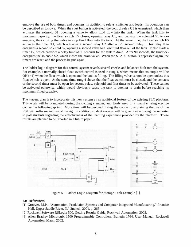
employs the use of both timers and counters, in addition to relays, switches and loads. Its operation can be described as follows: When the start button is activated, the control relay C1 is energized, which then activates the solenoid S1, opening a valve to allow fluid flow into the tank. When the tank fills to maximum capacity, the float switch FS closes, opening relay C1, and causing the solenoid S1 to de-energize, thus closing the valve to stop fluid flow into the tank. At the same time, the float switch FS activates the timer T1, which activates a second relay C2 after a 120 second delay. This relay then energizes a second solenoid S2, opening a second valve to allow fluid flow out of the tank. It also starts a timer T2, which provides a delay time of 90 seconds for the tank to drain. After 90 seconds, the timer de-energizes the solenoid S2, which closes the drain valve. When the START button is depressed again, the timers are reset, and the process begins again. The ladder logic diagram for this control system reveals several checks and balances built into the system. For example, a normally closed float switch control is used in rung 1, which means that its output will be ON (=1) when the float switch is open and the tank is filling. The filling valve cannot be open unless this float switch is open. At the same time, rung 4 shows that the float switch must be closed, and the contacts of the second timer must be open for second relay, solenoid and first timer to be activated. These cannot be activated otherwise, which would obviously cause the tank to attempt to drain before reaching its maximum filled capacity. The current plan is to incorporate this new system as an additional feature of the existing PLC platform. This work will be completed during the coming summer, and likely used in a manufacturing elective course the following spring. More time will be devoted during the course to explaining the use of the RSLogix software and use of the rig. In addition, student surveys will be given twice during the semester to poll students regarding the effectiveness of the learning experience provided by the platform. These results are planned to be reported in a future paper.
Figure 5 – Ladder Logic Diagram for Storage Tank Example [1] 7.0 References [1] Groover, M.P., “Automation, Production Systems and Computer-Integrated Manufacturing,” Prentice
Hall, Upper Saddle River, NJ, 2nd ed., 2001, p. 268. [2] Rockwell Software RSLogix 500, Getting Results Guide, Rockwell Automation, 2002. [3] Allen Bradley Micrologix 1500 Programmable Controllers, Bulletin 1764, User Manual, Rockwell
Automation, March 2002.
9
Appendix A – PLC Demonstrator Ladder Logic Control Program
10
Appendix A – PLC Demonstrator Ladder Logic Control Program (cont.)