development of a new spinning gait for a planar snake robot using central pattern...
TRANSCRIPT
Intel Serv Robotics (2013) 6:109–120DOI 10.1007/s11370-013-0129-3
ORIGINAL RESEARCH PAPER
Development of a new spinning gait for a planar snake robotusing central pattern generators
Shahir Hasanzadeh · Alireza Akbarzadeh
Received: 1 June 2012 / Accepted: 22 January 2013 / Published online: 7 March 2013© Springer-Verlag Berlin Heidelberg 2013
Abstract In this paper, we first present dynamic equationof n-link snake robot using Lagrange’s method in a simplifiedmatrix form and verify them experimentally. Next, we intro-duce a new locomotion mode called spinning gait. Centralpattern generators (CPGs) are used for online gait genera-tion. To realize spinning gait, genetic algorithm is used to findoptimal CPG network parameters. We illustrate both theoret-ically, using derived robot dynamics and experimentally thatthe CPG-based online gait generation method allows con-tinuous and rather smooth transitions between gaits. Lastly,we present an application where the snake robot is guidedfrom an initial to final position while avoiding obstacles bychanging CPG parameters.
Keywords Snake robot · Central pattern generator ·Serpentine gait · Dynamic · Genetic algorithm
1 Introduction
Snake robots are serially connected, multilink-articulatedmechanisms, which propel themselves by body shape undu-lations. One of the first known biologically inspired snakerobots was built by Hirose and co-workers at the end of 1972[1]. His robot used wheels to create a no side-slip conditionfor each of the links. A survey of snake robot designs waspresented by Hophkins [2].
Snake robots can move with different modes of locomo-tion (gaits). Serpentine, concertina and side-winding are thethree common snake-like gaits in snake robots [3]. There are
S. Hasanzadeh · A. Akbarzadeh (B)Center of Excellence on Soft Computing and IntelligentInformation Processing, SCIIP,Mechanical Engineering Department,Ferdowsi University of Mashhad, Mashhad, Irane-mail: [email protected]
also non- snake-like gaits which do not exist in nature but areuseful in snake robot motion. Flapping gait [4] is an exampleof non-snake-like gaits. More recently, a novel gait, calledFHS, that keeps the head link of the robot towards its target,was introduced by the authors [5].
Modeling and control of snake robot have been addressedby many researchers. A comprehensive survey on snake robotmodeling and locomotion has been performed by [6]. Ingeneral, control methods may be classified into two broadclasses. Sine wave trajectory tracking [7] and online trajec-tory generation [8]. Recent studies use central pattern genera-tors, CPGs, to generate desired trajectories which can be usedby an online controller. CPGs are neural circuits found in bothinvertebrate and vertebrate animals that can produce rhyth-mic patterns of neural activity without receiving rhythmicinputs. CPGs present several interesting properties includingdistributed control, the ability to deal with redundancies, fastcontrol loops, and allowing modulation of locomotion bysimple control signals. These properties, when transferredto mathematical models, make CPGs interesting buildingblocks for locomotion controllers in robots. There are manyresearches who have realized control of animal-like robotsbased on CPG model. A good review of application of CPGsin locomotion control of robots can be found in [9].
In the area of snake robots, Crespi et al. [10] proposedCPG-based controller for amphibious snake-like robot andconstructed an experimental model. Ma et al. [11,12] pro-posed different control architectures for serpentine locomo-tion based on CPG network and simulated them consideringmechanical dynamics of a snake robot. More recently, Ryuet al. [13] proposed a CPG-based control architecture whichwas able to adapt the motion of the robot to varyingcoefficients of body-ground friction. In all of these works,CPGs were used to change the parameter of a specific gait.In the present paper, we aim to study the capability of CPGs in
123

110 Intel Serv Robotics (2013) 6:109–120
producing smooth transitions between different gaits andapply it to multimodal locomotion of snake robot. In partic-ular, we try to contribute to answer the following questions:(1) how different gaits can be generated for different pur-poses, and (2) how a smooth transition between differentgaits can be achieved.
The goal of this research is to contribute to generate loco-motion that more closely imitates real snakes in nature byallowing the robot the choice of a new gait as well as usingCPGs as its motion generator which also used by real snakes.To do this, in Sect. 2, we drive the dynamic equation for ann-link snake robot using coulomb friction model. This modelwill enable us to run our simulation and perform gait para-meter optimization. To improve locomotion, we introduce anew gait called spinning gait in Sect. 3. This gait allows therobot to turn with a minimum radius. This feature enablessnake robot to improve its maneuverability in environmentfull of obstacles. A quick and smooth transition between gaitsis a difficult problem that is merely addressed in literature. InSect. 4 and 6, we demonstrate both theoretically and exper-imentally that CPGs may be used to overcome this problemby allowing a continuous and a smooth transition betweenserpentine and spinning gaits.
2 Snake robot model
A planar snake robot consisting of n links connected throughn−1 joints is depicted in Fig. 1a. Each link is rigid with uni-formly distributed mass and is equipped with a torque actu-ator (motor). Moment of inertia of the motors is neglected.Each link is of mass mi , length li and moment of inertiaJi . Let (xci , yci ) and θi define the center of gravity and theangle between the link and the x axis, respectively. Valuesof di represent location of mass center of i th link. (xb, yb) iscoordinate of the end of tail link.
Free-body diagram of the robot is depicted in Fig. 1b,where Ti are the joint torques from the actuators, and fni
and fti are the force due to the friction between the linksand the horizontal surface. As illustrated in Fig. 1b, ϕi , (i =1, . . ., n − 1) are relative angles of two adjacent links.
To generate significantly different friction coefficients innormal and tangential directions, a wheel or a blade may beattached to each link. We consider a simple coulomb frictionmodel to simulate friction between each link and ground:
fei = −mi gμesign(vei ), (1)
where e = t, n (t and n represents tangential and normaldirections). g is the gravity constant. μt and μn are nor-mal and tangential coulomb friction coefficients. Subscripti corresponds to the i th link, fti and fni are friction forcesin tangential and normal directions, respectively. vi t and vin
are velocities of the center of mass of i th link. The signum
function is denoted by sign(x). The friction forces along thex and y axis can easily be obtained by coordinate transfor-mation from t-n to x-y. According to Fig. 1a, the coordinatesof the mass center of i th link are
yci = yb +i−1∑
j=1
l j sin θ j + di sin θi (2)
xci = xb +i−1∑
j=1
l j cos θ j + di cos θi (3)
Velocities of mass center of each link are obtained by takingderivation from Eqs. 2 and 3. Thus, the kinetic energy of then-link snake robot can be defined as
K =n∑
i=1
[1
2Ii θ
2i + 1
2mi (x2
c + y2c )
](4)
Substituting derivatives of Eqs. 2 and 3 into Eq. 4, and sum-marizing will result in
K =n∑
i=1
[1
2(Ii + mi d
2i )θ2
i + 1
2mi (x2
b + y2b )
]
+n∑
i=1
⎧⎨
⎩mi di θi
i−1∑
j=1
[l j θ j cos(θi − θ j )
]⎫⎬
⎭
+n∑
i=1
[mi di θi (yb cos θi − xb sin θi )
]
+n∑
i=1
⎧⎨
⎩mi
i−1∑
j=1
[l j θ j (yb cos θ j − xb sin θ j )
]⎫⎬
⎭
+n∑
i=1
⎧⎪⎨
⎪⎩1
2mi
⎡
⎣i−1∑
j=1
(l j sin θ j θ j )
⎤
⎦2
+1
2mi
⎡
⎣i−1∑
j=1
(l j cos θ j θ j )
⎤
⎦2⎫⎪⎬
⎪⎭(5)
The instantaneous system configuration will be known uponhaving (xb, yb) and θi (1 ≤ i ≤ n). Therefore, the generalizedcoordinates are selected as follows
q j = [θ1, θ2, . . . , θn, xb, yb] (6)
As there is no variation in potential energy, the equations ofmotion can be written as
d
dt
(∂K
∂qi
)+ ∂K
∂qi−Qqi
= 0 (i = 1, 2, . . . n + 2) (7)
Non-conservative forces that do work when generalizedcoordinates are given virtual displacements are actuators
123

Intel Serv Robotics (2013) 6:109–120 111
Fig. 1 n-link snake robot: geometrical parameters (a), free body diagram (b)
torques (Ti i = 1, 2, . . ., n − 1) and friction forces ( fxi andfyi i = 1, 2, . . ., n). Taking derivative from Eqs. 2 and 3,generalized forces,Qqi , can be obtained as
Qθ j = d j ( fyi cos θ j − fxi sin θ j )
+ l j
⎡
⎣cos θ j
n∑
i= j+1
( fyi )− sin θ j
n∑
i= j+1
( fxi )
⎤
⎦
+ Tj−1 − Tj (8)
Qxb =n∑
i=1
( fxi ) (9)
Qyb =n∑
i=1
( fyi ), (10)
where Qθ j are generalized forces related to generalized coor-dinate θ j .Qxb and Qyb are generalized forces related to xb
and yb, respectively. By substituting Eqs. 5, 8, 9 and 10 intoLagrangian formulation, Eq. 7, the dynamic model for then-link snake robot can be derived as
BT = M(θ)q + H(θ, θ ) + F(θ) (11)
where M(θ) is the (n + 2) × (n + 2) positive definite andsymmetric inertia matrix, H(θ, θ ) is the (n + 2)×1 matrixrelated to centrifugal and Coriolis terms with Hi as its i thmember, F(θ) is an (n + 2)×1 matrix related to frictionforces, B is an (n+2)×(n−1) constant matrix.T is (n−1)×1matrix of input torques and q, q, q are (n + 2) × 1 matrixof generalized coordinates and their derivatives. θ, θ , θ aren×1 matrix of links absolute angles and their derivatives.The details of the terms M, H, B and F used in Eq. 11 arepresented in Appendix. The final dynamic equation, Eq. 11,has a simplified matrix format and can easily be expandedfor any number of links.
2.1 Torque to motion
The forward dynamic problem deals with finding motion ofthe snake robot, while input joint torques are given. To solvethe forward dynamic problem, we simply solve Eq. 11 usingEuler method. Equation 11 is an (n + 2)-dimensional linearequation of (n + 2) unknown variables (q ∈ Rn+2). By solv-ing this equation, we can obtain angular acceleration for alllinks (θ ∈ Rn) as well as the acceleration of a point at the endof tail link (xb, yb). By integration, links angular velocities(θ ), joint angles (θ), position (xb, yb) and velocity (xb, yb) ofa point at the end of tail link can all be obtained. Therefore,snake robot motion is derived for when input torques for alljoints are supplied.
2.2 Shape to motion
In this section, we attempt to drive at the motion of the snakerobot given the relative angles of the adjacent links. Anotherwords, given instantaneous relative angles and their deriva-tives (ϕ, ϕ, ϕ), Eq. 11 can be solved to find applied torquesand coordinates of the tail of the robot which will determinethe motion of the robot. Relation between absolute value andrelative value of joint angles is:
ϕi = θi+1 − θi , (12)
where i = 1, 2, . . ., n − 1. We can rewrite Eq. 12 in matrixform as,
θ = Eϕ + eθ1, (13)
where ϕ is an (n-1)-dimensional vector of [ϕ1, ϕ2, . . ., ϕn−1] ,θ1 is the absolute angle of the tail link, Ei j and e are defined as,
Ei j ={
1 i > j0 others
e = [1, 1, . . . 1]T (14)
123
112 Intel Serv Robotics (2013) 6:109–120
To obtain motion based on given shape, we first decouple thedynamic Eq. 11 into two parts
p M(θ)θ + p N (θ)rb + p H(θ, θ ) + p f (θ) = DT (15)q M + (θ)θ +q Nrb +q H(θ, θ ) + q f (θ) = 0, (16)
where
M =[ p Mn×n
p Nn×2q M2×n
q N2×2
], H =
[ p Hn×1q H2×1
], rb =
[xb
yb
]
(17)
Matrix p f , q f and D are defined in Appendix. By substitut-ing second derivative of Eq. 13 into Eq. 16, we arrive at,
rb = −q N−1(q M θ + q H θ + q f )
= −q N−1q M(E φ + eθ1) − q N−1(q H θ + q f ) (18)
Substituting Eq. 18 into Eq. 15, we obtain
DT +(p N q N−1q M− p M)eθ1 = (p M− p N q N−1q M)E φ
−p N q N−1(q H θ+q f )
+p H θ + p f (19)
Equation 19 is an n-dimensional linear equation represent-ing the dynamic of the n-link snake robot. In the directdynamic formulation, inputs are the n-dimensional vector ofjoint angles [ϕ1, ϕ2, . . ., ϕn−1] and the outputs are n unknownvariables θ1 ∈ R and torque, T ∈ Rn−1. Therefore, by solv-ing Eq. 19, we can obtain the joint torques, Ti , and tail linkrotation acceleration, θ1. Substituting these values back intoEq. 18 will obtain acceleration of the tail end, rb. The taillink joint angle (θ1) and its angular velocity (θ1) as well asvelocity of the tail end (rb) and its moving distance (rb) areall obtained through integration. The complete parametersdefining robot motion are derived for the case when changesin body shape, ϕ, are known. Therefore, upon specifyingchanges in body shape, we can drive at necessary joint torquesto generate the desired robot motion. Our use of the deriveddynamic equation in this paper is twofold: (1) as simulationtool for evaluation of the proposed control schemes (2) forcalculation of fitness function of GA in Sect. 3.2.
3 CPG control locomotion
The CPGs found in vertebrates are composed of neural oscil-lators. Real neurons have very complicated behaviors and,therefore, it is difficult to build a mathematical model toclosely simulate it. CPG-based approaches for locomotioncontrol often use systems of coupled nonlinear oscillatorsfor generating the traveling waves necessary for locomotion([10,14,15]). These approaches are implemented as differen-tial equations integrated over time with the goal to producethe traveling wave as a limit cycle. The system is then robust
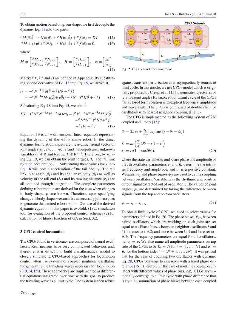
Fig. 2 CPG network for snake robot
against transient perturbation as it asymptotically returns tolimit cycle. In this article, we use CPGs model which is origi-nally proposed by Crespi et al. [15] to generate trajectories ofrelative joint angles for snake robot. Limit cycle of the CPGshas a closed form solution with explicit frequency, amplitudeand wavelength. The CPGs is composed of double chain ofoscillators with nearest neighbor coupling (Fig. 2).
The CPG is implemented as the following system of 2Ncoupled oscillators [15]:
θi = 2πνi +∑
j
wi j sin(θ j − θi − φi j )
ri = ai
(ai
4(Ri − ri ) − ri
)
xi = ri (1 + cos(θi )), (20)
where the state variables θi and ri are phase and amplitude ofthe i th oscillator, parameters νi and Ri determine the intrin-sic frequency and amplitude, and ai is a positive constant.Weights wi j and phase biases φi j are used to define couplingbetween oscillators. Variable xi is the rhythmic and positiveoutput signal extracted out of oscillator i . The values of jointangles, ϕi , are determined by taking the difference betweensignals from the top and bottom oscillators.
ϕi = xi − xi+N (21)
To obtain limit cycle of CPG, we need to select values forparameters defined in Eq. 20. The phase biases, ∅i j , betweenpaired oscillators which are working on each joint are setequal to π . Phase biases between neighbor oscillators i andi+1 are set to + �∅i and those between i+1 and i are set to -�∅i . The frequency parameters are equal for all oscillators,i.e. νi = ν. We also name all amplitude parameters on topside of the CPGs to be Ri = Ti for i = (1, . . ., N ) and Ri =Bi for the bottom side, i = (N + 1, . . ., 2N ). It was provedthat for the case of coupling two oscillators with dynamicEq. 20, CPGs converge to sinusoids with a fixed phase dif-ference [15]. Therefore, in the case of multiple coupled oscil-lators with different values of phase bias, �∅i , CPGs asymp-totically converge to a limit cycle with phase difference thatis equal to summation of phase biases between each coupled
123

Intel Serv Robotics (2013) 6:109–120 113
Table 1 CPG settings for serpentine gait
Parameter names Symbol Value
Top side amplitude parameters Ti T
Bottom side amplitude parameters Bi B
Connection weights wi j 4
Positive constant ai 10
Phase bias, between paired oscillators φi j π
Phase bias, between descending neighbor oscillators φi j −�φ
Phase bias, between ascending neighbor oscillators φi j +�φ
Fig. 3 Oscillatory angles ϕ1(t) and ϕ4(t) for serpentine gait (T =0.25, B = 0.25 and ν = 0.5 are doubled at t = 10 s)
CPGs. The limit cycle is then defined by the following closedform solution for the i th actuated joint:
ϕi (t) = Ti−Bi +(Ti +Bi ) cos
⎛
⎝2πνt+i∑
j=1
�φ j +φ0
⎞
⎠,
(22)
where ∅0 depends on the initial conditions. In this equation,the values of Ti − Bi and Ti + Bi determine offset and ampli-tude of the i th joint angle, respectively. For the rest of thispaper, we name CPGs parameters along with coupling coef-ficients, CPG network parameters.
3.1 Realization of serpentine gait
Serpentine movement shown in Fig. 4 is one we see in almostall snakes. The most straightforward way to generate serpen-tine gait in a serial chain is by having the joint angles varysinusoidally with a common frequency and a constant phase-lag between consecutive joints. Considering Eq. 22, settingCPG parameters as Table 1 leads the robot to move withserpentine gait.
To change robot speed, we use CPG to change the valuesof amplitude (T + B) and frequency (υ) at t =10 s, while
Fig. 4 Snake robot moving with serpentine gait (Motion is the resultof relative joint angle shown in Fig. 3)
Fig. 5 Oscillatory angles ϕ1(t) and ϕ4(t) for serpentine gait (offsetsare increased at t=10 s)
other control parameters remain constant (Fig. 3). Resultantmotion of the robot is shown in Fig. 4. To obtain this motion,joint angles generated by CPGs, dynamic equation of CPGs(Eq. 20) is solved along with dynamic equation of the robot(Eq. 18 and Eq. 19). Euler method is used for solving bothset of equations with the same integration step size, 1ms.Robot parameters used in simulation are li =2m, di =1m,Ji =0.33 kgm2, μt =0.05, μn=0.5. Next, to induce rotation,value of offset (T − B) is changed at t =10 s, while othercontrol parameters remain constant (Fig. 5). The resultantmotion of the robot is simulated using dynamic equationsand is shown in Fig. 6.
3.2 Realization of spinning gait
In this section, we introduce spinning gait which will allowrobot to turn with minimum radius. When the robot encoun-ters an obstacle, it is desirable to turn around as quickestas possible with minimum radius of curvature. Spinning gaitfurther improves snake’s maneuverability. In this locomotion
123

114 Intel Serv Robotics (2013) 6:109–120
Fig. 6 Snake robot turning with serpentine gait (Motion is the resultof relative joint angle shown in Fig. 5)
mode, robot spins around itself while its mass center followsa circle with a small radius. Serpentine gait may also be usedto obtain a rotational behavior of snake. This is performed bysetting a large value for offset, T -B. However, this locomo-tion results in entire body of snake following a circular path.This can potentially increase the possibility of collision withobstacles. Therefore, we present a solution on how to adjustCPG network parameter to generate spinning gait.
Problem of finding CPG network parameters for spinninggait is an optimization problem that can be solved with dif-ferent methods. Considering the total system (combinationof mechanical system and neural system), the total dynam-ics is too complicated to discuss analytically. In such case,synthetic approaches are more effective. Since derivative ofthe objective function is not available, only derivative-freeoptimization methods such as Simplex Search or GeneticAlgorithms can be used. Although GA is computationallyexpensive, in this paper, we use it as optimization method,since finding spinning gait parameters is an offline procedure.GA process steps are listed as follows:
• Optimization parameters To reflect the symmetries ofthe robot and to reduce the number of parameters tobe optimized, several parameters are set to the samevalues. Phase biases between opposite neighbor oscil-lators are set to be equal (i.e. Δ∅i = Δ∅i+N−1 forinstance Δ∅1 = Δ∅4). Therefore, optimization para-meters reduced to 11(T1–T4,B1–B4, Δ∅1–Δ∅3).
• Constraints Because of mechanical limit of motor rota-tion angle, the value for the relative joint angle is alsobounded. Considering Eq. 22, the maximum value of therelative joint angle is constrained as,
|Ti − Bi | + |Ti + Bi | ≤ ϕmax,i (i = 1, . . . , N ), (23)
where ϕmax,i is the maximum rotation angle of i th joint.
• Fitness function Fitness function in our study is a functionof CPG network parameters and is calculated by measur-ing orientation of the mid-link during the fixed time oflocomotion simulation, Eq. 24.
Fitness Function = 1/�θmidlink (24)
To find CPG network parameters which generate spinninggait with maximum speed, the difference between minimumand maximum values of the measured mid-link absolute ori-entation has to be maximized. Here, amount of rotation ofthe mid-link is used as a quantitative measure for the rotationof the whole robot. Calculation of fitness function is relatedto mechanical dynamics of the robot as well as friction coef-ficients of the surface which the snake robot moves on. Afteradjusting the CPG network parameters, Eq. 20 is solved, andrelative angle of adjacent links, ϕi , is calculated. Using thesevalues, dynamic Eq. 19 and then Eq. 18 is solved, and motionof the snake robot is derived (Sect. 2.2). The time of simula-tion is crucial for achieving good results. Stable locomotion isusually reached after short amount of time. Prior to this time,instable locomotion, we may get a positive fitness score thatshould be ignored. Therefore, we found, letting the simula-tion run a certain amount of time before starting the fitnessevaluation solves this problem. In this study, we used the ori-entation of the robot after four simulated seconds as startingconfiguration and the orientation after 30 s as end configu-ration to measure the rotation. We also introduce additionalconstraint for the fitness function. We require that motion ofthe center of mass of the whole system must remain in a lim-ited area. We define this area as a circle with radius of 80 %of the length of the robot. If robot exceeds the circle duringsimulation, corresponding genome is destroyed. If this con-straint is not introduced, the optimized parameters found byGA will be that of a serpentine motion.
We find CPG network parameters for given υ = 0.5 rad/sand ϕmax = π /2. Environmental conditions is parameterizedby parameters μt =0.05 μn=0.56. After 300 generations, bestfitness value converges to 0.0708. Best individuals corre-sponding to the best fitness value are T1 = 0.445, T2 =0.445, T3 = 0.785, T4 = 0.785, B1 = 0.785, B2 =0.785, B3 = 0.445, B4 = 0.445, �∅1 = −0.284,
�∅2 = 0, �∅3 = −0.284.Interestingly, optimal CPG parameters have the following
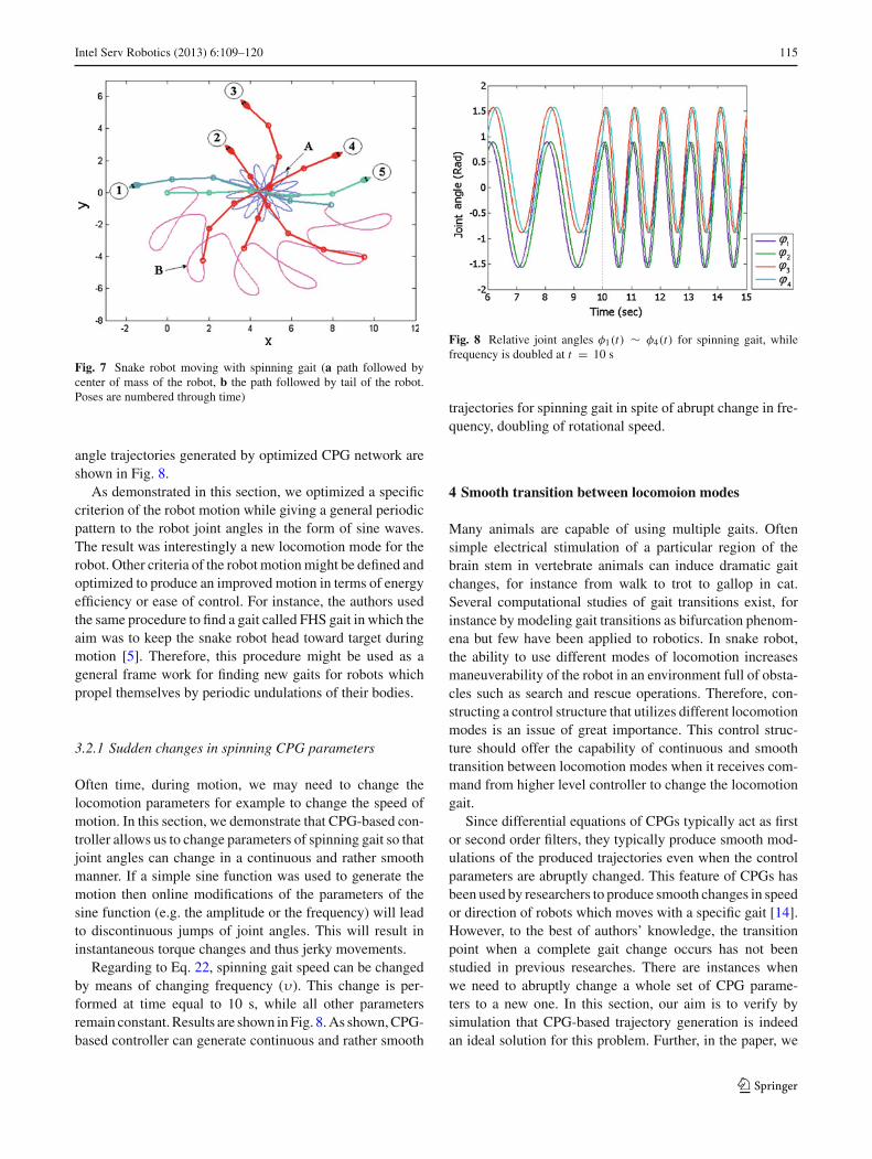
properties: phase differences of the generated waves tend tobe equal except the second one that tends to be zero. Ampli-tudes of the generated waves tend to be equal. Offset termsalso converge to approximately the same values with oppositesigns for first and second CPG relative to third and fourth one.Using these parameters and the dynamic equations, snakerobot achieves spinning gait shown in Fig. 7. The center ofmass of our 5 m long snake moves with speed of 27.16 deg/sin a circle with radius of 3.5 m. As shown, snake robot real-izes a sharp turning using spinning gait. The relative joint
123
Intel Serv Robotics (2013) 6:109–120 115
Fig. 7 Snake robot moving with spinning gait (a path followed bycenter of mass of the robot, b the path followed by tail of the robot.Poses are numbered through time)
angle trajectories generated by optimized CPG network areshown in Fig. 8.
As demonstrated in this section, we optimized a specificcriterion of the robot motion while giving a general periodicpattern to the robot joint angles in the form of sine waves.The result was interestingly a new locomotion mode for therobot. Other criteria of the robot motion might be defined andoptimized to produce an improved motion in terms of energyefficiency or ease of control. For instance, the authors usedthe same procedure to find a gait called FHS gait in which theaim was to keep the snake robot head toward target duringmotion [5]. Therefore, this procedure might be used as ageneral frame work for finding new gaits for robots whichpropel themselves by periodic undulations of their bodies.
3.2.1 Sudden changes in spinning CPG parameters
Often time, during motion, we may need to change thelocomotion parameters for example to change the speed ofmotion. In this section, we demonstrate that CPG-based con-troller allows us to change parameters of spinning gait so thatjoint angles can change in a continuous and rather smoothmanner. If a simple sine function was used to generate themotion then online modifications of the parameters of thesine function (e.g. the amplitude or the frequency) will leadto discontinuous jumps of joint angles. This will result ininstantaneous torque changes and thus jerky movements.
Regarding to Eq. 22, spinning gait speed can be changedby means of changing frequency (υ). This change is per-formed at time equal to 10 s, while all other parametersremain constant. Results are shown in Fig. 8. As shown, CPG-based controller can generate continuous and rather smooth
Fig. 8 Relative joint angles φ1(t) ∼ φ4(t) for spinning gait, whilefrequency is doubled at t = 10 s
trajectories for spinning gait in spite of abrupt change in fre-quency, doubling of rotational speed.
4 Smooth transition between locomoion modes
Many animals are capable of using multiple gaits. Oftensimple electrical stimulation of a particular region of thebrain stem in vertebrate animals can induce dramatic gaitchanges, for instance from walk to trot to gallop in cat.Several computational studies of gait transitions exist, forinstance by modeling gait transitions as bifurcation phenom-ena but few have been applied to robotics. In snake robot,the ability to use different modes of locomotion increasesmaneuverability of the robot in an environment full of obsta-cles such as search and rescue operations. Therefore, con-structing a control structure that utilizes different locomotionmodes is an issue of great importance. This control struc-ture should offer the capability of continuous and smoothtransition between locomotion modes when it receives com-mand from higher level controller to change the locomotiongait.
Since differential equations of CPGs typically act as firstor second order filters, they typically produce smooth mod-ulations of the produced trajectories even when the controlparameters are abruptly changed. This feature of CPGs hasbeen used by researchers to produce smooth changes in speedor direction of robots which moves with a specific gait [14].However, to the best of authors’ knowledge, the transitionpoint when a complete gait change occurs has not beenstudied in previous researches. There are instances whenwe need to abruptly change a whole set of CPG parame-ters to a new one. In this section, our aim is to verify bysimulation that CPG-based trajectory generation is indeedan ideal solution for this problem. Further, in the paper, we
123

116 Intel Serv Robotics (2013) 6:109–120
Table 2 CPG networkparameters for spinning andserpentine gaits
Parameter Serpentine Spinning
Top side amplitude parameters T1, T2 0.445 0.445
Top side amplitude parameters T3, T4 0.445 0.785
Bottom side amplitude parameters B1, B2 0.785 0.785
Bottom side amplitude parameters B3, B4 0.785 0.445
Connection weights wi j 4 4
Positive constant ai 10 10
Phase bias, between paired oscillators φi j Π Π
Phase bias, between neighboring oscillators Δφ1, Δφ3 0.284 −0.284
Phase bias, between neighboring oscillators Δφ2 0.284 0
Fig. 9 Oscillatory angles ϕ1 (t) ∼ ϕ4(t) of snake robot while robottransits from serpentine gait to spinning gait and vice versa
will demonstrate this experimentally using constructed snakerobot.
In Sect. 3.2, we introduced spinning gait. We also defineda set of CPG network parameters that generate spinningas well as serpentine gaits. We now show by changingCPG network parameters from serpentine to spinning andvise versa, smooth transition will be obtained. To demon-strate this capability by simulation, we will first move ina straight line serpentine locomotion, next use spinninggait to change direction and follow with another straightline serpentine locomotion. We will show that our selectedCPG model along with obtained CPG network parametersallows continuous and rather smooth transition between thesegaits.
For serpentine gait, we set CPG network parameters asthose listed in the third column of Table 2. Spinning gaitparameters are those obtained in the previous section (4thcolumn of Table 2). Serpentine gait parameters switch tospinning gait parameters at t =10 s and then switch backto serpentine at t = 16 s. Figure 9 shows relative jointangles ϕ1 to ϕ4 generated by CPG-based controller, while
Fig. 10 Up view of area a and b shown in Fig. 9
snake robot changes its locomotion modes. Close up viewsof joint relative angles at the 10 and 16 s are shown inFig. 10.
As shown in these figures, relative joint angles changewithout any discontinuity at the transition times. Further-more, the transitions occur in a rather smooth manner. Ourconclusion for “smooth” transition is simply by close inspec-tion of the slopes of the relative joint angles at the transi-tion times, 10 and 16 s. It is clear that slopes of all fourcurves are very similar. For these reasons, we can assume
123

Intel Serv Robotics (2013) 6:109–120 117
Fig. 11 Path followed by tail of robot while snake moves with multi-modal locomotion
Fig. 12 Path followed by center of mass of the robot during multimodallocomotion
that the relative joint angles change in a rather smooth way.Therefore, we can conclude that, due to continuous and rathersmooth transition, the robot does not need to be stopped orreset between iterations and generated trajectories does notlead to jerky movement.
In addition to continuous transition of the relative jointangle trajectories, snake robot also successfully realizes tran-sition between serpentine and spinning gaits. To demonstratethis, simulation is carried out, where dynamic Eqs. 18–19along with CPG Eq. 20 are solved. Figure 11 shows path fol-lowed by tail of the robot during multi-modal locomotion.As illustrated robot can switch from straight-line serpentinegait to straight-line serpentine gait with different directionusing spinning gait.
5 Application: locomotion and obstacle avoidance
As an application, consider a goal of guiding a snake robotto its final destination while passing through obstacles. Oursnake robot is equipped with proximity sensors mounted inits head link for detecting obstacles. When an obstacle is
Fig. 13 Experimental model of snake robot
sensed, locomotion gait changes from serpentine to spin-ning. The CPG maintains the spinning gait until obstacleis no longer sensed and will smoothly transit to serpentinegait. The proposed multi-modal locomotion, demonstratedin Fig. 12, is an example where snake robot maneuverabilityis increased.
6 Experimental results
In order to experimentally evaluate the multi-modal loco-motion presented in previous sections, an undulatory roboticprototype has been developed, using off-the-shelf compo-nents and conventional fabrication techniques. The prototypeused in the present study, shown in Fig. 13, is composed of5 Plexiglas links (weight 80g, length 110mm, width 40mmand height 30mm), with the rotary joints actuated by high-torque servo-motors. Each link of the robot is equippedwith four wheels which provide differential friction in thetangential and normal directions of motion. The system ispowered by on-board batteries or alternatively an externalpower supply during extended testing sessions. Equation 20is solved in the microcontroller using Euler method, andresults, relative joints angle, are provided as input to eachmotor.
6.1 Experimental verification of dynamic model
All simulation results obtained thus far have used the deriveddynamic equations. In this section, we validate our dynamicmodel by making our snake robot move in serpentine gait.In order to validate dynamic equation of the robot, Eq. 19,we adjust geometrical parameters (length, mass, link iner-tia) of the simulated model to represent the physical model.The CPG network parameters of the experimental model areselected the same as those used for simulated model and areshown in the third column of Table 2.
123

118 Intel Serv Robotics (2013) 6:109–120
Fig. 14 Snake robot moving with serpentine gait
Fig. 15 Comparison of motion predicted by simulation and experi-mental model
The coefficients of tangential and normal frictions for theactual surface are physically measured and are found to beμt =0.05 and μn=0.56. Position of center of the mid link ismeasured by analyzing pictures taken during robot motion.To do this, a digital camera is held fixed overlooking a fixedarea. Every 2 s an image is taken. The images are next ana-lyzed off line, and the position of center of the mid link ismanually recorded (see Fig. 14).
We compare path followed by center of the mid link of theexperimental model (dash line in Fig. 15) with the same pathfor simulated robot (full line in Fig. 15). Differences betweenthese paths are mainly due to inaccurate friction coefficientsand incomplete dynamic equations for ignoring effects, suchas joint friction, gearbox and small differences between links.Additionally, the controller used on the physical model isopen loop. Therefore, there may be missed encoder counts.Another source of discrepancy between the two results maybe due to difficulty in recording the actual path followed bythe experimental model. Considering limitations discussedabove, it can be concluded that using the dynamic equationa good approximation of the actual motion of the robot canbe obtained.
Fig. 16 Snake robot moving with spinning gait
To experimentally generate spinning gait, we adjust CPGparameters as those listed in the 4th column of Table 2. Asshown in Fig. 16, robot realizes spinning motion with averagespeed of 15deg/s.
6.2 Experimental realization of multi-modal locomotion
In this section, we experimentally show that smooth tran-sition between serpentine and spinning gait can be realizedusing CPG-based controller. Results are shown in Fig. 17.First, CPG network parameters are adjusted to produce ser-pentine gait (Fig. 17, No. 1–No. 3). Next, we abruptly changeto spinning gait parameters settings of Sect. 3.2 (Fig. 17, No.3–No. 4). Lastly, after a set time, we abruptly change CPGparameters back to serpentine gait (Fig. 17, No. 4–No. 6).Parameters used are listed in Table 2. The resultant motionis a smooth and elegant transition between these two gaits(without any observed stalling or any jerky movement ofjoints).
The serpentine-to-spinning-to-serpentine locomotion isrepeated for different spinning gait times. Path followed bythe tail end of the robot is drawn in Fig. 18. Clearly, robotcan change its motion to any desirable direction by changingthe spinning gait duration time.
7 Conclusion
Ability to moves with different modes of motion offerssignificant advantage for snake-like robot locomotion andimproves its maneuverability. In this paper, we first deriveddynamic equation of n-link snake robot using Lagrange’smethod. We presented a simplified form for the final dynamicequation in matrix format. Next, we introduced spinning gaitwhich allowed the robot to rotate around itself while its cen-ter of mass followed a small circle. To do this, CPG net-
123

Intel Serv Robotics (2013) 6:109–120 119
Fig. 17 Snake robot transitionbetween serpentine and spinninggait
Fig. 18 Robot transition between serpentine and spinning gait for dif-ferent spinning gait times
work parameters were optimized using genetic algorithm.Using the derived dynamic equations, we illustrated thatCPGs allowed the robot to change its gaits naturally likea real snake. Therefore, robot locomotion is closer to its nat-ural counterpart both in terms of motion generation, becauseof using CPGs as motion generator, and locomotion. Anapplication was presented where CPG controller was usedto guide the snake robot from an initial to final positionwhile avoiding obstacles by utilizing serpentine and spin-ning gaits. We constructed an experimental bed to validateour theoretical results. We verified the dynamics equationsby comparing the path of the simulated and physical model.Results showed good agreement indicating correctness ofour dynamic model. We experimentally illustrated that CPGsallowed the robot to smoothly change its mode of motion,although a complete gait change requires changing a whole
set of CPG parameters. Results presented in this paper canbe applied to other robots with undulatory behaviors, suchas walking, swimming in which smooth transitions betweendifferent trajectories are required. More research needs to bedone to draw a general conclusion about capability of CPGsto produce smooth transition between different undulatorybehaviors in different robots.
The main contributions of this paper are the introductionof a novel gait called spinning gait, presenting a frameworkwhere other gaits may be generated for any robot with undu-latory behavior, demonstrating that CPG-based motion gen-erator allows smooth transition between complete gaits andapplying it to multimodal locomotion of snake robot.
Acknowledgments The authors would like to thank FerdowsiUniversity of Mashhad for their financial support in this project
Appendix
The detailed forms of M, H, B and F in Eq. 11 are presentedas
Mi j =
⎧⎪⎪⎪⎪⎪⎨
⎪⎪⎪⎪⎪⎩
[m j d j li +(n∑
k= j+1mk)li l j ] cos(θi −θ j ) i < j, 1≤ j ≤n
Ii +mi d2i +l2
i (n∑
j=i+1m j ) i = j, 1≤ j ≤n
M ji i > j, 1≤ j ≤n
Mn+1, j=−sin θ j
⎡
⎣m j d j +⎛
⎝n∑
k= j+1
mk
⎞
⎠ l j
⎤
⎦ ( j =1, . . . , n)
Mn+2, j =cos θ j
⎡
⎣m j d j +⎛
⎝n∑
k= j+1
mk
⎞
⎠ l j
⎤
⎦ ( j=1,. . . ,n)
Mn+1,n+1 = Mn+2,n+2 =n∑
i=1
mi (25)
Mn+1,n+2 = Mn+2,n+1 = 0
123
120 Intel Serv Robotics (2013) 6:109–120
Hi = li
n∑
j=i
⎧⎨
⎩
⎡
⎣m j d j + l j
⎛
⎝n∑
k= j+1
mk
⎞
⎠
⎤
⎦ sin(θi − θ j )θ2j
⎫⎬
⎭
+i−1∑
j=1
⎧⎨
⎩
⎡
⎣mi di +li
⎛
⎝n∑
k= j+1
mk
⎞
⎠
⎤
⎦ l j sin(θi − θ j )θ2j
⎫⎬
⎭
×(i = 1, . . . , n) (26)
Hn+1 = −n∑
i=1
cos θi
[mi di +
(n∑
k=i+1
mk
)li
]θ2
i
Hn+2 = −n∑
i=1
sin θi
[mi di +
(n∑
k=i+1
mk
)li
]θi
B =[
Dn×n−1
0
], where Di j =
⎧⎨
⎩
−1 i = j1 i = j + 10 others
(27)
F =[ p f n×1
q f 2×1
]where
p f j = d j ( fx j sin θ j − fy j cos θ j )
+l j
⎡
⎣sin θ j
n∑
i= j+1
( fxi ) − cos θ j
n∑
i= j+1
( fyi )
⎤
⎦ (28)
q f =
⎡
⎢⎢⎣−
n∑i=1
( fxi )
−n∑
i=1( fyi )
⎤
⎥⎥⎦
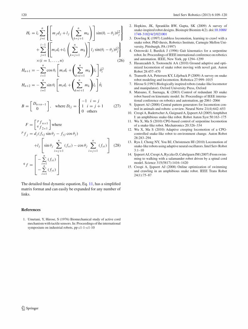
The detailed final dynamic equation, Eq. 11, has a simplifiedmatrix format and can easily be expanded for any number oflinks.
References
1. Umetani, Y, Hirose, S (1976) Biomechanical study of active cordmechanism with tactile sensors. In: Proceedings of the internationalsymposium on industrial robots, pp c1-1–c1-10
2. Hopkins, JK, Spranklin BW, Gupta, SK (2009) A survey ofsnake-inspired robot designs. Bioinspir Biomim 4(2). doi:10.1088/1748-3182/4/2/021001
3. Dowling K (1997) Limbless locomotion, learning to crawl with asnake robot. PhD thesis, Robotics Institute, Carnegie Mellon Uni-versity, Pittsburgh, PA (1997)
4. Ostrowski J, Burdick J (1996) Gait kinematics for a serpentinerobot. In: Proceedings of IEEE international conference on roboticsand automation. IEEE, New York, pp 1294–1299
5. Hasanzadeh S, Tootoonchi AA (2010) Ground adaptive and opti-mized locomotion of snake robot moving with novel gait. AutonRobot 28:457–470
6. Transeth AA, Pettersen KY, Liljeback P (2009) A survey on snakerobot modeling and locomotion. Robotica 27:999–1015
7. Hirose S (1993) Biologically inspired robots (snake-like locomotorand manipulator). Oxford University Press, Oxford
8. Matsuno, F, Suenaga, K (2003) Control of redundant 3D snakerobot based on kinematic model. In: Proceedings of IEEE interna-tional conference on robotics and automation, pp 2061–2066
9. Ijspeert AJ (2008) Central pattern generators for locomotion con-trol in animals and robots: a review. Neural Netw 21(4):642–653
10. Crespi A, Badertscher A, Guignard A, Ijspeert AJ (2005) AmphibotI: an amphibious snake-like robot. Robot Auton Syst 50:163–175
11. Wu X, Ma S (2010) CPG-based control of serpentine locomotionof a snake-like robot. Mechatronics 20:326–334
12. Wu X, Ma S (2010) Adaptive creeping locomotion of a CPG-controlled snake-like robot to environment change. Auton Robot28:283–294
13. Ryu J, Chong NY, You BJ, Christensen HI (2010) Locomotion ofsnake-like robots using adaptive neural oscillators. Intel Serv Robot3:1–10
14. Ijspeert AJ, Crespi A, Ryczko D, Cabelguen JM (2007) From swim-ming to walking with a salamander robot driven by a spinal cordmodel. Science 315(5817):1416–1420
15. Crespi A, Ijspeert AJ (2008) Online optimization of swimmingand crawling in an amphibious snake robot. IEEE Trans Robot24(1):75–87
123