development of Φ125 andΦ140 engines meeting the tier4 ... · 2011 vol. 57 no.164 development of...
TRANSCRIPT
2011 VOL. 57 NO.164 Development of Φ125 andΦ140 Engines Meeting the Tier4 Interim Regulation
― 19 ―
Technical Paper
Development of Φ125 andΦ140 Engines Meeting the Tier4 Interim Regulation
Takashi Kato
Hiroshi Ota
Shohei Nagasaka
Φ125 andΦ140 engines have been developed and launched on the market as the Komatsu engine series
meeting the Tier4 Interim emission regulation. Various new technologies, including a post-processing device, are incorporated in the new engines to meet stricter emission regulations, while ensuring equivalent or superior performance, reliability and durability compared with the conventional machines. The background of and main events that took place in the development process, as well as the technical features of the engines, are reported.
Key Words: Diesel Engine, Emission Regulation, Tier4 Interim, post-processing device, Nitrogen Oxides
1. Introduction The diesel engine features high reliability and durability,
wide-ranging output from small to large size and high engine heat efficiency and is widely used in industry as a motive power source. Nevertheless, its impact on the environment and humans has been pointed out and the circumstances surrounding diesel engines are changing dramatically.
Accordingly, emission regulation governing diesel engines installed in construction machinery have also been reinforced each year worldwide. The regulatory levels centering on the three poles of Japan, the United States and Europe are leading in terms of diesel engine emission regulation for construction and mining machinery.
The Komatsu engine series has been developed and launched as a range of products meeting the EPA Tier4 Interim Emission Regulation of the U.S.A. and Stage IIIB by the EU enforced from January 2011 onward and the construction machinery designation system and off-road emission regulation in Japan enforced from October 2011 (the underlined regulation is hereunder described as “Tier4 Interim emission regulation”). The engine series is already in operation in global construction machinery and mining markets. This paper overviews the medium and large engines developed by Komatsu meeting the Tier4 Interim emission regulation and describes their technical features.
2. Trends of Emission Regulation for
Construction Machinery Engines As mentioned above, from 2011, the new Tier4 Interim
emission regulation has been enforced as emission regulation on diesel engines in construction machinery, ushering in a new
phase. Fig. 1 summarizes the annualized trends of emission
regulation in Japan, the United States and Europe at present. Fig. 2 plots the trends of regulation from Tier1 to Tier2,
Tier3 and Tier4 in terms of the emission regulation values of NOx and PM using the EPA regulation as a representative example. In macroscopic terms, regulatory phases are tightened every 3 to 5 years, while principal regulatory values, e.g. for nitrogen oxides (NOx) and particulate matter (PM), must each be reduced by about 30%. The EPA Tier4 Interim regulation enforced in 2011 requires a reduction to 1/2 in NOx emissions and a reduction to 1/10 in PM emissions, compared with the Tier3 regulation values.
Regulation up to Tier3 could be handled by modifying the engine body. However, the Tier4 Interim emission regulation enforced this time requires drastic reductions, namely a one digit change in the clean levels of emissions and the mounting of a post-processing device.
A measurement mode in steady eight modes called the C1 mode in ISO 08178 has been used as a means of determining the emissions of diesel engines in construction machinery.
A new measurement mode in a transient state known as the non-road transient cycle has been added to the new regulation enforced in 2011. The measurement results of these two modes must be assessed to individually confirm the regulatory values.
Control of various parts with higher precision has become necessary to conform to these new measurement modes.
The methods used to measure the exhaust gas emitted by construction machinery engines are shown in Fig. 3.

2011 VOL. 57 NO.164 Development of Φ125 andΦ140 Engines Meeting the Tier4 Interim Regulation
― 20 ―
Fig. 1 Worldwide emission legislations
Fig. 2 History of NOx and PM emission levels
Fig. 3 Methods to measure exhaust gas emitted by engines in
construction machinery
3.1 Overview of the Φ125 and Φ140 Engine Series
meeting the Tier4 Interim Emission Regulation Komatsu is currently developing, manufacturing and selling
industrial diesel engines ranging from 3.3 to 78 liters. As mentioned earlier, new emission regulation has been and will be enforced in 2011 and 2012 in three poles, namely Japan, the United States and Europe. This paper describes the Φ125 and Φ140 engines (11.0 and 15.2 liters) that are medium and large engines in the 560kW and less category, which meet the Tier4 Interim emission regulation developed in conjunction with the enforcement of these regulations.
Fig. 4 plots the displacements and outputs of the Komatsu engine series.
Fig. 4 Komatsu engine series
3.2 Development Objectives of the Tier4 Interim Engine
Series 1) Conformance with the Tier4 Interim emission regulation of
Japan, the United States and Europe 2) Engine performance (output and fuel consumption)
equivalent or superior to conventional engines 3) Assurance of reliability and durability withstanding a
rugged environment and usage as engines in construction machinery
Fig. 5 summarizes the principal technologies incorporated to achieve the development objectives.
In the history of this development work, the new development of post-processing device was a considerable hurdle. In addition, higher pressure for an electronically controlled high-pressure common rail system, the development of Komatsu Variable Geometry Turbo (KVGT), high precision in the control of an Exhaust Gas Recirculation (EGR) valve, a high capacity EGR cooler, the use of Komatsu Closed Crankcase Ventilation (KCCV) to return blowby gas into suction without releasing it into the atmosphere and other technologies were incorporated into this engine series.
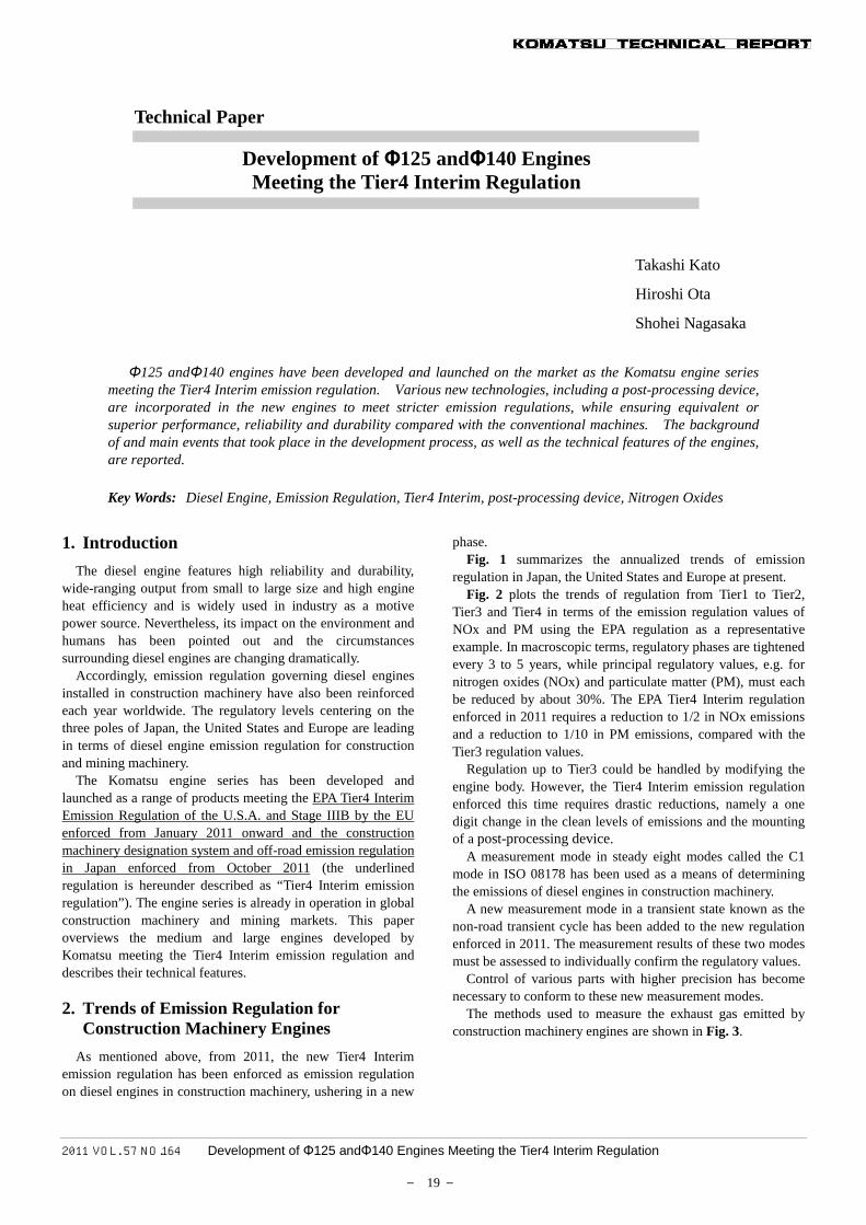
Figs. 6 and 7 illustrate appearances of the 11.0 liters Φ125 and 15.2 liters Φ140 engines, respectively.
Engine Model unit SAA6D125E-5 SAA6D140E-5 SAA6D125E-6 SAA6D140E-6
Cylinders --Bore x Stroke mm 125x150 140x165 125x150 140x165
Displacement L 11.04 15.24 11.04 15.24
Fuel Injection System --Max. Injection Pressure MPa 140 140-160 180 200
Combustion Chamber --Turbo Charger --
EGR --Controller --
Blowby Gas --Post-processing device --
Equipped Equipped (EGR cooler capacity increased)
Reentrant Two-stage combustion chamber (TSCC)Fixed
Release into the atmosphereNot equipped Equipped (KDPF)
Komatsu Closed Crankcase Ventilation (KCCV)
Variable (KVGT)
Tier3 Tier4Interim
6
Common rail system
Electronic control
Fig. 5 Principal technologies incorporated into the Φ125 and
Φ140 engine series
NOx / PM , *NOx+NMHC / PM , **NOx+HC / PM (g/KWh)kW 2004 2005 2009 2010 2011 2012 2015 2016
19…<37
37…<56
56…<75
75…<130
130…<560
<19 *9.5/0.8
19…<37
37…<56
56…<75
75…<130
130…<560
>560
19…<37
37…<56
56…<75
75…<130
130…<560
Tier1 Tier2 Tier4 final / Stage4
6.0/0.4 4.0/0.038.0/0.80
6.0/0.30
7.0/0.40 4.0/0.3
3.6/0.2 3.3/0.02
3.6/0.17 2.0/0.02
8.0/0.8
6.0/0.25
**7.5/0.6
**4.0/0.3
2006 2007 2008 20142013
4.0/0.025
4.0/0.25 3.3/0.02
0.4/0.02
**4.7/0.025
0.4/0.025
6.0/0.2 **4.0/0.2 2.0/0.025
7.0/0.4 **4.7/0.4
3.3/0.0256.0/0.3
Tier3 / Stage3A Tier4 int/ Stage3B
*4.7/0.03 *7.5/0.4
*4.7/0.3*4.7/0.4
3.4/0.02
3.5/0.1 3.5/0.04
0.4/0.02*6.6/0.3 *4.0/0.3*6.4/0.2 *4.0/0.2 2.0/0.02
*9.2/0.54 *6.4/0.2
*7.5/0.8 *7.5/0.4*7.5/0.6 *7.5/0.3
JAPAN
USA
EU
(Tiers2 and Tier3 show the addition values of NOx and NMHC (non-metallic hydrocarbons)
C1 Mode (Before) Non-road transient cycle (NRTC) - Start of the new regulation added
Φ140 engine series Φ125 engine series
Output range of engines described in this paper
2011 VOL. 57 NO.164 Development of Φ125 andΦ140 Engines Meeting the Tier4 Interim Regulation
― 21 ―
Fig. 6 Tier4 Interim engine SAA6D125E-6
Fig. 7 Tier4 Interim engine SAA6D140E-6
4. Tier4 Interim Engine Technologies
The key components that achieve equivalent or superior engine performance (output and fuel consumption) compared with conventional engines and that meet the development objectives mentioned earlier while conforming to the latest emission regulation of Japan, the United States and Europe by the Tier4 Interim engines developed recently are introduced below.
4.1 Combustion System
To reduce NOx emissions by about half while retaining the current system, the EGR rate must be increased from 10% for Tier3 to 20%, which causes a significant decline in combustion. Deterioration of about twice to Tier3 is unavoidable, especially with PM.
The following two improvements were therefore incorporated into this combustion system technology.
The first is a new system enabling higher pressure and
response based on the electronically controlled common rail injection system throughout the Tier3 engine series.
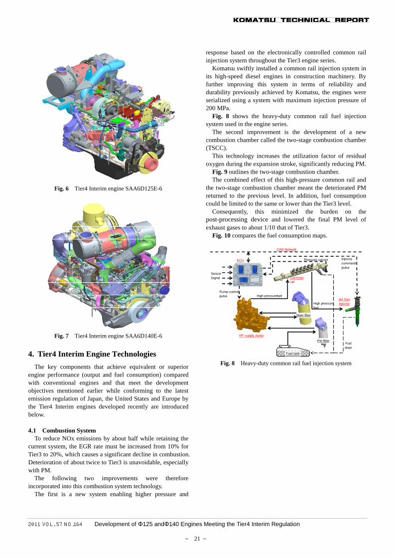
Komatsu swiftly installed a common rail injection system in its high-speed diesel engines in construction machinery. By further improving this system in terms of reliability and durability previously achieved by Komatsu, the engines were serialized using a system with maximum injection pressure of 200 MPa.
Fig. 8 shows the heavy-duty common rail fuel injection system used in the engine series.
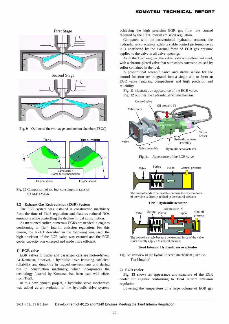
The second improvement is the development of a new combustion chamber called the two-stage combustion chamber (TSCC).
This technology increases the utilization factor of residual oxygen during the expansion stroke, significantly reducing PM.
Fig. 9 outlines the two-stage combustion chamber. The combined effect of this high-pressure common rail and
the two-stage combustion chamber meant the deteriorated PM returned to the previous level. In addition, fuel consumption could be limited to the same or lower than the Tier3 level.
Consequently, this minimized the burden on the post-processing device and lowered the final PM level of exhaust gases to about 1/10 that of Tier3.
Fig. 10 compares the fuel consumption maps.
Fuel tank
Pre filter
Main filter
ECU
Pump controlpulse
Pressure sensor Injectorcommandpulse
CAN Network
HP supply pump
Commonrail
3rd GenInjector
SensorSignal
Fueldrain
High pressurefuel
High pressurefuel
Fig. 8 Heavy-duty common rail fuel injection system
2011 VOL. 57 NO.164 Development of Φ125 andΦ140 Engines Meeting the Tier4 Interim Regulation
― 22 ―
Fig. 9 Outline of the two-stage combustion chamber (TSCC)
Fig. 10 Comparison of the fuel consumption rates of
SAA6D125E-6
4.2 Exhaust Gas Recirculation (EGR) System
The EGR system was installed in construction machinery from the time of Tier3 regulation and features reduced NOx emissions while controlling the decline in fuel consumption.
As mentioned earlier, numerous EGRs are needed in engines conforming to Tier4 Interim emission regulation. For this reason, the KVGT described in the following was used, the high precision of the EGR valve was ensured and the EGR cooler capacity was enlarged and made more efficient. 1) EGR valve
EGR valves in trucks and passenger cars are motor-driven. At Komatsu, however, a hydraulic drive featuring sufficient reliability and durability in rugged environments and during use in construction machinery, which incorporates the technology fostered by Komatsu, has been used with effect from Tier3.
In this development project, a hydraulic servo mechanism was added as an evolution of the hydraulic drive system,
achieving the high precision EGR gas flow rate control required by the Tier4 Interim emission regulation.
Compared with the conventional hydraulic actuator, the hydraulic servo actuator exhibits stable control performance as it is unaffected by the external force of EGR gas pressure applied to the valve in all valve openings.
As in the Tier3 engines, the valve body is stainless cast steel, with a chrome-plated valve that withstands corrosion caused by sulfur contained in the fuel.
A proportional solenoid valve and stroke sensor for the control function are integrated into a single unit to form an EGR valve featuring compactness and high precision and reliability.
Fig. 11 illustrates an appearance of the EGR valve. Fig. 12 outlines the hydraulic servo mechanism.
Fig. 11 Appearance of the EGR valve
Fig. 12 Overview of the hydraulic servo mechanism (Tier3 vs.
Tier4 Interim)
2) EGR cooler
Fig. 13 shows an appearance and structure of the EGR cooler for engines conforming to Tier4 Interim emission regulation.
Lowering the temperature of a large volume of EGR gas
First Stage
Second Stage
Same color = Same fuel consumption
Control valve Oil pressure IN
Valve body
Valve
Valve assembly
Hydraulic actuator assembly
Hydraulic servo actuator
Stroke sensor
Valve
Valve
Spring
Spring Piston
Piston Control pressure
The control tends to be unstable because the external force of the valve is directly applied to the control pressure
Tier3: Hydraulic actuator
Oil pressure IN Spool Control
pressure
The control is stable because the external force of the valve is not directly applied to control pressure
Tier4 Interim: Hydraulic servo actuator
2011 VOL. 57 NO.164 Development of Φ125 andΦ140 Engines Meeting the Tier4 Interim Regulation
― 23 ―
sufficiently is important to drastically reduce NOx emissions but will dramatically increase the heat exchanging capacity required in comparison with that for Tier3.
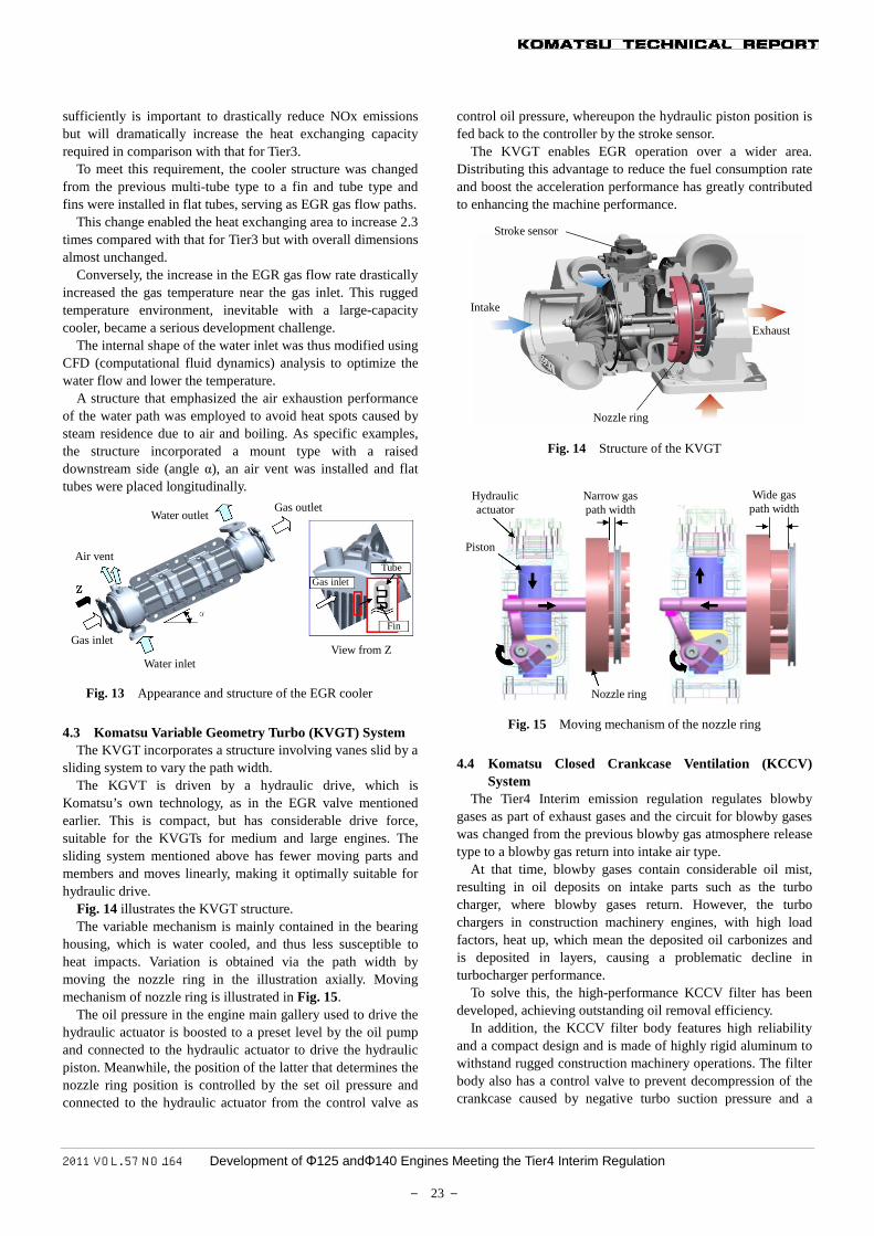
To meet this requirement, the cooler structure was changed from the previous multi-tube type to a fin and tube type and fins were installed in flat tubes, serving as EGR gas flow paths.
This change enabled the heat exchanging area to increase 2.3 times compared with that for Tier3 but with overall dimensions almost unchanged.
Conversely, the increase in the EGR gas flow rate drastically increased the gas temperature near the gas inlet. This rugged temperature environment, inevitable with a large-capacity cooler, became a serious development challenge.
The internal shape of the water inlet was thus modified using CFD (computational fluid dynamics) analysis to optimize the water flow and lower the temperature.
A structure that emphasized the air exhaustion performance of the water path was employed to avoid heat spots caused by steam residence due to air and boiling. As specific examples, the structure incorporated a mount type with a raised downstream side (angle α), an air vent was installed and flat tubes were placed longitudinally.
Fig. 13 Appearance and structure of the EGR cooler
4.3 Komatsu Variable Geometry Turbo (KVGT) System
The KVGT incorporates a structure involving vanes slid by a sliding system to vary the path width.
The KGVT is driven by a hydraulic drive, which is Komatsu’s own technology, as in the EGR valve mentioned earlier. This is compact, but has considerable drive force, suitable for the KVGTs for medium and large engines. The sliding system mentioned above has fewer moving parts and members and moves linearly, making it optimally suitable for hydraulic drive.
Fig. 14 illustrates the KVGT structure. The variable mechanism is mainly contained in the bearing
housing, which is water cooled, and thus less susceptible to heat impacts. Variation is obtained via the path width by moving the nozzle ring in the illustration axially. Moving mechanism of nozzle ring is illustrated in Fig. 15.
The oil pressure in the engine main gallery used to drive the hydraulic actuator is boosted to a preset level by the oil pump and connected to the hydraulic actuator to drive the hydraulic piston. Meanwhile, the position of the latter that determines the nozzle ring position is controlled by the set oil pressure and connected to the hydraulic actuator from the control valve as
control oil pressure, whereupon the hydraulic piston position is fed back to the controller by the stroke sensor.
The KVGT enables EGR operation over a wider area. Distributing this advantage to reduce the fuel consumption rate and boost the acceleration performance has greatly contributed to enhancing the machine performance.
Fig. 14 Structure of the KVGT
Fig. 15 Moving mechanism of the nozzle ring
4.4 Komatsu Closed Crankcase Ventilation (KCCV)
System The Tier4 Interim emission regulation regulates blowby
gases as part of exhaust gases and the circuit for blowby gases was changed from the previous blowby gas atmosphere release type to a blowby gas return into intake air type.
At that time, blowby gases contain considerable oil mist, resulting in oil deposits on intake parts such as the turbo charger, where blowby gases return. However, the turbo chargers in construction machinery engines, with high load factors, heat up, which mean the deposited oil carbonizes and is deposited in layers, causing a problematic decline in turbocharger performance.
To solve this, the high-performance KCCV filter has been developed, achieving outstanding oil removal efficiency.
In addition, the KCCV filter body features high reliability and a compact design and is made of highly rigid aluminum to withstand rugged construction machinery operations. The filter body also has a control valve to prevent decompression of the crankcase caused by negative turbo suction pressure and a
Air vent
Gas inlet
Water inlet
Gas outlet Water outlet
Gas inlet Tube
Fin
View from Z
Stroke sensor
Intake
Exhaust
Nozzle ring
Hydraulic actuator
Narrow gas path width
Wide gas path width
Piston
Nozzle ring
2011 VOL. 57 NO.164 Development of Φ125 andΦ140 Engines Meeting the Tier4 Interim Regulation
― 24 ―
pressure sensor that detects filter clogging. Fig. 16 illustrates an appearance of the KCCV.
Fig. 16 Appearance of the KCCV
4.5 Komatsu Diesel Particulate Filter
The Komatsu Diesel Particulate Filter (KDPF) was developed to drastically reduce particulate matter (PM).
The KDPF also functions as an engine muffler as before and has demonstrated a high noise-reduction effect exceeding 3dB (A) compared with mufflers.
The KDPF was designed to be a system that can continuously burn soot during normal operation as a filter system of the continuous regeneration type by placing an oxide catalyst in the pre-stage of a soot filter with a catalyst. The machine is equipped with a control system of which controller automatically detects deposits of soot in work in a low-temperature environment or during light-load work and forcibly regenerates the filter, suitable for use in various applications.
The KDPF sizes are serialized by selecting those allowing adequate KDPF maintenance intervals, even when deposits of ash (the unburnt portion of exhaust gases) generated by construction machinery operated at a high load factor are taken into consideration.
The connectors of the temperature, pressure and other sensors used in the KDPF control are placed almost centrally in the KDPF to enhance serviceability.
Fig. 17 illustrates the KDPF structure.
Fig. 17 KDPF structure
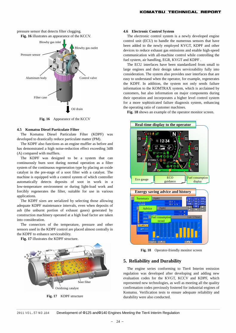
4.6 Electronic Control System The electronic control system is a newly developed engine
control unit (ECU) to handle the numerous sensors that have been added to the newly employed KVGT, KDPF and other devices to reduce exhaust gas emissions and enable high-speed communication with all-machine control while controlling the fuel system, air handling, EGR, KVGT and KDPF .
The ECU interfaces have been standardized from small to large engines and their design takes serviceability fully into consideration. The system also provides user interfaces that are easy to understand when the operator, for example, regenerates the KDPF. In addition, the system not only sends failure information to the KOMTRAX system, which is acclaimed by customers, but also information on major components during their operation and incorporates a higher level control system for a more sophisticated failure diagnosis system, enhancing the operating ratio of customer machines.
Fig. 18 shows an example of the operator monitor screen.
Fig. 18 Operator-friendly monitor screen
5. Reliability and Durability
The engine series conforming to Tier4 Interim emission regulation was developed after developing and adding new evaluation codes for the KVGT, KCCV and KDPF, which represented new technologies, as well as meeting all the quality confirmation codes previously fostered for industrial engines of Komatsu. Verification tests to ensure adequate reliability and durability were also conducted.
Summary
Energy saving advice and history
Advice
Fuel consumption record
[Split]
[Split]
Last 12 hours
Blowby gas inlet
Pressure sensor
Aluminum body
Filter case
Blowby gas outlet
Control valve
Oil drain
Oxidizing catalyst
Soot filter
Real-time display to the operator
Eco gauge ECO guidance
Fuel consumption display

2011 VOL. 57 NO.164 Development of Φ125 andΦ140 Engines Meeting the Tier4 Interim Regulation
― 25 ―
One problem involved the susceptibility of the KVGT to the impacts of oil while using oil pressure as a drive means to ensure high reliability. Quality was therefore enhanced by thoroughly testing it in a rugged environment, e.g. via low-temperature and oil contamination tests.
Furthermore, an important KVGT quality assurance criterion was high reliability to high-cycle fatigue fracture. Construction machinery often experience operations in which the load varies instantaneously. Depending on how the KVGT is controlled, the expansion ratio (ratio between the turbine inlet and outlet pressures) sometimes becomes very high. Such conditions are liable to generate high-cycle fatigue fracture, hence the design was made to withstand these conditions and thorough evaluation tests were conducted.
A long idling test of the KCCV in a low-temperature environment showed freezing of the KCCV piping. Parts of the KCCV that were exposed to this problem were supplied with engine cooling water, while other measures were also taken to solve this problem.
Prior to the use of the KDPF, vibration and shock accelerations in the KDPF mount positions of all construction machinery applications installed in the KDPF were evaluated, and the conditions covering these items were made design conditions. A large vibration test machine was used in evaluation tests and unit vibration tests were conducted in a high-temperature environment. To verify the stable function of the KDPF system in various construction machinery applications, the soot deposit condition was verified under typical usage conditions anticipated in wide-ranging applications. Thorough verification tests were conducted in setting control parameters that did not result in abnormal combustion during active regeneration.
Bench endurance tests were implemented for more than 10,000 hours for each of the Φ125 and Φ140 engines, while machine field tests were also conducted for more than 5,000 hours, to adequately verify the durability of the KCCV.
6. Conclusion
The features and emission-reduction technologies of the newly developed diesel engines in construction machinery meeting the Tier4 Interim emission regulation were described.
Almost all the key components meeting the Tier4 Interim regulation were developed in house and many were also produced in house, to be tailored to the market needs required of construction machinery and differentiate the new engines from competitor’s products, thereby enabling the launch of the engine series meeting the Tier4 Interim regulation. In addition, whole machine could be refined to achieve low fuel consumption, as a feature of Komatsu, and environmental friendliness.
A color multi-monitor is installed as a standard specification and used for regeneration of the KDPF, to notify the operator in the event of failure and for functions such as fuel saving guidance, to make machines that are user friendly and fit the Tier4 era.
An effort will be made to develop technologies that will
contribute to total cost reduction for users in combination with the sophisticated control system by the KOMTRAX system.
[References] “Introduction to New Technologies including ICT and of Applied Fields” 6. Technologies to Meet Exhaust Gas Regulation of Japan, the
United States and Europe Introduction of the writers
Takashi Kato Entered Komatsu in 1994. Currently assigned to the Engine Development Group, Industrial Power Alliance, Ltd.
Hiroshi Ota Entered Komatsu in 1981. Currently assigned to the Engine Development Group, Industrial Power Alliance, Ltd.
Shohei Nagasaka Entered Komatsu in 1996. Currently assigned to the After-Treatment Research and Development Group, Industrial Power Alliance, Ltd.
[A few words from the writers]
Technology to meet exhaust gas regulation for diesel engines is advancing daily and efforts to develop engines to meet the Tier1, Tier2, Tier3 and Tier4 requirements continue. Engines meeting the Tier4 Interim regulation were produced on a wide scale and the writers felt relieved, but this was short-lived. An all-out effort is now underway to develop engines that meet the final Tier4 standard. Where will regulations move after the Tier4 Final? This question remains.