develop a linear measurement sensor system ang...
TRANSCRIPT

DEVELOP A LINEAR MEASUREMENT SENSOR SYSTEM
ANG SEI QI
This Report Is Submitted In Partial Fulfillment Of The Requirement For The Bachelor Degree Of Electronic Engineering (Industrial Electronic)
Faculty of Electronic and Computer Engineering
University Teknikal Malaysia Melaka
April 2010

ii
UNIVERSTI TEKNIKAL MALAYSIA MELAKA
FAKULTI KEJURUTERAAN ELEKTRONIK DAN KEJURUTERAAN KOMPUTER
BORANG PENGESAHAN STATUS LAPORAN
PROJEK SARJANA MUDA II
Tajuk Projek : Develop a Linear Measurement Sensor System
Sesi Pengajian : 2009/2010
Saya ANG SEI QI mengaku membenarkan Laporan Projek Sarjana Muda ini disimpan di Perpustakaan dengan syarat-syarat kegunaan seperti berikut: 1. Laporan adalah hakmilik Universiti Teknikal Malaysia Melaka. 2. Perpustakaan dibenarkan membuat salinan untuk tujuan pengajian sahaja. 3. Perpustakaan dibenarkan membuat salinan laporan ini sebagai bahan pertukaran antara institusi
pengajian tinggi. 4. Sila tandakan ( √ ) :
SULIT*
(Mengandungi maklumat yang berdarjah keselamatan atau kepentingan Malaysia seperti yang termaktub di dalam AKTA RAHSIA RASMI 1972)
TERHAD*
(Mengandungi maklumat terhad yang telah ditentukan oleh organisasi/badan di mana penyelidikan dijalankan)
TIDAK TERHAD
Disahkan oleh:
__________________________ ___________________________________
(TANDATANGAN PENULIS) (COP DAN TANDATANGAN PENYELIA)
Alamat Tetap: 5-05 Lorong Bulan 1,
Pangsapuri Seri Orkid,
13000 Butterworth, P.Pinang.
Tarikh:
Tarikh:

iii
“I hereby declare that this report is the result of my own work except for quotes as cited in the references.”
Signature :……………………….
Author :……………………….
Date :……………………….

iv
“I hereby declare that I have read this report and in my opinion this report is sufficient in
terms of the scope and quality for the award of bachelor of Electronic Engineering
(Industrial Electronics) With Honours.”
Signature :
Supervisor’s Name : MR. FARID ARAFAT BIN AZIDIN
Date :

v
Dedicated to my beloved family especially my father and mother, lecturer, and also to all my friends
vi
ACKNOWLEDGEMENT
First and foremost, I would like to praise God for His blessing. He gave me physical and mental strength to carry on my final year project up to this status.
I would like to express gratitude and thanks to my supervisor, Mr. Farid Arafat Bin Azidin for his support and unfailing patience throughout the duration of the project. His encouragement and guidance are truly appreciated. I have learnt a lot under his guidance, be it practically or theoretically.
Other than that, I am grateful to my all friends who help me and giving me opinion along implementation of this project.
I would like to thanks my parent on their moral support as I can count on them whenever I am upset or down.
Finally, I would like to offer thanks and deepest gratitude from the bottom of my heart for all the support, encouragement and inspirations I obtained throughout the duration of this project. The help rendered to me priceless, be it from the smallest of its kind to the largest.

vii
ABSTRACT
Linear measurement sensor system is a created to measure the linear distance, by
using the reflective infrared system which controlled by PIC16F628A, and display result
on the screen of the LCD. A combination of reflective IR sensor, 2X8 LCD and PIC
controller, the reflective infrared sensor will detect black and white color in the roller,
and give small differences voltage signal, then the small voltage signal will be converted
by into linear measurement in mm. the output signal will be displayed in LCD 2x8. The
PIC will be programmed by using PIC complier software. The 2x8 LCD display is used
and this project will become small, easily to carry. The objective of this system is to
investigate new measurement tools of linear distance that can avoid error occur when
taking the measurement reading, this linear measurement sensor system is introduced to
provide a more accurate linear measured reading. In addition, to shorten time taking of
the reading after a measurement, by just looking at the 2x8 LCD display. To achieve the
objectives, the Protues software is used in the schematic circuit design and simulation,
and the MicroCode Studio software is used in the PicBasic programming development.
The feature of this project is specified by stated the scope of the project. The PIC
programming will be developed for converting the small voltage signal to linear
measurement in mm. The measurement range will be around 0 – 9999mm and show on
the LCD display. Furthermore, the precision of the project can also be stated in the
designing of the black and white roller. This system will be extremely handy and
convenience to operate at different environment condition with the special casing design
to protect the circuit.

viii
ABSTRAK
Sistem sensor pengukuran lurus yang dibuat untuk mengukur jarak lurus, dengan
menggunakan sistem inframerah reflektif yang dikendalikan oleh PIC16F628A, dan
hasilnya dipaparkan pada skrin LCD. Kombinasi sensor IR reflektif, 2X8 LCD dan
controller PIC, sensor inframerah reflektif akan mengesan warna hitam dan putih di
roller, dan memberikan perbezaan kecil isyarat voltan, maka tegangan isyarat kecil akan
dikonversi kedalam pengukuran lurus dalam mm. isyarat keluaran akan dipaparkan di
LCD 2X8. PIC akan diprogram dengan menggunakan “software compiler” PIC. Layar
LCD 2X8 digunakan dan projek ini akan menjadi kecil, mudah untuk dibawa. Tujuan
dari sistem ini adalah untuk mengetahui alat ukur baru jarak lurus yang boleh
mengelakkan kesalahan terjadi saat memuat pembacaan pengukuran, sistem pengukuran
garis lurus sensor diperkenalkan untuk memberikan yang lebih tepat membaca lurus
diukur. Selain itu, untuk memendekkan masa turun membaca selepas pengukuran,
dengan hanya melihat layar LCD 2X8. Untuk mencapai tujuan, Protues perisian yang
digunakan dalam desain skema litar dan simulasi, dan microcode Studio adalah software
yang digunakan dalam pembangunan program PicBasic. Ciri-ciri dari projek ini adalah
ditentukan oleh lingkup projek lain. Pemprograman PIC akan dikembangkan untuk
menukar isyarat voltan kecil untuk pengukuran lurus dalam mm. Rentang pengukuran
akan sekitar 0 – 9999mm dan menunjukkan pada paparan LCD. Selain itu, ketepatan
projek juga boleh dinyatakan dalam perancangan roda hitam dan putih. Sistem ini akan
sangat berguna dan kemudahan untuk beroperasi pada keadaan persekitaran yang
berbeza dengan kotak rekaan khusus untuk melindungi litar.
ix
TABLE OF CONTENTS
CHAPTER TITLE PAGE
PROJECT TITLE i
BORANG PENGESAHAN STATUS LAPORAN ii
STUDENT DECLARATION iii
SUPERVISOR DECLARATION iv
DEDICATION v
ACKNOWLEGEMENT vi
ABSTRACT vii
ABSTRAK viii
TABLE OF CONTENTS ix
LIST OF TABLES xiii
LIST OF FIGURES xiv
LIST OF ABBREVIATION xvi
LIST OF APPENDIX xviii
I INTRODUCTION
x
1.1 Introduction 1
1.2 Objectives 3
1.3 Problem Statement 4
1.4 Scopes of Project 4
1.5 Briefly Explanation of Methodology 5
1.6 Report Structure 7
II LITERATURE REVIEW
2.1 Introduction 8
2.2 Peripherals Interface Controller (PIC) 9
2.2.1 Introduction of PIC 9
2.2.2 Comparison PIC16F628A to Other PIC 11
2.2.3 Benefit of 16F628A 13
2.3 Infrared Sensor 13
2.3.1 Introduction of Infrared Sensor 13
2.3.2 Reflective IR sensor 14
2.3.3 Advantages of Reflective Infrared Sensor 16
2.4 Liquid Crystal Display (LCD) 17
2.4.1 Introduction 17
2.4.2 Three Control Lines of LCD 19
2.4.3 Liquid Crystal Display Pin Description 20
2.5 PICBASIC PRO 20

xi
III PROJECT METHODOLOGY
3.1 Introduction 22
3.2 Flow Chart 23
3.3 PicBasic Programming Flow Chart 26
3.4 System Block Diagram 27
3.5 Circuit Design 27
3.5.1 Voltage Regulator Circuit 28
3.5.2 Main Functional Circuit 28
3.5.3 List of Component 31
3.6 Circuit Simulation 32
3.6.1 Circuit Construct Using Protues ISIS 33
3.6.2 Testing the Programming in ISIS 37
3.7 Test Board Construction 39
3.7.1 Soldering Skills 39
3.7.2 Desoldering Skills 41
3.8 PIC Programming 41
3.8.1 Steps of LCD Programming 42
3.9 PIC Pro Basic Programming Compiling 43
3.10 Circuit Testing 46
3.11 PCB (Printed Circuit Board) Design 46
3.11.1 PCB Layout Design 47
3.12 Casing Design 48

xii
IV RESULT AND DISCUSSION
4.1 Introduction 50
4.2 Software Development Analysis 50
4.2.1 Main Functional Circuit Simulation 50
4.2.2 PCB Layout Design 53
4.2.3 PIC Programming 53
4.3 Hardware Development Analysis 56
4.3.1 Test Board 56
4.3.2 PCB (Printed Circuit Board) 57
4.3.3 Final Product with Casing 58
4.4 Measurement Result Analysis 60
4.4.1 Linear Measurement 60
4.4.2 Curve Line Measurement 61
4.4.3 Circle Measurement 62
V CONCLUSION AND SUGGESTION
5.1 Conclusion 63
5.2 Suggestion 64
REFERENCES 65
xiii
LIST OF TABLES
NO TITLE PAGE
Table 2.1: Comparison between PIC16F628A and PIC16F84 11
Table 2.2: Comparison between PIC16F628A and PIC 16F877 12
Table 2.3: LCD Pin Description 20
Table 3.1: PIC 16F628A pin connection 29
Table 3.2: 2X8 LCD Pin Connection 30
Table 3.3: Component List of Voltage Regulator Circuit 31
Table 3.4: Components List of Main Functional Circuit 31
Table 3.5: Soldering Reminder and Warning 40
Table 3.6: Command Operation 43
Table 4.1: Result Analysis of Linear Measurement 60
Table 4.2: Result Analysis of Curve Line Measurement 61
Table 4.3: Result Analysis of Circle Measurement 62

xiv
LIST OF FIGURES
NO TITLE PAGE
Figure 1.1: Carpenter’s Folding Rule and Metal Tape Measure 2
Figure 1.2: System Block Diagram 3
Figure 1.3: Flow Chart 6
Figure 2.1: Size Comparison 10
Figure 2.2: The Operation Diagram of Reflective Infrared Sensor 15
Figure 2.3: Construction of the LCD 17
Figure 2.4: Character 2X8 LCD 19
Figure 3.1: Flow Chart 23
Figure 3.2: PicBasic Programming Flow Chart 26
Figure 3.3: System Block Diagram 27
Figure 3.4: Voltage Regulator Circuit 28
Figure 3.5: Protues ISIS user’s interface 32
Figure 3.6: Step of Component selection 33
Figure 3.7: Pick Devices Window 33
Figure 3.8: Placing Component on the schematic sheet 34
Figure 3.9: Component Rotation 34
Figure 3.10: Wiring 35
Figure 3.11: Power Supply and Ground 35
Figure 3.12: Edit Terminal Label 36
Figure 3.13: Completed Schematic Circuit 36

xv
Figure 3.14: Circuit Execution/Simulation 37
Figure 3.15: Simulation Error Log 37
Figure 3.16: Constructed Circuit in ISIS Protues 38
Figure 3.17: Programming Compiling 44
Figure 3.18: Program Loader 45
Figure 3.19: MicroCode Loader 45
Figure 3.20: ARES Professional Window 47
Figure 3.21: Route size selection and Miter Selection 48
Figure 3.22: Side View & Front View 49
Figure 4.1: System Description Shown 51
Figure 4.2: LCD Display 51
Figure 4.3: Clock Pulse Supply 52
Figure 4.4: Memory Button 52
Figure 4.5: PCB Layout Bottom View and Top View 53
Figure 4.6: Testing Board 57
Figure 4.7: Finished PCB: Bottom View and Top View (Components Align) 57
Figure 4.8: Top View of Final product 59
Figure 4.9: Bottom View 59
Figure 4.10: Side View 60

xvi
LIST OF ABBREVIATION
PIC - Programmable Interface Controller
LCD - Liquid Crystal Display
IEEE - Institute of Electrical and Electronics Engineers
PSM - Projek Sarjana Muda
CPU - Central Processing Unit
ROM - Read-Only Memory
I/O - Input/Output
RISC - Reduced Instruction Set Computer
EPROM - Erasable Programmable Read-Only Memory
UART - Universal Asynchronous Receiver/Transmitter
PWM - Pulse Width Modulation
RAM - Random-Access-Memory
EEPROM - Electrically Erasable Programmable Read Only Memory
IDCC - Integrated Data Communications Controller
DVI - Digital Visual Interface
VGA - Video Graphics Array

xvii
MCU - Microcontroller Unit
EN - Encoder
PCB - Printed Circuit Board

xviii
LIST OF APPENDIX
NO TITLE PAGE
A Data Sheet of PIC 16F628A 67
B Data Sheet of 7805 5V Voltage Regulator 78
C Data Sheet of 2X8 LCD Monitor 87
D Data Sheet of QRD 1113 90

CHAPTER I
INTRODUCTION
This chapter will give reader a basic introduction to how the idea of this project
generated. The chapter contains introduction, objective of the project, problem statement,
scopes of project, brief methodology, and report structure.
1.1 Introduction
Linear measure is used to express distance and to indicate the differences in their
elevations. The standard units of linear measure are the foot and the meter. In surveying
operations, both of these standard units are frequently divided into tenths, hundredths,
and thousandths for measurements. For longer distances are involved; the foot is
expanded into a statute or to a nautical mile and the meter into a kilometer. But for the
short distance or short range measurement, normally will use centimeter (cm) as a unit. 1
meter is equal to 100 centimeter.
Measuring instruments similar in function to rulers are made portable by folding
(carpenter's folding rule) or retracting into a coil (metal tape measure) when not in use.
When extended for use they are straight, like a ruler. Although both of these

2
measurement tools, can be folder or retracts, nevertheless, the long scale of these
measurement tools have bring a lot of inconveniences for the user.
Figure 1.1: carpenter’s folding rule and metal tape measure
Digital measuring tools seem to be a great idea and new trend in the measurement
world. There is no tape or scale to deal with. But with a digital measuring tape it have to
holding both ends of the tape measure and the tape measure bending and giving an
inaccurate reading. Digital measuring tools accuracy with an old fashion measuring tools
there were so many ways to make the reading inaccurate. With the combination of
electronic technology, the reading can also be memorized by using the digital
measurement tools, to avoid the user in forgetting the reading. The character LCD also is
a trend in the developing measurement tools.
This project title is “Develop a linear measurement sensor system”. A measurement
tool will be developed to measure linear distance. A combination of reflective infrared
sensor and PIC controller, the reflective infrared sensor will detect black and white color
in the roller, and give small differences voltage signal, through the programmed PIC,
then the small voltage signal will be converted by into linear measurement in unit cm.
The output reading will send from the PIC to display on the 2X8 character LCD. The
PIC will be programmed by using PIC complier software Microcode Studio in the form
of PIC Basic language. The 2x8 LCD display is used and this project, so that this project
produces in small, easily to carry. The circuit board cover with a special designed casing
which can move smoothly with the roller stated above and suitable to be use in different
condition.

3
Figure 1.2: System Block Diagram
1.2 Objectives
The main purpose of this project is to develop a linear measurement sensor system
with three main electronic components, which is reflective infrared sensor, PIC and
character LCD display. Therefore the objectives below should be achieved.
1.2.1 To avoid error occur when taking the measurement reading, this linear
measurement sensor system is introduced to provide a more accurate linear
measured reading.
1.2.2 To apply electronic technology and to investigate new measurement tools of
linear distance.
1.2.3 To shorten time taking of the reading after a measurement, by just looking at the
2x8 LCD display.
1.2.4 To explore the programming of PIC controller by using PIC Pro Basic for
distance measurement application.
1.2.5 To explore the application of infrared sensor in industry and to design a
prototype using infrared sensor.

4
1.3 Problem Statement
1.3.1 There will be some error occur when taking the reading from measurement tools,
such as parallax error.
1.3.2 For someone who is not familiar to the measurement tools, they may take time to
take the reading from the scale of the measurement tools.
1.3.3 Old fashion measurement device cannot memorize the reading.
1.3.4 Some measurement tools may not suitable to measure curve line.
1.3.5 The measurement tools may be suitable to use on any kind of surfaces.
1.3.6 Others problem may be faced in this project are to write a programming to
generate the output reading according the range had been stated.
1.4 Scopes of Project
1.4.1 Write the PIC programming for converting the small voltage signal to linear
measurement in cm. The measurement range will be around 0 – 9999mm and
show on the LCD display.
1.4.2 Design the sensor system circuit board with a 5V voltage regulator.
i. PIC controller (PIC 16F628A) with input voltage 5V,
ii. Reflective infrared sensor with input current 100µA – 10mA.
iii. 2x8 LCD display with input voltage 5V.
iv. Push button as a memory button.
v. Other components such as, resistors, power switch, and etc.
1.4.3 The rubber roller will be used and the black-white will be colored inside the
roller for determining the precision of the measurement.
1.4.4 Design a casing that can use to protect the circuit board, and can be use under
different condition.

5
1.5 Briefly Explanation of Methodology
First of all, this project is beginning by having a discussion with supervisor about the
general ideas and concepts that would be used in this project. Next, for literature review
stage, the background of this project is studied and research is done by referring various
sources like: reference book, I.E.E.E journals, website of Labcenter (Proteus Software
Company), and the datasheet. For the following stage, all the information related to
components, PIC, infrared sensor, character LCD display information is searching, and
the most suitable would be selected for used in this project.
On next stage, the PIC Basic programming is studied, and the schematic circuit is
designed and simulated in the Proteus software before construct on the stripboard. If the
functional testing of the circuit on the stripboard is successfully, then will proceed to the
PCB layout design, to produce an as small as possible circuit. Lastly, the casing design
is start; the design must be suitable for protecting the circuit board and fit all
components, to make the project function at any condition. If the outputs of this system
fulfill the project requirements and specification, so this project is considered success. If
the output of this system did not fulfill the desired output, so the troubleshooting would
be carrying out until it reaches the project requirements.
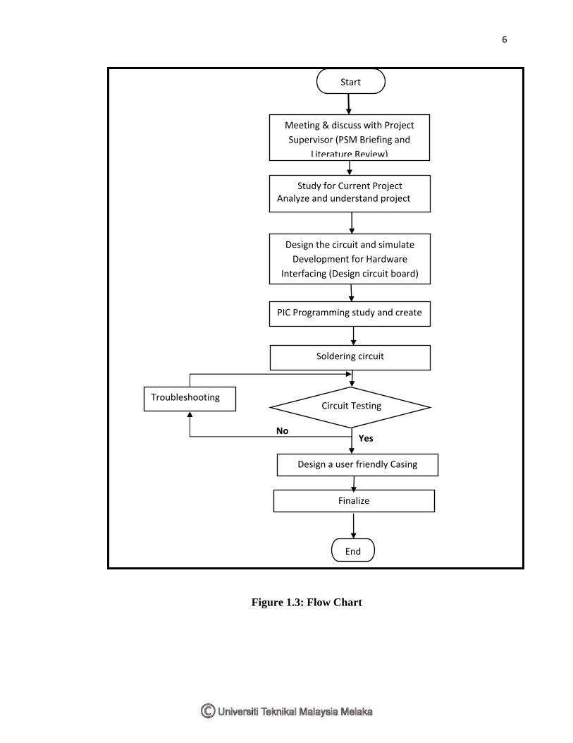
6
Figure 1.3: Flow Chart
YesNo
Design the circuit and simulate
Development for Hardware
Interfacing (Design circuit board)
Circuit Testing
Design a user friendly Casing
End
Study for Current Project Analyze and understand project
PIC Programming study and create
Start
Meeting & discuss with Project
Supervisor (PSM Briefing and
Literature Review)
Soldering circuit
Troubleshooting
Finalize