detection of cracks in rotor based on the 2x and 3x super
TRANSCRIPT

HAL Id: hal-00322889https://hal.archives-ouvertes.fr/hal-00322889
Submitted on 8 Feb 2013
HAL is a multi-disciplinary open accessarchive for the deposit and dissemination of sci-entific research documents, whether they are pub-lished or not. The documents may come fromteaching and research institutions in France orabroad, or from public or private research centers.
L’archive ouverte pluridisciplinaire HAL, estdestinée au dépôt et à la diffusion de documentsscientifiques de niveau recherche, publiés ou non,émanant des établissements d’enseignement et derecherche français ou étrangers, des laboratoirespublics ou privés.
Detection of cracks in rotor based on the 2X and 3Xsuper-harmonic frequency components and the
crack-unbalance interactionsJean-Jacques Sinou
To cite this version:Jean-Jacques Sinou. Detection of cracks in rotor based on the 2X and 3X super-harmonic frequencycomponents and the crack-unbalance interactions. Communications in Nonlinear Science and Numer-ical Simulation, Elsevier, 2008, 13, pp.2024-2040. �10.1016/j.cnsns.2007.04.008�. �hal-00322889�

J-J. Sinou
Detection of cracks in rotor based on the 2× and 3× super-harmonicfrequency components and the crack-unbalance interactions
Jean-Jacques Sinou
Laboratoire de Tribologie et Dynamique des Systemes UMR-CNRS 5513Ecole Centrale de Lyon, 36 avenue Guy de Collongue
69134 Ecully Cedex, Franceemail: [email protected]
Abstract
The purpose of this paper is to investigate the use of the2× and3× super-harmonic components fordetecting the presence of a single transverse breathing crack in a non-linear rotor system. This procedureis based on the detection of the super-harmonic components of the non-linear dynamical behaviour at theassociated sub-critical resonant peaks.The non-linear behaviour of the rotor system with a breathing crack is briefly analysed numerically: itwill be illustrated that the effects of the crack size and location induce the variation of non-linear re-sponses and the emerging of new resonance - antiresonance peaks of the cracked rotor at second, thirdand fourth harmonic component. Then, the influence of the crack-unbalance interactions and more par-ticularly the relative orientation between the front crackand the unbalance are also undertaken withconsiderations of various crack depths, and unbalance magnitudes. It is demonstrated that for a givencrack depth, the unbalance does not only affect the vibration amplitude of the1× amplitudes, but alsothe 1
2and 1
3sub-critical resonant peaks. Finally, it is illustrated that the emerging of super-harmonic
components provides useful information on the presence of crack and may be used on an on-line crackmonitoring rotor system. Using this methodology, the detection of small levels of damage may be easilyundertaken.
Keywords: cracked detection, rotor system, non-linear vibration, super-harmonic components.
1 Introduction
Detection of damage in rotor systems is an important concernto engineering communities. The im-portance of early detection of cracks has led to continuous efforts due to the fact that unpredictableoccurrence of damage may cause catastrophic failure. It is very difficult but also highly desirable topursue effective engineering solutions to detect and locate the damage situation in rotating systems atthe earliest possible stage. Reviews on the dynamical behaviour of rotors with transverse crack werepublished by Wauer [1], Gasch [2] and Dimarogonas [3].During the past several decades, significant amount of research has been conducted in the area of crackdetection in systems using only theoretical modelling method [4–11], combined both theoretical andexperimental methods [12–14] or only experimental method [15]. The main idea of these approachesis that a change in a rotor system due to damage crack will manifest itself as changes in the rotor dy-namic behaviour: first of all, the presence of a transverse crack induces a slight decrease of the naturalfrequencies [2,10,16]. Secondly, resonances appear when the rotational speeds of the shaft reach1
2and
1
3of the critical speeds of the rotor system. Therefore, with the increase of the crack depth, the1
2and
1

J-J. Sinou
1
3sub-critical resonant peaks increase [6, 11, 17]. Finally,some researchers [18] indicated that the shaft
executes two and three loops per shaft revolution at the1
2and 1
3sub-critical speeds, respectively.
In most of the studies for crack detection in rotor systems, researchers used changes in natural frequen-cies and evolution of the non-linear behaviour of the systemat the super-harmonic components as thediagnostic tools. In this paper it will be shown that an appropriate use of the super-harmonic compo-nents may be useful for crack detection in rotor systems. So the present study attempts to propose acomplete analysis of the crack-unbalance interactions on the super-harmonic components at the1
2and 1
3
sub-critical resonant peaks. Numerical example will be conducted on variety of damage location, cracksize and unbalance parameters (magnitude and relative orientation with the front crack) to verify thesuitability of the use of the super-harmonic components in order to detect the presence of a transversecrack in rotor. One of the advantages of the proposed approach is that the emerging of super-harmoniccomponents may be easily undertaken for the detection of a crack in rotating shafts, especially in theearly stage of the damage where the ability to discriminate changes of modal parameters caused by dam-age from those caused by other environmental condition changes is very difficult.The paper is set up as follows: firstly, the description of thenon-linear rotor system and the model-ing of the breathing crack are investigated. Then, the non-linear periodic response of the cracked rotoris undertaken by approximating the non-linear dynamic by truncated Fourier series withm harmonics.Moreover, the state vectors of the complete cracked rotor will be partitioned into subvectors relating tothe Fourier components which are associated with the degrees of freedom at the crack location, and theFourier components which are associated with the others degrees of freedom. Then, the emerging of the2× and3× super-harmonic components for detecting the presence of a crack is investigated. Numericalexamples including various crack parameters (location anddepth) and unbalance parameters (magni-tude and orientation with the crack) are considered in orderto validate the detection of a crack basedon the resonance peaks at the1
2or 1
3sub-critical resonances and the determination of the associated
super-harmonic frequency components.
2 The model of the cracked rotor
In this study, the rotor is composed of a shaft with one disc atthe mid-span, as illustrated in Figure 1.All the values of the physical parameters are given in Table 1.
2.1 Shaft elements
The shaft is discretized into 10 Timoshenko beam finite elements with four degrees of freedoms at eachnode (two lateral displacements and two rotations). At eachnode of the Timoshenko beam finite ele-ments, we have [19,20]
(MeT +Me
R) Xe + (ηKe
B − ωGe) Xe + (KeB + ηωKe
C)Xe = Fe (1)
whereω is the rotational speed.MeT andMe
R, andGe are the translational, rotary mass and gyroscopicmatrices of the shaft element, respectively.Ke
B andKeC are the stiffness and circulatory matrices due to
shaft internal damping.η defines the coefficient of damping that is associated to the modal damping forthe first mode of the system at rest (ω = 0 ). Fe includes the gravitational forces and unbalance forces.
2

J-J. Sinou
2.2 Rigid disc
The rotor system has one disc at the mid-span that is modelledas a rigid disk and may be written as(
MdT +Md
R
)
Xd− ωGdXd = Fd (2)
whereMdT andMd
R are the translational mass and rotary mass matrices respectively. Gd is the gyro-scopic matrix, andFd corresponds to the unbalance and gravitational forces.
Figure 1: Finite-element model of the rotor and the cracked-beam section
Notation Description ValueR radius of the rotor shaft 0.005mL length of the rotor shaft 0.5mRD outer radius of the disk 0.025mhD thickness of the disk 0.015mE Young’s modulus of elasticity 2.1 1011N.m−2
G shear modulus 7.7 1010N.m−2
ρ density 7800kg.m−3
ν Poisson ratio 0.3η coefficient of damping 2 10−5
me mass unbalance 0.001kgde eccentricity of the mass unbalance 0.01mφ relative orientation between the crack and the unbalance 0degreeKs stiffness of supports 2 106N.m−1
ω1, ω2 first double frequency of the uncracked rotor (at rest) 317rad.s−1
ω3, ω4 second double frequency of the uncracked rotor (at rest)1898rad.s−1
Table 1: Value of the physical parameters
3
J-J. Sinou
2.3 Modelling of the breathing crack
2.3.1 The crack model
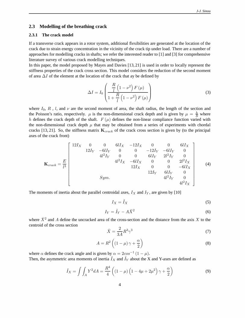
If a transverse crack appears in a rotor system, additional flexibilities are generated at the location of thecrack due to strain energy concentration in the vicinity of the crack tip under load. There are a number ofapproaches for modelling cracks in shafts; we refer the interested reader to [1] and [3] for comprehensiveliterature survey of various crack modelling techniques.In this paper, the model proposed by Mayes and Davies [13, 21]is used in order to locally represent thestiffness properties of the crack cross section. This modelconsiders the reduction of the second momentof area∆I of the element at the location of the crack that ay be defined by
∆I = I0
R
l
(
1− ν2)
F (µ)
1 +R
l
(
1− ν2)
F (µ)
(3)
whereI0, R , l, andν are the second moment of area, the shaft radius, the length ofthe section andthe Poisson’s ratio, respectively.µ is the non-dimensional crack depth and is given byµ = h
Rwhere
h defines the crack depth of the shaft.F (µ) defines the non-linear compliance function varied withthe non-dimensional crack depthµ that may be obtained from a series of experiments with chordalcracks [13, 21]. So, the stiffness matrixKcrack of the crack cross section is given by (to the principalaxes of the crack front)
Kcrack =E
l3
12IX 0 0 6lIX −12IX 0 0 6lIX12IY −6lIY 0 0 −12IY −6lIY 0
4l2IY 0 0 6lIY 2l2IY 04l2IX −6lIX 0 0 2l2IX
12IX 0 0 −6lIX12IY 6lIY 0
Sym. 4l2IY 04l2IX
(4)
The moments of inertia about the parallel centroidal axes,IX andIY , are given by [10]
IX = IX (5)
IY = IY −AX2 (6)
whereX2 andA define the uncracked area of the cross-section and the distance from the axisX to thecentroid of the cross section
X =2
3AR3γ3 (7)
A = R2
(
(1− µ) γ +α
2
)
(8)
whereα defines the crack angle and is given byα = 2cos−1 (1− µ).Then, the asymmetric area moments of inertiaIX andIY about the X and Y-axes are defined as
IX =
∫ ∫
AY 2dA =
R4
4
(
(1− µ)(
1− 4µ+ 2µ2)
γ +α
2
)
(9)
4
J-J. Sinou
IY =
∫ ∫
AX2dA =
πR4
4+R4
(
2
3(1− µ) γ3 +
1
4(1− µ)
(
1− 4µ+ 2µ2)
γ + sin−1 (γ)
)
(10)
whereγ is equal to√
2µ − µ2 for convenience.
2.3.2 The breathing mechanism
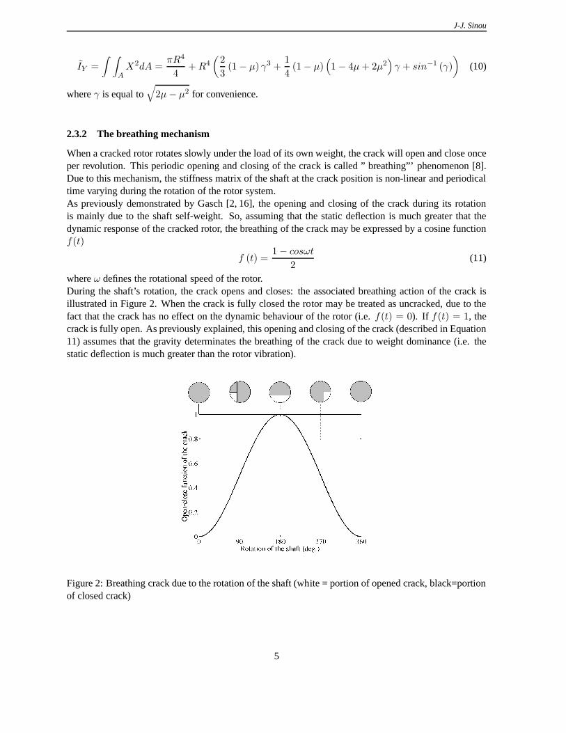
When a cracked rotor rotates slowly under the load of its own weight, the crack will open and close onceper revolution. This periodic opening and closing of the crack is called ” breathing”’ phenomenon [8].Due to this mechanism, the stiffness matrix of the shaft at the crack position is non-linear and periodicaltime varying during the rotation of the rotor system.As previously demonstrated by Gasch [2, 16], the opening andclosing of the crack during its rotationis mainly due to the shaft self-weight. So, assuming that thestatic deflection is much greater that thedynamic response of the cracked rotor, the breathing of the crack may be expressed by a cosine functionf(t)
f (t) =1− cosωt
2(11)
whereω defines the rotational speed of the rotor.During the shaft’s rotation, the crack opens and closes: theassociated breathing action of the crack isillustrated in Figure 2. When the crack is fully closed the rotor may be treated as uncracked, due to thefact that the crack has no effect on the dynamic behaviour of the rotor (i.e.f(t) = 0). If f(t) = 1, thecrack is fully open. As previously explained, this opening and closing of the crack (described in Equation11) assumes that the gravity determinates the breathing of the crack due to weight dominance (i.e. thestatic deflection is much greater than the rotor vibration).
Figure 2: Breathing crack due to the rotation of the shaft (white = portion of opened crack, black=portionof closed crack)
5

J-J. Sinou
2.4 Equation of motion of the cracked rotor
After assembling the different shaft elements, the rigid disc and the discrete bearing stiffness that arelocated at the two ends of the shaft, the equation of motion ofthe complete cracked rotor system in afixed co-ordinate system can be written as
MX+DX+ (K− f (t)Kc)X = Q+W (12)
where overdots indicate differentiation with respect to time. The mass matrixM includes mass matricesof the shaft and rigid disc. The matrixD considers the shaft internal damping, the damping of thesupports and the gyroscopic moments. The matrixK includes the stiffness matrices of the shaft andsupports, and the circulatory matrix due to shaft internal damping.Kc is the stiffness matrix due to thecrack. The terms of this matrix are equal to zero except at thecrack location degree-of-freedom wherethe8 × 8 matrixKcrack is present.Q andW are the vector of gravity and imbalance forces due to thedisk and the shaft, respectively.As previously indicated, the above equations of the crackedrotor have a time-dependent coefficientdue to the fact that the crack breathes when the system rotates. The amount of open part of the crackconstantly varies with the rotation of the shaft, thereby changing the stiffness of the cracked rotor. Theglobal stiffness matrix of the rotor consists of a constant partK and a time dependent partf (t)Kc.
3 Non-linear analysis
3.1 Non-linear responses of the cracked rotor
Due to the time-dependent coefficient of Equation 12, the system of the crack rotor may be rewritten ina ”‘non-linear”’ form as
MX+DX+KX = Q+W + fNL (X, ω, t) (13)
with
fNL (X, ω, t) =1
2(1− cosωt)KcX (14)
In the following the termfNL will be treated as a non-linear term due to its dependence onX thatmakes Equation 13 non-linear. A frequency-domain method such as the harmonic balance methods withcontinuation schemes that are well-known numerical tools,may be applied in order to study non-lineardynamics vibrations in rotating systems [22, 23]. This approach may be used as an alternative to time-domain methods when periodic solutions of the on-linear system exist, and so is a very efficient way ofapproximating the vibration of a cracked rotor. We refer theinterested reader to [22–25] for a survey ofsome recent developments and alternative approaches.The general idea of the harmonic balance method is to represent the periodic solution of the non-linearsystem by its frequency content.So, the non-linear dynamical responses of the cracked rotorsystem are represented as truncated Fourierseries withm harmonics:
X (t) = B0 +m∑
k=1
(Bk cos (kωt) +Ak sin (kωt)) (15)
whereω defines the fundamental frequency.B0, Ak andBk (with k = 1, · · · ,m) define the unknowncoefficients of the finite Fourier series. The number of harmonic coefficientsm is selected on the basis
6

J-J. Sinou
of the number of significant harmonics expected in the non-linear dynamical response.Moreover, the non-linear forcefNL, the gravity forceQ and the global unbalance forceW are repre-sented as truncated Fourier series. First of all, the non-linear force due to the presence of the crackfNL
is approximated by finite Fourier series of orderm
fNL (X, ω, t) = Cf0+
m∑
k=1
(
Cfk cos (kωt) + S
fk sin (kωt)
)
(16)
Then, it may be observed that the unbalance force componentswithout considering the crack (for theshaft and the disk) in the horizontal and vertical directions (Y-direction and X-direction as indicated inFigure 1) are given asmedecos (ωt+ φ) andmedesin (ωt+ φ), respectively.me andde are the massunbalance and the eccentricity for each element of the rotorsystem.φ defines the initial angular positionwith respect to the Z-axis.So, the gravity forceQ and the global unbalance forceW are exactly defined by constant componentsand first-order periodic components in the frequency domain, respectively. We have
Q (X, ω, t) = CQ0
(17)
W (X, ω, t) = CW1 cos (ωt) + SW
1 sin (kωt) (18)
Substituting these last fourth expressions 15, 16, 17 and 18into the rotor equation of motion 13 andbalancing the harmonic terms yields a set of(2m+ 1) ∗ n equations wheren is the number of degree-of-freedom for the complete cracked rotor system.The constant termsB0 that are given by the firstnth relations are given by
KB0 = CQ0+C
f0
(19)
Then, the first harmonic componentsA1 andB1 are determined by resolving the following equations[
K− ω2M −ωDωD K− ω2M
] [
A1
B1
]
=
[
SW1 + S
f1
CW1 +C
f1
]
(20)
Finally, the2m ∗ (n− 1) remaining equations that define thekth Fourier coefficientsAk andBk for2 ≤ k ≤ m are given by
[
K− (kω)2 M −kωD
kωD K− (kω)2 M
] [
Ak
Bk
]
=
[
Sfk
Cfk
]
(21)
The non-linear expressionfNL (X, ω, t) is a function of the non-linear responsesX (t) and the associatedFourier coefficientsB0, Ak andBk (with 1 ≤ k ≤ m). So, the Fourier coefficientsCf
0, Sf
k andCfk
(with 1 ≤ k ≤ m) may be determined fromB0, Ak andBk (with 1 ≤ k ≤ m) by using the followingiteration process, called the Alternate Frequency/Time domain approach (AFT method [26])
[B0 A1 B1 · · · Am Bm]T ⇒ X (t) ⇒ fNL (X, ω, t) ⇒ [C0 S1 C1 · · · Sm Cm]T (22)
Then, the(2m+ 1) ∗ n non-linear equations of motion 19, 20 and 21 can be solved by using a solversuch as the Newton-Raphson method [27].Moreover, a continuation scheme in conjunction with the harmonic balance method and based on thepath following continuation and Lagrangian polynomial extrapolation [10, 28], is used to give a firstapproximation of the Fourier coefficientsB0, Ak andBk (with 1 ≤ k ≤ m) of the cracked rotor systemwhen the rotational speedω increases.
7
J-J. Sinou
3.2 Partition and condensation on the cracked element
The state vectorsAk andBk (for 1 ≤ k ≤ m) are partitioned into subvectors relating to the FouriercomponentsAc
k andBck which are associated with the degrees of freedom at the cracklocation, and the
Fourier componentsAuk andBu
k which are associated with the others degrees of freedom.
Uk =
[
Uck
Uuk
]
=
Ack
Bck
Auk
Buk
= Ψ
[
Ak
Bk
]
(23)
The subscript ‘k’ represents ”‘kth harmonic components”’, the superscript ‘u’ represents ”‘uncracked”’,and the superscript ‘c’ represents ”‘cracked”’.Hence, for the present case (i.e. the rotor system has only one crack), the vectorsAc
k andBck have the
size of8× 1, and the vectorsAuk andBu
k have the size of36× 1. Then, the vectorsUck have the size of
16× 1, and the vectorUuk have the size of72× 1.
Considering Equation 23, Equation 20 and 21 which is associated with the kth harmonic components canbe partitioned as
ΘkUk = Fk (24)
with
Θk =
[
Θcck Θcu
k
Θuck Θuu
k
]
= ΨT
[
K− (kω)2M −kωD
kωD K− (kω)2 M
]
Ψ (25)
Each of the matricesΘk have the size of88×88; Θcck , Θcu
k , Θuck andΘuu
k are16×16, 16×72, 72×16,and72× 72 matrices, respectively.The expressions ofF1 which is associated with the first harmonic components is given by
F1 =
[
Fc1
Fu1
]
=
SW,c1
+ Sf,c1
CW,c1
+Cf,c1
SW,u1
CW,u1
= ΨT
[
SW1 + S
f1
CW1 +C
f1
]
(26)
and the expressions ofFk (for 2 ≤ k ≤ m) which are associated with thekth harmonic components canbe rewritten as
Fk =
[
Fck
Fuk
]
=
[
Fck
0
]
=
Sf,ck
Cf,ck
0
0
= ΨT
[
Sfk
Cfk
]
(27)
The vectorsFk have the size of88 × 1. The vectorsSf,ck , Cf,c
k , SW,c1
andCW,c1
have the size of8 × 1,and the vectorsSW,u
1andCW,u
1have the size of36× 1.
The vectorsFk (for 2 ≤ k ≤ m) represent the excitation due to the presence of the crack. So the vectorFuk is a is a zero vector, as indicated in Equation 27. Moreover, it may be remained that the vectorF1
corresponds not only to the excitation due to the presence ofthe crack, but also to the contribution of theunbalance force: the terms of this vector are zero except at the crack and unbalance locations. SoFu
1
may only contain an unbalance contribution, as indicated inEquation 26.
8

J-J. Sinou
So, considering Equations 23, 24, 25 and 26, Equations 20 that define the first harmonic componentsA1
andB1 can be partitioned as[
Θcc1 Θcu
1
Θuc1 Θuu
1
] [
Uc1
Uu1
]
=
[
Fc1
Fu1
]
(28)
Then, considering 23, 24, 25 and 27, the2m∗(n− 1) Equations 21 that define thekth Fourier coefficientsAk andBk for 2 ≤ k ≤ m may be partitioned as
[
Θcck Θcu
k
Θuck Θuu
k
] [
Uck
Uuk
]
=
[
Fck
0
]
(29)
Finally, considering Equations 28 and 29, the vectorsUc1 andUc
k that correspond to the Fourier compo-nents of the crack element may be determined by solving
Uc1 =
(
Θcc1 −Θcu
1 Θuu−1
1Θuc
1
)
−1 (
Fc1 −Θcu
1 Θuu−1
1Fu1
)
(30)
Uck =
(
Θcck −Θcu
k Θuu−1
k Θuck
)
−1
Fck (31)
Then, the Fourier components vectorsUu1 andUu
k of the uncracked elements are given by
Uu1 = Θuu−1
k Fu1 −Θuu−1
k
(
(
Θcc1 −Θcu
1 Θuu−1
1Θuc
1
)
−1 (
Fc1 −Θcu
1 Θuu−1
1Fu1
)
)
(32)
Uuk = −Θuu−1
k Θuck
(
Θcck −Θcu
k Θuu−1
k Θuck
)
−1
Fck (33)
4 Numerical simulations
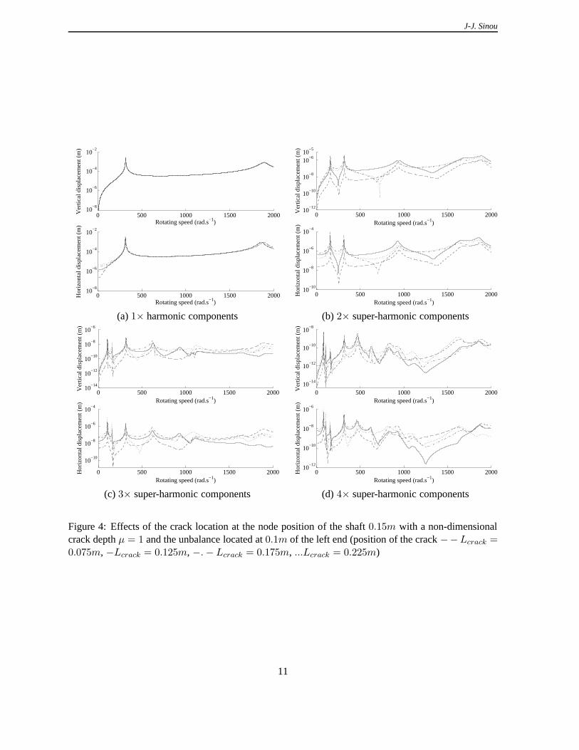
4.1 Effects of the crack size and location
In this section, the main effects of the crack size and location on the non-linear behaviour of the crackedrotor system are briefly summarized.Firstly, Figures 3 illustrate the effects of crack depth on the vertical and horizontal responses correspond-ing to the first harmonic component (see Figure 3(a)), the2× super-harmonic frequency components(see Figure 3(b)), the2× super-harmonic frequency components (see Figure 3(c)), and the4× super-harmonic frequency components (see Figure 3(d)) at the nodeposition of the shaft0.15m. Due to thepresence of the crack, the second harmonic components increase when the rotational speed reaches1
2
and 1 of the critical speeds. The third harmonic components (respectively, fourth harmonic components)increase near the rotational speeds at1
3, 1
2and 1 of the critical speeds (respectively near the rotational
speeds at14, 1
3, 1
2and 1 of the critical speeds). A decrease in the critical speeds of the rotor system due to
the reduction in system stiffness resulting from the presence of the crack is also observed. Moreover, itis clear that the vibration amplitudes of the second, third and fourth harmonic components depend on thecracked depth: with the increase of the crack depth, these harmonic components increase. Consideringthe first harmonic component, the vibration amplitudes of the crack rotor system do not greatly changewith respect to the crack size. However, it may be remind that, for a given crack depth, the first harmoniccomponent of the crack rotor system is associated with the rotor imbalance and the relative position be-tween the crack direction and the imbalance [17].Then, the effects of crack position on the harmonic components of the nonlinear response of the rotor are
9

J-J. Sinou
illustrated in Figures 4. It may be remind that the crack location clearly affect the decrease in the criticalspeeds of the cracked rotor and the vibration amplitudes in the sub-critical resonances [11]. Finally, itmay be observed that antiresonances for the2×, 3× and4× super-harmonic frequency components ofthe cracked rotor system appears due to the presence of the crack. The emerging and location of newantiresonances and the shift in the antiresonances depend on the crack size and location.In conclusion, the variation of non-linear responses and the emerging of new resonance - antiresonancepeaks of the cracked rotor at second, third and fourth harmonic components may provide useful infor-mation on the presence of a crack and may be used on an on-line crack monitoring rotor system.
0 500 1000 1500 200010
−8
10−6
10−4
10−2
Ver
tical
dis
plac
emen
t (m
)
Rotating speed (rad.s−1)
0 500 1000 1500 200010
−8
10−6
10−4
10−2
Hor
izon
tal d
ispl
acem
ent (
m)
Rotating speed (rad.s−1)
0 500 1000 1500 200010
−10
10−8
10−6
10−5
Ver
tical
dis
plac
emen
t (m
)
Rotating speed (rad.s−1)
0 500 1000 1500 200010
−10
10−8
10−6
10−4
Rotating speed (rad.s−1)
Hor
izon
tal d
ispl
acem
ent (
m)
(a)1× harmonic components (b)2× super-harmonic components
0 500 1000 1500 200010
−14
10−12
10−10
10−8
10−6
Rotating speed (rad.s−1)
Ver
tical
dis
plac
emen
t (m
)
0 500 1000 1500 200010
−15
10−10
10−5
Rotating speed (rad.s−1)
Hor
izon
tal d
ispl
acem
ent (
m) 0 500 1000 1500 2000
10−16
10−14
10−12
10−10
10−8
Ver
tical
dis
plac
emen
t (m
)
Rotating speed (rad.s−1)
0 500 1000 1500 200010
−16
10−14
10−12
10−10
10−8
10−6
Rotating speed (rad.s−1)
Hor
izon
tal d
ispl
acem
ent (
m)
(c) 3× super-harmonic components (d)4× super-harmonic components
Figure 3: Effects of the crack size at the node position of theshaft 0.15m with a crack situated atLcrack = 0.175m and the unbalance located at0.1m of the left end (− µ = 1, ... µ = 0.75, −.− µ = 0.5,−− µ = 0.25)
10
J-J. Sinou
0 500 1000 1500 200010
−8
10−6
10−4
10−2
Ver
tical
dis
plac
emen
t (m
)
Rotating speed (rad.s−1)
0 500 1000 1500 200010
−8
10−6
10−4
10−2
Hor
izon
tal d
ispl
acem
ent (
m)
Rotating speed (rad.s−1)
0 500 1000 1500 200010
−12
10−10
10−8
10−6
10−5
Rotating speed (rad.s−1)
Ver
tical
dis
plac
emen
t (m
)0 500 1000 1500 2000
10−10
10−8
10−6
10−4
Rotating speed (rad.s−1)H
oriz
onta
l dis
plac
emen
t (m
)
(a)1× harmonic components (b)2× super-harmonic components
0 500 1000 1500 200010
−14
10−12
10−10
10−8
10−6
Rotating speed (rad.s−1)
Ver
tical
dis
plac
emen
t (m
)
0 500 1000 1500 2000
10−10
10−8
10−6
10−4
Rotating speed (rad.s−1)
Hor
izon
tal d
ispl
acem
ent (
m)
0 500 1000 1500 200010
−14
10−12
10−10
10−8
Rotating speed (rad.s−1)
Ver
tical
dis
plac
emen
t (m
)
0 500 1000 1500 200010
−12
10−10
10−8
10−6
Hor
izon
tal d
ispl
acem
ent (
m)
Rotating speed (rad.s−1)
(c) 3× super-harmonic components (d)4× super-harmonic components
Figure 4: Effects of the crack location at the node position of the shaft0.15m with a non-dimensionalcrack depthµ = 1 and the unbalance located at0.1m of the left end (position of the crack−−Lcrack =0.075m, −Lcrack = 0.125m, −.− Lcrack = 0.175m, ...Lcrack = 0.225m)
11

J-J. Sinou
4.2 Damping and unbalance effects
First of all, it is well known that increasing the rotor unbalance increases the1× amplitudes of thecracked rotor [17]: this fact is indicated in Equations 28 and 20. However, it may be noted that the othern× amplitudes (withn ≥ 2) may also be affected by the rotor imbalance. Figure 5(a) illustrates theevolution of the vibration amplitudes in the1
2sub-critical resonances with the variation of the unbalance
of the cracked rotor. With the increase of the rotor unbalance, the amplitudes at the sub-critical reso-nances increase, due to the interaction of the crack breathing mechanism, gravity and rotor unbalance (asindicated in Equations 29 and 21). Effectively, it may be remained that the amplitudes of the non-linearterms 16 due to the presence of the crack depend on the amplitudes of the rotor’s vertical and horizontaldisplacements (as indicated in Equation 14) and so the rotorunbalance.Moreover, the vibration amplitudes in the1
2sub-critical resonances depend on the damping of the cracked
rotor system, as illustrated in Figure 5(b). With any decrease of damping, the amplitudes increase drasti-cally and the presence of the crack may be clearly detected. However, if the damping of the rotor systemis relatively high, the resonant amplitudes in the1
2sub-critical resonances will disappear due to the fact
that the2× and3× super-harmonic frequency components are suppressed. These informations can beused as indexes for the detection of cracks in the rotor system: if the damping remains constant, increas-ing the unbalance of the rotor system may change and increasethen× amplitudes (withn ≥ 2) whenthe rotor reaches the1
nsub-critical resonances.
However, it is clear that the vibration amplitudes in the1
nsub-critical resonances (withn ≥ 2) depend
not only on the rotor damping, unbalance, position and depthof the crack, but also on the combinationsof the unbalance and the crack parameters. So, the effects ofcrack-unbalance interaction are analysed inthe following section of this paper.
152154
156158
160
0
1
2
3
4
x 10−3
5
10
15
x 10−3
ω (rad/s)Unbalance (kg.m)
Ver
tical
dis
plac
emen
t (m
)
152154
156158
160
0.5
1
1.5
2
x 10−4
2
4
6
8
10
12
x 10−5
ω (rad/s)Damping factor
Ver
tical
dis
plac
emen
t (m
)
(a) Unbalance effect (b) Damping effect
Figure 5: Influence of damping and mass unbalance on the vertical vibration amplitudes around12
sub-critical resonances (withµ = 1, Lcrack = 0.225m) and the unbalance located at0.25m
12

J-J. Sinou
4.3 Effects of the crack-unbalance interaction on the super-harmonic frequency compo-nents
Figures 7 illustrate the second super-harmonic frequency components of the middle of the rotor forvarious crack-unbalance orientations and unbalance in thevertical and horizontal directions. It clearlyappears that the relative orientation angle between the unbalance of the cracked rotor and the crack andtheir interaction drastically affect the evolutions of thesecond super-harmonic frequency component atthe 1
2sub-critical resonances. Then, the evolutions of the1
2sub-critical resonances peak with respect to
the unbalance-crack angle change due to the magnitude of theunbalance in both the vertical and hori-zontal directions (see for example Figures 7(b), (d) and (f)).Therefore, it may be observed that the interaction between the crack and the unbalance may mask thepresence of the crack: effectively, the second super-harmonic frequency component and the resonantamplitudes in the1
2sub-critical resonances may disappear (see for example Figure 7(b) when the angle
of the unbalance is at270 degrees).Figures 6 indicate the evolutions of the third super-harmonic components of the middle of the rotorwhen the rotor reaches the1
3sub-critical resonances. As previously seen for the secondsuper-harmonic
frequency component, depending on the relative angle between unbalance and crack vectors, the thirdsuper-harmonic frequency component can increase or even decrease in vertical and horizontal ampli-tudes. With the decrease of the rotor unbalance, the magnitudes of the super-harmonic frequency compo-nents decrease in the vertical and horizontal directions. If the crack effect is predominant, the magnitudeof the sub-critical resonances peaks does not greatly change, as illustrated in Figures 7(e-f) and 6(e-f).If the crack unbalance is more important than the crack, it iswell known that the the magnitude of thesub-critical resonances peaks is constant as shown in Figure 7(a) for the horizontal direction. However,it may be noted that the associated magnitude of the sub-critical resonances peak slightly changes in thevertical direction: effectively, the highest changes in the stiffness of the crack cross section (see Equation4) occur in the vertical direction due to the orientation of the crack and the shaft self-height. This is whythe sensibility of the magnitudes of1
2and 1
3sub-critical resonances with respect to the unbalance angle
and the unbalance-crack interactions are different in the vertical and horizontal directions.Moreover, the influence of the crack on the non-linear dynamic of the rotor system increases when theunbalance magnitude decreases. In this case, two resonant peaks appear in the horizontal direction duethe coupling between the two bending directions, as indicated in Figure 7(e). With the decrease of theunbalance, the ratio between the first resonance peak (at103rad/s) and the second resonance peak (at105rad/s) decreases (see Figures 7(a), (c) and (e)). The same phenomenon is observed at the1
3sub-
critical resonances, as indicated in Figures 6(a), (c) and (e). It may be noted that the crack-imbalancemagnitudes and relative angle are not known a priori, makingcrack detection very difficult. All theseinformation can be used to identify the crack-unbalance interaction and the predominance of the crackor unbalance on the dynamic of the rotor system.In conclusion, for a given crack depth and position, the magnitudes of the second and third super-harmonic frequency components (at the1
2and 1
3sub-critical resonances, respectively) are associated
with the rotor unbalance and the position of the unbalance relative to the front crack direction. Withthe decrease and increase of the rotor unbalance, the magnitudes of the second and third super-harmoniccomponents in both the vertical and horizontal directions may drastically change due to the interactionof gravity, the rotor unbalance and the crack breathing action.All these phenomena may also be observed for first order harmonic frequency components of the firstcritical speed, as illustrated in Figure 8(a), but also for the super-harmonic frequency components ofthe second critical speed of the cracked rotor, as indicatedin Figure 8(b): the rotor unbalance and the
13

J-J. Sinou
position of the unbalance relative to the crack direction greatly influence the maximum of the resonancepeak at the critical speed and the second super-harmonic frequency components of the second criticalspeed.
4.4 Effects of the crack-unbalance orientation and crack depth
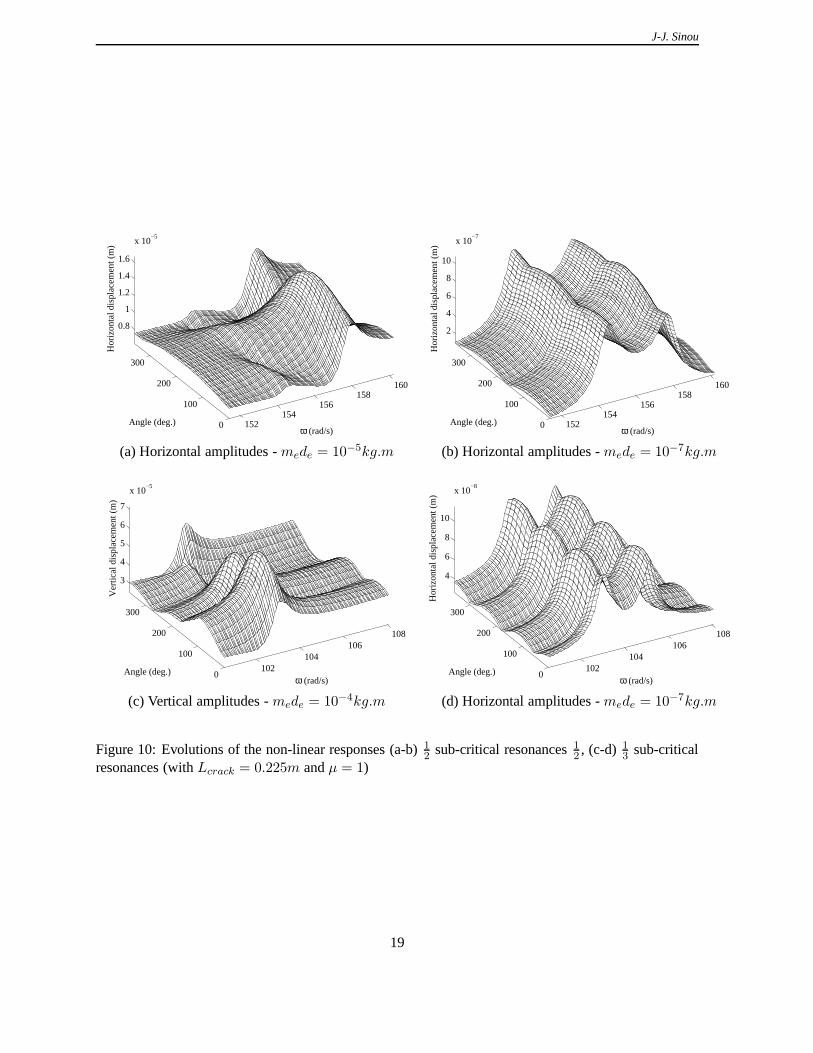
In this section the influence of the crack depth with the interaction of the crack-unbalance orientationis investigated. For the sake of clarity, we focus the study at the 1
3sub-critical resonances. Figures 9
show the third super-harmonic frequency components of the degree-of-freedom situated at the middle ofthe rotor, for various crack-unbalance orientations and three non-dimensional crack depth. These figuresmay be compared with the Figures 6(c) and (d) of the previous section (with a non-dimensional crackdepth that is equal toµ = 1, corresponding to the loss of half the shaft’s area).Due to the crack depth and the crack-unbalance interaction,the magnitudes of the third super-harmonicfrequency components at1
3sub-critical resonances of the first critical speed change:with the decrease of
the non-dimensional crack depth, the influence of the crack is less predominant in the horizontal direc-tion. Moreover, the value of the associated resonance peak decreases with the increase of the crack dueto the reduction of the second moment of area at the location of the crack. For a deep crack (µ = 1 inFigure 6(c)), two resonance peaks appear due to the breathing crack and the associated coupling betweenthe horizontal and vertical direction. When the crack depthdecreases, the first resonance peak disappear(as shown forµ = 0.75 in Figure 9(a)).Then, the crack-unbalance interaction is more predominantin the vertical direction: when the crackdepth decrease, the ratio between the minimum and maximum ofthe third super-harmonic frequencycomponents (as a function of the orientation between the crack and the unbalance) decrease or increase.This reflects the fact that for a deep crack, the crack effect is predominant, whereas the unbalance effectis more important when the crack depth is small.All these results illustrate that the detection of a crack can be difficult due to the interaction of the effectsof the crack and the unbalance. However, the influence of the orientation between the crack and theunbalance appear to be clearly identified if the evolutions of the n× super-harmonic frequency compo-nents at the1
nsub-critical resonances are investigated. It may be observed that the classical non-linear
responses of the cracked rotor at the1
2or 1
3sub-critical resonances may be very complex, as indicated
in Figures 10. Effectively, the evolution of the complete non-linear magnitudes as a function of the rela-tive orientation angle between unbalance and the crack and their interaction drastically affect the systemresponse, making crack detection very difficult. The magnitudes of the1
2or 1
3sub-critical resonances
correspond to the combination of all the harmonic components. So these evolutions of resonance peaksdo not permit a vibration characterization of the cracked rotor system due to the influence and interactionbetween all the super-harmonic frequency components.
5 Conclusion
The evolution of the super-harmonic components of2× and 3× revolution in the sub-critical speedregion can be used as an index to detect a crack in the rotor. However, due to crack-unbalance interactionthe evolutions of the super-harmonic frequency componentsand the associated resonance peaks may bevery complex. It was demonstrated that for a given crack depth, the unbalance does not only affect thevibration amplitude of the1× amplitudes, but also the1
2and 1
3sub-critical resonant peaks. With the
increase of the unbalance magnitude, the1
nsub-critical resonant peaks increase obviously due to the
non-linear behaviour of the breathing crack and the interaction between the crack, gravity and unbalance
14

J-J. Sinou
102104
106108
0
100
200
300
2
4
6
x 10−7
ω (rad/s)Angle (deg.)
Hor
izon
tal a
mpl
itude
(m
)
102104
106108
0
100
200
300
1
2
3
x 10−5
ω (rad/s)Angle (deg.)
Ver
tical
am
plitu
de (
m)
(a) Horizontal amplitudes -mede = 10−4kg.m (b) Vertical amplitudes -mede = 10−4kg.m
102104
106108
0
100
200
300
5
10
15
x 10−8
ω (rad/s)Angle (deg.)
Hor
izon
tal a
mpl
itude
(m
)
102104
106108
0
100
200
300
5
10
15
x 10−6
ω (rad/s)Angle (deg.)
Ver
tical
am
plitu
de (
m)
(c) Horizontal amplitudes -mede = 10−5kg.m (d) Vertical amplitudes -mede = 10−5kg.m
102104
106108
0
100
200
300
2
4
6
8
x 10−8
ω (rad/s)Angle (deg.)
Hor
izon
tal a
mpl
itude
(m
)
102104
106108
0
100
200
300
5
10
15
x 10−6
ω (rad/s)Angle (deg.)
Ver
tical
am
plitu
de (
m)
(e) Horizontal amplitudes -mede = 10−7kg.m (f) Vertical amplitudes -mede = 10−7kg.m
Figure 6: Evolution of the3× super-harmonic frequency components on the1
3sub-critical resonances
(at the middle of the shaft0.25m) with respect to the crack-unbalance orientation (withµ = 1, Lcrack =0.225m and the unbalance located at0.25m)
15

J-J. Sinou
152154
156158
160
0
100
200
300
2
4
6
x 10−5
ω (rad/s)Angle (deg.)
Hor
izon
tal a
mpl
itude
(m
)
152154
156158
160
0
100
200
300
1
2
3
4
5
x 10−4
ω (rad/s)Angle (deg.)
Ver
tical
am
plitu
de (
m)
(a) Horizontal amplitudes -mede = 10−4kg.m (b) Vertical amplitudes -mede = 10−4kg.m
152154
156158
160
0
100
200
300
2
4
6
8
x 10−6
ω (rad/s)Angle (deg.)
Hor
izon
tal a
mpl
itude
(m
)
152154
156158
160
0
100
200
300
5
10
15
x 10−5
ω (rad/s)Angle (deg.)
Ver
tical
am
plitu
de (
m)
(c) Horizontal amplitudes -mede = 10−5kg.m (d) Vertical amplitudes -mede = 10−5kg.m
152154
156158
160
0
100
200
300
2
4
6
8
10x 10
−7
ω (rad/s)Angle (deg.)
Hor
izon
tal a
mpl
itude
(m
)
152154
156158
160
0
100
200
300
2
4
6
8
10
x 10−5
ω (rad/s)Angle (deg.)
Ver
tical
am
plitu
de (
m)
(e) Horizontal amplitudes -mede = 10−7kg.m (f) Vertical amplitudes -mede = 10−7kg.m
Figure 7: Evolution of the2× super-harmonic frequency components on the1
2sub-critical resonances
(at the middle of the shaft0.25m) with respect to the crack-unbalance orientation (withµ = 1, Lcrack =0.225m and the unbalance located at0.25m)
16

J-J. Sinou
305
310
315
320
0
100
200
300
1
2
3
4
5
x 10−5
ω (rad/s)Angle (deg.)
Hor
izon
tal a
mpl
itude
(m
)
900
950
1000
0
100
200
300
0.5
1
1.5
x 10−5
ω (rad/s)Angle (deg.)
Ver
tical
am
plitu
de (
m)
(a)µ = 1, Lcrack = 0.225m, mede = 10−7kg.m (b) µ = 1, Lcrack = 0.125m, mede = 10−5kg.m
Figure 8: Evolution of the amplitudes with respect to the crack-unbalance orientation (a) at the middleof the shaft0.25m for the first harmonic frequency components in the first critical speed with the un-balance located at0.25m, (b) at the one third of the shaft0.15m for the2× super-harmonic frequencycomponents in the1
2sub-critical resonances of the second critical speed with the unbalance located at
0.15m
of the rotor.Even if the crack-unbalance orientation and the unbalance magnitude are unknown, both2× and3×super-harmonic frequency components can be used to detect the presence of crack in rotor. The suitabilityof this approach was verified for various numerical example on a variety of damage location, crack size,unbalance magnitude, and crack size orientation. It appears that the detection of the resonances peaksat the 1
2or 1
3sub-critical resonances and the determination of the associated super-harmonic frequency
components may be useful and acceptable to the industrial community.
References
[1] Wauer, J., 1990. “Dynamics of cracked rotors: Literature survey”.Applied Mechanics Review,43,pp. 13–17 .
[2] Gasch, R., 1993. “A survey of the dynamic behaviour of a simple rotating shaft with a transversecrack”. Journal of Sound and Vibration,160(2), pp. 313–332.
[3] Dimarogonas, A., 1996. “Vibration of cracked structures: a state of the art review”.EngineeringFracture Mechanics,55, p. 831–857.
[4] Sekhar, A., 2004. “Crack identification in a rotor system:a model-based approach”.Journal ofSound and Vibration,270, p. 887–902.
[5] Gounaris, G. D., and Papadopoulos, C. A., 2002. “Crack identification in rotating shafts by coupledresponse measurements”.Engineering Fracture Mechanics,69, p. 339–352.
17

J-J. Sinou
102104
106108
0
100
200
300
2
4
6
x 10−8
ω (rad/s)Angle (deg.)
Hor
izon
tal a
mpl
itude
(m
)
102104
106108
0
100
200
300
2
4
6
8
10
x 10−7
ω (rad/s)Angle (deg.)
Ver
tical
am
plitu
de (
m)
(a) Horizontal amplitudes -µ = 0.75 (b) Vertical amplitudes -µ = 0.75
104106
108110
0
100
200
300
1
2
3
x 10−8
ω (rad/s)Angle (deg.)
Hor
izon
tal a
mpl
itude
(m
)
104106
108110
0
100
200
300
2
4
6
8
10
x 10−8
ω (rad/s)Angle (deg.)
Ver
tical
am
plitu
de (
m)
(c) Horizontal amplitudes -µ = 0.5 (d) Vertical amplitudes -µ = 0.5
104106
108110
0
100
200
300
1
2
3
4
5
x 10−9
ω (rad/s)Angle (deg.)
Hor
izon
tal a
mpl
itude
(m
)
104106
108110
0
100
200
300
2
4
6
x 10−9
ω (rad/s)Angle (deg.)
Ver
tical
am
plitu
de (
m)
(e) Horizontal amplitudes -µ = 0.25 (f) Vertical amplitudes -µ = 0.25
Figure 9: Evolution of the3× super-harmonic frequency components in the1
3sub-critical resonances (at
the middle of the shaft0.25m) with respect to the crack-unbalance orientation and the non-dimensionalcrack depth (withLcrack = 0.225m, mede = 10−5kg.m and the unbalance located at0.25m)
18
J-J. Sinou
152154
156158
160
0
100
200
300
0.8
1
1.2
1.4
1.6
x 10−5
ω (rad/s)Angle (deg.)
Hor
izon
tal d
ispl
acem
ent (
m)
152154
156158
160
0
100
200
300
2
4
6
8
10
x 10−7
ω (rad/s)Angle (deg.)
Hor
izon
tal d
ispl
acem
ent (
m)
(a) Horizontal amplitudes -mede = 10−5kg.m (b) Horizontal amplitudes -mede = 10−7kg.m
102104
106108
0
100
200
300
3
4
5
6
7
x 10−5
ω (rad/s)Angle (deg.)
Ver
tical
dis
plac
emen
t (m
)
102104
106108
0
100
200
300
4
6
8
10
x 10−8
ω (rad/s)Angle (deg.)
Hor
izon
tal d
ispl
acem
ent (
m)
(c) Vertical amplitudes -mede = 10−4kg.m (d) Horizontal amplitudes -mede = 10−7kg.m
Figure 10: Evolutions of the non-linear responses (a-b)1
2sub-critical resonances1
2, (c-d) 1
3sub-critical
resonances (withLcrack = 0.225m andµ = 1)
19
J-J. Sinou
[6] Chen, C., Dai, L., and Fu, Y., 2006. “Nonlinear response and dynamic stability of a cracked rotor”.Communications in Nonlinear Science and Numerical Simulation, In press, p. 15.
[7] Prabhakar, S., Sekhar, A., and Mohanty, A., 2002. “Transient lateral analysis of a slant-crackedrotor passing through its flexural critical speed”.Mechanism and Machine Theory 37 (2002)1007–1020,37, p. 1007–1020 .
[8] Friswell, M., and Penny, J., 2002. “Crack modelling for structural health monitoring”.InternationalJournal of Structural Health Monitoring,1 (2), p. 139–148.
[9] Pugno, N., Surace, C., and Ruotolo, R., 2000. “Evaluation of the non-linear dynamic response toharmonic excitation of a beam with several breathing cracks”. Journal of Sound and Vibration,235(5), p. 749–762.
[10] Sinou, J.-J., and Lees, A. W., 2005. “Influence of cracksin rotating shafts”.Journal of Sound andVibration, 285(4-5), pp. 1015–1037.
[11] Sinou, J.-J., and Lees, A. W., 2007. “A non-linear studyof a cracked rotor”.European Journal ofMechanics A/Solids,26(1), pp. 152–170.
[12] Mayes, I., and Davies, W., 1976. “The vibrational behaviour of a rotatingsystem containinga trans-verse crack”.IMechE Conference on Vibrations in Rotating Machinery,C/168/76, pp. 53–64.
[13] Mayes, I. W., and Davies, W. G. R., 1984. “Analysis of theresponse of a multi-rotor-bearing systemcontaining a transverse crack in a rotor”.Transactions of the ASME Journal of Vibration, Acoustics,Stress, and Reliability in Design,106, pp. 139–145.
[14] P. Pennacchi, N. Bachschmid, A. V., 2006. “A model-based identification method of transversecracks in rotating shafts suitable for industrial machines”. Mechanical Systems and Signal Process-ing, In press, p. 36.
[15] Adewusi, S., and Al-Bedoor, B., 2002. “Experimental study on the vibration of an overhung rotorwith a propagating transverse crack”.Shock and Vibration,9, p. 91–104.
[16] Gasch, R., 1976. “Dynamic behaviour of a simple rotor with a cross-sectional crack”.IMechEConference on Vibrations in Rotating Machinery,C/178/76, p. 123–128.
[17] Zhu, C., Robb, D., and Ewins, D., 2003. “The dynamics of acracked rotor with an active magneticbearing”. Journal of Sound and Vibration,265, p. 469–487.
[18] Henry, T., and Okah, B., 1976. “Vibration in cracked shafts”. IMechE Conference on Vibrations inRotating Machinery,C/162/76, p. 15–19.
[19] Nelson, H., and Nataraj, C., 1986. “The dynamics of a rotor system with a cracked shaft”.Journalof Vibration, Acoustics, Stress, and Reliability in Design,108, p. 189–196.
[20] Lalanne, M., and Ferraris, G., 1990.Rotordynamics Prediction in Engineering, 2 ed. John Wiletand Sons.
[21] Davies, W. G. R., and Mayes, I. W., 1984. “The vibrational behaviour of a multi-shaft, multi-bearing system in the presence of a propagating transverse crack”. Transactions of the ASMEJournal of Vibration, Acoustics, Stress, and Reliability inDesign,106, pp. 146–153.
20

J-J. Sinou
[22] Nayfeh, A., and Balachandran, B., 1995.Applied nonlinear dynamics : analytical, computationaland experimental methods. John Wiley & Sons.
[23] Nayfeh, A., and Mook, D., 1995.Nonlinear oscillations. John Wiley & Sons.
[24] He, J., 2006. “Some asymptotic methods for strongly nonlinear equations”.International Journalof Modern Physics B,20(10), pp. 1141–1199.
[25] Sinou, J.-J., Thouverez, F., and Jezequel, L., 2004.“Methods to reduce non-linear mechanicalsystems for instability computation”.Archives of Computational Methods in Engineering: State ofthe Art Reviews,11(3), pp. 257–344.
[26] Cameron, T. M., and Griffin, J. H., 1989. “An alternatingfrequency time domain method forcalculating the steady state response of nonlinear dynamicsystems”. ASME Journal of AppliedMechanics,56, pp. 149–154.
[27] Flannery, B. P., Teukolsky, S. A., and Vetterling, W., 1992. Numerical Recipes in Fortran, 2 ed.Cambridge University Press.
[28] Cardona, A., Lerusse, A., and Geradin, M., 1998. “Fast fourier nonlinear vibration analysis”.Computational Mechanics,22, pp. 128–142 .
21