destructive load testing of bridge...
TRANSCRIPT

Destructive Load Testing of Bridge No. 1049 – Analyses,Predictions and Testing
Pressley JS, Associate Director – Maunsell WACandy CCE, Technical Director Structures – Maunsell WA
Walton BL, Structural Engineer – Maunsell WASanjayan JG, Associate Professor - Monash University and Consultant to Maunsell
SYNOPSIS
Bridge No 1049 over Baandee Lakes on Great Eastern Highway (Highway 1) is a 5 x 7.5 mspan reinforced concrete flat slab structure built in 1969. The bridge is typical of a number ofsimilar structures in Western Australia, many of which, when analysed by conventionalmethods, appear to be under strength for current vehicle loads.
This paper provides details of two destructive bending, and two destructive punching sheartests carried out on Bridge No 1049. It describes the analyses performed prior to testing,aimed at predicting the response of the structure at both serviceability and ultimate states, anddiscusses the results obtained.
The results showed that in the bending tests, the load-displacement response of the structurewas accurately predicted by LUSAS FE analyses, but a general shear failure mode thataccompanied the ultimate bending failure was not predicted. COBRAS yield line analysesgave accurate predictions of ultimate bending capacity. The results from the punching sheartests indicated that load distribution and pile-soil interaction greatly affect pile-head load atfailure and this must be modelled accurately if analysis is to provide a correct assessment ofpunching shear force.
1 INTRODUCTION
1.1 Western Australian Flat Slab Bridges
The road network in Western Australia contains a significant number of reinforced concrete,flat slab bridges which date back to the early 1960’s. These typically have spans of 6 to7.5 m, the majority with 305 mm thick decks. To date, analysis of these structures has beenbased on the traditional linear elastic approach and the Austroads Bridge Design Code(ABDC). In many cases, this type of analysis has shown these structures to be deficient inload carrying capacity for current heavy loads.
The low load rating of these bridges, many of which are on major arterial routes, produces asignificant constraint on the transport industry, which is exacerbated by the increasing vehicleweights. It is often difficult, disruptive and costly to strengthen these bridges, however, it iswell known, and has been demonstrated in a number of full scale load tests (1 to 4), that flatslab bridges have a load carrying capacity exceeding that indicated by normal linear elasticanalysis methods.
Accordingly, when Bridges No 1048 and 1049 were bypassed as a result of a realignment ofGreat Eastern Highway, Main Roads Western Australia (MRWA) instigated the researchprogramme discussed in this paper. The aim of this research was to develop a more accurateand easily applicable procedure to assess the load carrying capacity of reinforced concrete flatslab bridges. It was considered likely that such a procedure would improve the effective loadrating and thereby reduce the capital expenditure required to strengthen otherwise seeminglydeficient structures.
1.2 Research Programme
The programme for the project comprised three phases:
• Analysis – A variety of analysis methods were used to determine the load at whichfailure would occur. The analyses focussed on two actions which typically govern loadratings of flat slab bridges, bending and punching shear;
• Testing – Four full scale destructive load tests on the structure to determine the failureloads; and
• Outcomes – Based on the results of the load tests, determination of appropriatemethodologies to load rate flat slab bridges similar to Bridge No. 1049.
These phases are discussed in this paper, with phase three further expanded for shear effectsin a companion paper in these Proceedings, titled “Shear Damage Control in Assessing FlatSlab Bridge Decks”.
1.3 Serviceability and Durability
MRWA requested that the tests also provide information on the serviceability of flat slabbridges under the effects of a number of heavy load passages. To quantify this, flexuralcracks widths during load cycling at service load levels were measured during the testing. Itwas considered that this would:
• Establish if excessive residual crack widths would become a limiting durability factor inload rating; and
• Identify any tendency for reinforcement yield strength to be exceeded in local areas ofslab, resulting in cumulative increases in crack widths.
2 BRIDGE DESCRIPTION
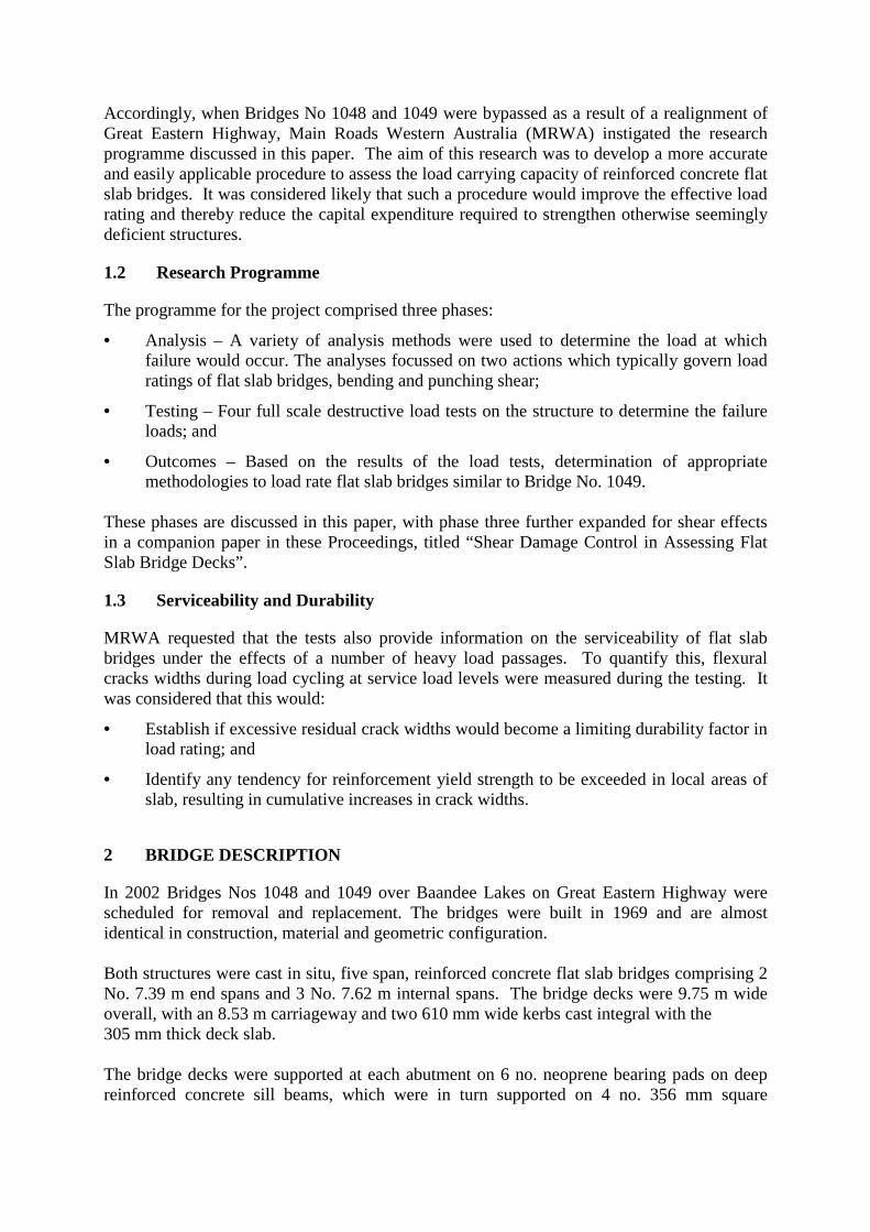
In 2002 Bridges Nos 1048 and 1049 over Baandee Lakes on Great Eastern Highway werescheduled for removal and replacement. The bridges were built in 1969 and are almostidentical in construction, material and geometric configuration.
Both structures were cast in situ, five span, reinforced concrete flat slab bridges comprising 2No. 7.39 m end spans and 3 No. 7.62 m internal spans. The bridge decks were 9.75 m wideoverall, with an 8.53 m carriageway and two 610 mm wide kerbs cast integral with the305 mm thick deck slab.
The bridge decks were supported at each abutment on 6 no. neoprene bearing pads on deepreinforced concrete sill beams, which were in turn supported on 4 no. 356 mm square

prestressed concrete driven piles. The piers had 4 no. 356 mm square piles, recessed 25 mminto the deck soffit as supports. Refer Fig 1 for general views of the bridge.
Figure 1: General Views of Bridge No.1049
3 STRUCTURAL ANALYSES
3.1 Introduction
The original plan was to carry out two sag bending tests and one punching shear test. It wasdecided at an early stage of the project that two vehicle configurations should be tested, asingle T44 tandem axle group (1.8 m wide, 1.2 m long) and dual T44 tandem axle groupsoccupying adjacent design lanes.
A second punching shear test was added as it was felt that two replicate tests would improvethe reliability of the results. A modified load configuration, 1.8 m long x 1.8 m wide, wasrequired for the punching shear tests to avoid the expected shear failure cone and to ensurethat a symmetrical failure occurred about the pile, allowing direct comparison to existingreported experimental work.
3.2 Materials
During demolition of Bridge No. 1048 in 2002, concrete and reinforcement were removed andsent for testing. The results of this testing are considered typical for both bridges.
7 no. 95 mm concrete cores were tested for both compressive strength and Young’s modulus,and 9 specimens of reinforcement were tested to determine yield stress, ultimate tensile stressand Young’s modulus. The mean values of these test results were used as “best estimates” ofmaterial properties for Bridge No. 1049 to predict failure loads.
3.3 Bending
Detailed linear elastic and plastic analyses of Bridge No 1049 were carried out, aimed atdetermining the critical load configurations and magnitudes required to cause failure.
3.3.1 Linear Elastic Analyses
Elastic analysis is widely used for both bridge design and load rating. Although the methodsare strictly only relevant in the elastic range of a structure, they are generally extrapolated to

the ultimate limit state because they are simple to derive and apply, and because theygenerally provide a conservative prediction of ultimate load effects. Elastic analysis does nottake into account the inherent ability of reinforced concrete flat slabs to redistribute loadeffects width-wise, as well as length-wise, by inelastic actions. Cracking of the concrete willaffect load distribution even at low load levels, whilst yielding of the reinforcement can causesignificant load redistribution prior to failure.
The elastic analysis techniques used during this research included:
• Grillage analysis; and
• Plate bending FE analysis.
3.3.2 Plastic and Non-Linear Analyses
Plastic and non-linear analyses of Bridge No. 1049 were also carried out to predict the loadrequired to cause failure and the likely failure mode.
Three types of analysis were used:
• One dimensional (1D) line beam with various plastic hinge mechanisms;
• Two dimensional (2D) yield line (using proprietary COBRAS software); and
• Three dimensional (3D) non–linear finite element (FE, using LUSAS software).
Initially, a simple line beam plastic analysis was carried out for dual T44’s, modelling thedeck as a beam. The failure mechanisms examined were plastic hinges in various locations inboth the hog and sag zones, across the full width of the deck. Adopting an energy approach,the load position and magnitude, and the hinge positions required to cause failure at thelowest energy state were identified.
Following this, comprehensive yield line analyses of the slab were carried out for the singleT44 and dual T44 tandem axle configurations, using the COBRAS (5) software package.Best estimates of the geometry and material properties were entered into the program andvarious iterations in load position and failure geometry were carried out to identify the loadpatterns which caused failure at the lowest energy state.
Finally a 3D non-linear FE model of a single span of the bridge was developed in LUSAS (6).The model comprised 8-noded, 3D concrete brick elements with bar elements for everyreinforcing bar in the span. Both of these materials had non-linear properties assigned. Therewere 6 layers of brick elements, including one layer top and bottom representing coverconcrete. The deflected shape of this model for single T44 loading is presented in Fig 2below.
Figure 2: Discretised End Span Model – Deflected Shape

There were several aims of the LUSAS analysis, including:
• Predicting the structural response to loading (load-displacement plot);
• Providing an alternative assessment of the collapse load;
• Identifying alternative failure modes not identified by COBRAS; and
• Confirming or disputing the COBRAS results.
The same T44 load patterns and positions as in the COBRAS analysis were adopted. The loadmagnitudes were incrementally increased and deflections at critical points plotted against loadincrements, to develop load-displacement plots, as shown in Fig 9 in Section 5.2.
3.4 Punching Shear
To assess the punching shear capacity at a square-section pile-head, a portion of the slabaround the pile was modelled. To minimise the size of the stiffness matrix, only a quarter ofthe pile was modelled, and to simplify the boundary conditions the model was extended to theadjacent column and for the full length of the span, refer Fig 3. A graphical representation ofthe model is shown in Fig 3.
Figure 3: Punching Shear Model Area, Discretisation and Boundary Conditions
4 LOAD TESTS
4.1 Test Programme
From the results of the structural analyses, the predicted failure loads were determined for thechosen loading patterns, from which a Test Plan was developed. To apply the actual loads,ground anchors were installed through holes cored in the deck at each T44 wheel positionwith hydraulic jacks positioned to apply the load.
Three different load configurations were identified to give the most useful data:
• Modified Single T44 Tandem Axle Group for two punching shear tests, 1.8 x 1.8 mspacing;
• Standard Single T44 Tandem Axle Group for sag bending test No. 1; and
• Standard Dual T44 Tandem Axle Groups for sag bending test No. 2.
Model area
Pier 1 Pier 2 Pier 3 Pier 4Abut 1 Abut 2
T44 tandemaxle load

It was decided that the bending tests would be carried out in two stages:
• Stage 1 - load cycling at elastic load levels, followed by
• Stage 2 - loading to ultimate failure.
Crack widths were measured during Stage 1 to identify the effects of allowing the passage ofheavier loads on the serviceability and durability of the structure.
During all tests, displacement information was recorded using two techniques, total stationsurvey and photogrammetry. The survey information allowed real-time displacementinformation to be compared to the predicted load-displacement behaviour from the LUSASanalyses to provide an indication of how the tests compared to the predicted responses.
The photogrammetry required a grid pattern of targets to be installed on the loaded spanduring each of the sag bending load tests, with two digital cameras set up on tripods takingimages at each load increment. This information, once post-processed, provided the deflectedshapes of the structure which gave important information for the assessment of transversedistribution effects, and particularly in the understanding of general shear behaviour atultimate loads. Both techniques adopted provided an accuracy of ± 1 mm, which was morethan adequate for the purposes of these tests.
The main advantage of using photogrammetry was the speed at which the data from manylocations could be recorded, as it took only seconds for the images to be captured. The speedof data acquisition also removed any concerns that the measurements may have been affectedby creep of the structure under sustained loads. Total station survey was used on a fewselected photogrammetry targets for correlation and deflection check purposes at all loadincrements.
For the punching shear tests targets were installed over each pile at the pier being loaded aswell as the adjacent piers. The information obtained from these results gave an indication ofthe load distribution both between piers and amongst the piles at a pier.
4.2 Load Test Activities
4.2.1 Punching Shear
The punching shear tests near the centre of the bridge were carried out first as they requiredthe minimum amount of survey set up and there was no load cycling.
The proposed loading procedure was for the jacks to sit on chamfered steel plates representingthe wheel footprints of a T44, the plates sitting on rubber bearing pads to take the unevennessout of the asphalt. This was believed to be as realistic as could be achieved. The setup isshown in Fig 4 below.

Figure 4: Punching Shear Jack SetupDuring the first test, loading was carried out in increments of 20 t up to a total applied load ofapproximately 135 t and then smaller increments were adopted as the predicted failure load of196 t was approached. At a total applied load of 192 t large rotations of the jacks occurreddue to local softening of the asphalt (the shade temperature exceeded 40oC). Loadingcontinued up to a total applied load of 325 t, after which it was decided to unload, remove theasphalt and rubber bearings and repeat the test.
In the retest, large load increments were adopted to a total applied load of 360 t. Failureoccurred during the next increment at a total applied load of 369 t, with a sudden, brittlefracture of the slab, and two distinct loud bangs. There was a clearly visible failed areaaround the loaded pile with a step in the top surface of some 50 mm. Detailed inspectionconfirmed that the slab had failed with a classic punching shear “mushroom head”, botharound the loaded pile and at an adjacent pile, the latter explaining the second loud bang.
The second punching shear test was carried out adopting the lessons learnt during the first,with the load plates bearing directly onto the structural concrete. As in the previous test,larger load increments were initially used, however at a total applied load of 240 t, or 60 t perjack, one of the ground anchors yielded in pull out. As the tendon retained a load ofapproximately 57 t it was decided to continue loading on the remaining three anchors, whilstattempting to maintain the load on the yielded anchor.
Loading continued up to a total applied load of 352 t, 100 t on the three sound anchors and52 t on the yielded anchor. This was the maximum safe working load of the jack manifoldand the decision was therefore made to terminate the test. Sudden failure of the slab did notoccur, however inspection found cracking in the soffit close to the pile-head, similar to thataround the two piles where punching shear failure had occurred in the previous test. Thisindicated that the punching shear capacity of the slab had been approached, but not exceeded.
4.2.2 Bending
The two bending tests each had two stages, load cycling and subsequent loading to failure.Again, the bearing plates were placed directly onto the structural concrete. The jack andphotogrammetry setup is shown in Fig 5 below.

Figure 5: Single T44 Test Setup and Ultimate Flexural Cracks on the Soffit
The first test had a single T44 tandem axle group load configuration, 1.2 m longitudinal axlespacing and 1.8 m transverse wheel spacing, in one of the end spans. During the load cycling,maximum crack widths under service loads were documented as well as the residual crackwidths when the structure was unloaded. Cracks closed to approximately 0.2 mm after thestructure had been subjected to a total applied load of 160 t.
Total station survey readings were taken whilst loading and unloading to confirm that thestructure had not sustained any permanent deflections during load cycling. After load cycling,the structure was loaded from 160 t total load to 240 t in 20 t increments, after which smallerincrements were adopted to approach the expected failure load of 252 t (63 t per jack). Realtime plotting of load-displacement curves during the test indicated an excellent fit between thepredicted and actual behaviour of the structure, refer Fig 9 in Section 5.2.
Large deflections to 80 mm were noted around the loaded region as the predicted failure loadwas approached. At a total applied load of 249 t (62 t per jack), initial yielding occurred witha slow cracking sound from localised compressive failure of the kerb concrete. Largetransverse flexural cracking in the sagging region was also evident on the soffit (see Fig 5above). Fig 6 below shows a plot of these flexural cracks, as observed just before failure,together with the shear crack location on the soffit after failure. The flexural cracks wereorthogonally orientated, with no evidence of diagonal cracking in plan, as was expected fromyield line assumptions. Vertical cracking in the kerb was observed in the hogging region overthe pier. After initial yield, the jacks held a total load of 223 t.
Once the structure had reached equilibrium and sounds of cracking stopped, the structure wascarefully loaded back to 249 t. As the load was increased a sudden shear failure occurred at atotal load of 254 t (63 t per jack). An L-shaped shear failure surface around the loaded regionwas observed, similar to a large scale punching shear failure of the entire loaded regiondownwards. A shallow angled, 50mm wide, diagonal crack extended from the soffit, throughthe thickness of the concrete, breaking out at the top surface near the loaded area. Fig 6 belowcontains plots of the L-shaped shear crack which was evident in both single and dual T44tests.

Figure 6: Single and Dual T44 Tests – Plots of Soffit CrackingThe second bending test in the other end span had a dual T44 load configuration, two tandemaxle groups occupying two adjacent design lanes. 8 jacks were required. Two of the jackscould not release load and load cycling was therefore carried out using six jacks only.Loading to failure was carried out using all 8 jacks. The test setup is shown in Figure 7 below.
Figure 7: Dual T44 Test – Setup and Soffit Shear Cracking after FailureElastic cycling was carried out and crack measurements taken up to a total applied load of180 t (30 t per jack). Crack widths of up to 0.45 mm were documented at the highest load,closing to approximately 0.2 mm after unloading. The cracks that were readily visible at thisserviceability load level are shown in Fig 6 above.
After the last elastic cycle, all eight jacks were loaded to 22.5 t per jack to produce the sametotal load as on six jacks. Measurements were retaken to confirm that there was no differencebetween six jacks and eight jacks loaded.
Loading progressed with the eight jacks from a total applied load of 180 t to 320 t (40 t perjack) in approximately 40 t load increments, with smaller increments used to approach theexpected failure load of 352 t. Loading then continued until failure occurred at 398 t.

A maximum deflection of 120 mm was recorded just prior to failure which was characterisedby a sudden shear fracture around the loaded region, again similar to a large scale punchingshear failure of the loaded zone, downwards.
As before a large L-shaped shear crack was evident around the loaded area, producing adistinct step in the deck of approximately 70 mm, approximately halfway between T44 andpier. A return visit was made to the bridge a few weeks later and a section of the concretesaw-cut out to identify the through-thickness crack geometry. The location is shown by thehatched rectangle in Figure 6 and the photo is shown in Fig 8 below.
Figure 8: Dual T44 Test – Through - Thickness Shear Failure SurfaceThe failure surface comprised a shallow angled, diagonal crack extending from the soffit,some distance away from the loaded area, through the thickness of concrete, breaking out at45o to the top surface, near the loaded area.
Unlike the first bending test, there was no distinct compressive failure of the kerb concrete,however the kerb upstand separated from the slab with a large longitudinal crack at theinterface. The load-deflection plot is shown in Fig 9.
5 DISCUSSION OF LOAD TEST RESULTS
5.1 Punching Shear
There was a significant difference between the ABDC predicted capacity (1,202 kN) and themean estimated failure load for the pile-head (1,630 kN). Detailed analysis was carried out toestablish the proportion of the maximum applied loads of 3,457 kN and 3,541 kN that wasdistributed into the pile-head in question. Pile settlement and a flexurally cracked concreteslab were considered to have a major influence and the rationale is discussed with other shear-related issues in a companion paper titled “Shear Damage Control in Assessing Flat SlabBridge Decks”.
5.2 Bending
The predicted ultimate loads were calculated using the standard linear elastic Austroadsapproach, yield line and non-linear FE analyses. The actual applied loads at which failureoccurred compared well with the loads predicted by both COBRAS yield line and LUSAS FEanalyses. Table 1 below shows this.

Predicted Failure Load (kN) % of Predicted Failure LoadAnalysisTechnique Single T44 Dual T44 Single T44 Dual T44Austroads* 1,018 1,460 42 % 37 %Yield Line 2,340 3,160 96 % 81 %
FE 2,480 3,460 101 % 89 %Actual Test
Result 2,445 3,901 - -
Table 1: Comparison of Predicted and Actual Bending Failure Loads* - The maximum applied load to cause failure of a grillage member from an elastic grillage
analysis with capacities based on Austroads methodology.
The load vs midspan displacements measured in the tests were compared to the responsespredicted by LUSAS and Fig 9 below shows very good correlation.
Figure 9: Load – Displacement Plots, Single T44 Test (left) and Dual T44 (right)
The tests did not confirm the classic assumed diagonal yield line patterns (in plan), and theflexural soffit cracks observed support a different mechanism, characterised more by dishingwith very many transverse “yield lines” and one main longitudinal flexural crack.
5.3 Serviceability
The residual crack widths were less than 0.2 mm for total applied loads of 160 t and 180 t forthe single T44 and dual T44 loads, respectively. This is the limit below which reinforcedconcrete is generally considered to be durable. After load cycling, no significant permanentdisplacements were recorded, indicating reinforcement stresses within their elastic range.
6 APPLICATION OF RESULTS
6.1 Bending
Both the yield line and 3D non-linear FE analyses accurately modelled the failure loads of thestructure. Of the two, the COBRAS yield line software is significantly easier to use and is
Single T44 Bending Test
48.9
0
50
100
150
200
250
300
0 20 40 60 80 100Displacement (mm)
Tota
l Loa
d (t)
0
3
5
8
10
13
15
Actual TestPredicted
100% T44 Rating - Strength Factored LL
Reinforcement yielding locallyFlexural
cracks 0.4,
closed to 0.1mm
Dual T44 Bending Test
88.1
0
100
200
300
400
0 20 40 60 80 100 120 140
Displacement (mm)
Tota
l Loa
d (t)
0
2
4
6
8
10
Actual Test
Predicted
100% T44 Rating - Strength Factored LL
Reinforcement yielding locallyFlexural
cracks 0.3,
closed to 0.15mm

considered to be an appropriate analytical tool for assessing the bending capacity of slat slabbridges, despite the lack of correlation of flexural crack patterns between theory and practice.Supporting this conclusion is a companion paper titled “Reliability Analysis of BaandeeLakes Bridge, WA” which summarises a rigorous reliability and sensitivity analysis on theuse of yield line analysis. The findings concluded that if characteristic values for both materialstrengths and geometry were used, then the resulting Reliability Index would be greater thanthe 3.4 suggested by Eurocode EN 1990 (2002), and would be acceptable.
It must be stressed that the above evaluation is applicable only for bending of deck structuresof similar type and construction to Bridge No. 1049. Yield line analysis does not incorporateshear assessment and this is discussed in a companion paper in these Proceedings, titled“Shear Damage Control in Assessing Flat Slab Bridge Decks”.
7 CONCLUSIONS
From the four tests carried out the following conclusions have been reached:
• Both yield line and 3D non-linear FE computer analyses produce accurate ultimateloads for bending within a single span but do not predict general shear failure.
• Concrete flat slab bridges of similar type to that tested have load carrying capacities inbending and punching shear significantly greater than would be obtained by linearelastic analysis, and the application of the current ABDC.
• Further investigation is required into the general shear failure phenomenon thataccompanied bending failure in these tests, as this may significantly limit load ratings inmany cases.
ACKNOWLEDGEMENT
The authors acknowledge Main Roads WA for their initiative in proposing and funding theresearch programme, and their permission to use material in this paper.
REFERENCES
1 GIUFRE, A., HARITOS, N., MENDIS, P., HIRA, A., and HEYWOOD, R., “Full Scale LoadTesting of Barr Creek Bridge”. Proceeding AUSTROADS 4th Bridge Conference, Sobol, GWDand Chaplin G (editors), AUSTROADS, Volume 1, 2000, December, pp191-204.
2 HARITOS, N., HIRA, A., MENDIS, P. “Theoretical Analysis of Barr Creek Bridge”.Proceeding International Conference on Mechanics of Structures, Materials and Systems, HadiMNS and Schmidt LC (editors), UNIVERSITY of WOOLONGONG, 1999, pp 67-74.
3 MILLAR, R.A., AKTAN, A. E., and SHAROOZ, B. M., “Destructive Testing ofDecommissioned Concrete Slab Bridge”. Journal of Structural Engineering, ASCE, Vol. 120,No. 7, July, 1994, p 422 – 440.
4 MIDDLETON, C.R., “Case Studies from the UK Using Yield Line Analysis for ConcreteBridge Assessment”. Proceeding AUSTROADS 3rd Bridge Conference, AUSTROADS,Chrigwin, G., J. (Editor), Volume 1, December 1997, pp 84 – 98.
5 COncrete BRidge ASsessment (COBRAS), Version 1.7, Release 14, Middleton, C.R., UnitedKingdom.
6 LUSAS, Version 13.5, FEA Ltd, Surrey, United Kingdom.