design, thermal and computational fluid dynamic … · a loop heat pipe (lhp) is a two-phase heat...
TRANSCRIPT

TFAWS 2019 – August 26-30, 2019 1
DESIGN, THERMAL AND COMPUTATIONAL FLUID DYNAMIC ANALYSES ON LOOP HEAT PIPE WICK AND MAUFACTURING WITH SELECTIVE LASER MELTING
Togaru Lavanith, Naganathan Karthik Mechanical Engineering Department, Kakatiya Institute of Technology & Science,
Warangal - 506015, Telangana, India.
ABSTRACT
A loop heat pipe (LHP) is a two-phase heat transfer device that uses capillary action to remove heat from a source and passively move it to a condenser or radiator. LHPs are similar to heat pipes but have the advantage of being able to provide reliable operation over long distance and the ability to operate against gravity. They can transport a large heat load over a long distance with a small temperature difference. This paper summarizes the new design, computational fluid dynamics (CFD) and thermal analyses of loop heat pipe (LHP) wicks (primary and secondary wicks). The project was motivated to evaluate the best performance conditions of LHP for an increase in effectiveness with reduction of cost in production by employing selective laser melting (SLM) an additive manufacturing technology. The work was completed in a multi-step process. Key aspect for achieving the optimum performance of loop heat pipe is to ensure that the wick structure and its appropriate assemblage perform within their original thermal-physical design specifications for this first LHP wicks was designed to control the porosity and to increase its permeability, which is not possible in traditional manufacturing practice (sintering). To enhance the working efficiency and to increase LHP effectiveness by using different working fluids, wick material, shape of different parts of LHP are analyzed using CFD and thermal analyses tools. From CFD results, the design was optimized and parts of LHP were redesigned accordingly, this design is made compatible with the additive manufacturing (AM) technique SLM for fabrication of LHP wick(s) which is advantageous to control its geometric size of the internal wick passages, aiming to achieve an optimal design according to the specified requirements. It highlights the relevance of this optimization procedure in the performance from the start-up behavior under different working conditions: input power, ambient temperature and mass charge.

TFAWS 2019 – August 26-30, 2019 2
NOMENCLATURE, ACRONYMS, ABBREVIATIONS
A wick cross sectional area, m2 Greek Symbols
Cp specific heat capacity of liquid, KJ/kg.K ρ Density, kg/m3
h enthalpy, KJ/kg μ Dynamic viscosity, kg/s.m
hcc convection coefficient of compensation chamber, W/m2K β
Volumetric ratio (0 to 1), 𝑉𝑣,𝑐𝑐
𝑉𝑐𝑐
k thermal conductivity, W/m.K σ Surface Tension, N/m
l pipe length, m ε Porosity (0 to 1)
L wick length, m Subscripts
LHP Loop Heat Pipe w wick
M mass, kg v vapour
ṁ mass flow rate, kg/s sat saturated condition
P pressure, Pa s solid
Q heat flow, W eff effective
R pipe Radius, m l liquid
T temperature, K c condenser
V volume, m3 cc compensation chamber
X quality cc,sat compensation chamber saturation condition
TFAWS 2019 – August 26-30, 2019 3
1. INTRODUCTION
Loop heat pipes (LHPs) are highly efficient two-phase heat transfer devices that utilize the evaporation and condensation of a working fluid to transfer heat, and capillary forces developed in fine porous wick to circulate the working fluid1. Compared with traditional heat pipes, LHPs have the advantage of transporting a larger amount of heat over a longer distance with quite strong antigravity capability. Moreover, the arrangement of LHPs to connect the heat source with heat sink becomes more convenient due to the employment of flexible transport lines.
Two loop heat pipes were built and tested, where they differ from each other on their compensation chamber geometry and high-grade acetone was used as working fluid, in substitution of the so-used ammonia2. Acetone has presented to be a good choice as working fluid during the life tests over the time, which has been important for the accomplishment of the project goals. Life tests were conducted which have resulted in generation of important data that has been applied on the design and construction of loop heat pipes toward their use in future space applications. Performing life tests with both LHPs using acetone as working fluid has shown the potential of using this substance for space applications in two-phase thermal control devices due to its characteristics related to low working pressure and hazard conditions. Both LHPs have shown good capability in managing the heat load profiles without any tendency of temperature overshooting or evaporator failure.
An experimental investigation was presented by fabricating a series of capillary wicks for loop heat pipes (LHPs), using two different methods, the cold-pressing sintering and direct loose sintering, and effect of different methods, compositions and sintering parameters on their properties in terms of porosity, permeability and pore radius3. The Archimedes method and Scanning Electron Microscope (SEM) measured porosity and pore radius, respectively. Permeability of the wicks was compared by calculation using empirical equation. The capillary wicks were successfully fabricated by using two different methods; the optimal capillary wick was found to be sintered at 650℃ for 30 min, using direct loose sintering technique, with 90% nickel and 10% copper. The results have shown that Compared to the loose sintered wicks; cold-pressed sintered wicks have lower porosity and permeability, but higher pore radius. The parameters could be well predicted during cold pressing sintering process. Copper, as the additive in the Ni-Cu sintered wick, could affect the porosity and permeability on both sides.
A description of the fine pore sintered powder metal wick structure fabrication technology to the United States for use in the construction of U.S. made LHPs, capillary pumped loops (CPLs) and heat pipes was made4. Sintered powder metal wick structures have been used in U.S. made heat pipes for over twenty-five years. The typical pore radii for these wick structures range from 10 to 100 microns. Use of a wick material with a pore radius less than 10 microns was limited due to the high-pressure drop encountered when used in a standard heat pipe. Conversely, the Russian loop heat pipe is able to get around this high-pressure drop constraint due to its unique evaporator design. Prior to the work presented, the U.S. concentrated on the development of wick structure materials above 10 microns, which created a technology void

TFAWS 2019 – August 26-30, 2019 4
with the advent of the LHP. Russian fine pore wick structure fabrication technology has been successfully transferred to a U.S. company. The properties of the U.S. made wick material are essentially the same as the Russian material and in some instances are felt to be stronger and more machinable. Work in the future focused to extend this fine pore fabrication technology to include titanium and stainless steel materials.
An investigation on the classification of LHP operating modes based on the criterion of presence or absence of the working fluid vapor phase in the compensation chamber (CC) was presented. It gives a description of method of calculating the LHP operating temperature for every operating mode and shows the characteristic features, advantages and disadvantages of every mode. One of the main factors that influence the operating temperature of a loop heat pipe (LHP) is the distribution of a working fluid in the device5. Because of experimental and analytical investigations, the two main operating modes of LHP are:
1. An LHP operates in the presence of the working-fluid vapor phase in the compensation chamber.
2. An LHP operates in the absence of the working-fluid vapor phase in the compensation chamber.
The LHP operating temperature depends on the operating mode of the heat-transfer device. He showed that at the same heat load and identical external conditions an LHP has a higher operating temperature when it functions with a partially filled compensation chamber. The reason of temperature hysteresis in the region of low heat loads is different LHP operating modes, and in the region of high heat loads – capillary hysteresis. Extensive experimental and FEM simulation investigations on the LHP investigated that heat transfer characteristics of using nanofluids in an LHP as a working medium for heat input range from 20 W to 100 W6. LHP performance using silica (SiO2–H2O) nanofluid with particle volume fraction of 3%, which was used as a coolant revealed an average decrease of 28%–44% at heat input ranging from 20 W to 100 W in total thermal resistance of LHP when compared with pure water. The LHP that is made of transparent plastic tube was used to visualize the flow patterns. As power increases, three different flow patterns were observed in the vapor line. They are bubbly, slug and annular. The LHP using SiO2–H2O nanofluid yields lower temperature and reaches its steady state faster than LHP using pure water. As the use of nanofluid in heat pipe is gaining attraction in an impetuous development of technology in this sphere and accompanied by a constantly growing amount of heat dissipated by functional components, for instance such as desktop PC CPUs, the present study would definitely open ways for further research.

TFAWS 2019 – August 26-30, 2019 5
2. LHP THEORY
When compared to the electrically pumped loops, LHPs provide passive thermal control system without any power demands, lower cost, longer system life, higher runtime reliability and thus sustainable cooling technology for the energy extensive electronic devices (cost/technology dominance). At present, LHPs are gaining significant research attention for performance improvement and cost reduction to implement them successfully in the commercial areas of interest. Manufacturing of heat pipe involves relatively simple processes on metal tube that include cutting, swaging, sinter attachment of powder to tube internal wall, charging working fluid and welding. In loop heat pipe, the evaporator (including evaporator internally grooved portion, compensation chamber and wick), condenser (including flow tubes, fins and connectors) and heat transfer tubes (vapour and liquid lines) are each separately manufactured and then assembled through brazing/welding process. This adds to both cost as well as manufacturing complexity of LHP. Unlike conventional heat pipe, in which evaporator structure, that comprises of wick layer sintered attached to the tube internal surface, has simpler design and structurally identical to the other sections of pipe, the LHP evaporator has much more complicated geometry and structurally altogether different from the rest of the loop.
Evaporator is the most complex and costly component of the LHP assembly. Fabrication of evaporator includes machining internal flow channels in the tube (for cylindrical evaporator) or plate (for flat evaporator), sintering of wick structure, integration of wick inside the evaporator, sealing of evaporator container by welding/brazing and attachment of flow tubes (vapour/liquid lines). Any fabrication simplicity or technology development with respect to the abovementioned processes can provide the consequential cost reduction and promotion of the passive loop devices in high flux thermal management applications.
Operational characteristics of the loop heat pipe including startup time, steady state temperature profile within range of applied heat load and component/overall thermal resistance are principally dictated by the loop evaporator design and configuration. In essence, majority of the LHP performance issues are associated with the loop evaporator design considerations and construction.
Wick is the most critical component of the LHP that dictates its runtime reliability and thermal performance. Sintering of the wick structure with the required physical properties needs rigorous evaluation and is one of the most challenging tasks in the fabrication of the LHP. In addition, the present investigation discusses methods for assembling the capillary evaporator and qualification tests that can guarantee the integrity of the evaporator and overall loop system.

TFAWS 2019 – August 26-30, 2019 6
3. OPERATING PRINCIPLE OF LHP
Figure 1. Schematic of an LHP.
The above figure shows the flow schematic diagram of an LHP. It consists of an evaporator, a condenser, a compensation chamber, and vapor and liquid transport lines. Only the evaporator and the compensation contain wicks; the rest of the loop is made of smooth wall tubing. The wick in the evaporator is made with fine pores for purpose of developing a capillary pressure to circulate fluid around the loop, while the wick in the compensation chamber is made with larger pores for purpose of managing fluid ingress and egress. The operating principle of the LHP is as follows. As heat is applied to the evaporator, liquid is vaporized and the menisci formed at the liquid/vapor interface in the evaporator wick develop capillary forces to push the vapor through the vapor line to the condenser. Vapor condenses in the condenser and the capillary forces continue to push liquid back to the evaporator. The waste heat from the heat source provides the driving force for the circulation of the working fluid and no external pumping power is required. The two-phase compensation chamber stores excess liquid and controls the operating temperature of the loop. In order for the loop to continue to function, the wick in the evaporator must develop a capillary pressure to overcome the total pressure drop in the loop. One of the advantages of a capillary loop is that the meniscus in the evaporator wick will automatically adjust its radius of curvature such that the resulting capillary pressure is equal to the total system pressure drop.

TFAWS 2019 – August 26-30, 2019 7
Figure 2: Parameters for capillarity
The total pressure drop in the system is the sum of frictional pressure drops in the evaporator grooves, the vapor line, the condenser, the liquid line, and the evaporator wick, plus any static pressure drop due to gravity:
∆Ptot = ∆Pgroove + ∆Pvap + ∆Pcon + ∆Pliq + ∆Pw + ∆Pg* (1)
The capillary pressure rise that the wick can develop is given by
∆Pcap = 2σcosθ /R (2)
Where σ is the surface tension of the working fluid, R is the radius of curvature of the meniscus in the wick, and θ is the contact angle between the liquid and the wick. As the heat load to the evaporator increases, so will the mass flow rate and the total pressure drop in the system. In response, the radius of curvature of the meniscus decreases to provide a higher capillary pressure that matches the total system pressure drop. The radius of curvature will continue to decrease with increasing heat loads until it is equal to the pore radius of the wick, Rp. Under this condition, the wick has reached its maximum capillary pumping capability:
∆Pcap, max = 2σcosθ /Rp (3)
Further increase of the heat load will lead to vapor penetration through the wick and system de-prime. Thus, under normal operation, the following condition must be satisfied at all times:
∆P < ∆Pcap (4)

TFAWS 2019 – August 26-30, 2019 8
The compensation chamber is located close to the evaporator. In fact, the compensation chamber is usually made as an integral part of the evaporator, and a secondary wick is used to connect the two elements. Liquid returning from the condenser always flows through the compensation chamber before it reaches the evaporator. The secondary wick provides a liquid link between the compensation chamber and the evaporator so that the evaporator will always be replenished with liquid. There are two major advantages of such a design. First, the loop can be started by directly applying power to the evaporator without the need of preconditioning. Second, the evaporator is tolerant of vapor bubbles in its liquid core. Because the primary wick is made of metal powder with a high thermal conductivity, liquid evaporation usually takes place inside the evaporator core and vapor bubbles are present there in most operation. To prevent vapor bubbles from accumulating inside the evaporator core, the secondary wick design incorporates vapor arteries, which allow vapor bubbles to vent to the compensation chamber. Regardless whether or not vapor bubbles are present, the evaporator core can be 3considered as an extension of the compensation chamber and both have the same absolute pressure during steady operation.
*( for on earth applications)
4. START-UP OF LHP
Loop startup is a condition where the LHP cycle should start before it can commence its service, during which the compensation chamber temperature will change from its initial value to a final steady state value. The change of the compensation chamber temperature during the startup transient can be smooth, i.e. the temperature of compensation chamber changes gradually. However, in many cases an overshoot or undershoot of the reservoir temperature can occur.
Figure 3. Temperature Overshoot during Startup

TFAWS 2019 – August 26-30, 2019 9
4.1 Startup scenarios
Depending on the thermodynamic states of the fluid in the evaporator core and the fluid in vapor grooves, four possible situations prior to loop startup are found. It is assumed that, in all situations, the entire loop is initially at the ambient temperature (condenser is an exemption as it is coldest of all other parts.)
In 1st situation, the vapor grooves on primary wick contain vapor and the evaporator core/ secondary wick region is completely filled with liquid. This leads to the exemplary case where the loop starts in a flash as heat load is applied to the evaporator. After the cold liquid from the condenser reaches the compensation chamber, the compensation chamber temperature will decrease and the loop will eventually reach a steady state.
In 2nd situation, both the evaporator core and vapor grooves contains vapor. The loop will also start as soon as the heat load is applied to the evaporator. The transient period and the extent of the temperature overshoot depend on the heat load and the initial temperature of the liquid line and the heat exchange between the liquid line and its surroundings. A low heat load will have a long transient period and a large temperature overshoot because of the parasitic heat gain from the environment along the liquid line. The parasitic heat gains decreases as the evaporator heat load increases.
Figure 4. LHP Start-up Scenarios7

TFAWS 2019 – August 26-30, 2019 10
In 3rd situation, as shown in fig. 4(c) most of the evaporator is filled with water. The liquid in vapor grooves must be superheated in order to initiate nucleate boiling and generate first bubbles. Because the heat leak is small, the compensation chamber temperature will change little. The required superheat can eventually be achieved even with a low heat load. Once vapor is present in vapor grooves, the liquid will begin the evaporation process and no superheat is needed. Immediately after boiling, the evaporator temperature drops sharply and the reservoir temperature begins to control the loop operating temperature. The loop will eventually reach a steady state.
4th situation, this is quite opposite to 1st situation. When a heat load is applied to the evaporator, the heat leak is large and the compensation chamber temperature will rise in line with the evaporator temperature as shown in Fig. 4(d). If the evaporator temperature can rise faster than the reservoir temperature, the required superheat will be reached to initiate nucleate boiling. Otherwise, nucleate boiling will not occur and the loop will not start successfully.
Figure 5. Unsuccessful Start-up under Situation 48
4.2 Start-up Success
The beginning of liquid evaporation or nucleate boiling in vapor grooves is characterized by a rise of the vapor line temperature to near the compensation chamber saturation temperature and a drop of the liquid line temperature. When temperatures of the compensation chamber, evaporator, vapor line and liquid line are plotted against time, it can be inferred from the test data what situation the startup is under. All four startup scenarios have been reported in the literature. A successful startup is characterized by the following loop behaviors: 1) The vapor line temperature is the same as or closes to the compensation chamber temperature. 2) The evaporator temperature is higher than the compensation chamber temperature by an amount determined by the heat load and the evaporator thermal conductance. 3) The liquid line temperature is lower than the compensation chamber temperature and 4) Temperatures of the compensation chamber, evaporator, vapor line and liquid line approach their respective steady state temperatures asymptotically.
TFAWS 2019 – August 26-30, 2019 11
5. DESIGN METHODOLOGY
Design was aimed to increase the capillary pressure, permeability of primary and secondary wicks by controlling the porosity & pore diameter. Traditional production does not have that feasibility for the improvement in this way, which actually plays a major role in LHP performance, efficiency and effectiveness.
The new design was made to overcome a particular disadvantage which helps in the development of user controllable designed wicks with internal structure of the wick can be altered based on our requirement. This particular design change is only possible with new kind of production named Additive Manufacturing (AM). Therefore, the wicks were first designed based on the general process based on the LHP analysis. Then it was redesigned to make it compatible with the used AM technology namely Selective Laser Melting (SLM) without loss in its actual properties for which it has to serve in LHP assembly.
The designs were made based on previous literatures for outer body of LHP then the wick internal structure is made to improve or enhance LHP performance, for this optimization process was used on many designs made by changing internal structure, pore diameter, structure suitable for good capillarity in wicks.
6. ANALYSIS
Computational Fluid Dynamic (CFD) Analysis was done in ANSYS 19.2 research licensed version in Indo American Artificial Heart Project (IAAHP) Lab. HP Z8 Workstation with 6TB hard Disk and 512GB RAM was used for running ANSYS 19.2 research license version with unlimited nodes which is used only for CFD analysis.
Analysis was performed on different models to optimize the LHP design. Mathematical modelling was done on different materials listed out in Table 1 to evaluate the best working conditions suitable for LHP.
Surface tension and contact angles of working fluids against wick material were calculated and listed out in Table 2 where it shows that water, methanol and acetone gives better results compared to all other working fluids and wick material combinations. From the obtained values water and titanium was chosen for preliminary analysis and then acetone and methanol can be evaluated based on the results obtained.

TFAWS 2019 – August 26-30, 2019 12
Table 1. Tested LHP material and Working Fluid Combinations9
CASE MATERIAL WICK WORKING FLUID
Stainless Steel Nickel Water, Ammonia, Acetone, Pentane, Freon-152 A, Freon11, Propylene, Methanol
Stainless Steel Titanium Water, Ammonia, Acetone, Pentane, Freon-152 A, Toluene, Methanol
Stainless Steel Stainless Steel Ammonia
Nickel Titanium Ammonia
Nickel Nickel Ammonia
Copper Copper Water
Table 2. Working Fluids and their Contact Angles with Wick Materials
WORKING FLUID WICK MATERIAL CONTACT ANGLE (θ) SURFACE TENSION (σ)
Water Titanium 730 0.717402x10⁻²
Acetone Titanium If 00 0.022825
Methanol Titanium 180 0.022742
Liq. Nitrogen Teflon 150 0.0117
Liq. Oxygen Copper 80 0.0196
Liq. Nitrogen Teflon 50 0.0117
Liq. Oxygen Teflon 120 0.0196

TFAWS 2019 – August 26-30, 2019 13
Table 3. Analysis Design Dimensions
S no NAME OF THE PART MATERIAL DIMENSIONS
1 Primary Wick Titanium Di=2, Do=5, pore dia (davg) =0.01, L=11
2 Secondary Wick Titanium Di=0.75, Do=2, pore dia (davg) =0.05, L=18
3 Evaporator Copper Di=5, Do=5.6, L=22
* All Dimensions are in mm
Figure 6. Primary Wick Figure 7. Secondary Wick
Figure 8. Evaporator Assembly

TFAWS 2019 – August 26-30, 2019 14
6.1 Meshing
Meshing was done using CFX as solver preference and with a max element size of 1 mm. Adaptive and assembly meshing was used to get the finest element size for Wicks (Primary and secondary Wick). Following are the details of Mesh Quality:
Number of Nodes: 865,284,304,824*
Number of Elements: 1.804,956,212
Figure 9. Mesh on secondary Wick (enlarged) Figure 10. Mesh on Primary Wick
Figure 11. Mesh on Fluid Volume
*(Assembly meshing value)

TFAWS 2019 – August 26-30, 2019 15
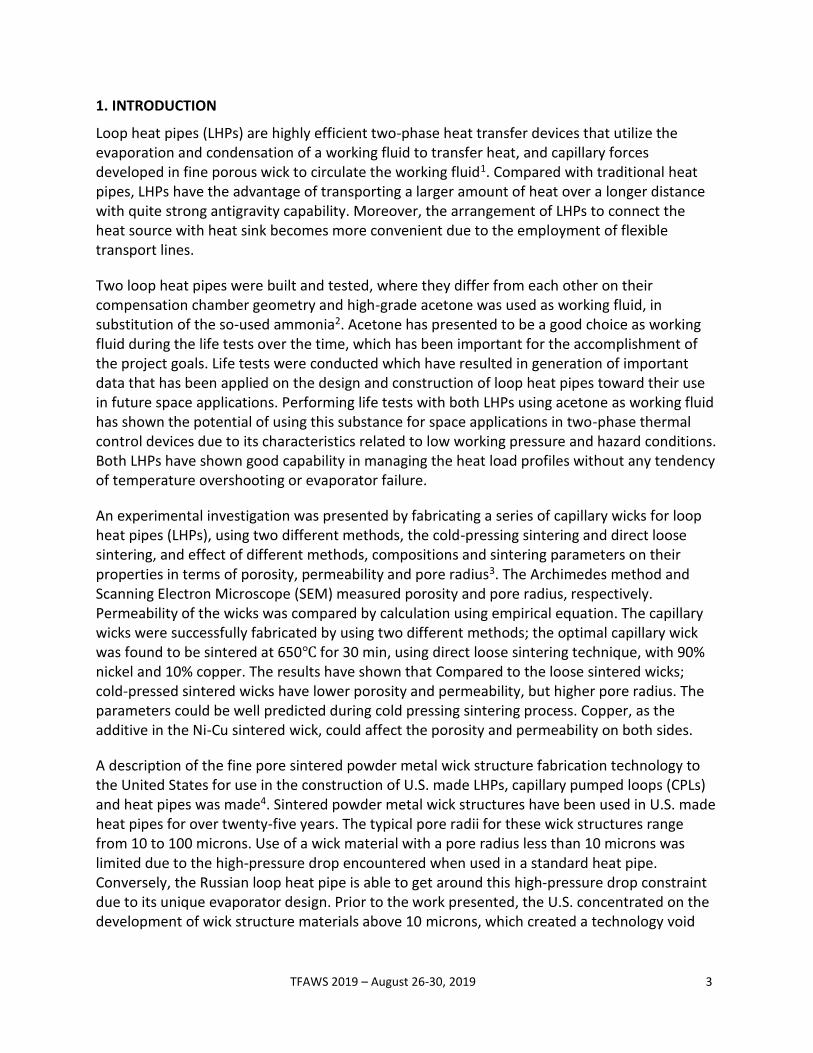
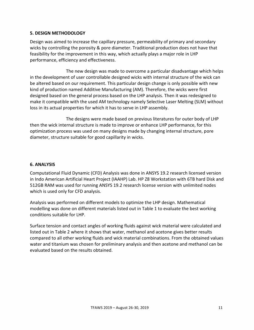
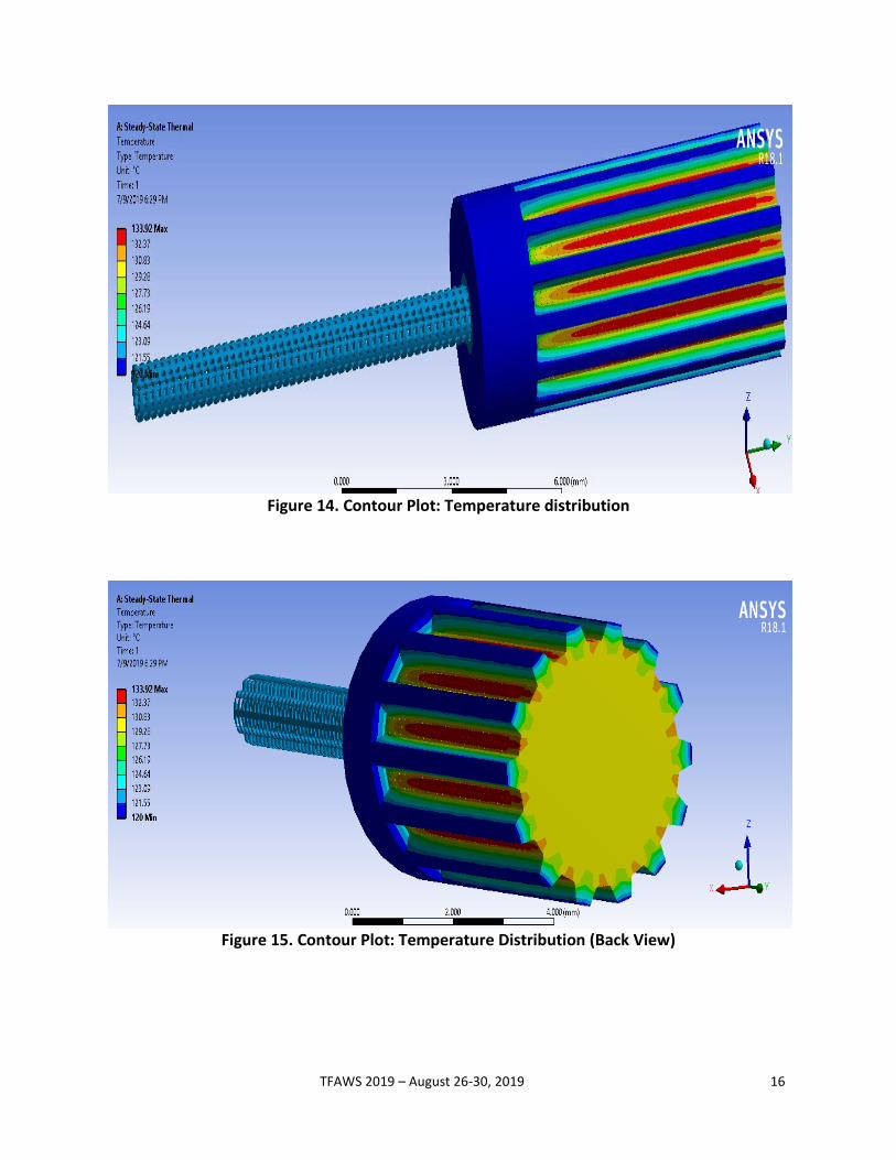
6.2 Thermal Analysis
Thermal analysis was done to evaluate the temperature distribution in different parts of LHP. Results show that there is heat leak into compensation chamber to reduce that the primary wick was designed in such a way that it reduces the heat leak from evaporation region to Compensation chamber. Final thermal analysis shown below gives a good result compared to previous designs.
Figure 12. Contour Plot: Total Heat Flux
Figure 13. Contour Plot: Total Heat Flux (Back View)
TFAWS 2019 – August 26-30, 2019 16
Figure 14. Contour Plot: Temperature distribution
Figure 15. Contour Plot: Temperature Distribution (Back View)

TFAWS 2019 – August 26-30, 2019 17
6.3 CFD Analysis
CFD analysis was made to study the fluid behavior and LHP performance under chosen best working conditions based on calculations from literature. Here the analysis is made for heat inputs of 80W, 100W and condensation is assumed ideal. Capillary pressure developed is calculated theoretically and is given as initial conditions for analysis, which is X Kpa. The model is Multiphase and the Evaporator material is stainless steel, Wick material is Titanium, Working Fluids are Water and Acetone.
Figure 16. Contour Plot: Density Distribution
Figure 17. Contour Plot: Density Distribution

TFAWS 2019 – August 26-30, 2019 18
Figure 18. Contour Plot: Temperature Distribution
Figure 19. Contour Plot: Fluid Velocity

TFAWS 2019 – August 26-30, 2019 19
Figure 20. Contour Plot: Pressure Distribution
Figure 21. Streamlines Showing Fluid Flow in Evaporator of LHP

TFAWS 2019 – August 26-30, 2019 20
7. FINAL OPTIMIZED DESIGN
Design was aimed to increase the permeability of primary and secondary wicks by controlling its porosity & pore diameter. Traditional production does not have that feasibility for the improvement in this way, which actually plays a major role in LHP performance, efficiency and effectiveness. The new design was made to overcome a particular disadvantage which helps in the development of user controllable wicks with internal structure of the wick can be altered based on our requirement. Production of this particular new design is only possible with AM. Therefore, the wicks were first designed based on the general process based on the LHP analysis. Then they were redesigned to make it compatible with the SLM production without losing their actual properties for which they have to serve in LHP assembly.
Table 4. Optimized Design Dimensions
S no NAME OF THE PART MATERIAL DIMENSIONS
1 Primary Wick Titanium Di=6, Do=14, pore dia (davg) =0.003, L=25
2 Secondary Wick Titanium Di=2.5, Do=6, pore dia (davg) =0.01, L=36
3 Evaporator Stainless Steel Di=14, Di=16.5, L=50
*(All Dimensions are in mm)
Figure 22. Primary Wick Figure 23. Primary Wick Isometric View

TFAWS 2019 – August 26-30, 2019 21
Figure 24. Secondary Wick
Figure 25. Evaporator Assembly

TFAWS 2019 – August 26-30, 2019 22
8. LHP PRODUCTION BY ADDITIVE MANUFACTURING (AM)
The traditional technology for the manufacturing of these wicks is sintering technique. Nevertheless, it presents the drawback of generating a random internal structure, which gives heterogeneity in the thermal -fluid behavior of the wick10. The use of an Additive Manufacturing (AM) technology Selective Laser Melting (SLM) can solve this problem, as it allows the user to take full control over internal structure of the wick.
Nevertheless, it presents the disadvantages of higher cost and suitable materials, although for the latter there are other 3D printing techniques, such as ‘‘Stereolithography”, ‘‘Digital Light Processing” and ‘‘Fused Filament Fabrication”. Still widely applied in many types of rapid prototyping techniques, stereolithography (SLA) was the first and the most accurate 3D process, as it can offer the finest surface finishes. The process involves turning a three-dimensional Computer Assisted Design (CAD) drawing into a solid object through the rapid and repeated solidification of liquid resin.
The key advantages of the SLM technique are that the developer enjoys an immense degree of geometrical freedom, without the limitations and constraints of other manufacturing methods11. Another advantage is that it is fully self-supporting; it allows parts to be built within other parts in a process called nesting with highly complex geometry that simply could not be constructed any other way. It is also possible to individualize the products and to enlarge the number of variations in arbitrary ways. The SLM process is a competitive alternative today, especially in areas where small batches of tiny components are required.
Table 5. Technical specifications of SLM machine (M 290)
Building volume 250 mm x 250 mm x 250 mm (9.85 x 9.85 x 12.8 in), including build plate
Laser type Yb-fiber laser; 400 W
Precision optics F-theta-lenses; high-speed scanners
Scan speed up to 7.0 m/s (23 ft/s)
Focus diameter 80-100 µm (0.004 in)
Power supply 32 A
Power consumption max. 8.5 kW / typical 3.2 kW
Compressed air 7,000 hPa; 20 m³/h (102 psi; 706 ft³/h)
Nitrogen generator integrated

TFAWS 2019 – August 26-30, 2019 23
Figure 26. EOS M290 DMLS machine Figure 27. 3D Printed Primary Wick
Figure 28. 3D Printed Secondary Wick Figure 29. 3D printed evaporator
Figure 30. 3D Evaporator Assembly

TFAWS 2019 – August 26-30, 2019 24
9. CONCLUSIONS
The overall performance of LHP mainly depends on design of Evaporator & Wicks. Mathematical modelling was performed on capillary wicks for operating conditions for a given heat load. The present design has shown good results when compared with the traditionally designed and manufactured LHP, there is a better agreement between design procedure and analysis results.
Thermal and CFD analysis results showed that the model can be used as a better device for future LHP design. Final design optimization was done based on these analysis results, which can serve the LHP purpose fully. Although LHP is designed for 8-10W of heat loads, it has showed a reliable operation for all heat loads. Further experimental tests are required for all other parameters with different working fluids like acetone, methanol that has shown good heat transport capability from analysis.
This particular design is easy to manufacture using SLM and can overcome problems during assembling of LHP as total assembly can be produced as a single product. The manufacturing cost for job production may rise high but when it is for a mass production cost is reduced compared to sintering.
FUTURE WORK
Experimental testing will be done to validate simulation results and theoretical results on new LHP design by manufacturing with SLM. Software will be developed to give out the best working LHP design for the given conditions. Parametric design of LHP Wicks will be developed, so that it will be easy to use for the coming generations.
ACKNOWLEDGEMENTS
Authors are very grateful to Dr. K. Eswaraiah sir and Dr. G. Ganesh Kumar sir for providing us with Indo American Artificial Heart Project (IAAHP) lab and their support during project.
CONTACT
Togaru Lavanith
Mechanical Engineer
+91 7780496301

TFAWS 2019 – August 26-30, 2019 25
REFERENCES
1. Y.F. Maydanik, Loop heat pipes, in: Applied Thermal Engineering 25 (2005) 635 – 657. 2. Roger R. Riehl a, Tulio C.P.A. Siqueira, Heat transport capability and compensation chamber
influence in loop heat pipes performance, in: Applied Thermal Engineering 26 (2006) 1158–1168.
3. XIN GongMing , CUI KeHang, ZOU Yong & CHENG Lin, Development of sintered Ni-Cu wicks for loop heat pipes, in: Sci China Ser E-Tech Sci | Jun. 2009 | vol. 52 | no. 6 | 1607 – 1612.
4. Nelson J. Gernet, Gregg J. Baldassarree and Joseph M. Gottschlich, Fine Pore Loop Heat Pipe Wick Structure Development, in: SAE International by University Of Newcastle, Thursday, August 09, 2018.
5. M. A. Chernysheva, S.V. Vershini, Yu. F. Maydanik, Operating Temperature and Distribution of Working Fluid in LHP, in: International Journal of Heat and Mass Transfer 50(2007), 2704–2713.
6. Gunnasegaran P, Abdullah M Z, Influence of Nanofluid on Heat Transfer in a Loop Heat Pipe, in: International Communications in Heat and Mass Transfer 47 pp. 82 – 91, 2013.
7. Ku, J., “Operating Characteristics of Loop Heat Pipes, in: SAE Paper No. 1999-01-2007, 29th International Conference on Environmental Systems, Denver, Colorado, July 12-15, 1999.
8. Ku, J., “Loop Heat Pipes Startup Behaviors, in: 46th International Conference on Environmental Systems, Vienna, Austria, 10-14 July 2016.
9. Y. F. Maydanik, Loop Heat Pipes - Development and Application, in: 7th International Heat Pipe Symposium (2003), Jeju, Korea.
10. R. Ranjan, J.Y. Murthy, S.V. Garimella, Analysis of the wicking and thin-film evaporation characteristics of microstructures, in: ASME J. Heat Transf. 131 (2009) 1–11.
11. B.P. Conner, G.P. Manogharan, A.N. Martof, L.M. Rodomsky, C.M. Rodomsky, D. C. Jordan, J.W. Limperos, Making sense of 3-D printing: creating a map of additive manufacturing products and services, in: Additive Manuf. 1 (2014) 64–76.