design of tema type e 779 shell computer-id … · shell and tube heat exchanger ... and...
TRANSCRIPT
= RD-R53 779 COMPUTER-ID ED THERMOYDRULIC DESIGN OF TEMA TYPE E
1/2 7'SHELL AND TUBE HEAT..(U) ARMY MILITARY PERSONNEL CENTERALEXANDRIA VA N J KOLAR 81 APR 85
UNCLASSIFIED F/O 13/1 ML
. -. Q
ILL
11111 L Nm22
MICROCOPY RESOLUTION TEST CHARTNATIONAL BUJREAU Or STANDARDS-19W A

L%
SECURITY CLASSIFICATION OF THIS PAGE (When Date Entered) _
1. REPORT NUMBER 2 OVT ACCESSION NO:-'-RCPETSCTLGNME
4. TITI F (mn' Rttte) 5. TYPE OF REPORT & PERIOD COVEREDComputer-aided thermohydraulic design of TEMA typE Final Report
E shell and tube heat exchangers for use in low 1 April 1985pressure, liquid to liquid, single phase 6. PERFORMING ORG. REPORTNUMBER
applications.
7. AUTHOR(e) 8. CONTRACT OR GRANT NUMBER(e)
i n CPT Nicholas J. Kolar
9. PERFORMING ORGANIZATION NAME AND ADDRESS 10. PROGRAM ELEMENT. PROJECT, TASK
Student AREA & WORK UNIT NUMBERS
HODA, MILPERCEN (DAPC-OPA-E)200 Stovall Street Alexandria, Va. 22332
1I1. CONTROLLING OFFICE NAME AND ADDRESS 12. REPORT DATE
HODA, MILPERCEN,ATTN: DAPC-OPA-E 1 April 1985200 Stovall Street 13. NUMBER OF PAGES
Alexandria, Va. 22332 16814. MONITORING AGENCY NAME & ADDRESS(If different from Controlling Office) 15. SECURITY CLASS. (of this report)
15e. DECLASSIFICATION/DOWNGRADINGSCHEDULE
16. DISTRIBUTION STATEMENT (of this Report)
Approved for public release; distribution unlimited.
MY 117. DISTRIBUTION STATEMENT (of the abstract entered In Block 20, if different from Report) M 1 18
IS. SUPPLEMENTARY NOTES
Document is a thesis from Bucknell University, Lewisburg, Pa. 17837.
19. KEY WORDS (Continue on reverse side if neceesary nd identify by block number)
Shell and tube heat exchanger designComputer-aided design
.., 20. ABST'RA Ct (cmfIjen re e rWa eawa md Idenitif by block number)
Classification, nomenclature, utilization and cost estimating of shell and
'[ tube heat exchangers are presented along with an historical overview of variousmethods currently employed in their design.
A procedure for providing estimates of shell and tube heat exchanger designis developed in detail along with a computer program which employs this sizingalgorithm for low pressure liquid-to-liquid exchanger applications.
" . Additionally,problems encountered in the design and manufacture of shell and
DD t Si73 147I EWrTIO14 OF I NOV 6S IS OBSOLETE
SECURITY CLASSIFICATION OF THIS PA7,E (When Dete Fw-ed)

SECURITY CLASSIFICATI N OF 1 HIS PAGE(When Data Entered)
continued from block 20;
tube heat exchangers are described along with present methods of solution foreach.
SECURITY CLASSIFICATION OF THIS PAGE(i"en Data Entered)
k~.. . .
COMPUTER-AIDED THERMODYNAMICS DESIGN OF TEMA TYPE E - -SHELL AND TUBE HEAT EXCHANGERS FOR USE IN LOW PRESSURE,
LIQUID-TO-LIQUID, SINGLE PHASE APPLICATIONS
CPT Nicholas J. KolarHQDA, MILPERCEN (DAPC-OPA-E)
200 Stovall StreetAlexandria, VA 22332.-- " . -
FINAL REPORT 1 APRIL 1985
Approved for Public Release; distribution is unlimited
A thesis submitted to the faculty of Bucknell University inpartial fulfillment of the requirements for the degree of
Masters of Science in Mechanical Engineering.
. . . . . . . . . . . .. . .~. . . .-.. . '

1, Nicholas J. Kolar, do grant permission
for my thesis to be copied.

COMPUTER-AIDED THERMOHYDRAULIC DESIGN OF TEMA TYPE E
SHELL AND TUBE HEAT EXCHANGERS FOR USE IN LOW PRESSURE,
LIQUID-TO-LIQUID, SINGLE PHASE APPLICATIONS.
BY
NICHOLAS JOHN KOLAR
PRESENTED TO THE FACULTY OF
BUCKNELL UNIVERSITY
IN PARTIAL FULFILLMENT OF THE REQUIREMENTS FOR THE DEGREE OF
MASTERS OF SCIENCE IN MECHANICAL ENGINEERING
APPROVED: / ?.' 2 Ait
UI Advisor
Departm C airperson
1 April 1985
................................................................... . -.-................................................................... . .•

ACKNOWLEDGEMENTS
The writer is especially indebted to the following individuals:
My advisor, Professor J. Ben Austin, Jr., for his instruction,
suggestions and advice.
Professors Charles H. Coder, James N. Zaiser, and Thomas P. Rich for
their encouragement and advice.
Mr. A. Tim Chase, Manager Special Products Division of Struthers
Wells Corporation and Chairman of TEMA Technical Committee, for his
professional critique, in-depth discussion of current shell and tube
heat exchanger design, and detailed tour of the Struthers Wells
Manufacturing facilities.
Ms. Christa Decker for her cooperation and expert assistance in the
use of the CAED Laboratory.
Ms. Kimberly Lazar for her cheerful and exceptionally efficient
typing of this thesis.
Lastly, but by no means the least, my family, and in particular my
wife Barbara, whose understanding, consolation and encouragement has
been both loving and unswerving.
. . . '
TABLE OF CONTENTS
Page
1. Introduction . . . . . . . . . . . . . . . . . . . . .
11. Basic Components of Shell and Tube Heat ........ 3
Exchangers
A. General .. .. ...... .. .. .. ...... 3
B. Tubes . . . . .. .. .. .. .. .. .. .. .. 3
C. Tubesheets .. ... ......... . .. .. . .3
0. Shell . . . .. .. .. .. .. .. .. .. .. .. 5
E . Shell Nozzle . . . . . . .. .. .. .. .. .. .. 5
F. Tube-side Channels and Nozzles. .. ..... .... 5
G . End Covers. .. ..... ...... .. .. .... 5
H. Pass Partition Plate . . . .. .. .. ..... 6
I. Baffles . . .. . . . . . . .. .. .. .. .. . .6
111. Codes and Standards .. ... ....... ....... 9
A. General . ... .. .. ... ..... .. .. ... 9
B. ASME Boiler and Pressure Vessel Code .. .. ......9
C. Foreign Pressure Vessel Codes . . . .. .. .. .. 9
D. ANSI Standards .. .. ..... ....... .... 10
E. API Standards. .. ..... ....... ..... 10
F. HEI Standards . .. .. .. .. .. .. .. .. . .10
G. TEMA Standards .. .. ..... ....... .... 10
IV. Design Techniques. .. ..... ...... .. .. .. 13
A. General...... ... . . .. .. .. .. .. .. . . . 13
B. Delaware Method. .. ...... .... . . . ... 15
C. Bell Method. .. ...... ...... ...... 15
iv.. ..VP
TABLE OF CONTENTS (CONT'D)
Page
D. Tinker Method . . ... . . . ... . .. .. . 16
E. Devore Method . . . . .. . ........ . . . . . 19
F. Numerical Methods . . .... . ............ ..... 19
G. Proprietary Programs ..... ........ . 20
V. Shell and Tube Exchanger Utilization. .......... . 23
VI. Problems Encountered in Shell and Tube Heat Exchanger . 24
A. General ........... ...................... 24
B. Flow Induced Vibrations ........ .............. 24
C. Fouling ............. . ........ 25
V[[. Computer-Aided Design Procedure . ...... ........... 28
A. General............... . . . . . . . 28
B. Instructions ...... .................... .28
C. Input Data ..... .................. . . . 29
D. Number of Tubes Calculations ............ 31 ... .. .
E. Available Tube Surface Area .... .......... . 35
F. Maximum and Minimum Tube-Side Flow Rates ........ 35
G. Maximum and Minimum Shell-Side Flow Rates . . . .. 37
H. Thermo-Hydraulic Properties of the Tube Fluid . . . 39
I. Shell-Fluid Exit Temperature Determination ... . 40
J. Calculation of Maximum and Minimum Capacity Rates . 41
K. Heat Transfer Effectiveness Calculation . . . . .. 42
L. Determination of Number of Transfer Units . . ... 42
...................................... . -
vJ
TABLE OF CONTENTS (CONT'D)
Page
M. Calculation of Estimated Overall U-Value ......... 43
N. Determination of Possible Exchanger . ....... 45
Configurations
0. Output of Possible Exchanger Configurations . ... 56
P. User Selection of Possible Exchanger ........... 57
Configurations
Q. Calculation of Estimated Capital Cost ... ....... 57
R. Final Design Output . ............... 59
S. User Directed Changes to Input Parameters ....... 60
Vil. Example Problem ............ ........ 61
IX. Computer Results ........................ 62
X. Conclusion ........ ... ............ 77
A. Discussion ....... ..................... 77
B. Suggestions for Improvement ... ............ .78
XI. References ...... ....................... .79
XII. Appendix A: Variable Listing
Appendix B: Main Program Listing
Appendix C: Fluid Property Subroutines (Water Only)
Appendix 0: PRESCK Subroutine
Appendix E: TFRICT Subroutine
Appendix F: SFRICT Subroutine
Appendix G: Print Subroutines
'--'- . ..J" ' ' ' ... ... . ,.' -- w.b .. -:.'...... - . -. " " " '" •"-."-.- "- •.-" " - '

vi
LIST OF FIGURES
Figure Page
1 Diagram of Typical Fixed Tube Sheet Heat Exchanger... 4
2 Partition Plate Configurations .... ............. 7
3 Baffle Configurations ................. 8
4 TEMA Type Designations .... ................. .12
5 Leakage Paths for Flow Bypassing the Tube Matrix. ... 14
6 Bell Method Design Chart .... ................ .17
7 Standard Tube Layout Designs ..... .............. 32
8 Effectiveness - NTU Chart for a 1-2 Exchanger ....... 44
Table Page
1 Typical Overall Design Coefficients for Shell ....... 46
and Tube Heat Exchangers
vii
I
ABSTRACT
Classification, nomenclature, utilization and cost estimating of
shell and tube heat exchangers are presented along with an historical
overview of various methods currently employed in their design.
A procedure for providing preliminary estimates of shell and tube
heat exchanger design is developed in detail. The author formulates a
computer program which employs this sizing algorithm for low pressure
liquid-to-liquid heat exchanger applications.
Additionally, problems encountered in the design and manufacture of
shell and tube heat exchangers are described along with present methods
of solution for each.
. . . . . . . .. . . . . . . . . . . . . . . . . . . . . . . . . . . .
I. INTRODUCTION
In the most basic terms, a heat exchanger is a device which provides
for the transfer of thermal energy between fluids at different tern- - -
peratures. Since high energy costs reduce profit margins of industrial
products, any means of recovering by-product thermal energy, may result
in an increase in corporate gains. For this reason, heat exchangers of
all shapes, sizes, and configurations can be found throughout a wide
range of industries.
Because of several factors which include: large ratios of heat
transfer area to volume and weight, ease of construction and main-
tenance, design flexibility, and availability of proven design method-
ology, shell and tube heat exchangers are the most widespread and
commonly used basic heat exchanger configuration in the process
industries.[1]* It is with this in mind that shell and tube heat
exchangers were chosen as the subject for this computer-aided design.
It should be noted that the design of a shell and tube exchanger
consists of two basic areas. The first is the thermal-hydraulic design,
which considers process fluids, flow arrangements, fluid flow rates,
inlet and outlet fluid temperatures, fouling factors, pressure drops,
)nstruction materials and overall dimensions to ensure that the design
allows for the ther:mal energy transfer required in the probleni. The
second is the mechanical design of the heat exchanger which ensures the
mechanical integrity of the exchanger components during its operation.
Pressure stresses and thermal stresses must be evaluated for each inte-
gral component, along with other considerations such as methods or
* Numbers in the [ ] bracket indicate sitings in the References.
............... mdammlm .'m............ tm-". .. " " . .j

15
B. Delaware Method
Probably the most widely publicized research program in the area of
shell and tube heat exchanger design was an ASME sponsored project
undertaken at the University of Delaware from 1947 to 1963. Under the
auspices of Professors Olaf Bergelin and Allan Colburn, the Department
of Chemical Engineering did extensive experimental measurements of
shell-side heat transfer and pressure drop for different configurations
of shell and tube heat exchangers. Systematically, baffle spacing,
baffle-to-shell clearances, and tube-to-baffle clearances were adjusted
to measure their effect on the shell-side performance characteristics.
The Delaware Project produced several technical papers, and provided
invaluable experimental data. One quantitative result of the project
was an equation for the heat transfer coefficient which includes five
correction factors to the ideal cross-flow heat transfer coefficient.
Another, was an equation for the shell-side pressure drop which includes
three correction factors to the ideal pressure loss of a shell with no
leakage or bypass.
It must be noted, that although this method is generally accepted to
be the best available in the open literature, it is not extremely
accurate. Tests have shown that this method predicted shell-side heat
transfer coefficients from about 50 percent low to 100 percent high, and
the predicted shell-side pressure loss was fron about 50 percent low to
2P0 percent high.[10]
C. Bel l Metnod
Professor Kenneth J. Bell from Oklahoma State Uni versity devised a
method for preliminary design of shell and tube heat exchangers which
. .-... . ... ., ............. . ....,........... ........ . .. ............. . . ..

14
FIGURE 5
LEAKAGE PATHS FOR FLOW BYPASSING THE TUBE MATRIX
c00000D00 '00000 wco
FRONT VIEW
SIDE VIEW

13
IV. DESIGN TECHNIQUES
A. General
The most dynamic period of development in heat transfer occurred
between 1920 and 1950. During this period almost all of the principles
of thermodynamic behavior of heat exchangers became understood. One
book, which was published after this important technological period,
stands alone in the design of shell and tube heat exchangers. The book,
Process Heat Transfer, by Donald Q. Kern, a professor from Case
Institute of Technology, has provided the methods and procedures for the
design of more shell and tube heat exchangers than any other single
source.[8]
Probably the most difficult design parameters to quantify are the
shell-side performance characteristics. Ideally, the shell-side flow
can be viewed as a cross flow of fluid across a bank of tubes. But in
reality, the flow goes both across the tubes and parallel to the tubes
due to the serpentine motion of the fluid caused by the internal baffles
of the exchanger. This is further complicated by leakage which occurs
due to gaps between the baffle and the shell and spaces between the
baffle and the tubes. This leakage or bypass flow causes a decrease in
the heat transfer coefficient and uncertainty in the shell-side pressure
drop. A diagram of the leakage paths taken from Reference 9 is shown in
Figure 5. The elusive shell-side performance characteristics have been
the cause for many independent studies, ultimately resulting in innova-
tive methods for design.

12
FIGURE 4
TEMA TYPE DESIGNATIONS
PPONT END oAR END
STATIONARY PEAD TYPES SHL YE PES
El Lj LI~ ' TAS SHEET
ACNE PA5 HELL KE A7",A' -Y HEAD
CH AAND ATE0V1.IE CCO'FR F LJ
BF ;D ii E- EIT TE3:---S '- LLLKE 3' -7,' Y HEAD
SNNETINIE-RALCCVE) STT TH
C,__ OUT~D PNKD LATN HEAD
C NNET TINIE(-AL WIT TER SPI -,)
SHEET AN LLDCVAPACKED E J I ~fA'NGHHAA
,-',g SPLIT FAKN ~ 'CBU I to
C-HANNEL INTE -AL WITH TUBE-IHI-ET AND -ECV-t' E COVED
r COA!N HEAD
* I ii- BACKINGr DEVICD
SPE-CAL HIGH PPE~3LRE C:C~jRE CROSS Flow 'I A L . J L H E
T-N

and abroad. It has proven successful over the years because it is based
on sound engineering practice. Probably most iotable is the standard-
ization of size designation and nomenclature which is used throughout
the industry. Figure 4 shows the standard letter designations for the
stationary head types, shell types, and rear-end head types. The
program presented in this thesis designs TEMA "E" shell configurations.
TEMA standards require that ASME codes are followed. TEMA does
cover internal components where ASME code rules are not available or are
not applicable. In essence, TEMA provides good solid design and
construction rules for heat exchangers considered as a special type of
pressure vessel.
Three different classes of heat exchangers are developed in detail.
Class "R" - Shell and tube heat exchanges which must 'feet the
severe requirements of the petroleum industry.
Class "C" - Shell and tube hM exchangers which must ineet the
moderate requirements of commercial and general pro-
cess applications.
Class "B" Shell and tube heat exchangers which nust !neet the
requirements of chemical process service.
For each classification, TEMA sets the standards for design for each
of the integral parts of the heat exchanger. These include: tubing,
shells, baffles, heads, gaskets, tubesheets, channels, nozzles, end
covers and bolting.
Additionally, TEMA provides information on generally used materials,
fouling resistances and physical properties of fluids. General infor-
nation such as characteristics of tubing, metal properties and conversion
factors are also provided.
.-. -. -*..../ .* ... ..-.. .....-.... •.......... ..... "-.. *.
10
There is presently international interest in developing a code which
will provide rules for use on an international basis. There are several
major obstacles to its development including safety factors and material
speci ficati ons.
0. American National Standards Institute (ANSI) Standards
ANSI is a Federal organization which manages standards throughout
the United States. The ASME Code is an ANSI standard. A particular
ANSI standard that is not covered by any other code is on that deals
specifically with chemical processes.
E. American Petroleum Institute (API) Standards ..
API standards deal specifically with shell and tube heat exchangers
which are used in connection with oil refinery services. The standards
have been developed over the years from the accumulated knowledge and
experiences of petroleum refiners nationwide.
F. Heat Exchange Institute (HEI) Standards
The HEI organization has developed standards for heat transfer
equipment for use in steam power plants. Particular areas include:
standards for closed feedwater heaters, standards for power plant heat
exchangers (electric generating plants), and standards for steam surface
condensers.
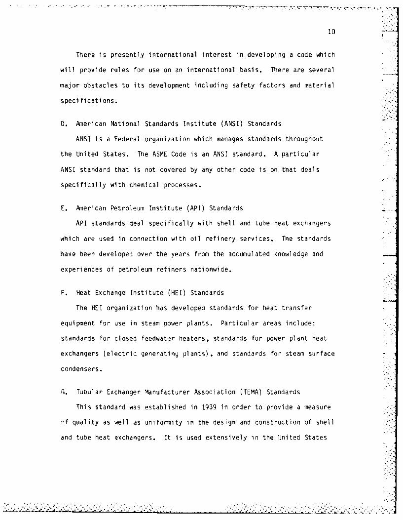
G. Tubular Exchanger Manufacturer Association (TEMA) Standards
This standard was established in 1939 in order to provide a measure
-f quality as well as uniformity in the design and construction of shell
and tube heat exchangers. It is used extensively in the United States
. . ----.-. .- -. .. - - -. ... , .. ....-.. - ... .- ,. .. ..................... . .. ..... . .' . ........

9
III. CODES AND STANDARDS
A. General
Shell and tube heat exchangers are the most versatile and most
widely used type of heat transfer equipment. Units can be designed to
handle sensible heating, condensing and boiling. Operating pressures
range from near vacuum to above 5800 psi. They may weigh as much as 200
metric tons and encompass as much as 50,000 ft2 of heat transfer surface
area.[7] To find codes and standards for its complex design, one needs
to go to several different sources.
B. American Society of Mechanial Engineers (ASME) Boiler and Pressure
Vessel Code
A shell and tube heat exchanger is indeed a pressure vessel and
therefore must comply with several sections of this code which apply to:
power boilers, material specifications, nuclear power plant components,
nondestructive examination, pressure vessels, and welding and brazing
qual i fications.
In the United States and Canada, the ASME code is recognized as the
means by which control over the design, fabrication and testing of
boilers and pressure vessels is achieved.
C. Foreign Pressure Vessel Codes
Most major industrial countries such as France, Great Britain, and
West Germany have their own boiler and pressure vessel codes. Normally,
if a unit is to be placed in service in one of these countries, their
standards and limitations must be adhered to.
. -.. . .*

8
FIGURE 3
BAFFLE CONFIGURATIONSI
SINGLE SEGMENTAL
DOUBLE SEGMENTAL
TRIPLE SEGMENTAL
A
TUBED AREA
SEGMENTAL - NO TUBES IN WINDOW
DISK AND DONUT
. . . . . . . .. .. .

77 7 -.7 .7- 70-
7
FIGURE 2
PARTITION PLATE CONFIGURATIONS
3
FRONT REAR
22
TWO TUBE PASSES
3 2 3 2
4 4
FOUR TUBE PASSES
3 2 3.
4 5 4 5
6 6
SIX TUBE PASSES
e3 22
4 5 4 5
8 8
EIGHT TUBE PASSES
...............-... ............-. ,.. .;,......,. .. ,.......... ..... .. . . .. ..... .. .. :... . .. .. .-..- , ,.: i

6
The most common configurations are: one shell pass two tube passes,
one shell pass four tube passes, one shell pass six tube passes, and one
shell pass eight tube passes. In these multiple-tube pass heat
exchangers, pass partitions are required in the tube-side chambers of
the heat exchanger to direct the flow of the tube fluid. The arrangement
of the tube-side pass partitions affects the heat transfer behavior of
the heat exchanger, and obviously affects the placement of the tube
fluid entrance and exit nozzles. The most common tube-side pass par-
titions are shown in Figure 2.[3,4]
I. Baffles
The interior baffles of the heat exchanger serve two important fjnc-
tions. First, they support the tube bundle keeping the proper tube
spacing during both construction and operation and at the same time pre-
vent unwanted vibration in the tube bundle. Secondly, they provide a
path for the shell-side fluid to move back and forth across the tube
bundle increasing the shell-side fluid velocity and also increasing the
heat transfer coefficient.
Several of the baffle configurations that are in use today are
shown in Figure 3. The most common (and the one that this computer-
aided design program is based upon) is the single segmental. The
segment sheared off must be less than 50 percent and for liquid to
liquid applications, a baffle cut of 20 - 25% is common.[6]
.. . . . . . . . . ..
. . . . . . . . . .
:'Li~~~ ~ ~~. . . . . . . . ..... ..-.-. .'---..'."'";'''" .1: ""'" : '""-'L ."..- ,".."-. .""."'- '1" .' - -'- . '. tA-': .' 'A ',';'':'-''; :'':' "- ':" ' ":

5
are: roller expansion of the tube into ungrooved tubesheets, hydraulic
expansion of the tubes into grooved tubesheets, and welding the tube
ends directly to the tubesheets.
0. Shell
The shell is a cylindrical vessel which holds the shell-side fluid.
In small diameter shells (less than 24 inches), the shell is cut from
standard pipe. For larger diameter shells, the shell is fabricated from
rolling metal sheets of the desired dimensions and longitudinally
welding the butt joint.
E. Shell Nozzle
The shell has two nozzles which allow for the entrance and exit of
the shell-side fluid. The inlet nozzle normally also has an impingement
plate which prevents the incoming fluid stream from impacting directly
upon the exposed tubes causing unwanted erosion and vibration.
F. Tube-side Channels and Nozzles
The tube-side channels and nozzles direct and control the flow of
the tube-side fluid when it is not in the tubes of the heat exchanger.
G. End Covers
The end covers are metal plates that normally are bolted onto the
ends of the shell. They are bolted rather than welded to facilitate
maintenance and inspection of the tubes and channels in the heat
exchanger.
H. Pass Partition Plate
The fluid in the tubes may travel the length of the exchanger more
than one time. These are heat exchangers with -nultiple tube passes.
4
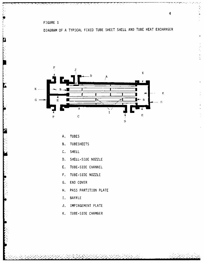
FIGURE 1
DIAGRAM OF A TYPICAL FIXED TUBE SHEET SHELL AND TUBE HEAT EXCHANGER
FJ
Ii E
D A
I~~i r I I -... K
A. TUBES
B. TUBESHEETS
C. SHELL
D. SHELL-SIDE NOZZLE
E. TUBE-SIDE CHANNEL
F. TUBE-SIDE NOZZLE
G. END COVER
H. PASS PARTITION PLATE
I. BAFFLE
J. IMPINGEMENT PLATE
K. TUBE-SIDE CHAMBER

3
II. BASIC COMPONENTS OF SHELL AND TUBE HEAT EXCHANGERS
A. General
For the purpose of establishing standard terminology, Figure 1
illustrates several basic componer. _" of shell and tube heat exchangers
which will be described later. Even though there are thousands of spe-
cific design features that can be used, these specific components will
invariably be present in all shell and tube heat exchangers.
B. Tubes
The tubes are the most basic component of the shell and tube heat
exchanger. The tube wall provides the heat transfer surface between the
fluid flowing inside the tube and the fluid flowing inside the shell.
The tubes can be either seamless or welded. The metals used are carbon
steel, low alloy steel, stainless steel, copper and copper alloy, nickel
and nickel alloy, aluminum and aluminum alloy, titanium and zirconium,
although special metals may be used to meet specific applications.[2]
The tubes may be bare or have integral circumferential finning. The
computer-aided design program formulated in this thesis assumes that the
tubes used are bare. The assemblage of all the tubes in the heat
exchanger is referred to as the tube bundle.
C. Tubesheets
The tubes of the exchanger are held in place by being inserted into
holes in metal sheets at either end of the shell. They are fixed in
place by a variety of methods. The tube to tubesheet joint has the
single objective of sealing against interleakage between the tube-side
and shell-side fluids. Common methods of joining the two components
-.- c.-- ...- * ..~-.-- :........

2
bonding components, types and sizes of gaskets and seals, and minimiza-
tion of flow induced vibrations. This thesis covers only the thermal-
hydraulic design of the heat exchanger. Although equally importdnt as
the thermal-hydraulic design, the mechanical design is much 'fore intri-
cate and has been left to those who are most capable of accomplishing
the task - namely, the shell and tube heat exchanger manufacturers of
the United States and abroad. For it is their decades of experience,
experimentation, and research that has developed the standards of
construction and manufacture that are in use today.
.. . . . . . . . . .
. . . . . . . . .

16
also takes into account deviations from ideality. His method is unlika
the Delaware method in that he does not directly calculate the shell-
side heat transfer coefficient. He uses typical overall design coef-
ficients (U-valves) for shell and tube heat exchangers depending upon
the type of fluids that are used. The data has been collected from
years of experimental performance and commercial usage. Using this
overall design coefficient, Bell calculates the required outside tube
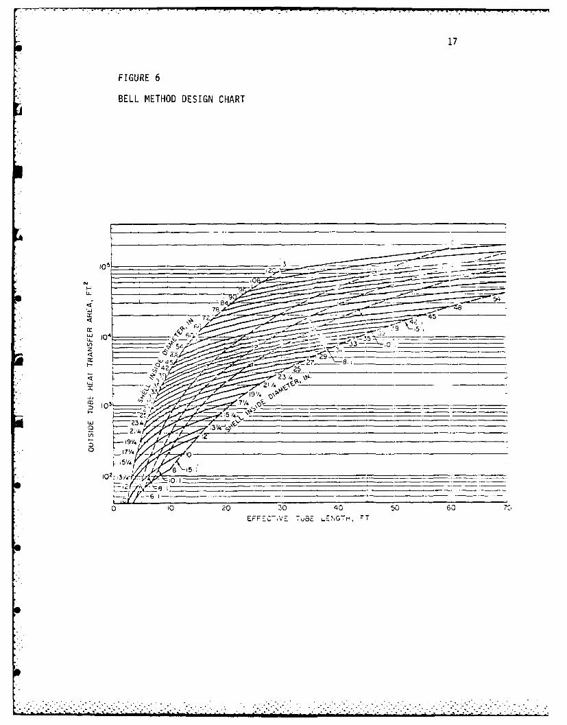
heat transfer area. The key to the Bell Method is the graph shown in
Figure 6. Bell has depicted on this graph the possible configurations
of shell and tube exchangers using standard tube counts for 3/4 inch
0.0. tubes on a 15/16 inch triangular pitch for a fixed tube sheet
exchanger with one tube-side pass. Also shown are the effective tube
length to shell diameter ratios (3:1, 5:1, etc.) available. The user
simply enters the ordinate of the graph with the required area and imme-
diately knows the combinations of tube length and shell diameter that
will provide that area in a single shell for an exchanger of Bell's
standard tube size and layout. For those exchangers that do not conform
to Bell's standard, three correction factors to the area calculation
are utilized; one for different tube diameters and layouts, one for dif-
ferent numbers of tube-side passes, and one for different TEMA tube
bundle construction types. The Bell Method is used solely for prelimi-
nary estimates of the heat exchanger size, and is obviously not a
complete design methodology.
0. Tinker Method
In 1951 Townsend Tinker, vice-president for engineering of Ross Heat
Exchanger Division, American Radiator and Standard Sanitary Corporation
........................
+%. - --. 2 .'. .'. .....". .' '.-.-.-. . . ..--. . . . . . ..'... . .... .. -. ' " -. -. i - - 2 :- i .. - .- . i - i- . i' - '. 2 ,i i~ l .i - ? i .. . '- 2 ~ i . . - i
17
FIGURE 6
BELL METHOD DESIGN CHART
10
eH
U-4
42- 25
4~ /- 11 .k-Z----
23. A

18
was the first to develop a complex but effective methodology for
including the effects of deviations from ideality. The fluid streams in
the shell depicted in Figure 5 was taken from his original work. Tinker
uses graphs of modified shell-side Reynolds numbers vs. shell-side fluid
friction factors and modified shell-side Reynolds numbers vs. shell-side
heat transfer coefficients for three different tube-hole patterns:
triangular pitch, square pitch and staggered square pitch. The experi-
mental data he uses comes from the research done by the Delaware
Project.
While Tinker's basic derivations are general, they are cumbersome
unless the range of possible combinations of his geometric parameters is
reduced. He does this by adopting representative values for three
geometric ratios: the ratio of the clearance between the tubes and
holes in the baffles to the tube outside diameter, the ratio of the
clearance between the baffle and the shell to the shell inside diameter,
and the ratio of the shell inside diameter to the outside diameter of
the tube bundle. These ratios are closely related to the various bypass
flow streams shown in Figure 5 and are kept as small as possible, con-
sistent with fnanufacturing tolerances and the clearances required for
assembly.
Once these ratios are fixed, Tinker showed that the various bypass
flow rates become functions of five more geometric ratios: the ratio of
the shell diameter to the tube length between baffles, the ratio of the
tube pitch to the tube length between baffles, the ratio of the tube
pitch to the tube outside diameter, the ratio of the baffle height to
the shell diameter, and the ratio of the number of rows of tubes tra-
versed per pass to the shell inside diameter divided by the tube pit:h.
p. • .
t'. " . * - " - " " - " "" • " * - ". . -. ' ° ' " " " -

19
The modifications to the Reynolds number are made using correction
factors which depend upon the various clearance ratios previously cited.
Once the modified Reynolds number is calculated, the heat transfer coef-
ficient and shell-fluid friction factor can be determined from the
appropriate chart.
As one would suspect, Tinker's calculated values, with their many
complex relationships, have been proven to be as much as 50 percent
deviant from the experimentally determined values. Tinker was however,
the forerunner in this area, and his published works have stimulated
many advances in this area.[11,121
E. Devore Method
Anthony Devore used the basic method of Tinker but made several
simplifications. First, he used standard tolerances for commercial
exchangers in lieu of certain of Tinker's geometric ratios. Second, he
limited the number of baffle cut ratios. Lastly, he provided several
charts and tables for easy determination of correction factors. The
results are even more conservative than those obtained via Tinker's
original method.[13]
F. Numerical Methods
The most promising method of calculating the design parameters for a
shell and tube heat exchanger stems directly from sophisticated
computer-based numerical procedures for calculating fluid-flow distribu-
tions. Shell and tube exchanger geometries necessitate a three-
dimensional procedure. Three velocity components have to be computed
for the shell fluid at each point. Furthermore, the lack of any axial
symmetry causes these velocities, as well as the temperatures and
.- . . - .. , - , . , . - - .~
, . • . . - , o . . . o o o - - .

20
pressures, to vary throughout all three space dimensions. The solution
to the differential equations which govern the flow of a continuous
fluid can be accomplished by using a finite-difference approach.
Alternately, the space within the shell can be regarded as uniformly
filled with fluid, through which is distributed, on a fine scale, a
resistance to fluid motion.
This alternate continuum approach has two advantages. First, it
allows the use of a grid which is less fine than the finite-difference
approach, with a savings in computer time. Second, it allows for the
use of the extensive experimental data that is available on the
pressur_-drop and heat transfer performance of fluid flow through tube
banks. The results of this type of computer-based numerical method is
an increased realism of the predictions of the pressure drop and heat
transfer coefficient.[14]
r, . Proprietary Programs
During the boom years of heat transfer development, universities and
industries worked hand in nanJ to solve heat transfer problems. Since
that time, the emergence of the new fields of nuclear energy and
aerospace flight coupled with the revolutionary computational power made
available by high-speed digital computers caused a partial disjunction
between this university-industry fellowship. Professor Thomas Sherwood
from the Massachusetts Institute of Technology describes it in these
words:
...Prior to World War II the emphasis at universities
was on the collection and correlation of data intended
to be of direct use by the practicing design engineer.
21
Industry had few such data and published little, so
schools felt a responsibility to fill the need. This
urge to be immediately helpful to industry has largely
disappeared today; research in schools is now along
more scientific and theoretical lines, hopefully of
value to industry a generation hence. Our rapport with
industry has suffered.[15]
The new fields of nuclear energy and aerospace flight transfused
research funds of unprecedented magnitude into the laboratories and
research institutes. The results of this expanded research had, unfor-
tunately, little applicability to industrial needs.
The computer's mammoth capabilities enabled theorists and design
engineers alike to solve the heat transfer problems using numerical
methods that were abandoned in the boom years due to their computational
sophistication. Computer programs were rapidly developed and the need
for the university's experimental data ebbed.
What evolved to take the place of university research were organiza-
tions that did private research for tne benefit of the members of their
consortium. Their experimental data along with their computer source-
codes were proprietary. The suppression of publicly available infor-
mation and experimental data was widespread, and today the effects of -
this lack of scholarly interchange cannot really be discerned.
In the area of heat transfer, one organization in particular stands
out as being the most knowledgeable in the field. Heat Transfer
Research Incorporated (HTRI) in Alnambra, California, has developed the
most sophisticated software in use today in the design of shell and tube

22
heat exchangers. The majority of the shell and tube heat exchanger
manufacturers use their programs, such as ST-4 to compute the heat
transfer characteristics and pressure drops in their heat
exchangers .[16,17]
.i~
-i -
. . .. . . . . ..

23
V. LIQUID-LIQUID SHELL AND TUBE HEAT EXCHANGER UTILIZATION
Because shell and tube heat exchangers can be constructed with very
large heat transfer surfaces in relatively small volume, can be fabri-
cated fron alloy metals to resist corrosion and can be used for heating
and cooling virtually all fluids, they are universally accepted as the
most important class of heat transfer equipment.[18]
From cooling chemical solutions in world-class chemical processing
plants to heating water for a backyard swimming pool, applications for
liquid-liquid shell and tube heat exchangers abound. The nuclear
industry uses them to cool heavy water in ato.nic reactor installations.
The metallurgical industry uses them to cool quench oil. The Food
Processing industry uses them for vegetable oil heaters and dairy pro-
duct coolers. The petroleum industry uses them to cool oil used in
machine lubrication on offshore oil platforms by using sea water as the
cooling medium. Local schools may use them to preheat low-grade fuel
oil. The list of applications will be as long as the imagination of the
design and process engineer is broad.[19,20]
Virtually all industries that produce a waste or by-product fluid
stream that has an exit temperature higher thal the inlet fluid tein-
perature can use a liquid-liquid shell and tube heat exchanger to
recover some of the thernal energy that would ot.ierwise be lost.
Particularly during the present period of high energy costs, the capital
outlay for a heat exchanger is recouperated via lowered heating costs
allowed by the thermal energy retrieved from the waste stream.

24
VI. PROBLEMS ENCOUNTERED IN SHELL AND TUBE HEAT EXCHANGER DESIGN
A. General
The designer of shell and tube heat exchangers is plagued with an
enormous amount of uncertainties. Two important problems that must be
dealt with, that are particularly troublesome in shell and tube heat
exchangers designed for liquid-liquid applications are flow induced
vibrations and fouling. Each of these problems will be discussed and
possible solutions will be provided.
B. Flow Induced Vibrations
The cross-flow component of th- shell-side fluid stream has been
held primarily responsible for the widespread failure of tubes that
occurred in the late 1960's. Other factors, such as baffle con-
figurations and unsupported tube spans, were also defined as having at
least a part in the destructive vibratory action. Present-day under-
standing of this complex phenomenon is limited. In fact, TEMA standards
allow a disclaimer that the manufacturer is not responsible or liable
for any direct, indirect, or consequential damages resulting from
vibration.[21]
Mechanical failure due to flow-induced vibrations can occur in
several different ways. The amplitude of the vibration may be large
enough that two tubes collide with each other or a peripheral tube will
strike the shell inner wall. In either case, the tube wall is worn down,
and the tube eventually leaks. The tube may repeatedly impact with the
inside of the baffle hole causing the same type of abrasion. Failure
can also be caused by vibration-induced stress fluctuations in the tube
when macroscopic flaws on the tube surface propagate to serious

25
cracks.J22] In any case, the result is the same. The heat exchanger's
efficiency is degraded and eventually must be shut down for costly
repair or retubing. Without necessary design modifications however, the
repaired heat exchanger will be put back into service and will continue
to have serious problems caused by the unwanted vibrations.
Presently, world-wide research into this problem has produced only a
few experimentally proven methods to reduce vibrations. Since field
experience has shown that tubes in the area of the baffle cuts are the
most prone to vibrate, the utilization of the "no tubes in 4indow"
baffle configuration shown previously in Figure 3 obviously eliminates
these vibration-proven tubes. The draw-back here is that in order to
accommodate the reduced tube area, the shell diameter must be increased.
Another method widely acclaimed is the insertion of helical rods as tube
spacers at the midpoint of unsupported tube spans. Stability is added
and vibration is reduced, but the trade-off is flow diversion and con-
sequent increased fluid friction caused by these obstructions. Simple
remedies such as decreasing the hardness of the baffle material and
increasing the lightness of the tube-to-tube bundle fit have had limnited
success. No doubt, the present day research in this area will lead to a
better understanding of this phenomenon and result in newer methods of
design which will reduce or eliminate the likelihood of vibration.[?3]
C. Fouling
Undesirable buildup of deposits on tubes have plagued shell and
tube heat exchanger nanufacturers and users since the first unit 4as
placed into operation. Performance degradation of up to 30%, ind
complete failures 4ere commonplace. The mechanisms of fouliig have been
:ILL _- >L;,- I' :,LZ I 'L.........-... . . ....... . . ..'Z.--i.• -..-... . ..

26 - -
categorically identified as: corrosion fouling, precipitation fouling,
particulate fouling, chemical reaction fouling and biological fouling.
The identification of the mechanisms was relatively easy, the dif-
ficulty has been the development of empirical models to characterize and
predict each of the mechanisms. Inspite of enourmous research in this
area, good prediction methodology is lacking. Designers still add typi-
cal fouling resistances based on past experience to their calculations
in determining the overall heat transfer coefficient for the exchanger.
This intentional oversizing of the exchanger considerably increases the
capital cost of the exchanger, yet does nothing to deter the fouling
from taking place. In fact, this design practice can lead to cata-
strophic results, in that a unit designed as a sensible heat exchanger
,nay initially operates as a boiler.[24,25]
Due to our lack of understanding of fouling, techniques to reduce
its damaging effects are limited. The basic rule in design for fouling
is to place the fluid which causes the greatest amount of fouling inside
the tubes. There, stagnant regions, which cause the worst fouling, are
less likely to occur. Furthermore, when the inevitable maintenance due
to fouling comes about, the mechanical cleaning of the insides of the
tubes is usually much easier than removing the scale on the outside of
tubes in a tube bundle.[26] The use of exotic netals such as zirconium
and titanium in the manufacture of the tubes has proven to be effective
in decreasing the rate of fouling build-up.[271 Finally, the L
Heresite-Saekaphen Company in Wisconsin has patented a tube coating
system which prevents fouling, and is resistant to erosion, corrosive
chemicals and solvents. Experimental and real-life results have shown

27
that the service life of tube bundles has increased more than five-fold.
The cost for this .006 inch phenolformaldehyde coating is cost-effective
since the coating eliminates the need to clean the tubes, and allows for
an initial exchanger design that is not oversized.[28] Just as with
flow induced vibrations, the ongoing research in this area will bring
about new innovative methods to combat the fouling problem.
23
VII. COMPUTER-AIDED DESIGN PROCEDURE
A. General
In order to provide prospective shell and tube heat exchanger buyers
a preliminary size and cost of a shell and tube heat exchanger that will
accomplish the required sensible heat transfer, a computer program was
developed. The program designs exchangers with TEMA Type E shells from
six to sixty inches in two inch increnents. One shell-side pass is pro-
vided with either two, four, six, or eight tube-side passes. The
program is limited to liquid-to-liquid applications where pressures are
less than 300 pounds per square inch.
The progra is user-friendly in that instructions for the use of the
program are initially displayed, and the user needs to respond only to
questions asked. Examples of input are provided, and required units are
clearly established. The input data can be modified and final design
configurations can be compared. The nomenclature used throughout this
chapter can be found in Appendix . The main program source code is
found in Appendix B.
B. Instructions
The initial instructions include remarks about the program's capabi-
lities, limitations, and required input data. The required inputs are:
tube-fluid entrance temperature (TT1), tube-fluid exit temperature
(TT2), shell-fluid entrance temperature ',TS1), tube-fluid flow rate
(MT), shell-fluid flow rate (MS), maximum tube length (LRESTR), maximum
allowable shell-side pressure loss (AMAXSP), and maximum allowable tube-
side pressure loss (AMAXTP). The temperature units are in 'F, the flow
*.• * " "*.. . - - . . . . .*- _ . ,*-

29
rates are in gallons per minute, lengths are in feet and pressure losses
are in pounds per square inch. The initial instructions also provide a
listing of the major works that were used as sources for the program's
devel opment.
C. Input Data
The user is asked to make a choice of tubing to be used in the
exchanger from a listing of thirty-six common tube sizes and Birmingham
Wire Gages (BWG). Tube outside diameters (DTOT) range from 0.75 to 1.5
inches and the range of 3WG is from seven to twenty. A choice of tube
material must 3lso be made from a selection of eighteen different metals
and alloys ranging from common carbon steel to the more exotic netals of
titanium and zirconium.
The next step is to choose the fluids that are to be used. Seven
fluids are available for selection, they are: water, methyl alcohol,
gasoline, Dowtherm A, kerosene, SAE If lubricating oil, and ethylene
glycol. In keeping with design procedures, the fluid that will cause
the worst fouling should be placed inside the tubes. Any combination of
these seven fluids are design possibilities.
The input data previously discussed is input to the computer as
prompted for by the program. The last required input is whether or not
the addition of fouling factors is desired to be used in the calcula-
tions. A negative response to this question will result in the heat
exchanger being sized utilizing the overall heat transfer coefficient
calculated assuming clean tubes. This nay result in the heat exchanger
not meeting its design performance sometime in the future if no pre-
cautions are taken to guard against fouling.

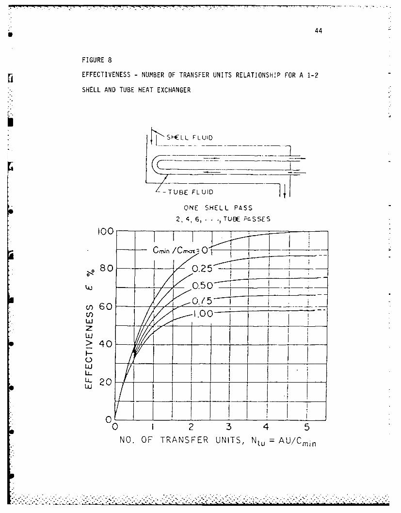
43
exchanger flow arrangement. These parameters are useful in allowing for
compact graphical presentation of exchanger performance. Figure 8
graphically shows the relationship between these parameters for a heat
exchanger with one shell pass and 2-, 4-, 6-, or 8-tube passes. The
algebraic relationship between the number of transfer units, the capa-
city rate ratio and the heat exchanger effectiveness is:[39]
2-- 1 - C - (I+C2)I/2E
NTU = -( +C2)- /2 In E
2- - 1 + C + (I+C2 )1/2
E
CMINwhere C =
CMAX
Although this equation was derived for a heat exchanger with one
shell pass and two tube passes, it is used as the basic NTU-Relationship.
The equations that result from the study of 4-, 6-, or 8-pass exchangers
yield results that are numerically so close to the two-tube-pass
situation that nothing is to be gained by the utilization of these more ..
complex equations.[40]
M. Calculation of Estimated Overall U-Value
Tables of U-values typical of various applications of shell and tube
exchangers are widespread. They normally are tabulated giving a range
of U-values that can be expected for two particular fluid streams. For
example, a water-to-water shell and tube heat exchanger will have a U-
value of between 250 - 300 BTU/hr-ft 2 -OF. This is in contrast to a
water-to-heavy organic liquid shell and tube heat exchanger which would
42
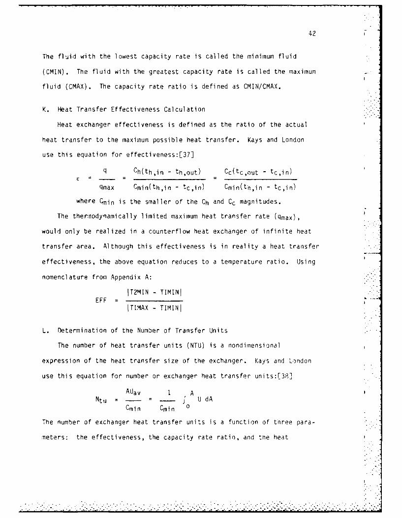
The fluid with the lowest capacity rate is called the minimum fluid
(CMIN). The fluid with the greatest capacity rate is called the maximum
fluid (CMAX). The capacity rate ratio is defined as CMIN/CMAX.
K. Heat Transfer Effectiveness Calculation
Heat exchanger effectiveness is defined as the ratio of the actual
heat transfer to the maximum possible heat transfer. Kays and London
use this equation for effectiveness:[37]
q Ch(th,in - th,out) Cc(tc,out - tc,in)
qmax Cmin(th,in - tc,in) Cmin(th,in - tc,in)
where Cmin is the smaller of the Ch and Cc magnitudes.
The thermodynamically limited maximum heat transfer rate (qmax),
would only be realized in a counterflow heat exchanger of infinite heat
transfer area. Although this effectiveness is in reality a heat transfer
effectiveness, the above equation reduces to a temperature ratio. Using
nomenclature from Appendix A:
IT2MIN - TIMINIEFF =
ITIMAX - TIMINI
L. Determination of the Number of Transfer Units
The number of heat transfer units (NTU) is a nondimensional
expression of the heat transfer size of the exchanger. Kays and London
use this equation for number or exchanger heat transfer units:[38]
AUav 1 ANtu = - f U dA
Cmin Cmin 0
The number of exchanger heat transfer units is a function of three para-
meters: the effectiveness, the capacity rate ratio, and the heat
........................ • . ...... ........ . .

41 -
In Case 2:
Q x 7.4805TS2 TS1 -
MS x DENS x CPS x 60.0
Of course, the fluid properties used in the previous two equations were
only assumed average values. Once the initial value for the shell exit
temperature is obtained, the mean fluid temperature is calculated by:
TS1 + TS2TSAVE =
2
Using this value for the mean shell-fluid temperature, the fluid pro-
perty subroutines are called, the corrected values of density and speci-
fic heat are obtained. A new value for the shell-fluid exit temperature
is calculated using the aforementioned equations, and the new value for
the shell-fluid exit temperature is compared to the previously calculated
value. If they differ by more than one degree of temperature the
iterative process is continued. If the two values for the shell-fluid
exit temperature do not differ by more than a single degree, the last
calculated value for the exit temperature is recognized as the real
shell-fluid exit temperature for use in any future calculations.
J. Calculation of Maximum and Minimum Capacity Rates
The mass flow rate x the specific heat of a fluid is defined as the
capacity rate of that fluid.[36] Equations to calculate the capacity
rates of the shell and tube fluid are:
MS x DENS x CPS x 60.0CS - _
7.4805
MT x DENT x CPT x 60.0CT 7.4805
...1.. . 1-. .> >. >. . ....". . . . . . .. ...- .• -•.-I - 1> ' ' .••, 1. - 1- • ,

40
I. Shell-Fluid Exit Temperature Determination
Since the exit temperature shell-fluid is an unknown, it can be
found by doing an energy balance on the heat exchanger. Two possible
conditions could exist. In Case 1, the tube fluid is being heated. Here . -
the energy gained by the tube fluid must be lost by the shell-fluid. In
Case 2, the tube-fluid is being cooled. Here the energy lost by the
tube-fluid must be gained by the shell-fluid. The heat transfer rate of
the tube-fluid is dependent upon these factors: the tube-fluid flow
rate, the tube-fluid density, the tube-fluid specific heat, and the
magnitude of the tube-fluid exit and entrance temperature difference.
In Case 1:
MT x DENT x CPT x 60.0Q x (TT2 - TTI)
7.4805
In Case 2:
MT x DENT x CPT x 60.0Q x (TT1 - TT2)
7.4805
Note that 60.0 is a conversion factor for minutes per hour and 7.4805 is
a conversion factor for gallons per cubic feet.
Since an average shell-fluid temperature cannot be determined until
the exit temperature of the shell-fluid is known, average values for the
fluid properties are assumed depending upon the shell-fluid choice.
An iterative procedure will be followed in order to obtain the
correct value of the shell exit temperature. The equations are:
In Case 1:
Q x 7.4805TS2 TS1 -
MS x DENS x CPS x 60.0

39
H. Thermo-Hydraulic Properties of the Tube Fluid
Four basic properties of each fluid must be known to design a
liquid-to-liquid heat exchanger. These are: density, viscosity, speci-
fic heat and thermal conductivity. The temperature at which the fluid
properties are determined is the mean fluid temperature, which is simply
the arithmetic average of the entrance and exit temperatures. The mean
tube fluid temperature is:
(TTI + TT2)TTAVE =
2
This computer program calculates these four fluid properties by way
of calling separate subroutines. Each of the seven fluid choices has
four subroutines which are associated with it, one for each of the fluid
properties. For example, water has these subroutines:
Subroutine Desired Fluid Property
OWATER Density
CPWATR Specific Heat
VWATER Dynamic Viscosity
KWATER Thermal Conductivity
Each subroutine contains temperature dependent data of its par-
ticular fluid property. An interpolation algorithm is employed to
calculate the desires fluid temperature if the mean fluid temperature
does not match the temperature data points filed for that particular
fluid property. A complete listing of all of the fluid property
subroutines for water is found in Appendix C. The other fluid subrouti-
nes are strikingly similar in form to these subroutines.
-!
. . . . . . . . .. . . . . . . . . . . .- * .

38
between the tubes, which depends on the tube pitch and tube size, that
make up the crossflow area.
The tube clearance is simply:
TC = TPH - DTOT
The calculations of the shell-side flow rates can now be inscribed. The
minimum shell-side flow rate for a heat exchanger using a KI baffle
spacing is:
DSIUQSK1L = 3.116875 x (0.2 x DSI) x - x TC x 2 ft/sec
TPH
The maximum shell-side flow rate for the same exchanger is:
OSIUQSKIH = 3.116875 x (0.2 x DSI) x - x TC x 4.5 ft/sec
TPH
The flow rate equations for exchangers which use the other two
baffle spacings are:
For a K2 baffle spacing:OS-.- U
DSIU
QSK2L = 3.116875 x (0.45 x DSI) x - x TC x 2 ft/secTPH
DSIUQSK2H = 3.116875 x (0.45 x DSI) x - x TC x 4.5 ft/sec
TPH
For a K3 baffle spacing:
DSIU
QSK3L = 3.116875 x DSI x - x TC x 2 ft/secTPH
DSIUQSK3H = 3.116875 x DSI x - x TC x 4.5 ft/sec
TPH

37 -
G. Maximum and Minimum Shell-Side Flow Rates
In keeping with generally recommended practice the shell-side velo-
city should be at least 2 ft/sec but not more than 4.5 ft/sec.[33,34]
The shell-side crossflow area is dependent on three factors: the tube
pitch, the diameter of the shell, and the baffle spacing. The only
parameter that has not been discussed previously is the baffle spacing.
The baffle spacing is the distance between baffles within the exchanger.
There is a generally recommended range of baffle spacings. The baffles
should be no closer than a distance equal to one-fifth the shell
diameter and should not be spaced farther apart than a distance equal to
the shell diameter.[35] In keeping with this practice, three shell
baffle spacings are considered in the calculations. They are the two
extreme baffle spacing conditions and one midway between these two
extremes. Numerically the baffle spacings are defined:
Baffle Spacing Calculation
KI DSI x 0.2
K2 DSI x 0.45
K3 DSI x 1.00
The estimation of the shell-side cross flow area follows a calcula-
tion procedure that is based upon the previously cited work of Kern.
If the shell inside diameter is divided by the tube pitch, a ficti-
tious number of tubes which may be assumed to exist in the center of the
shell is obtained. In actuality, there is more than likely no central
row of tubes but rather a row of tubes on either side of the center with
less tubes than is calculated by this procedure. This departure from
reality is neglected. For each tube there is considered to be a clearance

36
3.116875 x NT8 x ATIN x 8.0 ft/secQTH8
8.0 passes
These two equations incorporate the assumption that there is an equal
amount of tubes in each of the eight tube passes. This is consistent
with actual shell and tube exchanger manufacture.[32]
The calculations for the remainder of the construction con-
figurations are quite similar. For 6-pass construction:
3.116875 x NT6 x ATIN x 2.0 ft/secQTL6 =
6.0 passes
3.16875 x NT6 x ATIN x 8.0 ft/secQTH6
6.0 passes
For 4-pass construction:
3.116875 x NT4 x ATIN x 2.0 ft/secQTL4 "
4.0 passes
3.116875 x NT4 x ATIN x 3.0 ft/secQTH4
4.0 passes
For 2-pass construction:
3.116875 x NT2 x ATIN x 2.0 ft/secQIL2
2.0 passes
3.116875 x NT2 x ATIN x 8.0 ft/secQTH2
2.0 passes
1.1 . ,i-. ;.:1..~~ ~ ~~ ~~ ~~ ~ . ..1 1- .- .-. - . ... . . .-' -.- -- . , -i - .- 1 : .. - . - ,
35
NT6 = ARAV x F1 x F6
NT8 = ARAV x F1 x F8I
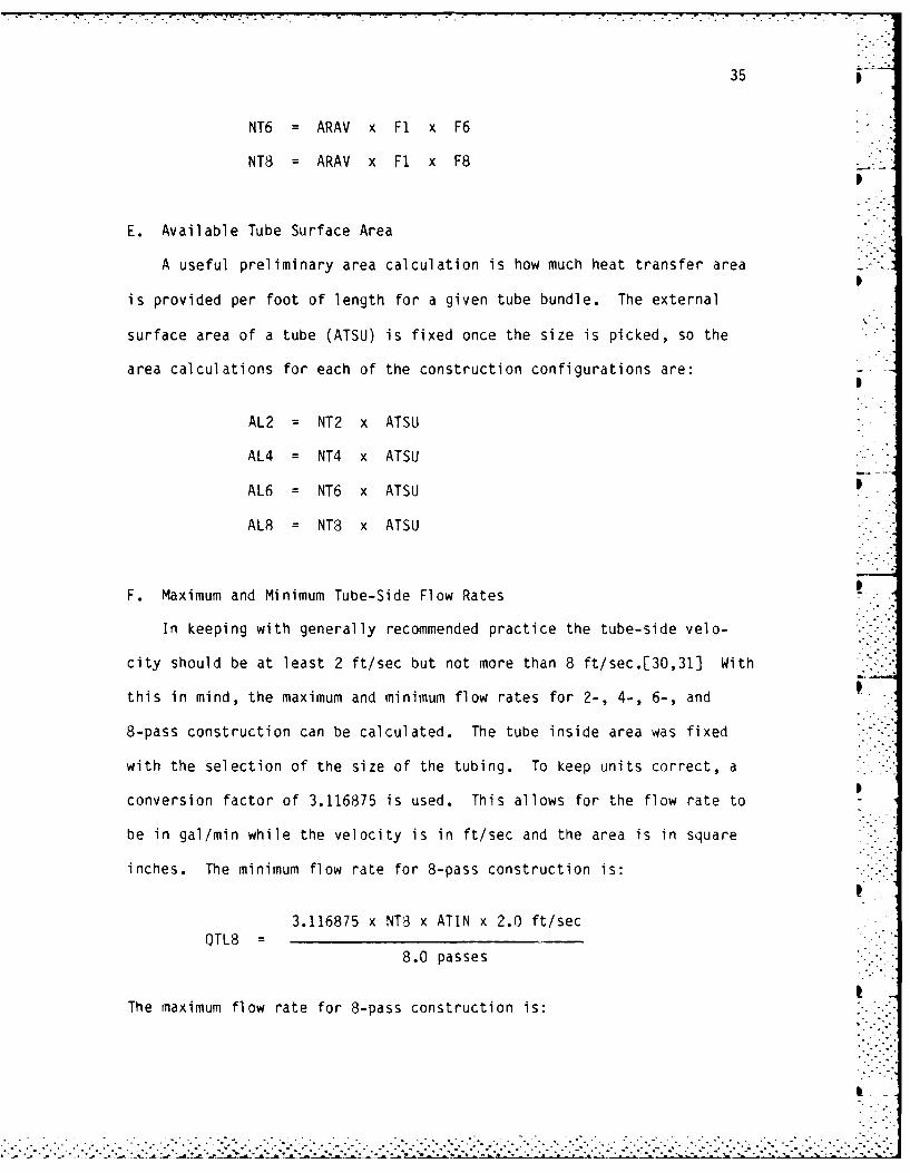
E. Available Tube Surface Area
A useful preliminary area calculation is how much heat transfer area -.
p
is provided per foot of length for a given tube bundle. The external
surface area of a tube (ATSU) is fixed once the size is picked, so the
area calculations for each of the construction configurations are:
AL2 = NT2 x ATSU
AL4 = NT4 x ATSU
AL6 = NT6 x ATSU 5...
AL8 = NT8 x ATSU
F. Maximum and Minimum Tube-Side Flow Rates
In keeping with generally recommended practice the tube-side velo-
city should be at least 2 ft/sec but not more than 8 ft/sec.[30,31] With
this in mind, the maximum and minimum flow rates for 2-, 4-, 6-, and
8-pass construction can be calculated. The tube inside area was fixed
with the selection of the size of the tubing. To keep units correct, aI
conversion factor of 3.116875 is used. This allows for the flow rate to
be in gal/min while the velocity is in ft/sec and the area is in square -
inches. The minimum flow rate for 8-pass construction is:p
3.116875 x NT8 x ATIN x 2.0 ft/secQTL8 : • _
8.0 passes
The maximum flow rate for 8-pass construction is:
2 .- -
77 7 7 7' W
34
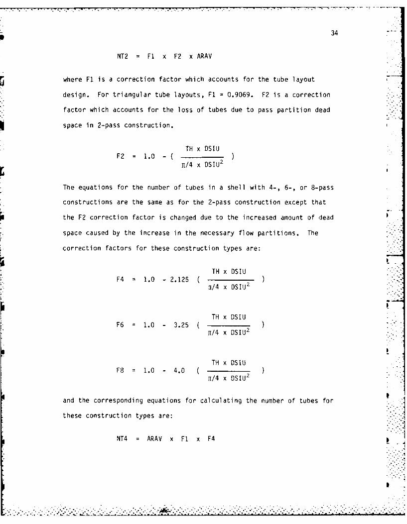
NT2 = F1 x F2 x ARAV
where F1 is a correction factor which accounts for the tube layout
design. For triangular tube layouts, F1 : 0.9069. F2 is a correction
factor which accounts for the loss of tubes due to pass partition dead
space in 2-pass construction.
TH x DSIUF2 = 1.0 - ( )11/4 x DSIU 2
The equations for the number of tubes in a shell with 4-, 6-, or 8-pass
constructions are the same as for the 2-pass construction except that
the F2 correction factor is changed due to the increased amount of dead
space caused by the increase in the necessary flow partitions. The
correction factors for these construction types are:
TH x DSIUF4 = 1.0 - 2.125
1i/4 x DSIIJ 2
TH x DSIUF6 : 1.0 - 3.25
11/4 x DSIU2
I
TH x DSIUF8 = 1.0 - 4.0
11/4 x DSIU2
and the corresponding equations for calculating the number of tubes for .
these construction types are:
NT4 = ARAV x F1 x F4
...................-
33
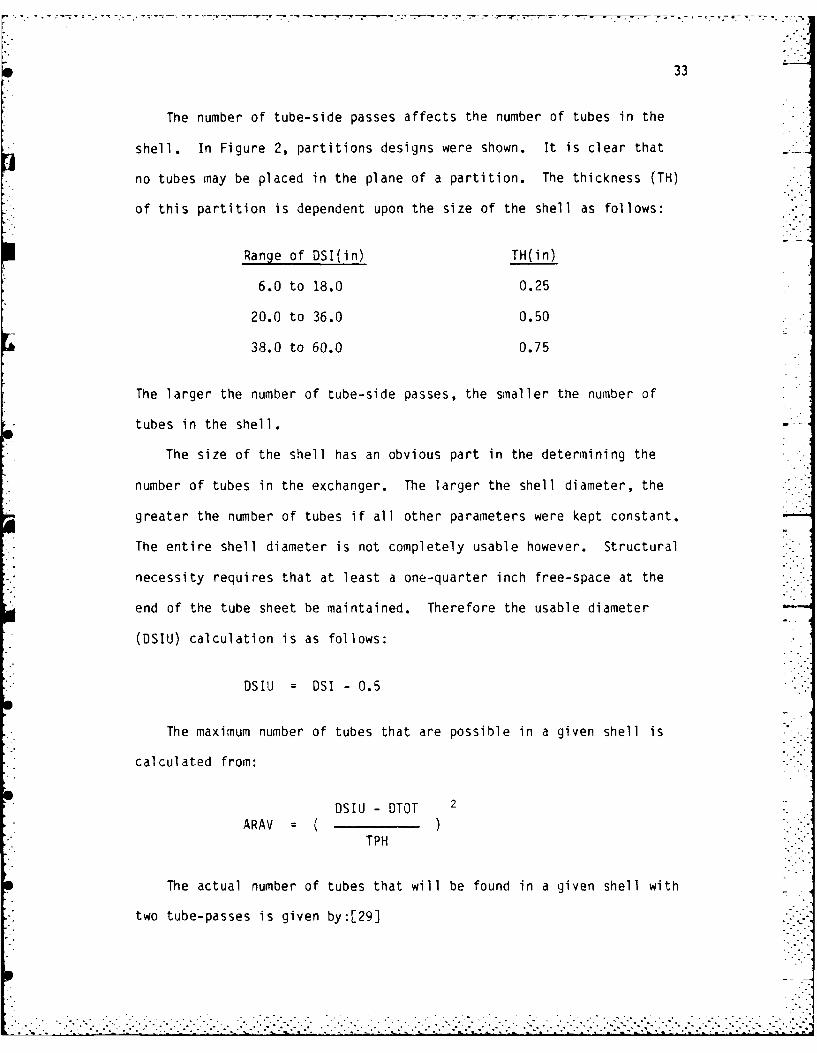
The number of tube-side passes affects the number of tubes in the
shell. In Figure 2, partitions designs were shown. It is clear that
no tubes may be placed in the plane of a partition. The thickness (TH)
of this partition is dependent upon the size of the shell as follows:
Range of DSI(in) TH(in)
6.0 to 18.0 0.25
20.0 to 36.0 0.50
38.0 to 60.0 0.75
The larger the number of tube-side passes, the smaller the number of
tubes in the shell.
The size of the shell has an obvious part in the determining the
number of tubes in the exchanger. The larger the shell diameter, the
greater the number of tubes if all other parameters were kept constant.
The entire shell diameter is not completely usable however. Structural
necessity requires that at least a one-quarter inch free-space at the
end of the tube sheet be maintained. Therefore the usable diameter
(OSIU) calculation is as follows:
DSIU = DSI - 0.5
The maximum number of tubes that are possible in a given shell is
calculated from:
DSIU - DTOT 2ARAV ( )
TPH
The actual number of tubes that will be found in a given shell with
two tube-passes is given by:[29]

32
FIGURE 7
STANDARD TUBE LAYOUT DESIGNS
r.-
TRIANGULAR TUBE LAYOUT
SQUARE TUBE LAYOUT"
ROTATED SQUARE TUBE LAYOUT
........................ .. .. . .. .. . .. .. .
. . . . ., .. 0 . . . . . . . . . . . . .
0000000

31
D. Number of Tubes Calculations
The number of tubes possible in a given shell diameter is dependent
upon five factors: the tube size, the tube layout design, the tube
pitch (TPH), the number of tube-side passes, and the diameter of the
shell (DSI). Each of these parameters will be explained and the final
equation for calculating the number of tubes will be presented.
The tube size fixes the outside diameter of the tubes. All other
parameters equal, it is obvious that more 1.0 inch tubes would fit in a
given shell than would 1.5 inch tubes.
The tube layout design is the pattern or tube construction. Three
patterns have widespread usage today, they are: the triangular pattern,
the square pattern and the oriented square pattern. Each of these pat-
terns are shown in Figure 7. The spacing is clearly different for the
triangular and square patterns. This computer design uses calculations
for triangular tube layouts only.
The holes in the tubesheet cannot be drilled very closely together,
since too thin a separation structurally weakens the tubesheet. The
shortest distance between two adjacent tube holes is the clearance which
has become standard in practice. The tube pitch is the shortest center-
to-center distance between adjacent tubes. This dimension, which
depends on the size of the tubing used, is also standard. For triangular
tube layouts, the following tube pitches have been designated:
OTOT(in) TPH(in)
0.75 15/16 or 0.9375
1.00 1 1/4 or 1.25
1.25 1 9/16 or 1.5625
1.50 1 7/8 or 1.875

30
At this point, all the data that the computer program needs to pro-
Svide a list of shell and tube heat exchanger configurations that will
accomplish the required heat transfer is provided except for any
restrictions that may need to be imposed.
The site that the heat exchanger will eventually occupy may be
fixed, and only a certain space may be available. The length of the
heat exchanger would certainly need to be restricted. Moreover, as the
heat exchanger would most probably need some sort of inspection or main-
tenance done to it during its lifetime, it is common practice to require
that the maximum length of the heat exchanger be less than one-half the
available free-space at the site. This is because maintenance of the
tubes requires the removal of the shell and obviously one would need at
least twice the length of the heat exchanger to accomplish this task.
Therefore, the user is asked to input the maximum allowable length of
the heat exchanger to the program.
Another important limitation that normally is imposed on shell and
tube heat exchanger designers is the amount of pressure drop that is
allowed through the tubes and the shell. Normally, the size of the
pumps and corresponding pumping power is fixed, and therefore a limit on
the maximum head loss through a unit must be kept within known limits.
Even if the pump sizes are not predetermined, reasonable pressure loss
restrictions are imposed since the larger the pressure loss allowed, the
larger the pumping power required. This capital cost outlay must be
considered in the decision for optimum design. The user inputs these
maximum allowable pressure losses as prompted by the program.
. . .
44
FIGURE 8
ri EFFECTIVENESS -NUMBER OF TRANSFER UNITS RELATIONSHIP FOR A 1-2
SHELL AND TUBE HEAT EXCHANGER
1Sf LL FLUID
TUBE FLUID
ONE SHELL PASS
2. 4, 6, *,TUBE Pf.SSES
080- 0. 2 5 -
0,L -- 0 5-7 -1
LL
uJJ
0 1 2 3 4 5NO0. O F TRANSFER UNITS, Nt~u AU./C mi

45
have a U-value of between 40-75 BTU/hr-ft2 -*F. These values are for
unfouled tubes. Average (mid-range) values for all possible com-
binations of the seven fluid choices have been incorporated into the
computer program as a design check of the actual U-value which is calcu-
lated later in the program. The source used for these estimated U-
values is Heat Exchangers by Kakac and Bergles. These values are for
plain (unfinned) tubes.
Tabulated values of fouling resistances are also common. If the
user wants a fouling factor (RFOULT) added to the calculation of the
overall U-value, the following equation is used.
U1
RFOULT +UC
where UC is the U-value for clean (unfouled) tubes. Table 1 lists the
overall U-values and fouling resistances used in the program.[41]
N. Determination of Possible Exchanger Configurations
Once the tube-fluid flow rate, the shell-fluid flow rate, the maxi-
mum tube length, and the maximum allowable tube-side and shell-side
pressure losses have been specified, the computer does a systematic
check of every possible heat exchanger configuration to see if it meets
the problem specifications. It checks each available shell size (from
six to sixty inches), with every possible number of tube-side passes (2,
4, 6, or 8) and every possible baffle spacing (0.2, 0.45, and 1.0), a
total of 336 possible exchanger configurations, to see which, if any,
meet the problem requirements.
- . ". , '- -'.- .-. =" ".- ,'_-.-" - ,'-'........................"...,.............•.,..-....-... .,

46
TABLE 1
TYPICAL OVERALL DESIGN COEFFICIENTS FOR
SHELL AND TUBE HEAT EXCHANGERS
TOTALFOULING OVERALL
RESISTANCE U-VALUEHR-FT 2 -OF BTU
FLUID 1 FLUID 2 BTU HR-FT 2OF
Water Water 0.0015 275.0
Water Light Organic 0.0015 150.0Liquids
Water Medium Organic 0.002 100.0Liquids
Water Heavy Organic 0.0025 57.5Liquids
Light Organic Light Organic 0.002 115.0Liquids Liquids
Light Organic Medium Organic 0.0025 85.0Liquids Liquids
Light Organic Heavy Organic 0.003 50.0Liquids Liquids
Medium Organic Medium Organic 0.003 65.0Liquids Liquids
Medium Organic Heavy Organic 0.0035 35.0Liquids Liquids
Heavy Organic Heavy Organic 0.005 20.0Liquids Liqids
Note: Light Organics include: Methyl Alcohol and Gasoline
Medium Organics include: Dowtherm A and Kerosene
Heavy Organics include: SAE 10 Lubricating Oil and Ethylene Glycol
.~~~~~... .h,-_ - - .- :-1.-: :.-1.1. ,.: ". : :. -:,- ,.:.::" " " " " " " •" " :: :::: :: ::: ::: : :: ] :.- :: :::::: :;i: .i1: : - ". • -" . . .' .. ' ". . .'. .'. .'.. '.. '.. '. . ... ' .-' .. ' ,'.. ',. '.. '... .' .. . '. .

47
The first check that is made is to see whether the tube-fluid flow
rate falls within the maximum and minimum allowable tube-fluid flow
rates for that particular pass configuration. If the tube-fluid flow
rate is acceptable, the shell-fluid flow rate is checked to see if it
falls within the range of maximum and minimum allowable shell-fluid flow
rates for any of the three baffle spacings. Both the tube-fluid and the
shell-fluid must fall within their respective acceptance ranges for
further checks to continue.
If the tube-fluid and shell-fluid flow rates are acceptable a
pressure loss and length check subroutine PRESCK, is called. A listing
of PRESCK is found in Appendix 0.
This subroutine contains the bulk of the thermal-hydraulic design
equations. Each of the major equations and their source will be
explained in detail. _
The velocities of the tube-fluid and the shell-fluid are calculated.
The shell-fluid velocity (VS) is simply the shell-fluid flow rate (MS)
divided by the crossflow area of the shell (ASC). The evaluation of the
shell crossflow area was previously discussed in the determination of
the minimum and maximum shell-side flow rates of the exchanger. The -
shell-fluid velocity reduces to:
MSVS - x C
ASC
where C is a conversion factor (=.3208342) which allows velocity to be
in ft/sec while mass flow rate is input in GPM and the area is in in2.
The tube-side fluid velocity (VT) is simply the tube-fluid flow rate
(MT) divided by the total tube-side area per pass. As noted earlier,
• i . . . • - - .- . . . - .. - .- - -.--. , . . -. . • . - . .. . . - - .- , . .. . .-. -.- ..- .. .

48
the number of tubes that will be found in a given heat exchanger will
decrease as the number of tube-passes increases. The tube-side velocity
equation will therefore differ for each pass-construction type. This is
because the tube-side area is equal to the number of tubes multiplied by
the internal area of the tubes (ATIN). The tube-side velocity equation
is for 2-pass construction is:
Cx MTVT -
NT2ATIN x
2.0
where C is the same conversion factor that was used in the calculation
of the shell-side velocity. The equations for 4-, 6-, or 8-pass
construction are the same with the exception of the substitution of the
appropriate number of tubes per pass for that particular pass
construction.
The mass velocity of the shell-fluid (GS), and the mass velocity of
the tube-fluid (GT) can now be found by multiplying the velocities by
the density of the particular fluid.
GS VS x DENS
GT : VT x DENT
The next step is to calculate the dimensionless Reynolds Number.
The calculation of the tube-side Reynolds Number (RET) is straightfor-
ward. This is simply the tube-side mass velocity multiplied by the tube
inside diameter (DTIN) divided by the tube-fluid dynamic viscosity
(DVT).
=' € .-- .- . ".. . . . . . ."
-. . . . . . ...-' ". . .. . . ' °" . ; " " "' " . .
49
DTINx GT
12.0RET
DVT
The tube inside diameter of the tube, which is in inches, is divided by
the conversion factor 12.0 to get it into proper units of feet.
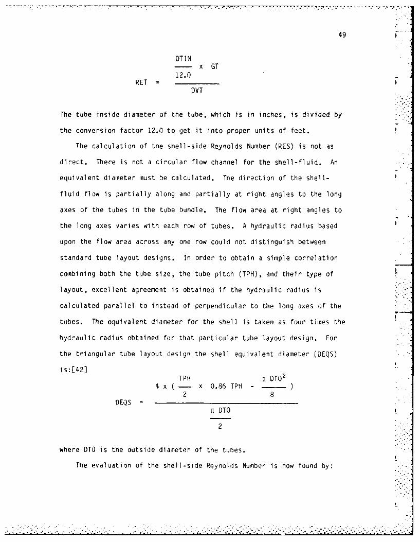
The calculation of the shell-side Reynolds Number (RES) is not as
direct. There is not a circular flow channel for the shell-fluid. An
equivalent diameter must be calculated. The direction of the shell-
fluid flow is partially along and partially at right angles to the long
axes of the tubes in the tube bundle. The flow area at right angles to
the long axes varies with each row of tubes. A hydraulic radius based
upon the flow area across any one row could not distinguish between
standard tube layout designs. In order to obtain a simple correlation
combining both the tube size, the tube pitch (TPH), and their type of L
layout, excellent agreement is obtained if the hydraulic radius is
calculated parallel to instead of perpendicular to the long axes of the
tubes. The equivalent diameter for the shell is taken as four times the
hydraulic radius obtained for that particular tube layout design. For
the triangular tube layout design the shell equivalent diameter (DEQS)
is:[42]TPH n DTO 2
4 x (- x 0.86 TPH -
2 8DEQS
ri DTO
2
where DTO is the outside diameter of the tubes.
The evaluation of the shell-side Reynolds Number is now found by:
.. . ... .•.". . ...............................
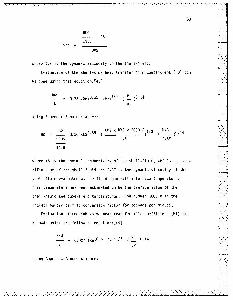
50
DEQGS
12.0RES =
DVS
where DVS is the dynamic viscosity of the shell-fluid.
Evaluation of the shell-side heat transfer film coefficient (HO) can
be done using this equation:[43]
h 0.36 (Re)0 °55 (Pr)1/3 ( 01
k pf
using Appendix A nomenclature:
KS CPS x DVS x 3600.0 1/3 DVSHO 0.36 RES 0 55 ( ) ( )0.14
DEQS KS DVSF
12.0
where KS is the thermal conductivity of the shell-fluid, CPS is the spe-
cific heat of the shell-fluid and DVSF is the dynamic viscosity of the
shell-fluid evaluated at the fluid-tube wall interface temperature.
This temperature has been estimated to be the average value of the
shell-fluid and tube-fluid temperatures. The number 3600.0 in the
Prandtl Number term is conversion factor for seconds per minute.
Evaluation of the tube-side heat transfer film coefficient (HI) can
be made using the following equation:[441
hid ... .0.027 (Re)0 "8 (Pr) 1/3 ( )0.14
k
using Appendix A nomenclature:
....--.-...---..... ,.... ......... .......................... '. "-"".""-..i..........-."..... ~ i- L~..... - •-: "--.....-......".. ""-".....................................

51 -
KT CPT x DVT x 3600.0 3 DVT 0.14HI - 0.027 RET 0 8 ( )1/3 )
DTIN KT DVTF
12.0
where KT is the thermal conductivity of the tube-fluid, CPT is the spe-
cific heat of the tube-fluid and DVTF is the dynamic viscosity of the
tube-fluid evaluated at the fluid-tube wall interface temperature.
The tube wall resistance (RW) is evaluated. Although this
resistance can be neglected for many metals, it is evaluated for all
since the more exotic metals such as zirconium and titanium have large
resistances to heat transfer compared to copper and aluminum. TEMA
standards handbook provides this equation for tube wall resistance
calculations:[45]
d dRW : - x r Ln ( - )
24K d-2t
using Appendix A nomenclature:
DTOT TOTRW = Ln[ 1
24 KW DTOT - 21DTOT - OTIN)
where KW is the thermal conductivity of the tube metal which was fixed
once the choice of the tube metals was made in the program.
All the parameters needed for the determination of the overall heat
transfer coefficient (UCALC) have now been determined. Usiig another
equation from the TEMA standards handbook the U-value is calculated
by:[46]
I Ao 1 Ao- + ro + rw . ri ( ) + ( - )ho Ai hi Ai
. -. ,i.'::..-- "i-.'.- .. .........-... .. .. ... . ,. i .' -'i " 1 . 1 L. . 1

52
where ro is the fouling resistance on the outside of the tubes, ri isAo
the fouling resistance on the inside of the tubes and ( - ) is the ratioAi
of the outside to inside surface of the tubing. The calculation of the
U-value differs depending upon the user's desire to add fouling factors.
If the user wants fouling factors added the equation is:
UCALC1 1
-- + RO + RW + (RI x TRATIO) + ( -x TRATIO)HO HI
where TRATIO is the area ratio described above. RO and RI are the
fouling resistances on the outside and inside of the tube respectively.
They have been computed depending upon the tube-fluid and shell-fluid
choices. The total of the RI and RO is equal to the total fouling
resistances found in Table 1.
If the user wants the U-value calculated for clean tubes the
equation simplifies to:
UCALC =1 1-- + RW + ( -x TRATIO )HO HI
The required heat transfer area (ACORR) can now be calculated by:
NTU x CMINACORR =
UCALC
Using this valje of the heat transfer area, the required length of
tubing (L) can be calculated depending upon the pass construction. For
2-pass construction:
.................................................................
• ' i .. .. 5 ..i . " l l i - .... " " ....i ,- ' '..- - '- ' - . . --- .. --. ... . .i -. i ...' -. . ..2 2 - 2 .i i i .i 2

53
ACORRL
AL2
I
where AL2 is the tube bundle surface are per foot of tube length for
2-pass construction. The length calculation for 4-, 6-, or 8-pass
construction is similar to this equation.
This calculated length must be less than the length restriction
imposed by the user. This is the first of three checks that are done in
the subroutine PRESCK. All three must be successfully achieved before
the exchanger configuration is printed as a possible solution to the heat
exchanger problem.
Checks 2 and 3 deal with the maximum allowable pressure losses in
the exchanger.
The tube-side pressure loss is calculated using two equations from
Kern. The first equation accounts for the pressure drop in tubes.
This equation is:[47]
f Gt2 L mA Pt : ._ ___,__
)0.14 :2g pD ( -)
Pw
In Appendix A terminology:
FRT GT2 NP L .006944PLTF
DTIN DVT- ) 2 AG ( - )0.14 DENT
12.0 DVTF
where NP is the number of the tube passes, .006944 is a conversation
factor for pounds per square inch, AG is a gravitational acceleration
constant and FRT is a tube-side friction factor. This friction factor
d m ~ . , • . .- -. , -.- - .. . .- - ... . . . " . " . - . . o -

54
is calculated by a subroutine called TFRICT. A listing of this
subroutine can be found in Appendix E. This subroutine contains data on
friction factors correlated by Sieder and Tate for fluids which are
being heated or cooled in tubes. The subroutine uses a linear inter- -".
polation algorithm to calculate the friction factor depending on the
Reynolds Number of the tube-side fluid. The Sieder and Tate correlated
data was accepted and published by TEMA for use in pressure loss
calculations.
Since the fluid must flow from one pass into the next pass by doing
a 1300 direction change in the tube channel area of the exchanger, an
additional pressure drop is experienced. This loss is referred to as
the return loss. Kern proposed this equation to account for this
pressure drop:[481
4.0 n V2
APr =S 2g
in Appendix-A nomenclature:
4.0 NP VT2
PLTR - .4335DENT(-)2 AGDENW
where .4335 is a conversion factor from feet of water to pounds perDENT
square inch and the ratio ( - ) is the specific gravity of the fluid.DENW
Manufacturers of heat exchangers use a modification of this return loss
equation. The factor of 4.0 was determined to provide results that were
much too conservative. Practice is to use a factor of 2.0 in
calculations.r49] The equation used in PRESCK does in fact use tnis
factor of 2.0.

- - r. . .. , .w m . - . ... •. > . .. --.. ..-
55
The total tube-side pressure drop is therefore:
PLTOT = PLTF + PLTR
This total tube-side pressure loss is compared to the maximum allowable
tube-side pressure loss imposed by the user. If the tube-side pressure
loss is greater than the allowable loss, the exchanger configuration is
not deemed acceptable.
The last check is associated with the shell-side pressure loss. The
pressure drop in a shell and tube heat exchanger is proportional to the
number of times the fluid crosses the tube bundle between tube sheets.
It is also proportional to the distance the fluid flows across the tube
bundle. The calculation of the pressure loss can be made from:[50]
f G2 Ds (N+I)APs
2 gp e )0.14PW
where N is the number of baffles in the heat exchanger, De is the
equivalent diameter of the shell cross flow channel, and f is the shell-
side friction factor. This friction factor is calculated by a
subroutine called SFRICT. A listing of this subroutine is in Appendix
F. Subroutine SFRICT contains data on shell-side friction factors for
bundles with 25% cut segmental baffles.[51] Like TFRICT, this subroutine
uses a linear interpolation algorithm to calculate the fluid friction
factor depending on the Reynolds Number of the shell-side fluid.
The shell-side pressure loss equation using nomenclature from
Appendix A takes the form:
- - - - - - -.-- -.

56
L x 12.0
FRS L GS2 ( + ) .006944DSI x PICKS
PLSTOT =DVS 014
2 AG DENS DEQS (-)DVFS
where PICKS is the choice of baffle spacing, FRS is the shell-side fluid
friction factor calculated in subroutine SFRICT, and .006944 is a con-
version factor from pounds per square feet to pounds per square inch.
This total shell-side pressure loss is compared to the maximum allowable
shell-side pressure loss imposed by the user. If the calculated loss is
less than the maximum allowable pressure loss the heat exchanger con-
figuration is regarded as acceptable.
Finally, if the exchanger configuration successfully meets the
length restriction, the tjbe-side pressure loss restriction and the
shell-side pressure loss restriction it is considered as an acceptable
exchanger configuration that will meet the limitations of the problem
input by the user.
0. Output of Possible Exchanger Configurations
All heat exchanger configurations whiLh meet the required heat duty
of the problem and are within the length and pressure drop restrictions
are output to the user. The output is performed by calling four
subroutines, PRINT2, PRINT4, PRINT6, and PRINT3. Each of these sub-
routines correspond to their particular pass-construction type. A
listing of these subroutines are in Appendix G.
If no exchanger configuration of a particular pass-construction
meets the problem specifications, a verbal output to that effect is
printed.
• -.. -
57
If no exchanger configuration of any pass-construction category
meets the problen specifications, a message is printed which states that
the length and pressure restriction cannot be met and the user must. use
split shell design or multiple shells in series. This computer program
is not capable of handling those types of design.
P. User Selection of Possible Exchanger Configurations
Once the program has listed all the possible heat exchanger con-
figurations by pass-construction, the user is asked to make a selection
of a heat exchanger configuration. The user is reminded that only the
listed configurations will meet the problem specifications.
Tne user responds to three input requests which pertain to his
choice of exchanger configurations. The need only respond to the
questions posed by the program. The first input is the shell diameter.
The second input is the number of tube-side passes. The final input is
the baffle spacing. Once the user specifies the choice of heat
exchanger configurations, the program calculates the final output data.
9. Calculation of Estimated Capital Cost
Many factors enter into how much a shell and tube heat exchanger :nay
cost. The cost of engineering and design, raw materials, and labor are
only three of the many parameters that must be explored. Each shell nd
tube heat exchanger manufacturer has its own method for doing cost
calculations for j specific exchanger design.
One would assume tnat the length of a heat exchanger, as well as the
shell diameter would affect the cost. Sice material cost; play an
iportant role, the number of tubes would also seen to have an effect on
...... .. . ..

71
THE AVAILABLE HEAT EXCHANGERCONFIGURATIONS ARE AS FOLLOWS:
THE AVAILABLE 2-PASS HEAT EXCHANGERCONFIGURATIONS ARE AS FOLLOWS:
SHELL DIAMETER 14.OOOC INCHES:WITH A 1.000000 BAFFLE SPACINGSHELL DIAMETER 18.00000 INCHES:WITH A 0.4500000 BAFFLE SPACINGSHELL DIAMETER 20.00000 INCHES:WITH A 0.4500000 BAFFLE SPACING
THE AVAILABLE 4-PASS HEAT EXCHANGERCONFIGURATIONS ARE AS FOLLOWS:
SHELL DIAMETER 18.00000 INCHES:WITH A 0.4500000 BAFFLE SPACINGSHELL DIAMETER 20.00000 INCHES:WITH A 0.4500000 BAFFLE SPACINGSHELL DIAMETER 22.00000 INCHES:WITH A 0.4500000 BAFFLE SPACINGSHELL DIAMETER 24.00000 INCHES:WITH A 0.2000000 BAFFLE SPACINGSHELL DIAMETER 26.00000 INCHES:WITH A 0.2000000 BAFFLE SPACINGSHELL DIAMETER 28.00000 INCHES:WITH A 0.2000000 BAFFLE SPACING
THE AVAILABLE 6-PASS HEAT EXCHANGERCONFIGURATIONS ARE AS FOLLOWS:
SHELL DIAMETER 22.00000 INCHES:WITH A 0.4500000 BAFFLE SPACINGSHELL DIAMETER 24.00000 INCHES:WITH A 0.2000000 BAFFLE SPACINGSHELL DIAMETER 26.00000 INCHES:WITH A 0.2000000 BAFFLE SPACINGSHELL DIAMETER 28.00000 INCHES:WITH A 0.2000000 BAFFLE SPACINGSHELL DIAMETER 30.00000 INCHES:WITH A 0.2000000 BAFFLE SPACINGSHELL DIAMETER 32.00000 INCHES:WITH A 0.2000000 BAFFLE SPACINGSHELL DIAMETER 34.00000 INCHES:WITH A 0.2000000 BAFFLE SPACING
THE AVAILABLE 8-PASS HEAT EXCHANGERCONFIGURATIONS ARE AS FOLLOWS:

70
I
0.0 CHROME MOLY STEEL (2.25%)10.0 CHROME MOLY STEEL (5%)11.0 CHROME HOLY STEEL (12%)
12.0 STAINLESS STEEL (18%)13.0 STAINLESS STEEL (25%)14.0 ADMIRALTY METAL15.0 COPPER16.0 NICKEL17.0 ZIRCONIUM18.0 TITANIUM
PLEASE ENTER THE CHOICE NUMBER OF THE TYPE OFMATERIAL DESIRED.(ie 1.0 6.0 18.0 etc.)
6.0
DO YOU WANT TO CHANGE THE TUBE FLUID CHOICE ?
N
DO YOU WANT TO CHANGE THE SHELL FLUID CHOICE ?
N
00 YOU WANT TO CHANGE THE TUBE FLUID TEMPS ?
N
DO YOU WANT TO CHANGE THE TUBE FLUID FLOW RATE ?
N
DO YOU WANT TO CHANGE THE SHELL FLUID TEMP ?
N
DO YOU WANT TO CHANGE THE SHELL FLUID FLOW RATE ?.
N
DO YOU WANT TO CHANGE THE DECISION ON WHETHER ORNOT A FOULING FACTOR IS USED '?
N
DO YOU WANT TO CHANGE THE LENGTH RESTRICTION ?
N
DO YOU WANT TO CHANGE THE MAXIMUM ALLOWABLEPRESSURE LOSSES 9
N
. . ~. . . . . . . . . . . . . . . .

69
NUMBER OF TUBE-SIDE PASSES: 8.0
BAFFLE SPACING: 0.20 OR
6.80 INCHES
EXCHANGER TUBE LENGTH: 1.461 FEET
TUBE-SIDE PRESSURE LOSS: 1.34 POUNDS PER SQUARE INCH
SHELL-SIDE PRESSURE LOSS: 0.18 POUNDS PER SQUARE INCH
ESTIMATED CAPITAL COST: $ 418562.90
U = 194.6903UCALC = 243.1180
00 YOU WANT TO TRY A DIFFERENT HEAT EXCHANGERCONFIGURATION ? TYPE Y FOR YES AND N FOR NO.
N
***** SINCE COPPER TUBING IS RELATIVELY EXPENSIVE, THE***** TUBING MATERIAL WILL BE CHANGED TO REGULAR CARBON STEEL***** TO SEE THE EFFECT ON THE FINAL RESULTS. ALL OTHER***** PARAMETERS WILL BE LEFT UNCHANGED FROM THE ORIGINAL***** PROBLEM STATEMENT.
DO YOU WANT TO CHANGE ANY OF THE INPUT PARAMETERSTO THIS PROBLEM ? TYPE Y FOR YES AND N FOR NO
Y
DO YOU WANT TO CHANGE THE TUBING SIZE ?
N
DO YOU WANT TO CHANGE THE TUBING MATERIAL ?
YWHAT MATERIAL SPECIFICATIONS O0 YOU WANT FORTHE TUBING '
CHOICE NUMBER MATERIAL TYPE
1.0 ALUMINUM TYPE 11002.0 ALUMINUM TYPE 30033.0 ALUMINUM TYPE 30044.0 ALUMINUM TYPE 60615.0 ALUMINUM TYPE 60636.0 CARBON STEEL7.0 CARBON MOLV STEEL8.0 CHROME MOLY STEEL '1%)

68
2.0, 4.0, 6.0, OR 8.0
2.0
WHAT SHELL BAFFLE SPACING DO YOU CHOOSE ? TYPE0.2, 0.45, OR 1.0
1.0
THE FINAL CONFIGURATION IS
SHELL DIAMETER: 14.0 INCHES
NUMBER OF TUBE-SIDE PASSES: 2.0
BAFFLE SPACING: 1.00 OR
14.00 INCHES
EXCHANGER TUBE LENGTH: 8.205 FEET
TUBE-SIDE PRESSURE LOSS: 1.59 POUNDS PER SQUARE INCH
SHELL-SIDE PRESSURE LOSS: 3.54 POUNDS PER SQUARE INCH
ESTIMATED CAPITAL COST: $ 46197.14
U = 194.6903UCALC = 271.4765
DO YOU WANT TO TRY A DIFFERENT HEAT EXCHANGERCONFIGURATION ? TYPE Y FOR YES AND N FOR NO.
YWHAT SHELL DIAMETER DO YOU CHOOSE ? TYPE 12.0,14.0, 28.0 etc.
**~** THE LARGEST CONFIGURATION WILL BE EXAMINED HERE.
34.0
WHAT NUMBER OF TUBE PASSES DO YOU CHOOSE ' TYPE2.0, 4.0, 6.0, OR 8.0
8.0
WHAT SHELL BAFFLE SPACING DO YOU CHOOSE ? TYPE0.2, 0.45, OR 1.0
0.2
THE FINAL CONFIGURATION IS
SHELL DIAMETER: 34.0 INCHES
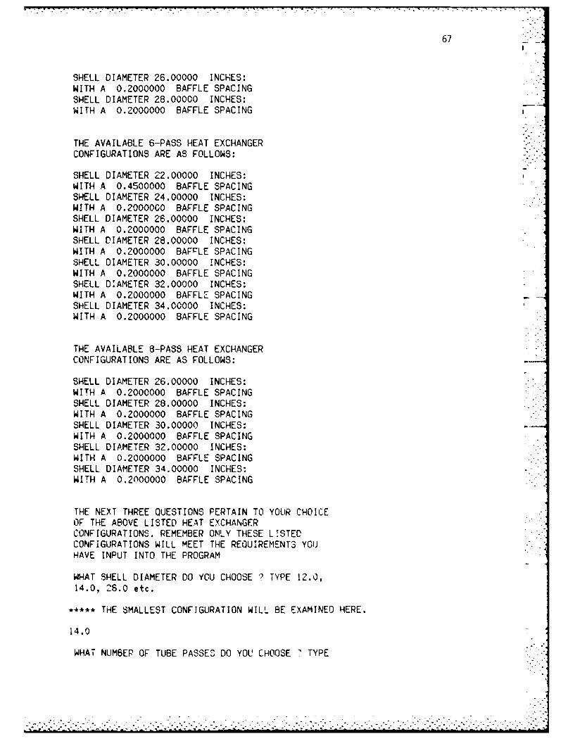
67
SHELL DIAMETER 26.00000 INCHES:WITH A 0.2000000 BAFFLE SPACINGSHELL DIAMETER 28.00000 INCHES:WITH A 0.2000000 BAFFLE SPACING
THE AVAILABLE 6-PASS HEAT EXCHANGERCONFIGURATIONS ARE AS FOLLOWS:
SHELL DIAMETER 22.00000 INCHES:WITH A 0.4500000 BAFFLE SPACINGSHELL DIAMETER 24.00000 INCHES:WITH A 0.2000000 BAFFLE SPACINGSHELL DIAMETER 26.00000 INCHES:WITH A 0.2000000 BAFFLE SPACINGSHELL DIAMETER 28.00000 INCHES:WITH A 0.2000000 BAFrLE SPACINGSHELL DIAMETER 30.00000 INCHES:WITH A 0.2000000 BAFFLE SPACINGSHELL DIAMETER 32.00000 INCHES:WITH A 0.2000000 BAFFLE SPACINGSHELL DIAMETER 34.00000 INCHES:WITH A 0.2000000 BAFFLE SPACING
THE AVAILABLE 8-PASS HEAT EXCHANGERCONFIGURATIONS ARE AS FOLLOWS:
SHELL DIAMETER 26.00000 INCHES:WITH A 0.2000000 BAFFLE SPACINGSHELL DIAMETER 28.00000 INCHES:WITH A 0.2000000 BAFFLE SPACINGSHELL DIAMETER 30.00000 INCHES:WITH A 0.2000000 BAFFLE SPACINGSHELL DIAMETER 32.00000 INCHES:WITH A 0.2000000 BAFFLE SPACINGSHELL DIAMETER 34.00000 INCHES:WITH A 0.2000000 BAFFLE SPACING
THE NEXT THREE QUESTIONS PERTAIN TO YOUR CHOICEOF THE ABOVE LISTED HEAT EXCHANGERCONFIGURATIONS. REMEMBER ONLY THESE LISTEDCONFIGURATIONS WILL MEET THE REQUIREMENTS YOUHAVE INPUT INTO THE PROGRAM
WHAT SHELL DIAMETER DO YOU CHOOSE ? TYPE 12.0,14.0, 26.0 etc.
***** THE SMALLEST CONFIGURATION WILL BE EXAMINED HERE.
14.0
WHAT NUMBEP OF TUBE PASSES DO YOU CHOOSE 7 TYPE
. . - o

66
TRANSFER COEFFICIENT GIVEN FOR CLEAN TUBES ?ANSWER Y FOR YES AND N FOR NO.
y
WHAT IS THE MAXIMUM LENGTH THAT THE HEATEXCHANGER TUBES CAN BE FOR THIS APPLICATION ?REMEMBER, THE SHELL WILL HAVE TO BE REMOVED FORCLEANING SO THE MAXIMUM LENGTH OF THE HEATEXCHANGER TUBES SHOULD BE LESS THAN ONE HALF THELENGTH OF THE ROOM THAT THE HEAT EXCHANGER WILLBE OPERATING IN. TYPE IN THE MAXIMUM LENGTH INFEET THAT THE HEAT EXCHANGER TUBES CAN BE.( ie 5.0 , 7.5, 19.6 etc.)
10.0
WHAT IS THE MAXIMUM ALLOWABLE PRESSURE LOSS INTHE TUBES IN POUNDS PER SQUARE INCH ? (ie 7.4 etc)
5.0
WHAT IS THE MAXIMUM ALLOWABLE PRESSURE LOSS INTHE SHELL IN POUNDS PER SQUARE INCH ? (ie 7.4 etc)
5.0
THE AVAILABLE HEAT EXCHANGERCONFIGURATIONS ARE AS FOLLOWS:
THE AVAILABLE 2-PASS HEAT EXCHANGERCONFIGURATIONS ARE AS FOLLOWS:
SHELL DIAMETER 14.00000 INCHES:WITH A 1.000000 BAFFLE SPACINGSHELL DIAMETER 18.00000 INCHES:WITH A 0.4500000 BAFFLE SPACINGSHELL DIAMETER 20.00000 INCHES:WITH A 0.4500000 BAFFLE SPACING
THE AVAILABLE 4-PASS HEAT EXCHANGERCONFIGURATIONS ARE AS FOLLOWS:
SHELL DIAMETER 18.00000 INCHES:WITH A 0.4500000 BAFFLE SPACINGSHELL DIAMETER 20.00000 INCHES:WITH A 0.4500000 BAFFLE SPACINGSHELL DIAMETER 22.00000 INCHES:WITH A 0.4500000 BAFFLE SPACINGSHELL DIAMETER 24.00000 INCHES:WITH A 0.2000000 BAFFLE SPACING
' I
S . . . ., ° . . . . . ° °, - . . . - • • . -. % . . - - ,. - . -° . • • - - °

65I
5.0 KEROSENE6.0 SAE 10 LUBRICATING OIL7.0 ETHYLENE GLYCOL
I
PLEASE ENTER THE CHOICE NUMBER OF THE DESIREDTUBE FLUID. (ie 1.0 IF THE FLUID IS WATER)
1.0 "- ..-
WHAT TYPE OF FLUID DO YOU WANT TO BE USED INTHE SHELL OF THE EXCHANGER? THE FOLLOWINGFLUID CHOICES ARE AVAILABLE:
CHOICE NUMBER FLUID NAME
1.0 WATER2.0 METHYL ALCOHOL3.0 GASOLINE4.0 DOWTHERM A5.0 KEROSENE6.0 SAE 10 LUBRICATING OIL7.0 ETHYLENE GLYCOL
PLEASE ENTER THE CHOICE NUMBER OF THE DESIREDSHELL FLUID. (ie 1.0 IF THE FLUID IS WATER)
1.0
WHAT IS THE ENTERING TEMPERATURE OF THE TUBEFLUID IN DEGREES F ? (ie 250.0, 366.5 etc.)
160.0
WHAT IS THE EXIT TEMPERATURE OF THE TUBE FLUIDIN DEGREES F ?
180.0
WHAT IS THE FLOW RATE OF THE TUBE FLUID INGALLONS PER MINUTE ? (ie 400.0, 385.7 etc.)
400.0
WHAT IS THE ENTERING TEMPERATURE OF THE SHELLFLUID IN DEGREES F ? (ie 250.0, 366.5 etc.)
240.0
WHAT IS THE FLOW RATE OF THE SHELL FLUID INGALLONS PER MINUTE ? (e 400.0, 385.7 etc.)
200.0
DO YOU WANT TO ADD A FOULING FACTOR TO THE HEAT
. • .. .

64
29.0 1.25 1630.0 1.25 1731.0 1.25 1832.0 1.25 20
33.0 1.5 1034.0 1.5 1235.0 1.5 1436.0 1.5 16
PLEASE ENTER THE CHOICE NUMBER OF THE TYPE OFTUBING DESIRED.(ie 1.0 6.0 34.0 etc.)
9.0
WHAT MATERIAL SPECIFICATIONS DO YOU WANT FORTHE TUBING ?
CHOICE NUMBER MATERIAL TYPE
1.0 ALUMINUM TYPE 11002.0 ALUMINUM TYPE 30033.0 ALUMINUM TYPE 30044.0 ALUMINUM TYPE 60615.0 ALUMINUM TYPE 60636.0 CARBON STEEL7.0 CARBON MOLY STEEL8.0 CHROME MOLY STEEL (1%)9.0 CHROME MOLY STEEL (2.25%)10.0 CHROME MOLY STEEL (5%)11.0 CHROME MOLY STEEL (12%)12.0 STAINLESS STEEL (18%)13.0 STAINLESS STEEL (25%)14.0 ADMIRALTY METAL15.0 COPPER16.0 NICKEL17.0 ZIRCONIUM18.0 TITANIUM
PLEASE ENTER THE CHOICE NUMBER OF THE TYPE OF
MATERIAL DESIRED.(ie 1.0 6.0 18.0 etc.)
15.0
WHAT TYPE OF FLUID DO YOU WANT TO BE USED INTHE TUBES OF THE EXCHANGER? THE FOLLOWING 7.
FLUID CHOICES ARE AVAILABLE:
CHOICE NUMBER FLUID NAME
1.0 WATER2.0 METHYL ALCOHOL3.0 GASOLINE4.0 DOWTHERM A
... ... .. ... .. ... ... .. ... .. ... .. ... . .L
"~~..-..- • . •-......... .... ......... ._ .......--...-.....

63
WHEN YOU ARE READY TO PROCEED TYPE Y <RET>.y
THE MAJOR SOURCES OF INFORMATION USED TO
FORMULATE THIS PROGRAM ARE:
BREESE,J. SHELL AND TUBE HEAT EXCHANGERSKAYS & LONDON - COMPACT HEAT EXCHANGERSKERN,D. - PROCESS HEAT TRANSFER
HOLMAN,J.P. - HEAT TRANSFER
CHASE,T.A. - PERSONAL COMMUNICATIONFANARITIS,J.P. - HEAT EXCHANGER TECHNOLOGY
GAGGIOLI,R.A. - EFFICIENCY AND COSTINGPATTERSON-KELLEY CO. - HEAT EHCHANGERSTEMA - STANDARDS OF TUBULAR EXCHANGERS
WHEN YOU ARE READY TO PROCEED TYPE Y <RET>.Y
WHAT SIZE OF TUBING DO YOU WANT TO USE IN
YOUR HEAT EXCHANGER? (REMEMBER THE SMALLER THE
BWG NUMBER THE THICKER THE WALL OF THE TUBING)
CHOICE NUMBER OUTSIDE DIAMETER(IN) BWG #
1.0 0.75 10
2.0 0.75 11
3.0 0.75 124.0 0.75 135.0 0.75 14
6.0 0.75 157.0 0.75 16
8.0 0.75 179.0 0.75 18
10.0 0.75 13
11.0 0.75 20,
12.0 1.0 8
13.0 1.0 1014.0 1.0 11
15.0 1.0 12
16.0 1.0 13
17.0 1.0 14
18.0 1.0 15
19.0 1.0 16
20.0 1.0 18
21.0 1.0 20
22.0 1.25 7
23.0 1.25 8
24.0 1.25 10
25.0 1.25 11
26.0 1.25 12
27.0 1.25 13
28.0 1.25 14
•I
. . - i

62
IX. COMPUTER RESULTS
S**** THIS IS A COPY OF THE ACTUAL RUN OF THE EXAMPLES*** PROBLEM. THE ONLY ADDITIONS MADE ARE THES**** COMMENTS INSERTED FOR CLARITY WHICH ARE PRECEEDED
**** WITH FIVE STARS.
$ SHELLTHIS PROGRAM CALCULATES THE REQUIRED LENGTH,
SIZE OF SHELL, BAFFLE SPACING, NUMBER OF TUBEPASSES, AND ESTIMATED CAPITAL COST OF A TEMATYPE E SHELL AND TUBE HEAT EXCHANGER WITH 2, 4,6, OR 8 TUBE PASSES. YHIS PROGRAM ALSO PROVIDESCALCULATIONS OF THE SHELL-SIDE AND TUBE-SIDEPRESSURE DROPS. THE USER PICKS THE SIZE OF THETUBING TO BE US.' ALONG WITH THE TUBE MATERIAL.THE USER SETS THE MAXIMUM LENGTH ALONG WITH THEMAXIMUM ALLOWABLE PRESSURE DROPS ON THE SHELLAND TUBE SIDES.
THE PROGRAM OUTPUTS THE EXCHANGEP CONFIGURATIONSTHAT WILL MEET THE PROBLEM LIMITATIONS. FINALDESIGN DATA ON ANY CONFIGURATION IS PROVIDED ASREQUESTED. ALTERNATE EXCHANGER CONFIGURATIONSCAN BE COMPARED, AND ORIGINAL INPUT DATA CAN BECHANGED TO DETERMINE THEIR EFFECTS ON THE FINALDESIGN DATA.
THIS PROGRAM IS LIMITED TO LIQUID-TO-LIQUIDAPPLICATIONS UNDER LOW PRESSURE CONDITIONS (<300 PSI).
A LIMITED NUMBER OF COMMON FLUIDSARE AVAILABLE TO BE CHOSEN AS FLUIDS IN THETUBE AND SHELL. THIS PROGRAM CAN BE EASILYMODIFIED TO ACCEPT ADDITIONAL FLUIDS FOR WHICHDENSITY, VISCOSITY, THERMAL CONDUCTIVITY AND SPECIFICHEAT DATA ARE AVAILABLE.
THE USER MUST INPUT THE FOLLOWING DATA INTHE UNITS SPECIFIED:
INPUT DATA UNITS
TUBE FLUID ENTRANCE TEMP DEGREES FTUBE FLUID EXIT TEMP DEGREE3 FTUBE FLUID FLOW RATE GALLONS PER MINUTESHELL FLUID ENTRANCE TEMP DEGREES FSHELL FLUID FLOW RATE GALLONS PER MINUTEMAXIMUM TUBE LENGTH FEETMAX TUBE PRESSURE LOSS POUNDS PER SOUARE INCHMAX SHELL PRESSURE LOSS POUNDS PEP SQUARE INCH
,- .. .. ... ...-. ........ .... ....' - .. _-.. . ... .,. ,. -,. ... 1 , 1 i 1• . -1-.> .. . L, . .. ,.L.....- -_

61
VIII. SAMPLE PROBLEM
In order to picture just what this program actually accomplishes, a
sample problem will be examined. The example comes from an article
listed as Reference 30.
Problem Conditions:
Tube fluid: water Shell fluid: water
Tuoe entrance temperature: 160*F Shell entrance temperature: 240F
Tube exit temperature: 180'F
Tube fluid flow rate: 400 GPM Shell fluid flow rate: 300 GPM
Fouling factor will be added
Maximum allowable tube length: 10 feet
Tube outside diameter: 0.75 in
Tube pitch: 15/16 in
Tube layout design: equilateral triangle
Tube thickness: 18 BWG
Tube material: copper
No pressure loss limitations were mentioned in this example. In order
to make this example meet the program's required inputs the following
additional limitations will be imposed:
Maximum allowable tube-side pressure loss: 5.0 psi
Maximum allowable shell-side pressure loss: 5.0 psi
The actual inputs to the computer program and the results obtained
are found in Chapter IX. I
-.-----------------------------"--.-.- .., i 2i 2 -- ----- ""-"- "- ...... '-

60
Baffle spacing
Exchanger tube length
Tube-side pressure loss
Shell-side pressure loss
Estimated capital cost
Each parameter is printed with its corresponding units. The user may
request final design data on any or all of the listed exchanger con-
figurations that meet the problem specifications.
S. User Directed Changes to Input Parameters
The user has the option of changing any or all of the input parame-
ters. The program will query whether the user wants to change any of
the initial inputs to the program. If the user responds affirmatively,
the program responds with eleven questions representing all the inputs
to the program. For example, the first question is, "Do you want to
change the tubing size?" if the user responds "yes," the available
tubing sizes will be reprinted on the screen and the user will be asked
to make a choice of the size of tubing desired. The user may change all
inputs or only selective inputs to the program. The parameters that are
not changed will retain the value set by the initial problem input.
This aspect of the program is useful in that it enables the user to
see how changes of tube size, fluid choices or temperature effect the
list of possible heat exchanger configurations and the final design
data.
. . ... ..-

59 _ '
Only the last of the preceeding conditions would impose a constraint
on the flexibility of the program. There are eighteen choices of
materials available to the user of the program, only one of which is 316
stainless steel. The solution to this problem was to assign cost fac-
tors to each of the available materials. Stainless steel (25%) was -
given a cost factor of 1.0 corresponding to 316 stainless steel. All
other materials were given a cost factor higher or lower depending on
cost of that particular material taken from a mechanical design
text.[53]
Since this computer-aided design program only uses single shell pass
construction with no additional shells in series or parallel, the cost .•-
equation, in Appendix A terminology reduces to:
For 2-pass construction:
DSI TPHZ CF 1150 ( - )1.05 LO. 3 - )0.75 NT20 975
12.0 12.0
where CF is the cost factor mentioned previously. The equations for 4-,
6-, or 8-pass constructions are similar.
It should be noted that this cost estimate is crude at best. It
does however, give the user another quantitative factor from which his
choice of optimum heat exchanger configurations can be made.
R. Final Design Output
The user is provided the following data for each heat exchanger con-
figuration he chooses to meet the problem specifications:
Shell diameter
Number of the tube-side passes
- - ,i[ L'• '.L --1• ' , .-- Z -" ... 1 i - L '-" .- ., . ' L- 1- 1 -1 L - .-. .1 ,i .- - 1" 1 -i 'o- L.]1 - 1 1 - "" . . 1-1 11 .- .

58
the overall cost. One equation which gives an estimate of the capital
cost of a shell and tube heat exchanger in terms of several geometric
variables is:[52]
Z = 1150 D0 5 L0 3 P0 7 5 NNi0.975 NeO*1 Ns Np
where
Z is cost in dollars
D is outside tube diameter (ft)
L is tube length (ft)
P is tube pitch (ft)
N is number of tubes per pass
Ni is number of tube passes
Ne is number of shell passes
Ns is number of shells in series
Np is number of shells in parallel
The use of this equation is limited to the following conditions:
e Length between three and thirty feet
* Tube diameters between 3/8 and 1.5 inches
e Tube pitch between 1.25 and 1.5 of the tube diameter
* Heat transfer area between 250 and 5000 square feet
* Fixed tube sheet construction
* Operating pressures less than 300 psi
* Material 316 stainless steel

72
SHELL DIAMETER 26.00000 INCHES:WITH A 0.2000000 BAFFLE SPACINGSHELL DIAMETER 28.00000 INCHES:WITH A 0.2000000 BAFFLE SPACINGSHELL DIAMETER 30.00000 INCHES:WITH A 0.2000000 BAFFLE SPACINGSHELL DIAMETER 32.00000 INCHES:WITH A 0.2000000 BAFFLE SPACINGSHELL DIAMETER 34.00000 INCHES: :7;WITH A 0.2000000 BAFFLE SPACING
****~ NOTE THAT THE LIST OF AVAILABLE CONFIGURATIONS OFS**** HEAT EXCHANGERS IS NOT EFFECTED BY THE CHANGE INS**** MATERIAL SELECTION. THE ESTIMATED COSTS WILL
***** BE SIGNIFICANTLY CHANGED HOWEVER.
THE NEXT THREE QUESTIONS PERTAIN TO YOUR CHOICEOF THE ABOVE LISTED HEAT EXCHANGERCONFIGURATIONS. REMEMBER ONLY THESE LISTEDCONFIGURATIONS WILL MEET THE REQUIREMENTS YOUHAVE INPUT INTO THE PROGRAM
WHAT SHELL DIAMETER DO YOU CHOOSE ? TYPE 12.0,14.0, 28.0 etc.
*~*** THE SMALLEST CONFIGURATION WILL BE EXAMINED HERE.
14.0
WHAT NUMBER OF TUBE PASSES DO YOU CHOOSE ? TYPE2.0, 4.0, 6.0, OR 8.0
2.0
WHAT SHELL BAFFLE SPACING DO YOU CHOOSE ? TYPE0.2, 0.45, OR 1.0
1.0
THE FINAL CONFIGURATION IS
SHELL DIAMETER: 14.0 INCHES
NUMBER OF TUBE-SIDE PASSES: 2.0
BAFFLE SPACING: 1.00 OR
14.00 INCHES
EXCHANGER TUBE LENGTH: 8.814 FEET
IUBE-SIDE PRESSURE LOSS: 1.66 POUNDS PER SQUARE INCH

73
SHELL-SIDE PRESSURE LOSS: 3.80 POUNDS PER SQUARE INCH
ESTIMATED CAPITAL COST: $ 4285.43
U = 194.6303UCALC = 252.7155
DO YOU WANT TO TRY A DIFFERENT HEAT EXCHANGERCONFIGURATION ? TYPE Y FOR YES AND N FOR NO.
YWHAT SHELL DIAMETER DO YOU CHOOSE ? TYPE 12.0,14.0, 28.0 etc.
***** THE LARGEST CONFIGURATION WILL BE EXAMINED HERE.
34.0
WHAT NUMBER OF TUBE PASSES DO YOU CHOOSE ? TYPE2.0, 4.0, 6.0, OR 8.0
8.0
WHAT SHELL BAFFLE SPACING DO YOU CHOOSE ? TYPE0.2, 0.45, OR 1.0
0.2
THE FINAL CONFIGURATION iS
SHELL DIAMETER: 34.0 INCHES
NUMBER OF TUBE-SIDE PASSES: 8.0
BAFFLE SPACING: 0.20 OR
6.80 INCHES
EXCHANGER TUBE LENGTH: 1.558 FEET
TUBE-SIDE PRESSURE LOSS: 1.36 POUNDS PER SQUARE INCH
SHELL-SIDE PRESSURE LOSS: 0.20 POUNDS PER SQUARE INCH
ESTIMATED CAPITAL COST: $ 38743.28
U = 194.6903UCALC = 227.9624
DO YOU WANT TO TRY A DIFFERENT HEAT EXCHANGERCONFIGURATION ? TYPE Y FOR YES AND N FOR NO.
N
. . . . . . .. . . . . . . . . . . . . . . . . . . . . . . . . . .

74
***** A DEMONSTRATION OF HOW A CHANGE IN THE LENGTH***** RESTRICTION EFFECTS THE FINAL RESULTS WILL BE***** MADE BY CHANGING THE MAXIMUM LENGTH TO 2.0 FEET.
DO YOU WANT TO CHANGE ANY OF THE INPUT PARAMETERSTO THIS PROBLEM ? TYPE Y FOR YES AND N FOR NO
Y
DO YOU WANT TO CHANGE THE TUBING SIZE ?
N
DO YOU WANT TO CHANGE THE TUBING MATERIAL ?
N
DO YOU WANT TO CHANGE THE TUBE FLUID CHOICE ?
N
DO YOU WANT TO CHANGE THE SHELL FLUID CHOICE ?
N
DO YOU WANT TO CHANGE THE TUBE FLUID TEMPS ?
N
DO YOU WANT TO CHANGE THE TUBE FLUID FLOW RATE ?
N
DO YOU WANT TO CHANGE THE SHELL FLUID TEMP ?
N
DO YOU WANT TO CHANGE THE SHELL FLUID FLOW RATE ?
N
DO YOU WANT TO CHANGE THE DECISION ON WHETHER ORNOT A FOULING FACTOR IS USED ?
N
DO YOU WANT TO CHANGE THE LENGTH RESTRICTION ?
Y
DO YOU WANT TO CHANGE THE MAXIMUM ALLOWABLEPRESSURE LOSSES ? -1
N
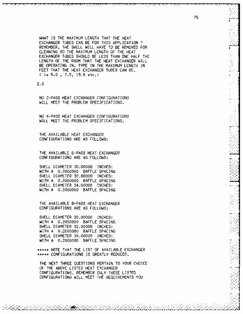
• -~~~~~~ . . . oo.... . , - . . . •
75
WHAT IS THE MAXIMUM LENGTH THAT THE HEATEXCHANGER TUBES CAN BE FOR THIS APPLICATION ?REMEMBER, THE SHELL WILL HAVE TO BE REMOVED FORCLEANING SO THE MAXIMUM LENGTH OF THE HEATEXCHANGER TUBES SHOULD BE LESS THAN ONE HALF THELENGTH OF THE ROOM THAT THE HEAT EXCHANGER WILLBE OPERATING IN. TYPE IN THE MAXIMUM LENGTH INFEET THAT THE HEAT EXCHANGER TUBES CAN BE.< ie 5.0 , 7.5, 19.6 etc.)
2.0
NO 2-PASS HEAT EXCHANGER CONFIGURATIONSWILL MEET THE PROBLEM SPECIFICATIONS.
NO 4-PASS HEAT EXCHANGER CONFIGURATIONSWILL MEET THE PROBLEM SPECIFICATIONS.
THE AVAILABLE HEAT EXCHANGERCONFIGURATIONS ARE AS FOLLOWS:
THE AVAILABLE 6-PASS HEAT EXCHANGERCONFIGURATIONS ARE AS FOLLOWS:
SHELL DIAMETER 30.00000 INCHES:WITH A 0.2000000 BAFFLE SPACINGSHELL DIAMETER 32.00000 INCHES:WITH A 0.2000000 BAFFLE SPACINGSHELL DIAMETER 34.00000 INCHES:WITH A 0.2000000 BAFFLE SPACING
THE AVAILABLE 8-PASS HEAT EXCHANGERCONFIGURATIONS ARE AS FOLLOWS:
SHELL DIAMETER 30.00000 INCHES:WITH A 0.2000000 BAFFLE SPACINGSHELL DIAMETER 32.00000 INCHES:WITH A 0.2000000 BAFFLE SPACINGSHELL DIAMETER 34.00000 INCHES:WITH A 0.2000000 BAFFLE SPACING
•**** NOTE THAT THE LIST OF AVAILABLE EXCHANGER•**** CONFIGURATIONS IS GREATLY REDUCED.
THE NEXT THREE QUESTIONS PERTAIN TO YOUR CHOICEOF THE ABOVE LISTED HEAT EXCHANGERCONFIGURATIONS. REMEMBER ONLY THESE LISTEDCONFIGURATIONS WILL MEET THE REQUIREMENTS YOU
........ ... . . .. . .. . . . .-. . .. . .- . .

76
HAVE INPUT INTO THE PROGRAM
WHAT SHELL DIAMETER DO YOU CHOOSE ? TYPE 12.0,14.0, 28.0 etc.
30.0
WHAT NUMBER OF TUBE PASSES DO YOU CHOOSE ? TYPE2.0, 4.0, 6.0, OR 8.0
6.0
WHAT SHELL BAFFLE SPACING DO YOU CHOOSE ? TYPE0.2, 0.45, OR 1.0
0.2
THE FINAL CONFIGURATION 10
SHELL DIAMETER: 30.0 INCHES
NUMBER OF TUBE-SIDE PASSES: 6.0
BAFFLE SPACING: 0.20 OR
6.00 INCHES
EXCHANGER TUBE LENGTH: 1.925 FEET
TUBE-SIDE PRESSURE LOSS: 1.01 POUNDS PER SQUARE INCH
SHELL-SIDE PRESSURE LOSS: 0.48 POUNDS PER SQUARE INCH
ESTIMATED CAPITAL COST: $ 28282.48
U = 194.6903LICALC = 237.3057
DO YOU WANT TO TRY A DIFFERENT HEAT EXCHANGERCONFIGURATION ? TYPE Y FOR YES AND N FOR NO.
N
DO YOU WANT TO CHANGE ANY OF THE INPUT PARAMETERS
TO THIS PROBLEM ? TYPE Y FOR YES AND N FOR NO
N
DO YOU WANT TO DO ANY OTHER HEAT EXCHANGERPROBLEMS ? TYPE Y FOR VES AND N FOR NO.
NFortran STOP DONE
.- .,°.
. . . . . . . . . . . . . . . . . . . . . . . . . . . . . . . . . . . . . . . . . ...--L: 2 2".' " 'L'-Z-.-...-Z- l":1 .£"< -'.1i . -. =..1- -> ,i- .}L ]--- 9 i- :.'-' i .. i

77
X. CONCLUSION. 4
A. Discussion
The major intent of this thesis was to create a computer program
which would provide the user with quick preliminary sizes of shell and
tube heat exchangers which will accomplish the required heat duty while
meeting the length and pressure drop limitations imposed. This program
was developed with information and equations that are publicly
available. No proprietary code was used. No attempt has been made to
compete with the more sophisticated software of proprietary organiza-
tions such as HTRI and Heat Transfer and Fluid Flow Services (HTFS). It
is the shell and tube exchanger manufacturer's job to squeeze every last
BTU out of a given heat exchanger design and to use every last tenth of
a PSI to shorten the length of an exchanger. Their reason is obvious;
to give the buyer the cheapest, and most effective heat exchanger they
can. While the program that has been developed will not provide the
user the information needed to completely build a shell and tube heat
exchanger, it does provide with reasonable accuracy the key information
that one needs to know: the exchanger length, the exchanger shell
diameter, the shell-side pressure loss, the tube-side pressure loss and
the estimated capital cost. Armed with this information, one can seek
out a manufacturer that will buili the heat exchanger to specifications.
The program developed is very user-friendly. The user can continu-
ally chdnge input parameters to see how the changes affect the final
design options provided. This aspect gives the program some educational
significance. The user can see what happens when a more viscous fluid
is exchanged for a less viscous one. The addition or deletion of the .
. .,

78
fouling factor from the design input can also give the user some insight
into just what a scaling deposit does to the heat transfer in an
exchanger.
The program does indeed accomplish what it was expected to do. The
time-intensive and laborious calculations needed to design a single heat
exchanger have been organized into a compact program which provides
nearly instantaneous results to the user.
B. Suggestions for Improvement
This program is suited to further expansion and revision. The
program is limited to fixed tube sheet type "E" shells, with triangular
tube pitch layout under single-phase liquid-to-liquid low pressure
operations. Any reductions in these limiting features would greatly
enhance the program capabilities. There is sufficient experimental . .
data, equations, and commercial usage data available to widen the scope .-
of the programs uses. The program could be expanded to handle TEMA type
"F", "G", "H", "J", or "X" shells. Square and rotated square tube pitch
layouts could be incorporated. Multiple-phase design can be added as
well as gas-to-gas and gas-to-liquid operations. High pressure opera-
tions could be included.
The program can be expanded to also do more of the mechanical
design. All of the integral parts of the shell and tube heat exchanger
could be designed: the thickness of the tubesheets, the thickness of the
shell, the ize and type of gaskets, the size of the end covers and the
number, type and size of bolts needed to name just a few.
Other improvements may be to increase the selection of fluids
available and to allow for the evaluation of parallel and series heat
exchanger configurations.
• . ..

79
REFERENCES
1. Kakac, S., Bergeles, A.E., and Mayinger, F. Eds Heat Exchangers:
Thermal-Hydraulic Fundamentals and Design. New York, McGraw-Hill
Book Company, (1981), p. 537.
2. TEMA, Standards of Tubular Exchanger Manufacturers Association, 6th
Ed. 1978, p. 135.
3. Singh, Krishna P. and Soler, Alan I., Mechanical Design of Heat
Exchangers. New Jersey, Arcturus Publishers Inc., (1984), p. 16.
4. Chase, A. Timothy, Manager, Special Products Department, Struthers
Wells Corporation, Private Communication, 29 January 1985.
5. Chase, A. Timothy, "Mechanical Design of Heat Transfer Equipment"
Presentation to Philadelphia and Delaware Sections ASME, March 19,
1981.
6. Kakac, S., p. 542. -
7. Fanaritis, J.P., Kwas, J.A., and Chase, A.T., "Heat Exchange
Technology" Encyclopedia of Chemical Technology, New York, John
Wiley & Sons, Inc., (1980), Volume 12, Third Edition, p. 155.
8. Taborek, J., "Evolution of Heat Exchanger Design Techniques," Hedt
Transfer Engineering, (1979), Vol. I., p. 15.
9. Fraas, A.P. and Ozisik, M.N., Heat Exchanger Design. New York, John
Wiley & Sons, Inc., (1965), p. 151.
10. Kakac, S., pp. 581-588.
- ... '.. . .. . . . . . .
%i. . ;274- °.

*~ -- -7-- -
80
11. Tinker, T. "Shell-Side Characteristics of Shell and Tube Heat
Exchangers," Trans ASME, Vol. 80, 1958, pp. 36-49.
12. Fraas, A.P., pp. 151-155.
13. Rohsenow, W.M. and Hartnett, J.P. Eds., Handbook of Heat Transfer.
New York, McGraw-Hill Book Company, (1973), pp. 18-45 to 18-50.
14. Afgan, N.H., and Schlunder, E.U., Eds., Heat Exchangers: Design and
Theoy Sourcebook. New York, McGraw-Hill Book Company, (1974),
pp. 155-168.
15. Sherwood, T.K. "A Review of the Development of Mass Transfer
Theory," C'emical Engineering Education, (1974), p. 49.
16. Taborek, J., pp. 15-16.
17. Chase, A. Timothy, Manager, Special Products Department, Struthers
Wells Corporation, Private Communication, 29 January 1985.
18. Coulson, J.M. and Richardson, J.F., Chemical Engineering. New York,
MacMillan Company, (1964), pp. 259-260.
19. Patterson-Kelley Company, Heat Exchangers. Manual No. 700-A, 1959,
pp. e8 - e9.
20. Adams, A.J. and Rogers D.F., Computer-Aided Heat Transfer Analysis.
New York, McGraw-Hill Book Company, (1973), pp. 368-369.
?1. TEMA, p. 29.
?2. Singh, K. p., pp. 735-735.
..-........................--....- .-... ..........-..-.....--. ,.-.-.-......-......-....,...-...-.,.. -. , ..

81
23. Kacac, S., pp. 1090-1091.
24. TEMA, pp. 138-139.
25. Kacac, S. pp. 1013-1047.
26. Ibid., pp. 1091-1093.
27. Chase, A. Timothy, Manager, Special Products Department, Struthers
Wells Corporation, Private Communication, 29 January 1985.
28. Knutson, J.L., Customer Service Manager, Heresite-Saekaphen, Inc.,
Private Communication, 15 January 1985.
29. Chase, A. Timothy, Manager, Special Products Department, Struthers
Wells Corporation, Private Communication, 29 January 1985.
30. Breeze, James L. "Shell and Tube Heat Exchangers" ASHRAE Journal,
Vol. 26, No. 5 (May 1984), pp. 24-27.
31. Chase, A. Timothy, Manager, Special Products Department, Struthers
Wells Corporation, Private Communication, 29 January 1985.
32. Ibid.
33. Breeze, James L., pp. 24-27.
34. Chase, A. Timothy, Manager, Special Products Department, Struthers
Wells Corporation, Private Communication, 29 January 1985.
35. Kern, Donald Q., Process Heat Transfer. New York, McGraw-Hill Buok
Company (1950), p. 129.
. . . . ..

82
36. Holman, J.P., Heat Transfer. Fifth Edition. New York, McGraw-Hill
Book Company, (1981), p. 456.
37. Kays, W.M. and London, A.L., Compact Heat Exchangers. Third
Edition. New York, McGraw-Hill Book Company, (1984), p. 16.
38. Ibid.
39. Holman, J.P., p. 457.
40. Kays, W.M., p. 23.
41. Kakac, S., pp. 570-573.
42. Kern, Donald Q., pp. 138-139.
43. Fanaritis, J.P., p. 157.
44. Kern, Donald Q., p. 103.
45. TEMA, p. 137.
46. Ibid.
47. Kern, Donald Q., p. 896.
48. Ibid., p. 148.
49. Chase, A. Timothy, Manager, Special Products Department, Struthers
Wells Corporation, Private Communication, 29 January 1985.
50. Kern, Donald Q., p. 147.
51. Ibid., p. 839.
........................................................................- ,', _, ".,?,,,, " %,- " ,, "

83
52. Gaggioli, Richard A., Ed. Efficiency and Costing. Washington,
D.C., American Chemical Society, (1983), pp. 232-233.
53. Shigley, J.E., Mechanical Engineering Design. New York, McGraw-Hill
Book Company, Inc., (1963), p. 220.
.............................................

APPENDIX A
VARIABLE LISTING

This is an alphabetical display of the variables used in the main com-
puter program. Their explanation and units are provided for quick
reference and numerical analysis checks.
Variable Name Explanation Units
ACALC Answer designation to questions asked
in the program.
ACORR Required heat transfer area (calculated). FT2
AFFAC Answer designation to change the fouling -
factor choice.
AFOUL Answer designation to fouling factor
question asked in the program.
AG Gravitational acceleration constant FT/SEC 2
: 32.1740.
AGAIN Answer designation to changing input -
parameters asked in the program.
AL2(1) An array of tube bundle surface areas ,T 2/FT
per foot of tube length for 2-pass
construction.
AL4(1) An array of tube bundle surface areas FT2/FT
per foot of tube length for 4-pass
construction.
7 D-RI53 779 COMPUTER-ADD THERMOYDRULIC DESIGN OF TEMA TYPE E 2/2
SHELL AND TUBE HEAT..(U) ARMY MILITARY PERSONNEL CENTERALEXANDRIA VA N J KOLAR 81 APR 85
UNCLASSIFIED F/G 3/1 NL
MEEOMONEE I
IIIIIIIIIIE

II iii-1.811111 I - 115
MICROCOPY RESOLUTION TEST CHARTNATIONAL BUREAU OF STANDARDS 961 A

Variable Name Explanation Units
2AL6(1) An array of tube bundle surface areas FT /FT
per foot of tube length for 6-pass
construction.!2
AL8(1) An array of tube bundle surface areas FT 2/FT
per foot of tube length for 3-pass
construction.
ALENTH Answer designation to length restriction
question asked in the program.
ALREST Answer designation to change the length
restriction.
AMATE Answer designation to change the tube
material.
AMAXSP Maximum allowable shell-side pressure LB/IN 2
loss.
AMAXTP Maximum allowable tube-side pressure LB/IN 2
loss.
APRES Answer designation of change the
allowable pressure drops.
ARAV Maximum number of tubes possible
depending on available area.
ASC Crossflow area of shell IN2

Variable Name Explanation Units
ASFLU Answer designation to change the shell
fluid.
ASGPM Answer designation to change the shell-
side flow rate.
ASTEM Answer designation to change the shell-
side temperature.
ATFLU Answer designation to change the tube
fluid.
ATGPM Answer designation to change the tube-
side flow rate.
ATI(I) An array of available internal areas of IN2
tubes.
ATIN Choice of internal area of tube. IN2
ATS(I) An array of available external surface FT2/FT
areas of tubes per foot of tube length.
ATSU Choice of external surface area of tube FT2/FT
per foot of tube length.
ATTEM Answer designation to change the tube-
side temperatures.
ATUBE Answer designation to change the tube size. -

Variable Name Explanation Units
C Constant : .3208342 (conversion factor). -
CASE Number representing whether the tube fluid
is being heated or cooled.
CF Cost factor of the tube material choice.
CFM(I) An array of cost factors depending on
material type.
CMAX Capacity rate of the maximum fluid. BTU/HR-°F
CMIN Capacity rate of the minimum fluid. BTU/HR-°F
CP Specific heat at constant pressure BTU/LBM-0 F
value calculated in subroutine.
CPS Specific heat at constant pressure of BTUiLBM-°F
the shell fluid. .
CPT Specific heat at constant pressure of BTU/LBM-°F
the tube fluid.
CS Capacity rate of shell fluid. BTU/HR-0 F
CT Capacity rate of tube fluid. BTU/HR-°F
DEN Density value calculated in subroutine LBM/FT 3
DENS Density of shell fluid. LBM/FT 3
DENT Density of tube fluid. LRM/FT 3
............................................... .. o

.VW * .. r - - -- -, '., - . ,
Variable Name Explanation Units
DENW Density of water for specific gravity LBM/FT 3
calculations.
DEQS Equivalent diameter of the fluid IN
conduit crossing the tubes.
DSI(I) An array of available inside diameters IN
of shells.
DSIU(I) An array of available usable diameters IN
of shells.
OTI(I) An array of available inside diameters IN
of tubes.
DTIN Choice of inside tube diameter. IN
DTO(I) An array of available outside diameters IN
of tubes.
DTOT Choice of outside tube diameter. IN
DV Dynamic viscosity value calcul-3ted in LB/FT-SEC
subroutine.
DVS Dynamic viscosity of shell fluid. LB/FT-SEC
DVFS Dynamic viscosity of shell fluid at LB/FT-SEC
at wall temperature.
DVT Dynamic viscosity of tube fluid. LB/FT-SEC
S*..~'.*.. .'.'. * ... ....- o"*ho'.*-

Variable Name Explanation Units
DVTF Dynamic viscosity of tube fluid at LB/FT-SEC
wall temperature.
EFF Heat transfer effectiveness.
F1 Constant = 0.9069, which accounts for
triangular tube arrangement in calculating
the number of tubes possible for a given
shell diameter.
F2 Factor used in calculating the number of -
tubes possible for a given shell diameter
for 2-pass construction.
F4 Factor used in calculating the number of -
tubes possible for a given shell diameter
for 4-pass construction.
F6 Factor used in calculating the number of "
tubes possible for a given shell diameter
for 6-pass construction.
F8 Factor used in calculating the number of
tubes possible for a given shell diameter
for 3-pass construction.
FRS Shell-side friction factor.
FRT Tube-side friction factor.

Variable Name Explanation Units
2GS Mass velocity of the shell fluid. LB/SEC-FT
GT Mass velocity of the tube fluid. LB/SEC-FT 2
HI Heat transfer film coefficient BTU/HR-°F-FT 2
inside the tubes.
HO Heat transfer film coefficient BTU/HR-OF-FT 2
outside the tubes.
Counter
Counter
J2 Counter
J4 Counter
J6 Counter
J8 Counter
BTUK Thermal conductivity value calculated H "HR.FT2 -°F
in subroutine.
BTUKI Thermal conductivity interim value
HR-FT2_OF
used in subroutines.
K2 Count r
KuK4 Counter
. . . . ... . . . . . . . . . . . . . . .

Variable Name Explanation Units
K6 Counter
K8 Counter
BTU-FTKM(I) An array of thermal conductivities of
HR-FT4_OFmetals.
KS Thermal conductivity of shell fluid.
BTUKT Thermal conductivity of tube fluid.
HR-FT-0 F
BTU-FTKW Choice of thermal conductivity of
HRFT 2_ OFthe tube metal.
L Length of tubing of chosen heat FT
exchanger configuration.
LRESTR Length restriction of the heat FT
exchanger tubes.
MI Counter
M2 Counter
M3 Counter
MS Shell-side fluid flow rate. GPM
MT Tube-side fluid flow rate. GPM
. . . .. . . . . .. . . . . . . . . . . . . . . . .

Variable Name Explanation Units
N Integer designation of shell diameter .
choice.
NP Number designation of number of tube .
passes.
NT2(I) An array of tube counts for 2-pass
construction.
NT4(I) An array of tube counts for 4-pass
construction.
NT6(1) An array of tube counts for 6-pass
construction.
NT8(1) An array of tube counts for 8-pass -
construction.
NTU Number of heat transfer units.
OKFIN Counter representing final OK to
print exchanger configuration.
PI Constant = 3.1415927
PICKD Number designating the choice of IN
shell diameter.
PICKFS Number designating the choice of
fluid in the shell.

Variable Name Explanation Units
PICKFT Number designating the choice of
fluid in the tubes.
PICKM Number desicnating the choice of
metal of the tubing.
PICKP Number designating the choice of
number of tube passes.
PICKS Number designating the choice of
baffle spacing.
PICKT Number designating the choice of
tubing size.
PLSTOT Total shell-side pressure loss. LB/IN 2
PLTF Tube-side pressure loss due to LB/IN 2
friction losses.
DLTR Tube-side pressure loss due to LB/IN 2
return losses.
DLTTOT Total tube-side pressure loss. LB/IN 2
Q Heat transfer rate BTU/HR
QSKIH(I) An array of maximum shell-side flow GrM
rates for .2 baffle spacing construction.
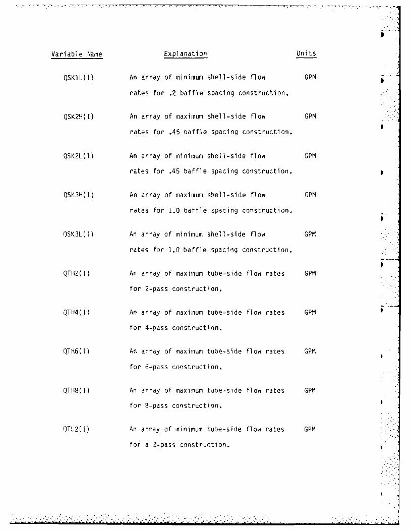
Variable Name Explanation Units
QSK1L(I) An array of minimum shell-side flow GPM
rates for .2 baffle spacing construction.
QSK2H(I) An array of maximum shell-side flow GPMp
rates for .45 baffle spacing construction.
QSK2L(I) An array of minimum shell-side flow GPM
rates for .45 baffle spacing construction.
QSK3H(1) An array of maximum shell-side flow GPM
rates for 1.0 baffle spacing construction.
QSK3L(I) An array of minimum shell-side flow GPM
rates for 1.0 baffle spacing construction.
QTH2(1) An array of maximum tube-side flow rates GPM
for 2-pass construction.
QTH4(1) An array of maximum tube-side flow rates GPM
for 4-pass construction.
QTH6(t) An array of maximum tube-side flow rates GPM
for 6-pass construction.
QTH8(1) An array of maximum tube-side flow rates GPM
for 8-pass construction.
QTL2(t) An array of minimum tube-side flow rates GPM
for a 2-pass construction.
i. , ." i--L- .-.--,-.-'_ '--'--'.. ,.'.'1 .,-..',................,'-.-......."..-.........."..-

Variable Name Explanation Units
QTL4(I) An array of minimum tube-side flow rates GPM
for a 4-pass construction.
QTL6(I) An array of minimum tube-side flow rates GPM
for a 6-pass construction.
QTL8(I) An array of minimum tube-side flow rates GPM
for 8-pass construction.
RATIO Ratio of the minimum capacity fluid to
the maximum capacity fluid.
RES Reynolds number of the shell fluid.
RET Reynolds number of the tube fluid.
HR-FT 2-OFRFOULT Total fouling resistance in the heat
BTUexchanger.
HRFT2 _OFRI Fouling resistance on inside of tubes.
BTU
HR-FT -F
RO Fouling resistance on outside of tubes.BTU
HR-FT4-_0F
RW Resistance of tube wall.BTU
SF(I) An array of shell-side friction factors.

Variable Name Explanation Units
SRE(1) An array of shell-side fluid Reynolds
numbers.
TIMAX Entrance temperature of the maximum fluid. OF
TIMIN Entrance temperature of the minimum fluid. OF
T2MA( Exit temperature of the maximum fluid. OF
T2MIN Exit temperature of the minimum fluid. OF
TAVE Average temperature value used in OF
subroutine calculations.
TC Tube clearance. IN
TF(1) An array of tube-side friction factors
TH Thickness of the partition wall for IN
multiple pass construction.
P(1) An array of available tube pitches of IN
tubes.
TPH Choice of tube pitch. IN
TRATIO Ratio of outside to inside surface of
tubing.
TE(!) An array of tube-side fluid Reynolds
numbers.
. . . . .. . . . . . . . . . . . . . . . . .. . -.

DO 16, 1=1,28
QSK1H(I) = 3.116875*.2O*DSI(I)*DSIU(I)*<TC/TPH)*4.5
16 CONTINUE
*** CALCULATE THE LOW SHELL-SIDE FLOW RATE FOR A BAFFLE*** SPACING OF .45*SHELL DIAMETER (K2) BASED ON A 2 FT/SEC*** FLUID VELOCITY FOR EACH AVAILABLE SHELL DIAMETER
DO 17, 1=1,28
QSK2L(I) = 3.116875*.45*DSI(I)*DSIU(I)*(TC/TPH)*2.O
17 CONTINUE
*** CALCULATE iHE HIGH SHELL-SIDE FLOW RATE FOR A BAFFLE*** SPACING OF .45*SHELL DIAMETER (K2) BASED ON A 4.5 FT/SEC*** FLUID VELOCITY FOR EACH AVAILABLE SHELL DIAMETER
DO 18. I=1.28
QSK2H(I) = 3.116875*.45*D31(1)*DSIU(I)*(TC/TPH)*4.5
18 CONTINUE
*** CALCULATE THE LOW SHELL-SIDE FLOW RATE FOR A BAFFLE*** SPACING OP I.O*3HELL DIAMETER (K3) BASED ON A 2 FT/SEC*** FLUID VELOCITY FOR EACH AVAILABLE SHELL DIAMETER
DO 19. 1=1,28
QSK3L(I) 3.116875*1.0*DSI(I)*DSIU(I)*(TC/TPH)*2.0
19 CONTINUE
*** CALCULATE THE HIGH SHELL-SIDE FLOW RATE FOR A BAFFLE*** SPACING OF 1.O*SHELL DIAMETER (K3 BASED ON A 4.5 FT/SEC*** FLUID VELOCITY FOR EACH AVAILABLE SHELL DIAMETER
DO 20, 1=1,28
QSK3H(I) 3.116875*1.O*O3I(I)*DSIU(I)*(TC/TPH)*4.5
?0 CONTINUE
**. CALCULATE THE CAPACITIES OF THE SHELL AND TUBE FLUIDS
* DEPFNCING ON THE TUBE FLUID CHOICE CALCULATE THE TUBE* FLUID PPOPERTIES Oc DENSITY, SPECIFIC HEAT, DYNAMIC
*** VI,:.COSITY AND THERMAL CONDUCTIVITY
7AdE TTAVE
.......................... ............... ..-- •..•...,...." .......... ". ....- .

QTL4(I) : 3.116875 * NT4(I) * ATIN * 2.0 / 4.0
11 CONTINUE
• ** CALCULATE THE HIGH TUBE-SIDE FLOW RATE FOR A 4-PASS
• * EXCHANGER BASED ON A 8 FT/SEC FLUID VELOCITY FOR EACH
• ** AVAILABLE SHELL DIAMETER
DO 12, 1=1,28
QTH4(I) = 3.116875 * NT4(I) * ATIN * 6.0 / 4.0
12 CONTINUE
** CALCULATE THE LOW TUBE-SIDE FLOW RATE FOR A 2-PASS
• ** EXCHANGER BASED ON A 2 FT/SEC FLUID VELOCITY FOR EACH
• ** AVAILABLE SHELL DIAMETER
JO 13, 1=1,28
QTL2([) = 3.116875 * NT2(I) * ATIN * 2.0 / 2.0
13 CONTINUE
• ** CALCULATE THE HIGH TUBE-SIDE FLOW RATE FOR A 2-PASS
** EXCHANGER BASED ON A 8 FT/SEC FLUID VELOCITY FOR EACH
• ** AVAILABLE SHELL DIAMETER
DO 14, 1=1,28
QTH2(1) = 3.116875 * NT2(I) * ATIN * 8.0 / 2.0
14 CONTINUE
• ** CALCULATE THE TUBE CLEARANCE - THE SPACING BETWEEN THE
• ** TUBES - FROM THE DEFINITION OF TUBE PITCH
TC = TPH - OTOT
*-4, CALCULATE THE LCW SHELL-SIDE FLOW RATE FOR A BAFFLE
• * SPACING OF .2*SHELL DIAMETER (KI) BASED ON A 2 FT/SEC
• -* FLUID VELOCITY FOR EACH AVAILABLE SHELL DIAMETER
DO 15, 1=1,28
QSKIL(1) = 3.116875*.20*DSI(I)*DS!U(I)*(TC/TPH)*2.0
15 CONTINUE
• * CALCULATE THE HIGH SHELL-SIDE FLOW RATE FJR A BAFFLE
SPACING OF .2,SHELL DIAMETER (KI) BASED ON A 4.5 FT,/SEC
** FLUID VELOCITY FcR EACH AVAILABI.E .HELL DIAMETER
. . .

DO 6, I=1,28
AL2(I) = NT2(I) * ATSUAL4(I) = NT4(1) * ATSUAL6(1) = NT6(1) * ATSUAL8(I) = NT8(I) * ATSU
6 CONTINUE
• ** CALCULATE THE LOW TUBE-SIDE FLOW RATE FOR A 8-PASS• ** EXCHANGER BASED ON A 2 FT/SEC FLUID VELOCITY FOR EACH• ** AVAILABLE SHELL DIAMETER
DO 7, 1=1,28
QTL8(I) = 3.116875 * NT8() * ATIN • 2.0 / 8.0
7 CONTINUE
* ** CALCULATE THE HIGH TUBE-SIDE FLOW RATE FOR A 8-PASS• ** EXCHANGER BASED ON A 8 FT/SEC FLUID VELOCITY FOR EACH• ** AVAILABLE SHELL DIAMETER
DO 8, 1=1,28
QTH8(I) = 3.116875 * NT8(1) * ATIN * 8.0 / 8.0
8 CONTINUE
* ** CALCULATE THE LOW TUBE-SIDE FLOW RATE FOR A 6-PASS* ** EXCHANGER BASED ON A 2 FT/SEC FLUID VELOCITY FOR EACH•*** AVAILABLE SHELL DIAMETER
DO 9, 1=1,28
QTL6(I) = 3.116875 * NT6(I) * ATIN * 2.0 / 6.0
3 CONTINUE
• ** CALCULATE THE HIGH TUBE-SIDE FLOW RATE FOR A 6-PASS* ** EXCHANGER BASED ON A 8 FT/SEC FLUID VELOCITY FOR EACH• ** AVAILABLE SHELL DIAMETER
DO 10, 1=1,23
QTH6(I) = 3.116875 * NT6(I) * ATIN * 8.0 / 6.0
10 CONTINUE
S** CALCULATE THE LOW TUBE-SIOE FLOW RATE FOR A 4-PASS** EXCHANGER BASED ON A 2 FT/SEC FLUID VELOCITY FOR EACH• ** AVAILABLE SHELL DIAMETER
DO 11, 1=1,28

IF (AGAIN .EQ. 'Y') THENGO TO 716
END IF
*** THE NUMBER OF TUBES ALLOWABLE IS CALCULATED FOR COMMON*** SHELL DIAMETERS STARTING WITH 6 INCHES AND INCREASING*** IN INCREMENTS OF 2 INCHES TO A MAXIMUM OF 60 INCHES
3 DO 5, I=1,28
IF(DSI(I) .GE. 6.0 .AND. DSI(I) .LE. 18.0) THENTH = 0.25
END IF
IF(DSI(I) .GT. 18.0 .AND. DSI(I) .LE. 36.0) THENTH = 0.50
END IF
IF(DSI(1) .GT. 36.0 .AND. DS(I) .LE. 60.0) THENTH = 0.75
END IF
*** THE USABLE SHELL DIAMETEN IS .5 INCHES LESS THAN THE*** ACTUAL SHELL DIAMETER DUtl TO TUBE SHEET CONSTRUCTION
DSIU(I) = (DS1(1) - 0.5)
F1 = 0.9063
F2 = 1.0 - ((TH * DSIU(I))/((PI/4.0)*(DSIU(I)**2.0)))
ARAV ((DSIU(I) - DTOT)/TPH)**2.0
NT2(I) = ARAV * Fl * F2
F4 = 1.O-(2.125+TH DSIU(I))((Pl/4.0)*(DSIU(I)**2.O)))
NT4(I = ARAV * Fl * F4
F6 = 1.0-((3.25,TH * DS1U(8)/( PI/4.O)*(D1IU(1)**2.0)
NT6(1) = ARAV * Fl P6
F6 = l.0-((4.0*TH * OSIUtI))/((PI/4.3)*(DSIU(I'**2.O))
NTS(1) = ARAV * Ft F8
CONTINUE
*** CALCULATE THE AVAILABLE TUBE SURFACE AREA PER rOOT OF**- L:NGTH OF THE HEAT ECHANGER FOR EACq AVAILABLE SHELL
DIAMETER
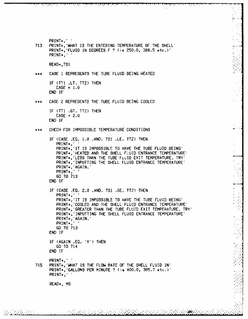
- -
PRINT*,'713 PRINT*,'WHAT IS THE ENTERING TEMPERATURE OF THE SHELL'
PRINT*,'FLUID IN DEGREES F ? (ie 250.0, 366.5 etc.)'PRINT*,'
READ*,TSI
*** CASE I REPRESENTS THE TUBE FLUID BEING HEATED
IF (TT1 .LT. TT2) THENCASE = 1.0
END IF
*** CASE 2 REPRESENTS THE TUBE FLUID BEING COOLED
IF (TTI .GT. TT2) THENCASE = 2.0
END IF
*** CHECH FOR IMPOSSIBLE TEMPERATURE CONDITIONS
IF (CASE .EQ. 1.0 .AND. TSI .LE. TT2) THENPRINT*,'PRINT*,'IT IS IMPOSSIBLE TO HAVE THE TUBE FLUID BEING'PRINT*,'HEATED AND THE SHELL FLUID ENTRANCE TEMPERATURE'PRINT*,'LESS THAN THE TUBE FLI-ID EXIT TEMPERATURE. TRY'PRINT*,'INPUTTING THE SHELL FLUID ENTRANCE TEMPERATURE'PRINT*,'AGAIN.'PRINT*,'GO TO 713
END IF
IF (CASE .EQ. 2.0 .AND. TS1 .GE. TT2) THENPRINT*,'PRINT*,'IT IS IMPOSSIBLE TO HAVE THE TUBE FLUID BEING'PRINT*,'COOLED AND THE SHELL FLUID ENTRANCE TEMPERATURE'PRINT*,'GREATER THAN THE TUBE FLUID EXIT TEMPERATURE. TRY'PRINT*,'INPUTTING THE SHELL FLUID ENTRANCE TEMPERATURE'PRINT*, 'AGAIN.'PRINT*,'GO TO 713
END IF
IF (AGAIN .EQ. 'Y') THENGO TO 714
END IF
PRINT*,'715 PRINT*,'WHAT IS THE FLOW RATE OF THE SHELL FLUID IN'
PRINT*,'GALLONS PER MINUTE ? (ie 400.0, 385.7 etc.)'PRINT*,-
READ*, MS
"" : w m. . . ............................ ° J'.. .. Id "' ' ' " ' --
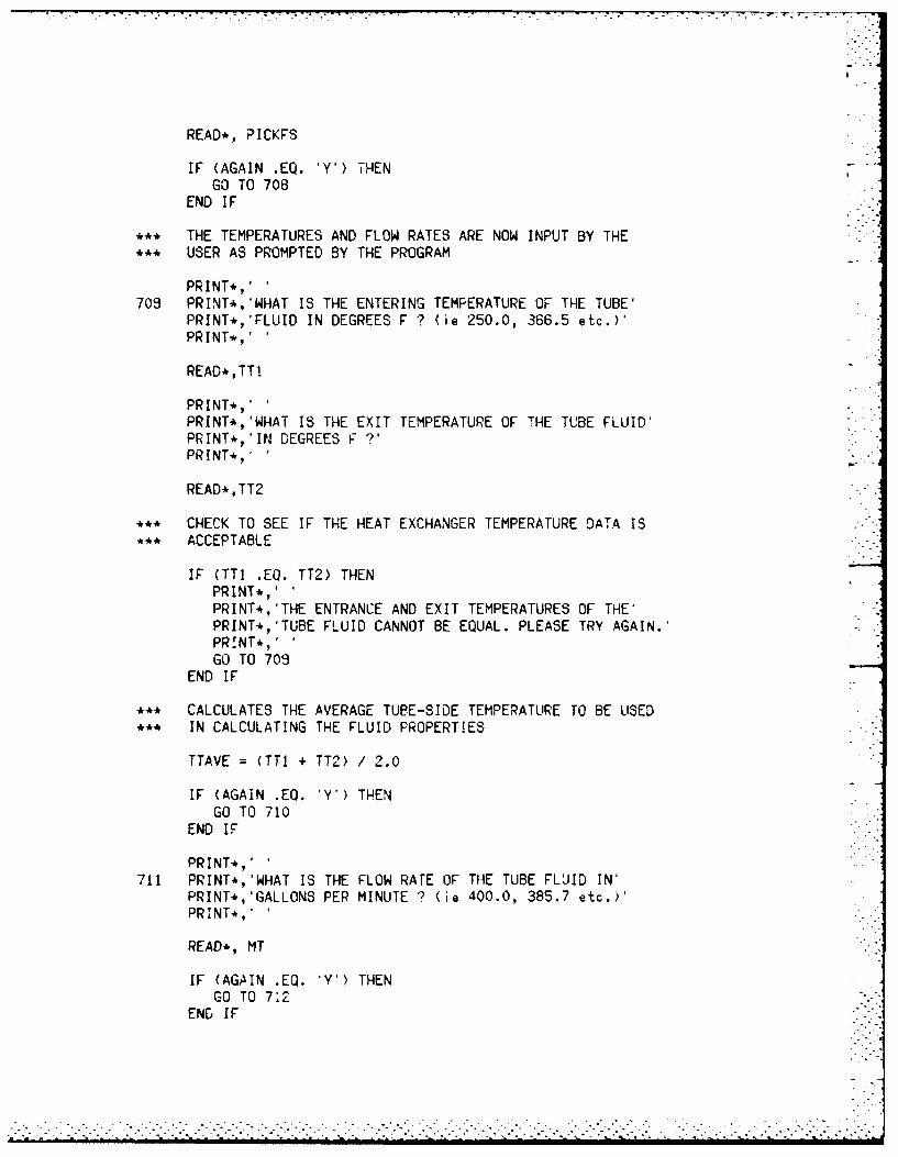
READ*, PICKFS
IF (AGAIN EQ. 'Y') THENGO TO 708
END IF
** THE TEMPERATURES AND FLOW RATES ARE NOW INPUT BY THE•** USER AS PROMPTED BY THE PROGRAM
PRINT*,'709 PRINT*,'WHAT IS THE ENTERING TEMPERATURE OF THE TUBE'
PRINT*,'FLUID IN DEGREES F ? (ie 250.0, 366.5 etc.)'PRINT*,'
READ*,TTI
PRINT*,'PRINT*,'WHAT IS THE EXIT TEMPERATURE OF THE TUBE FLUID'PRINT*,'IN DEGREES FPRINT*,'
READ*,TT2
** CHECK TO SEE IF THE HEAT EXCHANGER TEMPERATURE DATA IS•*** ACCEPTABLE
IF (TTI .EQ. TT2) THENPRINT*,'PRINT*,'THE ENTRANCE AND EXIT TEMPERATURES OF THE'PRINT*,'TUBE FLUID CANNOT BE EQUAL. PLEASE TRY AGAIN.'PR!NT*,'GO TO 709
END IF
S** CALCULATES THE AVERAGE TUBE-SIDE TEMPERATURE TO BE USED• ** IN CALCULATING THE FLUID PROPERTIES
TTAVE = (TTI + TT2) / 2.0
IF (AGAIN .EQ. 'Y') THENGO TO 710
END IF
PRINT*,'711 PRINT*,'WHAT IS THE FLOW RATE OF THE TUBE FLUID IN'
PRINT*,'GALLONS PER MINUTE ? (ie 400.0, 385.7 etc.)'PRINT*,.
READ*, MT
IF (AGAIN .EQ. 'Y') THENGO TO 7:2
END IF
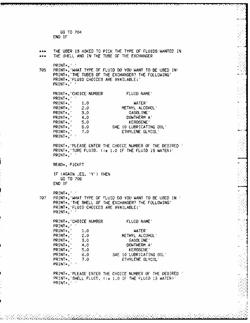
GO TO 704END IF
** THE USER IS ASKED TO PICK THE TYPE OF FLUIDS WANTED IN** THE SHELL AND IN THE TUBE OF THE EXCHANGER
PRINT*,'705 PRINT*,'WHAT TYPE OF FLUID DO YOU WANT TO BE USED IN'
PRINT*,'THE TUBES OF THE EXCHANGER? THE FOLLOWING'PRINT*,'FLIID CHOICES ARE AVAILABLE:'PRINT*.,'
PRINT*,'CHOICE NUMBER FLUID NAME'PRINT*,'PRINT*,' 1.0 WATER'PRINT*,' 2.0 METHYL ALCOHOL'PRINT* , 3.0 GASOLINE'PRINT* , 4.0 DOWTHERM A'PRINT* , 5.0 KEROSENE'PRINT* , 6.0 SAE 10 LUBRICATING OIL'PRINT* , 7.0 ETHYLENE GLYCOL'PRINT*,'
PRINT*,'PLEASE ENTER THE CHOICE NUMBER OF THE DESIREDPRINT*,'TUBE FLUID. (ie 1.0 IF THE FLUID 1S WATER)'PRINT* ,
READ*, PICKFT ww
IF (AGAIN .EQ. 'Y') THENGO TO 706
END IF
PRINT* ,707 PRINT*,'WHAT TYPE OF cLUID DO YOU WANT TO BE USED IN
PRINT*,'THE SHELL OF THE EXCHANGER? THE FOLLOWING'PRINT*,'FLUID CHOICES ARE AVAILABLE:'PRINT*,'
PRINT*,'CHOICE NUMBER FLUID NAME'PRINT*,'PRINT*,' 1.0 WATER'PRINT*,' 2.0 METHYL ALCOHOL'PRINT* , 3.0 GASOLINE'PRINT*,' 4.0 DOWTHERM A'PRINT*,' 5.0 KEROSENE'PRINT*.' 6.0 SAE 10 LUBRICATING OIL'PRINT*,' 7.0 ETHYLENE GLYCOL'PRINT*,'
PPRINT*,)PLEASE ENTER THE CHOICE NUMBER OF THE DESIREDPR!NT4,'SHELL FLUID. (ie 1.0 IF THE F-LUID '43 WAATER)'PRINT*,'

OTOT = OTO(I)DTIN = DTI(I)ATIN = ATI(I)ATSU = ATS(I)TPH = TP(I)PI 3.1415327
IF (AGAIN .EQ. 'Y') THENGO TO 702
END IF
** MATERIAL SPECIFICATIONS OF THE TUBING IS MADE
PRINT*,'703 PRINT*,'WHAT MATERIAL SPECIFICATIONS DO YOU WANT FOR'
PRINT*,'THE TUBING ?
PRINT*,''PRINT*,'CHOICE NUMBER MATERIAL TYPEPRINT*,'PRINT*,' 1.0 ALUMINUM TYPE 1100'PRINT* , 2.0 ALUMINUM TYPE 3003'PRINT*,' 3.0 ALUMINUM TYPE 3004'PRINT* , 4.0 ALUMINUM TYPE 6061'PRINT* , 5.0 ALUMINUM TYPE 6063'PRINT*,' 6.0 CARBON STEEL'PRINT* , 7.0 CARBON MOLY STEEL'PRINT*,' 8.0 CHROME MOLY STEEL (1%)'PRINT* ,' 9.0 CHROME MOLY STEEL (2.25%>'PRINT*,' 10.0 CHROME MOLY STEEL (5%)'PRINT*,' 11.0 CHROME MOLY STEEL (12%)'PRINT*,' 12.0 STAINLESS STEEL (18%)'PRINT*,' 13.0 STAINLESS STEEL (25%)'PRINT*,' 14.0 ADMIRALTY METAL'PRINT*,' 15.0 COPPER'PRINT*,' 16.0 NICKEL'PRINT* , 17.0 ZIRCONIUM'PRINT* , 18.0 TITANIUM'PRINT*,'
PRINT*,'PLEASE ENTER THE CHOICE NUMBER OF THE TYPE OFPRINT*,'MATERIAL DESIRED.(ie 1.0 6.0 18.0 etc.)'PRINT* ,
READ* ,PICKM
I = INT(PICKM)
SMATERIAL PROPERTIES ARE SET ONCE A CHOICE IS MADE
KW =KM(I)
CF CFM(I)
IF (AGAIN .EQ. Y)TE

PRINT*,'PRINT*,'CHOICE NUMBER OUTSIDE DIAMETER(IN) BWG *PRINT*,'PRINT*, 1.0 0.75 10'PRINT., 2.0 0.75 11'PRINT*, 3.0 0.75 12'PRINT* 4.0 0.75 13'PRINT* 5.0 0.75 14'PRINT*,' 6.0 0.75 15'PRINT*, 7.0 0.75 16'PRINT*,' 8.0 0.75 17'PRINT*, 9.0 0.75 18'PRINT*, 10.0 0.75 19'PRINT*., 11.0 0.75 20'PRINT*,PRINT*, 12.0 1.0 8PRINT*, 13.0 1.0 10'PRINT*, 14.0 1.0 illPRINT*, 15.0 1.0 12'PRINT*, 16.0 1.0 13'PRINT*,' 17.0 1.0 14'PRINT*" 18.0 1.0 15'PRINT*,' 19.0 1.0 16'PRINT* 20.0 1.0 18-PRINT-,' 21.0 1.0 20'PRINT*,'PRINT*, 22.0 1.25 7'PRINT*, 23.0 1.25 8'PRINT*, 24.0 1.25 10•PRINT*,' 25.0 1.25 11'PRINT*, 26.0 1.25 12'PRINT*, 27.0 1.25 13'PRINT*, 28.0 1.25 14'PRINT*,' 29.0 1.25 16'PRINT*, 30.0 1.25 17'PRINT*, 31.0 1.25 18'PRINT*,' 32.0 1.25 20'PRINT*,'PRINT*,' 33.0 1.5 10'PRINT*,' 34.0 1.5 12PRINT*,' 35.0 1.5 14'PRINT*.,' 36.0 1.5 16PRINT*,'
PRINT*,'PLEASE ENTER THE CHOICE NUMBER OF THE TYPE OFPRINT*,'TUBING DESIRED.(ie 1.0 6.0 34.0 etc.)'PRINT*,'
READ*,PICKT
I = INT(PICKT)
.** TUBE DIMENSION VARIABLE3 AQE SET ONCE A CHOICE IF MADE
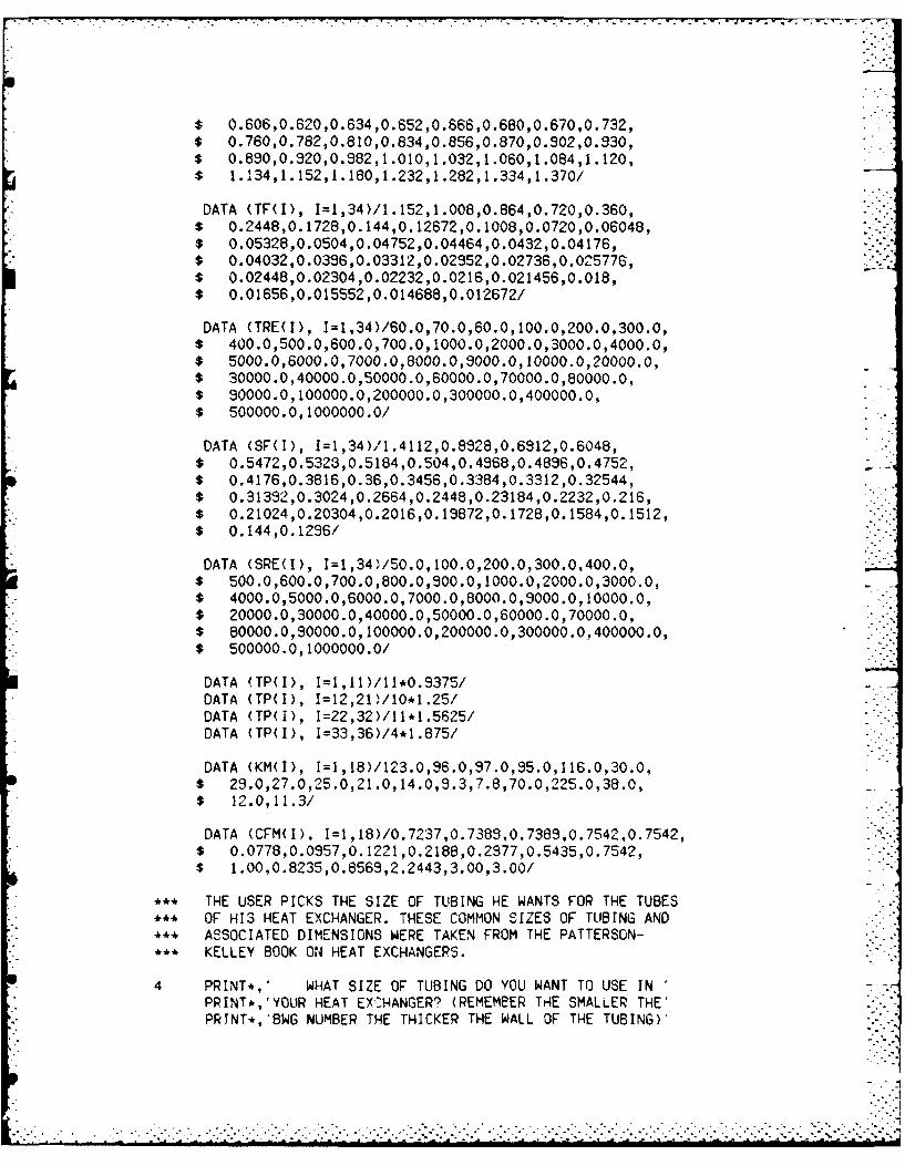
$ 0.606,0.620,0.634,0.652,0.666,0.680,0.670,0.732,$ 0.760,0.782,0.810,0.834,0.856,0.870,0.902,0.930,$ 0.890,0.920,0.982,1.010,1.032,1.060,1.084,1.120,$ 1.134,1.152,1.180,1.232,1.282,1.334,1.370/
DATA (TF(1), I=1,34)/1.152,1.008,0.864,0.720,0.360,$ 0.2448,0.1728,0.144,0.12672,0.1008,0.0720,0.06048,$ 0.05328,0.0504,0.04752,0.04464,0.0432,0.04176,$ 0.04032,0.0396,0.03312,0.02952,0.02736,0.05776,$ 0.02448,0.02304,0.02232,0.0216,0.021456,0.018,$ 0.01656,0.015552,0.014688,0.012672/
DATA (TRE(I), I=1,34)/60.0,70.0,80.0,100.0,200.0,300.0,$ 400.0,500.0,600.0,700.0,1000.0,2000.0,3000.0,4000.0,$ 5000.0,6000.0,7000.0,8000.0,9000.0,10000.0,20000.0,$ 30000.0,40000.0,50000.0,60000.0,70000.0,80000.0,$ 90000.0,100000.0,200000.0,300000.0,400000.0,$ 500000.0,1000000.0/
DATA (SF(I), I=1,34)/1.4112,0.8928,0.6912,0.6048,$ 0.5472,0.5323,0.5184,0.504,0.4968,0.4896,0.4752, - -
$ 0.4176,0.3816,0.36,0.3456,0.3384,0.3312,0.32544,$ 0.31392,0.3024,0.2664,0.2448,0.23184,0.2232,0.216,$ 0.21024,0.20304,0.2016,0.19872,0.1728,0.1584,0.1512,$ 0.144,0.1286/
DATA (SRE(I), 1=1,341/50.0,100.0,200.0,300.0,400.0,$ 500.0,600.0,700.0,800.0,900.0,1000.0,2000.0,3000.0,$ 4000.0,5000.0,6000.0,7000.0,8000.0,9000.0,10000.0,$ 20000.0,30000.0,40000.0,50000.0,60000.0,70000.0,$ 80000.0,90000.0,100000.0,200000.0,300000.0,400000.0,$ 500000.0,1000000.0/
DATA (TP(1), I=1,11)/11*0.9375/DATA (TP(I), I=12,21)/10*1.25/DATA (TP(1), I=22,32)/11*1.5625/DATA (TP(I), 1=33,36)/4*1.875/
DATA (KM(I), I=1,18)/123.0,96.0,97.0,95.0,116.0,30.0,$ 29.0,27.0,25.0,21.0,14.0,9.3,7.8,70.0,225.0,38.0,$ 12.0,11.3/
DATA (CFM(I), I=1,18)/0.7237,0.7389,0.7389,0.7542,0.7542,$ 0.0778,0.0957,0.1221,0.2188,0.2977,0.5435,0.7542,$ 1.00,0.8235,0.8569,2.2443,3.00,3.00/
*** THE USER PICKS THE SIZE OF TUBING HE WANTS FOR THE TUBES*** OF HI3 HEAT EXCHANGER. THESE COMMON SIZES OF TUBING AND**, ASSOCIATED DIMENSIONS WERE TAKEN FROM THE PATTERSON-*** KELLEY BOOK ON HEAT EXCHANGERS.
4 PRINT*,' WHAT SIZE OF TUBING DO YOU WANT TO USE INPRINT*,'YOUR HEAT EXCHANGER? (REMEMBER TrE SMALLER THE'PRINT*,'BWG NUMBER THE THICKER THE WALL OF THE TUBING)'

PRINT*,.' INPUT DATA UNITS'PRINT*,'PRINT*,'TUBE FLUID ENTRANCE TEMP DEGREES F'PRINT*, TUBE FLUID EXIT TEMP DEGREES F'PRINT*,'TUBE FLUID FLOW RATE GALLONS PER MINUTE'PRINT*,'SHELL FLUID ENTRANCE TEMP DEGREES F'PRINT*,'SHELL FLUID FLOW RATE GALLONS PER MINUTE'PRINT*,'MAXIMUM TUBE LENGTH FEET'PRINT*,'MAX TUBE PRESSURE LOSS POUNDS PER SQUARE INCH'PRINT*,.'MAX SHELL PRESSURE LOSS POUNDS PER SQUARE INCH'PRINT*,'
PRINT,,'WHEN YOU ARE READY TO PROCEED TYPE Y <RET>.'READ (5,101) ACALC
PRINT*, THE MAJOR SOURCES OF INFORMATION USED TOPRINT*, FORMULATE THIS PROGRAM ARE:'PRINT*,'PRINT*,'BREESE,J. - SHELL AND TUBE HEAT EXCHANGERS'PRINT*,'KAYS & LONDON - COMPACT HEAT EXCHANGERS'PRINT*,'KERN,D. - PROCESS HEAT TRANSFER'PRINT*,'HOLMAN,J.P. - HEAT TRANSFER'PRINT*, 'CHASET.A. - PERSONAL COMMUNICATION'PRINT*, 'FANARITIS,J.P. - HEAT EXCHANGER TECHNOLOGY'PRINT*, GAGGIOLI,R.A. - EFFICIENCY AND COSTING'PRINT*, PATTERSON-KELLEY CO. - HEAT EHCHANGERS'PRINT*,'TEMA - STANDARDS OF TUBULAR EXCHANGERS'PRINT*,'
PRINT*,'WHEN YOU ARE READY TO PROCEED TYPE Y <RET>.'READ (5,101) ACALC
DATA (DSI(1), I=1,28)/6.0,8.0,10.0,12.0,14.0,16.0,18.0,$ 20.0,22.0,24.0,26.0,28.0,30.0,32.0,34.0,36.0,38.0,$ 40.0,42.0,44.0,46.0,48.0,50.0,52.0,54.0,56.0,58.0,$ 60.0/
DATA (DTO(I), I=1,11)/11*0.75/DATA (DTO(1), I=12,21)/10*1.0/DATA (DTO(t), I=22,32)/I1*1.25/DATA (OTO(I), 1=33,36)/4*1.50/
DATA (ATI(I), I=1,36)/0.1822,0.2043,0.223,0.247,0.268,$ 0.289,0.302,0.314,0.334,0.348,0.363,0.355,0.421,$ 0.455,0.479,0.515,0.546,0.576,0.504,0.639,0.679,$ 0.622,0.662,0.757,0.801,0.838,0.882,0.923,0.385,$ 1.012,1.042,1.092,1.132,1.291,1.397,1.474/
DATA (ATS(1), I=1.1I)/11*0.1563/DATA (ATS(1), I=12,2,P/10*0.2618/DATA 'ATS(1), I=22,32)/11*0.3272/DATA (ATS(1), 1=33,36)/4*0.3927/
DATA (DTI(I), I=1,36;/0.482,0.510,0.532,0.580,0.584,
=." . • . . . .. . . . . . . .... . . .. . .. .... . .. . . . .
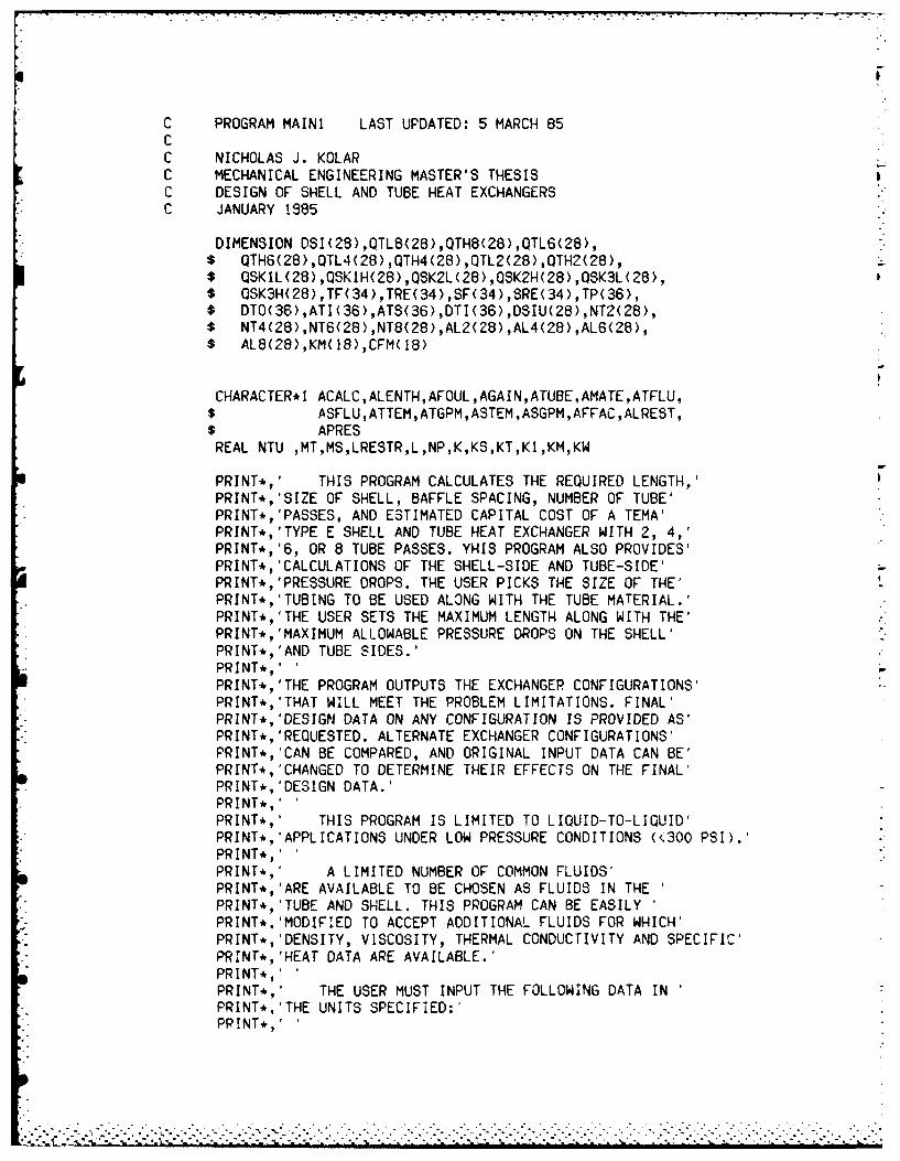
C PROGRAM MAINI LAST UPDATED: 5 MARCH 85CC NICHOLAS J. KOLARC MECHANICAL ENGINEERING MASTER'S THESISC DESIGN OF SHELL AND TUBE HEAT EXCHANGERSC JANUARY 1985
DIMENSION DSI(28),QTL8(28),QTH8(28),QTL6(28),$ QTH6(28),QTL4(28),QTH4(28),QTL2(28),QTH2(28),$ QSKIL(28),QSKIH(28),QSK2L(28),QSK2H(28),QSK3L(28),$ QSK3H(28),TF(34),TRE(34),SF(34),SRE(34),TP(36),$ DTO(36),ATI(36),ATS(36),DTI(36),DSIU(28),NT2(28),$ NT4(28),NT6(28),NT8(28),AL2(28),AL4(28),AL6(28),$ AL8(28),KM(18),CFM(18)
CHARACTER*I ACALC,ALENTH,AFOUL,AGAIN,ATUBE,AMATE,ATFLU,$ ASFLU,ATTEM,ATGPM,ASTEM,ASGPM,AFFAC,ALREST,$ APRESREAL NTU ,MT,MS,LRESTR,L,NP,K,KS,KT,K1,KM,KW
PRINT*, THIS PROGRAM CALCULATES THE REQUIRED LENGTH,'PRINT*,'SIZE OF SHELL, BAFFLE SPACING, NUMBER OF TUBE'PRINT*,PASSES, AND ESTIMATED CAPITAL COST OF A TEMA'PRINT*,'TYPE E SHELL AND TUBE HEAT EXCHANGER WITH 2, 4,'PRINT*,'6, OR 8 TUBE PASSES. YHIS PROGRAM ALSO PROVIDES'PRINT*,'CALCULATIONS OF THE SHELL-SIDE AND TUBE-SIDE'PRINT*,'PRESSURE DROPS. THE USER PICKS THE SIZE OF THE'PRINT*,'TUBING TO BE USED ALONG WITH THE TUBE MATERIAL.'PRINT*, THE USER SETS THE MAXIMUM LENGTH ALONG WITH THE'PRINT*"MAXIMUM ALLOWABLE PRESSURE DROPS ON THE SHELL'PRINT*'AND TUBE SIDES.'PRINT*,'PRINT*, THE PROGRAM OUTPUTS THE EXCHANGER CONFIGURATIONS'PRINT*,THAT WILL MEET THE PROBLEM LIMITATIONS. FINAL'PRINT*,'DESIGN DATA ON ANY CONFIGURATION IS PROVIDED AS'PRINT*,'REQUESTED. ALTERNATE EXCHANGER CONFIGURATIONS'PRINT*,'CAN BE COMPARED, AND ORIGINAL INPUT DATA CAN BE'PRINT*,'CHANGED TO DETERMINE THEIR EFFECTS ON THE FINAL'PRINT*,'DESIGN DATA.'PRINT*,'PRINT*,' THIS PROGRAM IS LIMITED TO LIQUID-TO-LIQUID'PRINT*,'APPLICATIONS UNDER LOW PRESSURE CONDITIONS (<300 PSI).'PRINT*,'PRINT*, A LIMITED NUMBER OF COMMON FLUIDS'PRINT*, ARE AVAILABLE TO BE CHOSEN AS FLUIDS IN THEPRINT*, TUBE AND SHELL. THIS PROGRAM CAN BE EASILYPRINT*,'MODIFIED TO ACCEPT ADDITIONAL FLUIDS FOR WHICH'PRINT*,'DENSITY, VISCOSITY, THERMAL CONDUCTIVITY AND SPECIFIC'PRINT*,'HEAT DATA ARE AVAILABLE.'PRINT*,'PRINT*, THE USER MUST INPUT THE FOLLOWING DATA INPRINT*,'THE UNITS SPECIFIED:'PRINT*,'
* * "
APPENDIX B
MAIN PROGRAM LISTING

Variable Name Explanation Units
TSAVE Average temperature of the shell fluid. OF
TS1 Entrance temperature of the shell fluid. OF
TS2 Exit temperature of the shell fluid. OF
TS2NEW Adjusted exit temperature of the shell OF
fluid.
TTAVE Average temperature of the tube fluid. OF
TT1 Entrance temperature of the tube fluid. OF
TT2 Exit temperature of the tube fluid. OF
BTUU Average overall heat transfer coef- HR-FT 2 _oF
ficient of the exchanger (estimated).
BTUUC Average overall heat transfer coef-
HR-FT 2 _°Fficient of exchanger with clean tubes.
BTU
UCALC Overall heat transfer coefficient ofHR-FT 2-°F
the exchanger (calculated).
VS Shell fluid velocity. FT/SEC
VT Tube fluid velocity. FT/SEC
Z Estimated capital cost of the $
exchanger.
. . . ., . , . . .. . , . , , , , . .. . . , . , . . . . . . . ., - , -. . . - ' . . . ,
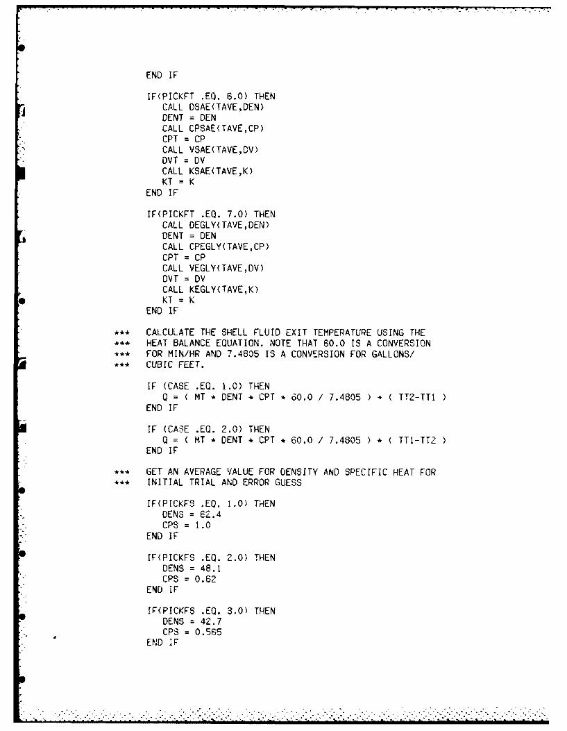
END IF
IF(PICKFT .EQ. 6.0) THENCALL DSAE(TAVE,DEN)DENT = DENCALL CPSAE(TAVE,CP)CPT = CPCALL VSAE(TAVE,DV)DVT = DVCALL KSAE(TAVEK)KT = K
END IF
IF(PICKFT .EQ. 7.0) THENCALL DEGLY(TAVE,DEN)DENT = DENCALL CPEGLY(TAVE,CP)CPT = CPCALL VEGLY(TAVE,DV)DVT = DVCALL KEGLY(TAVE,K)KT = K
END IF
44, CALCULATE THE SHELL FLUID EXIT TEMPERATURE USING THE*4, HEAT BALANCE EQUATION. NOTE THAT 60.0 Is A CONVERSION*** FOR MIN/HR AND 7.4805 IS A CONVERSION FOR GALLONS/*** CUBIC FEET.
IF (CASE .EQ. 1.0) THENQ = ( MT * DENT * CPT * 60.0 / 7.4805 ) * ( TT2-TT1
END IF
IF (CASE .EQ. 2.0) THENQ = ( MT * DENT * CPT * 60.0 / 7.4805 ) * ( TTI-TT2 )
END IF
444 GET AN AVERAGE VALUE FOR DENSITY AND SPECIFIC HEAT FOR*** INITIAL TRIAL AND ERROR GUESS
IF(PICKFS .EQ. 1.0) THENDENS = 62.4CPS = 1.0
END IF
IF(PICKFS .EQ. 2.0) THENDENS = 48.1CPS = 0.62
END iF
IF(PICKFS .EQ. 3.0) THENDENS = 42.7CPS = 0.565
END IF

IF(PICKFT .EQ. 1.0) THENCALL DWATER(TAVE,DEN)DENT = DENCALL CPWATR(TAVE,CP)CPT = CPCALL VWATER(TAVE,DV)DVT = DVCALL KWATER(TAVEK)KT = K
END IF
IF(PICKFT .EQ. 2.0) THENCALL DMETH(TAVE,DEN)DENT = DENCALL CPMETH(TAVE,CP)CPT = CPCALL VMETH(TAVE,DV)DVT = DVCALL KMETH(TAVE,K)KT = K
END IF
IF(PICKFT .EQ. 3.0) THENCALL DGAS(TAVE,DEN)DENT = DENCALL CPGAS(TAVE,CP)CPT = CPCALL VGAS(TAVE,DV)DVT = DVCALL KGAS(TAVE,K)KT = K
END IF
IF(PICKFT .EQ. 4.0) THENCALL DDOWA(TAVE,DEN)DENT = DENCALL CPDOWA(TAVE,CP)CPT = CPCALL VDOWA(TAVE,DV)DVT = DVCALL KDOWA(TAVE,K)KT = K
END IF
IF(PICKFT .EQ. 5.0) THENCALL DKERO(TAVE,DEN)DENT = DENCALL CPKERO(TAVE,CP)CPT = CPCALL VKERO(TAVE,DV)DVT = DVCALL KKERO(TAVE,K)KT = K
.

IF(PICKFS .EQ. 4.0) THENDENS =56.8
CPS =0.60
IF(PICKFS .EQ. 5.0) THENDENS =44.4
CPS =0.60
END IF
IF(PICKFS .EQ. 6.0) THENDENS =52.25
CPS =0.52
END IF
IF(PICKFS .cQ. 7.0) THENDENS =66.2
CPS =0.644
END IF
** SOLVE HEAT BALANCE EQUATION FOR INITIAL GUESS OF SHELL** FLUID EXIT TEMPERATURE
IF (CASE .EQ. 1.0) THENTS2 =TS1 - (0/ ( MS *DENS *CPS *60.0 /7.4805))
END IF
IF (CASE .EQ. 2.0) THENTS2 =TSI + (Q/ (MS *DENS *CPS *60.0 /7.4805))
END IF
* CALCULATE THE SHELL FLUID PROPERTIES BASED UPON THE** AVERAGE TEMPERATURE OF THE SHELL FLUID
48 TSAVE =(TS2+TS1) / 2.0TAVE =TSAVE
IF(PICKFS .EQ. 1.0) THENCALL OWATER( TAVE ,DEN)DENS = DENCALL CPWATR( TAVE ,CP)CPS = CPCALL VWATER (TAVE ,DV),DVS = DVCALL KWATER(TAVE,K)KS = K
END IF
IF(PICKFS .EQ. 2.0) THENCALL DMETH( TAVE ,DEN)DENS = DENCALL CP'IETH( TAVE ,CP)CPS =CP

CALL VMETH(TAVE,DV)DVS =DV
CALL KMETH(TAVE,K)KS =K
END IF
IF(PICKFS .EQ. 3.0) THENCALL DGAS(TAVE,DEN)DENS = DENCALL CPGAS(TAVE,CP)CPS = CPCALL VGAS(TAVE,DV)DVS = DVCALL KGAS(TAVE,K)KS = K
END IF
IF(PICKFS .EQ. 4.0) THENCALL DDOWA( TAVE ,DEN)DENS = DENCALL CPDOWA( TAVE,CP)CPS = CPCALL VDOWA(TAVE,DV)DVS = DVCALL KDOWA(rAVE,K)KS = K
END IF
IF(PICKFS .EQ. 5.0) THENCALL DKERO( TAVE ,DEN)DENS = DENCALL CPKERO( TAVE ,CP)CPS =CPCALL VKERO(TAVE,DV)DVS = DVCALL KKERO(TAVE,K)KS = K
END IF
IF(PICKFS .EQ. 6.0) THENCALL DSAE( TAVE ,DEN)DENS = DENCALL CPSAE(TAVE,CP)CPS CPCALL VSAE(TAVE,DV)DVS = VCALL KSAE(TAVE,K)KS = K
END IF
IF(PICKFS .EQ. 7.0) THENCALL DEGLY(TAVE,DEN)DENS = DENCALL CPEGLV(7AVE,CP)

CPS = CPCALL VEGLY(TAVE,DV)DVS = DvCALL KEGLY(TAVE,K)KS =K
END IF
** RECHECK SHELL EXIT TEMPERATURE CALCULATION USING NEW** VALUES FOR DENSITY AND SPECIFIC HEAT OF THE SHELL FLUID
IF (CASE .EQ. 1.0) THENTS2NEW =TSI - (Q MS * DENS * CPS * 60.0 / 7.4805))
END IF
IF (CASE .EO. 2.0) THENTS2NEW =TSI + (Q /(MS * DENS * CPS * 60.0 / 7.480'5))
END IF
IF (ASS (T82-TS2 NEW) .GT. 1.0) THENT5.2 =TS2NEWGO TO 48
END IF
** DETERMINE WHICH FLUID HAS THE '-AXIMUM CAPACITY RATE FOR** USE IN THE NTU METHOD
CS = MS * DENS * CPS * 60.0 / 7.4805
CT = MT * DENT * CPT * 60.0 / 7.4805
IF (CS .GE. CT) THENCHIN = CTTIMIN =TTLT2MIN = TT2CMAX =CS
TIMAX = TS1T2MAX =TS2
EL SECHIN =CS
TIMIN = T31TZrMIN =TS2CMAX =CT
TIMAX =TTI
T2MAX 7 T2END IF
** CALCULATE THE HEAT TRANSFER EFFECTIVENESS
EFF =ABS(T2MIN -TWMIN) /AB8(T1MAX-TlMIN)
** CHECK FOR IMPOSSIBLE CONDITIONS
.F (EFF .GT. 1.0) THENPRINT*.'

PRINT*,'THE TEMPERATURES PROVIDED AS INPUT ARE SUCH'PRINT*,THAT THE HEAT EXCHANGER WOULD BE REQUIRED TO'PRINT*,'ACCOMPLISH AN IMPOSSIBLE FAT. THE MAXIMUM'PRINT*,POSSIBLE HEAT TRANSFER FOP AN EXCHANGER OF'PRINT*,'INFINITE LENGTH IS LESS THAN WHAT YOU REQUIRE'PRINT*,THIS HEAT EXCHANGER TO ACCOMPLISH. TRY'PRINT*,'INPUTTING THE TEMPERATURES ONCE AGAIN.'PRINT*,'GO TO 709
END IF
RATIO = CHIN / CMAX
*** CALCULATE THE NUMBER OF HEAT TRANSFER UNITS FOR THE*** HEAT EXCHANGER USING EQUATION FROM HOLMAN'S - HEAT*** TRANSFER ON PAGE 457
NTU = ( -(1.0 + (RATIO **2.0))**(-0.5)) * LOG (((2.0/EFF) - 1.0$ - RATIO - ((1.0 + (RATIO **2.0))**0.5)) /$ ((2.0/EFF) - 1.0 - RATIO + ((1.0 + (RATIO ** 2.0))**0.5)))
*** CALCULATE THE OVERALL HEAT TRANSFER COEFFICIENT USING*** CLEAN TUBING. THE VALUES UTILIZED IN THIS PROGRAM WERE*** TAKEN FROM HEAT EXCHANGERS THERMAL-HYDRAULIC*** FUNDAMENTALS AND DESIGN BY KAKAC AND BERGLES.*** VALUES FOR FOULING RESISTANCES ARE TAKEN FROM TEMA*** STANDARDS HANDBGOK P 140. UNITS ARE HR-SQ FT-DEG F/BTU
IF (PICKFT .EQ. 1.0 .AND. PICKFS .EQ. 1.0) THENUC = 275.0RFOULT = .0015RO = .00075RI = .00075
END IF
IF (PICKFT E. 1.0 .AND. PICKFS .EQ. 2.0) THENUC = 150.0RFOULT = .0015RO = .00075
10 RI = .00075END IF
IF (PICKFT .EQ. 1.0 .AND. PICKFS .E. 3.0\ THENUC = 150.0RFOULT = .0015RO = .00075RI = .00075
END IF
IF (PICKFT .EQ. 1.0 .AND. PICKFS .EQ. 4.0) THENUC = 100.0RFOULT = .002RO = .00125RI = .00075
. . . . .. . . . . . . . . . . . . . . .

END IF
IF (PICKFT .EQ. 1.0 .AND. PICKFS .EQ. 5.0) THENUC =100.0RFOULT = .002RO = .00125RI = .00075
END IF
IF (PICKFT .EQ. 1.0 .AND. PICKFS .EQ. 6.0) THENUC = 57.5RFOULT = .0025P0 = .00175RI = .00075
END IF
IF (PICKFT .EO. 1.0 .AND. PICKFS .EQ. 7.0) THENUC = 57.5RFOULT = .0025RO = .00175
EN FRI = .00075
IF (PICKFT .EQ. 2.0 .AND. PICKFS .EQ. I.0W T14ENUC = 150.0RFOULT = .0015RO = .00075
EN FRI = .00075
IF (PICKFT .EQ. 2.0 .AND. PICKFS .EQ. 2.0) THENUC = 115.0RFOULT = .002P0 = .001RI =.001
END IF
IF (PICKFT .EQ. 2.0 .AND. PICKFS .EO. 3.0) THENUC = 115.0ROULT = .002PG = .001RI = .001
END IF
IF (PICKFT .EQ. 2.0 .AND. PICKFS .EQ. d.0) THENUC = 85.0RFOULT = .0025RO = .0015RI = .001
END IF
IF (PICKRT .EQ. 2.0 .AMD. PICKFS .EQ. 5.0) THENUC = 85.0RFOULT =.002-15

RO = .00 15RI = .001
END I F
IF (PICKFT .EQ. 2.0 .AND. PICKFS .EQ. 6.0) THENUC = 50.0RFOULT =.003
RO = .002RI = .001
END IF
IF (PICKFT .EQ. 2.0 .AND. PICKFS .EO. 7.0) THENUC = 50.0RFOULT = .003RD = .002RI = .001
END IF
IF (PICKFT .EQ. 3.0 .AND. PICKFS .EQ. 1.0) THENUC = 150.0RFOULT = .0015RD = .00075RI = .00075
END IF
IF (PICKFT .EQ. 3.0 .AND. PICKFS .EQ. 2.0) THENUC = 115.0RFOULT = .002RO .001RI =.001
END IF
IF (PICKFT .EQ. 3.0 .AND. PICKFS .EQ. 3.0) THENUC = 115.0RFOULT = .002RO = .001RI = .001
END IF
IF (PICKFT .EQ. 3.0 .AND. PICKFS .EQ. 4.0) THENUC = 85.0RFOULT = .0025P0 = .0015RI = .001
END IF
!F (PICKFT .EO. 3.0 .AND. PICKFS .EQ. 5.0) THENUC = 85.0RFOULT = .0025RO = .0015RI = .001
END IF
IF (PICKFT .EO. 3.0 .AND. PICKFS .EQ. 6.0) THEN

* .- . ,
UC = 50.0RFOULT = .003RO = .002RI = .001
END IF
IF (PICKFT .EQ. 3.0 .AND. PICKFS .EQ. 7.0) THENUC = 50.0RFOULT = .003RO = .002RI = .001
END IF
IF (PICKFT •EQ. 4.0 .AND. PICKFS .EQ. 1.0) THENUC = 100.0RFOULT = .002RO = .00075RI = .00125
END IF
IF (PICKFT .EQ. 4.0 .AND. PICKFS .EQ. 2.0) THENUC = 85.0RFOULT = .0025RO = .00125RI = .00125
END IF
IF (PICKFT .EQ. 4.0 .AND. PICKFS .EQ. 3.0) THENUC = 85.0RFOULT = .0025RO : .00125RI = .00125
END IF
IF (PICKFT EQ. 4.0 AND. PICKFS .EQ. 4.0) THENUC = 65.0RFOULT = .003RO = .00175RI = .00125
END IF
IF (PICKFT .EQ. 4.0 .AND. PICKFS .EQ. 5.0) THENUC = 65.0RFOULT = .003RO = .00175RI = .00125
END lF
Ic (PICKRT .EQ. 4.0 .AND. PICKFS .EQ. 6.0) THENUC = 35.)RFOULT = .0035RO = .00225R! = .0017-5
END IF

IF (PICKRT .EQ. 4.0 .AND. PICKFS .EQ. 7.0) THENUC =35.0RFOULT = .003FRO =.00225RI = .00125.................
END IF
IF (PICKFT EiQ. 5.0 .AND. PICKFS .EQ. 1.0) THENUC = 100.0RFOULT = .002RO = .00075RI = .00125
END IF
IF (PICKFT .EQ. 5.0 .AND. PICKFS .EQ. 2.0) THENUC = 85.0RFOULT = .0025P0 .001?5RI =.00125
END IF
IF 'PICKFT .EQ. 5.0 .AND. PICKFS .EQ. 3.0) THENUC = 85.0PFOULT = .0025R0 = .00125
EN FRI = .00125
IF (PICKFT .EQ. 5.0 .AND. PICKFS .EQ. 4.0) THENUC = 65.0ROULT = .003RO0 .00175RI =.0012',
END IF
IF (PIcKrr .EQ. 5.0 .AND. PICKFS EQ. 5.0) THENUC = 65.0ROULT = .003RO =.00175RI = .00125
END IF
IF (PICKFT .EQ. 5.0 .AND. PICKFS .EQ. 6.0 THENUC = 35.0RFOULT = .0035P0 .00225RI =.00125
END IF
IF (PIC.KFT .E0. 5.0 .AND. PICKFS .EQ. 7.0) THENUC =35.0PrOULT = .0035R0 .00,225

RI .00125END IF
IF (PICKFT ,EQ. 6.0 ,AND. PICKFS ,EQ. 1.0) THENUC = 57.5RFOULT = .0025RO = .00175RI = .00075
END IF
IF (PICKFT ,EQ. 6.0 ,AND. PICKFS ,EQ. 2.0) THENUC = 50.0RFOULT = .003RO = .001RI = .002
END IF
IF (PICKFT ,EQ. 6.0 ,AND. PICKFS .EQ. 3.0) THENUC = 50.0RFOULT = .003RO = .001RI = .002
END IF
IF (PICKFT ,EQ. 6.0 ,AND. PICKFS .EQ. 4.0) THENUC = 35.0RFOULT = .0035RO = .0015RI = .002
END IF
IF (PICKFT ,EQ. 6.0 ,AND. PICKFS ,EQ. 5.0) THENUC = 35.0RFOULT = .0035RO = .0015RI = .002
END IF
IF (PICKFT ,EQ. 6.0 ,AND. PICKFS ,EQ. 6.0) THENUC = 20.0RFOULT = .005RO = .0025RI = .0025
END IF
IF (PICKFT ,EQ. 6.0 ,AND. PICKFS ,EQ. 7.0) THENUC = 20.0RFOULT = .005RO = .0025RI = .0025
END IF
IF (PICKFT ,EQ. 7.0 ,AND. PICKFS ,EQ. 1.0) THEN
• .- - .. - - .. . , - " - ', -. " - - -i - . . - -. . i i i . . . . - -. . .- . > i < i . . ... -z -k 3 .. ,k . : -iL
• , I i :_-. .--:-.- : ; - , -..-- -•- - < . : - " ,, ' -' " " , " "-" "-.,,-

UC =57.5
RF0ULT = .0025RO = .00175RI = .00075
END IF
IF (PICKFT .EQ. 7.0 .AND. PICKFS .EQ. 2.0) THENUC =50.0RFOULT = .003RO = .001RI =.002
END IF
IF (PICKFT .EQ. 7.0 .AND. PICKFS .EQ. 3.0) THENUC = 50.0RFOULT = .003RO = .001RI = .002
END IF
IF (PICKFT .EQ. 7.0 .AND. PICKFS .EQ. 4.0) THENUC = 35.0RFOULT = .0035RO = .0015RI = .002
END IF
IF (PICKFT .EQ. 7.0 .AND. PICKFS .EQ. 5.0) THENUC = 35.0RFOULT = .0035RO =.0015RI = .002
END IF
IF 'PICKFT .EQ. 7.0 .AND. PICKFS .EQ. 6.0) THENUC = 20.0RFOULT = .005RO = .0025RI = .00,25
END IF7
IF (PICKFT EQ. 7.0 .AND. PICKFS .EQ. 7.0) THENUC = 20.0RFOULT = .005RO = .0025R I = .0025
END IF
**THE USER IS ASKED IF FOULING RESISTANCE S,'HOULD BE*~CONSIDERED !N THE EVALUATION OF THE OVERALL HEAT
7* RANSFER COEFFICIENT.
IF (AFFAC .EQ. 'N') THENG 0 TO 0 5

END IF
PRINT*,'PRINT*,'DO YOU WANT TO ADD A FOULING FACTOR TO THE HEAT'PRINT*,'TRANSFER COEFFICIENT GIVEN FOR CLEAN TUBES ?'
PRINT*,'ANSWER Y FOR YES AND N FOR NO.'PRINT*,'READ (5,101) AFOUL
50 IF (AFOUL .EQ. 'Y') THENLI = 1.0 / ( RFOULT + ( 1.0 / UC
ELSEU = UC
END IF
.4. DETERMINE WHAT LENGTH RESTRICTIONS ARE TO BE CONSIDERED*,4 FOR THIS HEAT EXCHANGER APPLICATION
IF (ALREST .EQ. 'N') THENGO TO 51
END IF
PRINT*,'PRINT*,'WHAT IS THE MAXIMUM LENGTH THAT THE HEATPRINT*,'EXCHANGER TUBES CAN BE FOR THIS APPLICATION ?'
PRINT*,'REMEMBER, THE SHELL WILL HAVE TO BE REMOVED FOR'PRINT*,'CLEANING SO THE MAXIMUM LENGTH OF THE HEAT'PRINT*,'EXCHANGER TUBES SHOULD BE LESS THAN ONE HALF THE'PRINT*,'LENGTH OF THE ROOM THAT THE HEAT EXCHANGER WILL'PRINT*,'BE OPERATING IN. TYPE IN THE MAXIMUM LENGTH IN'PRINT*,'FEET THAT THE HEAT EXCHANGER TUBES CAN BE.'PRINT*,'( ie 5.0 , 7.5, 19.6 etc.)'PRINT*,'
READ*, LRESTR
51 IF (APRES .EQ. 'N') THENGO TO 52
END IF
-** DETERMINE WHAT PRESSURE LOSES ARE ACCEPTABLE ON BOTHS** THE SHELL AND THE TUBE SIDES OF THE EXCHANGER
PRINT*,'PRINT*,'WHAT IS THE MAXIMUM ALLOWAELE PRESSURE LOSS IN'PRINT*,*THE TUBES IN POUNDS PER SQUARE INCH ? (ie 7.4 etc)'PRINT*,'
READ*, AMAXTP
PRINT*,'PRINT*,'WHAT IS THE MAXIMUM ALLOWABLE PRESSURE LOSS IN'PRINT*,'TPE SHELL IN 0OUNDS PER SQUARE INCH ' ie 7.4 etc'PRINT*,'
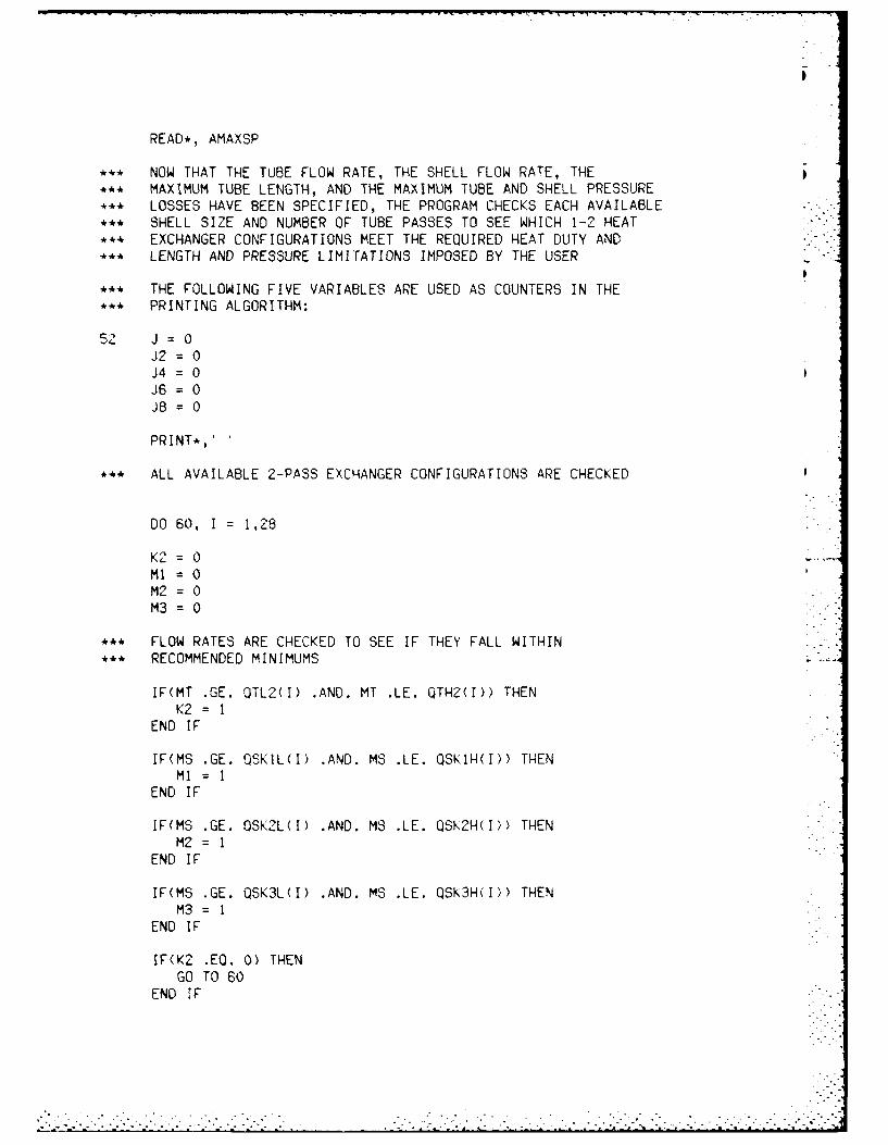
READ*, AMAXSP
*** NOW THAT THE TUBE FLOW RATE, THE SHELL FLOW RATE, THE*** MAXIMUM TUBE LENGTH, AND THE MAXIMUM TUBE AND SHELL PRESSURE*** LOSSES HAVE BEEN SPECIFIED, THE PROGRAM CHECKS EACH AVAILABLE*** SHELL SIZE AND NUMBER OF TUBE PASSES TO SEE WHICH 1-2 HEAT*** EXCHANGER CONFIGURATIONS MEET THE REQUIRED HEAT DUTY AND*** LENGTH AND PRESSURE LIMITATIONS IMPOSED BY THE USER
*** THE FOLLOWING FIVE VARIABLES ARE USED AS COUNTERS IN THE*** PRINTING ALGORITHM:
52 J=O0
J2 - 0J4 =0J6 = 0J8 = 0
PRINT*,'
*** ALL AVAILABLE 2-PASS EXCHANGER CONFIGURATIONS ARE CHECKED
DO 60, I = 1,28
K2 = 0MI = 0M2 = 0M3 = 0
*** FLOW RATES ARE CHECKED TO SEE IF THEY FALL WITHIN*** RECOMMENDED MINIMUMS
IF(MT .GE. QTL2(I) ,AND. MT .LE. QTH2(I)) THENK2 = I
END IF
IF(MS .GE. QSKIL(I) .AND. MS .LE. QSKlH(I)) THENMI = I
END IF
IF(MS .GE. 0SK2L(1) .AND. MS .LE. QSK2H(I)) THENM2 = I
END IF
IF(MS .GE. QSK3L(I) .AND. MS .LE. QSK3H(I)) THENM3 I
END IF
IF(K2 .EQ. 0) THENGO TO 60
END IF

WRITE(*,604) PICKS*DSI(N)604 FORMAT (' ',F6.2, INCHES')
PRINT*,''WRITE(*,605) L
605 FORMAT ('EXCHANGER TUBE LENGTH: ', F8.3, ' FEET')PRINT*,WRITE(*,606) PLTTOT
606 FORMAT ('TUBE-SIDE PRESSURE LOSS: ',F6.2,$ POUNDS PER SQUARE INCH')PRINT*,''WRITE(*,607) PLSTOT
607 FORMAT ('SHELL-SIDE PRESSURE LOSS: ',F6.2,$ ' POUNDS PER SQUARE INCH')PRINT*,'WRITE(*,608) Z
608 FORMAT ('ESTIMATED CAPITAL COST: $ ',F9.2)PRINT*,'
*** THESE VALUES ARE PRINTED TO SEE HOW CLOSE THE COMPUTED*** VALUE OF THE OVERALL HEAT TRANSFER COEFFICIENT COMES*** TO THE AVERAGE VALUE FOUND IN THE LITERATURE
PRINT*,'U = , UPRINT*,UCALC = ', UCALC
PRINT*,'PRINT+,'DO YOU WANT TO TRY A DIFFERENT HEAT EXCHANGER'PRINT*,'CONFIGURATION ? TYPE Y FOR YES AND N FOR NO.'PRINT*,'READ (5,101) ACALC
101 FORMAT (IAl)
IF(ACALC .EQ. 'N') THENGO TO 700
END IF
GO TO 71
700 PRINT*,,'PRINT*,'DO YOU WANT TO CHANGE ANY OF THE INPUT PARAMETERS'PRINT*,TO THIS PROBLEM " TYPE Y FOR YES AND N FOR NO'PRINT*,'
READ (5,101) AGAIN
!F (AGAIN .EQ. 'Y') THEN
PRINT*.'PRINT*,'DO YOU WANT TO CHANGE THE TUBING SIZE ?'PRINT*,'
READ (5,101) ATJBE
IF (ATUBE .EQ. 'Y') THEN
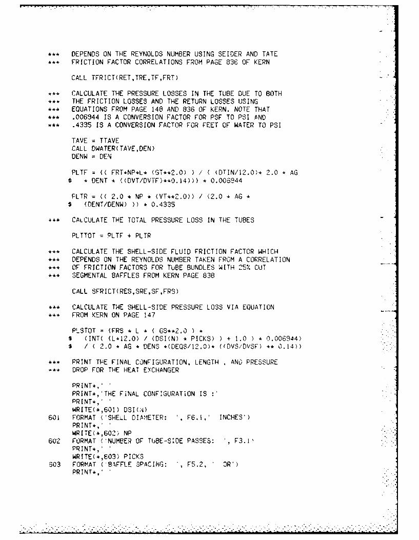
*** DEPENDS ON THE REYNOLDS NUMBER USING SEIDER AND TATE
*** FRICTION FACTOR CORRELATIONS FROM PAGE 836 OF KERN
CALL TFRICT(RET,TRE,TF,FRT)
*.* CALCULATE THE PRESSURE LOSSES IN THE TUBE DUE TO BOTH*** THE FRICTION LOSSES AND THE RETURN LOSSES USING.* EQUATIONS FROM PAGE 148 AND 836 OF KERN. NOTE THAT*** .006944 IS A CONVERSION FACTOR FOR PSF TO PSI AND*** .4335 15 A CONVERSION FACTOR FOR FEET OF WATER TO PSI
TAVE = TTAVECALL DWATER(TAVE,DEN)DENW = DEN
PLTF = (( FRT*NP*L* (GT**2.0)) / ( DTIN/12.0)* 2.0 * AG$ * DENT * ((DVT/DVTF)**0.14))) * 0.006944
FLTR = (( 2.0 * NP * (VT**2.0)) / (2.0 * AG *$ (DENT/DENW))) * 0.4335
.*. CALCULATE THE TOTAL PRESSURE LOSS IN THE TUBES
PLTTOT = PLTF + PLTR
** CALCULATE THE SHELL-SIDE FLUID FRICTION FACTOR WHICH,4, DEPENDS ON THE REYNOLDS NUMBER TAKEN FROM A CORRELATION.** OF FRICTION FACTORS FOR TUBE BUNDLES WITH 25% CUT*** SEGMENTAL BAFFLES FROM KERN PAGE 838
CALL SFRICT(RES,SRE,SF,FRS)
... CALCULATE THE SHELL-SIDE PRESSURE LOSS VIA EQUATION,,4 FROM KERN ON PAGE 147
PLSTOT : (FRS * L * ( GS**2.O ) *$ (INT( (L,12.0) / (DSI(N) * PICKS) ) + 1.0 ) * 0.006944)$ I ( 2.0 * AG * DENS *(DEQS/12.0) 4 ((DVS/DVSF) ** 0.14))
.,, PRINT THE FINAL CONFIGURATION, LENGTH AND PRESSURE*.* DROP FOR THE HEAT EXCHANGER
PRINT*,'PRINT*,'THE FINAL CONFIGURATION ISPRINT*,'WRITE(*,601) DSI(N)
601 FORMAT ('SHELL DIAMETER: , F6.1,' INCHES')PRINT*,'WRITE(*,602. NP
602 FORMAT ('NUMBER OF TUBE-SIDE PASSES: ', F3.1.PRINT*,'WRITE(,,603) PICKS
S03 FORMAT ('BAFFLE 3PACING: , F5.2, OR')PRINT*,'

* USING THE CALCULATED VALUE OF THE OVERALL HEAT TRANSFER
** COEFFICIENT, CALCULATE THE REQUIRED HEAT TRANSFER AREA.
ACORR =(NTU * CMIN)/ / UCALC
** USING THE CORRECT VALUE OF REQUIRED HEAT TRANSFER AREA,** CALCULATE THE LENGTH OF TUBING OF THE DESIRED HEAT** EXCHANGER CONFIGURATION.
IF (PICKP .EQ. 2.0) THENL = ACORR / AL2(N)
END IF
IF (PICKP .EQ. 4.0) THENL = ACORR / AL4(N)
END IF
IF (PICKP .EQ. 6.0) THENL = ACORR / ALS(N)
END IF
IF (PICKP .EQ. 8.0) THENL = ACORR /ALS(N)
END IF
NP = PICKPAG = 32.1740
**CALCULATE THE ESTIMATED COST OF THE HEAT EXCHANGER DES-IGN** USING EQUATIONS FOUND IN THE BOOK -EFFICIENCY AND COSTING.* BY GAGGIOLI ON PAGE 232
IF (PICKP .EQ. 2.0) THENZ = CF * 1150.0 *((DSI(N)/12.0) **1.05) *(L **0.3)
$ ((TPH/12.0) *40.75) *(NT2(N) **0.975)
END IF'
IF (PICKP .EQ. 4.0) THENZ = CF * 1150.0 *((DSI(N)/12.0) **1.05) *(L ~*0.3)*
$ ((TPH/12.0) **0.75) *(NT4(N) **0.375)
END IF
IF (PICKP .EQ. 6.0) THENZ = CF * 1150.0 *((DSI(N)/12.0) **1.05) *(L **0.3) *
$ ((TPH/'2.0) **0.75) * (NT6(N) **0.375)
END IF
IF (PICKP .EQ. 8.0) THENZ =CF * 1150.0 *((DCSI(N)/12.0) 4*1.05) * 'L 4*0.3)
$ ((TPH/12.0) **0.75) * (NTS(N) **0.975)
END IF
** CALCULATE THE TUBE-SIDE" FLUID FRICTION FACTOR 4HICH
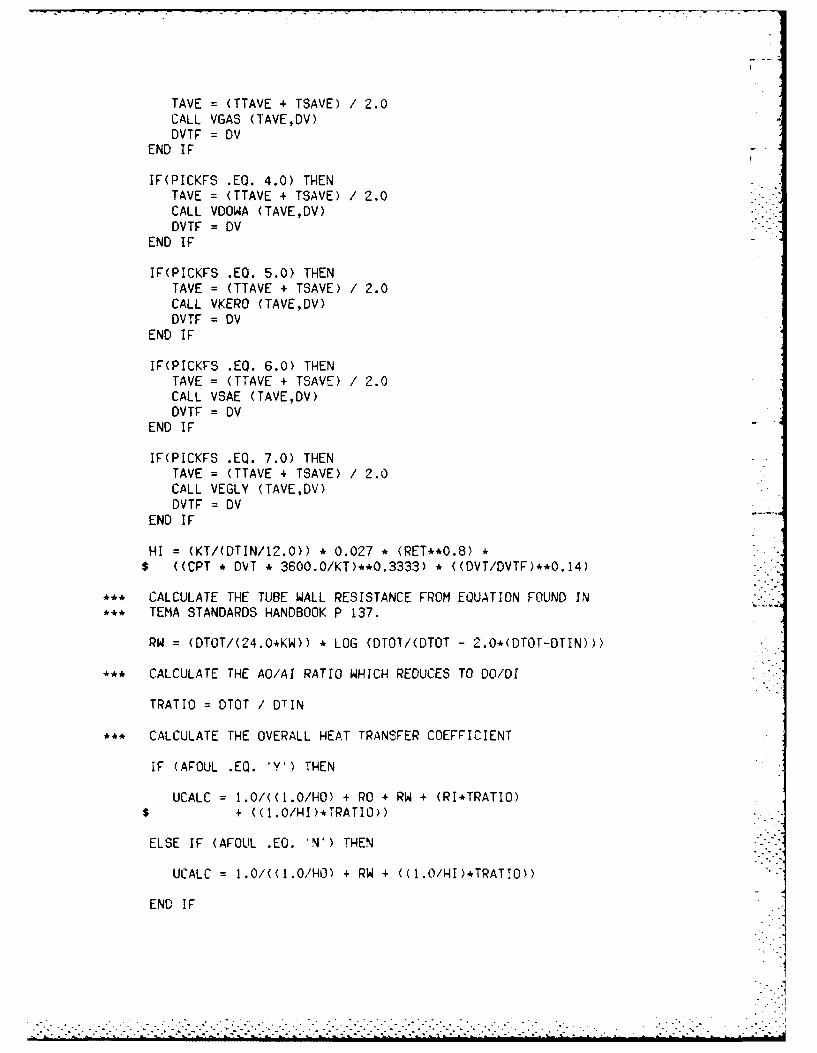
TAVE =(TTAVE + TSAVE) /2.0CALL VGAS (T'AVE,DV)DVTF =DV
END IF
IF(PICKFS .EQ. 4.0) THENTAVE = (TTAVE + TSAVE) /2.0CALL VOOWA (TAVE,DV)DVTF =DV
END IF
IF(PICKFS .EQ. 5.0) THENTAVE = (TTAVE + TSAVE) /2.0CALL VKERO (TAVE,DV)DVTF = DV
END IF
IF(PICKFS .EQ. 6.0) THENTAVE = (TTAVE + TSAVE) /2.0CALL VSAE (TAVE,DV)DVTF = DV
END IF
IF(PICKFS .EQ. 7.0) THENTAVE = (TTAVE + TSAVE) /2.0CALL VEGLY (TAVE,DV)DVTF =DV
END IF
HI = (KT/(DTIN/12e.0)) *0.027 * (RET**0.8)$ ((CPT *DVT *3600.0/KT)**0.3333) *((DVT/DVTF)**0.14)
*. CALCULATE THE TUBE WALL RESISTANCE FROM EQUATION FOUND IN** TEMA STANDARDS HANDBOOK P 137.
RW =(DTOT/(24.0*KW)) LOG (DTOT/(DTOT -2.0*(DTOT-DTIN)))
** CALCULATE THE AO/AI RATIO WHICH REDUCES TO DO/DI
TRATIO = OTOT / DTIN
** CALCULATE THE OVERALL HEAT TRANSFER COEFFICIENT
IF (AFOUL .EQ. 'Y') THEN
UCALC 1 .0/((1.0/HO) + RO + RW + (RI*TRATIO)$ + U1I.0/HI)*TRATIO))
ELSE IF (AFOUL .EQ. 'N') THEN
UCALC 1.0/((l.0/HO) +RW + <((1./I)*TRATlO))
END IF

TAVE =(TTAVE + TSAVE) /2.0CALL VMETH (TAVE,DV)DVSF = DV
END IF
iF\'PICKFS .EQ. 3.0) THENTAVE = (TTAVE + TSAVE) /2.0CALL VGAS (TAVE,DV)DVSF = DV
END IF
IF(PICKFS .EQ. 4.0) THENTAVE = (TTAVE + TSAVE) /2.0CALL VOOWA (TAVE,DV)DVSF = DV
END IF
IF(PICKFS .EQ. 5.0) THENTAVE = (TTAVE + TSAVE) 2.0CALL VKERO (TAVE,DV)DVSF = DV
END IF
IF(PICKFS .EQ. 6.0) THENTAVE = (TTAVE + TSAVE) /2.0CALL VSAE (TAVE,DV)DVSF = DV
END IF
IF(PICKFS .EQ. 7.0) THENTAVE = (TTAVE + TSAVE) /2.0CALL VEGLY (TAVE,DV)DVSF = DV
END IF
HO = (KS/(DEQS/12^-.0)) * 0.36 *(RES**0.55)$((CPS * DVS *3600.0/KS)**0.3333) * ((DVS/IDVSF)**0.14)
** FROM 'HEAT EXCHANGE TECHNOLOGY' BY STRUTHER3 WELLS** CORPORATION P 1 36
IF(PICKFS .EQ. 1.0) THENTAVE = (TTAVE + TSAVE) /2.0CALL VWATER (TAVE,DV)DVTF = DV
END IF
IF(PICKFS .EQ. 2.0)) THENTAVE = (TTAVE + TSAVE) /2.0CALL VMETH (TAVE,0V)DVTF = Ov
END IF
IR(P!CKFS .EQ. 3.0) THEN

IF (PICKP .EQ. 8.0) THENVT = (C*MT) / (ATIN * (NT8(N)/8.0)
END IF
•** CALCULATE THE EQUIVALENT DIAMETER OF THE FLUID CONDUIT•** CROSSING THE TUBES USING EQUATIONS FROM KERN IN HIS BOOK*** PROCESS HEAT TRANSFER ON PAGE 139. THE EQUATION IS FOR A* ** TRIANGULAR PITCH ARRANGEMENT ONLY. UNITS ARE IN INCHES.
DEQS=(4.0*((.5*TPH)*(.86*TPH)-((.5*PI*(DTOT**2.))/4.0)))$ /(.5*DTOT)
• ** THE MASS VELOCITY OF THE SHELL FLUID IS CALCULATED. UNITS• ** ARE LB/SEC-SQUARE FEET
GS = VS * DENS
•** THE REYNOLDS NUMBER OF THE SHELL FLUID 1i CALCULATED
RES : ( (DEOS / 12.0) * GS ) / DVS
•** THE MASS VELOCITY OF THE TUBE FLUID IS CALCULATED. UNITS•** ARE LB/SEC-SQUARE FEET
GT = VT * DENT
• ** THE REYNOLDS NUMBER OF THE TUBE FLUID IS CALCULATED
RET = ( (DTIN / '2.0) * GT) / DVT
* ** NOW THAT THE CONFIGURATION HAS BEEN CHOSEN, CALCULATE THE** OVERALL U VALUE FOR THE HEAT EXCHANGER USING GENERALIZED
• ** CORRELATIONS FOUND IN THE REFERENCES.
**~ FROM TEMA PAGE 137, THE OVERALL HEAT TRANSFER COEFFICIENT** REQUIRES THE EVALUATION OF:•** HO : THE FILM COEFFICIENT OF THE FLUID OUTSIDE THE TUBES•** HI : THE FILM COEFFICIENT OF T8HE FLUID INSIDE THE TUBES•** RO : THE FOULING RESISTANCE ON THE OUTSIDE OF THE TUBES*** RI : THE FOULING RESISTANCE ON THE INSIDE OF THE TUBES•** RW : THE RESISTANCE OF THE TUBE WALL REFERRED TO THE
OUTSIDE SURFACE OF THE TUBE WALL• ** AO/Al : THE RATIO OF OUTSIDE TO INSIDE SURFACE OF TUBING
S*. FROM 'HEAT EXCHANGE TECHNOLOGY' BY STRUTHERS WELLSS** CORPORATION P 157
IF(PICKFS .EQ. 1.0) THENTAVE = (TTAVE + TSAVE) / 2.0CALL VWATER (TAVE,DV)DVSF = DV
END IF
IF(PICKFS .EQ. 2.0) THEN

*** IF THERE ARE AVAILABLE CONFIGURATIONS THAT MEET THE* DESIGN SPECIFICATIONS, THE USER IS ASKED FOR HIS*** CHOICE OF CONFIGURATIONS THAT A FINAL OUTPUT IS DESIRED
70 PRINT*,'PRINT*,'PRINT*, THE NEXT THREE QUESTIONS PERTAIN TO YOUR CHOICE'PRINT*,'OF THE ABOVE LISTED HEAT EXCHANGERPRINT*,'CONFIGURATIONS. REMEMBER ONLY THESE LISTED'PRINT*,'CONFIGURATIONS WILL MEET THE REQUIREMENTS YOU'PRINT*,'HAVE INPUT INTO THE PROGRAM'PRINT*,'
71 PRINT*,'WHAT SHELL DIAMETER DO YOU CHOOSE ? TYPE 12.0,'PRINT*,'14.0, 28.0 etc.'PRINT*,READ*,PICKDPRINT*,'PRINT*,'WHAT NUMBER OF TUBE PASSES DO YOU CHOOSE ? TYPE'PRINT*,'2.0, 4.0, 6.0, OR 8.0'PRINT*,'READ*,PICKPPRINT*,'PRINT*,'WHAT SHELL BAFFLE SPACING DO YOU CHOOSE ? TYPE'PRINT*,'0.2, 0.45, OR 1.0'PRINT*,'READ*,PICKS
N = INT( (PICKD/2.0) - 2.0
*** ONCE THE HEAT EXCHANGER CONFIGURATION HAS BEEN SELECTED, THE*** PROGRAM CAN NOW CALCULATE THE ACTUAL SHELL AND TUBE FLUID*** VELOCITIES. NOTE THAT C IS A CONVERSION FACTOR TO GET VELOCITY*** IN FT/SEC BY INPUTTING A FLOW RATE OF GALLONS PER MINUTE AND*** HAVING AREA IN INCHES.
C = .3208342
ASC = (DSIU(N)/TPH) * TC * (PICKS * DSI(N))
VS : C * MS/ASC
IF (PICKP .EQ. 2.0) THENVT = iC*MT) / (ATIN * (NT2(N)/2.0"
END IF
IF (PICKP .EQ. 4.0 THENVT = (C*MT) / (ATIN * (NT4(N)/4.0)
END IF
IF (PICKP .EQ. 6.0) THENVT (C*MT) / (ATIN * (NT6(N)/6.0) )
END !F
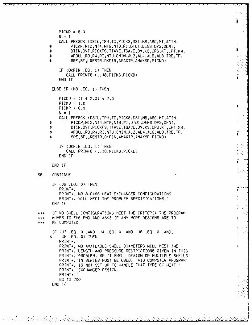
PICKP = 8.0N=ICALL PRESCK (DSIU,TPH,TC,PICKS,DSI,MS,ASC,MT,ATIN,
$ PICKP,NT2,NT4,NT6,NT8,PIDTOT,DENS,DVS,DENT,$ DTIN,DVTPICKFS,TTAVE,TSAVE,DV,KS,CPS,KT,CPT,KW,$ AFOUL,RO,RW,RI,NTU,CMIN,AL2,AL4,AL6,AL8,TRE,TF,$ SRE,SF,LRESTR,OKFIN,AMAXTP,AMAXSP,PICKD)
IF (OKFIN .EQ. 1) THENCALL PRINT8 (J,J8,PICKS,PICKD)
END IF
ELSE IF (M3 .EQ. 1) THEN
PICKD = (I + 2.0) * 2.0PICKS = 1.0PICKP = 8.0N = ICALL PRESCK (DSIU,TPH,TC,PICKS,DSI,MS,ASC,MTATIN,
$ PICKP,NT2,NT4,NT6,NT8,PI,DTOT,DENS,DVS,DENT,$ DTIN,DVT,PICKFS,TTAVE,TSAVE,DV,KS,CPS,KT,CPT,KW,$ AFOUL,RO,RW,RI,NTU,CMIN,AL2,AL4,AL6,AL8,TRE,TF,$ SRE,SF,LRESTR,OKFIN,AMAXTP,AMAXSP,PICKD)
IF (OKFIN .EQ. 1) THENCALL PRINT8 (JJ8,PICKS,PICKD)
END IF
END IF
66 CONTINUE
IF (J8 .EQ. 0) THENPRINT*,'PRINT*,'NO 8-PASS HEAT EXCHANGER CONFIGURATIONS'PRINT*,'WILL MEET THE PROBLEM SPECIFICATIONS.'
END IF
• IF NO SHELL CONFIGURATIONS MEET THE CRITERIA THE PROGRAM** MOVES TO THE END AND ASKS IF ANY MORE DESIGNS ARE TO• BE COMPUTED
IF (J .EQ. 0 .AND. J4 .EQ. 0 .AND. J6 .EQ. 0 .AND.Jb .EQ. 0) THEN
PRINT*,'PRINT*,'NO AVAILABLE SHELL DIAMETERS WILL MEET THE '
PRINT*,'LENGTH AND PRESSURE RESTRICTIONS GIVEN IN THIS'PRINT*,'PROBLEM. SPLIT SHELL DESIGN OR MULTIPLE SHELLS'PRINT*,'IN SERIES MUST BE USED. 'HIS COMPUTER PROGRAM'PRINT*,'IS NOT SET UP TO HANDLE THAT TYPE OF HEATPRINT*, EXCHANGER DESIGN.'PRINT*,'GO TO 700
END IF-

M1 = 0M2 = oM3 = 0
*** FLOW RATES ARE CHECKED TO SEE IF THEY FALL WITHIN*** RECOMMENDED MINIMUMS
IF(MT .GE. QTL8(I) .AND. MT .LE. QTHS(I)) THENK8 = I
END IF
IF(MS .GE. QSKIL(I) .AND. MS .LE. QSKlH(1)) THENMI = I
END IF
IF(MS .GE. QSK2L(I) .AND. MS .LE. QSK2H(I)) THENM2 -
END IF
IF(MS .GE. QSK3L(I) .AND. MS .LE. QSK3H(I)) THENM3 = I
END IF
IF(K8 .EQ. 0) THENGO TO 66
END IF
IF(M1 .EQ. 0 .AND. M2 .EQ. 0 .AND. M3 .EQ. 0) THENGO TO 66
END IF
*** A PRESSURE CHECK AND LENGTH CHECK SUBROUTINE IS CALLED IF*** THE SHELL DIAMETER MEETS THE INITIAL FLOW RATE CRITERIA
IF (Ml .EQ. 1) THEN
PICKD = (I + 2.0) * 2.0PICKS = 0.2PICKP = 8.0N=ICALl. PRESCK (DSIU,TPH,TCPICKS,DSI,MS,ASC,MT,ATIN,
$ PICKP,NT2,NT4,NT6,NT8.PI,DTOT,DENS,DVS.DENT,$ DTIN,DVT,PICKFS,TTAVE,TSAVE,DVKS,CPS,KT,CPT,KW,$ AFOUL,RO,RWRI,NTU,CMIN,AL2,AL4,AL6,AL8,TRE,TF,$ SRE,SF,LRESTR,OKFIN.AMAXTP,AMAXSP,PICKD)
IF (OKFIN .EQ. 1, THENCALL PRINT8 (J,J8,PICKS,PICKD)
END IF
ELSE IF (M2 EQ. 1) THEN
PICKD = (I + 2.0) * 2.0PICKS = 0.45
. . ..
-. . . . . . . . . .. - ... . . . . . . . . . . . . . .."" "" " " . . . . . . . . .."" ' '' " "

IF (OKFIN .EQ. 1) THENCALL PRINT6 (J,J6,PICKS,PICKD)
END IF
ELSE IF (M2 .EQ. 1) THEN
PICKD =(I + 2.0) *2.0
PICKS = 0.45PICKP = 6.0N = ICALL PRESCK (DSIU,TPH-,TC,PICKS,DSI,MS,ASC,MT,ATIN.
$ PICKP,NT2,NT4,NT6,NT8,PI,DTOT,OENSDVS,DENT,$ DTIN,DVT,PICKFS,TTAVE,TSAVE,DV,KS,CPS,KT,CPT,KW,$ AFOUL,RO,RW,RI,NTU,CMIN,AL2,AL4,AL6,AL8,TRE,TF,
$ SRE,SF,LRESTR,OKFIN,AMAXTP,AMAXSP,PICKD)
IF (OKFIN .EQ. 1) THENCALL PRINT6 (J,J6,PICKS,PICKD)
END IF
ELSE IF (M3 .EQ. 1) THEN
PICKD = (1 2.0) *2.0
PICKS = 1.0PICKP = 6.0N =ICALL PRESCK (DSIU,TPH,TC,PICKS,DSI,MS,ASC,MT,ATIN,
$ PICKP,NT2,NT4,NT6,NT8,PI,DTOT,DENS,DVS,DENT,$ DTIN,DVT,PICKFS,TTAVE,TSAVE,DV,KS,CPS,KT,CPT,KW,$ AFOUL,R0,RW,RI,NTU,CMIN,AL2,AL4,AL6,AL8,TRE,TF,$ SRE.,SF.,LRESTR,OKFIN,AMAXTP,AMAXSP,PICKD)
IF (OKFIN .EQ. 1) THENCALL PRINT6 (J,J6,PICKS.,PICKD)
END IF
END IF
64 CONTINUE
IF (J6 .EO. 0) THENPRINT*,'PRINT*,'NO 6-PASS HEAT EXCHANGER CONFIGURATIONS'PRINT*,'WILL MEET THE PROBLEM SPECIFICATIONS.'
END IF
PRINT*,'
** ALL AVAILABLE 8-PASS CONFIGURATIONS ARE CHECKED
65 DO 66, I 1 ,28
Q3 0

END IF
PRINT*,'
• ** ALL AVAILABLE 6-PASS CONFIGURATIONS ARE CHECKED
63 DO 64, I 1,28
K6 = 0MI = 0M2 = 0M3 = 0
• ** FLOW RATES ARE CHECKED TO SEE IF THEY FALL WITHIN• ** RECOMMENDED MINIMUMS
IF(MT GE. QTL6(I) .AND. MT .LE. QTH6(1)) THENK6 = 1
END IF
IF(MS .GE. QSKIL(1) .AND. MS .LE. QSKIH(I') THENMI I 1
END IF
IF(MS .GE. QSK2L(I) .AND. MS .LE. QSK2H(I)) THENM2 := 1 -. .
END IF
IF(MS .GE. QSK3L(i) .AND. MS .LE. QSK3H(I)) THENM3 I 1
END IF
IF(K6 .EQ. 0) THENGO TO 64
END IF
IF(M1 .EQ. 0 .AND. M2 .EQ. 0 ,AND. M3 .EQ. 0) THENGO TO 64
END IF
** A PRESSURE CHECK AND LENGTH CHECK SUBROUTINE 13 CALLED IFS*.* THE SHELL DIAMETER MEETS THE INITIAL FLOW RATE CRITERIA
IF (Ml .EQ. 1) THEN
PICKD = (I + 2.0) * 2.0PICKS = 0.2PICKP = 6.0N = ICALL PRESCK (DSIU,TPH,TC,PICKS,DSI,MS,ASC,MT,ATIN.
$ PICKP,NT2,NT4,NT6,NT8,PIDTOT,DENS,DVS,DENT,$ DTIN,DVT,PICKFS,TTAVE,TSAVE,DV,KS,CPS,KT,CPT,KW,$ AFOUL,RORW,RI,NTUCMIN,AL2,AL4,AL6.AL8,TRE,TF,
SRE,SF,LRESTR,OKFIN,AMAXTP,AMAXSP,PICKD)
,s L..4 .-- .... . .

PICKO = (I + 2.0) *2.0
PICKS = 0.2PICKP = 4.0N =I
dCALL PRESCK (DSIU,TPR,TC,PICKS,DSI,MS,ASC,MT,ATIN,$ PICKP,NT2,NT4.NT6,NT8,PI,DTOT,DENS,DVS,DENT,$ DTIN,DVT,PICKFSTTAVE,TSAVE,DV,KS,CPS,KT,CPT,KW,$ AFOUL,R0,RW,R1,NTU,CMIN,AL2,AL4,AL6,AL8,TRE,TF,$ SRE,SF,LRESTR,OKFIN,AMAXTP,AMAXSP,PICKD)
IF (OKFIN .EQ. 1) THENCALL PRINT4 (J,J4,PICKS,PICKD)
END IF
ELSE IF (M2 .EQ. 1) THEN
PICKD =(I + 2.0) * 2.0PICKS =0.45PICKP =4.0N =ICALL PRESCK (DSIU,TPH,TCPICKS,DSI,M8,ASC,MTATIN,
$ PICKP,NT2,NT4,NT6,NT8,PI,DTOT,DENS,DVS,DENT,$ DTIN,DVT,PICKFS,TTAVETSAVE,DVqK8,CPS,KT,CPT,KW,$ AFOUL,R0,RW,RI,NrU,CMIN,AL2-,AL4,AL6,AL8,TRE,rF,$ SRE,SF,LRESTR,OKFIN,AMAXTP,AMAXSP,PICKD)
IF (OKFIN .EQ. 1) THENCALL PRINT4 (J,J4,PICKS,PICKD)
END IF
ELSE IF (M3 .EQ. 1) THEN
PICKD (I + 2'-.0) * 2.0PICKS =1.0PICKP =4.0N = ICALL PRESCK (DSIU,TPH,TC,PICKS,DSI,MSASC,MT,ATIN.
$ PICKP,NT2,NT4,NT6,NT6,PI,DTOT,DENS,DVS,DENT,$ DTIN,DVT,PICKFS,TTAVE,TSAVE,DV,KS,CPS,KT,,CPTKW,$ AFOUL,R0,RW,R1,NTU,CMIN,AL2-,AL4.AL6,AL8,TRE,TF,$ SRE,SF,LRESTR,OKFIN,AMAXTP,AMAXSP,PICKD)
IF (OKFIN .EQ. 1) THENCALL PRINT4 (JJ4,PICKS,PICKD)
END IF
END IF
62 CONTINUE
IF (J4 .EQ. 0) THENJPRINT*,'PRINT*C'NO 4-PASS HEAT E,\CHANgGER CONFIG-UATIONSPRINT*,.IJILL MEET THE PROBLEM1 SPECIFICATIONS.'
END IF
60 CONTINUE
IF (J2 .EQ. 0) THENPRINT*,PRINT*, 'NO 2-PASS HEAT EXCHANGER CONFIGURATIONS'PRINT*,'WILL MEET THE PROBLEM SPECIFICATIONS.'
END IF
PRINT*,'
k** ALL AVAILABLE 4-PASS CONFIGURATIONS ARE CHECKED
61 DO 62, 1 = 1,28
K4 =0MI = 0M2 =0M3 =0
** FLOW RATES ARE CHECKED TO SEE IF THEY FALL WITHIN** RECOMMENDED MINIMUMS
IF(MT .GE. QTL4(I) .AND. MT .LE. QTH4(I)) THENK4 = 1
END IF
IF(MS .GE. QSKIL(I) .AND. MS .LE. QSKIH(I)) THENMI = 1
END IF
IF(MS .GE. QSK2L(I) .AND. MS .LE. QSK2H(!)) THENM2 = I
END IF
IF(MS .GE. QSK3L(I) .AND. MS .LE. QSK3H(I)) THENM3 = 1
END IF
IF(K4 .EQ. 0) THENGO TO 62
END IF
IF(M. .EQ. 0 .AN[D. M2 .EQ. 0 .AND. M3 .EQ. 0) THENGO TO 62
END IF
** A PRESSURE CHECK AND LENGTH CHECK SUBROUTINE IS CALLED IF** THE SHELL DIAMETER MEETS THE INITIAL FLOW RATE CRITERIA
ic (Ml .EQ. 1) THEN

IF(M1 .EQ. 0 .AND. M2 .EQ. 0 .AND. M3 .Z0. 0) THENGO TO 60
END IF
** A PRESSURE CHECK AND LENGTH CHECK SUBROUTINE IS CALLED IF*. THE SHELL DIAMETER MEETS THE INITIAL FLOW RATE CRITERIA
IF (Ml .EQ. 1) THEN
PICKD = (I + 2.0) * 2.0PICKS = 0.2PICKP = 2.0N = ICALL PRESCK (DSIU,TPH,TC,PICKS,DSI,MS,ASC,MT,ATIN,
$ PICKP,NT2,NT4,NT6,NTS,PI,DTOT.DENS,DVS,DENT,$ DTIN,DVT,PICKFS,TTAVEqTSAVE,DVqKSqCPS,KT,CPT.KW,$ AFOUL,RO,RW,RI,NTU,CMIN,AL2L>,AL4,AL6,ALS,TRE,TF,$ SRE,SF,LRESTR,OKFIN,AMAXTP,AMAXSP,PICKD)
IF (OKFIN .EQ. 1) THENCALL PRINT2 (J,J2,PICKS,PICKD)
END IF
ELSE IF (M2 .EQ. 1) THEN
PICKD = (I + 2.0) * 2.0PICKS = 0.45PICKP = 2.0N= ICALL PRESOK (DSVIU,TPH,TC,PICKS,DSI,MS,ASC,MT,ATIN,
$ PICKP,NT2.NT4,NT6,NT8,PI,DTOT,DENS,DVS,DENT.,$ DTIN,DVT,PICKFS,TTAVE,TSAVE,DV,KS,CPS,KT,CPT,KW,$ AFOUL,RO,RW,RI,NTU,CNIN,AL-,AL4,ALG,ALG,TRE,TF-,$ SRE,SF,LRESTR ,OKFIN,AMAXTP.AMAXSP ,PICKD)
IF (OKFIN .EQ. 1) THENCALL PRINT2 (J,J2,PICKS,PICKD)
END IF
ELSE IF (M3 .EQ. 1) THEN
PICKD = (I + 2.0) * 12.0P ICKS3 = 1. 0PICKP = 2.0N = ICALL PRESCK (DSIU,TPH,TC,PICKS,DSI,MS,ASC,MT,ATINl,
$ PlICKP,NT2,NT4,NT6,NTS,PI.DTOT,DENS,DVSDENT,$ DT IN,DVT,PICKFS,TTAVE,TSAVE,DV,KS.CPS,KT,CPT,KW,$ AFOUL,RO,RW,RI,NTU,OMIN,AL2,AL4qAMLS,ALS,TRE,TF,$ SRE,SF,LRESTR,OKFIN,AMAXTP,AMAXS-P,FICKD)
IF (OKFIN .EQ. 1) THENCALL PRINT2 (J,J2,PICKS,PICKD.
END IF

GO TO 4END IF
PRINT*,702 PRINT*,'DO YOU WANT TO CHANGE THE TUBING MATERIAL ?,
PRINT*,
READ (5,101) AMATE
IF (AMATE .EQ. 'Y') THENGO TO 703
END IF
PRINT*,704 PRINT*,'DO YOU WANT TO CHANGE THE TUBE FLUID CHOICE ?'
PRINT*,'
READ (5,101) ATFLU
IF (ATFLU .EQ. 'Y') THENGO TO 705
END IF
PRINT*,'706 PRINT*,.'DO YOU WANT TO CHANGE THE SHELL FLUID CHOICE ?'
PRINT*,'
READ (5,101) ASFLU
IF (ASFLU .EQ. 'Y') THENGO TO 707
END IF
PRINT*,'708 PRINT*,'DO YOU WANT TO CHANGE THE TUBE FLUID TEMPS ?'
PRINT*,'
READ (5,101) ATTEM
IF (ATTEM .EQ. 'Y') THENGO TO 709
END IF
PRINT*,'7'0 PRINT*,'DO YOU WANT TO CHANGE THE TUBE FLUID FLOW RATE "
PRINT*,''
READ (5,101) ATGPM
iF (ATGPM .ZO. 'Y') THENGO TO III
END IF
PRINT*,'
712 PRINT4,DO YOU WANT TO CHANGE THE SHELL FLUID TEMP ?
PRINT*,'
READ (5,101) A,-TEM
IF (ASTEM .EQ. 'Y') THENGO TO 713
END IF
PRINT*,714 PRINT*,'DO YOU WANT TO CHANGE THE SHELl FLUID FLOW RATE ?'
PRINT*,'
READ (5,10!) ASGPM
IF (ASGPM .EQ. 'Y') THENGO TO 719
END IF
PRINT*,'716 PRINT*,'DI YOU WANT TO CHANGE THE DECISION ON WHETHER OR'
* PRINT*,'NOT A FOULING FACTOR IS U:SED ?
PRINT*,'
READ (5,101) AFFAC
PRINT*,'PRINT*,'DO YOU WANT TO CHANGE THE LENGTH RESTRICTION ?
PRINT*,'
READ (5,101) ALREST
PRINT*,PRINT*,'DO YOU WANT TO CHANGE THE MAXIMUM ALLOWABLE'PRINT*,'PRESSURE LOSSES ?'PRINT*,'
READ (5,101) APRES
GO TO 3
END IF
PRINT*,'800 PRINT*,'DO YOU WANT TO DO ANY OTHER HEAT EXCHANGER
PRINT*,'PROBLEMS ? TYPE Y FOR YES AND N FOR NO.'
READ (5,101) ACALC
IF (ACALC .EO. 'N') THENGO TO 999
END !F
IF (ACALC .EO. 'Y'l THEN
AGAIN = 'N'AFFAC='YALREST =Y
APRES = YGO TO 4
END IF
939 STOP'DONE'
END

APPENDIX C
FLUID PROPERTY SUBROUTINES (WATER ONLY)

I
SUBROUT I NE DWATER ( TAVE,DEN)*** THIS SUBROUTINE CALCULATES THE DENSITY OF WATER AT*** THE AVERAGE FLUID TEMPERATURE FOR TEMPERATURES*** FROM 32.0 DEF F TO 600 DEG F. UNITS ARE LBM/CUBIC FT
IF (TAVE .LE. 32.0) THENDEN = 62.4GO TO 100
END IF
IF (TAVE .LE. 50.0) THENDEN = 62.4GO TO 100
END IF
IF (TAVE .EQ. 100.0) THENDEN = 62.0GO TO 100
END IF
IF (TAVE .LT. 100.0) THENT = 50.0TI = 100.0D = 62.4DI = 62.0FRAC = (100.0 - TAVE) I (TI - T) • (D - DI)DEN =DI + FRACGO TO 100
END IF
IF (TAVE .EQ. 150.0) THENDEN = 61.2GO TO 100
END IF
IF (TAVE .LT. 150.0) THENT = 100.0Ti = 150.0D = 62.0Dl = 61.2FRAC = (150.0 - TAVE) / (TI - T) * (D - DI)DEN = D1 + FRACGO TO 100
END IF
IF (TAVE .EQ. 200.0) THENDEN = 60.1GO TO 100
END IF
IF (TAVE .LT. 200.0) THEN LT = 150.0TI : 200.0
-. . . - . .-... ., ...... .. .- . . .. ... ... ..-.. .. . .- , .. .:......,.,.:.:.:,..:....,,.,
- --... - .o . - -....... ... o . ............ . . . .. o. ......
D =61. 2DI 60.1FRAC =(200.0 -TAVE) /(Ti T) *(D -DI)
DEN =D1 + FRACGO TO 100
END IF
IF (TAVE .EQ. 250.0) THENDEN = 58.8GO TO 100
END IF
IF (TAVE .LT. 250.0) THENT = 200.0Ti = 250.0D = 60.1DI = 58.8FRAC =(250.0 - TAVE) /(Ti- T) *(D DI0)DEN = DI + FRACGO TO 100
END IF
IF (TAVE .EQ. 300.0) THENDEN = 57.3GO TO 100
END IF
IF (TAVE .LT. 300.0) THENT =250.0TI 300.0D 58.8Di= 57.3FRAC =(300.0 -TAVE) /(TI- T) *(D -DI)
DEN =Di +t FRACGO TO 100
END I F
IF (TAVE .EQ. 350.0) THENDEN = 55.6GO TO 100
END IF
IF (TAVE .LT. 350.0) THENT = 300.0T= 350.0
D = 57.3DI = 55.6FRAC =(350.0 - TAVE) /(Ti T) *(D -DO)
DEN =D1 + PRACGO TO 100
END IF
IF (TAVE .EQ. 400.0) THENDEN =53.6

GO TO 100END IF
IF (TAVE .LT. 400.0) THEN
T : 350.0TI = 400.0D = 55.6DI = 53.6FRAC = (400.0 - TAVE) / (TI - T) * (D - Dl)
DEN = DI + FRACGO TO 100
END IF
IF (TAVE .EQ. 450.0) THENDEN = 51.6GO TO 100
END IF
IF (TAVE .LT. 450.0) THENT = 400.0TI = 450.0D = 53.6Dl = 51.6FRAC (450.0 - TAVE) / (TI - T) • (D - DI)DEN = 0i + FRACGO TO 100
END IF
IF (TAVE .EQ. 500.0) THENDEN = 49.0GO TO 100
END IF
IF (TAVE .LT. 500.0) THENT = 450.0TI = 500.00 = 51.6DI = 49.0FRAC = (500.0 - TAVE) / (TI - T) * (D - DI)
DEN : Dl + FRACGO TO 100
END IF
IF (TAVE .EQ. 550.0) THENDEN = 45.9GO TO 100
END IF
IF (TAVE .LT. 550.0) THEN
T = 500.0TI = 550.0O = 49.0Di = 45.9FRAC (550.0 - TAVE) / (TI - T * (D - DI)
.. . . ...-...-...... .. .-.- -.-...-.. . . . . .- - -- .-: ........ ..-. ." •- -i ii.. . .... .i:.,Z:',-:L.. : "'_ - . .. .. - . -_. -. . .. . . . . . .. . . . ..

DEN =DI FRACGO TO 100
END IF
IF (TAVE .EQ. 600.0) THENDEN = 42.4GO TO 100
END IF
IF (TAVE .LT. 600.0) THENT =550.0Ti 600.0D 45.9DI 42.4FRAC =(600.0 - TAVE) /(Ti T) *(D -Dl)
DEN 01 + FRACGO TO 100
END IF
IF (TAVE .GT. 600.0) THENDEN = 42.4
END IF
100 RETURNEND
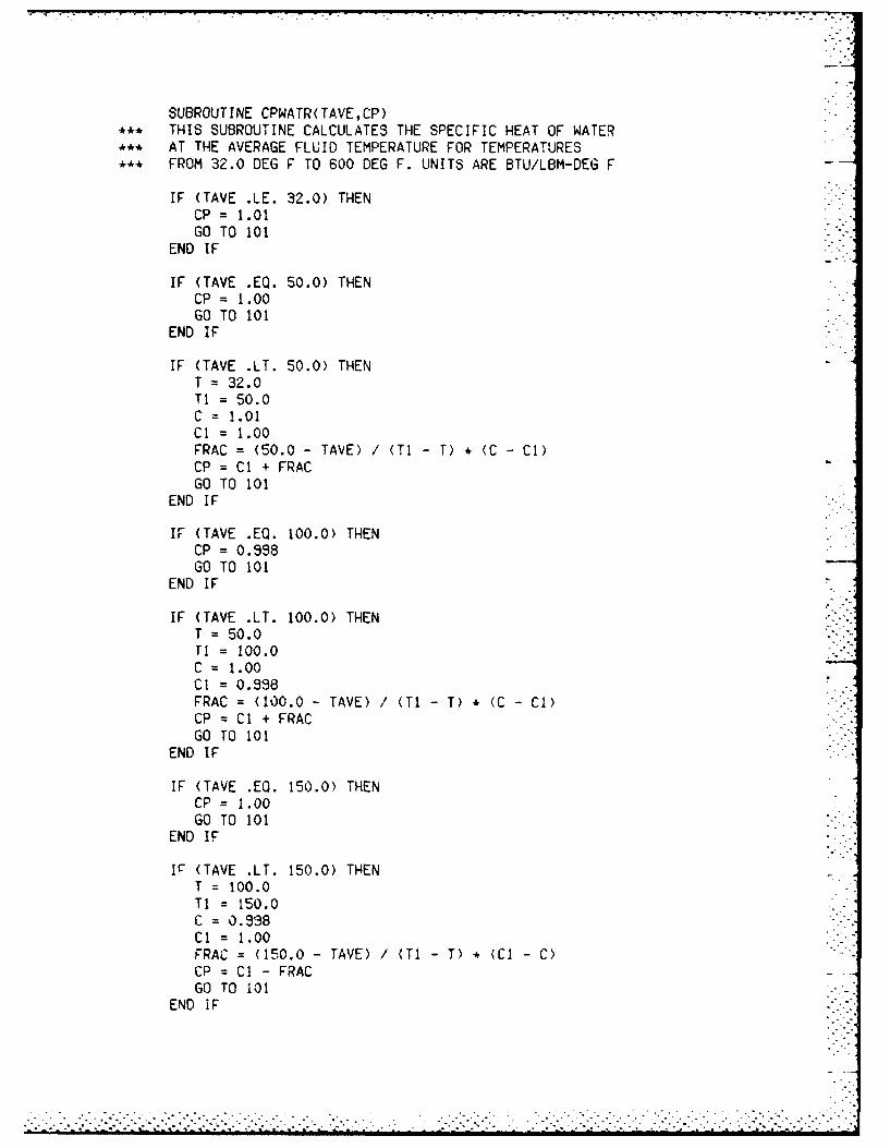
SUBROUTINE CPWATR( TAVE,CP)** THIS SUBROUTINE CALCULATES THE SPECIFIC HEAT OF WATER** AT THE AVERAGE FLUID TEMPERATURE FOR TEMPERATURES** FROM 32.0 DEG F TO 600 DEG F. UNITS ARE BTU/LBM-DEG F
IF (TAVE .LE. 32.0) THENCP = 1.01GO TO 101
END IF
IF (TAVE .EQ. 50.0) THENCP = 1.00GO TO 101
END IF
IF (TAVE .LT. 50.0) THENT =32.0Ti = 50.0C =1.01Cl = 1.00FRAC = (50.0 - TAVE) /(TI -T) *(C -Cl)
CP = Cl + FRACGO TO 101
END IF
IF (TAVE .EQ. 100.0) THENCP = 0.998GO TO 101
END IF
IF (TAVE .LT. 100.0) THENT = 50.0Ti = 100.0C =1.00Cl = 0.998FRAC =(100.0 -TAVE) I(Ti T) *(C -Cl)
CR = Cl + FRACGO TO 101
END IF
IF (TAVE .EO. 150.0) THENCP = 1.00GO TO 101
END IF
IF* (TAVE .LT. 150.0) THENT =100.0TI 150.0C =0.938Cl = 1.00FRAC = (150.0 -TAVE) /(TI- T) *(Cl -C)
CP = Cl - FRACGO TO 101
END IF
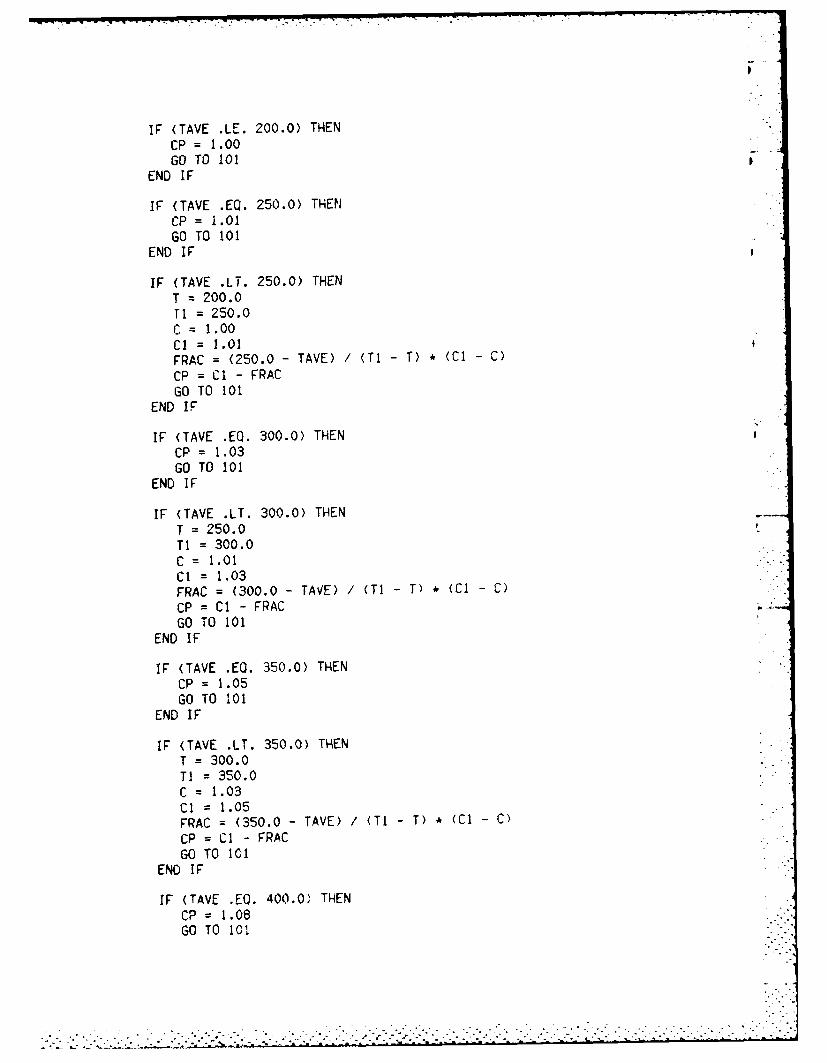
IF (TAVE .LE. 200.0) THENCP = 1.00GO TO 101
END IF
IF (TAVE .EQ. 250.0) THENCP = 1.01GO TO 101
END IF
IF (TAVE .LT. 250.0) THENT = 200.0Tl = 250.0C = 1.00Cl = 1.01FRAC = (250.0 - TAVE) / (TI - T) * (Cl - C)
CP = Cl - FRACGO TO 101
END IF
IF (TAVE .EQ. 300.0) THENCP = 1.03GO TO 101
END IF
IF (TAVE .LT. 300.0) THENT : 250.0Ti = 300.0C 1.01Cl = 1.03FRAC = (300.0 - TAME) / (TI - T) * (CI - C)
CP = Cl - FRACGO TO 101
END IF
IF (TAVE .EO. 350.0) THENCP = 1.05GO TO 101
END IF
IF (TAVE .LT. 350.0) THENT = 300.0TI = 350.0C = 1.03Cl = 1.05FRAC = (350.0 - TAVE) / (TI - T) * (Cl - C)
CP = CI - FRACGO TO 101
END IF
IF (TAVE .EQ. 400.0) THEN
CP = 1.08GO TO 101

END IF
IF (TAVE .LT. 400.0) THENT = 350.0Ti 400.0C = 1.05Cl 1.08FRAC = (400.0- TAVE) /(Ti T ) *(Cl -C)/
CP = Cl - FRACGO TO 101
END IF
IF (TAVE .EQ. 450.0) THENCP = 1.12GO TO 101
END IF
IF (TAVE .LT. 450.0) THENT =400.0TI 450.0C =1.08Cl =1.12
FRAC = (450.0- TAVE) /(Ti- T) *(Cl -C)
CP = Cl - FRACGO TO 101
END IF
IF (TAVE .EO. 500.0) THENCP = 1.13GO TO 101
END IF
IF (TAVE .LT. 500.0) THENT =450.0TI 500.0C 1.12Cl =1.19
FRAC = (500.0- TAVE) /(TI- T) *(Cl -C)
CP = Cl - FRACGO TO 101
END IF
IF (TAVE .EG. 550.0) THENCP = 1.31GO TO 101
END IF
IF (TAVE .LT. 550.0) THENT 500.0T1 550.0
C 1.13Ci 1.31FqAC = (550.0 -TAVE) /(i-T) *(Cl -C)
CP =Cl - rRA

GO TO 101END IF
IF (TAVE .EQ. 600.0) THENCP = 1.51GO TO 101
END IF
IF (TAVE .LT. 600.0) THENT = 550.0TI = 600.0C = 1.31Cl =1.51FRAC = (600.0 - TAVE) /(TI- T) *(Cl -C)
CP = Cl - FRACGO TO 101
END IF
IF (TAVE .GT. 600.0) THENCP =1.51
END IF
101 RETURNEND
. . . . . . . . . .. . . . . . . . . . . . .

SUBROUTINE KWATER(TAVE,K)*** THIS SUBROUTINE CALCULATES THE THERMAL CONDUCTIVITY OF***, WATER AT THE AVERAGE FLUID TEMPERATURE FOR TEMPERATURES*** FROM 32.0 DEG F TO 600 DEF F.UNITS ARE BTU/HR-FT-DEG F
REAL K, KI
IF (TAVE .LE. 32.0) THENK = 0.319GO TO 107
END IF
IF (TAVE .EQ. 50.0) THENK = 0.332GO TO 107
END IF
IF (TAVE .LT. 50.0) THENT = 32.0TI = 50.0K = 0.319KI = 0.332FRAC = (50.0 - TAVE) / (TI -T) * (KI - K)K = Ki - FRACGO TO 107
END IF
IF (TAVE .EQ. 100.0) THENK = 0.364GO TO 107
END IF
IF (TAVE .LT. 100.0) THENT = 50.0TI = 100.0K = 0.332KI = 0.364FRAC = (100.0 - TAVE) / (TI -T) * (KI - K)K = KI - FRACGO TO 107
END IF
IF (TAVE .EQ. 150.0) THENK = 0.384GO TO 107
END IF
IF (TAVE .LT. 150.0) THENT = 100.0TI = 150.0K = 0.364KI = 0.384FRAC = (150.0 - TAVE) / (TI -T) * ,Kl - K)K = KI - cRAC
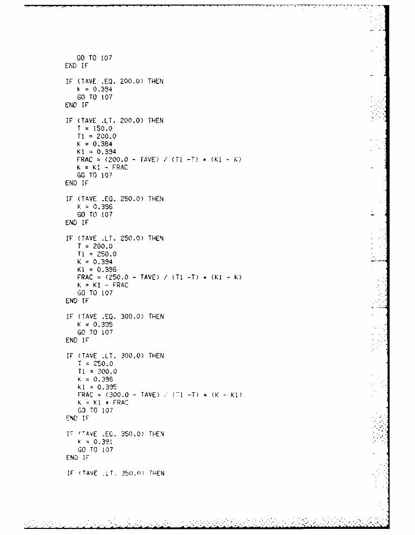
GO TO 107END I F
IF (TAVE .EQ. 200.0) THEN= 0.384
GO TO 107END IF
IF (TAVE .LT. 200.0) THENT = 150.0TI = 200.0K = 0.384KI = 0.394FRAC = (200.0 - TAVE) / (TI -T) • (KI - K)K = Ki - FRACGO TO 107
END IF
IF (TAVE .EQ. 250.0) THENK = 0.396GO TO 107
END IF
IF (TAVE .LT. 250.0) THENT 200.0TI = 250.0K = 0.394KI = 0.336FRAC = (250.0 - TAVE) / (TI -T) , (KI - K)K = Ki - FRACGO TO 107
END IF
IF (TAVE .EQ. 300.0) THENK = 0.395GO TO 107
END IF
IF (TAVE .LT. 300.0) THENT = 250.0TI = 300.0K = 0.396KI = 0.395FRAC = (300.0 - TAVE) (TI -T) * (K - KI)K = KI + FRACGO TO 107
END IF
17 (TAVE .EC. 350.0) TH~ENK = 0.321GO TO 107
END 17
IF (TAVE .LT. 350.0) THEN

APPENDIX E
TFRICT SUBROUTINE

PLTTOT =PLTF + PLTR
* CALCULATE THE SHELL-SIDE FLUID FRICTION FACTOR WHICH** DEPENDS ON THE REYNOLDS NUMBER TAKEN FRGM A CORRELATION
O* F FRICTION FACTORS FOR TUBE BUNDLES WITH 25% CUT*+ SEGMENTAL BAFFLES FROM KERN PAGE 838
CALL SFRICT(RES,SRE,SF,FRS)
** CALCULATE THE SHELL-SIDE PRESSURE LOSS VIA EQUATION** FROM KERN ON PAGE 147
PLSTOT =(FRS *L *(GS**2.0
$ (INT( (L*12.O) I(DSI(N) * PICKS) )+ 1.0 )*0.006944)$ /(2.0 * AG * DENS *(DEQS/12.0)* ((DVS/DVSF) ** 0.14'))
** CHECK TO SEE IF THE PRESSURE LOSSES MEET THE RESTRICTIONS* IMPOSED BY THE USER
IF (PLTTOT .LT. AMAXTP) THENOKT = 1
EL SEOKT =0
END IF
IF (PLSTOT .LT. AMAXSP) THENOKS = I
EL SEOKS = 0
END IF
IF (OKL .EO. I .AND. OKT .EO. I .AND. OKS .EO. 1P THENOKFIN = 1
EL SEOKFIN =0
END IF
RETURNEND

*** CALCULATE THE LENGTH OF TUBING OF THE DESIRED HEAT*** EXCHANGER CONFIGURATION.
IF (PICKP .EQ. 2.0) THENL = ACORR / AL2(N)
END IF
IF (PICKP .EQ. 4.0) THENL = ACORR / AL4(N)
END IF
IF (PICKP .EQ. 6.0) THENL = ACORR / AL6(N)
END IF
IF (PICKP .EQ. 8.0) THEN
L = ACORR / AL8(N)END IF
* CHECK TO SEE IF THE ACTUAL DESIGN LENGTH IS LESS THAN THE*** LENGTH RESTRICTION IMPOSED BY THE USER.
IF (L .LT. LRESTR) THENOKL I
ELSEOKL = 0
END IF
NP = PICKPAG = 32.1740
* CALCULATE THE TUBE-SIDE FLUID FRICTION FACTOR WHICH*** DEPENDS ON THE REYNOLDS NUMBER USING SEIDER AND TATE.** FRICTION FACTOR CORRELATIONS FROM PAGE 836 OF KERN
CALL TFRICT(RET,TRE,TF,FRT)
*** CALCULATE THE PRESSURE LOSSES IN THE TUBE DUE TO BOTH*** THE FRICTION LOSSES AND THE RETURN LOSSES USING**' EQUATIONS FROM PAGE 148 AND 836 OF KERN. NOTE THAT*** .006944 IS A CONVERSION FACTOR FOR PSF TO PSI AND*** .4335 IS A CONVERSION FACTOR FOR FEET OF WATER TO PSI
TAVE = TTAVECALL DWATER(TAVE,DEN)DENW = DEN
PLTF =( FRT*NP*L* (GT**2.0) ) / ( (DTIN/12.0)* 2.0 * AG$ * DENT * (DVT/DVTF)**.14))) 0.00644
PLTR = ( 2.0 * NP (VT**2.0)) / (2.0 * AG *$ (DENT/DENW )) • 0.4335
*** CALCULATE THE TOTAL PRESSURE LOSS IN THE TUBES
. . .... o
. . . . . . . . . . . . . . . . . . . . . . . . . . . . . . . . . . ..L-" - '- ..' - % : I. ".L.j -L-j . :..-j :' L L L' . : L- . -L -:.L-
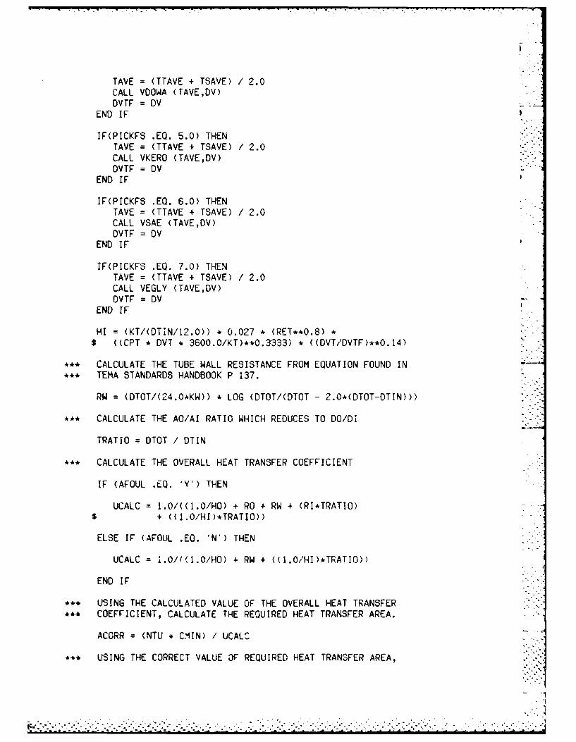
TAVE =(TTAVE +- TSAVE) /2.0CALL VOOWA (TAVE,DV)DVTF =DV
END IF
IF(PICKFS .EQ. 5.0) THENTAVE =(TTAVE + TSAVE) /2.0CALL VKERO (TAVE,DV)DVTF = DV
END IF
IF(PICKFS .EQ. 6.0) THENTAVE = (TTAVE + TSAVE) /2.0CALL VSAE (TAVE,DV)DVTF = DV
END IF
IF(PICKFS .EQ. 7.0) THENTAVE =(TTAVE + TSAVE) /2.0CALL VEGLY (TAVE,DV)DVTF = DV
END IF
HI =(KT/(OTIN/12.0)) *0.027 *(RET**0.8)*
$ ((CPT *DVT *3600.0/KT)**0.3333) *((DVT/DVTF)**0.14)
** CALCULATE THE TUBE WALL RESISTANCE FROM EQUATION FOUND IN** TEMA STANDARDS HANDBOOK P 137.
RW =(DTOT/(4^4.0*KW)) *LOG (DTOT/(DTOT -2.0*(DTOT-DTIN)))
** CALCULATE THE AO/AI RATIO WHICH REDUCES TO DO/DI
TRATIO = DTOT / DTIN
** CALCULATE THE OVERALL HEAT TRANSFER COEFFICIENT
IF (AFOUL .EQ. 'Y') THEN
UCALC = 1.0/((1.0/HO) + RO + RW +(RI*TRATIO)$ + ((1.0/HI )*TRATIO))
ELSE IF (AFOUL .EQ. 'N') THEN
UCALO = .0/?Y1.0/HO) + RW 4 U1.0/HI)*TRATIO))
END IF
** USING THE CALCULATED VALUE OF THE OVERALL HEAT TRANSFER.. COEFFICIENT, CALCULATE THE REQUIRED HEAT TRANSFER AREA.
ACORR = (NTU * CMIN) / UCALC
.* USING THE CORRECT VALUE OF REQUIRED HEAT TRANSFER AREA,

TAVE =(TTAVE + TSAVE) /2.0CALL VGAS (TAVE,DV)DV2-F = DV
END IF
IF(PICKFS .EQ. 4.0) THENTAVE = (TTAVE + TSAVE) /2.0CALL VOOWA (TAVE,DV)DVSF = DV
END IF
IF(PICKFS .EQ. 5.0) THENTAVE = (TTAVE + TSAVE) /2.0CALL VKERO (TAVE,DV)DVSF = DV
END IF
IF(PICKFS .EQ. 6.0) THENTAVE = (TTAVE + TSAVE) /2.0CALL VSAE (TAVE,DV)DVSF = DV
END IF
IF(PICKFS .EQ. 7.0) THENTAVE = (TTAVE + TSAVE) /2.0CALL VEGLY (TAVE,DV)DVSF = DV
END IF
HO =(KS/(DEQS/12.0)) * 0.36 *(RES**0.55)$ ((CPS DVS *3600.0/KS)**0.3333) *((DVS/DVSF)**0.14)
** FROM 'HEAT EXCHANGE TECHNOLOGY' BY STRUTHERS WELLS* CORPORATION P 136
IF(PICKFS .EQ. 1.0) THENTAVE = (TTAVE +TSAVE) /2.0CALL VWATER (TAVE,DV)DVTF =DV
END IF
IF(PICKFS .EQ. 2.0) THENTAVE = (TTAVE + TSAVE) /2.0CALL VMETH (TAVE-,DV)DVTP DV
END IF
IF(PICKFS .EQ. 3.0) THENTAVE = (TTAVE + TSAVE) /2.0CALL 'IGAS (TAVE,DV)DV7F =DV
END
IF(PICKF3 EQ. 4.0) THEN
• ** PROCESS HEAT TRANSFER ON PAGE 139. THE EQUATION IS FOR A* ** TRIANGULAR PITCH ARRANGEMENT ONLY. UNITS ARE IN INCHES.
DEQS=(4.O*((.5*TPH)*(.86*TPH)-((.5*PI*(DTOT**2.))/4.O)))$ /(.5*DTOT)
•** THE VELOCITY OF THE SHELL FLUID IS CALCULATED. UNITS• ** ARE LB/SEC-SQUARE FEET
GS = VS * DENS
*** THE REYNOLDS NUMBER OF THE SHELL FLUID IS CALCULATED
RES = ( (DEQS / 12.0) * GS ) / DVS
• ** THE MASS VELOCITY OF THE TUBE FLUID IS CALCULATED. UNITS• ** ARE LB/SEC-SQUARE FEET
GT = VT * DENT
S** THE REYNOLDS NUMBER OF THE TUBE FLUID IS CALCULATED
RET = ( (DTIN 1 12.0) • GT) I DVT
** NOW THAT THE CONFIGURATION HAS BEEN CHOSEN, CALCULATE THE•** OVERALL U VALUE FOR THE HEAT EXCHANGER USING GENERALIZED• ** CORRELATIONS FOUND IN THE REFERENCES.
•** FROM TEMA PAGE 137, THE OVERALL HEAT TRANSFER COEFFICIENT•** REQUIRES THE EVALUATION OF:
H** HO THE FILM COEFFICIENT OF THE FLUID OUTSIDE THE TUBES** HI : THE FILM COEFFICIENT OF T8HE FLUID INSIDE THE TUBES•** RO : THE FOULING RESISTANCE ON THE OUTSIDE OF THE TUBES•** RI : THE FOULING RESISTANCE ON THE INSIDE OF THE TUBES•** RW : THE RESISTANCE OF THE TUBE WALL REFERRED TO THE
OUTSIDE SURFACE OF THE TUBE WALL** AO/Al • THE RATIO OF OUTSIDE TO INSIDE SURFACE OF TUBING- -
•** FROM 'HEAT EXCHANGE TECHNOLOGY' BY STRUTHERS WELLS• ** CORPORATION P 157
IF(PICKFS •EQ. 1.0) THENTAVE = (TTAVE + TSAVE) 2.0CALL VWATER (TAVE,DV)DVSF : DV
END IF
IF(PICKFS EQ. 2.0) THENTAVE = (TTAVE * TSAVE' / 2.0CALL VMETH (TAVE,DV)DVSF = DV
END IF
IF(PICKFS EQ. 3.0) THEN
S. -,. -
. . . . . . . . . . . . . .. . . .. % . . . . .. -.. ".. . .-.- I
. . . . . . . .. . . . . . . . . . . . . . . . . . . . . . . . .
.. .> .. -'. " "1 i- .- .1 .' .> .-'>> '. '.--> > >i>'1', - '- >11-.1 ->.i 1i .71.---1,. > > i- .i .,-' L -L-'3 ' ..-'> L"-L'.> I'.L-L

SUBROUTINE PRESCK (DSIU,TPH,TC,PICKS,DSI,MS,ASC,MT,ATIN,$ PICKP,NT2,NT4,NT6,NT8,PI,DTOT,DENS,DVS,DENT,$ DTIN,DVT,PICKFS,TTAVE,TSAVE,DV,KS,CPS,KT,CPT,KW,$ AFOUL,RO,RW,RI,NTU,CMIN,AL2,AL4,AL6,ALS,TRE,TF,$ SRE,SF,LRESTR,OKFIN,AMAXTP,AMAXSP,PICKD)
*** THIS SUBROUTINE DOES A PRESSURE CHECK ON BOTH THE TUBE*** AND THE SHELL SIDES, AND ALSO DOES A LENGTH RESTRICTION*** CHECK. IF THE SUBROUTINE RETURNS THE VALUE OF OKFIN = I.** THE CONFIGURATION MET THE CRITERIA. A VALUE OF OKFIN = 0+** MEANS THAT THE CONFIGURATION FAILED ONE OR MORE OF THE*** DESIGN CRITERIA IMPOSED BY THE USER.
DIMENSION DSIU(28),DSI(28),NT2(28),NT4(28),NT6(28),$ NT8(28),AL2(28),AL4(28),AL6(28),AL8(28),TRE(34),$ TF(34),SRE(34),SF(34)
CHARACTER*I AFOUL
REAL NTU,MT,MS,LRESTR,NP,KS,KT,KW,L
N = INT( (PICKD/2.0) - 2.0
*** FOR EACH HEAT EXCHANGER CONFIGURATION , THE PROGRAM CAN NOW*** THE ACTUAL SHELL AND TUBE FLUID VELOCITIES, AND DO A LENGTH*** RESTRICTION CHECK, A SHELL PRESSURE LOSS CHECK, AND A TUBE*** PRESSURE LOSS CHECK.*** NOTE THAT C IS A CONVERSION FACTOR TO GET VELOCITY UNITS IN --
*** FT/SEC BY INPUTTING A FLOW RATE OF GALLONS PER MINUTE AND*** HAVING AREA IN INCHES.
C = .3208342
ASC = (DSIU(N)/TPH) * TC * (PICKS * DSI(N))
VS C * MS/ASC
IF (PICKP .EQ. 2.0) THENVT = (C*MT) / (ATIN * (NT2(N)/2.0)
END IF
IF (PICKP .EO. 4.0) THENVT = (C*MT) / (ATIN * (NT4(N)/4.0)
END IF
IF (PICKP .EQ. 6.0) THENVT = (C*MT) / (ATIN * (NT6(N)/6.0)
END IF
lF (PICKP .EQ. 8.0) THENVT = (C*MT) / (ATIN * (NT8(N)/9.O)
END IF
*** CALCULATE THE EQUIVALENT DIAMETER OF THE FLUID CONDUIT*.* CROSSING THE TUBES USING EQUATIONS FROM KERN IN HIS BOOK
I

APPENDIX D
PRESCK SUBROUTINE
DY 0.000064GO TO 102
END IF
IF (TAVE .LT. 550.0) THENT = 500.0TI= 550.0V 0.000071Vi = 0.000064FRAC = (550.0 -TAVE) /(TI T) *(V -VI)
DV = Vi + FRACGO TO 102
END IF
IF (TAVE .EQ. 600.0) THENDV = 0.000058GO TO 102
END IF
IF (TAVE .LT. 600.0) THENT = 550.0TI = 600.0V = 0.000064Vi = 0.000058FRAC = (600.0 -TAVE) /(Ti- T) *(V -Vi)
DV = V1 + FRACGO TO 102
END IF
IF (TAVE .GT. 600.0) THENDV =0.000058
END IF
102 RETURNEND
TI =350.0
V =0.000126
Vi =0.000105FRAC =(350.0 -TAVE) /(TI -T) *(V -Vi)
DV = VI + FRACGO TO 102
END IF
IF (TAVE .EQ. 400.0) THENDV = 0.000091GO TO 102
END IF
IF (TAVE .LT. 400.0) THENT = 350.0TI = 400.0V = 0.00010~5Vi = 0.000091FRAC =(400.0 -TAVE) /(TI- T) *(V -VI)
DV = V11 + FRACGO TO 102 -
END IF
IF (TAVE .EQ. 450.0) THENDV = 0.000080GO TO 102
END IF
IF (TAVE .LT. 450.0) THENT =400.0Ti= 450.0V =0.000091V1 = 0.000080FRAC = (450.0 -TAVE) /(TI- T) *(V -VI)
DV = Vi + FRACGO TO 102
END IF
IF (TAVE .EQ. 500.0) THENDV = 0.000071GO TO 102
END IF
IF (TAVE .LT. 500.0) THENT = 450.0TI 500.0V = 0.000080Vi 0.000071FRAC = (500.0 -TAVE) /(TI -T * (V -VI)DV = VI + FRACGO TO 102
END IFL
IF (TAVE .EQ. 550.0) THEN

END I F
IF (TAVE .EQ. 200.0) THENDV = 0.000205GO TO 102
END IF
IF (TAVE .LT. 200.0) THENT = 150.0TI = 200.0V = 0.000292VI = 0.000205FRAC = (200.0 -TAVE) /(TI- T) *(V -VI)
DV = Vi + FRACGO TO 102
END IF
IF (TAVE .EQ. 250.0) THENDV = 0.000158GO TO 102
END IF -
IF (TAVE .LT. 250.0) THENT =200.0Ti= 250.0V =0.000205Vi 0.000158FRAC = (250.0 -TAVE) /(Ti- T) *(V -VI)
DV = Vl + FRACGO TO 102
END IF
IF (TAVE .EQ. 300.0) THENDV = 0.000126GO TO 102
END IF
I F (TAVE .LT. 300.0) THENT = 250.0Ti= 300.0V = 0.000158VI 0.000126FRAC = (300.0 -TAVE) /(Ti T) *(V -VI)
DV = VI + FRACGO TO 102
END IF
IF (TAVE .EQ. 350.0) THENDV = 0.000105GO TO 102
END IF
IF (TAVE .LT. 350.0) THENT =300.0

SUBROUTINE VWATER(TAVE,DV)*** THIS SUBROUTINE CALCULATES THE DYNAMIC VISCOSITY OF*** WATER AT THE AVERAGE FLUID TEMPERATURE FOR TEMPERATURES*** FROM 32.0 DEG F TO 600 DEG F. UNITS ARE LB/FT-SEC
IF (TAVE .LE. 32.0) THENDV = 0.0012GO TO 102
END IF
IF (TAVE .EQ. 50.0) THENDV = 0.00088GO TO 102
END IF
IF (TAVE .LT. 50.0) THENT = 32.0TI = 50.0V = 0.0012Vi = 0.00088FRAC = (50.0 - TAVE) / (TI - T) * (V - VI)DV = Vi + FRACGO TO 102
END IF
IF (TAVE .EQ. 100.0) THENDV = 0.000458GO TO 102
END IF
IF (TAVE .LT. 100.0) THENT = 50.0T! = 100.0V = 0.00088V! = 0.000458FRAC = (100.0 - TAVE) / (TI - T) * (V - VI)DV = VI + FRACGO TO 102
END IF
IF (TAVE .EQ. 150.0) THENDV = 0.000232GO TO 102
END IF
IF (TAVE .LT. 150.0) THENT 100.0TI= 150.0V =0.000458VI = 0.000292FRAC = (150.0 - TAVEt / (Tj - T) (V - Vl)DV = V. + FRACGO TO 102
- S. ... . . . .. . . . . . . . . . . . . . . . . . . .

IF (TAVE .EQ. 550.0) THENK = 0.325GO TO 107
END IF
IF (TAVE .LT. 550.0) THENT =500.0Ti 550.0K =0.349
KI =0.325
FRAC = (550.0 -TAVE) /(Ti -T) *(K -Ki)
K = Ki + FRACGO TO 107
END IF
IF (TAVE .EQ. 600.0) THENK = 0.292GO rO 107
END IF
IF (TAVE .LT. 600.0) THENT =550.0TI 600.0K =0.325Ki 0.292FRAC = (600.0 -TAVE) /(TI -T) *(K -Ki)
K = KI + FRAC-GO TO 107
END IF
IF (TAVE .GT. 600.0) THENK = 0.292
END IF
107 RETURNEND
T = 300.0TI = 350.0K = 0.395KI = 0.391FRAC = (350.0 - TAVE) / (TI -T) * (K - KI)K = KI + FRACGO TO 107
END IF
IF (TAVE .EQ. 400.0) THENK = 0.381GO TO 107
END IF
IF (TAVE .LT. 400.0) THENT = 350.0Ti = 400.0K = 0.391KI = 0.381FRAC = (400.0 - TAVE) / (TI -T) (K - Ki)K = KI + FRACGO TO 107
END IF
IF (TAVE .EQ. 450.0) THENK = 0.367GO TO 107
END IF
IF (TAVE .LT. 450.0) THENT = 400.0TI = 450.0K = 0.381KI = 0.367FRAC = (450.0 - TAVE) / (TI -T) * (K - KI)K = Ki + FRAC
GO TO 107ENC IF
IF (TAVE .EQ. 500.0) THENK = 0.349GO TO !07
END IF
IF (TAVE .LT. 500.0) THENT 450.0TI : 500.0K = 0.367K= 0.349FRAC = (500.0 - IAVE) I (TI -T) • (K - KI)K = KI + FRACGO TO 107
END IF
. .-

SUBROUTINE TFRICT(RET,TRE,TF,FRT)
* ** THIS SUBROUTINE CALCULATES THE TUBE-SIDE FRICTION FACTOR• ** FOR USE IN THE DARCY-FANNING PRESSURE LOSS EOUATION FOR• ** THE TUBE-SIDE PRESSURE DROP DUE TO FRICTION. THE FACTOR• ** IS INTERPOLATED FROM VALUES TAKEN FROM A GRAPH OF TUBE-• ** SIDE FRICTION FACTORS PUBLISHED BY TEMA. THE FRICTION• ** FACTOR IS A DIMENSIONLESS PARAMETER.
DIMENSION TRE(34),TF(34)
IF(RET .LE. TRE(I)) THENFRT = TF(I)GO TO 104
END IF
DO 103, I= 2,34IF(RET .LT. TRE(I)) THEN
FRAC = (TRE(1)-RET)/(TRE(1)-TRE<I-1))*(TF(I-1)-TF(1))FRT = TF(I-1) - FRACGO TO 104
END IF
IF(RET .EQ. TRE(I)) THENFRT = TF(I)GO TO 104
END IF
103 CONTINUE
PRINT*,' THE TUBE-SIDE FLUID REYNOLDS NUMBER IS OUT OF'PRINT*,'RANGE OF THE PROGRAM. AN AVERAGE FRICTION'PRINT*,'FACTOR OF 0.035 WILL BE USED IN CALCULATIONS.'
FRT = 0.035
104 RETURNEND
....................... 2 A.'.

APPENDIX F
SFRICT SUBROUTINE

It
SUBROUTINE SFRICT(RESSRESFFRS)
*** THIS SUBROUTINE CALCULATES THE SHELL-SIDE FRICTION FACTOR*** FOR USE IN THE DARCY-FANNING PRESSURE LOSS EQUATION FOR*** THE SHELL-SIDE PRESSURE DROP DUE TO FRICTION. THE FACTOR*** IS INTERPOLATED FROM VALUES TAKEN FROM A GRAPH OF SHELL-*** SIDE FRICTION FACTORS PUBLISHED BY KERN IN HIS BOOK PROCESS*** HEAT TRANSFER. THE FRICTION FACTOR IS A DIMENSIONLESS*** PARAMETER.
DIMENSION SRE(34),SF(34)
IF(RES .LE. SRE(I)) THENFRS = SF(I)GO TO 106
END IF
DO 105, 1= 2,34IF(RES .LT. SRE(1)) THEN
FRAC = (SRE(I)-RES)/(SRE(I)-SRE(I-1))*(SF(I-I)-SF(I))FRS = SF(I-1) - FRACGO TO 106
END IF
IF(RES .EQ. SRE(I)) THENFRS = SF(I)GO TO 106
END IF
105 CONTINUE
PRINT*. THE SHELL FLUID REYNOLDS NUMBER IS OUT OF'PRINT* 'RANGE OF THE PROGRAM. AN AVERAGE FRICTION'PRINT*,'FACTOR OF 0.30 WILL BE USED IN CALCULATIONS.'
FRS = 0.30
106 RETURNEND
. . . . . . . . .. . .
"," 4 .....................................""...". ."....."." "-."- ."" . .. ."." ' "-" " ' ' " "" " . ". .'" "

APPENDIX G
PRINT SUBROUTINES

SUBROUTINE PRINT2(J,J2,PICKS,PICKD)
~* THIS SLUBPROGRAM PRINTS OUT THE AVAILABLE EXCHANGER
** CONFIGURATIONS FOR 2-PASS CONSTRUCTION
IF (J .EQ. 0) THENPRINT*,PRINT*,'THE AVAILABLE HEAT EXCHANGER'PRINT*,'CONFIGURATIONS ARE AS FOLLOWS:'PRINT* ,
END IF
IF (J2 .EQ. 0) THENPRINT*,'PRINT*,'THE AVAILABLE 2-PASS HEAT EXCHANGER'PRINT*,'CONFIGURATIONS ARE AS FOLLOWS:'PRINT* ,J2 I
END IF
PRINT* , 'SHELL DIAMETER',PICKD,' INCHES:'PRINT*,'WITH A ',PICKS,' BAFFLE SPACING'
RETURNEND

SUBROUTINE PRINT4(J,J4,PICKS,PICKD)
*** THIS SUBPROGRAM PRINTS OUT THE AVAILABLE EXCHANGER*** CONFIGURATIONS FOR 4-PASS CONSTRUCTION
IF (J .EQ. 0) THENPRINT*,_PRINT*, THE AVAILABLE HEAT EXCHANGER'PRINT*, 'CONFIGURATIONS ARE AS FOLLOWS:'PRINT*,'J= I
END IF
IF (J4 .EQ. 0) THENPRINT*,'PRINT*,'THE AVAILABLE 4-PASS HEAT EXCHANGER'PRINT*,'CONFIGURATIONS ARE AS FOLLOWS:'PRINT*,'J4 =I
END IF
PRINT*, 'SHELL DIAMETER' ,PICKD,' INCHES:'PRINT*,'WITH A ',PICKS,' BAFFLE SPACING'
RETURNEND
., .
SUBROUTINE PRINT6(J,JS,PICKS,PICKD)
* THIS SLUBPROGRAM PRINTS OUT THE AVAILABLE EXCHANGER** CONFIGURATIONS FOR 6-PASS CONSTRUICTION
IF (J .EQ. 0) THENPRINT*,'PRINT*, 'THE AVAILABLE HEAT EXCHANGER'PRINT*,'CONFIGURATIONS ARE AS FOLLOWS:'PRINT*,'J = 1
END IF
IF (J6 .EQ. 0) THENPRINT*,'PRINT*,'THE AVAILABLE 8-PASS HEAT EXCHANGER'PRINT*,'CONFIGURATIONS ARE AS FOLLOWS:'PRINT*,'J6 I
END IF
PRINT*, 'SHELL DIAMETER' ,PICKD,' INCHES:'PRINT*,'WITH A ',PICKS,' BAFFLE SPACING'
RETURNEND

SUBROUTINE PRINTS(J,J8,PICKS,PICKD)
** THIS SUBPROGRAM PRINTS OUT THE AVAILABLE EXCHANGER** CONFIGURATIONS FOR 8-PASS CONSTRUCTION
IF (J .EQ. 0) THENPRINT*,PRINT*,'THE AVAILABLE HEAT EXCHANGER'0PRINT*,'CONFIGURATIONS ARE AS FOLLOWS:'PRINT*,'J =I
END IF
IF 068 EQ. 0) THENPRINT*,'PRINT*,'THE AVAILABLE 8-PASS HEAT EXCHANGER'PRINT*, 'CONFIGURATIONS ARE AS FOLLOWS:'PRINT*,'JS I
END IF .
PRINT*, 'SHELL DIAMETER' ,PICKD,' INCHES:'PRINT*,'WITH A ',PICKS,' BAFFLE SPACING'
RETURNEND
.7,
- .. . . . . 7 -7
FILMED
6-85
DTIC