design of silicon micro-resonators with low mechanical and optical losses for quantum optics...
TRANSCRIPT

1 3
Microsyst Technol (2014) 20:907–917DOI 10.1007/s00542-014-2078-y
TechnIcal PaPer
Design of silicon micro‑resonators with low mechanical and optical losses for quantum optics experiments
A. Borrielli · M. Bonaldi · E. Serra · A. Bagolini · P. Bellutti · F. S. Cataliotti · F. Marin · F. Marino · A. Pontin · G. A. Prodi · G. Pandraud · P. M. Sarro · G. Lorito · T. Zoumpoulidis
received: 31 July 2013 / accepted: 7 January 2014 / Published online: 29 January 2014 © Springer-Verlag Berlin heidelberg 2014
relatively thick silicon oscillators with high reflectiv-ity coating. The relatively high mass is compensated by the capability to manage high power at low temperatures, owing to a favourable geometric factor (thicker connectors) and the excellent thermal conductivity of silicon crystals at cryogenic temperature. We have measured at cryogenic temperatures mechanical quality factors up to 105 in a micro-oscillator designed to reduce as much as possible the strain in the coating layer and the consequent energy dissi-pation. This design improves an approach applied in micro-mirror and micro-cantilevers, where the coated surface is reduced as much as possible to improve the quality factor. The deposition of the highly reflective coating layer has been carefully integrated in the micro-machining process to preserve its low optical losses.
Abstract The interaction of the radiation pressure with micro-mechanical oscillators is earning a growing inter-est for its wide-range applications and for fundamental research. In this contribution we describe the fabrica-tion of a family of opto-mechanical devices specifically designed to ease the detection of ponderomotive squeez-ing and of entanglement between macroscopic objects and light. These phenomena are not easily observed, due to the overwhelming effects of classical noise sources of ther-mal origin with respect to the weak quantum fluctuations of the radiation pressure. a low thermal noise background is required, together with a weak interaction between the micro-mirror and this background (i.e. high mechanical quality factors). In the development of our opto-mechan-ical devices, we heve explored an approach focused on
a. Borrielli (*) · M. Bonaldi Institute of Materials for electronics and Magnetism, nanoscience -Trento-FBK Division, Via alla cascata 56/c, 38123 Trento, Tn, Italye-mail: [email protected]
a. Borrielli · M. Bonaldi · e. Serra · a. Pontin · G. a. Prodi Istituto nazionale di Fisica nucleare (InFn), Gruppo collegato di Trento, 38123 Trento, Tn, Italy
e. Serra Interdisciplinary laboratory for computational Science (lISc), FBK-University of Trento, 38123 Trento, Tn, Italy
e. Serra · G. Pandraud · P. M. Sarro Department of Microelectronics and computer, engineering /ecTM /DIMeS, Feldmanweg, 17, cT 2628 Delft, The netherlands
a. Bagolini · P. Bellutti Microtechnology laboratory FBK-cMM, 38123 Trento, Tn, Italy
F. S. cataliotti · F. Marin Dipartimento di Fisica e astronomia, Università di Firenze, 50019 Sesto Fiorentino, FI, Italy
F. S. cataliotti · F. Marin · F. Marino european laboratory for non-linear Spectroscopy (lenS), 50019 Sesto Fiorentino, FI, Italy
F. S. cataliotti · F. Marin · F. Marino Sezione di Firenze, InFn, 50019 Sesto Fiorentino, FI, Italy
F. Marino cnr-InO, l.go enrico Fermi 6, 50125 Firenze, Italy
a. Pontin · G. a. Prodi Dipartimento di Fisica, Università di Trento, 38123 Trento, Tn, Italy
G. lorito · T. Zoumpoulidis Iszgro Diodes BV, P.O. 3032, Da 2601 Delft, The netherlands

908 Microsyst Technol (2014) 20:907–917
1 3
1 Introduction
The interaction of light with mechanical oscillators medi-ated by radiation pressure has been investigated for many years since the 80s, permitting the observation of physical phenomena such as optical spring effect, optical damping effect, dynamical back action, slowing and confinement and dynamical instabilities. however, all these phenomena are related to a classical description of the radiation pressure effects, while the most fascinating aspect of this research field is linked to the possibility to enhance the interaction between light and matter with optical cavities and to create quantum mechanically controllable systems where the opti-cal and mechanical degree of freedom are coupled by the radiation pressure of the light. Thanks also to technological advances in microfabrication, new opto-mechanical devices have allowed to obtain significant results in studies of fun-damental physics, but also in a wide-range applications, including high sensitivity measurements of position, force and mass (Kippenberg and Vahala 2008; Marquardt and Girvin 2009; Favero and Karrai 2009; aspelmeyer et al. 2010). currently most of the researches related to cavity opto-mechanics are dedicated to the realization of experi-ments enabling the detection of quantum opto-mechanical phenomena in the behavior of systems involving macro-scopic objects, such as the suspended mirrors of an optical resonator.
This branch of research has recently achieved the obser-vation and manipulation of quantum properties of light through mechanical interaction, namely the observation of the shot-noise in the radiation pressure (Purdy et al. 2013a) and the production of ponderomotive squeezing (Safavi-naeini et al. 2013; Purdy et al. 2013b), i.e., of a non-clas-sical state of light with noise smaller than the standard quantum limit (Fabre et al. 1994; Mancini and Tombesi 1994). experimental systems enabling the observation of this phenomenon will also allow other, even more relevant investigations, such as quantum nondemolition measure-ments, quantum correlation and eventually the creation of entangled states of light and one or more oscillators (Verlot et al. 2009; Jacobs et al. 1994; clerk et al. 2008; Vitali et al. 2007). These phenomena are not easily observed, mainly due to the intrinsic weakness of the quantum fluctuations of light compared to the “technical” noises, first of all the thermal noise, overwhelming the noises of quantum nature (radiation pressure noise and shot noise) through which it would be possible an observation of quantum properties of the electromagnetic field in its mechanical interaction with the macroscopic oscillator.
according to the cavity dynamics, some fundamental requirements for the oscillator may be derived by compar-ing the power spectral density (PSD) of the radiation pres-sure noise (SRP) and the PSD of the thermal noise (ST). For
instance, in view of the production of quantum effects like the ponderomotive squeezing, we require that the radiation pressure force noise due to quantum fluctuations dominates over displacement thermal noise at temperature T:
where T and L are respectively the input mirror intensity transmission and the cavity losses, ωL the angular fre-quency of the laser, F = 2π/(T + L) the finesse (F/π quantifies the mean number of reflections made by the photons before leaving the cavity), M the effective mass and �m/2π the resonating frequency of the oscillator, and Pin the input laser power. equation 1 sets the regime where the generation of squeezed light can be obtained as a result of the quantum optomechanical correlations between field quadratures. as evident from the right-hand side of the equation (thermal noise contribution), the success of experiments of this nature benefits from a low effective mass and frequency of the mechanical oscillator, but espe-cially from a weak interaction between the mechanical system and its background (indicated by a high mechani-cal quality factor Q). In view of the control of the thermal noise background and the reinforcement of the quantum fluctuations inside an opto-mechanical cavity, an accu-rate control of the optomechanical properties of the sys-tem seems to be the main strategy through which to detect quantum opto-mechanical phenomena (anetsberger et al. 2008; cole et al. 2011).
Several kinds of oscillators are currently tested, such as breathing whispering galleries (Schliesser et al. 2008; Weis et al. 2010), thin membranes working as refractive oscil-lators within high Finesse cavities (Thompson et al. 2008; Wilson et al. 2009), and photonic crystal optomechani-cal cavities (chan et al. 2011; Safavi-naeini et al. 2012). Focusing our interest to Fabry-Perot interferometers with oscillating mirrors, we mention that very low mass oscilla-tors have recently been conceived and tested, based on free-standing dielectric multi-layer reflectors (Gigan et al. 2006; cole et al. 2008; Kuhn et al. 2011) or on tiny mirrors on shaped thin membranes (Kuhn et al. 2011; Gröblacher et al. 2009a, b; Kleckner et al. 2011).
In the present paper, we explore a different approach focusing on thicker silicon oscillators with an effective mass relatively higher, if compared to devices previously cited, but for which the main goal is the minimization of the thermal noise by means of a strong reduction of the energy losses. The high mass is compensated by the pos-sibility to manage high power at low temperatures, thanks to the favourable geometric factor (thicker connectors) and the high thermal conductivity of silicon at cryogenic tem-perature (Klitsner et al. 1988). Moreover, the deposition of
(1)�ωLPin
4
c2
(
2T
T + L
)2(F
π
)2
> 2kBTM�m
Q

909Microsyst Technol (2014) 20:907–917
1 3
an high reflectivity micro-mirror, integrated in the micro-machining process, ensures a very high cavity finesse improving the optical performances.
Many experiments reported in the literature have dem-onstrated that single-crystal silicon mechanical resona-tors (10 × 10 × 10 cm3) can show loss angles as small as Q−1
= 10−9 at low temperatures. For smaller systems this figure reduces proportionally to their characteristic size (Mohanty et al. 2002), due to the intrinsic dissipation mech-anisms characterizing microscopic and submicroscopic structures at low temperature. Therefore for the devices we propose, which have a characteristic size of about 100µm (see Sect. 5), the best result obtainable in terms of loss angle is around Q−1 = 10−6 (liu et al. 2005; Zendri et al. 2008), a value that, together with the other characteristic parameters of our experimental set-up, is sufficient to reach the condition SRP > ST (Serra et al. 2012c). Unfortunately this limit value is not easily accessible because of the vari-ous phenomena concurring to degrade the performances of a mechanical oscillator.
Usually the energy dissipation is determined by a com-bination of various mechanisms which dominate in differ-ent subsystems of the oscillator. Since dissipation is the rate at which energy is lost from a resonant mode to the environments coupled to the mode, the dominant mecha-nism is the one with the highest rate of energy loss. For each resonant mode, the loss angle is defined as φT =
�WT
2πWT
where WT is the total energy stored in the resonant mode and �WT the total energy loss per oscillation cycle. The quality factor of the mode is simply QT = φT
−1. In our case, oscillators are composed of two subsystems: the silicon and the high reflectivity coating which is composed by a depo-sition of alternating layers of Ta2 O5/SiO2 (see Sect. 5) For these coatings the loss angle is independent from the tem-perature (Yamamoto et al. 2006) and it is about 5 × 10⁻⁴, two orders of magnitude greater than the expected value for silicon. In a resonator made of two subsystems of differ-ent materials, the total loss is given by the sum of the loss angle of each subsystem, weighted by the corresponding strain energy ratio:
where Ws and Wc are the strain energy stored, respectively, in the silicon and in the coating.
These considerations show as the mechanical perfor-mances of micro-mirrors are strongly limited by the optical coatings, nevertheless fundamental in experiments of opto-mechanics. an accurate analysis of the possible strategies to minimize the coating loss will be provided in Sect. 2 along with some examples.
a second critical point affecting the mechanical per-formances of resonant devices is the poor experimental
(2)Q−1T = φs
Ws
WT
+ φc
Wc
WT
reproducibility of the losses. These can depend not only on the intrinsic characteristics of the oscillator or its envi-ronment, but also on the particular clamping method used to link the resonator to the support. In fact, for the vibrat-ing modes of a resonator the maximum strain can arise at the clamping part of the sample holder. as a result a large fraction of the total elastic energy is located there and can be easily dissipated by the sample holder. This originates an additional contribution to the damping of the resonator which frequently overwhelms the internal losses. In Sect. 3 we describe the design concepts at the basis of the “nodal suspension” and other approaches to reduce the clamp-ing losses. In Sect. 4 we discuss the thermal stability of the devices and finally in Sects. 5 and 6 we show the pro-duction process of the resonators and we report our final remarks.
2 Minimization of the coating loss
In cavity opto-mechanics experiments, the core of the problem is the enhancement of radiation pressure interac-tion between electromagnetic radiation and a mechanical oscillator. The efficiency of the optical coupling can be improved by the deposition of coating layers of high reflec-tivity material. The mechanical micro-oscillators proposed in this paper are conceived to confine the high-reflectiv-ity coating on a part moving as rigidly as possible. This reduces the strain energy stored in the coating layer that is a major source of mechanical dissipation in oscillating micro-mirror (Serra et al. 2012a, b; Waggoner and craig-head 2009; Sosale et al. 2011). This feature also allows for relatively large mirror diameters, giving negligible diffrac-tion losses and thus facilitating the achievement of a high finesse.
In Fig. 1 two different variations of the device are shown. Figure 1a reports a SeM image of a typical “stand-ard” oscillator fabricated on a silicon-on-insulator (SOI) wafer where the handle layer is 400 μm while the device layer is 70 μm with a buried oxide of 2 μm. each oscil-lator is composed of a round mass suspended by eight beams, and a subsequent isolation wheel that is inter-posed between the central part of the device and the sili-con wafer. The central disk is the main part of the devices where the radiation of the cavity is focused, and Fig. 1c shows the modal shape of its fundamental mechanical mode. The contour plot represents the vertical displace-ment of the structure, from 0 (blue) to a maximum arbi-trary value (red) with amplitude exaggerated for clarity. In this configuration the bending of the flexural members introduces a comparable bending also in the disk thus increasing the strain energy stored in the central disk. a significant reduction of the energy dissipated per cycle is

910 Microsyst Technol (2014) 20:907–917
1 3
achieved if the optical coating is deposited only on the central disk. In fact, we have observed (Serra et al. 2012b) that for the two different configurations of the coating, the first one covering the whole front face of the wafer includ-ing the central round mass and the supporting beams (full coating), and the second one covering just the central disk (central coating), the mechanical quality factor measured at room temperature for a typical device increases from about 6 × 10³ to about 17 × 103.
a subsequent improvement of these devices can be obtained by reducing the strain of the central mirror during the oscillation. In Fig. 1b a SeM image of a typical “low deformation” mirror is reported, whose mechanical struc-ture, made of alternate torsional and flexural springs sup-porting the oscillating mass, allows vertical displacements
(Fig. 1d) with a minimal internal deformation. Indeed, most of the deformations associated to the fundamental mechanical mode are absorbed by the structures, not cov-ered by the optical coating during the micro-fabrication. This design permits an almost uniform vertical displace-ment of the mirror over the coated area and reduces the strain energy ratios stored in the coating from 6.4 × 10⁻² for the standard design (Fig. 2a) to 4.2 × 10⁻³ for the low deformation design (Fig. 2b).
In Table 1, we report the quality factor measured in our best low deformation mirror oscillator (D1) compared with the results obtained with the standard device (D0). The resonant frequency of each device is determined by the noise displacement spectrum of the mirror’s surface, measured by a Michelson interferometer with a balanced
Fig. 1 Images of two different versions of micro opto-mechanical resonators with fundamental mechanical mode resonating at ≈150 khz. a, b are SeM images of the front side of a “standard” and of a “low deformation” oscillating mirror. In both cases the beams con-necting the central mass with the support are 50 or 100 μm wide, with length ranging from 300 to 450 μm depending on the target fre-quency of the device. The thickness of the central disk is about 70 μm. The optical coating layer covers only the central disk in order to minimize the coating energy loss. Images c and d show the modal shape of the fundamental mechanical mode of the two devices. The
central circle indicates the area covered with the reflective coating. The contour plot shows the vertical displacement of the structure, from 0 (blue) to a maximum arbitrary value (red). The amplitude of the displacement has been exaggerated for clarity. c Standard design: the mirror is supported by radial flexural springs and the bending of the flexural members induces a significant bending also in the disk. d “low deformation” design: the vertical displacement of the mirror is almost uniform over the coated area, thanks to the structure made of alternated torsional and flexural springs. The devices have been real-ized at Fondazione Bruno Kessler (FBK) micro-fabrication facility

911Microsyst Technol (2014) 20:907–917
1 3
homodyne detection scheme (Serra et al. 2012b; Marino et al. 2010; Pontin et al. 2014). at room temperature, the quality factor of the device D1 is greater than that of the standard device D0. In fact, at room temperature the thermoelastic effect is the main cause of energy dissipa-tion in both devices, but the quality factor of D0 is further reduced by a comparable dissipation added by the coat-ing layer. This is evident in the measurements at cryo-genic temperature, where thermoelastic loss becomes negligible and the quality factor of D1 grows up to 105, even if it still remains below the prediction based on eq. 2. These observations suggest that the low deforma-tion mirror design is effective in reducing losses from the coating layer, but some other dissipative phenomena become dominant and do not allow to reach the expected system performances.
3 Minimization of the clamping loss
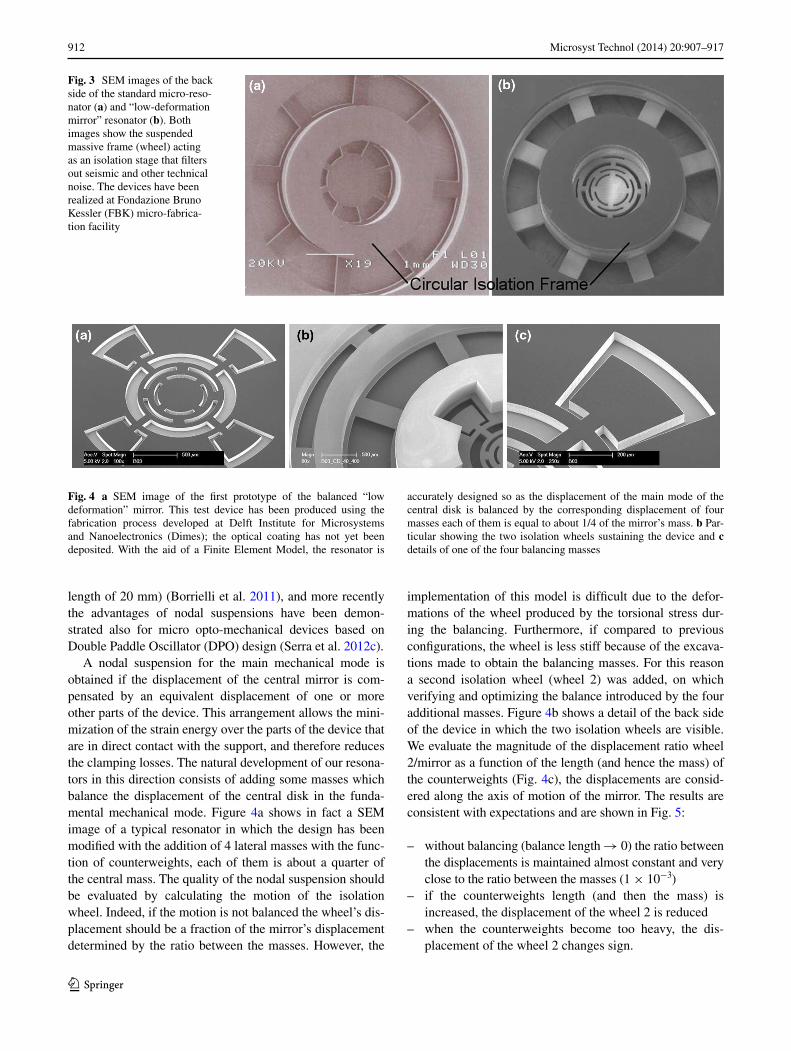
a second source of loss in the system is the coupling between the main resonant mode of the device and the inter-nal modes of the wafer. actually, the loss factor of the wafer is well above the intrinsic loss of silicon, due to the dissipa-tion introduced by the sample holder. Moreover, some kind of coupling with the device is practically unavoidable, as the membrane modes of the wafer cover the full frequency spectrum with a spacing of the order of 2 khz. as shown in Fig. 3, reporting a SeM image of the back side of the standard device (Fig. 3a) and of the low deformation device (Fig. 3b) previously described, in order to reduce this dissi-pative effect each resonator is connected to the silicon wafer through a suspended frame (the wheel), acting as an isola-tion stage that filters out seismic and other technical noise and reduces the coupling between the resonant modes of the main oscillator and the internal modes of the wafer and the sample holder. Indeed, using a simple masses-springs model (Serra et al. 2012a) it can be demonstrate that, if a loss angle as low as 5 × 10⁻⁶ is assigned to the resonator and the sus-pended frame, the resulting total loss factor of the resonator mode can just worsen by less than one order of magnitude, depending on the frequency and the loss of the wafer mode. If instead the isolation wheel is absent, the resulting loss fac-tor is strongly correlated to the loss of the wafer mode. Thus a complete device may be thought as made of three parts (resonator, coating, and frame): its overall mechanical per-formances are given by the interplay between the properties of each part and are strongly dependent on the modal shape.
These tricks, even though being a progressive improve-ment of the mechanical performances, do not allow to reach the expected dissipation limit. In fact, the best result for the suspended resonators remains one order of magni-tude larger than expected (Table 1).
To overcome this gap we decided to implement a nodal suspension for the micro-resonators, that is the oscillators are supported from the nodal points of the resonant mode, in order to minimize the reaction forces at the mount point and to obtain a clamping loss almost independent from the mechanical impedance of the holder and its internal dissipa-tion. Very good performances have been obtained in nodally suspended macroscopic resonators (with a characteristic
Fig. 2 Finite element model showing the strain energy distribu-tion into the main parts of the micro resonators during an oscillation cycle. The use of alternate torsional and flexural springs supporting the central mirror permits an almost uniform vertical displacement of the mirror over the coated area and reduces the strain energy ratios stored in the coating from 6.4 × 10⁻² for the standard design (a) to 4.2 × 10⁻³ for the low deformation design (b)
Table 1 experimental parameters of the devices
D0 = standard oscillator. D1 = low-deformation mirror oscillator. f = frequency of the main mode
T (K) f (khz) Q
D0 295 212 17 × 103
D1 295 129 28 × 103
D1 10 129 100 × 103
912 Microsyst Technol (2014) 20:907–917
1 3
length of 20 mm) (Borrielli et al. 2011), and more recently the advantages of nodal suspensions have been demon-strated also for micro opto-mechanical devices based on Double Paddle Oscillator (DPO) design (Serra et al. 2012c).
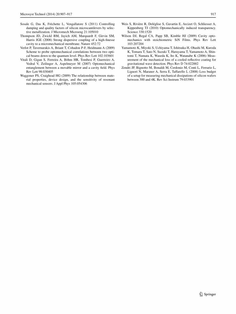
a nodal suspension for the main mechanical mode is obtained if the displacement of the central mirror is com-pensated by an equivalent displacement of one or more other parts of the device. This arrangement allows the mini-mization of the strain energy over the parts of the device that are in direct contact with the support, and therefore reduces the clamping losses. The natural development of our resona-tors in this direction consists of adding some masses which balance the displacement of the central disk in the funda-mental mechanical mode. Figure 4a shows in fact a SeM image of a typical resonator in which the design has been modified with the addition of 4 lateral masses with the func-tion of counterweights, each of them is about a quarter of the central mass. The quality of the nodal suspension should be evaluated by calculating the motion of the isolation wheel. Indeed, if the motion is not balanced the wheel’s dis-placement should be a fraction of the mirror’s displacement determined by the ratio between the masses. however, the
implementation of this model is difficult due to the defor-mations of the wheel produced by the torsional stress dur-ing the balancing. Furthermore, if compared to previous configurations, the wheel is less stiff because of the excava-tions made to obtain the balancing masses. For this reason a second isolation wheel (wheel 2) was added, on which verifying and optimizing the balance introduced by the four additional masses. Figure 4b shows a detail of the back side of the device in which the two isolation wheels are visible. We evaluate the magnitude of the displacement ratio wheel 2/mirror as a function of the length (and hence the mass) of the counterweights (Fig. 4c), the displacements are consid-ered along the axis of motion of the mirror. The results are consistent with expectations and are shown in Fig. 5:
– without balancing (balance length → 0) the ratio between the displacements is maintained almost constant and very close to the ratio between the masses (1 × 10⁻³)
– if the counterweights length (and then the mass) is increased, the displacement of the wheel 2 is reduced
– when the counterweights become too heavy, the dis-placement of the wheel 2 changes sign.
Fig. 3 SeM images of the back side of the standard micro-reso-nator (a) and “low-deformation mirror” resonator (b). Both images show the suspended massive frame (wheel) acting as an isolation stage that filters out seismic and other technical noise. The devices have been realized at Fondazione Bruno Kessler (FBK) micro-fabrica-tion facility
Fig. 4 a SeM image of the first prototype of the balanced “low deformation” mirror. This test device has been produced using the fabrication process developed at Delft Institute for Microsystems and nanoelectronics (Dimes); the optical coating has not yet been deposited. With the aid of a Finite element Model, the resonator is
accurately designed so as the displacement of the main mode of the central disk is balanced by the corresponding displacement of four masses each of them is equal to about 1/4 of the mirror’s mass. b Par-ticular showing the two isolation wheels sustaining the device and c details of one of the four balancing masses

913Microsyst Technol (2014) 20:907–917
1 3
Images 6 and 7 clarify these features. Figure 6a shows the motion of the whole device. The oscillator is not bal-anced, but the movement of the wheels is too small and on this colors scale it can not be shown. Figure 6b shows only the wheel 1 and wheel 2. now it is clearly visible the deformation induced by the supports of the mirror in the wheel 1 and the downward displacement done to balance the motion of the mirror. The movement of the wheel 2 is small and not evident. Figure 6c shows only the wheel. It moves a little bit upward, both for the tor-sion induced by the cantilevers supporting the wheel 1 and for the possible high frequency mechanical modes. This explains why the sign of the displacement ratio is initially positive (ie. the displacement of the wheel 2 is
concordant with that one of the mirror). Figure 7 instead reports the displacement corresponding to the funda-mental mechanical mode when the resonator is bal-anced (displacement ratio → 0 Fig. 5). now the relative motion of the wheel 1 and wheel 2 is much smaller (the support beams do not bend (Fig.7b)) and the motion of the wheel 2 reduces to an internal deformation, so that the integrated displacement on the surface is very low (Fig. 7c).
In this configuration our prediction is that the quality factor is limited only by the intrinsic dissipations, and that, in the absence of thermoelastic damping, at cryogenic tem-peratures it reaches values about one order of magnitude higher than those reported in Table 1.
Fig. 5 Displacement ratio (wheel 2/mirror) as a function of the length of the four counterweights. When the length tends to zero (res-onator not balanced) the displacement ratio is constant and very close to the ratio between the mass of the central disk and the mass of the supporting wheel (1 × 10⁻³). The optimum balance is achieved when the displacement ratio tends to zero while negative values indicate
opposite directions of displacement. We remark that the boundaries of the gray band in the figure represent the minimum displacement ratio obtainable in a real device, that is about one order of magnitude smaller with respect to the unbalanced version of the device. This limit depends on the technological limitation in the control of geo-metrical parameters
Fig. 6 Displacement corresponding to the fundamental resonating mode when the resonator is out of the optimum balance. The images obtained from a finite element model emphasize the displacement of a the whole device, b the wheel 1 and 2, c the wheel 2 only

914 Microsyst Technol (2014) 20:907–917
1 3
4 Temperature distribution in cryogenic samples
The oscillating micro-mirrors described in the previous sec-tions, have been conceived to work as an end-mirrors in a high-finesse optical Fabry-Perot cavity operating at cryo-genic temperatures. Therefore, to ensure the thermal sta-bility and then low thermal noise even during the experi-ment, it is necessary to carefully assess the efficiency of the micro resonators in the dissipation of the heat produced by the absorbed laser power. This feature actually determines the maximum field amplitude that can be employed in the experiment. In order to make an estimation of this indis-pensable characteristic, we implemented a steady state thermal simulation with a FeM model and in the Fig. 8a we show the temperature distribution in a typical balanced micro-mirror when the background is kept at liquid helium temperature and 1mW of laser power is absorbed in the mirror. The absorbed power in a resonant Fabry-Perot cav-ity is 4T
(T +L)2 APin, where A is the mirror absorption coef-ficient. Typically in our experiments we have measured A ≈ 4 × 10⁻⁶, L ≤ 5 × 10⁻⁵ and T ≈ 10−4 (Farsi et al. 2012). With this figure, in our cavity an absorption of 1 mW implies an input power as large as 12 mW, with 250 W of intra-cavity power. The oscillator remains at 4.3 K, thanks to its relatively large thickness and to the high thermal
conductivity of silicon (Klitsner et al. 1988). Moreover, the temperature is very homogeneous within the oscillators (the spread is about 0.1 K), with a gradient mainly concen-trated in the legs. This feature is important to avoid effects of non-equilibrium thermal noise (conti et al. 2010). From these simulations it is also clear that even a larger dissipated power could be managed. In Fig. 8b, we also show a simu-lation performed at ultra-cryogenic temperature with an absorbed power of 0.1 mW. In this case, a larger gradient builds up in the device, due to the strong dependence of the thermal conductivity of silicon on temperature. We remark that geometrical effects could further reduce the thermal conductivity of the device at low temperatures. In our simu-lations, we have used the thermal conductivity measured in silicon samples of 5 mm in diameter (Klitsner et al. 1988).
5 Fabrication process
The first version of the devices (Figs. 1, 3) has been realized at FBK micro-fabrication facility. The micro-fabrication pro-cess uses SOI wafers made of a 70 ± 1 μm <100> device layer wafer and 400 ± 5 μm thick handle wafer. The thick-ness of the buried silicon dioxide layer is 1 μm. To avoid mechanical losses from doping species or other trapped
Fig. 7 Displacement corresponding to the fundamental resonating mode when the resonator is balanced. The images emphasize the displace-ment of a the whole device, b the wheel 1 and 2, c the wheel 2 only
Fig. 8 FeM simulations showing the effect of the laser beam power absorption. a Temperature distribution (K) on the balanced micro-mirror with the background fixed at liquid helium temperature and a simulated absorbed power from laser of 1 mW. b Temperature distri-
bution (K) with the background at 300 mK and an absorbed power of 0.1 mW. In both cases, the total laser power is applied on a circular surface of diameter 0.1 mm at the centre of the mirror

915Microsyst Technol (2014) 20:907–917
1 3
impurities like oxygen, we employed Floating Zone (FZ) wafers with resistivity higher than (1k�−cm), both for the handle and the device layers. To control optical losses due to the surface roughness, the surface roughness rMS (ISO 4287/1) of the device layer is about 0.5 nm, measured by atomic force microscopy over an area of 10 × 10 μm. The symmetry axis of the devices are aligned along the <110> crystallographic direction of the device layer wafer. The back side of the SOI wafer is spin-coated with a aZ4562 resist with a thickness 10 μm. The mask designed to define the frame structure is optically aligned with the front side, and the full thickness of the handle wafer is then removed by DrIe, with an average etching rate is 12.5 μm/min and a temperature of −4 °c of the chuck.
a fundamental step in the fabrication of the devices is the realization of the highly reflective mirror (Serra et al. 2013). To integrate the optical coating deposition with the micro-fabrication process we set-up a lift-off procedure. The device layer is spin coated with a 7.8 μm thick resist (higher that the mirror thickness). a number of circular regions, corresponding to the position of the mirrors on the device layer, are patterned in the resist, and the mir-ror is obtained by a deposition of 38 alternate Ta2O5/SiO2 quarter-wave layers (deposited by Ion Beam Sputter-ing at aTFilms) for a calculated residual transmission of <5 × 10⁻⁶ and a total thickness of about 6 μm. after the deposition the photoresist sacrificial layer was removed by hot acetone and the mirror coating was stabilized with a heat treatment at 430 °c. rca cleaning steps are then used to remove residual organic contaminants.
To complete the fabrication of the devices, structures on the device layer are defined with a lithographic step. The front surface was covered with a 10 μm thick layer of aZ4562 resist using a spin coating eVG machine. This resist covers all the surfaces and works as protection layer for the optical coating during the Deep-rIe Bosch process. The full thick-ness of the device wafer 70 μm is removed by DrIe with an average etching rate of 7.7 μm/min. The resist was then stripped using a piranha etch solution and the exposed buried oxide is removed using a BhF wet etch. In this last step the outer layer of Ta2O5 of the mirror protects the underlying lay-ers avoiding any deterioration of the whole optical coating.
The balanced version of the devices (Figs. 4, 9) is cur-rently under development at Dimes facility.
6 Conclusion
We have discussed the design strategies for the realiza-tion of a family of opto-mechanical devices specifically designed to work in opto-mechanical cavity. The excel-lent thermal stability expected in cryogenic experiments togheter with the reduced mechanical dissipations, are the
requirements to realize an experimental system enabling the observation of a quantum signature into the proper-ties of the electromagnetic field in its interaction with the macroscopic oscillator (ponderomotive squeezing). Start-ing from a standard configuration we have indicated dif-ferent strategies to improve the mechanical and optical performances of the resonators, making them suitable to be used as a test-bed for quantum opto-mechanical experi-ments. In particular, the use of suspended frames and nod-ally suspended resonators can decouple the resonator from the mechanical modes of wafer and minimize the clamping losses, while the design of low-deformation mirrors allows to reduce the coating dissipation. We have also described in detail the micro-fabrication process including the depo-sition of high reflectivity coating layers in the areas of the device at low deformation.
as a final observation, we point out that a further pos-sible channel of energy loss in single crystal silicon micro-mechanical resonators could be the misalignments with respect to crystallographic axes. The sensitivity of Q to crystallographic misalignment has not yet been systemati-cally studied but generally speaking, we can observe that in tetrahedral lattice structures as that of the monocrystal-line silicon, the efficient transmission of the compression and expansion forces of an acoustic wave is facilitated by the linear chains of atoms aligned along some crystallo-graphic directions. as a consequence it can be deduced that an angular misalignment from the crystallographic axes disrupts the atomic linearity and leads to acoustic losses at the atomic level, the ensemble of which adversely affect the Q of the resonator even if the misalignment is of the order of magnitude of the tolerance limits of automated
Fig. 9 Variation of the balanced “low deformation mirror” with the main parts (central mass and structured spring) octagonally shaped. This particular shape permits the alignment of the cutting planes of the excavations with the crystallographic planes. This test device has been produced using the fabrication process developed at Delft Insti-tute for Microsystems and nanoelectronics (Dimes); the optical coat-ing has not yet been deposited

916 Microsyst Technol (2014) 20:907–917
1 3
lithography systems (Samarao and ayazi 2010). With the intent to better outline this phenomenon we are produc-ing micro resonators with the same characteristics as those described in the text (strain distribution control on the coat-ing, passive isolation wheel, nodal suspension), but with the central mass and the structured springs octagonally shaped (Fig. 9). In a wafer-type <100> as the one on which we build our devices, this feature keeps the cutting planes of the excavations made with DrIe (Sect. 5) aligned with the crystallographic planes, a characteristic which is not achievable for the resonators of circular shape.
Acknowledgments We acknowledge the support from the MeMS2 joint project of the Istituto nazionale di Fisica nucleare and Fon-dazione Bruno Kessler. a.B. acknowledges support from the Ital-ian Ministry of education, University and research (MIUr) under the “FIrB-Futuro in ricerca 2013” funding program, project code rBFr13QUVI.
References
anetsberger G, rivière r, Schliesser a, arcizet O, Kippenberg TJ (2008) Ultralow-dissipation optomechanical resonators on a chip. nat Photonics 2:627
aspelmeyer M, Gröblacher S, hammerer K, Kiesel nJ (2010) Quan-tum optomechanics-throwing a glance. J Opt Soc am B 27:a189
Borrielli a, Bonaldi M, Serra e, Bagolini a, conti l (2011) Wide-band mechanical response of a high-Q silicon double-paddle oscillator. J Micromech Microeng 21:065019
chan J, Mayer alegre TP, Safavi-naeini ah, hill JT, Krause a, Grö-blacher S, aspelmeyer M, Painter O (2011) laser cooling of a nanomechanical oscillator into its quantum ground state. nature 478:89
clerk aa, Marquardt F, Jacobs K (2008) Back-action evasion and squeezing of a mechanical resonator using a cavity detector. new J Phys 10:095010
cole GD, Wilson-rae I, Werbach K, Vanner Mr, aspelmeyer M (2011) Phonon-tunnelling dissipation in mechanical resonators. nat commun 2:231
cole GD, Gröblacher S, Gugler K, Gigan S, aspelmeyer M (2008) Monocrystalline al(x)Ga(1-x)as heterostructures for high-reflectivity high-Q micromechanical resonators in the megahertz regime. appl Phys lett 92:261108
conti l, Bonaldi M, rondoni l (2010) rarenoise: non-equilibrium effects in detectors of gravitational waves. class Quantum Grav 27:084032
Fabre c, Pinard M, Bourzeix S, heidmann a, Giacobino e, reynaud S (1994) Quantum-noise reduction using a cavity with a movable mirror. Phys rev a 49:1337
Farsi a, Siciliani de cumis M, Marino F, Marin F (2012) Photother-mal and thermo-refractive effects in high reflectivity mirrors at room and cryogenic temperature. J appl Phys 111:043101
Favero I, Karrai K (2009) Optomechanics of deformable optical cavi-ties. nat Photonics 3:201
Gigan S, Böhm hr, Paternostro M, Blaser F, langer G, hertzberg JB, Schwab Kc, Bäuerle D, aspelmeyer M, Zeilinger a (2006) Self-cooling of a micromirror by radiation pressure. nature 444:67
Gröblacher S, hertzberg JB, Vanner Mr, cole GD, Gigan S, Schwab Kc, aspelmeyer M (2009a) Demonstration of an ultracold micro-optomechanical oscillator in a cryogenic cavity. nat Phys 5:485
Gröblacher S, hammerer K, Vanner Mr, aspelmeyer M (2009b) Observation of strong coupling between a micromechanical reso-nator and an optical cavity field. nature 460:724
Jacobs K, Tombesi P, collet MJ, Walls DF (1994) Quantum-nondem-olition measurement of photon number using radiation pressure. Phys rev a 49:1961
Kippenberg TJ, Vahala KJ (2008) cavity optomechanics: back-action at the mesoscale. Science 321:1172
Kleckner D, Pepper B, Jeffrey e, Sonin P, Thon SM, Bouwmeester D (2011) Optomechanical trampoline resonators. Opt express 19:19708
Klitsner T, Vancleve Je, Fischer he, Pohl rO (1988) Phonon radia-tive heat transfer and surface scattering. Phys rev B 38:7576
Kuhn aG, Bahriz M, Ducloux O, chartier c, le Traon O, Briant T, cohadon PF, heidmann a, Michel c, Pinard l, Flaminio r (2011) a micropillar for cavity optomechanics. appl Phys lett 99:121103
liu X, Vignola JF, Simpson hJ, lemon Br, houston Bh, DM Pho-tiadis (2005) a loss mechanism study of a very high Q silicon micromechanical oscillator. J appl Phys 97:023524
Mancini S, Tombesi P (1994) Quantum noise reduction by radiation pressure. Phys rev a 49:4055
Marino F, cataliotti FS, Farsi a, Siciliani de cumis M, Marin F(2010) classical signature of ponderomotive squeezing in a suspended mirror resonator. Phys rev lett 104:073601
Marquardt F, Girvin SM (2009) Trend: optomechanics. Physics 2:40Mohanty P, harrington Da, ekinci Kl, Yang YT, Murphy MJ, roukes
Ml (2002) Intrinsic dissipation in high-frequency micromechani-cal resonators. Phys rev B 66:085416
Pontin a, Bonaldi M, Borrielli a, cataliotti FS, Marino F, Prodi Ga, Serra e, Marin F (2014) Squeezing a thermal mechanical oscilla-tor by stabilized parametric effect on the optical spring. Phys rev lett 112:023601
Purdy TP, Peterson rW, regal ca (2013a) Observation of radiation pressure shot noise on a macroscopic object. Science 339:801
Purdy TP, Yu P-l, Peterson rW, Kampel nS, regal ca (2013b) SStrong optomechanical squeezing of light. Phys rev X 3:031012
Safavi-naeini ah, Gröblacher S, hill JT, chan J, aspelmeyer M, Painter O (2013) Squeezed light from a silicon micromechanical resonator. nature 500:185
Safavi-naeini ah, chan J, hill JT, Mayer alegre TP, Krause a, Painter O (2012) Observation of quantum motion of a nanome-chanical resonator. Phys rev lett 108:033602
Samarao aK, ayazi F (2010) Quality factor sensitivity to crystallo-graphic axis misalignment in silicon micromechanical resonators. Solid-State Sensors, actuators, and Microsystems Workshop hil-ton head Island, South carolina, June 6–10
Schliesser a, rivière r, anetsberger G, arcizet O, Kippenberg TJ (2008) resolved-sideband cooling of a micromechanical oscilla-tor. nat Phys 4:415
Serra e, Borrielli a, cataliotti FS, Marin F, Marino F, Pontin a, Prodi Ga, Bonaldi M (2012a) a “low-deformation mirror” micro-oscil-lator with ultra-low optical and mechanical losses. appl Phys lett 101:071101
Serra e, cataliotti FS, Marin F, Marino F, Pontin a, Prodi Ga, Bonaldi M (2012b) Inhomogeneous mechanical losses in micro-oscillators with high reflectivity coating. J appl Phys 111:113109
Serra e, Borrielli a, cataliotti FS, Marin F, Marino F, Pontin a, Prodi Ga, Bonaldi M (2012c) Ultralow-dissipation micro-oscillator for quantum optomechanics. Phys rev a 86:051801
Serra e, Bagolini a, Borrielli a, Boscardin M, cataliotti FS, Marin F, Marino F, Pontin a, Prodi Ga, Vannoni M, Bonaldi M (2013) Fabrication of low loss MOMS resonators for quantum optics experiments. J Micromech Microeng 23:085010
917Microsyst Technol (2014) 20:907–917
1 3
Sosale G, Das K, Frèchette l, Vengallatore S (2011) controlling damping and quality factors of silicon microcantilevers by selec-tive metallization. J Micromech Microeng 21:105010
Thompson JD, Zwickl BM, Jayich aM, Marquardt F, Girvin SM, harris JGe (2008) Strong dispersive coupling of a high-finesse cavity to a micromechanical membrane. nature 452:72
Verlot P, Tavernarakis a, Briant T, cohadon P-F, heidmann a (2009) Scheme to probe optomechanical correlations between two opti-cal beams down to the quantum level. Phys rev lett 102:103601
Vitali D, Gigan S, Ferreira a, Böhm hr, Tombesi P, Guerreiro a, Vedral V, Zeilinger a, aspelmeyer M (2007) Optomechanical entanglement between a movable mirror and a cavity field. Phys rev lett 98:030405
Waggoner PS, craighead hG (2009) The relationship between mate-rial properties, device design, and the sensitivity of resonant mechanical sensors. J appl Phys 105:054306
Weis S, rivière r, Deléglise S, Gavartin e, arcizet O, Schliesser a, Kippenberg TJ (2010) Optomechanically induced transparency. Science 330:1520
Wilson DJ, regal ca, Papp SB, Kimble hJ (2009) cavity opto-mechanics with stoichiometric Sin Films. Phys rev lett 103:207204
Yamamoto K, Miyoki S, Uchiyama T, Ishitsuka h, Ohashi M, Kuroda K, Tomaru T, Sato n, Suzuki T, haruyama T, Yamamoto a, Shin-tomi T, numata K, Waseda K, Ito K, Watanabe K (2006) Meas-urement of the mechanical loss of a cooled reflective coating for gravitational wave detection. Phys rev D 74:022002
Zendri JP, Bignotto M, Bonaldi M, cerdonio M, conti l, Ferrario l, liguori n, Maraner a, Serra e, Taffarello l (2008) loss budget of a setup for measuring mechanical dissipations of silicon wafers between 300 and 4K. rev Sci Instrum 79:033901