design of residential buildings in (high- wind) coastal … of residential buildings... · design...
TRANSCRIPT

PDHonline Course S192 (12 PDH)
Design of Residential Buildings in (High-Wind) Coastal Areas
2012
Instructor: Jeffrey Havelin, PE
PDH Online | PDH Center5272 Meadow Estates Drive
Fairfax, VA 22030-6658Phone & Fax: 703-988-0088
www.PDHonline.orgwww.PDHcenter.com
An Approved Continuing Education Provider
12-1COASTAL CONSTRUCTION MANUAL
CHAPTER 12DESIGNING THE BUILDING
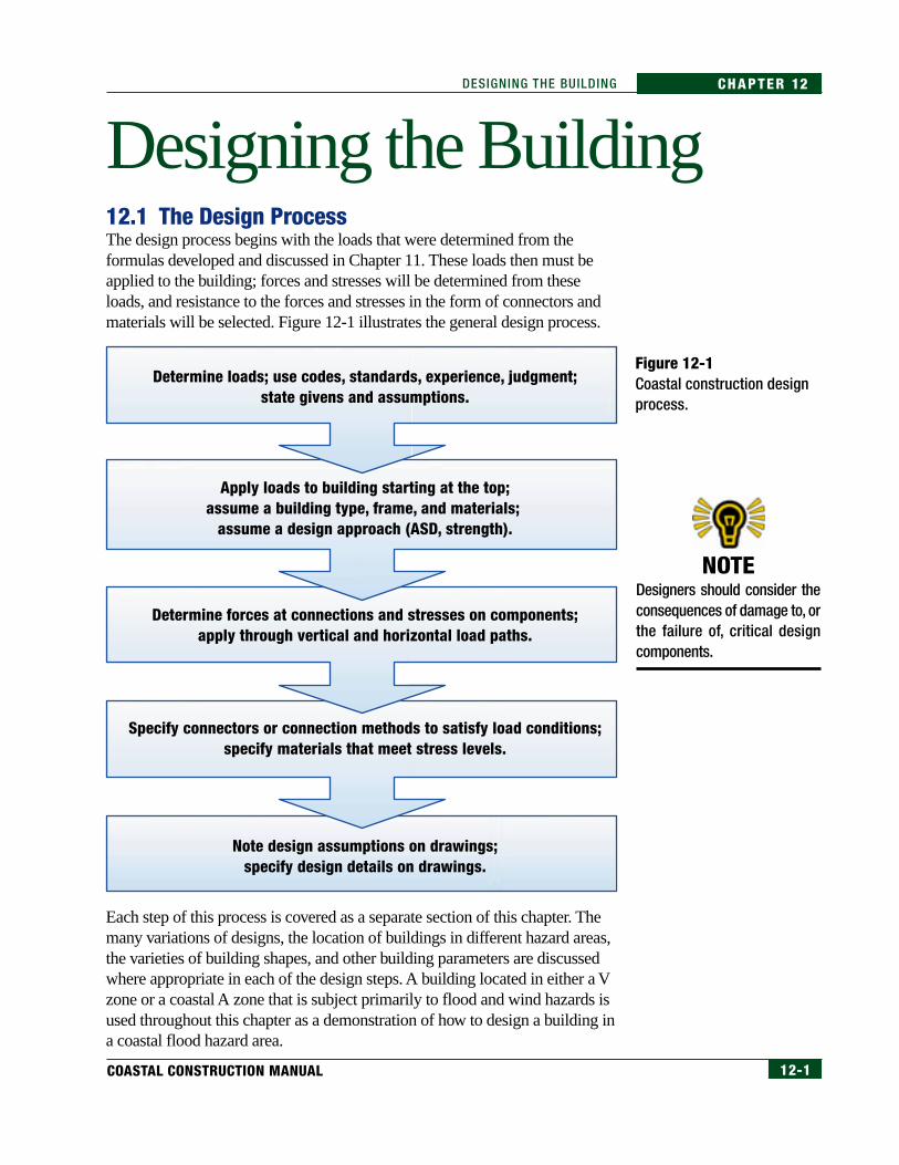
12.1 The Design ProcessThe design process begins with the loads that were determined from theformulas developed and discussed in Chapter 11. These loads then must beapplied to the building; forces and stresses will be determined from theseloads, and resistance to the forces and stresses in the form of connectors andmaterials will be selected. Figure 12-1 illustrates the general design process.
Each step of this process is covered as a separate section of this chapter. Themany variations of designs, the location of buildings in different hazard areas,the varieties of building shapes, and other building parameters are discussedwhere appropriate in each of the design steps. A building located in either a Vzone or a coastal A zone that is subject primarily to flood and wind hazards isused throughout this chapter as a demonstration of how to design a building ina coastal flood hazard area.
Determine loads; use codes, standards, experience, judgment;state givens and assumptions.
Determine forces at connections and stresses on components;apply through vertical and horizontal load paths.
Specify connectors or connection methods to satisfy load conditions;specify materials that meet stress levels.
Note design assumptions on drawings;specify design details on drawings.
Apply loads to building starting at the top;assume a building type, frame, and materials;
assume a design approach (ASD, strength).
Designing the Building
Figure 12-1Coastal construction designprocess.
NOTEDesigners should consider theconsequences of damage to, orthe failure of, critical designcomponents.

12-2 FEDERAL EMERGENCY MANAGEMENT AGENCY
CHAPTER 12 DESIGNING THE BUILDING
The design process involves the following:
• determining design loads
• determining the building’s foundation, structural frame, and envelope
• determining the connections between individual elements
• determining the elevation, placement, and support for utilities
• selecting the appropriate materials
The entire design process is based on the fundamental premise thatanticipated service and natural hazard loads can and must be transferredthrough the building in a continuous path to the supporting soils. ANYweakness in that continuous path is a potential point of failure of the building,and any failure creates the possibility for large property losses and thepotential for loss of life.
This manual does not cover all of the almost endless number of combinationsof loads, materials, building shapes and functions, hazard zones, andelevations. The designer will find that engineering judgment will need to beapplied to a range of problems during the design of a coastal residentialbuilding. Therefore, it is the intent of this manual to provide sufficientbackground and examples so that a designer can effectively design aresidential building for construction in a coastal hazard area.
In this manual, the recommended design method is Allowable Stress Design(ASD), so there are factors of safety (FS) built into the development of thematerial stresses and the forces at the connections. This design method hasbeen chosen for this manual because ASD continues to be the predominantdesign method in light-frame, residential, wood construction. Most suppliersof wood framing hardware and connectors provide load limits for theirproducts with factors of safety built into the limits. Load and Resistance FactorDesign (LRFD) guidance is available for wood if the designer prefers thisultimate strength or limit state design method.
12.2 Step 1 – Determining LoadsThe types of loads that most commonly act on one- to three-story residentialbuildings during severe natural hazard events are as follows:
• dead loads
• live loads
• flood loads
• wind loads
• earthquake (seismic) loads
• snow loads
CROSS-REFERENCEAllowable Stress Design (ASD)is described in Section 11.11.
NOTEASCE 7-98 addresses other loads(e.g., fluid, lateral earth pressure,rain) that may need to be con-sidered depending on the natureof the construction project.
12-3COASTAL CONSTRUCTION MANUAL
CHAPTER 12DESIGNING THE BUILDING
Additional loads caused by long-term and short-term erosion and localizedscour can play a significant part in the total loads that are imparted to thestructure; therefore these conditions must be accounted for.
Load determination involves calculating each type of load. The most severeload combination required by the applicable building code or standard is thenapplied to the structure. Therefore, consideration must be given to thefollowing loads and factors that affect loads:
Dead loads – The weight of the building and accessory equipment such astanks, piping, electrical service panels and conduits, and HVAC equipment.
Live loads – Combined loads of occupants, furnishings, and non-fixed equipment.
Flood loads – Flood depth and velocity, wave effects, expected long-term andshort-term erosion as well as localized scour, elevation of the building inrelationship to the expected flood conditions, and floating debris impacts.
Wind loads – Roof shape and pitch, siting, topography and exposure, andbuilding shape and orientation. The height of the structure also needs tobe assessed.
Seismic loads – Mass (including elevation, location, and distribution) of thebuilding, soil supporting the building, height of the building above the ground,and additional loads that the building may occasionally support (e.g., snow).
Snow loads – Roof shape and pitch, multi-level roofs, and buildingorientation. Also, drifting snow may cause unbalanced loading on theroof system.
An important part of design is deciding how these loads are imparted to thebuilding. This means that the designer must decide where (and perhaps inwhat sequence) the loads are to be applied to the building.
12.3 Step 2 – Applying Loads to the BuildingThe following concepts show how one design step leads to the next:
• All design loads create forces in and on the building. The forces aretransferred through load paths.
• Load paths always end in the soil that supports the structure.
• Loads should be applied to the building beginning at the top.
• Loads should be determined for both the vertical and horizontalload paths.

12-4 FEDERAL EMERGENCY MANAGEMENT AGENCY
CHAPTER 12 DESIGNING THE BUILDING
• Load transfer creates forces at connections and imparts stresses in thematerials. Connections and materials must be strong enough to handlethose forces and stresses.
• The load path must be continuous; any break or weakness in the loadpath “chain” can result in damage or even structural failure.
12.3.1 Failure ModesBuilding failures most frequently occur by one or more of the following:
Primary Failure Modes
Uplift: Vertical forces caused by wind or buoyancy exceed the weight of thestructure and the strength of the soil anchorage. The building fails by beinglifted off its foundation or because the foundation pulls out of the soil.
Overturning: The applied moments caused by wind, wave, earthquake, andbuoyancy forces exceed the resisting moments of the building’s weight andanchorage. The building fails by rotating off its foundation or because thefoundation rotates out of the soil.
Sliding or Shearing: Horizontal forces exceed the friction force or strengthof the foundation. The building fails by sliding off its foundation, by shearfailure of components transferring loads to its foundation, or by thefoundation sliding.
Secondary Failure Mode
Collapse: Collapse is a secondary mode of failure. Structural components failor become out of plumb or level under uplift, overturning, or sliding. Thebuilding then becomes unstable and collapses.
Buildings under extremely heavy vertical downward loads, such as snow, canalso fail in bending, shear, or compression of primary structural members. Forpurposes of this manual, it is assumed the designer is familiar with the designconcepts used to support these ordinary gravity loads.
12.3.1.1 UpliftUplift failure occurs when the vertical forces are greater than the weight of thebuilding, the strength of the structural frame (e.g., fasteners or connections),or the foundation anchorage. This type of failure can occur from high windsor buoyancy. Figure 12-2 illustrates how vertical uplift wind forces (F1– F 6 )from the roof areas shown in Figure 12-16 pull on the structural components.The forces are the products of the pressures shown in Table 11.7, in Chapter11, and the applicable area of the building.

12-5COASTAL CONSTRUCTION MANUAL
CHAPTER 12DESIGNING THE BUILDING
This manual will show how to calculate forces with the projected areamethod, which will simplify calculations. The horizontal projected area,shown above the buildings in Figure 12-2, is used for calculating uplift.The horizontal projected area for each roof segment must be multiplied bythe pressure per unit area for that segment and all of the forces summed toarrive at a total uplift force. This method is similarly applicable to otherfailure modes.
Figure 12-2Uplift.
Wind Direction
Uplift
Uplift
FloodDirection
Wind Direction
FloodDirection
HorizontalProjected
Area
HorizontalProjected
Area
LowestFloor
Expected Scour
ErodedGroundSurface
F3
F4
F5
F5
Wb
f f f f
f
f
F1
F6
F2
F2
LowestFloor
Expected Scour
ErodedGroundSurface
F3
F4
Wb
Ws
F1
F6
F = Wind ForceWb = Building Weight (Including Foundation)
Ws = Soil Weight and Frictionf = Frictional Resistance

12-6 FEDERAL EMERGENCY MANAGEMENT AGENCY
CHAPTER 12 DESIGNING THE BUILDING
Field investigations indicate that the failure of houses with wood-framed roofsoften occurs first at the roof, often at improper fastening between the roofsheathing and building frame. Proper fastening of the roof sheathing is alsoimportant because there is little dead load at the roof to resist uplift. Afterwind and/or rain has entered the building (in a hurricane or other storm event),forces on other building components increase and cause additional failure.
The progressive nature of failures is illustrated in Figure 12-3, in which thecollapsed trusses are an indication that, once the sheathing was removed, thetrusses lost the lateral support required for stability and for resistance to lateralwind forces.
The progressive nature of uplift failure is further demonstrated in Figure 12-4.The sheathing is missing at the right end of the structure, and several trussescollapsed because of the loss of lateral support otherwise provided by the roofsheathing. The roof damage allowed the wind to enter the structure and pullthe wall panel down. Obviously, when the structural failure progresses to thestage shown in this figure, significant interior damage comes from rainentering the building.
Note the eave overhang in Figure 12-4. Uplift failures frequently occur atwide overhangs. In addition to imposing uplift forces, or suction pressures, onthe roof surface itself, wind pushes up on the roof sheathing from underneaththe eaves or other overhangs. The combination of these forces can causeeither a failure in the roof sheathing or a failure in the connection between theroof framing and the exterior wall.
Figure 12-3Hurricane Andrew (1992),Dade County, Florida. Roofstructure failure due toinadequate bracing.

12-7COASTAL CONSTRUCTION MANUAL
CHAPTER 12DESIGNING THE BUILDING
Porch roofs are very susceptible to uplift failure. They generally have alarge surface area, are unprotected from the wind (and thus as openstructures experience higher wind pressures), are relatively light, and arenormally supported on widely spaced columns. The loss of the connectionbetween the roof and its support causes failures like that shown in Figure12-5. This figure demonstrates the importance of providing framingconnections that can resist uplift.
Figure 12-4Hurricane Andrew (1992),Dade County, Florida.Second-story wood framing(on first-story masonry). Endgable and wall failure.
Figure 12-5Hurricane Diana (1984). Upliftfailure of a porch roof.
Preventing wind from entering the building significantly reduces the potential foruplift failure and involves protecting the building envelope. Wind pressures on“partially enclosed” buildings are approximately 30 percent higher than windpressures on enclosed buildings—see Table 6-2 in ASCE 7-98 (ASCE 1998b).

12-8 FEDERAL EMERGENCY MANAGEMENT AGENCY
CHAPTER 12 DESIGNING THE BUILDING
The openings of the house in Figure 12-6 were protected, and only minimaldamage to the structure is evident in the photograph.
Failure from uplift can occur some distance inland from the coastline. Areasof Exposure D (ASCE 7-98 exposure classification) can extend 1,500 feetinland (approximately 1/4 mile). These areas include inland waterways, theGreat Lakes, and coastal areas of California, Oregon, Washington, andAlaska but exclude shorelines in hurricane-prone regions, which are now inExposure C. Design wind pressures in Exposure D are 18.5 percent higherthan those in Exposure C.
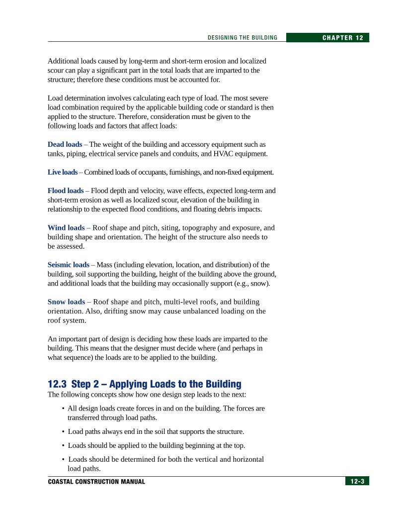
12.3.1.2 OverturningThe next possible failure mechanism is overturning. Overturning can occurwhen insufficient weight or anchorage exist to prevent the building fromrotating about a “pivot” point along one side of the building. Figure 12-7illustrates this failure mode. To prevent this failure, the resisting momentcapacity must be greater than the overturning moment. Moment, measured infoot-pounds (ft-lb), is the force times the distance (d) from the centroid ofapplied force to the pivot point. For the structure to be in equilibrium, the sumof the overturning moments must be less than the righting moment capacity.
In natural hazard events, overturning can occur from high-wind, seismic, orflood events. Floods can cause overturning if the building is below the floodlevel and inundated by moving water. Figure 12-8 shows a building that wasoverturned by flood and wind forces. The projected area method is again usedto determine the moments. In the design of an elevated building, the verticalprojected area is multiplied by the pressure per unit area for each roof andwall segment and then by the distance from the pivot point to the point at
Figure 12-6Hurricane Andrew (1992),Dade County, Florida.Openings in house protectedwith plywood panels.
12-9COASTAL CONSTRUCTION MANUAL
CHAPTER 12DESIGNING THE BUILDING
Figure 12-7Overturning.
f f f f f
f
Wind Direction
FloodDirection
Wind Direction
FloodDirection
Overturning
Overturning
HorizontalProjected
Area
HorizontalProjected
Area
LowestFloor
Expected Scour
ErodedGroundSurface
Pivot Point
Pivot Point
F3
F2
Wb
F8
F4
F6
F1
F1
F5
F2
F6
F5
F4
F7
Ff
F3
LowestFloor
Expected Scour
ErodedGroundSurface
Wb
F8F7
Ff
F = Wind Force
Ff = Flood Force
Wb = Building Weight (Including Foundation) Acts at Centroid
f = Frictional Resistance
VerticalProjected Area
VerticalProjected Area

12-10 FEDERAL EMERGENCY MANAGEMENT AGENCY
CHAPTER 12 DESIGNING THE BUILDING
which the force acts. The uplift force on the roof also causes the building toturn over about the pivot point and is included in the overturning momentequilibrium analysis.
For lightweight structures (e.g., manufactured homes, appurtenantstructures such as storage sheds, garages, outdoor pool enclosures, andgazebos), there is a high risk of overturning failure. Failure occurs in theanchorage of the building to the foundation or by the foundation rotatingout of the ground. Figure 12-9 shows a lightweight building (manufacturedhome) overturned by high winds.
Figure 12-8Hurricane Fran (1996), NorthCarolina. House overturnedby flood and wind forces.
Figure 12-9Hurricane Fran (1996), NorthCarolina. Lightweight building(manufactured home)overturned by wind forces.

12-11COASTAL CONSTRUCTION MANUAL
CHAPTER 12DESIGNING THE BUILDING
12.3.1.3 Sliding or ShearingIf the building adequately resists uplift and overturning, it can still fail in slidingor shearing. Sliding failure occurs where the building connects to the foundationor where the foundation “connects” to the supporting soil. Figure 12-10illustrates this failure mode.
Figure 12-10Sliding failure.
Wind Direction
FloodDirection
Wind Direction
Sliding
Sliding
FloodDirection
LowestFloor
LowestFloor
Expected Scour
ErodedGroundSurface
F3
F2
Wb
F8
F2
F7
F7
Ff
F3
Expected Scour
ErodedGroundSurface
f
f
Wb
F8
Wps
Ff
F = Wind Force
Ff = Flood Force
Wb = Building Weight (Including Foundation)
Wps= Passive Soil Pressure
f = Frictional Resistance
VerticalProjected Area
VerticalProjected Area

12-12 FEDERAL EMERGENCY MANAGEMENT AGENCY
CHAPTER 12 DESIGNING THE BUILDING
In pile-supported buildings, a more likely failure is excessive lateral movement,potentially resulting in building collapse. Resistance to shear is provided by thefoundation and eventually the soil.
During natural hazard events, sliding failures can occur when erosion andscour have removed soil needed to prevent sliding. Figure 12-11 shows howerosion and scour can affect a foundation’s ability to resist sliding.
Sliding failures can also occur when stiff foundation elements such asmasonry “shear off” or when flexible foundation elements such as wood pilessnap. Figure 12-12 shows piles snapped off.
Figure 12-11Hurricane Fran (1996), NorthCarolina. Failure of a coastalA-zone building constructedon a masonry wall and slab-on-grade foundation. Thefailure resulted fromundermining of thefoundation by severe scour.
Figure 12-12Hurricane Fran (1996), NorthCarolina. Building pilings(circled) snapped at top.

12-13COASTAL CONSTRUCTION MANUAL
CHAPTER 12DESIGNING THE BUILDING
Figure 12-13 shows an entire building that withstood uplift and overturningforces, but slid inland after the connection between the building and thefoundation failed.
The lateral resistance of the soil is a function of the internal friction of the soil.The frictional resistance of the soil is determined by Formula 12.1.
Sliding can also be resisted by passive soil pressure against a vertical surfaceof a belowgrade foundation.
12.3.1.4 CollapseWhen structural elements fail or lose alignment, other undamaged elementscan fail. In extreme cases, such failures can cause the building to collapse.Figure 12-14 shows several collapsed buildings near a temporary inlet cut byflood flows during Hurricane Fran. The water flowing through the new inletcaused the buildings to collapse.
Figure 12-13Hurricane Fran (1996), NorthCarolina. Building thatmoved off its foundation.Original location indicated byblack line. Note that theporch roof failed on thehouse on the left.
NOTEThe case study building shownin Chapter 11 to which flood,wind, and seismic loads wereapplied will be followed through-out this chapter.
Frictional Resistanceof Soil
Formula 12.1 Frictional Resistance of Soil
where: F = sliding resistance
φ = angle of internal friction of soil
F = (tan φ) (building weight)
(Angles of internal friction are available in numerous engineering texts.)

12-14 FEDERAL EMERGENCY MANAGEMENT AGENCY
CHAPTER 12 DESIGNING THE BUILDING
Now that the conditions under which light-frame buildings can and have failedhave been discussed, the concept of a continuous load path will be examined.
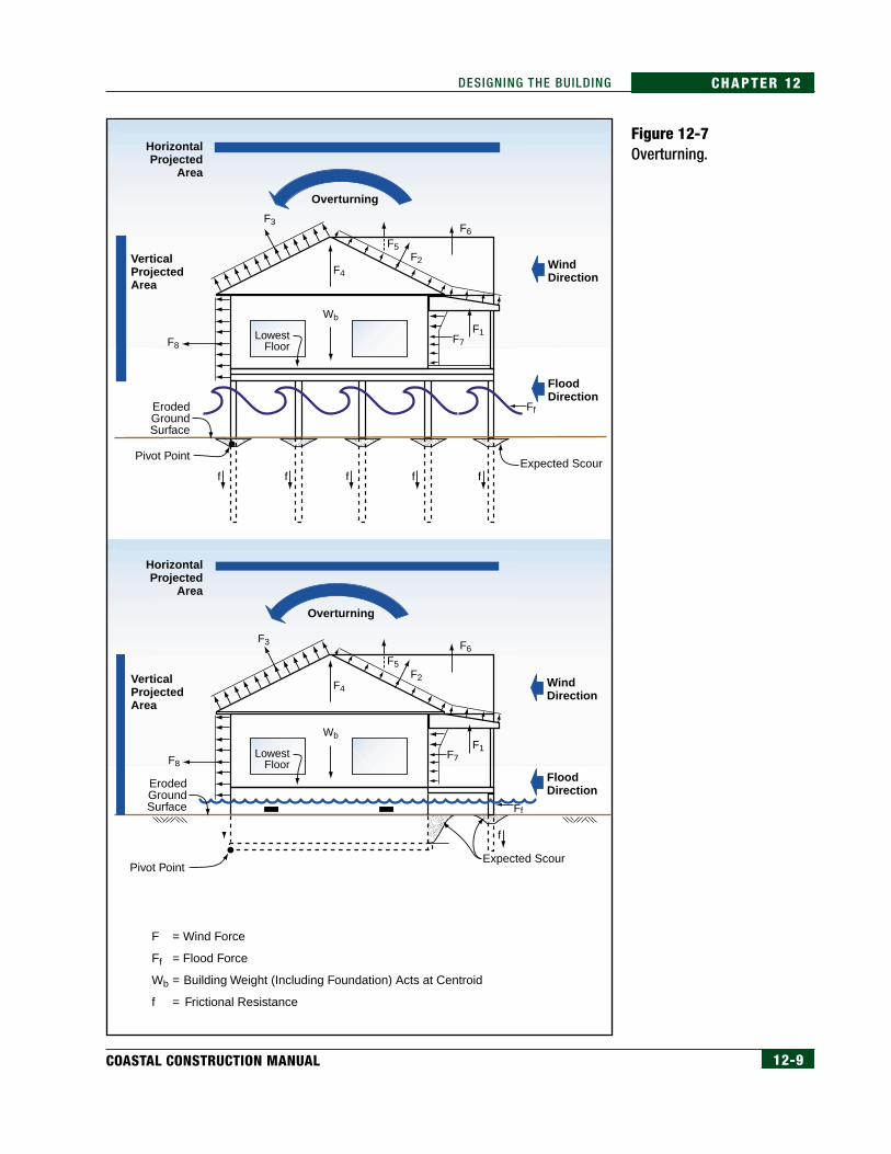
12.3.2 Load PathA load path can be thought of as a “chain” running through the building.Because all applied loads must be transferred to the foundation, the load pathchain must connect to the foundation. To be effective, each “link” in the chainmust be strong enough to transfer loads without breaking.
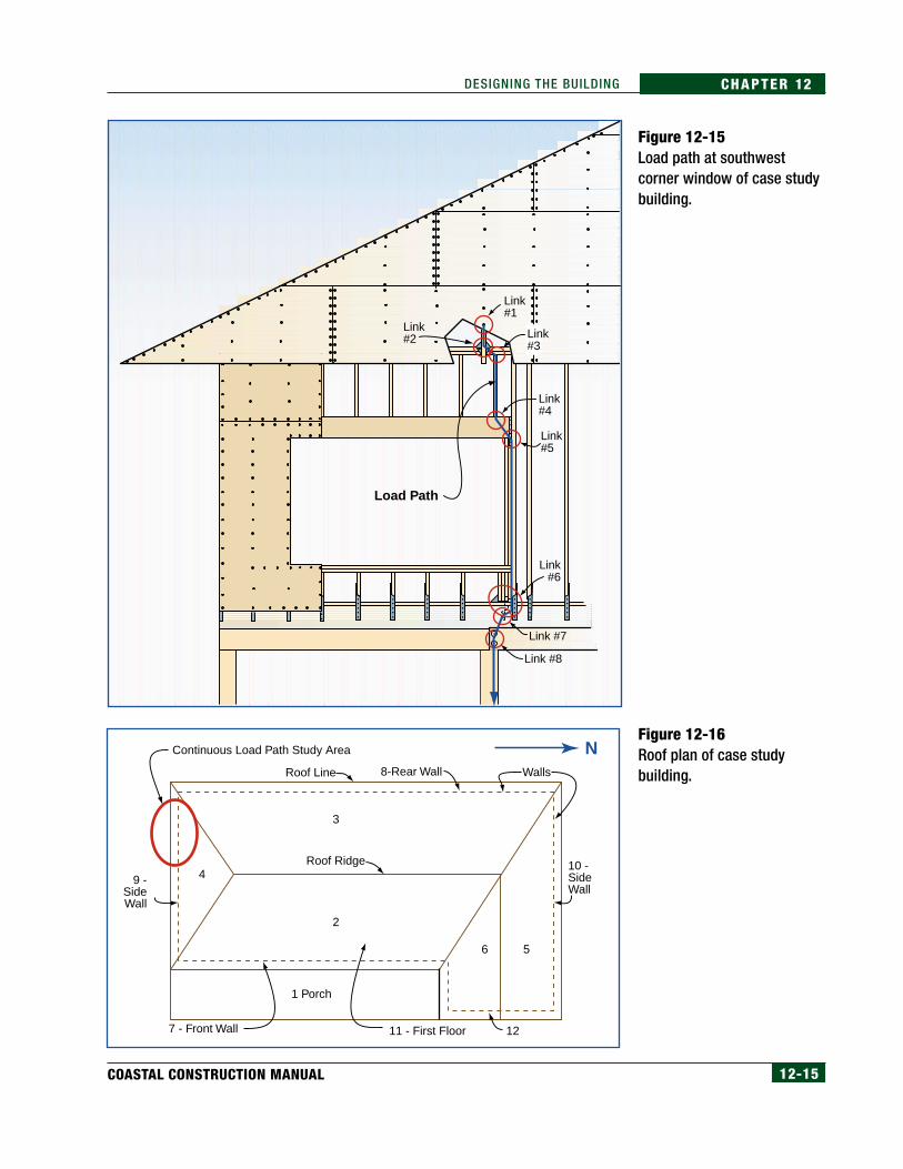
Figure 12-15 shows the load path and the links studied throughout thischapter. This load path was selected because it includes a hip roof, a windowopening, a shearwall, and a pile support. Figures 12-16 and 12-17 show roofplans and elevations of the case study building used to illustrate the load anddesign computations presented in Chapter 11 and in this chapter.
The design loads must be applied to each link to determine what loads exist.Each link can then be designed to prevent failure. This detailed study beginsin Section 12.4.
Figure 12-14Hurricane Fran (1996), NorthCarolina. Building collapsecaused by the force of waterflowing through an inletcreated across Topsail Islandduring the storm.
12-15COASTAL CONSTRUCTION MANUAL
CHAPTER 12DESIGNING THE BUILDING
Figure 12-15Load path at southwestcorner window of case studybuilding.
Figure 12-16Roof plan of case studybuilding.
Continuous Load Path Study Area
Roof Ridge
3
2
6 5
4
1 Porch
8-Rear Wall
10 -SideWall
Roof Line
9 -SideWall
7 - Front Wall 11 - First Floor 12
Walls
N
Link #8
Link #7
Load Path
Link#6
Link #5
Link #4
Link #3
Link #2
Link #1

12-16 FEDERAL EMERGENCY MANAGEMENT AGENCY
CHAPTER 12 DESIGNING THE BUILDING
12.3.3 Structural Building SystemsFour primary structural building systems are used in most residentialconstruction:
• platform framing
• balloon framing
• post-and-beam framing
• concrete/masonry
The structural system used for a building must either be known or assumedbefore the building can be analyzed.
12.3.3.1 Platform FramingAcross the United States, this is by far the most common method of framing awood-stud or steel-stud residential building. In the platform framing method,a floor assembly consisting of beams, joists, and a subfloor creates a“platform” that supports the exterior and interior walls. The walls are
Figure 12-17Elevations of case studybuilding.
Front Elevation
Side Elevation
Continuous LoadPath Study Area

12-17COASTAL CONSTRUCTION MANUAL
CHAPTER 12DESIGNING THE BUILDING
normally laid out and framed flat on top of the floor, tilted up into place,and attached at the bottom to the floor through the wall bottom plate. Thewalls are attached at the top to the next-level floor framing or (in a one-story building) to the roof framing. Figure 12-18 is an example ofplatform framing in a two-story building.
This method is commonly used on all types of foundation systems, includingwalls, piles, piers, and columns consisting of wood, masonry, and concretematerials. Some of the advantages and disadvantages of this framing methodare listed below.
Advantages
• Walls can be built on the floor and tilted into place.
• Lumber for standard-height walls can be purchased pre-cut.
• Fireblocking at floors is created at each floor line.
• Plumb walls are easy to build.
• The construction process is faster than in other framing methods.
Figure 12-18Example of two-story platform framing on a pile-and-beam foundation. (For clarity, drawing is notto scale.)
Double Top Plate
Bottom Plate
Double Top Plate
Bottom Plate
Band Board
Beam
Pile
Subfloor
Subfloor
12-18 FEDERAL EMERGENCY MANAGEMENT AGENCY
CHAPTER 12 DESIGNING THE BUILDING
Disadvantages
• Creates potential failure planes in the building at every wall/floor/roofjoint.
• Does not leave much chase space in exterior walls between floors.
• Makes proper detailing and construction of connections critical,because the building is constructed with a skeleton frame and isrelatively light,
Platform framing contains an inherent weakness in that a failure plane inshear is built into floor/wall and wall/gable roof connections as shown inFigure 12-18. The designer must design these connections so load isadequately transferred across these failure planes.
12.3.3.2 Balloon FramingThe balloon method uses continuous exterior wall studs that extend up fromthe foundation. The floor framing is supported on either blocking or a ribbonboard attached to the studs. This method offers some benefits over platformframing, but is more expensive. Figure 12-19 is an example of balloonframing in a two-story building.
Some of the advantages and disadvantages of this framing method are listed below.
Advantages
• Results in less vertical shrinkage than the platform framing method.
• Can be used in the top story of a gable end wall without undue costpremium.
• Reduces the number of load transfer connections and the possibility ofa failure plane from shear.
Disadvantages
• Requires splicing or scabbing of wall studs, because one-piece lumberlong enough to extend to the roof is not available.
• Costs more than platform framing.
• Firestopping is required at each floor level.
• Method is not as familiar to construction trades.
CROSS-REFERENCESee Figure 12-43 on page12-48 for the illustration of Link# 6, the wall to floor connection.

12-19COASTAL CONSTRUCTION MANUAL
CHAPTER 12DESIGNING THE BUILDING
Because it produces continuous exterior walls, balloon framing lacks thefailure planes inherent in the platform method and therefore produces a morerigid frame.
12.3.3.3 Post-and-Beam FramingThe post-and-beam method uses continuous posts installed as part of thefoundation system with support provided by beams that also support thefloors and roof. The posts and beams form the primary frame of the building.Exterior walls installed between the posts form the building enclosure. Figure12-20 is an example of post-and-beam framing in a two-story building.
Figure 12-19Two-story balloon framing on a pile-and-beamfoundation. (For clarity, drawing is not to scale.)
Rafter
Ceiling Joist
DoubleTop Plate
Continuous/SplicedStud Length
Ribbon Board
Firestopping
Typical Firestopping
Pile
Beam
Subfloor
Subfloor

12-20 FEDERAL EMERGENCY MANAGEMENT AGENCY
CHAPTER 12 DESIGNING THE BUILDING
Some of the advantages and disadvantages of this framing method arelisted below.
Advantages
• Offers a clearly defined and continuous load path for vertical loads.
• Allows the frame to be an extended portion of the foundation.
Disadvantages
• Costs more than other wood-frame methods.
• May make attachment of walls and portions of the building envelopemore difficult.
• Requires lumber of greater lengths and therefore limited availability.
The performance of the entire building, as in other framing methods, relies ongood connections between the structural frame and the exterior walls, theprimary failure plane in this type of frame.
Figure 12-20Typical post-and-beam framing. (For clarity, drawingis not to scale.)
Rafter
Ceiling Joist
Walls InstalledBetween Posts
Subfloor
Subfloor
Floor Beam
Continuous Post

12-21COASTAL CONSTRUCTION MANUAL
CHAPTER 12DESIGNING THE BUILDING
12.3.3.4 Concrete/MasonryIn certain parts of the United States, concrete/masonry building systemsare the prevalent construction method. When masonry is used as theexterior wall material, the walls are normally constructed to full height(similar to wood balloon framing) and then wood floors and the roof areframed into the masonry. Fully or partially reinforced and groutedmasonry is preferable in high wind areas and required in seismic hazardareas. Floor framing is normally supported by a ledger board fastened tothe masonry and the roof is anchored into the top course of masonry.Figure 12-21 is an example of masonry wall construction in a two-storybuilding. Some of the advantages and disadvantages of this method arelisted below.
Advantages:
• Results in continuous exterior walls and thus a stronger structuralframe.
• Results in exterior walls more resistant to windborne debris impacts.
• Results in exterior walls that require less maintenance.
• Provides greater fire resistance than wood.
In addition, reinforced masonry buildings have good high-winddamage history.
Disadvantages:
• Requires additional construction trades.
• Requires more construction time than wood framing.
• Requires special reinforcement in high-wind and seismic hazard areas.
• May require additional framing inside the exterior walls for interiorfinishes.
• Increases difficulty of insulation without additional interior wood walls.
• Requires more extensive foundation system, because of greater exteriorwall weight.

12-22 FEDERAL EMERGENCY MANAGEMENT AGENCY
CHAPTER 12 DESIGNING THE BUILDING
12.3.4 Construction MaterialsIn most coastal areas of the United States, wood is the primary material forcoastal construction. It is strong, lightweight, and easy to work with. Wood isavailable in standard dimension lumber as well as new engineered materialssuch as laminated beams and I-sections. Other materials are used forstructural systems, including reinforced concrete, light-gauge steel studs,reinforced masonry, and heavy steel framing.
Each material offers benefits and drawbacks. At this stage, the designer mustselect materials so that dead loads can be determined. The material selectionmust be based on cost, availability, and the ability to properly connectbuilding elements. Table 12.1 lists some of the wood products available in themarketplace for each of the major building components.
In most areas of the country, builders employ timesaving techniques such as theuse of pneumatic nailers. These “nail guns” typically use nails fastened togetherand produced in sleeves. Normally these nails differ slightly from common and
Figure 12-21Two-story masonry wall with wood floor androof framing.
NOTENational Evaluation ReportNER-272 (National EvaluationService, Inc. 1997) includesprescriptive nailing schedulesfor nails used in pneumatic nailguns. These nails are listed bylength and diameter.
Rafter
Ceiling Joist
Top Plate
Ledger Board
Wood Floor Joists
Concrete Slab
BondBeam
Bond Beam
Masonry Wall
Continuous Footing
Subfloor

12-23COASTAL CONSTRUCTION MANUAL
CHAPTER 12DESIGNING THE BUILDING
Table 12.1Wood Products Used forStructural Frame Components
box nails in length and/or diameter. Designers and builders are encouraged tospecify nailed connections by length and diameter of nail required instead ofthe more customary method of “pennyweight” or xd nail size.
A number of alternatives to wood are available for the components of thestructural frame (see Table 12.2).
12.3.5 Building Layouts and Architectural ShapesThe layout of the building plays the most significant role in the application ofloads to the building. Layout is a function of the following:
• number of stories
• orientation of the building in relation to the water or street (buildingaccess and view from the building)
• building shape
• openness of the floor plan
• cathedral ceilings or unusually high ceilings
• placement of building equipment, including mechanical systems,elevators, baths, and kitchens
• use of areas below the first floor
• use of outdoor areas such as decks, gazebos, and pools
• proximity to neighbors

12-24 FEDERAL EMERGENCY MANAGEMENT AGENCY
CHAPTER 12 DESIGNING THE BUILDING
The layout considerations that impact building design for natural hazardsinclude the following:
• Roof spans and shapes are influenced by building size, number andplacement of interior walls, and building height restrictions.
• Floor plan openness and space utilization affect the number andplacement of interior walls that may be needed for shearwalls.
• Equipment placement may affect building weight and placement ofsome framing members.
• Floor plans and building orientation dictate pile (foundation) layouts.
Table 12.2Alternatives to WoodProducts for StructuralFrame Components (NAHBResearch Center 1994)
NOTEThe application of some of thematerials listed in this table isgoverned by either standards orindustry-specific design and in-stallation guidance.
AlternativeBuilding
ComponentDefinition
Laminated Fiberboard Structural Sheathing
Light-Gauge Structural Steel
Structural Foam Sandwich Panels
Insulated Concrete Wall Forms
Insulated Concrete Wall System
Welded-Wire Sandwich Panels
Conventional Concrete Block
Insulated Concrete Block
Structural Lightweight Concrete
Wall sheathing
Floor, wall, and roof systems
Wall and roof systems
Wall systems
Wall systems
Wall and roof systems
Wall systems
Wall systems
Wall systems
Fibrous plys laminated under pressure and covered with foil or polyethylene
Galvanized steel framing components as a direct substitute for conventional wood framing systems
Structural panel consisting of two stiff skins separated by a foam core
Concrete cast between two foam panels or into the hollow cores of stackable, interlocking insulation blocks
Concrete cast over a polystyrene board in the center of conventional forms
Shotcrete applied over a steel-reinforced foam panel
Mixture of cement, aggregate, and water compacted and cured into blocks
Conventional block cores filled with either plastic inserts or foam insulation
Use of admixture and/or lightweight aggregates with conventional concrete
(Source: NAHB Research Center 1994)

12-25COASTAL CONSTRUCTION MANUAL
CHAPTER 12DESIGNING THE BUILDING
• Floor plans and space utilization dictate the orientation of floorsupport beams.
• Orientation and plan openness of the building affect the torsionalresponse to a seismic event.
• Building orientation, plan openness, and space utilization all affect thenumber and placement of openings such as windows and doors.
Table 12.3 lists some of the impacts that these layout considerations have ondesign issues that will affect the building’s performance during a naturalhazard event.
Table 12.3Building Layout and Impactson Natural Hazard Design
12.4 Step 3 – Determine Forces at Connections andStresses in Materials
Each link in the load path will now be examined to see how loads are appliedto each link and, thus, how designs for buildings are developed. Thisexamination will be done using the case study example of a building subjectto flood and high-wind hazards. Emphasis will be placed on those links wherefailures have typically occurred; however, under large forces caused bynatural hazards, failure will occur at the weakest link so that improvingperformance at historically weakest links may create a failure at another link.
12.4.1 Getting StartedThe first step is to determine the appropriate building areas and select thedesign constraints for the building so that when it is time to perform ananalysis of a particular connection, the basic information has already beendeveloped. Loads and pressures developed in the example problems inChapter 11 will be used in the analysis of forces and stresses at the links.Figures 12-15, 12-16, and 12-17 show the case study building and thelocation of the continuous load path to be studied. This analysis is for only
Impact onSeismic Design
Impact onWind Design
Impact onFlood Design
LayoutConsideration
Floor space
Number of stories
Building orientation
Plan openness
Design of area below first floor
Building equipment
Use of outdoor space
12-26 FEDERAL EMERGENCY MANAGEMENT AGENCY
CHAPTER 12 DESIGNING THE BUILDING
one of many load paths in the building. The selected load path isrepresentative of all of the loads that need to be analyzed for the south wall.For the analysis for this building complete, other load paths would need to bedetermined and other wind directions analyzed.
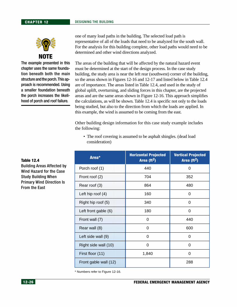
The areas of the building that will be affected by the natural hazard eventmust be determined at the start of the design process. In the case studybuilding, the study area is near the left rear (southwest) corner of the building,so the areas shown in Figures 12-16 and 12-17 and listed below in Table 12.4are of importance. The areas listed in Table 12.4, and used in the study ofglobal uplift, overturning, and sliding forces in this chapter, are the projectedareas and are the same areas shown in Figure 12-16. This approach simplifiesthe calculations, as will be shown. Table 12.4 is specific not only to the loadsbeing studied, but also to the direction from which the loads are applied. Inthis example, the wind is assumed to be coming from the east.
Other building design information for this case study example includesthe following:
• The roof covering is assumed to be asphalt shingles. (dead loadconsideration)
Table 12.4Building Areas Affected byWind Hazard for the CaseStudy Building WhenPrimary Wind Direction IsFrom the East
NOTEThe example presented in thischapter uses the same founda-tion beneath both the mainstructure and the porch. This ap-proach is recommended. Usinga smaller foundation beneaththe porch increases the likeli-hood of porch and roof failure.
Area*Horizontal Projected
Area (ft2)Vertical Projected
Area (ft2)
Porch roof (1)
Front roof (2)
Rear roof (3)
Left hip roof (4)
Right hip roof (5)
Left front gable (6)
Front wall (7)
Rear wall (8)
Left side wall (9)
Right side wall (10)
First floor (11)
Front gable wall (12)
440
704
864
160
340
180
0
0
0
0
1,840
0
352
480
0
0
0
440
600
0
0
0
288
* Numbers refer to Figure 12-16.

12-27COASTAL CONSTRUCTION MANUAL
CHAPTER 12DESIGNING THE BUILDING
• The siding is assumed to be lightweight (e.g., vinyl or wood) withstructural sheathing beneath. (dead load consideration)
• The structural frame of the building is wood. The roof and floorframing could be trusses or composite framing members such asplywood web roof rafters or floor beams. (dead load consideration)
• All openings are assumed to be protected from breakage or windpenetration; therefore, the building is considered enclosed. (windpressure consideration)
• The design wind speed is 120 mph, 3-sec peak gust (the equivalentfastest-mile wind speed is approximately 100 mph). (wind pressureconsideration)
• The BFE is 14.0 feet National Geodetic Vertical Datum (NGVD). Afreeboard of 1.0 foot is required. (flood load consideration)
• The eroded ground surface elevation is 5.5 feet NGVD, not including1.8 feet of local scour, which results in a ground elevation of 3.7 feetNGVD adjacent to the piles. (scour effect consideration)
• The soil is medium sand with a submerged unit weight of γ = 65 lb/ft3.(foundation reaction consideration)
The first step is to perform a global check of the uplift, overturning, andsliding or shearing forces described in Section 12.3.1.
12.4.1.1 UpliftThe vertical components of all forces are shown in Figure 12-22.
WARNINGThe assumption that the open-ings are protected is very impor-tant. If openings are not pro-tected, the forces must be de-termined assuming a partiallyenclosed building.
Figure 12-22Uplift and gravity forces onthe case study building.
NOTEThe uplift forces shown in Fig-ure 12-22 are equal to the hori-zontal projected areas fromTable 12.4 multiplied by the cor-responding wind pressuresshown in Table 11.7 for the eastwind direction.
Wind Direction
4,930 lb
17,289 lb
4,382 lb19,998 lb
3,520 lb90,439 lb
9,313 lb
8,892 lb

12-28 FEDERAL EMERGENCY MANAGEMENT AGENCY
CHAPTER 12 DESIGNING THE BUILDING
Calculate the uplift using the building areas from Table 12.4 and the pressures(p) from Table 11.7 (page 11-46). The sum of the uplift forces minus thebuilding weight and pile uplift capacity must be less than or equal to zero (withup being the positive sign convention) in order for the building to remain inplace without vertical displacement. The dead weight of the building is takenfrom standard unit weights and is shown as Calculation 12.1. It is assumed thatuplift from wind pushing up on the underside of the pile-supported house andsuction of the underside down towards the ground will not occur and thus willnot affect the building behavior in uplift.
Weight of this case study house on pile foundation (main house only, porchdetermined separately):
Roof = (10 lb/ft2)(2,248 ft2) = 22,480 lb
Exterior walls = (10 lb/ft2)(2,088 ft2) = 20,880 lb
Floor = (10 lb/ft2)(1,840 ft2) = 18,400 lb
Interior walls = (8 lb/ft2)(2,000 ft2 – assumed) =16,000 lb
Piles = (409 lb/each)(31 piles) = 12,679 lb
TOTAL WEIGHT = 90,439 lb
The front porch roof weighs (8 lb/ft2)(440 ft2) = 3,520 lb
Formula 12.2 shows how to determine the net uplift force in terms of thebuilding components and uplift pressures. This formula is used to determineoverall building stability.
The application of Formula 12.2 is illustrated below with the wind pressuresdetermined in the Wind Load Example Problem on page 11-45, the buildingareas shown in Table 12.4, and the uplift force diagram in Figure 12-2. SeeFigure 12-22 for the vertical components of the forces shown below.
Net uplift force = F1 + F2 + F3 + F4 + F5 + F6 –weight of building(0.6) – weight of porch roof(0.6)
Net uplift force (lb) = 19,998 + 8,892 + 9,313 +4,930 + 4,382 + 14,243 – (90,439)(0.6)–(3,520)(0.6)
Uplift = 64,804 – 56,375 lb = -8,429 lb
NOTELoad combination no. 4 in ASCE7-98 is the most stringent inthis case of uplift; it requiresthat the dead load be reducedby a factor of 0.6.
[12.1]
[12.2]
NOTEDesigners should determineactual dead loads from build-ing components.
Net Uplift Force
Formula 12.2 Net Uplift Force
Net Uplift Force = (building component projectedhorizontal area) (uplift wind pressure) – dead weight of building
12-29COASTAL CONSTRUCTION MANUAL
CHAPTER 12DESIGNING THE BUILDING
[12.3]
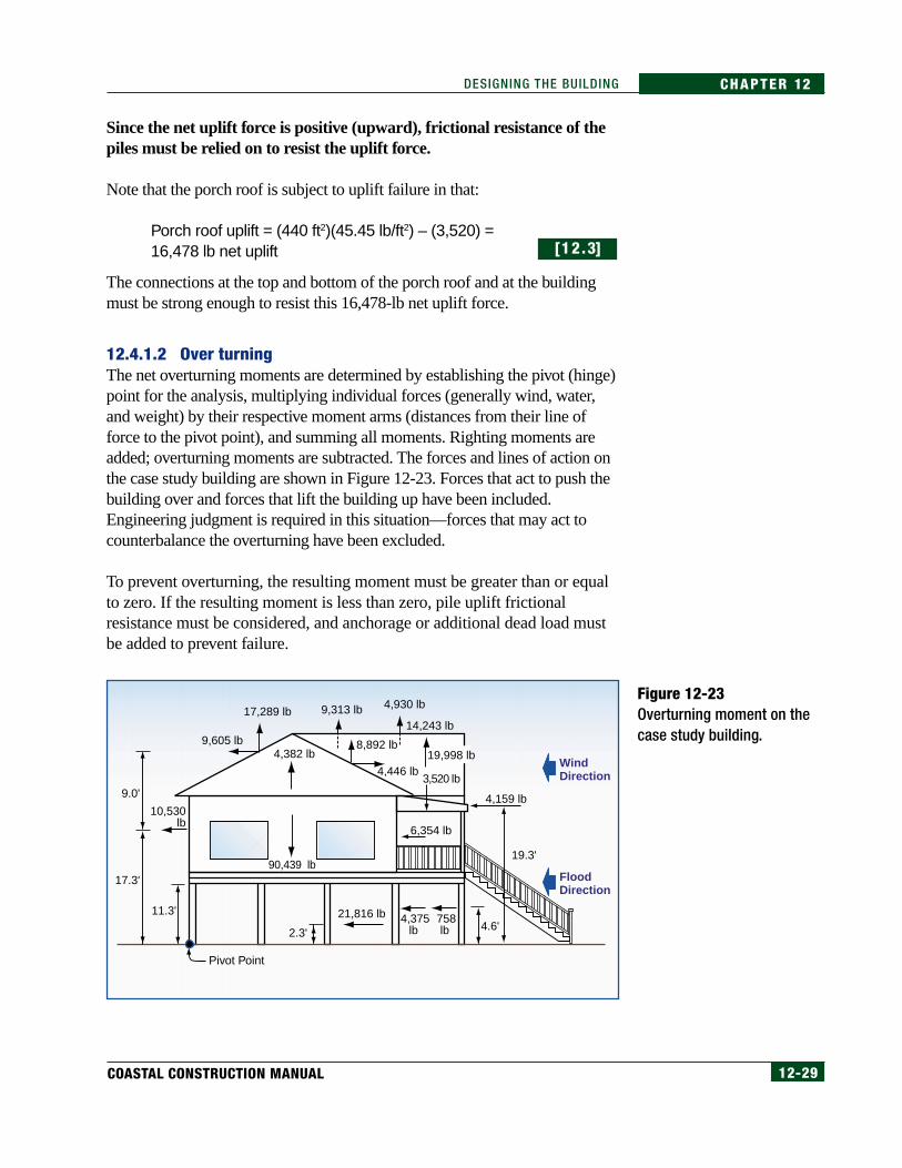
Figure 12-23Overturning moment on thecase study building.
Since the net uplift force is positive (upward), frictional resistance of thepiles must be relied on to resist the uplift force.
Note that the porch roof is subject to uplift failure in that:
Porch roof uplift = (440 ft2)(45.45 lb/ft2) – (3,520) =16,478 lb net uplift
The connections at the top and bottom of the porch roof and at the buildingmust be strong enough to resist this 16,478-lb net uplift force.
12.4.1.2 Over turningThe net overturning moments are determined by establishing the pivot (hinge)point for the analysis, multiplying individual forces (generally wind, water,and weight) by their respective moment arms (distances from their line offorce to the pivot point), and summing all moments. Righting moments areadded; overturning moments are subtracted. The forces and lines of action onthe case study building are shown in Figure 12-23. Forces that act to push thebuilding over and forces that lift the building up have been included.Engineering judgment is required in this situation—forces that may act tocounterbalance the overturning have been excluded.
To prevent overturning, the resulting moment must be greater than or equalto zero. If the resulting moment is less than zero, pile uplift frictionalresistance must be considered, and anchorage or additional dead load mustbe added to prevent failure.
Wind Direction
FloodDirection
3,520 lb
4.6'2.3'
9,605 lb
17,289 lb 9,313 lb 4,930 lb
14,243 lb
19,998 lb4,446 lb
10,530lb
17.3'
9.0'
19.3'
11.3'
Pivot Point
4,375lb
21,816 lb 758lb
6,354 lb
4,159 lb
90,439 lb
4,382 lb8,892 lb
12-30 FEDERAL EMERGENCY MANAGEMENT AGENCY
CHAPTER 12 DESIGNING THE BUILDING
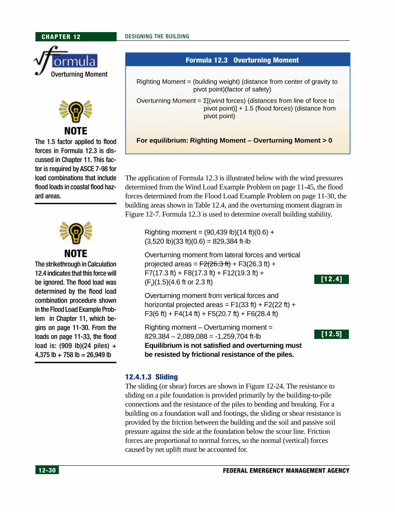
The application of Formula 12.3 is illustrated below with the wind pressuresdetermined from the Wind Load Example Problem on page 11-45, the floodforces determined from the Flood Load Example Problem on page 11-30, thebuilding areas shown in Table 12.4, and the overturning moment diagram inFigure 12-7. Formula 12.3 is used to determine overall building stability.
Righting moment = (90,439 lb)(14 ft)(0.6) +(3,520 lb)(33 ft)(0.6) = 829,384 ft-lb
Overturning moment from lateral forces and verticalprojected areas = F2(26.3 ft) + F3(26.3 ft) +F7(17.3 ft) + F8(17.3 ft) + F12(19.3 ft) +(Ff)(1.5)(4.6 ft or 2.3 ft)
Overturning moment from vertical forces andhorizontal projected areas = F1(33 ft) + F2(22 ft) +F3(6 ft) + F4(14 ft) + F5(20.7 ft) + F6(28.4 ft)
Righting moment – Overturning moment =829,384 – 2,089,088 = -1,259,704 ft-lbEquilibrium is not satisfied and overturning mustbe resisted by frictional resistance of the piles.
12.4.1.3 SlidingThe sliding (or shear) forces are shown in Figure 12-24. The resistance tosliding on a pile foundation is provided primarily by the building-to-pileconnections and the resistance of the piles to bending and breaking. For abuilding on a foundation wall and footings, the sliding or shear resistance isprovided by the friction between the building and the soil and passive soilpressure against the side at the foundation below the scour line. Frictionforces are proportional to normal forces, so the normal (vertical) forcescaused by net uplift must be accounted for.
[12.4]
[12.5]
NOTEThe 1.5 factor applied to floodforces in Formula 12.3 is dis-cussed in Chapter 11. This fac-tor is required by ASCE 7-98 forload combinations that includeflood loads in coastal flood haz-ard areas.
NOTEThe strikethrough in Calculation12.4 indicates that this force willbe ignored. The flood load wasdetermined by the flood loadcombination procedure shownin the Flood Load Example Prob-lem in Chapter 11, which be-gins on page 11-30. From theloads on page 11-33, the floodload is: (909 lb)(24 piles) +4,375 lb + 758 lb = 26,949 lb
Overturning Moment
Formula 12.3 Overturning Moment
Righting Moment = (building weight) (distance from center of gravity to pivot point)(factor of safety)
Overturning Moment = Σ[(wind forces) (distances from line of force to pivot point)] + 1.5 (flood forces) (distance from pivot point)
For equilibrium: Righting Moment – Overturning Moment > 0

12-31COASTAL CONSTRUCTION MANUAL
CHAPTER 12DESIGNING THE BUILDING
The sliding forces are determined by adding the horizontal wind and floodforces multiplied by the appropriate load combination factors. Wind forcesshould be applied to the projected vertical roof area that is perpendicular tothe wind flow direction to determine the horizontal sliding forces. Thedetermination of sliding forces in this case study will use the wind pressuresdetermined in the Wind Load Example Problem in Chapter 11 (page 11-45),the building areas shown in Table 12.4, and the sliding force diagram inFigure 12-10. Because the flood forces act at a point below the first floor line,sliding forces must be determined at the floor-to-pile connection and at thepile-ground intersection.
Sliding forces at floor-to-pile connection =F3 + F7 + F8 + F12 – F2
Sliding forces at floor-to-pile connection for each of31 piles = 9,605 + 6,354 + 10,530 + 4,159 – 4,446 =30,648 lb or989 lb/pile
Sliding forces at the pile/ground intersection = (windload calculated in Calculation 12.6) + (flood load of26,949 lb)(1.5)
Sliding forces at the pile/ground intersection foreach of 31 piles = 30,648 + 40,423 = 71,071 lb or2,293 lb/pile
Figure 12-24Sliding forces on the casestudy building. Engineeringjudgment is required in thissituation—wind forcesopposite the sliding directionare assumed to notsignificantly resist thissliding action.
[12.6]
[12.7]
NOTEThe information on the force ateach floor-to-pile connectionwill be used in Section 12.4 inanalyzing the building-to-pileconnection.
Wind Direction
FloodDirection
10,530lb
9.605 lb 4,446 lb
26,949 lb
6,354 lb
4,159 lb
12-32 FEDERAL EMERGENCY MANAGEMENT AGENCY
CHAPTER 12 DESIGNING THE BUILDING
If the case study building was installed on a foundation wall and footing, thesliding resistance of the soil could be determined with Formula 12.4:
12.4.2 Analyze Load Path LinksThe concept of load path links is discussed throughout this chapter. In thissection, individual links in a sample load path will be analyzed (see Figure 12-15). At each link, the maximum forces must be determined so that the buildingcan be adequately designed and detailed. As mentioned previously, links havebeen selected for the analysis of areas that historically have a high incidence offailure. Other critical links exist that will need to be analyzed. In addition toanalyzing individual links, this section investigates related structural elements.
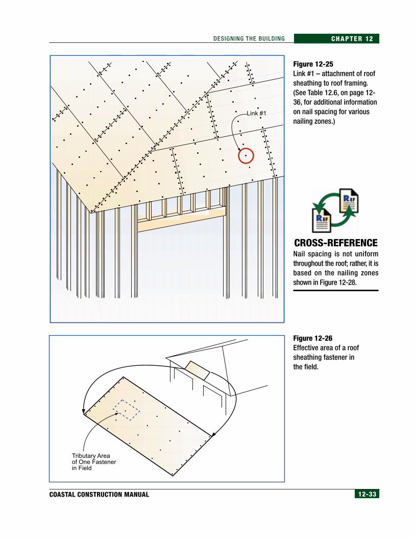
Link #1 – Roof Sheathing to Roof FramingThis link, shown in Figure 12-25, connects the roof sheathing to the roofframing. The connection can fail in withdrawal, shear, or by the sheathing“pulling over” the fastener. The roof sheathing is considered part ofComponents and Cladding in ASCE 7-98; therefore, pressure coefficientsare higher than those for similar areas of the Main Wind Force ResistingSystem (MWFRS).
Withdrawal:
From the Wind Load Example Problem in Chapter 11 (page 11-47), thepressure p is -87.42 lb/ft2 on this connection (hip roof overhang edge), which isthe uplift pressure for components and cladding, as roof sheathing is consideredcladding. Link #1 is a field nail in the sheathing; from ASCE 7-98, the effectivewind area for this cladding fastener is reduced to 10 ft2, but for this overhangcondition, the pressure p remains the same –87.42 lb/ft2. This pressure actsnormal to the roof surface, and it acts on the fastener through the effective area.
Figure 12-26 shows the effective area for the roof sheathing field fasteners.The width of the effective area is the spacing of the roof framing members.The actual area in which the wind uplift acts on the fasteners is the tributaryarea, which is the nail spacing times the spacing of the roof framing members.
NOTELoad paths for roof framing in-clude the connection betweenthe roof rafter and the ridgeboard. The ridge board must betreated as a beam when it issubject to upward bending fromuplift forces unless ridge strapsare installed across the ridgeboard to resist withdrawal of theboard from the ridge.
CROSS-REFERENCESee Section 12.5 for a discus-sion of the actual connection ateach link.
Sliding Resistance ofFoundation Walls andFooting
Formula 12.4Sliding Resistance of Foundation Walls and Footing
where: φ = internal angle of soil friction
N = net normal force (building weight – uplift forces)
Sliding Resistance = (tan φ)(N) + Passive Forceat Vertical Foundation Walls
12-33COASTAL CONSTRUCTION MANUAL
CHAPTER 12DESIGNING THE BUILDING
Figure 12-25Link #1 – attachment of roofsheathing to roof framing.(See Table 12.6, on page 12-36, for additional informationon nail spacing for variousnailing zones.)
Figure 12-26Effective area of a roofsheathing fastener inthe field.
CROSS-REFERENCENail spacing is not uniformthroughout the roof; rather, it isbased on the nailing zonesshown in Figure 12-28.
Tributary Areaof One Fastenerin Field
12-34 FEDERAL EMERGENCY MANAGEMENT AGENCY
CHAPTER 12 DESIGNING THE BUILDING
Nails must be spaced close enough to prevent withdrawal. Nail spacingdepends on the following:
• nail withdrawal value
• effective area
• uplift pressure
Nail withdrawal values depend on the following:
• specific gravity of the framing lumber
• depth of nail penetration into the roof framing member
• nail diameter
• nail shank characteristics (e.g., smooth, screw, ring-shank)
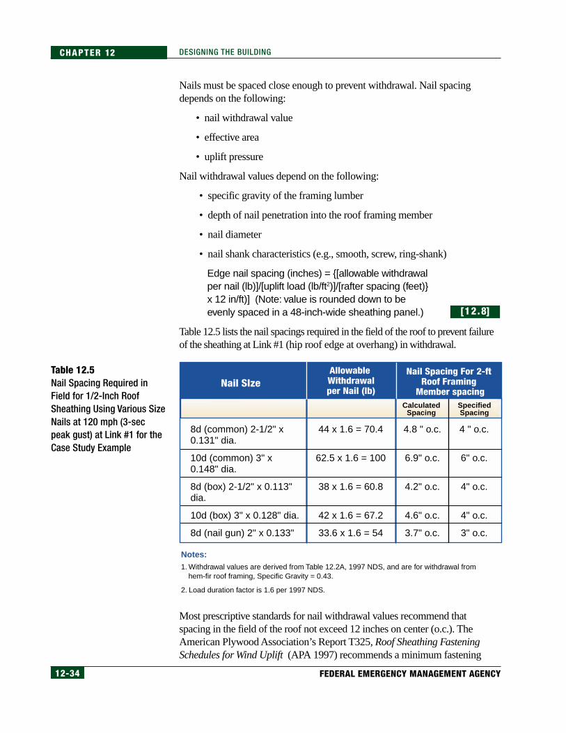
Edge nail spacing (inches) = {[allowable withdrawalper nail (lb)]/[uplift load (lb/ft2)]/[rafter spacing (feet)}x 12 in/ft)] (Note: value is rounded down to beevenly spaced in a 48-inch-wide sheathing panel.)
Table 12.5 lists the nail spacings required in the field of the roof to prevent failureof the sheathing at Link #1 (hip roof edge at overhang) in withdrawal.
Most prescriptive standards for nail withdrawal values recommend thatspacing in the field of the roof not exceed 12 inches on center (o.c.). TheAmerican Plywood Association’s Report T325, Roof Sheathing FasteningSchedules for Wind Uplift (APA 1997) recommends a minimum fastening
[12.8]
Table 12.5Nail Spacing Required inField for 1/2-Inch RoofSheathing Using Various SizeNails at 120 mph (3-secpeak gust) at Link #1 for theCase Study Example
Nail SIzeNail Spacing For 2-ft
Roof Framing Member spacing
Allowable Withdrawalper Nail (lb)
8d (common) 2-1/2" x 0.131" dia.
10d (common) 3" x 0.148" dia.
8d (box) 2-1/2" x 0.113" dia.
10d (box) 3" x 0.128" dia.
8d (nail gun) 2" x 0.133"
44 x 1.6 = 70.4
62.5 x 1.6 = 100
38 x 1.6 = 60.8
42 x 1.6 = 67.2
33.6 x 1.6 = 54
4.8 " o.c.
6.9" o.c.
4.2" o.c.
4.6" o.c.
3.7" o.c.
4 " o.c.
6" o.c.
4" o.c.
4" o.c.
3" o.c.
Notes:1. Withdrawal values are derived from Table 12.2A, 1997 NDS, and are for withdrawal from
hem-fir roof framing, Specific Gravity = 0.43.
2. Load duration factor is 1.6 per 1997 NDS.
CalculatedSpacing
SpecifiedSpacing

12-35COASTAL CONSTRUCTION MANUAL
CHAPTER 12DESIGNING THE BUILDING
schedule of 6 inches o.c. at the panel edges and 12 inches o.c. in the field. Toillustrate forces on roof sheathing, a finite element analysis of a 4-foot x 8-footroof panel included in the APA report showed that there were two criticalfasteners in the field when one fastener is either missing or ineffective. Thissheathing deflection model and the critical fasteners are shown in Figure 12-27. Uplift resistance of roof sheathing is also a function of support at paneledges (blocked or unblocked). Designers should consider specifying blockedpanel edges to increase uplift resistance.
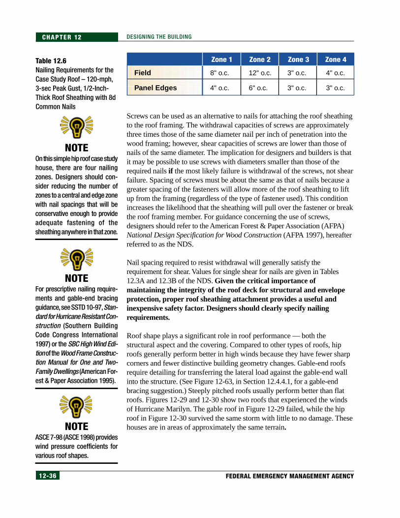
Using the uplift pressures from the Wind Load Example Problem (page11-45), Figure 12-28 shows the nailing zones for roof sheathing on a buildingin a 120-mph, 3-sec peak gust wind area. Table 12.6 lists the nailingrequirements for each zone. Nail spacings are rounded to the nearest 2 inchesfor convenience.
Figure 12-27Deflection of an unblockededge sheathing panel withone missing field nail due towind uplift loading (deflectedshape scaled forperspective). The missing (orotherwise ineffective)fastener in the field has asignificant impact on upliftresistance. Fastenerlocations made critical bythe missing nail are circled.
Figure 12-28Nailing zones for roofsheathing in 120-mphpeak gust wind zone forthe case study building(see Table 12.6).
Missing orIneffective
Fastener
3
3
3
3
4
4
1
1
1
1
1
1
2
2
2
2
2
12-36 FEDERAL EMERGENCY MANAGEMENT AGENCY
CHAPTER 12 DESIGNING THE BUILDING
Screws can be used as an alternative to nails for attaching the roof sheathingto the roof framing. The withdrawal capacities of screws are approximatelythree times those of the same diameter nail per inch of penetration into thewood framing; however, shear capacities of screws are lower than those ofnails of the same diameter. The implication for designers and builders is thatit may be possible to use screws with diameters smaller than those of therequired nails if the most likely failure is withdrawal of the screws, not shearfailure. Spacing of screws must be about the same as that of nails because agreater spacing of the fasteners will allow more of the roof sheathing to liftup from the framing (regardless of the type of fastener used). This conditionincreases the likelihood that the sheathing will pull over the fastener or breakthe roof framing member. For guidance concerning the use of screws,designers should refer to the American Forest & Paper Association (AFPA)National Design Specification for Wood Construction (AFPA 1997), hereafterreferred to as the NDS.
Nail spacing required to resist withdrawal will generally satisfy therequirement for shear. Values for single shear for nails are given in Tables12.3A and 12.3B of the NDS. Given the critical importance ofmaintaining the integrity of the roof deck for structural and envelopeprotection, proper roof sheathing attachment provides a useful andinexpensive safety factor. Designers should clearly specify nailingrequirements.
Roof shape plays a significant role in roof performance — both thestructural aspect and the covering. Compared to other types of roofs, hiproofs generally perform better in high winds because they have fewer sharpcorners and fewer distinctive building geometry changes. Gable-end roofsrequire detailing for transferring the lateral load against the gable-end wallinto the structure. (See Figure 12-63, in Section 12.4.4.1, for a gable-endbracing suggestion.) Steeply pitched roofs usually perform better than flatroofs. Figures 12-29 and 12-30 show two roofs that experienced the windsof Hurricane Marilyn. The gable roof in Figure 12-29 failed, while the hiproof in Figure 12-30 survived the same storm with little to no damage. Thesehouses are in areas of approximately the same terrain.
Table 12.6Nailing Requirements for theCase Study Roof – 120-mph,3-sec Peak Gust, 1/2-Inch-Thick Roof Sheathing with 8dCommon Nails
NOTEOn this simple hip roof case studyhouse, there are four nailingzones. Designers should con-sider reducing the number ofzones to a central and edge zonewith nail spacings that will beconservative enough to provideadequate fastening of thesheathing anywhere in that zone.
NOTEFor prescriptive nailing require-ments and gable-end bracingguidance, see SSTD 10-97, Stan-dard for Hurricane Resistant Con-struction (Southern BuildingCode Congress International1997) or the SBC High Wind Edi-tion of the Wood Frame Construc-tion Manual for One and Two-Family Dwellings (American For-est & Paper Association 1995).
NOTEASCE 7-98 (ASCE 1998) provideswind pressure coefficients forvarious roof shapes.
Zone 4Zone 3Zone 2Zone 1
Field
Panel Edges
8" o.c.
4" o.c.
12" o.c.
6" o.c.
3" o.c.
3" o.c.
4" o.c.
3" o.c.

12-37COASTAL CONSTRUCTION MANUAL
CHAPTER 12DESIGNING THE BUILDING
Figure 12-29Hurricane Marilyn (1995),U.S. Virgin Islands. Gable-endfailure caused by high winds.
Figure 12-30Hurricane Marilyn (1995),U.S. Virgin Islands. Hip roofthat survived high winds withlittle to no damage.
12-38 FEDERAL EMERGENCY MANAGEMENT AGENCY
CHAPTER 12 DESIGNING THE BUILDING
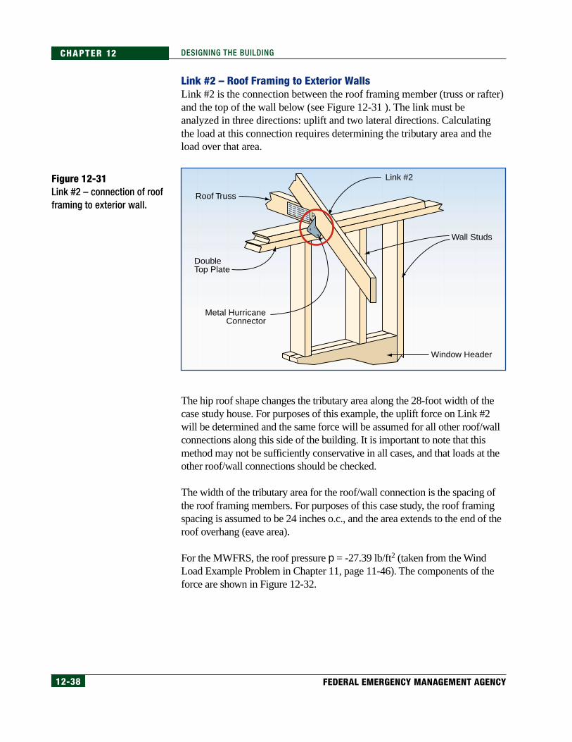
Link #2 – Roof Framing to Exterior WallsLink #2 is the connection between the roof framing member (truss or rafter)and the top of the wall below (see Figure 12-31 ). The link must beanalyzed in three directions: uplift and two lateral directions. Calculatingthe load at this connection requires determining the tributary area and theload over that area.
The hip roof shape changes the tributary area along the 28-foot width of thecase study house. For purposes of this example, the uplift force on Link #2will be determined and the same force will be assumed for all other roof/wallconnections along this side of the building. It is important to note that thismethod may not be sufficiently conservative in all cases, and that loads at theother roof/wall connections should be checked.
The width of the tributary area for the roof/wall connection is the spacing ofthe roof framing members. For purposes of this case study, the roof framingspacing is assumed to be 24 inches o.c., and the area extends to the end of theroof overhang (eave area).
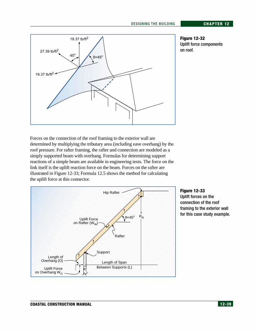
For the MWFRS, the roof pressure p = -27.39 lb/ft2 (taken from the WindLoad Example Problem in Chapter 11, page 11-46). The components of theforce are shown in Figure 12-32.
Figure 12-31Link #2 – connection of roofframing to exterior wall.
Link #2
Wall Studs
DoubleTop Plate
Metal HurricaneConnector
Roof Truss
Window Header
12-39COASTAL CONSTRUCTION MANUAL
CHAPTER 12DESIGNING THE BUILDING
Forces on the connection of the roof framing to the exterior wall aredetermined by multiplying the tributary area (including eave overhang) by theroof pressure. For rafter framing, the rafter and connection are modeled as asimply supported beam with overhang. Formulas for determining supportreactions of a simple beam are available in engineering texts. The force on thelink itself is the uplift reaction force on the beam. Forces on the rafter areillustrated in Figure 12-33; Formula 12.5 shows the method for calculatingthe uplift force at this connector.
Figure 12-32Uplift force componentson roof.
Figure 12-33Uplift forces on theconnection of the roofframing to the exterior wallfor this case study example.
19.37 lb/ft2
27.39 lb/ft2
19.37 lb/ft2
0=45o45o
Length of SpanBetween Supports (L)
Rafter
Uplift Forceon Rafter (WW)
0=45o
Support
Uplift Forceon Overhang WO
RL
RR
Length ofOverhang (O)
Hip Rafter

12-40 FEDERAL EMERGENCY MANAGEMENT AGENCY
CHAPTER 12 DESIGNING THE BUILDING
The uplift forces at each connection along one half of the hip roof are listed inTable 12.7 and are illustrated in Figure 12-34.
The forces do not vary significantly along the hip under the conditions of thecase study, i.e., 2-foot overhang, hip roof, and short spans. In this case, oneuplift connector could be selected and used at each connection point.
In-plane and normal horizontal forces to this connection must also bedetermined. The normal horizontal roof (perpendicular to the wall) forces atLink #2 can be determined by:
(6-ft rafter span)(2-ft rafter spacing)(19.37 lb/ft2) = 232 lb
Table 12.7Uplift Forces at EachConnection in Hip Roof forthe Case Study Example
NOTEGuidance on design require-ments is available in Table 2.2Aand Table 3.3, “Uplift Connec-tion Loads from Wind,” Com-mentary, in the SBC High WindEdition of the Wood Frame Con-struction Manual for One andTwo Family Dwellings (AFPA1995). Care must be exercisedin using prescriptive tables be-cause often many parametersmust be accounted for.
[12.9]
Determining UpliftForces at EachConnection inHip Roof
[12.9]
Formula 12.5Uplift Forces at Each Connection in Hip Roof
ΣF = 0 = RL + RR – [(ww)(L+O) + (wo)(O)](cos θ)
ΣMR = 0 = (RL)(L) – [(ww)(L+O)(L+O)/2 – (wo)(O)(L+O/2)](cos θ)
Solve for RL to determine uplift force at the roof-to-wall connection.
Uplift force = RL = [(27.39lb /ft2)(L+O)(L+O)/2 + 27.39lb/ft2 (O)(L+O/2)] cos θ (2ft rafter spacing)
Lwhere:
RL = reaction left in lb
RR = reaction right in lb
Ww = uplift force on rafter in lb/ft2
L = length of span between supports in ft
O = length of overhang in ft
W0 = uplift force on overhang in lb/ft2
θ= angle of roof, as measured from horizontal plane
Connection Point Uplift Force (lb)
1
2
3
4
5
6 (point at Link #2 –load path)
7
8
401
335
332
343
361
383
405
430

12-41COASTAL CONSTRUCTION MANUAL
CHAPTER 12DESIGNING THE BUILDING
There is also a normal force from suction pressure on the side wall below thisconnection. This force is 225 lb at the rafter:
So the total normal force = 232 lb + 225 lb = 457 lb
The in-plane lateral force at this individual Link is(the in-plane lateral force determined by Calculation12.12 and shown in Figure 12-45) (2-ft rafterspacing)/(wall length) = (4,000)(2)/(28) = 286 lb
It is assumed the designer is familiar with bending and shear analyses ofbeams. Rafters respond identically in both negative (gravity) and positive(uplift) bending and shear. Therefore, rafters are generally adequate to resistuplift unless the uplift pressures are greater than the minimum live loadrequirements. Trusses, however, can respond differently under uplift thanunder gravity loading. Designers should consult truss manufacturers to ensureadequate resistance to uplift exists.
Figure 12-34Uplift connections on hiproof.
Link #2ExteriorWall
WindowOpening
1 2 3 4 5 6 7 8
Hip RoofConnection Points
Hip Rafter

12-42 FEDERAL EMERGENCY MANAGEMENT AGENCY
CHAPTER 12 DESIGNING THE BUILDING
Three other important parameters must also be checked with the loads atLink # 2:
• roof framing size under upward bending, both midspan and at therafter notch for the top plate for cantilever bending of the overhang
• roof framing size under shear force
• stability of the unbraced bottom of the rafter under compression fromupward bending
Figures 12-35 and 12-36 show typical truss-to-wood-wall connections madewith metal connectors. Figure 12-37 shows a typical rafter-to-masonry-wallconnector that is embedded into the concrete-filled or grouted masonry cell.
Figure 12-35Typical connection of truss towood wall.
Figure 12-36Typical connection of truss towood wall.

12-43COASTAL CONSTRUCTION MANUAL
CHAPTER 12DESIGNING THE BUILDING
Link #3 – Top Wall Plate to Wall StudsLink #3 connects the top wall plates and the vertical wall stud over thewindow header. Figure 12-38 shows Link #3 for a wood wall. The forces atthis link are the same as those at Link #2. There is an additional dead loadfrom the weight of the top wall plates, but this downward load is insignificantand is ignored for purposes of this illustration.
Instead of calculating forces at each of the links, designers can consultreferences such as Table 3.3B of the High Wind Edition of the Wood FrameConstruction Manual for One and Two Family Dwellings (AFPA 1995),which provides prescriptive nailing requirements for uplift straps for roof-to-wall and wall-to-wall connections. This link is frequently made with wallsheathing acting as the connector, particularly when each roof framingmember is not supported over a stud (as in the case study example). The in-plane lateral force at Link #2 must be transferred to Link #3 through theconnector at Link #2.
The shear capacity of 8d box nails (used commonly to install sheathing) is78.4 lb each.
Figure 12-37Hurricane Andrew (1992), Dade County, Florida. Theseproperly placed hurricane straps were cast into theconcrete bond-beams atop a reinforced masonry walland wrapped over roof trusses.
NOTEAs in other examples, the shearcapacity from the 1997 NDS ismultiplied by a 1.6 load dura-tion factor. The wood is as-sumed to be hem-fir. Thesheathing is 1/2 inch thick.

12-44 FEDERAL EMERGENCY MANAGEMENT AGENCY
CHAPTER 12 DESIGNING THE BUILDING
The uplift load at this link is 383 lb, which requires383/78.4 = 4.9 or 5 nails over a 24-inch trussspacing.
For masonry or concrete walls, if a top wood sill plate is installed (so wood roofframing can be installed), the plate must be connected to the masonry withanchor bolts or cast-in straps. Uplift forces along the wall must be resisted bythe anchor bolts so the bolts must be spaced to resist pullout and the plate mustresist bending and splitting at the bolts. The important part about this connectionis that the wall plate must resist bending in the weak axis; placing anchor boltsclose together will assist in reducing the bending stress, but placing the bolts tooclose together can promote splitting along the grain. There are designrequirements in SSTD 10-97 (SBCCI 1997a) for the installation of anchor boltsin masonry.
Link #4 – Wall Sheathing to Window HeaderLink #4 connects the wall sheathing and the window header. The link isillustrated in Figure 12-39 for a wood wall. A failure at this link will normallyoccur from uplift or shear in the plane of the wall (racking). The uplift force isthe same as that at Link #2 minus some additional dead load, which, forpurposes of this illustration, is ignored. This approach again produces aconservative design. The uplift forces can be resisted by wall sheathing nailedto the header as described for Link #3. In-plane forces go to the full-heightwall segment through the double top plate as shown in Figure 12-45.
The window header must be checked for resistance to bending from gravity
Figure 12-38Link #3 – connection of topwall plate to wall stud.
[12.10]
Link #3
Wall Studs
DoubleTop Plate
Metal HurricaneConnector
Wall Sheathing
Roof Truss
Window Header

12-45COASTAL CONSTRUCTION MANUAL
CHAPTER 12DESIGNING THE BUILDING
loads and uplift and for wall-out-of-plane bending. These can be analyzedwith statics and beam theory. A header consisting of two 2x12’s is required inthe case study example.
In masonry construction, a masonry or concrete bond beam is required overthe window opening. This beam must also be able to resist bending in boththe plane of the wall and normal to the wall. SSTD 10-97 (SBCCI 1997a)includes prescriptive designs for masonry headers. Concrete and masonry areinherently weak in tension (bending). Reinforcing steel must be placed in thebond beam in order for the beam to adequately resist the bending stresses.The design of these members is beyond the scope of this manual; theprescriptive methods used in SSTD 10-97 or other concrete and masonryreferences should be used.
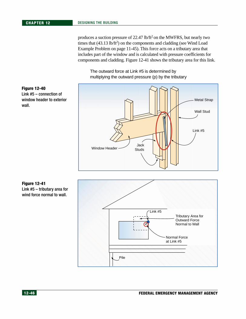
Link #5 – Window Header to E xterior WallLink #5, illustrated in Figure 12-40, connects the window header to theadjacent wall framing. The link must be checked in uplift and shear out of theplane of the wall.
Uplift forces at this link are the same as the resultant force at the end of thewindow header, which is 731 lb (determined by summing all of the upliftloads on the header and finding the resultant force on this end of the header).This uplift force can be transferred by a strap (shown in Figure 12-40) or byend-nailing, as described on page 12-47.
The outward force at this connection results from the negative (outward)pressure of wind as it travels around the south side of the building. The wind
Figure 12-39Link #4 – connection of wallsheathing to window header.
Wall Stud
Wall Stud
Wall Sheathing
WindowHeader
Jack Studs
Link #4
12-46 FEDERAL EMERGENCY MANAGEMENT AGENCY
CHAPTER 12 DESIGNING THE BUILDING
produces a suction pressure of 22.47 lb/ft2 on the MWFRS, but nearly twotimes that (43.13 lb/ft2) on the components and cladding (see Wind LoadExample Problem on page 11-45). This force acts on a tributary area thatincludes part of the window and is calculated with pressure coefficients forcomponents and cladding. Figure 12-41 shows the tributary area for this link.
The outward force at Link #5 is determined bymultiplying the outward pressure (p) by the tributary
Figure 12-40Link #5 – connection ofwindow header to exteriorwall.
Figure 12-41Link #5 – tributary area forwind force normal to wall.
Wall Stud
Metal Strap
Window Header
Link #5
JackStuds
Normal Forceat Link #5
Link #5Tributary Area forOutward ForceNormal to Wall
Pile

12-47COASTAL CONSTRUCTION MANUAL
CHAPTER 12DESIGNING THE BUILDING
area (A). This force is: (22.47 lb/ft2)(20.0 ft2) =449.4 lb on the MWFRS. The total outward force onthe 7-ft by 5-ft window is (43.13 lb/ft2)(35 ft2) =1,510 lb.
This is somewhat conservative in that the effectivewind area used for the pressure calculation inChapter 11 was 20 ft2, so the actual pressurecoefficient GCp is -1.2, not -1.3.
For the MWFRS, four 16d nails can be used in shear (142-lb shear capacityper 16d nail—see Table 12.8) if the header is end-nailed through theadjacent stud to resist the outward pressure, as shown in Figure 12-39.Figure 12-42 shows a metal connector used to resist uplift at a connectionsimilar to Link #5.
Fasteners for the cladding (window) also need to be determined in withdrawaland can be calculated by dividing the total outward force on the window bythe linear dimension of the window attachment device (e.g., nailing flange,window trim). The designer should verify that the window unit selected forthe project has been tested to the calculated wind suction pressures with thesame attachment method as that used in the field.
[12.11]
Table 12.8Shear Resistance Providedby 16d Box Nails
NOTEIt is particularly important fordesigners to verify that windowunits have been tested in thesame way they are to be in-stalled (e.g., with nailingflanges attached) and for win-dows to be installed in accor-dance with the manufacturer’srecommendations.
Number of 16d Nails Shear (lb)
1
2
3
4
5
6
7
8
142
284
426
568
710
852
994
1,136
Notes:1.Hem-fir with Specific Gravity = 0.43 is assumed.
2. 1/2" thick side member for withdrawal and 1-1/2" side member for shear is assumed.
3. Wind load factor = 1.6 is included.

12-48 FEDERAL EMERGENCY MANAGEMENT AGENCY
CHAPTER 12 DESIGNING THE BUILDING
Link #6 – Wall to Floor FramingLink #6 connects the wall and floor framing (see Figure 12-43). This link isvery important. Sufficient uplift resistance must be provided to keep theadjacent shear panel from overturning under horizontal wind (or seismic) loads.
The uplift forces and overturning moments are significant in this case; thelargest forces exist on the portion of the wall that functions as a shearwall.Link #6 is part of that shearwall.
Figure 12-42Metal connector at windowopening.
Figure 12-43Link #6 – connection of wallto floor framing.
Link #6
Wall Stud
Wall Stud
Band Joist
Bottom Plate
Pile
Two-MemberFloor Support
Beam
12-49COASTAL CONSTRUCTION MANUAL
CHAPTER 12DESIGNING THE BUILDING
Before loads at Link #6 are determined, the concept of a shearwall and itsassociated loads will be discussed.
ShearwallsShearwalls collect applied lateral forces and transfer those forces into thefoundation. In this case study, the shearwall that contains Link #6 collectsthe forces applied to the windward wall, the leeward wall, and the leewardroof areas.
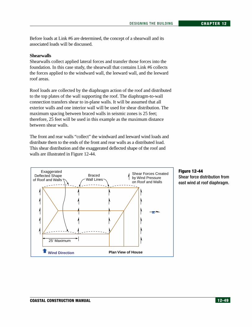
Roof loads are collected by the diaphragm action of the roof and distributedto the top plates of the wall supporting the roof. The diaphragm-to-wallconnection transfers shear to in-plane walls. It will be assumed that allexterior walls and one interior wall will be used for shear distribution. Themaximum spacing between braced walls in seismic zones is 25 feet;therefore, 25 feet will be used in this example as the maximum distancebetween shear walls.
The front and rear walls “collect” the windward and leeward wind loads anddistribute them to the ends of the front and rear walls as a distributed load.This shear distribution and the exaggerated deflected shape of the roof andwalls are illustrated in Figure 12-44.
Figure 12-44Shear force distribution fromeast wind at roof diaphragm.
Shear Forces Createdby Wind Pressureon Roof and Walls
Plan View of House
Exaggerated Deflected Shape
of Roof and WallsBraced
Wall Lines
Wind Direction
25' Maximum

12-50 FEDERAL EMERGENCY MANAGEMENT AGENCY
CHAPTER 12 DESIGNING THE BUILDING
Using the wind forces from Figure 12-10, the total applied force at the top ofthe shearwall is:
(p7)(10 ft)(25 ft)/4 + (p3)(8 ft)(25)/2 +(p
8)(10 ft)(25 ft)/4 = 4,000 lb
The lateral load (shear) at the bottom of the front and rear walls is taken intothe floor diaphragm.
The reaction at the top of the shearwall of 4,000 lb must be transmitted into theshearwall; this is done by means of a strut. The strut will transmit forces acrossthe top of openings; the strut in this case is the double top plate of the shearwall.The reaction at the strut will be in compression, and the design of this strut forlateral forces is not a consideration. However, the design of the top plate is animportant consideration in the distribution of the horizontal forces from the roofdiaphragms. See Design of Wood Structures (Breyer 1993) for explanations ofhow to handle this design. In shearwall design, it is commonly assumed thatareas over and under the openings do not help resist shear.
Figure 12-45 shows the south wall elevation and the loads that must becollected by this 28-foot-long wall. This figure also shows where resistance tothe overturning forces must be located. Loads are much more difficult tohandle properly when large openings exist in the wall. See references such asDiaphragms and Shearwalls (Diekmann, undated ) for additional informationon perforated shearwalls.
Figure 12-45Loads on south shearwall.
[12.12]
Link #6(See Figure 12-48)
Shear Panel
C
T
T = TensionC = Compression
C
T
C
T
6' 3'3'
4,000 lb
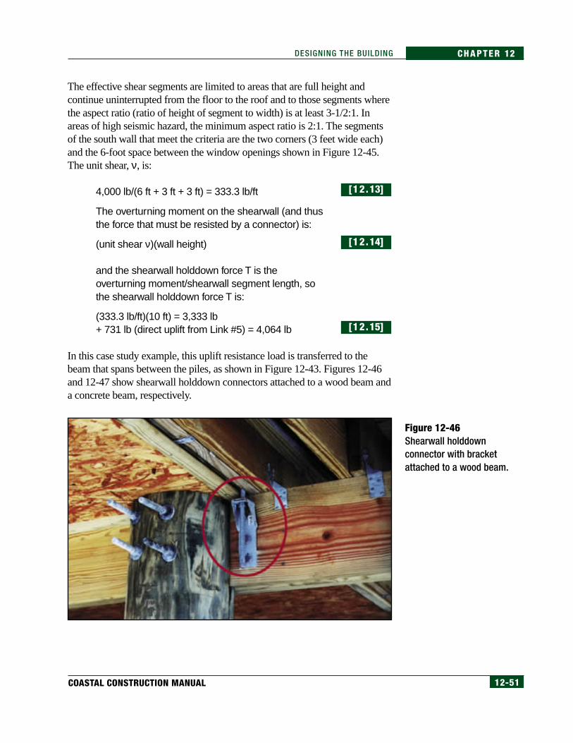
12-51COASTAL CONSTRUCTION MANUAL
CHAPTER 12DESIGNING THE BUILDING
The effective shear segments are limited to areas that are full height andcontinue uninterrupted from the floor to the roof and to those segments wherethe aspect ratio (ratio of height of segment to width) is at least 3-1/2:1. Inareas of high seismic hazard, the minimum aspect ratio is 2:1. The segmentsof the south wall that meet the criteria are the two corners (3 feet wide each)and the 6-foot space between the window openings shown in Figure 12-45.The unit shear, ν, is:
4,000 lb/(6 ft + 3 ft + 3 ft) = 333.3 lb/ft
The overturning moment on the shearwall (and thusthe force that must be resisted by a connector) is:
(unit shear ν)(wall height)
and the shearwall holddown force T is theoverturning moment/shearwall segment length, sothe shearwall holddown force T is:
(333.3 lb/ft)(10 ft) = 3,333 lb+ 731 lb (direct uplift from Link #5) = 4,064 lb
In this case study example, this uplift resistance load is transferred to thebeam that spans between the piles, as shown in Figure 12-43. Figures 12-46and 12-47 show shearwall holddown connectors attached to a wood beam anda concrete beam, respectively.
[12.13]
[12.14]
[12.15]
Figure 12-46Shearwall holddownconnector with bracketattached to a wood beam.

12-52 FEDERAL EMERGENCY MANAGEMENT AGENCY
CHAPTER 12 DESIGNING THE BUILDING
Shearwall deflection and aspect ratio must be checked against the criteriaestablished in the International Building Code (IBC) 2000 (ICC 2000a) andthe International Residential Code for One- and Two-Family Dwellings(IRC) 2000 (ICC 2000b). Chapter 23 of the IBC 2000 includes maximumaspect ratios for shearwalls. On the case study shearwalls, the aspect ratio is1.67 (10/6) and 3.33 (10/3). If the aspect ratio is less than 3-1/2:1, the IBCcriterion is met.
Horizontal deflection of the panel must be checked (see the equation given inChapter 23 of the IBC 2000). The predicted deflection in the braced framemay be greater as a result of factors such as crushing of the wood fibers at theholddown support members and movement of the holddown brackets. Thecalculated deflection from the IBC formula is 0.946 inch.
The wall has two large windows, so nearly a 1-inch deflection is likely to beexcessive. Glass breakage and water entry would probably result. To preventthis, a larger effective shear area or additional shear walls should be provided;however, these changes may radically affect the building layout.
Figure 12-47Shearwall holddown connector (without bracket topost) attached to a concrete beam.

12-53COASTAL CONSTRUCTION MANUAL
CHAPTER 12DESIGNING THE BUILDING
From the prescriptive shearwall design in Chapter 23 of the IBC 2000, onelayer of 3/8-inch Structural 1 Grade sheathing secured with 8d common nails,4 inches o.c., has a shear capacity of 360 lb/ft when 2x_ wall framing lumberis used and 400 lb/ft when 3x_ wall framing lumber is used.
To prevent glass breakage (which can contribute to failure of the entirebuilding through internal pressurization), a steel moment frame would need tobe installed around openings. The moment frame does not rely on the shearcapacity of the framed walls to resist horizontal forces and is more effective atpreventing excessive deflection. Moment frame design is discussed below.
Alternative methods of increasing shear capacity include the following:
• Installing additional interior shearwalls to further reduce lateral loadson the shearwall being designed.
• Decreasing the size of window openings to increase the effective width ofthe shearwall. In this case study, for every 1-foot increase in the effectiveshearwall length, the shear force per foot is reduced about 40 lb.
• Widening the building to increase the shearwall length while leavingthe windows the same size. Again, for every 1-foot increase in theeffective shearwall length, the shear force per foot is reduced by about40 lb.
The forces at Link #6 are as follows:
• normal force = 168 lb, which is resisted by sill plate nailing into theband joist
• horizontal force = unit shear of 333 lb x 1.33 = 443 lb, which also isresisted by sill plate nailing
• uplift force = 731 lb, except that at this exact location, the shearwallconnector will be installed with a capacity of 4,064 lb; therefore, anadditional uplift connector is not required
These forces and directions are illustrated in Figure 12-48.
Moment Frames
More moment-resistant frames are being built and installed in coastal homes(Hamilton 1997). The need for this special design results from morebuildings in coastal high hazard areas being constructed with large glazedareas on exterior walls, with large open interior areas, and with heights of twoto three stories. Figure 12-49 shows a typical steel moment frame.

12-54 FEDERAL EMERGENCY MANAGEMENT AGENCY
CHAPTER 12 DESIGNING THE BUILDING
Large glazed areas pose challenges to the designer because they create:
• large openings in shearwalls,
• large deflection in shearwalls, and
• difficulties in distributing the shear to the foundation.
Figure 12-48Load summary at Link #6.
Figure 12-49Steel moment frameat large opening.
Link #6
443 lb
168 lb
Tributary Area
Stud Spacing4,064 lb

12-55COASTAL CONSTRUCTION MANUAL
CHAPTER 12DESIGNING THE BUILDING
In residential construction, moment frames are frequently tubular steel.Tubular steel shapes can be selected that are close to the size of nominalframing lumber. This approach alleviates the need for special, time-consuming methods required to make the steel frame compatible with wood;however, frames made with tubular steel are more difficult to build thanframes made with “H” or “WF” flange shapes.
The advantages of the moment frames at window and door openings includethe following:
• The shear force/foot of wall is reduced or eliminated because the shearis transferred into the steel frame.
• The deflection is reduced because the load is transferred into the stiffersteel frame.
Link #7 – Floor Framing to Support BeamThe connection between the floor framing and the floor support beam isLink #7 (see Figure 12-50). The forces on this link include uplift and lateralforces transferred from the roof and walls.
The uplift (731 lb) and horizontal (443 lb) loads have been determinedpreviously except to account for the dead load from exterior walls and floorsand any shearwall uplift taken directly to the beam.
The connection at Link #7 is normally made with metal connectors (seeFigure 12-51); however, most metal connectors cannot be used for both upliftand lateral load transfer. When the connectors shown in Figure 12-50 are usedfor uplift resistance, additional clips must be used for lateral force transfer.This connection can also be made with a wood block nailed to the beam and
Figure 12-50Link #7 – connection of floorframing to support beam.
CROSS-REFERENCESee Figure 12-52 for an exampleof the use of wood blocking asan alternative to metal straps.
Link #7
Pile
Floor JoistBand Joist
Floor Framing
Two-MemberFloor Support Beam

12-56 FEDERAL EMERGENCY MANAGEMENT AGENCY
CHAPTER 12 DESIGNING THE BUILDING
floor joists (see Figure 12-52). Advantages of a wood connection, provided itis sufficient to transfer the uplift forces, are that it eliminates the need for ametal connector, which is easily corroded, and can be used for both uplift andlateral load transfer.
Figure 12-51Metal joist/beam connector.
Figure 12-52Wood joist/beamconnector.

12-57COASTAL CONSTRUCTION MANUAL
CHAPTER 12DESIGNING THE BUILDING
Table 12.8 (on page 12-47) lists the uplift resistance provided by 16d nailsacting in single shear. It is common practice to frame wood buildings with16d nails, so they have been used in this table of values. The wood floormembers will normally be 2x10s so there is sufficient width of the floor joistto install four nails on each side of the beam-to-wood uplift connector, for atotal of eight. This connection can then be used for a maximum uplift of 1,136lb shown for eight nails in Table 12.8 (page 12-47).
Link #8 – Floor Support Beam to Foundation (Pile)Link #8 connects the floor support beam to the top of the pile. This link,illustrated in Figure 12-53, must resist uplift and lateral loads placed on thebuilding by wind forces (and, when necessary, seismic forces). The pile atLink #8 must resist 1/31 of the total lateral load because there are 31 piles inthe foundation system. The total lateral force per pile was determined inCalculation 12.6. The wind load per pile is 989 lb.
The connection between the beam and the top of the pile is critical. Bolts,strong enough to resist shear forces at this link, are typically used. For thiscalculation, it is assumed the pile is sufficiently stiff and embedded to resisttwisting so the connection does not have to resist rotation. However, we knowthat, in practice, this is not true and that wind and flood forces can come froma direction such that the entire building can rotate about the tops of the piles.The rotation could be reduced by the installation of braces at each corner pilebetween the floor support beam in the plane of the floor (see Figure 12-54).An alternative method is sheathing the underside of the floor framing.
Figure 12-53Link #8 – connection of floorsupport beam to foundation.
Link #8
Wall Stud
Wall Stud
Band Joist
Bottom Plate
Pile
Two-MemberFloor Support
Beam
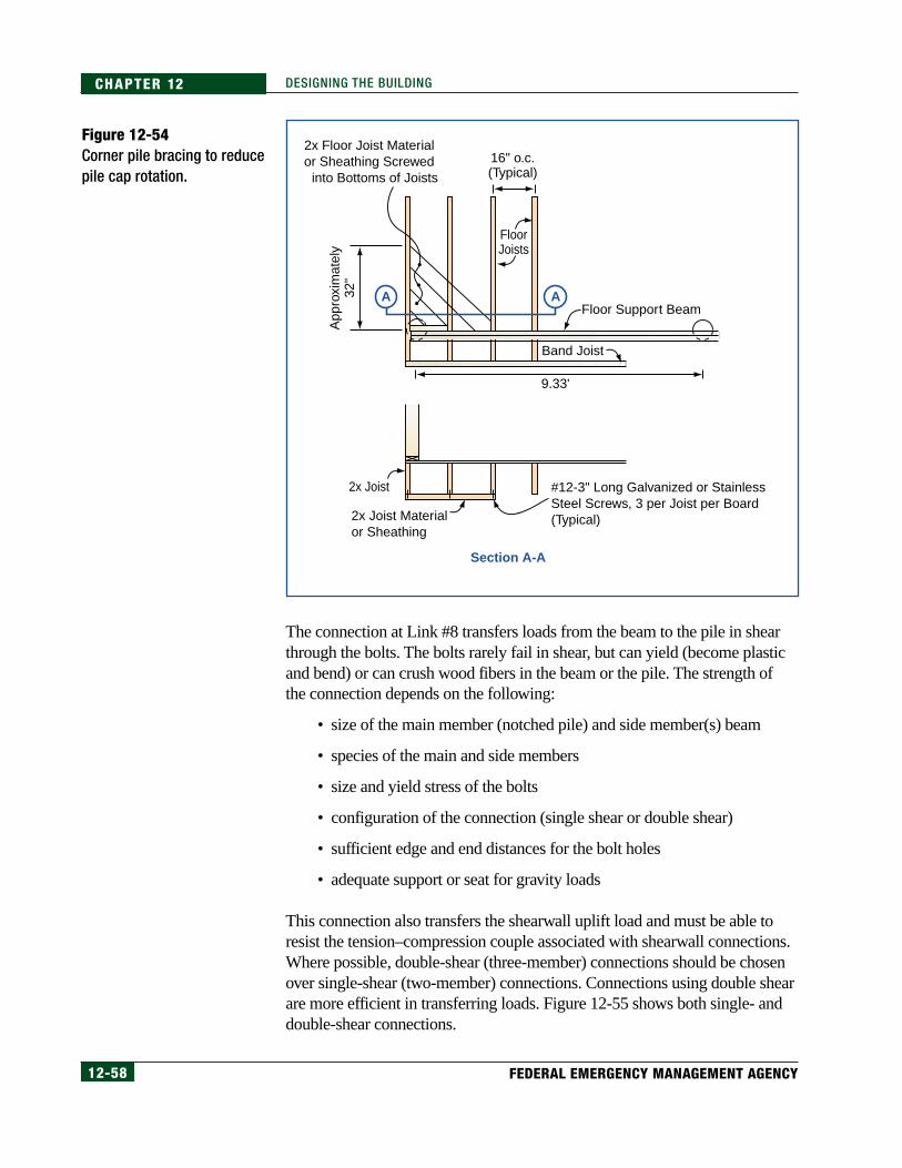
12-58 FEDERAL EMERGENCY MANAGEMENT AGENCY
CHAPTER 12 DESIGNING THE BUILDING
The connection at Link #8 transfers loads from the beam to the pile in shearthrough the bolts. The bolts rarely fail in shear, but can yield (become plasticand bend) or can crush wood fibers in the beam or the pile. The strength ofthe connection depends on the following:
• size of the main member (notched pile) and side member(s) beam
• species of the main and side members
• size and yield stress of the bolts
• configuration of the connection (single shear or double shear)
• sufficient edge and end distances for the bolt holes
• adequate support or seat for gravity loads
This connection also transfers the shearwall uplift load and must be able toresist the tension–compression couple associated with shearwall connections.Where possible, double-shear (three-member) connections should be chosenover single-shear (two-member) connections. Connections using double shearare more efficient in transferring loads. Figure 12-55 shows both single- anddouble-shear connections.
Figure 12-54Corner pile bracing to reducepile cap rotation.
Floor Support Beam
Band Joist
2x Joist Materialor Sheathing
#12-3" Long Galvanized or StainlessSteel Screws, 3 per Joist per Board(Typical)
2x Floor Joist Material or Sheathing Screwed
into Bottoms of Joists
16" o.c.(Typical)
FloorJoists
2x Joist
9.33'
App
roxi
mat
ely
32"
Section A-A
AA

12-59COASTAL CONSTRUCTION MANUAL
CHAPTER 12DESIGNING THE BUILDING
Determining yield modes of bolted connections is outside the scope ofthis manual. Chapter 8 of the NDS lists allowable loads on a variety ofbolted connections.
The allowable shear for one 5/8-inch-diameter steel bolt installed as followsis 2,324 lb:
• in a 7-1/2-inch-thick notched section of a pile
• supporting two 1-1/2-inch-thick side members (3 inches total)
• both members are southern pine (Specific Gravity = 0.55)
• in double shear
Resisting the 4,064-lb load (from Calculation 12.15) would require two bolts.
12.4.3 Foundation Design
12.4.3.1 Pile Design To determine pile capacities and embedment depths of driven piles, soilproperties must be either known or assumed. In the case study building, thesoil is assumed to have the following characteristics:
• medium dense sand, graded SP
• γ = 65 lb/ft3 (unit weight of saturated sand)
• φ = 30° (angle of internal friction)
The pile design now must be completed for the following load cases:
• gravity (compressive) loads
• uplift (tension) loads
• horizontal loads and the moments developed by horizontal loads
Pile capacity formulas used in this example are obtained from the U.S.Navy’s Design Manual 7.2, Foundation and Earth Structures (U.S.Department of the Navy 1982).
Figure 12-55Single and double shearconnections.
Connector
Single Shear
FramingMembers
Shear Plane Shear Planes
Double Shear
Connector
NOTESee Table 12.13, on page12-69, for a discussion of pileinstallation methods.
NOTEThe minimum recommendedpile spacing is 8 feet. Thisspacing will allow debris toflow between piles.
NOTEPile design involves complexsoils mechanics theory; pursu-ing soil mechanics beyond whatis included in the formulas forcompression and tension pilecapacity is beyond the scope ofthis manual. This manual doesnot provide a single pile embed-ment depth recommendation forall coastal areas.

12-60 FEDERAL EMERGENCY MANAGEMENT AGENCY
CHAPTER 12 DESIGNING THE BUILDING
Gravity Loads
For gravity loads, a 15-foot embedment depth will be assumed. With the pileextending approximately 9 feet above grade, the total pile length will beapproximately 24 feet. Formula 12.6 determines the allowable compressionload on the pile. The resistance of the pile results from end bearing and friction.
When the variables associated with the soil type given in this case study areused in the formula, Qult = 34,015 lb. The foundation guide recommends anFS of 3.0; thus, Qallow = 34,015/3 = 11,338 lb is the allowable capacity incompression for this pile with an embedment depth of 15 feet.
From the determination of dead load (Calculation 12.1), plus a live load of 20lb/ft2 on the roof and 40 lb/ft2 on the floor of the tributary area, the total deadand live load on the case study pile is 5,974 lb. The compression load fromoverturning adds another 4,736 lb, so the total compression load is10,710 lb. The allowable compression load is greater than the required load,so the pile is adequate for dead load, live load, and compression andoverturning loading.
Recalculating the allowable compression load to account for 1.8 feet of scour(see Section 11.6.11 in Chapter 11 of this manual) reduces the allowablecompression load to 10,594 lb, which is still adequate to support the requireddead and live loads. If this pile were augered into place instead of driven, theallowable compression load would be reduced to 4,466 lb, or less than 40percent of the allowable load for a driven pile. For comparison purposes, seeTable 12.9, on page 12-62, for allowable loads on driven, augered, and jettedwood piles for this case study.
UltimateCompressionCapacity of a SinglePile (Developed byEnd Bearing andFrictionalResistance)
Formula 12.6 Ultimate Compression Capacity of a Single Pile
where:Qult = ultimate load capacity in compression (lb)
PT =effective vertical stress at pile tip (lb/ft2)
Nq = bearing capacity factor
AT = area of pile tip (ft2)
kHC = earth pressure coefficient in compression
P0 = effective vertical stress over depth of embedment, D (lb/ft2)
δ = friction angle between pile and soil
s = surface area of pile per unit length (ft)
D = depth of embedment (ft)
Qult = PTNqAT + Σ(kHC)(P0)D(tan δ)(s)

12-61COASTAL CONSTRUCTION MANUAL
CHAPTER 12DESIGNING THE BUILDING
Ultimate TensionCapacity of a SinglePile (Developed byFrictional Resistance)
Uplift Loads
Pile capacity in tension loads is given in Navy Design Manual 7.2 (USDN 1982).Tension capacity is required to resist uplift and overturning loads. Formula 12.7determines the tension capacity in a single pile.
The formula predicts a tension capacity (Tult) (with 1.8 feet of scour) of14,965 lb. With the recommended FS of 3.0, the allowable tension capacity ofthe 15-foot pile is Tallow = 14,965/3 = 4,988 lb.
The frictional resistance required of the row of piles under the front porch ifonly those piles resisted the net overturning moment shown in Calculation12.5 is 1,259,704 ft-lb/38 feet/7 piles or 4,736 lb/pile. Therefore, a 15-footembedment satisfies overturning tension as well as compression.
Direct tension must also be checked. Figure 12-56 shows the tributary areathat creates this tension. Depending on shearwall connection location, it isalso possible that the tension or compression load from the shearwallconnector will be concentrated on one pile (as it is in this case study).
The total tension load on the pile highlighted in Figure 12-56 is 8,586 lb,which exceeds the allowable tension load for the 15-foot embedment. Thispile needs to be embedded 25 feet to resist the total tension load in thiscase study.
Table 12.9 summarizes the allowable compression and tension (uplift)capacities of wood piles placed 15 feet below the ground surface.
Formula 12.7 Ultimate Tension Capacity of a Single Pile
where:Tult = ultimate load capacity in tension (lb)
kHT = earth pressure coefficient in tension
P0 = effective vertical stress over depth of embedment, D (lb/ft2)
δ = friction angle between pile and soil
s = surface area of pile per unit length (ft)
D = depth of embedment (ft)
Tult = Σ(kHT)(P0)(tan δ)(s)(D)
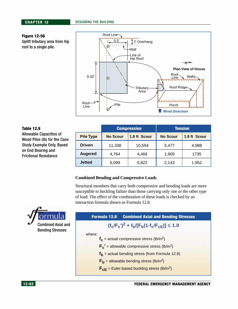
12-62 FEDERAL EMERGENCY MANAGEMENT AGENCY
CHAPTER 12 DESIGNING THE BUILDING
Combined Bending and Compressive Loads
Structural members that carry both compressive and bending loads are moresusceptible to buckling failure than those carrying only one or the other typeof load. The effect of the combination of these loads is checked by aninteraction formula shown as Formula 12.8.
N
Plan View of House
RoofLine
Roof Ridge
Porch
Walls
Roof Line
Roof Line
Line ofHip Roof
Pile
TributaryArea
2' Overhang5.5'
9.33'
Wall
Wind Direction
Figure 12-56Uplift tributary area from hiproof to a single pile.
Table 12.9Allowable Capacities ofWood Piles (lb) for the CaseStudy Example Only, Basedon End Bearing andFrictional Resistance
Combined Axial andBending Stresses
TensionCompression
Pile Type
Driven
Augered
Jetted
No Scour 1.8 ft Scour No Scour 1.8 ft Scour
11,338
4,764
6,099
10,594
4,466
5,822
5,477
1,905
2,143
4,988
1735
1,952
Formula 12.8 Combined Axial and Bending Stresses
where:fc = actual compressive stress (lb/in2)
Fc' = allowable compressive stress (lb/in2)
fb = actual bending stress (from Formula 12.9)
Fb = allowable bending stress (lb/in2)
FcE = Euler-based buckling stress (lb/in2)
(fc/Fc')2 + fb/[Fb(1-fc/FcE)] ≤ 1.0

12-63COASTAL CONSTRUCTION MANUAL
CHAPTER 12DESIGNING THE BUILDING
Actual compressive stress fc is 10,710 lb (from page 12-60)/pile area of 63.62in2 = 168 lb/in2. The allowable compressive stress Fc' from the NTPC (1995) is:
Fc' = FcCdCldCtCptCspCpCcs
Fc' = (1,278)(1.0)(1.6)(1.0)(0.9)(0.8)(0.15)(1.054) =233 lb/in2
From the NTPC (1995), the allowable bending stress Fb' equals:
Fb' = FbCdCldCtCptCfCspCcs
Fb' = (2,612)(1.0)(1.6)(1.0)(0.9)(1.0)(0.77) (1.054) =3,052 lb/in2
The adjustment factors are listed in the NTPC. CdCtCpt are functions of thepile material and loading; CfCspCcs are functions of the pile dimensionsand length.
From Formula 12.9, fb = (989 lb)(13.5 ft) (12 in/ft)/71.57 in3 = 2,239 lb/in2
Horizontal Loads
The horizontal load on an unbraced pile causes the pile to deflect as illustratedin Figure 12-57. ASCE 24-98, Section C5.2.4.7 (ASCE 1998a), includes aformula (also included in this manual as Formula 12.10) for determining theallowable length of a pile above the point of fixity. The point of fixity is thepoint at which the pile is assumed to be fixed for translation and rotation, andit occurs at some distance (d) below the ground surface.
In Figure 12-57, the distance H includes the height above original ground plusthe additional height resulting from any expected erosion and scour. In thiscase study, H = 9.5 feet + 1.8 feet = 11.3 feet. The total effective length L isdetermined by Formula 12.10.
[12.16]
[12.17]
Determination ofActual BendingStress
NOTECp in Calculation 12.16 is a col-umn stability factor. The valueof this factor depends on the ef-fective column length from For-mula 12.10. Section 3.7 of theNDS provides a formula for Cp.
The adjustment factors used inCalculations 12.16 and 12.17 aredescribed in detail in the Tech-nical Guidelines for ConstructionWith Treated Round Timber Pil-ings, by the National Timber Pil-ing Council (NTPC 1995).
Formula 12.9Determination of Actual Bending Stress
where:fb = actual bending stress (lb/in2)
P = applied lateral load (lb)
L = allowable unbraced pile length (feet) (from Formula 12.10)
S = section modulus (in3)
fb = (PxL)(12 in/ft)/S

12-64 FEDERAL EMERGENCY MANAGEMENT AGENCY
CHAPTER 12 DESIGNING THE BUILDING
Table 12.10 lists recommended values for nh, the modulus of subgradereaction, for a variety of soils (Bowles 1996), which is used in Formula 12.10.
Figure 12-57Deflected pile shape for anunbraced pile. The effectivelength of this pile is equal toL x (K=2.1).
Horizontal Load
Centerline ofDeflected Pile AfterHorizontal Load
Centerline ofPile Before Horizontal Load
Point of Fixity
Eroded GroundSurface
Localized Scour
H
d
L
L = Unbraced Length
H = Height of Pile Above Eroded Ground Surface (Including Localized Scour)
d = Depth of Embedment From Level of Localized Scour to Point of Fixity
Effective Length ofUnbraced Pile
Table 12.10Values of nh, Modulus ofSubgrade Reaction
Formula 12.10 Effective Length of Unbraced Pile
where:L = length of pile (feet)
d = depth of embedment from level of localized scour to point of fixity = (1.8)(EI/nh)1/5 (inches)
E = Modulus of Elasticity of pile material (lb/in2)
I = moment of inertia of pile material (in4)
nh = modulus of subgrade reaction (lb/in2)
K = effective length factor based on end conditions
H = length of pile between horizontal load and eroded ground surface (see Figure 12-57) (feet)
L = K(H + d/12)
Soilnh Modulus of Subgrade
Reaction (lb/In3)
Dense sandy gravel
Medium dense coarse sand
Medium sand
Fine or silty fine sand
Medium clay (wet)
Soft clay
800-1,400
600-1,200
400-1,000
290-700
150-500
6-150

12-65COASTAL CONSTRUCTION MANUAL
CHAPTER 12DESIGNING THE BUILDING
The pile is assumed to have the following characteristics:
• material: southern pine with a modulus of elasticity (E) of 1,500,000lb/in2
• tabulated fiber bending stress: Fb = 2,612 lb/in2 1995 National TimberPiling Council (NTPC)
• section: round timber with a nominal 9-inch diameter (8 inches at base;10 inches at top); moment of inertia (I) = 322 in4; section modulus (S)= 71.57 in3 (at 9-inch section)
• end restraints: free at the top and fixed at the base; the fixed/free endconditions of a cantilever pile produce an effective length factor (K) of2.1 (from Appendix G of the NDS).
Calculating the pile length L for a round timber pile using Formula 12.10,assuming nh= 700 lb/in3:
d = (1.8)[(1.5x10⁶)(322)/700]1/5 = 26.5 in
L = (11.3 ft + 26.5/12) = (11.3 + 2.2) =13.5 ft
This length represents the unbraced length of the pile to its point of fixity.This length is used to determine the actual bending stress fb (Formula 12.9)and the Cp factor used in Calculation 12.16
Now using Formula 12.8, the effect of combined bending and axial loads isdetermined. Using fb = 2,239 lb/in2, Fb = 3,052 lb/in2, fc = 168 lb/in2, andFc = 233 lb/in2, the interaction formula = 3.15, which is much greater than1.0. Therefore, this pile design does not work. The alternatives are as follows:
• larger piles
• reduced spacing
• shorter effective length
• piles with greater strength than wood
In order for a wood pile to be acceptable, the effective length shown in the lastcolumn of Table 12.11 must be greater than approximately13.5. This length isdetermined by working backwards through Formula 12.8 and the factor Cp todetermine what the maximum effective length could be when Formula 12.8yields a value of 1.0. As can be seen from Table 12.11, the pile must be atleast 12 inches in diameter for the load and height criteria to be met.
Another way to make this pile design acceptable is to shorten the effectivelength with bracing. This method is discussed in Section 12.4.5
[12.18]

12-66 FEDERAL EMERGENCY MANAGEMENT AGENCY
CHAPTER 12 DESIGNING THE BUILDING
Allowable Shear Stress
From the NTPC, the allowable shear stress Fv' equals:
Fv' = FvCldCtCpt
Fv' = (110)(1.6)(1.0)(0.9) = 158 lb/in2
The actual average shear stress is the horizontal load at the pile-groundintersection from Calculation 12.7 divided by the area of the pile, or 2,293 lb/63.62 in2 = 36 lb/in2. The maximum shear stress is 4/3 the average shearstress, or 48 lb/in2. Thus shear is not a failure mode for the pile under the casestudy conditions.
Deflection
From beam theory, the deflection at the top of the case study 13.5-foot-long(H+d only) cantilevered pile horizontally deflected by a 989-lb load is 2.9inches. This is an excessive amount of deflection that most buildingoccupants would find unacceptable. This deflection is being caused by veryhigh winds, however, in what is expected to be an unoccupied house. Thisdeflection can be reduced by bracing to reduce the unbraced length. SeeSection 12.4.5 for additional information.
Other Pile Types
Other types of piles and methods of installation are available, including thefollowing:
• precast concrete
• cast-in-place concrete
• steel H-sections
• concrete filled steel pipe piles
Table 12.11 Maximum Unbraced Lengths of Various Pile Materials for the Case Study Loadsa
Materialb E (lb/in2) S (in3)FB
(lb/in2)Length
(ft)I (in4)Pile
Wood – 9" diameter
Wood – 10" x 10" square
Wood – 12" diameter
P.T.S.Y.P.
P.T.S.Y.P.
P.T.S.Y.P.
1,500,000
1,500,000
1,500,000
322
678.8
1,018
3,052
3,052
3,052
7.1
12.8
15.1
71.57
142.9
169.65
a Buckling and the interaction formula not considered.b P.T. = Pressure Treated; S.Y.P. = Southern Yellow Pine.

12-67COASTAL CONSTRUCTION MANUAL
CHAPTER 12DESIGNING THE BUILDING
Some advantages of, and special considerations for, of each of these are listedin Table 12.12.
There are several methods for installing piles, including driving, augering,and jetting.
Driving a pile is hitting the top of the pile with a pile driver hammer untilthe pile reaches the desired depth. In some areas, piles are driven withvibratory hammers, which generate vertical oscillating movements thatreduce the soil stress against the pile and make the piles easier to drive.Ultimate load resistance is achieved by a combination of end bearing of thepile and frictional resistance between the pile and the soil. A record of the
Table 12.12Pile Material Selection
Pile Material Type Special ConsiderationsAdvantages
Wood (ASTM-D25)
Concrete (ACI 318 for concrete, ASTM-A15 for reinforcing steel)
Steel (ASTM-A36)
• Comparatively low initial cost
• Permanently submerged piles are resistant to decay
• Relatively easy to drive in soft soil
• Easy to connect to wood framing
• Suitable for friction and end bearing pile
• High compressive load capacity for precast/ prestressed piles
• Corrosion resistant• Can be driven through
some hard material• Suitable for friction and
end bearing pile• Reinforced piles have
high bending resistance
• High resistance to bending
• Easy to splice• Available in many
lengths and sizes• Able to drive through
hard subsurface material
• Suitable for end bearing• High compressive
capacity
• Difficult to splice• Subject to eventual
decay when in soil or intermittently submerged in water
• Vulnerable to damage from driving — easy to split
• Comparatively low compressive load
• Relatively low allowable bending stress
• High initial cost• Difficult to splice• Vulnerable to breakage• Must be reinforced, no
bending allowed in plain concrete
• More difficult to attach to wood framing
• Not usable in high seismic areas
• Vulnerable to corrosion• May be permanently
deformed if impacted by heavy object
• High initial cost• Some difficulty attaching
wood framing
12-68 FEDERAL EMERGENCY MANAGEMENT AGENCY
CHAPTER 12 DESIGNING THE BUILDING
blow counts from the pile driver can be used with a number of empiricalformulas to determine capacity.
Augering is drilling a full or partial pile-diameter hole in the soil to somepredetermined depth, installing the pile, and then driving the pile into the holeuntil it reaches refusal.
Jetting is removing soil with a jet of water (or air) as the pile is driven, andthen driving the pile down until it reaches refusal. Both augering and jettingremove natural, undisturbed soil along the side of the pile. Load resistance forboth of these methods is achieved by a combination of end bearing andfrictional resistance, although the frictional resistance is much less than thatprovided by driven piles.
Figure 12-58 illustrates the three pile installation methods. Table 12.13 listsadvantages and special considerations for each method.
It is important to note from Table 12.13 that the 40-percent reduction in the kfactors for compression and tension loads on augered and jetted piles reducesthe allowable loads by the same percentage. Therefore, for the case studybuilding, if the piles were augered or jetted into place, the allowable load incompression would be reduced to 2,710 lb, which is then less than therequired load of 10,710 lb. The allowable load in tension is reduced to1,220 lb, which is less than the net uplift load of 8,429 lb. Consequently, if thepiles were installed by augering or jetting, they would have to be embeddedfurther to resist both the compression and tension loads .
12.4.3.2 Masonry or Concrete ColumnsWhile local floodplain regulations require the use of open foundations inV zones, foundation materials are not restricted to wood as long as thefoundation is anchored to resist flotation, collapse, and lateral movement.Solid foundation walls may be constructed in A zones, but must comply withthe NFIP and have openings to equalize hydrostatic pressure. Columnsconstructed of concrete or reinforced masonry can be used, but must beconstructed on a solid foundation such as a spread footing or a pile cap todistribute loads onto undisturbed soils below the anticipated erosion and scourdepth. This type of foundation is normally assumed to be fixed at its base.

12-69COASTAL CONSTRUCTION MANUAL
CHAPTER 12DESIGNING THE BUILDING
Figure 12-58Pile installation methods.
Table 12.13 Selection of Pile Installation Method
Driven Augered
Hammer toSet in Place
Hammer toSet in Place
Water Injected toCreate Hole for Pile
Hammer(or vibratoryhammer)Drives Pile
AugeredHole
Jetted
Pile InstallationMethod Special ConsiderationsAdvantages
• Well suited for friction pile
• Common construction practice
• Pile capacity can be determined empirically
• Economical
• Minimal driving vibration to adjacent structures
• Well suited for end bearing
• Visual inspection of some soil stratum possible
• Convenient for low headroom situations
• Easier to maintain column lines
• Minimal driving vibration to adjacent structures
• Well suited for end bearing
• Easier to maintain column lines
• Difficult at times to reach terminating soil strata, which is not necessary for friction piles
• Difficult to maintain plumb during driving and thus maintain column lines
• Requires subsurface investigation
• Not suitable for highly compressible material
• Disturbs soil adjacent to pile, thus reducing earth pressure coefficients kHC and kHT to 40 percent of that for driven piles
• Capacity must be determined by engineering judgment or load test
• Requires subsurface investigation
• Disturbs soil adjacent to pile, thus reducing earth pressure coefficients kHC and kHT to 40 percent of that for driven piles
• Capacity must be determined by engineering judgment or load test
Driven
Augered
Jetted

12-70 FEDERAL EMERGENCY MANAGEMENT AGENCY
CHAPTER 12 DESIGNING THE BUILDING
Figure 12-59Design method for reducingeffective column length of acantilever pile.
CALCULATION OFUNBRACED PILE
LENGTH (L)Distance from top of pile to DFE= 2 feet
Distance from DFE to erodedground surface = 9.5 feet
Scour = 1.8 feet
L = 2 feet + 9.5 feet + 1.8 feet= 13.3 feet
A way to reduce this unbraced length is to “fix” the column in both translationand rotation at some point along its length. A timber pile can be fixed in onlytranslation by the addition of horizontal grade beams. These grade beams maybe constructed of concrete or wood; they must be installed so that they areself-supporting and the effects of scour have been considered. Theeffectiveness of grade beams in “fixing” the piles is subject to engineeringjudgment. See Figure 12-59 for an illustration of this design concept.
Guidance on the design of concrete or masonry piers on spread footingsfollows. It will be obvious why the use of these foundation methods in V zonesand coastal A zones is often not appropriate. It should be noted, however, thatfoundations of this type can be appropriate in V zones and coastal A zoneswhere bedrock, coral rock, or some other stratum that terminates erosion andscour is present.
First for V zones, the design example that follows will use the loads developedin previous sections. From previous examples and the Flood Load ExampleProblem presented on page 11-30 in Chapter 11, L = 13.3 feet (see calculationat left). It is assumed that the allowable soil bearing pressure is 2,000 lb/ft2.Figure 12-60 illustrates a column on a spread footing with the axial (Pa) andlateral (Pl) forces determined previously.
Horizontal Load
Centerline ofDeflected Pile AfterHorizontal Load
Centerline ofPile Before Horizontal Load
Top of Grade Beam FlushWith Surface of ErodedGround
HL
L = Unbraced LengthH = Height of Pile Above Eroded Ground Surface
(Including Localized Scour)

12-71COASTAL CONSTRUCTION MANUAL
CHAPTER 12DESIGNING THE BUILDING
The following foundation elements and design parameters must bedetermined:
• soil bearing pressure assuming a footing size or a footing size assuming2,000-lb/ft2 soil bearing pressure
• bending stresses in the column, to determine the amount of reinforcingsteel to place in the column
• compressive stresses in the column, to determine whether these stressesexceed the allowable for the material selected for the column
• bending stresses in the footing, to determine the amount of reinforcingsteel to place in the footing
This foundation type must be designed for the same conditions as the pile –gravity loads, uplift loads, horizontal loads, and the resulting bending thatoccurs in the column.
Gravity Loads
The footing must be large enough to carry the following loads:
• weight of the foundation
• axial load Pa
Figure 12-60Column/pier on a spreadfooting.
Elevation 1.7ftNGVD
13.3'
x
Elevation 15.0 ft NGVD
Pa = 10,710 lb
Pl = 989 lb
Column/Pier
1'Footing
L
Frost Depth After Scour
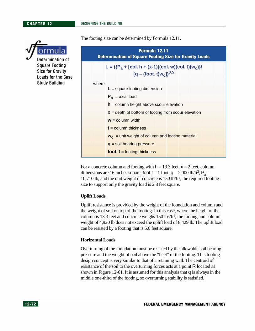
12-72 FEDERAL EMERGENCY MANAGEMENT AGENCY
CHAPTER 12 DESIGNING THE BUILDING
The footing size can be determined by Formula 12.11.
For a concrete column and footing with h = 13.3 feet, x = 2 feet, columndimensions are 16 inches square, foot.t = 1 foot, q = 2,000 lb/ft2, Pa =10,710 lb, and the unit weight of concrete is 150 lb/ft3, the required footingsize to support only the gravity load is 2.8 feet square.
Uplift Loads
Uplift resistance is provided by the weight of the foundation and column andthe weight of soil on top of the footing. In this case, where the height of thecolumn is 13.3 feet and concrete weighs 150 lbs/ft3, the footing and columnweight of 4,920 lb does not exceed the uplift load of 8,429 lb. The uplift loadcan be resisted by a footing that is 5.6 feet square.
Horizontal Loads
Overturning of the foundation must be resisted by the allowable soil bearingpressure and the weight of soil above the “heel” of the footing. This footingdesign concept is very similar to that of a retaining wall. The centroid ofresistance of the soil to the overturning forces acts at a point R located asshown in Figure 12-61. It is assumed for this analysis that q is always in themiddle one-third of the footing, so overturning stability is satisfied.
Determination ofSquare FootingSize for GravityLoads for the CaseStudy Building
Formula 12.11Determination of Square Footing Size for Gravity Loads
where:L = square footing dimension
Pa = axial load
h = column height above scour elevation
x = depth of bottom of footing from scour elevation
w = column width
t = column thickness
wc = unit weight of column and footing material
q = soil bearing pressure
foot. t = footing thickness
L = ({Pa + [col. h + (x-1)](col. w)(col. t)(wc)}/[q – (foot. t)wc])0.5
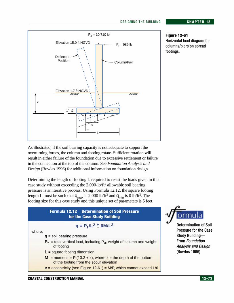
12-73COASTAL CONSTRUCTION MANUAL
CHAPTER 12DESIGNING THE BUILDING
As illustrated, if the soil bearing capacity is not adequate to support theoverturning forces, the column and footing rotate. Sufficient rotation willresult in either failure of the foundation due to excessive settlement or failurein the connection at the top of the column. See Foundation Analysis andDesign (Bowles 1996) for additional information on foundation design.
Determining the length of footing L required to resist the loads given in thiscase study without exceeding the 2,000-lb/ft2 allowable soil bearingpressure is an iterative process. Using Formula 12.12, the square footinglength L must be such that qmax is 2,000 lb/ft2 and qmin is 0 lb/ft2. Thefooting size for this case study and this unique set of parameters is 5 feet.
Figure 12-61Horizontal load diagram forcolumns/piers on spreadfootings.
Determination of SoilPressure for the CaseStudy Building—From FoundationAnalysis and Design(Bowles 1996)
Elevation 1.7 ft NGVD
Elevation 15.0 ft NGVD
Pa = 10,710 lb
Pl = 989 lb
R
e
L
Column/Pier
DeflectedPosition
1'
x
Formula 12.12 Determination of Soil Pressurefor the Case Study Building
q = Pt /L2 + 6M/L3
where:q = soil bearing pressure
Pt = total vertical load, including Pa, weight of column and weight of footing
L = square footing dimension
M = moment = Pl(13.3 + x), where x = the depth of the bottom of the footing from the scour elevation
e = eccentricity (see Figure 12-61) = M/P, which cannot exceed L/6

12-74 FEDERAL EMERGENCY MANAGEMENT AGENCY
CHAPTER 12 DESIGNING THE BUILDING
In order for the pier and footing to act as one unit, the connection between thefooting and the base of the pier must be fixed. This fixed condition can onlybe developed with sufficient steel reinforcement that is adequately anchoredinto both the footing and the pier.
When the uplift load of 8,429 lb is considered with the lateral loads (whichwould be the case for the windward- or seaward-most row of piles), andqmax is 2,000 lb/ft2 and qmin is 0 lb/ft2, the required footing size is 9.7 feetsquare. Thus the footing size is governed by the combination of uplift andlateral forces.
A 9.7-foot-square footing is not practical when the pile spacing is 9.33 feeto.c. in one direction and 11 feet o.c. in the other direction. In addition,excavation in sand for a 9.7-foot-square footing 4 feet below grade results in,for all practical purposes, a continuous 1-foot-thick concrete mat under thehouse, approximately 4 feet below grade. This type of foundation, known as a“mat” or “raft” foundation, is used in some locations along the coast of theUnited States.
Allowable Bending Stress and Moment
Design for bending in concrete or masonry involves designing steelreinforcement to resist tensile stresses (because neither concrete nor masonryhas much tensile strength) and designing the section to resist failure incompression or crushing. Design guidance can be found in many of thereferences listed at the end of this chapter. The determination of these stressesinvolves effort beyond the scope of this manual and is left to the designer.
If the case study building were placed in an A zone where the breaking waveheight is just less than 3 feet (see Chapter 6 for a description of A zones) andall other loads on the building were the same as the example above, thefollowing design parameters would apply:
• The lateral force is minimally reduced.
• The height of the building above the ground (after scour) is only 1 footlower than the V zone building (see Figure 11-13 for BFEs for the casestudy) so “moment arms” are practically the same as before.
• With the moments on the concrete or masonry piers practically thesame as before and forces only slightly reduced, the footing length ispractically the same as the footing length required in the V zone.
As a result, and for other reasons noted in previous chapters, this manualrecommends that the foundation standards applied in V zones also beused for coastal A zone construction.
12-75COASTAL CONSTRUCTION MANUAL
CHAPTER 12DESIGNING THE BUILDING
Prescriptive designs, including column sizes, reinforcing requirements, andallowable heights, are available for both masonry and concrete materials.Designers should refer to the Masonry Designers’ Guide (ACI 1993) andBuilding Code Requirements for Masonry Structures, ACI 530, (ACI 1999a)for information on how to design masonry columns, and to Building CodeRequirements for Structural Concrete and Commentary, ACI 318, (ACI1999b) for information on how to design concrete columns.
12.4.4 Other Important Load PathsSeveral additional design considerations must be investigated for the casestudy building in order for the design to be complete. The details of theseinvestigations are left to the designer, but they are mentioned here to morethoroughly cover the subject of continuous load paths and to point out thatmany possible paths require investigation.
From Figure 12-16, the following vertical load paths should also beinvestigated:
• uplift of the front porch roof
• uplift of the main roof section that spans the 28-foot width of thebuilding
The following lateral load paths also need to be investigated:
• lateral load on the front gable wall (see “Shearwalls” on page 12-49)
• interior shearwalls noted on Figure 12-44
• possible twisting of the L-shaped front during either a wind or seismicevent (see Section 12.4.4.2)
12.4.4.1 Gable Wall SupportThere are many cases of failures of gable-end walls during high-wind events.The primary failure modes in gable-end walls are as follows:
• A gable wall that is not braced into the structure collapses, and the roofframing falls over (see Figure 12-62).
• An unsupported gable-end eave ladder used for overhangs is lifted offby the wind and takes the roof sheathing with it.
• The bottom chord of the truss is pulled outward, twisting the truss andcausing an inward collapse.
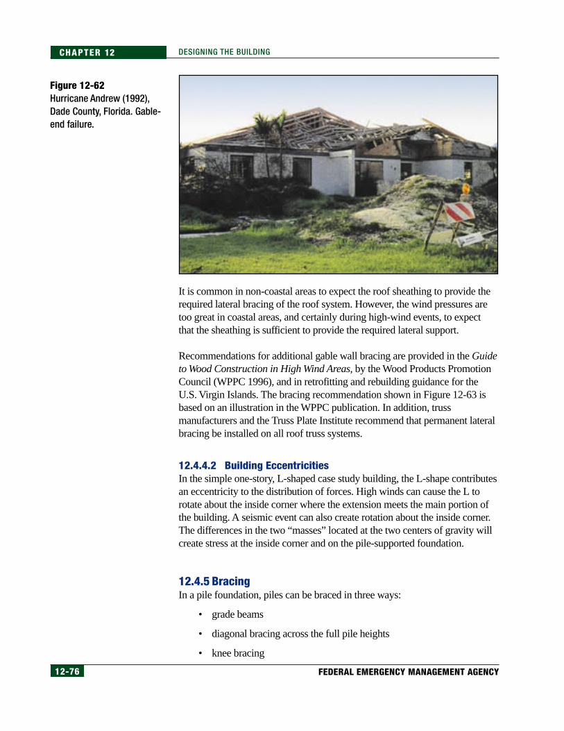
12-76 FEDERAL EMERGENCY MANAGEMENT AGENCY
CHAPTER 12 DESIGNING THE BUILDING
It is common in non-coastal areas to expect the roof sheathing to provide therequired lateral bracing of the roof system. However, the wind pressures aretoo great in coastal areas, and certainly during high-wind events, to expectthat the sheathing is sufficient to provide the required lateral support.
Recommendations for additional gable wall bracing are provided in the Guideto Wood Construction in High Wind Areas, by the Wood Products PromotionCouncil (WPPC 1996), and in retrofitting and rebuilding guidance for theU.S. Virgin Islands. The bracing recommendation shown in Figure 12-63 isbased on an illustration in the WPPC publication. In addition, trussmanufacturers and the Truss Plate Institute recommend that permanent lateralbracing be installed on all roof truss systems.
12.4.4.2 Building EccentricitiesIn the simple one-story, L-shaped case study building, the L-shape contributesan eccentricity to the distribution of forces. High winds can cause the L torotate about the inside corner where the extension meets the main portion ofthe building. A seismic event can also create rotation about the inside corner.The differences in the two “masses” located at the two centers of gravity willcreate stress at the inside corner and on the pile-supported foundation.
12.4.5 BracingIn a pile foundation, piles can be braced in three ways:
• grade beams
• diagonal bracing across the full pile heights
• knee bracing
Figure 12-62Hurricane Andrew (1992),Dade County, Florida. Gable-end failure.

12-77COASTAL CONSTRUCTION MANUAL
CHAPTER 12DESIGNING THE BUILDING
Figure 12-63 Gable-end bracing recommendations.
2x Ladder Framingat 24" o.c. Maximum
Gable-End Truss Designed for End-Wall Pressure
Engineered WoodRoof Trusses at 24" o.c. Maximum
8d Nails at 4" o.c.for 7/16" or 15/32"10d Nails at 4" o.c.for 19/32" Into Gable-End Truss
2x4x8' LongBrace at 5'4" o.c.Maximum
2x4 Continuous Brace
2x4 Blocking w/4 - 10d Nailsto Brace
2 - 2x4Top Plate 2x6 w/10d Nails
at 12" o.c. toDouble Top Plate
2 - 10d Nails atEach Truss
Interior Finish
Strap Rated for818 lb per Strap at 5'4" o.c. Maximum
No Roof Sheathing Joints Parallel to Gable-End Eave
8"Maximum
ExteriorSheathing
2x Ladder Framing
2x4 Brace
Braces Extend toFourth Truss
Metal Strap
2x4 Blocking
2x4x8'Brace
Gable-End Truss
Stud Wall
Source: Wood Products Promotion Council (1996)
Section A-A
A
A

12-78 FEDERAL EMERGENCY MANAGEMENT AGENCY
CHAPTER 12 DESIGNING THE BUILDING
Grade beams provide support in the horizontal plane parallel to the floors.Diagonal braces are normally attached to the pile near the top and secured tothe adjacent pile either near the ground surface or at the height that reduces theunbraced length to the required height. Knee braces are normally installed at45º angles between the floor framing and the pile and are usually placed within4 feet of the top of the pile. Figures 12-64, 12-65, and 12-66 show examples ofthese bracing methods.
Figure 12-64Grade beams.
Figure 12-65Diagonal bracing.
NOTEThis manual recommends thatif full-height diagonal bracing isused, it be placed parallel to thedirection of current and waves.
NOTEASCE 24-98 (ASCE 1998a) rec-ommends that designers striveto establish a stable design freeof bracing and use bracing onlyto add rigidity to the design forthe comfort of the occupants. Asnoted in ASCE 24-98, past expe-rience has shown that cross-bracing often fails during a stormevent and does not provide theexpected degree of support.

12-79COASTAL CONSTRUCTION MANUAL
CHAPTER 12DESIGNING THE BUILDING
Bracing is used to reduce the effective unbraced pile length, which will reducethe lateral movement of a cantilever foundation system when a lateral load isapplied and reduce the stresses in the pile.
12.4.5.1 Grade BeamsBecause grade beams are usually placed at or below grade, they are normallyconstructed with either wood or concrete. The maximum allowable unbracedpile length in this case study is 7.1 feet. In the case study, erosion and scourexpose 11.3 feet of pile, thus grade beams cannot be used in this case toreduce the effective pile length.
Grade beams have advantages and disadvantages.
Advantages:
• When grade beams are placed near the ground surface, they do notobstruct the area between piles, making the space more usable.
• Grade beams reduce the potential for catching debris during a stormbecause they do not block the area between the piles, the floor, and theground surface.
Disadvantages:
• Grade beams become an obstruction around which high-velocity flowmust be redirected. Scour potential around and under grade beams canbe significant.
Figure 12-66Knee bracing.

12-80 FEDERAL EMERGENCY MANAGEMENT AGENCY
CHAPTER 12 DESIGNING THE BUILDING
• Grade beams shall not be used as structural support for a concreteslab below an elevated building in a V zone. Although such a slabmay serve as the floor of a ground level enclosure-usable only forparking, storage, and building access-the slab must be independent ofthe building foundation. If a grade beam is used to support the slab,the slab becomes lowest floor of the building, the beam becomes thelowest horizontal structural member supporting the lowest floor, andthe bottom of the beam becomes the reference elevation for floodinsurance purposes. The NFIP, IBC and IRC, require buildings in Vzones to have the bottom of the lowest horizontal structural membersupporting the lowest floor elevated to or above the BFE. Therefore,to avoid the slab being considered the lowest floor, slabs must beseparate from grade beams. This requires that the slab not bemonolithic with the grade beam, and that the slab and grade beam notbe tied together through such means as reinforcing steel. (Chapter 9describes how the elevation of the bottom of the lowest horizontalstructural member can affect flood insurance premiums.)
Lateral resistance to bending and excessive deflection is required for all pilesthat support lateral loads, so installing lateral bracing along the perimeter ofthe building and at any intermediate shearwall placed in either direction is oneway to provide the lateral resistance. Grade beams that provide lateral bracingmust be continuous in order to transfer the horizontal loads to adjacent piles.Figure 12-67 illustrates a grade beam layout.
COSTCONSIDERATION
See Tables 9.5 and 9.6, in Chap-ter 9, regarding the financial im-plications of having the lowestfloor below the BFE.
Figure 12-67Grade beam layout.
Plan View of Foundation
Piles
Grade Beams
Porch

12-81COASTAL CONSTRUCTION MANUAL
CHAPTER 12DESIGNING THE BUILDING
12.4.5.2 Diagonal BracingDiagonal bracing is normally constructed with wood framing members orsteel rods or angles. This bracing is attached at the top of one pile and neargrade level at adjacent piles. Diagonal bracing usually acts in tension only,so the bracing attachment to the pile must be capable of resisting thattension force.
Diagonal bracing has advantages and disadvantages.
Advantages:
• Bending stresses in piles are greatly reduced, so piles can be taller, andfewer piles may be required
• Piles can be braced to practically any required unbraced length as longas the lumber or steel used for the bracing is manufactured in lengthsthat will reach from one pile to the next.
• There are no obstructions placed at grade; therefore, the risk of scour atand around the piles is reduced.
Disadvantages:
• Diagonal bracing creates an obstruction between the piles, therebyincreasing the risk that debris will become trapped. When trappeddebris obstructs the flow of flood water, loads on the foundation areincreased.
• Bracing only in the direction parallel to flood flow (which would beacceptable if properly done) is difficult with diagonal bracing.
• Braces provide unwanted support to breakaway walls (see Section12.4.6 and FEMA NFIP Technical Bulletin 9 in Appendix H) andtherefore can prevent breakaway walls from failing as intended. Whenthis occurs, loads on the foundation are increased.
Figure 12-68 shows the forces that occur at the top of the pile when diagonalbracing is used to reduce unbraced length.
The tension force in the diagonal is determined as follows:
Tdiagonal = (989/cos 45°) = 1,399 lb. The interactionof the soil with the pile is expected to fully resist thetension load on the pile from the diagonal.
The restraint provided by the brace reduces the effective length factor K forthe 9-inch-diameter wood pile to about 1.5, and the bending stress is reducedbecause the restraint at the top of the pile causes a double curvature in the
[12.20]

12-82 FEDERAL EMERGENCY MANAGEMENT AGENCY
CHAPTER 12 DESIGNING THE BUILDING
pile. These effects reduce the result of the interaction formula (Formula 12.8)to less than 1.0, thus this method of reducing stress and effective length hasprovided a means by which the 9-inch-diameter wood pile can be usedthroughout for the case study building.
Assuming southern pine, the allowable tension stress in the brace is:
Ft = (825 lb/in2)(Cd) = (825)(1.6) = 1,320 lb/in2.
The required size of the southern pine bracing is:
At = 1,399 lb/1,320 lb/in2 = 1.06 in2. The minimumsize brace is 1 in x 3 in with an area of 1.875 in2.
If steel rods are used, the minimum size of the bracing is 1,399 lb/(60,000 lb/in2
yield strength)(0.67 allowable stress factor) = 0.015 in2 or a bar with a diameter ofat least 3/16 inch that has an area of 0.03 in2. Steel rods and most 1x and 2xwood braces are used only in tension.
The connection between the diagonal brace and the pile must be sufficient totransfer loads from the pile to the brace. Through-bolts are the preferred
Figure 12-68Force diagram for diagonalbracing.
[12.22]
NOTESteel rods are subject to corro-sion in salt air environments. Forbuildings in such environments,designers should specify rodswith a greater cross-sectionalarea, or stainless steel or hot-dip galvanized rods.
WARNINGBecause of considerations re-garding serviceability, grade oflumber, and out-of-plane bend-ing from flood impacts, the mini-mum size wood brace recom-mended is 2 inches x 6 inches.
[12.21]
9.33'Pile Spacing
12.75
'
1,339 lb
90º
45º
UnbracedLength
Point of Fixity
Pile
989 lb
Ground
Floor Support Beam

12-83COASTAL CONSTRUCTION MANUAL
CHAPTER 12DESIGNING THE BUILDING
method. Lag bolts, while they may have sufficient capacity, can work their wayout of the wood as the wood dries and as the brace is loaded and unloaded.
Assuming 1x bracing and an 8-inch-diameter pile, the 1,399-lb load requirestwo 5/8-inch-diameter bolts (1997 NDS, Table 8.2A). Section 8.5 of the 1997NDS is used to determine the bolt placement. Figure 12-69 illustrates onemethod of placing the two bolts.
12.4.5.3 Knee BracingLike grade beams and diagonal bracing, knee bracing is installed to reducethe unbraced pile length. The unbraced length starts at the point where theknee bracing is connected to the pile (see Figure 12-70).
Knee bracing has advantages and disadvantages.
Advantages:
• Piles can be braced with shorter members. Using shorter bracingreduces the obstructions between piles, and therefore the potential forcatching debris, and increases the usability of the area between thepiles.
• No obstructions are placed at grade, which reduces the risk of scouraround the piles.
Disadvantages:
• Knee bracing is not as effective as full-height diagonal bracing inreducing the bending stress in piles subjected to high lateral loads.
• It is difficult to brace only in the direction parallel to flood flow (whichwould be acceptable if properly done).
Figure 12-69Bolt layout for diagonalbrace. A space equal to 1.5bolt diameters (1.5D) shouldbe provided between boltsand between the bolts andthe edge of the brace. Thisspacing dictates a minimumbrace width of 2.8 inch,which means the minimumbrace size is 1 inch x 4 inchfor this case study example.
Floor Support Beam
Brace
Pile7D
4" Minimumwith 5/8" Diameter Bolts
1.5 D 1.5 D 1.5 D
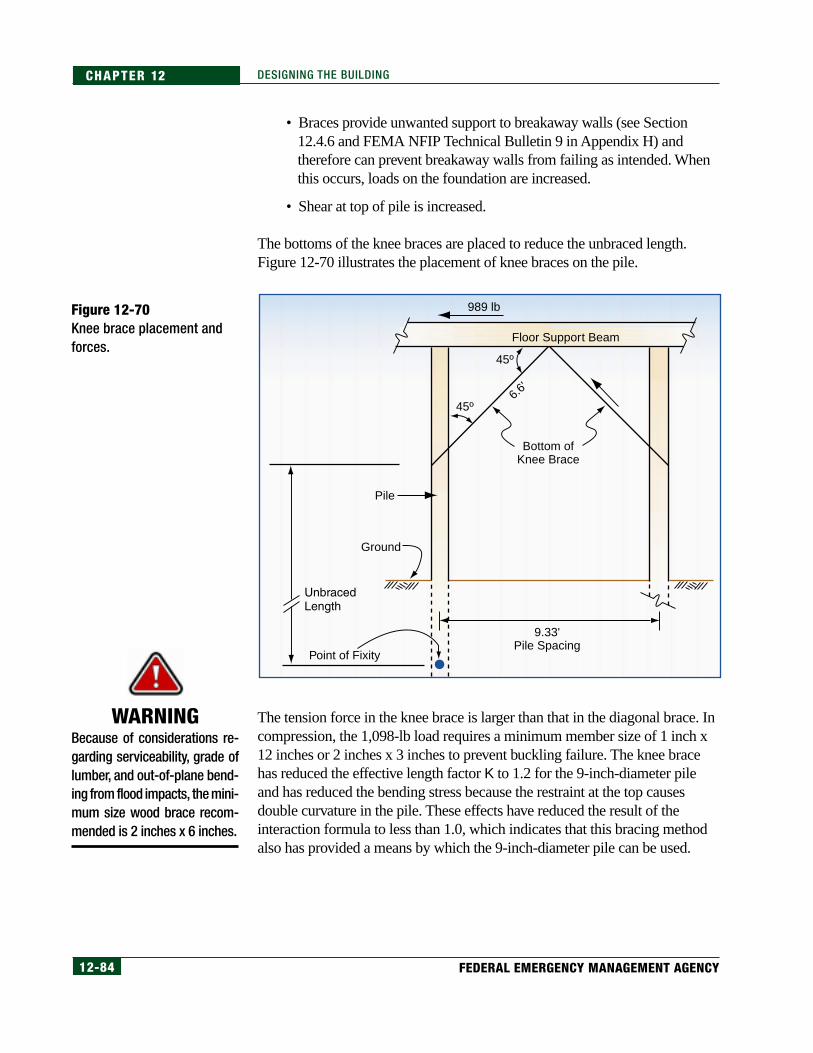
12-84 FEDERAL EMERGENCY MANAGEMENT AGENCY
CHAPTER 12 DESIGNING THE BUILDING
• Braces provide unwanted support to breakaway walls (see Section12.4.6 and FEMA NFIP Technical Bulletin 9 in Appendix H) andtherefore can prevent breakaway walls from failing as intended. Whenthis occurs, loads on the foundation are increased.
• Shear at top of pile is increased.
The bottoms of the knee braces are placed to reduce the unbraced length.Figure 12-70 illustrates the placement of knee braces on the pile.
The tension force in the knee brace is larger than that in the diagonal brace. Incompression, the 1,098-lb load requires a minimum member size of 1 inch x12 inches or 2 inches x 3 inches to prevent buckling failure. The knee bracehas reduced the effective length factor K to 1.2 for the 9-inch-diameter pileand has reduced the bending stress because the restraint at the top causesdouble curvature in the pile. These effects have reduced the result of theinteraction formula to less than 1.0, which indicates that this bracing methodalso has provided a means by which the 9-inch-diameter pile can be used.
9.33'Pile Spacing
6.6'
45º
45º
Bottom ofKnee Brace
Pile
989 lb
Ground
Floor Support Beam
Point of Fixity
Figure 12-70Knee brace placement andforces.
WARNINGBecause of considerations re-garding serviceability, grade oflumber, and out-of-plane bend-ing from flood impacts, the mini-mum size wood brace recom-mended is 2 inches x 6 inches.
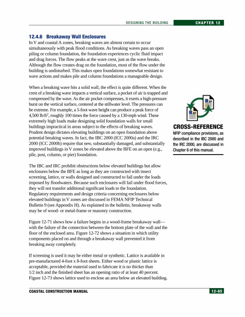
12-85COASTAL CONSTRUCTION MANUAL
CHAPTER 12DESIGNING THE BUILDING
12.4.6 Breakaway Wall EnclosuresIn V and coastal A zones, breaking waves are almost certain to occursimultaneously with peak flood conditions. As breaking waves pass an openpiling or column foundation, the foundation experiences cyclic fluid impactand drag forces. The flow peaks at the wave crest, just as the wave breaks.Although the flow creates drag on the foundation, most of the flow under thebuilding is undisturbed. This makes open foundations somewhat resistant towave actions and makes pile and column foundations a manageable design.
When a breaking wave hits a solid wall, the effect is quite different. When thecrest of a breaking wave impacts a vertical surface, a pocket of air is trapped andcompressed by the wave. As the air pocket compresses, it exerts a high-pressureburst on the vertical surface, centered at the stillwater level. The pressures canbe extreme. For example, a 5-foot wave height can produce a peak force of4,500 lb/ft2, roughly 100 times the force caused by a 130-mph wind. Theseextremely high loads make designing solid foundation walls for smallbuildings impractical in areas subject to the effects of breaking waves.Prudent design dictates elevating buildings on an open foundation abovepotential breaking waves. In fact, the IBC 2000 (ICC 2000a) and the IRC2000 (ICC 2000b) require that new, substantially damaged, and substantiallyimproved buildings in V zones be elevated above the BFE on an open (e.g.,pile, post, column, or pier) foundation.
The IBC and IRC prohibit obstructions below elevated buildings but allowenclosures below the BFE as long as they are constructed with insectscreening, lattice, or walls designed and constructed to fail under the loadsimposed by floodwaters. Because such enclosures will fail under flood forces,they will not transfer additional significant loads to the foundation.Regulatory requirements and design criteria concerning enclosures belowelevated buildings in V zones are discussed in FEMA NFIP TechnicalBulletin 9 (see Appendix H). As explained in the bulletin, breakaway wallsmay be of wood- or metal-frame or masonry construction.
Figure 12-71 shows how a failure begins in a wood-frame breakaway wall—with the failure of the connection between the bottom plate of the wall and thefloor of the enclosed area. Figure 12-72 shows a situation in which utilitycomponents placed on and through a breakaway wall prevented it frombreaking away completely.
If screening is used it may be either metal or synthetic. Lattice is available inpre-manufactured 4-foot x 8-foot sheets. Either wood or plastic lattice isacceptable, provided the material used to fabricate it is no thicker than1/2 inch and the finished sheet has an opening ratio of at least 40 percent.Figure 12-73 shows lattice used to enclose an area below an elevated building.
CROSS-REFERENCENFIP compliance provisions, asdescribed in the IBC 2000 andthe IRC 2000, are discussed inChapter 6 of this manual.

12-86 FEDERAL EMERGENCY MANAGEMENT AGENCY
CHAPTER 12 DESIGNING THE BUILDING
12.5 Step 4 – Develop Connections at Each Link
12.5.1 Connection ChoicesAlternatives for joining building components include the following:
• mechanical connectors such as those available from a variety ofmanufacturers
• fasteners such as nails, screws, bolts, pegs, and reinforcing steel
• connectors such as wood blocks
• alternative materials such as adhesives and strapping
Figure 12-72Hurricane Opal (1995),Florida. Utility penetrationsprevented this breakawaywall panel from breakingaway cleanly.
Figure 12-71Hurricane Hugo (1989), SouthCarolina. Typical failure modeof breakaway wall beneathan elevated building—failureof the connection betweenthe bottom plate of the walland the floor of theenclosed area.
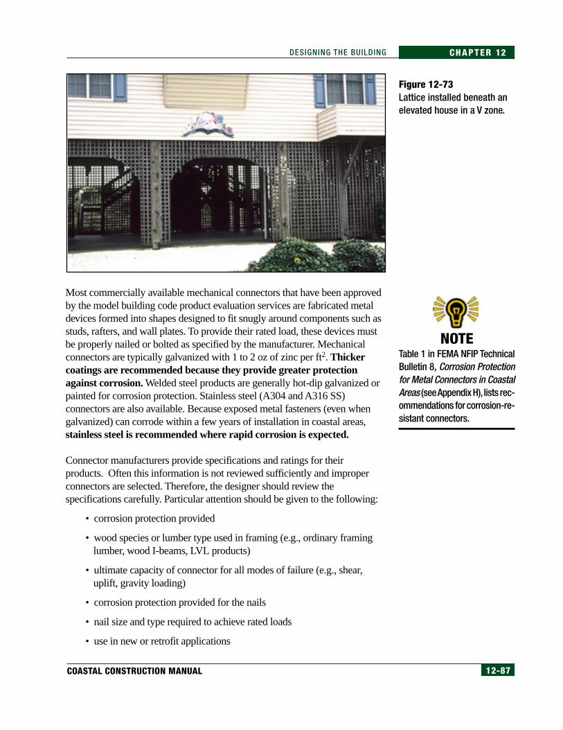
12-87COASTAL CONSTRUCTION MANUAL
CHAPTER 12DESIGNING THE BUILDING
Most commercially available mechanical connectors that have been approvedby the model building code product evaluation services are fabricated metaldevices formed into shapes designed to fit snugly around components such asstuds, rafters, and wall plates. To provide their rated load, these devices mustbe properly nailed or bolted as specified by the manufacturer. Mechanicalconnectors are typically galvanized with 1 to 2 oz of zinc per ft2. Thickercoatings are recommended because they provide greater protectionagainst corrosion. Welded steel products are generally hot-dip galvanized orpainted for corrosion protection. Stainless steel (A304 and A316 SS)connectors are also available. Because exposed metal fasteners (even whengalvanized) can corrode within a few years of installation in coastal areas,stainless steel is recommended where rapid corrosion is expected.
Connector manufacturers provide specifications and ratings for theirproducts. Often this information is not reviewed sufficiently and improperconnectors are selected. Therefore, the designer should review thespecifications carefully. Particular attention should be given to the following:
• corrosion protection provided
• wood species or lumber type used in framing (e.g., ordinary framinglumber, wood I-beams, LVL products)
• ultimate capacity of connector for all modes of failure (e.g., shear,uplift, gravity loading)
• corrosion protection provided for the nails
• nail size and type required to achieve rated loads
• use in new or retrofit applications
NOTETable 1 in FEMA NFIP TechnicalBulletin 8, Corrosion Protectionfor Metal Connectors in CoastalAreas (see Appendix H), lists rec-ommendations for corrosion-re-sistant connectors.
Figure 12-73Lattice installed beneath anelevated house in a V zone.
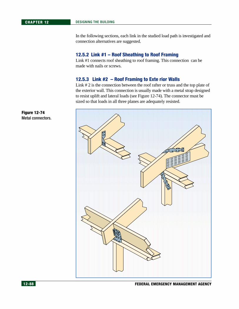
12-88 FEDERAL EMERGENCY MANAGEMENT AGENCY
CHAPTER 12 DESIGNING THE BUILDING
In the following sections, each link in the studied load path is investigated andconnection alternatives are suggested.
12.5.2 Link #1 – Roof Sheathing to Roof FramingLink #1 connects roof sheathing to roof framing. This connection can bemade with nails or screws.
12.5.3 Link #2 – Roof Framing to Exte rior WallsLink # 2 is the connection between the roof rafter or truss and the top plate ofthe exterior wall. This connection is usually made with a metal strap designedto resist uplift and lateral loads (see Figure 12-74). The connector must besized so that loads in all three planes are adequately resisted.
Figure 12-74Metal connectors.

12-89COASTAL CONSTRUCTION MANUAL
CHAPTER 12DESIGNING THE BUILDING
The loads at Link #2 (from Section 12.4.2) are as follows:
• uplift = 383 lb (from Table 12.7)
• lateral force in plane of the wall =286 lb (from page 12-41)
• normal force = 457 lb (from page 12-41)
The designer must specify connectors and their locations and capacities in theplans. A number of manufacturers supply mechanical connectors for use inresidential construction.
In a retrofit situation, it is possible to nail a connecting board to both the roofmember and the top plate of the wall. Figure 12-75 illustrates this connectionwith wood. The installation must be done carefully so that no wood splitsduring the installation of the nails. Wood splitting will significantly reduce thecapacity of the member in any of the primary directions. Each of the primaryloads can be resisted with 16d nails that each resist 224 lb in single shear[from 1997 NDS where shear value is (122)(1.6)(1.15)] and 85 lb inwithdrawal. For this connection, the uplift can be resisted by two 16d nailsand by two to four 16d nails in lateral and normal directions.
Figure 12-75 Board connected to both the roof member and the top plate of the wall.
Double Top Plate
Double Top Plate
Truss Members
Nails IntoTop Plate and Stud
Nails IntoTop Plate and Stud
Wall Stud Wall Stud
Wood Brace
Wood Brace
Rafter Roof Truss Roof
Rafter
MetalStrap
MetalStrap
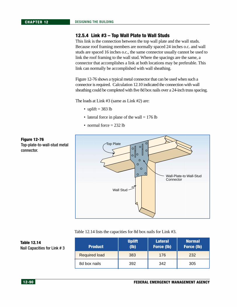
12-90 FEDERAL EMERGENCY MANAGEMENT AGENCY
CHAPTER 12 DESIGNING THE BUILDING
12.5.4 Link #3 – Top Wall Plate to Wall StudsThis link is the connection between the top wall plate and the wall studs.Because roof framing members are normally spaced 24 inches o.c. and wallstuds are spaced 16 inches o.c., the same connector usually cannot be used tolink the roof framing to the wall stud. Where the spacings are the same, aconnector that accomplishes a link at both locations may be preferable. Thislink can normally be accomplished with wall sheathing.
Figure 12-76 shows a typical metal connector that can be used when such aconnector is required. Calculation 12.10 indicated the connection with wallsheathing could be completed with five 8d box nails over a 24-inch truss spacing.
The loads at Link #3 (same as Link #2) are:
• uplift = 383 lb
• lateral force in plane of the wall = 176 lb
• normal force = 232 lb
Table 12.14 lists the capacities for 8d box nails for Link #3.
Figure 12-76Top-plate-to-wall-stud metalconnector.
Table 12.14Nail Capacities for Link # 3
Top Plate
Wall-Plate-to Wall-StudConnector
Wall Stud
NormalForce (lb)
LateralForce (lb)
Uplift(lb)Product
Required load
8d box nails
383
392
176
342
232
305

12-91COASTAL CONSTRUCTION MANUAL
CHAPTER 12DESIGNING THE BUILDING
12.5.5 Link #4 – Wall Stud to Window HeaderThe connection method and the loads required at this connection are the sameas those used at Link #3.
12.5.6 Link #5 – Window Header to Exterior WallThis link is the connection between the end of the window header and thewall studs. This connector will normally have to be placed flat against theframing, so it will be in the shape of a strap. The connector must be sized sothat loads in all three planes are adequately resisted.
The loads at Link # 5 (from Section 12.4.2) are:
• uplift = 731 lb (from page 12-45)
• lateral force in plane of the wall is distributed into shearwall
• normal force = 449 lb (from Calculation 12.11) (Use end nails throughstud into header.)
12.5.7 Link #6 – Wall to Floor FramingThis link is the connection between the bottom of the wall framing and firstfloor. The connector used here is also the shearwall holddown connector. It isbolted to a stud (or more than one stud) and through the floor framing into thebeam (as in the case study house) or, in a multi-story house, to the wall below.This connector must be sized to resist tension. Figure 12-77 shows ashearwall holddown connector. The uplift load at this holddown is 4,064 lb(from Calculation 12.15).
Figure 12-77Shearwall holddownconnector.
Wall Stud
Wall Stud
Band Joist
Bottom Plate
Pile
Two-MemberFloor Support
Beam
Shearwall HolddownConnector Bolted Through Stud

12-92 FEDERAL EMERGENCY MANAGEMENT AGENCY
CHAPTER 12 DESIGNING THE BUILDING
12.5.8 Link #7 – Floor Framing to Support BeamThis link is the connection between the floor framing and the floor supportbeam and does not include the shearwall overturning uplift. This connectioncan be made with either a metal connector (see Figure 12-51) or a block ofwood installed between the floor support beam and nailed to the floor joists(see Figure 12-52). This connector must be sized so that loads in all threeplanes are adequately resisted.
The loads at Link #7 (from Section 12.4.2) are:
• uplift – 4,064 lb
• lateral force in plane of the wall – 443 lb (from page 12-53)
• normal force – 168 lb (from page 12-53)
12.5.9 Link #8 – Floor Support Beam to Pile FoundationThe connection between the beam and the top of the pile has already beendiscussed. This connection is normally completed with hex head bolts (boltsinstalled through the beam and top of the pile). When this connection is madeby notching the pile to provide a “seat” for the beam, the pile is oftenovernotched. The top of the pile at the cut is a failure plane in shear.
For the case study example problem, the lateralload at the pile top is 989 lb. When the top of thepile is held rigidly by bracing, the load could shearoff the top of the pile. Using guidelines from theNTPC (1995), the allowable shear stress is(F
v)(C
d)(C
pt) = (110 lb/in2)(1.6)(0.90)
= 158.4 lb/in2 (and as noted on page 12-66, themaximum shear stress is higher than this averageshear stress)
The minimum area of the pile required to resistshear failure is 989 lb(1.5 factor for rectangularshape)/(158.4) lb/in2. The minimum area = 9.4 in2.
The area of a 9-inch-diameter pile is 63.62 in2, so the minimum area requiredis 15 percent of the pile area. Overnotching to provide a beam “seat” doesincrease the risk of shear failure in the pile. Figure 12-78 illustrates failure ofa pile that has been overnotched. Reinforcing the pile at the overnotchedsection with steel plates on both sides of the pile is an acceptable method ofincreasing the shear capacity at this critical point. This detail must, however,be carefully designed.
WARNINGOvernotching of pilings duringconstruction is a common prob-lem. Designers should specifymaximum pile notching depths.
[12.23]
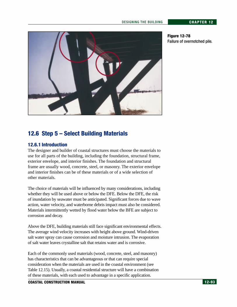
12-93COASTAL CONSTRUCTION MANUAL
CHAPTER 12DESIGNING THE BUILDING
12.6 Step 5 – Select Building Materials
12.6.1 IntroductionThe designer and builder of coastal structures must choose the materials touse for all parts of the building, including the foundation, structural frame,exterior envelope, and interior finishes. The foundation and structuralframe are usually wood, concrete, steel, or masonry. The exterior envelopeand interior finishes can be of these materials or of a wide selection ofother materials.
The choice of materials will be influenced by many considerations, includingwhether they will be used above or below the DFE. Below the DFE, the riskof inundation by seawater must be anticipated. Significant forces due to waveaction, water velocity, and waterborne debris impact must also be considered.Materials intermittently wetted by flood water below the BFE are subject tocorrosion and decay.
Above the DFE, building materials still face significant environmental effects.The average wind velocity increases with height above ground. Wind-drivensalt water spray can cause corrosion and moisture intrusion. The evaporationof salt water leaves crystalline salt that retains water and is corrosive.
Each of the commonly used materials (wood, concrete, steel, and masonry)has characteristics that can be advantageous or that can require specialconsideration when the materials are used in the coastal environment (seeTable 12.15). Usually, a coastal residential structure will have a combinationof these materials, with each used to advantage in a specific application.
Figure 12-78Failure of overnotched pile.

12-94 FEDERAL EMERGENCY MANAGEMENT AGENCY
CHAPTER 12 DESIGNING THE BUILDING
Table 12.15General Guidance forSelection of Materials –Advantages and SpecialConsiderations
Material Special ConsiderationsAdvantages
• Generally available and commonly used
• With proper design, can generally be used in most structural applications
• Variety of products available
• Can be treated to resist decay
• Used for larger forces than wood can resist
• Can span long distances
• Can be coated to resist corrosion
• Resistant to corrosion if reinforcing is properly protected
• Good material for compressive loads
• Can be formed into a variety of shapes
• Pre-stressed members have high load capacity
• Resistant to corrosion if reinforcing is properly protected
• Good material for compressive loads
• Material commonly used in residential construction
• Easily over-cut, over-notched, and over-nailed
• Many designs done by "rule-of-thumb"
• Requires special treatment and continued maintenance to resist decay and damage from termites and marine borers
• Requires protection to resist weathering
• Subject to warping and deterioration
• Not corrosion-resistant
• Heavy and not easily handled and fabricated by carpenters
• May require special connections such as welding
• Salt water infiltration into concrete cracks will cause reinforcing steel corrosion
• Pre-stressed members require special handling
• Water intrusion and freeze-thaw cause deterioration and spalling
• Not good for beams and girders
• Water infiltration into cracks will cause reinforcing steel corrosion
• Requires reinforcement to resist loads in coastal areas
Wood
ReinforcedConcrete
Masonry
Steel

12-95COASTAL CONSTRUCTION MANUAL
CHAPTER 12DESIGNING THE BUILDING
12.6.2 Selection of Materials for Foundations and EnclosuresBelow the DFE
The use of flood-resistant materials below the BFE is covered in FEMANFIP Technical Bulletin 2 (see Appendix H). The introduction in thisbulletin indicates that “All construction below the lowest floor is susceptibleto flooding and must consist of flood-resistant materials. Uses of enclosedareas below the lowest floor in a residential building are limited to parking,access, and limited storage—areas that can withstand inundation byfloodwater without sustaining significant structural damage.” The IBC 2000and IRC 2000 require that all new construction and substantialimprovements in the Special Flood Hazard Area be constructed withmaterials resistant to flood damage.
Compliance with these requirements in coastal areas means that the onlybuilding elements that will be below the BFE include the following:
• foundations – either treated wood, concrete or steel piles, concrete ormasonry piers, or concrete, masonry, or treated wood walls
• breakaway walls
• enclosures used for parking, building access, or storage below elevatedbuildings
• garages in enclosures under elevated buildings or attached to buildings
Material choices for these elements are limited to the following:
• pressure-treated lumber, 0.40 CCA or equivalent (see Appendix J andreferences listed at the end of this chapter for additional information onwood preservatives)
• naturally decay-resistant lumber
• concrete – 5,000 lb/in2 minimum compressive strength recommendedin coastal environments, with a 0.40 water-cement ratio
• masonry – reinforced and fully grouted in coastal environments
• steel – must resist corrosion
• closed-cell foam insulation
• other flood-resistant materials approved by local building officials
Each of these materials has characteristics that can be advantageous or thatcan require special consideration when the materials are used for variousbuilding elements. Some of these are presented in Table 12.16. Additionalinformation about material selection for various locations in the building andfor various uses is included in Appendix J.
NOTEAlthough the NFIP regulations,IBC 2000 (ICC 2000a), and IRC2000 (ICC 2000b) specify thatflood-resistant materials beused below the BFE, thismanual recommends thatflood-resistant materials beused below the DFE.
CROSS-REFERENCENFIP compliance provisions, asdescribed in the IBC 2000 andthe IRC 2000, are discussed inChapter 6 of this manual.
CROSS-REFERENCETable 9.6 in Chapter 9 listssample flood insurance premi-ums for buildings in which thelowest floor is below the BFEand in which there is an enclo-sure below the BFE.
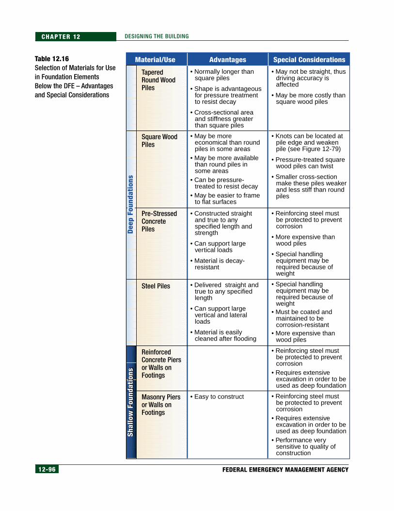
12-96 FEDERAL EMERGENCY MANAGEMENT AGENCY
CHAPTER 12 DESIGNING THE BUILDING
Table 12.16Selection of Materials for Usein Foundation ElementsBelow the DFE – Advantagesand Special Considerations
Material/Use Special ConsiderationsAdvantages
• Normally longer than square piles
• Shape is advantageous for pressure treatment to resist decay
• Cross-sectional area and stiffness greater than square piles
• May be more economical than round piles in some areas
• May be more available than round piles in some areas
• Can be pressure-treated to resist decay
• May be easier to frame to flat surfaces
• Constructed straight and true to any specified length and strength
• Can support large vertical loads
• Material is decay- resistant
• Delivered straight and true to any specified length
• Can support large vertical and lateral loads
• Material is easily cleaned after flooding
• Easy to construct
• May not be straight, thus driving accuracy is affected
• May be more costly than square wood piles
• Knots can be located at pile edge and weaken pile (see Figure 12-79)
• Pressure-treated square wood piles can twist
• Smaller cross-section make these piles weaker and less stiff than round piles
• Reinforcing steel must be protected to prevent corrosion
• More expensive than wood piles
• Special handling equipment may be required because of weight
• Special handling equipment may be required because of weight
• Must be coated and maintained to be corrosion-resistant
• More expensive than wood piles
• Reinforcing steel must be protected to prevent corrosion
• Requires extensive excavation in order to be used as deep foundation
• Reinforcing steel must be protected to prevent corrosion
• Requires extensive excavation in order to be used as deep foundation
• Performance very sensitive to quality of construction
Tapered Round WoodPiles
Square WoodPiles
ReinforcedConcrete Piersor Walls onFootings
Pre-StressedConcrete Piles
Masonry Piersor Walls onFootings
Steel Piles
Shal
low
Fou
ndat
ions
Shal
low
Fou
ndat
ions
Dee
p Fo
unda
tion
s
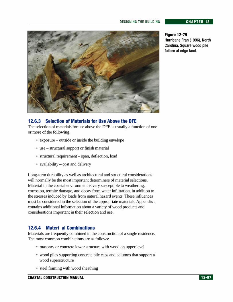
12-97COASTAL CONSTRUCTION MANUAL
CHAPTER 12DESIGNING THE BUILDING
12.6.3 Selection of Materials for Use Above the DFEThe selection of materials for use above the DFE is usually a function of oneor more of the following:
• exposure – outside or inside the building envelope
• use – structural support or finish material
• structural requirement – span, deflection, load
• availability – cost and delivery
Long-term durability as well as architectural and structural considerationswill normally be the most important determiners of material selections.Material in the coastal environment is very susceptible to weathering,corrosion, termite damage, and decay from water infiltration, in addition tothe stresses induced by loads from natural hazard events. These influencesmust be considered in the selection of the appropriate materials. Appendix Jcontains additional information about a variety of wood products andconsiderations important in their selection and use.
12.6.4 Materi al CombinationsMaterials are frequently combined in the construction of a single residence.The most common combinations are as follows:
• masonry or concrete lower structure with wood on upper level
• wood piles supporting concrete pile caps and columns that support awood superstructure
• steel framing with wood sheathing
Figure 12-79Hurricane Fran (1996), NorthCarolina. Square wood pilefailure at edge knot.

12-98 FEDERAL EMERGENCY MANAGEMENT AGENCY
CHAPTER 12 DESIGNING THE BUILDING
For the designer of coastal buildings, the important design considerationswhen combining materials include:
1. There must be material compatibility so that corrosion is not causedby the contact of dissimilar metals in the presence of salt and moisture.Appendix J addresses a possible problem with galvanized fasteners andhardware in contact with certain types of treated wood.
2. Connecting the materials together is crucial. The connector mustbe properly embedded (if into concrete or masonry) and placed sothat alignment and vertical or horizontal load path continuity aremaintained. Altering a connector location after it has been cast intoconcrete or grout is a difficult and expensive task.
3. Material combinations used for the same building add the complexityof additional skills being required to construct the project. This isnormally of more concern to the builder than to the designer, but mayimpact decisions regarding which materials will be acceptable. Figure12-80 shows a coastal house being constructed with ordinary woodpiles that support a welded steel frame that will be used as the floorframe support beams.
4. Material properties such as stiffness of one material relative toanother will affect movement or deflection of one material relativeto the other. This difference in material behavior can affect theresultant damage to the building. For example, movement thatoccurs in a wood-frame building during high wind can fail masonrypiers because masonry is less flexible than wood and will fail withsmall deflection.
Figure 12-80House being constructedwith a steel frame onwooden piles.

12-99COASTAL CONSTRUCTION MANUAL
CHAPTER 12DESIGNING THE BUILDING
12.6.5 Fire Safety ConsiderationsConstruction of multi-family coastal dwellings that must withstand naturalhazards and meet the building code requirements for adequate fire separationpresents some challenges. In multi-family buildings, the IBC 2000 and IRC2000 require that the common walls between living units be constructed ofmaterials that provide a minimum of 2-hour fire resistance. The code requiresthat the units be constructed such that if a fire were to occur in one unit, thestructural frame of that unit would collapse within itself and not affect eitherthe structure or the fire resistance of adjacent units.
For townhouse-like units, the common framing method is to use the front andrear walls for the exterior load-bearing walls so that firewalls can be placedbetween the units. If these walls are also used as the support for the floorframing, the floor support beams must be supported by the side walls (or sidewall support structure such as piles). This beam orientation may make thestructure more vulnerable to flood damage. Figure 12-81 illustrates the framingsystem for a series of townhouses and the potential difficulties in framing theseunits to minimize flood and wind damage.
Figure 12-81Townhouse framing system.
Pile-SupportedBuildings
Shoreline
Primary Direction of Flood Forces
Floor BeamsParallel toShore
Piles
Separation Requiredby Fire Code Provisions
Plan Viewof Townhouse
Foundation
Floor JoistDirection

12-100 FEDERAL EMERGENCY MANAGEMENT AGENCY
CHAPTER 12 DESIGNING THE BUILDING
The figure suggests several design difficulties that must be overcome. Thesedifficulties include, but are not limited to the following:
1. The floor support beams are parallel to the shore and perpendicular tothe expected flow, and may therefore create an obstruction during agreater than design flood event.
2. The fire separation between the units makes structural rigiditydifficult to achieve because the interior walls between townhouseunits cannot be attached to the framing system and used for support.Therefore, the transfer of lateral loads to the foundation, particularlyfor multi-directional loads from wind or earthquake forces, isdifficult to achieve.
3. The exposed undersides of buildings elevated on an open foundation(e.g., pile, pier, post, or column) must be protected from fire with a 2-hour rated material. Where sheathing is desired on the underside ofthe floor framing—for example, in a below-building enclosure usedfor parking, storage, or building access—the use of fire-resistantgypsum board will comply with the requirement for fire protection;however, gypsum board is not a flood-resistant material. A betterapproach would be to use cement-fiber board, which has a greaterresistance to damage from flood waters. If the building designrequires fire separation and the fire-protection material is not flood-resistant (e.g., gypsum board), larger wood framing members or othertechniques may be required in order to meet the competing demandsof flood- and fire-resistance.
4. The requirement for separation of the foundation elementsbetween townhouse units makes structural rigidity in the directionparallel to the shore difficult to achieve. If the houses in Figure 12-81 were located in a seismic hazard area, the designer might wantto place a shearwall or diagonal bracing in the direction parallel tothe shore (i.e., perpendicular to the primary flood flow direction).Shearwall segments or diagonal bracing will provide rigidity, butwhen they are constructed below the first-floor framing (and thusbelow the DFE) and perpendicular to the expected flood flow, theywill create an obstruction below the DFE. The designer shouldconsult FEMA NFIP Technical Bulletin 5, Free of ObstructionRequirements for Buildings Located in Coastal High HazardAreas (see Appendix H) for information about the types ofconstruction that constitute an obstruction.
Designers should consult local building officials for guidance about how tocreate a design compatible with both fire and natural hazard designrequirements. Understanding local requirements will influence how thedesigner resolves potential conflicts between various code requirements.
NOTEConsult the local building codeor building official to deter-mine how to resolve the con-flict between fire-resistantconstruction and flood-resis-tant construction.

12-101COASTAL CONSTRUCTION MANUAL
CHAPTER 12DESIGNING THE BUILDING
12.6.6 CorrosionModern construction techniques often rely heavily on metal fasteners andconnectors to resist the forces of various coastal hazards. To be successful, theseproducts must have lifetimes comparable to those of the other materials used forconstruction. The metal materials in common use have proved to have anadequate lifetime in most inland applications. However, for some uses nearsaltwater coastlines, corrosion has been found to drastically shorten the lifetimeof standard fasteners and connectors. Corrosion is one of the mostunderestimated hazards affecting the overall strength and lifetime of coastalbuildings. To be successful, hazard-resistant buildings must match the corrosionexposure of each component with the proper corrosion-resistant material.Although standard materials may not have sufficient corrosion resistance forsome uses in coastal buildings, a variety of corrosion-resistant materials andtechniques are readily available, often at a small increase in cost.
FEMA NFIP Technical Bulletin 8, Corrosion Protection for MetalConnectors in Coastal Areas, represents the current state of knowledge andresearch concerning this subject. This bulletin is included in Appendix H.
12.6.7 Additional Environmental ConsiderationsIn addition to water intrusion and possible resulting decay, several otherenvironmental factors must be considered in the selection of materials to beused in coastal buildings. The coastal environment is extremely harsh, andmaterials should be selected that will not only provide protection from theharsh elements, but also require minimal maintenance. The followingenvironmental factors will be discussed:
• sun (heat and ultraviolet [UV] radiation)
• wind-driven rain
12.6.7.1 SunBuildings at or near the coast are typically exposed to extremes of sun, whichproduces high heat and UV radiation. This exposure creates the following effects:
• The sun will bleach out many colors.
• The heat will build up in enclosed spaces like attics so the design mustconsider ways to reduce the heat buildup.
• The heat and UV will shorten the life of many organic materials suchas asphalt roof shingles.
• The heat and UV affect the life of sealants, protective materials placedon siding, and exterior wood used for decks, walkways, and otherexternal components.
NOTESee FEMA NFIP Technical Bul-letin 8 (Appendix H) for addi-tional information about corro-sion of metal connectors incoastal construction.
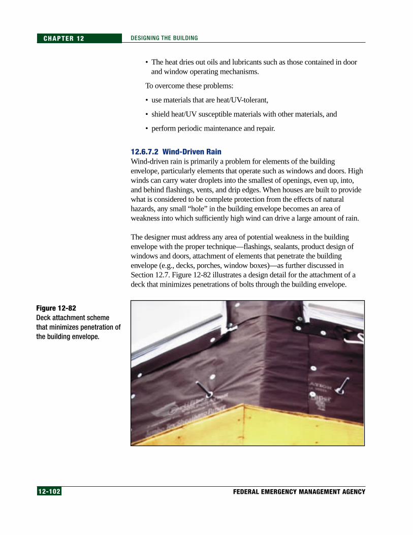
12-102 FEDERAL EMERGENCY MANAGEMENT AGENCY
CHAPTER 12 DESIGNING THE BUILDING
• The heat dries out oils and lubricants such as those contained in doorand window operating mechanisms.
To overcome these problems:
• use materials that are heat/UV-tolerant,
• shield heat/UV susceptible materials with other materials, and
• perform periodic maintenance and repair.
12.6.7.2 Wind-Driven RainWind-driven rain is primarily a problem for elements of the buildingenvelope, particularly elements that operate such as windows and doors. Highwinds can carry water droplets into the smallest of openings, even up, into,and behind flashings, vents, and drip edges. When houses are built to providewhat is considered to be complete protection from the effects of naturalhazards, any small “hole” in the building envelope becomes an area ofweakness into which sufficiently high wind can drive a large amount of rain.
The designer must address any area of potential weakness in the buildingenvelope with the proper technique—flashings, sealants, product design ofwindows and doors, attachment of elements that penetrate the buildingenvelope (e.g., decks, porches, window boxes)—as further discussed inSection 12.7. Figure 12-82 illustrates a design detail for the attachment of adeck that minimizes penetrations of bolts through the building envelope.
Figure 12-82Deck attachment schemethat minimizes penetration ofthe building envelope.

12-103COASTAL CONSTRUCTION MANUAL
CHAPTER 12DESIGNING THE BUILDING
12.7 Design of the Building EnvelopeThe building envelope comprises the roof covering, exterior wall covering,and exterior doors and windows. For buildings elevated on open foundations,the floor is also considered a part of the envelope .
To avoid injury and minimize damage to a building and its contents, goodstructural system performance is critical; however, it does not ensure occupantor building protection. Good performance of the building envelope andexterior-mounted mechanical and electrical equipment is also necessary.Satisfactory building envelope performance is critical for buildings exposed tohigh-wind and wildfire hazards.
Satisfactory performance of the envelope depends on suitable design,materials, application, maintenance, and repair. Of these, design is the keyelement. Although design inadequacies frequently cannot be compensatedfor by the other four elements, good design (to some extent) cancompensate for other inadequacies.
Breaching of the building envelope and subsequent water infiltration hashistorically been the predominant cause of damage to buildings and theircontents during high-wind events. Breaching includes catastrophic failure(e.g., loss of the roof covering or windows) as well as water infiltrationthrough small openings at walls, windows, doors, or the roof. Waterinfiltration also occurs during high winds because wind-driven rain willpenetrate into even the smallest opening. Preventing this type of damagerequires the application of a high-quality sealant around components suchas windows and doors. Other openings that must be properly sealedinclude mechanically attached roof or wall penetrations such as exhaustfans and vents.
Building envelope components have also been the predominant source ofwindborne missiles generated from damaged buildings. Close design attentionshould be given to buildings in special wind regions (see Figure 11-18, inChapter 11) or in areas where the basic wind speed is greater than 90 mph(3-sec peak gust).
Building integrity in earthquakes also is dependent on the performance of thebuilding envelope, particularly the integrity of roof-to-wall connections anddiaphragm-to-wall connections and detailing. Residential buildings havehistorically performed very well when the structural integrity of thesecomponents of the building envelope has been maintained.
In addition, poor resistance of building envelopes to wildfires has historicallyresulted in building losses as illustrated in Figure 12-83.
NOTESpecial attention to the designof the building envelope mustbe given to buildings located inareas subject to wind speedsgreater than 90 mph (3-secpeak gust).

12-104 FEDERAL EMERGENCY MANAGEMENT AGENCY
CHAPTER 12 DESIGNING THE BUILDING
Basic design issues and general good practices that are applicable to allresidential design are not addressed in this section. Rather, this section buildson the basics by addressing the special design considerations related tobuildings susceptible to natural hazards. It provides recommendationsregarding doors, floors, roofs, walls, and windows. Flooding influence on thebuilding envelope is not addressed, because it is assumed that the envelopewill not be inundated by water; however, envelope resistance to wind-drivenrain is addressed. The recommended measures taken to protect against wind-driven rain should also be adequate to protect against wave spray.
12.7.1 Floors for Elevated Buildings
12.7.1.1 Corrosion and Wave SprayFor buildings near the ocean, sheathing the underside of the bottom-floor joists ortrusses helps minimize corrosion of framing connectors and fasteners. Thesheathing also protects insulation installed between the joists/trusses from wavespray. (If fiberglass insulation is installed, the paper or foil face should be installedadjacent to the underside of the floor decking, or the insulation should be unfacedso that downward water vapor migration is not impeded.) For long-termdurability, exterior grade sheathing is recommended for the exposed sheathingand it should be fastened with stainless steel or hot-dip galvanized nails or screws.
12.7.1.2 High WindsFor buildings in high-wind areas, if sheathing is applied to the underside ofjoists or trusses, its attachment should be specified in order to avoid blowoff.
12.7.1.3 WildfiresFor buildings in areas prone to wildfires, sheathing the underside of joists ortrusses with a fire-resistant material such as cement-fiber panels is
NOTEFor A-zone buildings elevated onsolid walls with openings, anumber of manufacturers pro-duce vents that reduce heat lossin cold-weather environmentsbut still allow the entry and exitof flood waters.
Figure 12-83The fire-resistant walls androof of this house helped itsurvive a wildfire whilesurrounding houses weredestroyed. Photographcourtesy of Decra RoofingSystems.
12-105COASTAL CONSTRUCTION MANUAL
CHAPTER 12DESIGNING THE BUILDING
recommended. Cement-fiber panels should be attached with stainless steel orhot-dip galvanized screws.
12.7.2 Exterior Walls and SoffitsHigh winds and wildfires are the natural hazards that can cause the greatestdamage to exterior wall systems. Seismic events can also damage heavy wallsystems or coverings. Although hail can damage walls, significant damage isnot common.
A variety of systems can be used for wall construction. The following wallcoverings are commonly used over wood-frame construction: aluminumsiding, cement-fiber panels or siding, exterior insulating finishing system(EIFS), stucco, vinyl siding, sawn wood siding boards, and wood panel siding.Concrete or masonry wall construction may also be used. These systems arediscussed in the following sections.
12.7.2.1 High WindsThe discussion of air-permeable roof coverings in Section 12.7.5 is alsoapplicable to air-permeable wall coverings such as siding. Research on specialpressure coefficients has not been conducted for air-permeable wall claddings.Therefore, according to ASCE 7, these claddings have to be designed for thefull wind load. Wind-load resistance of non-load-bearing walls, wall coverings,and soffits should be based on testing in accordance with ASTM E 1233. Wallsand soffits must be designed to resist positive and negative wind pressure.
Siding, panels (e.g., textured plywood), and stucco over masonry and concretetypically perform well during high winds. More blowoff problems have beenexperienced with vinyl siding than with other siding or panel materials. Aluminumand cement-fiber siding problems have also occurred. The key to the successfulperformance of siding and panel systems is attachment with a sufficient number ofproper corrosion-resistant fasteners (based on design loads and tested resistance)that are correctly located. Blowoff of stucco applied directly to concrete walls (i.e.,wire mesh was not applied over the concrete) has occurred. This problem can beavoided by leaving the concrete exposed or painted.
A secondary line of protection against wind-driven water infiltration (e.g., anair-barrier film) is recommended underneath wall coverings. Designers shouldspecify that horizontal laps be installed so that water is allowed to drain fromthe wall (i.e., the top sheet should lap over the bottom sheet so that waterrunning down the sheets remains on their outer face). The bottom of thesecondary protection needs to be detailed to allow drainage.
EIFS can be applied over wood-frame, concrete, or masonry construction. TheEIFS assembly is composed of several types of materials. Some of the layers are
NOTEThroughout this manual, refer-ences to ASTM standards arebased on the Annual Book ofASTM Standards (ASTM 1998).

12-106 FEDERAL EMERGENCY MANAGEMENT AGENCY
CHAPTER 12 DESIGNING THE BUILDING
adhered to one another, and one or more of the layers is typically mechanicallyattached to the wall. If mechanical fasteners are used, they need to be correctlylocated, of the proper type, and of sufficient number (based on design loads andtested resistance). Failures have been observed where the rated wind load capacityof the fasteners was not sufficient for a design event. Proper application of thecomponents that are adhered together is also necessary to avoid blowoff. It isstrongly recommended that if EIFS is used, it be designed with a drainagesystem that allows for dissipation of water leaks.
Punctures of EIFS by windborne debris are also common in high-windevents. EIFS must be installed on a solid substrate such as plywood in orderto provide enhanced resistance to missile penetration and thus occupantprotection. A minimum plywood thickness of 15/32-inch is recommended.
Concrete and masonry walls (or veneers) typically provide excellentwindborne missile resistance provided they are adequately designed andconstructed to resist the wind load.
Durability: To avoid corrosion problems, stainless steel or hot-dip galvanizedfasteners (preferable heavy-duty hot dip galvanized) are recommended forbuildings located within 3,000 feet of an ocean shoreline. If air can freelycirculate in a cavity (e.g., above a soffit), access panels should be provided socomponents within the cavity can be periodically observed for corrosion.
In areas with severe termite problems, if wood is specified, it should bepressure-treated. See Appendix J for additional information.
12.7.2.2 WildfiresFor buildings in areas prone to wildfires, concrete, masonry, stucco, orcement-fiber panels or siding offer the greatest protection. If one of thesewall surfaces is specified, a fire-resistive system should also be specified forsoffits (e.g., stucco or cement-fiber).
Gable and soffit vents should have openings covered with wire mesh that hasopenings no greater than 1/4 inch, in order to inhibit the entry of burningbrands. For added protection, noncombustible hinged shutters that canquickly be placed in the closed position could be designed and installed.
12.7.2.3 SeismicWhere required by code, concrete and masonry walls (or veneers) need to bedesigned for the seismic load. When a heavy covering such as stucco, cement-fiberpanels or siding, or brick veneer, is specified, the seismic design should account forthe added weight of the material, and its connection to the base material in the caseof veneer. Inadequate connection of veneer material to the base substrate has beena problem in past earthquakes and can result in a life safety hazard.
WARNINGThere have been documentedproblems with deterioration ofwall sheathing in EIFS systemsthat are non-drainable. The useof these systems has been re-stricted in some jurisdictions.The designer should consultwith local authorities to deter-mine whether such restrictionsexist, and what their effect maybe on design and construction.

12-107COASTAL CONSTRUCTION MANUAL
CHAPTER 12DESIGNING THE BUILDING
Some non-ductile coverings such as stucco and cement-fiber products can becracked or spalled during seismic events. If these coverings are specified inareas prone to large ground motion accelerations, the structural sheathingbehind the covering should be designed with additional stiffness to minimizedamage to the wall covering.
12.7.2.4 FlashingsPoor performance of flashing and water intrusion protection is a commonproblem in many coastal homes. In areas that frequently experience strongwinds, enhanced flashing details are recommended. Enhancements includeuse of flashings that have extra-long flanges, and use of sealant and tapes.General guidance is offered below, but it is recommended that designersalso attempt to determine what type of flashing details have successfullybeen used in the area where the residence will be constructed.
Flashing design should recognize that wind-driven water can be pushedvertically. The height to which water can be pushed increases with windspeed. Water can also migrate vertically and horizontally by capillary actionbetween layers of materials (e.g., between a flashing flange and housewrap).
Conceptually, the exterior siding should not be thought of as the only barrierto water intrusion. The housewrap (if used), flashings, and underlaymentmust be used to shed and direct water away from openings in the buildingenvelope. The overriding principle of successful water diversion is to installthe layers of building materials correctly so that water can not get behind anyone layer and into an opening.
• Roof/wall flashing: Where enhanced protection is desired, use stepflashing that has a 2- to 4-inch-longer vertical leg than normal.Alternatively (or for a more conservative design, in addition to thelong leg), tape the top of the vertical flashing to the wall sheathingwith 4-inch-wide self-adhering modified bitumen roof tape (applyabout 1 inch of tape on the metal flashing, 3 inches on the sheathing).Extend the housewrap over the flashing in the normal fashion. Do notseal the housewrap to the flashing—if water reaches the housewrapfurther up the wall, it needs to be able to drain out at the bottom of thewall. Figure 12-84 illustrates a good roof/wall flashing detail. Thisdetail has been used successfully by a builder on the Delaware coast.
• Window flashings: For windows with nailing flanges, apply agenerous bead of butyl sealant to the wall sheathing before setting thewindow. Place the sealant inward of the fasteners. At sheathing joints,place sealant over the joint, from the window opening out past theflange. Place the housewrap over the head trim flashing, and tape theflange to the housewrap with duct tape or modified bitumen roof tapeas illustrated in Figure 12-85.
NOTEHousewrap is a material used onthe exterior skin of the houseprior to siding installation that isprimarily intended to reduce airinfiltration into the building.
CROSS-REFERENCEThe designer should consultNail-On-Windows, Installation &Flashing Procedures for Win-dows & Sliding Glass Doors(Bateman 1995) for additionalinformation.

12-108 FEDERAL EMERGENCY MANAGEMENT AGENCY
CHAPTER 12 DESIGNING THE BUILDING
12.7.3 Doors and Door AssembliesHigh winds and wildfires are the natural hazards that present the greatestthreat to exterior doors.
Figure 12-85Window flashing detail.Courtesy of Journal of LightConstruction.
Figure 12-84 Roof/wall flashing detail. Courtesy of Journal of Light Construction.
Step Flashing
Vertical Leg
Roof Tape
Housewrap (Do Not Attach toRoof Tape)
Underlayment
Roof Sheathing
RoofingWall
Sheathing3"
1"
Head Trim
Window Flange
Head Trim Flashing
Slice Housewrap andInsert Flashing Behind;Tape Seam
Butyl Sealant
Housewrap
Tape

12-109COASTAL CONSTRUCTION MANUAL
CHAPTER 12DESIGNING THE BUILDING
12.7.3.1 High WindsLoads and resistance: The door assembly (i.e., door, hardware, frame, andframe attachment to the wall) should be of sufficient strength to resist positiveand negative design wind pressures (see Section 11.8 and the Wind LoadExample Problem on page 11-45). The assembly should be specified tocomply with wind load testing in accordance with ASTM E 1233. (Note:ASTM E 330 is the most commonly used method to evaluate doorassemblies; however, because E 1233 is a cyclic test method, whereas E 330is a static test, E 1233 is the preferred test method, particularly in hurricane-prone areas.) It is important to specify frame attachment to the wall, either byperformance or prescriptive criteria, as inadequate frame attachment due tolack of design guidance is a common problem.
Except for glazing, doors typically do not need to be resistant to loads fromhurricane-generated windborne missiles. If a door is hit with a missile, themissile may penetrate the door, but, in most cases, the missile opening willnot be large enough to result in significant water infiltration problems or in asubstantial increase in internal pressure. For information on glazing in doors,see Section 12.7.4.2. If enhanced missile resistance of solid doors is desiredfor occupant protection, specify door assemblies that have demonstratedcompliance with testing discussed in Section 12.7.4.2.
Durability: To avoid corrosion problems with metal doors or frames,aluminum or galvanized steel units are recommended for buildings locatedwithin 3,000 feet of an ocean shoreline. Stainless steel frame anchors andhardware are also recommended. Fiberglass doors may also be used withwood frames. Galvanized steel doors and frames should be painted foradditional protection.
In areas with severe termite problems, metal door assemblies arerecommended. If concrete, masonry, or metal wall construction is used toeliminate termite problems, it is recommended that wood not be specified forblocking or nailers. If wood is specified, see Appendix J, for information onwood treatment methods.
Water infiltration: Hurricanes and coastal storms present enormous wind-driven water infiltration problems. Leakage can occur between the door andframe or between the frame and wall. Because of the extremely high designwind pressures and numerous opportunities for development of leakage paths,some leakage should be anticipated when design wind-speed conditions areapproached. Examples of design responses to possible water infiltrationinclude the following:
• Vestibule – designing a vestibule is one method of accounting for theinfiltration problem. With this approach, both the inner and outer doors
CROSS-REFERENCESection 12.7.4.2 provides infor-mation about windborne mis-siles and glazing in doors.

12-110 FEDERAL EMERGENCY MANAGEMENT AGENCY
CHAPTER 12 DESIGNING THE BUILDING
can be equipped with weatherstripping, and the vestibule itself canbe designed to tolerate water. For example, water-resistant finishes(e.g., concrete or tile) can be specified, and the floor can be equippedwith a drain.
• Door swing – if weatherstripping is specified, out-swinging doorsoffer an advantage over in-swinging doors. With out-swinging doors,the weatherstripping is located on the interior side of the door, where itis less susceptible to degradation. Also, some interlockingweatherstripping assemblies are available for out-swinging conditions.However, there is a security disadvantage to out-swinging doors;without door stops, an out-swinging door is much easier to break into.
• Pan flashing – adding flashing under the door threshold will helpprevent penetration of water into the subflooring. This is a commonplace for water entry and subsequent wood dry rot in coastal homes.
A variety of pre-manufactured weatherstripping components areavailable, including drips, door shoes and bottoms, thresholds, and jamb/head weatherstripping. A few examples of weatherstripping options arepresented below:
• Drips are intended to divert water away from the opening between theframe and door head, and the opening between the door bottom andthe threshold as shown in Figures 12-86 and 12-87. Alternatively, adoor sweep can be specified (Figure 12-88); however, for high-trafficdoors, periodic replacement of the neoprene will be necessary.
• Door shoes and bottoms are intended to minimize the gap between thedoor and the threshold. Figure 12-87 illustrates a door shoe thatincorporates a drip. Figure 12-89 illustrates an automatic door bottom.Door bottoms can be surface-mounted or mortised. For high-trafficdoors, periodic replacement of the neoprene/vinyl will be necessary.
• Thresholds are available in a variety of configurations. Thresholds withhigh vertical offsets offer enhanced resistance to water; however, wherehandicap access thresholds are required, the offset is limited. Thresholdsthat can be interlocked with the door, or thresholds with a stop and seal,are recommended. Examples are shown in Figure 12-90. Designersshould specify setting the threshold in sealant to avoid water infiltrationbetween the threshold and floor. Butyl sealant is recommended. If thethreshold has a drain pan (Figure 12-90), designers should specify thatthe weep holes not be obstructed during installation.
• Adjustable jamb/head weatherstripping is recommended. These unitsoffer good door contact because they have wide sponge neoprene andthey can be adjusted to fit the door (Figure 12-91).
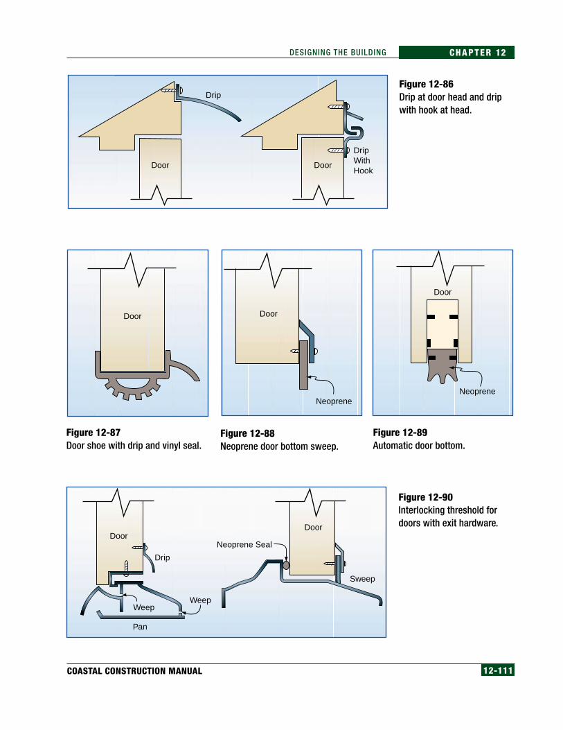
12-111COASTAL CONSTRUCTION MANUAL
CHAPTER 12DESIGNING THE BUILDING
Figure 12-87Door shoe with drip and vinyl seal.
Door Door
Neoprene
Door
Neoprene
Figure 12-88Neoprene door bottom sweep.
Figure 12-89Automatic door bottom.
Figure 12-90Interlocking threshold fordoors with exit hardware.
Figure 12-86Drip at door head and dripwith hook at head.
DoorDoor
Neoprene Seal
Sweep
WeepWeep
Drip
Pan
Drip
Door Door
DripWith Hook

12-112 FEDERAL EMERGENCY MANAGEMENT AGENCY
CHAPTER 12 DESIGNING THE BUILDING
12.7.3.2 WildfiresFor buildings in areas prone to wildfires, fire-rated metal doors and frames arerecommended. Door/frame assemblies are available in 3/4-, 1-1/2-, and 3-hour ratings.
Although construction of the door and frame are usually the same for thesethree ratings, the amount of allowable glass opening is decreased as thehourly rating is increased. Maximum protection is provided by a 3-hour ratedassembly with no glazing. When glazed openings are desired, maximumprotection is provided by fire-rated glass ceramic (this type of glass isdiscussed in Section 12.7.4.7).
For glass sliding doors, protection of the opening with fire-rated glass ceramicor a metal shutter is recommended; however, because a sliding glass door/shutter assembly has not been subjected to fire testing, its reliability isunknown. See Section 12.7.4 for shutter information.
12.7.4 Windows, Shutters, and SkylightsHigh winds and wildfires are the natural hazards that present the greatestthreat to windows and skylights. Strong seismic events can also damagewindows, but, in residential construction, this is not common. Hail can bevery damaging to skylights and occasionally causes window breakage.Although this section focuses on windows, shutters, and skylights, it alsoaddresses door glazing.
Figure 12-91Adjustable jamb/headweatherstripping.
Door Adjustable JambWeatherstrip

12-113COASTAL CONSTRUCTION MANUAL
CHAPTER 12DESIGNING THE BUILDING
Figure 12-92Hurricane Georges (1998),Puerto Rico. Inadequatewindow frame attachmentcaused the window frame tobe pulled out of the wall.
12.7.4.1 High WindsWindow and skylight assemblies (i.e., glazing, hardware for operable units,frame, and frame attachment to the wall/curb) must be of sufficient strengthto resist positive and negative design wind pressures. The assembly shouldbe specified to comply with wind load testing in accordance with ASTM E1233. (Note: ASTM E 330 is the most commonly used method forevaluating window assemblies; however, because E 1233 is a cyclic testmethod and E 330 is a static test, E 1233 is the preferred test method,particularly in hurricane-prone areas). Designers must specify the frameattachment to the wall, either by performance or prescriptive criteria, asinadequate frame attachment due to lack of design direction is a commonproblem as illustrated by Figure 12-92.
12.7.4.2 Windborne MissilesA special consideration of glazing is its susceptibility to breakage bywindborne missiles (debris). When a missile penetrates most materials, only asmall opening is made; when a missile penetrates most glazing materials,however, it can result in a very large opening. The opening is oftensufficiently large to increase the building’s internal pressure, which mayoverstress other building envelope components or the structure itself.Increased internal pressure can also damage interior partitions and ceilings. Asubstantial amount of wind-driven water may also enter through the breachedopenings. In windstorms other than hurricanes, the probability of a windowor skylight being struck by a missile is extremely low; however, in hurricane-prone regions, the missile load issue is of concern. Figure 12-93 shows a largewindow broken by windborne debris.

12-114 FEDERAL EMERGENCY MANAGEMENT AGENCY
CHAPTER 12 DESIGNING THE BUILDING
Missile impact criteria are included in the IBC 2000 and IRC2000. ASCE 7-98, the IBC, and the IRC require that one of the following conditions be metfor glazing (including skylights) in windborne debris regions:
1. The glazing must either be designed to resist missiles or be protected byshutters, or
2. The building in which the glazing is used must be designed as apartially enclosed building.
According to ASCE 7-98, the IBC, and the IRC, windborne debris regions areareas within hurricane-prone regions located:
• within 1 mile of the coast where the basic wind speed is equal to orgreater than 110 mph (3-sec peak gust) and in Hawaii, or
• in all areas where the basic wind speed is equal to or greater than 120mph (3-sec peak gust), including Guam, Puerto Rico, the U.S. VirginIslands, or American Samoa.
It is recommended that in addition to being tested for air pressure (i.e., ASTME 1233 and E 330), glazed assemblies in windborne debris regions havesufficient strength to resist missile loads specified in the IBC and IRC and betested in accordance with ASTM E 1886-97 and E 1996-99. (Note: A specialimpact-resistant glazing assembly or shutters will be necessary.) Glazingprotected with shutters should also be designed to resist the positive andnegative design wind pressure.
Figure 12-93Hurricane Georges (1998),Puerto Rico. Window brokenby windborne debris.
NOTEBecause of the extensive inte-rior damage that can be causedby wind and rainwater if glazingis breached, and because of thelarge internal pressure createdby a breach of the building en-velope, this manual recom-mends the use of shutters orimpact-resistant glass ratherthan the design of partially en-closed buildings.

12-115COASTAL CONSTRUCTION MANUAL
CHAPTER 12DESIGNING THE BUILDING
The typical missile test criteria include the following provisions:
• Small missiles weighing 2 grams shall impact the surface at a speed of80 ft/sec (54 mph).
• Each test specimen shall receive 30 small missile impacts; these 30impacts are to be distributed over the surface of the window/door unit.
• Large missiles shall be wood 2x4s weighing 9 lb and impacting thesurface at a speed of 50 ft/sec (34 mph).
• Each test specimen shall receive two large-missile impacts, one in thecenter of the assembly, and one near the corner.
In addition to the missile impact standards, each of the window/doorassemblies must pass a cyclic pressure test. The assembly must first pass themissile impact test, then that same assembly is used in the cyclic pressure test.A pressure loading sequence for both inward- and outward-acting pressure, arange of pressure, the number of cycles, and the duration of each cycle isgiven. Tests should also be conducted for shutters, skylights, and glazingprotective film.
12.7.4.3 DurabilityTo avoid corrosion problems, aluminum, wood or vinyl frames are recommendedfor buildings located within 3,000 feet of an ocean shoreline. Stainless steelframe anchors and hardware are also recommended in these areas. In areas withsevere termite problems, wood frames should either be treated or not used.
12.7.4.4 Water InfiltrationHurricanes and other coastal storms present enormous wind-driven rainwaterinfiltration problems. Leakage can occur at the glazing/frame interface, at theframe itself, or between the frame and wall. Because of the high design windpressures and numerous opportunities for leakage path development, someleakage should be anticipated when design wind speed conditions areapproached. A design approach to deal with this problem is to not run carpetall of the way to walls that have a large amount of glazing. Instead, a strip ofwater-resistant material such as tile could be specified along the wall. Duringa storm, towels could be placed along the strip to absorb water infiltration.These actions can help protect carpets from water damage.
It is recommended that window units be tested in accordance with ASTM D1233 for water infiltration. The challenge with prefabricated window units ismeeting the need for successful integration between the window units and thewalls. To the extent possible, detailing of the interface between the wall andwindow units should rely on sealants as the secondary line of defense againstwater intrusion, rather than making them the primary protection.

12-116 FEDERAL EMERGENCY MANAGEMENT AGENCY
CHAPTER 12 DESIGNING THE BUILDING
The design of joints between walls and window units should consider theshape of the sealant joint (i.e., a square joint is typically preferred) and typeof sealant to be specified. The sealant joint should be detailed so that thesealant is able to bond on only two opposing surfaces (i.e., a backer rod orbond-breaker tape should be specified). Butyl is recommended forconcealed sealants, and polyurethane is recommended for exposed sealants.During installation, cleanliness of the sealant substrate is important(particularly if polyurethane or silicone sealants are specified), as well astooling of the sealant.
A removable stop, as illustrated in Figure 12-94, protects the sealant fromdirect exposure to the weather, and the protection can reduce the wind-drivenrain demand on the sealant.
On-site water infiltration testing in accordance with ASTM E 1105 can bespecified in instances where water infiltration is particularly important;however, this is an expensive test.
12.7.4.5 ShuttersIf shutters are used to provide missile protection, they should be tested asdiscussed above for glazing (see Section 12.7.4.2). Miami-Dade County,Florida, has established a product approval mechanism for shutters to ensurethat these important protective devices and the method used for securing themto the building are rated for particular wind and missile loads. A variety ofshutter designs and materials are available. For windows that are difficult toreach, motor-driven rollup shutters are available as illustrated in Figure 12-95.Shutter designs that use permanently installed tracks facilitate rapidattachment of shutter panels as illustrated in Figure 12-96.
Figure 12-94Protection of sealantwith a stop.
Removable Stop
Air Space Behind Stop
Glazing
Wall
Window Frame
Sealant
Backer Rod
NOTEMissile impact standards(ASTM E 1886 and E 1996)cover criteria for small andlarge missiles. Shutters can becostly, so the designer or ownermay want to evaluate debrisand impact potential vs. thecost of shutters for the designwind event. The most importantenvelope protection goal is toprevent an opening from allow-ing internal pressure increasesin the building and to preventwindblown water from causinginterior damage.
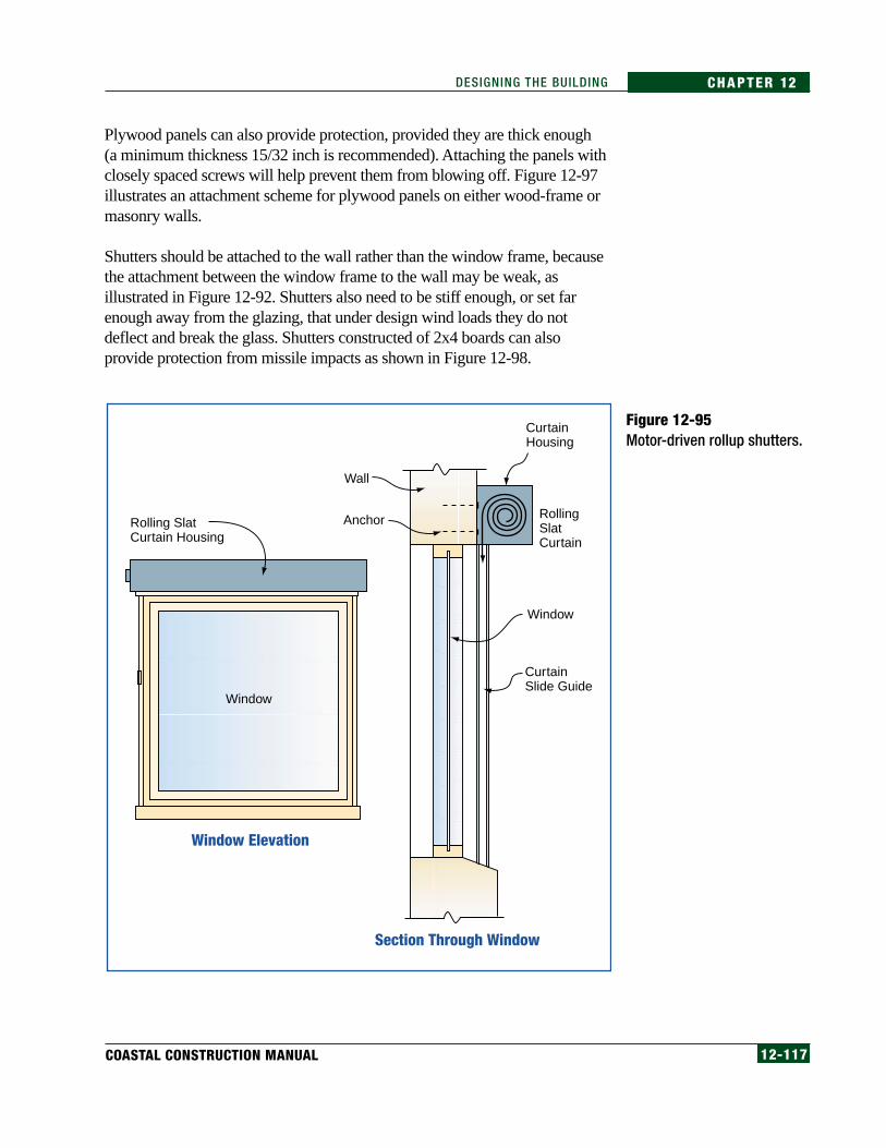
12-117COASTAL CONSTRUCTION MANUAL
CHAPTER 12DESIGNING THE BUILDING
Plywood panels can also provide protection, provided they are thick enough(a minimum thickness 15/32 inch is recommended). Attaching the panels withclosely spaced screws will help prevent them from blowing off. Figure 12-97illustrates an attachment scheme for plywood panels on either wood-frame ormasonry walls.
Shutters should be attached to the wall rather than the window frame, becausethe attachment between the window frame to the wall may be weak, asillustrated in Figure 12-92. Shutters also need to be stiff enough, or set farenough away from the glazing, that under design wind loads they do notdeflect and break the glass. Shutters constructed of 2x4 boards can alsoprovide protection from missile impacts as shown in Figure 12-98.
Figure 12-95Motor-driven rollup shutters.
Rolling SlatCurtain Housing
Curtain Housing
Rolling Slat Curtain
Curtain Slide Guide
Section Through Window
Window Elevation
Window
Wall
Window
Anchor

12-118 FEDERAL EMERGENCY MANAGEMENT AGENCY
CHAPTER 12 DESIGNING THE BUILDING
Figure 12-96Hurricane Georges (1998),Puerto Rico. Permanentlyinstalled shutter tracks.
Figure 12-97Plywood “shutter”attachment on either wood-frame or masonry walls.
Continuous2"x4" Trim forSpacing
Permanent Anchor Installed in Masonry
5/8" ExpansionBolt at 24" o.c.Minimum
Lag Screwat 18" o.c.Minimum
15/32" PlywoodMinimum
15/32" PlywoodMinimum
Caulk
Horizontal andVertical 2"x4"Stiffeners
Horizontaland Vertical2"x4"Stiffeners
Continuous2"x4" Trimfor Spacing
6"Minimum
WindowGlass
WindowSill
WindowSill
WindowGlass
Wood Stud Wall Masonry Wall
6"Minimum
NOTEThe Engineered WoodAssociation (formerly theAmerican Plywood Association)has prepared five brochures thatpresent hurricane shutterdesigns for wood-frame andmasonry buildings. Thebrochures are available on-lineat the Engineered WoodAssociation website at http://www.apawood.org/

12-119COASTAL CONSTRUCTION MANUAL
CHAPTER 12DESIGNING THE BUILDING
12.7.4.6 SeismicGlass breakage due to in-plane wall deflection is unlikely; however, specialconsideration should be given to walls that have a high percentage ofwindows and limited shear capacity. In these cases, it is important to analyzethe in-plane wall deflection to verify that it will not exceed the limitsprescribed in the building code.
12.7.4.7 WildfiresLimited data and guidelines are available related to performance of glazingsubjected to wildfires. Reports from California (McMullen 1994) indicatethat insulated (i.e., double-pane) windows were found to be an effectiveinsulator against radiant heat exposure. Fire-rated glass ceramic is also a veryheat-resistant material, but it is relatively expensive. Insulated windows couldbe composed of a fire-rated glass ceramic for the outer lite and annealed glassfor the inner lite. With these approaches, metal frames should provide greaterreliability than wood or vinyl frames.
Another approach is to protect the window openings with metal shutterssimilar to those shown in Figures 12-95 and 12-96; however, because thesetypes of shutter assemblies have not been subjected to fire testing, theirreliability is unknown.
12.7.4.8 HailA test method has not been developed specifically for testing skylights forhail-resistance. However, ASTM E 822, for testing hail-resistance of solarcollectors, could be used for assessing the hail-resistance of skylights.
Figure 12-98Hurricane Marilyn (1995),U.S. Virgin Islands.Shutters constructed of 2x4lumber.

12-120 FEDERAL EMERGENCY MANAGEMENT AGENCY
CHAPTER 12 DESIGNING THE BUILDING
12.7.5 Roof CoveringsHigh-winds, seismic events, wildfires, and hailstorms are the natural hazardsthat can cause the greatest damage to roof covering systems. In addition todamage that can be inflicted on the roof covering itself, there are secondaryissues that are of greater importance. When high winds damage the roofcovering, water infiltration commonly causes significant damage to theinterior of the building and its contents. Water infiltration may also occur aftervery large hail impact. During seismic events, heavy roof coverings such astiles or slate may be dislodged and fall from the roof and present a hazard ifthe building is occupied during the event. A roof covering system that is nothighly resistant to fire exposure can result in the destruction of the buildingduring a wildfire.
Residential buildings typically have steep-slope roofs (i.e., a slope greater than3:12). Some residential buildings have low-slope roofs, which can be roofedwith a variety of systems. Low-slope roof systems are discussed in Section12.7.5.8.
A variety of products can be used for steep-slope coverings. The followingcommonly used products are discussed below: asphalt composition shingles,cement-fiber shingles, liquid-applied membranes, tiles, metal panels, metalshingles, slate, and wood shingles and shakes. All of these steep-slope roofingcoverings are air-permeable, except for the liquid-applied membrane andmetal panel systems, which are air-impermeable. The wind loads derived inChapter 11 represent the pressure differential between the exterior and interiorsurfaces of the roof system. For air-impermeable coverings, the roof coveringshould typically be designed to resist the full wind load; however, because ofpartial air-pressure equalization provided by air-permeable coverings, thewind loads derived in Chapter 11 can overestimate the load on air-permeablecoverings. ASCE 7 allows the designer to use the full design load or calculatethe load by using a pressure coefficient that was specifically developed for theair-permeable element being considered. Research on special pressurecoefficients have been developed only for asphalt shingles and tiles.Therefore, according to ASCE 7, the other air-permeable roofing productshave to be designed for the full wind load, which is problematic for several ofthe coverings as discussed below.
12.7.5.1 Asphalt ShinglesThe discussion of asphalt shingles relates only to shingles with self-sealtabs. Mechanically interlocked shingles are not addressed because of theirlimited use.
NOTEThe IBC and IRC include require-ments for roof coverings in high-wind areas.
NOTERoofing failures in high-windareas are one of the most com-mon causes of substantial build-ing damage and dollar loss.
NOTEWhen retrofitting in high-windareas, it is recommended thatthe existing roof covering be re-moved so that the roof deck canbe checked for deteriorationand to verify that it is ad-equately attached.

12-121COASTAL CONSTRUCTION MANUAL
CHAPTER 12DESIGNING THE BUILDING
High Winds
A method for calculating uplift loads on asphalt shingles has been developed(Peterka et al. 1997). A pressure coefficient for use in the calculation hasalso been developed; however, that coefficient may not be applicable to allasphalt shingles. Additional research needs to be undertaken to determinecoefficients on all asphalt shingles. Until work on the uplift coefficients iscomplete, it is not possible to analyze loads on asphalt shingles. Therefore, aprescriptive solution based on results of field investigations and judgement isnecessary. However, with this approach, the uplift resistance provided by thesystem is unknown.
The key elements to successful wind performance include the bond-strengthof the self-seal strip, the mechanical properties of the shingle, and correctapplication of the shingle fasteners. If the tab lifts, the number of fastenersused to attach the shingle may influence whether or not shingles are blown off.Bond strength can be assessed by ASTM D 6381.
Underlayment
In the event of shingle blowoff, subsequent water infiltration damage can beavoided if the underlayment remains attached and is adequately sealed atpenetrations. However, to achieve reliable secondary protection, an enhancedunderlayment design is needed. The design enhancements include increasedblowoff resistance of the underlayment itself, increased resistance to waterinfiltration (primarily at penetrations), and increased resistance to extendedweather exposure.
If shingles are blown off, in some cases the underlayment is exposed for onlya week or two before a new roof covering is installed. But many roofsdamaged by hurricanes go unrepaired for several weeks. If a hurricane strikesa heavily populated area, roof covering damage is typically extensive.Therefore, because of the great work load, large numbers of roofs gounrepaired for several months. It is not uncommon for some roofs to gounrepaired for nearly a year.
The longer an underlayment will be exposed to weather, the more durable itwill need to be to provide adequate water infiltration protection for theresidence. The three options presented on page 12-122 are listed in order ofdecreasing resistance to long-term weather exposure. Option 1 provides thegreatest reliability for long-term exposure—it is advocated in areas that areheavily populated and where the design wind speed is equal to or greater than120 mph. Option 3 provides limited protection and is advocated only in areasthat have a modest population density and the design wind speed is less thanor equal to 110 mph (3-sec peak gust).
WARNINGASTM D 3161 and UnderwritersLaboratories (UL) 997 are virtu-ally identical test methods fordetermining uplift resistance ofasphalt shingles. However, com-plying with these methods doesnot ensure successful perfor-mance of shingles during high-wind events.
WARNINGIf the roof has a ridge vent thatis blown off, the underlaymentrecommendations do not pro-vide water infiltration protectionat ridge vent slots. To avoid leak-age at ridge vent slots, gable endvents and/or well-anchoredstack vents in lieu of ridge ventsshould be considered.

12-122 FEDERAL EMERGENCY MANAGEMENT AGENCY
CHAPTER 12 DESIGNING THE BUILDING
Option 1. Specify taping the joints of the plywood sheathing withroof tape (i.e., self-adhering modified bitumen). Specify that the tapebe a minimum of 4 inches wide, applied to a broom-clean deck, androlled with a roller. Seal around deck penetrations with roof tape,sealant, or asphalt roof cement. Apply a single layer of ASTM D 226Type II (#30) underlayment felt, attached with low-profile capped-head nails or thin metal disks (“tin caps”) attached with roofing nails.Fasten at approximately 6 inches on center (o.c.) along the laps and atapproximately 12 inches o.c. along two rows in the field of the sheetbetween the side laps. Apply a single layer of self-adhering modifiedbitumen complying with ASTM D 1970. Seal the modified bitumensheet to the deck penetrations with roof tape or asphalt roof cement.
Note: (1) Because of its enhanced resistance to weather exposure,plywood is recommended in lieu of OSB, in the event theunderlayment is blown off. (2) The purpose of the tape over theplywood joints is to provide secondary protection if the underlaymentis blown off. (3) As an alternate to the modified bitumen sheet, installtwo plies of felt complying with ASTM D 2178 Type IV. Set eachsheet in a continuous mopping of hot asphalt complying with ASTMD 312 Type IV.
Option 2. Specify taping the sheathing joints and sealing aroundpenetrations as described in Option 1. Specify two plies ofunderlayment felt with offset side laps, complying with ASTM D 226Type I (#15). Attach the underlayment with low-profile capped-headnails or thin metal disks (“tin caps”) attached with roofing nails.Fasten at approximately 6 inches o.c. along the laps and atapproximately 12 inches o.c. along a row in the field of the sheetbetween the side laps.
Note: If the building is within 3,000 feet of salt water, stainless steelor hot-dip galvanized fasteners are recommended for theunderlayment attachment.
Option 3. Specify taping the sheathing joints and sealing aroundpenetrations as described in Option 1. Apply a single layer of ASTMD 226 Type I (#15) underlayment felt in the normal fashion.
Note: (1) If the roof slope is less than 4:12, tape and seal thesheathing and follow the recommendations given in The NRCARoofing and Waterproofing Manual (NRCA 1996). (2) With thisoption, the underlayment has limited blowoff resistance. Waterinfiltration resistance is provided by the taped and sealed sheathingpanels. This option is intended where temporary or permanent repairsare likely to be made within several days after the roof covering isblown off.

12-123COASTAL CONSTRUCTION MANUAL
CHAPTER 12DESIGNING THE BUILDING
Shingle Products
If fiberglass-reinforced shingles are desired, specify shingles that comply withASTM D 3462. If organic-reinforced shingles are desired, specify shinglesthat comply with ASTM D 225. SBS modified bitumen shingles are anotheroption to consider. Because of the flexibility imparted by the SBS polymers,if a tab on a modified bitumen shingle lifts, it is less likely to break andblowoff. Compared to fiberglass-reinforced shingles, organic-reinforcedshingles typically have substantially lower resistance to pulling over fastenerheads. ASTM D 3462 specifies a minimum fastener pull-through resistanceof 20 lb/ft at 70° F; however, fiberglass-reinforced shingles are available witha fastener pull-through resistance in excess of 30 lb/ft. In high-wind (less thanor equal to 90 mph 3-sec peak gust) areas, it is recommended that a minimumpull-through resistance of 25 lb/ft be specified. In areas with extremely highdesign wind speeds (greater than 120 mph 3-sec peak gust), it isrecommended that a minimum value of 30 lb/ft be specified.
At the time this manual was produced, data on bond-strength of the self-sealadhesive were typically unavailable. Bond strengths range fromapproximately 3 to 20 lb/ft at 70° F. It is recommended that bond-strengthdata be sought from manufacturers and that products be specified with aminimum of 12 lb/ft in high-wind areas. In areas with extremely high designwind speeds, it is recommended that a minimum value of 17 lb/ft be specified.
Attaching and Sealing
Specify attachment with six nails (rather than staples) per shingle. Locate thenails as indicated in The NRCA Steep Roofing Manual. For roofs within 3,000feet of the ocean, hot-dip galvanized (rather than electroplated [EG]) orstainless steel nails are recommended.
It is recommended that the designer specify that the starter strip be nailedapproximately 1–2-1/2 inches from the eave edge of the starter strip. Oneinch is preferred, but framing conditions may require that the nails be placedfurther away. The fasteners should be placed in sheathing or framing lumber,rather than in trim boards. Six nails per starter strip are recommended.Specify that the starter strip and first course overhang the eave metal byapproximately 1/4 inch. The 1/4-inch overhang will provide a drip edgewithout exposing much shingle beyond the eave for wind to lift. It isrecommended that the designer specify sealing the first course of shingles byplacing three (approximately 1-inch-diameter) dabs of asphalt roof cementover the starter strip so that the overlying tab of the first course will beadhered. The eave detail is illustrated in Figure 12-99.
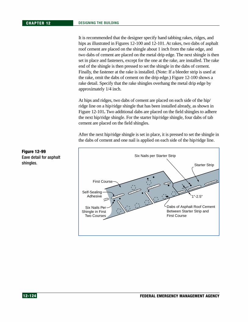
12-124 FEDERAL EMERGENCY MANAGEMENT AGENCY
CHAPTER 12 DESIGNING THE BUILDING
It is recommended that the designer specify hand tabbing rakes, ridges, andhips as illustrated in Figures 12-100 and 12-101. At rakes, two dabs of asphaltroof cement are placed on the shingle about 1 inch from the rake edge, andtwo dabs of cement are placed on the metal drip edge. The next shingle is thenset in place and fasteners, except for the one at the rake, are installed. The rakeend of the shingle is then pressed to set the shingle in the dabs of cement.Finally, the fastener at the rake is installed. (Note: If a bleeder strip is used atthe rake, omit the dabs of cement on the drip edge.) Figure 12-100 shows arake detail. Specify that the rake shingles overhang the metal drip edge byapproximately 1/4 inch.
At hips and ridges, two dabs of cement are placed on each side of the hip/ridge line on a hip/ridge shingle that has been installed already, as shown inFigure 12-101. Two additional dabs are placed on the field shingles to adherethe next hip/ridge shingle. For the starter hip/ridge shingle, four dabs of tabcement are placed on the field shingles.
After the next hip/ridge shingle is set in place, it is pressed to set the shingle inthe dabs of cement and one nail is applied on each side of the hip/ridge line.
Figure 12-99Eave detail for asphaltshingles.
Dabs of Asphalt Roof Cement Between Starter Strip and First Course
Six Nails per Starter Strip
1"-2.5"
Starter Strip
First Course
Self-SealingAdhesive
Six Nails PerShingle in First
Two Courses

12-125COASTAL CONSTRUCTION MANUAL
CHAPTER 12DESIGNING THE BUILDING
Hip and ridge shingles are normally cut from a strip shingle.Premanufactured hip/ridge shingles are also available and may or may nothave self-sealing adhesive. If they do not, specify application of cement toreplicate the adhesive on the strip shingles.
Because of extra thickness of materials at hips and ridges, longer nailsthan those used in the roof field are needed. All nails should penetratethe underside of the sheathing, or penetrate at least 3/4 inch into woodplank decks.
Some building codes require that hips, ridges, rakes, eaves, and valleys be setin wide continuous bands of asphalt roof cement; however, this practice mayresult in shingle blistering, which could shorten shingle life and be
Figure 12-100Rake detail for asphaltshingles.
Figure 12-101Hip and ridge detail forasphalt and compositionshingles.
UnderlaymentDrip Edge
Self-Sealing Adhesive
Tab
Nails
Nails
Tab Cement
Tab Cement
Fastener
Self-Sealing Adhesive
Fastener FromOverlying Shingle

12-126 FEDERAL EMERGENCY MANAGEMENT AGENCY
CHAPTER 12 DESIGNING THE BUILDING
aesthetically objectionable to the homeowner. If the code requires widecontinuous bands of cement, it is recommended that the designer request thebuilding official to allow the use of dabs of cement as recommended above.
Ridge Vents
Ridge vents should be evaluated for susceptibility to penetration by wind-driven rain. Test methods or specific design guidance have not beendeveloped. See Section 12.7.6 for additional information.
Wildfires
Organic-reinforced shingle systems achieve only a Class C fire-resistancerating, which indicates very little fire resistance. Fiberglass-reinforced shinglesystems achieve a Class A fire-resistance rating, which is the highest ratingachieved through ASTM E 108 fire testing. Under typical fire exposureconditions, fiberglass-reinforced shingle systems normally provide sufficientfire resistance; however, they typically do not provide sufficient resistance tothe extreme conditions induced by wildfires. Where enhanced resistance towildfires is desired, another type of roof covering is recommended.
Hail
UL 2218 is a test method for assessing simulated hail resistance of roofingsystems. This test yields four ratings (Classes 1–4). Systems rated Class 4have the greatest impact resistance. Asphalt shingles are available in all fourclasses. It is recommended that asphalt shingle systems on buildings locatedin areas vulnerable to hail be specified to pass UL 2218, at a Class levelcommensurate with the hail load. Hail resistance of asphalt shingles dependspartly on the condition of the shingles at the time they are impacted and islikely to decline with roof age.
12.7.5.2 Cement-Fiber ShinglesCement-fiber shingles are made to simulate the appearance of slate, tile,wood shingles, or wood shakes. The material properties of various cement-fiber products vary due to differences in material composition andmanufacturing processes.
High Winds
Because of limited market share of cement-fiber shingles in areas whereresearch has been conducted after high-wind events, few data are availableon their wind performance. At the time this manual was produced,manufacturers had not conducted research to determine a suitable pressurecoefficient or coefficients; therefore, demonstrating compliance withASCE 7 is problematic with these products until such a coefficient(s) is
12-127COASTAL CONSTRUCTION MANUAL
CHAPTER 12DESIGNING THE BUILDING
developed. A consensus test method for uplift resistance has not beendeveloped for these products.
In high-wind areas, mechanical attachment should be specified in corner andperimeter roof zones. With some of the lighter-weight products, mechanicalattachment in the field of the roof may also be prudent. In extremely high-wind areas, mechanical attachment in the field of the roof should be specified.Additional mechanical attachment near the tail of the shingle should also bespecified in perimeter and corner zones, and perhaps in the field of the roof.Because these prescriptive attachment suggestions are based on limitedinformation, the uplift resistance that they provide is unknown.
To minimize water damage in the event of blowoff of the cement-fiber covering,the underlayment recommendations for asphalt shingles are suggested. Forcement-fiber systems, however, a Type II (i.e., #30) felt is recommended inorder to provide more puncture resistance during application. Stainless steel orhot-dip galvanized fasteners are recommended for roofs within 3,000 feet ofthe ocean. Note that cement-fiber systems are vulnerable to breakage frommissile impact. See the discussion in Section 12.7.5.4.
Seismic
Cement-fiber products are relatively heavy and, unless they are adequatelyattached, they can be dislodged during strong seismic events and fall fromthe roof. At time this manual was produced, manufacturers had notconducted research or developed design guidance for use of these productsin areas prone to large ground motion accelerations. The guidance providedin the Section 12.7.5.4 is suggested until specific guidance is developed forcement-fiber products.
Wildfires
Most cement-fiber systems can achieve a Class A fire-resistance rating;however, some only achieve a Class B. The Class A systems should providerelatively good fire resistance during wildfires; however, because cement-fiberproducts typically have less thermal mass than tiles, they probably do notoffer as much protection as tiles. Cement-fiber products may not be as fire-resistant as metal-panel or metal-shingle systems.
Hail
At the time this manual was being produced, one cement-fiber assembly hadpassed UL 2218 with a Class 2 rating. It is recommended that cement-fibershingle systems on buildings in areas vulnerable to hail be specified to pass UL2218, at a class level commensurate with the hail load. If products with thedesired class are not available, another type of product should be considered.

12-128 FEDERAL EMERGENCY MANAGEMENT AGENCY
CHAPTER 12 DESIGNING THE BUILDING
12.7.5.3 Liquid-Applied MembranesLiquid-applied membranes are not common on the U.S. mainland, but they arecommon in Guam, the U.S. Virgin Islands, Puerto Rico, and American Samoa.
High Winds
Investigations following strong hurricanes and typhoons have revealed thatliquid-applied membranes installed over concrete and plywood decks haveoffered excellent performance (provided the deck remains attached to thebuilding). This type of roof covering has extremely high wind-resistancereliability.
It has been found that unprotected concrete roof decks could eventuallyexperience problems with corrosion of the slab reinforcement. It isrecommended that all concrete roof decks be covered with some type of roofcovering.
Wildfires
Liquid-applied membranes over concrete decks should provide excellentwildfire-resistance. A Class A rating can be achieved for liquid-appliedmembranes over a plywood deck; however, where enhanced resistance to theextreme conditions induced by wildfires is desired, a roof covering other thana liquid-applied membrane over plywood is recommended.
Hail
At the time this manual was being produced, no liquid-applied membranesover concrete or plywood decks had been evaluated by UL 2218.
12.7.5.4 TilesClay and extruded concrete tiles are available in a variety of profiles andattachment methods.
High Winds
Loads and Resistance
Methods to calculate uplift loads and load resistance on tiles have beendeveloped and incorporated into the IBC for loose-laid and mechanicallyattached tiles. Coefficients have not been determined for mortar-set or foam-set systems.
Storm damage investigations have revealed poor performance of wire-tiedsystems as illustrated in Figure 12-102.
NOTEFor additional information, seeSBCCI standard SSTD 11-97,Test Standard for DeterminingWind Resistance of Concrete orClay Roof Tiles (SBCCI 1997b)for additional information.
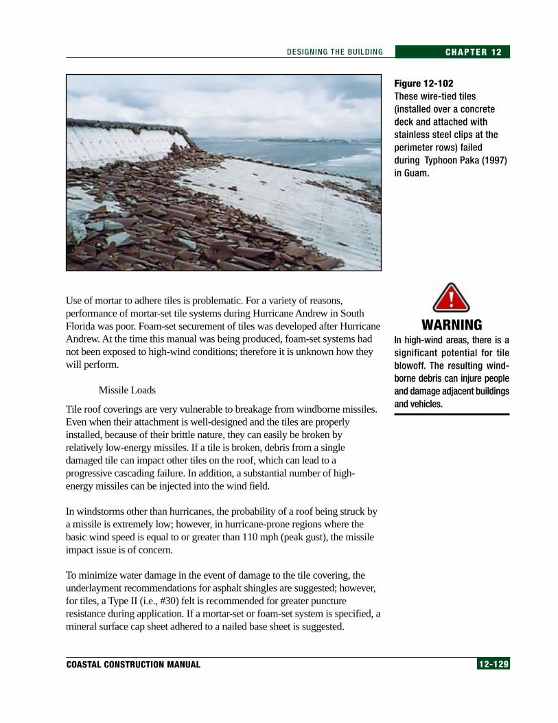
12-129COASTAL CONSTRUCTION MANUAL
CHAPTER 12DESIGNING THE BUILDING
Use of mortar to adhere tiles is problematic. For a variety of reasons,performance of mortar-set tile systems during Hurricane Andrew in SouthFlorida was poor. Foam-set securement of tiles was developed after HurricaneAndrew. At the time this manual was being produced, foam-set systems hadnot been exposed to high-wind conditions; therefore it is unknown how theywill perform.
Missile Loads
Tile roof coverings are very vulnerable to breakage from windborne missiles.Even when their attachment is well-designed and the tiles are properlyinstalled, because of their brittle nature, they can easily be broken byrelatively low-energy missiles. If a tile is broken, debris from a singledamaged tile can impact other tiles on the roof, which can lead to aprogressive cascading failure. In addition, a substantial number of high-energy missiles can be injected into the wind field.
In windstorms other than hurricanes, the probability of a roof being struck bya missile is extremely low; however, in hurricane-prone regions where thebasic wind speed is equal to or greater than 110 mph (peak gust), the missileimpact issue is of concern.
To minimize water damage in the event of damage to the tile covering, theunderlayment recommendations for asphalt shingles are suggested; however,for tiles, a Type II (i.e., #30) felt is recommended for greater punctureresistance during application. If a mortar-set or foam-set system is specified, amineral surface cap sheet adhered to a nailed base sheet is suggested.
WARNINGIn high-wind areas, there is asignificant potential for tileblowoff. The resulting wind-borne debris can injure peopleand damage adjacent buildingsand vehicles.
Figure 12-102These wire-tied tiles(installed over a concretedeck and attached withstainless steel clips at theperimeter rows) failedduring Typhoon Paka (1997)in Guam.
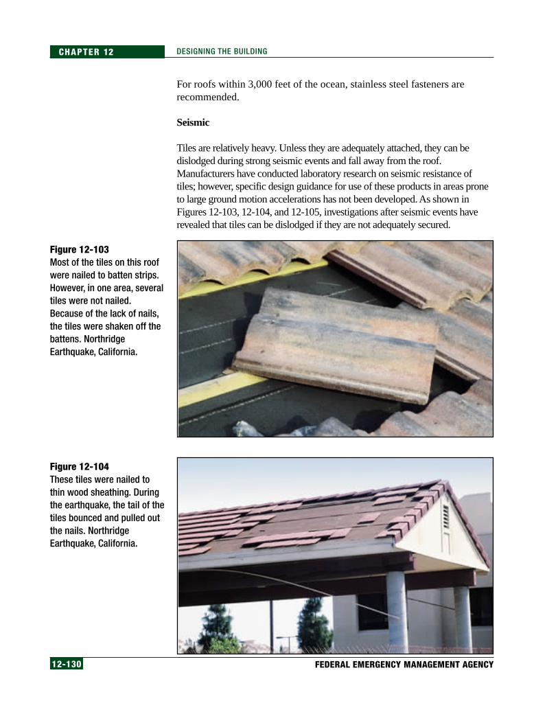
12-130 FEDERAL EMERGENCY MANAGEMENT AGENCY
CHAPTER 12 DESIGNING THE BUILDING
For roofs within 3,000 feet of the ocean, stainless steel fasteners arerecommended.
Seismic
Tiles are relatively heavy. Unless they are adequately attached, they can bedislodged during strong seismic events and fall away from the roof.Manufacturers have conducted laboratory research on seismic resistance oftiles; however, specific design guidance for use of these products in areas proneto large ground motion accelerations has not been developed. As shown inFigures 12-103, 12-104, and 12-105, investigations after seismic events haverevealed that tiles can be dislodged if they are not adequately secured.
Figure 12-103Most of the tiles on this roofwere nailed to batten strips.However, in one area, severaltiles were not nailed.Because of the lack of nails,the tiles were shaken off thebattens. NorthridgeEarthquake, California.
Figure 12-104These tiles were nailed tothin wood sheathing. Duringthe earthquake, the tail of thetiles bounced and pulled outthe nails. NorthridgeEarthquake, California.

12-131COASTAL CONSTRUCTION MANUAL
CHAPTER 12DESIGNING THE BUILDING
The following attachment guidance is recommended in seismic areas whereshort period acceleration exceeds 0.5g.
• When tiles are only loose-laid on battens, they can be shaken off asshown in Figure 12-103. If tiles are laid on battens, supplementalmechanical attachment is recommended.
• Tiles nailed only at the head may or may not perform well. If they areattached with a smooth-shank nail into a thin plywood or orientedstrand board (OSB) deck, pullout can occur (see Figure 12-104).Specifying ring-shank or screw-shank nails or screws is recommended;however, even with these types of fasteners, the tail of the tile canbounce, causing enlargement of the nail hole by repeated pounding. Toovercome this problem, specify wind clips near the tail of the tile.
• Tiles that are attached by only one fastener experience eccentricloading. This problem can be overcome by specifying wind clips nearthe tail of the tile.
• Two-piece barrel (i.e., mission) tiles attached with straw nails can slidedownslope a few inches because of deformation of the long straw nail.This problem can be overcome by specifying a wire-tied system orproprietary fasteners that are not susceptible to downslope deformation.
• When tiles are cut to fit near hips and valleys, the portion of the tilewith the nail hole(s) is often cut away (see Figure 12-105).Supplemental securement is necessary to avoid displacement of theseloose tiles.
• Securement of rake, hip, and ridge tiles with mortar is ineffective. Ifmortar is specified, it should be augmented with mechanical attachment.
Figure 12-105Northridge Earthquake,California. The tile in thecenter of this photographslipped out from underneaththe hip tiles. The tile thatslipped was trimmed to fit atthe hip. The trimmingeliminated the nail holes andno other attachment wasprovided. The friction fit wasinadequate to resist theseismic forces.

12-132 FEDERAL EMERGENCY MANAGEMENT AGENCY
CHAPTER 12 DESIGNING THE BUILDING
• Rake trim tiles fastened just near the head of the tile often slip over thefastener head because the nail hole is enlarged by repeated pounding.Additional restraint is needed for the trim pieces. Also, the design ofsome rake trim pieces makes them more inherently resistant todisplacement than other rake trim designs.
For roofs within 3,000 feet of the ocean, stainless steel fasteners arerecommended.
Wildfires
Tiles are noncombustible and have a relatively large thermal mass. Therefore, tileroof systems should provide excellent wildfire-resistance. Lightweight tileproducts are available, but it is recommended that normal-weight tiles bespecified in lieu of lightweight tiles when enhanced wildfire resistance is desired.
Hail
At the time this manual was being produced, no tile assembly had passed UL2218. Tile manufacturers assert that UL 2218 is not a good test method to assessnon-ductile products such as tiles. A proprietary alternative test method isavailable to assess non-ductile products; however, at the time this manual wasbeing produced, it had not been recognized as a consensus test method.
12.7.5.5 Metal Panels and Metal ShinglesA variety of metal panel and shingle systems are available. Some of theseproducts simulate the appearance of tiles or wood shakes.
High Winds
Because of the great differences in system designs, the wind performance ofmetal systems varies widely. For metal-panel systems, it is recommended thatuplift resistance be based on the ASTM E 1592 test method; for metal-shinglesystems, it is recommended that uplift resistance be based on ASTM E 330.Both of these systems should be considered as air-impermeable for thepurpose of calculating uplift loads.
For panel systems, it is recommended that two rows of fasteners be placedalong the eaves, hip, and ridges (see Figure 12-106). The first row should benear the edge/end of the panel (i.e., within 2–3 inches), and the next rowshould be approximately 3–4 inches from the first row. Hip and ridgeflashings should be attached with a double row of fasteners. For exposedfastener systems, the hip and ridge flashing fasteners can also serve as thepanel fasteners. For concealed clip systems, the hip and ridge fasteners are inaddition to the two clips along either side of the hip and ridge. Screws ratherthan nails should be used to attach clips, panels, and flashings.

12-133COASTAL CONSTRUCTION MANUAL
CHAPTER 12DESIGNING THE BUILDING
Stainless steel clips and fasteners are recommended. For enhanced corrosionprotection of steel panels/shingles, an aluminum zinc alloy (Galvalume®)coating is recommended in lieu of galvanizing. (Additional designinformation regarding corrugated metal roofing is provided in Appendix K.)
To minimize water damage in the event of damage to the metal covering, theunderlayment recommendations for asphalt shingles are suggested; however,for metal coverings, a Type II (i.e., #30) felt is recommended for greaterpuncture resistance during application.
Wildfires
Metal panel/shingle systems are noncombustible; however, they can readilytransmit heat to the substrate below. If metal roofing is installed over acombustible substrate such as wood, a thermal barrier is needed between thesubstrate and metal to achieve enhanced resistance to wildfires. The designshould be based on system testing.
Hail
Several metal panel and shingle systems have passed UL 2218. Althoughmetal systems have passed Class 4 (the Class with the greatest impactresistance), they often are severely dented by the testing. Although they maystill be effective in inhibiting water entry, they can be aestheticallyobjectionable. (Note: The appearance of the system is not included in the UL2218 evaluation criteria.)
Figure 12-106Hurricane Marilyn (1995),U.S. Virgin Islands. The ridgeflashing on this corrugatedmetal panel roof was wellattached, with a double rowof closely spaced fastenerson each side of the ridge.

12-134 FEDERAL EMERGENCY MANAGEMENT AGENCY
CHAPTER 12 DESIGNING THE BUILDING
12.7.5.6 SlateSome cement-fiber and tile products are marketed as “slate”; however, slate isa natural material. Cement-fiber and tile products that simulate slate areaddressed in Section 12.7.5.2.
High Winds
Because of limited usage of slate in areas where research has been conductedafter high-wind events, few data are available on its wind performance.Manufacturers have not conducted research to determine a suitable pressurecoefficient. Demonstrating slate’s compliance with ASCE 7 is problematicuntil such time as the coefficient is developed. A consensus test method foruplift resistance has not been developed for slate.
In extremely high-wind areas, mechanical attachment near the tail of the slateshould be specified in perimeter and corner zones, and perhaps in the field.Because this prescriptive attachment suggestion is based on limitedinformation, the uplift resistance that it provides is unknown.
To minimize water damage in the event of slate blowoff, the underlaymentrecommendations for asphalt shingles are recommended for slate as well;however, for slate systems, a Type II (i.e., #30) felt is recommended forgreater puncture resistance during application.
Seismic
Slate is relatively heavy. Unless adequately attached, it can be dislodgedduring strong seismic events and fall away from the roof. Manufacturers havenot conducted research or developed design guidance for use of slate in areasprone to large ground motion accelerations. The guidance provided for tiles,in Section 12.7.5.4, is suggested until specific guidance is developed for slate.
Wildfires
Slate is noncombustible and has a relatively large thermal mass. Therefore,slate roof systems should provide excellent wildfire-resistance.
Hail
At the time this manual was being produced, no slate assembly had passedUL 2218.

12-135COASTAL CONSTRUCTION MANUAL
CHAPTER 12DESIGNING THE BUILDING
12.7.5.7 Wood Shingles and ShakesHigh Winds
Research conducted after high-wind events has shown that wood shingles/shakes can perform very well during high winds if they are not deterioratedand if they have been attached in accordance with standard attachmentrecommendations.
At the time this manual was produced, manufacturers had not conductedresearch to determine a suitable pressure coefficient. Demonstratingcompliance with ASCE 7 is problematic with wood shingles/shakes until sucha coefficient is developed. At this time, a consensus test method for upliftresistance has not been developed for wood shingles/shakes.
For enhanced durability, preservative-treated wood is recommended for shingle/shake roofs on coastal buildings. For those roofs located within 3,000 feet of theocean, stainless steel nails (normally Grade 316) are recommended. See Figure12-107 for an example of shingle loss due to corrosion of the nail fasteners.
Figure 12-107Loss of wood shingles on thisNorth Carolina house duringHurricane Bertha (1996) wasdue to corrosion of fasteners.
Wildfires
Wood shingle and shake roofs (including those with fire-resistive treatment)are not recommended in areas prone to wildfires.
Hail
At the time this manual was being produced, no wood-shingle assembly hadpassed UL 2218; however, heavy shakes have passed Class 4 (the class withthe greatest impact resistance) and medium shakes have passed Class 3.
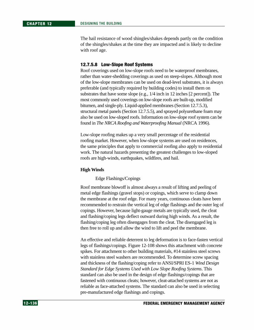
12-136 FEDERAL EMERGENCY MANAGEMENT AGENCY
CHAPTER 12 DESIGNING THE BUILDING
The hail resistance of wood shingles/shakes depends partly on the conditionof the shingles/shakes at the time they are impacted and is likely to declinewith roof age.
12.7.5.8 Low-Slope Roof SystemsRoof coverings used on low-slope roofs need to be waterproof membranes,rather than water-shedding coverings as used on steep-slopes. Although mostof the low-slope membranes can be used on dead-level substrates, it is alwayspreferable (and typically required by building codes) to install them onsubstrates that have some slope (e.g., 1/4 inch in 12 inches [2 percent]). Themost commonly used coverings on low-slope roofs are built-up, modifiedbitumen, and single-ply. Liquid-applied membranes (Section 12.7.5.3),structural metal panels (Section 12.7.5.5), and sprayed polyurethane foam mayalso be used on low-sloped roofs. Information on low-slope roof system can befound in The NRCA Roofing and Waterproofing Manual (NRCA 1996).
Low-slope roofing makes up a very small percentage of the residentialroofing market. However, when low-slope systems are used on residences,the same principles that apply to commercial roofing also apply to residentialwork. The natural hazards presenting the greatest challenges to low-slopedroofs are high-winds, earthquakes, wildfires, and hail.
High Winds
Edge Flashings/Copings
Roof membrane blowoff is almost always a result of lifting and peeling ofmetal edge flashings (gravel stops) or copings, which serve to clamp downthe membrane at the roof edge. For many years, continuous cleats have beenrecommended to restrain the vertical leg of edge flashings and the outer leg ofcopings. However, because light-gauge metals are typically used, the cleatand flashing/coping legs deflect outward during high winds. As a result, theflashing/coping leg often disengages from the cleat. The disengaged leg isthen free to roll up and allow the wind to lift and peel the membrane.
An effective and reliable deterrent to leg deformation is to face-fasten verticallegs of flashings/copings. Figure 12-108 shows this attachment with concretespikes. For attachment to other building materials, #14 stainless steel screwswith stainless steel washers are recommended. To determine screw spacingand thickness of the flashing/coping refer to ANSI/SPRI ES-1 Wind DesignStandard for Edge Systems Used with Low Slope Roofing Systems. Thisstandard can also be used in the design of edge flashings/copings that arefastened with continuous cleats; however, cleat-attached systems are not asreliable as face-attached systems. The standard can also be used in selectingpre-manufactured edge flashings and copings.
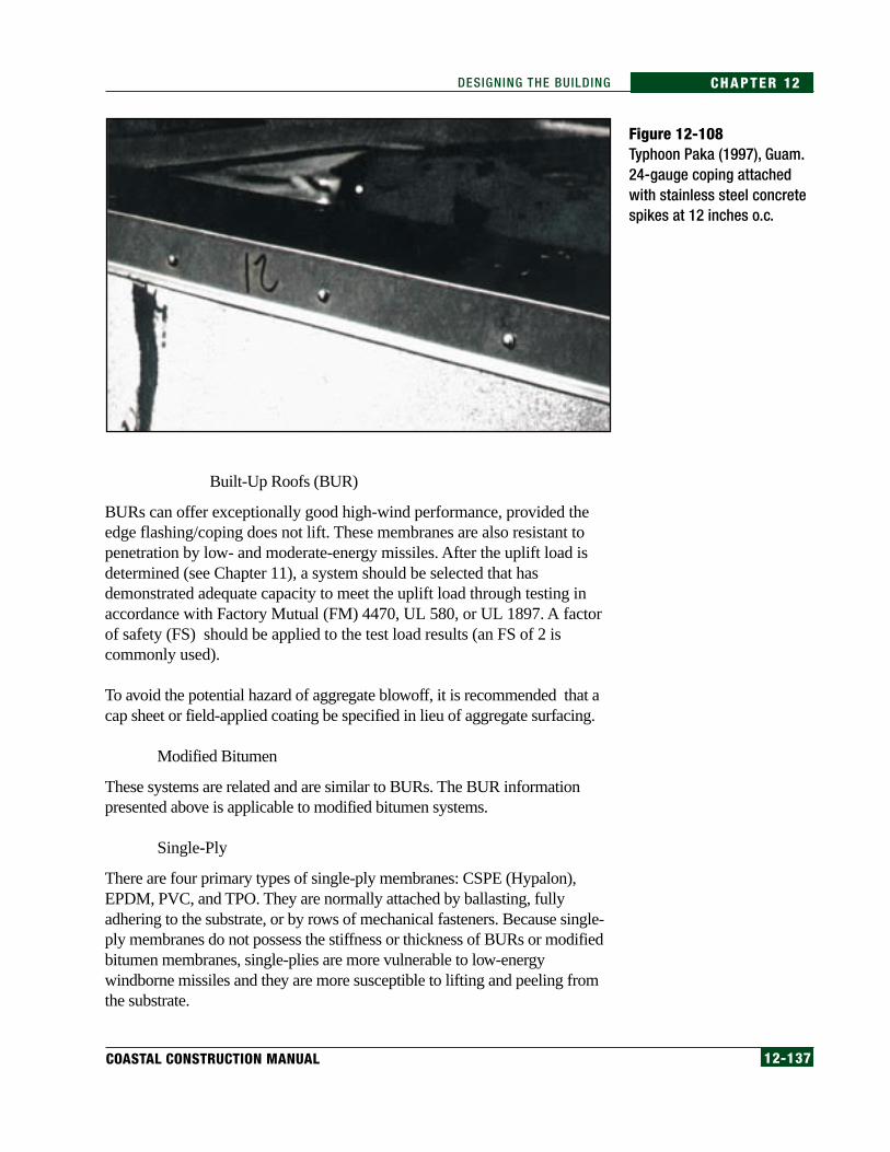
12-137COASTAL CONSTRUCTION MANUAL
CHAPTER 12DESIGNING THE BUILDING
Built-Up Roofs (BUR)
BURs can offer exceptionally good high-wind performance, provided theedge flashing/coping does not lift. These membranes are also resistant topenetration by low- and moderate-energy missiles. After the uplift load isdetermined (see Chapter 11), a system should be selected that hasdemonstrated adequate capacity to meet the uplift load through testing inaccordance with Factory Mutual (FM) 4470, UL 580, or UL 1897. A factorof safety (FS) should be applied to the test load results (an FS of 2 iscommonly used).
To avoid the potential hazard of aggregate blowoff, it is recommended that acap sheet or field-applied coating be specified in lieu of aggregate surfacing.
Modified Bitumen
These systems are related and are similar to BURs. The BUR informationpresented above is applicable to modified bitumen systems.
Single-Ply
There are four primary types of single-ply membranes: CSPE (Hypalon),EPDM, PVC, and TPO. They are normally attached by ballasting, fullyadhering to the substrate, or by rows of mechanical fasteners. Because single-ply membranes do not possess the stiffness or thickness of BURs or modifiedbitumen membranes, single-plies are more vulnerable to low-energywindborne missiles and they are more susceptible to lifting and peeling fromthe substrate.
Figure 12-108Typhoon Paka (1997), Guam.24-gauge coping attachedwith stainless steel concretespikes at 12 inches o.c.
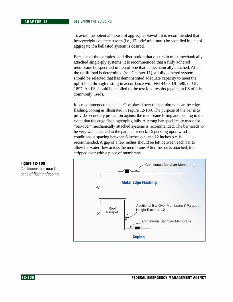
12-138 FEDERAL EMERGENCY MANAGEMENT AGENCY
CHAPTER 12 DESIGNING THE BUILDING
To avoid the potential hazard of aggregate blowoff, it is recommended thatheavyweight concrete pavers (i.e., 17 lb/ft2 minimum) be specified in lieu ofaggregate if a ballasted system is desired.
Because of the complex load distribution that occurs in most mechanicallyattached single-ply systems, it is recommended that a fully adheredmembrane be specified in lieu of one that is mechanically attached. Afterthe uplift load is determined (see Chapter 11), a fully adhered systemshould be selected that has demonstrated adequate capacity to meet theuplift load through testing in accordance with FM 4470, UL 580, or UL1897. An FS should be applied to the test load results (again, an FS of 2 iscommonly used).
It is recommended that a “bar” be placed over the membrane near the edgeflashing/coping as illustrated in Figure 12-109. The purpose of the bar is toprovide secondary protection against the membrane lifting and peeling in theevent that the edge flashing/coping fails. A strong bar specifically made for“bar-over” mechanically attached systems is recommended. The bar needs tobe very well attached to the parapet or deck. Depending upon windconditions, a spacing between 6 inches o.c. and 12 inches o.c. isrecommended. A gap of a few inches should be left between each bar toallow for water flow across the membrane. After the bar is attached, it isstripped over with a piece of membrane.
Figure 12-109Continuous bar near theedge of flashing/coping.
Continuous Bar Over Membrane
Continuous Bar Over Membrane
Additional Bar Over Membrane if ParapetHeight Exceeds 12"
Metal Edge Flashing
Coping
RoofParapet
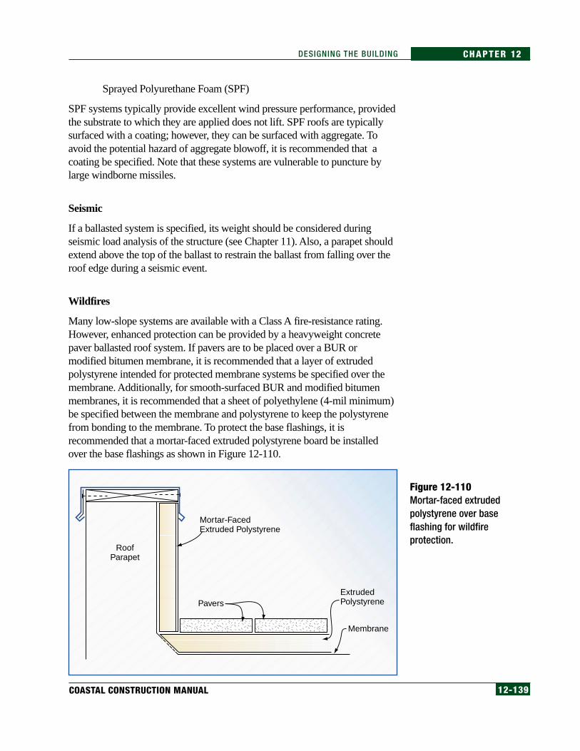
12-139COASTAL CONSTRUCTION MANUAL
CHAPTER 12DESIGNING THE BUILDING
Sprayed Polyurethane Foam (SPF)
SPF systems typically provide excellent wind pressure performance, providedthe substrate to which they are applied does not lift. SPF roofs are typicallysurfaced with a coating; however, they can be surfaced with aggregate. Toavoid the potential hazard of aggregate blowoff, it is recommended that acoating be specified. Note that these systems are vulnerable to puncture bylarge windborne missiles.
Seismic
If a ballasted system is specified, its weight should be considered duringseismic load analysis of the structure (see Chapter 11). Also, a parapet shouldextend above the top of the ballast to restrain the ballast from falling over theroof edge during a seismic event.
Wildfires
Many low-slope systems are available with a Class A fire-resistance rating.However, enhanced protection can be provided by a heavyweight concretepaver ballasted roof system. If pavers are to be placed over a BUR ormodified bitumen membrane, it is recommended that a layer of extrudedpolystyrene intended for protected membrane systems be specified over themembrane. Additionally, for smooth-surfaced BUR and modified bitumenmembranes, it is recommended that a sheet of polyethylene (4-mil minimum)be specified between the membrane and polystyrene to keep the polystyrenefrom bonding to the membrane. To protect the base flashings, it isrecommended that a mortar-faced extruded polystyrene board be installedover the base flashings as shown in Figure 12-110.
Figure 12-110Mortar-faced extrudedpolystyrene over baseflashing for wildfireprotection.
Pavers
Mortar-FacedExtruded Polystyrene
ExtrudedPolystyrene
Membrane
RoofParapet

12-140 FEDERAL EMERGENCY MANAGEMENT AGENCY
CHAPTER 12 DESIGNING THE BUILDING
Hail
It is recommended that a system that has passed the Factory Mutual ResearchCorporation’s severe hail test be specified. Enhanced hail protection can beprovided by a heavyweight concrete-paver-ballasted roof system, as discussedin the section above.
If the pavers are installed over a single-ply membrane, it is recommended thata layer of extruded polystyrene intended for protected membrane systems bespecified over the membrane to provide protection in the event the paversbreak. Alternatively, a stone protection mat intended for use with aggregate-ballasted systems could be specified.
12.7.6 Roof Ridge VentsContinuous ridge vent installations, primarily used on roofs with asphaltshingles, have typically not addressed the issue of maintaining structuralintegrity of the roof sheathing. When the roof sheathing is used as a structuraldiaphragm as it is in high-wind and seismic hazard areas, the structuralintegrity of the roof can be compromised by the continuous vent.
The roof sheathing, usually plywood or oriented strand board (OSB), isintended to act as a diaphragm. The purpose of the diaphragm is to resistlateral forces. To properly function, the diaphragm must have the capability oftransferring the load at its boundaries from one side of the roof to the other; itnormally does this through the ridge board. The continuity, or load transfer isaccomplished with nails. This approach is illustrated by Figure 12-111.
Figure 12-111Method for maintaining acontinuous load path atthe roof ridge by nailingroof sheathing.
Nails From Sheathing to Ridge Board
RoofSheathing
NOTE: If roof sheathing is cutand removed to achieve anair slot, continuity and diaphragm action are affected.
Ridge Board
Joist or Truss
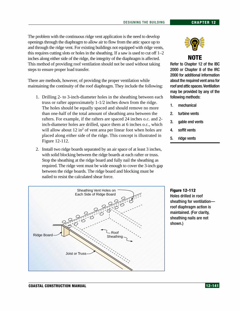
12-141COASTAL CONSTRUCTION MANUAL
CHAPTER 12DESIGNING THE BUILDING
The problem with the continuous ridge vent application is the need to developopenings through the diaphragm to allow air to flow from the attic space up toand through the ridge vent. For existing buildings not equipped with ridge vents,this requires cutting slots or holes in the sheathing. If a saw is used to cut off 1–2inches along either side of the ridge, the integrity of the diaphragm is affected.This method of providing roof ventilation should not be used without takingsteps to ensure proper load transfer.
There are methods, however, of providing the proper ventilation whilemaintaining the continuity of the roof diaphragm. They include the following:
1. Drilling 2- to 3-inch-diameter holes in the sheathing between eachtruss or rafter approximately 1-1/2 inches down from the ridge.The holes should be equally spaced and should remove no morethan one-half of the total amount of sheathing area between therafters. For example, if the rafters are spaced 24 inches o.c. and 2-inch-diameter holes are drilled, space them at 6 inches o.c., whichwill allow about 12 in2 of vent area per linear foot when holes areplaced along either side of the ridge. This concept is illustrated inFigure 12-112.
2. Install two ridge boards separated by an air space of at least 3 inches,with solid blocking between the ridge boards at each rafter or truss.Stop the sheathing at the ridge board and fully nail the sheathing asrequired. The ridge vent must be wide enough to cover the 3-inch gapbetween the ridge boards. The ridge board and blocking must benailed to resist the calculated shear force.
Figure 12-112Holes drilled in roofsheathing for ventilation—roof diaphragm action ismaintained. (For clarity,sheathing nails are notshown.)
NOTERefer to Chapter 12 of the IBC2000 or Chapter 8 of the IRC2000 for additional informationabout the required vent area forroof and attic spaces. Ventilationmay be provided by any of thefollowing methods:
1. mechanical
2. turbine vents
3. gable end vents
4. soffit vents
5. ridge vents
RoofSheathingRidge Board
Joist or Truss
Sheathing Vent Holes onEach Side of Ridge Board

12-142 FEDERAL EMERGENCY MANAGEMENT AGENCY
CHAPTER 12 DESIGNING THE BUILDING
For new construction, the designer should detail the ridge vent installationwith the proper consideration for the load transfer requirement. Where high-diaphragm loads may occur, a design professional should be consultedregarding the amount of sheathing that can be removed or other methods ofproviding ventilation while still transferring lateral loads. The need to meetthese requirements may become a significant problem in large or complexresidential buildings where numerous ventilation openings are required. Inthese instances, ridge vents may need to be augmented with other ventilatingdevices (e.g., static or gable-end vents).
Many ridge vent products are not very wide. When these products are used, itmay be difficult to provide sufficiently large openings through the sheathingand still maintain diaphragm integrity if holes are drilled through thesheathing. Manufacturers’ literature often illustrates large openings at theridge with little or no consideration for the transfer of lateral loads.
12.8 Utilities/Mechanical Equipment
12.8.1 ElevatorsElevators are being installed with increasing frequency in elevated, single-family homes in coastal areas. These elevators are used for primarily smallnumbers of people, but are large enough to provide handicap accessibility andaccommodate small pieces of household equipment.
Small personal-size elevators are almost always designed with a shaft that isinstalled away from an outside wall. The elevator shaft must have a landing,usually at the very bottom level (usually ground level), and a cab platformnear the top. The bottoms of elevators that have a landing at the lower levelare almost always below the DFE.
FEMA’s NFIP Technical Bulletin 4 (see Appendix H) discusses theinstallation of elevator equipment in the floodplain. As explained in thebulletin, elevator accessory equipment should be installed above the BFE toprevent damage. It is important to note that one of the safety features ofelevators causes them to descend to the lowest level during power outages sothat occupants will not be trapped in the cab. During flooding, this featuremay expose the cab to flood waters. For elevator installation in coastalbuildings, the designer must ensure the elevator stops at a level above the DFEwhen the power is lost. One method is to install a system of interlockingcontrols and float switches, as described in NFIP Technical Bulletin 4.
NOTEFor additional information, seeProtecting Building UtilitiesFrom Flood Damage – Prin-ciples and Practices for the De-sign and Construction of Flood-Resistant Building Utility Sys-tems, FEMA 348 (FEMA 1999).
WARNINGDesigners and builders are cau-tioned not to inadvertentlyweaken the lateral load path bycutting back the sheathing for aridge vent without providing foran alternative method of trans-ferring the loads.
DEFINITIONDFE = Design Flood Elevation
See Chapter 11, Section 11.6.2,for additional information.

12-143COASTAL CONSTRUCTION MANUAL
CHAPTER 12DESIGNING THE BUILDING
12.8.2 Design of Exterior-Mounted Mechanical EquipmentHigh winds, flooding, and seismic events are the natural hazards that can causethe greatest damage to exterior-mounted mechanical and electrical equipment.
12.8.2.1 High WindsBlowoff of exhaust fans, fan cowlings, and vent hoods commonly occursduring high winds. The resulting windblown debris can cause damage toother buildings, and water can enter the building that lost the equipment.Tearing away of the equipment typically occurs because of inadequateanchorage of the equipment to the roof, inadequate strength of the equipmentitself (i.e., loss of fan cowlings), and corrosion.
Considering the small size of most exhaust fans, vent hoods, and air-conditioning units used on residential buildings, the following prescriptiveattachment recommendations should be sufficient for most residences:
• For curb-mounted units, specify #14 screws with gasketed washers.
• For curbs with sides less than 12 inches, specify one screw at each sideof the curb.
• For curbs between 12 and 24 inches, specify two screws per side.
• For curbs between 24 and 36 inches, specify three screws per side.
• For buildings within 3,000 feet of the ocean, stainless steel screws arerecommended.
• For units that have flanges attached directly to the roof, attachment with#14 pan-head screws is recommended. A minimum of two screws perside, with a maximum spacing of 12 inches o.c., is recommended.
If the equipment is more than 30 inches above the curb, the attachment designshould be based on calculated wind loads. ASCE 7-98 does not provideadequate guidance for determining equipment loads. Until such criteria areprovided, the following approach is recommended:
• Assume a negative (i.e., uplift) load on the top of the equipment, anegative (i.e., suction) load on one side of the equipment, and apositive load on the opposite side of the equipment.
• Apply the loads to the longest side of the equipment.
• Consider the equipment as partially enclosed.
• Use component and cladding coefficients (consider the top of theequipment as the roof, and the sides as walls).
• Select coefficients for the field of the roof and field of the wall (i.e., donot use perimeter or corner coefficients).

12-144 FEDERAL EMERGENCY MANAGEMENT AGENCY
CHAPTER 12 DESIGNING THE BUILDING
Until equipment manufacturers produce more wind-resistant equipment, job-site strengthening of fan cowlings and vent hoods is recommended. Oneapproach is to use 1/8-inch-diameter stainless steel cables, as shown in Figure12-113. Two or four cables are recommended, depending on design windconditions. Alternatively, additional, heavy straps could be screwed to thecowling and curb.
To avoid corrosion problems, nonferrous metal, stainless steel, or steel withminimum G-90 hot-dip galvanized coating is recommended for theequipment itself, equipment stands, and equipment anchors when theequipment is on buildings located within 3,000 feet of the ocean. Stainlesssteel fasteners are also recommended.
12.8.2.2 Flooding Flood damage to mechanical equipment is typically caused by failure tosufficiently elevate equipment as shown in Figure 12-114. Figure 12-115shows proper elevation of an air-conditioning condenser in a floodprone area.
Figure 12-113Typhoon Paka (1997), Guam.Stainless steel cables forstrengthening fan cowlingsand vent hoods.

12-145COASTAL CONSTRUCTION MANUAL
CHAPTER 12DESIGNING THE BUILDING
Outdoor or exposed mechanical equipment for one-to-four family residentialbuildings will normally be limited to the following:
• air-conditioning condensers
• ductwork (air supply and return)
• exhaust fans
• well pumps
Flood waters can force mechanical equipment from its supports and sever itsconnection to mechanical or electrical systems. Mechanical equipment canalso be damaged or destroyed by inundation in flood waters, especially salt
Figure 12-114Hurricane Georges (1998),U.S. Gulf Coast. Mechanicalequipment damaged as aresult of insufficientelevation.
Figure 12-115Proper elevation ofmechanical equipment in afloodprone area.
12-146 FEDERAL EMERGENCY MANAGEMENT AGENCY
CHAPTER 12 DESIGNING THE BUILDING
water. A very short period of inundation may not destroy some types ofmechanical equipment, but any inundation of electrical equipment will, at aminimum, cause significant damage to wiring and other components.
Minimizing flood damage to mechanical equipment requires elevating itabove the DFE. Because of the uncertainty of wave heights and theprobability of waves splashing, the designer should consider additionalelevation for this equipment to help minimize damage.
In V zones, equipment must be installed either on a cantilevered platform (seeSection 13.6.2) supported by the first floor framing system or on an openfoundation like that used for the primary building. It is strongly recommendedthat any open foundation used to support mechanical equipment be of thesame size, depth, and structural integrity as the main building foundation.
In A zones, mechanical equipment must be elevated to the DFE on either anopen or solid foundation or otherwise protected from flood waters entering oraccumulating in the system components. For houses constructed overcrawlspaces, some HVAC systems are installed in such a way that the ductworkis routed through the crawlspace. This ductwork must be installed above theDFE or be made watertight in order to minimize flood damage. Manyductwork systems today are constructed with insulated board and thus wouldnot withstand flood inundation without being destroyed.
12.8.2.3 SeismicResidential mechanical equipment units are normally not heavy. Therefore,with some care in attachment design for resistance to shear and overturningforces, these units should perform well during seismic events. Air-conditioning units that are mounted on tall elevated platforms willexperience higher accelerations than ground-mounted units; therefore, extraattention should be given to attachment in areas prone to large groundmotion accelerations.
12.8.3 Design of Interior Mechanical EquipmentHigh winds will normally not affect the operation of indoor equipment;however, flood waters can cause substantial damage to furnaces, boilers,water heaters, and distribution ductwork. Flood waters can extinguish aflame, short-circuit the equipment’s electrical system, and inundateequipment and ductwork with sediment.

12-147COASTAL CONSTRUCTION MANUAL
CHAPTER 12DESIGNING THE BUILDING
There are only two primary methods of reducing flood damage to interiorequipment:
1. Elevate the equipment and the ductwork above the DFE. Thiselevation may be accomplished by hanging the equipment from theexisting first floor or placing the equipment in the attic or some otherlocation above the DFE.
2. Build a waterproof structure around the equipment, allowing accessfor maintenance and replacement of some of the equipment parts.
12.8.4 Electrical, Telephone, and Cable TV SystemsElectric utilities serving residential buildings in coastal areas are frequently ina harsh and corrosive environment where increased maintenance and a shorterlife can be expected. Common electrical components on residential buildingsthat might be exposed to severe wind or flood events consist of electricmeters, electric panels, electric feeds from the utility company, receptacles,lights, security system connections, and telephone connections.
The design of an electric utility system (and any other utility service) mustconsider that the success of the system depends on numerous componentsoperating successfully—all of which are at some risk of failure. For instance,if there are 10 components in the system that must operate for the system tobe successful and the reliability of each component is 95 percent, thereliability of the entire system is (0.95)10 = 60 percent. A system of this typehas a high probability of failing during a natural hazard event.
The primary method of protection is to elevate all of these components abovethe DFE; however, it frequently is not possible to accomplish this — in fact,there are conflicts between the concepts embodied in floodplain managementrequirements and other building code regulations. Depending on the DFE, thetwo most likely conflicts that are difficult to resolve involve the placement ofthe electric meter and the location of a light switch at the base of entry/exitstairs required for safe egress by the building code.
Meters are normally required to be no higher than eye level for easy readingby utility company employees; however, this height is often below theexpected flood level for coastal homes. Figure 12-116 shows an electricmeter that is easily accessible by the utility company, but that is below theDFE. Figure 12-117 shows a bank of meters and electric feeds that failedduring Hurricane Opal.
NOTEAlthough the IBC and IRCspecify that flood-resistant ma-terials be used below the BFE,this manual recommends thatflood-resistant materials beused below the DFE.

12-148 FEDERAL EMERGENCY MANAGEMENT AGENCY
CHAPTER 12 DESIGNING THE BUILDING
Traditionally, the utility company is responsible for the service to a house tothe point that is metered. The service to the house is provided eitherunderground or overhead. Underground service must be designed for floodconditions and must be buried deep enough for protection from scour anderosion. The length of the service connection from grade to the meter isusually a few feet. This short connection should be designed so that theconduit or electric cable will not be contaminated by flood water and so thatdebris will not strike the conduit or cable and disable the power.
Figure 12-116Elevated electric meter.
Figure 12-117Electric meters and feedlines that failed duringHurricane Opal (1995).

12-149COASTAL CONSTRUCTION MANUAL
CHAPTER 12DESIGNING THE BUILDING
Wind damage to exterior-mounted electrical equipment is infrequent, in partbecause of the small size of most equipment (e.g., disconnect switches andconduit). Exceptions are satellite dishes and electrical service penetrationsthrough the roof, as shown in Figure 12-118. This problem can be avoidedwith underground service. It can also be avoided by terminating the overheadlines at a service mast mounted on a freestanding concrete pylon, andproviding underground lines between the pylon and residence. A concretepylon is shown in Figure 12-119.
Figure 12-118Hurricane Marilyn (1995),U.S. Virgin Islands. Damagecaused by dropped overheadservice.
Figure 12-119Hurricane Georges (1998),Puerto Rico. Concretepylon used for overheadservice mast.

12-150 FEDERAL EMERGENCY MANAGEMENT AGENCY
CHAPTER 12 DESIGNING THE BUILDING
Other recommendations for protecting electrical system components includethe following:
• Install panel feeds and conduits on the landward side of piles or othertypes of foundation elements to protect them from floating debris andfrontal flood forces.
• Install the minimum number of switches below the DFE that will providecompliance with the electrical code. The feeds to the switch receptaclesshould come from above the DFE to minimize flood inundation.
• Install lights that are energized by a motion detector on the level belowthe DFE instead of lights operated by a switch.
• Install the feed from the utility company to the house below the groundso that damage to this connection is minimized.
• Install the electric panel above the DFE in a location that is easilyaccessible from the interior of the house.
Do not install electrical components behind or through breakaway walls.Components installed in this way are likely to be damaged when thebreakaway wall fails. In addition, they may prevent complete failure of thewall and may transfer loads into the supporting structure of the house.
Satellite dish failures are typically caused by the designer’s failure to performwind load calculations and provide for adequate anchorage.
Because a severe wind event will certainly interrupt electric service,designers and homeowners need to make decisions about the need fortemporary power. If a decision is made to install a generator in a new orexisting building, this manual recommends the following:
• Locate the generator above the DFE.
• Locate the generator so that engine exhaust fumes are vented to theoutside.
• Locate the fuel source above the DFE, and store an amount of fueladequate for the expected use and length of time the generator willoperate.
• Install the generator where its noise and vibration will cause the leastdisruption.
• Size the generator for the expected load, including the starting andrunning load. Determine what the expected load will be (e.g., does theload include heat, refrigeration, lights, sump pumps, sewer ejectorpumps). Heating and cooling require very large generators and shouldprobably be provided only for safety and freeze protection.
NOTESee Section VI-D of EngineeringPrinciples and Practices for Ret-rofitting Flood Prone ResidentialBuildings, FEMA 259 (FEMA1995), for guidance on deter-mining the proper size of anemergency generator.
12-151COASTAL CONSTRUCTION MANUAL
CHAPTER 12DESIGNING THE BUILDING
• Provide an “emergency load” subpanel to supply critical circuits. Donot rely on extension cords. Supply the emergency panel from the “loadside” of a manual or automatic transfer switch.
• Determine whether operation of the generator will be manual orautomatic. (Manual operation is simpler and less expensive.)
• Decide whether to (1) install a quick connection at the building’selectric panel so that the generator can feed the building’s electricsystem or (2) run extension cords from the generator to the selectedequipment. Protection must be provided at the panel so that generatorpower will not “back feed” into the supply line and endanger electricworkers when they are reconnecting power to the building.
12.8.5 Water and Wastewater SystemsThese systems include the following:
• wells
• septic systems
• sanitary systems
• municipal water connections
• fire sprinkler systems
12.8.5.1 WellsProtection of well systems from a severe event (primarily a flood) mustconsider the following, at a minimum:
• Flood waters that enter aquifers or that saturate the soil can contaminatethe water supply.
• Non-submersible well pumps must be above the DFE.
• If water is to be available following disasters, a alternative power sourcemust be provided.
• The water supply line riser must be protected from water and debrisflow damage; this means the supply line must be behind a pile or otherstructural member or inside an enclosure designed to also withstand theforces from the event.
• Backflow valves must be installed to prevent flood waters from flowinginto the water supply when water pressure in the supply system is lost.
WARNINGDo not “backfeed” emergencypower through the servicepanel. Utility workers can bekilled!

12-152 FEDERAL EMERGENCY MANAGEMENT AGENCY
CHAPTER 12 DESIGNING THE BUILDING
12.8.5.2 Septic SystemsProtection of septic systems must consider the following, at a minimum:
• If the septic tank is dislodged from its position in the ground, thepiping will come disconnected, releasing sewage into floodwaters, andthe tank could damage the nearest structure. Therefore, the systemmust be buried below the expected depth of erosion and scour, and thetank must be anchored to prevent a buoyancy failure
• The sewage riser lines and septic tank risers must be protected fromwater and debris flow damage; this means risers should be behind apile or other structural member or inside an enclosure designed to alsowithstand the forces from the event.
12.8.5.3 Sanitary SystemsProtection of sanitary systems must consider the following, at a minimum:
• Sanitary riser lines must be protected from water and debris flowdamage; this means risers should be behind a pile or other structuralmember or inside an enclosure designed to also withstand the forcesfrom the event.
• When the line breaks at the connection of the building line andmain sewer line, a check valve in the line may help prevent rawsewage from flowing back out of the line and contaminating thesoil near the building.
12.8.5.4 Municipal Water ConnectionsProtection of municipal water connections is accomplished primarily byprotecting the water riser into the building from damage by debris. If waterrisers are severed during a coastal event, damage to the water supply systemcan include the following:
• waste matter from flooded sewer or septic systems intruding into thewater system
• sediment filling some portion of the pipes
• breaks in the pipes at multiple locations
12.8.5.5 Fire Sprinkler SystemsProtection of this system is similar to the others - the primary issue is tolocate the sprinkler riser such that the location provides shielding fromdamage. In addition, there must be consideration to the location of shutoffvalves, etc., so that, if there is damage to an unprotected portion of the firewater supply line, this damage is not unnecessarily added to the damagecaused by the natural hazard event.
WARNINGIn some areas, high groundwa-ter levels may preclude the in-stallation of septic tanks belowthe level of expected erosionand scour.

12-153COASTAL CONSTRUCTION MANUAL
CHAPTER 12DESIGNING THE BUILDING
12.9 Appurtenant Structures
12.9.1 Decks, Gazebos, and Covered Porches Attached to Buildings
Many decks and other exterior attached structures have failed duringhurricanes. For decks and other structures without roofs, the primary causeof failure has been inadequate support — the pilings have either not beenembedded deep enough to prevent failure or have been too small to carrythe large forces from natural hazards.
The following are recommendations for the design of decks and other exteriorattached structures:
• Where possible, the deck should be supported with the same type offoundation and structural system as the primary building. If this is notpossible, care should be taken to ensure that the main building andattachment have similar stiffness.
• Either decks and other structures should be structurally independentof the main structure, or the additional forces they will generateshould be expressly considered in the design of the main structureand the attachment to the main structure. If the attachment relies onthe lateral-force-resisting system of the main structure, its anchoragemust not be allowed to fail. Unless the deck is structurallyindependent, any attachment method that is based on the “breakawaydeck” concept will create debris. Note that any construction seawardof mean high tide must be carried out in such a way that damage tothe insured structure is minimized.
• If the deck surface is constructed at floor level, the deck surface/floorlevel joint provides a point of entry for wind-driven rain. Eliminate thisproblem by lowering the deck surface below the floor level.
• Cantilevering a deck from a building eliminates the need for pilesaltogether and should be considered when the deck dimensions can beaccommodated with this structural technique. Caution must beexercised with this method to keep water out of the main houseframing. Chapter 13 discusses construction techniques for flashingcantilever decks that will minimize water penetration into the house.
• Exposure to the coastal environment is severe for decks and otherexterior appurtenant structures. Wood must be preservative-treated ornaturally decay resistant, and fasteners must be corrosion resistant.
12.9.1.1 HandrailsTo minimize the effects of wind pressure, flood forces, and wave impacts,handrails for decks should be open, with slender vertical or horizontal
WARNINGDecks should not cantilever overbulkheads or retaining wallswhere waves can run up thevertical wall and under the deck.
WARNINGThe NFIP regulations define “ap-purtenant structure” as “a struc-ture which is on the same par-cel of property as the principalstructure to be insured and theuse of which is incidental to theuse of the principal structure.”In this manual, appurtenantstructure means any other build-ing or constructed element onthe same property as the pri-mary building.
NOTESee FEMA NFIP Technical Bulle-tin 5, Free of Obstruction Re-quirements (Appendix H), for ad-ditional information about thetypes of construction allowed inCoastal High Hazard Areas.

12-154 FEDERAL EMERGENCY MANAGEMENT AGENCY
CHAPTER 12 DESIGNING THE BUILDING
members spaced in accordance with the locally adopted building code. Manydeck designs include solid panels (some made of plexiglass) between the topof the deck handrail and the deck. These solid panels must resist the designwind and flood loads (below the DFE); otherwise, they will become debris.
12.9.1.2 StairwaysMany coastal homes have stairways leading to ground level. During flooding,flood forces often move the stairs and frequently separate them from the pointof attachment. When this occurs, the stairs become debris and can causedamage to nearby houses and other buildings.
Recommendations for stairs that descend below the BFE include thefollowing:
• To the extent permitted by code, use open-riser stairs to let floodwater through the stair stringers, and anchor the stringers to apermanent foundation such as piles driven to a depth sufficient toprevent failure from scour.
• Extend the bottom of the stair carriages several feet below grade toaccount for possible scour. Stairs constructed in this fashion are morelikely to remain in place during a coastal hazard event and thereforemore likely to be usable for access after the event. In addition, bydecreasing the likelihood of damage, this approach will reduce thelikelihood of the stairs becoming debris.
• Construct the stairs so they are retractable. This requires a winch,cable, and hinged stair so that when a storm is expected, the winch canbe used to raise the stairs out of harm’s way (check local buildingcodes for construction requirements of these systems).
12.9.2 Walkways, Sidewalks, and Other Ground-Level StructuresThe walkway and sidewalk least susceptible to damage is the one that does notexist, so eliminating ground-level structures is one way a designer can reducepotential damage. In most instances, these ground-level accessories becomedebris during a flood event and can cause damage to neighboring buildings.
The designer should first consult state or local officials concerningregulations that govern ground-level structures. Some states have specificguidelines that must be followed for these types of structures. Ground-levelstructures include the following:
• wood walkways
• wood dune walkovers
• wood ground-level or near-ground-level decks
NOTESee Appendix I for guidance con-cerning the design and con-struction of dune walkovers.

12-155COASTAL CONSTRUCTION MANUAL
CHAPTER 12DESIGNING THE BUILDING
• planters
• concrete walkways
• concrete driveways
For wood structures, one of the following is recommended:
• Secure the structure with a foundation that will resist both the expectedscour and the flood force that will come up from under the structureand lift it out of the soil. Figure 12-120 illustrates this concept.
• Construct the structure in such a way that it can be removed and storedprior to the storm event.
For concrete structures, the following is recommended:
• Do not install any reinforcement in walkways or driveways locatedbelow the building
• Do not secure the concrete to any structural element of the buildingsuch as a pile or column
• Install the concrete in small segments (approximately 4 feet x 4 feet)that will easily break up during a severe storm event
• Install the concrete with a maximum thickness of 3–4 inches
Figure 12-121 (FEMA 1997) illustrates these recommendations.
Figure 12-120Wood walkover construction.
Mean High Water
Stairway Walkway
Walkway Support(Typical)
Flood Forces
ExpectedErodedProfile
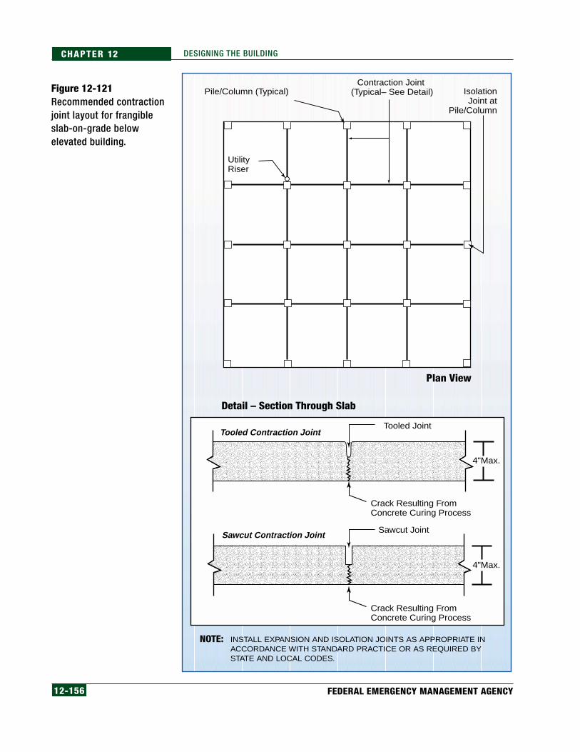
12-156 FEDERAL EMERGENCY MANAGEMENT AGENCY
CHAPTER 12 DESIGNING THE BUILDING
Figure 12-121Recommended contractionjoint layout for frangibleslab-on-grade belowelevated building.
INSTALL EXPANSION AND ISOLATION JOINTS AS APPROPRIATE IN ACCORDANCE WITH STANDARD PRACTICE OR AS REQUIRED BY STATE AND LOCAL CODES.
Pile/Column (Typical)Contraction Joint
(Typical– See Detail) IsolationJoint at
Pile/Column
Plan View
Detail – Section Through Slab
UtilityRiser
Tooled Contraction Joint
Sawcut Contraction Joint
4"Max.
4"Max.
Tooled Joint
Crack Resulting From Concrete Curing Process
Crack Resulting From Concrete Curing Process
Sawcut Joint
NOTE:

12-157COASTAL CONSTRUCTION MANUAL
CHAPTER 12DESIGNING THE BUILDING
NOTECheck with local floodplain man-agement officials for informationabout regulations governing thedisturbance of primary frontaldunes. Such regulations can af-fect various types of coastal con-struction, including the instal-lation of appurtenant structuressuch as swimming pools.
NOTEFor more information aboutelevator installation in build-ings located in SFHAs, seeFEMA NFIP Technical Bulletin4, in Appendix H.
12.9.3 Access to Elevated BuildingsThe first floor of buildings in the Special Flood Hazard Area will be elevated afew feet to many feet above the exterior grade in order to protect the buildingand its contents from flood damage. Buildings in A zones may be only a fewfeet above grade; buildings in V zones may be 8 feet to more than 12 feetabove grade. Access to these elevate buildings must be provided by one ormore of the following:
• stairs
• ramps
• elevator
Stairs must be constructed in accordance with the local building code so thatthe run and rise of the stairs conform to the requirements. Chapter 10 of theIBC and IRC require a minimum run of 11 inches per stair tread and amaximum rise of 7 inches per tread. An 8-foot elevation difference requires 11treads or almost 12 feet of horizontal space for the stairs. Local codes will alsohave requirements concerning other stair characteristics, such as stair widthand handrail height.
Ramps that comply with regulations for access by persons with disabilitiesmust have a maximum slope of 1:12 with a maximum rise of 30 inches and amaximum run of 30 feet without a level landing. The landing length must be aminimum of 60 inches. As a result, access ramps generally will not bepractical for buildings elevated more than a few feet above grade, and thenonly when adequate space is available.
Elevators are being installed in many 1- to 4-family residential structures andprovide an easy way to gain access to elevated floors of a building (includingthe first floor). There must an elevator entrance on the lowest floor; therefore,in flood hazard areas, some of the elevator equipment will be below the BFE.FEMA’s NFIP Technical Bulletin 4 provides guidance on how to installelevators so that damage to elevator components is minimized during a flood.
12.9.4 Pools and Hot TubsMany homes at or near the coast have a swimming pool or hot tub as anaccessory. Some of these pools are fiberglass and are installed on a pile-supported structural frame. Others are in-ground concrete pools. The designershould consider the following when a pool is to be installed at a coastal home:
• Only an in-ground pool may be constructed beneath an elevated V-zonebuilding. In addition, the top of the pool and the accompanying deck orwalkway must be flush with the existing grade, and the area below thelowest floor must remain unenclosed.
12-158 FEDERAL EMERGENCY MANAGEMENT AGENCY
CHAPTER 12 DESIGNING THE BUILDING
• Enclosures around pools beneath elevated buildings constituterecreational use and are therefore not allowed, even if constructed tobreakaway standards. Lattice and insect screening are allowed, becausethey do not create an enclosure under a community’s NFIP-compliantfloodplain management ordinance or law.
• A pool adjacent to an elevated V-zone building may be eitherconstructed at grade or elevated. Elevated pools must be constructedon an open foundation and the bottom of the lowest horizontalstructural member must be at or above the DFE so that the pool willnot act as an obstruction.
• The design professional must assure community officials that a poolbeneath or adjacent to an elevated V-zone building will not be subjectto breaking up or floating out of the ground during a coastal flood andwill therefore not increase the potential for damage to the foundationsand elevated portions of any nearby buildings. If an in-ground pool isconstructed in an area that can be inundated by flood waters, theelevation of the pool must account for the potential buoyancy of thepool. If a buoyancy check is necessary, it should be made with the poolempty. In addition, the design professional must design and site thepool so that any increased wave or debris impact forces will not affectany nearby buildings.
• Pools and hot tubs have water pumps, piping, heaters, filters, and otherequipment that is expensive and that can be damaged by flood watersand sediment. All such equipment should be placed above the DFEwhere practical.
• Equipment required for fueling the heater, such as electric meters orgas tanks, should be placed above the DFE. It may also be necessary toanchor the gas tank to prevent a buoyancy failure. If buried, the tankmust not be susceptible to erosion and scour and thus failure of theanchoring system.
For concrete pools, buoyancy failure is also possible when flood waters coverthe pool. In addition, flood flows can scour the soil surrounding a buried pooland tear the pool from its anchors. When this happens, the pieces of the poolbecome large waterborne debris.
12.9.5 Boat HousesIn some coastal communities that have access to waterways where boats canbe used, covered boat storage areas are sometimes constructed adjacent to thehouse. When appurtenant structures are constructed in V zones seaward ofmean high tide, these structures must be detached from the main structureand built to minimize damage to that insured structure.
CROSS-REFERENCERefer to Appendix L for de-sign guidance regardingfrangible pools.
NOTEThe construction of pools be-low or adjacent to buildings incoastal high hazard areas mustmeet the requirements pre-sented in FEMA’s NFIP Techni-cal Bulletin 5, Free of Obstruc-tion Requirements for BuildingsLocated in Coastal High HazardAreas (see Appendix H). In gen-eral, pools must either be (1) el-evated above the BFE on anopen foundation or (2) con-structed in the ground in sucha way as to minimize the ef-fects of scour and the potentialfor the creation of debris.

12-159COASTAL CONSTRUCTION MANUAL
CHAPTER 12DESIGNING THE BUILDING
The important design considerations for an appurtenant structure such as aboat house include the following:
• The roof of the appurtenant structure must be sufficiently anchored to aadequate foundation so that it will not lift off in a high-wind event.
• The appurtenant structure must be detached from the main building sothat damage to the appurtenant structure does not result in damage tothe main building.
• The structure must be adequate to carry the load of a boat being liftedfrom the water and stored during a high-wind event.
12.9.6 Storage BuildingsIn order for storage buildings to survive severe events, they must be:
• elevated above the expected flood level and anchored to resist flotation,collapse, and lateral movement, or
• anchored to resist lateral movement and wet floodproofed.
In wet floodproofing, flood waters are allowed to enter a building. When thismethod is used, the portion of the building below the expected flood levelmust be constructed of flood-resistant materials so that inundation does notcause significant damage (i.e., damage requiring more than cleanup and low-cost repair, such as painting).
Regardless of the method used, the building and/or its foundation must beprotected from erosion and scour.
Without sufficient anchorage, storage buildings exposed to flood forces willbecome large debris that can cause significant damage to nearby structures. InV zones and coastal A zones, anchoring these lightweight buildingsadequately is virtually impossible; therefore, it is recommended that storagebuildings not be placed in V zones and coastal A zones. When a storagebuilding is anchored to a foundation that resists uplift, overturning, andsliding, it is still possible for portions of the building to come apart in highwinds that cause pressures greater than the failed parts of the building weredesigned to carry. This suggests that storage buildings will fail just like housesunless an adequate load path is provided. A minimal anchoring technique forstorage buildings is illustrated in Figure 12-122.
NOTECheck with local officials to de-termine whether wet flood-proofing is allowed by localfloodplain management ordi-nances or laws.

12-160 FEDERAL EMERGENCY MANAGEMENT AGENCY
CHAPTER 12 DESIGNING THE BUILDING
12.10 ReferencesAmerican Concrete Institute. 1993. Masonry Designers’ Guide. ACI 530-92.
American Concrete Institute. 1994. Manual of Concrete Practice.
American Concrete Institute. 1999a. Building Code Requirements forMasonry Structures. ACI 530-99.
American Concrete Institute. 1999b. Building Code Requirements forStructural Concrete and Commentary. ACI 318-99.
American Forest & Paper Association. 1995. SBC High Wind Edition of theWood Frame Construction Manual for One and Two Family Dwellings.Washington, DC.
American Forest & Paper Association. 1997. National Design Specificationfor Wood Construction. Washington, DC.
American Plywood Association. 1997. Roof Sheathing Fastening Schedulesfor Wind Uplift, APA Report T325. Tacoma, WA.
American Society for Testing and Materials. 1998. Annual Book of ASTMStandards. Philadelphia, PA.
American Society of Civil Engineers. 1982. Evaluation, Maintenance andUpgrading of Wood Structures: A Guide and Commentary. New York, NY.
Figure 12-122Storage building anchoredwith strap and groundanchor. This anchoringsystem will resist only low-level flooding andmoderate winds.

12-161COASTAL CONSTRUCTION MANUAL
CHAPTER 12DESIGNING THE BUILDING
American Society of Civil Engineers. 1998a. Flood Resistant Design andConstruction. ASCE Standard ASCE 24-98.
American Society of Civil Engineers. 1998b. Minimum Design Loads forBuildings and Other Structures. ASCE Standard ASCE 7-98.
American Wood Preservers’ Association. 1994. Standards. Woodstock, MD.
Bateman, R, 1995, Nail-On-Windows, Installation & Flashing Procedures forWindows and Sliding Glass Doors, DTA, Inc.
Beall, C. 1997. Masonry Design and Detailing for Architects, Engineers, andContractors, Fourth Edition. New York: McGraw-Hill, Inc.
Bowles, J. E. 1996. Foundation Analysis and Design, Fifth Edition. McGraw-Hill, Inc.
Breyer, D. E. 1993. Design of Wood Structures, Third Edition. New York:McGraw-Hill, Inc.
Bruce; Quarles; Shelly, et. al. 1997. Wood Performance in Service, WorkshopNotes. Richmond, CA.
California Redwood Association. Redwood File. Novato, CA.
“Good Decisions: Decked Out.” Coastal Living Magazine. 1/98.
Diekmann, E. D. Undated. Diaphragms and Shearwalls, Wood Engineeringand Construction Handbook.
Dolan, J. D. 1997. Cyclic Tests of Long Shear Walls with Openings, ReportNo. TE-1996-002. Virginia Polytechnic Institute and State University,Department of Wood Science and Forest Products.
Dolan, J. D. 1997. Monotonic Tests of Long Shear Walls with Openings,Report No. TE-1996-001. Virginia Polytechnic Institute and State University,Department of Wood Science and Forest Products.
Dost, W. 1986. Performance of Wood Construction Materials, Kapalua BayVillas, WBRC Report 35.04.20. Richmond, CA.
Federal Emergency Management Agency. 1995. Engineering Principles andPractices for Retrofitting Flood Prone Residential Buildings. FEMA 259.January.

12-162 FEDERAL EMERGENCY MANAGEMENT AGENCY
CHAPTER 12 DESIGNING THE BUILDING
Federal Emergency Management Agency. 1997. Hurricane Fran in NorthCarolina – Observations, Recommendations, and Technical Guidance.FEMA 290.
Federal Emergency Management Agency. 1999. Principles and Practices forFlood-Resistant Building Utilities. FEMA 348.
Forest Products Research Society. 1988. Wood Protection Techniques and theUse of Treated Wood in Construction. Madison, WI.
Forest Products Society. 1996. Selection and Use of Preservative-TreatedWood. Forest Products Research Society. Madison, WI.
Graham and Womack. 1972. Wood-Metal Corrosion, An Annotated Survey,Research Bulletin. Oregon State University College of Forestry, ForestResearch Laboratory. Corvallis, OR.
Hamilton, P. 1997. Journal of Light Construction. March.
Highley, S. 1989. Controlling Decay in Waterfront Structures. ForestProducts Laboratory.
International Code Council. 2000a. International Building Code.Birmingham, AL.
International Code Council. 2000b. International Residential Code for One-and Two-Family Residences. Birmingham, AL.
MacGregor, J. G. 1997. Reinforced Concrete Mechanics and Design, ThirdEdition. Prentice Hall.
Masonry Institute of America. 1998. 1997 Masonry Codes and Specifications.CRC Press.
McDonald; Falk; Williams; Winandy. 1996. Wood Decks, Materials,Construction and Finishing. Forest Products Society.
McMullen Company, Inc. 1994. California Firestorm 1993, A StructuralSurvivability Survey, October 27 – 29. Davis, California.
Meyer, R.W.; Kellogg, R.M. 1982. Structural Use of Wood in AdverseEnvironments. New York, NY: Van Nostrand Reinhold.
Naaman, A. E. 1982. Prestressed Concrete Analysis and Design. New York:McGraw-Hill, Inc.

12-163COASTAL CONSTRUCTION MANUAL
CHAPTER 12DESIGNING THE BUILDING
National Association of Home Builders Research Center. 1994. Building withAlternatives to Lumber and Plywood.
National Evaluation Service, Inc., 1997, National Evaluation Report NER-272, (available from BOCA, ICBO, SBCCI).
National Roofing Contractors Association. 1996. The NRCA Roofing andWaterproofing Manual. Fourth Edition.
National Timber Piling Council, Inc. 1995. Technical Guidelines forConstruction With Treated Round Timber Pilings. January.
Peterka, J. A. et al. 1997. “Wind Uplift Model for Asphalt Shingles,” Journalof Architectural Engineering.
Rogers, S. M. “Foundations and Breakaway Walls of Small Coastal Buildingsin Hurricane Hugo,” Proceedings of Coastal Zone ‘91. American Society ofCivil Engineers.
Schein, E. 1968. The Influence of Design on Exposed Wood in Buildings in thePuget Sound Area. Pacific NW Forest and Range Experiment Station, USDA.Portland, OR,
Southern Building Code Congress International. 1997a. Standard forHurricane Resistant Construction. SSTD 10-97. Birmingham, AL.
Southern Building Code Congress International. 1997b. Test Standard forDetermining Wind Resistance of Concrete or Clay Tile Roofs. SSTD 11-97.Birmingham, AL.
Tung, C.C.; B. Kasal, S.M.; Rogers, Jr.; S.C. Yeh. 1998. Behavior ofBreakaway Wall Subjected to Wave Forces: Analytical and ExperimentalStudies. North Carolina State University.
U.S. Department of the Navy. 1982. Foundation and Earth Structures. DesignManual 7.2. Alexandria, VA.
Wood Products Promotion Council. 1996. Guide to Wood Construction inHigh Wind Areas. August.