design of interval power system stabilizer
TRANSCRIPT

8/11/2019 Design of Interval Power System Stabilizer
http://slidepdf.com/reader/full/design-of-interval-power-system-stabilizer 1/8
Abstract — This paper presents the performance of an application
of latest development of type1 fuzzy logic which is interval type2
fuzzy logic as a Power System Stabilizer (PSS). Interval Type2 Fuzzy
Logic PSS (IT2FLPSS) is a proportional-derivative type fuzzy logic
PSS consists of interval type2 fuzzy logic controller and adjustable
proportional and derivative gain. IT2FLPSS uses rotor speed
deviation as a main input and armature power as auxiliary input.
Simulations are done with several fault tests at transmission line onK undur Test System. As reference Type1 Fuzzy Logic PSS
(T1FLPSS), IEEE PSS4B (Multi Band PSS) and IEEE PSS2B (dw
PSS) from IEEE std 421.5 have been used to be compared to
IT2FLPSS. The result shows that power transfer response using
IT2FLPSS has a settling time 5.36s and overshoot level 126.35 MW
in fault normally cleared simulation. For fault cleared with one line
outage simulation, the system has settling time 8.07s with overshoot
value 68.41 MW. Similarly, for voltage deviation and armature
power deviation responses, application IT2FLPSS shows great
improvement.
Keywords — Interval Type-2 Fuzzy Logic, Power System
Stabilizer.
I. I NTRODUCTION
LECTRICAL power system generally consists of some
generating unit, transmission line, and load center. The
fault is always occurred in the electrical power system,
whether it is a permanent one or temporary one. The fault in
electrical power system can caused deviation on system’s
variables, such as voltage, frequency and others. This
deviation can affect the stability of system. Stability in
electrical power system is defined as an ability of electrical
power system to maintain synchronization during and after
fault occurred.
Power System Stabilizer (PSS) has function to maintain
electrical power system stability [1, 2, 3]. Most PSS used in
electrical power system is developed from the classical linear
control theory. Linear control theory is based on a linear
model of a fixed power system configuration. In other words, a
fixed-parameters PSS, called a conventional PSS is optimum
for one set of operating conditions and may not be as effective
for drastically different set of operating condition [2].
Imam Robandi, PhD, is with Department of Electrical Engineering, Institut
Teknologi Sepuluh Nopember (ITS), K ampus ITS, Sukolilo, Surabaya 60111,
Indonesia (e-mail: [email protected]).
Bedy K harisma is senior student of ITS, and he is now under supervised by Dr. Imam Robandi in his final project.
Nowadays PSS has possibility to be designed and
implemented with a new controller based on a modern and
sophisticated technology such as artificial intelligent. In
artificial intelligent methods, fuzzy logic is really interesting,
because it does not need mathematical approach to give
control solution.
Fuzzy logic and fuzzy sets are fundamental element for
fuzzy systems, where their objective is to model brainmanipulates inexact information. So this method is suitable for
a complex system and non-linear [4, 5]. Fuzzy set is
introduced first time by Zadeh in 1965 to manipulate data and
information which unprobabilistic and uncertain.
Further development on type1 fuzzy set is interval type2
fuzzy set. Interval type2 fuzzy set is used to model uncertainty
and imprecision in a better way. Interval type2 fuzzy set is
introduced at the first time at 1975 by Zadeh and developed by
Mendel with characterizing interval type2 fuzzy set as
Footprint of Uncertainty (FOU). FOU is limited by superior
and inferior type1 membership function [6, 7]. The
development of fuzzy set from type1 to interval type2 in mostcases always shows a better result [8].
In order to obtain the performance improvement of the
electrical power system, Interval Type2 Fuzzy Logic PSS
(IT2FLPSS) is proposed. In the IT2FLPSS application,
K undur Test System is used as test plant in conditions of fault
normally cleared and fault cleared with one line outage. In this
paper, the application of IT2FLPSS is compared with the Type
1 Fuzzy Logic PSS (T1FLPSS), dw PSS, and Multi Band PSS
(MB PSS). Three parameters are observed, voltage deviation,
power armature deviation and power transfer deviation. A
good PSS is a PSS which can maintain system’s
synchronization with minimum overshoot and settling time at
each observed parameters. The result is quite promising that
power transfer response using IT2FLPSS has a settling time
5.36s and overshoot level 126.35 MW in fault normally
cleared simulation. For fault cleared with one line outage
simulation, the system has settling time 8.07s with overshoot
value 68.41 MW. From these result IT2FLPSS can greatly
improve the system stability. Similarly, for voltage deviation
and armature power deviation responses, application
IT2FLPSS shows great improvement.
II. K UNDUR TEST SYSTEM AND POWER SYSTEM STABILIZER
K undur Test System is a system known worldwide as a
simple system on behalf of a general electricity system.
Design of Interval Type-2 Fuzzy Logic Based
Power System StabilizerImam Robandi, and Bedy K harisma
E
PROCEEDI NGS OF WORLD ACADEMY OF SCIE NCE, E NGI NEERI NG A ND TECH NOLOGY VOLUME 31 JULY 2008 ISS N 1307-6884
PWASET VOLUME 31 JULY 2008 ISS N 1307-6884 683 © 2008 WASET.ORG
International Journal of Electrical and Electronics Engineering 3:10 2009
593

8/11/2019 Design of Interval Power System Stabilizer
http://slidepdf.com/reader/full/design-of-interval-power-system-stabilizer 2/8
Despite its small size, it mimics very closely the behavior of
typical systems in actual operation. The K undur Test System is
used as a plant for PSS implementation.
A. Kundur Test System
The K undur Test System is shown in Fig. 1 that consists oftwo fully symmetrical areas linked together by two 230 kV
lines of 220 km length. Each area is equipped with two
identical round rotor synchronous acts as thermal plant
generators rated 20kV/900MVA connected to transformer (T1,
T2, T3, and T4) . The synchronous machines (G1, G2, G3, and
G4) in all area have identical parameters, except for inertia
which is H = 6.5s for all generators in Area 1 and H = 6.175s
for all generators in Area 2. Thermal generating plants having
identical speed regulators and fast static exciters with a 200
gain at all locations. Each generator produces 700 MW. The
loads are assumed everywhere as constant impedance load.
The Area 1 and Area 2 loads are 967 MW (L1) and 1767 MW(L2) respectively. The load voltage profile was improved by
installing 187 MVAr capacitors (C1 and C2) in each area to
make closer to unity. Area 1 is exporting to Area 2 through
two tie-lines and a single tie-line with power transfer level 413
MW and 353 MW, respectively. [2,3,9].
Fig. 1 K undur Test System
B. dw PSS
The dw PSS provides an auxiliary signal control to
excitation system based on moderate phase advance at
frequencies in order to compensate inherent lag between the
field excitation and the electrical torque . The dw PSS consists
of Sensor Time Constant, Gain, Wash Out Filter, Lead-Lag
Compensator, and a limiter. The dw PSS model is shown in
Fig. 2.
Fig. 2 dw PSS [9]
The model consists of a low-pass filter, a general gain, a
washout high-pass filter, a phase-compensation system, and an
output limiter. Functions of each block are explained as
follows:
1) Sensor
Sensor block is a first order low-pass filter. Its function is
to filter input signal.
2) Overall Gain
Overall Gain’s function to regulate amplifying level of
input signal.3) Wash-out
Washout is a filter works as high pass filter for the input
signal.
4) Lead-Lag Compensator
Lead-lag compensator works as phase-lead and phase–lag
compensator of excitation system.
5) Limiter
Limiter works to limit the output of PSS before the output
signal goes to excitation Systems.
Values of dw PSS’s parameters are presented in Table I.
TABLE IDW PSS’S PARAMETER
Parameter Value
Sensor time constant (Ts) 15 10-3s
Wash-Out time constant (Tw) 10s
Overall Gain (K ) 30
Lead-Lag #1Time constant (T1n) 50 10-3s
Lead-Lag #1 Time constant (T1d) 20 10-3s
Lead-Lag #2 Time constant (T2n) 3s
Lead-Lag #2 Time constant (T2d) 5.4s
Limiter -0.15 to 0.15
C.
MB PSS
Multi Band PSS (MB PSS) is designed to damp all the
disturbances occurring in an electrical power system. The
disturbance induces electromechanical oscillations to electrical
generators on system. Electromechanical oscillations can be
classified in four main categories as explained as follows:
1) Local oscillations: it is caused by a fault occurred between
a unit and the rest of the generating station and between the
latter and the rest of the power system. Their frequencies
typically range from 0.8 to 4.0 Hz.
2) Interplant oscillations: it is caused by a fault occurred
between two electrically close generation plants.
Frequencies can vary from 1 to 2 Hz.3) Inter-area oscillations: it is caused by a fault occurred
between two major groups of generation plants.
Frequencies are typically in a range of 0.2 to 0.8 Hz.
4) Global oscillation: characterized by a common in-phase
oscillation of all generators as found on an isolated system.
The frequency of such a global mode is typically under 0.2
Hz.
These oscillations, also called power swings, must be
effectively damped to maintain the system's stability. Multi
Band PSS (MB PSS) provides damping action using three
separate working bands to damp all oscillation frequency
spectrums that may be occurred at electrical power system.
PROCEEDI NGS OF WORLD ACADEMY OF SCIE NCE, E NGI NEERI NG A ND TECH NOLOGY VOLUME 31 JULY 2008 ISS N 1307-6884
PWASET VOLUME 31 JULY 2008 ISS N 1307-6884 684 © 2008 WASET.ORG
International Journal of Electrical and Electronics Engineering 3:10 2009
594

8/11/2019 Design of Interval Power System Stabilizer
http://slidepdf.com/reader/full/design-of-interval-power-system-stabilizer 3/8
Three separate bands are used, respectively dedicated to the
low-, intermediate-, and high-frequency modes of those
oscillations: the low band is typically associated with the
power system global mode, the intermediate with the inter-area
modes, and the high with the local modes. MB PSS model is
shown in Fig. 3.
Fig. 3 Multi Band PSS
Each of the three bands is made of a differential band pass
filter, a gain, and a limiter. Functions of each block are
explained as follows:
1) Speed Transducers
Speed Transducer’s function is to change rotor speed
deviation as input signal into frequency.
2) Low Frequency Band [FL K L]
Low Frequency Band is a high pass filter. Its function is to
filter low frequency oscillation mode.
3) Intermediate Frequency Band [FI K I]
Intermediate Frequency Band is a high pass filter. Its
function is to filter Intermediate frequency oscillation
mode.
4) High Frequency Band [FH K H]
High Frequency Band is a high pass filter. Its function is to
filter high frequency oscillation mode.
5) Signal Limiter [VLMAX-MIN VlMAX-MIN VHMAX-MIN]
Signal Limiter’s function is to limits the output signal of
each band pass filter and MB PSS final limiter
6) Final Limiter [VSTMAX-STMIN]
Final Limiter’s function is to limit total sum of band pass
filter outputs.
Values of MB PSS’s parameters are presented in Table II.
TABLE II
MB PSS’S PARAMETERS
Parameter Value
FL 0.2Hz
K L 30
FI 1.25Hz
K I 40
FH 12.0Hz
K H 160
VLMAX-MIN -0.075 to 0.0175
VlMAX-MIN -0.15 to 0.15
VHMAX-MIN 0.15 to 0.15VSTMAX-MIN 0.15 to 0.15
III. PROPOSED I NTERVAL TYPE2 FUZZY LOGIC PSS I N
APPLICATION
An Interval Type2 Fuzzy Logic PSS is similar with Type1
Fuzzy Logic PSS, but instead using type1 Fuzzy Logic as a
controller IT2FLPSS uses Interval Type2 Fuzzy Logic as the
controller. The explanation about Interval Type2 Fuzzy Logic
and its application, IT2FLPSS, are explained as follows:
A. Interval Type2 Fuzzy Logic
Membership function in interval type2 fuzzy logic set as an
area called Footprint of Uncertainty (FOU) which limited by
two type1 membership function those are: Upper membership
Function (UMF) and Lower Membership function (LMF)
[6,7]. Interval type2 membership function is shown in Fig. 4.
Fig. 4 Membership Function Interval Type2 Fuzzy Logic Set
Operation at Interval type-2 fuzzy set is identical with an
operation on type-1 fuzzy set, however on interval type-2
fuzzy system; fuzzy operator is done at two type1 membership
function which limits the FOU, UMF and LMF to produce
firing strenght. Operation on interval type2 fuzzy logic is
shown in Fig. 5.
Fig. 5 Operation on Interval Type2 Membership Function
Fuzzy Inference System (FIS) which used in this paper is
Mamdani method, or used to call Max-Min method. On
Mamdani FIS it needs 5 steps to produce an output:
Fuzzyfication, Membership function operation, Implication
function, Aggregation, and Defuzzyfication. A simple example
of Mamdani Fuzzy Inference System on “dinner for two” [10]
on interval type2 fuzzy logic system is shown in Fig. 6.
Defuzzyfication is a mapping process from fuzzy logic
control action area to a non-fuzzy (crisp) control action area.
Defuzzyfication on an interval type2 fuzzy logic system thatuse centroid method has been proposed by K arnik and
PROCEEDI NGS OF WORLD ACADEMY OF SCIE NCE, E NGI NEERI NG A ND TECH NOLOGY VOLUME 31 JULY 2008 ISS N 1307-6884
PWASET VOLUME 31 JULY 2008 ISS N 1307-6884 685 © 2008 WASET.ORG
International Journal of Electrical and Electronics Engineering 3:10 2009
595
8/11/2019 Design of Interval Power System Stabilizer
http://slidepdf.com/reader/full/design-of-interval-power-system-stabilizer 4/8
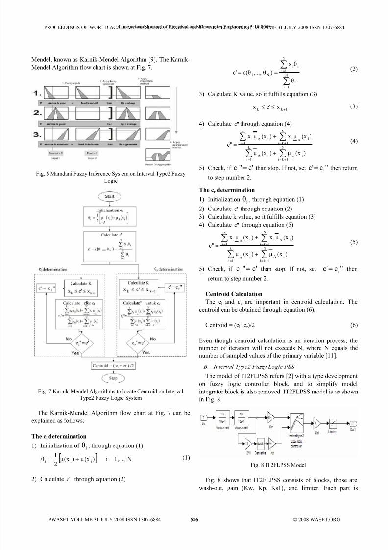
Mendel, known as K arnik-Mendel Algorithm [9]. The K arnik-
Mendel Algorithm flow chart is shown at Fig. 7.
Fig. 6 Mamdani Fuzzy Inference System on Interval Type2 Fuzzy
Logic
Fig. 7 K arnik-Mendel Algorithms to locate Centroid on Interval
Type2 Fuzzy Logic System
The K arnik-Mendel Algorithm flow chart at Fig. 7 can be
explained as follows:
The cl determination
1) Initialization ofi
θ , through equation (1)
[ ] N1,...,i ,)(xµ)(xµ2
1θ iii =+= (1)
2) Calculate 'c through equation (2)
∑
∑
=
=== N
1i
i
N
1i
ii
Ni
θ
θx
)θ,...,c(θc' (2)
3) Calculate K value, so it fulfills equation (3)
1k k xc'x+
≤≤ (3)
4) Calculate "c through equation (4)
∑∑
∑∑
+==
+==
+
+
= N
1k i
iA
k
1i
iA
N
1k i
iAi
k
1i
iAi
)(xµ)(xµ
)(xµx)(xµx
c" (4)
5) Check, if c'"cl = than stop. If not, set "cc' l= then return
to step number 2.
The cr determination1) Initialization
iθ , through equation (1)
2) Calculate 'c through equation (2)
3) Calculate k value, so it fulfills equation (3)
4) Calculate "c through equation (5)
∑∑
∑∑
+==
+==
+
+
= N
1k i
iA
k
1i
iA
N
1k i
iAi
k
1i
iAi
)(xµ)(xµ
)(xµx)(xµx
c" (5)
5) Check, if c'"c r = than stop. If not, set "cc' r
= then
return to step number 2.
Centroid Calculation
The cl and cr are important in centroid calculation. The
centroid can be obtained through equation (6).
Centroid = (cl+cr )/2 (6)
Even though centroid calculation is an iteration process, the
number of iteration will not exceeds N, where N equals the
number of sampled values of the primary variable [11].
B. Interval Type2 Fuzzy Logic PSS
The model of IT2FLPSS refers [2] with a type development
on fuzzy logic controller block, and to simplify modelintegrator block is also removed. IT2FLPSS model is as shown
in Fig. 8.
Fig. 8 IT2FLPSS Model
Fig. 8 shows that IT2FLPSS consists of blocks, those arewash-out, gain (K w, K p, K s1), and limiter. Each part is
PROCEEDI NGS OF WORLD ACADEMY OF SCIE NCE, E NGI NEERI NG A ND TECH NOLOGY VOLUME 31 JULY 2008 ISS N 1307-6884
PWASET VOLUME 31 JULY 2008 ISS N 1307-6884 686 © 2008 WASET.ORG
International Journal of Electrical and Electronics Engineering 3:10 2009
596
8/11/2019 Design of Interval Power System Stabilizer
http://slidepdf.com/reader/full/design-of-interval-power-system-stabilizer 5/8
explained as follows:
1) Wash Out
This block consists of two wash-out filter with time
constant 10 second.
2) Gain [K w K p K s1]
Gain is needed to normalize the input and output of fuzzylogic controller.
3) Fuzzy Logic Controller
Fuzzy Logic Controller has a function to produce control
signal as an output appropriate with the input.
4) Limiter [Vsmin Vsmax]
Limiter gives limitation of the PSS output.
In order to set fuzzy logic controller, input membership
function, output membership function, rules, and gain tuning
are definitive. Detail of input membership function, output
membership function, rules, and gain tuning are as follows:
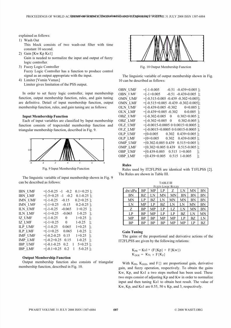
Input Membership Function
Each of input variables are classified by Input membership
function consists of trapezoidal membership function and
triangular membership function, described in Fig. 9.
-6 -4 -2 0 2 4 60
0.5
1
Fig. 9 Input Membership Function
The linguistic variable of input membership shown in Fig. 9
can be described as follows:
IBN _ UMF =[-5-0.25 -1 -0.2 0.1+0.25 ];
IBN _ LMF =[-5+0.25 -1 -0.2 0.1-0.25 ];
IMN _ UMF =[-1-0.25 -0.15 0.2+0.25 ];
IMN _ LMF =[-1+0.25 -0.15 0.2-0.25 ];
ILN _ UMF =[-1-0.25 -0.065 1+0.25 ];
ILN _ LMF =[-1+0.25 -0.065 1-0.25 ];
IZ_ UMF =[-1-0.25 0 1+0.25 ];
IZ_ LMF =[-1+0.25 0 1-0.25 ];
ILP _ UMF =[-1-0.25 0.065 1+0.25 ];
ILP _ LMF =[-1+0.25 0.065 1-0.25 ];IMP _ UMF =[-0.2-0.25 0.15 1+0.25 ];
IMP _ LMF =[-0.2+0.25 0.15 1-0.25 ];
IBP _ UMF =[-0.1-0.25 0.2 1 5+0.25 ];
IBP _ LMF =[-0.1+0.25 0.2 1 5-0.25 ];
Output Membership Function
Output membership function also consists of triangular
membership function, described in Fig. 10.
-1.5 -1 -0.5 0 0.5 1 1.50
0.1
0.2
0.3
0.4
0.5
0.6
0.7
0.8
0.9
1
Fig. 10 Output Membership Function
The linguistic variable of output membership shown in Fig.
10 can be described as follows:
OBN _ UMF =[-1-0.005 -0.51 -0.439+0.005 ];
OBN _ LMF =[-1+0.005 -0.51 -0.439-0.005 ];
OMN _ UMF =[-0.515-0.005 -0.439 -0.302+0.005];
OMN _ LMF =[-0.515+0.005 -0.439 -0.302-0.005];
OLN _ UMF =[-0.439-0.005 -0.302 0+0.005 ];
OLN _ LMF =[-0.439+0.005 -0.302 0-0.005 ];
OBZ_ UMF =[-0.302-0.005 0 0.302+0.005 ];
OBZ_ LMF =[-0.302+0.005 0 0.302-0.005 ];
OLZ_ UMF =[-0.0015-0.0005 0 0.0015+0.0005 ];
OLZ_ LMF =[-0.0015+0.0005 0 0.0015-0.0005 ];
OLP _ UMF =[0-0.005 0.302 0.439+0.005 ];
OLP _ LMF =[0+0.005 0.302 0.439-0.005 ];
OMP _ UMF =[0.302-0.005 0.439 0.515+0.005 ];
OMP _ LMF =[0.302+0.005 0.439 0.515-0.005 ];
OBP _ UMF =[0.439-0.005 0.515 1+0.005 ];
OBP _ LMF =[0.439+0.005 0.515 1-0.005 ];
Rules
Rules used by IT2FLPSS are identical with T1FLPSS [2].
The Rules are shown in Table III.
TABLE III
FUZZY LOGIC R ULES
dw\dPa BP MP LP Z LN MN BN
BN BZ LN MN MN BN BN BN
MN LP BZ LN MN MN BN BN
LN MP LP BZ LN LN MN BN
Z BP MP LP LZ LN MN BN
LP BP MP LP LP BZ LN MN
MP BP BP MP MP LP BZ LN
BP BP BP BP MP MP LP BZ
Gain Tuning
The gains of the proportional and derivative actions of the
IT2FLPSS are given by the following relations:
K PR = K s1× (F{K p} + F{K w})
K DER = K s1 × F{K P}
With K PR , K DER , and F{} are proportional gain, derivative
gain, and fuzzy operation, respectively. To obtain the gains
K w, K p, and K s1 a two steps method has been used. These
two steps consist of adjusting K p and K w in order to normalize
input and then tuning K s1 to obtain best result. The value of
K w, K p, and K s1 are 0.55, 50 x K p, and 3, respectively.
PROCEEDI NGS OF WORLD ACADEMY OF SCIE NCE, E NGI NEERI NG A ND TECH NOLOGY VOLUME 31 JULY 2008 ISS N 1307-6884
PWASET VOLUME 31 JULY 2008 ISS N 1307-6884 687 © 2008 WASET.ORG
International Journal of Electrical and Electronics Engineering 3:10 2009
597

8/11/2019 Design of Interval Power System Stabilizer
http://slidepdf.com/reader/full/design-of-interval-power-system-stabilizer 6/8
IV. R ESULT AND A NALYSIS
To see the performance of PSS on electrical power system,
fault simulation is demonstrated with connecting a 3 phase-
ground fault block at the middle of transmission line (Fault
Point A) for 8 cycles, in normally cleared condition and
cleared with one line outage condition.
A. Fault Normally Cleared
In this simulation, K undur Test System is demonstrated
under a fault simulation and then cleared without any line
outage. While fault occurred in electrical power system, it can
deviates power armature that can cause swing on generator,
affect generator voltage output and area power transfer level
until the fault is cleared [1]. When fault is cleared, system will
oscillate to return on its stable point. Electrical power transfer
level from Area1 to Area2, voltage deviation response at G1,
and power armature deviation response at G1 are shown in
Fig. 11 until Fig. 13.
0 200 400 600 800 1000 1200 1400 1600 1800 2000150
200
250
300
350
400
450
500
550
600
time (1/100 s)
M e g a W a t t ( M W )
Electrical Power Transfer Level
dw PSS
MB PSS
T1FLPSS
IT2FLPSS
Fig. 11 Electrical Power Transfer Response on Fault Normally
Cleared Simulation
0 200 400 600 800 1000 1200 1400 1600 1800 20000.9
0.95
1
1.05
1.1
1.15
time (1/100 s)
p e r u n i t ( p u )
Voltage Output at G1
dw PSS
MB PSS
T1FLPSS
IT2FLPSS
Fig. 12 Voltage Output Response on Fault Normally Cleared
Simulation
0 200 400 600 800 1000 1200 1400 1600 1800 2000-0.3
-0.2
-0.1
0
0.1
0.2
0.3
0.4
time(1/100 s)
p e r u n i t ( p u )
Power Armature at G1
dw PSS
MB PSS
T1FLPSS
IT2FLPSS
Fig. 13 Power Armature Response on Fault Normally Cleared
Simulation
B. Fault Cleared with One Line Outage
In this simulation, K undur Test System is demonstratedunder a fault simulation and then cleared with opening breaker
on line which fault occurred. Disconnecting one of two tie-line
transmission lines can change the area power transfer level
into single-line power transfer level [1]. System will oscillate
to its new stable point, during that time system parameters will
deviate. Power transfer from Area1 to Area2, voltage deviation
response at G1, and power armature deviation response at G1
are observed and shown in Fig. 14 until Fig. 16.
0 200 400 600 800 1000 1200 1400 1600 1800 2000150
200
250
300
350
400
450
500
time(1/100 s)
M e g a W a t t ( M W )
Electrical Power Transfer Level
dw PSS
MultiBand PSS
T1FLPSS
IT2FLPSS
Fig. 14 Electrical Power Transfer Response on Fault Cleared With
One Line Outage Simulation
PROCEEDI NGS OF WORLD ACADEMY OF SCIE NCE, E NGI NEERI NG A ND TECH NOLOGY VOLUME 31 JULY 2008 ISS N 1307-6884
PWASET VOLUME 31 JULY 2008 ISS N 1307-6884 688 © 2008 WASET.ORG
International Journal of Electrical and Electronics Engineering 3:10 2009
598

8/11/2019 Design of Interval Power System Stabilizer
http://slidepdf.com/reader/full/design-of-interval-power-system-stabilizer 7/8
0 200 400 600 800 1000 1200 1400 1600 1800 20000.9
0.95
1
1.05
1.1
1.15
time(1/100 s)
p e r u n i t ( p u )
Voltage Output at G1
dw PSS
MB PSS
T1FLPSS
IT2FLPSS
Fig. 15 Voltage Output Response on Fault Cleared With One Line
Outage Simulation
0 200 400 600 800 1000 1200 1400 1600 1800 2000-0.15
-0.1
-0.05
0
0.05
0.1
0.15
0.2
0.25
0.3
0.35
time (1/100 s)
p e r u n i t ( p u )
Power Armature at G1
dw PSSMB PSS
T1FLPSS
IT2FLPSS
Fig. 16 Power Armature Response on Fault Cleared With One Line
Outage Simulation
To evaluate the overshoot value and settling time clearly,
the data of PSS performances are shown on Table IV and
Table V.
TABLE IV
FAULT NORMALLY CLEARED
Power
Transfer Level
Voltage
Output at G1
Armature Power
at G1PSS
Typeovershoot Settling
time
overshoot Settling
time
overshoot Settling
time
dw PSS 137.27 3.54 0.1112 2.68 0.3322 2.98
MB PSS 158.6083 14.34 0.1360 2.40 0.3321 3.26
T1FLPSS 143.0345 5.88 0.1197 2.56 0.3257 3.14
T2FLPSS 126.3580 5.36 0.1056 2.31 0.3257 2.81
TABLE V
FAULT CLEARED WITH O NE LINE OUTAGE
Power Transfer
Level Voltage
Output at G1 Armature Power
at G1 PSS
Typeovershoot Settling
time
overshoot Settling
time
overshoot Settling
time
dw PSS 74.7314 >20 0.1222 >20 0.3322 3.61
MB PSS 63.7735 10.42 0.1511 6.53 0.3321 3.20
T1FLPSS 71.2886 10.87 0.1346 9.29 0.3257 2.92
T2FLPSS 68.4138 8.07 0.1246 6.39 0.3257 2.75
V. CONCLUSION
The IT2FLPSS proposed in this paper has been verified by
means of digital simulations of a K undur Test System in two
fault simulations. From the simulations IT2FLPSS shows
better performance than dw PSS, Multi Band PSS and
T1FLPSS. For power transfer response IT2FLPSS able to
return system to its stable points at 5.36 second with overshoot
value 126.35 MW in fault normally cleared simulation and it
achieves its new stable point at 8.07 second with overshoot
value 68.41 MW in fault cleared with one line outage.
For voltage output at G1 response IT2FLPSS able to return
system to its stable points at 2.31 second with overshoot value
0.1056 pu in fault normally cleared simulation and it achieves
its new stable point at 6.39 second with overshoot value
0.1246 in fault cleared with one line outage.
For armature power at G1 response IT2FLPSS able to
return system to its stable points at 2.81 second with overshoot
value 0.3257 pu in fault normally cleared simulation and itachieves its new stable point at 2.75 second with overshoot
value 0.3257 in fault cleared with one line outage.
R EFERENCES
[1] Imam Robandi, “Modern Power System Design” (Desain System
Tenaga Modern, in Bahasa Indonesia), Andi Offset Publisher: 2006.
[2] M. Dobrescu, I. K amwa, “A New Fuzzy Logic Power System Stabilizer
Performances”, IEEE, 2004.
[3] P. K undur, “Power System Stability and Control”, McGraw-Hill,1993.
[4] Timothy J. Ross, “Fuzzy Logic with engineering Applications”,
McGraw-Hill, 1997.
[5] ...., “Fuzzy Logic Toolbox for Use with MATLAB”, The Mathworks,
2002.[6] QilianLiangand, Jerry M. Mendel, “Interval Type-2 Fuzzy Logic System
Theory and Design”, IEEE, October, 2000.
[7] Jerry M. Mendel, Robert I.Bob John, “Type-2 Fuzzy Sets Made
Simple”, IEEE, April, 2002.
[8] Juan R. Castro, Oscar Castillo, “Interval Type-2 Fuzzy Logic for
Intelligent Control Applications”, IEEE, 2007.
[9] . ……, MATLAB help version 7.1.0.246 (R14) Service Pack 3, 2005.
[10] . ……, Fuzzy Logic Toolbox for use with MATLAB user’s guide,
version 2, 1998.
[11] Jerry M.Mendel, Feilong Liu, “Super-Exponential Convergence of the
K arnik–Mendel Algorithms for Computing the Centroid of an Interval
Type-2 Fuzzy Set”, IEEE, April 2007.
PROCEEDI NGS OF WORLD ACADEMY OF SCIE NCE, E NGI NEERI NG A ND TECH NOLOGY VOLUME 31 JULY 2008 ISS N 1307-6884
PWASET VOLUME 31 JULY 2008 ISS N 1307-6884 689 © 2008 WASET.ORG
International Journal of Electrical and Electronics Engineering 3:10 2009
599

8/11/2019 Design of Interval Power System Stabilizer
http://slidepdf.com/reader/full/design-of-interval-power-system-stabilizer 8/8
LIST OF ABREVIATION
Abbreviation Contraction
IBN _ UMF Input Big Negative Upper Membership Function
IBN _ LMF Input Big Negative Lower Membership Function
IMN _ UMF Input Medium Negative Upper Membership Function
IMN _ LMF Input Medium Negative Lower Membership Function
ILN _ UMF Input Low Negative Upper Membership Function
ILN _ LMF Input Low Negative Lower Membership Function
IZ_ UMF Input Zero Upper Membership Function
IZ_ LMF Input Zero Lower Membership Function
ILP _ UMF Input Low Positive Upper Membership Function
ILP _ LMF Input Low Positive Lower Membership Function
IMP _ UMF Input Medium Positive Upper Membership Function
IMP _ LMF Input Medium Positive Lower Membership Function
IBP _ UMF Input Big Positive Upper Membership Function
IBP _ LMF Input Big Positive Lower Membership Function
OBN _ UMF Output Big Negative Upper Membership Function
OBN _ LMF Output Big Negative Lower Membership Function
OMN _ UMF Output Medium Negative Upper Membership Function
OMN _ LMF Output Medium Negative Lower Membership Function
OLN _ UMF Output Low Negative Upper Membership Function
OLN _ LMF Output Low Negative Lower Membership FunctionOBZ_ UMF Output Big Zero Upper Membership Function
OBZ_ LMF Output Big Zero Lower Membership Function
OLZ_ UMF Output Low Zero Upper Membership Function
OLZ_ LMF Output Low Zero Lower Membership Function
OLP _ UMF Output Low Positive Upper Membership Function
OLP _ LMF Output Low Positive Lower Membership Function
OMP _ UMF Output Medium Positive Upper Membership Function
OMP _ LMF Output Medium Positive Lower Membership Function
OBP _ UMF Output Big Positive Upper Membership Function
OBP _ LMF Output Big Positive Lower Membership Function
BN Big Negative
MN Medium Negative
LN Low Negative
Z Zero
LP Low Positive
MP Medium PositiveBP Big Positive
BZ Big Zero
LZ Low Zero
PROCEEDI NGS OF WORLD ACADEMY OF SCIE NCE, E NGI NEERI NG A ND TECH NOLOGY VOLUME 31 JULY 2008 ISS N 1307-6884
PWASET VOLUME 31 JULY 2008 ISS N 1307-6884 690 © 2008 WASET.ORG
International Journal of Electrical and Electronics Engineering 3:10 2009
600