design of advanced traffic management system
TRANSCRIPT

U.S. Departmentof Transportation
Federal HighwayAdministration
Publication No. FHWA-RD-95-181July 1996
Design of an ITS-LevelAdvanced Traffic Management System
A Human Factors Perspective
Research and DevelopmentTurner-Fairbank Highway Research Center
6300 Georgetown PikeMcLean, Virginia 22101-2296

This report documents a top-down system analysis conducted during the course of an investigation ofhuman factors issues critical to the design of an advanced traffic management system (ATMS).Methodologies employed in conducting this analysis, procedures for implementing such methodologies,and analysis results are presented. System objectives and performance requirements for an idealATMS, as well as the functionality for such a system, are defined. (The ideal system represents ahypothetical ATMS, one that is unconstrained by real-world events, existing practices in trafficengineering, or current technologies.) Ultimately, real-world elements were considered, where idealizedobjectives, performance requirements, and functional definition were revised. These revisions aredocumented here.
Issues associated with the human operator (assignment of operator roles to each ATMS function,specification of operator performance requirements, and identification of operator tasks) are alsoaddressed. Results of the ATMS function allocation process are presented. Included in thispresentation is an introduction to the theoretical framework guiding ATMS function allocation: operatorrole theory. In this report, assessment of the human operator begins at a global level and progressesthrough increasingly detailed levels. This assessment terminates with the results of a detailed taskanalysis. Task analysis results supported the preparation of a human factors specification for trafficmanagement center (TMC) configuration items.
DirectorOffice of Safety and Traffic OperationsResearch and Development
NOTICE
This document is disseminated under the sponsorship of the Department of Transportation in theinterest of information exchange. The United States Government assumes no liability for its contents oruse thereof. This report does not constitute a standard, specification, or regulation.
The United States Government does not endorse products or manufacturers. Trade or manufacturers’names appear herein only because they are considered essential to the object of this document.
1. Report No. 2. Government Accession No.
FHWA-RD-95-181
4. Title and Subtitle
DESIGN OF AN ITS-LEVEL ADVANCED TRAFFICMANAGEMENT SYSTEM
A HUMAN FACTORS PERSPECTIVE
3. Recipient’s Catalog No.
5. Report Date
Ju ly 1996
6. Performing Organization Code
7. Author(s)
Deborah A. Mitta, Michael J. Kelly, and Dennis J. Folds
9. Performing Organization Name and Address
Electronic Systems LaboratoryGeorgia Tech Research InstituteGeorgia Institute of TechnologyAtlanta, Georgia 30332
12. Sponsoring Agency Name and Address
Office of Safety and Traffic Operations R&DTurner-Fairbank Highway Research Center6300 Georgetown PikeMcLean, Virginia 22101-2296
15. Supplementary Notes
8. Performing Organization Report No.
10. Work Unit No. (TRAIS)
3B1E1012
11. Contract or Grant No.
DTFH61-92-C-00094
13. Type of Report and Period Covered
Task Report (28 Sept. 92 to 4 Sept. 94)
14. Sponsoring Agency Code
Contracting Officer’s Technical Representative (COTR): Nazemeh Sobhi (HSR-30)
16. Abstract
This report documents an approach for designing an Advanced Traffic Management System (ATMS) from a humanfactors perspective. In designing the ATMS from a human factors perspective, a user-centered top-down systemanalysis was conducted. Methodologies employed in conducting this analysis, procedures for implementing suchmethodologies, and analysis results are reported.
System objectives and performance requirements for the AIMS, as well as ATMS functionality, are derived.Human operator issues (assignment of operator roles to ATMS functions, specification of operator performancerequirements, and identification of operator tasks) are also addressed. Results of the operator task analysissupported the preparation of a human factors specification for the ATMS.
17. Key Words
Advanced Traffic Management System (ATMS),Human Factors, Intelligent Transportation System(ITS)
18. Distribution Statement
No Restrictions. This document is available to the publicthrough the National Technical Information Service,Springfield, Virginia 22161.
19. Security Classif. (of this report) 20. Security Classif. (of this page)
Unclassified Unclassified
21. No. of Pages
157
22. Price
Form DOT F 1700.7 (8-72) Reproduction of completed page authorized
inftydmi
inchesfeetyardsmiles
LENGTH25.40.3050.9141.61
AREA
millimeters mmmeters mmeters mkilometers km
LENGTHmmm
km
millimeters 0.039 inches inmeters 3.28 feet ftmeters 1.09 yardskilometers
yd0.621 miles mi
AREA
in2
acmi2
square inchessquare feetsquare yardsacressquare miles
645.20.0930.8360.4052.59
VOLUME
square millimeters mm2 mm2
square meters m2 m2
square meters m2 m2
hectares ha hasquare kilometers km2 km2
square millimeters 0.0016 square inchessquare meters 10.764 square feetsquare meters 1.195hectares
square yards2.47 acres
square kilometers 0.386 square miles
VOLUME
fl oz fluid ounces 29.57 millilitersgal gallons 3.785 Iiters
cubic feet 0.028 cubic meterscubic yards 0.765 cubic meters
NOTE: Volumes greater than 1000 I shall be shown in m
MASS
mLLm3
m3
mLLm3
m3
milliliters 0.034 fluid ouncesIiters 0.264 gallonscubic meters 35.71 cubic feetcubic meters 1.307 cubic yards
MASS
ozlbT
ounces 28.35 gramspounds 0.454 kilogramsshort tons (2000 lb) 0.907 megagrams
(or “metric ton”)TEMPERATURE (exact)
gkgMg(or "t")
gkgMg(or “t”)
grams 0.035 ounces ozkilograms 2.202 pounds lbmegagrams 1.103(or “metric ton”)
short tons (2000 lb) T
TEMPERATURE (exact)
°F Fahrenheit 5(F-32)/9 Celciustemperature or (F-32)/1.8 temperature
ILLUMINATION
°C °C Celciustemperature
1.8C + 32
ILLUMINATION
fcfl
foot-candles 10.76 luxfoot-Lamberts 3.426 candela/m2
FORCE and PRESSURE or STRESS
lxcd/m2
lxcd/m2
lux 0.0929 foot-candlescandela/m2 fc
0.2919 foot-Lamberts fl
FORCE and PRESSURE or STRESS
IbfIbf/in2
poundforcepoundforce persquare inch
4.45 newtons N N newtons 0.2256.89 kilopascals k P a kPa kilopascals 0.145
in2
acmi2
fl ozgal
Fahrenheittemperature
°F
poundforcepoundforce persquare inch
IbfIbf/in2
*SI is the symbol for the International System of Units. Appropriaterounding should be made to comply with Section 4 of ASTM E380.
(Revised September 1993)
2
yd 2
m
ft
3
3
yd 3ft 3
yd 3ft
2
yd 2ft
Symbol When You Know Multiply By To Find Symbol
APPROXIMATE CONVERSIONS TO SI UNITSSymbol When You Know Multiply By To Find Symbol
APPROXIMATE CONVERSIONS TO SI UNITS
SI* (MODERN METRIC) CONVERSION FACTORS
TABLE OF CONTENTS
Section Page
EXECUTIVE SUMMARY . . . . . . . . . . . . . . . . . . . . . . . . . . . . . . . . . . . . . . . . . . . . . . . . . . . . . . . 1HUMAN FACTORS RESEARCH IN ITS: MOTIVATION . . . . . . . . . . . . . . . . . . . . . . . . . . 1USER-CENTERED TOP-DOWN SYSTEM ANALYSIS . . . . . . . . . . . . . . . . . . . . . . . . . . . . 2TRAFFIC MANAGEMENT CENTER SIMULATOR: HUMAN FACTORS RESEARCH . . . . . 13HUMAN FACTORS HANDBOOK DEVELOPMENT . . . . . . . . . . . . . . . . . . . . . . . . . . . . . 17SOME GENERAL COMMENTS ON TOP-DOWN SYSTEM ANALYSIS AND THE ATMS . . 17REFERENCES . . . . . . . . . . . . . . . . . . . . . . . . . . . . . . . . . . . . . . . . . . . . . . . . . . . . . . . 18
SECTION 1.BACKGROUND AND INTRODUCTION . . . . . . . . . . . . . . . . . . . . . . . . . . . . . . . . . . . . . . . . . . . 19
USER-CENTERED DESIGN . . . . . . . . . . . . . . . . . . . . . . . . . . . . . . . . . . . . . . . . . . . . . 19IMPLEMENTATION OF USER-CENTERED TDSA . . . . . . . . . . . . . . . . . . . . . . . . . . . . . 21
SECTION 2.OPERATIONAL CAPABILITIES DEFINITION AND FUNCTIONAL DEFINITION . . . . . . . . . . . . . . 27
INTRODUCTION . . . . . . . . . . . . . . . . . . . . . . . . . . . . . . . . . . . . . . . . . . . . . . . . . . . . . . 27METHOD: OPERATIONAL CAPABILITIES DEFINITION AND FUNCTIONAL
DEFINITION . . . . . . . . . . . . . . . . . . . . . . . . . . . . . . . . . . . . . . . . . . . . . . . . . . . 27RESULTS: OPERATIONAL CAPABILITIES DEFINITION . . . . . . . . . . . . . . . . . . . . . . . . 31RESULTS: FUNCTIONAL DEFINITION . . . . . . . . . . . . . . . . . . . . . . . . . . . . . . . . . . . . . 40SUMMARY.. . . . . . . . . . . . . . . . . . . . . . . . . . . . . . . . . . . . . . . . . . . . . . . . . . . . . . . . . 45
SECTION 3.FUNCTION ALLOCATION . . . . . . . . . . . . . . . . . . . . . . . . . . . . . . . . . . . . . . . . . . . . . . . . . . . . . 47
INTRODUCTION . . . . . . . . . . . . . . . . . . . . . . . . . . . . . . . . . . . . . . . . . . . . . . . . . . . . . . 47OPERATOR ROLES AND FUNCTION ALLOCATION: THEORETICAL FRAMEWORK . . . 47OPERATOR ROLE THEORY . . . . . . . . . . . . . . . . . . . . . . . . . . . . . . . . . . . . . . . . . . . . . 47APPLYING OPERATOR ROLE THEORY TO ATMS FUNCTION ALLOCATION . . . . . . . . 48DISCUSSION OF RESULTS . . . . . . . . . . . . . . . . . . . . . . . . . . . . . . . . . . . . . . . . . . . . . 49SUMMARY . . . . . . . . . . . . . . . . . . . . . . . . . . . . . . . . . . . . . . . . . . . . . . . . . . . . . . . . . . 53
SECTION 4.OPERATOR PERFORMANCE REQUIREMENTS . . . . . . . . . . . . . . . . . . . . . . . . . . . . . . . . . . . . 55
INTRODUCTION . . . . . . . . . . . . . . . . . . . . . . . . . . . . . . . . . . . . . . . . . . . . . . . . . . . . . . 55ANALYSIS OF SCENARIOS . . . . . . . . . . . . . . . . . . . . . . . . . . . . . . . . . . . . . . . . . . . . . 55
SECTION 5.OPERATOR TASK ANALYSIS . . . . . . . . . . . . . . . . . . . . . . . . . . . . . . . . . . . . . . . . . . . . . . . . . 61
INTRODUCTION . . . . . . . . . . . . . . . . . . . . . . . . . . . . . . . . . . . . . . . . . . . . . . . . . . . . . . 61TASK ANALYSIS OBJECTIVES . . . . . . . . . . . . . . . . . . . . . . . . . . . . . . . . . . . . . . . . . . . 61METHODOLOGY: OPERATOR TASK ANALYSIS . . . . . . . . . . . . . . . . . . . . . . . . . . . . . 62TASK ANALYSIS RESULTS .DISCUSSION OF OPERATOR
. . . . . . . . . . . . . . . . . . . . . . . . . . . . . . . . . . . . . . . . . . . . . . . . . .WORKLOAD . . . . . . . . . . . . . . . . . . . . . . . . . . . . . . . . . . . . . . . . . . . . . . . . . .
6365
SECTION 6.HUMAN FACTORS SPECIFICATION . . . . . . . . . . . . . . . . . . . . . . . . . . . . . . . . . . . . . . . . . . . . . 69
INTRODUCTION . . . . . . . . . . . . . . . . . . . . . . . . . . . . . . . . . . . . . . . . . . . . . . . . . . . . . . 69SUPPORT SYSTEMS . . . . . . . . . . . . . . . . . . . . . . . . . . . . . . . . . . . . . . . . . . . . . . . . . . 70CONFIGURATION ITEMS . . . . . . . . . . . . . . . . . . . . . . . . . . . . . . . . . . . . . . . . . . . . . . . 85SUMMARY . . . . . . . . . . . . . . . . . . . . . . . . . . . . . . . . . . . . . . . . . . . . . . . . . . . . . . . . . . 86
iii

APPENDIX A.BLANK SURVEY FORM . . . . . . . . . . . . . . . . . . . . . . . . . . . . . . . . . . . . . . . . . . . . . . . . . . . . . . 93
APPENDIX B.SCENARIO 2: MAJOR FREEWAY INCIDENT DURING RUSH HOUR TRAFFIC . . . . . . . . . . . . . 107
APPENDIX C.ATMS FUNCTIONAL DEFINITION . . . . . . . . . . . . . . . . . . . . . . . . . . . . . . . . . . . . . . . . . . . . . . . 111
APPENDIX D.SUMMARY OF FUNCTION ALLOCATION . . . . . . . . . . . . . . . . . . . . . . . . . . . . . . . . . . . . . . . . . 115
APPENDIX E.BREAKDOWN OF REQUIRED TASKS BY TASK TYPE . . . . . . . . . . . . . . . . . . . . . . . . . . . . . l . 125
APPENDIX F.BREAKDOWN OF RELATED TASKS BY TASK TYPE . . . . . . . . . . . . . . . . . . . . . . . . . . . . . . . . 135
APPENDIX G.BREAKDOWN OF REQUIRED MAINTENANCE TASKS BY TASK TYPE . . . . . . . . . . . . . . . . . . . 147
REFERENCES . . . . . . . . . . . . . . . . . . . . . . . . . . . . . . . . . . . . . . . . . . . . . . . . . . . . . . . . . . . . . 149
BIBLIOGRAPHY . . . . . . . . . . . . . . . . . . . . . . . . . . . . . . . . . . . . . . . . . . . . . . . . . . . . . . . . . . . . 151
iv

LIST OF FIGURES
Figure Page
Figure 1. Project task flow for top-down system analysis. . . . . . . . . . . . . . . . . . . . . . . . . . . . . . . . 3Figure 2. Distribution of operator involvement levels across information processing stages. . . . . . . . 9Figure 3. Distributions of required and related operator tasks. . . . . . . . . . . . . . . . . . . . . . . . . . . . 12Figure 4. TMC simulator hardware configuration. . . . . . . . . . . . . . . . . . . . . . . . . . . . . . . . . . . . . 16Figure 5. Top-down system analysis procedure. . . . . . . . . . . . . . . . . . . . . . . . . . . . . . . . . . . . . . 22
LIST OF TABLES
Table Page
Table 1. Description of operator roles. . . . . . . . . . . . . . . . . . . . . . . . . . . . . . . . . . . . . . . . . . . . . . 7Table 2. Level of operator involvement with respect to information processing stages. . . . . . . . . . . 8Table 3. Support system descriptions. . . . . . . . . . . . . . . . . . . . . . . . . . . . . . . . . . . . . . . . . . . . . I 4Table 4. System performance requirements: Output . . . . . . . . . . . . . . . . . . . . . . . . . . . . . . . . . . . 35Table 5. System performance requirements: Input . . . . . . . . . . . . . . . . . . . . . . . . . . . . . . . . . . . 38Table 6. System performance requirements: Throughput . . . . . . . . . . . . . . . . . . . . . . . . . . . . . . 40Table 7. System performance requirements: Support . . . . . . . . . . . . . . . . . . . . . . . . . . . . . . . . . 41Table 8. High-level ATMS functionality. . . . . . . . . . . . . . . . . . . . . . . . . . . . . . . . . . . . . . . . . . . . 46Table 9. Human and machine configurations for operator roles. . . . . . . . . . . . . . . . . . . . . . . . . . 49Table 10. Types of information required by users. . . . . . . . . . . . . . . . . . . . . . . . . . . . . . . . . . . . 58Table 11. Support system capabilities. . . . . . . . . . . . . . . . . . . . . . . . . . . . . . . . . . . . . . . . . . . . . 88Table 12. Support system interface requirements. . . . . . . . . . . . . . . . . . . . . . . . . . . . . . . . . . . . 90
List of Abbreviations
ADSSATCSATMSAVIBITCCTVCSSDOTFHWAGPSHARHOVIDLSIDSIRASISDNITPSITSIVHSMMCSMTSMTSSO-DPTMSSOVSSCTDMSTDSATMCTMSTMTSVMS
Administrative Support SystemAdaptive Traffic Control SystemAdvanced Traffic Management SystemAutomatic Vehicle IdentificationBuilt-In TestClosed Circuit TelevisionCommunications Support SystemDepartment of TransportationFederal Highway AdministrationGlobal Positioning SystemHighway Advisory RadioHigh Occupancy VehicleIncident Detection and Location SystemInformation Dissemination SystemIncident Response and Advisory SystemIntegrated Services Digital NetworkIntermodal Transportation Planning SystemIntelligent Transportation SystemIntelligent Vehicle-Highway SystemMotorway Monitoring and Control SystemMaintenance Tracking SystemMaintainer Training Support SystemOrigin-DestinationPredictive Traffic Modeling SystemSingle Occupancy VehicleSupport Systems ContractTraffic Data Management SystemTop-Down System AnalysisTraffic Management CenterTraffic Management SystemTraffic Management Training SystemVariable Message Sign
vi

EXECUTIVE SUMMARY
HUMAN FACTORS RESEARCH IN ITS:MOTIVATION
Advanced technology for informationcollection, data processing, decision support,and automation has created major changes inthe ways people work and play. By employingnew computer-based technologies, we cangreatly expand our capabilities. Research hasdiscovered, however, that available advancedtechnologies are substantially underutilizedbecause (1) they are difficult to learn, (2) theypresent usability problems, and (3) people areas yet unwilling to trust them. Ultimately, inorder for newly developed systems to be usedto their full potential, they must be designed tobe in harmony with the needs, expectations,capabilities, and limitations of the end user.
The intelligent transportation system (ITS)era is bringing elements of this advancedtechnology to traffic management. Many trafficmanagement centers (TMC’s), for example, areexpanding their roles and upgrading theircapabilities. Estimations indicate that by theyear 2000, over 200 cities will have adoptedsome elements of ITS technology. ITStechnology has emphasized the borrowing ofadvanced computer, information, and controltechnologies and wedding them to existing,relatively low-technology traffic managementhardware. Increasingly capable and affordablecomputer technology is driving much of thecurrent ITS development.
Much of ITS technology evolution involvesupgrading older technologies of the trafficsignal control center or traffic operations centerto newer technologies of the ITS-classadvanced traffic management system (ATMS).The nascent ATMS collects roadway and trafficinformation with considerably more detail,accuracy, and speed than earlier systems. Theincreased quantity and quality of information,along with improved data fusion processes (thatenhance operators’ abilities to interpretinformation), provide increased opportunities forthe TMC to make appropriate decisions andresponses.
New display and communicationtechnologies, within vehicles and as part of the
infrastructure, provide increased opportunitiesfor controlling and influencing traffic. In-vehicledisplays for navigation instruction are becomingavailable. In selecting an optimal routebetween two points, these navigation tools usea combination of onboard geographical databases and computers, global positioning system(GPS) receivers for rough positioning (withintens of meters), and communication with adynamic central data base of traffic problems,congestion, and delays. Infrastructure-baseddisplays, including variable message signs(VMS), highway advisory radio (HAR), andinformation kiosks, provide drivers withwarnings of incidents and congestion ahead sothat they might select an alternate route ormake other changes in their travel plans.
New information and communicationtechnologies allow TMC’s to obtain more (andimproved) information and subsequently use itto provide more and different services to themotorist and to other public agencies than everbefore. Unless the impact of thesetechnologies on human operators is consideredand addressed, the expansion of capabilitiesand responsibilities for the TMC couldpotentially create excessive workloads for TMCstaff. Furthermore, the introduction of new,complex information display and controlsystems creates an increased likelihood ofsystem-induced human errors. In order tomaximize the efficiency of TMC operators andsystems and minimize error rates, the TMCmust be designed from a human factorsperspective.
Program Overview
In order to investigate TMC design from ahuman factors perspective, Federal HighwayAdministration (FHWA) is exploring the roles ofcomputers and humans within the context ofITS traffic management systems. A researchprogram entitled “Human Factors in AdvancedTraffic Management Systems (ATMS) DesignEvolution” is currently in progress. Thisprogram consists of three major researchthrusts. The first of these three, a user-centered top-down system analysis of theATMS, has been completed, and the remaining
1
two are underway. A brief description of eachresearch thrust is provided here.
l User-Centered Top-Down System Analysis.The results of this particular analysis enabledus to develop a detailed description of an ideal(future) traffic management system. Thisdescription was based on (1) interviews with“ITS visionaries” and (2) system analysesperformed by researchers knowledgeable in theareas of human factors and state-of-the-artautomation. The top-down system analysisalso facilitated an investigation (performedindependently by a separate group of analysts)of existing transportation system controlfacilities. This comparable systemsinvestigation generated detailed reviews of theselected facilities, and its purpose was two-fold.First, as a means of ensuring that resultsobtained from the interviews and systemanalyses were realistic with respect to availabletechnology, the comparable systems analysisvalidated or revised results obtained frominterviews and system analyses. Second, thecomparable systems investigation documented“lessons learned” during design and operationof the set of selected control facilities. Resultsof the interviews, system analyses, andcomparable systems investigation agree thatdata input, fusion, and output activities arelikely to undergo substantial degrees ofautomation, and computer-based decision aidswill become common. In spite of the increasein operator assistance, however, the mostchallenging traffic data interpretations,decisions, and actions will continue to be theresponsibility of human operators.
l Traffic Management Center SimulatorDevelopment. A high fidelity advanced trafficmanagement center simulator is underdevelopment. It is currently supporting aprogram of empirical research in which a rangeof human factors issues in TMC design arebeing addressed.
l Human Factors Handbook Development.A handbook of human factors guidelines that isintended to support TMC design and operationis under development. Information provided inthe handbook is to be based on lessonslearned from the top-down system analysis, aswell as from empirical research conducted inthe TMC simulator.
In what follows, more detailed discussionsrelevant to each of the three research thrustsare provided. Emphasis is placed on the top-down system analysis, as it is the segment forwhich final results have been generated.
USER-CENTERED TOP-DOWN SYSTEMANALYSIS
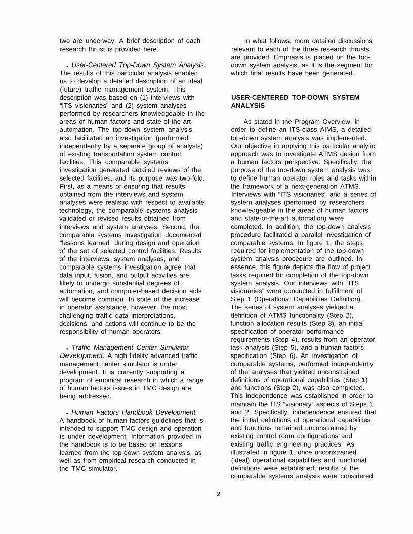
As stated in the Program Overview, inorder to define an ITS-class AIMS, a detailedtop-down system analysis was implemented.Our objective in applying this particular analyticapproach was to investigate ATMS design froma human factors perspective. Specifically, thepurpose of the top-down system analysis wasto define human operator roles and tasks withinthe framework of a next-generation ATMS.Interviews with “ITS visionaries” and a series ofsystem analyses (performed by researchersknowledgeable in the areas of human factorsand state-of-the-art automation) werecompleted. In addition, the top-down analysisprocedure facilitated a parallel investigation ofcomparable systems. In figure 1, the stepsrequired for implementation of the top-downsystem analysis procedure are outlined. Inessence, this figure depicts the flow of projecttasks required for completion of the top-downsystem analysis. Our interviews with “ITSvisionaries” were conducted in fulfillment ofStep 1 (Operational Capabilities Definition).The series of system analyses yielded adefinition of ATMS functionality (Step 2),function allocation results (Step 3), an initialspecification of operator performancerequirements (Step 4), results from an operatortask analysis (Step 5), and a human factorsspecification (Step 6). An investigation ofcomparable systems, performed independentlyof the analyses that yielded unconstraineddefinitions of operational capabilities (Step 1)and functions (Step 2), was also completed.This independence was established in order tomaintain the ITS “visionary” aspects of Steps 1and 2. Specifically, independence ensured thatthe initial definitions of operational capabilitiesand functions remained unconstrained byexisting control room configurations andexisting traffic engineering practices. Asillustrated in figure 1, once unconstrained(ideal) operational capabilities and functionaldefinitions were established, results of thecomparable systems analysis were considered
2
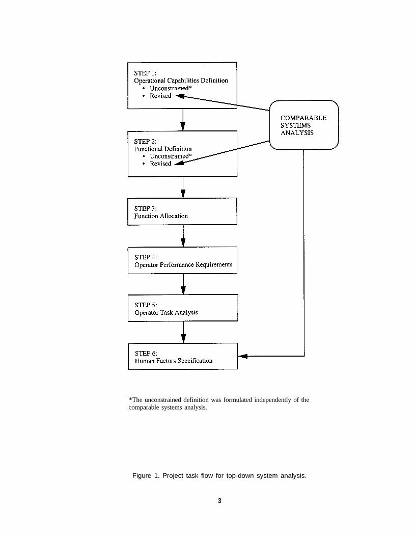
*The unconstrained definition was formulated independently of thecomparable systems analysis.
Figure 1. Project task flow for top-down system analysis.
3
and used to revise the definitions such thatthey projected realism. Finally, results of thecomparable systems analysis also served asinputs to the human factors specification (Step6). An overview of the outcomes of the top-down systems analysis procedure is offeredhere in the executive summary.
Step 1: Operational Capabilities Definition
A number of ITS experts were nominatedby their peers as “visionaries” and wereinterviewed in order to obtain a consensus ofthe objectives and capabilities of an ATMS ofthe next decade. According to a compositeview of these visionaries, the overall mission ofthe ATMS is to facilitate the safe movement ofpersons and goods, with minimal delay,throughout the roadway system network. Inorder to perform this mission, the ATMS mustpursue the following five major systemobjectives.(1)
roadway is used by emergency responders(e.g., clearing highways between a disaster siteand hospitals).
Objective 4: Contribute to the Regulation ofDemand
This objective requires motivating drivers toreschedule/reroute trips or to take alternativemodes of transportation. Regulation of demandmay be short or long term, reactive orproactive. It involves cooperative efforts withthe media and other transportation agencies.
Objective 5: Create and Maintain PublicConfidence in the ATMS
The ATMS must be perceived as providingaccurate and useful information to the public.Public confidence in the ATMS must beassessed continuously. Public relations effortsmay be conducted in order to reinforce positivepublic perception of the ATMS.
Objective 1: Maximize the Available Capacity ofArea- Wide Roadway Systems
Step 2: Functional DefinitionThe first objective is to promote the
maximum effective traffic volume (vehicles perunit of time) for existing roadways.
Objective 2: Minimize the Impact of RoadwayIncidents
Roadway incidents (accidents, stalls, fallendebris, equipment malfunctions), particularlyduring peak demand times, may have asignificant impact on travel times and create athreat to public safety. Reducing the effects ofthese incidents requires ATMS involvement ontwo fronts: reducing the likelihood of incidentsoccurring and minimizing the delays associatedwith incidents that do occur.
Objective 3: Assist in the Provision ofEmergency Services
Interaction with emergency serviceproviders may include incident detection andverification, incident notification, coordination ofresponses when multiple services are needed,and modification of system parameters toimprove speed or accuracy of an emergencyresponse. TMC support for emergencyservices is not limited to roadway incidents. Itmay be needed in any situation in which the
To further define the five objectivesresulting from completion of Step 1, a list ofrequirements for information collection,processing, storage, retrieval, and output wasproduced. These requirements were based ondiscussions (conducted with the group ofvisionaries) in which ATMS capabilities wereprojected. A set of 113 ATMS functionsnecessary to meet these requirements wasproduced.(2)
Comparable Systems Analysis
As part of the same program,approximately two dozen operational controlcenters in North America and Europe werevisited. (3) A majority of these were centers thatmonitored, controlled, or influenced automobiletraffic on urban streets or major highways.Detailed interviews were conducted withmanagers, operators, and engineers todocument system design, function allocation,operating procedures, and human factorslessons learned. Additional visits to hardwareand software vendors provided insight intoexpected evolution paths for TMC automationand design difficulties vendors sometimesexperience in working with the ITS community.
4
The comparable systems analysis wasperformed independently of the initial stages ofSteps 1 and 2. (In these initial stages,unconstrained definitions of operationalcapabilities and functionality were formulated.)This independence allowed us to maintain theITS “visionary” aspects of Steps 1 and 2.Specifically, by imposing the independencerequirement, we ensured that the initialdefinitions of operational capabilities andfunctionality remained unconstrained by existingcontrol room configurations and existing trafficengineering practices. As indicated in figure 1,once unconstrained definitions of operationalcapabilities and functionality were established,results of the comparable systems analysiswere used to revise the definitions such thatthey projected realism. As a result of thecomparable systems analysis, the followingrecommendations for revision were adopted.
l Include interfaces between the ATMS andthose traffic management systems locatedin neighboring jurisdictions.
l Include arterial but not local streets inroadway system served by the ATMS.
the
l Recognize that a metropolitan railincludes both light and heavy rail.
system
l Recognize that traffic signal cycle timeswill constrain update rates of controlalgorithms.
Automation Approaches: Three Examples
Partial automation is becoming verycommon in traffic management systems.Automation of changes in traffic signal andramp meter timing plans according to time ofday or traffic demand is already common;future signal control software will beincreasingly capable of automatic reaction.Fusion of sensor data into meaningful displaysis well advanced. Automation of VMS controland message content is the next likely TMCfunction for extensive automation. As would bepredicted from our function analysis,automation of other decisions and functions islagging.
By comparing the philosophy and operationof three relatively new ITS TMC’s, largedifferences in automation philosophy can berecognized. The three systems are equally
successful at performing their respectivemissions, even though they perform them verydifferently.
The least automated of the three is locatedin a city in the United States. Its primaryfunction is to control the city’s traffic signals inresponse to predicted and unpredicted trafficflow. A network of approximately 1000 trafficsensors and 20 closed circuit television (CCTV)cameras provides information on traffic flowand incidents. The traffic signal “timing plan”(the time devoted to each green, yellow, andred phase) is automatically controlled by thetime of day. The software also allowsautomated adaptive control according to trafficdemand, but this feature is not used. Much ofthe operator’s time is spent manually changingtiming plans to optimize flow at individualintersections. The operator also detects andreports incidents, monitors and troubleshootscomponent status, communicates with driversvia a network of VMS’s, and works closely withpolice in traffic control.
The second example, a system in Canada,monitors and controls traffic on one of thebusiest freeways in North America. A networkof loop detectors, computers, and VMS signsprovides automatic measurement of traffic flow,selection of appropriate VMS messages, anddisplay of congestion warnings to alert driversand support their rerouting decisions.Congestion levels suggestive of incidents arepresented to the operators via a graphicaldisplay. Operators using CCTV verify that anincident is present, call up an appropriate dataentry page on their computers, and enter thelocation and precise nature of the incident.Appropriate VMS incident messages areautomatically selected according to a complexset of preestablished rules and are thendisplayed on the VMS network while operatorscommunicate with other agencies to helpcoordinate any required emergency response.
The third example, implemented on majorroadways in The Netherlands, has the highestdegree of automation. The MotorwayMonitoring and Control System (MMCS) is a“lane control” system that can provide differentspeed limits or traffic restrictions dynamically foreach motorway lane. Stations consisting ofloop detectors in each lane, VMS’s for eachlane, and a networked computer are placed at
5
approximately every 500 m. When traffic isflowing freely, no restrictions are displayed, andspeed limits remain at 120 km/h. When slow orstopped traffic is detected in a lane, the stationcomputer communicates with upstream anddownstream stations. All sign changes arecoordinated and approved by a centralcomputer system. Operators can, but rarelydo, override the automated VMS system. Theprimary operator role is monitoring for MMCSmaintenance problems and closing roadwaylanes for maintenance (or as requested byother agencies). In order to composeappropriate sign patterns and transmit them toroadway outstations, operators interact with theMMCS through the central computer.Automated support systems validateoperator-composed signs. In the MMCS,operators’ incident management functions arevery limited.
Some Lessons Learned
Automation of traffic signals can createproblems when operators enter the loop. Inone center, signal timing changes occurred atset times of day. The operator frequently madeextensive manual changes only to have themerased, without warning, by an automatedchange to a new plan. In partially automatedsystems, the operator must be informed ofthose actions the automated system ispreparing to implement. Furthermore, errortraps in the software are required as a meansof checking commands that might havecatastrophic effects.
Automated detection of roadway incidentsis relatively ineffective. Numerous algorithmsbased on measured variations in traffic flowhave been developed by traffic engineers. Useof these algorithms becomes a classic signaldetection problem, where high detection ratesare associated with even higher false alarmrates. In practice, operators usually chose toignore graphical incident detection displays thatwere based on fused sensor data and choseinstead to rely on CCTV, even when relianceon CCTV caused excessive visual workload.
In several traffic management systems theultimate design goal is full automation. Whilesome existing support systems are capable ofapproaching that goal, research results suggestthat the human operator must always have a
role in the traffic management system. Severalreasons for such human participation are asfollows:
Failures in automation logic due tounforeseen circumstances (e.g., thesupport system that interpretedmaintenance activity in a closed lane asa wrong-way driver and closed theroadway).
Events that cannot be detected bysensors but that require response (e.g., theairplane crash near a freeway thatrequired road closure to all butemergency vehicles).
Support system hardware or softwaremalfunctions that require full or partialdegradation to manual mode.
One TMC implemented an automationscheme in which a support system woulddetermine the “best” pattern of changeablesigns, and the operator would review andconsent to each system-recommended change.Sign changes were so frequent (200 per hour)that operator workload was unacceptably high.Once operators recognized that the supportsystem operated at near 100 percent reliability,they modified the automation scheme to givethe support system initial response capability.Under this scheme, operators were able tomodify a pattern manually if a problem wasnoticed. Three lessons can be obtained fromthis example: (1) initial function allocationsmust be empirically validated, (2) higher thanexpected support system reliability may allowimplementation of higher levels of automation,and (3) partial task automation does notnecessarily yield decreased operator workload.
Step 3: Function Allocation
While all 113 of the ATMS functions mightpossibly be performed manually, all wereconsidered as candidates for full or partialautomation. A panel of engineers and humanfactors specialists familiar with current andanticipated automation technology examinedeach of the functions and, in a two-stepprocess, selected an appropriate level ofautomation. (4) In the first of the two steps, thepanel explored whether the function could (and
6

should) be fully automated or whether it could(and should) be performed by the operator(with no computer assistance). In the secondstep, functions that could not be assigned tofully manual or fully automated status wereassigned to one of two partial automationcategories. In each of these categories,automation level was defined in terms of theamount of autonomy given to computersystems. The four automation levels, referredto as operator roles, are summarized in table 1.
In a fully automated ATMS, every functionwould be assigned to the Executive Controllerrole. At this automation level, the operator’sprimary function is to disable or enable systemcomputers. Based on the automation analysis,however, only 29 of the 113 functions could(and should) be performed solely by anautomated system. Many of these potentiallyautomated functions involved sensing ofinformation or transmitting of previouslyformatted messages. A sample of executivecontroller functions is provided:
Table 1. Description of operator roles.
Operator Role Description Example
Direct Performer Human performs a function directlywith virtually no involvement ofmachine components. No automation.Only human senses and effectorsare used.
Operator composes messagesand manually places letters onsign. May use passive toolssuch as ladder or hand tools.
Manual Controller The human is solely responsible forclosing the control loop. Automatedsystems may sense or processinformation but the human is thedecision maker.
Operator composes messagesand types them on a keyboard.Automated system posts themon the designated sign.
Supervisory Controller Machine elements may make decisionsabout what control actions to takebased on input from the environment.The human monitors the machineperformance and may approve, revise,or reject the machine decision.
Computer selects signmessage and displays tooperator for approval.Operator may consent, editmessage, or deny permissionto display any message at all.
Executive Controller Machine components are solelyresponsible for performance of afunction. The operator enables thesystem and may turn it off if it becomesunreliable but cannot intervene in thesystem’s in-progress performance.
Operator enables messagingsystem but may not alter thecontents of a message. Theoperator may disengage themessaging system if itbecomes inaccurate or unreliable.
l Detect vehicle locations.l Detect vehicle speeds.l Receive Built-In Test (BIT) reports.l Post route advisories.l Post speed advisories.
In spite of the emphasis on increasedautomation, 40 of the 113 functions wereallocated solely to the human operator(implying no automated assistance). TheseDirect Performer functions typically involvedcommunication with outside agencies,formulation of output data, or planning. Asample of direct performer functions isprovided:
l Receive incident reports (phone).l Receive special event plans.l Determine TMC upgrade needs.l Issue request for onsite traffic
control.l Implement policy and procedures.
The remaining functions required a mixtureof human and system effort. Of thesefunctions, 28 were allocated to a human
7

Table 2. Level of operator involvement with respect to information processing stages.
Processing Stage:
Input
Processing
Response Selection
output
Level of Operator Involvement:
H H m
23 45
42 23
68 00
19 44
Mh M
02 43
10 38
16 29
00 50
decision-maker who would receive systemsupport (Manual Controller functions). Thesetypically included use of CCTV assets ordecision-making with assistance from adecision aid. A sample of manual controllerfunctions is provided:
Monitor incident clearance usingCCTV.Assess traffic congestion usingCCTV.Determine need for emergencyservices.Develop contingency plans usingdecision aids.Maintain personnel records.
The remaining 16 mixed functions wereallocated to a computer support system thatwould perform information processing anddecision-making; however, because of thecriticality and/or complexity of the decision,analysts determined that a human should bethe final authority on decision implementation.Thus, the human could approve, revise, orreject an action recommended by theautomated system. In some noncritical cases,the automated system could implement thedecision and allow the human an opportunity toalter it after implementation. Such functionswere assigned a Supervisory Controller role,and a sample of these is provided:
l Anticipate near-term traffic conditions.l Identify traffic control options.l Select best traffic control option.l Identify anomalies in traffic flow.l Determine maintenance needs.
Each of the 113 functions was defined interms of four information processing stages:input, processing, response selection, andoutput.(4) For each function (and based onfunctional requirements, human capabilities,and projected machine state-of-the-art), a levelof operator involvement was assigned to eachof the four information processing stages. Fourlevels of operator involvement werecharacterized. Each operator involvement leveland its respective notation is defined below:
l H: The human operator is solely responsible forperforming the processing stage.
l Hm: The human operator (with machineassistance) performs the processing stage.
l Mh: The machine (with human operatorassistance) performs the processing stage.
l M: The machine is solely responsible forperforming the processing stage.
Table 2 summarizes the frequency withwhich each of the four operator involvementlevels was assigned to all processing stages.Figure 2 offers a graphical representation ofthese data -- depicting the distribution ofoperator involvement levels across eachprocessing stage. Each of 452 processingstages (4 stages for each of 113 functions) wasassigned a single operator involvement level.
Not surprisingly, the percentage ofinformation stages (input and output) proposedfor full automation (M) was greater than thepercentage of response selection stages thatwas proposed for full automation. Specifically,
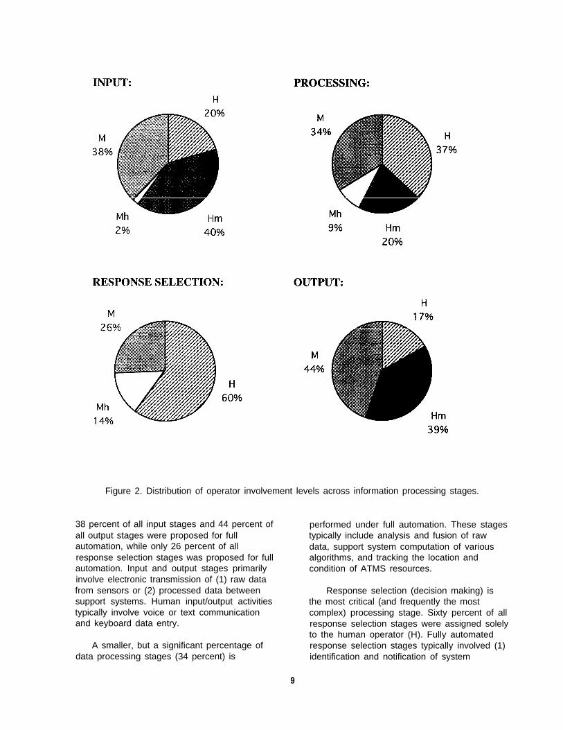
Figure 2. Distribution of operator involvement levels across information processing stages.
38 percent of all input stages and 44 percent ofall output stages were proposed for fullautomation, while only 26 percent of allresponse selection stages was proposed for fullautomation. Input and output stages primarilyinvolve electronic transmission of (1) raw datafrom sensors or (2) processed data betweensupport systems. Human input/output activitiestypically involve voice or text communicationand keyboard data entry.
A smaller, but a significant percentage ofdata processing stages (34 percent) is
performed under full automation. These stagestypically include analysis and fusion of rawdata, support system computation of variousalgorithms, and tracking the location andcondition of ATMS resources.
Response selection (decision making) isthe most critical (and frequently the mostcomplex) processing stage. Sixty percent of allresponse selection stages were assigned solelyto the human operator (H). Fully automatedresponse selection stages typically involved (1)identification and notification of system
9

malfunctions and (2) identification and deletionof corrupted data.
The purpose of these analyses was todefine human roles and tasks in an ideal next-generation ATMS. While one objectivewas to increase the level of automation, theoverall goal was to optimize the systemeffectiveness. After exploring the detailedfunctional requirements of the ATMS, thepanels of experts agreed that most of thesefunctions could not be performed optimallywithout a human in the loop.
Step 4: Operator PerformanceRequirements
Operator performance was considered interms of three types of requirements:information requirements, decision-makingrequirements, and output (response)requirements. They were considered within thecontext of four reference scenarios:
l Normal operations during rush hour traffic.l A major freeway incident during rush hour traffic.l Special event planning and traffic management
during the planned event.l A major winter storm during rush hour traffic.
These scenarios demonstrated functionalcapabilities of the ATMS and suggested therange of performance demands placed onsystem operators.
lnformation Required
An analysis of each of the four scenariossuggested that, in the course of responding toscenario events, TMC operators typicallyinteract with three types of incominginformation:
l Data to be incorporated in TMC analyses.l Analysis results.l Information employed in the operators’ conduct
of real-time traffic management.
Operator Decisions
Information received by TMC operators issubsequently processed, and one of theoutcomes of such cognitive processing activitiesis a set of decisions. In other words, operators’decisions reflect their responses to the large
amounts of data they receive. Analysis of thefour traffic scenarios revealed that operatorsmake four types of decisions:
l Accept or reject system recommendations.l Initiate activities.l Transmit information.l Assess information.
Operator Responses
Any decision reached by a TMC operator isfollowed by some form of output. Thus, eachoutput is a manifestation of an operator’scognitive processing activities. Operatoroutputs are displayed via a range of media.Scenario analyses identified five types ofoutputs operators typically manage:
l Messages.l Strategies.l Simulations.l Traffic control commands.l Data.
A subset of operator responses will involvethe distribution of traffic information to varioususers. In order to ensure the appropriatenessof such operator responses, we must “know thetraffic information users” and understand theirinformation requirements. Our taxonomyclassifies traffic information users according tofour categories:
l Institutional users.l Traffic data users.l Special service providers.l Public users.
Institutional users include city officials/planners,other agencies (e.g., school districts, publicsafety organizations), public transportationsystems, future special events hosts, andcommercial vehicle operations systems. Usersof traffic data include TMC personnel, the trafficcontrol system, and information services (e.g.,the media and traffic bulletin board services).Special service providers include incidentresponders, maintenance providers, pre-positioned assets (e.g., snow plows, salttrucks), and emergency (non-incident)responders. Public users are represented byspecial event traffic, roadway drivers, thegeneral public, public transportation operators,and commercial vehicle operators.
10

Step 5: Operator Task Analysis
The primary objectives of the operator taskanalysis are to:
l Identify the operator tasks required forsuccessful execution of each ATMS function.
l Ensure that the operator tasks associatedwith a given function satisfy the performancerequirements imposed by the operator roleassigned to that function.
l Provide an organizational framework foroperator tasks.
l Identify significant maintenance tasks.l Describe operator tasks in sufficient detail
(and context) to support the preparation of ahuman factors specification.
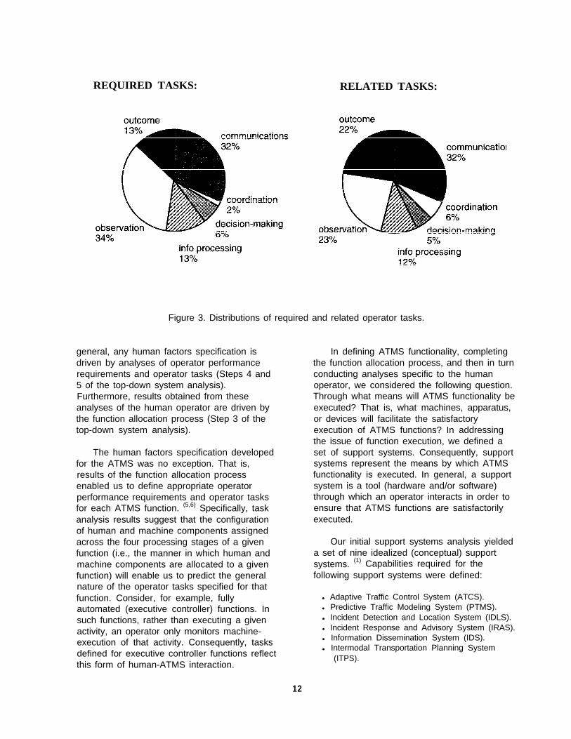
The task analysis identified a total of 363required operator tasks and 485 related tasks.Required tasks represent a core set of activitiesthe operator must perform in order forsuccessful execution of the associated function.When a given function is executed, an operatorperforms all of the required tasks associatedwith that function. Required tasks alsorepresent a high level set of activities. Thisreference to high level activities has particularmeaning when one considers the secondcategory of task type: related tasks. Inessence, related tasks support completion ofrequired (high level) tasks. A related task maybe unique to a given function, or it may appearas a related task in more than one function. Insome instances, related tasks are requiredtasks of other functions. Note that completionof all related tasks associated with a givenfunction may not be required for successfulexecution of that function. Function executionmay require completion of only a subset ofrelated tasks. Thus, the context in which afunction is executed will determine the relatedtasks that are appropriate for completion of thatfunction.
An assessment of all operator tasks(required and related) enabled us to establishsix categories of task type:
l Communications.l Coordination.l Decision making.l Information processing.l Observation.l Outcome.
Each required and related task was assigned toone of these six task type categories.Communications tasks represent thoseactivities that require TMC operators to receiveand transmit information, where this informationarrives from (and is distributed to) internal andexternal entities. Coordination tasks reflectactivities requiring TMC operators to plan,formulate strategies, and cooperate with otherindividuals or agencies that may be internal orexternal to the TMC. Decision-making taskssuggest activities that are performed as a resultof reasoning strategies or cognitive processingimplemented by the TMC operator. They areperformed once the operator recognizes that(1) the TMC is awaiting a response and (2)intervention of ongoing systems functions isnecessary. Information processing tasksrequire the operator to analyze incominginformation such that some form of reasoningstrategy is implemented. Observation tasksinvolve the TMC operator’s ability to oversee(and manage) ATMS events, where suchevents may be anticipated or unanticipated.Outcome tasks represent end products.Typically (within the context of ATMS activities),end products are analysis results. Theoperator’s performance of outcome tasksensures that these results are conveyed.
Figure 3 depicts the distributions ofrequired operator. tasks and related operatortasks, respectively.
ATMS functionality encompasses a numberof maintenance-related responsibilities. A totalof 47 required maintenance tasks and 56related maintenance tasks were identified.Note that ATMS functionality does notencompass activities directly related to therepair of components in the field. Rather theATMS focuses on (1) receiving adequate levelsof information on current conditions such thatdata reflecting system degradations andmalfunctioning components are available, (2)identifying maintenance needs in a timelymanner, (3) issuing maintenance requests tothe appropriate set of service providers, and (4)conducting maintenance training.
Step 6: Human Factors Specification
Development of a human factorsspecification represents the sixth and final stepof the top-down system analysis process. In
11
REQUIRED TASKS: RELATED TASKS:
Figure 3. Distributions of required and related operator tasks.
general, any human factors specification isdriven by analyses of operator performancerequirements and operator tasks (Steps 4 and5 of the top-down system analysis).Furthermore, results obtained from theseanalyses of the human operator are driven bythe function allocation process (Step 3 of thetop-down system analysis).
The human factors specification developedfor the ATMS was no exception. That is,results of the function allocation processenabled us to define appropriate operatorperformance requirements and operator tasksfor each ATMS function. (5,6) Specifically, taskanalysis results suggest that the configurationof human and machine components assignedacross the four processing stages of a givenfunction (i.e., the manner in which human andmachine components are allocated to a givenfunction) will enable us to predict the generalnature of the operator tasks specified for thatfunction. Consider, for example, fullyautomated (executive controller) functions. Insuch functions, rather than executing a givenactivity, an operator only monitors machine-execution of that activity. Consequently, tasksdefined for executive controller functions reflectthis form of human-ATMS interaction.
In defining ATMS functionality, completingthe function allocation process, and then in turnconducting analyses specific to the humanoperator, we considered the following question.Through what means will ATMS functionality beexecuted? That is, what machines, apparatus,or devices will facilitate the satisfactoryexecution of ATMS functions? In addressingthe issue of function execution, we defined aset of support systems. Consequently, supportsystems represent the means by which ATMSfunctionality is executed. In general, a supportsystem is a tool (hardware and/or software)through which an operator interacts in order toensure that ATMS functions are satisfactorilyexecuted.
Our initial support systems analysis yieldeda set of nine idealized (conceptual) supportsystems. (1) Capabilities required for thefollowing support systems were defined:
l Adaptive Traffic Control System (ATCS).l Predictive Traffic Modeling System (PTMS).l Incident Detection and Location System (IDLS).l Incident Response and Advisory System (IRAS).l Information Dissemination System (IDS).l Intermodal Transportation Planning System
(ITPS).
12

l Traffic Management Training System (TMTS).l Maintenance Tracking System (MTS).l Traffic Data Management System (TDMS).
Based on further analyses of operatorperformance requirements, we identified theneed for three additional support systems.Capabilities required for these support systemswere defined: (5)
l Communications Support System (CSS).l Administrative Support System (ADSS).l Maintainer Training Support System (MTSS).
The resulting 12 support systems (and thecapabilities assigned to each system) provide amechanism by which all 113 ATMS functionscan be executed. In other words, these 12support systems reflect (completely) ATMSfunctionality. Note that the capabilitiesanalyses documented in references 1 and 5have focused on idealized support systems,where the capabilities of such systems areconceptual in nature. In other words, thecapabilities assigned to a given idealizedsupport system serve as a model for thoseultimately implemented and incorporated in anoperational ATMS. A brief description of eachsupport system is presented in table 3.
In developing the ATMS human factorsspecification, we first defined the capabilitiesappropriate for each of the 12 support systemsand then established a set of human interfacerequirements for each system. (7) Each set ofinterface requirements identified and describedthe information displayed to operators via therespective support system interface, as well asinformation to be provided to the system byoperators.
Associated with the support systems is aset of hardware configuration items used byoperators for voice and text communication,information/data collection, informationprocessing, and data archiving. Some of theseconfiguration items represent stand-alonesystems (e.g., electronic mail or fax systems),while other items are incorporated into a givenmulti-purpose system, where such a system istypically computer-based. By developing thehuman factors specification such that it focuseson the support systems, we ensure that thespecification reflects all functionalcharacteristics of the ATMS, as well as the
operator performance requirements andoperator tasks defined by ATMS functionality.
TRAFFIC MANAGEMENT CENTERSIMULATOR: HUMAN FACTORS RESEARCH
Many human factors questions can only beanswered as a result of conducting empiricalresearch within the context of realistic trafficscenarios and a realistic control roomenvironment. The TMC simulator facilitates theconduct of such research. It is a real-time,interactive, reconfigurable computer networkwith the flexibility to allow testing of a variety ofoperator control and display concepts,workstation designs and control room layouts,and operator task assignments. The simulatoris capable of emulating the following types ofinputs, outputs, and support systems.
Inputs
Traffic and roadway sensors.Cellular phone dialogue.Visual CCTV sensors.Voice communication systems.Probe vehicles.Data base services.
Outputs
Intersection control devices and algorithms.Commercial radio/TV.Roadway access devices/control algorithms.Cable TV traffic channel.Variable message signs.Traffic bulletin board.Highway advisory radio.Voice output.
Support Systems
l Incident Detection and Location System.l Adaptive Traffic Control System.l Predictive Traffic Modeling System.
Note that other support systems are to besimulated as needed throughout the simulatorexperimentation program. An overview of thesimulator hardware network is provided infigure 4. The computer systems in thisconfiguration (counterclockwise from upper left)include a Video Simulation Server, fourOperator Workstations (labeled “Op WS”), five
13
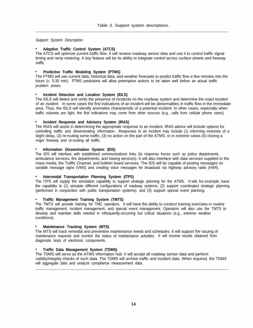
Table 3. Support system descriptions.
Support System Description
l Adaptive Traffic Control System (ATCS)The ATCS will optimize current traffic flow. It will receive roadway sensor data and use it to control traffic signaltiming and ramp metering. A key feature will be its ability to integrate control across surface streets and freewaytraffic.
l Predictive Traffic Modeling System (PTMS)The PTMS will use current data, historical data, and weather forecasts to predict traffic flow a few minutes into thefuture (c. 5-30 min). PTMS predictions will allow preemptive actions to be taken well before an actual trafficproblem arises.
l Incident Detection and Location System (IDLS)The IDLS will detect and verify the presence of incidents on the roadway system and determine the exact locationof an incident. In some cases the first indications of an incident will be abnormalities in traffic flow in the immediatearea. Thus, the IDLS will identify anomalies characteristic of a potential incident. In other cases, especially whentraffic volumes are light, the first indications may come from other sources (e.g., calls from cellular phone users).
l Incident Response and Advisory System (IRAS)The IRAS will assist in determining the appropriate response to an incident. IRAS advice will include options forcontrolling traffic and disseminating information. Responses to an incident may include (1) informing motorists of aslight delay, (2) re-routing some traffic, (3) no action on the part of the ATMS, or in extreme cases (4) closing amajor freeway and re-routing all traffic.
l Information Dissemination System (IDS)The IDS will interface with established communications links (to response forces such as police departments,ambulance services, fire departments, and towing services). It will also interface with data services supplied to themass media, the Traffic Channel, and bulletin board services. The IDS will be capable of posting messages onvariable message signs (VMS) and creating voice messages for broadcast via highway advisory radio (HAR).
l Intermodal Transportation Planning System (ITPS)The ITPS will supply the simulation capability to support strategic planning for the ATMS. It will, for example, havethe capability to (1) simulate different configurations of roadway systems, (2) support coordinated strategic planning(performed in conjunction with public transportation systems), and (3) support special event planning.
l Traffic Management Training System (TMTS)The TMTS will provide training for TMC operators. It will have the ability to conduct training exercises in routinetraffic management, incident management, and special event management. Operators will also use the TMTS todevelop and maintain skills needed in infrequently-occurring but critical situations (e.g., extreme weatherconditions).
l Maintenance Tracking System (MTS)The MTS will track remedial and preventive maintenance needs and schedules. It will support the issuing ofmaintenance requests and monitor the status of maintenance activities. It will receive results obtained fromdiagnostic tests of electronic components.
l Traffic Data Management System (TDMS)The TDMS will serve as the ATMS information hub. It will accept all roadway sensor data and performvalidity/integrity checks of such data. The TDMS will archive traffic and incident data. When required, the TDMSwill aggregate data and analyze compliance measurement data.
14
Table 3. Support system descriptions (continued).
Support System Description
l Communications Support System (CSS)The CSS will manage the two-way communications channels (1) within a single TMC and (2) between TMCoperators and entities external to the ATMS (including operators in other TMC’s, operators in other agencies, themedia, and the public at large). The CSS will support voice communications, teleconferencing, electronic mail, database links, and fax communications.
l Administrative Support System (ADSS)The ADSS will support operators’ performance of administrative duties (e.g., fiscal planning and personnelmanagement). To this end, it will include specialized software such as data basetools, graphics and wordprocessing applications, and spreadsheet software; fiscal planning information; and personnel files.
l Maintainer Training Support System (MTSS)The MTSS will provide training for maintenance providers. It will also be used to develop and maintain skills orprocedures required for the maintenance of ATMS assets (e.g., signal controllers, roadway sensors, VMS’s, probevehicle instrumentation, ATMS computers/software).
touchscreen-equipped PC’s, an ExperimenterWorkstation (labeled “Exp WS”), a Traffic ModelServer, and a Large Display Server. Throughconnections to a local area network, thesecomputer systems are able to communicate.Also included are a large-screen display withan associated switching device, several videomonitors, and a network for audiocommunications.
The Video Simulation Server is aworkstation dedicated to generating simulatedtraffic surveillance camera views. This serverincludes a “splitter” that converts the digitalsimulated video images into analog videosignals. The analog video images may bedisplayed either on standard video monitors oron Operator Workstation monitors via real-timevideo display cards installed in theworkstations.
Video signals from the Video SimulationServer enter a switching device attached to thelarge display. Other signals entering theswitching device include those for the VideoSimulation Server’s monitor, the OperatorWorkstation monitors, and the Large DisplayServer monitor. The switching device may beused to select any 1 of its 10 input signals forviewing on the large display, which ispositioned such that it can be viewed by alloperators.
The Operator Workstations provide themeans for each operator (experimental subject)to monitor and control the simulated ATMSduring experiments. The displays on theworkstation monitors provide informationregarding both traffic conditions and the statusof the ATMS infrastructure, and they allowoperators to specify actions that control theeffectors of the ATMS. Each operator’s workarea includes a touchscreen-equipped PC forsimulation of physical console controls such aspushbuttons and switches.
The Experimenter Workstation provides themeans for an experimenter to set up, control,and monitor a traffic scenario during anexperiment, as well as to monitor theperformance of the subjects.
The Large Display Server provides ameans of presenting information on the large-screen display. This server is capable ofpresenting simulated traffic video, informationfrom an operator workstation, or anindependent information display (e.g., anoverall situation display) on the large-screendisplay.
The Traffic Model Server is a workstationdedicated to running the real-time traffic model(AUTOS). Traffic flow data calculated by themodel is distributed to the Video SimulationServer, Operator Workstations, Experimenter
15
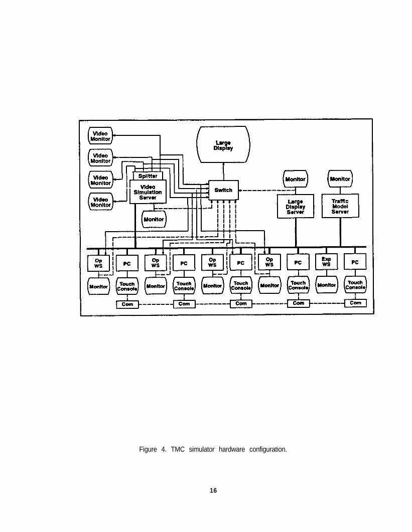
Figure 4. TMC simulator hardware configuration.
16
Workstation, and Large Display Server via thelocal area network. Commands executed atthe Operator and Experimenter Workstationsmodify parameters of the traffic model andthereby affect the traffic simulation.
The final simulator component is the audiocommunications network. This componentsupports communications between operatorsand simulated outside agencies such as police,emergency dispatch, and other TMC’s. Theexperimenter and members of theexperimenter’s staff assume the roles of outsideagency personnel. An Integrated ServicesDigital Network (ISDN) network using a Teleosnetwork hub and PC-based ISDN cards is usedfor audio communications.
A comprehensive program of humanfactors research has been designed to helpprepare design guidelines for future ITSTMC’s. (8) Teams of subjects are trained on theuse of the TMC Simulator equipment until theirperformance stabilizes (generally 8 to 12 h).They then perform realistic traffic managementfunctions, reacting to preset roadway conditionsthat involve combinations of traffic extremes,weather, and/or incidents.
Initial experiments are focusing onhuman factors issues relevant to the designand control (manual and automated) of existingsystems (e.g., CCTV systems, graphicsdisplays). Later experiments will addressdesign issues relevant to team coordination,workload, training, and issues critical to thedesign and introduction of automation andcomputer-based support systems. Thisresearch will address available automation andsupport technology for the early ITS (current)period and the mature ITS (post-2000 AD)period. It will also address TMC’s that aredesigned “from scratch” and subsequentlyimplemented as an integrated system, as wellas the more common design approach in whichupgrades are performed in a piecemealfashion, as budget increments allow.
HUMAN FACTORS HANDBOOKDEVELOPMENT
development of a human factors designhandbook. The handbook is intended tosupport TMC design and operation.Information provided in the handbook is to bebased on lessons learned from the top-downsystem analysis, as well as from empiricalresearch conducted in the TMC simulator.
Two editions of the handbook will beproduced. The first edition will incorporateexisting human factors guidelines (that arerelevant to the TMC environment), as well asapplicable design information documented inthe research literature. The second editionhandbook will incorporate results obtained fromthe conduct of TMC simulator experiments.
SOME GENERAL COMMENTS ONTOP-DOWN SYSTEM ANALYSIS AND THEATMS
The technical report to follow describes themethods and philosophy underlying theuser-centered top-down system analysis of anideal (but realistic) ATMS. Conducting thecomparable systems analysis independently ofthe initial phases of Step 1 (derivation of anunconstrained definition of operationalcapabilities) and Step 2 (derivation of anunconstrained definition of functionality)enabled us to maintain the ITS “visionary”aspects of these two system analysiscomponents. At the same time, data from thecomparable systems analysis affirmed that ourresultant operational capabilities definition andfunctional requirements were realistic.
Note that each ATMS is unique, whereobjectives, priorities, funding, experience, andproblems vary across systems. Such ananalysis for a system whose primaryresponsibility is special event management, forexample, will most likely generate results thatare different from those generated by atop-down analysis for a system whose primaryresponsibility is the management of trafficcongestion. While the methods and analysisphilosophies offered in this report may beapplied broadly, analysis results represent oneexample, rather than a universal solution.
The third and final feature of thisresearch program encompasses the
17

REFERENCES
1. Folds, D. J., Stocks, D. R., 5. Mitta, D. A., Najjar, L. J., Folds, D. J., andEngler, H. F., and Parsonson, P. A. Courtney, T. K. (1994). Human Operator(1993). Operational Capabilities of an Performance Requirements in anIVHS-Level Advanced Traffic IVHS-Level Advanced TrafficManagement System, Working Paper Management System, Working PaperA-9309-A.2, Unpublished, Federal A-9309-E.1, Unpublished, FederalHighway Administration, Washington, DC, Highway Administration, Washington, DCAugust 1993. February 1994.
2. Folds, D. J., Brooks, J. L., Stocks, D. R.,Fain, W. B., Courtney, T. K., andBlankenship, S. M. (1993). FunctionalDefinition of an Ideal Traffic ManagementSystem, Working Paper A-9309-B.1,Unpublished, Federal HighwayAdministration, Washington, DC, June1993.
7.3. Kelly, M. J., Gerth, J. M., and Whaley, C.
J. (1994). Comparable SystemsAnalysis: Design and Operation ofAdvanced Control Centers, PublicationNo. FHWA-RD-94-147, Federal HighwayAdministration, Washington, DC.
6. Mitta, D. A., Folds, D. J., Beers, T. M.,Najjar, L. J., and Coon, V. E. (1994).Human Operator Tasks in an IVHS-LevelAdvanced Traffic Management System,Working Paper A-9309-G.1, Unpublished,Federal Highway Adminstration,Washington, DC, July 1994.
4. Folds, D. J., Fisk, A. D., Williams, B. D.,Doss, J. E., Mitta, D. A., Fain, W. B.,Heller, A. C., and Stocks, D. R. (1993).Operator Roles and Automated Functionsin an IVHS-Level Advanced TrafficManagement System, Working PaperA-9309-D.1, Unpublished, FederalHighway Administration, Washington, DC,November 1993.
Kelly, M. J., Najjar, L. J., Mitta, D. A., andFolds, D. J. (1994). Human InterfaceRequirements and Human FactorsSpecification for an Ideal AdvancedTraffic Management Center, DraftWorking Paper A-9309-H.1, Unpublished,Federal Highway Administration,Washington, DC, July 1994.
8. Folds, D. J., Kelly, M. J., Gerth, J. M.,Mitta, D. A., Whaley, C. J., Fain, W. B.,Heller, A. C., Fisk, A. D., Najjar, L. J., andStocks, D. R. (1994). Human FactorsExperimentation Plan for the TrafficManagement Center Simulator, WorkingPaper A-9309-K.1, Unpublished, FederalHighway Administration, Washington, DC,February 1994.
18
SECTION 1.BACKGROUND AND INTRODUCTION
Roadway traffic congestion is a costlyworld-wide problem. In the United States, costsassociated with congestion-caused accidents,loss of resources, lost time, and added pollutionhave been estimated at $170 billion per year. (1)
One partial solution is to bring high technologyto traffic management through the widespreaduse of smart cars and smart highways of theintelligent vehicle-highway system (IVHS).Estimates indicate that by the year 2000, morethan 200 United States cities will have adoptedsome elements of IVHS technology. Similartechnology growth is evident in Europe and onthe Pacific Rim. Receiving major emphasis isthe IVHS advanced traffic management system(ATMS). The ATMS is designed to coordinateand facilitate the safe movement of individualsand goods, with minimal delay, throughout aroadway network.
The Typical Traffic Management System
Current traffic management systems (TMS)are beginning to integrate IVHS technology withexisting traffic sensing and control resources.Emerging ATMS’s incorporate a complexnetwork of traffic sensors, informationprocessing and decision aiding systems, andeffector systems. Traffic sensors are placed atcritical roadway locations and typically consistof two types of components: loop defectors andclosed circuit television (CCTV) cameras. Loopdetectors (wire coils embedded in roadwaypavement) detect and signal the passage offerrous metal in vehicles. Effector systemsmost frequently include intersection trafficsignals, freeway ramp meters, and variablemessage signs (VMS’s) that may warn driversof traffic problems and suggest alternate routes.Within the TMS, computers (1) fuse data from,perhaps, thousands of loop detectors, (2)display sensor and CCTV information (tosupport the operators’ situation awareness),and (3) in some cases make and carry outdecisions.
Traditionally, the TMS’s data gathering,decision making, and communication functionshave been performed manually. Operatorknowledge of traffic situations were incomplete,and the available repertoire of response
capabilities was limited. Thus, only a limitedrange of traffic management services could beprovided.
Innovative technologies in data sensing,data fusion, communication, automation, anddecision support systems are expandinginformation flow and promoting a broad rangeof traffic management options. With theexpansion of computer technology, many newand traditional functions can be fully or partiallyautomated. The most apparent resultsstemming from advanced technologies are anincrease in (1) the number of trafficmanagement services that can be provided and(2) the efficiency with which traffic can becontrolled.
Given recent advancements in computingand communication technologies, some existingcenters have established a design goal of fullautomation, i.e., a lights-out (completelyautomated) ATMS. Yet many attempts atautomating tasks currently performed manuallyhave been clumsy and not entirely successful.Other attempts have automated taskssuccessfully by reducing their complexities orby distributing parts of given tasks to otheragencies. (2) For the near future, full serviceATMS’s will continue as hybrid automatedsystems, where most automation will bedesigned to support human operators, ratherthan rep/ace them.
USER-CENTERED DESIGN
A less visible result of recent technologyadvancements is a substantial change inoperator jobs. The broader range of servicesto be provided by the ATMS requires operatorsto demonstrate a broader range of expertiseand skills. Operators will be expected tointeract with complex, partially automatedsystems with which they have little experience.
Designers and manufacturers of complex,programmable, and automated equipment havefound that users are often befuddled by eventhe simplest of tasks. (3) Effective utilization andperformance of a complex system are
19

dependent upon system design and theinterface between system hardware and theend user.
To ensure usability of new systems,designers should center the design process onthe human factors of the ultimate system user(i.e., the needs, expectations, capabilities, andlimitations of the end user). In a user-centereddesign process, emphasis is placed on the userduring the initial stages of the process. Userrequirements are represented in the systemspecification. Users’ needs are identified,analyzed, and reanalyzed. Every aspect of thesystem, from its overall purpose to the mostseemingly trivial aspect of the user interface, iscarefully designed to satisfy user needs
ofThe user-centered design p
four basic elements: (4)
l Early focus on users.l Integrated system design.l Continual user testing.l Iterative design.
rocess consists
An early focus on users places designers indirect contact with a representative set of users.Such contact can be achieved throughinterviews, surveys, and users’ activeparticipation in the design process. Integratedsystem design implies that all elements withwhich the user will have contact (user interface,on-line help, training, and documentation) aredesigned in parallel. System usability andacceptability are continually evaluated throughthe use of simulations, mockups, andprototypes that, through testing, are capable ofmeasuring user performance and reactions. Aniterative design philosophy ensures that designrevisions, as well as repetition of the initialthree elements (early focus on users, integratedsystem design, continual user testing), areimplemented.
Design of a complex human-machinesystem (such as the ATMS) from auser-centered perspective must go far beyondassessment of individual display and controlcomponents and arrangement of them in agiven workstation. Human factors inputs to thedesign process should have a significant impacton high-level design philosophy, particularly inestablishing the rationale that underlies the
allocation of roles to the system’s human andmachine components.
As a crucial part of TMC configuration tradestudies, human operator roles must be defined.Specifically, each system function may beallocated to the human operator, an automatedsystem, or some combination of the two.Function allocation becomes the basis for adetailed specification of expectations for (1)TMC hardware and software capabilities and(2) operator-system interaction activities. Adetailed operator task analysis enhances thedesign, the selection and training of operators,and the development of on-line help facilitiesand written user documentation.
As TMC structure and architecture areclarified in this process, designers can begin todefine the operators’ interfaces to (1)configuration items, (2) one another, and (3)outside agencies. Whenever operators areavailable, their expertise should be used toassist in refining a system design.
Applying the user-centered design processis more convenient during systematic systemupgrades than during initial design. Duringupgrade planning, a cadre of operators whohave experience with the roadway network,operating philosophies, and systemcapabilities/constraints is available.User-centered design was effectively applied inone remodeled European control center. Byconducting operator interviews and consultingprocedures manuals and job aids, a designconsultant performed requirements, function,and task analyses. Based on analysis results,three candidate mockups of the new controlroom were prepared. Operators selected theirfavorite and then worked with the designer torefine the design. This process produced avery functional center. (2)
User-Centered Top-Down System AnalysisMethods
Top-down system analysis (TDSA) is aniterative process by which the operations of asystem under design are described inever-increasing levels of detail. Each analysisstep defines (in greater detail) the resultsgenerated by the previous step. When appliedto the ATMS environment such an analysisrepresents a comprehensive depiction of the
20
flow, processing, fusion, and use of information.Technology is not considered until systemcapability requirements, operator tasks, andhuman interface requirements have beenanalyzed. Decisions concerning specificinformation channels (e.g., telephone versushardcopy) or allocations of functions to specificmachines are reserved for the later stages ofanalysis.
Each step of the TDSA explores anddocuments details of the results obtained at theprevious analysis level. In turn, resultsobtained at a given analysis level are subject toelaboration in subsequent steps.
As part of the user-centered developmentprocess in this IVHS research program, adetailed TDSA for the ATMS was conductedand documented. Figure 3 defines theprogression of steps associated with the TDSAprocess. A brief overview of each step isprovided in the remainder of this section. Moredetailed discussions of these steps, and theresults we obtained upon their implementation,are presented in the subsequent sections ofthis report.
IMPLEMENTATION OF USER-CENTEREDTDSA
Step 1: Operational Capabilities Definition
The first step of the TDSA was to derive acomprehensive statement concerning theATMS's mission and objectives. Consequently,we determined that the global mission of theATMS is to coordinate and facilitate the safemovement of individuals and goods, withminimal delay, throughout a roadway system.In order to achieve this mission, the ATMSmust pursue the following objectives: (5)
l Maximize the available capacity ofarea-wide roadway systems.
l Minimize the impact of roadwayincidents.
l Assist in the provision of emergencyservices.
l Contribute to the regulation of demandl Create and maintain public confidence
the ATMS.in
Section 2 of this report defines these objectivesin greater detail.
Step 2: Functional Definition
Performance requirements specified by thefive system objectives were developed.Functionality associated with theserequirements was defined. A detailed functionanalysis produced 113 ATMS functions. (6)Section 2 of this report documents thefunctionality derivation process.
While the initial derivation of (ideal) systemobjectives and functionality represented noreal-world constraints, we recognized theimportance of a certain degree of realism.Realistic system objectives and functionality, forexample, could not incorporate technologiesthat would be unavailable in the next decade.Consequently, a comparable systems analysisinvestigated existing and anticipated ATMS’sand the lessons learned in the implementationand operation of such systems. Based on thefindings of this analysis, our initial, visionarydescriptions of the ideal ATMS and itsfunctionality were slightly revised.
Comparable Systems Analysis
The comparable systems analysis wasperformed independently of the initial stages ofSteps 1 and 2. (During these initial stages,unconstrained definitions of operationalcapabilities and functionality were developed.)This independence allowed us to maintain theIVHS “visionary” aspects of Steps 1 and 2.Specifically, by imposing the independencerequirement, we ensured that the initialdefinitions of operational capabilities andfunctionality remained unconstrained by existingcontrol room configurations and existing trafficengineering practices. As indicated in figure 3,once unconstrained definitions of operationalcapabilities and functionality were established,results of the comparable systems analysiswere used to revise the definitions such thatthey projected realism. As a result of thecomparable systems analysis, the followingrecommendations for revision were adopted.
21

*The unconstrained definition was formulated independently of thecomparable systems analysis.
Figure 3. Top-down system analysis procedure.
22

l Include interfaces between the ATMS andthose traffic management systems locatedin neighboring jurisdictions.
l Remove local streets from the roadwaysystem served by the ATMS.
l Recognize that a metropolitan rail systemincludes both light and heavy rail.
l Recognize that traffic signal cycle timeswill constrain update rates of controlalgorithms.
Revisions to the operational capabilitiesdefinition and functional requirements arediscussed in greater detail in section 2.
The comparable systems analysis exploredexisting ATMS technology and near-termenhancements that will be available.Approximately 20 advanced operation controlcenters in the United States, Canada, andEurope, along with developers and vendors ofhardware and software systems for the trafficmanagement market, were visited. (2) Whilemost of the centers represented advancedtraffic control and traffic management centers,several represented other types of advancedcontrol centers (i.e., air traffic control, aircombat training control, public transit operationsmanagement, and fleet operations centers fortrucking and air cargo.)
During site visits, control room design andoperations were observed. Training andoperational documentation was examined.Additionally, structured interviews wereconducted with center managers and operators.Special emphasis was placed on obtaininginformation related to experience gained andlessons learned for the following issues:
l
l
l
l
l
l
l
l
l
l
l
Analysis of a timeline of activity.Demographic information.Minimum qualifications for TMC managers.Minimum qualifications for TMC operators.TMC layout (including recent or plannedchanges).TMC configuration items (including recentor planned changes)Interjurisdictional coordination.Data archiving.Human factors of system documentation.Human factors of job handbooks andprocedures manuals.Human factors aspects of control room,
layout, and furniture.Human factors of operator displays.Human factors of operator controls.Allocation of manager and operatoractivities between tasks.Sources of input information.Applications of automation.Human factors aspects ofcommunication systems.Maintenance responsibilities.TMC staffing.Large-screen displays.Console video monitors.TMC design process (including contractors andmethods).
l TMC environmental factors.l Operators’ musculoskeletal complaints.
At each site, still-photographs were taken.Copies of training documentation, procedures,standard forms, and checklists were alsoobtained, and their roles in operator tasks weredocumented. Where possible, operators wereobserved during normal operating conditions.Descriptions of operator tasks, operator inputsand responses, roadway event history, and anysignificant successful (or awkward) applicationsof display, control, or automation technologieswere recorded. At each site, state-of-the-artand future plans were documented. Humanfactors lessons learned in the design andoperation were recorded.
Step 3: Function Allocation
Early function allocation approachesassigned a given function to either an operatoror machine component, according to thecomponent that could best perform the function.This approach is far too simplistic to apply tocurrent complex systems: it does not addressthose situations in which functions are executedjointly by the two components. Newapproaches to function allocation define thelevel of operator involvement. A long-term goalof some traffic management systems is totalautomation; the goal of others is to remainoperator-intensive. Each philosophy hassignificant design implications for the ATMS.
Operator role theory provides a frameworkunder which human factors engineers candefine operator responsibilities and machineperformance requirements. (7) Inhybrid-automated systems, the operator’s rolein a given function is considered to represent a
23

point on a continuum that ranges fromcomplete manual performance to completeautomation.
While all 113 ATMS functions mightpossibly be performed manually, all wereconsidered as candidates for full or partialautomation. A team of engineers and humanfactors specialists familiar with current andanticipated automation technology examinedeach of the functions and, in a two-stepprocess, selected an appropriate level ofautomation (operator role) for each function. (7)
In the first of the two steps, the team exploredwhether the function could (and should) be fullyautomated or whether it could (and should) beperformed solely by the operator (with nocomputer assistance). In the second step,functions that could not be assigned to fullymanual or fully automated status were assignedto one of two partial automation categories. Ineach of these categories, operator role wasdefined in terms of the amount of autonomygiven to computer systems.
Each function was defined in terms of fourstages of information processing: input,processing, response selection, and output.The analysts assigned each stage to one offour levels of operator involvement (solelyoperator, primarily operator, primarily machine,solely machine). This assignment was basedon the anticipated state of near-termautomation technology. The bias was towardassigning the highest practical level ofautomation.
The assignments of (1) operator roles toATMS functions and (2) operator involvementlevels to information processing stages aredescribed in section 3 of this report.
Step 4: Operator PerformanceRequirements
Once operator roles were assigned to allfunctions, specific implications for operatorperformance were derived. (8) Operators’information requirements, informationprocessing/decision-making requirements, andresponse requirements were specified. Resultsof these analyses are presented in section 4.
Step 5: Operator Task Analysis
An operator task analysis was conducted.This analysis was based upon results of thefunction allocation process (i.e., assigning anoperator role (level of automation) to eachfunction and assigning levels of operatorinvolvement to that function’s informationprocessing stages), as well as operatorperformance requirements. (9) A set of operatortasks was defined for each function. Taskswere defined in accordance with the operatorrole designation. Task analysis results arepresented in section 5.
Step 6: Human Factors Specification
The operator task analysis provided a basisfor developing a human factors specification forthe ATMS and its respective configuration itemsand functional areas. Many operator tasks, forexample, assume a configuration item and thisitem’s links to other functional areas. Indeveloping a human factors specification, wegrouped tasks according to a correspondingconfiguration item (e.g., all tasks requiringtelephone communications were groupedtogether) or a functional area (e.g., all tasksperformed with electronic mail system weregrouped together). This task reorganizationdefines the operator activities that must besupported by a given configuration item orfunctional area. In other words, thereorganization summarizes performancerequirements for configuration items (orfunctional areas) and provides preliminaryinterface requirements for configuration itemsand functional areas. (10) Discussion related todevelopment of the human factors specificationis presented in section 6.
Decision-making tasks were not assignedto a configuration item, as they reflected humancognitive activities. For some tasks,assignment to a unique configuration item wasinappropriate, as multiple configuration itemswould serve equally well (e.g., datatransmission via facsimile versus datatransmission via electronic mail). Under theseconditions, the task was assigned to allappropriate configuration items. In somecases, analysts assigned tasks to aconfiguration item according to professionaljudgment, noting that a certain degree ofambiguity existed. For those tasks not
24

obviously associated with a configuration itemor functional area, we suggest additionalresearch to assist in selection of theappropriate item/area.
The performance of many ATMS functions(and their respective operator tasks) will beassisted by automated or hybrid-automatedsupport systems. Such support systemsrepresent the means by which ATMSfunctionality is executed. Each support system
will consist of an operator interface throughwhich the operator can enable or disable thesystem, monitor system activities, accept orreject system recommendations, modify systemoutput, or actively control the system. For eachsupport system, information displayed tooperators via the support system interface, aswell as information to be provided to thesystem by operators, was specified. Theserequirements are discussed in section 6.
25

SECTION 2.OPERATIONAL CAPABILITIES DEFINITION AND FUNCTIONAL DEFINITION
INTRODUCTION
This section begins to document thetop-down system analysis used to describe theoperations of an advanced traffic managementsystem (ATMS). Specifically, the initial stagesof this analysis procedure (determiningoperational capabilities and deriving ATMSfunctionality) are described. In establishingoperational capabilities, we consider the ATMSmission, its objectives, and its performancerequirements. ATMS functionality is definedsuch that ATMS objectives and performancerequirements are satisfied. Additionally,analysis results are presented.
In what follows, the methodology employedin conducting the analysis is described.Initially, the approach focused on an idealizedATMS, that is, a system unconstrained byexisting practices, funding uncertainties, politicalenvironments, or the performance of advancedtechnologies. System objectives, performancerequirements, and functional definitionformulated for the unconstrained environmentwere ultimately revised to reflect actual andanticipated constraints. (These revisions areincorporated in the functional definitionpresented later in this section.) Methods for (1)collecting and analyzing relevant data, (2)formulating functionality for the unconstrainedenvironment, and (3) revising this idealizedfunctionality are offered.
Finally, results obtained fromimplementation of the methodology arepresented. We begin with a general missionstatement and a set of system objectives.System performance requirements that identifyoutput, input, throughput, and supportrequirements are subsequently specified. Notethat each system objective is achieved onlythrough successful execution of ATMSfunctionality. In other words, system objectivesdrive the functional specification.Consequently, the functionality required byeach objective is identified, and a completeATMS functional definition is offered.
METHOD: OPERATIONAL CAPABILITIESDEFINITION AND FUNCTIONAL DEFINITION
A survey of leading traffic management andtraffic engineering experts in the United Stateswas conducted. Each expert participated in astructured interview and presented his vision ofideal ATMS performance (projected 5 to 10years in the future). Edited transcripts of eachinterview were evaluated by four analystsworking independently. Results generated bythese analysts were combined into a compositeview of ATMS capabilities. System objectivesand performance requirements were derivedfrom this composite view.
The analysts then examined selecteddocuments (bibliography) in order to extractprojections on IVHS technology maturation fora period of 20 years into the future. Theseprojections enabled the analysts to extend theexisting composite view of ATMS capabilities toa view representative of mature IVHSenvironments.
Participants
Thirteen individuals participated in thepersonal interview/survey study. Theseparticipants, experts in traffic management andtraffic engineering, represented privatecompanies, as well as a number of local, State,and Federal agencies. (11) A list of candidateexperts was formed. Names appearing on thislist were suggested by the Federal HighwayAdministration (FHWA), Georgia Techpersonnel, and supporting contractors for theFHWA and Georgia Tech. The candidateexperts were contacted, and personalinterviews were arranged with as many of theseexperts as possible. Eleven personalinterviews were conducted. Two individuals,unable to meet for their scheduled interviewsessions, provided colleagues to serve assubstitutes. Two additional individuals wereunable to schedule appointments, and theyvolunteered to provide written responses to theinterview questions.
Participants were approximately evenlydivided across local (city) governments,
27
State/Federal government, and private industry.(Four participants represented localgovernments, and four representedState/Federal government. The remaining fiveparticipants represented private industry.)Within local government, State/Federalgovernment, and private industry categories,participants’ professional responsibilities werefocused either on traffic engineering/management activities or research anddevelopment. All four participants from thelocal government sector performed trafficengineering or traffic management activities.On the other hand, four of the five participantsfrom the private industry sector were involvedin research and development efforts, while onlyone of these five performed traffic engineering/management activities. This particulardistribution reflects the tendency of trafficengineering personnel within local governmentsto be directly involved in traffic managementand for traffic engineers within private industryto focus on research and development efforts.Participants from the State/Federal governmentsector were equally divided across the trafficengineering/management and research anddevelopment categories.
Survey Procedure
A preliminary statement of survey contentwas drafted and presented at the programkickoff meeting. Revisions were madeaccording to comments received at thismeeting. A draft of the survey was developed,and a pilot test in which one of the surveyparticipants responded to the draft wasconducted. Based on feedback obtained as aresult of the pilot test, minor proceduralrevisions were made. A blank survey form isincluded in appendix A.
Personal interviews were conducted by atwo-person team, where one team memberposed the questions appearing on the surveyform, and the other recorded responses inwriting. (No tape recording was made.)Interviews were conducted in participants’offices. A letter of introduction from the FHWAwas presented. This letter identified the FHWAas a research sponsor and described thegeneral nature of the program. An introduction
to the survey was reviewed with eachparticipant. It discussed relevant backgroundmaterial and the purpose of the interview.(Refer to item one of the blank survey form inappendix A). Any questions posed by theparticipant were answered.
Shortly after conclusion of the interview, theinterviewers reviewed their handwritten notesand prepared an edited transcript of theinterview for use in an analysis of content.Editorial changes included the rewording of anyresponses that might reveal the participant’sidentity, clarification of pronoun referents, theaddition of proper punctuation, and the additionof explanatory material (in instances where theliteral transcript did not convey the meaning asunderstood by the interviewers). All editorialchanges (excluding punctuation) were enclosedin square brackets.
For the two individuals who volunteered tocomplete the survey in writing, the followingprocedure was employed. Survey content wasdiscussed by telephone, and a copy of thesurvey form was sent to the respondent. Therespondent prepared handwritten responses onthe survey form and returned it to the interviewteam.
Content Analysis Procedure
Four analysts with backgrounds in physics,electrical engineering, math and computerscience, and engineering psychology wereselected to perform a content analysis ofinterview transcripts. The analysts wereinstructed to work independently. Analysesbegan once the first four interviews had beenconducted. A seven-step procedure wasfollowed.
Step I: Initial Reading and Summarization
As a means of controlling for order effects,each analyst read the first four transcripts in aunique order. The analyst read a transcript andprepared a brief written summary. Thesummary described the major themes andareas of emphasis in the interview andidentified those aspects of the interview thatseemed prominent or distinctive. This step wasrepeated for each of the first four interviews.
28

Step 2: Paired Comparison of Surveys Step 5: Updating of Scenarios
For the first four surveys, the analysts As analysts read and compared additionalcompared survey pairs. (Six survey pairs were interviews, they updated scenario descriptionspossible, and analysts compared all possible and significant variants. For the purposes ofsurvey pairs.) In the comparisons, the analysts improving the illustration of ideal ATMSidentified areas of agreement, disagreement, performance objectives, analysts wereand non-overlap. The comparisons were sanctioned to make fundamental changes tosummarized in writing. any scenario.
‘Step 3: Description of Prominent Vision andVariants
Based on the data obtained from the firstfour interviews, the analysts prepared apreliminary description of the most prominentvision of the ideal ATMS. Subsequently, theyconstructed four scenarios reflecting this vision,where thescenarios depicted in the surveyform served as a basis for development.(Scenarios 1 and 2 of the survey werecombined into a single scenario.) Indocumenting the prominent ATMS vision,analysts constructed four scenariosencompassing a broad range of events forwhich the ATMS must be responsible. Thesescenarios depict the following conditions:
l
l
Normal operations during rush hour traffic.Major freeway incident during rush hourtraffic.
l Super Bowl planning and trafficmanagement.
l Major winter storm during rush hour traffic.
For the purpose of example, the secondscenario (major freeway incident during rushhour traffic) is provided in appendix B. Theanalysts also described variants (i.e., minorityopinions appearing in the survey data thatdeserved consideration).
Step 4: Reading and Processing of AdditionalInterviews
As additional interviews were conducted,respective transcripts were made available tothe analysts (again, in varying orderingschemes). Analysts repeated Step 1 for eachinterview. Step 2 was also repeated; however,analysts did not conduct all possible pairedcomparisons. Rather, they selected fourprevious interviews (offering a broad range ofcontrasts) and compared newly acquiredtranscripts against these four.
Step 6: Conduct of Joint Working Session
Once all participants were surveyed,analysts and interviewers assembled for a jointworking session in which differences ofinterpretation were discussed. Each analystalso shared suggestions for scenarioenhancements. Responses obtained from thetwo individuals providing written surveyresponses were distributed. The analysts didnot summarize/compare data from these twoparticipants (Steps 1 and 2), but they were freeto incorporate any of these participants’ ideas inthe scenario revisions. (See Step 7.)
Step 7: Derivation of Detailed Timelines
After conclusion of the joint workingsession, analysts returned to Step 5 andrevised the scenarios (1) according to theopinions and suggestions of the other analystsand (2) after considering the ideas of the twoexperts who provided written responses. Foreach scenario, the analysts produced adetailed timeline of events. These timelineswere defined according to time-basedperformance goals specified by the experts.These timelines included descriptions of events“in the field” as well as ATMS actions.
Product of the Content Analysis
Analysts’ results were combined into anoverall ATMS description. System objectivesand performance requirements were derivedfrom this overall description. Five scenarioswere developed to illustrate the performancecapabilities of the ATMS.
Extrapolation to a Mature IVHS Environment
The product of the content analysisreflected experts’ assumptions and expectationswith respect to human operator roles in a futureATMS (i.e., an ATMS available 5 to 10 years in
29
the future). The 5- to 10-year time frame alsoproduced a fairly conservative view of theavailability of IVHS technologies.
In order to extend the vision of ATMScapabilities to a mature IVHS environment, theanalysts reviewed relevant sections of selecteddocuments (bibliography). Each analystprovided an assessment of the impact ofIVHS-related technology development on ATMSperformance requirements and capabilities.ATMS performance requirements were updatedto reflect these assessments.
Derivation of Functional Definition
ATMS objectives are the basis of functionalrequirements. For each objective,corresponding functions are derived from (1)the outputs required to satisfy the objective and(2) the input, throughput, and support functionsrequired to generate those outputs. Outputfunctions control traffic (directly or indirectly).They disseminate information, control electronicdevices, and issue requests. Input functionsreceive information: sensor data, reports fromexternal sources, and information requests.Throughput functions are internal to the ATMSand use available information to properly selectoutputs. They process and fuse data, makepredictions, assess current conditions, andmake decisions. Support functions create andmaintain the capabilities of other functions.They are responsible for storing and retrievinginformation, training operators, planning,performing administrative duties, andcoordinating with other agencies.
Revisions: Objectives, PerformanceRequirements, and Functional Definition
The initial formulation of ATMS objectives,performance requirements, and functionaldefinition was intentionally developed withoutregard for real-world constraints, existingpractices in traffic engineering, or specificproposals for the design of an ATMS or itssubsystems. Consequently, the systemanalysis procedure required subsequentconsideration of these constraints, practices,and proposals. Upon consideration of suchconstraints, analysts revised idealizedobjectives and performance requirementsdeveloped initially.
Three sources of information were used tomodify the objectives and performancerequirements of the ATMS:
Preliminary findings the comparable systemsanalysis. (12)
Recommendations from the primecontractor of the Support Systems Contract(SSC). The SSC is a parallel contract inwhich plans for ATMS support systems arebeing developed).
Consideration of current practices inconventional traffic engineering. (Manyof these practices will continue well intothe IVHS era.) Conventional traffic signals,for example, will continue to be used forintersection control in the near-term andmid-term of IVHS deployment. An ATMSintroduced at the inception of IVHSdeployment must exert control overconventional and advanced systems.
The specific recommendations adoptedduring the process of revising ATMS objectives,system performance requirements, and theATMS functional definitions are presented inthe following paragraphs.
Recommendations
Include interfaces between the ATMS andthose traffic management systems located inneighboring jurisdictions. Initially, the ATMSwas conceived to exercise complete jurisdictionover traffic management for a metropolitanarea. Although such jurisdiction may beachieved in some areas, political considerationswill cause some ATMS boundaries tocorrespond to municipal, county, or State lines.In some metropolitan areas, interactionsbetween several ATMS’s may be required. Inthis manner, the management of traffic flow iscoordinated, where cooperation among thisgroup of ATMS’s is essential. (The sources forthis change were the comparable systemsanalysis and the SSC.)
Include a capability to receive policy andbudgetary directives from governing agencies.Initially, the ATMS was described as anindependent agency -- independent of fundingconstraints and free to establish its own policiesas needed in fulfilling objectives. A real-worldATMS, however, must operate according to a
30
budget established by a governing agency, andthe ATMS must comply with policy directivesissued by that agency. (The source for thischange was the SSC.)
Remove local streets from the roadwaysystem served by the ATMS. The originaldescription included no specification regardingan exclusion of certain roadway segments fromsystem sensor and control coverage. Bydefault, all segments were covered. In therevised description of the ATMS requirementsand capabilities, service is limited to tollways,freeways, major arterials, minor arterials, andcollector streets. (The source of this changewas consideration of existing practices.)
Include a capability to collect data forelectronic toll and tax. Although the ATMS isnot a toll or tax-collecting agency, the use ofcertain roadway segments is subject to thepayment of tolls or taxes. In some areas (andas a means of regulating demand), the chargefor using certain segments of the roadwaysystem may be based, in part, uponcongestion. Automatic Vehicle Identification(AVI) systems would provide a means forcollecting tolls such that properly-equippedvehicles would not be required to slow or stop.Given its inherent requirements to monitor theroadway system and minimize congestion, theATMS presents a reasonable mechanism forcollecting the data required to levy electronictolls and taxes. These data would be passedto the appropriate public authority. (The sourcefor this change was the SSC.)
Recognize that traffic signal cycle times willconstrain update rates of control algorithms.The pervasive use of conventional trafficsignals to control intersections (control ofpedestrian and vehicle traffic) placesconstraints on the frequency with which controlschemes can be updated. (The source of thischange was consideration of existing practices.)
Include the functional requirement foradministrative support. This recommendationaffords a means of incorporating the ATMS’srole in conducting administrative functions in awide range of areas, including financialmanagement, policy development, personneladministration, and data base management.
RESULTS: OPERATIONAL CAPABILITIESDEFINITION
ATMS Mission and Objectives
The overall mission of the ATMS is tofacilitate the safe movement of persons andgoods, with minimum delay, throughout themetropolitan area. Although its operationalcapabilities are limited to the roadway system,the ATMS performs its mission in conjunctionwith other area transportation systems,including the public rail transit system, thecommercial railroad system, and thecommercial aviation system. In order toperform its mission, the ATMS recognizes andpursues the following system objectives. Therationale for each objective is discussed.
Objective 1: Maximize the Available Capacity ofthe Area- Wide Roadway System
An increasing inability to significantlyexpand existing roadway systems requires theATMS to protect the public investment byobtaining the maximum available capacity fromexisting roadways. By distributing the trafficload spatially and temporally, the ATMS seeksto minimize congestion and delay and increaseavailable capacity.
Objective 2: Minimize the Impact of RoadwayIncidents on Delay and Safety
Roadway incidents (accidents, stalls, fallendebris, equipment malfunctions), particularlyduring peak demand times, may have asignificant impact on travel times and maycreate a threat to public safety. Reducingdelays associated with these incidents requiresATMS involvement on two fronts: reducing theoverall likelihood of incident occurrence andminimizing delays associated with incidents thatdo occur. This objective includes safetyconsiderations for (1) individuals involved in theincident, (2) incident responders, and (3) thegeneral public.
Objective 3: Assist in the Provision ofEmergency Services
The presence of emergency serviceproviders on the roadway system may createconditions that lead to minor incidents (e.g.,
31
police flasher causing slowing of traffic) ormajor incidents (e.g., distracted motoristcollides with an ambulance). Active ATMSinvolvement is warranted in order to (1)facilitate the provision of services and (2)protect public safety by maintaining systemperformance. The assistance provided by theATMS may include notification of emergencyservice providers, coordination of responses incases where multiple services are needed, andpriority control of traffic signals to improve thespeed of the emergency response. ATMSsupport for emergency services is not limited toincidents; it also includes situations in whichemergency service providers must use theroadway system in order to reachnon-incident-related destinations (e.g., a fire inan office building).
Objective 4: Contribute to the StrategicRegulation of Demand
In addition to real-time traffic management(refer to Objectives 1 through 3), the ATMSmust act strategically to assist in regulatingroadway system demand. The presence ofspecial events or special maintenance activitiesmay create conditions in which the overalldemand exceeds available capacity, regardlessof the efficiency with which traffic is managed inreal time. Long-term growth could lead tochronic over-demand for the roadway system.Thus, the ATMS must act strategically toregulate demand for the roadway system suchthat traffic volume remains manageable.Pursuit of this objective often involvescooperative efforts with other public agencies,particularly public transportation. AchievingObjective 4 also satisfies larger societal goals:reducing air pollution and conserving fossilfuels.
Objective 5: Create and Maintain PublicConfidence in the ATMS
In order to fulfill the first four objectives, theATMS must be perceived as reliable andcompetent. To this end the ATMS must ensurethat it provides accurate information to thepublic. Motorists, for example, are less likely toheed advisories recommending an alternateroute if they do not trust the ATMS. The ATMSsatisfies Objective 5, to a great extent, throughits competency in satisfying Objectives 1through 4; however, it must continually provide
the public with general information regarding itsoperations. Public relations campaigns areconducted, often in conjunction with the publictransportation system, in order to reinforcepositive perception of the ATMS.
System Performance Requirements
Functional performance requirementsimposed by the five system objectives arediscussed below. The discussion begins with aspecification of the outputs required forachievement of ATMS objectives.Subsequently, the inputs and throughputsrequired for generation of these outputs arediscussed. Finally, support requirementsimposed by input, throughput, and outputspecifications are considered. For each output,input, throughput, and support specification, aset of system capabilities is identified.
Output Requirements
Outputs required of the ATMS includereal-time control over traffic managementeffectors, as well as information disseminationto other agencies and the general public.Specific output requirements are described inwhat follows.
Influence vehicle motion and speed. TheATMS must provide outputs that influencevehicle motion and speed. These outputs mustinfluence vehicles to proceed safely throughintersections, enter limited access roadwaysegments safely, and maintain safe speeds atall points in the roadway system. Thisinfluence must be sufficiently strong to enablethe ATMS to achieve Objectives 1 and 2.
The following capabilities are required:
l Coordinated intersection controls.l Adaptive speed advisories.
Intersection controls must be coordinatedfor intersections located within 0.8 km (0.5 mi)of one another. Such coordination is requiredto minimize delay and maximize availablecapacity. Speed advisories must adapt tocurrent conditions such that available capacityis maximized and the probability of incidents isminimized.
Influence route selection. The ATMS mustprovide outputs that influence roadway systemvehicles to select routes (i.e., pre-trip routeselection and en route detours). This influencemust be sufficiently strong to enable the ATMSto achieve Objectives 1 and 2. Achieving theseobjectives may require differential routeselection, where vehicles with a commondestination are not necessarily influenced toselect the same route. Influencing routeselection must not undermine public confidencein the ATMS (Objective 5).
The following capabilities are required:
l Spatial spreadingl Alternate routing.
of demand.
Route selections made during peakdemand times must be influenced such that allsegments of the roadway system operate atoptimal capacity. This spatial spread ofreal-time traffic demand is required for themaximization of available capacity. Whentemporary conditions (incidents or inclementweather) reduce capacity, route selectionadvisories must influence vehicles to selectappropriate alternate routes in such a mannerthat the impact of incidents on travel times isminimized and available capacity is maximized.
Control vehicle access. Objectives 1, 2, 3,and 4 require the ATMS to provide outputs thatcontrol the vehicles’ access to certain segmentsof the roadway system or to the roadwaysystem as a whole. These outputs must becapable of denying access to some or allvehicles (e.g., closing a segment to all vehiclesexcept emergency vehicles) and of controllingthe rate at which vehicles gain access to asegment. Vehicle occupancy can be used as abasis for controlling access (e.g., highoccupancy vehicle (HOV) lanes) in accordancewith the requirements of Objective 4.
ATMS must be capable of denying access to allvehicles, and it must be capable of controllingthe rate at which vehicles gain access tocertain segments of the roadway system. TheATMS must be capable of permitting or denyingaccess to certain roadway segments on thebasis of vehicle class (e.g., HOV’s, large trucks)Access rate controls must be coordinated withnearby intersection controls.
Request services. Objectives 1, 2, 3, and 5require the ATMS to provide outputs that resultin the timely provision of appropriate services.These outputs must alert available serviceproviders to the type of service required andthe location of the service requirement.
The following capabilities are required:
l Communicatiol Timeliness.
ns with service providers.
The ATMS must be capable of establishingand maintaining communications withappropriate service providers (emergencyservice providers and maintenance providers).Allowable time between the determination of aservice need and communication of that needto the appropriate provider is dependent uponthe urgency of a given situation. Requests foremergency services should be made withminimum delay. Requests for response tonon-emergency situations should be made in atime frame commensurate with the timerequired for the response.
Influence trip decisions. Objective 4requires the ATMS to be capable of providingoutputs that influence trip decisions:determining whether (and when) a trip shouldbe made. The influence of these outputs mustbe strong enough to enable the ATMS toachieve Objective 4.
The following capabilities are required:The following capabilities are required:
l Segment closures.l Metered access.l Class access.l Coordinated intersection controls and
access rate controls.
In order to effectively close a segment ofthe roadway system (e.g., a frozen bridge), the
l Information dissemination.l Overall demand management.l Selective demand management.
The ATMS must be capable ofdisseminating trip decision advisories (at thetime and place those decisions are made) toindividuals who make trip decisions. Thus, forthe general traveling public, information must
33

reach individuals in their homes and other When available capacity on a subset of theplaces trip decisions are made (e.g., places ofbusiness). For commercial vehicle operators,information must be disseminated to dispatchcenters, truck stops, and other places tripdecisions are made. In order to maintain
roadway system is significantly reduced from itsnormal level, the ATMS must be capable ofselectively inducing an appropriate proportion oftravelers to select an alternate mode. TheATMS must issue mode selection advisories
area-wide roadway demand at manageablelevels, the ATMS must be capable ofinfluencing discretionary travel. For example,when weather conditions impact availablecapacity, the ATMS must be capable ofinducing an appropriate reduction in overalldemand. When a temporary condition (e.g., amajor incident) significantly reduces theavailable capacity on a sector of the roadwaysystem, the ATMS must be capable ofselectively inducing an appropriate reduction indemand for that sector of the roadway.
that accurately depict capacity of alternatemodes. For example, if the public transitsystem is unable to accommodate increaseddemand, a recommendation encouraging travelvia public transit is inappropriate.
Conduct public relations. Objective 5requires the ATMS to be capable of providingoutputs that influence public confidence in theATMS. This influence must be sufficientlystrong to maintain public confidence at levelsenabling the ATMS to meet Objectives 1through 4.
Influence mode selection. Objective 4 alsorequires the ATMS to be capable of providingoutputs that influence mode selection, including
The following capability is required:
selection of (1) public transportation versuspersonal transportation and (2) HOV’s versussingle occupancy vehicles (SOV’s). Again, theinfluence of these outputs must be sufficientlystrong to enable the ATMS to achieveObjective 4.
l Maintaining sufficient compliance.
The ATMS must establish public confidencesuch that a sufficient proportion of travelers iswilling to comply with speed limit and route/mode selection advisories.
The following capabilities are required:
l Information dissemination.l Overall demand management.l Selective demand management.l Advisory accuracy.
The ATMS must be capable of
Table 4 summarizes the outputrequirements specified for the ATMS.Associated with each output requirement is aset of capabilities. The set of capabilities willensure that its respective output requirement issatisfied. In other words, these capabilities willfacilitate satisfactory output performance.
disseminating mode selection advisories (at thetime and place those decisions are made) toindividuals who make mode selection decisions.For the general traveling public, informationmust reach individuals in their homes and otherplaces mode selections are made (e.g., in thevicinity of park-and-ride lots, in airports). Inorder to maintain area-wide roadway demandat manageable levels, the ATMS must becapable of influencing mode selections. Forexample, when special events generateunusually high demand for the roadway system,the ATMS must be capable of inducing anappropriate proportion of travelers to select analternate mode of transportation. Thesetravelers include attendees of the special event,as well as others who must travel in the vicinityof the event during the time it is in progress.
Input Requirements
The ATMS is unable to generate requiredoutputs without receiving input from a range ofsources. In order to manage traffic in responseto current traffic conditions, certain inputs havereal-time (or approximately real-time)requirements. Specific input requirements aredescribed below.
Sense current traffic conditions. Objective1 requires the ATMS to sense (1) the locationand type of vehicles on the roadway systemand (2) the speed at which they are traveling.These inputs are required 24 hours a day,regardless of meteorological conditions.
34
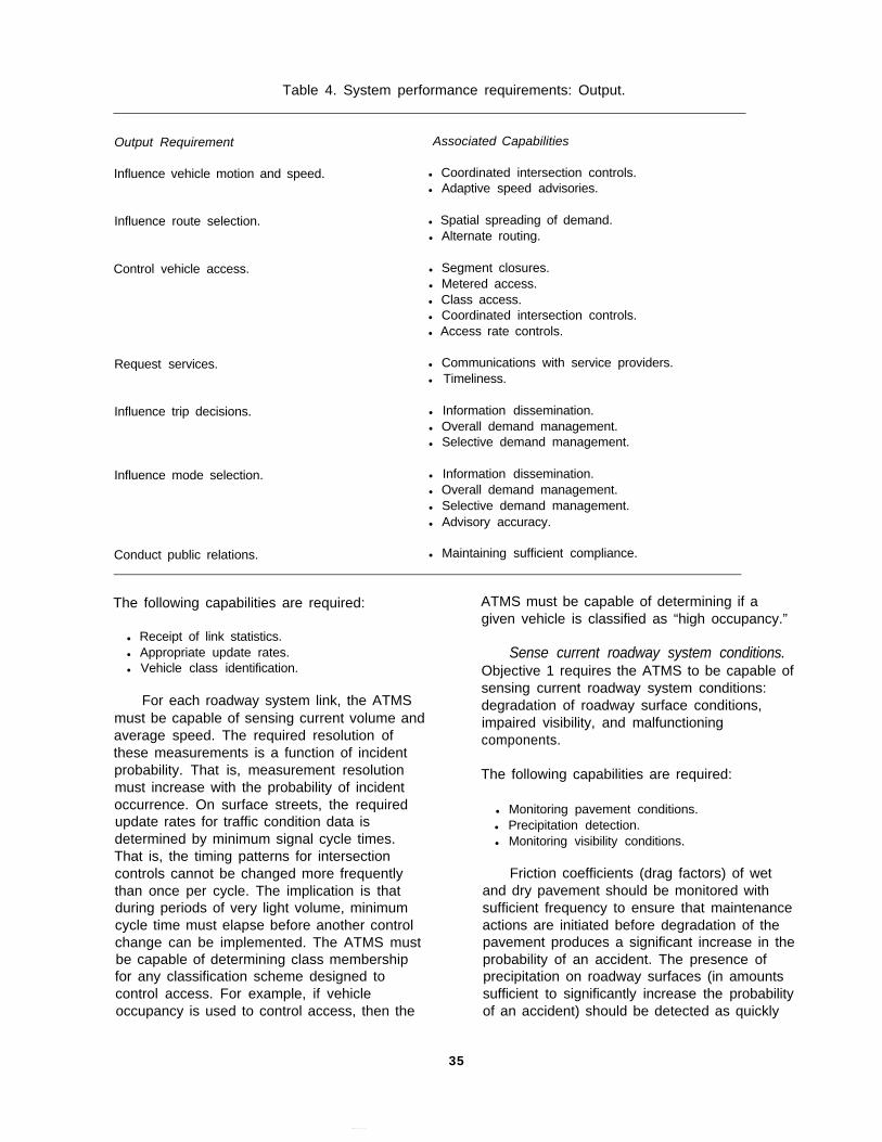
Table 4. System performance requirements: Output.
Output Requirement
Influence vehicle motion and speed.
Associated Capabilities
l Coordinated intersection controls.l Adaptive speed advisories.
Influence route selection. l Spatial spreading of demand.l Alternate routing.
Control vehicle access. l Segment closures.l Metered access.l Class access.l Coordinated intersection controls.l Access rate controls.
Request services. l Communications with service providers.l Timeliness.
Influence trip decisions. l Information dissemination.l Overall demand management.l Selective demand management.
Influence mode selection. l Information dissemination.l Overall demand management.l Selective demand management.l Advisory accuracy.
Conduct public relations. l Maintaining sufficient compliance.
The following capabilities are required:
l Receipt of link statistics.l Appropriate update rates.l Vehicle class identification.
For each roadway system link, the ATMSmust be capable of sensing current volume andaverage speed. The required resolution ofthese measurements is a function of incidentprobability. That is, measurement resolutionmust increase with the probability of incidentoccurrence. On surface streets, the requiredupdate rates for traffic condition data isdetermined by minimum signal cycle times.That is, the timing patterns for intersectioncontrols cannot be changed more frequentlythan once per cycle. The implication is thatduring periods of very light volume, minimumcycle time must elapse before another controlchange can be implemented. The ATMS mustbe capable of determining class membershipfor any classification scheme designed tocontrol access. For example, if vehicleoccupancy is used to control access, then the
ATMS must be capable of determining if agiven vehicle is classified as “high occupancy.”
Sense current roadway system conditions.Objective 1 requires the ATMS to be capable ofsensing current roadway system conditions:degradation of roadway surface conditions,impaired visibility, and malfunctioningcomponents.
The following capabilities are required:
l Monitoring pavement conditions.l Precipitation detection.l Monitoring visibility conditions.
Friction coefficients (drag factors) of wetand dry pavement should be monitored withsufficient frequency to ensure that maintenanceactions are initiated before degradation of thepavement produces a significant increase in theprobability of an accident. The presence ofprecipitation on roadway surfaces (in amountssufficient to significantly increase the probabilityof an accident) should be detected as quickly
35

as possible. The ATMS must be capable ofdetecting degraded visibility conditions andinterpreting degrees of degradation. Thedegree to which visibility is degraded (on agiven roadway segment) should be representedas a percentage (P) of that segment’s desiredoperating speed under benign conditions. Pshould be specified in accordance with driverreaction times predicted for the degradedconditions. That is, lower P values would beassociated with longer reaction times (andhigher degrees of degradation). Degradedvisibility could arise from meteorologicalconditions such as fog, low ambient lightinglevels (e.g., as exists in tunnels), and glarecreated by direct sunlight shortly after sunriseand shortly before sunset.
Sense incident location and severity.Objective 2 requires the ATMS to be capable ofsensing the presence of incidents.
The following capabilities are required:
l Timely detection.l Detection of incident type and severity.l Determination of incident location.l Estimation of expected duration.l Sufficient update rates.
The ATMS should detect incidents asquickly as possible under all traffic conditions.During peak demand times, the (potential)negative impact on traffic conditions warrantsrapid detection. Information regarding thenature and severity of the incident must bereceived with sufficient accuracy to permitproper response selection. Incident locationmust be determined with sufficient accuracy topermit the routing of incident responders via themost direct route. For incidents located at asurface street intersection, the respectiveintersection can be specified. For incidentslocated between intersections, the street andblock can be specified. On limited accessroadways, incident location should be specifiedwith sufficient accuracy to permit identificationof the nearest access ramp [or the nearest milemarker if the adjacent ramps are separated bymore than 1.61 km (1 mi)]. The duration of theincident’s impact on effective capacity must beestimated with sufficient accuracy andtimeliness to allow remedial measures to beselected and implemented. These inputs mustbe updated given any change in incident
conditions that will change traffic managementtactics.
Track location and destination ofemergency service vehicles. Objective 3requires the ATMS to track emergency vehiclelocations and to be aware of their destinationswith sufficient accuracy to implement prioritycontrol when appropriate.
The following capabilities are required:
l Knowledge of vehicle route.l Knowledge of vehicle position.l Sufficient update rates.
The destination of emergency vehiclesmust be known in sufficient detail such that allsegments of planned routes may beanticipated/designated at the time of dispatch(or as soon thereafter as such information canbe determined and relayed by the dispatcher).On surface streets, position accuracy of lessthan one block is required in order for prioritycontrol of traffic signals to be implemented andcoordinated. Assuming a nominal block lengthof 200 m (one eighth of a mile), the resolutionof vehicle position data should be less than 200m. These requirements may be somewhatrelaxed on freeways. Vehicle route data shouldbe updated as soon as possible whenever achange in intended route is made. Vehicleposition data must be updated with sufficientfrequency to support priority control of trafficsignals. Assuming a city block of 200 m and avehicle moving at a top speed of 1.6 km perminute (c. 60 mi/h), updates on vehicle positionshould be received at least every one-eighth ofa minute (7.5 s).
Track location and movement ofcommercial rail traffic. Objective 1 requires theATMS to track the progression of commercialrail traffic through various intersections of therail and roadway systems. Blockage of theseintersections can be a significant source ofdelay for roadway traffic.
The following capabilities are required:
l Sufficient lead time.l Knowledge of expected duration of
intersection blockage.
36
A train’s blockage of a crossing should beanticipated by the ATMS with sufficient leadtime to adjust traffic signal patterns in thevicinity and to post appropriate advisorymessages. The exact lead time will varyaccording to street layout in the vicinity of eachcrossing. Expected blockage duration shouldbe known with sufficient accuracy to permit theposting of valid advisories where applicable. Ata minimum, advisories should indicateapproximate remaining delay time. Whenappropriate, advisories should indicate analternate route.
Receive current and forecasted weatherconditions. Weather conditions, particularlyprecipitation, can have a major impact on trafficconditions. The ATMS is required byObjectives 1 and 2 to receive input on anycurrent and predicted weather conditions thatmay affect (1) roadway availability and (2)incident probability. The accuracy of this inputmust be sufficient to allow the ATMS todetermine appropriate responses.
The following capabilities are required:
l Knowledge of area-wide conditions.l Knowledge of localized conditions.l Tracking of current conditions.
Forecasts of weather conditions that willnegatively affect travel conditions throughout allor a significant part of the ATMS service area(e.g., a winter storm) should be known inadvance such that appropriate advisories maybe posted. For severe conditions (thosewarranting attempts to significantly reducedemand), a minimum of 24 h advance notice isrequired. This lead time will allow informationto be disseminated and contingency plans to beestablished. Forecasts of those weatherconditions that will have a localized impact ontravel (e.g., a severe thunderstorm cell) shouldbe known when the forecasts can identify theprobable affected area. When inclementweather conditions exist in any part of theATMS service area, progression of thoseconditions through the service area should betracked as closely as possible such thatcontrols and advisories can be appropriatelyadjusted.
Obtain demand for transportation facilities.Objective 4 requires the ATMS to obtain inputsregarding the demand for metropolitan-areatransportation facilities.
The following capabilities are required:
l Receipt of strategic planning inputs.l Receipt of special event information.l Input resolution.l Sufficient lead time.
Plans for any new housing, industrial, andcommercial developments that will affect overalldemand levels and patterns should be receivedby the ATMS. Information related to specialevents (time, location, and expectedattendance) should be received by the ATMSfor any event expected to generate abnormaldemand levels or patterns. Transportationdemand inputs must be of sufficient accuracy toallow identification of probable overload, whereoverload is caused by excessive roadwaysystem demand (chronic or acute). Demandinputs should be received with sufficient leadtime to permit problem identification andimplementation of demand regulationmeasures.
Receive indicators of public confidence inATMS. Objective 5 requires the ATMS toreceive inputs indicating the level of publicconfidence in the ATMS.
The following capabilities are required:
l Receipt of current indicators.l Receipt of trend indicators.
The ATMS must receive inputs that indicatecurrent levels of public confidence. Theseindicators identify any lapses in publicconfidence that negatively affect the ATMS'sability to fulfill its other objectives. The ATMSmust receive inputs that indicate trends ofincreasing/decreasing public confidence. Theaccuracy and timeliness of this input must besufficient to permit implementation of preventivemeasures.
37
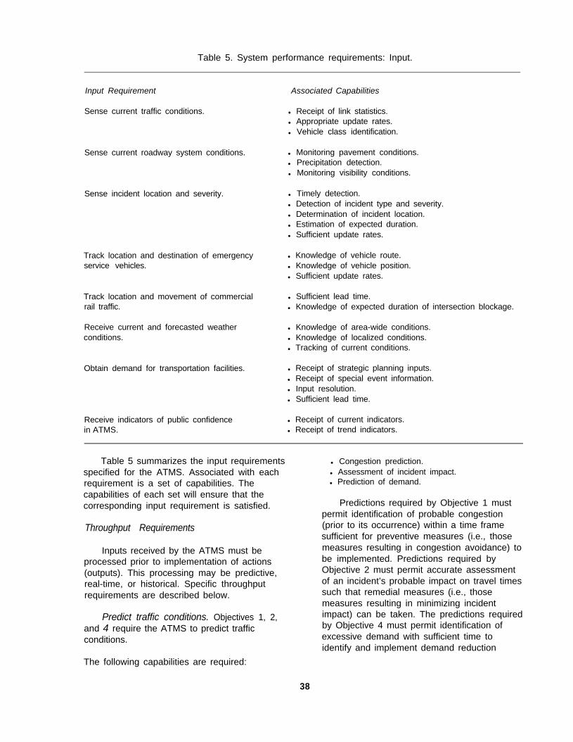
Table 5. System performance requirements: Input.
Input Requirement Associated Capabilities
Sense current traffic conditions. l Receipt of link statistics.l Appropriate update rates.l Vehicle class identification.
Sense current roadway system conditions.
Sense incident location and severity.
l Monitoring pavement conditions.l Precipitation detection.l Monitoring visibility conditions.
l Timely detection.l Detection of incident type and severity.l Determination of incident location.l Estimation of expected duration.l Sufficient update rates.
Track location and destination of emergencyservice vehicles.
l Knowledge of vehicle route.l Knowledge of vehicle position.l Sufficient update rates.
Track location and movement of commercialrail traffic.
l Sufficient lead time.l Knowledge of expected duration of intersection blockage.
Receive current and forecasted weatherconditions.
l Knowledge of area-wide conditions.l Knowledge of localized conditions.l Tracking of current conditions.
Obtain demand for transportation facilities. l Receipt of strategic planning inputs.l Receipt of special event information.l Input resolution.l Sufficient lead time.
Receive indicators of public confidencein ATMS.
l Receipt of current indicators.l Receipt of trend indicators.
Table 5 summarizes the input requirementsspecified for the ATMS. Associated with eachrequirement is a set of capabilities. Thecapabilities of each set will ensure that thecorresponding input requirement is satisfied.
Throughput Requirements
Inputs received by the ATMS must beprocessed prior to implementation of actions(outputs). This processing may be predictive,real-time, or historical. Specific throughputrequirements are described below.
Predict traffic conditions. Objectives 1, 2,and 4 require the ATMS to predict trafficconditions.
l Congestion prediction.l Assessment of incident impact.l Prediction of demand.
Predictions required by Objective 1 mustpermit identification of probable congestion(prior to its occurrence) within a time framesufficient for preventive measures (i.e., thosemeasures resulting in congestion avoidance) tobe implemented. Predictions required byObjective 2 must permit accurate assessmentof an incident’s probable impact on travel timessuch that remedial measures (i.e., thosemeasures resulting in minimizing incidentimpact) can be taken. The predictions requiredby Objective 4 must permit identification ofexcessive demand with sufficient time toidentify and implement demand reduction
The following capabilities are required:
38

strategies (i.e., those that reduce demand toacceptable levels).
Identify maintenance and upgrade needs.Objectives 1, 2, and 5 require the ATMS toidentify maintenance and upgraderequirements.
The following capabilities are required:
l Identification of roadway surfacemaintenance needs.
l Identification of electronic componentneeds.
l Identification of training needs.l Timely identification of needs.
The ATMS must identify preventive andremedial maintenance needs for roadwaysurfaces and for the roadway system’selectronic components (e.g., sensors,processors, effectors). The ATMS must also becapable of identifying hardware and softwareupgrade needs. The ATMS must identifytraining needs (in order to maintain andupgrade the skills of its personnel). All needsmust be identified when the deterioration of anypart of the roadway system will negativelyimpact the ATMS’s ability to satisfy itsobjectives.
Select responses. All five objectivesrequire some form of response selection.Response selection involves identification ofresponse options, assessment of those optionsin terms of feasibility and predicted result, andselection of one or more of those options forimplementation.
The following capabilities are required:
l Selection of traffic management tactics.l Selection of incident management
approach.l Provision of emergency service support.l Demand regulation.l Maintenance of public confidence.
Objective 1 requires the selection of thosetraffic management tactics that will avoid
congestion. If congestion cannot be avoided,tactics to dissipate it in a timely manner arerequired. Implicit requirements are aknowledge of traffic management principles andan ability to estimate the impact of trafficmanagement tactics on current trafficconditions. Objective 2 requires the selectionof those incident management tactics that willminimize an incident’s impact on travel timessuch that safety is not compromised. Implicitrequirements are a knowledge of incidentmanagement principles, an ability to predict anincident’s impact on traffic conditions over time,and an ability to match available responseresources to the requirements of a specificincident. Objective 3 requires selection oftraffic management and incident managementtactics necessary to facilitate the provision ofemergency services. For example, the ATMSmust identify situations in which the provision ofpriority control of traffic signals is appropriate.Implicit requirements are a knowledge of thetypes of available emergency services and theirrespective capabilities. Objective 4 requiresselection of those demand regulation strategies(for overall demand reduction) and demandregulation tactics (for special events) that willreduce the demand to acceptable levels.Implicit requirements are a knowledge of thecapabilities and limitations of alternatetransportation modes and an ability to estimatethe impact of demand regulation strategies andtactics on roadway system demand. Objective5 requires the selection of those strategies thatwill maintain and improve public confidence inthe ATMS. Implicit requirements are aknowledge of public relations principles and anability to estimate the impact of any ATMSaction (tactical or strategic) on publicconfidence.
Table 6 summarizes the throughputrequirements specified for the ATMS. Eachrequirement is assigned a set of capabilities,where the capabilities of this set facilitatesatisfactory throughput performance.
Support Requirements
In addition to the primary functionalperformance requirements imposed by system
39

Table 6. System performance requirements: Throughput.
Throughput Requirement
Predict traffic conditions.
Associated Capabilities
l Congestion prediction.l Assessment of incident impact.l Prediction of demand.
Identify maintenance and upgrade needs. l Identifying roadway surface maintenance needs.l Identifying electronic component needs.l Identifying training needs.l Timely identification of needs.
Select responses. l Selection of traffic management tactics.l Selection of incident management approach.l Provision of emergency service support.l Demand regulation.l Maintaining public confidence.
objectives, a number of ancillary (support)requirements are necessary. Suchrequirements support the overall mission of theATMS and are discussed below.
Collect and store traffic data. Thisrequirement is associated with forecasting andstrategic planning. Traffic data supportplanning for those roadway systemimprovements and major special events(parades, football bowl games, etc.) that disruptnormal traffic flows.
Collect and store incident data. Throughthis requirement, lessons learned and incidentmanagement strategies are documented.
Collect data for electronic toll and tax.Included are data on individual vehicles subjectto toll or tax, as well as aggregate data thatprovide a basis for congestion pricing.
Conduct operator training. Operatortraining is accomplished through the simulationcapability of the ATMS. Training coursesinclude units on major hazardous incidentmanagement and emergency weatherconditions, as well as normal operations.
Conduct transportation planning. Planningactivities include strategic, special event, andcontingency planning. These activities mayinclude interaction with other agencies (e.g.,
police) or other transportation modalities (e.g.,rail transit).
Perform administrative support.Administrative support is required in suchmatters as fiscal planning and budget tracking,maintenance of personnel records, andreceiving and implementing policy directivesfrom appropriate agencies.
Table 7 summarizes the supportrequirements specified for the ATMS. For eachrequirement, a set of capabilities is identified.These capabilities will ensure that thecorresponding support requirement is satisfied.
RESULTS: FUNCTIONAL DEFINITION
ATMS functionality is a product of ATMSobjectives, and, in turn, system performancerequirements. That is, ATMS functionalityrepresents the means by which ATMSobjectives and system performancerequirements are satisfied. In what follows, thefunctions required by each objective arediscussed. In these discussions, names of thetop-level functions are printed in boldface typewhen introduced, and subfunctions associatedwith each top-level function are described.Fulfillment of an objective requires thosefunctions specified for previous objectives, inaddition to any new functions specific to theobjective under consideration. For example,the functions required by Objective 3 (assist in
40
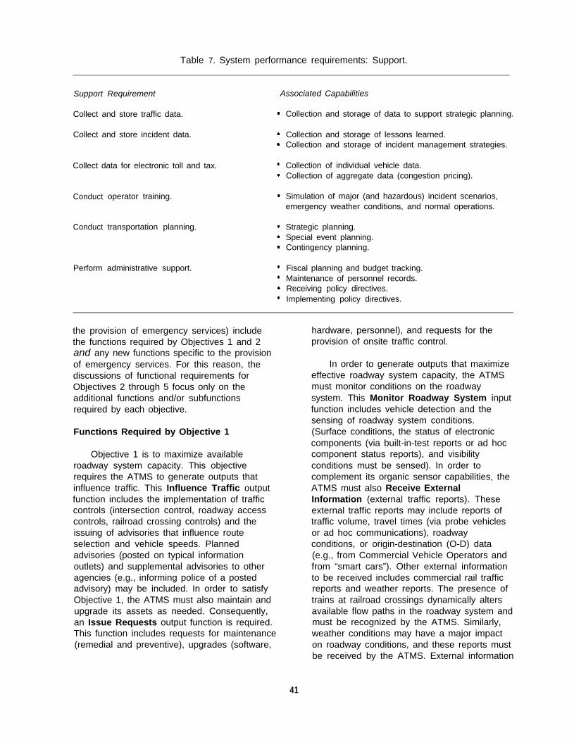
Table 7. System performance requirements: Support.
Support Requirement Associated Capabilities
Collect and store traffic data.
Collect and store incident data.
Collect data for electronic toll and tax. l
Conduct
Conduct
operator training.
transportation planning.
Perform administrative support. l
l
l
Collection and storage of data to support strategic planning.
Collection and storage of lessons learned.Collection and storage of incident management strategies.
Collection of individual vehicle data.Collection of aggregate data (congestion pricing).
Simulation of major (and hazardous) incident scenarios,emergency weather conditions, and normal operations.
Strategic planning.Special event planning.Contingency planning.
Fiscal planning and budget tracking.Maintenance of personnel records.Receiving policy directives.Implementing policy directives.
the provision of emergency services) includethe functions required by Objectives 1 and 2and any new functions specific to the provisionof emergency services. For this reason, thediscussions of functional requirements forObjectives 2 through 5 focus only on theadditional functions and/or subfunctionsrequired by each objective.
Functions Required by Objective 1
Objective 1 is to maximize availableroadway system capacity. This objectiverequires the ATMS to generate outputs thatinfluence traffic. This Influence Traffic outputfunction includes the implementation of trafficcontrols (intersection control, roadway accesscontrols, railroad crossing controls) and theissuing of advisories that influence routeselection and vehicle speeds. Plannedadvisories (posted on typical informationoutlets) and supplemental advisories to otheragencies (e.g., informing police of a postedadvisory) may be included. In order to satisfyObjective 1, the ATMS must also maintain andupgrade its assets as needed. Consequently,an Issue Requests output function is required.This function includes requests for maintenance(remedial and preventive), upgrades (software,
hardware, personnel), and requests for theprovision of onsite traffic control.
In order to generate outputs that maximizeeffective roadway system capacity, the ATMSmust monitor conditions on the roadwaysystem. This Monitor Roadway System inputfunction includes vehicle detection and thesensing of roadway system conditions.(Surface conditions, the status of electroniccomponents (via built-in-test reports or ad hoccomponent status reports), and visibilityconditions must be sensed). In order tocomplement its organic sensor capabilities, theATMS must also Receive ExternalInformation (external traffic reports). Theseexternal traffic reports may include reports oftraffic volume, travel times (via probe vehiclesor ad hoc communications), roadwayconditions, or origin-destination (O-D) data(e.g., from Commercial Vehicle Operators andfrom “smart cars”). Other external informationto be received includes commercial rail trafficreports and weather reports. The presence oftrains at railroad crossings dynamically altersavailable flow paths in the roadway system andmust be recognized by the ATMS. Similarly,weather conditions may have a major impacton roadway conditions, and these reports mustbe received by the ATMS. External information
41

may be received either electronically or throughverbal communication with outside agencies orthe public.
Exercising its throughput functionality, theATMS assesses available data in order todetermine output requirements. The functionSelect Traffic Management Tactics includesassessing network conditions and (given thoseconditions) determining optimal controlschemes. Assessing network conditionsincludes calculating current system load and(based on current load) anticipating thevery-near-term load. Determining an optimalcontrol scheme involves identifying trafficcontrol options (where one option alwaysavailable is to continue the current controlscheme), predicting traffic conditions in thenear term given those options, assessing thepredictions, and selecting the best option.Predictions can be based on expected changesin conditions (e.g., as a function of changingweather conditions), as well as current data.
Maximizing effective capacity also requiresthe maintenance and upgrading of roadwaysystem components. Thus, a secondthroughput function required by this objective isto Determine System Welfare Needs. Thisfunction involves a self-assessment of systemeffectiveness and the determination ofmaintenance and upgrade requirements.Remedial and preventive maintenancerequirements are determined. Upgraderequirements might include upgrades tohardware, software, or personnel. Personnelupgrades might involve new hires or additionaltraining for existing personnel.
Satisfying Objective 1 also requires thespecification of support functions. The ATMSmust Maintain Records: store and retrievenetwork data to be used in (1) predicting trafficconditions (e.g., as a function of time-of-day orday-of-week) and (2) self-assessment of systemeffectiveness The ATMS must also ProvideTraining for operators and maintainers andDevelop Traffic Management Plans (strategic,special event, and contingency plans).Contingency plans include those to beimplemented during extreme weatherconditions, disasters, or other potential majorproblems. Finally, the ATMS must PerformAdministrative Duties in areas such as
financial management, policy development,personnel administration, and data basemanagement.
Functions Required by Objective 2
The second objective is to minimize theimpact of incidents. Much of the requiredfunctionality is obtained from the functionsderived in response to Objective 1. (A majorcomponent of minimizing incident impact isoptimal management of traffic around thoseincidents.) In order to minimize incident impact,the ATMS must facilitate incident clearance.Thus, the output function Issue Requests isexpanded to include subfunctions that issuerequests for (1) incident services (e.g., towing,medical, police, fire) and (2) additionalinformation from external agencies. For someincidents the ATMS may Provide Informationto other agencies (or the public): incidentreports and incident management reports.Issuing requests and providing information tothe most frequently involved agencies/outletsare typically performed through direct electroniclinks. For atypical situations, special reportsmay be provided through personalcommunication.
Minimizing the impact of incidents requiresthe TMS to detect the presence of incidents asrapidly as possible. Detection is accomplishedin two ways. First, as input, the ReceiveExternal Information function is expanded toinclude subfunctions that receive incidentreports from the general public and from publicauthorities such as the police. A newsubfunction that focuses on the receipt ofincident response reports is added. Second,the ATMS must review traffic data foranomalies in flow patterns, where suchanomalies may indicate the presence of anincident. (Note that anomalies could arise inthe absence of an incident.) An AssessAnomalies throughput function enables theATMS to identify anomalies and determineanomaly sources. Determining the need forservices (and in some cases identifying thesource of an anomaly) requires the ATMS toobtain more information than is typicallyassociated with traffic conditions existing in thevicinity of an incident. If the Monitor RoadwaySystem input function is expanded to include asubfunction that enables the ATMS to observe
42
incident sites, service requirements can beassessed directly. This new subfunction alsoprovides another means for the ATMS to verifyincident data and monitor incident clearanceprocedures.
Facilitating the clearance of an incidentrequires incident management. Some incidentsfall solely within the province of the ATMS;other incidents (e.g., those involving threats tohuman life or public safety) may requireinvolvement of other agencies. Thus, asthroughput the ATMS must Select ATMSResponses to Incidents: determine theATMS’s responsibilities relative to otheragencies, determine the specific incidentservice requirements, and determineappropriate ATMS responses.
Support functionality implied by Objective 2includes an expansion of the Maintain Recordsfunction to include the maintenance of incidentdata records (storing and retrieving dataelectronically or through hardcopies). Anexpansion of the Provide Training function toinclude providing incident management trainingis required. For incidents involving additionalagencies, the appropriate role for the ATMSmay require it to Provide InteragencyCoordination: maintaining interagencycommunications and coordinating multi-agencyincident responses.
Functions Required by Objective 3
Objective 3 requires the ATMS to supportthe provision of emergency services. In manycases emergency services are provided inresponse to roadway incidents; therefore,because of Objective 2, most of thefunctionality required by Objective 3 is alreadydefined. The output functions required tosupport incident management are sufficient tosupport provision of emergency servicevehicles. Consequently, no additional outputfunctions are added by this objective.
Objective 3 does impose requirements foradditional input, throughput, and supportfunctions. As input, the Receive ExternalInformation function must be expanded toinclude subfunctions that receive other types ofemergency response reports (i.e., emergencyresponses unrelated to roadway incidents):
interagency response data and supplementalemergency response reports. For example, amajor fire in the metropolitan area, while not aroadway incident, may require the ATMS toassist in managing traffic near the site and thusfacilitate a speedy response by fire, police, andmedical services. A second example is ahazardous materials release that necessitatesevacuation of the affected (surrounding) area.The evacuation may create traffic conditionsrequiring the implementation of special trafficmanagement strategies and the closing ofroadway segments as a means of enforcing theevacuation. The throughput function SelectTraffic Management Tactics must be expandedto include a subfunction that determines specialvehicle support measures. This subfunctionincludes determining the requirements forATMS services and tracking special vehicles onthe roadway system.
The support function Provide InteragencyCoordination must also be expanded to includethe coordination of multi-agency responses toother emergencies (i.e., emergencies that areunrelated to roadway incidents).
Functions Required by Objective 4
Objective 4 focuses on the regulation ofroadway system demand. Most of thefunctionality required by Objectives 1 through 3has considered tactical operations, with somestrategic planning as a support function.Accomplishing Objective 4 imposesrequirements for more extensive functionality atthe strategic level and for some expansion offunctionality at the tactical level.
At the tactical level, Objective 4 requiresthe ATMS to provide outputs that assist indemand regulation. The output function IssueAdvisories must be expanded to includesubfunctions that issue travel advisories (e.g.,advisories intended to influence travelers’trip-making decisions) and mode selectionadvisories (e.g., advisories enabling travelers toweigh the advantages/disadvantages of travelvia public transportation versus carpool versusSOV). Advisories are either planned (postedon typical information outlets) or supplemental(provided to other agencies as needed). At thestrategic level, the ATMS must provideinformation in support of demand regulationefforts. The Provide Information function must
43

be expanded to include subfunctions thatprovide traffic data (historical or real-time), aswell as reports and recommendations, insupport of demand regulation efforts.
As input, the ATMS must ReceiveRequests for Information: requests forhistorical data and simulation studies that willproduce reports and recommendations relatedto demand regulation. The Receive ExternalInformation function must be expanded toinclude a subfunction that receives data fromother transportation systems. These systemsmay be other traffic management centers(TMC’s) or alternate transportation modes (e.g.,public transportation).
Special events (e.g., major sporting events,conventions, concerts) often generate a highdemand for transportation services, and theymay create unusual traffic flow patterns. Trafficmanagement planning for special events wasincluded in Objective 1. Objective 4 alsorequires the ATMS to be involved in multimodaldemand regulation efforts for special events.Thus, the Receive External Information functionmust be expanded to include a subfunction thatreceives special event reports electronically orthrough verbal communication. Reportsdescribing the event, reports from other cities inwhich similar events have been held, andreports from other agencies that documentspecial event management strategies (e.g.,provisions for extra police patrols) could beincluded.
As a throughput requirement, the ATMSmust Conduct Simulations to SupportTransportation Planning. These simulationstudies assess multimodal demand andcapacity and subsequently determine anoptimal demand regulation scheme. Theyproduce reports and recommendations that aretransmitted to a requester. Simulation studiesmay generate predictions that are quitedifferent from those provided by the functionSelect Traffic Management Tactics. The latterpredictions are concerned solely with roadwaysystem traffic and do not consider othertransportation modes. Predictions associatedwith the function Select Traffic ManagementTactics are based on current traffic conditionsand existing configurations of the roadwaysystem. In contrast, the predictions generated
from simulation studies may well involve othertransportation modes, and they could alsoinvolve different demand pattern assumptionsor different roadway system configurations.Such simulation studies, for example, couldsupport planning for the implementation ofinnovative IVHS technologies (e.g.,technologies incorporatingspecially-instrumented, restricted access laneson certain roadways.)
Two support functions must be expandedto accommodate the requirements of Objective4. The Provide Training function must beexpanded to include a subfunction that providesspecial event training. (Routine trafficmanagement training could include lessons thatfocus on traffic management for special events.However, expanded functionality is required forsituations in which specialized training forspecific events is of interest; in particular, thoseinstances in which individuals from otheragencies participate in training.) The ProvideInteragency Coordination function must beexpanded to include a subfunction thatcoordinates multi-agency transportationplanning.
Functions Required by Objective 5
Objective 5 is to create and maintain publicconfidence in the ATMS. The ATMS satisfiesObjective 5, to a great extent, through itssuccessful attainment of Objectives 1 through4; however, Objective 5 does require the ATMSto actively influence public confidence. Asoutput, the Provide Information function mustbe expanded to include a subfunction thatprovides public relations information. As input,the function Receive Requests for Informationmust be expanded to include a subfunction thatreceives requests for public relationsinformation. Also as input, the ReceiveExternal Information function must be expandedto include a subfunction that receives publiccomments. These comments could arrive fromother agencies, businesses, or private citizens.
As a throughput function, the ATMS mustAssess Public Confidence. Such assessmentincludes monitoring travelers’ compliance withboth general and current ATMS advisories,assessing public comments received eitherdirectly (written or verbal comments) or via
44
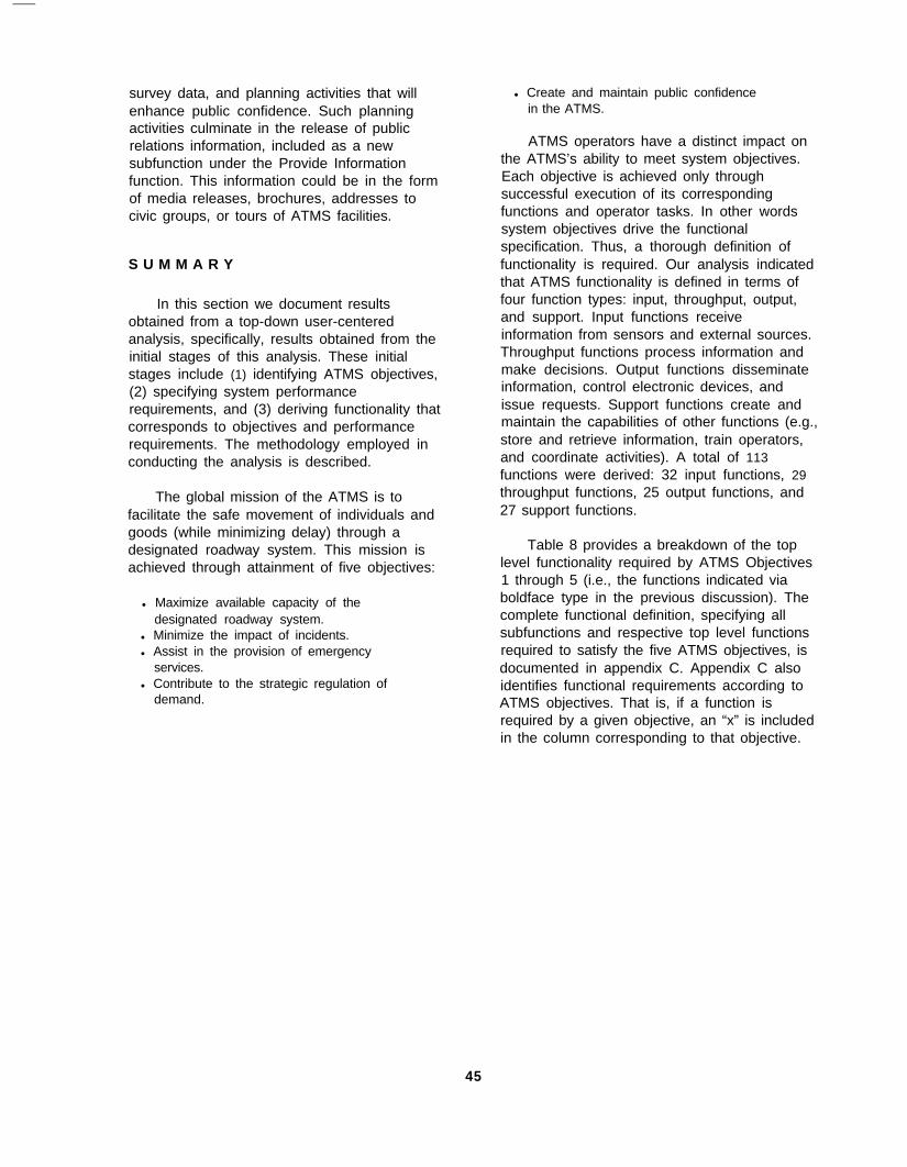
survey data, and planning activities that willenhance public confidence. Such planningactivities culminate in the release of publicrelations information, included as a newsubfunction under the Provide Informationfunction. This information could be in the formof media releases, brochures, addresses tocivic groups, or tours of ATMS facilities.
S U M M A R Y
In this section we document resultsobtained from a top-down user-centeredanalysis, specifically, results obtained from theinitial stages of this analysis. These initialstages include (1) identifying ATMS objectives,(2) specifying system performancerequirements, and (3) deriving functionality thatcorresponds to objectives and performancerequirements. The methodology employed inconducting the analysis is described.
The global mission of the ATMS is tofacilitate the safe movement of individuals andgoods (while minimizing delay) through adesignated roadway system. This mission isachieved through attainment of five objectives:
l Maximize available capacity of thedesignated roadway system.
l Minimize the impact of incidents.l Assist in the provision of emergency
services.l Contribute to the strategic regulation of
demand.
l Create and maintain public confidencein the ATMS.
ATMS operators have a distinct impact onthe ATMS’s ability to meet system objectives.Each objective is achieved only throughsuccessful execution of its correspondingfunctions and operator tasks. In other wordssystem objectives drive the functionalspecification. Thus, a thorough definition offunctionality is required. Our analysis indicatedthat ATMS functionality is defined in terms offour function types: input, throughput, output,and support. Input functions receiveinformation from sensors and external sources.Throughput functions process information andmake decisions. Output functions disseminateinformation, control electronic devices, andissue requests. Support functions create andmaintain the capabilities of other functions (e.g.,store and retrieve information, train operators,and coordinate activities). A total of 113functions were derived: 32 input functions, 29throughput functions, 25 output functions, and27 support functions.
Table 8 provides a breakdown of the toplevel functionality required by ATMS Objectives1 through 5 (i.e., the functions indicated viaboldface type in the previous discussion). Thecomplete functional definition, specifying allsubfunctions and respective top level functionsrequired to satisfy the five ATMS objectives, isdocumented in appendix C. Appendix C alsoidentifies functional requirements according toATMS objectives. That is, if a function isrequired by a given objective, an “x” is includedin the column corresponding to that objective.
45
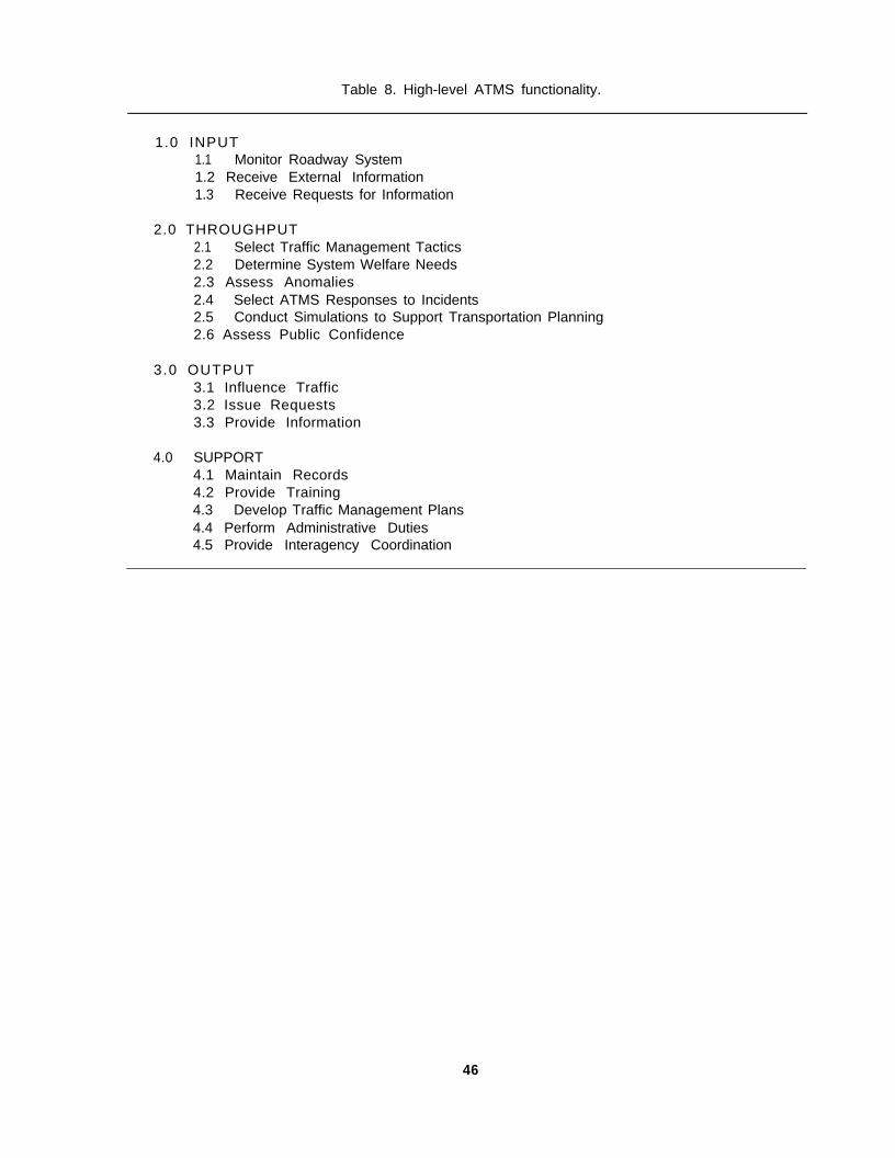
Table 8. High-level ATMS functionality.
1.0 INPUT1.1 Monitor Roadway System1.2 Receive External Information1.3 Receive Requests for Information
2.0 THROUGHPUT2.1 Select Traffic Management Tactics2.2 Determine System Welfare Needs2.3 Assess Anomalies2.4 Select ATMS Responses to Incidents2.5 Conduct Simulations to Support Transportation Planning2.6 Assess Public Confidence
3.0 OUTPUT3.1 Influence Traffic3.2 Issue Requests3.3 Provide Information
4.0 SUPPORT4.1 Maintain Records4.2 Provide Training4.3 Develop Traffic Management Plans4.4 Perform Administrative Duties4.5 Provide Interagency Coordination
46

SECTION 3.FUNCTIONAL LOCATION
INTRODUCTION
The functions required to satisfy ATMSobjectives have been defined in terms of fourfunction types: input, throughput, output, andsupport. (6,13) Ultimately, a total of 113 functionswere specified. (6,13) Of this total, 32 inputfunctions and 29 throughput functions werespecified; 25 functions were designated asoutput functions, and 27 functions weredesignated as support functions.
In what follows, the theoretical frameworkguiding ATMS function allocation, referred to asoperator role theory, is introduced. Functionallocation is the process through which humanfactors analysts specify how system functionswill be executed (i.e., through a humanoperator, through a machine, or through thejoint effort of a human operator and amachine). The fundamentals of operator roletheory and the manner in which it is applied toATMS functions are described. A discussion ofresults, including an example of the functionallocation methodology, follows. Finally, a briefsummary statement and implications derivedfrom results of the function allocation processare presented.
OPERATOR ROLES AND FUNCTIONALLOCATION: THEORETICAL FRAMEWORK
Operator role theory provides a frameworkfor guiding ATMS function allocation. Withinthis framework, a continuum of operator roles isdefined such that at one end of the continuum,a function is allocated solely to a humanoperator, and at the opposite end, a function isallocated solely to a machine. Between theextremes, function performance is shared byhuman operator and machine components.Note that a role refers to the collection of tasksor activities an individual performs within agiven context, rather than a just specific task.An operator can have one role in a givenfunction and another role in a second function.Within each role the operator may have severaltasks.
Operator role theory was originallydeveloped to describe human activities requiredfor the operation of air defense systems. (14)
Subsequently, operator role theory has beengeneralized to apply to all types ofhuman-machine systems. It can be applied asa prescriptive (as well as descriptive) tool.
In considering ATMS design from a humanfactors perspective, one of our primaryobjectives has been to designate theappropriate human operator role for eachfunction. As a consequence of such roledesignation, the level of automation associatedwith each function can be established. Thissection presents the results of our applicationof operator role theory to ATMS functionality.Here, operator role theory supports the functionallocation process, enabling analysts to specifythe agent of function execution (i.e., humanoperator, machine, operator-machinecombination) for each ATMS function.
OPERATOR ROLE THEORY
Design of the ATMS from a human factorsperspective requires more than an assessmentof individual display and control componentsand their arrangement in a set of workstations.While workstation design is critical, humanfactors inputs to the design process must affecthigh-level design philosophy. Specifically, therationale underlying the allocation of functionsamong human operators and machines mustbe driven by human factors considerations. Inthis manner, system and operator performanceis optimized.
Operator role theory was applied in theallocation of ATMS functions. According to thistheoretical framework, a continuum of operatorroles is defined such that at one extreme of thecontinuum a function is allocated solely to ahuman operator and at the opposite extreme afunction is allocated solely to a machine. Thecontinuum is divided into four regions, whereeach region indicates an operator role (andcorresponding degree of automation). Theseregions are Direct Performer (no automation),Manual Controller (operator performs
4 7
decision-making activities but is assisted bymachine elements that play a role in sensingthe environment, processing input data, orexecuting control actions), SupervisoryController (operator has the ability to override amachine-made decision), and ExecutiveController (operator enables or disables afully-automated function).
Note that three of the four roles are labeledwith the term Controller, indicating that operatoractivities are focused on controlling machinecomponents. The fourth role, labeled with theterm Performer, indicates that directperformance of a function, rather than thecontrol of machine components, is the focus ofoperator activities.
Fundamentals of Operator Role Theory
Operator roles are defined more preciselyby considering the manner in which informationis processed within a function. Each function isdefined in terms of four stages of informationprocessing: input, processing, responseselection, and output. In other words,successful execution of any given function(regardless of function type -- input, throughput,output, support) requires completion of eachstage. At the input stage, information isreceived from an external source by a sensor.At the processing stage, received information ismanipulated by a processor. At the, responseselection stage, a controller decides whatcontrol actions are to be performed. At theoutput stage, an actuator executes controlactions. In order to apply operator role theoryto the function allocation process, the mannerin which humans and machines accomplisheach information processing stage must bespecified.
In both the Direct Performer and ManualController roles, the controller (decision-maker)is human. That is, a human performs responseselection. In the Direct Performer role,however, sensors, processors, and actuatorsare human, while in the Manual Controller role,at least one of these three components is amachine. In both the Supervisory Controllerand Executive Controller roles, responseselection is performed by a machine (i.e., thecontroller is a machine). In the ExecutiveController role, sensors, processors, andactuators are machine components.
Furthermore, except to terminate functionexecution, the human is unable to influencemachine performance. In the SupervisoryController role, however, the human canintervene during the response selection stage(e.g., override a machine-made decision).Additionally, the human may choose to modify.performance of sensors, processors, oractuators.
For a given operator role, human andmachine components associated with the fourinformation processing stages can beconfigured in a number of ways. Thesepossible configurations are provided in table 9.The following notation is used to represent thelevel of operator involvement at eachinformation processing stage.
H: The human is solely responsible forperforming the processing stage.Hm: The human (with machineassistance) performs the processingstage.Mh: The machine (with humanassistance) performs the processingstage.M: The machine is solely responsible forperforming the processing stage.
APPLYING OPERATOR ROLE THEORY TOATMS FUNCTION ALLOCATION
Here, our procedure for allocating ATMSfunctions according to operator role theory isdescribed. Additional details associated withthis procedure are presented in reference 7. Ateam of human factors engineers,psychologists, and software engineers analyzedeach lowest-level function. Appropriateness ofassigning either of the two extreme operatorroles (Direct Performer or Executive Controller)to a function was assessed. One of the tworoles was considered appropriate if (1) itsassignment to the function would satisfy thatfunction’s performance requirements and (2) asignificant increase in capabilities could not beexpected by the assignment of a differentoperator role to the function. If the teamdetermined that a Direct Performer role wouldsatisfy performance requirements and nosignificant gains in performance were expectedby the assignment of some other role, it wasassigned to the function. Similarly, if afunction’s performance requirements could be
48
Table 9. Human and machine configurations for operator roles.
lnformation Processing Stage:
Operator Role INPUT PROCESSING RESPONSE SELECTION OUTPUT
DIRECTPERFORMER
H or Hm H H H
MANUALCONTROLLER
H, Hmor M
H, Hm,or M
H H, Hmor M
SUPERVISORYCONTROLLER
Mh or M Mh or M Mh M or Mh
EXECUTIVE M M M MCONTROLLER
met by an Executive Controller role and nosignificant gains in performance were expectedvia some other role, an Executive Controllerrole was designated for that function.
In considering all remaining functions(those assigned neither Direct Performer norExecutive Controller roles), the analystsassessed the appropriateness of ManualController and Supervisory Controller roles.Again, appropriateness was evaluated in termsof the satisfactory achievement of performancerequirements and the expectation of realizingsignificant performance gains through anotherrole assignment. Once the team reached aconsensus on operator role designations,further details of function allocation werecompleted with the four-stage informationprocessing model. For each function, theanalysts considered possible human/machineconfigurations associated with its respectiveoperator role (table 9) and identified theconfiguration that would best meet performancerequirements.
DISCUSSION OF RESULTS
To each of the 113 ATMS functions, anappropriate operator role was assigned.Additionally, a configuration of human andmachine components was specified for eachfunction’s four information processing stages.The Direct Performer role was assigned to 40of the 113 functions, while the Manual
Controller role was assigned to 28 functions.The Supervisory Controller role was assignedto 16 functions, and the Executive Controllerrole was assigned to 29 functions. In whatfollows the general nature of the functionsassociated with each role are discussed.
Direct Performer Functions
The 40 Direct Performer functions weredistributed (according to function type) asfollows: 15 input functions, 6 throughputfunctions, 7 output functions, and 12 supportfunctions. All of the 15 input functions assigneda Direct Performer role represent personalcommunication activities. These functions allowthe ATMS to receive information, reports,comments, and requests from externalagencies or individuals. Such communicationsare facilitated via face-to-face conversation orstandard communications devices (e.g.,telephone, fax transmission, electronic mail).
Of the six throughput functions assigned aDirect Performer role, three are decision-making functions. For these functions,decisions concerning software, hardware, andpersonnel upgrades are the focus. Theremaining three functions are associated withthe formulation of demand regulationrecommendations, the assessment of publiccomments, and the planning of publicconfidence enhancements.
49

The seven output (Direct Performer)functions represent personal communicationactivities. These functions allow the ATMS todisseminate information and requests viapersonal communication channels.
The 12 support functions assigned a DirectPerformer role include 2 clerical functions(storing and retrieving hardcopies of incidentreports), 6 administrative functions, and 4functions requiring coordination between theATMS and other agencies
Manual Controller Functions
The 28 Manual Controller functions weredistributed (according to function type) asfollows: 2 input functions, 8 throughputfunctions, 7 output functions, and 11 supportfunctions. Both of the input (Manual Controller)functions are associated with the observation ofincident sites (i.e., verification of incident dataand the monitoring of incident clearance).Because human operator control of remotesensors (e.g., surveillance cameras), as well asoperator-observation of incident sites, areessential to successful execution of thesefunctions, they are assigned a ManualController role.
Three of the eight throughput (ManualController) functions are decision-makingfunctions that require ATMS responses toincidents. Two of these eight functionsrepresent the control of transportation planningsimulations. The remaining three functions relyupon operator assessment: determining thesource of anomalies in traffic patterns,monitoring general compliance with ATMSadvisories, and assessing data associated withpublic confidence surveys. In these threefunctions, machine capabilities are critical todata processing; however, decision-making isthe sole responsibility of the operator.
Seven output functions are assigned aManual Controller role. All involve thetransmission of reports or requests of suchvolume that personal communication (i.e., aDirect Performer role) is impractical.Consequently, machine capability assistsoperators in the preparation and distribution ofsuch information.
Eleven support functions are assigned aManual Controller role. Four are trainingfunctions. Training programs may rely (to alarge extent) on machine capability, butdecisions concerning content and procedurewill be the function of human instructors/coursecoordinators. Three of these support functionsfocus on planning activities. Again, whileplanners may rely on computer-basedalgorithms (to support long-term strategicplanning activities or perhaps fiscal planningactivities), decision-making responsibilities areassigned to humans. Three additional supportfunctions represent administrative activities.The remaining function facilitates data basemanagement.
Supervisory Controller Functions
The 16 Supervisory Controller functionswere distributed (according to function type) asfollows: 2 input functions and 14 throughputfunctions. The two input (SupervisoryController) functions are associated with thesensing of roadway network conditions (i.e., thesensing of roadway surface conditions and thesensing of visibility conditions). Thesefunctions are judged inappropriate for anExecutive Controller role for the followingreason. Machine-sensing capabilities alone arenot expected to surpass (or even equal) thecombined capabilities of human operators andmachines. Both functions will rely in part onhuman vision. Relying upon their own visualinspection capabilities and heuristic knowledge,operators serving as supervisory controllers willhave the ability to override sensor reports ofroadway surface conditions or visibilityconditions.
The 14 throughput functions assigned aSupervisory Controller role include a majority ofthe principal traffic management activities:assessing current load, predicting near-termtraffic conditions, assessing traffic controloptions, and selecting the optimal controloption. We envision machine-performance ofreal-time traffic management activities, where(in special situations) the operator assupervisory controller will selectively intervenein order to override machine-made decisions.The sheer number of traffic control decisions tobe made in any reasonably large networkprecludes a requirement for operator approvalof all such decisions. Rather, the operator will
50

intervene when his or her domainknowledge/expertise surpasses that of themachine. Routine maintenance decisions willalso be made under supervisory control. Themachine will make decisions associated withremedial and preventive maintenance needs,where all decisions are subject to operatoroverride.
No output or support functions are assigneda Supervisory Controller role. For each ofthese function types, machine capabilities wereeither sufficiently advanced as to suggest theExecutive Controller role, or were so poor as tosuggest that little would be gained fromincorporating machine-made decisions.
Although only 16 functions are assigned aSupervisory Controller role, many represent thecore capabilities in ATMS traffic management.They are Supervisory Controller functionsrather than Executive Controller because of therequirement to maintain operator-in-the-loopcapabilities.
Executive Controller Functions
The 29 Executive Controller functions weredistributed (according to function type) asfollows: 13 input functions, 1 throughputfunction, 11 output functions, and 4 supportfunctions. The 13 input (Executive Controller)functions are associated with the receipt ofelectronically-formatted data from sensors orother systems. For these functions thetechnology required for function execution (withno operator involvement) either exists currentlyor is expected to exist in the IVHS era.
Only one throughput function is assignedan Executive Controller role. This functionfacilitates the tracking of special vehicles (e.g.,emergency vehicles, probe vehicles). Given arequirement to update vehicle position everyfew seconds, we anticipate no benefit fromproviding a means for operator intervention.
The 11 output functions assigned anExecutive Controller role focus on the electronictransmission of information. In these functionsthe content and intended destination of suchinformation is selected in predecessorfunctions, and consequently, the actual transferof information can be performed underexecutive control.
The four support functions assigned anExecutive Controller role are associated withstorage and retrieval of electronic data.
Function Allocation Example
In the example to follow, the functionallocation methodology, as applied to a giventhroughput function, is documented. Thefunction of interest is Function 2.1.1.2:Anticipate Near-Term Traffic Conditions. Thephrase near-term refers to traffic conditions thatwill occur 1 to 5 min in the future. Function2.1.1.2 ensures that such conditions areanticipated. The methodology requires eachfunction to be assigned one of four operatorroles (Direct Performer, Manual Controller,Supervisory Controller, Executive Controller).In this case a Supervisory Controller role wasconsidered appropriate. The role assessmentconducted for Function 2.1.1.2 follows.
Operator Role Assessment
Assessment of Direct Performer Role: Giventhe need to evaluate and make predictions froma complex set of traffic conditions, this functionrequires machine assistance.
Assessment of Executive Controller Role: Thisfunction cannot be achieved under executivecontrol. Although prediction of near-term trafficconditions can be automated, these predictionshave limited fidelity, and the plausibility of suchpredictions would require operator assessment.The validity of a prediction depends on theconditions considered and on the soundness ofthe analysis that forecasts the evolution ofthose conditions. To expect that a predictivetraffic model would account for all relevantcurrent conditions in all circumstances isunreasonable. A random building fire, forexample, could affect traffic on many nearbyroads, yet many predictive models would fail toallow for such a possibility. Because expectingthat all conditions relevant to traffic predictioncould be enumerated as a basis for automationis unreasonable, the operator must bepermitted to intervene in this function.
Conclusion: Neither the Direct Performer rolenor the Executive Controller role is appropriatefor this function. Assessment with respect toManual Controller and Supervisory Controllerroles must be conducted.
5 1
Assessment of Manual Controller Role: Real-time assessment of a large volume of trafficcondition information is required for theexecution of this task. Consequently, for themajority of traffic situations, automation issuitable for task completion. Requiring amanual “closing of the loop” under allconditions would place an unnecessary burdenon the operator. Therefore, this function isinappropriate for the manual controller role.
Assessment of Supervisory Controller Role:Anticipation of the details of near-term trafficconditions involves the processing of a largevolume of data. Clearly, such processingrequires substantial automation. For thisfunction, relying on the output of a near-termpredictive model is reasonable, but under somecircumstances, an operator might be requiredto override or adjust near-term predictions. Theneed for such adjustments would be indicatedeither when an operator recognizes theoccurrence of conditions not handled by thepredictive model, or when the output of thepredictive model is questionable (or possiblyerroneous). Therefore, this function isappropriate for a Supervisory Controller roledesignation.
Role Designation: The Supervisory Controllerrole is recommended for Function 2.1.1.2.
Subsequently, each function is defined interms of four stages of information processing:input, processing, response selection, output.Finally, the level of operator involvementrequired for each information processing stage(H, Hm, Mh, or M) is assigned.
Configuration of Human and MachineComponents
Function 2.1.1.2: Anticipate Near-Term TrafficConditions
Operator Role: Supervisory Controller
Input: (M) Current load assessments androadway system status, external reports (e.g.,incident, weather, incident response,
emergency response) are provided viasoftware.
Processing: (Mh) Input data are provided to anear-term traffic model. From these data, thefollowing road segment-specific information ispredicted: traffic volume, density, speed.
Response Selection: (Mh) In some instances,the operator may have access to morerelevant/accurate input data or may have betterpredictive capabilities than the software. Underthese circumstances, the operator may chooseto modify input information and overridepredictions (or, at a minimum, identifyinaccurate/imprecise predictions).
Output: (M) Predictions derived by this functionare sent via software to Function 2.1.2(Develop Optimal Control Scheme) andFunction 2.1.2 (Determine Special VehicleSupport Measures).
Note that an operator’s ability to interveneat the response selection stage (in order tomodify input information and thus overridemachine-generated predictions or to identifyinaccurate/imprecise predictions) suggests thisfunction’s appropriateness for a supervisorycontroller role. Input and output stages (i.e.,the receipt of input data and the transmission ofnear-term predictions) are automated, wherethe level of operator involvement associatedwith each stage is M. Processing andresponse-selection activities are dominated bymachine involvement (Mh); however, thepotential for operator involvement (e.g.,operator-adjustments of input data, an operatoroverride capability) exists. Note that theconfiguration of human and machinecomponents specified for this particular function(M, Mh, Mh, M) is one of the possibleconfigurations specified for the SupervisoryController role in table 9.
Appendix D summarizes results of thefunction allocation process. Included with eachATMS function is its role designation (DirectPerformer, Manual Controller, SupervisoryController, or Executive Controller) and thelevel of operator involvement (H, Hm, Mh, or M)assigned to each of its information processingstages.
52

Our function allocation process yieldedoperator role designations for each ATMSfunction. In conjunction with these roledesignations, all functions were defined interms of four processing stages (input,processing, response selection, output).Further analysis generated the level of operatorinvolvement essential for successful completionof each stage (i.e., H, Hm, Mh, or M). Operatorrole theory prescribed a formal procedure for(1) specifying operator performancerequirements for the ATMS and (2) designatingthe appropriate level of automation for eachATMS function.
In spite of an expected desire to relieve theoperator of workload (and impose as muchautomation as possible), the direct performer
role was the most frequently assigned role.Note, however, that the direct performerdesignations were essentially balanced byassignments of higher levels of automation: 45functions received either executive controller orsupervisory controller role designations.
When considered as a whole, thecombination of machine involvement levelsassigned to the information processing stagesof a given function suggests a level ofautomation. Specifically, functionspredominated by levels M or Mh are morehighly automated than those predominated bylevels H or Hm. Consequently, results of thefunction allocation exercise (providinginformation on automation) will enable us topredict the nature of the tasks specified foreach function.
53

SECTION 4.OPERATOR PERFORMANCE REQUIREMENTS
INTRODUCTION
In this section, operator performance isconsidered. Information requirements, as wellas operator decision-making and responserequirements, are analyzed within the contextof four reference scenarios. These scenarios,used to describe the prominent ATMS vision(section 2), depict a range of traffic conditions,extending from routine (standard) events tounanticipated (sometimes infrequent) events.In this manner, we are afforded an opportunityto assess operator performance during extremetraffic conditions (for which workload demandsare increased), as well as during conditions thatare less demanding. Additionally, this range ofscenarios has enabled us to exercise systemfunctionality to its full extent. Recall that ascenario example is provided in appendix B.
ANALYSIS OF SCENARIOS
In the discussion to follow, operatorperformance is considered with respect toinformation requirements, decision-makingrequirements, and output (response)requirements. These requirements areevaluated within the context of four referencescenarios:
Normal operations during rush hourtraffic.A major freeway incident during rushhour traffic.Special event planning and trafficmanagement during the planned event.A major winter storm during rush hourtraffic.
These scenarios, initially conceptualized inreference 5, demonstrate functional capabilitiesof the ATMS. They also suggest the range ofperformance demands placed on systemoperators.
Information Required
An analysis of each of the four scenariossuggests that, in the course of responding toscenario events, TMC operators typicallyinteract with three types of incoming
information: (1) data incorporated in TMCanalyses, (2) analysis results, and (3)information employed in the operators’conduction of “real-time” traffic management.The reason for using quotation marks inconjunction with the term real-time will beclarified later in this section.
Analyses (quantitative as well as qualitativein nature) performed by the TMC and its humanoperators support real-time traffic management,near-term traffic management (predictions forevents that will occur minutes or several hoursin the future), and long-term traffic management(simulations, “dry runs”, “dress rehearsals”).Quantitative analyses incorporate algorithmsyielding optimized traffic control strategies,traffic flow rates, current load conditions (trafficvolume), and motorists’ levels of compliancewith TMC advisories. Qualitative analysesprovide information on preventive and remedialmaintenance needs, identify traffic patternanomalies, prescribe appropriate responses toincidents, and suggest strategies fortransportation planning (where one example isregulation of demand). The data incorporatedin TMC analyses are likely to be stored in textand graphics-based formats, as well asnumerical formats. Examples of text andgraphics formats may be weather forecastsprovided by the National Weather Service, or amap identifying the site of a traffic flowanomaly, respectively.
Analysis results, as a consequence of thebroad spectrum of analyses conducted, mayalso be provided in text, graphics, or numericalformats. Frequent results are predictions (e.g.,state of traffic (volume, flow rate, effectivenessof current control strategy) for designated timesin the future) and recommendations (e.g.,“implement a control scheme more consistentwith normal traffic conditions,” “employ alternaterouting strategies,” "post messages to upstreamtraffic”). Note that the same types of resultscan be obtained from simulation analyses.
Examination of the four scenarios suggeststhat the third category of required information(information employed in TMC operators’conduction of “real-time” traffic management) isthe primary source of incoming data. (The term
55
real-time is placed in quotations in order tosuggest that here, real-time is a relativephenomenon. In other words, during asimulated traffic scenario, operators mustaccess information supportive of trafficmanagement activities; however, theseactivities are performed in a simulated real-timeenvironment.) Quality of the informationassigned to this category has a significantimpact on operators’ abilities to effectivelymanage traffic, where information quality ismeasured with respect to the ease with whichoperators access, interpret, and applyinformation, as well as the accuracy with whichthey interpret information.
Operator Decisions
Information received by TMC operators issubsequently processed, and one of theoutcomes of such cognitive processing activitiesis a set of decisions. In other words, operators’decisions reflect their responses to the largeamounts of information they receive. Analysisof the four traffic scenarios revealed thatoperators make four types of decisions:
l Accept or reject systemrecommendations.
l Initiate activities.l Transmit information.l Assess information.
Analysis of the four scenarios revealed thatoperators dedicated the greatest proportion oftheir decision-making opportunities (38 percent)to assessments. Additionally, they dedicatedrelatively equivalent proportions of theirdecision-making time to acceptance/rejectiondecisions (17 percent) and to decisionsconcerning the initiation of activities (25percent) and information transmission (20percent).
Recommendations (or suggestions)presented to TMC operators are frequently anoutcome of quantitative and qualitative systemanalyses. Recall that analysis results were oneform of required incoming informationdiscussed in the previous subsection. Thus,upon receiving results, operators must evaluatetheir validity. Operators may be required toevaluate a single recommendation or aprioritized list of recommendations. Given a listof recommendations, an operator must ensure
validity of the list itself (whether all listedrecommendations are appropriate, and that noappropriate recommendations have beenexcluded), as well as validity of the prioritizationof recommendations. While the operator isultimately responsible for deciding either toaccept or reject a recommended solution, timeconstraints may be flexible enough to enablethe operator to delay an acceptance/rejectiondecision. In such instances the operator isallowed to continue with the solution approachcurrently being applied to a given trafficproblem. The desire to delay an acceptance/rejection decision is likely to occur when theoperator recognizes that (1) the knowledgerequired for solving a traffic problem isincomplete and (2) the overall well-being of thetraffic system would benefit from delaying theacceptance or rejection decision until a morecomprehensive knowledge base is obtained.
Operator decisions to initiate an activityoccur in reaction to system events. Note thatinitiated activities include those to be (1)effected by the operators themselves, (2)managed and executed by the system(software and hardware controlled outputs), and(3) completed by external entities (specialservices, motorists). Operators detect systemevents as a result of their monitoring activities,the traffic control problems they recognize,administrative duties for which they areresponsible, and their participation in simulatedtraffic scenarios.
An operator decides to transmit informationin response to demands for data. Note thatoperators are required to provide a broad rangeof data, including public relations materials,briefings to external organizations, informationfor media campaigns, as well as standard trafficadvisories. The demand for some forms ofdata (public relations and media campaignmaterials, briefings) may arise from specificrequests (issued by external entities) to theTMC, while demand for other forms of data(standard traffic advisories) may be generatedfrom within the system, where existing orimpending traffic conditions require informationto be posted to travelers.
Information assessment decisions resultfrom TMC needs, specifically, the TMC’s needfor operator expertise. Informationassessments require the operator to examine
56

incoming information, evaluate it, and respondappropriately. The types of responses theoperator provides are a consequence of dataassessment, system-generated results, orcommunication activities.
Operator Responses
Any decision reached by a TMC operator isfollowed by some form of output. Thus, eachoutput is a manifestation of an operator’scognitive processing activities. Operatoroutputs are displayed via a range of media.Scenario analyses identified five types ofoutputs that TMC operators oversee:messages, strategies, simulations, traffic controlcommands, and data.
Messages are relayed to motorists, as wellas to special services personnel. They includetravel advisories, incident information, andcustomized instructions to special servicespersonnel. Under special circumstances, aTMC operator may issue information requeststo individual motorists. (A situation of thisnature occurred in scenario 2 when an operatorrequested a cellular phone user to obtain thelicense or DOT placard number for a tankerinvolved in an incident.)
Strategy outputs correspond to thedevelopment of management approaches (e.g.,administrative policies, traffic managementschemes), planning efforts (e.g., mediacampaign development, plans to incorporateoccupancy data into TMC data base), and thedistribution of public relations materials.
Simulations enable TMC operators toinvestigate traffic conditions for which operatorshave gained no prior experience. Thesesimulations provide predictions regardingmultimodal demands.
Traffic control commands are used toinfluence the flow of traffic during routine andcrisis situations. Finally, TMC operators arefrequently requested to provide data to internaland external agencies.
Users of Traffic Information
Note that a subset of operator responseswill involve the distribution of traffic informationto various users. Consequently, in order to
ensure the appropriateness of such operatorresponses, we must “know the trafficinformation users” and understand theirinformation requirements. The authors ofreference 13 produced an initial set of trafficinformation users and included them infunctional flow diagrams that represented thefour reference scenarios described earlier.Example members of this target group includedcity planners and city government officials,traffic control hardware, maintenance providers,roadway drivers, special event traffic, and TMCpersonnel.
Our continuing analysis of TMC operatorperformance requirements enabled us toenhance the initial definition of trafficinformation users. (8) The resulting taxonomyclassifies traffic information users according tofour categories:
l Institutional users.l Traffic data usersl Special service providers.l Public users.
Institutional users include city officials/planners, other agencies (e.g., school districts,public safety organizations), publictransportation systems, future special eventhosts, and commercial vehicle operationssystems. Users of traffic data include TMCpersonnel, the traffic control system, andinformation services (e.g., the media and trafficbulletin board services). Special serviceproviders are members of the following group:incident responders (e.g., hazardous materialsresponse teams, utility vehicles, emergencymedical vehicles), maintenance providers,pre-positioned assets (e.g., snow plows, salttrucks), and emergency (non-incident)responders (e.g., fire service vehicles,emergency medical vehicles). Special eventtraffic, roadway drivers, the general public,public transportation operators, and commercialvehicle operators represent the categoryreferred to as public users.
The information required by all defined usergroups (i.e., institutional users, traffic datausers, special service providers, and publicusers) encompasses advisories, specializedtraining, reports and analysis results, data, and
57
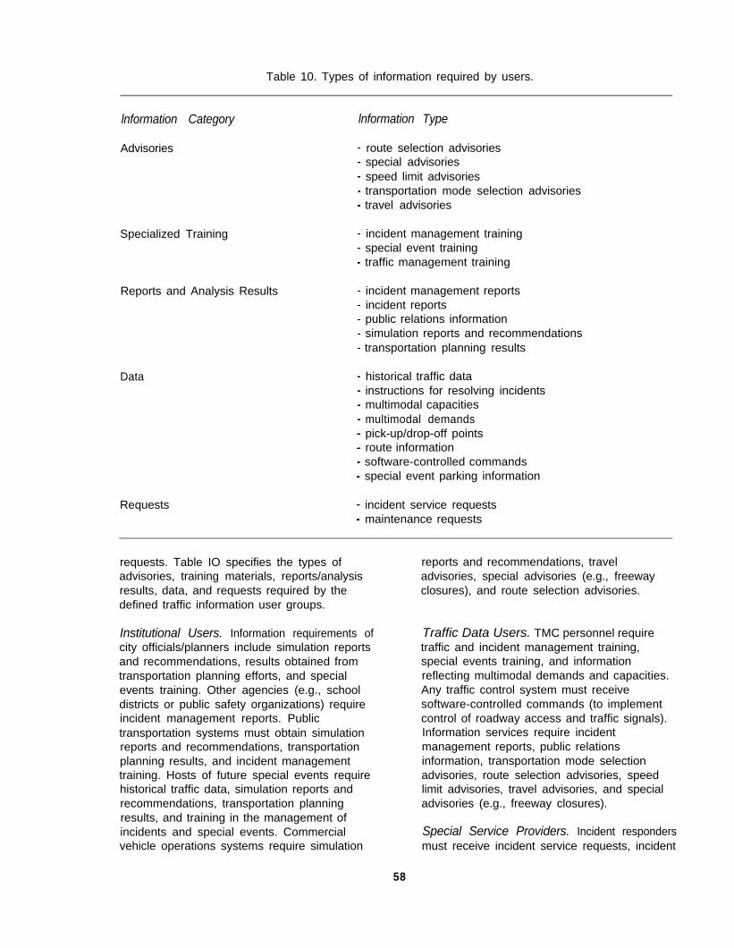
Table 10. Types of information required by users.
lnformation Category lnformation Type
Advisories
Specialized Training
Reports and Analysis Results
Data
Requests
route selection advisoriesspecial advisoriesspeed limit advisoriestransportation mode selection advisoriestravel advisories
incident management trainingspecial event trainingtraffic management training
incident management reportsincident reportspublic relations informationsimulation reports and recommendationstransportation planning results
historical traffic datainstructions for resolving incidentsmultimodal capacitiesmultimodal demandspick-up/drop-off pointsroute informationsoftware-controlled commandsspecial event parking information
incident service requestsmaintenance requests
requests. Table IO specifies the types ofadvisories, training materials, reports/analysisresults, data, and requests required by thedefined traffic information user groups.
Institutional Users. Information requirements ofcity officials/planners include simulation reportsand recommendations, results obtained fromtransportation planning efforts, and specialevents training. Other agencies (e.g., schooldistricts or public safety organizations) requireincident management reports. Publictransportation systems must obtain simulationreports and recommendations, transportationplanning results, and incident managementtraining. Hosts of future special events requirehistorical traffic data, simulation reports andrecommendations, transportation planningresults, and training in the management ofincidents and special events. Commercialvehicle operations systems require simulation
reports and recommendations, traveladvisories, special advisories (e.g., freewayclosures), and route selection advisories.
Traffic Data Users. TMC personnel requiretraffic and incident management training,special events training, and informationreflecting multimodal demands and capacities.Any traffic control system must receivesoftware-controlled commands (to implementcontrol of roadway access and traffic signals).Information services require incidentmanagement reports, public relationsinformation, transportation mode selectionadvisories, route selection advisories, speedlimit advisories, travel advisories, and specialadvisories (e.g., freeway closures).
Special Service Providers. Incident respondersmust receive incident service requests, incident
58
reports, incident management reports, androute information. Maintenance providersreceive maintenance requests. Pre-positionedassets require instructions for resolvingincidents, incident reports, and special eventstraining. Emergency vehicles require routeselection advisories and special advisories.
Public Users. Special event traffic must receivespeed limit advisories, travel advisories,transportation mode selection advisories,special event parking information(location, capacity), and route selection
advisories. Roadway drivers must receive routeselection advisories, speed limit advisories,travel advisories, and special advisories. Thegeneral public requires public relationsinformation, route selection advisories, traveladvisories, and transportation mode selectionadvisories. Operators of public transportationmust receive route selection advisories, speedlimit advisories, travel advisories, and specialadvisories. Commercial vehicle operators (e.g.,taxi drivers, truckers) require route selectionadvisories, speed limit advisories, traveladvisories, special advisories, and pick-up/drop-off points (specific to taxi drivers).
59


SECTION 5OPERATOR TASK ANALYSIS
INTRODUCTION
This section offers our most detailedassessment of operator performance: a taskanalysis. We begin with a set of task analysisobjectives and subsequently discuss the meansby which our research has satisfied eachobjective. A brief description of our taskanalysis methodology is followed by adiscussion of results. Implementation of thetask analysis methodology is demonstratedthrough an example. In this example, the tasksdefined for Function 2.1.1.2 (AnticipateNear-Term Traffic Conditions) are presented.Recognize that no discussion of operator taskperformance would be complete without adiscussion of operator workload. Consequently,this section concludes with such a discussion.
TASK ANALYSIS OBJECTIVES
The primary objectives of the operator taskanalysis are to:
Identify the operator tasks required forsuccessful execution of each ATMSfunction.Ensure that the operator tasksassociated with a given function satisfythe performance requirements imposedby the operator role assigned to thatfunction.Provide an organizational framework(categorization) for operator tasks.Identify significant maintenance tasks.Describe operator tasks in sufficientdetail (and context) to support thepreparation of a human factorsspecification.
A detailed task analysis, the results ofwhich are to follow, identified a total of 363required operator tasks and 485 related tasks.(9) (Related tasks are subtasks of requiredtasks. More detailed definitions of these twotask categories are provided in the discussionfocusing on methodology.) Each ATMSfunction, in addition to being defined in terms ofa four-stage information processing model(input, processing, response selection, output),is represented by a list of operator tasks. Thenature of the tasks assigned to a given function
reflect the demands imposed (on an operator)by that function’s designated operator role. Inthis manner, task analysis objectives one andtwo are satisfied. A good example of the“matching” of task nature to operator role canbe demonstrated through the ExecutiveController functions. Executive Controllerfunctions are fully automated, and operatorshave no control capabilities other than enablingor disabling function execution. Consequently,operators are required to (1) monitor functionoutput, (2) determine if a function disable(enable) is required, and if necessary, (3)disable (enable) the function. All ExecutiveController functions are characterized by thissequence of tasks.
Our task analysis also yielded anorganizational framework for operator tasks,where each task was assigned to one of sixcategories. These task categories arecommunications, coordination, decision-ma king,information processing, observation, andoutcome. Appendix E lists the 363 requiredoperator tasks, and Appendix F lists the 485related tasks according to these categories,satisfying task analysis objective three.
ATMS functionality supports a range ofmaintenance capabilities, and from thesemaintenance functions, we can derive a set ofmaintenance-related operator tasks. A total of10 ATMS functions are based on maintenancecapabilities. These functions are listed below:
Function 1.1.2.2.1. Receive BIT ReportsFunction 1.1.2.2.2. Receive Ad Hoc
Component Status ReportsFunction 2.2.2.1. Determine Remedial
Maintenance NeedsFunction 2.2.2.2. Determine Preventive
Maintenance NeedsFunction 2.2.3.1. Determine Software Upgrade
NeedsFunction 2.2.3.2. Determine Hardware
Upgrade NeedsFunction 3.2.1.1. Transmit Electronic
Maintenance RequestsFunction 3.2.1.2. Issue Special Maintenance
RequestsFunction 3.2.2. Issue Upgrade
61

RequestsFunction 4.2.2. Provide Maintainer Training
Note that maintenance activities aredistributed across all four function types: inputfunctions (1.1.2.2.1 and 1.1.2.2.2), throughputfunctions (2.2.2.1, 2.2.2.2, 2.2.3.1, and 2.2.3.2),output functions (3.2.1.1, 3.2.1.2, and 3.2.2),and support functions (4.2.2). Results of themost detailed analysis of maintenance tasksare to follow, and a summary of maintenancetasks is presented in appendix G. Throughthese analysis results and the task summarypresented in appendix G, task analysisobjective four is satisfied.
The authors of reference 9 accompany thetask list defined for each ATMS function with adetailed task description. The intent of such adescription, together with its respective task list,is to provide sufficient context to supportpreparation of the human factors specificationfor TMC configuration items (task analysisobjective five). Reference 10 documents thehuman factors specification.
METHODOLOGY: OPERATOR TASKANALYSIS
Here, the methodology employed in thederivation of operator tasks is presented. Thetask analyses conducted as a result of thisresearch effort were of an analytical nature andwere performed by a team of human factorsspecialists. A two-phased analysis wasconducted.
Phase One
In the initial phase, a context-free taskanalysis was conducted. That is, each functionwas assessed solely in terms of its designatedoperator role and information processing modeldescription. From this description, a set ofoperator activities and responsibilities wasderived. Note that a function’s role designation,as well as the levels of automation (levels ofoperator involvement) assigned to itsinformation processing stages, motivated thekinds of tasks derived for that function. Fullyautomated functions, for example, require anoperator to monitor (oversee) functionexecution, rather than to take directresponsibility for function execution.
Once the operator activities were derived, theywere assigned to one of two categories of tasktype. These categories are referred to asrequired tasks and related tasks. Requiredtasks represent a core set of activities theoperator must perform in order for successfulexecution of the associated function. In otherwords, when a given function is executed, anoperator performs all of the required tasksassociated with that function. Required tasksalso represent a high level set of activities.This reference to high level activities hasparticular meaning when one considers thesecond category of task type: related tasks.
Related tasks are subtasks of requiredtasks. They are performed during the course ofthe operator’s completion of required tasks. Inessence, related tasks support completion ofrequired (high level) tasks. A related task maybe unique to a given function, or it may appearas a related task in more than one function. Insome instances, related tasks are requiredtasks of other functions. Note that completionof all related tasks associated with a givenfunction may not be required for successfulexecution of that function. Execution of thefunction may require completion of only asubset of related tasks. This particular operatorperformance requirement (i.e., completion ofrelated task subsets) has the followingimplication: The context in which a function isexecuted will determine the related tasks thatare appropriate for completion of that function.
The initial phase of this task analysis alsoyielded a task description. This descriptionprovides an overview, a global perspective, ofthe required operator tasks. The taskdescription serves as an introduction to the listof required tasks.
Phase Two
Phase two of the task analysis validatedthe results of our context-free analysis. Duringphase two, each of the four reference scenariosdocumented in reference 5 was analyzedaccording to operator tasks, where this analysiswas anchored to the scenario’s milestones.Note that each milestone is associated with aset of functions, and in turn, each function isassociated with the tasks derived in phase one.Thus, the scenarios were used as a means ofapplying the results obtained in phase one.
62
The scenarios also enabled us to impose asense of context onto the task analysis, andconsequently, a number of tasks (unidentified inthe context-free analysis) were recognized oncetheir respective functions were placed within thecontext of a traffic scenario. Any newlyidentified operator task (for a given function)was assigned to the list of required tasks or tothe list of related tasks specified during phaseone. If the new task represented a high level(core) task, it was assigned to the list ofrequired tasks; however, if the new taskrepresented a subtask, it was assigned to thelist of related tasks. Thus, the results obtainedfrom each scenario task analysis enabled us toupdate (in an iterative fashion) our required andrelated tasks.
Scenario task analyses were of ananalytical nature and were performed by ateam of human factors specialists. In summary,the task analysis results to follow represent theoutcome of the two-phased process.
TASK ANALYSIS RESULTS
Each ATMS function was analyzed in termsof the operator tasks associated with successfulexecution of that particular function. In thisanalysis, a given task was assigned to one oftwo categories: required task or related task.Required tasks represent a core set of activitiesthe operator must perform in order forsuccessful execution of the respective function.In other words, when a given function isexecuted, an operator performs all of therequired tasks assigned to that function.Required tasks also represent a high level setof activities.
An assessment of all operator tasks(required and related) enabled us to establishsix categories of task type: communicationstasks, coordination tasks, decision-makingtasks, information processing tasks, observationtasks, and outcome tasks. Each required andrelated task was assigned to one of these sixtask types. Appendixes E and F provide theresults of this assignment exercise, whererequired tasks (appendix E) and related tasks(appendix F) are listed according to task type.Note that maintenance-related tasks appear inboldface type.
Communications tasks represent thoseactivities that require TMC operators to receiveand transmit information, where this informationarrives from (and is distributed to) internal andexternal sources. Communications tasksencompass the following actions: distribute,exchange, initiate, issue, provide, receive,report, transmit (and retransmit).
Coordination tasks reflect activitiesrequiring the TMC operators to plan, formulatestrategies, and cooperate with other individualsor agencies that may be internal or external tothe TMC. Coordination tasks encompass thefollowing actions: conduct, continue, initiate,maintain, acknowledge, comment on, conformto, designate, interact with, share.
Decision-making tasks suggest activitiesthat are performed as a result of reasoningstrategies or cognitive processing implementedby the TMC operator. Decision-making tasksare performed once the operator recognizesthat (1) the ATMS is awaiting a response or (2)intervention of ongoing system functions isnecessary. Decision-making tasks incorporatethe following actions: determine, enter,implement, interact with, modify, override.
Information processing tasks require theoperator to analyze incoming information suchthat some form of reasoning strategy isimplemented. These tasks encompass thefollowing actions: assess (and reassess),assimilate, compare, evaluate, review, select
Observation tasks involve the TMCoperator’s ability to oversee (and manage)ATMS events, where such events may beanticipated or unanticipated. The followingactions are associated with observation tasks:confirm, detect, ensure, identify, monitor,recognize, validate, verify.
Outcome tasks represent end products.Typically (within the context of ATMS activities),end products are analysis results. Theoperator’s performance of outcome tasksensures that these results are conveyed. Suchtasks characterize the types of end productsgenerated from traffic management activities.The following actions are associated withoutcome tasks: create, develop, devise,establish, formulate, manipulate, prioritize (andreprioritize), program, reassign, recommend,
63
retrieve, simulate, specify, store, update, write.
Our task analysis identified a total of 363required tasks and 485 related tasks. Requiredoperator tasks were distributed in the followingmanner: 116 communications tasks (32percent), 7 coordination tasks (2 percent), 22decision-making tasks (6 percent), 46information processing tasks (13 percent), 125observation tasks (34 percent), and 47 outcometasks (13 percent). Related operator taskswere distributed in the following manner: 154communications tasks (32 percent), 29coordination tasks (6 percent), 25decision-making tasks (5 percent), 56information processing tasks (11 percent), 113observation tasks (24 percent), and 108outcome tasks (22 percent).
Results of the task analysis suggest thatthe configuration of human and machinecomponents assigned across the fourprocessing stages of a given function willenable us to predict the general nature of thetasks specified for that function. Consider, forexample, fully automated (executive controller)functions. In such functions, rather thanexecuting a given activity, an operator monitorsmachine-execution of that activity.
Maintenance Tasks
ATMS functionality encompasses a numberof maintenance-related responsibilities. A totalof IO lowest-level ATMS functions reflectrequirements for maintenance activities. Ofthese IO functions, 8 are subfunctions of 4higher order maintenance functions. Thesefour high level functions are Function 1.1.2.2:Sense Electronic Component Status, Function2.2.2: Determine Maintenance Needs, Function2.2.3: Determine Upgrade Needs, and Function3.2.1: Issue Maintenance Requests. The eightmaintenance subfunctions corresponding to thisset of higher order functions, as well as eachsubfunction’s designated operator role, areprovided below.
Function 1.1.2.2. Sense Electronic ComponentStatusFunction 1.1.2.2.1. Receive BIT Reports
(Executive Controller)Function 1.1.2.2.2. Receive Ad Hoc
Component Status Reports (DirectPerformer)
Function 2.2.2. Determine Maintenance NeedsFunction 2.2.2.1. Determine Remedial
Maintenance Needs (SupervisoryController)
Function 2.2.2.2. Determine PreventiveMaintenance Needs (SupervisoryController)
Function 2.2.3. Determine Upgrade NeedsFunction 2.2.3.1. Determine Software
Upgrade Needs (Direct Performer)Function 2.2.3.2. Determine Hardware
Upgrade Needs (Direct Performer)
Function 3.2.1. Issue Maintenance RequestsFunction 3.2.1.1. Transmit Electronic
Maintenance Requests (ExecutiveController)
Function 3.2.1.2. Issue SpecialMaintenance Requests (ManualController)
The two remaining maintenance functions andtheir respective operator roles are providedbelow.
Function 3.2.2. Issue Upgrade Requests(Direct Performer)
Function 4.2.2. Provide Maintainer Training(Manual Controller)
A summary of all required maintenancetasks is provided in appendix G. A total of 47maintenance tasks (i.e., 13 percent of allrequired operator tasks) are specified. Notethat the percentage of required maintenancetasks is approximately equal to the proportionof maintenance functions derived as a result ofthe function analysis reported in reference 13.That is, 10 of 113 functions (9 percent) wererelated to maintenance functionality.
Note that ATMS functionality does notencompass maintenance activities directlyrelated to the repair of components in the field.Rather, the ATMS focuses on (1) receivingadequate levels of information on currentconditions such that data reflecting systemdegradations and malfunctioning componentsare available, (2) identifying maintenance needsin a timely manner, (3) issuing maintenancerequests to the appropriate set of serviceproviders, and (4) conducting maintenancetraining. These functional requirements werederived in response to the guidance we
64

received from our IVHS experts. (11) Onefeature of the ATMS environment that guidedfunctional development toward the overseeingof maintenance activities, rather than the actualimplementation of such activities, is reiterated inthe following statement.
“Multiple political jurisdictions comprise thearea served by the ATMS, including a largecentral city plus smaller surrounding cities, andscattered unincorporated areas under thecontrol of the various counties in themetropolitan area.” (11,page7)
Due to the various political boundaries overwhich the ATMS is likely to operate, our IVHSexperts considered maintenanceimplementation issues to be most appropriatelyaddressed by individual localities.Consequently, such issues are not included inthe existing ATMS functionality derivation.
Required maintenance activities aredistributed across all task categories in thefollowing manner: 17 communications tasks, 1coordination task, 3 decision-making tasks, 2information processing tasks, 17 observationtasks, 7 outcome tasks. The majority ofmaintenance-related activity (72 percent) isdedicated to receiving component status data,receiving system upgrade information(hardware as well as software upgrade data),issuing maintenance requests, and overseeing(recognizing, identifying) maintenance needs.To a lesser, but not insignificant, degree (15percent), operator tasks focus on the results(outcomes) of various maintenance analyses(e.g., the prioritization of maintenancerequirements, the development of maintainertraining materials, and the prioritization ofhardware/software procurement efforts).
Fifty-six of the 485 related tasks specifiedin appendix F (i.e., 12 percent of all relatedtasks) reflect maintenance activities. Thesetasks appear in boldface type. Of these 56tasks, the following distribution of taskcategories is apparent: 26 communicationstasks (46 percent), 3 coordination tasks (5percent), 2 decision-making tasks (4 percent), 4information processing tasks (7 percent), 15observation tasks (27 percent), and 6 outcometasks (11 percent). Once again, the majority ofmaintenance activity (among the related tasks)is assigned to communications and observation
responsibilities (73 percent). Furthermore, sixof all related maintenance tasks (11 percent)focus on outcomes.
These distributions of maintenance tasksdo indeed reflect the maintenance focussuggested by our IVHS experts.
Task Analysis Example
Consider once again Function 2.1.1.2:Anticipate Near-Term Traffic Conditions.(Recall that in Section 3 this function was usedto demonstrate the function allocationmethodology.) The task description establishedfor Function 2.1.1.2, as well as the requiredand related tasks derived from implementationof the two-phased task analysis approach, areprovided in the example to follow.
Example
Function 2.1.1.2: Anticipate Near-Term TrafficConditions
Operator Role: Supervisory Controller
Task Description: Current load assessmentsand roadway status reports are reviewed. Inputdata are processed via a near-term trafficmodel, and inaccuracies are identified andmodified. Predictions are recorded. Ifnecessary, traffic predictions are overridden.
Required Tasks: monitor near-term trafficpredictions (traffic volumes, densities, speeds),identify predictions that must be overridden(inaccuracies imprecision), determinealternative predictions, modify input information(if necessary), override traffic predictions (ifnecessary)
Related Tasks: monitor traffic predictioninformation, monitor input information (currentload assessment, current roadway systemstatus, external report information), validateinput information, identify invalid inputinformation, monitor traffic control information
DISCUSSION OF OPERATOR WORKLOAD
The term workload refers to the cognitive,as well as physical, demands placed on anoperator as a function of task performance.
65

Consider the nature of ATMS operator tasks(as characterized by the categories establishedas a result of this research effort --communications, coordination, decision-ma king,information processing, observation, andoutcome). Within the context of the ATMSenvironment, an assessment of mentalworkload has more relevance than one ofphysical workload.
According to Gopher and Donchin,workload characterizes the interaction betweenan operator and a given task?(15) Specifically,any task is performed with respect to specifiedstructural features. That is, the task is definedin terms of stimuli and responses, where a setof rules defines the manner in which stimuli aremapped to responses. Additionally,expectations regarding the quality of operatortask performance are important. Expectationsof task performance quality are derived fromour knowledge of the relationship between taskstructure (the rules mapping stimuli toresponses) and human capabilities and skills.Expectations may also be based on ourknowledge of operators’ previous performanceor on our knowledge of operators’ performanceof similar tasks. In some cases (even undercircumstances in which an operator issufficiently motivated to perform a given set oftasks and intends to perform these tasksaccording to the expected standards) theestablished expectations are not satisfied.Such performance failures can be attributed toincreased task difficulty or to limitations inattentional resources. Workload assessmentrepresents an attempt to explain theseperformance failures.
Current interpretation of the mentalworkload concept suggests the existence oflimitations in operators’ abilities to processinformation. Given a target task and thepotential for such limitations to be realized, anoperator may find his information processingcapabilities ineffectual in performing the targettask. One assumption associated with taskperformance is described as follows. Taskperformance is dependent upon effectors(through which responses are made) andsensors (through which stimuli are intercepted).The path from sensors to effectors isrepresented via a complex informationprocessing “structure.” Associated with thisstructure are various properties, one of them
being a limited capacity. Thus, mentalworkload may be defined as the differencebetween two quantities: the capacity that isrequired to ensure expected task performanceand the capacity available at any given time. Inother words,
where
W = mental workload (2)Crequired = required capacity (3)C available = available capacity. (4)
Task difficulty and attentional resourcelimitations are manifested by a differencebetween expected and actual performance.
According to Meister, workload can beimposed in a number of ways.(16) At the input ofa system, workload may be imposed by stimulithat drain attentional resources and load anoperator, causing that operator to perceive aburden. Workload is also defined in terms ofthe internal sense of difficulty and discomfortexperienced by an operator. Note thatworkload is detected only when the operatorrecognizes difficulty and discomfort andsubsequently formulates a strategy to overcomethe burden. At the output of a system,workload affects not only operator performancebut system performance as well. Meistercharacterizes workload in the followingmanner?
l System feature forcing an operator towork harder.
l Perception of stress (on the part of theoperator).
l Recognition (on the part of the operator)of the requirement to work harder.
l Operator errors occurring as a result ofstress and increased work effort.
Recognize that workload (imposed as aresult of operator-task interaction) is ofrelevance only within the context of adesignated set of events. That is, assigning aworkload rating to an isolated task (withoutconsidering the environmental conditions thatmay affect task performance) is somewhatmeaningless. Within the bounds of our ATMSresearch, contextual information is afforded bythe four second-generation scenarios. Results
66

of our scenario task analysis suggest thefollowing: If we assume a single-operator TMC,the single operator will experience aninordinately high level of workload. Workloadcan be reduced with the introduction ofadditional operators. At this stage of ourresearch, however, the optimal number ofoperators is unknown. Consequently, asresearchers, we believe that an accurateassessment of workload can be conducted onlywhen empirical results from a detailed analysisof job design, job allocation, and teamperformance, (i.e., results from an analysis ofmultiple-operator TMC’s) are available. TheTMC simulator experiments described inreference 17 will address issues of job designand allocation, as well as team performance,and are intended to yield assessments ofworkload.
A proposed approach for conducting aninitial assessment of workload was to considereach task (as it appears within the context of agiven scenario) and assign a performance time
to that task. Recall that scenario events arespecified according to a set of milestones(timeline events). Our initial approach was toconsider consecutive milestones (Mx and Mx+1)and calculate the time difference betweenthem. In this manner, we could establish timeconstraints for a given set of operator tasks.That is, the tasks performed between Mx andMx+1 would be completed during the timewindow Mx+1-Mx. Once our analysis began,however, we determined that a given milestoneonly suggests the time at which its respectiveset of tasks must begin; it does not necessarilyindicate the end point of task performance. Inother words, task performance might extendbeyond an Mx+1 milestone. Given suchconditions, our alternative was to estimate taskperformance times. With no available empiricalor expert data to guide us, such an approachappeared to be ad hoc at best and unscientificin general. Consequently, our intent is to relyon empirical data obtained from the TMCsimulator experiments to provide moremeaningful evaluations of operator workload!‘)
67

SECTION 6.HUMAN FACTORS SPECIFICATION
INTRODUCTION
This section presents a human factorsspecification developed for the ATMS. (10)
Development of a human factors specificationrepresents the sixth and final step of the top-down system analysis process. In general, anyhuman factors specification is driven byanalyses of operator performance requirementsand operator tasks (Steps 4 and 5 of the top-down system analysis). Furthermore, resultsobtained from these analyses of the humanoperator are driven by the function allocationprocess (Step 3 of the top-down systemanalysis).
The human factors specification developedfor the ATMS was no exception. That is,results of the function allocation processenabled us to define appropriate operatorperformance requirements and operator tasksfor each ATMS function. Specifically, taskanalysis results suggest that the configurationof human and machine components assignedacross the four processing stages of a givenfunction (i.e., the manner in which human andmachine components are allocated to a givenfunction) will enable us to predict the generalnature of the operator tasks specified for thatfunction. Consider, for example, fullyautomated (executive controller) functions. Insuch functions, rather than executing a givenactivity, an operator only monitors machine-execution of that activity. Consequently, tasksdefined for executive controller functions reflectthis form of human-ATMS interaction.
In defining ATMS functionality, completingthe function allocation process, and then in turnconducting analyses specific to the humanoperator, we considered the following question.Through what means will ATMS functionality beexecuted? That is, what machines, apparatus,or devices will facilitate the satisfactoryexecution of ATMS functions? In addressingthe issue of function execution, we defined aset of support systems. Consequently, supportsystems represent the means by which ATMSfunctionality is executed. In general, a supportsystem is a tool (hardware and/or software)through which an operator interacts in order to
ensure that ATMS functions are satisfactorilyexecuted.
Our initial support systems analysis yieldeda set of nine idealized (conceptual) supportsystems. (5) Capabilities required for thefollowing support systems were defined:
Adaptive Traffic Control System (ATCS).Predictive Traffic Modeling System(PTMS).Incident Detection and Location System(IDLS).Incident Response and Advisory System(IRAS).Information Dissemination System (IDS).Intermodal Transportation Planning System(ITPS).Traffic Management Training System(TMTS).Maintenance Tracking System (MTS).Traffic Data Management System (TDMS).
Based on further analyses of operatorperformance requirements, we identified theneed for three additional support systems.Capabilities required for these support systemswere defined: (8)
l Communications Support System (CSS).l Administrative Support System (ADSS).l Maintainer Training Support System
(MTSS).
The resulting 12 support systems (and thecapabilities assigned to each system) provide amechanism by which all 113 ATMS functionscan be executed. In other words, these 12support systems reflect (completely) ATMSfunctionality. Note that the capabilitiesanalyses documented in references 5 and 8focused on idealized support systems, wherethe capabilities of such systems are conceptualin nature. In other words, the capabilitiesassigned to a given idealized support systemserve as a model for those ultimatelyimplemented and incorporated in an operationalATMS.
In developing the ATMS human factorsspecification, we first defined the capabilitiesappropriate for each of the 12 support systems
69
and then established a set of human interfacerequirements for each system. (10) Each set ofinterface requirements identified and describedthe information to be provided to the systemby operators. Associated with the supportsystems is a set of hardware configurationitems used by operators for voice and textcommunication, information/data collection,information processing, and data archiving.Some of these configuration items representstand-alone systems (e.g., electronic mail or faxsystems), while other items are incorporatedinto a given multipurpose system, where such asystem is typically computer based.
In the following subsection, the humanfactors specification derived for each supportsystem is documented. The specificationderived for a given support system includes adetailed description of the system’s capabilities,as well as results of the human interfacerequirements analysis conducted for thatsystem. Following our analysis of supportsystem capabilities and interface requirementsis a discussion of the hardware configurationitems associated with the support systems.Note that by developing the human factorsspecification such that it focuses on the supportsystems, we ensure that the specificationreflects all functional characteristics of theATMS, as well as the operator performancerequirements and operator tasks defined byATMS functionality.
SUPPORT SYSTEMS
In this subsection the capabilities andinterface requirements derived for each supportsystem are presented. System capabilities areanalyzed with respect to global functionality, aswell as specific activities. (9) The list of activitiesaccompanying each system’s global descriptionis not intended to be exhaustive. Rather, itintroduces the reader to the duties assigned toa support system and the types of informationto which ATMS operators will be exposed.Each capabilities analysis suggests (1) thenature (and format) of the information anoperator receives, (2) the range of decisions anoperator must make (including the types ofevents the operator must resolve), and (3) theresponses (outputs) required of an operator.The intent of the capabilities descriptions is notto specify an implementation strategy but to
specify a set of attributes and activities webelieve are appropriate for futureimplementations. The interface requirementsderived for each support system identify anddescribe the information displayed to operatorsvia the support system interface, as well asinformation to be provided to the system byoperators.
Adaptive Traffic Control System (ATCS)
System Capabilities
The ATCS will optimize current traffic flow.It will receive roadway sensor data and use it tocontrol traffic signal timing and ramp metering.The ATCS will maintain optimal flow byautomatically responding to current traffic. Akey feature will be the ability of the ATCS tointegrate control across surface streets andfreeway traffic. When, for example, ramp metercycle times are increased to dampen flow ontoa freeway, traffic signal cycle times atintersections feeding the freeway ramp areadjusted appropriately. The algorithms used bythe ATCS will be sufficiently robust toautomatically accommodate unusual trafficpatterns (e.g., special event patterns). TheATCS will be assigned the responsibility ofmaking low-risk “predictions,” where any trafficcondition forecasts provided by the ATCS havea low risk of being inaccurate. Controlstrategies to be implemented by the ATCSrequire neither operator review nor approval.Rather than describe the ATCS’s look-aheadcapabilities as predictive, we suggest that theATCS only anticipates near-term trafficconditions (c. 1 to 5 min). ATCS activitiesinclude the following:
l Anticipate near-term traffic conditions.l Coordinate passage of rail vehicles.l Determine roadway access control measures
required by an optimal control scheme.l Implement traffic control options.l Receive “best” traffic control option.l Receive current road conditions.l Receive current traffic conditions.l Receive ATMS responsibilities in responding
to/managing incidents.l Receive predicted road conditions.l Receive predicted traffic conditions.l Receive recommended level of ATMS support
for special vehicles.l Request network data.l Request roadway sensor data.
70
Specify traffic signal timing sequencesrequired by an optimal control scheme.Specify traffic signal timing sequencesrequired by incident response approaches.Support development of feasible incidentresponse strategies.Translate control measures into commandsissued to control devices.
Human Interface Requirements
The ATCS will be assigned theresponsibility of making low risk predictions. Inother words, traffic condition forecasts providedby the ATCS will have a low probability ofinaccuracy. The ATCS will typically implementcontrol strategies without operator review orapproval. Operators will be provided thecapability to review currently implementedstrategies on an intersection-by-intersectionbasis via a signal status display.Multi-intersection signal status displays(employing appropriate icons and color coding)will enable operators to review wider regions ofthe network.
The operator can disable the ATCS ifineffective or erroneous control actions areimplemented. Once the ATCS is disabled,traffic signal timing plans will default topredefined demand or time-of-day strategies.An “error trap” will be incorporated in theprocess for disabling the ATCS such that (atleast) a two-step sequence will be required. Inmost instances, the Predictive Traffic ModelingSystem (PTMS) will recognize when ATCSresponses are inappropriate and must beoverridden. Once ATCS control actions aredisabled or overridden by the PTMS, amessage to that effect will be conspicuouslydisplayed on the operator’s primary displays.
Operators will be provided limited access tothe direct control of individual intersectioncontrollers (e.g., creating a “green wave” ofsignals for emergency vehicles). Operatorfunctions will be implemented via keyboard ormouse input devices.
Predictive Traffic Modeling System (PTMS)
System Capabilities
The PTMS will use current data, historicaldata, and weather forecasts to predict traffic
flow a few minutes into the future (c. 5 to 30min). PTMS predictions will allow preemptiveactions to be taken well before an actual trafficproblem arises. The following current data willbe used by the PTMS: traffic data, data fromroadway surface condition and visibilitysensors, O-D data from vehicles currentlytraveling the roadway system, and incidentdata. Historical data will include time-of-dayand day-of-week profiles, appropriately adjustedfor special conditions (e.g., inclement weatherand special events). Ramp metering and trafficsignal timing patterns currently implemented bythe ATCS will be used in making predictions.Predictions will also consider existing ATMSadvisories. For instance, the PTMS will predictthe percentage of people taking an alternateroute once it is suggested on a variablemessage sign (VMS), and use this prediction inforecasting future traffic conditions. The PTMSwill also be used to predict the effects ofchanges in traffic control timing patterns and ofchanges in advisories issued by the ATMS.Thus, it will be used to evaluate candidatetraffic management techniques in unusualconditions (a what if capability) such as thosegenerated by the presence of a major incident.Knowing what control strategy the ATCS willimplement in response to a given trafficcondition, the PTMS will recognize when thatresponse must be modified. PTMS forecastswill have a higher risk of being inaccurate thanforecasts provided by the ATCS.Consequently, any recommendations thatsuggest how the ATMS should respond toPTMS predictions must be reviewed andapproved by an operator. PTMS activitiesinclude the following:
l
l
l
l
l
l
l
l
l
l
l
l
Assess incident data (negative impact ontraffic flow).Assess quality of a control option.Assess weather pattern’s impact on trafficflow.Assess weather service data.Assess effectiveness of traffic managementstrategies.Conduct tactical traffic planning.Derive control option scores.Perform near-term simulations.Predict traffic conditions given options.Predict rail traffic location.Prioritize control options.Prioritize rail traffic information (assessnegative impact on traffic flow).
71

l Prioritize roadway conditions (assess negativeimpact on traffic flow).
l Receive traffic control options currently ineffect.
l Request incident data.l Request network data.l Request O-D data.l Request roadway sensor data.l Track special vehicles.
Human Interface Requirements
The PTMS will serve as a decision aid fromwhich operators are to obtain information onpredicted traffic flows. (Decisions related tocontrol actions and information disseminationoptions are to be reached.) Information will bepresented via a color coded roadway map attwo levels of detail: a large-scale presentationof the entire roadway network or a detailed(“zoomed-in”) presentation of a 13 to 26 km2 (5to 10 mi2) region of the network. PTMSpredictions will be conspicuously identified assuch in order to preclude confusion with actualtraffic data.
Operators will have the ability to reviewpredictions of 5, 10, 15, 20, or 30 min into thefuture. An option for rapid display of thesepredictions (in sequence) will be provided. Thisoption will enable operators to visualizeprojected changes in traffic flow patterns as afunction of time. A menu-based interface willenable operators to initiate this sequencing ofpredictions.
The PTMS will also have the ability tooperate in a simulation mode. In this modesimulations of traffic conditions, indicating themanner in which traffic can be expected torespond to a range of candidate inputconditions, are performed (a what if mode).Note that the PTMS will have a parallelprocessing capability. Such a capability willenable the PTMS to continue its predictionactivities while it conducts simulationsrequested by an operator. In other words,routine prediction capabilities are notsuspended when the PTMS is placed in itssimulation mode. Most important, the operatorwill have ready access to ongoing predictions(that rely on current traffic flow measures,incident parameters, ramp meter and signaltiming plans, and VMS/HAR advisories)independent of the support system’s current
mode of operation. The PTMS will be placed inits simulation mode via a menu command.Subsequently, operators will enter allinformation required by the simulation (e.g.,timing plan changes and advisory changes) viamenu and keyboard inputs. Operators musthave the option of recording simulation results.A single menu entry will terminate thesimulation mode and enable the operator toview information solely associated with theprediction mode.
Information presented during each of thetwo operating modes (prediction mode versussimulation mode) must be clearlydistinguishable. Operators will have access topredicted traffic conditions and simulationresults. Both types of information are to bedisplayed. Consequently, the potential foroperators to confuse existing/projected trafficconditions and simulated conditions must notexist.
The PTMS will have complete knowledge ofthe control strategy repertoire available to theATCS. Furthermore, the PTMS will haveknowledge of the control strategy to beimplemented by the ATCS in response to giventraffic conditions, and will recognize when thatresponse must be adjusted. The operator mustbe aware of those instances in which the PTMSrecognizes the need to override ATCS controlstrategies. Any recommendation that suggestsa TMC response to a given PTMS predictionmust be reviewed and approved by theoperator.
The PTMS may also have a capability toevaluate, recommend, or prioritize TMC actions.The results of such analyses, and the basis forthese outcomes, will be displayed to theoperator for approval, modification, or rejection.Approval/rejection may be implemented viamouse or keyboard commands; modificationmay be implemented via keyboard entry.
Incident Detection and Location System(IDLS)
System Capabilities
The IDLS will receive data from roadwaysensors and from external data links. Itspurpose will be to detect and verify thepresence of incidents on the roadway system
72
and to determine the exact location of anincident. In some cases the first indications ofan incident will be abnormalities in traffic flow inthe immediate area. (Thus, it will identifyanomalies characteristic of a potential incident.)In other cases, especially when traffic volumesare light, the first indications may come fromother sources (e.g., calls from cellular phoneusers) that subsequently result in an entry intoa dispatch data base. Incidents, as defined bythe IDLS, will include system malfunctions (e.g.,traffic signal outages) as well as trafficproblems. Upon detection of a probableincident and determination of its apparentlocation, the IDLS will attempt incidentverification. The IDLS will provide a preliminaryestimate of incident severity (perhaps via asimple color-coding scheme -- yellow or red)based on the data available. The IDLS willhave the capability to learn from experience.IDLS activities include the following:
l Correlate traffic flow data with dispatch andmaintenance information.
l Detect traffic pattern anomalies.l Determine anomaly location.l Determine anomaly source.l Nominate anomaly as a potential incident.l Report anomalies.l Report anomaly location.l Report anomaly source.l Request network data.l Request roadway sensor data.l Request traffic flow data.l Support preparation of incident reports.l Validate incident information.
Human Interface Requirements
The IDLS will alert operators to theoccurrence of potential incidents. Based on thedata it receives from roadway sensors andexternal data links, the IDLS will detect andverify the presence of roadway anomalies. Itwill also determine the exact location of thedetected anomaly. Incidents, as defined by theIDLS, will include system malfunctions (e.g.,traffic signal outages, signal timing phaseproblems), as well as traffic problems (e.g.,major/minor freeway accidents, major/minorsurface street accidents, hazardous waste spill).
A key component of the IDLS will be aroadway map displayed at an operator’sworkstation. Upon initial detection of a potentialincident, the IDLS will alert an operator of its
findings. One means of providing incidentawareness is through a flashing indicator (colorcoded according to the support system’spreliminary estimate of incident severity)displayed on the operator’s map. This type ofindicator, appearing at the anomaly locationdetermined by the IDLS, would serve as aninitial alert. In this manner, an immediateindication of both the existence and location ofa potential incident can be provided.Depending upon resolution (level of detail) ofthe map display, incident location may beimprecise; that is, the map may only indicate ageneral region for the incident.
A more precise specification of incidentlocation must be reported automatically (and inconjunction with the flashing indicator) via aseparate “incident report” display in which thelocation of a potential incident is provided. Inthis manner the detection of a potential incidentis reiterated, and a more precise locationspecification is provided. An audible tone,signaling the presence of a new incident report,would alert the operator to this recent changein traffic conditions. For freeway incidents,location must be specified according to afreeway identifier, heading information(direction), and freeway “coordinates”. Freewaycoordinates may be represented through exitnumbers (e.g., potential incident: l-85 Northbetween exit 8 and exit 9). In some instances,names of interchanges may be moremeaningful (e.g., potential incident: l-85 Northbetween Lenox Road and North Druid HillsRoad). Under these conditions, interchangenames represent an alternative coordinatescheme. Surface street anomalies will bereported in a similar manner, where a streetidentifier, heading information, and streetcoordinates define incident location.
The “incident report” might reinforce thecolor coded information of the flashing indicator(preliminary severity estimate) by displaying aseverity measure. (One such measure revealsroadway blockage: the number of lanes blockedor percentage of the roadway blocked.) The“incident report” display might also be used tospecify a camera or set of cameras that couldprovide views of the incident site. Such viewswould enable the operator to verify theexistence of an incident, obtain more detailedincident information (e.g., anomaly source(hazardous waste spill, equipment malfunction,
73

single vehicle accident, multiple vehiclecollision), types of vehicles involved,existence/status of injuries), and to monitorconditions at the site. Note that not all incidentsites will be afforded an appropriate (useful)camera view, and in such instances, theoperator must rely on other communicationlinks in order to obtain sufficiently detailedinformation (e.g., onsite law enforcementofficers, emergency service providerssummoned to the incident site, passingmotorists).
In some instances, specifically when trafficvolumes are light, the first indications of apotential incident may not arrive via roadwaysensors, but from the communication linkstypically available to the TMC (e.g., reportsfrom cellular phone users, camera views).Under these conditions (i.e., when an “incidentreport” is not automatically generated), theIDLS must facilitate the manual entry of incidentparameters.
Incident Response Advisory System (IRAS)
System Capabilities
The IRAS will assist in determining theappropriate response to an incident. IRASadvice will include options for controlling trafficand disseminating information. Responses toan incident may include (1) informing motoristsof a slight delay, (2) re-routing a portion oftraffic, (3) no action on the part of the ATMS,or, in extreme cases, (4) closing a majorfreeway and re-routing all traffic. In the case oftraffic re-routing, the IRAS will determineoptimal alternate route(s). It maintains thefollowing knowledge: which incident respondersto request for a given type of incident, thedirection from which incident responders willcome, how to direct responders to the incidentsite, whether special support measures will berequired (e.g., closing a downstream exit rampand directing service vehicles to enter theincident scene (from the wrong direction) viathis ramp). The IRAS will learn fromexperience. It will also monitor incidentclearance and assist in determining the point atwhich normal operations should resume. TheIRAS will, for example, determine when to clearan advisory message from a VMS. The IRASwill also provide a simulation capability thatallows evaluation of various response
alternatives. (Under these conditions it will usea version of the PTMS to obtain predictions.This type of simulation will use current trafficdata and must be performed many times fasterthan real time.) IRAS activities include thefollowing:
Assess interagency incident data.Determine appropriate levels of support forspecial vehicles.Identify point at which normal operationsshould resume (detect incident clearance).Formulate incident management report.Formulate incident service requests.Formulate instructions to incident responders.Monitor incident clearance.Receive anomaly detections/locations.Receive incident data.Receive information regarding interactionsbetween rail and roadway vehicles (currentand predicted).Receive interagency incident data.Recommend levels of support for specialvehicles.Support development of feasible incidentresponse strategies.Support formulation of traffic managementresponse (due to rail traffic data).Support ATMS in determining its role inmanaging/responding to an incident.Support preparation of incident managementreports.Support preparation of incident servicerequests.
Human Interface Requirements
The IRAS will support operators inestablishing an appropriate set of incidentresponses. The IRAS will recommend optionsfor controlling traffic (e.g., re-routing traffic,adjusting parameters of signal controllers,defining one-way thoroughfares, closing amajor freeway and subsequently establishingdetours to accommodate the closed freeway)and suggest information appropriate fordissemination to motorists (e.g., informationindicating that motorists will experience a slightdelay, incident severity messages, re-routinginstructions). In some instances the optimalincident response will require no action on thepart of the TMC, and the IRAS will recommendthat no action be initiated. The IRAS alsosupports the timely arrival of appropriateemergency service providers at an incident site.It has knowledge of (1) what incidentresponders to request for an incident of a given

type and severity, (2) the direction from whichincident responders will come, (3) how to directresponders to the incident site, and (4) whetherspecial support measures will be required toensure that incident responders arrive at theincident site.
The primary responsibilities of the IRAS areto support the timely resolution of incidents andto facilitate operator situation awareness asincidents are resolved. Information provided bythe IRAS will be presented through an “incidentresponse” display. This display will recommendtraffic control strategies and indicate the type ofinformation most appropriate for disseminationto motorists. The implementation ofsystem-determined traffic control strategies willnot be contingent upon operator approval;however, the operator will have an overrideoption. (Such a feature will enable specializedor heuristic knowledge acquired by the operatorto be incorporated into the incidentmanagement process.) In situations whereseveral control strategies are appropriate, theIRAS will prioritize them according to astandard criterion (e.g., greatest flow rate) orset of criteria. The most highly ranked strategywill be implemented unless the operatorinitiates an override. For those instances inwhich the operator overrides anIRAS-recommended control strategy, theoperator must have the ability to either selectan alternative strategy (if a lower prioritystrategy is desired) or specify a strategy notrecommended by the system and then executean “implement control strategy” command.
The IRAS may be designed such that thecriteria for ranking traffic control strategies areoperator-specified. That is, the operatordesignates a single criterion (from a list ofpredefined criteria) against which controlstrategies are to be ranked. Another optionmight be for the operator to designate multiplecriteria (rather than a single criterion) againstwhich control strategies are to be ranked.Under this option, final rankings are the resultof a concurrent consideration of the designatedcriteria. Given a feature in which criteria areselectable, the operator might also definemultiple criteria sets, review theIRAS-generated recommendations associatedwith each criteria set, and compare acrossthese recommendations. Note thataccompanying any IRAS recommendation or
prioritized list of recommendations must be aclear indication of the criteria considered indeveloping recommendations.
The IRAS will also provide a simulationfeature through which operators will have anability to predict the outcome of recommendedresponse alternatives. Note that this type ofsimulation will use current traffic data and mustbe performed faster than real time. Simulationswill run in parallel to the response advisoryactivities for which the IRAS is responsible.
The IRAS is responsible for suggesting thetypes of information appropriate fordissemination to operators and for determiningemergency service requirements. Unlessinstructed otherwise, the IRAS will specify theinformation to be disseminated and will initiaterequests for incident service providers. Notethat in performing these activities, the IRASmust interact with the Information DisseminationSystem (IDS).
Because much of the functionality assignedto the IRAS can be performed without operatorapproval (e.g., implementation of recommendedtraffic control strategies, specification ofinformation to be disseminated, requests forincident services), a high level designrequirement for the IRAS's user interface is thatit must maintain an adequate level of operatorsituation awareness. Consequently, the IRASmust facilitate ready access to all incidentstatus information. Such information mightinclude the following:
l The effectiveness of all implemented incidentresponse strategies (traffic control techniquesand information dissemination).
l The effect of recommended responses (i.e.,traffic flow data at the incident site as well asat locations upstream and downstream of thesite).
l Incident status (the degree of progress madein resolving the incident).
l Notification that incident responders (of giventypes) have been dispatched.
l Notification that incident responders (of giventypes) have arrived at the incident site.
l Notification that advisory messages displayedon VMS’s (at given locations) have beenposted, modified, or cleared.
l Notification of incident clearance and a returnto normal traffic flow conditions.
75
With this information the operator will havean ability to monitor the status of incidentclearance procedures.
Note that the IRAS will be required tosupport the management of multiple(simultaneous) incidents. Thus, incidentmanagement and status information associatedwith a given incident must be clearly identifiedas such.
Information Dissemination System (IDS)
System Capabilities
The IDS will interface with establishedcommunication links to response forces such aspolice departments, ambulance services, firedepartments, and towing services. It will alsointerface with data services supplied to (1) themass media, (2) the Traffic Channel, and (3)bulletin board services. The IDS will becapable of posting messages on VMS’s andcreating voice messages for broadcast viahighway advisory radio (HAR). IDS activitiesinclude the following:
Assign/match mode selection advisories toinformation outlets.Assign/match route selection advisories toinformation outlets.Assign/match speed limit advisories toinformation outlets.Assign/match travel advisories to informationoutlets.Broadcast roadway condition report.Broadcast special event report.Download software upgrades to componentsin the field.Issue incident management reports.Issue incident reports.Issue incident service requests.Issue instructions to incident responders.Post mode selection advisories.Post route selection advisories.Post speed limit advisories.Post travel advisories.
Human Interface Requirements
The IDS will interface with establishedcommunication links to a set of responseagencies. These agencies may include lawenforcement offices, emergency medicalservices, fire departments, towing services,maintenance providers, and any other
emergency service providers deemedappropriate (e.g., hazardous waste disposalunits, special crisis management teams). TheIDS will also interface with those data servicesaccessed by (1) the mass media, (2) trafficchannels, and (3) bulletin board services.
A built-in diagnostics capability couldprovide one means of detecting failures atIDS-data service and IDS-communication linkinterfaces. Interface failure reports, if providedto an operator, would notify the operator of theIDS’s inability to interface properly with anestablished communication link(s) and/or adesignated data service(s). Results of thesediagnostic tests would provide the operatoradditional IDS status information and thusenhance situation awareness. Note that aheightened sense of situation awareness is aparticular advantage under conditions of highoperator workload (e.g., the occurrence of amajor incident or a serious weather situation).Certain tests may be running continuously inthe background, and for these tests, anydetected failures (and an identification of theirrespective tests) should be automaticallyreported to the operator when they aredetected. Other tests may require a specificoperator-initiation. In both cases the operatorshould have access to status information.
IDS responsibilities will include the postingof VMS messages and the creation of voicemessages for broadcast via highway advisoryradio. The IDS will be notified by other supportsystems, namely the IRAS and theMaintenance Tracking System (MTS), of aposting requirement. The type of information tobe posted, in addition to the location of itsdesignated VMS(s), will be specified. The IDSwill retrieve appropriate messages from a database of messages and issue “post message”commands. Such commands will initiate themessage posting process. The IDS will alsofacilitate operators’ access to historical recordsof all message-posting activities (i.e., messagesposted, message locations, status of messages(currently posted, cleared, modified), andmessage time stamps). Note that a number oftime stamps can be associated with a givenmessage: time at which message is posted,time at which message is cleared, time of mostrecent modification.
76

In some instances the operator may berequired to initiate a “post message” command,independently of support system instructions ofthis nature. A straightforward manner in whichto facilitate this type of user activity is desirable.One means of providing an operator-initiated“post message” option might be to allow theoperator to select the required message from apredefined list (a menu list) of standard VMSmessages. In other words the IDS would bedesigned with an established repertoire ofmessages from which operators could select.Most likely, messages will be assigned afilename (identifier). Filenames should facilitateeasy recognition of message contents;however, a “read” option would allow theoperator to review message contents forappropriateness. The operator may berequired to compose a VMS message, ratherthan select a predefined message. Underthese conditions, the IDS could provide atemplate enabling the operator to compose anew message appropriate for a previouslyunspecified traffic condition.
The IDS must also provide a means forcreating voice messages to be broadcast viahighway advisory radio (HAR). Thisrequirement suggests a “digitize message”command in which predefined messages(stored in the message data base), as well asoperator-composed messages, could bedigitized and either transmitted for immediatebroadcast or stored for broadcast at some latertime.
Intermodal Transportation Planning System(ITPS)
System Capabilities
The ITPS will supply the simulationcapability to support strategic planning for theATMS. It will, for example, have the capabilityto simulate different configurations of roadwaysystems. Its simulation capability will alsosupport coordinated strategic planning(performed in conjunction with publictransportation systems) and special eventplanning. ITPS activities include the following:
l Assess multimodal demand predictions.l Assess traffic management effectiveness.l Assimilate/compile alternate transportation
mode data.
l Conduct strategic simulations.l Maintain simulation results.l Receive alternate transportation mode data.l Receive interagency special event information.l Receive weather service information.l Recommend multimodal demand regulation
strategy.l Support development of transportation plans.l Support formulation of responses to public
comments (transportation planning issues).
Human Interface Requirements
Through its simulation capabilities, the ITPSsupports strategic planning. Note that thesimulation capabilities of the ITPS are distinctfrom those available within the PTMS andIRAS. Simulations conducted from within thePTMS and IRAS are based on current trafficdata and existing roadway conditions/configurations; additionally, they are conductedin parallel to ongoing traffic and incidentmanagement activities. Because PTMS andIRAS simulation results are intended to supporttraffic and incident management, they must beavailable within a “faster than real time” timewindow. ITPS simulations, on the other hand,represent a more general, less specializedsimulation capability than do the simulationsperformed by the PTMS or the IRAS.
ITPS simulations will be performed insupport of strategic planning exercises, andbecause “faster than real time” results are notas critical to strategic planning activities as theytypically are to traffic and incident managementactivities, such stringent time constraints can berelaxed. Four primary simulation capabilitiesare required in the support of strategicplanning: a capability enabling planners tosimulate roadway system configurations thatare currently nonexistent, a capabilitysupportive of coordinated strategic planning, acapability enabling planners to simulateanticipated special events, and a capability thatwill enable planners to simulate rare (butcritical) emergency situations. Examples ofroadway system configurations include aplanned sports arena, the extension of anexisting Interstate highway, the constructionand eventual addition of a tollway, or theaddition of a major shopping complex. Ifalternate sites for a given configuration areunder consideration, simulation analyses couldfocus on the identification of an optimal site.
77
Coordinated strategic planning might yield (1) aset of routes for all modes of publictransportation, (2) public transportationschedules that are based on projectedmultimodal demands, or (3) a recommendationon the modes of public transportation that aremost appropriate and cost effective for a givenregion. Special event planning provides themeans for operators to anticipate trafficconditions that are likely to occur as a result ofa major sporting event, a concert, a parade ormotorcade, or visits made by national/international dignitaries. Emergency situationsmight include a severe winter storm, ahazardous waste spill, a terrorist attack, or amajor incident.
Given a range of simulation capabilities,operators must be provided the ability tospecify a simulation type (i.e., roadway systemconfiguration, coordinated strategic planning,special event planning, emergency planning),specify a set of parameters associated with thesimulation type, and assign values to theseparameters. Parameters associated with asimulation type may be selected from a set ofdefault parameters. In some instances afeature enabling the operator to defineparameters might be appropriate. Parametervalues may also be assigned according to anestablished set of defaults; however, an optionthat facilitates the operator’s ability to assignparameter values would be useful.
Within a single simulation run, operatorsmay choose to define multiple parameter sets(and respective parameter values). Uponcompletion of the run, results are compared.Each result is associated with a given set ofparameters (input conditions). Operators mustalso be provided a means of specifyingsimulation outputs, that is, the types of trafficmeasures to be reported. Such outputs maybe specified in addition to (or perhaps ratherthan) a set of default outputs. For certain typesof output data (e.g., measurements that reflecttrends), a feature enabling selection of outputformat (tabular versus graphic) would be useful.Simulations are to be conducted from operatorworkstations. Intermediate results should bedisplayed as feedback. Final results will bedisplayed at operator workstations and will beavailable in hardcopy form via a “print”command.
The ITPS must provide functionalityenabling operators to either manipulatehistorical (traffic, weather) data or to simulatesuch data for use as simulation input.Manipulation actions might include data access,data retrieval, data transformation, ordownloading of data. Simulation results are tobe archived; they must be readily accessible/retrievable and clearly identified for futurereference.
Traffic Management Training System (TMTS)
System Capabilities
The TMTS will provide training for trafficmanagement center (TMC) operators. TheTMTS will have the ability to conduct training inroutine traffic management, incidentmanagement, and in the management ofspecial events. Operators will also use theTMTS to develop and maintain skills needed inrare but critical situations (e.g., major incidentsor severe winter storms). TMTS activitiesinclude the following:
l Assess trainee performance.l Conduct incident management training.l Conduct special event training.l Conduct traffic management training.l Conduct training requirements analysis.l Maintain case studies.l Receive incident management report.l Receive interagency special event report.l Record instructor comments.l Record trainee performance.l Specify course content for trainees.l Specify training method for trainees.
Human Interface Requirements
The TMTS will support training of routinetraffic management, incident management, andspecial event management. In addition theTMTS will support the maintenance of thoseoperator skills required during rare butextremely critical situations. The TMTS willinclude a function that facilitates the analysis oftraining requirements. The initial phase in anytraining program development effort typicallyinvolves the specification of appropriate trainingrequirements. When requesting a trainingrequirements analysis from the TMTS (byissuing a “conduct training requirementsanalysis” command), an instructor will beprompted for the delineating characteristics of
78

the anticipated training program. Thesecharacteristics will define program boundariesand might include the following: timeconstraints, the number of trainees anticipated,the number of instructors available forsupervision of the program, skills (and skilllevels) currently retained by trainees, skills (andskill levels) desired upon a trainee’s completionof the program, hardware and softwareresource constraints (availability of a highfidelity TMC simulator, access to an interactivetraffic model, availability of graphics workstationtechnology, availability of personalcomputer-based technology, access to real-timetraffic video information).
Based on input characteristics, the TMTSwill recommend a training method or in somecases a set of feasible training methods(ranked according to some measure of trainingeffectiveness). The TMTS may be designedsuch that this effectiveness measure is selectedfrom a list of system defaults; however, in someinstances, operator-specification of thismeasure might be appropriate. Whilefunctioning in a training requirements analysismode, the TMTS should provide a feature thatenables a weight assignment to eachcharacteristic. In this manner a relativeimportance (criticality) scale will be derived forthe set of input characteristics. The TMTS, forexample, might facilitate the performance of apaired comparison study, in whichcharacteristics are ranked. Note that for thoseinstances in which the requirements analysisrecommends a set of feasible training methods,the relative importance scale (i.e., the orderingof characteristics according to importance) islikely to impact the ranking of training methods.The training requirements analysis will suggesta course syllabus, as well as a set ofdependent measures that will serve as the bestindicators of trainee performance. Results ofall training requirements analyses will bepresented in a consistent format; they will beavailable online or in hardcopy form throughexecution of a “print requirements analysisresults” command.
The TMTS will support the development ofrequired course materials. When, for example,a high fidelity TMC simulator is available fortraining purposes, the TMTS will support thescripting of various traffic scenarios. The TMTSwill support the development of testing
79
materials and will facilitate automatic recordingand assessment of trainee performance. It willidentify trainees’ satisfactory attainment ofperformance criteria. The TMTS will maintaintrainee performance records and will enable aninstructor to append comments to trainees’performance scores. Confidentiality of theserecords must be assured. In order to preventunauthorized access to such files, a securitysystem must be imposed. A password systemis one approach for maintaining security. Apassword would enable a trainee to access hisor her own file.
The TMTS will also maintain a data base ofcase studies. The reviewing of case studies isone method of instruction. By reviewingindividual case studies, trainees can examinethe conditions surrounding a given trafficscenario and assess the effectiveness (orineffectiveness) of the traffic/incidentmanagement strategies implemented as aresult of various scenario events. This type ofinstructional method will provide a forum inwhich trainees begin to develop a degree ofintuition with respect to traffic and incidentmanagement and to formulate heuristicknowledge.
Maintenance Tracking System (MTS)
System Capabilities
The MTS will track remedial and preventivemaintenance needs and schedules. It willsupport the issuing of maintenance requestsand monitor the status of maintenanceactivities. The MTS will track maintenance ofroadway surfaces and of electronic componentssuch as traffic signals and sensors. The MTSwill receive reports from diagnostic tests ofelectronic components. MTS activities includethe following:
Determine remedial maintenancerequirements.Issue maintenance requests.Maintain preventive maintenance schedules,records.Prepare/format maintenance requests.Process BIT data.Provide remedial/preventive maintenanceneeds reports.Provide system component evaluations.Receive BIT data.Receive preventive maintenance need reports.
Record maintenance request.
Human Interface Requirements
The MTS is responsible for monitoring andmaintaining the “health” of the roadway system.It ensures the satisfactory operation ofelectronic components (e.g., traffic signals,sensors, variable message sign LED’s) and thephysical integrity of the roadway itself. TheMTS addresses remedial as well as preventivemaintenance needs and consequently mustsupport maintenance scheduling.
By issuing a “show preventive maintenanceschedule” command, an operator could reviewthe types of preventive maintenance activitiesscheduled for a given day (or a given timeperiod), the respective date(s) and time(s) foractivity initiation, and the location of eachscheduled activity. Accompanying each listedactivity with an expected completion time wouldalso be helpful. Consider, for example, thosemaintenance activities that are to disruptnormal traffic flow. The time-to-completioninformation will assist operators in developingstrategies to accommodate the anticipateddisruptions to traffic flow. Advanced notificationof preventive maintenance activities (e.g., 24 to48 h in advance) would enable operators toprepare for nonroutine traffic flow conditionsand develop any necessary contingency plans.By issuing a “show remedial maintenanceschedule” command, an operator could reviewanalogous remedial maintenance information.In order to review a more generic list ofscheduled maintenance activities (remedial andpreventive) for a given day (or time period), anoperator might issue a “show maintenanceschedule” command. Additional detailsassociated with each scheduled event (e.g.,start time, duration, location) could be displayedat the operator’s request. For generic lists thedistinction between remedial and preventivemaintenance activities should be clear.
The MTS will be responsible for detectingsystem failures and in some cases performingpreliminary diagnostics (e.g., identifying thesource of a failure). As it detects a failure, theMTS should automatically report its occurrence(along with its preliminary diagnostics report),record that the failure occurred (at a given date,time, and location), identify the maintenanceproviders capable of resolving the failure
80
condition, issue a maintenance request, andrecord that the request was issued (at a givendate/time and to a given maintenance provider).The MTS must also have an ability to receivenotifications regarding the status of failures. Byissuing an “obtain failure status” command, anoperator could obtain, for a single failure or setof failures, the following status information:
l Maintenance procedures in progress.l Maintenance procedures completed; failure
resolved.l Maintenance procedures begun; “temporary
fix” implemented; replacement part scheduledto arrive on _____.
l Maintenance procedures begun;time-to-completion extended; anticipatedcompletion on _______.
Note that any recent diagnostic developmentscould be included in this status report. TheMTS maintains a record of all remedialmaintenance requests issued. Once such aremedial maintenance request is issued, theMTS initiates a status record for the respectivefailure. Through status records, an operatorhas the ability to monitor the progress ofremedial maintenance activities.
The MTS must follow a slightly differentprocedure in issuing preventive maintenancerequests. Preventive maintenance activities arescheduled a priori and are performed at regulartime intervals. (These time intervals may berecommended by a manufacturer or basedupon historical reliability data.) In other wordspreventive maintenance activities are notscheduled in response to a failure detection.The MTS should assist in the development ofpreventive maintenance schedules. It mightprovide a template in which the operatoridentifies (1) the entity to be maintained (e.g.system, subsystem, electronic component), (2)additional identifying features of the entity (e.g.,part number), (3) the time betweenmaintenance procedures, (4) the date/time ofthe initial maintenance procedure, and (5) theappropriate maintenance provider. With suchinformation, the MTS could project a preventivemaintenance schedule. The MTS should alsohave the capability to interpret preventivemaintenance schedules such that it recognizes(or perhaps is alerted to) an impending activity.Upon recognition of this impendingmaintenance activity, the MTS could

automatically issue an appropriate maintenancerequest. Note that the interval of time betweeninitial recognition by the MTS and thescheduled start-time of the maintenance activitywould be established a priori such that allmaintenance providers would be givensufficient notice.
Maintenance activities are not always theresult of automated failure detection orestablished schedules. In some instancesoperators may receive reports from motorists(e.g., a malfunctioning traffic signal, a road signin need of repair) or perhaps become aware ofmaintenance problems through directobservation of the roadway system (e.g., videocamera views). Under these conditions, theoperator must be provided a means ofmanually reporting maintenance needs.
The MTS must provide operators withaccess to BIT information (i.e., status, results).BIT information will be available online or inhardcopy form through execution of a “print BITinformation” command. In some instances, theoperator may wish to initiate a BIT for a givenset of system entities, and the MTS mustprovide operators with a means of selectingentities and issuing a “initiate BIT” command.Reliability data provide a maintenance history,and by providing access to such data, the MTScould enhance operators’ awareness of thesystem’s “health.” Finally, the MTS mustprovide the functionality to generatemaintenance reports and ensure that they arearchived within the Traffic Data ManagementSystem.
Traffic Data Management System (TDMS)
System Capabilities
The TDMS will serve as the ATMSinformation hub. It will accept all roadwaysensor data and perform validity/integritychecks of such data. The TDMS will maintainhistorical records of traffic and associatedincidents. When required, the TDMS willaggregate data. The TDMS will also analyzecompliance measurement data (advisory andgeneral compliance) and will maintaincompliance information. The PTMS and IRASwill have the ability to access roadway sensordata, historical traffic data, and incident data.Historical data will also be accessed as
81
appropriate by the ITPS in its conduction oftransportation planning simulations. TDMSactivities include the following:
Analyze advisory compliance measurements.Analyze general compliance measurements.Archive data.Assess current load data.Classify vehicle types.Compile roadway condition sensor information.Compile roadway conditions.Compute traffic volume.Compute travel times.Compute vehicle speed.Maintain anomaly data.Maintain BIT data.Maintain compliance analyses (advisory,general).Maintain compliance data (advisory, general).Maintain incident management heuristics.Maintain incident response strategies.Maintain reports.Maintain sensor data.Maintain traffic management heuristics.Perform data validity/integrity checks.Process visibility sensor data.Provide roadway condition information whenrequested.Provide traffic data when requested.Receive BIT reports.Receive compliance data (advisory, general).Receive component status information.Receive current load data.Receive incident data.Receive O-D data.Receive rail traffic data.Receive roadway condition sensor data.Receive roadway sensor data.Receive special vehicle information.Receive surface condition sensor data.Receive traffic volume data.Receive vehicle speed data.Receive visibility sensor data.Receive weather service data.Report results of advisory complianceanalyses.Report results of general complianceanalyses.Summarize O-D data.
Human Interface Requirements
The TDMS serves essentially as aninformation hub and is a repository for allroadway network data, including the following:
l Sensor data (in raw form).l Weather service data.

l Traffic data (load data, classifications ofvehicle type, compliance data, O-D data).
l Anomaly data.l Incident data.l BIT data.l Roadway condition sensor data.l Rail traffic data.l Component status data.
In some instances operators might requireaccess to TDMS data archives. Consequently,the TDMS must facilitate ready operator-accessto stored data. Roadway network data mightbe categorized according to type (e.g., sensor,weather, or BIT). Upon issuing a “viewarchives” command, the operator could bepresented a list of available (and accessible)data types, and by selecting from that list couldindicate a need to review data of the selectedtype. Further selection within a selected datatype might be required. Operators, forexample, might wish to view weather data froma designated period of time, or might wish toaccess only load data and O-D data (from thetraffic data category). Note also that operatorsmay have a need to review multiple types ofdata simultaneously or perhaps the same datatype but from different time periods. Underthese conditions the TDMS interface mustfacilitate multiple selections (1) from the list ofdata types and (2) from within a single datatype.
The TDMS also has computation, dataanalysis, and data manipulation capabilities. Itis responsible for assessing advisory andgeneral compliance data, as well as currentload data; it processes visibility sensor data androadway condition sensor data. The TDMScomputes traffic volumes, travel times, andvehicle speeds. It performs data manipulationtasks: vehicle classification and O-D datasummarization. Results obtained from TDMScomputations, analyses, and datatransformations are archived. Consequently,operators are likely to require ready access tosuch results (in report form), and the TDMSinterface must facilitate access to these reports.
The TDMS maintains all informationgenerated by the ATMS that is of a “report” or“documentation” nature. Specific reportsgenerated by the ATMS include remedial andpreventive maintenance reports, incidentreports, results of advisory compliance
analyses, results of general complianceanalyses, and roadway condition reports.Information of a documentation nature that isarchived by the TDMS includes incident andtraffic management response strategies,incident management heuristics, and trafficmanagement heuristics. Operators could beprovided access to such information by issuing“view reports” or “view documentationinformation” commands. Reports anddocumentation information would be availablefor online viewing or in hardcopy form throughoperators’ execution of a “print” command.
Much of the data maintained by the TDMS,particularly data received automatically (e.g.,sensor data, weather reports, traffic data, BITresults, rail traffic data), are continuouslyupdated at regular (predefined) intervals. Oncecurrent data (recorded at time t ) are updated,the updated information (obtained at time t +At) is regarded as current data. The datameasured at time t become historical data.Operators should, at all times, have access tocurrent data, and a “current data” displayshould be the default display option. Thecurrent data display should be dynamic innature. That is, as new data measurementsare taken (at time t + n t ), they should bereceived by the TDMS such that the “currentdata” display is updated. The data formerlydisplayed (and measured at time t + (n - 1) t)will be archived as historical data.
The TDMS will also perform data validity/integrity checks, and any questionable datamust be clearly identified as such. In otherwords the operator should be aware of anydeficiencies in the data collection process.Such information could be presented via the“current data” display. Operators would alsobenefit from information that identifies thoseanalyses, algorithms, procedures relying onquestionable data. In this manner the operatorwill be alerted to (1) potentially invalid results or(2) potential difficulties in interpreting results.
Communications Support System (CSS)
System Capabilities
The CSS will manage the channels fortwo-way communications (1) within a singleTMC (e.g., communications among its TMCoperators) and (2) between TMC operators and
82
entities external to the ATMS (includingoperators in other TMC’s, operators in otheragencies, the media, and the public at large).Voice communications, teleconferencing,electronic mail, data base links (e.g., links topolice dispatch data base), and faxcommunications will be supported by the CSS.CSS activities include the following:
Confirm ad hoc incident data.Confirm weather reports.Issue incident service needs.Issue remedial/preventive maintenance needs(telephone/radio, hardcopy reports, e-mail).Issue request for incident management report.Issue request for incident report.Issue request for onsite traffic control.Issue software, hardware, personnel upgradeneeds (telephone/radio, hardcopy reports,e-mail).Notify of incident clearanceReceive ad hoc alternate transportation modeinformation.Receive ad hoc component status reports.Receive ad hoc emergency response reports.Receive ad hoc incident data.Receive ad hoc incident response information.Receive ad hoc special event information.Receive ad hoc travel time reports.Receive public comments.Receive requests for historical data.Receive requests for public relations activities.Receive requests for simulation studies.Receive telephone, fax, e-mail, radio weatherreports.Receive verbal/written assessments of existinghardware capabilities.Receive verbal/written assessments of existingsoftware capabilities.Receive verbal/written assessments ofpersonnel upgrade requirements.Receive voice-based incident data.Receive voice-based rail traffic data.Receive voice-based reports revealinganomaly sources.Receive voice-based volume data.Validate ad hoc alternate transportation modeinformation.Validate ad hoc emergency response reports.Validate ad hoc incident response information.Validate ad hoc special event information.Validate ad hoc travel time reports.Validate ad hoc visibility condition reports.Validate ad hoc volume data.Validate ad hoc component status reports.Validate remedial maintenance requirements.
Human Interface Requirements
The CSS will manage all two-waycommunications channels. Two-waycommunications will occur within a single TMC(e.g., among TMC operators or between a TMCoperator and other TMC personnel) andbetween TMC operators and entities external tothe TMC. Entities external to the TMC mayinclude personnel associated with otheragencies (e.g., emergency service personnel),the media, and the public at large. The CSSwill be responsible for managing several modesof communication, including voice,teleconferencing, electronic mail, fax, and database links.
For any mode involving direct interventionon the part of an operator (i.e., any moderequiring an explicit operator action to ensureinformation transfer), the CSS must provideappropriate communications interfaces. Voicetransfers may be accommodated throughtelephone and radio interfaces, whileteleconferencing mode transfers will requireappropriate teleconferencing hardware devices.Electronic mail transfers will requirecommunications and/or networking software.Such software will most likely be installed atoperator workstations. Fax transfers may beeffected either through fax units located withinthe TMC or via operator workstations installedwith built-in fax/modem capabilities. Note thatinformation transfers effected throughestablished data base links are automated (i.e.,the operator is only made aware that a datatransfer has occurred).
The CSS facilitates operator-validation ofcertain types of data. An operator, forexample, may obtain incident information(severity, number of vehicles involved, type(s)of vehicles involved, type(s) of injuriessustained) from a cellular phone user who islocated at an incident site. If the operator isaware of this particular incident (i.e., the IDLShas detected it), the cellular phone user’sinformation can be validated against the IDLSreport (or may supplement the IDLS report).Other forms of communication, in particular,video cameras that afford useful views of theincident site, may enable the operator tovalidate existing incident information (availablefrom IDLS reports, cellular phone users, oremergency service providers located at the
83

incident site), as well as obtain further details ofthe incident.
Administrative Support System (ADSS)
System Capabilities
The ADSS will provide TMC operators withfeatures required for performing administrativeduties. It will include specialized software (e.g.,data base tools, graphics software, wordprocessing applications, spreadsheet software),fiscal planning information (e.g., budgets,financial plans), and personnel files. TheADSS may also include an online data base(perhaps containing softcopy documents andthe locations of hardcopy documents) or onlineprocedures manuals. ADSS activities includethe following:
Assess public comments.Assess survey data.Assimilate/compile public comments.Assist in making personnel upgrade decisions(requirements).Maintain a record of agencies and theirrespective missions.Maintain a record of directives.Maintain a record of public comments.Maintain a listing of incident responders.Maintain assessments of public comments.Maintain fiscal information.Maintain hardcopies/softcopies of proceduresmanuals.Maintain personnel files.Maintain policy/procedural information onpersonnel upgrades.Maintain hardware upgrade procedures.Maintain ATMS hardware configuration data.Maintain ATMS software configuration data.Maintain software upgrade procedures.Perform budget tracking.Perform fiscal planning.Report upgrade needs (hardware, software,personnel).
Human Interface Requirements
The ADSS will be an integrated softwareenvironment providing the operator with anumber of functional capabilities. Thesefunctionalities, implemented through specializedsoftware applications, may include data basemanagement, word processing, graphicsdevelopment, spreadsheet computations,financial planning, charting, presentationauthoring, and programming. Note that the
communications and networking featurepreviously described as a CSS capability couldbe incorporated within the ADSS.
The functionality required by the ADSS maybe provided through a commercially availableintegrated applications tool. This functionalitymay also be implemented via independentsoftware applications (e.g., word processors,graphics packages, programming languageenvironments, data base management tools).Under the latter implementation approach, theADSS would serve as a high level “manager,”coordinating the operation of applicationscontained within its domain. In other words,the ADSS would be regarded as a shell,providing software hooks to each individualapplication. Another approach for ADSSimplementation may involve a major softwaredevelopment effort in which commerciallyavailable products are not employed, wherefunctional requirements of the ADSS aresatisfied through the design and developmentof customized software.
The ADSS environment must facilitatemulti-tasking, where operators are provided thecapability to access (and run) several functionssimultaneously. All functional capabilitiescontained within the ADSS must be clearlyidentified such that operators are aware of theadministrative activities supported by the ADSS.
Maintainer Training Support System (MTSS)
System Capabilities
The MTSS will provide training formaintenance providers. It will also be used todevelop and sustain skills or proceduresrequired for the maintenance of ATMS assets.These assets include signal controllers,roadway sensors, VMS’s, highway advisoryradio, probe vehicle instrumentation, ATMScomputers, and ATMS software. MTSSactivities include the following:
l Assess maintainer performance.l Conduct maintainer training.l Conduct training requirements analysis.l Record instructor comments.l Record maintainer performance.l Specify course content for maintainers.l Specify training method for maintainers.
84
Human Interface Requirements
The MTSS will support maintenanceprovider training and will also be used todevelop and sustain skills or proceduresrequired for the maintenance of ATMS assets,including signal controllers, roadway sensors,VMS’s, HAR, probe vehicle instrumentation,ATMS computers and other hardware items,and ATMS software. In addition, the MTSS willinclude functionality necessary for the analysisof training requirements. Recall that the initialphase in any training program development-effort typically involves a detailed, indepthanalysis of training requirements. Whenrequesting a training requirements analysisfrom the MTSS (by issuing a “conductmaintainer training requirements analysis”command), an instructor will be prompted forinformation that more specifically characterizesthe anticipated training program: timeconstraints, the number of trainees expected,the number of instructors available forsupervision of the program, skills (and skilllevels) currently retained by trainees, skills (andskill levels) desired upon a trainee’s completionof the program, hardware and softwareresource constraints.
Based on input characteristics, the MTSSwill recommend a training method or, in somecases, a set of feasible training methods(ranked according to some measure of trainingeffectiveness). The MTSS may be designedsuch that the effectiveness measure is selectedfrom a list of system defaults; however, in someinstances, operator-specification of thismeasure might be appropriate. Whilefunctioning in a training requirements analysismode, the MTSS should provide a feature thatenables a weight assignment to eachcharacteristic. In this manner a relativeimportance (criticality) scale will be derived forthe set of input characteristics. (The MTSSmight, for example, facilitate performance of apaired comparison study). For those instancesin which the requirements analysisrecommends a set of feasible training methods,the relative importance scale (i.e., the orderingof characteristics according to importance) islikely to impact the ranking of training methods.The training requirements analysis will suggesta course syllabus, as well as a set ofdependent measures for evaluating traineeperformance. Results of all training
requirements analyses will be presented in aconsistent format, and they will be availableonline or in hardcopy form through execution ofa “print requirements analysis results”command.
The MTSS will support development ofrequired course materials. When, for example,graphics workstation hardware is available fortraining purposes, the MTSS could provideintelligent computer-based trainers featuringsophisticated drawing and animationcapabilities. Such capabilities might be used toinstruct maintenance providers in hardwareassembly/disassembly procedures. The MTSSwill support the development of testingmaterials and will facilitate automatic recordingand assessment of trainee performance. It willidentify trainees’ satisfactory attainment ofperformance criteria. The MTSS will maintaintrainee performance records and will enable aninstructor to append comments to trainees’performance scores. Confidentiality of theserecords must be assured. In order to preventunauthorized access to such files, a securitysystem must be imposed. A password systemis one approach for maintaining security. Apassword would enable a trainee to access hisor her own file.
The MTSS is also responsible forsustaining maintenance provider skills.Consequently, it must facilitate a continuingeducation process. The MTSS must have thecapability to conduct training requirementsanalyses for “refresher” courses andsubsequently provide the support necessary todevelop materials for such training exercises.
CONFIGURATION ITEMS
Associated with the support systems is aset of hardware configuration items used byoperators for voice and text communication,information/data collection, informationprocessing, data archiving, and control ofexternal ATMS devices.(10) Some of theseconfiguration items represent stand-alonesystems (e.g., electronic mail systems or faxsystems), while other items are incorporatedinto a given multipurpose system (typically acomputer-based system). To be resolved by aTMC designer is the following issue: whether agiven configuration item is implemented via a
85
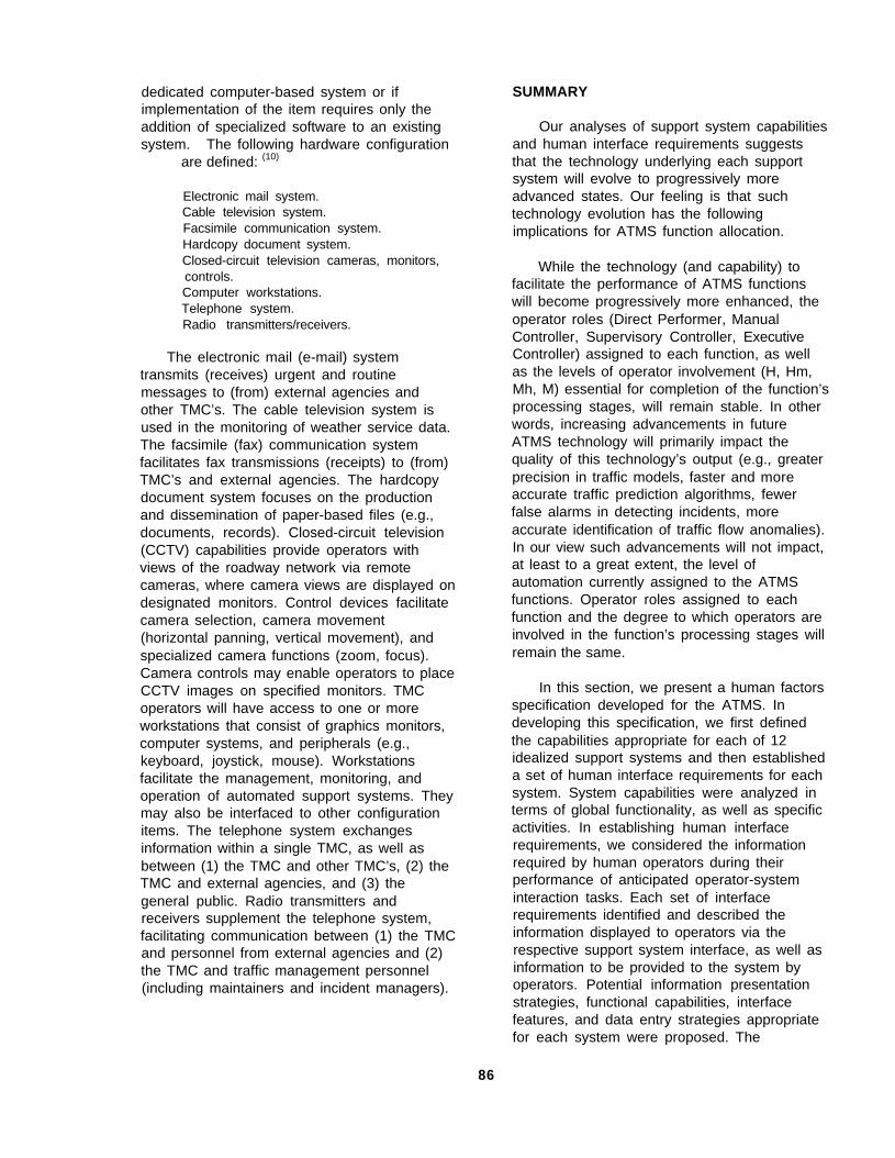
dedicated computer-based system or ifimplementation of the item requires only theaddition of specialized software to an existingsystem. The following hardware configuration
are defined: (10)
Electronic mail system.Cable television system.Facsimile communication system.Hardcopy document system.Closed-circuit television cameras, monitors,controls.Computer workstations.Telephone system.Radio transmitters/receivers.
The electronic mail (e-mail) systemtransmits (receives) urgent and routinemessages to (from) external agencies andother TMC’s. The cable television system isused in the monitoring of weather service data.The facsimile (fax) communication systemfacilitates fax transmissions (receipts) to (from)TMC’s and external agencies. The hardcopydocument system focuses on the productionand dissemination of paper-based files (e.g.,documents, records). Closed-circuit television(CCTV) capabilities provide operators withviews of the roadway network via remotecameras, where camera views are displayed ondesignated monitors. Control devices facilitatecamera selection, camera movement(horizontal panning, vertical movement), andspecialized camera functions (zoom, focus).Camera controls may enable operators to placeCCTV images on specified monitors. TMCoperators will have access to one or moreworkstations that consist of graphics monitors,computer systems, and peripherals (e.g.,keyboard, joystick, mouse). Workstationsfacilitate the management, monitoring, andoperation of automated support systems. Theymay also be interfaced to other configurationitems. The telephone system exchangesinformation within a single TMC, as well asbetween (1) the TMC and other TMC’s, (2) theTMC and external agencies, and (3) thegeneral public. Radio transmitters andreceivers supplement the telephone system,facilitating communication between (1) the TMCand personnel from external agencies and (2)the TMC and traffic management personnel(including maintainers and incident managers).
SUMMARY
Our analyses of support system capabilitiesand human interface requirements suggeststhat the technology underlying each supportsystem will evolve to progressively moreadvanced states. Our feeling is that suchtechnology evolution has the followingimplications for ATMS function allocation.
While the technology (and capability) tofacilitate the performance of ATMS functionswill become progressively more enhanced, theoperator roles (Direct Performer, ManualController, Supervisory Controller, ExecutiveController) assigned to each function, as wellas the levels of operator involvement (H, Hm,Mh, M) essential for completion of the function’sprocessing stages, will remain stable. In otherwords, increasing advancements in futureATMS technology will primarily impact thequality of this technology’s output (e.g., greaterprecision in traffic models, faster and moreaccurate traffic prediction algorithms, fewerfalse alarms in detecting incidents, moreaccurate identification of traffic flow anomalies).In our view such advancements will not impact,at least to a great extent, the level ofautomation currently assigned to the ATMSfunctions. Operator roles assigned to eachfunction and the degree to which operators areinvolved in the function’s processing stages willremain the same.
In this section, we present a human factorsspecification developed for the ATMS. Indeveloping this specification, we first definedthe capabilities appropriate for each of 12idealized support systems and then establisheda set of human interface requirements for eachsystem. System capabilities were analyzed interms of global functionality, as well as specificactivities. In establishing human interfacerequirements, we considered the informationrequired by human operators during theirperformance of anticipated operator-systeminteraction tasks. Each set of interfacerequirements identified and described theinformation displayed to operators via therespective support system interface, as well asinformation to be provided to the system byoperators. Potential information presentationstrategies, functional capabilities, interfacefeatures, and data entry strategies appropriatefor each system were proposed. The
86

capabilities and interface requirementsassociated with the set of 12 support systemsare summarized in tables 11 and 12,respectively.
Support system operation is sustained, inpart, by a set of configuration items. Suchitems are used for voice and textcommunication, information and data collection,information processing, data archiving, andcontrol of external ATMS devices. Aconfiguration item may represent a stand-alonesystem or a subsystem of a larger,multipurpose system. Eight hardwareconfiguration items were specified: electronicmail system, cable television system, facsimile
communication system, hardcopy documentsystem, CCTV system (cameras, monitors,controls), computer workstations, telephonesystem, radio transmitters/receivers.
Through our consideration of (1) supportsystem capabilities, (2) human interfacerequirements, and (3) specific hardwareconfiguration items, we have, in effect,prepared the initial framework for an ATMShuman factors specification. Note thatdevelopment of this type of specification is adynamic process. By continuing empiricalresearch efforts that focus on the humanfactors aspects of ATMS design, we willmaintain the specification. That is, throughfurther research efforts, the specification will berefined and updated.
87

Table 11. Support system capabilities.
Support System Support System Capabilities
ATCS optimize current traffic flow; control traffic signal timing andramp metering; integrate control of surface street and freewaytraffic; make low-risk predictions
PTMS
IDLS
IRAS
IDS
ITPS
TMTS
MTS
TDMS
CSS
predict traffic flow 5 to 30 min into the future; evaluatecandidate traffic management techniques (i.e., techniques thatmight be implemented in unusual conditions -- a what ifcapability); make high risk predictions
detect and verify the presence of incidents; determine the exactlocation of an incident
determine the appropriate incident response; providerecommendations for controlling traffic and disseminatinginformation; monitor incident clearance procedures anddetermine the point at which normal operations should resume;evaluate various incident response alternatives (faster thanreal-time simulation)
interface with established communications links (i.e., links toresponse forces; interface with data services; post VMSmessages; create voice messages for broadcast via HAR
support strategic planning for the ATMS; support coordinatedstrategic planning (performed in conjunction with publictransportation systems); support special event planning
provide training for TMC operators (traffic management,incident management, special event management); develop andmaintain skills required during infrequently-occurring but criticalsituations
track remedial and preventive maintenance needs andmaintenance schedules; issue maintenance requests; monitorthe status of maintenance activities (maintenance of roadwaysurfaces and electronic components); receive results ofdiagnostic tests
serve as the ATMS information hub; accept roadway sensordata; perform validity/integrity checks of data; maintain historicalrecords of traffic events and associated incidents; aggregatedata; analyze compliance measurement data; maintaincompliance information
manage the channels for two-way communications (1) within asingle TMC and (2) between TMC operators and entitiesexternal to the ATMS; support voice communications,teleconferencing, electronic mail, data base links, and faxcommunications
88

Table 11. Support system capabilities (continued).
Support System Support System Interface Requirements
ADSS support administrative activities (e.g., fiscal planning, personnelmanagement)
MTSS provide training for maintenance providers; develop and sustain skillsor procedures required for maintenance of ATMS assets
89
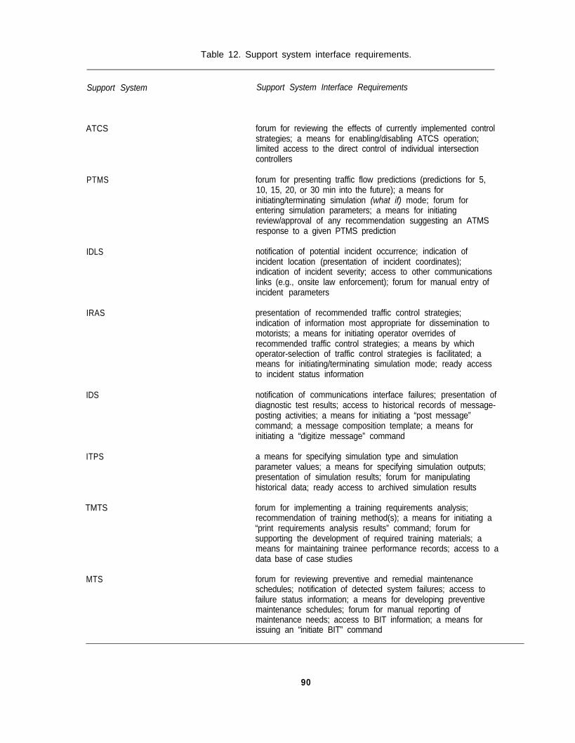
Table 12. Support system interface requirements.
Support System Support System Interface Requirements
ATCS forum for reviewing the effects of currently implemented controlstrategies; a means for enabling/disabling ATCS operation;limited access to the direct control of individual intersectioncontrollers
PTMS
IDLS
IRAS
IDS
ITPS
TMTS
MTS
forum for presenting traffic flow predictions (predictions for 5,10, 15, 20, or 30 min into the future); a means forinitiating/terminating simulation (what if) mode; forum forentering simulation parameters; a means for initiatingreview/approval of any recommendation suggesting an ATMSresponse to a given PTMS prediction
notification of potential incident occurrence; indication ofincident location (presentation of incident coordinates);indication of incident severity; access to other communicationslinks (e.g., onsite law enforcement); forum for manual entry ofincident parameters
presentation of recommended traffic control strategies;indication of information most appropriate for dissemination tomotorists; a means for initiating operator overrides ofrecommended traffic control strategies; a means by whichoperator-selection of traffic control strategies is facilitated; ameans for initiating/terminating simulation mode; ready accessto incident status information
notification of communications interface failures; presentation ofdiagnostic test results; access to historical records of message-posting activities; a means for initiating a “post message”command; a message composition template; a means forinitiating a “digitize message” command
a means for specifying simulation type and simulationparameter values; a means for specifying simulation outputs;presentation of simulation results; forum for manipulatinghistorical data; ready access to archived simulation results
forum for implementing a training requirements analysis;recommendation of training method(s); a means for initiating a“print requirements analysis results” command; forum forsupporting the development of required training materials; ameans for maintaining trainee performance records; access to adata base of case studies
forum for reviewing preventive and remedial maintenanceschedules; notification of detected system failures; access tofailure status information; a means for developing preventivemaintenance schedules; forum for manual reporting ofmaintenance needs; access to BIT information; a means forissuing an “initiate BIT” command
90
Table 12. Support system interface requirements (continued).
Support System Support System Interface Requirements
TDMS access to archived data (e.g., sensor data, weather data,anomaly data, component status data); access to datamanipulation results; access to ATMS-generated reports andreference information; access to current traffic data; notificationof deficiencies in data collection process
CSS communications interfaces (telephone/radio, teleconferencing,electronic mail, fax); forum for validating traffic data (e.g.,cellular phone calls, video cameras)
ADSS a means for coordinating the operation of applications withinthe ADSS; a means for conducting multi-tasking activities; ameans for clearly identifying functional capabilities containedwithin the ADSS
MTSS forum for implementing a training requirements analysis;recommendation of training method(s); a means for initiating a“print requirements analysis results” command; forum forsupporting the development of required training materials; ameans for maintaining trainee performance records; forum forimplementing a training requirements analysis for “refresher’courses
91

9 2

APPENDIX A.BLANK SURVEY FORM
This section contains a blank copy of the survey form from which the traffic management experts werequestioned. It begins with an introduction, where relevant background material and the purpose of theinterview were discussed with the participant. Any questions posed by the participant were thenanswered, prior to continuing with the survey questions.
93
Survey No.
HUMAN FACTORS IN ADVANCED TRAFFIC MANAGEMENT SYSTEMS EVOLUTION
Survey of Experts in Traffic Management
Performed by
Georgia Tech Research InstituteGeorgia Institute of Technology
Atlanta, GA 30332
Sponsored byFederal Highway Administration
Office of Safety and Traffic Operations R&D
Contract No. DTFH61-92-C-00094
94

Date:
Interviewers:
Thanks in advance for participating in this survey. This will be a structured interview, so I’ve got a setorder of questions for us to go through. I’ll start out by describing our research project, and tell youspecifically what we’re looking for from you today. Then I’ll ask you to tell us a little about yourself, andthen we’ll go through the questions. After that, we’ll open it up for you to elaborate on your answersand give us any general comments you might have. Finally, I’ll answer any questions you might haveat that point. Ready to start?
95

1. Introduction
Georgia Tech is under contract to the Federal Highway Administration to conduct an R&D programto examine human factors issues in future Advanced Traffic Management Systems -- that is, the trafficmanagement systems that will be needed for Intelligent Vehicle-Highway Systems to be implemented.So, our research is a part of the R&D now underway related to IVHS.
By “human factors”, I mean the jobs that humans will have to perform in Advanced TrafficManagement Systems. There are other contracts that are examining human factors issues in otheraspects of IVHS, such as automated highways, commercial vehicle operations, and of course privateautomobiles. But our piece of this big puzzle is the Advanced Traffic Management System -- or ATMS,for short. Our contract started at the end of September, so we’re just underway.
The first task in our project is to perform a functional analysis of traffic management -- not trafficmanagement as it’s done now, but how it might be done, and could be done, once the advancedtechnologies related to IVHS are implemented on the highways and in vehicles. So, we’re looking intothe future, maybe 10 to 20 years ahead. Some aspects of what we’re looking at are maybe only 5years or so away, but widespread implementation of the more advanced technologies is probably IO to20 years away.
The first step in this functional analysis is to interview experts in various aspects of trafficmanagement. We’ve got a list of about 2 dozen people, with a good mix of people from industry, localgovernments, Federal Highway, and other research organizations. There’s probably not anyone on thislist that is an expert in all the things we’re interested in, but each one of you will have an importantcontribution to make.
When we’re finished with all the interviews, we’re going to generate a functional description of a“visionary” ATMS. By “visionary”, I mean a somewhat idealized ATMS that’s not constrained by lack offunding, by political disputes, by technology that doesn’t perform as well as hoped, or by any other real-world constraint. Later on in this project, we have to revise this visionary ATMS to reflect real-worldconstraints, but at this stage we are supposed to be uncontaminated by the real world. So, forpurposes of this interview today, we want you to be very optimistic about the future of trafficmanagement.
As we go through this interview, keep a couple of things in mind. First, we are here to listen to youropinion. We understand that what you tell us will be simply that -- your opinion. Don’t feel like youneed to hold back your opinion just because it might be different from other people’s opinions, orbecause you might not be able to back it up with data, or any other reason. Second, at this stage weare not concerned with implementation issues. We aren’t concerned with what kind of systems ortechnologies would ultimately be used to accomplish the things we’re going to be talking about. So,don’t feel like you need to know how these traffic management functions that we’ll talk about wouldactually be accomplished.
Also, let me mention that your identity will be kept completely confidential. There will be absolutelyno association of your name with these forms that we’re going to write on, and there will be no way foranyone on the project or in the Government to know which opinions are yours.
The main thing we want to leave with today is an understanding of your vision of this “visionary”ATMS -- of what its goals ought to be, how it would perform, and of the top-level functions that wouldbe required to achieve those goals. To get at that vision, we’ve got a few questions that we want youropinion on. When I ask you a question, think about it as much as you’d like, and we can talk about itinformally as much as you like, and when you’re satisfied, I’ll write down your answer. Before I startasking you these questions, do you have any questions for us about our project, or what we’reexpecting from you today?
96

2. Start out by telling us about yourself, your current position here and how it’s related to trafficmanagement, and any previous positions or other experience related to traffic management. This willhelp us understand your perspective, and also will let us document in generic terms the different typesof experts that participated in these interviews.
a. Current position and relevance to traffic management:
b. Past positions and experience relevant to traffic management:
3. Next, let’s get together on terminology.
What does the term “traffic management” mean to you?
What does the term “traffic management system” mean to you?
What does the term “traffic management center” mean to you?
97

4. Keep in mind that we’re talking about an idealized ATMS, that is, a traffic management system thatwould be part of a future IVHS 10 years or more in the future. In your opinion, what are the majorproblems that an ATMS should help solve or at least improve?
5. What is the single most important objective (or goal) of an ATMS?
6. What are other very important objectives or goals of an ATMS?
98

7. Now we’re going to get more specific. I’ve got 5 scenarios. I’ll describe each scenario for you, andfor each one I’d like you to think about it, and give us your opinion on three issues: what the specificperformance goals of the ATMS should be, what major ATMS functions are important in the scenario,and your idea of what the flow of data in the system would be.
A. The first scenario is simply normal rush hour traffic. There are no weather problems, no trafficaccidents, no malfunctioning traffic lights, no abnormalities of any kind. The traffic volume on thehighway system is very near capacity.
Performance goals of the ATMS:
Important functions:
Data flow:
99

B. The second scenario is a variation on the first. Again, there is normal rush hour traffic. Thereare no weather problems, no malfunctions or abnormalities. The traffic volume on the highway systemis very near capacity. There is a minor traffic accident on a freeway. One lane of the freeway isblocked. There are no injuries, no need for an ambulance.
Performance goals of the ATMS:
Important functions:
Data flow:
100

C. The third scenario is a variation on the second. Again, there is normal rush hour traffic. Thereare no weather problems, no malfunctions or abnormalities. The traffic volume on the highway systemis very near capacity. There is a major traffic accident on a freeway. Multiple lanes of the freeway areblocked. There are serious injuries, including a life-threatening emergency.
Performance goals of the ATMS:
Important functions:
Data flow:
101

D. The fourth scenario is altogether different. This scenario involves a planned special event on theweekend -- the Super Bowl, on a Sunday evening. There are no weather problems, no malfunctions orabnormalities. The event has, of course, been scheduled well in advance, allowing ample time forplanning. Think about ATMS functions during the planning stages as well as during the event itself.
Performance goals of the ATMS:
Important functions:
Data flow:
102

E. The fifth scenario is again quite different. This scenario involves a heavy snowstorm, severeenough to have a major impact on traffic. The weather forecasters start predicting the snowstormabout 24 hours in advance, so there is some time for short-term planning. The storm hits mid-afternoon on a weekday, and continues on through the evening rush hour. In answering thesequestions, think about ATMS performance before, during, and after the storm.
Performance goals of the ATMS:
Important functions:
Data flow:
103

8. In the 5 scenarios we just went through, you thought about the major ATMS functions that wereinvolved. Now, I want you to think about other functions that will be important for an ATMS to operateeffectively. The scenarios we just went through mainly emphasized operations, and if you can think ofany more ATMS functions associated with operations, then tell us about them. But also think aboutother functions, for example, functions related to strategic planning, or maintenance, or lawenforcement, or anything else you can think of. Let’s list these functions as you think of them, andcome up with a brief description of what each function entails. It’s okay to include functions that you’vealready mentioned when we went through the scenarios.
104

9. Now concentrate on the TMC itself -- on the control room where the operators and computers thatcontrol the system are located, the command center of the ATMS.
A. In your opinion, ideally, what kind of equipment do you think would be in there?
B. What roles would human operators play? What would they be responsible for?
C. What kind of education and training would these operators have?
105

10. Complete the picture. Elaborate on anything you’ve said so far, or comment on anything else youthink we should know. Suggest other things we should look into. You talk, we’ll listen.
106
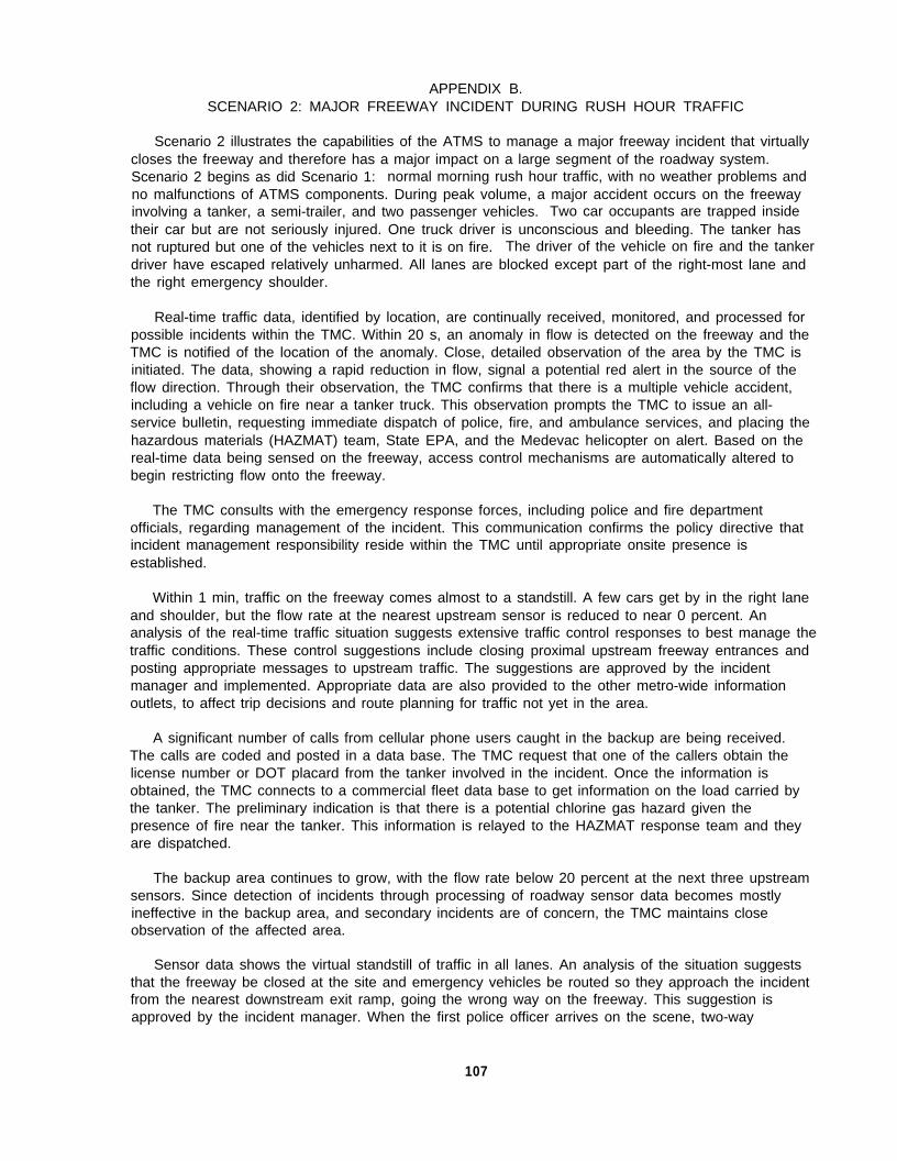
APPENDIX B.SCENARIO 2: MAJOR FREEWAY INCIDENT DURING RUSH HOUR TRAFFIC
Scenario 2 illustrates the capabilities of the ATMS to manage a major freeway incident that virtuallycloses the freeway and therefore has a major impact on a large segment of the roadway system.Scenario 2 begins as did Scenario 1: normal morning rush hour traffic, with no weather problems andno malfunctions of ATMS components. During peak volume, a major accident occurs on the freewayinvolving a tanker, a semi-trailer, and two passenger vehicles. Two car occupants are trapped insidetheir car but are not seriously injured. One truck driver is unconscious and bleeding. The tanker hasnot ruptured but one of the vehicles next to it is on fire. The driver of the vehicle on fire and the tankerdriver have escaped relatively unharmed. All lanes are blocked except part of the right-most lane andthe right emergency shoulder.
Real-time traffic data, identified by location, are continually received, monitored, and processed forpossible incidents within the TMC. Within 20 s, an anomaly in flow is detected on the freeway and theTMC is notified of the location of the anomaly. Close, detailed observation of the area by the TMC isinitiated. The data, showing a rapid reduction in flow, signal a potential red alert in the source of theflow direction. Through their observation, the TMC confirms that there is a multiple vehicle accident,including a vehicle on fire near a tanker truck. This observation prompts the TMC to issue an all-service bulletin, requesting immediate dispatch of police, fire, and ambulance services, and placing thehazardous materials (HAZMAT) team, State EPA, and the Medevac helicopter on alert. Based on thereal-time data being sensed on the freeway, access control mechanisms are automatically altered tobegin restricting flow onto the freeway.
The TMC consults with the emergency response forces, including police and fire departmentofficials, regarding management of the incident. This communication confirms the policy directive thatincident management responsibility reside within the TMC until appropriate onsite presence isestablished.
Within 1 min, traffic on the freeway comes almost to a standstill. A few cars get by in the right laneand shoulder, but the flow rate at the nearest upstream sensor is reduced to near 0 percent. Ananalysis of the real-time traffic situation suggests extensive traffic control responses to best manage thetraffic conditions. These control suggestions include closing proximal upstream freeway entrances andposting appropriate messages to upstream traffic. The suggestions are approved by the incidentmanager and implemented. Appropriate data are also provided to the other metro-wide informationoutlets, to affect trip decisions and route planning for traffic not yet in the area.
A significant number of calls from cellular phone users caught in the backup are being received.The calls are coded and posted in a data base. The TMC request that one of the callers obtain thelicense number or DOT placard from the tanker involved in the incident. Once the information isobtained, the TMC connects to a commercial fleet data base to get information on the load carried bythe tanker. The preliminary indication is that there is a potential chlorine gas hazard given thepresence of fire near the tanker. This information is relayed to the HAZMAT response team and theyare dispatched.
The backup area continues to grow, with the flow rate below 20 percent at the next three upstreamsensors. Since detection of incidents through processing of roadway sensor data becomes mostlyineffective in the backup area, and secondary incidents are of concern, the TMC maintains closeobservation of the affected area.
Sensor data shows the virtual standstill of traffic in all lanes. An analysis of the situation suggeststhat the freeway be closed at the site and emergency vehicles be routed so they approach the incidentfrom the nearest downstream exit ramp, going the wrong way on the freeway. This suggestion isapproved by the incident manager. When the first police officer arrives on the scene, two-way
107
communication between the TMC and the officer is established. The officer is advised of the potentialHAZMAT situation and instructed to close the right lane and shoulder until further notice. TMC reflectsthis information in updated messages provided to the upstream traffic.
Through observation, the TMC confirms that the downstream freeway segment is free of traffic, andthe routing of emergency vehicles to approach from that direction is implemented. Traffic controls areoverridden by the TMC to create priority control on the surface streets in order to get them to theappropriate ramp.
Traffic on the freeway is now backed up for 9.66 km (6 mi). The real-time traffic data received bythe TMC are used to make predictions about the state of traffic 5, 10, and 20 min into the future.These predictions are dire, and an analysis of various responses is performed to determine theresponse leading to the best predicted outcome. The recommended solution includes completelyshutting down several upstream entrance ramps, adjusting the flow control of off-ramps toaccommodate the very heavy flow off the freeway, and updating all appropriate information outlets.The incident manager accepts this solution and it is implemented. Traffic controls on affected surfacestreets automatically respond to the increased traffic flow.
Because of the possible HAZMAT condition, the TMC initiates an analysis to determine the bestevacuation plan. This analysis uses real-time traffic data to develop a detailed contingency plan for thissituation.
The incident manager orders the entire freeway from the nearest upstream interchange with anotherfreeway down to the incident site to be closed. TMC performs a quick analysis to determine the bestalternate routes for the displaced vehicles. The order is implemented via TMC override of automatedtraffic controls, closing all affected entrance ramps. Traffic advisories reflecting the closing andalternate routes are posted on all area and metro-wide information outlets. Based on the real-timesensing of increased flow, traffic controls along the alternate routes automatically adapt.
Response forces arrive at the scene, including fire, ambulance, the HAZMAT team, and additionalpolice. Incident management responsibility is passed to the appropriate onsite personnel according tostandard procedures. The TMC confirms that all upstream traffic in the backup has been diverted offthe freeway, except for the vehicles trapped between the nearest upstream exit and the incident site.Police are informed of the situation and the need to begin removing those vehicles, in case theHAZMAT situation is serious. The police begin manually directing those cars to turn around andproceed to the last entrance in order to exit the freeway.
The TMC continues to monitor the backup for secondary incidents, but concentrates on managingthe abnormal traffic patterns created by the closed freeway. Algorithms used to adjust traffic controls inattempt to maintain optimal flow are adapted to the situation, reflecting the closed freeway. The TMCmaintains communication with onsite personnel, and as information is obtained from the incident site, itis filtered and passed on to appropriate information outlets.
Once the vehicle fire is extinguished and the HAZMAT team clears the tanker, the HAZMATcondition is canceled. The incident manager opens the right lane and shoulder to allow remainingvehicles trapped in the backup to pass. The TMC is made aware of these changes and update themessages provided to those vehicles stuck in the area. The TMC is also made aware of road surfacedamage caused by the vehicle fire. The TMC places a priority work order with the appropriate roadmaintenance agency, who is immediately dispatched.
When all injured individuals have been transported from the scene, tow trucks begin removing thewreckage. The road crew arrives on the scene and sets up barricades. Once all vehicles and debrisare removed from the roadway, the onsite incident manager returns control to the TMC. It is orderedthat the freeway be reopened, but that all information outlets, area and metro-wide, be updated toinclude information as to the damaged roadway and the maintenance activity underway.
108

When the repairs are completed, the posted advisories are deleted and the roadway system returnsto normal in time for the evening rush hour. The following day, an event debriefing is held withrepresentatives of all involved agencies.
109

110
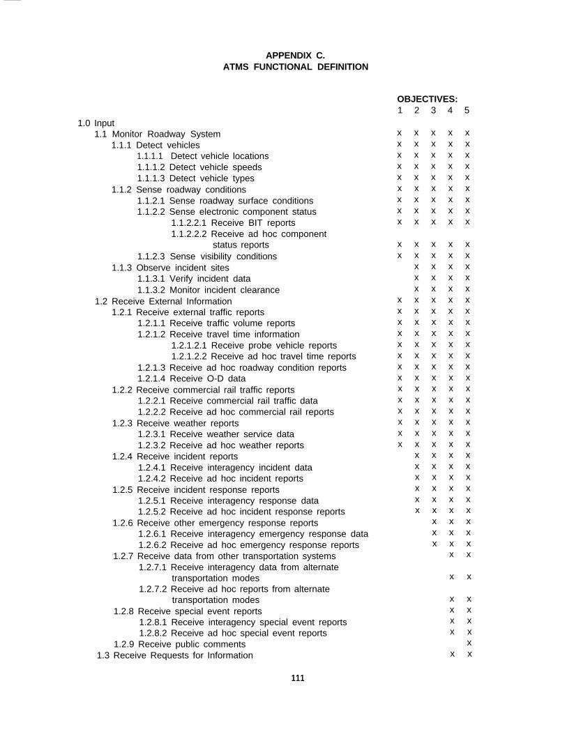
APPENDIX C.ATMS FUNCTIONAL DEFINITION
OBJECTIVES:1 2 3 4 5
1.0 Input1.1 Monitor Roadway System
1.1.1 Detect vehicles1.1.1.1 Detect vehicle locations1.1.1.2 Detect vehicle speeds1.1.1.3 Detect vehicle types
1.1.2 Sense roadway conditions1.1.2.1 Sense roadway surface conditions1.1.2.2 Sense electronic component status
1.1.2.2.1 Receive BIT reports1.1.2.2.2 Receive ad hoc component
status reports1.1.2.3 Sense visibility conditions
1.1.3 Observe incident sites1.1.3.1 Verify incident data1.1.3.2 Monitor incident clearance
1.2 Receive External Information1.2.1 Receive external traffic reports
1.2.1.1 Receive traffic volume reports1.2.1.2 Receive travel time information
1.2.1.2.1 Receive probe vehicle reports1.2.1.2.2 Receive ad hoc travel time reports
1.2.1.3 Receive ad hoc roadway condition reports1.2.1.4 Receive O-D data
1.2.2 Receive commercial rail traffic reports1.2.2.1 Receive commercial rail traffic data1.2.2.2 Receive ad hoc commercial rail reports
1.2.3 Receive weather reports1.2.3.1 Receive weather service data1.2.3.2 Receive ad hoc weather reports
1.2.4 Receive incident reports1.2.4.1 Receive interagency incident data1.2.4.2 Receive ad hoc incident reports
1.2.5 Receive incident response reports1.2.5.1 Receive interagency response data1.2.5.2 Receive ad hoc incident response reports
1.2.6 Receive other emergency response reports1.2.6.1 Receive interagency emergency response data1.2.6.2 Receive ad hoc emergency response reports
1.2.7 Receive data from other transportation systems1.2.7.1 Receive interagency data from alternate
transportation modes1.2.7.2 Receive ad hoc reports from alternate
transportation modes1.2.8 Receive special event reports
1.2.8.1 Receive interagency special event reports1.2.8.2 Receive ad hoc special event reports
1.2.9 Receive public comments1.3 Receive Requests for Information
x x x x xx x x x xx x x x xx x x x xx x x x xx x x x xx x x x xx x x x xx x x x x
x x x x xx x x x x
x x x xx x x xx x x x
x x x x xx x x x xx x x x xx x x x xx x x x xx x x x xx x x x xx x x x xx x x x xx x x x xx x x x xx x x x xx x x x xx x x x x
x x x xx x x xx x x xx x x xx x x xx x x x
x x xx x xx x x
x x
x x
x xx xx xx x
xx x
111

1.3.1 Receive requests for historical data1.3.2 Receive requests for simulation studies1.3.3 Receive requests for public relations activities
x xx x
X
2.0 Throughput 2.1 Select Traffic Management Tactics
2.1.1 Assess network conditions2.1.1.1 Assess current load2.1.1.2 Anticipate near-term traffic conditions
2.1.2 Determine optimal control scheme2.1.2.1 Identify traffic control options2.1.2.2 Predict traffic conditions given options2.1.2.3 Assess predicted traffic conditions given options2.1.2.4 Select best traffic control option
2.1.3 Determine special vehicle support measures2.1.3.1 Determine need for ATMS support2.1.3.2 Track special vehicles
2.2 Determine System Welfare Needs2.2.1 Assess traffic management system effectiveness2.2.2 Determine maintenance needs
2.2.2.1 Determine remedial maintenance needs2.2.2.2 Determine preventative maintenance needs
2.2.3 Determine upgrade needs2.2.3.1 Determine software upgrade needs2.2.3.2 Determine hardware upgrade needs2.2.3.3 Determine personnel upgrade needs
2.3 Assess Anomalies2.3.1 Identify anomalies in traffic patterns2.3.2 Determine source of anomalies
2.4 Select ATMS Responses to Incidents2.4.1 Determine ATMS responsibilities2.4.2 Determine need for incident services2.4.3 Determine appropriate ATMS responses
2.5 Conduct Simulations to Support Transportation Planning2.5.1 Assess multimodal demand and capacity2.5.2 Determine optimal demand regulation scheme
2.5.2.1 Identify demand regulation options2.5.2.2 Predict multimodal demand given options2.5.2.3 Assess predicted multimodal demand2.5.2.4 Formulate demand regulation recommendation
2.6 Assess Public Confidence2.6.1 Monitor compliance with advisories
2.6.1.1 Monitor compliance with current advisories2.6.1.2 Monitor general compliance with advisories
2.6.2 Assess public comments2.6.2.1 Assess survey data2.6.2.2 Assess ad hoc public comments
2.6.3 Plan public confidence enhancements
3.0 output3.1 Influence Traffic
3.1.1 Implement traffic controls3.1.1.1 Control access to roadway segments3.1.1.2 Control intersections3.1.1.3 Control railroad crossings
x x x x xx x x x xx x x x xx x x x xx x x x xx x x x xx x x x xx x x x xx x x x x
x x xx x xx x x
x x x x xx x x x xx x x x xx x x x xx x x x xx x x x xx x x x xx x x x xx x x x x
x x x xx x x xx x x xx x x xx x x xx x x xx x x x
x xx xx xx xx xx xx x
XX
x x x x xx x x x xx x x x xx x x x xx x x x x
112

3.1.2 Issue advisories3.1.2.1 Issue route selection advisories
3.1.2.1.1 Post route selection advisories oninformation outlets
3.1.2.1.2 Post route selection advisories toother users
3.1.2.2 Issue speed limit advisories3.1.2.2.1 Post speed advisories on
information outlets3.1.2.2.2 Provide speed advisories
to other users3.1.2.3 Issue travel advisories
3.1.2.3.1 Post travel advisories on informationoutlets
3.1.2.3.2 Provide travel advisories to other users3.1.2.4 Issue mode selection advisories
3.1.2.4.1 Post mode advisories oninformation outlets
3.1.2.4.2 Provide mode advisories toother users
3.2 Issue Requests3.2.1 Issue maintenance requests
3.2.1.1 Transmit electronic maintenance requests3.2.1.2 Issue special maintenance requests
3.2.2 Issue upgrade requests3.2.3 Issue incident service requests
3.2.3.1 Transmit electronic incident service requests3.2.3.2 Issue special incident service requests
3.2.4 Issue requests for information3.2.5 Issue requests for onsite traffic control
3.3 Provide Information3.3.1 Provide incident reports
3.3.1.1 Transmit electronic incident reports3.3.1.2 Issue special incident reports
3.3.2 Provide incident management reports3.3.2.1 Transmit electronic incident management reports3.3.2.2 Issue special incident management reports
3.3.3 Provide historical traffic data3.3.4 Provide simulation reports and recommendations3.3.5 Provide public relations information
4.0 support4.1 Maintain Records
4.1.1 Store network data4.1.2 Retrieve network data4.1.3 Store incident data
4.1.3.1 Store electronic incident data4.1.3.2 Store hard copy of incident reports
4.1.4 Retrieve incident data4.1.4.1 Retrieve electronic incident data4.1.4.2 Retrieve hard copy of incident reports
4.1.5 Perform Data base Management4.2 Provide Training
4.2.1 Provide traffic management training4.2.2 Provide maintainer training
x x x x xx x x x x
x x x x x
x x x x xx x x x x
x x x x x
x x x x xx x
x xx xx x
x x
x xx x x x xx x x x xx x x x xx x x x xx x x x x
x x x xx x x xx x x xx x x x
x x x x xx x x xx x x xx x x xx x x xx x x xx x x xx x x x
x xx x
X
x x x x xx x x x xx x x x x
x x x xx x x xx x x xx x x xx x x xx x x x
x x x x xx x x x xx x x x xx x x x x
113

4.2.3 Provide incident management training4.2.4 Provide special events training
4.3 Develop Traffic Management Plans4.3.1 Develop strategic traffic management plans4.3.2 Develop special event traffic management plans4.3.3 Develop traffic management contingency plans
4.4 Perform Administrative Duties4.4.1 Formulate Policy and Procedures
4.4.1.1 Receive directives4.4.1.2 Develop policy4.4.1.3 Specify procedures4.4.1.4 Implement policy and procedures
4.4.2 Manage Financial Resources4.4.2.1 Perform fiscal planning4.4.2.2 Perform budget tracking
4.4.3 Manage Personnel4.4.3.1 Perform evaluations4.4.3.2 Perform personnel selection4.4.3.3 Maintain personnel records
4.5 Provide Interagency Coordination4.5.1 Maintain communications with incident responders4.5.2 Coordinate multi-agency incident response4.5.3 Coordinate multi-agency response to
other emergencies4.5.4 Coordinate multi-agency transportation planning
x x x xx x
x x x x xx x x x xx x x x xx x x x xx x x x xx x x x xx x x x xx x x x xx x x x xx x x x xx x x x xx x x x xx x x x xx x x x xx x x x xx x x x xx x x x x
x x x xx x x xx x x x
x x xx x
114
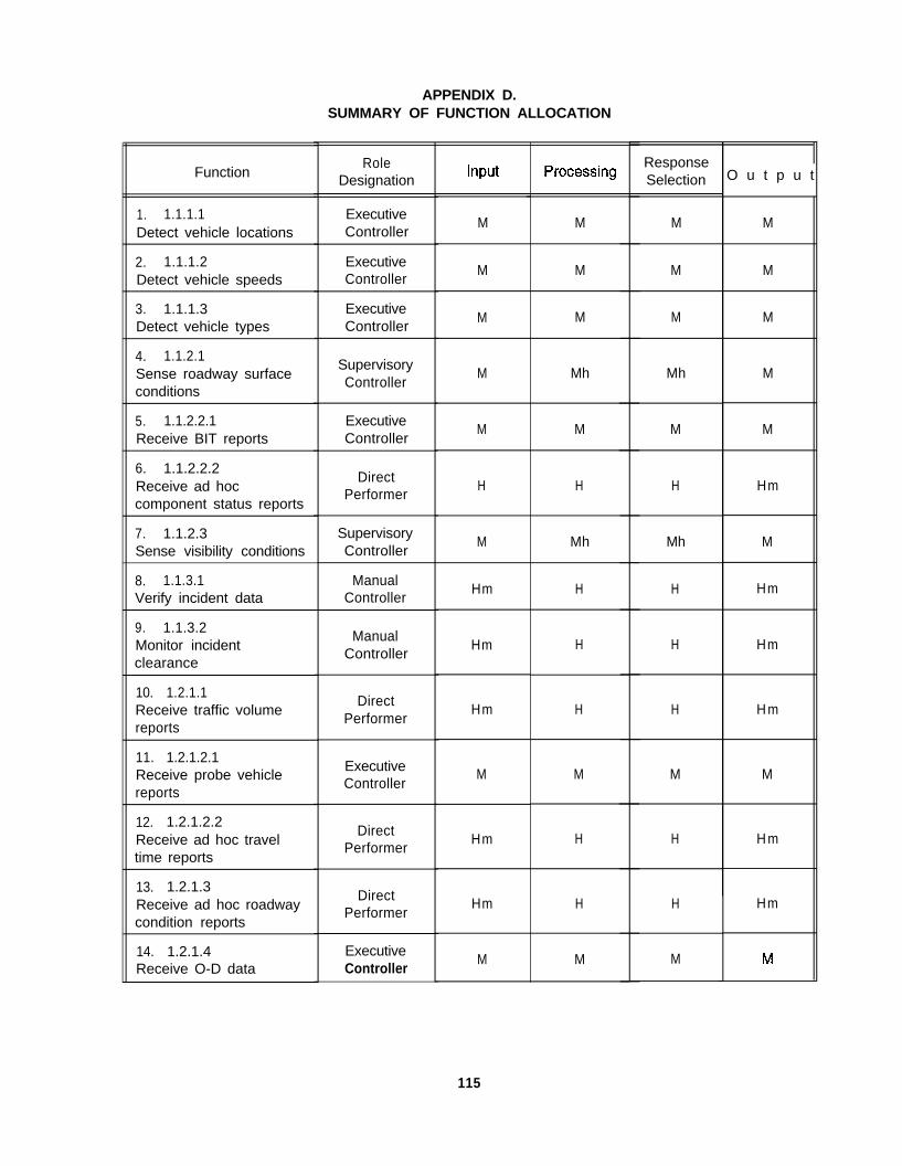
APPENDIX D.SUMMARY OF FUNCTION ALLOCATION
Function
1. 1.1.1.1Detect vehicle locations
2. 1.1.1.2Detect vehicle speeds
3. 1.1.1.3Detect vehicle types
4. 1.1.2.1Sense roadway surfaceconditions
5. 1.1.2.2.1Receive BIT reports
6. 1.1.2.2.2Receive ad hoccomponent status reports
7. 1.1.2.3Sense visibility conditions
8. 1.1.3.1Verify incident data
9. 1.1.3.2Monitor incidentclearance
10. 1.2.1.1Receive traffic volumereports
11. 1.2.1.2.1Receive probe vehiclereports
12. 1.2.1.2.2Receive ad hoc traveltime reports
13. 1.2.1.3Receive ad hoc roadwaycondition reports
14. 1.2.1.4Receive O-D data
RoleDesignation
ExecutiveController
ExecutiveController
ExecutiveController
SupervisoryController
ExecutiveController
DirectPerformer
SupervisoryController
ManualController
ManualController
DirectPerformer
ExecutiveController
DirectPerformer
DirectPerformer
ExecutiveController
M
M
M
M
M
H
M
Hm
Hm
Hm
M
Hm
Hm
M
M
M
M
Mh
M
H
Mh
H
H
H
M
H
H
M
ResponseSelection
M
M
M
Mh
M
H
Mh
H
H
H
M
H
H
M
O u t p u t
M
M
M
M
M
Hm
M
Hm
Hm
H m
M
H m
Hm
115

116

Function
27. 1.2.8.1Receive interagencyspecial event reports
RoleDesignation
ExecutiveController
Input
M
ProcessingResponseSelection
output
M M M
28. 1.2.8.2Receive ad hoc specialevent reports
29. 1.2.9Receive public comments
30. 1.3.1Receive requests forhistorical data
DirectPerformer
DirectPerformer
DirectPerformer
Hm H H H m
Hm H H Hm
H m H H H m
31. 1.3.2Receive requests forsimulation studies
DirectPerformer
Hm H H H m
32. 1.3.3Receive requests forpublic relations activities
DirectPerformer
Hm H H Hm
33. 2.1.1.1Assess current load
34. 2.1.1.2Anticipate near-termtraffic conditions
SupervisoryController
Supervisorycontroller
M
M
Mh
Mh
Mh
Mh
M
M
35. 2.1.2.1Identify traffic controloptions
SupervisoryController
M Mh Mh M
36. 2.1.2.2Predict traffic conditionsgiven options
37. 2.1.2.3Assess predicted trafficconditions given options
SupervisoryController
SupervisoryController
M
M
Mh
Mh
Mh
Mh
M
M
38. 2.1.2.4Select best traffic controloption
Supervisory MController
Mh Mh M
39. 2.1.3.1Determine need forATMS support (forspecial vehicles)
SupervisoryController
M Mh Mh
40. 2.1.3.2 ExecutiveTrack special vehicles Controller
M M M M
117
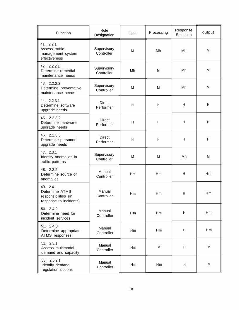
Function
41. 2.2.1Assess trafficmanagement systemeffectiveness
42. 2.2.2.1Determine remedialmaintenance needs
43. 2.2.2.2Determine preventativemaintenance needs
44. 2.2.3.1Determine softwareupgrade needs
45. 2.2.3.2Determine hardwareupgrade needs
46. 2.2.3.3Determine personnelupgrade needs
47. 2.3.1Identify anomalies intraffic patterns
48. 2.3.2Determine source ofanomalies
49. 2.4.1Determine ATMSresponsibilities (inresponse to incidents)
50. 2.4.2Determine need forincident services
51. 2.4.3Determine appropriateATMS responses
52. 2.5.1Assess multimodaldemand and capacity
53. 2.5.2.1Identify demandregulation options
RoleDesignation
SupervisoryController
SupervisoryController
SupervisoryController
DirectPerformer
DirectPerformer
DirectPerformer
SupervisoryController
ManualController
ManualController
ManualController
ManualController
ManualController
ManualController
Input
M
Mh
M
H
H
H
M
Hm
Hm
Hm
Hm
Hm
Hm
Processing
Mh
M
M
H
H
H
M
Hm
Hm
Hm
Hm
M
Hm
ResponseSelection
Mh
Mh
Mh
H
H
H
Mh
H
H
H
H
H
H
output
M
M
M
H
H
H
M
Hm
Hm
Hm
Hm
M
M
118

Function
54. 2.5.2.2Predict multimodaldemand given options
55. 2.5.2.3Assess predictedmultimodal demand
RoleDesignation
SupervisoryController
SupervisoryController
Input ProcessingResponseSelection
output
Mh M Mh M
M M Mh M
56. 2.5.2.4Formulate demandregulationrecommendation
DirectPerformer
Hm H H H m
57. 2.6.1.1Monitor compliance withcurrent advisories
SupervisoryController
M M Mh M
58. 2.6.1.2Monitor generalcompliance withadvisories
ManualController
Hm M H M
59. 2.6.2.1Assess survey data
60. 2.6.2.2Assess ad hoc publiccomments
ManualController
DirectPerformer
Hm M H M
Hm H H H
61. 2.6.3Plan public confidenceenhancements
DirectPerformer
Hm H H H
62. 3.1.1.1Control access toroadway segments
63. 3.1.1.2Control intersections
64. 3.1.1.3Control railroad crossings
65. 3.1.2.1.1Post route advisories on
information outlets
66. 3.1.2.1.2Provide route advisoriesto other users
ExecutiveController
ExecutiveController
ExecutiveController
ExecutiveController
DirectPerformer
M M M M
M M M M
MM M M
M M M M
Hm H H H m
67. 3.1.2.2.1Post speed advisories on
Executive
information outletsController
M M M M
119
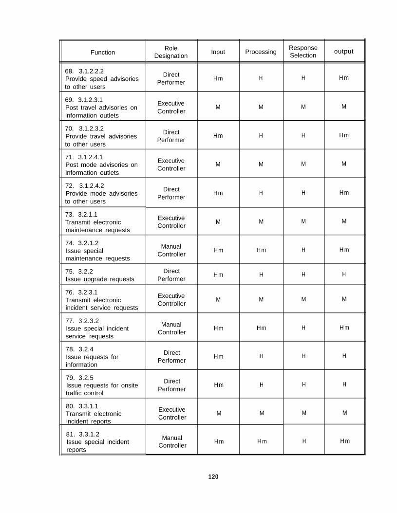
FunctionRole
DesignationInput
ResponseProcessing Selection
output
68. 3.1.2.2.2Provide speed advisoriesto other users
DirectPerformer
Hm H H H m
69. 3.1.2.3.1Post travel advisories oninformation outlets
ExecutiveController
M M M M
70. 3.1.2.3.2Provide travel advisoriesto other users
DirectPerformer
Hm H H Hm
71. 3.1.2.4.1Post mode advisories oninformation outlets
ExecutiveController
M M M M
72. 3.1.2.4.2Provide mode advisories
DirectPerformer
Hm H H Hmto other users
73. 3.2.1.1Transmit electronic
ExecutiveController
M M M Mmaintenance requests
74. 3.2.1.2Issue specialmaintenance requests
ManualController
Hm Hm H H m
75. 3.2.2 DirectIssue upgrade requests Performer
Hm H H H
76. 3.2.3.1Transmit electronicincident service requests
ExecutiveController
M M M M
77. 3.2.3.2Issue special incidentservice requests
ManualController
Hm Hm H H m
78. 3.2.4Issue requests forinformation
79. 3.2.5Issue requests for onsitetraffic control
80. 3.3.1.1Transmit electronicincident reports
81. 3.3.1.2Issue special incidentreports
DirectPerformer
DirectPerformer
ExecutiveController
ManualController
Hm H H H
Hm H H H
M M M M
Hm Hm H H m
120

Function
82. 3.3.2.1Transmit electronicincident managementreports
RoleDesignation
ExecutiveController
Input
M
Processing
M
ResponseSelection
M
output
M
83. 3.3.2.2Issue special incidentmanagement reports
ManualController
Hm Hm H Hm
84. 3.3.3Provide historical trafficdata
ManualController
Hm Hm H Hm
85. 3.3.4Provide simulationreports andrecommendations
ManualController
Hm Hm H Hm
86. 3.3.5Provide public relationsinformation
ManualController
Hm Hm H Hm
87. 4.1.1Store network data
88. 4.1.2Retrieve network data
89. 4.1.3.1Store electronic incidentdata
ExecutiveController
ExecutiveController
ExecutiveController
M M M M
M M M M
M M M M
90. 4.1.3.2Store hardcopy ofincident reports
DirectPerformer
H H H H
91. 4.1.4.1Retrieve electronicincident data
ExecutiveController
M M M M
92. 4.1.4.2Retrieve hardcopy ofincident reports
DirectPerformer
H H H H
93. 4.1.5Perform data basemanagement
ManualController
Hm Hm H Hm
94. 4.2.1Provide trafficmanagement training
ManualController
H Hm H Hm
121

FunctionRole
DesignationInput
ResponseProcessing Selection
output
95. 4.2.2Provide maintainertraining
ManualController
H Hm H Hm
96. 4.2.3Provide incidentmanagement training
ManualController
H Hm H Hm
97. 4.2.4Provide special eventstraining
ManualController
H Hm H Hm
98. 4.3.1Develop strategic trafficmanagement plans
ManualController
H Hm H H m
99. 4.3.2Develop special eventtraffic management plans
ManualController
Hm Hm H Hm
100. 4.3.3Develop trafficmanagement contingencyplans
ManualController
Hm Hm H Hm
101. 4.4.1.1 DirectReceive directives Performer
H H H H
102. 4.4.1.2Develop policy
DirectPerformer
H H H H
103. 4.4.1.3Specify procedures
DirectPerformer
H H H H
104. 4.4.1.4Implement policy andprocedures
DirectPerformer
H H H Hm
105. 4.4.2.1Perform fiscal planning
H Hm H Hm
106. 4.4.2.2Perform budget tracking
ManualController
ManualController
H HmH Hm
107. 4.4.3.1Perform evaluations
108. 4.4.3.2Perform personnelselection
DirectPerformer
DirectPerformer
H H H H
HH H H
109. 4.4.3.3Maintain personnelrecords
ManualController
H Hm H M
122

FunctionRole
DesignationInput Processing
ResponseSelection
output
110. 4.5.1Maintain communicationswith incident responders
DirectPerformer
Hm H H H
111. 4.5.2Coordinate multi-agencyincident response
DirectPerformer
H H H H
112. 4.5.3Coordinate multi-agencyresponse to otheremergencies
DirectPerformer
H H H H
113. 4.5.4Coordinate multi-agency
Direct H Htransportation planning
PerformerH H
123

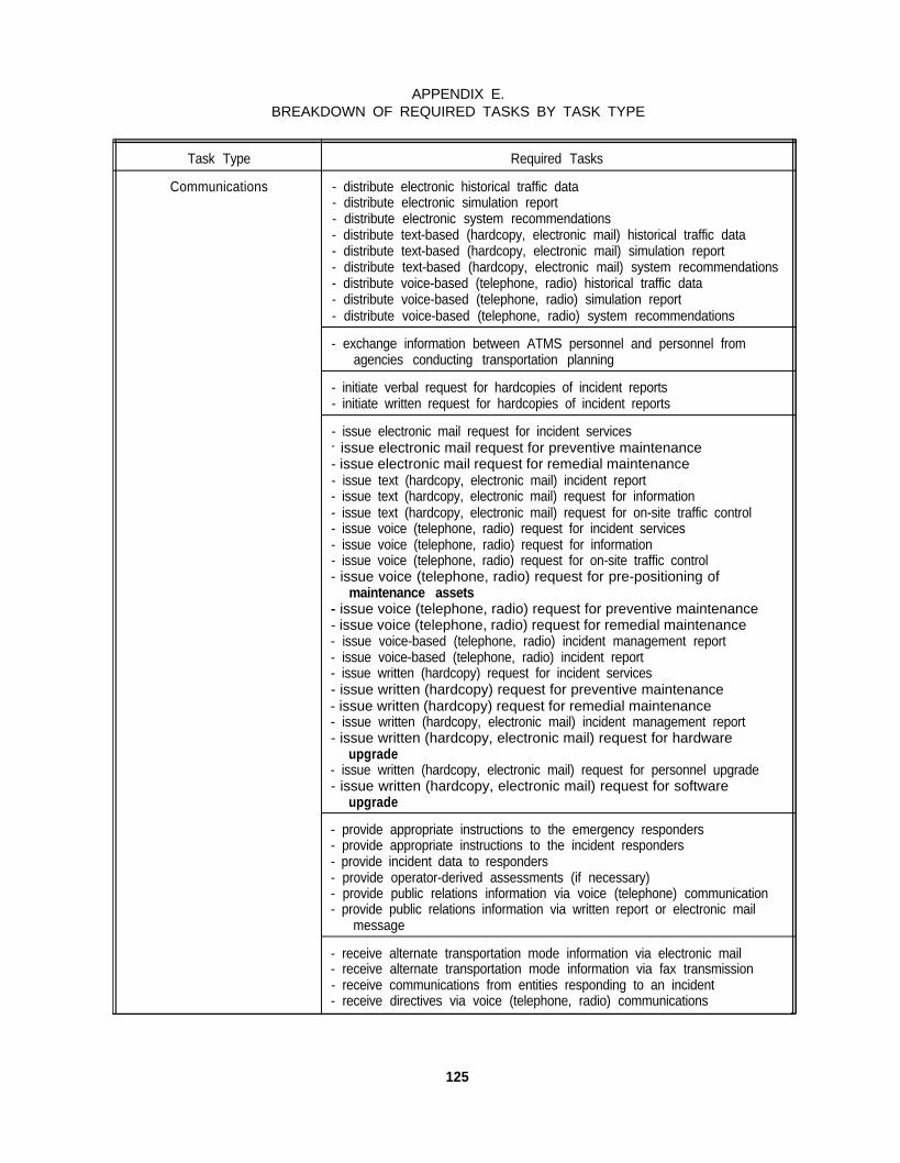
APPENDIX E.BREAKDOWN OF REQUIRED TASKS BY TASK TYPE
Task Type
Communications
Required Tasks
- distribute electronic historical traffic data- distribute electronic simulation report- distribute electronic system recommendations- distribute text-based (hardcopy, electronic mail) historical traffic data- distribute text-based (hardcopy, electronic mail) simulation report- distribute text-based (hardcopy, electronic mail) system recommendations- distribute voice-based (telephone, radio) historical traffic data- distribute voice-based (telephone, radio) simulation report- distribute voice-based (telephone, radio) system recommendations
- exchange information between ATMS personnel and personnel fromagencies conducting transportation planning
- initiate verbal request for hardcopies of incident reports- initiate written request for hardcopies of incident reports
- issue electronic mail request for incident services- issue electronic mail request for preventive maintenance- issue electronic mail request for remedial maintenance- issue text (hardcopy, electronic mail) incident report- issue text (hardcopy, electronic mail) request for information- issue text (hardcopy, electronic mail) request for on-site traffic control- issue voice (telephone, radio) request for incident services- issue voice (telephone, radio) request for information- issue voice (telephone, radio) request for on-site traffic control- issue voice (telephone, radio) request for pre-positioning of
maintenance assets- issue voice (telephone, radio) request for preventive maintenance- issue voice (telephone, radio) request for remedial maintenance- issue voice-based (telephone, radio) incident management report- issue voice-based (telephone, radio) incident report- issue written (hardcopy) request for incident services- issue written (hardcopy) request for preventive maintenance- issue written (hardcopy) request for remedial maintenance- issue written (hardcopy, electronic mail) incident management report- issue written (hardcopy, electronic mail) request for hardware
upgrade- issue written (hardcopy, electronic mail) request for personnel upgrade- issue written (hardcopy, electronic mail) request for software
upgrade
- provide appropriate instructions to the emergency responders- provide appropriate instructions to the incident responders- provide incident data to responders- provide operator-derived assessments (if necessary)- provide public relations information via voice (telephone) communication- provide public relations information via written report or electronic mail
message
- receive alternate transportation mode information via electronic mail- receive alternate transportation mode information via fax transmission- receive communications from entities responding to an incident- receive directives via voice (telephone, radio) communications
125
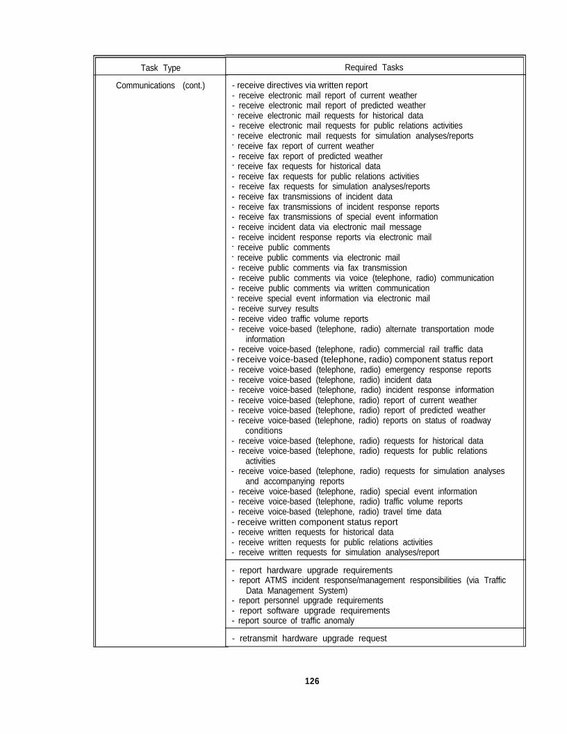
Task Type
Communications (cont.)
Required Tasks
- receive directives via written report- receive electronic mail report of current weather- receive electronic mail report of predicted weather- receive electronic mail requests for historical data- receive electronic mail requests for public relations activities- receive electronic mail requests for simulation analyses/reports- receive fax report of current weather- receive fax report of predicted weather- receive fax requests for historical data- receive fax requests for public relations activities- receive fax requests for simulation analyses/reports- receive fax transmissions of incident data- receive fax transmissions of incident response reports- receive fax transmissions of special event information- receive incident data via electronic mail message- receive incident response reports via electronic mail- receive public comments- receive public comments via electronic mail- receive public comments via fax transmission- receive public comments via voice (telephone, radio) communication- receive public comments via written communication- receive special event information via electronic mail- receive survey results- receive video traffic volume reports- receive voice-based (telephone, radio) alternate transportation mode
information- receive voice-based (telephone, radio) commercial rail traffic data- receive voice-based (telephone, radio) component status report- receive voice-based (telephone, radio) emergency response reports- receive voice-based (telephone, radio) incident data- receive voice-based (telephone, radio) incident response information- receive voice-based (telephone, radio) report of current weather- receive voice-based (telephone, radio) report of predicted weather- receive voice-based (telephone, radio) reports on status of roadway
conditions- receive voice-based (telephone, radio) requests for historical data- receive voice-based (telephone, radio) requests for public relations
activities- receive voice-based (telephone, radio) requests for simulation analyses
and accompanying reports- receive voice-based (telephone, radio) special event information- receive voice-based (telephone, radio) traffic volume reports- receive voice-based (telephone, radio) travel time data- receive written component status report- receive written requests for historical data- receive written requests for public relations activities- receive written requests for simulation analyses/report
- report hardware upgrade requirements- report ATMS incident response/management responsibilities (via Traffic
Data Management System)- report personnel upgrade requirements- report software upgrade requirements- report source of traffic anomaly
- retransmit hardware upgrade request
126
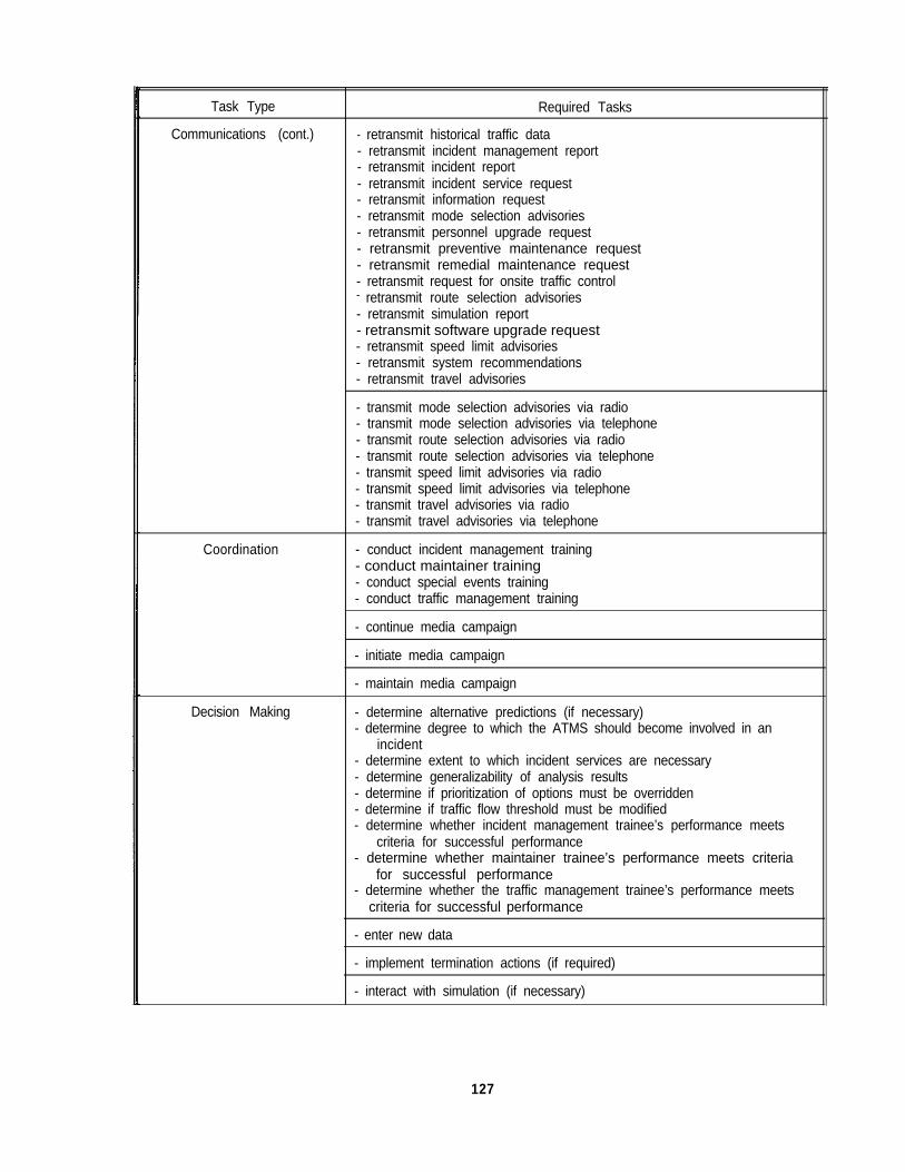
Task Type
Communications (cont.)
Required Tasks
- retransmit historical traffic data- retransmit incident management report- retransmit incident report- retransmit incident service request- retransmit information request- retransmit mode selection advisories- retransmit personnel upgrade request- retransmit preventive maintenance request- retransmit remedial maintenance request- retransmit request for onsite traffic control- retransmit route selection advisories- retransmit simulation report- retransmit software upgrade request- retransmit speed limit advisories- retransmit system recommendations- retransmit travel advisories
- transmit mode selection advisories via radio- transmit mode selection advisories via telephone- transmit route selection advisories via radio- transmit route selection advisories via telephone- transmit speed limit advisories via radio- transmit speed limit advisories via telephone- transmit travel advisories via radio- transmit travel advisories via telephone
Coordination - conduct incident management training- conduct maintainer training- conduct special events training- conduct traffic management training
- continue media campaign
- initiate media campaign
- maintain media campaign
Decision Making - determine alternative predictions (if necessary)- determine degree to which the ATMS should become involved in an
incident- determine extent to which incident services are necessary- determine generalizability of analysis results- determine if prioritization of options must be overridden- determine if traffic flow threshold must be modified- determine whether incident management trainee’s performance meets
criteria for successful performance- determine whether maintainer trainee’s performance meets criteria
for successful performance- determine whether the traffic management trainee’s performance meets
criteria for successful performance
- enter new data
- implement termination actions (if required)
- interact with simulation (if necessary)
127
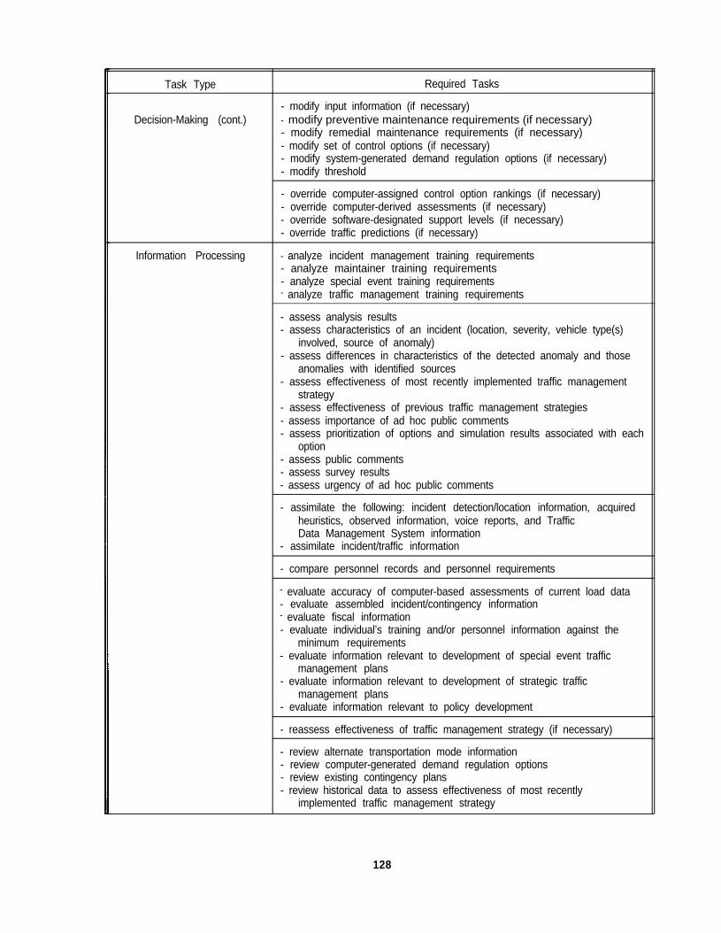
Task Type
Decision-Making (cont.)
Required Tasks
- modify input information (if necessary)- modify preventive maintenance requirements (if necessary)- modify remedial maintenance requirements (if necessary)- modify set of control options (if necessary)- modify system-generated demand regulation options (if necessary)- modify threshold
- override computer-assigned control option rankings (if necessary)- override computer-derived assessments (if necessary)- override software-designated support levels (if necessary)- override traffic predictions (if necessary)
Information Processing - analyze incident management training requirements- analyze maintainer training requirements- analyze special event training requirements- analyze traffic management training requirements
- assess analysis results- assess characteristics of an incident (location, severity, vehicle type(s)
involved, source of anomaly)- assess differences in characteristics of the detected anomaly and those
anomalies with identified sources- assess effectiveness of most recently implemented traffic management
strategy- assess effectiveness of previous traffic management strategies- assess importance of ad hoc public comments- assess prioritization of options and simulation results associated with each
option- assess public comments- assess survey results- assess urgency of ad hoc public comments
- assimilate the following: incident detection/location information, acquiredheuristics, observed information, voice reports, and TrafficData Management System information
- assimilate incident/traffic information
- compare personnel records and personnel requirements
- evaluate accuracy of computer-based assessments of current load data- evaluate assembled incident/contingency information- evaluate fiscal information- evaluate individual’s training and/or personnel information against the
minimum requirements- evaluate information relevant to development of special event traffic
management plans- evaluate information relevant to development of strategic traffic
management plans- evaluate information relevant to policy development
- reassess effectiveness of traffic management strategy (if necessary)
- review alternate transportation mode information- review computer-generated demand regulation options- review existing contingency plans- review historical data to assess effectiveness of most recently
implemented traffic management strategy
128
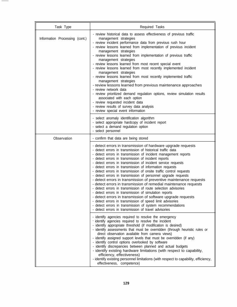
Task Type
Information Processing (cont.)
Observation
Required Tasks
- review historical data to assess effectiveness of previous trafficmanagement strategies
- review incident performance data from previous rush hour- review lessons learned from implementation of previous incident
management strategies- review lessons learned from implementation of previous traffic
management strategies- review lessons learned from most recent special event- review lessons learned from most recently implemented incident
management strategies- review lessons learned from most recently implemented traffic
management strategies- review lessons learned from previous maintenance approaches- review network data- review prioritized demand regulation options, review simulation results
associated with each option- review requested incident data- review results of survey data analysis- review special event information
- select anomaly identification algorithm- select appropriate hardcopy of incident report- select a demand regulation option- select personnel
- confirm that data are being stored
- detect errors in transmission of hardware upgrade requests- detect errors in transmission of historical traffic data- detect errors in transmission of incident management reports- detect errors in transmission of incident reports- detect errors in transmission of incident service requests- detect errors in transmission of information requests- detect errors in transmission of onsite traffic control requests- detect errors in transmission of personnel upgrade requests- detect errors in transmission of preventive maintenance requests- detect errors in transmission of remedial maintenance requests- detect errors in transmission of route selection advisories- detect errors in transmission of simulation reports- detect errors in transmission of software upgrade requests- detect errors in transmission of speed limit advisories- detect errors in transmission of system recommendations- detect errors in transmission of travel advisories
- identify agencies required to resolve the emergency- identify agencies required to resolve the incident- identify appropriate threshold (if modification is desired)- identify assessments that must be overridden (through heuristic rules or
direct observation available from camera views)- identify assigned support levels that must be overridden (if any)- identify control options overlooked by software- identify discrepancies between planned and actual budgets- identify existing hardware limitations (with respect to capability,
efficiency, effectiveness)- identify existing personnel limitations (with respect to capability, efficiency,
effectiveness, competence)
129
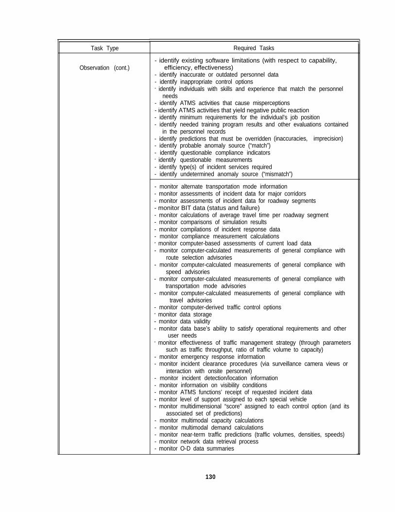
Task Type
Observation (cont.)
Required Tasks
- identify existing software limitations (with respect to capability,efficiency, effectiveness)
- identify inaccurate or outdated personnel data- identify inappropriate control options- identify individuals with skills and experience that match the personnel
needs- identify ATMS activities that cause misperceptions- identify ATMS activities that yield negative public reaction- identify minimum requirements for the individual’s job position- identify needed training program results and other evaluations contained
in the personnel records- identify predictions that must be overridden- identify probable anomaly source (“match”)- identify questionable compliance indicators- identify questionable measurements- identify type(s) of incident services required
(inaccuracies, imprecision)
- identify undetermined anomaly source (“mismatch”)
- monitor alternate transportation mode information- monitor assessments of incident data for major corridors- monitor assessments of incident data for roadway segments- monitor BIT data (status and failure)- monitor calculations of average travel time per roadway segment- monitor comparisons of simulation results- monitor compilations of incident response data- monitor compliance measurement calculations- monitor computer-based assessments of current load data- monitor computer-calculated measurements of general compliance with
route selection advisories- monitor computer-calculated measurements of general compliance with
speed advisories- monitor computer-calculated measurements of general compliance with
transportation mode advisories- monitor computer-calculated measurements of general compliance with
travel advisories- monitor computer-derived traffic control options- monitor data storage- monitor data validity- monitor data base’s ability to satisfy operational requirements and other
user needs- monitor effectiveness of traffic management strategy (through parameters
such as traffic throughput, ratio of traffic volume to capacity)- monitor emergency response information- monitor incident clearance procedures (via surveillance camera views or
interaction with onsite personnel)- monitor incident detection/location information- monitor information on visibility conditions- monitor ATMS functions’ receipt of requested incident data- monitor level of support assigned to each special vehicle- monitor multidimensional “score” assigned to each control option (and its
associated set of predictions)- monitor multimodal capacity calculations- monitor multimodal demand calculations- monitor near-term traffic predictions (traffic volumes, densities, speeds)- monitor network data retrieval process- monitor O-D data summaries
130
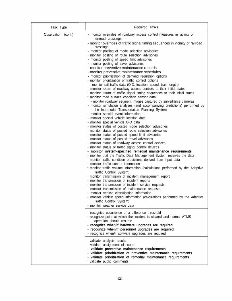
Task Type Required Tasks
Observation (cont.) - monitor overrides of roadway access control measures in vicinity ofrailroad crossings
- monitor overrides of traffic signal timing sequences in vicinity of railroadcrossings
- monitor posting of mode selection advisories - monitor posting of route selection advisories
- monitor posting of speed limit advisories- monitor posting of travel advisories- monitor preventive maintenance records- monitor preventive maintenance schedules- monitor prioritization of demand regulation options
- monitor prioritization of traffic control options - monitor rail traffic data (O-D, location, speed, train length)
- monitor return of roadway access controls to their initial states - monitor return of traffic signal timing sequences to their initial states - monitor road surface condition sensor data - monitor roadway segment images captured by surveillance cameras
- monitor simulation analyses (and accompanying predictions) performed bythe Intermodal Transportation Planning System
- monitor special event information- monitor special vehicle location data- monitor special vehicle O-D data- monitor status of posted mode selection advisories- monitor status of posted route selection advisories- monitor status of posted speed limit advisories- monitor status of posted travel advisories- monitor status of roadway access control devices- monitor status of traffic signal control devices- monitor system-specified remedial maintenance requirements- monitor that the Traffic Data Management System receives the data- monitor traffic condition predictions derived from input data- monitor traffic control information- monitor traffic volume information (calculations performed by the Adaptive
Traffic Control System)- monitor transmission of incident management report- monitor transmission of incident reports- monitor transmission of incident service requests- monitor transmission of maintenance requests- monitor vehicle classification information- monitor vehicle speed information (calculations performed by the Adaptive
Traffic Control System)- monitor weather service data
- recognize occurrence of a difference threshold- recognize point at which the incident is cleared and normal ATMS
operation should resume- recognize when/if hardware upgrades are required- recognize when/if personnel upgrades are required- recognize when/if software upgrades are required
- validate analysis results- validate assignment of scores- validate preventive maintenance requirements- validate prioritization of preventive maintenance requirements- validate prioritization of remedial maintenance requirements- validate public comments
131
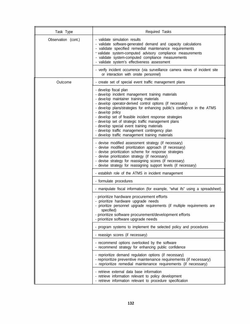
Task Type Required Tasks
Observation (cont.) - validate simulation results- validate software-generated demand and capacity calculations- validate specified remedial maintenance requirements- validate system-computed advisory compliance measurements- validate system-computed compliance measurements- validate system’s effectiveness assessment
- verify incident occurrence (via surveillance camera views of incident siteor interaction with onsite personnel)
Outcome - create set of special event traffic management plans
- deve- deve- deve- deve- deve- deve- deve- deve- deve- deve- deve
lop fiscal planlop incident management training materialslop maintainer training materialslop operator-derived control options (if necessary)lop plans/strategies for enhancing public’s confidence in the ATMSlop policylop set of feasible incident response strategieslop set of strategic traffic management planslop special event training materialslop traffic management contingency planlop traffic management training materials
- devise modified assessment strategy (if necessary)- devise modified prioritization approach (if necessary)- devise prioritization scheme for response strategies- devise prioritization strategy (if necessary)- devise strategy for reassigning scores (if necessary)- devise strategy for reassigning support levels (if necessary)
- establish role of the ATMS in incident management
- formulate procedures
- manipulate fiscal information (for example, “what ifs” using a spreadsheet)
- prioritize hardware procurement efforts- prioritize hardware upgrade needs- prioritize personnel upgrade requirements (if multiple requirements are
specified)- prioritize software procurement/development efforts- prioritize software upgrade needs
- program systems to implement the selected policy and procedures
- reassign scores (if necessary)
- recommend options overlooked by the software- recommend strategy for enhancing public confidence
- reprioritize demand regulation options (if necessary)- reprioritize preventive maintenance requirements (if necessary)- reprioritize remedial maintenance requirements (if necessary)
- retrieve external data base information- retrieve information relevant to policy development- retrieve information relevant to procedure specification
132
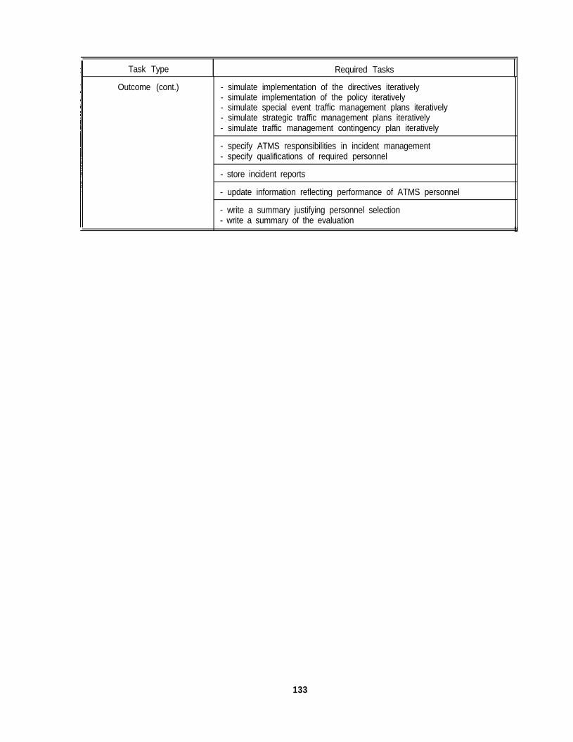
Task Type Required Tasks
Outcome (cont.) - simulate implementation of the directives iteratively- simulate implementation of the policy iteratively- simulate special event traffic management plans iteratively- simulate strategic traffic management plans iteratively- simulate traffic management contingency plan iteratively
- specify ATMS responsibilities in incident management- specify qualifications of required personnel
- store incident reports
- update information reflecting performance of ATMS personnel
- write a summary justifying personnel selection- write a summary of the evaluation
133


APPENDIX F.BREAKDOWN OF RELATED TASKS BY TASK TYPE
Task Type
Communications
Related Tasks
- consult probe vehicle operators- consult Incident Response Advisory System- consult Intermodal Transportation Planning System- consult Maintenance Tracking System- consult onsite personnel- consult Traffic Data Management System- consult Traffic Management Training System
- contact personnel selected
- ensure the users that required data are available
- exchange information needed to develop transportation plans
- hand-deliver memoranda documenting removal of hardcopies ofincident reports
- mail memoranda documenting removal of hardcopies of incidentreports
- notify special services of incident clearance via telephone or radio
- operate appropriate communications channels
- provide electronic incident response reports- provide electronic reports specifying incident service requirements (via
Traffic Data Management System)- provide verbal ATMS responsibility reports- provide verbal reports specifying incident service requirements- provide verbal (telephone, radio) incident response reports- provide written incident response reports- provide written ATMS responsibility reports- provide written reports specifying incident service requirements
- receive budget tracking information- receive Communications Support System information- receive computer reports of anomalies- receive contingency information from sources external to the ATMS- receive current policy/procedure specifications- receive electronic incident clearance reports- receive electronic incident reports- receive electronic incident/traffic information from Adaptive Traffic
Control System- receive electronic incident/traffic information from Incident Detection
and Location System- receive electronic incident/traffic information from Predictive Traffic
Modeling System- receive electronic incident/traffic information from Traffic Data
Management System- receive electronic mail notification of incident service needs- receive electronic mail notification of need for historical traffic data- receive electronic mail notification of need for incident management
report- receive electronic mail notifications of need for incident reports
135

Task Type
Communications (cont.)
Related Tasks
- receive electronic mail notifications of preventive maintenanceneeds
- receive electronic mail notification of remedial maintenance needs I- receive electronic mail notifications of system upgrade
requirements- receive electronic mail request for information- receive electronic mail request for onsite traffic control- receive electronic notification of need for public relations information- receive electronic notification of need for simulation reports- receive electronic notification of need for system recommendations- receive electronic policy statements- receive electronic procedures- receive electronic responsibility reports- receive electronic survey data- receive emergency status reports- receive fiscal information- receive hardware upgrade policy statements- receive hardware upgrade procedures- receive historical advisory compliance data- receive incident reports based on electronic and hardcopy information- receive incident response reports- receive incident status reports- receive information on traffic anomaly sources- receive information provided by the Incident Response Advisory
System- receive information that may be helpful for creating special event traffic
management plans- receive information that may be helpful for creating strategic traffic
management plans- receive multimodal capacity calculations- receive multimodal capacity data- receive multimodal demand calculations- receive multimodal demand data- receive notification of incidents- receive personnel selection decisions and evaluations- receive personnel upgrade policy statements- receive personnel upgrade procedures- receive planning functions and policy decisions relevant to procedure
specification- receive prioritized multimodal demand regulation options- receive requests to perform data base management- receive software upgrade policy statements- receive software upgrade procedures- receive survey data- receive survey results- receive traffic control information- receive Traffic Data Management System information- receive verbal assessment of ATMS hardware- receive verbal assessments of ATMS personnel- receive verbal assessments of ATMS software- receive verbal requests for hardcopies of incident reports- receive verbal (telephone, radio) incident/traffic information- receive video incident data- receive video information on incident clearance activities- receive voice-based policy statements
136

Task Type
Communications (cont.)
Related Tasks
- receive voice-based procedural information- receive voice-based responsibility reports- receive voice-based (telephone, radio) information on incident
clearance activities- receive voice (telephone, radio) communication from incident
responders- receive voice (telephone, radio) notifications of incident service needs- receive voice (telephone, radio) notifications of need for historical traffic
data- receive voice (telephone, radio) notifications of need for incident
reports- receive voice (telephone, radio) notifications of need for incident
management report- receive voice (telephone, radio) notifications of preventive
maintenance needs- receive voice (telephone, radio) notifications of remedial
maintenance needs- receive voice (telephone, radio) notifications of system
upgrade requirements- receive voice (telephone, radio) request for information- receive voice (telephone, radio) request for on-site traffic control- receive written assessment of ATMS hardware- receive written assessments of ATMS personnel- receive written assessments of ATMS software- receive written (hardcopy) notification of incident service needs- receive written (hardcopy) notification of need for historical traffic data- receive written (hardcopy) notifications of preventive maintenance
needs- receive written (hardcopy) notifications of remedial maintenance
needs- receive written (hardcopy) notifications of system upgrade
requirements- receive written (hardcopy) notifications of the need for incident reports- receive written (hardcopy) notifications of the need for an incident
management report- receive written (hardcopy) request for information- receive written (hardcopy) request for on-site traffic control- receive written incident reports- receive written incident/traffic information- receive written policy statements- receive written procedural information- receive written reports and plans relevant to policy development,- receive written requests for hardcopies of incident reports- receive written responsibility reports- receive written survey data
- record component status information into electronic data base- record emergency response report via telephone or radio
communication- record hardware upgrade request- record incident report via telephone or radio communication- record incident response information via telephone or radio
communication- record incident service request- record information request
137
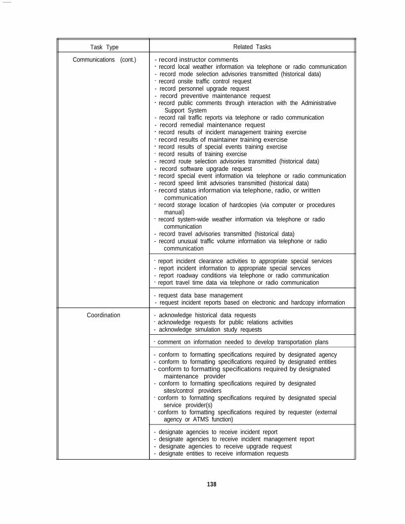
Task Type
Communications (cont.)
Related Tasks
- record instructor comments- record local weather information via telephone or radio communication- record mode selection advisories transmitted (historical data)- record onsite traffic control request- record personnel upgrade request- record preventive maintenance request- record public comments through interaction with the Administrative
Support System- record rail traffic reports via telephone or radio communication- record remedial maintenance request- record results of incident management training exercise- record results of maintainer training exercise- record results of special events training exercise- record results of training exercise- record route selection advisories transmitted (historical data)- record software upgrade request- record special event information via telephone or radio communication- record speed limit advisories transmitted (historical data)- record status information via telephone, radio, or written
communication- record storage location of hardcopies (via computer or procedures
manual)- record system-wide weather information via telephone or radio
communication- record travel advisories transmitted (historical data)- record unusual traffic volume information via telephone or radio
communication
Coordination
- report incident clearance activities to appropriate special services- report incident information to appropriate special services- report roadway conditions via telephone or radio communication- report travel time data via telephone or radio communication
- request data base management- request incident reports based on electronic and hardcopy information
- acknowledge historical data requests- acknowledge requests for public relations activities- acknowledge simulation study requests
- comment on information needed to develop transportation plans
- conform to formatting specifications required by designated agency- conform to formatting specifications required by designated entities- conform to formatting specifications required by designated
maintenance provider- conform to formatting specifications required by designated
sites/control providers- conform to formatting specifications required by designated special
service provider(s)- conform to formatting specifications required by requester (external
agency or ATMS function)
- designate agencies to receive incident report- designate agencies to receive incident management report- designate agencies to receive upgrade request- designate entities to receive information requests
138

Task Type
Coordination (cont.)
Related Tasks
- designate maintenance provider(s)- designate special service provider(s) to receive incident service request- designate sites to receive control requests- designate type of traffic control to be implemented
- interact with Administrative Support System- interact with users and computer data base software to decide how
data will be represented in data base- interact with users and computer data base software to specify what
information is stored in data base
- meet and/or communicate with people in ATMS and other agenciesinvolved in transportation planning
- share budget tracking summary with other individuals and agencies- share fiscal plan with other individuals and agencies- share justification summary with appropriate administrators- share special event traffic management strategy with other individuals
and agencies- share summary with appropriate administrators- share traffic management strategy with other individuals and agencies- share transportation plans with other individuals and agencies
Decision-Making - assign mode selection advisories to appropriate information outlets- assign route selection advisories to appropriate information outlets- assign speed limit advisories to appropriate information outlets- assign travel advisories to appropriate information outlets
- decide if storage of incident reports (hardcopies) is required- decide where to store hardcopies of incident reports
- determine access strategy to be used for data retrieval- determine if “new hires” are required- determine if requester is an external agency or an ATMS function- determine means by which established policy and procedures are to be
effected- determine whether information is consistent with ATMS budget- determine whether software products should be procured or
developed- determine whether special events trainee’s performance meets criteria
for successful performance
- distinguish between rail traffic data requiring immediate response anddata that are less urgent
- distinguish roadway conditions requiring immediate response fromthose that are less urgent
- implement backup and archiving strategy
- initiate alternative clearance procedures (if current procedures areineffective)
- match mode selection advisories to appropriate network locations- match route selection advisories to appropriate network locations- match speed limit advisories to appropriate network locations- match travel advisories to appropriate network locations
- set criteria for successful incident management trainee performance
139

Task Type
Decision-Making (cont.)
Related Tasks
- set criteria for successful maintainer trainee performance- set criteria for successful special events trainee performance- set criteria for successful traffic management trainee performance
Information Processing - apply heuristic rules
- assess budget data- assess policy and planning decisions in order to identify personnel
requirements- assess procedures’ effectiveness in resolving incident- assess relevant specifications of current policy and procedures- assess validity of directives
- assimilate alternate transportation mode information- assimilate information describing emergency response- assimilate information describing incident response- assimilate public comments- assimilate special event data
- compare planned budget to actual ATMS budget
- define backup and archiving strategy
- evaluate effectiveness of instructions in resolving incident- evaluate effect(s) of incident on traffic flow- evaluate information reflecting performance of ATMS personnel
- interpret historical data requests (identifying historical data required)- interpret results of incident management trainee performance- interpret results of maintainer trainee performance- interpret results of special events trainee performance- interpret results of traffic management trainee performance- interpret simulation analysis requests (identifying type of
analyses/reports required)
- respond to changes in requirements
- review assessments of traffic management system effectiveness(provided by Traffic Data Management System)
- review directives- review incident data- review incident detection and location information- review incident management data- review incident performance data from previous rush hour- review information available from Incident Response Advisory System- review instructions to transmit incident reports- review instructions to transmit incident management reports- review personnel records available within Administrative Support
System- review public comments- review roadway access control measures required by optimal control
scheme- review software-generated comparisons between detected anomaly’s
characteristics and characteristics of anomalies whose sources havebeen established
- review traffic control information- review traffic prediction information
140
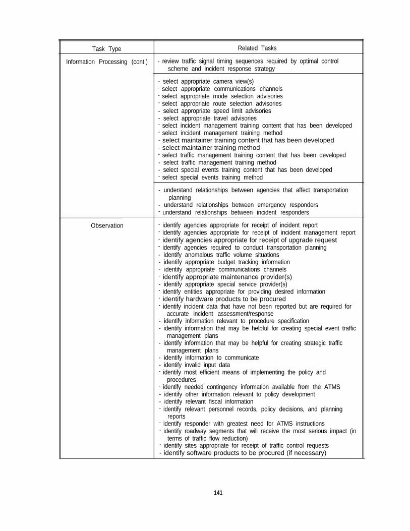
Task Type Related Tasks
Information Processing (cont.) - review traffic signal timing sequences required by optimal controlscheme and incident response strategy
- select appropriate camera view(s)- select appropriate communications channels- select appropriate mode selection advisories- select appropriate route selection advisories- select appropriate speed limit advisories- select appropriate travel advisories- select incident management training content that has been developed- select incident management training method- select maintainer training content that has been developed- select maintainer training method- select traffic management training content that has been developed- select traffic management training method- select special events training content that has been developed- select special events training method
- understand relationships between agencies that affect transportationplanning
Observation
- understand relationships between emergency responders- understand relationships between incident responders
- identify agencies appropriate for receipt of incident report- identify agencies appropriate for receipt of incident management report- identify agencies appropriate for receipt of upgrade request- identify agencies required to conduct transportation planning- identify anomalous traffic volume situations- identify appropriate budget tracking information- identify appropriate communications channels- identify appropriate maintenance provider(s)- identify appropriate special service provider(s)- identify entities appropriate for providing desired information- identify hardware products to be procured- identify incident data that have not been reported but are required for
accurate incident assessment/response- identify information relevant to procedure specification- identify information that may be helpful for creating special event traffic
management plans- identify information that may be helpful for creating strategic traffic
management plans- identify information to communicate- identify invalid input data- identify most efficient means of implementing the policy and
procedures- identify needed contingency information available from the ATMS- identify other information relevant to policy development- identify relevant fiscal information- identify relevant personnel records, policy decisions, and planning
reports- identify responder with greatest need for ATMS instructions- identify roadway segments that will receive the most serious impact (in
terms of traffic flow reduction)- identify sites appropriate for receipt of traffic control requests- identify software products to be procured (if necessary)
141
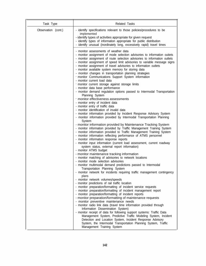
Task Type
Observation (cont.)
Related Tasks
- identify specifications relevant to those policies/procedures to beimplemented
- identify types of activities appropriate for given request- identify types of information appropriate for public distribution- identify unusual (inordinately long, excessively rapid) travel times
- monitor assessments of weather data- monitor assignment of mode selection advisories to information outiets- monitor assignment of route selection advisories to information outlets- monitor assignment of speed limit advisories to variable message signs- monitor assignment of travel advisories to information outlets- monitor available system memory for storing data- monitor changes in transportation planning strategies- monitor Communications Support System information- monitor current load data- monitor current storage against storage limits- monitor data base performance- monitor demand regulation options passed to Intermodal Transportation
Planning System- monitor effectiveness assessments- monitor entry of incident data- monitor entry of traffic data- monitor identification of invalid data- monitor information provided by Incident Response Advisory System- monitor information provided by Intermodal Transportation Planning
System- monitor information provided by Maintenance Tracking System- monitor information provided by Traffic Management Training System- monitor information provided to Traffic Management Training System- monitor information reflecting performance of ATMS personnel- monitor information response reports- monitor input information (current load assessment, current roadway
system status, external report information)- monitor ATMS budget- monitor maintenance tracking information- monitor matching of advisories to network locations- monitor mode selection advisories- monitor multimodal demand predictions passed to Intermodal
Transportation Planning System- monitor network for incidents requiring traffic management contingency
plans- monitor network volumes/speeds- monitor predictions of rail traffic location- monitor preparation/formatting of incident service requests- monitor preparation/formatting of incident management report- monitor preparation/formatting of incident reports- monitor preparation/formatting of maintenance requests- monitor preventive maintenance needs- monitor radio link data (travel time information provided through
Information Dissemination System)- monitor receipt of data for following support systems: Traffic Data
Management System, Predictive Traffic Modeling System, IncidentDetection and Location System, Incident Response AdvisorySystem, the Intermodal Transportation Planning System, TrafficManagement Training System
142

Task Type Related Tasks
Observation (cont.)
Outcome
- monitor receipt of historical incident data requests- monitor remedial maintenance needs (for electronic components)- monitor remedial maintenance schedules- monitor reports indicating preventive maintenance needs- monitor reports indicating remedial maintenance needs- monitor roadway condition reports- monitor simulation results passed to Intermodal Transportation
Planning System- monitor status of roadway conditions (for maintenance purposes)- monitor system component evaluations- monitor system’s responses to weather data- monitor traffic prediction information- monitor Traffic Data Management System information- monitor vehicle locations (maintained by Traffic Data Management
System)- monitor vehicle movement reports- monitor vehicle occupancy information (from surveillance cameras)- monitor vehicle speeds (maintained by Traffic Data Management
System)- monitor violations of potential vehicle-type restrictions
- observe incident site- observe road images via surveillance cameras
- recognize data link failures- recognize formatting requirements for each route selection advisory- recognize formatting requirements for each speed limit advisory- recognize formatting requirements for each travel advisory- recognize formatting requirements for each mode selection advisory- recognize potentially severe weather patterns- recognize type of historical traffic data required- recognize type of public relations information required- recognize type of simulation report required- recognize type of system recommendations required
- validate alternate transportation mode information- validate component status report- validate incident information- validate information describing emergency response- validate information describing incident response- validate input information- validate rail traffic data II- validate roadway condition reports- validate special event data- validate traffic volume reports- validate travel time reports- validate visibility condition information- validate weather reports
- verify incident reports using other information sources
- view video scenes from surveillance cameras
- access historical data- access historical traffic data- access public relations information- access simulation report
143
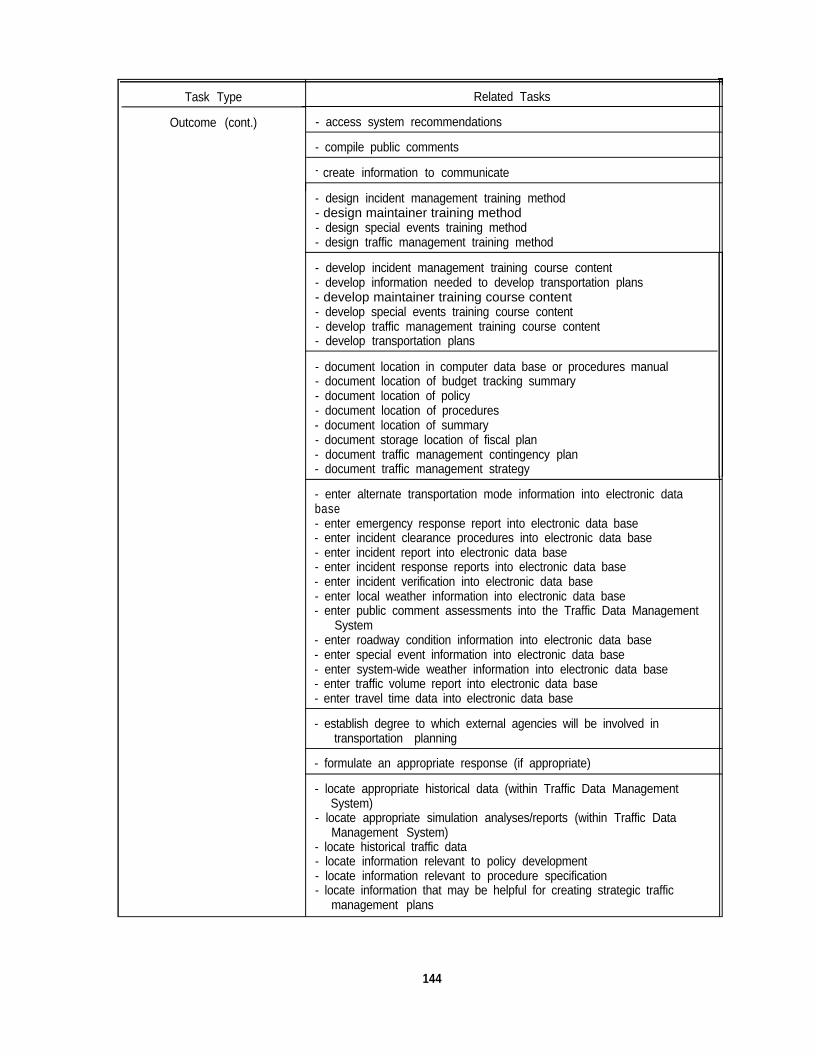
Task Type
Outcome (cont.)
Related Tasks
- access system recommendations
- compile public comments
- create information to communicate
- design incident management training method- design maintainer training method- design special events training method- design traffic management training method
- develop incident management training course content- develop information needed to develop transportation plans- develop maintainer training course content- develop special events training course content- develop traffic management training course content- develop transportation plans
- document location in computer data base or procedures manual- document location of budget tracking summary- document location of policy- document location of procedures- document location of summary- document storage location of fiscal plan- document traffic management contingency plan- document traffic management strategy
- enter alternate transportation mode information into electronic database- enter emergency response report into electronic data base- enter incident clearance procedures into electronic data base- enter incident report into electronic data base- enter incident response reports into electronic data base- enter incident verification into electronic data base- enter local weather information into electronic data base- enter public comment assessments into the Traffic Data Management
System- enter roadway condition information into electronic data base- enter special event information into electronic data base- enter system-wide weather information into electronic data base- enter traffic volume report into electronic data base- enter travel time data into electronic data base
- establish degree to which external agencies will be involved intransportation planning
- formulate an appropriate response (if appropriate)
- locate appropriate historical data (within Traffic Data ManagementSystem)
- locate appropriate simulation analyses/reports (within Traffic DataManagement System)
- locate historical traffic data- locate information relevant to policy development- locate information relevant to procedure specification- locate information that may be helpful for creating strategic traffic
management plans
144
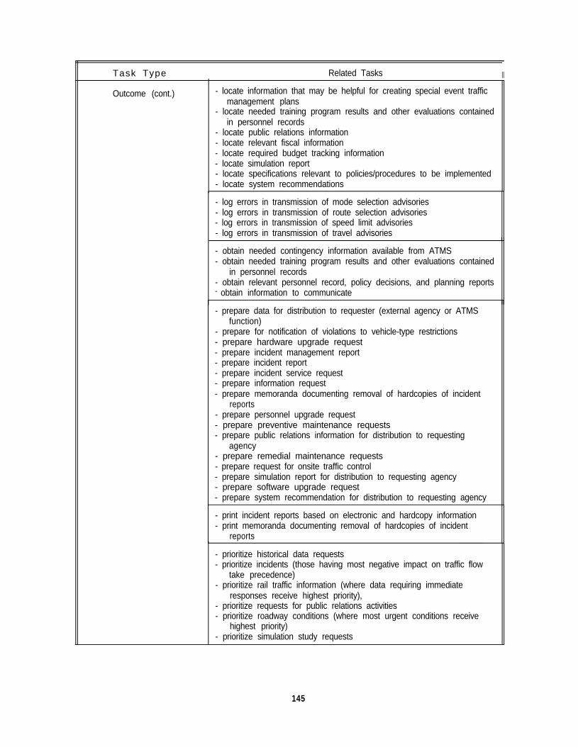
Task Type Related Tasks II
Outcome (cont.) - locate information that may be helpful for creating special event trafficmanagement plans
- locate needed training program results and other evaluations containedin personnel records
- locate public relations information- locate relevant fiscal information- locate required budget tracking information- locate simulation report- locate specifications relevant to policies/procedures to be implemented- locate system recommendations
- log errors in transmission of mode selection advisories- log errors in transmission of route selection advisories- log errors in transmission of speed limit advisories- log errors in transmission of travel advisories
- obtain needed contingency information available from ATMS- obtain needed training program results and other evaluations contained
in personnel records- obtain relevant personnel record, policy decisions, and planning reports- obtain information to communicate
- prepare data for distribution to requester (external agency or ATMSfunction)
- prepare for notification of violations to vehicle-type restrictions- prepare hardware upgrade request- prepare incident management report- prepare incident report- prepare incident service request- prepare information request- prepare memoranda documenting removal of hardcopies of incident
reports- prepare personnel upgrade request- prepare preventive maintenance requests- prepare public relations information for distribution to requesting
agency- prepare remedial maintenance requests- prepare request for onsite traffic control- prepare simulation report for distribution to requesting agency- prepare software upgrade request- prepare system recommendation for distribution to requesting agency
- print incident reports based on electronic and hardcopy information- print memoranda documenting removal of hardcopies of incident
reports
- prioritize historical data requests- prioritize incidents (those having most negative impact on traffic flow
take precedence)- prioritize rail traffic information (where data requiring immediate
responses receive highest priority),- prioritize requests for public relations activities- prioritize roadway conditions (where most urgent conditions receive
highest priority)- prioritize simulation study requests
145

APPENDIX G.BREAKDOWN OF REQUIRED MAINTENANCE TASKS BY TASK TYPE
Task Type
Communications
Maintenance Tasks
- issue electronic mail request for preventive maintenance- issue electronic mail request for remedial maintenance- issue voice (telephone, radio) request for pre-positioning of
maintenance assets- issue voice (telephone, radio) request for preventive maintenance- issue voice (telephone, radio) request for remedial maintenance- issue written (hardcopy) request for preventive maintenance- issue written (hardcopy) request for remedial maintenance- issue written (hardcopy, electronic mail) request for hardware
upgrade- issue written (hardcopy, electronic mail) request for software
upgrade
- receive voice-based (telephone, radio) component status report- receive written component status report
- report hardware upgrade requirements- report software upgrade requirements
- retransmit hardware upgrade request- retransmit preventive maintenance request- retransmit remedial maintenance request- retransmit software upgrade request
Coordination
Decision-Making
- conduct maintainer training
- determine whether maintainer trainee’s performance meets criteriafor successful performance
- modify preventive maintenance requirements (if necessary)- modify remedial maintenance requirements (if necessary)
Information Processing - analyze maintainer training requirements
- review lessons learned from previous maintenance approaches
Observation - detect errors in transmission of hardware upgrade requests- detect errors in transmission of preventive maintenance requests- detect errors in transmission of remedial maintenance requests- detect errors in transmission of software upgrade requests
- identify existing hardware limitations (with respect to capability,efficiency, effectiveness)
- identify existing software limitations (with respect to power,efficiency, effectiveness)
- monitor BIT data (status and failure)- monitor preventive maintenance records- monitor preventive maintenance schedule- monitor system-specified remedial maintenance requirements- monitor transmission of maintenance requests
- recognize when/if hardware upgrades are required- recognize when/if software upgrades are required
147
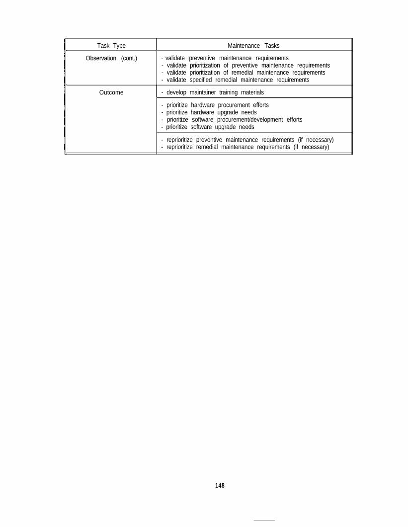
Task Type Maintenance Tasks
Observation (cont.) - validate preventive maintenance requirements- validate prioritization of preventive maintenance requirements- validate prioritization of remedial maintenance requirements- validate specified remedial maintenance requirements
Outcome - develop maintainer training materials
- prioritize hardware procurement efforts- prioritize hardware upgrade needs- prioritize software procurement/development efforts- prioritize software upgrade needs
- reprioritize preventive maintenance requirements (if necessary)- reprioritize remedial maintenance requirements (if necessary)
148
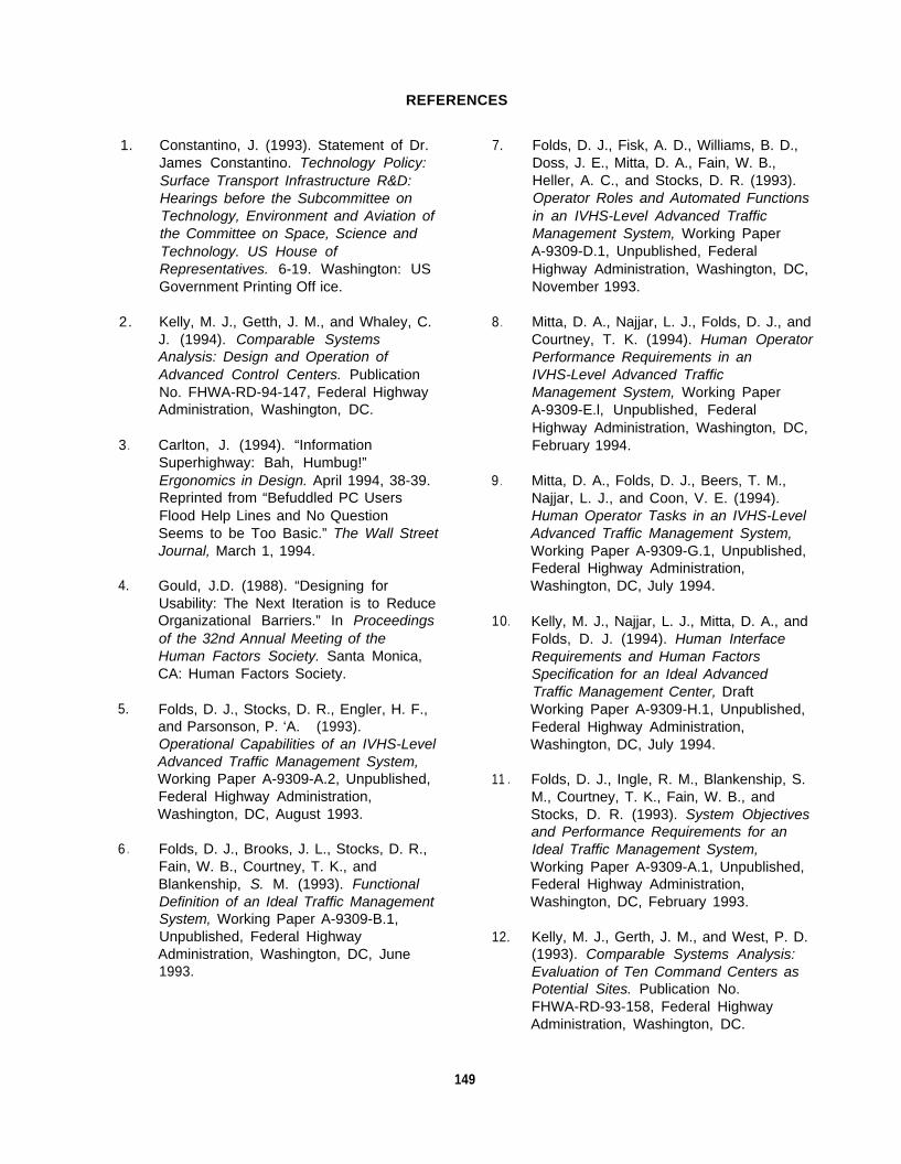
REFERENCES
1.
2.
3 .
4.
5.
6 .
Constantino, J. (1993). Statement of Dr.James Constantino. Technology Policy:Surface Transport Infrastructure R&D:Hearings before the Subcommittee onTechnology, Environment and Aviation ofthe Committee on Space, Science andTechnology. US House ofRepresentatives. 6-19. Washington: USGovernment Printing Off ice.
Kelly, M. J., Getth, J. M., and Whaley, C.J. (1994). Comparable SystemsAnalysis: Design and Operation ofAdvanced Control Centers. PublicationNo. FHWA-RD-94-147, Federal HighwayAdministration, Washington, DC.
Carlton, J. (1994). “InformationSuperhighway: Bah, Humbug!”Ergonomics in Design. April 1994, 38-39.Reprinted from “Befuddled PC UsersFlood Help Lines and No QuestionSeems to be Too Basic.” The Wall StreetJournal, March 1, 1994.
Gould, J.D. (1988). “Designing forUsability: The Next Iteration is to ReduceOrganizational Barriers.” In Proceedingsof the 32nd Annual Meeting of theHuman Factors Society. Santa Monica,CA: Human Factors Society.
Folds, D. J., Stocks, D. R., Engler, H. F.,and Parsonson, P. ‘A. (1993).Operational Capabilities of an IVHS-LevelAdvanced Traffic Management System,Working Paper A-9309-A.2, Unpublished,Federal Highway Administration,Washington, DC, August 1993.
Folds, D. J., Brooks, J. L., Stocks, D. R.,Fain, W. B., Courtney, T. K., andBlankenship, S. M. (1993). FunctionalDefinition of an Ideal Traffic ManagementSystem, Working Paper A-9309-B.1,Unpublished, Federal HighwayAdministration, Washington, DC, June1993.
7. Folds, D. J., Fisk, A. D., Williams, B. D.,Doss, J. E., Mitta, D. A., Fain, W. B.,Heller, A. C., and Stocks, D. R. (1993).Operator Roles and Automated Functions
in an IVHS-Level Advanced TrafficManagement System, Working PaperA-9309-D.1, Unpublished, FederalHighway Administration, Washington, DC,November 1993.
8 . Mitta, D. A., Najjar, L. J., Folds, D. J., andCourtney, T. K. (1994). Human OperatorPerformance Requirements in anIVHS-Level Advanced TrafficManagement System, Working PaperA-9309-E.l, Unpublished, FederalHighway Administration, Washington, DC,February 1994.
9 . Mitta, D. A., Folds, D. J., Beers, T. M.,Najjar, L. J., and Coon, V. E. (1994).Human Operator Tasks in an IVHS-LevelAdvanced Traffic Management System,Working Paper A-9309-G.1, Unpublished,Federal Highway Administration,Washington, DC, July 1994.
10. Kelly, M. J., Najjar, L. J., Mitta, D. A., andFolds, D. J. (1994). Human InterfaceRequirements and Human FactorsSpecification for an Ideal AdvancedTraffic Management Center, DraftWorking Paper A-9309-H.1, Unpublished,Federal Highway Administration,Washington, DC, July 1994.
11 . Folds, D. J., Ingle, R. M., Blankenship, S.M., Courtney, T. K., Fain, W. B., andStocks, D. R. (1993). System Objectivesand Performance Requirements for anIdeal Traffic Management System,Working Paper A-9309-A.1, Unpublished,Federal Highway Administration,Washington, DC, February 1993.
12. Kelly, M. J., Gerth, J. M., and West, P. D.(1993). Comparable Systems Analysis:Evaluation of Ten Command Centers asPotential Sites. Publication No.FHWA-RD-93-158, Federal HighwayAdministration, Washington, DC.
149
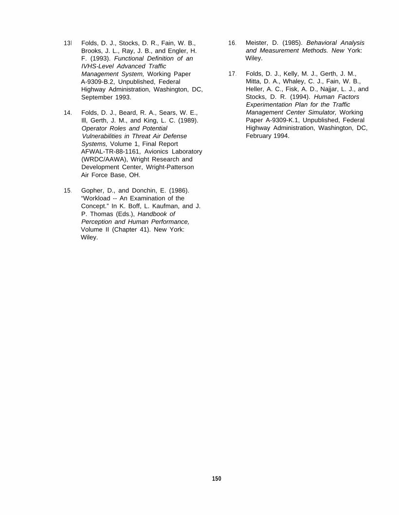
13l Folds, D. J., Stocks, D. R., Fain, W. B.,Brooks, J. L., Ray, J. B., and Engler, H.F. (1993). Functional Definition of anIVHS-Level Advanced TrafficManagement System, Working PaperA-9309-B.2, Unpublished, FederalHighway Administration, Washington, DC,September 1993.
14. Folds, D. J., Beard, R. A., Sears, W. E.,Ill, Gerth, J. M., and King, L. C. (1989).Operator Roles and PotentialVulnerabilities in Threat Air DefenseSystems, Volume 1, Final ReportAFWAL-TR-88-1161, Avionics Laboratory(WRDC/AAWA), Wright Research andDevelopment Center, Wright-PattersonAir Force Base, OH.
15. Gopher, D., and Donchin, E. (1986).“Workload -- An Examination of theConcept.” In K. Boff, L. Kaufman, and J.P. Thomas (Eds.), Handbook ofPerception and Human Performance,Volume II (Chapter 41). New York:Wiley.
16 . Meister, D. (1985). Behavioral Analysisand Measurement Methods. New York:Wiley.
17 . Folds, D. J., Kelly, M. J., Gerth, J. M.,Mitta, D. A., Whaley, C. J., Fain, W. B.,Heller, A. C., Fisk, A. D., Najjar, L. J., andStocks, D. R. (1994). Human FactorsExperimentation Plan for the TrafficManagement Center Simulator, WorkingPaper A-9309-K.1, Unpublished, FederalHighway Administration, Washington, DC,February 1994.
150
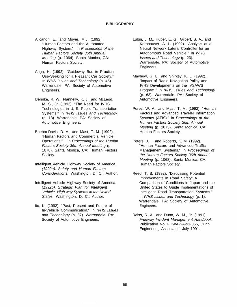
BIBLIOGRAPHY
Alicandri, E., and Moyer, M.J. (1992).“Human Factors and the AutomatedHighway System.” In Proceedings of theHuman Factors Society 36th AnnualMeeting (p. 1064). Santa Monica, CA:Human Factors Society.
Ariga, H. (1992). “Guideway Bus in PracticalUse-Seeking for a Pleasant Car Society.”In IVHS Issues and Technology (p. 45).Warrendale, PA: Society of AutomotiveEngineers.
Behnke, R. W., Flannelly, K. J., and McLeod,M. S., Jr. (1992). “The Need for IVHSTechnologies in U. S. Public TransportationSystems.” In IVHS Issues and Technology(p. 13). Warrendale, PA: Society ofAutomotive Engineers.
Boehm-Davis, D. A., and Mast, T. M. (1992).“Human Factors and Commercial VehicleOperations.” In Proceedings of the HumanFactors Society 36th Annual Meeting (p.1078). Santa Monica, CA: Human FactorsSociety.
Intelligent Vehicle Highway Society of America.(1992a). Safety and Human FactorsConsiderations. Washington D. C.: Author.
Intelligent Vehicle Highway Society of America.(1992b). Strategic Plan for IntelligentVehicle- High way Systems in the UnitedStates. Washington, D. C.: Author.
Ito, K. (1992). “Past, Present and Future ofIn-Vehicle Communication.” In IVHS Issuesand Technology (p. 57). Warrendale, PA:Society of Automotive Engineers.
Lubin, J. M., Huber, E. G., Gilbert, S. A., andKornhauser, A. L. (1992). “Analysis of aNeural Network Lateral Controller for anAutonomous Road Vehicle.” In IVHSIssues and Technology (p. 23).Warrendale, PA: Society of AutomotiveEngineers.
Mayhew, G. L., and Shirkey, K. L. (1992).“Impact of Radio Navigation Policy andIVHS Developments on the IVSAWSProgram.” In IVHS Issues and Technology(p. 63). Warrendale, PA: Society ofAutomotive Engineers.
Perez, W. A., and Mast, T. M. (1992). “HumanFactors and Advanced Traveler InformationSystems (ATIS).” In Proceedings of theHuman Factors Society 36th AnnualMeeting (p. 1073). Santa Monica, CA:Human Factors Society.
Peters, J. I., and Roberts, K. M. (1992).“Human Factors and Advanced TrafficManagement Systems.” In Proceedings ofthe Human Factors Society 36th AnnualMeeting (p. 1068). Santa Monica, CA:Human Factors Society.
Reed, T. B. (1992). “Discussing PotentialImprovements in Road Safety: AComparison of Conditions in Japan and theUnited States to Guide Implementations ofIntelligent Road Transportation Systems.”In IVHS Issues and Technology (p. 1).Warrendale, PA: Society of AutomotiveEngineers.
Reiss, R. A., and Dunn, W. M., Jr. (1991).Freeway Incident Management Handbook.Publication No. FHWA-SA-91-056, DunnEngineering Associates, July 1991.
151