design of a structure with paper tube arches
TRANSCRIPT
Construction and Building Materials 30 (2012) 657–666
Contents lists available at SciVerse ScienceDirect
Construction and Building Materials
journal homepage: www.elsevier .com/locate /conbui ldmat
Portals to an Architecture: Design of a temporary structure with paper tube arches
Steven J. Preston ⇑, Lawrence C. Bank 1
Civil and Environmental Engineering Department, University of Wisconsin-Madison, 2205 Engineering Hall, 1415 Engineering Drive, Madison, WI 53706, United States
a r t i c l e i n f o a b s t r a c t
Article history:Received 17 February 2011Received in revised form 1 December 2011Accepted 4 December 2011Available online 11 January 2012
Keywords:ArchitectureStructureEngineeringSculptureSustainabilityPaper tubes
0950-0618/$ - see front matter � 2011 Elsevier Ltd. Adoi:10.1016/j.conbuildmat.2011.12.019
⇑ Corresponding author. Address: Peter Gluck anStreet, 6th Floor, New York, NY 10027, United StaFormerly, Graduate Student of Civil Engineering, Depmental Engineering, University of Wisconsin, Madison
E-mail addresses: [email protected] (S.J. Pre(L.C. Bank).
1 Address: The City College of New York, Wille AdmiConvent Ave., New York, NY 10031, United States. TelProfessor of Civil Engineering, Department of Civil anUniversity of Wisconsin, Madison, WI 53706, United S
Sustainable recyclable paper and composite materials can be ideal choices for the construction of tempo-rary structures for both exhibition spaces or for rapid-recovery shelters in emergency operations. Theunique engineering and sustainable features of these structures need to be considered as an integral partof the design process from the conceptual phase. Engineering studies to analyze these structures shouldbe as important as the overall artistic and architectural vision. This paper examines the use of environ-mentally creep-formed paper tubes for the design, construction, and exhibition of, ‘‘Portals to an Architec-ture’’, a large temporary outdoor sculpture.
� 2011 Elsevier Ltd. All rights reserved.
1. Introduction
Recyclable paper and composite materials are excellent choicesfor the construction of temporary structures for both exhibitionspaces or for rapid-recovery shelters in emergency operations. Spe-cifically, large diameter (100 mm and greater) paper tubes (aka‘‘cores’’) used in the printing and converting industries [17] canbe used in innovative ways that take advantage of their materialproperties, recyclability, and low cost. Spirally wound paper tubesare highly engineered structural products made of different gradesof paper board [8] and are used principally in the paper and fabricindustries for supplying sheet and fiber materials. In building con-struction they are used as disposable forms for concrete columnsknown as ‘‘Sonotubes’’ [16]. Architecturally, paper tubes have beenused in column, beam, and shell type configurations for both per-manent and temporary structures. Less frequently, paper tubeshave been utilized in curved applications, which often requiresadditional structural supports.
Architect Shigeru Ban is well known for his use of paper tubes ina variety of applications [13]. Following the Hanshin-Awaji earth-
ll rights reserved.
d Partners, 423 West 127thtes. Tel.: +1 608 217 8662.artment of Civil and Environ-
, WI 53706, United States.ston), [email protected]
nistration Building, A218, 160.: +1 212 650 5143. Formerly,d Environmental Engineering,tates.
quake in 1995, Ban utilized paper tubes for the main structuralwall elements to construct temporary relief housing and a churchfor victims of the disaster. The design was further adapted and uti-lized in 2001 for relief housing in Ahmadabad, India [4], and in2010 for shelters in Haiti [2]. While suitable for permanent appli-cations, paper tubes have become popular for temporary struc-tures, largely because of their potential inventiveness andminimal environmental impact. The Nomadic Museum by Banwas a traveling temporary exhibition space which featured thephotography of Gregory Colbert. The structure combined 152 ship-ping containers and large paper tubes to create a 56,000 square-foot (5200 square-meter) space [10]. In 2008, architects from thefirm WORK Architecture Company transformed the P.S.1 courtyardinto an urban farm for their temporary installation [14]. Papertubes were the primary construction material for this ‘‘Public Farm1’’, serving as support columns, furniture, and containers for theplants and crops.
The temporary exhibition at MoMA in New York City, and theHanover pavilion in Germany, were completed by Ban in 2000[7]. The MoMA exhibition was comprised of long paper trussesspanning 80 feet (24 m). The chords of the trusses were createdfrom 6-in. to 8-in. (150–200 mm) diameter paper tubes of 1-in.(25 mm) wall thickness, while steel rods and cable elements wereutilized between the chords to provide stiffening [7]. Ban’s designfor the Hanover pavilion was a flexible grid shell structure of papertubes, and covered an area of 27,000 square-feet (2500 square-me-ters). The goal of the project was to create a structure (using low-tech construction menthols) with the smallest amount of industrialwaste possible, and to recycle or reuse all of the construction mate-rials following disassembly [3]. Due to a large amount of creep in
S.J. Preston, L.C. Bank / Construction and Building Materials 30 (2012) 657–666658
the paper tubes, a series of wooden ladder arches were constructedand tied into the paper tube grid shell [11]. During construction,the sections of the ladder arches was increased and steel reinforce-ments were added because city officials required recalculation ofthe pavilion as a rigid structure as opposed to flexible [11]. In addi-tion to paper tube bending, curved and arch shapes have also beenaccomplished by joining together small straight segments as seenin the 2007 temporary bridge designed by Ban [6]. Gently archingover the Gardon River in France, the bridge is comprised of 281recycled paper tubes and utilizes additional metal, wood, and plas-tics [6].
The case study that follows examines the use of environmen-tally creep-formed paper tubes for the construction of a large tem-porary outdoor exhibition titled, Portals to an Architecture [15]. Thesculpture was designed to have a minimal environmental impact,and exemplify different techniques and methods to design andengineer more sustainably. To that end, paper tubes were chosenas the primary structural material for the exhibition due to theirinherent recycled paper content, ability to be recycled into new pa-per tubes afterwards, and because they are a low-cost materialavailable worldwide.
Following an introduction to the case study, the mechanical andgeometrical properties of the paper tubes are described. Theseproperties were integral to the design process and largely informedthe geometry of the structure due to the limitations and con-straints of the materials, but also resulted in design opportunitiesthroughout the project. An engineering design basis is then pre-sented which applies the mechanical and geometrical propertiesof the paper tubes and other materials to the design of the struc-ture in order to meet code requirements and ensure public safety.Construction methods and techniques for the final exhibition arethen described. Finally, remarks are discussed which relate to thesustainability and environmental impact of temporary structuresas well as the need for the engineering of these structures to beintegrated throughout the design process.
2. Introduction to the case study
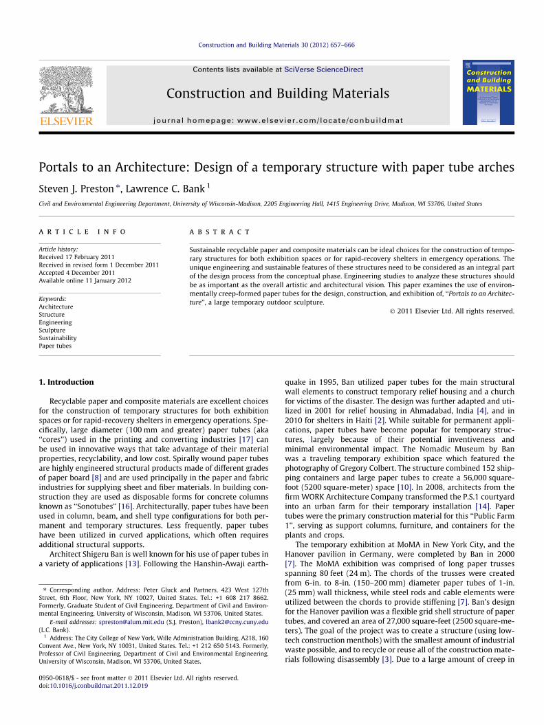
Portals to an Architecture (Fig. 1) was a temporary structure andsculpture constructed at the University of Wisconsin–Madisonconsisting of an interconnected array of 3–6-in. (75–150 mm)
Fig. 1. Image of final exhibition loo
diameter paper tube arches [15]. The sculpture utilized 100% recy-clable materials, exemplified sustainable design and constructiontechniques, and was thoroughly studied and engineered prior toinstallation and public interaction.
The Portals were constructed on the mall which extends northfrom the Engineering school, and spanned playfully across thespillway of the existing fountain. The project was then exhibitedfor the months of May and June in 2006. Afterwards, the entirestructure was disassembled and all of the materials were recycledor reused in other projects.
The Portals were designed and constructed to exemplify anddemonstrate techniques for combining sculpture, engineering,and systemic sustainability in the form of a temporary structure.There was a special focus on innovative material selection, and sus-tainability-related decision making. In addition to environmental,the project also addressed social sustainability in that it was awork constructed and exhibited in the public realm, bringing thetypically private engineering research project out of the laboratory.As a public art piece, the Portals encouraged interaction and wasopen to all. Academically, the collaboration of many different indi-viduals, departments, disciplines, local businesses, and industrysponsors allowed for the project to transcend the realm of engi-neering research into public art as well. In the end, the Portalsnot only stood alone as a finished work, but exemplified a process.
The proposal to build a temporary structure came from researchexplorations with paper tubes as a construction material. The ideato use paper tubes demanded an application that was unique andappropriate to the material. Furthermore, to push the limits ofthe material, the decision was made to focus on applicationsinvolving curved tubes which were environmentally creep-formedunder their own weight prior to use in the field. In previous arch-like structures built using paper tubes (Hanover, MoMA, etc.), thetubes have been bent in the field. This application is believed tobe the first time pre-curved creep-formed paper tubes have beenused in a structure.
The structure was designed to exemplify a design process whichfocused on sustainability and innovation. It was to be 100% recycla-ble, and have the lowest environmental impact as possible. Whilesculptural in form, the design could also be the basis for temporaryemergency structures needed for disaster relief. The final designwas realized as a series of interconnected arches that gave meta-phorical form to the internal bone cavities of the first author’s
king towards Engineering Hall.
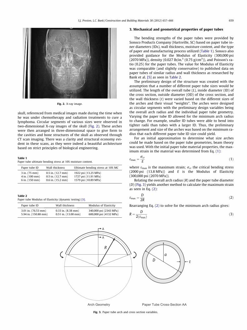
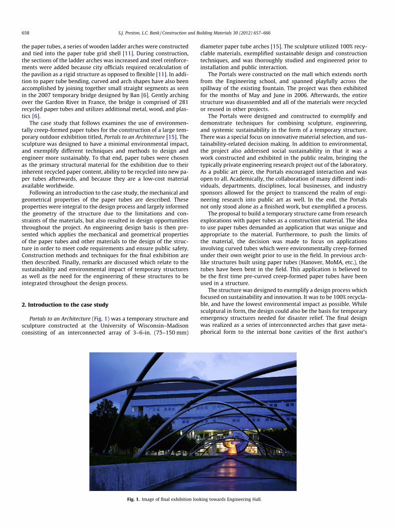
Fig. 2. X-ray image.
659S.J. Preston, L.C. Bank / Construction and Building Materials 30 (2012) 657–666
skull, referenced from medical images made during the time whenhe was under chemotherapy and radiation treatments to cure alymphoma. Circular segments of various sizes were observed intwo-dimensional X-ray images of the skull (Fig. 2). These archeswere then arranged in three-dimensional space to give form tothe cavities and bone structures of the skull as observed throughCT scan imaging. There was a clarity and structural economy evi-dent in these scans, as they were indeed a beautiful architecturebased on strict principles of biological engineering.
Table 1Paper tube ultimate bending stress at 10% moisture content.
Paper tube ID Wall thickness Ultimate bending stress at 10% MC
3 in. (75 mm) 0.5 in. (12.7 mm) 1922 psi (13.25 MPa)4 in. (100 mm) 0.5 in. (12.7 mm) 1727 psi (11.91 MPa)6 in. (150 mm) 0.6 in. (15.2 mm) 1579 psi (10.89 MPa)
Table 2Paper tube Modulus of Elasticity (dynamic testing) [5].
Paper tube ID Wall thickness Modulus of Elasticity
3.01 in. (76.53 mm) 0.33 in. (8.38 mm) 340,000 psi (2343 MPa)5.94 in. (150.88 mm) 0.51 in. (13.00 mm) 600,000 psi (4132 MPa)
Arch Geometry
Fig. 3. Paper tube arch and
3. Mechanical and geometrical properties of paper tubes
The bending strengths of the paper tubes were provided bySonoco Products Company (Hartsville, SC) based on paper tube in-ner diameters (IDs), wall thickness, moisture content, and the typeof paper and manufacturing process utilized (Table 1). Sonoco alsoprovided guidance for the Modulus of Elasticity (300,000 psi(2070 MPa)), density (0.027 lb/in.3 (0.75 g/cm3)), and Poisson’s ra-tio (0.25) for the paper tubes. The value for Modulus of Elasticitywas comparable (and slightly conservative) to published data onpaper tubes of similar radius and wall thickness as researched byBank et al. [5] as seen in Table 2.
The preliminary design of the structure was created with theassumption that a number of different paper tube sizes would beutilized. The length of the overall tube (L), inside diameter (ID) ofthe cross section, outside diameter (OD) of the cross section, andthe wall thickness (t) were varied based on the different sizes ofthe arches and their visual ‘‘weights’’. The arches were designedas circular segments with the preliminary design variables beingthe overall arch radius and the individual paper tube geometry.Varying the paper tube ID allowed for the minimum arch radiusto change. For example, smaller ID tubes were able to bend intotighter radii than tubes with a larger ID. Thus, the preliminaryarrangement and size of the arches was based on the minimum ra-dius that each different paper tube ID size could yield.
For an initial approximation to determine what size archescould be made based on the paper tube geometries, beam theorywas used. With the initial paper tube material properties, the max-imum strain in the material was determined from Eq. (1):
emax ¼rcr
Eð1Þ
where emax is the maximum strain; rcr the critical bending stress(2000 psi (13.8 MPa)) and E is the Modulus of Elasticity(300,000 psi (2070 MPa)).
Relating the overall arch radius (R) and the paper tube diameter(D) (Fig. 3) yields another method to calculate the maximum strainas seen in Eq. (2):
emax ¼D2R
ð2Þ
Rearranging Eq. (2) to solve for the minimum arch radius gives:
R ¼ D2ðemaxÞ
ð3Þ
Paper Tube Cross-Section AA
cross section variables.

S.J. Preston, L.C. Bank / Construction and Building Materials 30 (2012) 657–666660
Using the maximum strain value (0.007 or 0.7%) calculated with Eq.(1), the minimum arch radii were determined based on input of dif-ferent paper tube ID values. These initial values, as listed in Table 3,represent conservative estimates because the time dependent nat-ure of the bending process was not considered in the calculations.Thus, they were used as a starting point in the process to create afinal design.
To check for the possibility of failure due to local wall bucklingthe critical buckling stress was calculated using Eq. (4) [19] andthen converted into a maximum strain with Eq. (6):
rcr ¼Eh
affiffiffiffiffiffiffiffiffiffiffiffiffiffiffiffiffiffiffiffi3ð1� m2Þ
p ð4Þ
r ¼ Ee ð5Þ
ecr ¼h
affiffiffiffiffiffiffiffiffiffiffiffiffiffiffiffiffiffiffiffi3ð1� m2Þ
p ð6Þ
Table 3Arch radius based on approximate paper tube diameter.
Paper tube OD Minimum arch radius
3 in. (76.2 mm) 17.86 ft (5.44 m)4 in. (101.6 mm) 23.81 ft (7.26 m)5 in. (127.0 mm) 29.76 ft (9.07 m)6 in. (152.4 mm) 35.71 ft (10.88 m)7 in. (177.8 mm) 41.67 ft (12.70 m)8 in. (203.2 mm) 47.62 ft (14.51 m)9 in. (228.6 mm) 53.57 ft (16.33 m)
10 in. (254.0 mm) 59.52 ft (18.14 m)
Fig. 4. Physical test performed to observe bending in actual paper tube.
Fig. 5. Geometric a
where h is the paper tube wall thickness, inches; a the radial dis-tance from tube center to tube wall (see Fig. 3), inches; m the Pois-son’s ratio and ecr is the critical buckling strain, in./in.
Based on calculations for a 6-in. ID (150 mm) tube with a wallthickness of 0.5 in. (12.7 mm), the critical buckling stress(27,500 psi (190 MPa)) was found to be much larger than the papertube strength (1580 psi (10.9 MPa)). The critical buckling strain(9%) was also much larger than the critical strain (0.7%). Basedon these calculations, failure due to bending would occur long be-fore failure due to buckling.
The design for the individual arches was based upon the geom-etry of circular segments. Physical bending tests were performed toobserve the tubes and better understand the variability of the archshape (Fig. 4). The precise mathematic variables for circular archgeometry (Fig. 5) were calculated as follows:
Eqs. (7)–(12) relate these variables mathematically to oneanother:
s ¼ rh ð7Þ
s ¼ rhp180
ð8Þ
c ¼ 2ffiffiffiffiffiffiffiffiffiffiffiffiffiffiffir2 � d2
qð9Þ
c ¼ 2ffiffiffiffiffiffiffiffiffiffiffiffiffiffiffiffiffiffiffiffihð2r � hÞ
qð10Þ
d ¼ffiffiffiffiffiffiffiffiffiffiffiffiffiffiffiffiffiffi4r2 � c2p
2ð11Þ
d ¼ c cotðh=2Þ2
ð12Þ
where s is the arc length, feet; r the radius of circle, feet; h the angle,radians; c the chord, feet; d the apothem (distance from chord tocenter circle), feet and h is the height from chord, feet.
While designing the individual arches, it was often times conve-nient to consider a given arc length and height, and to then com-pute the remaining geometric values. Eq. (13) relates circular arclength and height from the chord of an arch:
2hs¼ ð1� cosðxÞÞ
xð13Þ
where x is the unknown variable.Newton’s method is required to solve for the unknown variable
‘x’ (Eqs. (14)–(16)):
k ¼ ð1� cosðxÞÞx
ð14Þ
rch variables.

661S.J. Preston, L.C. Bank / Construction and Building Materials 30 (2012) 657–666
k ¼ 2hs
ð15Þ
xðnþ 1Þ ¼ xðnÞ � ðcos½xðnÞ� þ knðnÞ � 1Þð� sin½xðnÞ� þ kÞ ð16Þ
Following the use of Newton’s method when ‘x’ is known,Eqs. (17)–(20) were then used to relate the following geometricvariables:
h ¼ 2x ð17Þ
c ¼ 2r sinðxÞ ð18Þ
r ¼ sh
ð19Þ
d ¼ r � h: ð20Þ
4. Design basis
An engineering design basis according to the allowable stressdesign (ASD) philosophy was used. Based on the type of structureand the duration of the exhibition, the safety factor was set at 1.5.Since the paper tube structure shared similar characteristics toskeletal-like structures composed of thin members connected to-gether, the loads and load combinations analyzed for the structurewere based on the Standard Specification for Structural Supports ofHighway Signs, Luminaires and Traffic Signals [1]. Table 4 lists theAASHTO group load combinations:
Group load case II was found to govern for the project.In order to be able to construct and easily dissemble the struc-
ture, simple connection details were sought during the design pro-cess. Strongwell Fibrebolts [18], which consist of pultrudedfiberglass studs (treaded rods) and thermoplastic nuts, were uti-lized for all connections. Being non-metallic, the Fibrebolts werenon-corrosive as well as extremely lightweight. In addition, theywere very high strength and available in many different sizes. Mostimportantly, the Fibrebolts were a sustainable choice when theirlife-cycle and required energy inputs were compared with galva-nized and stainless steel bolts. An agreement was also establishedthat allowed for the return and reuse of the nuts to Strongwell fol-lowing the exhibition.
Once the preliminary design was complete, a model for struc-tural analysis was created using the structural analysis softwareprogram Visual Analysis [20]. The ends of the arches were modeledas fixed connections, while the tube members were modeled as‘‘pipe’’ elements (Fig. 6). The following properties were inputted
Table 4AASHTO group load combinations.
Group load Load combination Percent of allowable stress
I DL 100II DL + W 133III DL + ice + 1/2 W 133IV Fatigue –
Fig. 6. Side view of the deflected shape l
for the paper tubes and Fibrebolt connecting elements (whichlinked the arches together at their crossings):
Paper tubes:
– E = 300,000 psi (2070 MPa),– m = 0.25,– a = 1.00 in./in./deg-F,– q = 0.027 lb/in.3 (0.75 g/cm3).
3=400 Fibrebolt:
– E = 2.5 � 106 psi (17.24 � 103 MPa),– m = 0.20,– a = 5.00 � 10�6 in./in./deg-F,– q = 0.06 lb/in.3 (1.66 g/cm3).
½00 Fibrebolt:
– E = 2.0 � 106 psi (13.79 � 103 MPa),– m = 0.20,– a = 5.00 � 10�6 in./in./deg-F,– q = 0.06 lb/in3 (1.66 g/cm3).
Following the modeling of the arches and assignment of mate-rial properties, the loadings due to wind were added. In order tobest represent the direction of highest wind speed the structurewas likely to be subjected to, the average wind direction was cal-culated for the previous 6 years using data from the University ofWisconsin’s Atmospheric and Oceanic Sciences department weath-er database, which is recorded very near the site. The average winddirection was found to be 102� counter-clockwise from north, andthe load was applied to each arch of the Visual Analysis model inthe negative-x direction representing a gust from predominantlywest to east.
After applying the wind loading, a P-Delta type analysis of thestructure was performed. The deflected shape of the structurecan be seen in Fig. 6. A statics check was then successfully per-formed, yielding a percent error of just 0.0076%. The internal forcesand stresses in the members were then investigated. For this anal-ysis, all of the pipe elements representing the paper tube archeswere selected and the values tabulated based on the inner diame-ter of the tubes.
Eq. (21) was used to find the maximum stresses in the membersafter the internal bending moments had been extracted from theanalysis (Fig. 7).
rmax ¼My
Ið21Þ
where rmax is the maximum stress, psi; M the bending moment, lb-in.; y the distance from centroid to extreme fiber, inches and I is themoment of inertia, in.4.
As seen in Table 5, the maximum bending stresses in the struc-ture were lower than the ultimate bending strengths (including133% of allowable stress). Biaxial bending was also checked foreach member. Four arch ends showed a biaxial bending ratioslightly greater than one while the rest of the structure was fine.Modeling the structure with fixed ends caused these high stresses.The actual arches, however, were not fully fixed, but rather main-tained some characteristics of a pinned connection. Thus, these
ooking west (deflection factor = 0.1).
S.J. Preston, L.C. Bank / Construction and Building Materials 30 (2012) 657–666662
areas of slightly higher stress were an outcome from the type ofmodeling and analysis.
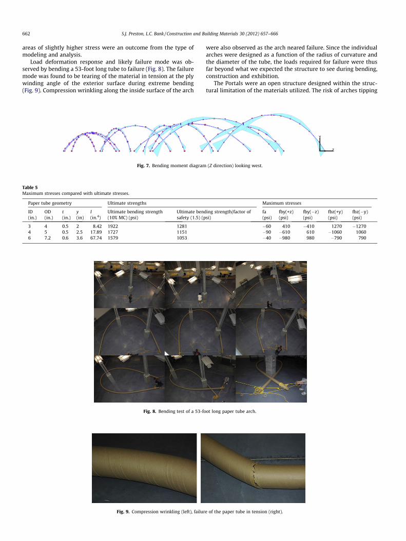
Load deformation response and likely failure mode was ob-served by bending a 53-foot long tube to failure (Fig. 8). The failuremode was found to be tearing of the material in tension at the plywinding angle of the exterior surface during extreme bending(Fig. 9). Compression wrinkling along the inside surface of the arch
Table 5Maximum stresses compared with ultimate stresses.
Paper tube geometry Ultimate strengths
ID(in.)
OD(in.)
t(in.)
y(in)
I(in.4)
Ultimate bending strength(10% MC) (psi)
Ultimate bendsafety (1.5) (p
3 4 0.5 2 8.42 1922 12814 5 0.5 2.5 17.89 1727 11516 7.2 0.6 3.6 67.74 1579 1053
Fig. 8. Bending test of a 53-fo
Fig. 9. Compression wrinkling (left), failur
Fig. 7. Bending moment diagram
were also observed as the arch neared failure. Since the individualarches were designed as a function of the radius of curvature andthe diameter of the tube, the loads required for failure were thusfar beyond what we expected the structure to see during bending,construction and exhibition.
The Portals were an open structure designed within the struc-tural limitation of the materials utilized. The risk of arches tipping
Maximum stresses
ing strength/factor ofsi)
fa(psi)
fby(+z)(psi)
fby(�z)(psi)
fbz(+y)(psi)
fbz(�y)(psi)
�60 410 �410 1270 �1270�90 �610 610 �1060 1060�40 �980 980 �790 790
ot long paper tube arch.
e of the paper tube in tension (right).
(Z direction) looking west.
663S.J. Preston, L.C. Bank / Construction and Building Materials 30 (2012) 657–666
over during installation was identified and minimized during theconstruction process by stabilizing each tube with ropes, andimmediately backfilling the foundation holes prior to the structurebeing fully connected. Additional precautions were taken to deter-mine if persons hanging from the structure would cause damage orfailure to individual arches and the structure throughout the con-struction process and exhibition. Individual load cases with pointloads acting as such forces were analyzed, and resulted in stressesmuch lower that those calculated from the dominant wind loadcases.
Fig. 11. Students constructing tube-to-tube connections.
5. Constructing the Portals
Planning and construction of the Portals was assisted by ninefreshman students who collaborated on the project in conjunctionwith an Introduction to Engineering course. They participatedthroughout the entire spring 2006 semester, with special focuson sustainability, preparation for construction, and actual buildingof the project.
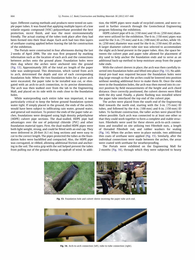
The paper tubes for the project were manufactured during thelast week of March 2006 in Hartsville, SC by Sonoco. They werecut to a length of 53 feet (16.15 m) in order to fit into a standardsemi-truck trailer, and were given a slight pre-bend (camber) toinitiate bending. To create the pre-bend, straight tubes werestacked atop two large support boxes which caused the tubes toarch under their own weight. The pre-bend took place after theadhesive binding the paper tube plies was dry, but before it fullycured. The paper tubes left Hartsville with a moisture content of12%, and arrived in Madison, WI with a moisture content around10% – a value estimated based on travel time and the rate of dissi-pation. To prevent further loss of moisture, the ends of the tubes,where a majority of the moisture is transferred, were sealed withmultiple coats of low-VOC polyurethane upon arrival. Large pedes-tal-like supports were constructed to hold the paper tubes, and toprovide a means for allowing them to creep into their desiredshape over a period of 3 weeks (Fig. 10). The tubes were supportedat four points which were incrementally raised every few days un-til each tube reached its proper curvature. Over the course of thebending process, the shape of the tubes was checked and con-firmed by measurements taken to determine the height of eacharch at various lengths along their chords. Towards the end ofthe bending process, additional force was applied to ends of the ar-ches because the self-weight of the tubes themselves was not suf-ficient to form the correct curvature through creep of the materialalone.
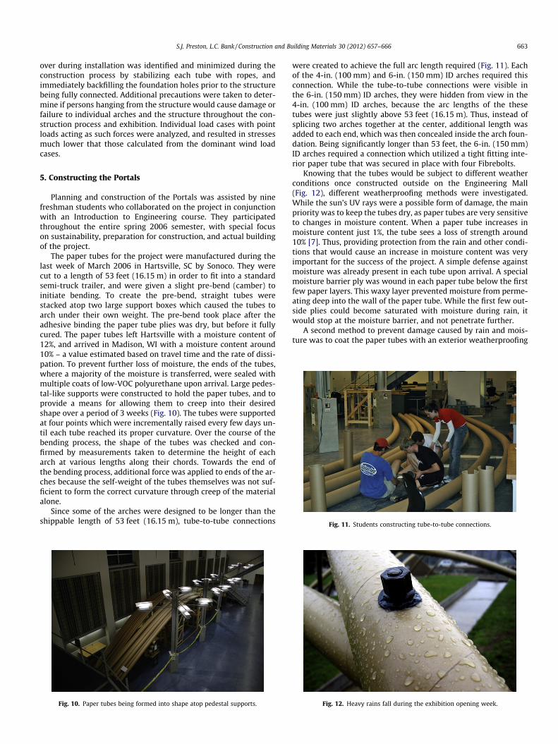
Since some of the arches were designed to be longer than theshippable length of 53 feet (16.15 m), tube-to-tube connections
Fig. 10. Paper tubes being formed into shape atop pedestal supports.
were created to achieve the full arc length required (Fig. 11). Eachof the 4-in. (100 mm) and 6-in. (150 mm) ID arches required thisconnection. While the tube-to-tube connections were visible inthe 6-in. (150 mm) ID arches, they were hidden from view in the4-in. (100 mm) ID arches, because the arc lengths of the thesetubes were just slightly above 53 feet (16.15 m). Thus, instead ofsplicing two arches together at the center, additional length wasadded to each end, which was then concealed inside the arch foun-dation. Being significantly longer than 53 feet, the 6-in. (150 mm)ID arches required a connection which utilized a tight fitting inte-rior paper tube that was secured in place with four Fibrebolts.
Knowing that the tubes would be subject to different weatherconditions once constructed outside on the Engineering Mall(Fig. 12), different weatherproofing methods were investigated.While the sun’s UV rays were a possible form of damage, the mainpriority was to keep the tubes dry, as paper tubes are very sensitiveto changes in moisture content. When a paper tube increases inmoisture content just 1%, the tube sees a loss of strength around10% [7]. Thus, providing protection from the rain and other condi-tions that would cause an increase in moisture content was veryimportant for the success of the project. A simple defense againstmoisture was already present in each tube upon arrival. A specialmoisture barrier ply was wound in each paper tube below the firstfew paper layers. This waxy layer prevented moisture from perme-ating deep into the wall of the paper tube. While the first few out-side plies could become saturated with moisture during rain, itwould stop at the moisture barrier, and not penetrate further.
A second method to prevent damage caused by rain and mois-ture was to coat the paper tubes with an exterior weatherproofing
Fig. 12. Heavy rains fall during the exhibition opening week.
S.J. Preston, L.C. Bank / Construction and Building Materials 30 (2012) 657–666664
layer. Different coating methods and products were tested on sam-ple paper tubes. It was found that applying multiple layers of a lowvolatile organic compound (VOC) polyurethane provided the bestprotection, nicest finish, and was the most environmentallyfriendly. The actual coating of the tubes took place after they hadbeen formed into their final shape. Each arch had two thin layersof urethane coating applied before leaving the lab for constructionof the exhibition.
The Portals were constructed in four afternoons during the last2 weeks of April 2006. The site was first prepared by markinginformation such as the location of each arch and the connectionsbetween arches onto the ground plane. Foundation holes werethen dug where the arches were anchored into the ground(Fig. 13). Approximately 20% of the total arc length of the papertube was underground. This dimension, which varied from archto arch, determined the depth and size of each correspondingfoundation hole. When the two foundation holes for a given archwere excavated, the paper tube to be installed was cut, or elon-gated with an arch-to-arch connection, to its precise dimensions.The arch was then walked over from the lab to the EngineeringMall, and placed on its side with its ends close to the foundationholes.
While waterproofing each entire tube was important, it wasparticularly critical to keep the below ground foundation systemwater tight. If simply placed in the ground, the ends of the archeswould have been subject to infiltrating rain water, ground water,and general soil moisture. To protect the ends of the paper tube ar-ches, foundations were designed using high density polyethylene(HDPE) culvert pipe sections. The dual-walled, HDPE pipe hadadvantages over the use of polyvinyl chloride (PVC) and otherfoundation material types. First, the dual-walled HDPE pipes wereboth light weight, strong, and could be fitted with an end cap. Theywere delivered in 20-foot (6.1 m) long sections and were easy tocut to the correct length. The pipes protected the tubes as the foun-dation holes were backfilled and compacted. Also, the HDPE pipewas corrugated, or ribbed, allowing additional friction and anchor-ing in the soil. The extra grip with the soil helped prevent the tubesfrom pulling out of the ground during an updraft of wind. In addi-
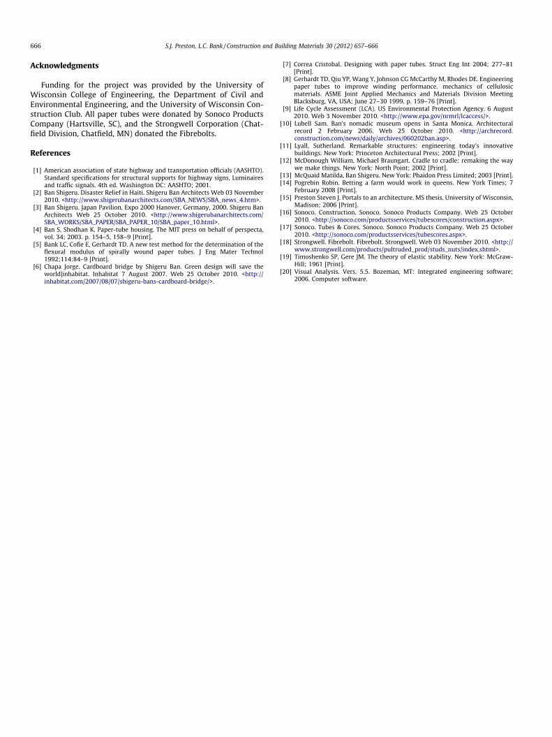
Fig. 13. Foundation hole and culvert sleev
Fig. 14. Arch-to-arch connection (left)
tion, the HDPE pipes were made of recycled content, and were re-used in further research through the Geotechnical Engineeringprogram following the exhibition.
HDPE culvert pipe of 6-in. (150 mm) and 10-in. (250 mm) diam-eter were utilized for the exhibition. The 6-in. (150 mm) pipes wasused for the 3-in. (75 mm) and 4-in. (100 mm) ID arches, while 10-in. (250 mm) diameter was used for the 6-in. (150 mm) ID arches.A larger diameter culvert tube size was selected to accommodatethe slight arch bend present in the paper tubes. Also, the space be-tween the culvert pipe and paper tube allowed for placement ofdry sand to help anchor the foundation ends and to serve as anadditional back-up method to keep moisture away from the papertube ends.
With the culvert sleeves in place, the arch was then carefully in-serted into foundation holes and lifted into place (Fig. 13). No addi-tional pre-load was required because the foundation holes weredug large enough so that the arches could be lowered into positionwithout needing additional force to make them fit. Once the endswere in the foundation holes, the arch was then moved into its cor-rect position by field measurements of the height and arch chorddistance. Once correctly positioned, the culvert sleeves were filledwith the dry sand. Finally, a plastic flashing was installed wherethe paper tube interfaced the top end of the culvert pipe.
The arches were placed from the south end of the EngineeringMall towards the north end, starting with the 3-in. (75 mm) IDtubes, and followed by the 4-in. (100 mm) and 6-in. (150 mm) IDtubes. To facilitate construction, the taller arches were placed firstwhere possible. Each arch was connected to at least one other sothat they could work together to form a complete and stable struc-ture. Fibrebolts were used for these eleven arch-to-arch connec-tions and installed on site utilizing two Fibrebolt nuts, a lengthof threaded Fibrebolt rod, and rubber washers for sealing(Fig. 14). When the arches were in-place outside, two additionalthin coats of urethane were applied (Fig. 15). Similarly, after theindividual connections were made between the arches, the areaswere coated with urethane for weatherproofing.
The Portals were exhibited on the Engineering Mall for2 months (Fig. 16), through which they were subjected to heavy
e receiving the paper tube arch end.
, tube-to-tube connection (right).
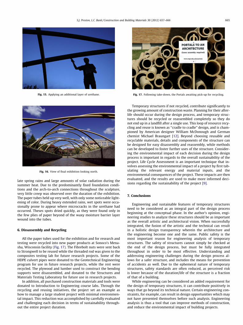
Fig. 15. Applying an additional layer of urethane.
Fig. 16. View of final exhibition looking north.
Fig. 17. Following take-down, the Portals awaiting pick-up for recycling.
665S.J. Preston, L.C. Bank / Construction and Building Materials 30 (2012) 657–666
late spring rains and large amounts of solar radiation during thesummer heat. Due to the predominantly fixed foundation condi-tions and the arch-to-arch connections throughout the sculpture,very little creep was observed over the duration of the exhibition.The paper tubes held up very well, with only some noticeable light-ening of color. During heavy extended rains, wet spots were occa-sionally prone to appear where microcracks in the urethane hadoccurred. Theses spots dried quickly, as they were found only inthe few plies of paper beyond of the waxy moisture barrier layerwound into the tubes.
6. Dissassembly and Recycling
All the paper tubes used for the exhibition and for research andtesting were recycled into new paper products at Sonoco’s Mena-sha, Wisconsin facility (Fig. 17). The Fibrebolt nuts were sent backto Strongwell to be reused while the threaded rod was given to thecomposites testing lab for future research projects. Some of theHDPE culvert pipes were donated to the Geotechnical Engineeringprogram for use in future research projects, while the rest wererecycled. The plywood and lumber used to construct the bendingsupports were disassembled, and donated to the Structures andMaterials Testing Laboratory for future use in research projects.
In addition, all purchased construction materials and tools weredonated to Introduction to Engineering course labs. Through therecycling and reusing initiatives, the project set an example ashow to manage a large student project with minimal environmen-tal impact. This reduction was accomplished by carefully evaluatedand challenging each decision in terms of sustainability through-out the entire project duration.
Temporary structures if not recycled, contribute significantly tothe growing amount of construction waste. Planning for their after-life should occur during the design process, and temporary struc-tures should be recycled or reassembled completely so they donot end up in a landfill after a single use. This loop of resource recy-cling and reuse is known as ‘‘cradle to cradle’’ design, and is cham-pioned by American designer William McDonough and Germanchemist Michael Braungart [12]. Beyond choosing reusable andrecyclable materials, details and components of the structure canbe designed for easy disassembly and reassembly, while methodscan be developed to foster further uses of the structure. Consider-ing the environmental impact of each decision during the designprocess is important in regards to the overall sustainability of theproject. Life Cycle Assessment is an important technique that in-volves assessing the environmental impact of a project by first tab-ulating the relevant energy and material inputs, and theenvironmental consequences of the project. These impacts are thenevaluated, and the results are used to make more informed deci-sions regarding the sustainability of the project [9].
7. Conclusions
Engineering and sustainable features of temporary structuresneed to be considered as an integral part of the design processbeginning at the conceptual phase. In the author’s opinion, engi-neering studies to analyze these structures should be as importantas the overall artistic and architectural vision. When successfullyintegrated, the fusion of the artistic and the technical can resultin a holistic design transparency wherein the architecture andthe engineering become one and the same. Public safety is themost important reason for engineering analysis of temporarystructures. The safety of structures cannot simply be checked atthe end of the design process, but must be fully integratedthroughout in order to be most effective. Understanding andaddressing engineering challenges during the design process al-lows for a safer structure, and includes the means for preventionof accidents as well. Due to the ephemeral nature of temporarystructures, safety standards are often reduced, as perceived riskis lower because of the duration/life of the structure is a fractionof that of a building.
While engineering can be considered an added requirement forthe design of temporary structures, it can contribute positively inways that go beyond its technical nature. Certain engineering con-straints, for example, can result in design opportunities which maynot have presented themselves before such analysis. Engineeringanalysis is thus a tool that can improve methods of construction,and reduce the environmental impact of building projects.
S.J. Preston, L.C. Bank / Construction and Building Materials 30 (2012) 657–666666
Acknowledgments
Funding for the project was provided by the University ofWisconsin College of Engineering, the Department of Civil andEnvironmental Engineering, and the University of Wisconsin Con-struction Club. All paper tubes were donated by Sonoco ProductsCompany (Hartsville, SC), and the Strongwell Corporation (Chat-field Division, Chatfield, MN) donated the Fibrebolts.
References
[1] American association of state highway and transportation officials (AASHTO).Standard specifications for structural supports for highway signs, Luminairesand traffic signals. 4th ed. Washington DC: AASHTO; 2001.
[2] Ban Shigeru. Disaster Relief in Haiti. Shigeru Ban Architects Web 03 November2010. <http://www.shigerubanarchitects.com/SBA_NEWS/SBA_news_4.htm>.
[3] Ban Shigeru. Japan Pavilion, Expo 2000 Hanover, Germany, 2000. Shigeru BanArchitects Web 25 October 2010. <http://www.shigerubanarchitects.com/SBA_WORKS/SBA_PAPER/SBA_PAPER_10/SBA_paper_10.html>.
[4] Ban S, Shodhan K. Paper-tube housing. The MIT press on behalf of perspecta,vol. 34; 2003. p. 154–5, 158–9 [Print].
[5] Bank LC, Cofie E, Gerhardt TD. A new test method for the determination of theflexural modulus of spirally wound paper tubes. J Eng Mater Technol1992;114:84–9 [Print].
[6] Chapa Jorge. Cardboard bridge by Shigeru Ban. Green design will save theworld|inhabitat. Inhabitat 7 August 2007. Web 25 October 2010. <http://inhabitat.com/2007/08/07/shigeru-bans-cardboard-bridge/>.
[7] Correa Cristobal. Designing with paper tubes. Struct Eng Int 2004; 277–81[Print].
[8] Gerhardt TD, Qiu YP, Wang Y, Johnson CG McCarthy M, Rhodes DE. Engineeringpaper tubes to improve winding performance. mechanics of cellulosicmaterials. ASME Joint Applied Mechanics and Materials Division MeetingBlacksburg, VA, USA; June 27–30 1999. p. 159–76 [Print].
[9] Life Cycle Assessment (LCA). US Environmental Protection Agency. 6 August2010. Web 3 November 2010. <http://www.epa.gov/nrmrl/lcaccess/>.
[10] Lubell Sam. Ban’s nomadic museum opens in Santa Monica. Architecturalrecord 2 February 2006. Web 25 October 2010. <http://archrecord.construction.com/news/daily/archives/060202ban.asp>.
[11] Lyall, Sutherland. Remarkable structures: engineering today’s innovativebuildings. New York: Princeton Architectural Press; 2002 [Print].
[12] McDonough William, Michael Braungart. Cradle to cradle: remaking the waywe make things. New York: North Point; 2002 [Print].
[13] McQuaid Matilda, Ban Shigeru. New York: Phaidon Press Limited; 2003 [Print].[14] Pogrebin Robin. Betting a farm would work in queens. New York Times; 7
February 2008 [Print].[15] Preston Steven J. Portals to an architecture. MS thesis. University of Wisconsin,
Madison; 2006 [Print].[16] Sonoco. Construction. Sonoco. Sonoco Products Company. Web 25 October
2010. <http://sonoco.com/productsservices/tubescores/construction.aspx>.[17] Sonoco. Tubes & Cores. Sonoco. Sonoco Products Company. Web 25 October
2010. <http://sonoco.com/productsservices/tubescores.aspx>.[18] Strongwell. Fibrebolt. Fibrebolt. Strongwell. Web 03 November 2010. <http://
www.strongwell.com/products/pultruded_prod/studs_nuts/index.shtml>.[19] Timoshenko SP, Gere JM. The theory of elastic stability. New York: McGraw-
Hill; 1961 [Print].[20] Visual Analysis. Vers. 5.5. Bozeman, MT: Integrated engineering software;
2006. Computer software.