design of a hybrid powered autonomous omni-directional vehicle of florida.pdf · design of a hybrid...
TRANSCRIPT

CIMAR OmniGator, AUVSI Intelligent Ground Vehicle Competition 2009
Design of a Hybrid Powered Autonomous Omni-DirectionalVehicle
Faculty Advisor: Carl Crane
Center for Intelligent Machines and Robotics
University of Florida, Gainesville, Florida352-392-0832

CIMAR OmniGator, AUVSI Intelligent Ground Vehicle Competition 2009 1
Design of a Hybrid Powered Autonomous Omni-DirectionalVehicle
Faculty Advisor: Carl Crane
Center for Intelligent Machines and Robotics
University of Florida, Gainesville, Florida352-392-0832
1. Introduction and Motivation
This report describes the design process and implementation utilized to realize the OmniGator, a three wheeled
omni-directional autonomous ground vehicle.
The Center for Intelligent Machines and Robotics (CIMAR) at the University of Florida has worked in
autonomous ground vehicles since the early 1990s. The lab’s autonomous vehicle architecture has evolved in that
time to include an active role in development and implementation of the JAUS architecture and was well refined
through participation in the three DARPA Ground Vehicle Challenges.
The size and speed capability of the OmniGator vehicle are tailored to allow competition in the Association for
Unmanned Vehicle System International’s (AUVSI’s) Intelligent Ground Vehicle Competition (IGVC). Most
other design considerations were chosen to allow the vehicle to serve as a development platform for future work
in the CIMAR lab.
CIMAR participated in the IGVC from 2002-2004. The experience gained in these competitions lead to a design
effort to develop a vehicle platform capable of addressing the challenges presented in the competitions. The
DARPA Challenges intervened in the development process and the OmniGator is the delayed result of this effort.
2. Design Problem
The design problem is to develop an autonomous ground vehicle that is suitable for competition in the IGVC and
useful for future research in autonomous ground vehicles at CIMAR. Waypoint traversal and lane following are
required behaviors in the IGVC. The challenges presented in the IGVC involve complex obstacles including
switchbacks and center islands, dead ends, traps, and potholes. The lab requires an open architecture with
hardware support that allows experimental development of ground vehicle autonomy.
3. Design Solution
3.1 Vehicle Mobility
Many conventional wheeled type vehicles have fixed drive wheels and change the direction of the vehicle by
orienting the steering wheels. The fixed configuration of the drive wheel constraints the mobility of the vehicle to
one as it typically follows Ackerman steering. The omni-directional vehicle platform presented in this paper has
three steerable drive wheels allowing the vehicle to maneuver in any direction instantaneously. The steerable
CIMAR OmniGator, AUVSI Intelligent Ground Vehicle Competition 2009 2
wheel mechanism used in this platform is considered as having non-holonomic mobility [7] as it requires a finite
amount of time before the steering mechanism can reorient the wheel to the next projected curve. Some special
wheel designs such as Mecanum wheels have been introduced [5] to tackle this problem by adding rollers on the
wheels. However the rolling mechanism often increases power loss due to conflicts among other actuators [8]
and are hard to build for bigger applications, thus we have chosen steerable wheel mechanism for the omni-
directional mobility.
3.2 Problem Solution
An omni-directional vehicle configuration was selected as the best mobility platform to address the challenges
expected in the IGVC. Power resources were designed to support the mobility scheme and autonomy sensor and
computational requirements. Sensor selection and computation resource selection was based on DARPA
Challenge vehicle development experience. The resulting system architecture is detailed with consideration of the
power system, drive system, and control system.
The power system consists of a modified off the shelf generator-IC engine pair coupled with lead acid batteries.
The generator-IC engine pair has been repackaged into the vehicle chassis. The generator produces alternating
current that is rectified and conditioned to supply a DC buss. This buss is backed up by lead acid batteries that
have approximately 1 KW/hr of storage. The DC buss provides power to the drive motors, steering motors,
cooling system, and control system.
The drive system consists of three drive wheels. The drive wheels are of a custom hub driven type and were
fabricated for this application. They are propelled by a frameless brushless dc motor that drives the wheel rim via
an epicyclic gear train. The drive motors are cooled by a closed coolant loop cooling system that includes a
radiator mounted on the vehicle chassis. The drive wheels are mounted on a spindle that is actuated by a steering
motor, allowing a minimum of 360 degrees of steering angle for each wheel. The steering motors are sourced
from Animatics and include a dedicated controller and amplifier. The steering/drive train is mounted on a sprung
swing arm to the vehicle’s chassis.
The control system is composed of a hardware control component and an Autonomy component. Two COTS
Micro-ATX motherboards and an embedded microcontroller are utilized to implement the control system. The
motherboards host a quad core and dual core processor and are used to run the higher level hardware control and
the autonomy. The embedded micro-controller manages the drive motors and hardware system control. The
autonomous control of the vehicle is implemented utilizing the JAUS 3.3 standard. The architecture is a
derivative of past CIMAR work utilized in the DARPA Grand and Urban Challenges.
CIMAR OmniGator, AUVSI Intelligent Ground Vehicle Competition 2009 3
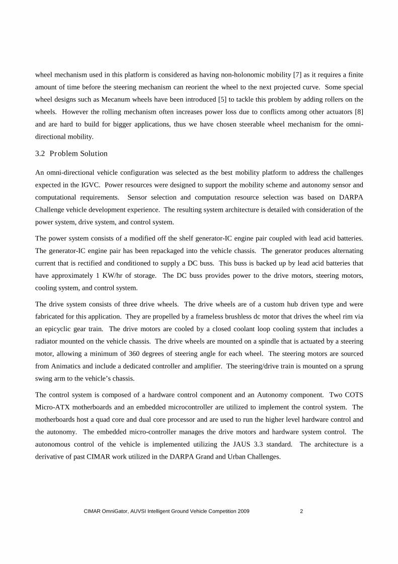
4. Hardware Platform
The vehicle’s hardware subsystems are illustrated in
figure 1. System Components include:
Outer Cover: protects compute resource
Inner Cover: Mounting surface for compute resources
Nodding LADAR: Obstacle and Terrain detection
Chassis: Enclosure and structural
“Omni” Bumper: Structural integrity
Steering Motor: Steers drive wheel
Drive wheel: Drive motor, tire, and gear train
Power system: Generator, batteries, and powerconditioning/conversion.
4.1 Drive
CIMAR undertook the design and development of a drive
wheel for omni-directional use. Fulmer [3] successfully
demonstrated the performance of a hub drive wheel for
the omni-directional vehicle in his paper. The hub drive
wheel developed consists of a brushless motor embedded
in the hub of a wheel with a two stage epicyclic gear train.
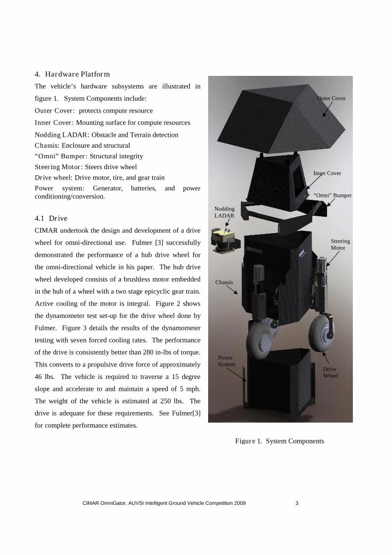
Active cooling of the motor is integral. Figure 2 shows
the dynamometer test set-up for the drive wheel done by
Fulmer. Figure 3 details the results of the dynamometer
testing with seven forced cooling rates. The performance
of the drive is consistently better than 280 in-lbs of torque.
This converts to a propulsive drive force of approximately
46 lbs. The vehicle is required to traverse a 15 degree
slope and accelerate to and maintain a speed of 5 mph.
The weight of the vehicle is estimated at 250 lbs. The
drive is adequate for these requirements. See Fulmer[3]
for complete performance estimates.
Outer Cover
Inner Cover
NoddingLADAR
“Omni” Bumper
SteeringMotor
DriveWheel
PowerSystem
Chassis
Figure 1. System Components
CIMAR OmniGator, AUVSI Intelligent Ground Vehicle Competition 2009 4
Figure 3. Dynamometer testing results
Figure 2. Dynamometer testing of drive wheel
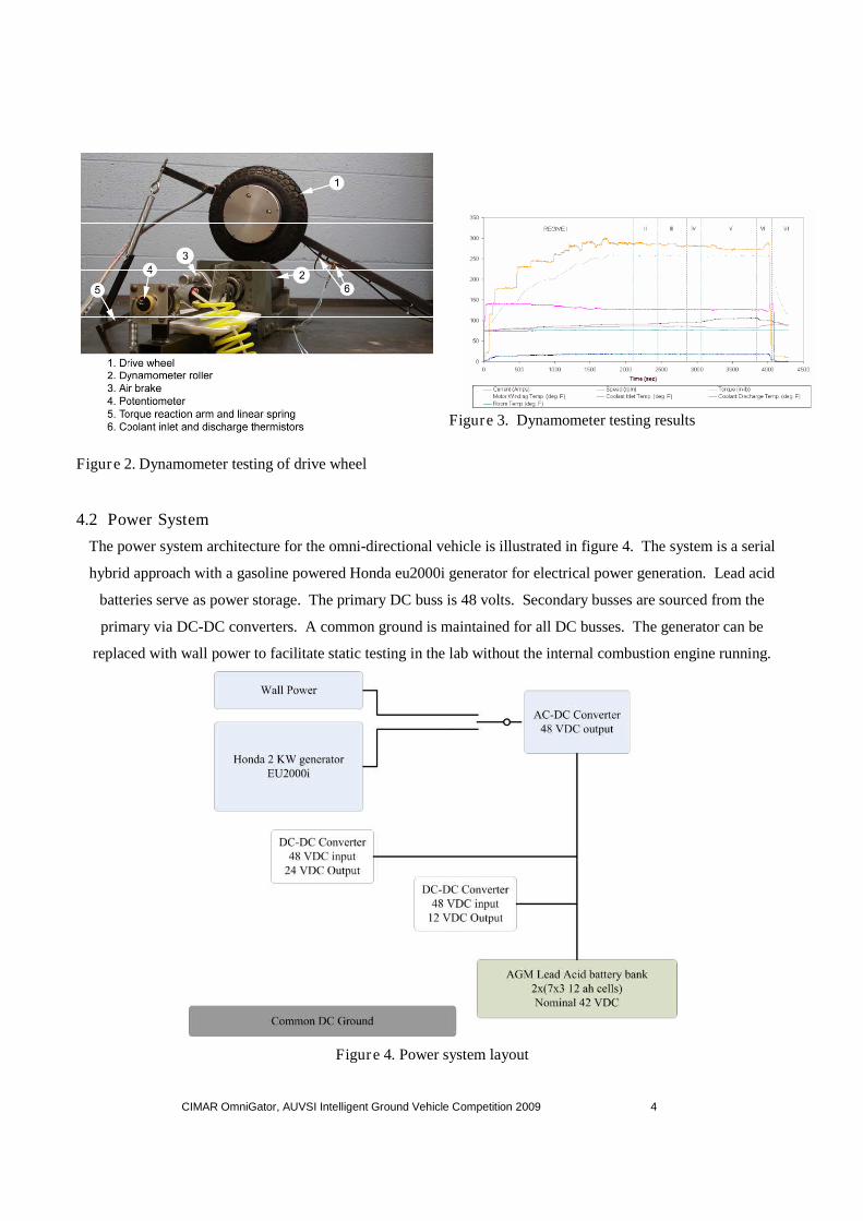
4.2 Power System
The power system architecture for the omni-directional vehicle is illustrated in figure 4. The system is a serial
hybrid approach with a gasoline powered Honda eu2000i generator for electrical power generation. Lead acid
batteries serve as power storage. The primary DC buss is 48 volts. Secondary busses are sourced from the
primary via DC-DC converters. A common ground is maintained for all DC busses. The generator can be
replaced with wall power to facilitate static testing in the lab without the internal combustion engine running.
Figure 4. Power system layout

CIMAR OmniGator, AUVSI Intelligent Ground Vehicle Competition 2009 5
4.3 Computational Resources
The omni-directional vehicle autonomy is implemented on two COTS motherboards. One motherboard supports
a quad core Intel Q9400 and the other a dual core Intel 8200 E8200. Both systems are powered by dc-dc atx
power supplies. Inter system communication is facilitated with a gigabit router.
5. Sensors
The environment of the autonomous vehicle is explored using several types of sensors. A single LADAR is
utilized for terrain classification and obstacle detection. Two cameras are used to find lines and obstacles. An
inertial measurement unit, a GPS with RTK correction, and wheel odometry are utilized for localization. A data
base called a Knowledge Store is implemented to augment situational awareness.
5.1 Localization
Localization of the autonomous vehicle is critical for our implementation of the Smart Sensor concept and the
reactive planner. The architecture requires that the sensor data be placed in a common reference frame for fusion.
We use the global frame for this purpose. Several sensors are utilized to estimate the current position and
orientation of the vehicle in the global frame. A MicroStrain 3DM-GX1 Inertial Measurement Unit (IMU) uses
an internal microprocessor to filter raw acceleration data into gyro-stabilized roll, pitch and yaw angles
dynamically accurate from 0.5° to 2° up to a tested 30Hz. This heading feedback comes with almost negligible
design impact due to the very low current draw, large supply voltage range, small enclosure construction, built-in
magnetic field compensation and RS-232 interface. To compliment the IMU, a Novatel Propak V3 is used to
acquire high precision GPS information. The Novatel unit is equipped with an RTK subscription capable of
producing global coordinates with 10cm accuracy at 20Hz. When high precision mode is not available, CDGPS
can provide 60cm accuracy – still good enough to properly locate the desired IGVC waypoint goals with the IMU
and wheel odometry. To maximize the GPS’s ability, the antenna was mounted on the very top of the robot –
limiting the amount of avoidable service interruptions (as high precision mode can take as long as twenty minutes
to reacquire). Together, these sensors provide a healthy location that enables the system components to work
intelligently placing objects in the environment more accurately.
5.2 Obstacle Detection
The CIMAR architecture implements reactive autonomy. This requires characterization of the environment local
to the vehicle. Detection of objects and classification of drivable areas are needed.
5.2.1 LADAR
The decision to include a laser range finder as part of the perception element was based on CIMAR’s many years
of experience developing autonomous vehicles. The accuracy and range of the Ladar lends itself to be an
excellent sensor for mapping the geometry of the surroundings. Since a Ladar only detects a two dimensional
cross section of space, the decision was made to create an actuated assembly that fanned the Ladar up and down

CIMAR OmniGator, AUVSI Intelligent Ground Vehicle Competition 2009 6
to capture range data in a broader three dimensional manner. This feature is critical for generating a realistic
image of obstacles as well as for determining the slope of the ground plane. Using a fixed Ladar configuration
would make detection of smooth sloping areas such as hillsides or bridges likely to be indistinguishable from
obstacles; the actuated configuration allows for these cases to be correctly classified as traversable regions.
A Sick LMS-291S05 laser range finder is mounted to the front of the vehicle with an actuator to continuously
adjust the pitch angle of the sensor. The purpose of using a ladar for mapping the vehicle environment is twofold:
obstacle detection and terrain traversability estimation. Obstacle detection is possible by extracting objects from
the surrounding ground plane point data while terrain traversability is evaluated by applying a heuristic method to
the slope and curvature of the terrain. Figure 5 shows the configuration of the sensor.
Figure 5. Ladar mounting configuration
The process of recreating the environment from the Ladar data involves first transforming the polar data to the
vehicle’s reference frame and then transforming these points to the global reference frame. The advantage of
storing and processing the time persistent data in the global reference frame is that the point data transformation is
only required once whereas keeping the data in the vehicle reference frame would require transforming old data
points as the vehicle moves and rotates. The data is stored as z-heights in a regular grid structure as opposed to an
irregular network so the points must be snapped to the nearest grid point before being stored. Since the data is
kept persistent over time, new data must be merged with this older data. A weighting factor based on age is used
so that older data has less confidence than newer data. If two points are merged that are close (i.e agreement
-90° < θ < 0°
Tiles
TraversabilityGrid Zone
Cells withvertices whichhave not beenassigned valuesare marked asunknown in theTraversabilityGrid.
All other cells aregiventraversabilityvalues based onslope, curvature,and elevation.
Figure 6. LADAR local fusion scheme

CIMAR OmniGator, AUVSI Intelligent Ground Vehicle Competition 2009 7
between old and new data), their weighting factor becomes higher. Figure 6 below illustrates the usage of
addable and removable tiles that store the point data as well as the local region that will be processed shown in
yellow.
A 30 m by 30 m region of the point data is selected and processed at each time step in order to evaluate
traversability and obstacle boundaries. This region of the laser range data is processed and a traversability grid is
formed. The traversability grid is a 121 by 121 element grid that is mapped to this region, yielding a 0.25 meter
resolution. Each entry in the traversability grid is scalar value that represents that area’s traversability based on
smoothness, slope, and elevation. This general value can be interpreted by the planning element based on the
vehicle type, that is, a region which should be avoided by one vehicle type might be safely covered by a larger
vehicle. This architecture permits reactive path planning within a 30m by 30m zone around the robot. Sending
the latest traversability grid at a rate of 10-20 Hz provides ample reaction time for a robot limited to 5 mph.
Finally, the objects that have been extracted from the ground plane based on their height above the surrounding
ground space is vectorized into a polygon and stored in the knowledge store as an obstacle.
5.2.2 Vision
The Line Finding Sensor is a vision based component which extracts line information from the local environment.
For the OMNIGATOR, we use two mvBlueFox 120aC cameras which perform the roles of finding lines as well
as obstacles. The extraction of lines is performed by using Hough transform. This is implemented using openCV
libraries.
BlueFox cameras have a capture rate of 100Hz, which provides a lot of scope for fast image processing. Also it is
USB 1.1 compatible. The driver software together with the FPGA reduce the PC load to a minimum during
preprocessing. The automatic gain control and exposure control of the BlueFox is also advantageous. The Tamron
lens chosen for the OMNIGATOR, has a variable focal length and can be used as both telephoto and wide angle
lens.
Detection of painted demarcations is accomplished by considering multiple environment cues which include
intensity, color, shape and orientation. These points of interest are searched for and linear dominant elements are
reported. The input image which is a three channel image is reconstructed into a single channel image and the
Canny algorithm is applied to it in order to detect the dominant edges. The Canny algorithm computes first
derivatives in x and y, which are then combined into four directional derivatives, where each of the maxima are
assembled into edges.
The Probabilistic Hough Transform is applied to the binary image, which is a slight variant of the Standard Hough
Transform. The Standard Hough Transform calculates the ρ and θ value of all the lines present in the frame,
where ρ and θ are the distance and angle respectively, of the line from the origin (0, 0). In our case the starting

CIMAR OmniGator, AUVSI Intelligent Ground Vehicle Competition 2009 8
position was the top right of the frame, which indicates a negative value of ρ meant the line was on the right half
of the frame. The Progressive Probabilistic Hough Transform is a variation as it accumulates only a fraction of
the points in the accumulator plane. This results in line segments with starting and ending points instead of an
infinitely long line with the given slope. This was chosen over the Standard Hough transform as the first
derivative of the set is more accurate than the ones derived by Standard Hough Transform.
For the line finding algorithm, we set an initial slope value and then perform a constant comparison with the
previous slope to see that there is no major deviation from the previous slope, thus following the same line though
it may have slight changes in slope as in the cases of curves. Once these points are extracted, the information is
sent to the Knowledge Store. The points are packed in a particular order to indicate that one side of the line is
traversable while the other is not.
Obstacle detection with the cameras has been reduced to a polygon recognition and reporting one. The obstacle in
the path is found by detecting the contour. This is implemented using openCV libraries. The binary image with
the edge pixels is classified into positive and negative regions. Depending on the intensity, the area is classified
as either a contour or a hole. The contour is the approximated into an approximate polygon. This is done by taking
the extreme ends of the contour and drawing a line between them. The point which is farthest from this line is
taken as the third point and so on. The iteration stops when the distance between the point and the line is lesser
than a specified value. Also while finding the polygons, noise may interfere with the data capture, so we assign
another condition that the area of the contour detected must be greater than a particular value (to indicate that
there is a polygon).
The points are found in a random order which is packed into a predefined clockwise order and sent to the
Knowledge Store.
5.2.3 Knowledge Store
The Knowledge Store component functions as a repository of vectorized data and information for any system
components. The Knowledge Store is designed on top of a Postgresql 8.3 database with Postgis1.3 spacial
extensions. Both were chosen for their wide usage in industry and are open source. The Postgis library of
predefined geometric functions and types was chosen to facilitate rapid integration with the overall system. The
Knowledge Store allows any number of client components to create, query, and delete instances of vectorized
objects in the database. Once the component receives and parses a message by using dynamic cues set in the
structure of the message, a SQL query string is built using definitions that are predefined within the system. The
query is then sent to the database and depending on what type information was in the message; the Knowledge
Store compiles the desired data from the database return or queries the database again depending on the results.
Vector objects stored in the database can have any number of predefined properties. These properties can be
merged into sets that describe an object. For example, a cone on the field would hold a geometry that describes

CIMAR OmniGator, AUVSI Intelligent Ground Vehicle Competition 2009
its shape as classified by sensors, a time stamp of when it was last classified, a traversability value assigned by the
client, which component classified it and so on. Three basic geometric types are supported: points, lines, and
polygons. Messaging functionality is built off of the AS
any JAUS compatible system.
6. Control
6.1 Low Level Control
As an omni-directional mechanism, three hub drive BLDC motors
are attached to an L-shaped bracket.
connected to the steering servo motor with a 48:1 gear head.
7 shows the physical arrangement of the mechanisms.
In order to control the vehicle platform, certain inputs have to be
converted to a power to drive the actuators.
JAUS architecture, the primitive driver (PD) provides the method of
interpreting plans to actuator command. PD requires low level or
hardware level control system. Figure
designed to interface with actuation systems.
A SmartMotor SM3440D from Animatics is used for the steering
equipped with individual embedded motor controller,
through RS-232 serial communication.
steering angle of the omni-directional wheel.
directional motion, abnormal forces will be applied
to the mechanism and that can potentially damage
or destroy it. To prevent such a catastrophic event
from happening, every time the device is turned on
the SmartMotor must be initialized prior to
operation. This initialization process includes
homing and alignment. An optical sensor
mounted on one side of the gear head block looking
down to the wheel bracket. A reflective tape is
placed on top of the bracket which enables the
sensor to detect the light emitted from its
and find the home.
CIMAR OmniGator, AUVSI Intelligent Ground Vehicle Competition 2009
its shape as classified by sensors, a time stamp of when it was last classified, a traversability value assigned by the
client, which component classified it and so on. Three basic geometric types are supported: points, lines, and
polygons. Messaging functionality is built off of the AS-4 standard. This allows the knowledge store to run on
directional mechanism, three hub drive BLDC motors
shaped bracket. Each wheel bracket is
servo motor with a 48:1 gear head. Figure
shows the physical arrangement of the mechanisms.
In order to control the vehicle platform, certain inputs have to be
converted to a power to drive the actuators. In the hierarchy of the
river (PD) provides the method of
ting plans to actuator command. PD requires low level or
Figure 8 shows the architecture
designed to interface with actuation systems.
A SmartMotor SM3440D from Animatics is used for the steering actuator. It is a complete servo system
equipped with individual embedded motor controller, amplifier, and an encoder. Each SmartMotor is commanded
232 serial communication. Physical alignment of the drive wheel is very important in controlling the
directional wheel. If any of the wheels are not correctly aligned towards the omni
forces will be applied
an potentially damage
To prevent such a catastrophic event
very time the device is turned on
must be initialized prior to
. This initialization process includes
An optical sensor switch is
mounted on one side of the gear head block looking
reflective tape is
placed on top of the bracket which enables the
detect the light emitted from its source
Figure 7.
Figure 2. Lowlevel control
9
its shape as classified by sensors, a time stamp of when it was last classified, a traversability value assigned by the
client, which component classified it and so on. Three basic geometric types are supported: points, lines, and
4 standard. This allows the knowledge store to run on
t is a complete servo system
and an encoder. Each SmartMotor is commanded
is very important in controlling the
wheels are not correctly aligned towards the omni-
Figure 7. Drive Configuration
Lowlevel control

CIMAR OmniGator, AUVSI Intelligent Ground Vehicle Competition 2009
Controlling the three wheel motor requires different techniques
BE40A8 BLDC motor driver from Advance Motion is used to power the motor. This motor driver converts
analog reference input to switching currents for the brushless motor.
the motor feedback control system.
computing power (up to 16MIPS at 16MHz
per revolution (CPR) attached to the motor shaft.
its embedded timer/counter. A discrete PID control algorithm is implemented in the microcontroller to
compensate the errors with newly updated encoder counts.
Where GoalRPM is desired velocity of the motor and CurrentRPM is the latest
sampling time. The sampling time in this case is set to 8ms, a sampling rate of 125 Hz. With this feedback system,
the discrete-time PID control law is shown as f
Where KP, KI and KD are the controller gains of proportional, integral and derivative terms respectively.
shows simplified diagram of the PID control system developed for the omni
Adjusting the gains used for the PID
motors with unknown characteristics.
motion, tuning of the PID motor controllers were focused
three motors are shown in Figure 1
controller.
CIMAR OmniGator, AUVSI Intelligent Ground Vehicle Competition 2009
Controlling the three wheel motor requires different techniques as it lacks both motor amplifier and controller.
BE40A8 BLDC motor driver from Advance Motion is used to power the motor. This motor driver converts
analog reference input to switching currents for the brushless motor. An embedded controller is used to complete
the motor feedback control system. An ATmega128 provides an economical and reliable solut
p to 16MIPS at 16MHz [1]). The wheel motor contains an optical encoder with 1000 counts
per revolution (CPR) attached to the motor shaft. Each pulse out from the encoder is
A discrete PID control algorithm is implemented in the microcontroller to
compensate the errors with newly updated encoder counts. The error obtained here can be expressed as
CurrentRPMGoalRPME (1)
Where GoalRPM is desired velocity of the motor and CurrentRPM is the latest encoder
The sampling time in this case is set to 8ms, a sampling rate of 125 Hz. With this feedback system,
ntrol law is shown as follows:
dt
EKtEKEKOutput DIPPID
(2)
are the controller gains of proportional, integral and derivative terms respectively.
shows simplified diagram of the PID control system developed for the omni-directional wheel motor.
Figure 9. Control system block diagram
Adjusting the gains used for the PID controller often becomes trial and error especially when trying
motors with unknown characteristics. Since the nature of the omni-directional mobility requires
motion, tuning of the PID motor controllers were focused on ensuring paralleled motion. The step
10. This result shows the performance of the newly implemented PID motor
10
as it lacks both motor amplifier and controller. A
BE40A8 BLDC motor driver from Advance Motion is used to power the motor. This motor driver converts
An embedded controller is used to complete
and reliable solution with enough
The wheel motor contains an optical encoder with 1000 counts
is fed back to the controller by
A discrete PID control algorithm is implemented in the microcontroller to
The error obtained here can be expressed as
encoder count measured during a
The sampling time in this case is set to 8ms, a sampling rate of 125 Hz. With this feedback system,
are the controller gains of proportional, integral and derivative terms respectively. Figure 9
directional wheel motor.
and error especially when trying to control
directional mobility requires synchronous
motion. The step responses of all
This result shows the performance of the newly implemented PID motor

CIMAR OmniGator, AUVSI Intelligent Ground Vehicle Competition 2009 11
Figure 10. Step response
6.2 Autonomy
The autonomy deployed on this omni directional ground vehicle is derived from the CIMAR architecture that was
developed over the course of the DARPA Ground Vehicle Challenges. The architecture implemented
traversability grids in the second Grand Challenge[2], and multiple behavior modes were implemented in the
Urban Challenge. The development of the architecture is ongoing. The current work focuses on improving
situational awareness through utilization of a knowledge store.
The architecture is implemented in a JAUS 3.3 compliant manner. JAUS defines a component as a collection of
software that performs a defined task. JAUS specifies a group of messages that allow components to
communicate. The standard leaves room for custom messages and experimental components. Some of the
architecture is experimental.
The Smart Sensor Concept developed for the Second Challenge takes raw data from the sensor level and converts
it into a format that is fusable with other sensor data, whether the sensor is of the same type or not[2][6]. The
traversability grid provided the means for this fusion to happen. Tested heuristics were utilized to fuse the data to
allow planning based on multiple sensor input with varying time and space resolutions. The addition of a
knowledge store required modification of the Smart Sensor output. We have maintained the traversability grid
and the appropriate representation of the reactive environment in which we plan in. We have the Smart Sensors
extract terrain data and represent it as a traversability grid. Obstacle data is reduced to vector representation and
stored in the Knowledge Store. This data is fused with the traversability data in a process call the Arbiter.
The fused result is then used in a receding horizon planner based on an A* search [4] combined with a receding
horizon control strategy to generate motions for the OmniGator. A goal state is determined according to the
Motor Control Response
0.0 0.5 1.0 1.5 2.0 2.5 3.0 3.5 4.0 4.5 5.0
Time (sec)
-40
-20
0
20
40
60
80
100
120
140
160
180S
peed
(RP
M)
RPM_A RPM_B RPM_C Input_A Input_BInput_C

CIMAR OmniGator, AUVSI Intelligent Ground Vehicle Competition 2009 12
operating state of the vehicle, either considering a list of waypoints to visit or corridor center estimations coming
from visual sensors. The A* algorithm expands and evaluates nodes which represent potential future states of the
vehicle in an attempt to reach this goal state. These future positions are estimated using a kinematic vehicle model
of the platform, which allows for translation in any direction. The vehicle model uses a unique, prospective
steering command associated with each potential state to calculate a position in the vehicle frame of reference.
These future states are then evaluated based on a number of different factors, including the value of the cell of the
traversability grid within which they fall, as well as their distance to the vehicle’s goal state. The evaluation of
each node is broken down into two parts and takes the form:
(݂ )݊ = ݃( )݊ + ℎ( )݊ (3)
where f(n) is the total cost of a particular node, g(n) is the known cost to get to that node, and h(n) is a heuristic
estimate of the cost to get from that node to the goal state of the vehicle. According to the A* method, the
evaluated nodes are placed in a queue where the least costly node is always first in line to be expanded. This
provides for optimality in terms of path cost. When a search node reaches the desired goal state, the algorithm
traces back the sequence of connected nodes to the first state change and uses the steering command associated
with this search node as part of the next control input to implement. This heuristic algorithm was selected for its
reactive planning capabilities. Objects present in desired travel direction are represented as areas with high
traversal costs in the traversability grid. These high costs will lead to the search algorithm expanding nodes that
avoid these areas and seek out lower cost paths.
The omni-directional vehicle’s kinematics are theatrically unrestrained in the plane (3 degrees of freedom). As
mentioned in section 2, the steering and wheel velocities cannot be controlled instantaneously, so the vehicle has
slightly non-holonomic behavior. A ray based kinematic model is utilized as the kinematic model for omni-
directional motion at the reactive planning stage, and the low level control is scheduled to compensate for the
non-holonomic behavior by retarding linear velocity in favor of correct heading.
The vehicle is expected to complete two primary behaviors: waypoint following and corridor following. In
waypoint following, the vehicle is given a list of waypoints in Latitude and Longitude. The vehicle is then
expected to navigate from point to point, avoiding obstacles. In corridor following, the vehicle is put in a corridor
defined by lines on the terrain, and expected to follow the corridor avoiding obstacles until the corridor ends.
Both of these navigational behaviors can be implemented by driving the optimization scheme of the receding
horizon planner. A desired path is imposed on the traversability grid that the Arbiter produces, leading to the
desired path being found by the planner provided no environmental factors (from sensors) restrict the plan.
Figure 11 illustrates the system diagram. The perception elements consist of the LADAR and vision smart
sensors and the GPOS component. The LADAR component utilizes the input from a LADAR sensor and the
GPOS data to define the traversability of the terrain local to the vehicle. It also detects obstacles and commits

CIMAR OmniGator, AUVSI Intelligent Ground Vehicle Competition 2009 13
them to the knowledge store component. The vision component extracts line objects and obstacles from the field
of view of two cameras. This information is vectorized and stored in the knowledge store. The GPOS component
produces a current estimate of the vehicle’s global position and pose.
The subsystem commander establishes which navigational behavior is active and monitors system health. The
corridor driver queries the knowledge store for line data to define a corridor. It establishes a series of goals for
any instant in time based on the line data. These goals are sent to the high level planner which directs the local
path planner. The waypoint driver takes an a priori list of waypoints and sends them to the high level planner in a
similar manner.
7. Team Contributions
The team is composed of numerous Mechanical and Aerospace students at the University of Florida. Both
undergrad and graduate students have participated. The initial omni-directional vehicle design was begun in
2002. The most significant contribution at that time was the design and fabrication of the hub driven drive
wheels. Chris Fulmer was the principle contributor to this development.
The next significant work was performed in 2006. The vehicle configuration was changed from four wheel to
three wheel. Previously fabricated drive wheel components were assembled. Previously designed suspension
Figure 11. Autonomy Diagram
CIMAR OmniGator, AUVSI Intelligent Ground Vehicle Competition 2009 14
components were modified for the new configuration. The chassis was fabricated. Steve Velat and Gregory
Garcia contributed to this effort.
The current effort was begun in the late Fall of 2008. This stage includes the completion of the hardware, leading
to an operational OmniGator. A large group of students have participated in this stage.
The software has undergone continuous development since CIMAR’s first participation in the IGVC.
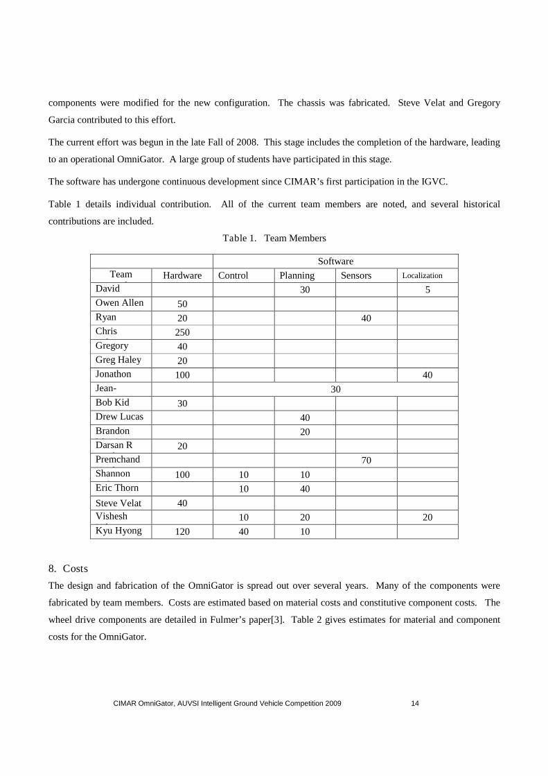
Table 1 details individual contribution. All of the current team members are noted, and several historical
contributions are included.
Table 1. Team Members
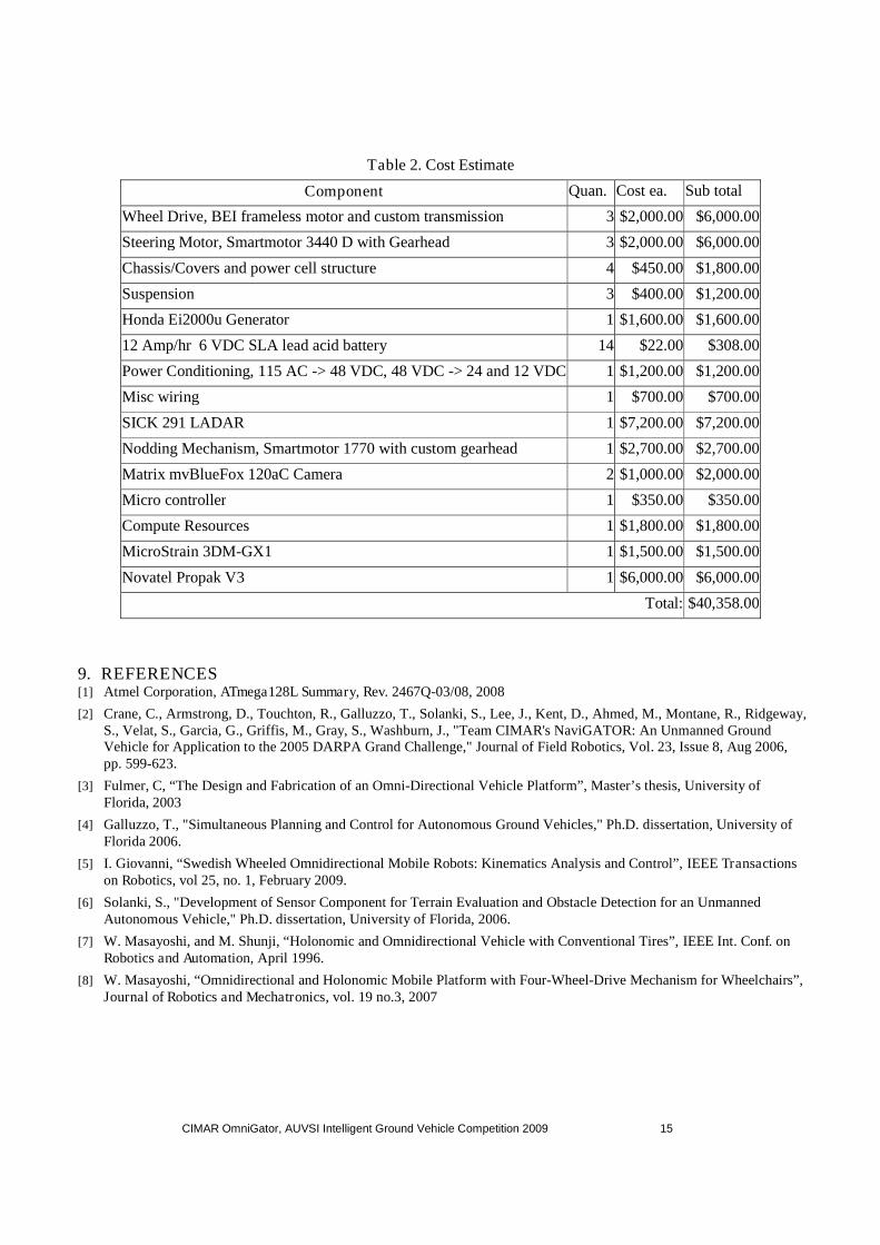
8. Costs
The design and fabrication of the OmniGator is spread out over several years. Many of the components were
fabricated by team members. Costs are estimated based on material costs and constitutive component costs. The
wheel drive components are detailed in Fulmer’s paper[3]. Table 2 gives estimates for material and component
costs for the OmniGator.
Software
TeamMember
Hardware Control Planning Sensors Localization
DavidArmstrong
30 5
Owen Allen 50
RyanChilton
20 40
ChrisFulmer
250
GregoryGarcia
40
Greg Haley 20
JonathonJeske
100 40
Jean-Francois A.
30
Bob Kid 30
Drew Lucas 40
BrandonMerritt
20
Darsan RPatel
20
PremchandKrishna
70
ShannonRidgeway
100 10 10
Eric Thorn 10 40
Steve Velat 40
VisheshVikas
10 20 20
Kyu HyongYou
120 40 10
CIMAR OmniGator, AUVSI Intelligent Ground Vehicle Competition 2009 15
Table 2. Cost Estimate
Component Quan. Cost ea. Sub total
Wheel Drive, BEI frameless motor and custom transmission 3 $2,000.00 $6,000.00
Steering Motor, Smartmotor 3440 D with Gearhead 3 $2,000.00 $6,000.00
Chassis/Covers and power cell structure 4 $450.00 $1,800.00
Suspension 3 $400.00 $1,200.00
Honda Ei2000u Generator 1 $1,600.00 $1,600.00
12 Amp/hr 6 VDC SLA lead acid battery 14 $22.00 $308.00
Power Conditioning, 115 AC -> 48 VDC, 48 VDC -> 24 and 12 VDC 1 $1,200.00 $1,200.00
Misc wiring 1 $700.00 $700.00
SICK 291 LADAR 1 $7,200.00 $7,200.00
Nodding Mechanism, Smartmotor 1770 with custom gearhead 1 $2,700.00 $2,700.00
Matrix mvBlueFox 120aC Camera 2 $1,000.00 $2,000.00
Micro controller 1 $350.00 $350.00
Compute Resources 1 $1,800.00 $1,800.00
MicroStrain 3DM-GX1 1 $1,500.00 $1,500.00
Novatel Propak V3 1 $6,000.00 $6,000.00
Total: $40,358.00
9. REFERENCES[1] Atmel Corporation, ATmega128L Summary, Rev. 2467Q-03/08, 2008
[2] Crane, C., Armstrong, D., Touchton, R., Galluzzo, T., Solanki, S., Lee, J., Kent, D., Ahmed, M., Montane, R., Ridgeway,S., Velat, S., Garcia, G., Griffis, M., Gray, S., Washburn, J., "Team CIMAR's NaviGATOR: An Unmanned GroundVehicle for Application to the 2005 DARPA Grand Challenge," Journal of Field Robotics, Vol. 23, Issue 8, Aug 2006,pp. 599-623.
[3] Fulmer, C, “The Design and Fabrication of an Omni-Directional Vehicle Platform”, Master’s thesis, University ofFlorida, 2003
[4] Galluzzo, T., "Simultaneous Planning and Control for Autonomous Ground Vehicles," Ph.D. dissertation, University ofFlorida 2006.
[5] I. Giovanni, “Swedish Wheeled Omnidirectional Mobile Robots: Kinematics Analysis and Control”, IEEE Transactionson Robotics, vol 25, no. 1, February 2009.
[6] Solanki, S., "Development of Sensor Component for Terrain Evaluation and Obstacle Detection for an UnmannedAutonomous Vehicle," Ph.D. dissertation, University of Florida, 2006.
[7] W. Masayoshi, and M. Shunji, “Holonomic and Omnidirectional Vehicle with Conventional Tires”, IEEE Int. Conf. onRobotics and Automation, April 1996.
[8] W. Masayoshi, “Omnidirectional and Holonomic Mobile Platform with Four-Wheel-Drive Mechanism for Wheelchairs”,Journal of Robotics and Mechatronics, vol. 19 no.3, 2007