design guidelines - missouri
TRANSCRIPT

DESIGN GUIDELINES

FORWARD
The Design Guidelines contained herein are not to be considered to be all-inclusive. On each project the Designer will be confronted with particular needs, requirements and design limitations particular to the individual project. These guidelines provide a basic criterion for projects designed through the Division of Facilities Management, Design and Construction. Thus these guidelines are to be considered suggestive only, and the Designer should analyze and review if the guidelines are applicable on each individual project. Projects designed through the Division of Facilities Management, Design and Construction shall be designed in accordance with the latest edition of codes and standards published by the following:
The Americans With Disabilities Act (ADAAG) International Building Code (IBC) National Electric Code (NEC) International Mechanical Code (IMC) International Plumbing Code (IPC) National Fire Protection Agency (NFPA 101) American Society of Heating Refrigerating and Air-Conditioning Engineers ASHRAE Standard 90.1 for Energy Efficient Design of New Buildings except Low-Rise Residential Buildings) American Society of Mechanical Engineers (ASME) American National Standards Institute (ANSI) American Concrete Institute (ACI) Sheet Metal and Air Conditioning Contractor's National Association (SMACNA) Boiler and Pressure Vessel Act of the State of Missouri.
The Consultant shall also include any other codes or standards which are applicable to the project but not listed above. If there are significant differences between the local codes and current International Codes, the designer shall discuss with the local authority to resolve the issues. If a resolution cannot be reached, the Division Director shall be contacted for ruling. The designer shall also adhere to the space guidelines for the Division of Facilities Management, Design and Construction. The designer must also consider the life cycle cost of each item specified in new construction projects, as well as the Missouri Domestic Products Procurement Act. The Missouri Domestic Products Procurement Act states that any manufacturers’ goods or commodities used or supplied in the performance of the construction shall be manufactured, assembled or produced in the United States, unless the specified products are not manufactured, assembled, or produced in the United States in sufficient quantities to meet the agencies’ requirements or cannot be manufactured, assembled or produced in the United States within the necessary time in sufficient quantities to meet the contract requirements, or if the obtaining the specified products manufactured, assembled or produced in the United States would increase the cost of the contract or purchase of the product more than 10%. These design guidelines have been organized in Construction Specifications Institute (CSI) divisions for clarity. They will be periodically reviewed and revised to ensure specific guidance to the professional and to communicate the special needs of the State. The State further requests that should the Designer, in the course of use of these Design Guidelines, find areas that are too restrictive or need more specific detail to assure a minimum level of quality, the Designer please submit to the Assistant Director of the Division of Facilities Management, Design and Construction any recommended modifications. For this purpose a Recommended Modification form has been provided as an appendage to these Guidelines.
Revision 04/07

CSI SPECIFICATION REFERENCE

CSI SPECIFICATION REFERENCE PAGE 1
The Design shall use the CSI Specification reference numbers shown below for each Specification. DIVISION 2 - SITE CONSTRUCTION
02060 BUILDING DEMOLITION 02070 SELECTIVE DEMOLITION 02080 UTILITY MATERIALS 02110 SITE CLEARING 02200 EARTHWORK 02260 EXCAVATION SUPPORT AND PROTECTION 02282 TERMITE CONTROL
02455 DRIVEN PILES 02456 CONCRETE-FILLED STEEL PILES 02457 PRESTRESSED CONCRETE PILES 02458 STEEL H PILES 02459 TIMBER PILES
02466 DRILLED PIERS 02510 WATER DISTRIBUTION 02511 HOT-MIX ASPHALT PAVING 02515 UNIT PAVERS 02520 PORTLAND CEMENT CONCRETE PAVING
02553 NATURAL GAS DISTRIBUTION 02554 FUEL-OIL DISTRIBUTION
02700 SEWERAGE AND DRAINAGE 02711 FOUNDATION DRAINAGE SYSTEMS
02764 PAVEMENT JOINT SEALANTS 02776 POND AND RESERVOIR LINERS
02813 LAWN SPRINKLER PIPING 02831 CHAIN LINK FENCES AND GATES 02900 LANDSCAPING
DIVISION 3 - CONCRETE
03300 CAST-IN-PLACE CONCRETE 03350 CONCRETE TOPPINGS 03355 SPECIAL CONCRETE FINISHES 03410 STRUCTURAL PRECAST CONCRETE - PLANT CAST 03450 ARCHITECTURAL PRECAST CONCRETE - PLANT CAST 03455 GLASS-FIBER REINFORCED CONCRETE - PLANT CAST 03470 TILT-UP PRECAST CONCRETE 03520 INSULATING CONCRETE DECKS
DIVISION 4 - MASONRY
04200 UNIT MASONRY 04405 DIMENSION STONE CLADDING 04410 STONE MASONRY VENEER 04815 GLASS UNIT MASONRY ASSEMBLIES 04901 CLAY MASONRY RESTORATION AND CLEANING 04902 STONE RESTORATION AND CLEANING
DIVISION 5 - METALS
05120 STRUCTURAL STEEL 05210 STEEL JOISTS 05310 STEEL DECK 05400 COLD-FORMED METAL FRAMING 05500 METAL FABRICATIONS 05510 METAL STAIRS 05521 PIPE AND TUBE RAILINGS 05530 GRATINGS 05580 SHEET METAL FABRICATIONS

CSI SPECIFICATION REFERENCE PAGE 2
05700 ORNAMENTAL METALWORK 05720 ORNAMENTAL HANDRAILS AND RAILINGS 05810 EXPANSION JOINT COVER ASSEMBLIES
DIVISION 6 - WOOD AND PLASTICS
06100 ROUGH CARPENTRY 06105 MISCELLANEOUS CARPENTRY 06130 HEAVY TIMBER CONSTRUCTION 06150 WOOD DECKING 06185 STRUCTURAL GLUED-LAMINATED TIMBER 06192 METAL-PLATE-CONNECTED WOOD TRUSSES 06200 FINISH CARPENTRY 06401 EXTERIOR ARCHITECTURAL WOODWORK 06402 INTERIOR ARCHITECTURAL WOODWORK
DIVISION 7 - THERMAL AND MOISTURE PROTECTION
07111 COMPOSITE SHEET WATERPROOFING 07112 POLYMERIC SHEET WATERPROOFING 07121 COLD FLUID-APPLIED WATERPROOFING 07122 HOT FLUID-APPLIED WATERPROOFING 07160 BITUMINOUS DAMPPROOFING 07190 WATER REPELLENTS 07210 BUILDING INSULATION 07241 EXTERIOR INSULATION AND FINISH SYSTEMS - CLASS PB 07242 EXTERIOR INSULATION AND FINISH SYSTEMS - CLASS PM 07270 FIRESTOPPING 07311 ASPHALT SHINGLES 07317 WOOD SHINGLES AND SHAKES 07411 MANUFACTURED ROOF PANELS 07412 MANUFACTURED WALL PANELS 07460 SIDING 07511 BUILT-UP ASPHALT ROOFING 07512 BUILT-UP COAL-TAR ROOFING 07531 EPDM SINGLE-PLY MEMBRANE ROOFING 07532 CSPE SINGLE-PLY MEMBRANE ROOFING 07533 THERMOPLASTIC SINGLE-PLY MEMBRANE ROOFING 07551 APP-MODIFIED BITUMINOUS MEMBRANE ROOFING 07552 SBS-MODIFIED BITUMINOUS MEMBRANE ROOFING 07570 TRAFFIC COATINGS 07620 SHEET METAL FLASHING AND TRIM 07710 MANUFACTURED ROOF SPECIALTIES 07720 ROOF ACCESSORIES 07810 PLASTIC UNIT SKYLIGHTS 07811 SPRAYED FIRE-RESISTIVE MATERIALS
07920 JOINT SEALANTS DIVISION 8 - DOORS AND WINDOWS
08110 STEEL DOORS AND FRAMES 08114 CUSTOM STEEL DOORS AND FRAMES 08211 FLUSH WOOD DOORS 08212 STILE AND RAIL WOOD DOORS 08305 ACCESS DOORS 08311 ALUMINUM SLIDING GLASS DOORS 08312 WOOD SLIDING GLASS DOORS 08314 SLIDING METAL FIRE DOORS 08331 OVERHEAD COILING DOORS 08334 OVERHEAD COILING GRILLES 08351 FOLDING DOORS 08361 SECTIONAL OVERHEAD DOORS

CSI SPECIFICATION REFERENCE PAGE 3
08410 ALUMINUM ENTRANCES AND STOREFRONTS 08450 ALL-GLASS ENTRANCES 08460 AUTOMATIC ENTRANCE DOORS 08470 REVOLVING ENTRANCE DOORS 08510 STEEL WINDOWS 08520 ALUMINUM WINDOWS 08550 WOOD WINDOWS
08630 METAL-FRAMED SKYLIGHTS 08710 DOOR HARDWARE 08800 GLAZING 08920 GLAZED ALUMINUM CURTAIN WALLS
DIVISION 9 - FINISHES
09210 GYPSUM PLASTER 09215 GYPSUM VENEER PLASTER 09220 PORTLAND CEMENT PLASTER 09255 GYPSUM BOARD ASSEMBLIES 09265 GYPSUM BOARD SHAFT-WALL ASSEMBLIES 09310 CERAMIC TILE 09385 DIMENSION STONE TILE 09400 TERRAZZO 09451 INTERIOR STONE FACING 09511 ACOUSTICAL PANEL CEILINGS 09512 ACOUSTICAL TILE CEILINGS 09546 LINEAR METAL CEILINGS 09550 WOOD FLOORING 09600 STONE PAVING AND FLOORING 09635 BRICK FLOORING 09651 RESILIENT TILE FLOORING 09652 SHEET VINYL FLOOR COVERINGS 09653 RESILIENT WALL BASE AND ACCESSORIES 09680 CARPET 09690 CARPET TILE 09800 SPECIAL COATINGS
09841 ACOUSTICAL WALL PANELS 09900 PAINTING
09950 WALL COVERINGS DIVISION 10 - SPECIALTIES
10100 VISUAL DISPLAY BOARDS 10155 TOILET COMPARTMENTS 10200 LOUVERS AND VENTS 10265 WALL SURFACE PROTECTION SYSTEMS 10270 ACCESS FLOORING 10350 FLAGPOLES 10416 DIRECTORIES AND BULLETIN BOARDS 10425 SIGNS 10436 POST AND PANEL SIGNS
10505 METAL LOCKERS 10520 FIRE-PROTECTION SPECIALTIES
10550 POSTAL SPECIALTIES 10605 WIRE MESH PARTITIONS 10651 OPERABLE PANEL PARTITIONS 10653 FIRE-RATED OPERABLE PANEL PARTITIONS 10655 ACCORDION FOLDING PARTITIONS 10750 TELEPHONE SPECIALTIES
10801 TOILET AND BATH ACCESSORIES DIVISION 11 - EQUIPMENT

CSI SPECIFICATION REFERENCE PAGE 4
11062 STAGE CURTAINS 11065 PORTABLE THEATER AND STAGE EQUIPMENT 11132 PROJECTION SCREENS 11150 PARKING CONTROL EQUIPMENT 11160 LOADING DOCK EQUIPMENT 11172 WASTE COMPACTORS 11400 FOOD SERVICE EQUIPMENT
11451 RESIDENTIAL APPLIANCES 11460 UNIT KITCHENS
DIVISION 12 - FURNISHINGS
12372 KITCHEN CASEWORK 12496 WINDOW TREATMENT HARDWARE 12511 HORIZONTAL LOUVER BLINDS 12512 VERTICAL LOUVER BLINDS 12680 FOOT GRILLES 12690 FLOOR MATS AND FRAMES 12710 FIXED AUDIENCE SEATING 12760 TELESCOPING STANDS
DIVISION 13 - SPECIAL CONSTRUCTION
13052 SAUNAS 13122 METAL BUILDING SYSTEMS
DIVISION 14 - CONVEYING SYSTEMS
14100 DUMBWAITERS 14210 ELECTRIC TRACTION ELEVATORS 14240 HYDRAULIC ELEVATORS 14310 ESCALATORS
14560 CHUTES DIVISION 15 - MECHANICAL
15050 BASIC MECHANICAL MATERIALS AND METHODS 15100 VALVES 15125 PIPE EXPANSION JOINTS 15135 METERS AND GAGES 15145 HANGERS AND SUPPORTS 15170 MOTORS 15241 MECHANICAL VIBRATION CONTROLS AND SEISMIC RESTRAINTS 15250 MECHANICAL INSULATION 15411 WATER DISTRIBUTION PIPING 15420 DRAINAGE AND VENT PIPING 15430 PLUMBING SPECIALTIES 15440 PLUMBING FIXTURES 15452 SEWAGE AND SUMP PUMPS 15453 WATER DISTRIBUTION PUMPS 15455 WATER STORAGE TANKS 15457 WATER SOFTENERS 15460 WATER HEATERS 15461 ELECTRIC WATER HEATERS 15462 FUEL-FIRED WATER HEATERS 15465 COMPRESSED-AIR EQUIPMENT 15481 COMPRESSED-AIR PIPING 15491 FUEL OIL PIPING 15496 NATURAL GAS PIPING 15501 HEATING BOILERS AND ACCESSORIES 15510 HYDRONIC PIPING 15511 RADIANT HEATING PIPING

CSI SPECIFICATION REFERENCE PAGE 5
15512 CAST-IRON BOILERS 15513 CONDENSING BOILERS 15519 ELECTRIC BOILERS 15520 STEAM AND CONDENSATE PIPING 15530 REFRIGERANT PIPING 15540 HVAC PUMPS 15545 CHEMICAL WATER TREATMENT 15575 BREECHINGS, CHIMNEYS, AND STACKS 15580 FEEDWATER EQUIPMENT 15582 STEAM CONDENSATE RETURN UNITS 15610 FURNACES 15620 FUEL-FIRED HEATERS 15625 CENTRIFUGAL WATER CHILLERS 15628 RECIPROCATING WATER CHILLERS 15640 PACKAGED COOLING TOWERS 15661 FLUID COOLERS 15663 EVAPORATIVE CONDENSERS 15671 CONDENSING UNITS 15672 AIR-COOLED CONDENSERS 15745 WATER-SOURCE HEAT PUMPS 15755 HEAT EXCHANGERS 15782 ROOFTOP UNITS 15783 COMPUTER-ROOM AIR-CONDITIONING UNITS 15784 PACKAGED TERMINAL AIR-CONDITIONING UNITS 15790 AIR COILS 15812 FIBROUS-GLASS DUCTS 15815 METAL DUCTS 15820 DUCT ACCESSORIES 15831 FAN-COIL UNITS 15832 FINNED-TUBE RADIATION 15833 RADIANT HEATING PANELS 15835 UNIT HEATERS 15840 UNIT VENTILATORS 15845 AIR TERMINALS 15850 FANS 15851 CENTRIFUGAL FANS 15852 AXIAL FANS 15853 POWER VENTILATORS 15854 CENTRAL-STATION AIR-HANDLING UNITS 15855 DIFFUSERS, REGISTERS, AND GRILLES 15861 AIR FILTERS 15970 HVAC CONTROLS 15975 CONTROL SYSTEMS EQUIPMENT 15985 SEQUENCE OF OPERATION 15990 TESTING, ADJUSTING, AND BALANCING
DIVISION 16 - ELECTRICAL
16010 BASIC ELECTRICAL REQUIREMENTS 16050 BASIC ELECTRICAL MATERIALS AND METHODS 16120 CONDUCTORS AND CABLES 16121 CONTROL/SIGNAL TRANSMISSION MEDIA 16122 UNDERCARPET CABLES 16130 RACEWAYS AND BOXES 16139 CABLE TRAYS 16140 WIRING DEVICES
16231 PACKAGED ENGINE GENERATORS 16265 CENTRAL BATTERY INVERTER
16415 TRANSFER SWITCHES 16425 SWITCHBOARDS 16450 ENCLOSED BUS ASSEMBLIES 16452 GROUNDING

CSI SPECIFICATION REFERENCE PAGE 6
16461 DRY-TYPE TRANSFORMERS (1000 V AND LESS) 16470 PANELBOARDS 16475 FUSES 16476 DISCONNECT SWITCHES AND CIRCUIT BREAKERS 16481 MOTOR CONTROLLERS 16482 MOTOR-CONTROL CENTERS 16515 INTERIOR LIGHTING 16525 EXTERIOR LIGHTING 16611 STATIC UNINTERRUPTIBLE POWER SUPPLY 16670 LIGHTNING PROTECTION 16715 PREMISES TELEPHONE WIRING 16721 FIRE ALARM SYSTEMS 16722 INTERCOMMUNICATION EQUIPMENT 16726 PUBLIC ADDRESS AND MUSIC EQUIPMENT 16727 SOUND-MASKING EQUIPMENT 16740 VOICE AND DATA SYSTEMS 16856 ELECTRIC HEATING CABLES

TABLE OF CONTENTS PAGE 1
SPECIFICATION GUIDELINES

TABLE OF CONTENTS PAGE 2
TABLE OF CONTENTS
DIVISION 2 - SITE CONSTRUCTION General Provisions Asphalt Paving Portland Cement Paving Gravel Paving Landscaping DIVISION 3 - CONCRETE Cast-In-Place Concrete DIVISION 4 - MASONRY Unit Masonry DIVISION 5 - METALS Steel Structures Steel Joists Metal Fabrications Pre-Fabricated Expansion Joint Covers DIVISION 6 - WOODS AND PLASTICS Rough Carpentry Metal-Plate-Connected Wood Trusses Finish Carpentry DIVISION 7 THERMAL AND MOISTURE PROTECTION Shingles Modified Bituminous Roofing Manufactured Roof Panels (Metal) Single Ply Roofing DIVISION 8 - DOORS AND WINDOWS Steel Doors and Frames Wood Doors Sectional Overhead Doors Aluminum Entrances and Storefronts Aluminum Windows Wood Windows Door Hardware Glazing DIVISION 9 - FINISHES Gypsum Board Assemblies Ceramic Tile

TABLE OF CONTENTS PAGE 3
Acoustical Ceilings Resilient Flooring Carpet Resinous Flooring Painting DIVISION 10 - SPECIALTIES Chalkboards and Tackboards Toilet Compartments Wall and Corner Guards Access Flooring Signage Fire Protection Specialties Demountable Partitions Operable Partitions Toilet Accessories DIVISION 11 - EQUIPMENT DIVISION 12 - FURNISHINGS Manufactured Casework Window Treatments Floor Mats Fixed Audience Seating DIVISION 13 - SPECIAL CONSTRUCTION Pre-Engineered Metal Buildings DIVISION 14 - CONVEYING SYSTEMS Electrical Traction Elevators Hydraulic Elevators DIVISION 15 - MECHANICAL General Provisions Valves Meters and Gages Motors Hangers and Supports Mechanical Insulation Plumbing Specialties Plumbing Piping Water Softeners Water Heaters Natural Gas Piping System Hydronic Piping Steam and Condensate Piping Refrigerant Piping HVAC Pumps Cast Iron Boilers Fire Tube Boilers Feedwater Equipment

TABLE OF CONTENTS PAGE 4
Steam Condensate Return Units Furnaces Condensing Units Reciprocating Chillers Water Cooled Centrifugal Chillers Factory Fabricated Cooling Towers Air Cooled Condensers Packaged Heating and Cooling Units Central Station Air Handling Units DIVISION 16 - ELECTRICAL General Provisions Basic Electrical Requirements Basic Electrical Materials and Methods Raceways Wires and Cables Control/Signal Cables Cabinets, Boxes and Fittings Wiring Devices Circuit and Motor Disconnects Supporting Devices Electrical Identification Switchboards Grounding Transformers Panelboards Fuses Motor Controllers Automatic Transfer Switches Interior Lighting Exterior Lighting Packaged Engine Generator Systems Fire Alarm Systems Telephone Systems

TABLE OF CONTENTS PAGE 5
CODES AND STANDARDS
ARI - Air Conditioning and Refrigeration Institute AMCA - Air Moving and Contracting Association AABC - American Air Balance Council AAMA - American Architectural Manufacturers Association ACI - American Concrete Institute ADA - Americans with Disabilities Act AFPA - American Forest and Paper Association AGA - American Gas Association ALSC - American Lumber Standards Committee ANSI - American National Standards Institute APA - American Plywood Association ASHRAE - American Society of Heating, Refrigerating and Air Conditioning Engineers ASME - American Society of Mechanical Engineers ASTM - American Standards and Testing Methods AWS - American Welders Association BIA - Brick Institute of America BHMA - Builders Hardware Manufacturers Association BOCA - Building Officials and Code Administrators DHI - Door and Hardware Institute FTI - Facing Tile Institute NAHB - National Association of Home Builders NCMA - National Concrete Masonry Association NEC - National Electrical Code

TABLE OF CONTENTS PAGE 6
NEMA - National Electric Manufacturers Association NFPA - National Fire Protection Agency NWWDA - National Wood Window and Door Association SMACNA - Sheet Metal and Air Conditioning Contractors National Association SDI - Steel Door Institute UL - Underwriters Laboratories, Inc.

DESIGN GUIDELINES PAGE 1
DIVISION 2 - SITE CONSTRUCTION GENERAL PROVISIONS A. Parking Lots 1. All parking lots shall comply with ADA. 2. Slopes shall be designed at a minimum of 1% and a maximum of 4%. Slopes
greater than 4% must be approved by the owner. 3. Accessible parking shall be provided for both employees and public. They may
be provided in each lot or in a different location if such location provides greater accessibility. Parking layout shall comply with 4.1.2 (S) of ADAAG Standards. “Van Accessible” parking is required.
4. Paint colors shall be white for general lot striping, yellow for no parking areas,
and blue for disabled access spaces and areas. 5. Parking spaces shall typically be 9’ in width. No compact car spaces shall be
permitted, unless approved by owner. 6. Asphalt surfaced lots - Refer to asphalt paving section. 7. Concrete surfaced lots - Refer to Portland Cement Paving section. B. Sidewalks and Ramps 1. Sidewalks shall be designed with positive drainage away from walks. Drainage
of surface water shall not cross sidewalks. 2. Sidewalks and ramps shall be designed to prevent water entering a building.
Overflow areas shall be provided if necessary. 3. Lateral slope for sidewalks shall be no less than 1% and no more than 2%. 4. Materials a. The preferred material for sidewalks, ramps, and other paved, exterior
walking surfaces is concrete. No material shall be used for a walking surface that may become slippery when wet.
b. Concrete: Minimum strength 3500 psi Air 6% Reinforcing Minimum 6x6/10x10 (6x6 - w 1.4 x w
1.4) welded wire fabric. (1) Base for concrete shall be a minimum of 4” of MoDOT Type I (Sec
304) aggregate for base. (2) Joints (a) All joints shall be shown on the plans. (b) Joints may be either tooled or sawn. If the joints are sawn,
they shall be sawn within 12 hours of the placement of the concrete.

DESIGN GUIDELINES PAGE 2
(c) Joints shall be sealed with traffic grade, non-asphalt, non-
extruding sealant. (3) A medium broom finish shall be applied perpendicular to the traffic
flow. All brooming directions shall be shown on the drawings and described in the specifications.
(4) Use of calcium chloride shall not be permitted. (5) Testing (a) The concrete shall be tested for strength, air entrainment,
temperature, and slump. The specifications shall indicate allowable limits for each.
(b) The contractor will retain the services of a testing firm.
The contractor shall be responsible for scheduling the tests. The contractor shall be required to notify the owner’s representative a minimum of 48 hours prior to all placement of concrete.
(c) Concrete shall be tested at the minimum rate of one test
for the first 5 cy. placed each day, and one test for each additional 50 cy. placed. The concrete may be tested more often at the discretion of the owner’s representative.
(d) The specifications shall make it clear to the contractor that
quality control is the responsibility of the contractor. The above testing in no way relieves the contractor of the responsibility to comply with the specifications.
5. Guardrails and Handrails a. This standard shall apply to all exterior guardrails and handrails that are
not a significant part of a building’s architecture. b. All railings shall comply with the latest version of the Americans with
Disabilities Act. c. Materials (1) All guardrails and handrails shall be primarily constructed of steel
pipe. The infill for guardrails shall be constructed of vertical balusters only. No panels shall be used for the infill.
(2) Prior to installation, the rails shall be hot dip galvanized. Any
repairs or alterations shall receive a galvanizing coating prior to being painted.
d. All railings shall be of welded construction. FOUNDATIONS A. Site Evaluation 1. Soil borings

DESIGN GUIDELINES PAGE 3
a. The geotechnical characteristics of the site is to be determined during the
initial project design phase for “Maintenance and Repair” projects, where rock may possibly be encountered, and for all new construction projects, where excavation will occur. Sufficient soil borings are to be taken to accurately profile the top of rock line in all areas being considered for excavation, including footings and under slab utilities. The top of rock profile is to be provided to the Project Manager with the initial design phase submittal.
b. As a minimum, there is to be one soil boring for each 2,000 square feet of
building footprint, with no less than four borings for any one building. c. The results of all soil borings and soil classifications shall be included for
reference in the technical specifications. B. Excavation and Backfill 1. Rock excavation a. A unit price shall be required for each kind of rock excavation that shall be
used to adjust the base bid, for either more or less rock excavation than the amount included in the base bid.
2. Spread and pad footings a. The bearing soil shall be compacted to a minimum of 95% of maximum
density at optimum moisture content (+ 2%), standard proctor (ASTM D 698). Excavation to undisturbed soil is not considered adequate.
b. Immediately prior to installation of reinforcing steel and placement of
concrete, the soil shall be inspected by the soil engineer. The inspecting agency will be retained and scheduled by the contractor.
3. Backfill a. Backfill around foundations shall be installed in no more than 12” lifts.
Specific situations or soils may require smaller lifts. b. Using a standard proctor at optimum moisture content (+ 2%), all backfill
shall be mechanically compacted to a minimum of 88% and a maximum of 92% of maximum density under landscaped areas and a minimum of 95% of maximum density under other areas.
c. The backfill shall be inspected and tested at the discretion of the owner’s
representative and soils engineer. The contractor shall retain the services of an engineering inspection and testing firm. The contractor shall be responsible for coordinating and scheduling the inspections.

DESIGN GUIDELINES PAGE 4
C. Concrete 1. All concrete used in footings, foundations, or slabs shall have a minimum
strength of 3,500 psi. 2. Calcium chloride shall not be used in any concrete. 3. Masonry units shall not be used for foundation walls below grade. D. Reinforcement 1. Reinforcing steel and accessories shall not be placed in contact with soil.
Reinforcing steel shall not extend to the surface of the concrete. Chairs and other accessories shall be plastic or epoxy coated at the point of contact with the surface of the concrete.
E. Drainage Systems 1. A footing/foundation positive drainage system shall be installed on all buildings
with usable space below grade. a. Place perforated Schedule 40 PVC drain pipe at the base of the
foundation wall around the perimeter of the building, connected to a storm sewer.
b. Embed the pipe in 12” of 1” clean rock on all sides of the pipe. c. Install an 8” thick vertical layer of 1” clean rock on the exterior of the
foundation wall from the footing to rough grade. 2. Piping a. All pipe used in foundation drainage systems shall be a minimum of
Schedule 40. Use of flexible corrugated drain tile is not allowed. b. Cleanouts shall be installed downstream of each 90 degree elbow, within
12” of the elbow. On straight runs of pipe, cleanouts shall not be located more than 100’ apart. All cleanouts shall be supplied with brass plugs.
c. All drainage piping shall be connected to storm sewer piping, not sanitary
sewer. F. Slabs on Grade (Interior) 1. All slabs on grade shall rest on a minimum of 4” clean compacted crush rock or
gravel. Provide a 6-mil polyethylene vapor barrier beneath concrete slab. 2. The structural fill or natural (undisturbed) bearing soil under slabs on grade shall
be compacted to a minimum of 95% of maximum dry density at optimum moisture content and to a depth of at least one foot, or provide compaction as recommended in the soils report. Excavation to undisturbed soil without compaction testing is not considered adequate.

DESIGN GUIDELINES PAGE 5
3. Joints a. Joint spacing and joint detail shall be shown on the drawings. b. Expansion joints shall be required with a maximum spacing between
joints of 30 feet. Expansion joints shall have dowel bars and shall allow load transfer. Non-extruding expansion joint material shall be used.
c. Control joints shall be cut as soon as the concrete can be walked on
without damage to the finish (soft cut). Control joints shall be cut a minimum of 1 1/2” deep or 25% of the slab thickness, whichever is greater.
d. Slab flatness and levelness shall be within 1/8” in 10’. ASTM E1155 shall
not be used to specify flatness and levelness unless the particular use requires a high level of accuracy. Areas that have floor drains shall not be required to meet the levelness tests, but shall have positive slope to the floor drain. The amount and direction of slope for floor drains shall be indicated on the drawings.
G. Underground Utility Markers 1. All underground utilities shall be marked with a warning tape buried 6” below
grade, and directly above the buried utility line. 2. Warning tape shall be a minimum 6” width polyethylene. If the buried utility line
is of a non-conductive material, the warning tape shall be a detectable type. A warning tape shall be in addition to any tracer wire that may be specified.
3. Warning tape shall have the appropriate marking, identifying the type of utility –
electric, telephone, water, sewer, gas, fiber optic, etc. H. Lawn (turf) sod to be used in the Capitol Complex projects, where grasses are disturbed. I. A time schedule for planting shall be provided and timed in relation to the planting
season. J. The construction contract shall state that landscape plants shall be maintained by the
contractor for a period of time. This period is to be determined by the project manager and facility manager.
K. Sites are to be designed to slope the ground away from all structures for the first 10 feet
at a minimum 5% grade outside the building line. L. Remove water from site as quickly as feasible with a maximum surface drainage velocity
of 4 feet per second. M. Accessible parking in a location most convenient to the accessible entrance should
comply with 4.6, 4.7 and 4.8 of ADAAG. N. Curb ramps should have detectable warnings.

DESIGN GUIDELINES PAGE 6
SECTION 02511 ASPHALT PAVING SECTION 02520 PORTLAND CEMENT PAVING GRAVEL PAVING A. General Information
Pavement design is very site specific. Therefore no one standard applies to all projects. As a minimum, adequate care must be given to the following: 1. Design Period – How long do you expect the pavement to last under expected
traffic conditions with normal preventive maintenance? State projects should be designed for a minimum of fifteen (15) year expected life.
2. Traffic (ESAL) – Equivalent single axle loadings. Traffic areas vary within a
single site. Driveways and areas with heavy traffic shall be designed for the expected traffic. Loading dock areas, motorcycle parking, areas around trash docks, and fuel-dispensing areas should be concrete. Car only parking areas will require less structural capacity.
3. Subgrade Support – On all new paved areas, a soils report with CBR for use in
pavement design is required. Design of the subgrade including soil compaction, type of base required for proper drainage and expansiveness of the soil will all affect the life of the pavement.
4. Drainage – Drainage considerations in pavement design include providing a
proper base for surface pavement, drainage structures such as curb and gutter, drop inlets, and slopes of finished payment.
5. Base – The type and thickness of base courses for pavement depends totally on
the items discussed above. Aggregate stone base or asphalt base shall meet MoDOT gradation standards.
6. Surface System – Again, the type of surface pavement depends on all of the
above, particularly the Design Period and the Traffic. Asphalt or concrete surface pavement shall be designed with the standards below as a minimum requirement.
B. New Construction
In new construction, the designer has the ability to incorporate features in the pavement design that will prolong the useful life of the paved area. These include: 1. Sites shall be graded in such a manner that the base as well as the pavement
surface has drainage away from the pavement area. Don’t excavate from a dead level surface for the base and surface courses.
2. If pavement occurs at the toe of a slope, adjacent to excavated rock, in an area
always wet, or if for any other reason continued moisture is likely, provide underslab drainage tiles or other controlled drainage at the edge of the paved areas.
3. Except for accessible parking areas, pavement should have a minimum of one-
percent (1%) slope with a maximum of four percent (4%) slope. Drives should have a maximum of eight percent (8%) slope.
4. Curb and gutter with controlled storm drainage is preferred.

DESIGN GUIDELINES PAGE 7
5. Accessible parking shall be provided as per ADAAG. No area of accessible parking or accessible route from accessible parking shall exceed two percent (2%) cross-slope. All accessible parking shall have access aisles. At least one, eight (8) foot access aisle (Van Accessible) with an eight (8) foot parking space shall be provided.
C. Asphalt Pavement
All asphalt pavements shall conform to the MoDOT Specifications. All asphalt installed in two layers should have the joints staggered. Asphalt paving shall consist of one of two types: 1. Standard Pavement – Medium Duty (Cars and Light Trucks)
a. Aggregate Base Six Inch (6”) Type 1 (or as per soils report) b. Asphalt Base Two Inch (2”) Black Base as per MoDOT 301. c. Surface Paving One and One Half Inch (1 – ½”) Type BP-2 Asphalt
per MoDOT 401.
D. Concrete Pavement
All concrete shall have the following minimums: 1. Medium Duty Parking Lot Paving (Cars and Light Trucks)
a. Aggregate Base Four (4) Inch aggregate base b. Concrete Surface Five (5) Inch concrete – no reinforcing
2. Heavy Duty Paving (Roadways, Driveways, Docks, Truck or Bus)
a. Aggregate base Four (4) Inch aggregate base b. Concrete Surface Six (6) inch concrete c. Reinforcing 6 x 6 – W2.9 x W2.9 reinforcing mesh
3. Expansion and/or Contraction joints in concrete pavement should be spaced no greater than 16 foot on center. Concrete should be batched with ¾ inch aggregate and a maximum slump of 4”. Expansion joint material and dowels should be used any time a rigid pavement is placed adjacent to an existing structure. Construction joints should have epoxy coated dowel, slip joints. No keyway joints are allowed. Joints in new pavement should be filled with a semi-rigid, epoxy joint filler, or asphalt filler.
E. Gravel (Aggregate) Pavement
Gravel lots should be avoided. If necessary, provide sufficient crown for proper drainage. 1. Medium Duty Parking Lot
a. Four (4) inch Grade A or B base b. Two (2) inch rolled, Type 1 base cap
2. Heavy Duty Lot or Road
a. Six (6) inch Grade A or B base b. Three (3) inch rolled, Type 1 base cap
DESIGN GUIDELINES PAGE 8
F. Asphalt Overlays
Asphalt overlays should consist of 2 inches of BP-2 asphalt as per MoDOT specifications. All joints should be treated by either filling or by filling and covering with a heavy fabric underlayment prior to the overlay. Remove and replace any locations where the pavement has failed or where serious cracking is evident.
G. Joint Filling And Sealcoating
Pavement should never be sealcoated without first filling all open joints. 1. Seal Coating
a. Fog Seals are effective to renew old asphalt and to seal small cracks. b. Emulsion Slurry Seals are used to fill cracks and scaled areas. c. Sand Seals are used to improve skid resistance and for waterproofing.
(Sand sealing is not recommended for parking lots.)
2. Rout and/or blow out all cracks and fill prior to sealcoating.
3. If pavement has never before been sealed, require the first coat to be squeegeed. Second coat may be sprayed.
4. Seal approximately 5 to 6 years after asphalt is placed if normal traffic.
5. Seal coating is more cosmetic than preventive maintenance, but will help fill
cracks and joints to maintain watertightness. H. Replacement
Recycling existing asphalt may provide adequate base before overlaying, but many times if the pavement has completely failed, total replacement is required. If replacement is the option, determine why it failed, and correct existing problems. New construction designs as discussed should then be followed.

DESIGN GUIDELINES PAGE 9
SECTION 02900 LANDSCAPING A. GENERAL LANDSCAPING POLICY
1. The intent and extent of landscaping shall be to provide ground cover and prevent soil erosion on the project site. There will be no flower beds, special plantings, shrubs or exotic trees included in our construction projects. Trees native to the region may be planted for the purpose of soil stabilization and erosion control.
2. On new and existing sites, the client agency will be responsible for the maintenance of seeded areas and sod immediately following the verification by the Construction Administrator that the specified quantities of fertilizer and seed have been applied. Fertilizer and seed will be specified in our projects by application rate and total quantities to be applied.
3. Sod may be acceptable as an alternative on extreme slopes and areas that serve as drainage waterways where soil erosion would be inevitable.
4. The Construction Administrator is required to be on site during the fertilization and seeding operations to verify that the proper procedure, application rate, and quantities have been used.
5. Seeding is permissible only within the time periods specified. Seeding may not occur until a permanent source of water is available at the site for use by the client agency.
6. Damage to seeded or sodded areas during the project shall be repaired by the persons or firms responsible for causing such damage.
B. NEW CONSTRUCTION
On new construction, if requested by the client agency, we will allow our consultants to develop landscaping plans for future use by the agency. A portion of the C. I. project funds may be authorized and designated for the client agency to purchase and install beds, plantings, shrubs and trees not included in our construction project. However, the Division will not support or administer any future C. I. projects for that purpose. The intent is that the agencies purchase the materials and perform the work with their own forces.

DESIGN GUIDELINES PAGE 10
DIVISION 3 - CONCRETE SECTION 03300 - CAST-IN-PLACE CONCRETE A. The following codes, specifications and standards shall be followed. Where
provisions of the codes and standards conflict with the BOCA National Building Code, BOCA shall govern.
1. BOCA National Building Code. 2. ACI 301 “Specifications for Structural Concrete Buildings.” 3. ACI 318 “Building Code Requirements for Structural Concrete.” B. Quality Assurance: Employ acceptable testing laboratory to perform materials
evaluation, testing and design of concrete mixes. Testing shall comply with: 1. Sampling: ASTM C 172 2. Slump: ASTM C 143 3. Air Content: ASTM C 173 4. Compressive Strength: ASTM C 39 The specifications shall include a provision requiring that the General Contractor shall
submit his proposed methods for curing of concrete to the Designer for approval not less than 10 days prior to placement of any concrete.
C. Concrete materials shall comply with these standards: 1. Portland Cement: ASTM C 150, Type as required. 2. Aggregates: ASTM C 33 Normal Weight or ASTM C 330 Lightweight
Aggregates. 3. Water: Potable. 4. Synthetic Fiber reinforcing; ASTM C 1018 and ASTM C 1116. 5. Air-Entraining Admixture: ASTM C 260. 6. Water-Reducing admixture: ASTM C 494. 7. Membrane-Forming Curing Compound: ASTM C 309, Type I. 8. Deformed Reinforcing Bars: ASTM A 615, Grade 60. 9. Welded Wire Fabric: ASTM A 185. 10. Ready-Mix Concrete: ASTM C 94. 11. Placement in Cold Weather: ACI 306. 12. Placement in Hot Weather: ACI 305. D. Testing 1. The concrete shall be tested for strength, air entrainment, temperature, and
slump. The specifications shall indicate allowable limits for each. 2. The contractor shall retain the services of a testing firm. The contractor shall be
responsible for scheduling the tests. The contractor shall be required to notify the owner’s representative a minimum of 48 hours prior to all placement of concrete.
3. Concrete shall be tested at the minimum rate of one test for the first 5 cy. placed
each day, and one test for each additional 50 cy. placed. The concrete may be tested more often at the discretion of the owner’s representative.
DESIGN GUIDELINES PAGE 11
4. The specifications shall make it clear to the contractor that quality control is the responsibility of the contractor. The above testing in no way relieves the contractor of the responsibility to comply with the specifications.
E. Calcium chloride shall not be permitted. F. Slab flatness and levelness shall be within 1/8” in 10’. ASTM E 1155 shall not be
used to specify flatness and levelness unless the particular use requires a high level of accuracy. Areas that have floor drains shall not be required to meet the levelness tests, but shall have positive slope to the floor drain. The amount and direction of slope for floor drains shall be indicated on the drawings.
G. All concrete used in footings, foundations, or slabs shall have a minimum
strength of 3,500 PSI. H. Joint spacing and joint details shall be shown on the drawings. I. All exterior concrete shall be air-entrained and conform to requirements of ACI
301.

DESIGN GUIDELINES PAGE 12
DIVISION 4 - MASONRY SECTION 04200 - UNIT MASONRY GENERAL A. Standards 1. Brick Institute of America Technical Notes 2. National Concrete Masonry Association B. Requirements 1. Masonry Materials: a. Brick; All brick shall comply with ASTM C216 - 75. SW (Severe
Weather) and FBS (Variation in mechanical perfection and wide color range). All brick shall have a rating of “no efflorescence” when tested according to ASTM C67.
b. Concrete Masonry; All exterior exposed concrete masonry units and
mortar shall contain integral water repellent. Units shall comply with ASTM C 33 and ASTM C 90, grade N water permanence per ASTM E 514 test. Wind driven protection per ASTM E 514-74, Class E. Full wall flexural bond strength per ASTM E 72-74 all interior concrete masonry shall be grade N, Type I, moisture controlled units.
c. Glass Unit Masonry; Glass unit masonry may be double walled or solid.
Solid units shall be used in high abuse areas. d. Clay Tile Unit Masonry; Clay tile unit masonry should generally not be
used as a finish material, but for backup or patching existing construction. e. Structural Glazed Facing Tile; All units shall conform to ASTM C 126 or
the Facing Tile Institute “Select Quality Units” including the following: imperviousness, resistance to fading and crazing resistance to scratching, toxic fumes.
f. Modular Block Retaining Wall: All units shall meet requirements of ASTM
C 90-90 except compressive strength shall be a minimum of 3,000 psi. Geo-synthetic fabric reinforcing “tie-backs” in accordance with retaining wall manufacturer’s engineering design.
g. Flashings; All concealed flashing (through wall flashing) shall be
composite flexible sheet formulated from virgin polyvinyl chloride, minimum 20 mils thick.
h. Weeps; Weeps shall be constructed with 1/4” diameter cotton rope at 16”
on center or tubes at 24 “ on center. Other types of weeps may be used if manufacturer’s recommendations are followed regarding spacing and installation.

DESIGN GUIDELINES PAGE 13
i. Lintels, Shelf and Relief Angles; All angles incorporated into masonry walls shall be hot dipped galvanized and shall have stainless steel fasteners. Shelf and relief angles shall be discontinuous at expansion joints.
j. Anchors and Ties; All anchors and ties shall be galvanized steel and
adjustable type. Anchors and ties shall permit horizontal and vertical movement, but lateral restraint. Corrugated ties are not acceptable. Gauge and spacing of anchors and ties shall be determined by compressive and tensile loads imposed on the structure in question, however wire ties shall be a minimum of 9 gauge. Coping stones shall be secured with stainless steel anchors and pins.
k. Mortar; Portland cement - lime mortar only. Masonry cement is not
acceptable. High bond additive shall not be used. Mortar to meet standard of ASTM C 270.
2. Masonry Design: a. Avoid the use of special brick shapes. b. Avoid the use of parapets unless matching or modifying existing facilities. c. Avoid the design of horizontal masonry surfaces. Tops of masonry walls
should be sloped or protected with metal copings. d. Cavity walls shall be installed without mortar droppings between wythes. e. The backup for veneer construction shall be designed so that vertical
deflection does not exceed 1/720 of the clear span under total loads. f. Flashing & Weep Holes shall be installed at the following locations: 1. Continuous at the base of walls and above finish grade. 2. Window sills. 3. Above steel lintels, relief angles and shelf angles. 4. Projections, recesses and caps. 5. Tops of walls and beneath parapet copings. g. All flashing shall be lapped at least 6” and sealed with a compatible
mastic. Flashings that are not continuous shall be turned up at ends to form dams. I.E. window & door heads, window sills, etc.
h. Expansion joints shall be placed in all masonry walls as necessary for
anticipated wall movement and in accordance with the following: 1. Walls more than 50 feet in length.

DESIGN GUIDELINES PAGE 14
2. Between new and old construction. 3. Between different materials. 4. At intersecting walls. 5. At changes in wall heights. 6. At shelf or relief angles. i. Expansion joints shall be filled with sealant and backer rod. Where
possible, align joints with openings. j. Stone copings should not be installed with mortar or grout, but with
stainless steel anchors and pins. All head joints shall be filled with sealant.
k. Outside masonry corners on the interior of a building should generally be
bullnosed.

DESIGN GUIDELINES PAGE 15
DIVISION 5 - STRUCTURAL AND MISCELLANEOUS STEEL SECTION 05120 - STEEL STRUCTURES A. General 1. The specifications shall clearly state the responsibility for the design of steel
connections. The responsibility may lie with the project designer or with the steel supplier. The responsible party must seal the connection designs.
2. Testing: The contractor will retain the services of an independent testing agency
to test steel connections. Early in the design phase, the A/E shall estimate the cost of steel testing. The contractor shall be responsible for the cost of retesting any steel connections that fail any tests. The contractor shall be required to provide a minimum of 24 hours notice to the owner’s representative prior to the time testing will be needed.
B. Codes and Standards 1. BOCA National Building Code. 2. AISC “Specifications for the Design, Fabrication and Erection of Structural Steel
for Buildings.” 3. AISC “Code of Standard Practice for Steel Buildings and Bridges.” 4. AISC “Specifications for Structural Joints using ASTM A325 or A490 Bolts.” 5. AWS D1.1 “Structural Welding Code.” C. Connections 1. All connections shall develop the strength required by the reactions of the
members. Connections shall be made as detailed. Where details are not provided, connections shall be standard except as otherwise specified or noted for the particular work.
2. All beam and column connections shall be as detailed, or if not detailed, shall be
Standard A.I.S.C. framed beam connections. Shop connections may be welded. All welding shall conform to AWS D1.1. Field connections shall be welded or bolted.
3. Design documents shall indicate the type or types of construction (i.e., Type 1,
Rigid Frame, Type 2, Simple Framing, Type 3, Semi Rigid Framing) and shall include the loads and design requirements necessary for preparation of shop drawings including shears, moments and axial forces to be resisted by all members and their connections.
D. Materials 1. Structural Steel Shapes, Plates, and Bars: ASTM A 36. 2. Cold-Formed Steel Tubing: ASTM A 500, Grade B. 3. Hot-Formed Steel Tubing: ASTM A 501.

DESIGN GUIDELINES PAGE 16
4. Steel Pipe: ASTM A 53, Type E or S, Grade B; or ASTM A 501. a. Finish: Black, except where indicated to be galvanized. 5. Anchor Bolts: ASTM A 307, nonheaded type unless otherwise indicated. 6. Unfinished Threaded Fasteners: ASTM A 307, Grade A, regular low-carbon
steel bolts and nuts. a. Provide hexagonal heads and nuts for all connections. 7. High Strength Threaded Fasteners: Heavy hexagon structural bolts, heavy
hexagon nuts, and hardened washers, as follows. a. Quenched and tempered medium-carbon steel bolts, nuts, and washers,
complying with ASTM A 325.

DESIGN GUIDELINES PAGE 17
SECTION 05210 - STEEL JOISTS A. Codes and Standards to be followed: 1. BOCA National Building Code. 2. Steel Joist Institute (SJI) Standard Specifications, load tables and weight tables. 3. AWS D1.1 “Structural Welding Code”. B. Materials 1. Comply with SJI Specifications. 2. Steel Primer paint to comply with SJI Specifications.

DESIGN GUIDELINES PAGE 18
SECTION 05500 - METAL FABRICATIONS A. General 1. The specifications shall clearly state the responsibility for the metal
fabrications/miscellaneous steel. B. Codes and Standards 1. BOCA National Building Code. 2. American Institute of Steel Construction “Manual of Steel Construction” latest
edition. 3. AISC “Code of Standard Practice for Steel Buildings and Bridges”. 4. American Welding Society, AWS D1.1 “Structural Welding Code”. C. Materials 1. Structural Steel Shapes, Plates and Bars: ASTM A36. 2. Cold formed steel tubing: ASTM A500, Grade B. 3. Hot formed steel tubing: ASTM A501. 4. Steel pipe: ASTM A53, Type E or S, Grade B; or ASTM A501. D. Applications 1. Ladders: All ladders shall be constructed to meet ANSI A14.3 Code (OSHA)
Type 1 Industrial Metal Ladders. 2. Ships ladders shall be fabricated of open type construction with structural steel or
aluminum stringers, pipe handrails and open grating treads. Ladders shall have minimum 1/8” pitch; 4” channel stringers; 4” treads; pipe handrail both sides; openings swing out; openings 32” wide, 48” high; 24” ladder width, maximum.
3. Loose Steel Lintels: All loose steel lintels to be installed in exterior walls shall be
galvanized. 4. Miscellaneous Framing and Supports - Relief Angles: All miscellaneous steel
framing to be installed in exterior walls shall be galvanized. 5. Steel Railings and Handrails: All exterior steel railings and handrails shall be
galvanized.

DESIGN GUIDELINES PAGE 19
SECTION 05810 - PREFABRICATED EXPANSION JOINT COVERS 1. Prefabricated expansion joint covers for interior floor expansion joints shall be
metal with closures which allow horizontal movement - expansion and contraction - and vertical misalignment. 2. Resilient, flexible joint closures are not acceptable.

DESIGN GUIDELINES PAGE 20
DIVISION 6 - WOOD AND PLASTICS SECTION 06100 - ROUGH CARPENTRY A. Standards 1. American Forest and Paper Association 2. American Plywood Association 3. National Association of Home Builders 4. Western Wood Products Association 5. Southern Forest Products Association 6. American Lumber Standards Committee B. Materials 1. Lumber: a. All lumber shall be kiln dried and shall have a moisture content of no
more than 19%. b. Provide lumber in species, grades and sizes appropriate for intended use.
Comply with standards published by associations having jurisdiction on species type.
c. Preservative Treated Lumber shall be used at the following locations: 1. Unpainted wood that is exposed to the exterior. 2. Wood in contact with masonry or concrete. 3. Wood within 18” of grade. d. Fire-Retardant Treated Lumber may be used where required or permitted
in lieu of noncombustible materials for certain applications allowed by code.
2. Panel Products: a. Plywood: Acceptable Uses; Wall and roof sheathing, subflooring, underlayment,
backing and blocking. Provide APA performance rated panels for type, exposure, and thickness appropriate to applications.
b. Particleboard: Acceptable Uses; Underlayment, subflooring, and wall sheathing.
Provide APA performance rated panels for type, exposure and thickness appropriate to applications.

DESIGN GUIDELINES PAGE 21
c. Hardboard: Acceptable Uses; Underlayment. d. Waferboard: Use is discouraged except in special applications. e. Oriented Strand board Use is discouraged except in special applications. 3. Engineered Wood Products: a. Engineered wood products, such as prefabricated “I” beams, laminated-
veneer lumber, parallel-strand lumber glulams and composite sections for use as beams, columns, headers and joist are acceptable for use in wood frame construction provided that complete engineering information is furnished for each proposed application.
b. Prefabricated structural wood members shall conform to NDS-91. 4. Framing Connectors & Supports: a. All framing connectors and supports shall be hot dipped galvanized steel. 5. Fasteners: a. All nails, screws, bolts and nuts that are exposed to the exterior or used
to fasten treated lumber shall be hot dipped galvanized steel complying with ASTM A 153.
C. General Requirements 1. Wood Frame Construction: a. Wood frame construction is discouraged for state buildings except for
structures within state parks, additions to existing wood frame structures or structures that are so small that wood framing is the most logical choice.
b. Wood foundation systems are not acceptable for any applications. c. Anchor all bearing plates with hooked anchor bolts at a minimum of 48”
on center. d. All wood trusses or rafters shall be tied to bearing plates with hurricane/
seismic anchors. e. It is preferred that exterior walls be made up of 2 x 6 studs rather than 2 x
4 studs. f. Provide at least 3 studs at all wall corners. g. All sill plates set on masonry or concrete shall have sill sealer insulation
sandwiched between the plate and the concrete or masonry. h. Provide adequate ventilation of all attic spaces, crawl spaces, soffits, and
between roof deck and insulation placed in rafters.

DESIGN GUIDELINES PAGE 22
i. Install wood blocking within all stud walls (metal or wood) for the attachment of trims toilet accessories, toilet partitions, or any accessories to be attached to hollow walls.

DESIGN GUIDELINES PAGE 23
SECTION 06192 - METAL-PLATE-CONNECTED WOOD TRUSSES A. Standards 1. Truss Plate Institute 2. Wood Truss Council of America 3. The Metal-Plate-Connected Wood Truss Handbook B. Materials 1. Lumber: a. Provide lumber that conforms to types, sizes, and grades as required by
truss design. 2. Metal Connector Plates: a. Metal connector plates shall be hot dipped galvanized steel or stainless
steel in sizes required by the truss design. C. General Requirements 1. Shop drawings shall be required for all truss designs. 2. Prefabricated wood trusses to comply with: a. TP1-85 Design Specification for metal-plate-connected wood trusses. b. NDS-91 National Forest Products Association Specifications. 3. Trusses shall be engineered to withstand design loads within limits and under
conditions required. 4. All wood trusses shall be anchored to bearing plates with hurricane/seismic
connectors.

DESIGN GUIDELINES PAGE 24
SECTION 06200 - FINISH CARPENTRY A. Standards 1. American Hardboard Association 2. Architectural Woodwork Institute 3. Architectural Woodwork Quality Standards 4. Hardwood Plywood and Veneer Association 5. National Hardwood Lumber Association 6. Wood Molding and Millwork Producers Association B. Materials 1. Lumber: a. Moisture content of lumber shall conform to AWI standards. b. Provide lumber in species, grades and sizes appropriate for intended use.
Comply with standards published by associations having jurisdiction on species type.
c. Preservative Treated Lumber shall be used at the following locations: 1. Wood in contact with masonry or concrete. 2. Wet locations. d. Fire-Retardant Treated Lumber may be used where required or permitted
in lieu of noncombustible materials for certain applications allowed by code.
2. Panel Products: a. Plywood: Acceptable Uses; Cabinets, countertops, paneling, siding, equipment
mounting boards, blocking and backing. Provide panels for type, exposure, and thickness appropriate to applications.
b. Particleboard: Acceptable Uses; Cabinets, countertops, blocking, and backing. Provide
panels for type, exposure and thickness appropriate to applications. c. Hardboard: Acceptable Uses; Cabinets and paneling.
DESIGN GUIDELINES PAGE 25
3. Fasteners: a. Fasteners used for finish carpentry shall generally not be exposed to
view. C. General Requirements 1. Exposed Wood Construction: a. Exposed wood construction is discouraged for state buildings except for
structures within state parks, additions to existing structures which require matching existing finishes.
b. Running trim shall be made in the longest lengths as possible to
minimize the number of joints. Panels shall be furnished in the largest sizes available in order to minimize joints.
c. All trim shall be sealed or backprimed before installation. This includes
edges and joints. d. Furnish finished carpentry items assembled and finished to the greatest
extent possible in the shop.

DESIGN GUIDELINES PAGE 26
DIVISION 7 – THERMAL AND MOISTURE PROTECTION SECTION 07311 – SHINGLES SECTION 07411 – MANUFACTURED ROOF PANELS (METAL) SECTION 07526 – MODIFIED BITUMINOUS ROOF SECTION 07530 – SINGLE PLY ROOFING A. General Information
The following information is intended to help avoid common roof problems and to help determine which type of roof to select in a new construction or re-roofing project. This information is based on previous Division experience, and current trends in the roofing industry. 1. No asbestos containing materials shall be allowed. Specifically caution about
use of asbestos mastics and primers that are still available today.
2. Minimize penetrations in roofs, space penetrations no closer than 24 inches apart, extend flashings a minimum of 12 inches above any overflow or drain, use factory made penetrations if possible, do not use galvanized material for flashings. Use a termination bar and counter-flashing at parapet walls, or if the parapet is short not watertight, extend membrane over the top of the wall and attach to front face behind cap. Corner caps and allowance for expansion and contraction in metal flashings is required. Umbrellas or hoods over all pipe flashings for equipment and over pitch pockets are required. Conduit and small pipe penetrations must be made through the side of metal flashings with proper sealants.
3. Provide walkways to all rooftop equipment. Avoid interior gutter installations.
Use two-piece, cast iron, interior drains. Use pipe tubes for equipment stands. Place equipment a minimum of 24 inches above roof deck for future re-roofing.
4. For Single-Ply systems or Modified Bitumen roofs, interior roof drains and
parapet walls with scuppers, are preferable. Avoid the use of gravel guards. If structural system is flat, locate drains at mid points between columns.
5. Primary slope for new roofs should be obtained through the structural system.
Use “two-way” slope and crickets, not “four-way” or warped slopes. Minimum slope for all roofs is ¼ inch per 12 inches per BOCA Code.
6. Insulation system shall be compatible with the application and warranty specified.
Roofing manufacturer must approve the insulation system required for roofing warranty.
7. Comply with ASHRAE 90 energy requirements with no less than an average U
Value of .05 for the composite roofing system. A vapor barrier below the primary insulation is required over shower houses, swimming pools, boiler rooms, or any other area subject to high humidity conditions. A worksheet to locate critical temperatures should be utilized for vapor barrier review.
8. All full Labor and Material Warranty (weathertightness) signed by both the
installer and the manufacturer is required.
9. Sheet metal, flashings, roof composite construction, parapets, terminations, expansion joints, and penetrations shall be designed according to the 1996 NRCA Roofing and Waterproofing Manual details and specifications unless approved by Director.

DESIGN GUIDELINES PAGE 27
10. All new and re-roof projects shall be designed for UL 90 or FM 1-90 ratings and
specifications shall specify a minimum wind speed warranty of 72 MPH.
11. No roofing or re-roofing project is to begin from November 1 through March 1 without specific approval from Branch Chief, Construction Services.
12. Designer shall complete “Roofing Description Form” and submit with Final design
documents. Specifications shall require roof contractor to provide a 12 inch by 12 inch sample of roof membrane (single-ply or modified-bitumen) from actual material used in project, along with copy of the manufacturer’s roof warranty to D&C Construction Administrator for forwarding to roof group.
B. Products – New Construction
The type of roof to be used in new construction varies greatly with the type of construction and the intended use. The following are some examples of types and uses. 1. Shingle Roof: Used primarily on wood frame construction, requires plywood and
felt back up.
a. Shingles should be 25 year, Class A Fire Resistance, asphalt type or 25 year, UL Class A Fire Resistance, fiberglass. Shingles should be seal-tab type. Roof slopes of 4:12 or greater are required.
2. Metal Systems: All metal roofing systems shall carry a minimum of 20-year
weathertightness warranty. All metal roofs must be a UL Class 90 or Factory Mutual 1-90 wind uplift rating. Metal roofs will be Structural Standing Seam or Architectural systems. Machine seaming with a factory sealant in sidelaps is required of all Structural and Architectural roofs.
a. Structural standing seam roofs are preferred. With a factory-applied
sealant in the female side lap, structural standing seam systems have the ability to withstand the passage of water even when under hydrostatic or negative pressures. For this reason, they do not require the use of a base felt or underlayment. The attachment of structural standing seam roofs is accomplished through the use of concealed expansion clips that permit thermal expansion and contraction. A variation of the structural standing seam panels can be found in the composite roofs that consist of an inside deck, a vapor barrier, rigid thermal insulation and the standing seam roof material.
Standing Seam roofs shall be a double-lock, roll-formed seam at least 2 ½” high. Minimum thickness shall be 24 gauge. Minimum slope should be ½ inch in 12 inches. All clips shall be concealed, and allow for expansion and contraction. All accessories shall be pre-manufactured and approved as part of roofing system. Curbs for roof penetrations shall be integrally roll-formed to the roofing system. Standard finish for low-profile applications shall be ALZN or galvalume. Painted finishes for high profile roofs shall have 20-year paint finish warranty.
b. Architectural metal roofing systems may be used on roofs with slopes of 3 inches in 12 inches or greater only. Most of these systems need some type of deck for support, as well as a base felt for additional moisture protection. Many of these systems are attached with fixed cleats that do not allow for expansion or contraction. Limit panel lengths to 60 feet or less. Require the panel to be machine seamed with side lap sealant.

DESIGN GUIDELINES PAGE 28
The roof system must be attached to the substrate and vapor barrier approved by the manufacturer. If the roof is to be installed with a vented air space, it must be demonstrated that the allowable roof systems (minimum of three) have a tested vented system.
3. Modified Bitumen: Modified Bitumen roofs should be installed with a minimum of
¼ inch in 12 inch slope.
a. Modified Bitumen roofs shall be designed for a 20-year roof warranty. As minimum, all MBS systems shall have a double base sheet or a reinforced base sheet, and a minimum of two plies plus a granular cap sheet. SBS Modified Bitumen systems should be used. EVT temperature of 400 degrees or greater should be required for hot mopped applications. Refer to manufacturer’s recommendations. Require SBS to be mopped in 10 foot or shorter lengths, depending on temperature.
4. Built-up Roof: Built-up roofing is not an approved roof system. The use of a
built-up roof system shall be approved by the Director.
5. Single-Ply Membrane Systems: The only State accepted single-ply system is the EPDM roof. Single-Ply roofs should be installed with a minimum of ¼ inch in 12 inch slope. The only approved system is the fully adhered EPDM system. Use of any other system requires the approval of the Director.
a. Fully adhered membranes should be a minimum of 60 mil material. A
minimum 15-year warranty is required for EPDM roofs. Splice tapes are required at all laps of EPDM membrane. Mechanically attached or ballasted systems are not to be used.
b. Use of a cover board over insulation system or some other air barrier is
required. Mechanically fastened insulation is preferred.
6. Other Systems: Other roof systems such as slate, roofing tile, etc. may be used in special circumstances as approved by the Division and the Agency.
C. Re-Roof Applications
All of the above roof systems may have an application for re-roofing. The following items should be considered in any re-roofing application: 1. Do not re-roof a flat roof with another flat roof. Use tapered insulation, metal
slope build-up, or other appropriate system to obtain minimum slopes for new construction. Add additional roof drains or scuppers if necessary to avoid insulation thicknesses over 12 inches, if possible. Remove any unused or unneeded roof structure or penetrations.
2. Unless otherwise approved by the Division, do not re-roof over an existing roof.
Re-roofing over an existing roof could cause serious problems with trapped moisture in the existing roof.
3. Replace deteriorated flashings, counterflashings, gutters, downspouts, etc. with
material warranted for the same duration or greater as the roof warranty.
4. Add insulation to roof system per ASHRAE 90 but no less than a U Value of .05.
5. Consider the addition of a roof hatch and ladder for access to roof if none exists.

DESIGN GUIDELINES PAGE 29
6. Drains, curbs, and equipment shall be raised or lowered to proper levels. Steep slope to drains is not allowed.
D. Warranties
1. Low Profile Modified Bitumen and EPDM Roofs: The following language is
required for all low profile roof warranties.
a. The roofing manufacturer shall provide written confirmation, submitted with shop drawings, that: “All roofing components exclusive of the deck, contained in the system proposed are approved, and compatible with the warranty requirements of the roof system as specified, and that the warranty specified will be issued at completion of project if system is installed as designed.
b. A 15-year weathertightness warranty shall be provided for EPDM roofs.
A 20-year weathertightness warranty shall be required for Modified Bitumen roofs. This warranty shall be for full replacement cost and shall be non-prorated. In addition, all insulation, flashings and penetrations shall be included within this warranty.
c. Warranty shall be executed by both the system manufacturer and the
roofing contractor. Specifications shall require roofing contractor to guarantee complete installation and any area of work not covered by roof system warranty for 5 years.
2. Metal Structural and Architectural Systems: All metal roofing systems shall carry
a minimum of a 20-year weathertightness warranty. Warranty shall be non-prorated and shall cover all roof curbs, jacks, and any other roof penetrations.
Painted panels and their finishes shall carry a 20-year material, Extended-Life Endorsement if it is not a part of the weathertightness warranty. Warranty shall be executed by both the system manufacturer and the roofing contractor. Specifications shall require roofing contractor to guarantee complete installation of any area of work not covered by roof system warranty for 5 years.

DESIGN GUIDELINES PAGE 30
DIVISION 8 - DOORS AND WINDOWS SECTION 08110 - STEEL DOORS AND FRAMES A. Standards 1. Steel Door Institute 2. Builders Hardware Manufacturers Association B. Materials 1. Door and Frames, General: a. All doors shall be 1 3/4” thick unless matching existing doors or
conditions. The minimum door width shall be 36” so as to comply with the 32” clear opening required between door and stop as required by the ADAAG.
b. All frames shall be welded type with all welds ground smooth. Knocked-
down units are discouraged except to accommodate special conditions. c. All doors and frames shall be reinforced to accommodate specified
hardware. d. All doors and frames shall be shop primed. e. All frames installed in masonry walls shall be grouted solid. f. Provide appropriate jamb anchors for all frames. (Three (3) minimum per
jamb.) 2. Exterior Doors and Frames: a. All exterior doors and frames or doors and frames subject to high
humidity shall be galvanized. b. All exterior doors shall be insulated and shall be provided with a flush
closure channel welded at the top edge of door to prevent the entry of water.
c. Exterior door faces shall be a minimum 16 gauge. d. Exterior frames shall be a minimum 14 gauge. 3. Interior Doors and Frames: a. All interior doors and frames subject to high humidity shall be galvanized. b. Interior door faces shall be a minimum 16 gauge. c. Interior door frames shall be a minimum 16 gauge.

DESIGN GUIDELINES PAGE 31
SECTION 08210 - WOOD DOORS A. Standards 1. National Woodwork Manufacturers Association 2. Architectural Woodworks Institute 3. Builders Hardware Manufacturers Association B. Materials 1. Wood Doors: a. Wood doors shall be limited to interior installations except exterior wood
doors may be used in historic and park projects where deemed appropriate.
b. All wood doors shall be 1 3/4” thick unless matching existing doors or
conditions. The minimum door width shall be 36” so as to comply with the 32” clear opening required between door and stop as required by the ADA.
c. All flush wood doors shall be solid core doors. Hollow core doors will not
be permitted. d. All wood doors shall be warranted for the life of the installation. 2. Wood Frames: a. The use of wood frames shall be discouraged except in historic and park
projects where deemed appropriate. b. Wood frames shall be solid, split jambs, applied stops, and prehung type
frames are not allowed.

DESIGN GUIDELINES PAGE 32
SECTION 08360 - SECTIONAL OVERHEAD DOORS A. Standards 1. National Association of Garage Door Manufacturers B. Materials 1. Sectional Overhead Doors: a. Doors shall be industrial heavy duty, insulated steel. Face shall be
minimum 16 gauge. Door shall be galvanized per ASTM A 525 standards. Provide interior metal liner.
2. Operators: a. Provide operators on large doors or where necessary. Operators shall be
electrical motor with automatic reversing control.

DESIGN GUIDELINES PAGE 33
SECTION 08410 - ALUMINUM ENTRANCES AND STOREFRONTS A. Standards 1. American Architectural Manufacturers Association 2. American National Standards Institute 3. American Society for Testing and Materials B. Materials 1. All doors shall be 1 3/4” thick. The minimum door width shall be 36” so as to
comply with the 32” clear opening required between door and stop as required by the ADA.
2. Aluminum entrances and storefronts systems shall be designed for wind loading
and other structural requirements applicable to building and site conditions. Provide proper reinforcing of sections as required.
3. Frame sections shall be thermal-break type construction, which isolates exterior
aluminum from interior aluminum by means of a material of low thermal conductance. Frame sections shall also utilize a weep system that will allow condensation on interior surfaces to drain to the exterior. Door and frame sections shall accommodate insulated glazing.
C. General 1. Where possible, configure aluminum entrances to take advantage of vestibules
or interlock of doors in order to diminish heat loss and heat gain through open doors.
DESIGN GUIDELINES PAGE 34
SECTION 08520 - ALUMINUM WINDOWS A. Standards 1. American Architectural Manufacturers Association 2. American National Standards Institute 3. American Society for Testing and Materials B. Materials 1. Aluminum Windows: a. All aluminum windows shall be thermal-break type construction. b. All window glazing shall be insulated glass. c. All windows shall be at minimum commercial grade. d. It is preferred that glass replacement and cleaning of windows be
possible from the interior of the building. e. Screens shall be provided on all operable windows. f. Windows shall have a minimum 5-year warranty.

DESIGN GUIDELINES PAGE 35
SECTION 08610 - WOOD WINDOWS A. Standards 1. National Wood Window and Door Association 2. American Architectural Manufactures Association 3. American National Standards Institute 4. American Society for Testing and Materials B. Materials 1. Wood Windows: a. Wood windows include unclad wood, aluminum clad wood, and vinyl clad
wood. Unclad wood windows should not be used for state buildings except when deemed appropriate for historic projects or with Owner’s permission.
b. All window glazing shall be insulated glass. c. Screens shall be provided on all operable windows. d. Windows shall have a minimum 5-year warranty.
DESIGN GUIDELINES PAGE 36
SECTION 08710 - DOOR HARDWARE A. Standards 1. Builders Hardware Manufacturers Association 2. American National Standards Institute 3. National Fire Protection Association 4. Door and Hardware Institute 5. Underwriters Laboratories, Inc. B. Materials 1. Hardware General: a. It is the State’s intent to standardize hardware throughout its facilities.
The 7 pin interchangeable core manufactured by Best Lock Corporation will be used as the standard of quality for new lock systems.
b. New locking systems shall be coordinated with existing locking systems
at each building and facility. New locks shall be keyed to existing locks unless otherwise directed.
c. Hardware shall be heavy-duty commercial or institutional type hardware
on all projects. d. All doors shall be equipped with accessible hardware as required by the
ADA. e. All labeled hardware shall conform to Underwriter’s Laboratories Label
specifications. f. All exterior doors shall be provided with weatherstripping. 2. Hinges: a. Provide at least 1 1/2 pair of hinges per door. b. Ball bearing type hinges shall be used with closers. c. Provide stainless steel non-rising pins on exterior hinges. d. Hager shall be used as the standard of quality for hinges. 3. Closers: a. Surface mounted, parallel arm closers are preferred.

DESIGN GUIDELINES PAGE 37
b. Closers shall be mounted on the interior side of the door/frame whenever possible.
c. Accessible doors with closers shall meet the pounds-of-pull requirements
of the ADA. d. LCN shall be used as the standard of quality for closers. 4. Locksets: a. All locksets shall have lever handles which conform to ADA requirements. b. Residential grade locksets are not acceptable. Mortise locksets shall only
be used in those areas that require special security or where specific locking functions are preferred or necessary. Cylindrical type locksets shall be considered adequate and are preferred in most instances.
c. All locksets shall be provided with 7 pin cores or cylinders. d. Best shall be used as the standard of quality for locksets. 5. Panic Devices: a. All panic devices shall be heavy-duty grade. b. All panic devices shall be the “touch-bar” type and shall have a dogging
function. c. Rim latch panic devices are preferred. In double door situations, this may
require a center mullion. Where center mullions are not desirable or not allowed by code, concealed vertical rods are preferred over surface-mounted latches.
d. Von Duprin shall be used as the standard of quality for panic devices. 6. Thresholds: a. Thresholds shall be heavy-duty grade constructed of aluminum. b. Thresholds shall not exceed 1/2” in height and shall be beveled.

DESIGN GUIDELINES PAGE 38
SECTION 08800 - GLAZING A. Standards 1. Flat Glass Marketing Association 2. Insulating Glass Certification Council 3. Safety Glass Certification Council 4. Sealed Insulating Glass Manufacturers Association B. Materials 1. Glazing General: a. Do not use glass or glazing materials for handrail or guardrails. 2. All new glazing shall be double-pane insulated glass and shall carry a 10-year
warranty on replacement of defective materials. 3. Skylights shall utilize double-pane construction. Each layer of glazing shall be
laminated glass, wired glass, heat-strengthened glass, fully tempered glass, or approved plastic materials.

DESIGN GUIDELINES PAGE 39
DIVISION 9 - FINISHES SECTION 09250 - GYPSUM BOARD ASSEMBLIES A. Standards 1. “Application and Finishing of Gypsum Board”, GA-216 2. Gypsum Association 3. Underwriters Laboratories B. Materials 1. Performance: Where necessary, provide test certification for published fire,
sound, and structural data covering the systems designed. 2. Framing: For new construction and major renovations, studs for drywall
construction shall be metal. Minor renovations or where matching existing construction, wood studs may be used. See Division 6 - Wood and Plastic. When metal studs are used, 25 gauge shall be the minimum thickness. Framing for gypsum board construction shall be sized to accommodate the vertical and horizontal (lateral) loads being imposed upon the walls.
3. Gypsum Board: Drywall shall be a minimum of 1/2” thickness when used in a
single layer, however 5/8” thickness is preferred and shall be used when framing members exceed 16” on center.
a. Water resistant type drywall shall be used in restrooms, wash rooms,
custodial closets, or any other type of room where above normal humidity or moisture is expected.
b. Aggregated hydraulic cement board shall be used as a backing board for
water areas such as showers. c. Regular gypsum drywall shall be used as a faceboard for non-rated walls
and ceilings. d. Fire resistant gypsum drywall shall be used as a base or faceboard for
fire rated walls and ceilings. e. Exposed layers of gypsum drywall shall be finished to a minimum “level 3”
finish. f. Gypsum board is not acceptable for exterior soffits.

DESIGN GUIDELINES PAGE 40
SECTION 09300 - CERAMIC TILE
A. Standards 1. “Handbook for Ceramic Tile Installation” 2. Tile Council of America. B. Materials 1. Quality: All tile shall comply with ANSI “American National Standards Institute”. 2. Application: Comply with the Tile Council of America “Handbook for Tile
Installation”. 3. Ceramic Tile: Ceramic tile is the preferred material in restrooms. Slip resistance
should be considered on floors particularly sloped floors. 4. Grout: The grout used with ceramic tile shall be pigmented and sealed.

DESIGN GUIDELINES PAGE 41
SECTION 09510 - ACOUSTICAL CEILINGS A. Standards 1. Ceiling and Interior Systems Contractors Association 2. Underwriters Laboratories, Inc.
B. Materials 1. Classifications: Maximum 25 flame spread, fuel contributed and smoke
developed.
2. Performance: Where necessary provide ceiling systems which are rated for the published fire, sound, light reflectance, and structural data covering the systems designed.
3. Suspension Systems: Comply with ASTM C635. Sizing of ceiling support
members shall be as required for spacing and loads imposed upon the system. Suspend ceiling grid directly from the building structure. Do not hang other items from ceiling supports. Use galvanized steel or aluminum grid system where ceiling will be exposed to above normal humidity or unconditioned spaces.
a. Concealed suspension systems are discouraged.
b. Exposed suspension systems are acceptable. c. 24” x 24” is the preferred grid spacing. 4. Acoustical Panels: Provide panels suitable for the conditions expected. Vinyl or
ceramic faced panels should be used in areas where ceiling will be exposed to above normal humidity. Glass or mineral fiber panels may be used in typical locations. Panel retainers or hold-down clips should be used in rooms subject to physical activities.
DESIGN GUIDELINES PAGE 42
SECTION 09650 - RESILIENT FLOORING A. Standards 1. “Recommended Work Procedures for Resilient Floor Coverings” by Resilient
Floor Covering Institute. B. Materials 1. Performance: Provide resilient flooring meeting the following fire test
performance standards. a. Critical Radiant Flux: Not less than the following rating as per ASTM E
648; 0.45 watts per sq. cm. b. Flame Spread: Not more than 75 as per ASTM E 84. Smoke Developed:
Not more than 450 as per ASTM E 84. Smoke Density: Not more than 450 as per NFPA 258.
2. Tiles: Acceptable tiles shall be vinyl, vinyl composition or rubber. The minimum
tile thickness shall be 1/8”. Slip resistant texture should be used on slopes. 3. Sheet Flooring: Acceptable sheet flooring shall be vinyl, rubber or linoleum. The
minimum thickness shall be 1/8”. Welded seams should be used for sanitary conditions.
4. Base: Acceptable base may be vinyl or rubber. The minimum thickness shall be
1/8”.

DESIGN GUIDELINES PAGE 43
SECTION 09680 - CARPET A. Standards 1. “Carpet Specifier’s Handbook” by The Carpet and Rug Institute B. Materials 1. Warranty: Specify carpets with the following warranties: a. Wear Warranty - 10 years b. Edge Ravel Warranty - 10 years c. Delamination Warranty - 10 years 2. Performance: Provide carpets meeting the following performance ratings: a. Flooring Radiant Panel Test ASTM E-648: Not less than 0.22 watts/
sq.cm., Class II. b. N.B.S. Smoke Chamber ASTM E-662: Less than 450 c. Methenamine Tablet Test ASTM D 2859 or DOC FF-1-70: Charred
portion not to exceed within 1” (2.54 CM) of frame edge. d. Electrostatics (AATCC-134-1975): Carpet static generation shall be
below 2.0 kilo volts. e. Fade Resistance (AATCC-16E-1971): Color fastness to light 4.0. f. Azotic Control (AATCC 112/30/90/100/103): Test for high antibacterial
levels. g. Tuft Bind ASTM D 1335-67: Average of 20 pounds or more. 3. Carpet: Specify carpet having a pile face weight of at least 26 ounces per square
yard. Nylon yarns are preferred, Olefins are not acceptable. Carpets shall have static control particularly those in computer areas. Carpets in health care environments shall have antimicrobial treatment. When carpet is required in high traffic areas specify single loop cut pile or carpet tile.
4. Seaming: Special consideration should be given to carpet seaming. Seam
splitting or tuft unraveling is unacceptable. Locate seams at least critical and where minimal traffic or abuse will occur. Require installers to provide seaming diagrams.
5. Adhesives: Use adhesives which do not contribute to indoor air pollution.
DESIGN GUIDELINES PAGE 44
SECTION 09705 - RESINOUS FLOORING A. Epoxy Resin Floors are not acceptable.

DESIGN GUIDELINES PAGE 45
SECTION 09900 - PAINTING
A. Standards 1. Painting and Decorating Contractors of America 2. Steel Structures Painting Council 3. Definitions: Painting shall include all coating system materials, including primers,
emulsions, enamels, stains sealers and fillers whether used as prime, intermediate or finish coats. This also includes epoxy coatings which are brush applied.
B. Materials 1. Quality: Use the best quality grade of the various types of coatings available
from the paint manufacturer. Provide undercoat paint produced by the same manufacturer as the finish coats. Use only thinners or additives approved by the paint manufacturer and use only within the recommended limits.
2. Recommended Paint Schedule: a. Exterior Paint Systems: In general materials that require exterior painting
should be held to a minimum. Sheen: Semi-gloss or Gloss. (1). Wood: 1st Coat - Alkyd Wood Primer 2nd Coat- Latex or Alkyd House & Trim 3rd Coat - Same as 2nd Coat (2). Ferrous Metal: 1st Coat - Alkyd Rust Inhibitive Metal Primer 2nd Coat- Industrial Enamel 3rd Coat - Same as 2nd Coat 1st coat can be used for touch-up on items that are shop primed. (3). Zinc Coated Metal: 1st Coat - Alkyd Galvanized Metal Primer 2nd Coat- Industrial Enamel 3rd Coat - Same as 2nd Coat (4). Aluminum: Do not field paint b. Interior Paint Schedule: In general paints shall be as durable as possible.
Sheen: Gloss, Semi-gloss, Eggshell, or Satin. Flat should be avoided. (1). Concrete: Walls only, do not paint floors. 1st Coat - Latex Primer 2nd Coat- Alkyd Enamel 3rd Coat - Same as 2nd Coat

DESIGN GUIDELINES PAGE 46
(2). Concrete Masonry Units: 1st Coat - Latex Block Filler (2 Coat on Lightweight Conc.
Masonry Units) 2nd Coat- Latex or Epoxy Enamel 3rd Coat - Same as 2nd Coat (3). Plaster and Gypsum Drywall: 1st Coat - Latex Primer 2nd Coat- Latex Enamel or Epoxy Enamel
3rd Coat - Same as 2nd Coat
(4). Ferrous Metal: 1st Coat - Alkyd Rust Inhibitive Metal Primer 2nd Coat- Alkyd Enamel 3rd Coat - Same as 2nd Coat 1st coat can be used for touch-up on items that are shop primed. (5). Wood: (Opaque Finish) 1st Coat - Alkyd Wood Primer/Undercoat 2nd Coat- Alkyd Enamel 3rd Coat - Same as 2nd Coat (6). Wood: (Transparent Finish) 1st Coat - Stain 2nd Coat- Sanding Sealer 3rd Coat - Polyurethane Varnish 4th Coat - Same as 3rd Coat (7). Mechanical Items: Where necessary mechanical items shall be color code painted or
tag identified conforming to ANSI Z-53.1 latest version, “Safety Color Code for Marking Physical Hazards”.

DESIGN GUIDELINES PAGE 47
DIVISION 10 - SPECIALTIES SECTION 10110 - CHALKBOARDS & TACKBOARDS A. Applications 1. Chalkboards and tackboards shall generally be required in classroom,
conference rooms, meeting rooms and else where as required. B. Quality 1. Provide units that are factory assembled and have concealed mounting.
Chalkboards and marker boards shall have a porcelain enamel face sheet. Tackboards may be cork, fabric or vinyl.

DESIGN GUIDELINES PAGE 48
SECTION 10155 - TOILET COMPARTMENTS A. Standards 1. Americans with Disabilities Act Accessibility Guidelines for Building and Facilities
(ADAAG) B. Quality 1. Toilet compartments shall be of sufficient structural quality to withstand the abuse
of an institutional environment. 2. The configuration of toilet compartments shall conform to ADAAG requirements
for sizes, clearances, door swings, etc. 3. The preferred partition mounting is floor supported and overhead braced. C. Materials 1. The preferred material type for toilet partitions shall be solid-plastic, phenolic-
core units with melamine facing on both sides fused to substrate without visible glue line or seams. Pilaster shoes and sleeves shall be stainless steel.
2. Other choices in material types shall include stainless steel or baked enamel on
galvanized-bonderized steel (22 gauge minimum) with sound deadening honeycomb of resin-impregnated kraft paper. Selection of materials will depend upon the application and budget.
3. Mounting shall be to concealed structural members or blocking, expansion bolts
fastened into finish materials are not acceptable. 4. Hardware shall be heavy duty type with tamperproof fasteners.

DESIGN GUIDELINES PAGE 49
SECTION 10260 - WALL & CORNER GUARDS A. Applications 1. Provide wall and corner guards where carts, wheelchairs, or hospital beds are
used on a regular basis.

DESIGN GUIDELINES PAGE 50
SECTION 10270 - ACCESS FLOORING A. Applications 1. Consider use of access flooring systems for all office areas of new office
buildings. 2. General: Access flooring for computer areas shall consist of a series of modular
floor panels with an elevated supporting system providing an accessible underfloor space for ducts, conduits, cables and other services.
3. Where changes in levels are necessitated by access flooring provide ADA
compliant ramps, access, etc. B. Performance 1. Floor system shall be capable of supporting a uniform live load of 250 pounds
per square foot with a maximum deflection of .040 inches and safely sustain required lateral forces. Panels shall be color coded on the bottom for identification of live load capacity.
2. Provide elevated flooring components which permit continuous electrical
grounding by positive contact between panels and supports. 3. Floor system shall comply with National Electrical Code (NFPA 70) as applicable
to construction and installation of electrical boxes and fittings. Provide boxes and fittings which have be listed and labeled by Underwriters’ Laboratories.

DESIGN GUIDELINES PAGE 51
SECTION 10426 - SIGNAGE A. Standards 1. Americans with Disabilities Act Accessibility Guidelines for Building and Facilities
(ADAAG). 2. Comply with local ordinances. B. Applications 1. General: Design of all signs shall be compatible with the individual architecture
or with the existing signage already used at the facilities. All signage shall be approved by owner.
2. Signage shall generally be required to mark buildings, special parking, individual
rooms, accessible facilities, restrooms, elevators, warnings, exits, information, and other items as required by code or requested by owner.
C. Exterior Signs 1. Integrate the choice of materials and design of signage into the total building
design. Durability, weather resistance, low maintenance, illumination, and vandal resistance are critical considerations.
2. Building Identification Sign: Building mounted signs are encouraged. Durable
materials and construction shall be used such as cast or cut out aluminum, bronze, stainless steel, dimensional letters and etched or carved masonry or stone. Applied letters or sign panels shall be firmly anchored to building surface or fixed base. Wood letters and signs or discouraged except for parks projects.
3. Parking and Vehicular Signs: Signs to mark parking and convey traffic
information should be simple and use standard recognized symbols. These signs shall be fabricated from sheets of steel or aluminum and mounted on steel U channel post driven directly into the ground.
3. The preferred color arrangement is light colored characters or symbols on a dark
background. D. Interior Signs 1. Materials and design of signage shall integrate with interior finishes and colors.
Durability, low maintenance, vandal resistance, and flexibility are important considerations.
2. Directories: A building directory shall be considered for a location near the main
entrance. It may be surface mounted or recessed, in a well illuminated location. 3. Room Identification: Room identification signs should occur at or adjacent to all
interior doors and should include a room number and/or room name. Signs should be mounted on the wall or sidelight nearest the door latch at the normal eye level height which is 60” above finished floor.
4. Numbering System: The room numbering system for new buildings shall
logically addressed on a floor by floor basis. Room numbers should be limited to three digits. Rooms within rooms, such as closets, shall have the room number
DESIGN GUIDELINES PAGE 52
of the main room with a letter suffix. Numbering system shall be approved by agency before finalizing schedule.

DESIGN GUIDELINES PAGE 53
SECTION 10520 - FIRE PROTECTION SPECIALTIES A. Standards 1. Fire extinguishers shall be UL listed with UL listing mark for type, rating, and
classification of extinguisher. FM approval may also be required for insurance purposes.
2. Follow NFPA 10 to establish the minimum requirements for fire extinguisher
classifications, sizes, and minimum number of units per square foot of area based on occupancy hazard protection.
3. Americans with Disabilities Act Accessibility Guidelines for Building and Facilities
(ADAAG). B. Performance 1. Provide extinguishes and cabinets from the same manufacturer. It is preferred
that cabinets be fully recessed, however where this is not possible, semi-recessed cabinets may be used. Surface mounted units are discouraged.

DESIGN GUIDELINES PAGE 54
SECTION 10615 - DEMOUNTABLE PARTITIONS (Excludes systems made by Prison Industries) A. Applications 1. Consider use of demountable partitions for all office areas of new office buildings
and elsewhere when flexible or changing space is required. 2. General: Demountable partitions shall consist of modular wall panels which can
be readily dismantled, moved, and reinstalled in a new location. B. Performance 1. Partitions shall be factory-fabricated units. Partial or full height partitions may be
used depending upon amount of privacy and sound performance required by agency.
2. Partition system shall be incombustible and designed for acoustical performance
as required. 3. System shall be engineered and finished to withstand normal wall usage plus the
added abuse of relocation, storage and repeated handling.

DESIGN GUIDELINES PAGE 55
SECTION 10650 - OPERABLE PARTITIONS A. Applications 1. Operable partitions shall be used when the immediate division of space is
desirable. 2. General: Operable partitions shall consist of a folding type wall panels attached
to a rail system which allows the panels to be moved into place to form a continuous wall system from floor to ceiling.
B. Performance 1. Operation: Partitions may be motorized or manually operated and top supported
with ball bearing trolleys in a heavy-duty track depending upon size. 2. Acoustic Rated Units: Partitions shall have been tested by an Independent
Acoustical Laboratory and have an STC of no less than 44 per ASTM E90-70. Units shall be provided with continuous top and bottom seal.
3. Finish: Units shall be factory applied heavy duty Class “A” flame spread rating. 4. Suspension System: Provide continuous channel hung directly from structure.

DESIGN GUIDELINES PAGE 56
SECTION 10800 - TOILET ACCESSORIES A. Standards 1. Americans with Disabilities Act Accessibility Guidelines for Building and Facilities
(ADAAG). B. Applications 1. Toilet accessories are required in all restrooms, bathrooms, shower rooms, and
else where as deemed necessary by the designer. 2. Typical accessories include soap dispensers, towel dispenser, toilet paper
holder, mirrors, waste receptacle, napkin / tampon vendor, napkin disposal, and grab bars. All accessories shall be mounted so that they comply with the ADAAG.
3. Grab bars shall be provided in all accessible toilet compartments. 4. Provide combination shelf and coat hook units in all restrooms except in facilities
which would preclude such usage, i.e. prisons, mental health facilities, small non-public restrooms.
C. Quality 1. Toilet accessories shall be of sufficient quality to withstand the abuse of an
institutional environment. 2. Stainless steel is the preferred material type for toilet accessories. Surface
mounting is preferred to recessed units. Exposed edges shall be rolled. Use full length stainless steel piano hinges for access door or panels. Access doors and panels shall be lockable. Fasteners and anchoring shall be concealed. Mirror shall be provided with tempered glass.

DESIGN GUIDELINES PAGE 57
DIVISION 12 - FURNISHINGS SECTION 12300 - MANUFACTURED CASEWORK A. Standards 1. Architectural Woodwork Institute (AWI) 2. Kitchen Cabinet Manufacturers Association (KCMA) 3. American National Standards Institute (ANSI) 4. American’s with Disabilities Act (ADAAG) B. Applications 1. Manufactured casework may be used in kitchens, educational, medical,
laboratories, offices, and elsewhere as required by program. 2. General: Manufactured casework differs from custom casework in that units are
prefabricated modular cabinets, which are mostly factory assembled and finished.
C. Quality 1. Manufactured casework shall be of sufficient structural quality to withstand the
abuse of an institutional environment. 2. Specify the highest quality cabinet construction and materials possible for the
available budget. D. Materials 1. The minimum materials to be used in the cabinet constructions shall be as
follows: a. Plastic Laminate Clad Cabinets: (1). All exposed surfaces: GP 50 high-pressure plastic laminate (2). Interior surfaces: CL 20 high-pressure plastic laminate (3). Cabinet tops, bottom, sides, shelves, doors and drawer fronts:
3/4” - 45 lb./cu.ft. density particleboard. (4). Drawer bodies: 1/2” - 45 lb./cu.ft. density particleboard. (5). Cabinet backs: 1/4” tempered hardboard. (6). Hardware: Heavy gauge steel Hinges; concealed, self-closing,
180 degree opening. Drawer Slides; 100 lb. capacity, full extension with steel ball-bearing rollers, positive pull out stop, self closing and lift out feature.

DESIGN GUIDELINES PAGE 58
b. Painted Metal Cabinets: (1). Painted finish: Baked-on electro-static enamel paint on
bonderized steel. (2). Cabinet bodies: 20 gauge prime furniture grade steel. (3). Frame components: 18 gauge steel with 12 gauge gussets. (4). Doors and drawers: 20 gauge prime furniture grade steel. (5). Hardware: Heavy gauge steel Hinges; concealed, self-closing,
180 degree opening. Drawer Slides; 100 lb. capacity, full extension with steel ball-bearing rollers, positive pull out stop, self closing and lift out feature.
c. Transparent Finished Wood Cabinets: (1). Transparent Finish: Baked-on clear catalyzed conversion varnish. (2). Frames: 3/4” solid hardwood. (3). Cabinet tops, bottom, sides, shelves, doors and drawer fronts:
3/4” - 7 ply, solid core, hardwood plywood with 1/4” hardwood edge band.
(4). Drawer backs and sides: 1/2” solid hardwood. (5). Cabinet backs and drawer bottoms: 1/4” tempered hardboard. (6). Hardware: Heavy gauge steel Hinges; concealed, self-closing,
180 degree opening. Drawer Slides; 100 lb. capacity, full extension with steel ball-bearing rollers, positive pull out stop, self closing and lift out feature.
DESIGN GUIDELINES PAGE 59
SECTION 12500 - WINDOW TREATMENTS A. Standards 1. National Fire Protection Association (NFPA) B. Applications 1. Provide window treatment such as horizontal and vertical blinds, shades,
draperies, etc. as required to control light and privacy in building spaces as required by owner.
C. Quality 1. All window treatments shall pass or exceed NFPA 701 for flame-resistant
characteristics.

DESIGN GUIDELINES PAGE 60
SECTION 12690 - FLOOR MATS A. Standards 1. Americans with Disabilities Act Accessibility Guidelines for Building and Facilities
(ADAAG) B. Applications 1. Provide floor mats and / or frames at major entrances to buildings as required by
owner. C. Performance 1. It is preferred that floor mats be the recessed type so that mats are flush with
adjacent floor surfaces, however mats that are edge beveled and do not project more than 1/2” may be used in existing construction.
2. Mats shall be readily replaceable and removable for cleaning.

DESIGN GUIDELINES PAGE 61
SECTION 12710 - FIXED AUDIENCE SEATING A. Standards 1. National Fire Protection Association (NAPA) 2. Americans with Disabilities Act Accessibility Guidelines for Building and Facilities
(ADAAG) B. Applications 1. Provide fixed seating as required by program and owner. C. Quality 1. All upholster seating and padding shall pass or exceed NFPA 266 for flame-
resistant characteristics. 2. Design seating layouts to optimize sight lines and to conform to ADAAG.

DESIGN GUIDELINES PAGE 62
DIVISION 13 - SPECIAL CONSTRUCTION SECTION 13122 - PRE-ENGINEERED METAL BUILDING SYSTEMS A. General: Pre-Engineered systems consist of three components, the structural
framing system, the roof system, and the wall system. 1. Do not mix components from two pre-engineered systems companies.
Conventional materials for walls may, however, be used with pre-engineered framing and roof systems.
B. Codes and Standards 1. BOCA National Building Code. 2. Metal Building Manufacturer’s Association (MBMA) “Design Practices Manual”. 3. AISC “Specifications for the Design, Fabrication and Erection of Structural Steel
for Buildings.” 4. AISC “Code of Standard Practice for Steel Buildings and Bridges.” 5. AISC “Specifications for Structural Joints using ASTM A325 or A490 Bolts. 6. AWS D1.1 “Structural Welding Code.” C. Materials 1. Structural Steel Shapes, Plates, and Bars: ASTM A36. 2. Anchor Bolts: ASTM A307 or A36. 3. High Strength Threaded Fasteners: ASTM A324 or A490.

DESIGN GUIDELINES PAGE 63
DIVISION 14 - CONVEYING SYSTEMS SECTION 14210 - ELECTRICAL TRACTION ELEVATORS SECTION 14140 - HYDRAULIC ELEVATORS A. Comply with “Safety Code for Elevators and Escalators” ASME A17.1 (latest
edition) as published by The American Society of Mechanical Engineers B. Comply with “American with Disabilities Act” (ADA) latest version. C. Specify Firefighter’s Service Phase I and Phase II for all elevators. D. Specify and design means for two-way conversation between the car and a readily
accessible point which is available to emergency personnel. E. The preferred finish for the car doors and hoistway entrances is stainless steel. F. Provide necessary equipment to prevent “cross-the-line” starting or surges that
can affect computer equipment.

DESIGN GUIDELINES PAGE 64
SECTION 15000 - MECHANICAL GENERAL PROVISIONS A. HVAC Design Criteria Design and installation of HVAC systems and equipment shall comply with all applicable
codes. These shall include the latest edition of the following: BOCA Mechanical Code Requirement of local jurisdictions. B. All equipment, apparatus and systems shall be fabricated and installed in
complete accordance with the latest edition or revision of the following applicable regulations, standards and codes:
ARI Air Conditioning and Refrigeration Institute ASHRAE American Society of Heating, Refrigerating and Air Conditioning
Engineers ASME American Society of Mechanical Engineers ASTM American Society for Testing Material AMCA Air Moving and Conditioning Association NFPA National Fire Protection Association NEL National Electrical Code NEMA National Electric Manufacturers Association OSHA Occupational Safety and Health Administration SMACNA Sheet Metal and Air Conditioning Contractors National Association UL Underwriters Laboratories, Inc. C. HVAC System Design Conditions HVAC system design shall be based on the following: Outdoor Summer: 97 deg. F drybulb 78 deg. F wetbulb Outdoor Winter: 0 deg. F drybulb Indoor Summer: 75 deg. F drybulb 50% relative humidity Indoor Winter 72 deg. F drybulb 30% relative humidity
System shall be capable of maintaining drybulb temperature within ± 1.5 de. F and summer indoor relative humidity within ± 10%. HVAC system design shall comply with ASHRAE Standard 90. Installed and operating HVAC system shall comply with noise criteria as recommended by ASHRAE standards for the operations to occur in specified areas.
DESIGN GUIDELINES PAGE 65
Fresh outside ventilation air quantity shall be the greater of the following: Fresh air required by code. Fresh air required to offset exhaust requirements.
D. Balancing
All HVAC systems shall be balanced by a Certified (NEBB or AABC) independent balancing firm not affiliated with or owned by the construction contractor. Balance reports shall bear the seal of certification.
E. HVAC System Requirements
All toilet rooms shall be exhausted to the outside. Interior space environmental control shall be of such nature that each area which has different heating and cooling requirements shall be individually controlled by a thermostat within the space. Any area that contains a function other than normal office space shall be individually controlled by a thermostat located within the space. Mechanical and electrical equipment rooms shall be heated, ventilated, or exhausted at a rate to maintain proper temperature levels for the people and equipment in the room. Areas which have something other than normal occupied operations schedule shall have their own zone. System layouts shall minimize roof penetrations.

DESIGN GUIDELINES PAGE 66
SECTION 15100 - VALVES A. Quality Assurance 1. All valves of one type unless provided as part of a particular piece of equipment
shall be of the same manufacturer. 2. Comply with various MSS Standard Practice documents as applicable for valve
type and application. 3. Shutoff and isolation valves shall be of the same size as the upstream pipe. 4. Control valves shall be sized to operate at about 60 percent open at the
maximum load of the equipment or system. B. Operators 1. Handwheels shall be used for valves other than quarter turn. Lever handles shall
be used quarter-turn valves 6 inches and smaller, except plug valves, which shall have square heads.
2. Chain-wheel operators shall be provided for valves 4 inches and larger, installed
96 inches or higher above finished floor elevation. 3. Gear drive operators shall be provided for quarter turn valves 8 inches and
larger. 4. Extend stems shall be provided where pipe is to receive insulation. C. Valves 1. Ball valves 4 inches and smaller shall comply with MSS SP-110 and have bronze
body and bonnet, 2 piece construction, chrome-plated brass ball, standard port for 1/2-inch valves and smaller and conventional port for 3/4-inch valves and larger; blowout proof; bronze or brass stern; Teflon seats and seals.
2. Plug valves shall have cast iron body and bonnet, cast iron plug, BunaN, Victor
or Teflon packing. 3. Globe valves 2 inches and smaller shall have cast bronze body and screwed
bonnet, rubber, bronze or Teflon disc, silicon bronze - alloy stem, Teflon impregnated packing with bronze nut, and aluminum or malleable iron handwheel.
4. Globe valves 2 ½ inches and larger shall have cast iron body and bolted bonnet
with bronze fittings, renewable bronze seat and disc, brass alloy stem, outside screw and yoke, Teflon impregnated packing with cast iron follower and cast iron handwheel.

DESIGN GUIDELINES PAGE 67
5. Butterfly valves shall have cast iron body and bonnet, extended neck, stainless steel stem, field replaceable EPDM or BunaN sleeve and stem seals. Butterfly valves 6 inches and under shall be provided with lever handle operators with latch lock. Butterfly valves over 8 inches shall be provided with gear driven operators with position indicator.
6. Valves shall be installed in horizontal piping with stem at or above center of the
pipe. 7. Valves shall be installed with unions or flanges at each piece of equipment
arranged to allow servicing, maintenance and equipment removal without system shutdown.
D. Valve Application 1. Domestic Water Systems: a. Ball valves, class 150, 600 psi CWP, with stem extension. b. Plug valves, neoprene faced plug, BunaN packing. c. Globe valves, class 125, bronze or cast iron body with bronze or Teflon
disc. d. Butterfly valves, nickel-plated ductile iron, aluminum bonze, or elastomer
coated ductile iron disc. 2. Hot Water Heating Systems: a. Ball valves, class 150, 600 psi CWP, with stem extension and memory
stop. b. Plug valves, Viton or Teflon packing. c. Globe valves, class 150 bronze body with Teflon disc, or class 125 cast
iron body. 3. Chilled Water Systems: a. Ball valves, class 150, 600 psi CWP, with stem extension and memory
stop. b. Plug valves, BunaN packing. c. Globe valves class 125, bronze body with bronze Teflon disc or class
125, cast iron body. d. Butterfly valves nickel-plated ductile iron, aluminum bronze or elastomer
coated ductile iron disc. 4. Condenser Water Systems: a. Ball valves class 150, 600 psi CWP, with memory stop. b. Plug valves BUNA N packing. c. Globe valves class 125, bronze body with bronze Teflon disc. or class
125 cast iron body.

DESIGN GUIDELINES PAGE 68
SECTION 15135 METERS AND GAGES A. Thermometers 1. Scale Ranges: a. Domestic hot water 30 to 300 deg. F with 2-degree scale divisions. b. Domestic cold water 0 to 100 deg. F with 2-degree scale divisions. c. Heating hot water 30 to 300 deg. F with 2-degree scale divisions. d. Condenser water 0 to 160 deg. F with 2-degree scale divisions. e. Chilled water 0 to 100 deg. F with 2-degree scale divisions. f. Steam and condensate 50 to 400 deg. F with 2-degree scale divisions. 2. Thermostats shall have an accuracy of plus or minus 1 percent of range span or
plus or minus one scale division to maximum of 15 percent of range span. B. Thermometer Wells 1. Thermometer wells shall be brass. 2. Thermometer wells shall have the same installed system design pressure rating
as the system. 3. Thermometer wells shall be insulated with the same thickness as the pipe they
are installed. C. Pressure Gages 1. Pressure gages shall be phosphor-bronze Bourdon-tube with bottom connection. 2. Case shall be drawn steel, brass, or aluminum with a 4-1/2 inch diameter glass
lens. 3. Pressure gage accuracy shall be plus or minus 1 percent of range span. 4. Pressure gage range shall be 30 inches Hg of vacuum to 15 psig of pressure or 2
times the system operating pressure. 5. Thermometers and Pressure Gages shall be installed in locations necessary to
perform system and equipment capacity tests and balancing. Thermometers and pressure gages shall be installed as a minimum in all of the following:
a. At the inlet and outlet of each hydronic zone. b. At the inlet and outlet of each hydronic boiler and chiller. c. At the inlet and outlet of each hydronic coil in air handling units and built
up central systems. d. At the inlet and outlet of each hydronic heat exchanger. e. At the inlet and outlet of each hydronic heat recovery unit. f. At the inlet and outlet of each thermal storage tank. g. Pressure gages at the suction and discharge of each. h. Pressure gages at the inlet and discharge of each pressure reducing
valve. i. At the building service entrance.

DESIGN GUIDELINES PAGE 69
SECTION 15170 - MOTORS A. General 1. Motors larger than 1/2 HP shall be polyphase, motors smaller than 1/2 HP shall
be single phase. 2. Motors shall be rated for continuous duty at 100% of rated load. B. Polyphase Motors 1. Multi-speed motors shall have separate windings for each speed. 2. Energy efficient motors shall be provided with nominal efficiency equal to or
greater than that required by NEMA MG1 table 12-6C for that type and rating. 3. Motors shall be provided with internal thermal overload protection which operates
when winding temperature exceeds the rating of the motor insulation.

DESIGN GUIDELINES PAGE 70
SECTION 15145 - HANGERS AND SUPPORTS 1. Hangers, supports and components shall be factory fabricated according to
MSS-SP-58. 2. Components shall have galvanized coatings where installed for piping and
equipment that will not have a field applied finish. 3. Non-metallic coatings shall be applied for pipe attachments in direct contact with
copper tubing. 4. Parallel runs of horizontal pipe shall be grouped and supported together on field
fabricated heavy-duty trapeze hangers where possible. 5. Fire protection systems piping shall be supported independent of other piping. 6. Hangers and support shall allow for movement of piping systems, permit freedom
of movement between pipe anchors and facilitate action of expansion joints, expansion loops, expansion bends and similar units.
DESIGN GUIDELINES PAGE 71
SECTION 15150 - MECHANICAL INSULATION A. Insulation shall not be applied to the following systems, materials, and equipment: 1. Fibrous glass ducts. 2. Metal ducts with duct liner. 3. Factory-insulated flexible ducts. 4. Factory insulated plenums, casings, terminal boxes, and filter boxes and
sections. 5. Flexible connectors for ducts and pipes. 6. Vibration control devices. 7. Testing laboratory labels and stamps. 8. Nameplates and data plates. 9. Access panels and doors in air distribution systems. 10. Fire protection piping system. 11. Sanitary drainage and vent piping. 12. Draining piping located in crawl spaces. 13. Piping specialties including unions, strainers, check valves, plug valves, etc. B. Insulation shall be applied to the following piping systems in accordance with
ASHRAE 90.1, Table 1: 1. Interior piping: Cooling/condensing water, chilled water, and domestic cold water
piping shall be insulated with either cellular glass, flexible elastomeric, or closed cell type insulation, with vapor barrier.
2. Interior heating hot water, steam, steam condensate and domestic hot and
recirculating water shall be insulated with either fiberglass, cellular glass or closed cell type insulation.
3. Exterior piping systems above grade: cooling/condensing water, chilled water,
domestic cold water, heating hot water, steam, steam condensate, domestic hot and recirculating water shall be insulated with either cellular glass flexible elastomeric, or closed cell type insulation, with vapor barrier and field applied jacket.
4. Exterior and interior refrigerant suction and hot gas by-pass piping shall be
insulated with either cellular glass, flexible elastomeric or closed cell type insulation with vapor barrier and field applied jacket.
5. Protective covering shall be applied to the following piping systems in
accordance with ADA: a. Plumbing piping exposed at fixtures for disabled. 6. Insulation shall be applied to the following piping systems to prevent
condensation: a. Interior condensate drain, rainwater conductors and roof drain bodies
shall be insulated with either cellular glass, flexible elastomeric or closed cell type insulation with vapor barrier.
C. Duct Systems Insulation shall be applied in accordance with ASHRAE 90.1, Table 2:

DESIGN GUIDELINES PAGE 72
1. Interior heating supply and return ductwork and plenums shall be insulated with exterior blanket or board insulation.
2. Interior heating/cooling supply and return ductwork and plenums shall be
insulated with exterior blanket or board insulation with vapor barrier. 3. Exterior heating or cooling supply and return ductwork and plenums shall be
insulated with exterior blanket or board insulation with vapor barrier and protective cover/jacket.

DESIGN GUIDELINES PAGE 73
SECTION 15430 - PLUMBING SPECIALTIES A. System Performance Requirements 1. Provide components and installation capable of producing piping systems with
the following minimum working pressure ratings, except where otherwise indicated.
a. Water Distribution System, Below Ground: 150 psig b. Water Distribution System, Above Ground: 125 psig c. Soil, Waste and Vent Systems: 10 foot of head d. Sanitary Drainage Systems: 10 foot of head e. Storm Drainage Systems: 10 foot of head f. Storm Sewage, Pumped Piping System: 75 psig B. Products 1. Backflow preventers shall be approved assemblies by the Department of Natural
Resources. 2. Strainers shall be Y pattern, full size of connecting pipe. Type 304 stainless steel
screens with 3/64 inch perforations. a. Pressure Rating: 125 psig b. Size: Two inches and smaller bronze body with female threaded ends. C. Installation 1. Backflow preventers of type size and capacity as required for compliance with
Missouri Title 10, DNR, Division 60, Public Drinking Water program, Chapter 11, shall be installed at each water supply connection to mechanical equipment and systems. Backflow preventer shall be located in the same room as the equipment being connected.
2. Pressure regulating valves shall be provided with inlet and outlet shutoff valves,
balance cock bypass and pressure gage on valve outlet and valved bypass. 3. Strainers shall be provided on the supply side of each control valve and pressure
regulating valve. 4. Hose bibs and wall hydrants shall include either integral of field installed vacuum
breaker. 5. Install trap seal primer valves with valve outlet piping pitched toward drain trap at
a minimum of 1/8 inch per foot. 6. Install backwater valves in building drain piping. Provide cleanout deck plate
flush with floor and centered over backwater valve cover on interior installations. 7. Provide expansion joints on vertical risers, stacks and conductors.

DESIGN GUIDELINES PAGE 74
8. Provide cleanout check plates with top flush with finished floor, for floor cleanouts, for piping below floor.
9. Provide cleanout wall access covers, with frame and cover flush with finish wall,
for cleanout located in concealed piping. 10. Provide flashing flange and clamping device with each stack and cleanout
passing through floors having waterproof membrane. 11. Provide flashing sleeves on stacks passing through roof. 12. Depress drain elevations below finished floor as follows: a. Drain area radius of 60 inches : 1/2 inch depression b. Drain area radius of 10 foot: 3/4 inch depression c. Drain area radius of 15 foot: 1 inch depression d. Drain area radius of 20 foot: 1-1/4 inch depression e. Drain area radius of 25 foot: 1-1/2 inch depression 13. Drain outlet backwater valves shall have cast iron or bronze body with removable
ball float with threaded inlet and outlet. 14. Drainage type basket strainers shall be non-pressure rated, cast iron with bolted
flange cover, drain and plug. Stainless steel basket with 1/3 inch diameter holes, lift out handle and female threaded ends for sizes 2 inches and smaller and flanged ends for sizes 2-1/2 inches and larger.
15. Cleanouts shall be cast iron body with straight threads and gasket seal or
tapered threads for plug, flashing flange and clamping ring, and a brass closure plug.
16. Floor and trench drains shall have cast iron bodies with seepage flange and
clamping device. Floor drains for use as area drains in exterior slab on grade may be furnished with anchor flange instead of seepage flange and clamping device.
a. Two and a half inches and larger cast iron body with FDA approved
epoxy coating and flanged ends. 17. Hose bibs shall have bronze body with renewable composition disc, 1/2 or 3/4
inch threaded or soldered joint inlet. 18. Wall hydrants shall be non-freeze and key operated. 19. Stop and waste drain valves shall be ball valves rated for 200 psig WOG
minimum with bronze body and a 1/8 inch side drain outlet and cap. 20. Water hammer arresters shall be bellows or piston type with pressurized
cushioning chamber. Pipe air chambers are not allowed.

DESIGN GUIDELINES PAGE 75
21. Trap seal primer valves shall be water supply fed type rated for a minimum 125 psig working pressure, with bronze body, atmospheric vented drain chamber, 1/2 inch threaded or soldered inlet and outlet connections.
22. Horizontal backwater valves shall have cast iron body with removable bronze
swing check valve.

DESIGN GUIDELINES PAGE 76
SECTION 15410 - PLUMBING PIPING Use pipe, tube, fittings and joining methods for piping systems according to the following applications: A. Water Distribution Piping Below Ground 1. PVC schedules 80 with schedule 80 PVC fittings and solvent cemented joints. B. Water Distribution Piping Above Ground 1. Hard copper tube, type L, wrought copper and bronze, grooved end fittings,
couplings for grooved end copper tube and grooved end copper fittings, and grooved copper tube and grooved tube fitting joints.
2. Hard copper tube, type L, wrought copper or cast copper alloy pressure fittings,
copper unions, bronze flanges, and solder joints with alloy SN 95 solder. 3. Chlorinated polyvinyl chloride (CPVC) plastic pipe and fittings and solvent
cemented joints or threaded joints. C. Soil, Waste And Vent Piping Below Ground 1. Hub and spigot cast iron soil pipe, hub and spigot cast iron fittings, neoprene
rubber gaskets, and compression joints. 2. Hubless cast iron soil pipe, hubless cast iron soil pipe fittings, cast iron heavy
duty couplings for hubless cast iron soil pipe and fittings, and hubless joints. 3. Polyvinyl chloride (PVC) plastic DWV pipe; PVC socket type drain, waste and
vent pipe pattern fittings or PVC socket type schedule 40 fittings and solvent cemented joints.
D. Soil, Waste And Vent Piping Above Ground 1. Hub and spigot cast iron soil pipe, hub and spigot cast iron fittings, neoprene
rubber gaskets, and compression joints. 2. Hubless cast iron soil pipe, hubless cast iron soil pipe fittings, cast iron heavy
duty couplings for hubless cast iron soil pipe and fittings and hubless joints. 3. Polyvinyl chloride (PVC) plastic DWV pipe, PVC socket type drain, waste and
vent pipe pattern fittings and solvent cemented joints. 4. Copper drainage tube, wrought copper or cast copper alloy drainage fittings and
soldered joints with Alloy E solder.

DESIGN GUIDELINES PAGE 77
E. Storm Drainage Piping Below Ground 1. Hub and spigot cast iron soil pipe, hub and spigot cast iron soil pipe fittings,
neoprene rubber gaskets and compression joints. 2. Hubless cast iron soil pipe, hubless cast iron soil pipe fittings, cast iron heavy
duty couplings for hubless cast iron soil pipe fittings and hubless joints. 3. Polyvinyl chloride (PVC) plastic DWV pipe, PVC socket type drain, waste, and
vent pipe pattern fittings and solvent cemented joints. F. Storm Drainage Piping Above Ground 1. Hub and spigot cast iron soil pipe, hub and spigot cast iron soil pipe fittings,
neoprene rubber gaskets and compression joints. 2. Hubless cast iron soil pipe, hubless cast iron soil pipe fittings, CISPI type
couplings for hubless cast iron soil pipe and fittings and hubless joints. 3. Polyvinyl chloride (PVC) plastic DWV pipe, PVC socket type drain, waste and
vent pipe pattern fittings and solvent cemented joints. 4. Copper drainage tube, wrought copper or cast copper alloy drainage fittings and
soldered joints with Alloy E solder. G. Installation 1. Provide shut off valve, hose end drain valve, strainer pressure gage, and test tee
with valve, inside building at water service entrance. 2. Provide sleeve and mechanical sleeve seal at service penetrations through
foundation wall for watertight installation. 3. Provide for changes in the direction of drainage and vent piping using
appropriate Y-branches, Y-branches with 1/8 bends, and long sweep 1/4, 1/5, 1/6, 1/8, and 1/16 bends. Sanitary tees and short sweep quarter bends may be used on vertical stacks of drainage lines where change in direction of flow is from horizontal to vertical. Provide long turn double Y branch and 1/8 bend fittings where fixtures are installed back to back or side by side and have a common drain. Straight tees, elbows, and crosses may be used on vent lines. No change greater than 90 degrees shall be made in direction of flow. Reduction in size of drainage piping in the direction of flow is not allowed.
4. Provide shutoff valves on inlet to each plumbing equipment item, on each supply
to each plumbing fixture not having stops on supply. Shut off valves 2 inches and smaller shall be ball valves, 2-1/2 inches and larger shall be butterfly valves.

DESIGN GUIDELINES PAGE 78
SECTION 15457 - WATER SOFTENERS A. General 1. Soft water shall be provided for the following: a. Domestic Hot Water b. Boiler Make-up Water B. Products 1. Provide twin unit with two (2) softener tanks and one (1) brine tank. Unit shall be
factory assembled, pressure type and fully automatic. 2. Softener Tanks: Steel, electric welded, pressure vessel quality. 3. Construction shall comply with ASME code. Pressure Rating: 100 psig. Wetted components shall be for water temperatures from 40 to at least 100 deg.
F. 4. Unit shall comply with NSF-44. 5. Hand holes shall be provided in the top head and lower side wall of tanks 30
inches in diameter and smaller. 6. Manholes shall be provided in top head of tanks larger than 30 inches in
diameter. 7. Support legs shall be structural steel welded to tank. 8. Interior and exterior finishes shall be hot dip galvanized. 9. Provide demand initiated control. Equip softener tank units with automatic reset
head water meter in common outlet header that will electrically activate cycle controller to automatically regenerate one (1) softener tank and divert flow to other tank. Electrical lockouts are to prevent simultaneous regeneration of more than one tank.
10. Brine tank shall be fabricated from 3/16 inch thick fiberglass or 3/8 inch thick
molded polyethylene with plastic cover. 11. Brine valve shall be float operated, plastic fitted for automatic control of brine
withdrawal and fresh water refill. 12. Brine tank shall provide a minimum of four (4) regenerations at full setting.

DESIGN GUIDELINES PAGE 79
SECTION 15460 - WATER HEATERS A. General 1. Water heaters shall have 5-year manufacturer’s warranty and comply with
requirements of ASHRAE 90.1-1989. 2. Water heaters shall be commercial type, ASME labeled minimum 150 psig rated
storage tank with integral controls drain valve and relief valve. 3. Insulation shall be fiberglass or polyurethane foam surrounding tank. 4. Jacket shall be steel with baked on enamel finish. 5. Tank shall be glass lined steel with anode rods and drain valve. 6. Electric water heaters shall include flanged bolt in immersion type in multiples of
three (3) elements, adjustable immersion thermostat, automatic high temperature limit cutoff and low water cutoff.
7. Gas fired water heaters shall include gas burner, draft diverter, gas regulator,
automatic gas shut-off device in event of excessive temperature in the tank, intermittent electronic ignition and flue damper control.
8. Gas fired water heaters shall be provided except when gas is unavailable, or cost
of gas in prohibitive or the installation of a flue is technically not feasible. B. Installation 1. Water heaters shall be installed on concrete bases, oriented such controls and
devices needing servicing are accessible. 2. Provide an expansion tank on hot water systems served by a check valve or
backflow preventer. 3. Connect hot and cold water piping to water heaters using shutoff valves and
unions. Extend relief valve discharge to closest floor drain. Install vacuum relief valve in cold water inlet piping.
4. Connect gas supply piping to burner with gas cock, sediment trap, drip leg and
union, minimum size same as inlet connection.

DESIGN GUIDELINES PAGE 80
SECTION 15488 - NATURAL GAS PIPING SYSTEMS A. Products 1. Low pressure gas stops, 2 inches and smaller shall be AGA certified design for 2
psig or less natural gas, with AGA stamp, plug or ball type, bronze body and bronze plug.
2. Gas valves 2 inches and smaller shall be rated for 150 psi WOG, bronze body,
bronze plug, straight-away pattern square head, tapered plug type, with threaded ends.
3. Gas valves 2-1/2 inches and larger, class 125 or 175 WOG, lubricated plug type,
semi-steel body, wrenched operated with flanged ends. 4. Earthquake actuated automatic shutoff valves shall be mechanical operation with
threaded ends for 2 inches and smaller and flanged ends for 2-1/2 inches and larger.
5. Gas shutoff valve shall be provided downstream of gas meter, outside building at
gas service entrance. 6. Natural gas piping above ground within building shall be steel pipe, butt welding
fittings and welded joints. 7. Natural gas piping installed below grade through the outer foundation or
basement wall of a structure shall be steel pipe, but welding fittings and welded joints encased in an approved sleeve.
8. Provide gas valves for shut-off to appliances. 9. Gas piping may be installed in accessible above ceiling spaces, however location
of valves in such spaces are prohibited. 10. Do not install gas piping in or through circulating air ducts, clothes or trash
chutes, chimneys or gas vents (flues), ventilating ducts, or dumbwaiter or elevator shafts.

DESIGN GUIDELINES PAGE 81
SECTION 15510 HYDRONIC PIPING PRODUCTS A. Hydronic Specialties 1. Manual air vents shall have bronze body and nonferrous internal parts rated for
150 psig working pressure and 2250F operating temperature, units shall be manually operated with screwdriver or thumbscrew with 1/8 NPS discharge connection and 1/2 NPS inlet connection.
2. Compression tanks shall be constructed of welded carbon steel rated for 125
psig working pressure and 375 deg F maximum operating temperature. Tank shall be provided with bottom tap for tank fitting and end tap for gage glass. Tank with taps shall be factory tested and labeled according to ASME Boiler and Pressure Vessel Code, Section VIII, Division 1.
3. Tank fitting shall be designed for 125 psig working pressure and 250 deg. F
maximum operating pressure. 4. Tank drain fitting shall have brass body, nonferrous internal parts, 125 psig
working pressure and 240 deg. F maximum operating temperature, designed to admit air to compression tank, drain water, and close off system.
5. Provide gage glass for compression tank full height with dual manual shutoff
valves, 3/4 inch diameter gage glass and slotted metal glass guard. 6. Air separators shall be welded black steel, ASME constructed and labeled for 12
psig minimum working pressure and 375 deg. F maximum operating temperatures, perforated stainless steel air collector tube designed to direct released air into compression tank. Size units for full system flow capacity.
7. Chemical feeder to be by-pass type of 5 gallon capacity, welded steel
construction, 125 psig working pressure complete with fill funnel and inlet, outlet and drain valves.
8. Y-Pattern and basket strainers shall be rated for 125 psig working pressure, cast
iron body, bolted cover and perforated TYPE 304 stainless steel basket and bottom drain connection.
B. Pipe Application 1. Hot and chilled water 2 inches and smaller shall be schedule 40 black steel with
threaded joints, 2-1/2 inches and larger schedule 40 black steel with welded joints.
2. Condenser water pipe shall be schedule 40 black steel with thread joints under 2-
1/2 inches and welded joints for 2-1/2 inches and larger. 3. Condensate drain lines shall be either Type L drawn temper copper tubing with
soldered joints or schedule 40 PVC pipe with solvent welded joints.

DESIGN GUIDELINES PAGE 82
4. Install shutoff valves at each branch connection to supply mains, and at supply connections to each piece of equipment.
5. Install throttling (balance) valves at each branch connection to return mains and
at return connections to each piece of equipment. 6. Install calibrated plug valves on the outlet of each heating or cooling element. 7. Install drain valves at low points in mains, risers and branch lines. 8. Install check valves on each pump discharge. 9. Install safety relief valves with discharge pipe to the floor without valves on hot
water generators. 10. Install flexible connectors at inlet and discharge connection to pumps and other
vibration producing equipment. 11. Install unions in pipes 2 inches and smaller, adjacent to each valve and at final
connections of each piece of equipment. Unions are not required at flanged connections.
12. Install strainers on supply side of each control valve, pressure reducing valve and
in line pump. 13. Install manual air vents at high point in system, and at heat transfer coils. 14. Install in-line air separator in pump suction lines. Run piping to compression tank
with a 2 percent upward slope toward tank. 15. Install shot type chemical feeder in each hydronic system, in upright position with
top of funnel not more than 48 inches above floor. Install feeder in bypass line using globe valves on each side of feeder and in main between bypass connections.
16. Provide bypass piping with globe valve around control valves. 17. Provide pressure gages on the inlet and outlet of coils rated for 400 cfm or more.

DESIGN GUIDELINES PAGE 83
SECTION 15520 - STEAM AND CONDENSATE PIPING A. Piping and Fittings 1. Steam piping 2 inches and smaller shall be schedule 40 steel pipe with threaded
joints and class 300 malleable iron fittings. 2. Steam piping 2-1/2 inches and larger shall be schedule 40 steel pipe with welded
joints. 3. Condensate piping 2 inches and smaller shall be schedule 80 steel pipe with
threaded joints and class 300 malleable iron fittings. 4. Condensate piping 2-1/2 inches and larger shall be schedule 80 steel pipe with
welded joints. 5. Install shutoff valves at each branch connection to supply mains and at inlet
connection to each steam trap. 6. Install drain valves at low points in mains, risers and branch lines. 7. Install swing check valves to control flow direction and to serve as vacuum
breakers. 8. Provide thermostatic traps for convectors and finned tube radiation. 9. Provide float and thermostatic traps on steam mains riser drop legs, laundry
equipment, kitchen equipment heat exchangers and coils. 10. Provide for branch connections to steam mains using 45-degree fittings. 11. Install unions or flanges adjacent to each valve and final connections to each
piece of equipment. 12. Install strainers on supply side of each control valve, pressure regulating valve,
and trap. Install nipple and ball valve in blow down connection of strainers 2 inches and larger.
13. Provide for drip legs at low points and natural drainage points at the end of
mains, bottom of risers and ahead of pressure regulators, control valves, pipe bends and expansion joints.
14. Provide drip legs every 200 feet where pipe is pitched down in the direction of
steam flow and every 150 feet where pipe is pitched in the opposite direction of steam flow.
15. Provide for by-pass piping with globe valve around control valves. 16. Provide for vacuum breaker downstream from control valve and bypass.

DESIGN GUIDELINES PAGE 84
SECTION 15530 - REFRIGERANT PIPING A. Piping 1. Refrigerant piping shall be Type ACR drawn copper tubing with wrought copper
fittings and brazed joints above ground within building. Type K annealed temper copper tubing for 2 inches and smaller without joints, below ground and within slabs.
2. Refrigerant pipe shall be installed in the shortest and most direct arrangement as
possible. 3. Suction lines shall be insulated.

DESIGN GUIDELINES PAGE 85
SECTION 15540 - HVAC PUMPS A. General 1. Support pumps and piping separately so that piping is not supported by pumps. 2. Suspend in line pumps using continuous thread hanger rod and vibration
isolation hangers of sufficient size to support weight of pump independent of piping system.
3. Install suction and discharge pipe sizes equal to or greater than the diameter of
pump nozzles. 4. Provide shutoff valve and strainer on pump suction and check valve and shutoff
valve on pump discharge. 5. Provide check valve and throttling valve on discharge side of in-line pumps. 6. Provide suction diffuser and shutoff valve on suction side of vertical in line
pumps, and base mounted pumps. 7. Provide nonslam check valve and globe valve on discharge side of vertical in line
pumps. 8. Provide triple duty valves on discharge side of vertical in line pumps and base
mounted pumps. 9. Provide flexible connectors on suction and discharge sides of base mounted
pumps. 10. Provide thermometer on pump suction. 11. Provide pressure gages on pump suction and discharge.
DESIGN GUIDELINES PAGE 86
SECTION 15556 - CAST IRON BOILERS A. General 1. Cast iron boilers shall be fabricated from cast iron sections set on an insulated
steel base, sealed with high temperature sealant, and held together with tie rods with insulated jacket and vent connection.
2. Water wall design shall include water backed combustion area with water
circulating around firebox access to flue passage for cleaning and flame observation ports.
3. Boilers shall be provided with ASME rated relief valve, low water cutoff, operating
controls and high limit temperature sensor for water boilers and high limit pressure control for steam boilers.
4. Gas burner shall be force draft type with adjustable combustion air supply,
pressure regulator, gas valves manual shutoff, intermittent spark ignition, flame sensor and automatic shutoff.

DESIGN GUIDELINES PAGE 87
SECTION 15557 - FIRE TUBE BOILERS A. General 1. Package scotch marine, horizontal fire tube boilers multi-pass dry back or wet
back type, factory assembled and wired to require only supply return, fuel blowdown, electrical and vent connections.
2. Boilers shall be fabricated on heavy steel base frame, complete with integral
force draft burner, burner controls, boiler trim, refractory, lifting lugs and exhaust gas vent with stack thermometer.
3. The front and rear doors shall be hinged and davited, sealed with heat resistant
gaskets, and fastened with lugs and cap screws. The front and rear tube sheets and all flues shall be fully accessible for inspection and cleaning when doors are open. Observation ports shall be provided at each end of the boiler for inspection of flame conditions.
4. Boiler shall have a minimum of 2 inch thick fiberglass or mineral wool blanket
insulation on boiler shell covered with galvanized sheet metal jacket. 5. Gas pilot shall be premix type with automatic electric ignition with electronic
detector to monitor pilot. Dual fuel boilers shall be provided with a separate pilot ignition fuel.
6. Piping gas train shall include lubricated plug cock located upstream of primary
manual shutoff valve, plugged leakage test cock, second lubricated plug cock, primary gas shutoff valve, proof of closure switch, secondary motorized safety shutoff valve, vent valve, high and low pressure switches. Gas pilot and gas train shall be provided with separate gas pressure regulators.
DESIGN GUIDELINES PAGE 88
SECTION 15580 - FEEDWATER EQUIPMENT A. General 1. Boiler feedwater units shall include receiver, water pumps, inlet
strainer, water make up assembly, control panel and accessories. 2. Receiver shall be constructed of cast iron with water level gage, thermometer,
pressure gage for each pump discharge. 3. Water pumps shall be two stage, centrifugal design flange mounted for vertical
operation, with bronze impeller, straightening vanes, case ring and stainless steel shaft.
4. Water pumps shall be provided with mechanical seals suitable for 250 deg. F. 5. Makeup water assembly shall include level control switch and electric solenoid
valve with capacity equal to one boiler feed pump. 6. Control panel shall be NEMA 250, Type 2 control panel enclosure, mounted on
receiver, factory wired, and combination magnetic starters for each pump, with 3 overload relays, circuit breaker, numbered terminal block, removable control mounting plate, fusible control circuit transformer.

DESIGN GUIDELINES PAGE 89
SECTION 15582 - STEAM CONDENSATE RETURN UNITS A. General 1. Electric powered steam condensate shall be floor mounted duplex unit with
receiver, two (2) centrifugal water pumps and two (2) float switches. 2. Receiver shall be floor mounted close grained cast iron with adjustable float
switches, water level gage, condensate thermometer, pump discharge pressure gages, bronze isolation valves between receiver and pumps and lifting eyebolts.
3. Inlet strainer shall be constructed of cast iron with self-cleaning bronze screen,
dirt pocket, and clean out plug or receiver inlet. 4. Water pumps shall be centrifugal, close coupled, vertical design, permanently
aligned, bronze fitted with bronze case rings, stainless steel shafts, mechanical seals and drip proof motors.
5. Control panel shall be NEMA 250, Type Z control cabinet with hinged door.
Panel shall be factory wired for single external electrical connection and include a motor controller for each pump, electrical alternator, test push button for each pump, number terminal strip, disconnect switch, and a fused control transformer.
6. Independent control circuit for each pump shall be provided.
DESIGN GUIDELINES PAGE 90
SECTION 15610 - FURNACES A. General 1. Furnace cabinets shall be steel with foil faced glass fiber, interior insulation with
lift out panels to expose burners and all other items requiring access for maintenance. Finish shall be baked enamel over corrosion resistant treated surface.
2. Minimum efficiency for gas fired furnaces shall be 80 percent AFUE. 3. Heat exchanger shall be aluminized steel. 4. Thermostat shall operate on 24VAC supplied by a factory installed, wired in
furnace control transformer. Thermostat shall be single stage adjustable, heating cooling wall mounting unit with ONS-Automatic fan selector switch.
5. Refrigerant line kits consisting of annealed copper suction and liquid lines factory
cleaned, dried, pressurized and sealed, with insulated suction line and flared fittings at evaporator end and no fitting at condenser end. Refrigerant line kits shall not exceed 50’ in length.

DESIGN GUIDELINES PAGE 91
SECTION 15670 - CONDENSING UNITS A. Residential 7.5 ton and less 1. Casings shall be galvanized steel with a baked enamel finish, complete with
removal panels for access to controls, weep holes for water drainage, base mounting holes.
2. Compressors shall be hermetically sealed with build-in overloads and vibration
isolation. Compressor motor shall have thermal and current sensitive overload devices, internal high pressure protection, high and low pressure cutout switches, start capacitor and relay, 2 pole contactor, crankcase heater, and temperature actuated switch and timer to prevent rapid compressor cycling.
3. Condenser coil shall be constructed with copper tubes and aluminum fins
complete with liquid accumulator and liquid subcooler, and a direct drive aluminum propeller fan with permanently fan motor having thermal overload protection.
4. The following accessories shall be provided: a. Low voltage thermostat and subbase to control condensing unit and
evaporator fan. b. Pre-charged refrigerant lines with insulated suction where distance
between evaporator and compressor is less than 50 feet. c. Head pressure control to modulate condenser fan motor speed for low
ambient conditions. d. Low voltage control transformer.

DESIGN GUIDELINES PAGE 92
SECTION 15683 - RECIPROCATING CHILLERS A. Compressor Features: Compressor shall be hermetic or serviceable hermetic
with the following options 1. Multiple cylinders 2. Stepped capacity control 3. Compressor vibration isolators 4. Crankcase heater 5. Oil strainer 6. Oil sight glass 7. Oil filling connection 8. Reversible, positive displacement oil pump 9. Oil filter and magnetic plug 10. Suction and discharge line service valves. B. Unit shall be designed for R-134A and have full operating charge of refrigerant
and oil. C. Evaporator shall be direct expansion shell and tube cooler with the following
features: 1. Refrigerant totally enclosed in the tubes; water enclosed by the shell. 2. Removable carbon steel heads. D. Evaporator, suction lines and all other surfaces subject to condensation shall be
insulated with 1/2 inch minimum flexible elastomeric insulation. E. Refrigerant circuit accessories shall include the following: 1. Solenoid valve in each liquid line. 2. Filter/dryer for each circuit with replaceable core. 3. Sight glass and moisture indicator in each liquid line. 4. Thermal expansion valve for each circuit. 5. Manual shutoff in each liquid line. 6. Refrigerant charging connection in each circuit. 7. Hot gas muffler. F. Control panel shall be united mounted with the following control features as a
minimum. 1. Low oil pressure protection. 2. Evaporator freeze protection. 3. Return chilled water temperature controller. 4. Chilled water flow protection. 5. Low ambient temperature time delay. 6. Low refrigerant pressure protection. G. Compressor motor overcurrent protection, motor thermal overload protection and
single phasing protection shall all be provided.

DESIGN GUIDELINES PAGE 93
H. Water cooled condensers shall shell and tube with the following features: 1. Water enclosed in the tubes; refrigerant enclosed by the shell. 2. Subcooler circuit. 3. Condenser shell capacity sufficient to contain a full charge of refrigerant after
pump down. 4. Removable cast iron heads with drain and vent plugs. 5. Pressure relief safety valve and purge valve. I. Exterior units casings shall be coated with a corrosion resistant exterior finish, a
removable door or panel for service and inspection of components and tamperproof guards.
J. Manufacturer’s recommended clearances for service and maintenance shall be
maintained. K. Flanges or unions shall be used at each pipe connection. L. Flexible pipe connections shall be installed for chillers mounted on vibration
isolators. M. Manual shutoff valves shall be provided at the chiller inlet and outlet.

DESIGN GUIDELINES PAGE 94
SECTION 15685 - WATER COOLED CENTRIFUGAL CHILLER A. Compressor 1. Centrifugal chiller compressor shall include cast iron casing, high strength
cast aluminum alloy impeller, statically and dynamically balanced and tested at 120 percent of design operating speed.
2. Compressor capacity control shall maintain the chilled water setpoint
without overshoot or hunting with stable operation free of surge, cavitation or vibration throughout the throttling range of full load to 25 percent of full load while maintaining a constant 850 F entering condenser water temperature.
3. Centrifugal chillers shall be rated for use with 120 percent of design
operating speed. B. Evaporator 1. Evaporator shall consist of a carbon steel shell with refrigerant totally
enclosed by the shell, water in the tubes. 2. Evaporator, suction lines and all other surfaces subject to condensation
shall be insulated with 1/2 inch minimum flexible elastomeric insulation. C. Heat Exchangers 1. Shell and tube condenser shall include the following features: a. Water enclosed in the tubes; refrigerant enclosed by the shell. b. Subcooler circuit. c. Condenser shall have capacity sufficient to contain a full charge of
refrigerant after pump down. d. Removable cast iron heads with drain and vent plugs. e. Pressure relief safety valve and purge valve. D. Controls 1. Chiller controls shall be manufacturers standard microprocessor based
chiller controls including chilled water temperature chilled water temperature setback, load limit controller and the following safety controls:
Reset Safety Controls a. Evaporator low pressure cutout. b. Evaporator low temperature cutout. c. Chilled water low temperature cutout. d. Sump oil low temperature cutout. e. Low oil pressure cutout. f. High oil temperature cutout. g. High condenser pressure cutout. h. Chilled water flow interlock with a vaporproof water flow switch to prevent
starting of compressor without chilled water flow. i. Condenser water flow interlock with a vaporproof water flow switch to
prevent starting of compressor without condenser water flow. E. Installation
DESIGN GUIDELINES PAGE 95
1. Manufacturers recommend clearances for service and maintenance shall
be maintained. 2. Flanges or unions shall be used at each pipe connection. 3. Flexible pipe connections shall be installed for chillers mounted on
vibration isolators. 4. Manual shutoff valves shall be provided at the chiller inlet and outlet.

DESIGN GUIDELINES PAGE 96
SECTION 15711 - FACTORY FABRICATED COOLING TOWERS A. Induced Draft Crossflow Cooling Towers 1. Cooling tower shall be factory fabricated and factory assembled using
manufacturer’s standard design, material, and construction according to published product information.
2. Propeller fan blades shall be aluminum with adjustable pitch. 3. Propeller fan drive shall be gear drive with speed reducer. 4. Fan bearings shall be self aligning ball bearings or bronze sleeve bearings with
external extended grease lines and fittings. 5. Fan motor shall be open, dripproof, energy efficient NEMA motor located on the
outside of the tower. 6. Structural system shall be designed for a wind load of 30 psf on exposed vertical
surfaces in addition to tower dead loads and operating loads: 7. Casing shall be fiberglass or galvanized steel. 8. Collection basin and sump shall be constructed of stainless steel. 9. Where multiple towers are installed on interconnecting flume shall be provided
between the cells. Flume shall be equipped with removable cover plate to permit shutdown of one cell.
10. Wetted surface fill shall be vertical sheets of polyvinyl chloride plastic having
flame spread rating of 5. 11. Drift eliminators shall be constructed of polyvinyl chloride plastic having flame
spread rating of 5. 12. Basin heaters shall be sized to maintain 400 F basin temperature at -5 outside
ambient temperature and a wind velocity of 15 mph.

DESIGN GUIDELINES PAGE 97
SECTION 15743 - AIR COOLED CONDENSERS A. General 1. Air cooled condenser shall be factory assembled and tested, consisting of
galvanized or zinc coated casing, condenser coils, condenser fans and motors and unit controls.
2. Unit casing shall be designed for outdoor installation complete with weather
protection for components and controls and complete with removable panels for required access to controls, condenser fans, motors and drives.
3. Lifting lugs shall be provided on all units. 4. Factory installed metal grilles shall be provided for protection of condenser coils. 5. Hinged and gasketed control panel door shall be provided. 6. Operating and safety controls shall include condenser fan motor thermal and
overload cutouts. Magnetic contactors for condenser fan motor and a disconnect switch which is factory mounted and wired for single external electrical power connection shall be provided.
7. Condenser coils shall be seamless copper tubing mechanically bonded to heavy
duty, configurated aluminum fins. Condensers shall include liquid accumulator and subcooling circuit, and back seating liquid line service access valve. Condenser coils shall be factory tested at 450 psig, vacuum dehydrated, and filled with a holding charge of nitrogen.
8. Ground mounted condensers shall be installed 4 inch thick reinforced concreted
pad, 4 inches larger on each side than the condensing unit.

DESIGN GUIDELINES PAGE 98
SECTION 15781 - PACKAGED HEATING AND COOLING UNITS A. General 1. Indoor packaged heating and cooling units shall not exceed 15 tons. 2. Packaged units shall be factory assembled and tested, consisting of casing,
compressor, evaporator, fans, filters, and unit controls. 3. Casing shall have corrosion protection coating with exterior finish. Removable
panels or access doors for inspection and access to internal parts. Casing shall be insulated with a minimum 1/2 inch thick thermal insulation. Compressor compartment shall be lined with acoustical insulation.
4. Units shall be provided with refrigerant thermal expansion valve for refrigerant
control, access valves in suction and liquid lines and dual refrigerant circuits for dual compressor units.
5. Evaporator coil shall be constructed of copper tubing and aluminum fins. 6. Filters shall be a minimum 1 inch thick throwaway filters.

DESIGN GUIDELINES PAGE 99
SECTION 15782 - ROOFTOP HEATING AND COOLING UNITS A. General 1. Units shall be factory assembled and tested, designed for roof or slab installation,
and consisting of compressors, condenser, evaporator, condenser and evaporator fans, refrigerant and temperature controls, filters and dampers.
2. Casing shall have corrosion protected coating with exterior finish. Casing shall
be double wall, have removable panels or access doors for inspection and access to internal parts, a minimum of 1/2 inch thick thermal insulation, knockouts for electrical and piping connections and an exterior condensate drain connection and lifting lugs.
3. Roof curb shall be manufacturer’s standard construction, insulated and have a
corrosive protective coating, complete with factory installed wood nailer and drain nipple.
4. Evaporator fan shall be forward curved, centrifugal belt driven fan with adjustable
sheaves and permanently lubricated bearings. 5. Condenser fans shall be propeller type, direct drive fans with permanently
lubricated bearings. 6. Coils shall be constructed of seamless copper tubes with aluminum plate fins.
Fins shall have collars drawn, belled and firmly bonded to the tubes by means of mechanical expansion of the tubes. No soldering or tinning shall be used in the bonding process.
7. Steam heating coils shall be non-freeze, pitched in unit casing for proper
drainage. Coils shall be double tube type with properly sized distributor tubes and evenly spaced orifices.
8. Water heating coils shall be pitched in unit casing proper drainage. Coils shall
have metering orifices and a supply header to ensure distribution of hot water to each tube.
9. Refrigerant cooling coils shall have equalizing type vertical distributor to ensure
each coil circuit receives the same amount of refrigerant. Coils shall be factory tested, cleaned, dehydrated and sealed with a holding charge of nitrogen.
10. Manual reset safety controls shall be provided for low suction pressure, high
discharge pressure and compressor motor overload protection. 11. Controls for gas fired heat exchangers and burners shall include redundant gas
valve, intermittent pilot ignition, electronic spark ignition system, high limit cutout and forced draft proving switch.
12. Economizer controls shall include return and outside air clampers, filters,
modulating electronic control system with adjustable mixed air thermostat and temperature controlled automatic change over.

DESIGN GUIDELINES PAGE 100
13. Electric heating coils shall be factory wired for single point wiring connection, complete with over current and over heat protection and disconnect.
14. Roof top units shall be equipped with low ambient control designed to operate at temperatures down to 0 deg. F.
15. Thermostat shall be provided for staged heating and cooling with manual or
automatic changeover.

DESIGN GUIDELINES PAGE 101
SECTION 15854 - CENTRAL STATION AIR HANDLING UNITS A. General 1. Cabinet shall be formed and reinforced galvanized steel double wall panels,
fabricated to allow removal for access to internal parts and components with joints between sections sealed.
2. Medium and high pressure units shall be constructed with additional bracing and
supports. Units rated at 5.5 inches water gage and higher shall be connected to accessory sections with double thickness neoprene coated flexible connector.
3. Access panels and doors shall be complete with hinges, latches, handles and
gaskets. Where access panels can not be hinged, the panel shall be provided with connection chain.
4. Units shall be provided with double wall drain pan constructed of formed sections
of galvanized sheet steel. Space between double wall construction shall be filled with foam insulation and sealed moisture tight.
5. Drain connects shall be provided on both ends of the pan. 6. Top surface coating of the pan shall be an elastomeric compound. 7. Units with stacked coils shall have an intermediate drain pan or a drain trough to
collect condensate from top coil. 8. Fan section shall be equipped with a formed steel channel base for integral
mounting of fan, motor and casing panels. The fan scroll, wheel, shaft, bearings and motor shall be mounted on a structural steel frame with frame mounted on base with vibration isolators.
9. Fans and shafts shall be statically and dynamically balanced and rated for
continuous operation at the maximum rated speed and motor horsepower. Fan wheel shall be double width, double inlet type with forward curved or backward curved airfoil blades. Forward curved blade wheels shall be galvanized steel. Airfoil wheels shall be steel painted with zinc chromate primer and an enamel finish coat. Fan shaft shall be solid steel, turned, ground and polished.
10. Shaft bearings shall be grease lubricated ball bearings selected for 200,000
hours average life with grease fittings extended to an accessible location outside the fan section.
11. Motors shall be sized such that the fan will not require the motor to operate in the
service factor range over the entire range of the fan. 12. Motors shall have a service factor of 1.15 for polyphase motors and 1.35 for
single phase motors and rated for 50 degree C maximum temperature rise at 40 degree C ambient.
13. Motors shall be provided with built in automatic reset and thermal overload
protection. 14. Motors shall be energy efficient having a minimum efficiency as scheduled in
accordance with IEEE Standard 112, Test Method B.

DESIGN GUIDELINES PAGE 102
DIVISION 16 - ELECTRICAL A. General 1. Provide completed documents with sufficient information to allow full engineer
check of design efforts, cost control review of project and competitive bidding. 2. Drawings and Specification shall not indicate proprietary items or manufacturers.
Always indicate three (3) items or manufacturers of equal quality. 3. Perform short circuit calculations. Determine equipment requirements. Indicate
AIC ratings on electrical riser or one line diagram components. 4. A riser or one line diagram shall be included for all projects. 5. Include room numbers and names on all floor plans. 6. Drawings to include panel schedules for all new panels. Panel Schedule to
include load estimate for each circuit. 7. Electrical protective devices and assemblies are to be selected in recognition of
maximum available fault current which the electrical designer is to determine from available information and verify based on information obtained from Utility Company.
8. Unless electrical work is limited to branch circuit work or minor maintenance and
repair which can be adequately shown on floor plans, the electrical design shall include a riser or one line diagram detailing feeder and service entrance work.
9. Standard practice showing panel schedules for any new electrical panels shall be
followed. 10. Panel schedules shall be provided on the drawings, checked to insure circuit
numbers match with floor plans home run designations. Estimated load wattage shall be listed for each panel branch circuit load.

DESIGN GUIDELINES PAGE 103
SECTION 16010 - BASIC ELECTRICAL REQUIREMENTS A. General 1. Comply with all requirements of the current edition of the National Electric Code
(NFPA 70). 2. All materials and equipment shall be listed or labeled by Underwriters
Laboratories (UL) or by other nationally recognized electrical testing laboratory. 3. Specify sufficient temporary lighting and power for construction tasks. Comply
with OSHA required foot-candles. 4. All general purpose power and lighting circuits shall be a minimum of 20 amps. 5. Specify project to meet all requirements of American Disability Act (ADA).

DESIGN GUIDELINES PAGE 104
SECTION 16050 - BASIC ELECTRICAL MATERIALS AND METHODS A. General 1. The preferred mounting heights, above finished floor are 48” for switches and 18”
for receptacles.
DESIGN GUIDELINES PAGE 105
SECTION 16110 - RACEWAYS A. General 1. Minimum conduit size shall be 1/2” except minimum conduit size shall be 3/4”
when used under slab on grade, in slabs and in cast-in-place structural members.
2. Conduit shall not be installed horizontally within slabs on grade. 3. Conduits shall be concealed in all public spaces. 4. Use: a. Rigid Metal Conduit (1) Where subject to severe physical damage. (2) Exposed in mental and correctional facilities. (3) Above ground outside. (4) Fittings shall be threaded. b. Rigid Non-metallic Conduit (1) Underground, below slab on grade or concrete duct banks. (2) Rigid metal conduit or electrical metal tubing adapters shall be
used where conduit leaves or passes through concrete. (3) Rigid non-metallic conduit shall be schedule 40. c. Electrical Metal Tubing (EMT) (1) Indoors in dry locations above grade, within elevated slabs. (2) EMT connectors and couplings shall be steel compression type on
conduits 2-1/2” or smaller and may be set screw type on conduits larger than 2-1/2”.
(3) Use concrete tight fittings within elevated slabs.

DESIGN GUIDELINES PAGE 106
SECTION 16120 - WIRES AND CABLES A. General 1. All conductors 600 V and smaller than 250 MCM shall be copper. 2. Conductor sizes #12 and #10 shall be solid, #8 and larger shall be stranded. 3. Specify THWN/THHN, 750 C/900 C conductors for all general use building wire. 4. Minimum size parallel conductors to be 250 KCMIL. 5. Metal clad cable (MC). Approval of limited use of MC cable will be considered for
some projects. For such cases, use of MC cable will not extend to feeders or to home runs or branch circuits.
6. Non-metallic-sheathed cable (Romex) shall not be used. 7. Aluminum conductor may be used as feeder to distribution panelboard no greater
than or equal to 250 MCM.

DESIGN GUIDELINES PAGE 107
SECTION 16121 - CONTROL/SIGNAL CABLES A. General 1. All cable shall be insulated and jacketed cable for wiring interior.
Communications systems shall be plenum rated unless cable is enclosed by a raceway.
2. Dependent upon anticipated life of fir alarm system FPLP or MC cable may be
installed with Facilities Management, Design and Construction approval. a. For fire alarm systems to protect contents but not mandated by NFPA
101, FPLP is allowed. b. For fire alarm systems with equipment anticipated to have technology life
of ten years or less (letter from manufacturer)MC cable is acceptable.

DESIGN GUIDELINES PAGE 108
SECTION 16135 - CABINETS, BOXES, AND FITTINGS A. General 1. Mark circuit numbers of branch circuit on junction box cover plates. 2. Fire alarm boxes to have red cover plates.

DESIGN GUIDELINES PAGE 109
SECTION 16143 - WIRING DEVICES A. General 1. Specify tamper proof screws in mental and correctional facilities. 2. Specify 20A “specification” grade devices. 3. Consider lock-out outlets for Mental Health Facilities. 4. Do not feed through outlets except GFI outlets designed for that use. Provide
wiring pigtails on all outlets.

DESIGN GUIDELINES PAGE 110
SECTION 16170 - CIRCUIT AND MOTOR DISCONNECTS A. General 1. All safety switches shall be specified with rejection clips designed to permit
installation of Class R fuses only.

DESIGN GUIDELINES PAGE 111
SECTION 16190 - SUPPORTING DEVICES A. General 1. Conduit shall be supported from the building structure. Attachment to other
pipes, conduits, ductwork, etc., shall not be allowed. 2. Conduit shall not be hung on ceiling suspension wires. 3. Perforated strap hangers shall not be used.

DESIGN GUIDELINES PAGE 112
SECTION 16195 - ELECTRICAL IDENTIFICATION A. General 1. A warning tape that is a minimum of 6” wide shall be installed 18” above all: a. Underground duct banks. b. Secondary electrical underground service conduits. c. Underground conduit with conductors rated above 600V. 2. Warning tape shall have the appropriate marking, identifying the type of utility –
electric, telephone, fiber optic, etc.
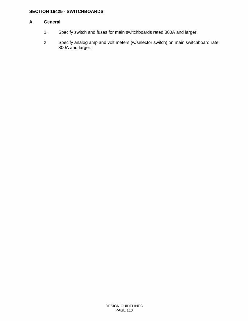
DESIGN GUIDELINES PAGE 113
SECTION 16425 - SWITCHBOARDS A. General 1. Specify switch and fuses for main switchboards rated 800A and larger. 2. Specify analog amp and volt meters (w/selector switch) on main switchboard rate
800A and larger.

DESIGN GUIDELINES PAGE 114
SECTION 16452 - GROUNDING A. General 1. Provide a separate equipment grounding conductor (green wire) in all raceway
and cable. 2. Provide separate ground bus in all distribution equipment. 3. Detail electric service entrance grounding on drawings. 4. Detail computer room grounding on drawings. 5. Thermo-weld all ground connection below grade.

DESIGN GUIDELINES PAGE 115
SECTION 16460 - TRANSFORMERS A. General 1. Dry-type distribution general purpose transformers. a. Provide 2-1/2% taps on dry type transformers two above and four below. 2. The designer shall evaluate the anticipated building harmonics to determine the
K rating for each transformer. 3. Rebuilt transformer are unacceptable.

DESIGN GUIDELINES PAGE 116
SECTION 16470 - PANELBOARDS A. General 1. Specify bolt-on breaker branch circuit panels. 2. Provide for minimum 25% spare branch circuit spaces in new panel boards. 3. Load centers shall not be allowed.

DESIGN GUIDELINES PAGE 117
SECTION 16477 - FUSES A. General 1. Specify fuses to be Buss with equal by Gould or Reliance. 2. As much as possible, equipment should be specified with class R fuse holds and
class R fuses specified. 3. Specify one set of three spare fuses for each type and size fuse on the project. 4. For projects with ten (10) or more spare fuses, specify a cabinet for storage of
the spare fuses. The cabinet shall be metal designed to store fuses, mounted in a highly visible location and labeled appropriately.
5. Fuse size shall be selected for ‘selective coordination” in addition to overload and
short circuit protection.

DESIGN GUIDELINES PAGE 118
SECTION 16481 - MOTOR CONTROLLERS A. General 1. All motors above 20HP shall have phase loss protection.

DESIGN GUIDELINES PAGE 119
SECTION 16495 - AUTOMATIC TRANSFER SWITCHES A. General 1. Automatic transfer switches utilizing components of knife switches, safety
switches, molded-case circuit breakers, contractors, or parts thereof are not acceptable.
2. Determine need and specify “inphase monitor controls” for retransfer of large
motors or motor with high inertia loads.

DESIGN GUIDELINES PAGE 120
SECTION 16515 - INTERIOR LIGHTING A. General 1. All spaces shall be designed to foot-candle levels as recommended by the latest
edition of IES lighting handbook, except mechanical and electrical equipment rooms shall have 40 foot-candles minimum.
2. Specify only light fixtures which use standard lamps. Keep number of different
lamp types to a minimum. 3. Keep use of incandescent laps to a minimum, use compact fluorescent where
possible. 4. In addition to exit and egress emergency lighting, provide emergency lighting in
public restrooms and essential mechanical spaces. 5. Use fluorescent light fixture in all areas unless design dictates otherwise. 6. Fluorescent lamps shall be F32T8/35K, rapid start with medium Bipin base and
3500 degree kelvin. 7. Ballast shall be T8 magnetic or T8 electronic.

DESIGN GUIDELINES PAGE 121
SECTION 16525 - EXTERIOR LIGHTING A. General 1. All exterior lighting systems shall comply with IES Lighting Handbook’s
recommended foot-candle levels. 2. Exterior lighting shall be high pressure sodium vapor in all areas except metal
halide may be used for lighting signs or other displays. 3. Exterior lighting systems will use photocells as the primary control system. Time
clocks will be provided when additional savings can be achieved by limiting the hours of use to less than the hours of darkness.
4. All parking lots must be provided with lighting, photocell controlled.

DESIGN GUIDELINES PAGE 122
SECTION 16620 - PACKAGED ENGINE GENERATOR SYSTEMS A. General 1. Specify full load bank test on new engine generator installations over 400 kva.

DESIGN GUIDELINES PAGE 123
SECTION 16721 - FIRE ALARM SYSTEMS A. General 1. All new building and major renovations shall include a central, zoned fire alarm
system. 2. All fire alarm systems shall comply with ADA. 3. All fire alarm panels shall e equipped with a “walk test” feature. This allows each
activating device to be tested without the need to reset the panel after each device is activated.
4. Drawings for fire alarm systems shall include zoning and locations for each
device on the plan view and a riser diagram. 5. Specifications to require full system test with written report by factory trained
certified technician.

DESIGN GUIDELINES PAGE 124
SECTION 16750 - TELEPHONE SYSTEMS A. General 1. The telephone terminal board shall be a sheet of new 3/4 inch plywood with size
shown on drawing. The plywood shall be finished on one side and on all edges. Finish shall be two coats of gray enamel paint. The plywood shall be mounted on a wall with minimum of three feet working clearance.
2. The telephone terminal board shall have a ground bar tied to the facility service
entrance ground with a #6 CU wire and a 4-plex receptacle on one side or below the board.