structures design guidelines for load … design guidelines for load and resistance factor design...
TRANSCRIPT
STRUCTURES DESIGN GUIDELINES FOR
LOAD AND RESISTANCE FACTOR DESIGN
STRUCTURES DESIGN OFFICE TALLAHASSEE, FLORIDA
AUGUST 2002

Structures Design Guidelines Summary of Changes-Aug 2002
1
Minor grammatical changes throughout guidelines. Chapter 1 1.4.4 Exterior Holes Added information on drains and drain locations. Deleted Section 1.5 Special Requirements for Movable Bridges because AASHTO LRFD now covers movable bridges. Created new section "1.7 Special Requirements for Post-Tensioned Bridges" which requires detailing post-tensioning in regard to corrosion. Chapter 2 Revised Name to "Environmental Classification and Material Criteria" 2.3.1, A., added item "3.) Sulfates less than 150 ppm." Table 2.2 Minimum Concrete Cover - deleted footnote numbers Table 2.3 Structural Concrete Class – Revised for Class V(Spec). Added 2.9 "Post-Tensioned Structures" (covers levels of strand protection) Chapter 3 Revised Table 3.1 Miscellaneous Loads Revised Eq. 3-2. Added Section 3.12 Pedestrian Live Loads on Pedestrian Bridges. Chapter 4 4.3 General Foundation Considerations, revised condition for minimum 24” pile. Revised Table 4.3 Pile Data Table Chapter 5 Deleted 5.3.1 Secondary Reinforcing Requirements for Pier Footings. Revised 5.4 Design Considerations in Piers, Columns, and Footings Chapter 6 Revised 6.5 General Policy for Joint Devices adding paragraph requiring silicone seals on C-I-P flat slab bridges. Section 6.7 deleted paragraph reading "Movements of longitudinally post-tensioned segmental concrete bridges due to temperature variation shall be calculated according to the requirements of Chapter 7." Revised 6.13 Control of Shrinkage Cracking in Continuous Superstructures to require min 72 hours between deck pours.
Structures Design Guidelines Summary of Changes-Aug 2002
2
Chapter 7 Added the following to 7.1 General "When using Florida limerock coarse aggregate, use 90% of the value calculated for the Modulus of Elasticity in LRFD 5.4." 7.2.2 Deck Thickness Determination Added reference to Chapter 2 for “Stay-in-place form restrictions” Deleted section "Design Loading" Revised syntax and typos in "7.3.4 Transverse Slab Reinforcement [9.7.1.3] Deleted section 7.4.1 “1.6 multiplier for strand development now included in AASHTO LRFD” "7.5 Precast Prestressed Slab Units" Added paragraph concerning corrosion protection for post-tensioning. Revised chapter to create a Post-Tensioning section with sub-sections for segmental box and I-Girder construction. Added revisions concerning tendon requirements such as minimum number, protection against corrosion. Deleted Section "Design of Continuous Prestressed Concrete I-Girder Superstructures." Equation 7-5 Revised Equation 7-6 deleted (c/10d) Equation 7-8 "0.0178" changed to ". 4534" 7.14.2 Notation – Revised 7.14.3 Design Requirements for Tensile Loading – Revised Revised Adhesive Anchors Revised graphics for adhesive anchor examples. Chapter 8 Revised 8.10 Transverse Intermediate Stiffeners. Deleted 8.15 Size of Bolts. (This information was placed in 8.3 Bolts) Deleted 8.19 Steel Sheet Piling Chapter 10 Added requirement for temporary shoring of counterweight prior to pouring. Added requirement for bolted and machined connection between rack and girder. Revised grammar for misc. sections in fasteners. �

Topic No.: 625-020-154-b Effective: Aug 1, 2002 Structures Design Guidelines (LRFD)
Table of Contents
INTRODUCTION CHAPTER 1 GENERAL REQUIREMENTS CHAPTER 2 ENVIRONMENTALCLASSIFICATION CHAPTER 3 LOADS AND LOAD FACTORS CHAPTER 4 FOUNDATIONS CHAPTER 5 SUBSTRUCTURECHAPTER 6 SUPERSTRUCTURE CHAPTER 7 CONCRETE STRUCTURES CHAPTER 8 STEEL BRIDGE STRUCTURES CHAPTER 9 WIDENING AND REHABILITATION CHAPTER 10 MOVABLE BRIDGES CHAPTER 11 BRIDGE COST ESTIMATING

Topic No: 625-020-154-b Effective Aug 1, 2002 Structures Design Guidelines (LRFD)
INTRODUCTION
I.1 Purpose........................................................................................... 2
I.2 Authority ......................................................................................... 2
I.3 Scope.............................................................................................. 2
I.4 General............................................................................................ 2
I.5 Referenced Documents..................................................................... 2
I.6 Abbreviations................................................................................... 3
I.7 Distribution...................................................................................... 3
I.8 Registration ..................................................................................... 3
I.9 Administrative Management .............................................................. 3
I.10 Modifications And Improvements..................................................... 4
I.11 Adoption of Revisions..................................................................... 4
I.12 Training ......................................................................................... 6
I.13 Forms ............................................................................................ 6
Introduction I-1


Topic No: 625-020-154-b Effective Aug 1, 2002 Structures Design Guidelines (LRFD)
INTRODUCTION STRUCTURES DESIGN GUIDELINES
I.1 Purpose The Structures Design Guidelines (SDG), sets forth the basic Florida Department of Transportation (FDOT) design criteria that are exceptions to those included in the AASHTO/LRFD Bridge Design Specifications published in Customary U.S. Units by the American Association of State Highway and Transportation Officials (AASHTO) for Load and Resistance Factor Design (LRFD), and hereinafter simply referred to as “LRFD.” These exceptions may be in the form of deletions from, additions to, or modifications of the LRFD specifications. AASHTO/LRFD and the Structures Design Guidelines (SDG) must always be used jointly and in concert with the FDOT’s Plans Preparation Manual (PPM) in order to properly prepare the contract plans and specifications for structural elements and/or systems that are included as part of the construction work in FDOT projects. Such elements and/or systems include, but are not necessarily limited to, bridges, overhead sign structures, earth retaining structures, and miscellaneous roadway appurtenances.
I.2 Authority Section 334.044(2), Florida Statutes.
I.3 Scope The use of this manual is required of anyone performing structural design or analysis for the Florida Department of Transportation.
I.4 General This manual consists of text, figures, charts, graphs, and tables as necessary to provide engineering standards, criteria, and guidelines to be used in developing and designing structures for which the Structures Design Office (SDO) and District Structures Design Offices (DSDO) have overall responsibility. The manual is written in the same general format and specification-type language as LRFD and includes article-by-article commentary when appropriate. In addition to its companion documents referenced in Article I.1 above, the manual is intended to complement and be used in conjunction with the SDO's Detailing Manual, Standard Drawings, CADD User's Manual, and the Standard Specifications for Road and Bridge Construction.
I.5 Referenced Documents Other FDOT Manuals referenced in this document include:
Introduction I-2

Topic No: 625-020-154-b Effective Aug 1, 2002 Structures Design Guidelines (LRFD)
Plans Preparation Manual, Volume 1 (Topic No.: 625-000-007) Plans Preparation Manual, Volume 2 (Topic No.: 625-000-008) Detailing Manual (Topic No.: 625-020-200) Drainage Manual (Topic No.: 625-040-001) Standard Drawings (Topic No.: 625-020-300) CADD User's Manual
I.6 Abbreviations AASHTO American Association of State Highway and Transportation Officials DSDE District Structures Design Engineer DSDO District Structures Design Office FHWA Federal Highway Administration FDOT Florida Department of Transportation LRFD Load and Resistance Factor Design PPM Plans Preparation Manual SDG Structure Design Guidelines SDO Structures Design Office SSDE State Structures Design Engineer TAG Technical Advisory Group TDB Temporary Design Bulletin
I.7 Distribution This SDG is furnished via the SDO web page at no charge. It is the responsibility of the designer to regularly check for additions, modifications and bulletins. Questions regarding this manual and any modifications may be obtained from the following office and address: Structures Design Office Mail Station 33 605 Suwannee Street Tallahassee, Florida 32399-0450 Tel.: (850) 414-4255 http://www11.myflorida.com/structures
I.8 Registration This manual no longer contains a registration page. It is incumbent upon the user to keep abreast of changes via the SDO web page.
I.9 Administrative Management Administrative Management of the Structures Design Guidelines (SDG) is a cooperative effort of SDO staff and the nine voting members of the Technical Advisory Group (TAG).
Introduction I-3

Topic No: 625-020-154-b Effective Aug 1, 2002 Structures Design Guidelines (LRFD)
I.9.1. The Technical Advisory Group (TAG) The TAG provides overall guidance and direction for the SDG and has the final word on all proposed modifications. The TAG comprises the State Structures Design Engineer (SSDE) and the eight District Structures Design Engineers (DSDE). In matters of technical direction or administrative policy, when unanimity cannot be obtained, each DSDE has one vote, the SSDE has two votes, and the majority rules. I.9.2. SDO Staff SDO Staff comprises the Assistant State Structures Design Engineers and Senior Structures Design Engineers selected by the SSDE.
I.10 Modifications And Improvements All manual users are encouraged to suggest modifications and improvements to the SDG. Modifications to the manual are the direct result of changes in FDOT specifications, FDOT organization, Federal Highway Administration (FHWA) regulations, and AASHTO requirements; or occur from recent experience gained during construction, through maintenance, and as a result of research. Users have suggested many other improvements to the manual. This has been particularly true with suggestions to improve the clarity of the text and to include design criteria not previously addressed by the manual or by any accompanying code or specification. Transmit, suggestions in writing to the State Structures design Engineer, 605 Suwannee St, (ms 33), Tallahassee, FL 32399
I.11 Adoption of Revisions Revisions to the SDG are issued by the SDO as Temporary Design Bulletins or Permanent Revisions according to a formal adoption process. Temporary Design Bulletins provide the SDO with the flexibility to quickly address any modification considered by the SDO to be essential to production or structural integrity issues. I.11.1. Temporary Design Bulletins A Temporary Design Bulletin (TDB) is a revision to the SDG that is deemed by the SSDE to be mandatory and in need of immediate implementation. TDB’s may address issues in plans production, safety, structural design methodology, critical code changes, or new specification requirements. TDB’s supercede the requirements of the current version of the SDG and may be issued at any time. TDB’s are not official or effective until signed by the State Structures Design Engineer. TDB’s are effective for up to 360 calendar days unless superceded by subsequent TDB’s or Permanent Revisions to the SDG. TDB’s automatically become proposed Permanent Revisions unless withdrawn from consideration by the SSDE. Introduction I-4
Topic No: 625-020-154-b Effective Aug 1, 2002 Structures Design Guidelines (LRFD)
TDB’s indicate their effective date of issuance, include the reference Topic Number, are numbered sequentially with reference to both the SDG version number and year of issuance. For example, Temporary Design Bulletin No. C98-2 would be the second Bulletin issued in 1998 for SDG. I.11.2. Permanent Revisions Permanent Revisions to the manual are made semi-annually or "as-needed." If the SDO considers an individual revision, or an accumulation of revisions, to be substantive, the manual will be completely reprinted. The following steps are required for adoption of a revision to the manual. A. Revision Assessment
SDO Staff will assess proposed revisions and develop the initial draft of all proposed SDG modifications for the SSDE’s approval.
B. Revision Research and Proposal The SDO Staff will conduct the necessary research, coordinate the proposed modification with all other affected offices and, if the proposed modification is deemed appropriate, prepare a complete, written modification with any needed commentary. The SSDE’s approval signifies the SDO’s position on the proposed modifications.
C. Revision Distribution To TAG and Other Review Offices Proposed modifications will be mailed to TAG members and others allowing for no less than two weeks review time before the next scheduled TAG meeting. Other parties include, but are not limited to: State Construction Office, State Maintenance Office, State Materials Office, State Roadway Design Office, Organization, Forms and Procedures, and FHWA.
DSDE members of TAG will coordinate the proposed modifications with all other appropriate offices at the district level.
D. Revision Review by TAG and SDO
Each TAG member will review proposed modifications prior to the meeting where they will be brought forward for discussion The SDO will review all modification comments received from other FDOT/FHWA offices in preparation for presentation at the meeting.
Additional review comments received by the SDO and/or DSDO’s during the review process will be presented for discussion and resolution.
Introduction I-5

Topic No: 625-020-154-b Effective Aug 1, 2002 Structures Design Guidelines (LRFD)
Introduction I-6
E. TAG Adoption Recommendation Immediately after the TAG meeting, each proposed modification will be returned to the SDO with one of the following recommendations: 1.) Recommended for adoption as presented. 2.) Recommended for adoption with resolution of specific changes. 3.) Not recommended for adoption.
F. Revision Recommendations to SSDE
Within two weeks after the TAG meeting, the SDO Staff will resolve each recommended modification and the assembled modifications will be provided to the SSDE for final approval.
G. Revision Adoption and Implementation Once approved by the SSDE, the SDG revision modifications will be assigned to the Design Technology Group Leader for final editing.
H. Official Distribution of Revisions as New SDG Version Unless agreed otherwise, the SDG version modifications will be distributed within 4 weeks after receipt of the approved modifications from the SSDE. This time frame allows the Organization and Procedures Office to update the Standard Operating System and any electronic media prior to electronic distribution of the SDG.
I.12 Training No specific training is necessary for the use of this manual. Major revisions are often presented and discussed at the Biennial Structures Design Conference.
I.13 Forms This manual requires no forms.


Topic No: 625-020-154-b Effective: Aug 1,2002 Structures Design Guidelines (LRFD)
CHAPTER 1
GENERAL REQUIREMENTS
1.1 Introduction ................................................................................................1
1.2 Format.........................................................................................................1
1.3 Coordination...............................................................................................1
1.4 Box Girder Inspection and Access Requirements..................................1 1.4.1 Box Girder Height [2.5.2.6.3].....................................................................2 1.4.2 Electrical Service ......................................................................................2 1.4.3 Inspection and Maintenance Access.........................................................2 1.4.4 Exterior Holes ...........................................................................................2 1.4.5 Steel Box Girder Interior Painting..............................................................2 1.4.6 Inspection and Access Requirements of Other Box Sections ...................3
1.5 Existing Structures with Hazardous Material ..........................................3
1.6 Special Requirements for Post-Tensioned Bridges................................3
General Requirements 1-i


Topic No: 625-020-154-b Effective: Aug 1,2002 Structures Design Guidelines (LRFD)
CHAPTER 1 GENERAL REQUIREMENTS
1.1 Introduction These Structures Design Guidelines, (SDG) incorporate technical design criteria only and supersede the requirements of the AASHTO/LRFD Bridge Design Specifications, Second Edition (1998 with latest interim standards), hereinafter referred to as “LRFD,” either by additions, deletions, or modifications. The SDG supplements the technical design requirements of LRFD for bridges and structures for the Florida Department of Transportation, and facilitates the plans production process for the Department. All general administrative, geometric, shop drawing, and plans processing requirements have been incorporated in the Plans Preparation Manual (PPM)(Topic No.: 625-000-007.) The SDG are written to designers of bridges and structures for the Florida Department of Transportation.
1.2 Format The SDG chapters are organized more by “component,” “element,” or “process” than by “material” as for the LRFD. As a result, the chapter numbers and content of the SDG do not necessarily align themselves in the same order or with the same number as LRFD. However, LRFD references are provided whenever possible so that the designer may quickly coordinate and associate SDG criteria with that of LRFD. The LRFD references may occur within article descriptions, the body of the text, or in the commentary. Such references are shown in bold-face type within brackets; i.e., [1.3], [8.2.1], etc.
1.3 Coordination Coordinate all plans production activities and requirements between the SDG, PPM, and LRFD. Each of these documents has criteria pertaining to bridge or structures design projects, and, normally, all three must be consulted to assure proper completion of a project for the Department. Direct all questions concerning the applicability or requirements of any of these or other referenced documents to a the appropriate Structures Design Engineer.
1.4 Box Girder Inspection and Access Requirements During preliminary engineering and when determining structure configuration, give utmost consideration to accessibility and to the safety of bridge inspectors and maintenance.
General Requirements 1-1
Topic No: 625-020-154-b Effective: Aug 1,2002 Structures Design Guidelines (LRFD) 1.4.1 Box Girder Height [2.5.2.6.3] For maintenance and inspection, the minimum interior, clear height of box girders is 6 feet. Proposed heights less than 6 feet will require approval from the SDO. If structural analysis requires less than 5 feet box depth, consult the SDO and the District Structures and Facilities Engineer for a decision on the box height and access details. 1.4.2 Electrical Service Design box girder bridges with interior lighting and electrical outlets in all boxes and detail in accordance with SDO’s Standard Drawings. 1.4.3 Inspection and Maintenance Access Design box girders with exterior, in-swinging, hinged, doors (min. 32”x42” or 36” dia). Equip doors with a lock and hasp. Require that all locks be keyed alike. Indicate on plans that access openings are not to be used for utilities or other attachments. Analyze access opening sizes and bottom flange locations for structural effects on the girder. Avoid access locations over traffic lanes and locations that will require extensive maintenance of traffic operations or that would otherwise impact the safety of inspectors or the traveling public. 1.4.4 Exterior Holes Design each box girder with minimum 2” diameter ventilation or drain holes spaced about every 50 feet or as needed to provide proper drainage. Require .25” screen on all exterior holes not covered by a door. This includes holes in webs through which drain pipes pass, ventilation holes, drain holes, and openings in diaphragms at abutments and at expansion joints. Provide drains through the bottom slab in box girder bridges to prevent water that enters from any source, including condensation, from ponding in the vicinity of post-tensioning components. Show details on Contract Drawings. Include the following: A. Specify that drains may be formed using 2 inch diameter permanent plastic pipes
(PVC with UV inhibitor) set flush with the top of the bottom slab. B. A small drip recess, ½ inch by ½ inch around bottom of pipe insert. C. Drains at all low points against internal barriers, blisters, etc. D. Drains on both sides of box, regardless of cross slope (to avoid confusion.) E. Show locations and details for drains taking into account bridge grade and cross-
slope. F. Vermin guards for all drains. G. A note stating, “The Contractor shall install similar drains at all low spots made by
barriers introduced to accommodate his means and methods of construction, including additional blocks or blisters.”
1.4.5 Steel Box Girder Interior Painting When structural steel is to be painted, specify white or gray color for the interior of box girders. Zinc primer is acceptable for finish color.
General Requirements 1-2
Topic No: 625-020-154-b Effective: Aug 1,2002 Structures Design Guidelines (LRFD)
General Requirements 1-3
1.4.6 Inspection and Access Requirements of Other Box Sections Provide accessibility to box sections such as precast hollow pier segments in a manner similar to that for box girders, particularly concerning the safety of bridge inspectors and maintenance personnel. During preliminary engineering and when determining structure configuration, give utmost consideration to box girder accessibility and the safety of bridge inspectors and maintenance personnel. Due to the wide variety of shapes and sizes of hollow sections such as precast concrete pier segments, numerous site constraints and environmental conditions, each application will be considered on an individual, project-by-project basis. In all cases, contact the SDO for guidance in designing adequate inspection access and safety measures. Precast, pretensioned Florida U-beams are exempted from special requirements for inspection and access.
1.5 Existing Structures with Hazardous Material Comply with the regulations of the Occupational Safety and Health Administration (OSHA) and the Environmental Protection Agency (EPA) for the handling and disposal of hazardous materials. Survey project to determine if an existing structure contains hazardous materials such as lead-based paint, asbestos-graphite bearing pads, etc. Information will be provided by the Department or by site testing to make this determination. When an existing structure has been identified as having hazardous material, no project will be developed without adequate provisions for worker safety, handling, storage, shipping, and disposal of the hazardous material. If proposed work will disturb identified hazardous materials, include in the project documents, protection, handling, and disposal requirements. When a project involves hazardous materials, the FDOT design project manager will provide assistance in preparing the construction documents and will provide the technical special provisions for handling and disposing of hazardous materials. NOTE: No project on which any existing structure contains hazardous material shall be developed without adequate provisions for worker safety, handling, storage, shipping, and disposal of the hazardous material and/or its waste.
1.6 Special Requirements for Post-Tensioned Bridges Detail all Post-tensioned bridges consistent with the Specifications and Standards and include the following five strategies: A. Enhanced Post-tensioned systems. B. Fully grouted tendons. C. Multi-level anchor protection. D. Watertight bridges. E. Multiple tendon paths.

Topic No: 625-020-154-b Effective: Aug 1,2002 Structures Design Guidelines (LRFD)
CHAPTER 2 ENVIRONMENTAL CLASSIFICATION
AND MATERIAL CRITERIA
2.1 General ........................................................................................................2-1
2.2 Establishment of Environmental Classification ............................................2-1
2.3 Definition of Environmental Classification ....................................................2-2 2.3.1 Substructure for the conditions of the soil and/or water:.........................2-2 2.3.2 Superstructure........................................................................................2-2 2.3.3 Substructure and Superstructure Definitions..........................................2-2 2.3.4 Chloride Content Determinations ...........................................................2-3
2.4 Concrete Structures [5.12.1] ........................................................................2-3 2.4.1 Concrete Cover ......................................................................................2-3 2.4.2 Concrete Class and Admixtures for Corrosion Protection ......................2-4 2.4.3 Penetrant Sealers...................................................................................2-5
2.5 Stay-in-Place Forms ....................................................................................2-5
2.6 Epoxy Coated Reinforcing Steel ..................................................................2-5
2.7 Construction Joints in Drilled Shafts ............................................................2-6
2.8 Steel Structures ...........................................................................................2-6 2.8.1 Corrosion Protection System..................................................................2-6 2.8.2 Uncoated Weathering Steel ...................................................................2-6 2.8.3 Superstructure Joint and Drainage Considerations: ...............................2-6 2.8.4 Single Coat Inorganic Zinc Coating ........................................................2-6 2.8.5 Galvanizing ............................................................................................2-7
2.9 Post-tensioned Structures............................................................................2-7 2.9.1 Three levels of Strand Protection. ..........................................................2-7 2.9.2 Four Levels of Anchorage Protection .....................................................2-8
Env Classification and Material Criteria 2-i


Topic No: 625-020-154-b Effective: Aug 1,2002 Structures Design Guidelines (LRFD)
CHAPTER 2
ENVIRONMENTAL CLASSIFICATION
AND MATERIAL CRITERIA
2.1 General This Chapter clarifies, supplements, and contains deviations from the information in LRFD Sections [2], [5], and [6]. These combined requirements establish material selection criteria for durability to meet the 75-year design life requirement established by the Department.
2.2 Establishment of Environmental Classification The District Materials Engineer or the Department’s Environmental/Geotechnical Consultant will environmentally classify all new bridge sites. Environmental classification may be required for minor widenings and is required for major widenings (see definitions in Chapter 9). This determination will be made prior to or during the development of the Bridge Development Report (BDR)/30% Plans Stage, and the results will be included in the documents. The bridge site will be tested, and separate classifications determined for superstructures and substructures. In the bridge plan “General Notes,” include the environmental classification for both the superstructure and substructure according to the following classifications:
1.) Slightly Aggressive 2.) Moderately Aggressive 3.) Extremely Aggressive
For the substructure, additional descriptive data supplements the environmental classification. After the classification, note in parentheses, the source and magnitude of the environmental classification parameter(s) resulting in the classification. Commentary: As an example, for a proposed bridge located in a freshwater swampy area where the substructure is determined to be in an Extremely Aggressive environment due to low soil pH of 4.5 and the superstructure to be in a Slightly Aggressive environment, the format on the bridge plans will be: ENVIRONMENTAL CLASSIFICATION: Substructure: Extremely Aggressive (Soil - pH = 4.5) Superstructure: Slightly Aggressive
Env Classification and Material Criteria 2-1

Topic No: 625-020-154-b Effective: Aug 1,2002 Structures Design Guidelines (LRFD) 2.3 Definition of Environmental Classification Bridge substructure and superstructure environments will be classified as Slightly Aggressive, Moderately Aggressive, or Extremely Aggressive environments according to the following criteria. 2.3.1 Substructure for the conditions of the soil and/or water: A. Slightly Aggressive when all of the following conditions exist:
1.) pH greater than 6.6. 2.) Resistivity greater than 3,000 ohm-cm. 3.) Sulfates less than 150 ppm. 4.) Chlorides less than 500 ppm.
B. Moderately Aggressive: This classification shall be used at all sites not meeting requirements for either Slightly Aggressive or Extremely Aggressive Environments.
C. Extremely Aggressive when any one of the following conditions exists: 1.) For concrete structures: pH less than 5.0. 2.) For steel structures: pH less than 6.0. 3.) Resistivity less than 500 ohm-cm. 4.) Sulfates greater than 1,500 ppm. 5.) Chlorides greater than 2,000 ppm.
2.3.2 Superstructure The following environmental classifications apply: A. Slightly Aggressive:
Any superstructure situated in an environment that is not classified either as Moderately or Extremely Aggressive (see Figure 2-1).
B. Moderately Aggressive: Any superstructure located within 2,500 ft. of any coal burning industrial facility, pulpwood plant, fertilizer plant or any other similar industry where, in the opinion of the District Materials Engineer, a potential environmental corrosion condition exists, or any other specific conditions and/or locations described in Figure 2-1.
C. Extremely Aggressive: Any superstructure situated in an area such that a combination of environmental factors indicates that significant corrosion potential exists, or with specific conditions and/or locations described in Figure 2-1.
2.3.3 Substructure and Superstructure Definitions The division between the substructure and the superstructure is stated in the FDOT Standard Specifications for Road and Bridge Construction, Section 1, except as noted below.
Env Classification and Material Criteria 2-2

Topic No: 625-020-154-b Effective: Aug 1,2002 Structures Design Guidelines (LRFD) A. Box culverts, retaining wall systems (including MSE walls), sound barriers on
structures and bulkheads are substructures. B. The substructure will not be classified less severely than the superstructure. C. Approach slabs are superstructure; however, Class II Concrete (Bridge Deck)
will be used for all environmental classifications. 2.3.4 Chloride Content Determinations A. The District Materials Engineer will determine the chloride content of the water
and soil at the proposed bridge site. B. The chloride content of major bodies of water within 2,500 feet of the proposed
bridge site will, in most instances, be available in the Department's Bridge Corrosion Analysis database. In the unlikely event chloride values are unavailable, the major body of water must be tested unless it is known to be a freshwater body.
C. Generally, all superstructures that are within line-of-sight and within 2,500 feet of the Atlantic Ocean or the Gulf of Mexico are subject to increased chloride intrusion rates on the order of 0.0016 lbs/cy/year at a 2-inch concrete depth. The intrusion rate decreases rapidly with distance from open waters and/or when obstacles such as rising terrain, foliage or buildings alter wind patterns. In order to optimize the materials selection process, the Designer and/or District Materials Engineer have the option of obtaining representative cores to determine chloride intrusion rates for any superstructure within 2,500 feet of any major body of water containing more than 12,000-ppm chlorides. The District Materials Engineer will take core samples from bridge superstructures in the immediate area of the proposed superstructure. The sampling plan with sufficient samples representing the various deck elevations will be coordinated with the State Corrosion Engineer. The Corrosion Laboratory of the State Materials Office will test core samples for chloride content and intrusion rates.
After representative samples are taken and tested, Table 2.1 will be used to correlate the core results (the chloride intrusion rate in lbs/cy /year at a depth of 2 inch) with the classification.
Table 2.1 Chloride Intrusion Rate/Environmental Classification
CHLORIDE INTRUSION RATE CLASSIFICATION > 0.0016 lbs/cy/year Extremely Aggressive < 0.0016 lbs/cy/year Moderately Aggressive
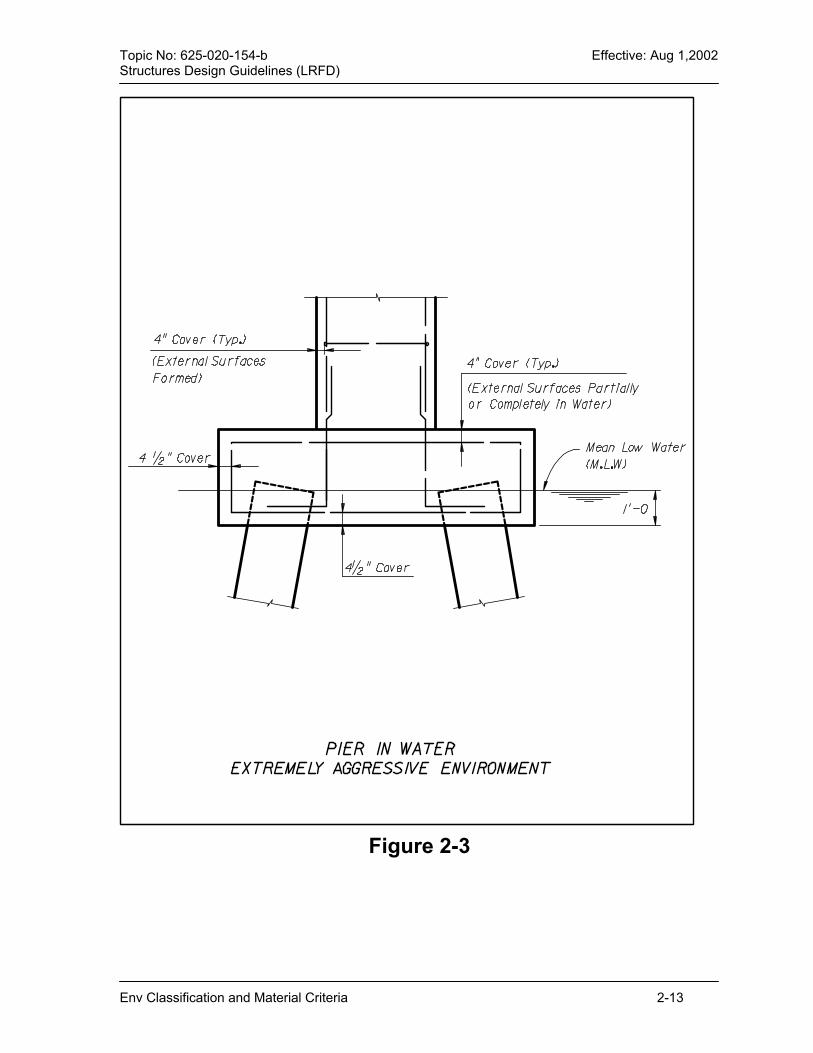
2.4 Concrete Structures [5.12.1] 2.4.1 Concrete Cover Delete AASHTO LRFD Article 5.12.3 and substitute the following requirements: The requirements for concrete cover over reinforcing steel are listed in Table 2.2. Examples of concrete cover are shown in Figures 2.2 through 2.5.
Env Classification and Material Criteria 2-3

Topic No: 625-020-154-b Effective: Aug 1,2002 Structures Design Guidelines (LRFD) When deformed reinforcing bars are in contact with other embedded items such as post-tensioning ducts, the actual bar diameter, including deformations, must be taken into account in determining the design dimensions of concrete members and in applying the design covers of Table 2.2. 2.4.2 Concrete Class and Admixtures for Corrosion Protection The “General Notes” for both bridge plans and wall plans require the clear identification of, and delineation of use for, concrete class and admixtures used for strength and durability considerations. A. Concrete Class Requirements:
When the environmental classifications for a proposed structure have been determined, those portions of the structure located in each classification will be built with the class of concrete described in Table 2.3 for the intended use and location unless otherwise directed or approved by the Department.
Unless otherwise specifically designated or required by the FDOT, the concrete strength utilized in the design shall be consistent with the 28-day compressive strength given in the FDOT Standard Specification Section 346.
Commentary: Example: Component - submerged piling Environment - Extremely Aggressive over saltwater Concrete Class - Table 2.3 Class V (Special) Quality Control and Design Strength at 28 days - 6,000 psi
B. Admixtures for Corrosion Protection:
Primary components of structures located in Moderately or Extremely Aggressive environments utilize Class IV, V, V (Special), or VI Concrete. These concrete classes use fly ash, slag, microsilica, and/or cement type to reduce permeability.
Structures located in Extremely Aggressive marine environments may require additional measures as defined below. These additional measures and their location must be clearly identified in the “General Notes”. Technical Special Provisions to the specifications may be required for their implementation.
The use of concrete admixtures to enhance durability shall be consistent with these guidelines; however, if deemed necessary the Engineer of Record may request that additional measures be used. The State Corrosion Engineer and the State Structures Design Engineer must approve these additional measures. 1.) Corrosion Inhibitor - Calcium Nitrite:
When the environmental classification is Extremely Aggressive due to the presence of chloride in the water, specify calcium nitrite for the following conditions:
Env Classification and Material Criteria 2-4

Topic No: 625-020-154-b Effective: Aug 1,2002 Structures Design Guidelines (LRFD)
a.) In all superstructure components situated less than 12 feet above Mean High Water (MHW) .
b.) In all retaining walls, including MSE walls situated less than 12 feet above MHW and within 300 feet of the shoreline.
2.) Microsilica (Silica Fume): When the environmental classification is Extremely Aggressive due to the presence of chloride in the water, specify microsilica in the “splash zone” of all piles, columns or walls. Microsilica may be specified for the entire pile, column or wall but shall not be specified for drilled shafts. The splash zone is the 18-foot vertical distance from 6 feet below to 12 feet above MHW.
2.4.3 Penetrant Sealers On bridge widening projects where the existing bridge deck does not conform with the current reinforcing steel cover requirement and the superstructure environment is classified as Extremely Aggressive due to the presence of chlorides, and the existing deck is to be grooved, specify penetrant sealers for the existing bridge deck after grooving. Do not specify penetrant sealers for new bridge structures or if the existing deck is not to be grooved, Include in the bridge plans, an item in the “General Notes” and a sketch describing the concrete surfaces to be coated with penetrant sealer. For requirements for grooving widened bridges, refer to Chapter 9.
2.5 Stay-in-Place Forms Include in the "General Notes" for each bridge project, a note clearly stating whether or not Stay-in-Place Forms are permitted for the project and how the design was modified for their use; e.g., dead load allowance. Composite Stay-in-Place Forms are not permitted. A. Metal Stay-in-Place Forms:
Metal Stay-in-Place forms shall not be used in moderately aggressive or extremely aggressive environments; except, Metal Stay-in-Place forms may be used for the internal portions of box girders (closed portions between webs) without exception.
B. Concrete Stay-in-Place Forms: Concrete Stay-in-Place forms may be used for all environmental classifications without exception; however, the bridge plans must be specifically designed, detailed and prepared for their use.
2.6 Epoxy Coated Reinforcing Steel Epoxy coated reinforcing steel shall not be used in any bridge element or other highway related structure.
Env Classification and Material Criteria 2-5
Topic No: 625-020-154-b Effective: Aug 1,2002 Structures Design Guidelines (LRFD) 2.7 Construction Joints in Drilled Shafts Drilled shafts used in bents located in water containing more than 2000 ppm chloride shall be detailed to extend without a construction joint a minimum of 12 feet above the Mean High Water elevation or bottom of the bent cap, whichever is lower. Commentary: It is preferred that taller shafts extend to the bottom of the bent cap without a construction joint.
2.8 Steel Structures 2.8.1 Corrosion Protection System Specify uncoated weathering steel or a three-coat inorganic zinc coating system for corrosion protection. The use of any corrosion protection system other than the three coat inorganic zinc coating system requires the concurrence of the SDO or the DSDO. Final finish coat color is an aesthetic treatment and must be approved by the DSDO. 2.8.2 Uncoated Weathering Steel The design and use of weathering steel for bridges shall conform with the guidelines in FHWA Technical Advisory T5140.22 and the criteria stated herein. Suitable locations for the use of weathering steel without long-term, on-site panel testing shall be classified with an environmental classification of Slightly Aggressive for Superstructures (See Figure 2-1.) Weathering steel requires the use of ASTM A325 Type 3 bolts. Painting of the exterior girder/fascia may be required for aesthetic appearance. 2.8.3 Superstructure Joint and Drainage Considerations: A. Minimize the use of scuppers for deck drainage. Design scuppers or deck drains
to pipe drainage to the ground or use extended downspouts. B. Minimize the use of stiffeners and bracing and avoid crevices. 2.8.4 Single Coat Inorganic Zinc Coating Suitable locations for the use of single coat inorganic zinc coating without on site testing will meet or exceed the criteria stated herein. A. General Criteria: Environments classified as Slightly Aggressive for
Superstructure. B. Site Specific Criteria:
1.) Locations where the pH of the rainfall or condensation is between 4-10. 2.) Locations not subjected to salt spray or salt laden run-off. 3.) Locations not subjected to concentrated acid pollution caused by the
following sources: coal burning power plant; phosphate plant; acid manufacturing plant; any site yielding high levels of sulfur compounds.
Env Classification and Material Criteria 2-6

Topic No: 625-020-154-b Effective: Aug 1,2002 Structures Design Guidelines (LRFD) Commentary: Inorganic zinc coatings (either gray or green) quickly fade in approximately 3 months to a uniform gray color similar to Federal Color Standard Number 37866. For color, the fascia of the exterior girders can be coated with the three-coat inorganic zinc system. 2.8.5 Galvanizing A. Galvanizing of Bolts for Bridges:
Normally, all anchor bolts, tie-down hardware, and miscellaneous steel (ladders, platforms, grating, etc.) are to be hot-dip galvanized. While ASTM A307 (coarse thread) bolts shall be hot-dip galvanized, A325 (fine thread) bolts must be mechanically galvanized when utilized with galvanized steel components. Other applications not requiring full tensioning of the bolts may use hot-dip galvanized A325 bolts.
B. Galvanizing of Bolts for Miscellaneous Structures Specify hot-dipped galvanized bolts for connecting structural steel members of miscellaneous structures such as overhead sign structures, traffic mast arms, ground-mounted signs, etc.
2.9 Post-tensioned Structures Enhanced post-tensioning systems require three levels of protection for strand and four levels for anchorages. Note: Deck overlays are not considered a level of protection for strands or anchorages. 2.9.1 Three levels of Strand Protection (Within the Segment or Concrete Element) A. Internal Tendons.
1.) Concrete cover. 2.) Plastic duct. 3.) Complete filling of the duct with approved grout.
B. External Tendons 1.) Hollow box structure itself. 2.) Plastic duct. 3.) Complete filling of the duct with approved grout.
C. At the segment face or construction joint (Internal and External Tendons) 1.) Epoxy seal (pre-cast construction) or wet cast joint (cast-in-place
construction.) 2.) Continuity of the plastic duct. 3.) Complete filling of the duct with approved grout.
Env Classification and Material Criteria 2-7

Topic No: 625-020-154-b Effective: Aug 1,2002 Structures Design Guidelines (LRFD) 2.9.2 Four Levels of Anchorage Protection A. Anchorages located on interior surfaces (interior diaphragms, etc.)
1.) Grout. 2.) Permanent grout cap. 3.) Elastomeric seal coat. 4.) Concrete box structure.
B. Anchorages located on exterior surfaces (Pier Caps, expansion joints, diaphragms etc.) 1.) Grout. 2.) Permanent grout cap. 3.) Encapsulating pour-back. 4.) Seal coat (Elastomeric/Methyl Methacrylate on riding surface.)
Env Classification and Material Criteria 2-8

Topic No: 625-020-154-b Effective: Aug 1,2002 Structures Design Guidelines (LRFD) Table 2.2 Minimum Concrete Cover Requirements For Design and Detailing
CONCRETE COVER (in)ITEM DESCRIPTION
S or M* E* Superstructure (Precast)
Internal and external surfaces (except riding surfaces) of segmental concrete boxes, and external surfaces
of prestressed beams (except the top surface).
Top surface of girder top flange.
Top deck surfaces.Short Bridges***Long Bridges***
All components and surfaces not included above (including barriers).
2
1
2 2 ½**
2
2 1 2
2 ½** 2
Superstructure (Cast-in-Place)All external and internal surfaces (ex. top surfaces)
Top deck surfacesShort Bridges(***)
Long Bridges(***)
2
2 2 ½**
2 2
2 ½** Substructure (Cast-in-Place)
External surfaces cast against earth and surfaces in contact with water
External formed surfaces, columns, and tops of footings not in contact with water
Internal surfaces
Top of Girder Pedestals
4
3
3
2
4½ 4 3 2
Substructure (Precast) 3 4 Prestressed Piling (Including cylinder piling) 3 3
Drilled Shafts 6 6 Retaining Walls (Cast-in-Place or Precast) 2 3
Culverts (Cast-in-Place or Precast) 2 3 Bulkheads (Cast-in-Place) 4 4
NOTES: *S= Slightly Aggressive; M= Moderately aggressive; E= Extremely Aggressive. **Cover dimension includes a 0.5 inch allowance for milling. ***See Short & Long Bridge Definitions in Chapter 7.
Env Classification and Material Criteria 2-9
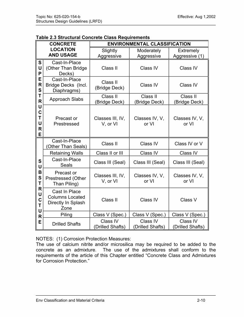
Topic No: 625-020-154-b Effective: Aug 1,2002 Structures Design Guidelines (LRFD) Table 2.3 Structural Concrete Class Requirements
ENVIRONMENTAL CLASSIFICATION CONCRETE LOCATION
AND USAGE Slightly
Aggressive Moderately Aggressive
Extremely Aggressive (1)
Cast-In-Place (Other Than Bridge
Decks) Class II Class IV Class IV
Cast-In-Place Bridge Decks (Incl.
Diaphragms)
Class II (Bridge Deck) Class IV Class IV
Approach Slabs Class II (Bridge Deck)
Class II (Bridge Deck)
Class II (Bridge Deck)
S U P E R S T R U C T U R E
Precast or Prestressed
Classes III, IV, V, or VI
Classes IV, V, or VI
Classes IV, V, or VI
Cast-In-Place (Other Than Seals) Class II Class IV Class IV or V
Retaining Walls Class II or III Class IV Class IV Cast-In-Place
Seals Class III (Seal) Class III (Seal) Class III (Seal)
Precast or Prestressed (Other
Than Piling)
Classes III, IV, V, or VI
Classes IV, V, or VI
Classes IV, V, or VI
Cast In Place Columns Located Directly In Splash
Zone
Class II Class IV Class V
Piling Class V (Spec.) Class V (Spec.) Class V (Spec.)
S U B S T R U C T U R E Drilled Shafts Class IV
(Drilled Shafts) Class IV
(Drilled Shafts) Class IV
(Drilled Shafts) NOTES: (1) Corrosion Protection Measures: The use of calcium nitrite and/or microsilica may be required to be added to the concrete as an admixture. The use of the admixtures shall conform to the requirements of the article of this Chapter entitled “Concrete Class and Admixtures for Corrosion Protection.”
Env Classification and Material Criteria 2-10

Topic No: 625-020-154-b Effective: Aug 1,2002 Structures Design Guidelines (LRFD)
Env Classification and Material Criter
NOTES: The height of 12 feet may brefers to the distance betwesurface at mean High Water (
Yes
Ismajor body
of water located lessthan 2500 feet from the
proposed bridgesite?
START HERE
Chloride content greater than 12,000 ppm?
No SLIGHTLY AGGRESSIVE
EXTREMELY AGGRESSIVEYes
No
Chloride content greater than 6,000 ppm?
Is the bridge over water?
No
Yes Yes
MODERATELY AGGRESSIVE
YesNo
Is theheight greater
than 12 feet? (1)
Is the chloride content greater than 2,000 ppm?
Is the bridge over water?
No
Yes Yes
No
SLIGHTLY AGGRESSIVE
YesNoNo
Is theheight greater
than 12 feet? (1)
Bridge Superstructure Figure 2-1
e increased for extreme exposure conditions. Heighten the lowest superstructure elevation and the waterMHW).
ia 2-11

Topic No: 625-020-154-b Effective: Aug 1,2002 Structures Design Guidelines (LRFD)
Figure 2-2
Env Classification and Material Criteria 2-12
Topic No: 625-020-154-b Effective: Aug 1,2002 Structures Design Guidelines (LRFD)
Figure 2-3
Env Classification and Material Criteria 2-13

Topic No: 625-020-154-b Effective: Aug 1,2002 Structures Design Guidelines (LRFD)
Figure 2- 4
Env Classification and Material Criteria 2-14

Topic No: 625-020-154-b Effective: Aug 1,2002 Structures Design Guidelines (LRFD)
Env Classification and Material Criteria 2-15
Figure 2-5


Topic No: 625-020-154-b Effective: Aug 1,2002 Structures Design Guidelines (LRFD)
CHAPTER 3 LOADS AND LOAD FACTORS
3.1 General ........................................................................................................3-1
3.2 Dead Loads..................................................................................................3-1
3.3 Seismic Provisions [3.10.9] [3.10.9.2] [4.7.4] ...............................................3-1 3.3.1 General 3-1 3.3.2 Seismic Design for New Construction ....................................................3-2 3.3.3 Seismic Design for Widenings................................................................3-2 3.3.4 Lateral Restraint.....................................................................................3-2
3.4 Wind Loads..................................................................................................3-2 3.4.1 Wind Loads on Bridges [3.8.1] ...............................................................3-2 3.4.2 Wind Loads on Other Structures ............................................................3-2 3.4.3 Wind Loads During Construction............................................................3-3
3.5 Miscellaneous Loads [3.5.1] ........................................................................3-3
3.6 Vehicular Collision Force [3.6.5] ..................................................................3-3
3.7 Uniform Temperature [3.12.2] ......................................................................3-3 3.7.1 Segmental Box Girders ..........................................................................3-3 3.7.2 Joints and Bearings................................................................................3-3 3.7.3 All Other Bridge Components.................................................................3-4 3.7.4 Temperature Gradient [3.12.3] ...............................................................3-4
3.8 Barrier/Railing Distribution for Beam-Slab Bridges [4.6.2.2] ........................3-4
3.9 Load Distribution Beam – Slab Bridges [4.6.2.2]..........................................3-5 3.9.1 Prestressed Concrete Inverted Tee Girder.............................................3-5 3.9.2 Prestressed Concrete “U” Girders.........................................................3-6
3.10 Operational Importance [1.3.5]...................................................................3-7
3.11 Vessel Collision [3.14]................................................................................3-8 3.11.1 General [3.14.1] ...................................................................................3-8 3.11.2 Research and Information Assembly ...................................................3-8 3.11.3 Design Vessel [3.14.4] [3.14.5.3] .........................................................3-9 3.11.4 Design Methodology - Damage Permitted [3.14.13].............................3-9 3.11.5 Pile Bents ...........................................................................................3-10 3.11.6 Widenings ..........................................................................................3-10 3.11.7 Movable Bridges ................................................................................3-10 3.11.8 Main Span Length ..............................................................................3-10 3.11.9 Scour with Vessel Collision [3.14.1] ...................................................3-10 3.11.10 Application of Impact Forces [3.14.14] .............................................3-11 3.11.11 Impact Forces on Superstructure [3.14.14.2] ...................................3-11
Loads and Load Factors 3-i

Topic No: 625-020-154-b Effective: Aug 1,2002 Structures Design Guidelines (LRFD)
3.11.12 Criteria for Deflection and Span-to-Depth Ratios [2.5.2.6] [3.6.1.3.2]3-11 3.11.13 Load Factors and Load Combinations [3.4.1]...................................3-11
3.12 Pedestrian Live Load on Pedestrian Bridges ...........................................3-11
Loads and Load Factors 3-ii
Topic No: 625-020-154-b Effective: Aug 1,2002 Structures Design Guidelines (LRFD)
CHAPTER 3 LOADS AND LOAD FACTORS
3.1 General This Chapter contains information related to loads, loadings, load factors, and load combinations. It also contains deviations from LRFD regarding Loads and Load Factors as well as characteristics of a structure that affect each.
3.2 Dead Loads A. Future Wearing Surface:
See Table 3.1 regarding the allowance for a Future Wearing Surface. B. Sacrificial Concrete:
Bridge decks subject to the profilograph requirements of Chapter 7 require an added thickness of sacrificial concrete, which must be accounted for as added Dead Load but which cannot be utilized for bridge deck section properties. See “Concrete Deck Slabs” in Chapter 7.
3.3 Seismic Provisions [3.10.9] [3.10.9.2] [4.7.4] 3.3.1 General
The majority of Florida bridges will not require seismic design or the design of restrainers. For such bridges, only the minimum bearing support dimensions need to be satisfied as required by LRFD [4.7.4.4]. Such bridges exempt from seismic design include those with superstructures comprising simple-span or continuous flat slabs, simple-span prestressed slabs or double-tees, simple-span AASHTO or Florida Bulb-Tee girders, and simple-span steel girders. Seismic design is required for unusual designs, continuous steel or concrete girders, steel or concrete box girders, concrete segmental bridges, curved bridges with a radius less than 1,000 feet, those that rely on a system of fixed or sliding bearings for transmitting elongation changes, spans in excess of 165 feet, cable supported bridges, and bridges that do not use conventional elastomeric bearing pads. Use the “Uniform Load Method” specified in LRFD [4.7.4.3.1] and [4.7.4.3.2], or any higher-level analysis, for calculating the seismic forces to be resisted by the bearings or other anchorage devices. Only the connections between the superstructure and substructure need to be designed for the seismic forces. Commentary: Neoprene bearing pads, as used in the majority of Florida bridges, have sufficient shearing strength and slip resistance to transfer the calculated seismic forces to the substructure. For most Florida bridges, seismic forces will not govern over other load combinations; however, for some designs, even where the acceleration coefficient is
Loads and Load Factors 3-1

Topic No: 625-020-154-b Effective: Aug 1,2002 Structures Design Guidelines (LRFD)
as low as 1%, seismic loads can govern. For example, a long continuous superstructure, supported on a system of sliding bearings at all piers except one short, stiff pier where fixed bearings are used. The fixed bearings, in such cases, must be designed to transmit the calculated seismic forces. These seismic forces will likely govern over other load cases. 3.3.2 Seismic Design for New Construction
When required for new construction as described above, use the single mode spectral method to determine the seismic design forces to be used for the restraint design between the superstructure and substructure only. Compare these forces to the values obtained using the simplified seismic Zone 1 method (LRFD 3.10.9.2). Use the lesser of the force values to design the seismic restraints. The acceleration coefficient in Florida varies from 1% to 3.75%, and shall be determined from the Map of Horizontal Acceleration contained in the latest edition of LRFD. 3.3.3 Seismic Design for Widenings
All bridge elements for a major widening (see definitions in SDG Chapter 9) must comply with the seismic provisions for new construction. Seismic provisions for minor widenings will be considered by the FDOT on an individual basis. 3.3.4 Lateral Restraint
When lateral restraint of the superstructure is required due to seismic loading, comply with the provisions and requirements of “Lateral Restraint of Superstructures” in Chapter 6.
3.4 Wind Loads 3.4.1 Wind Loads on Bridges [3.8.1]
Increase the wind pressures of LRFD by 20% for bridges located in Palm Beach, Broward, Dade, and Monroe counties. Submit wind pressures for bridges over 75 feet high or with unusual structural features, to FDOT for approval. 3.4.2 Wind Loads on Other Structures
Wind speeds for miscellaneous highway related structures are specified in Chapter 29 of the Plans Preparation Manual, Volume 1.
Loads and Load Factors 3-2

Topic No: 625-020-154-b Effective: Aug 1,2002 Structures Design Guidelines (LRFD)
3.4.3 Wind Loads During Construction During design, analyze the stability and lateral buckling of beams and girders for wind loading and handling/erection during construction and prior to casting the concrete deck slab. Design temporary bracing, shoring, tie-downs, strongbacks, etc. to insure stability and resistance to lateral buckling. When analyzing the stability of beams and girders, the Factor of Safety against overturning taken about the extreme lateral point of contact bearing, will not be less than 1.5, and the wind pressure during construction will be one-half the calculated horizontal wind pressure used for final design.
3.5 Miscellaneous Loads [3.5.1] The loadings in Table 3.1 may be used unless a more refined analysis is performed. Table 3.1 Miscellaneous Loads
ITEM UNIT LOAD Traffic Railing Barrier (32 “ F-Shape) Lb / ft 421 Traffic Railing Median Barrier, (32” F- Shape) Lb / ft 486 Traffic Railing Barrier (42 “ Vertical Shape) Lb / ft 587 Traffic Railing Barrier (32 “ Vertical Shape) Lb / ft 385 Traffic Railing Barrier (42 “ F-Shape) Lb / ft 624 Traffic Railing Barrier / Soundwall (Bridge) Lb / ft 1008 Concrete, Counterweight (Plain) Lb / ft3 146 Concrete, Structural Lb / ft3 150 Future Wearing Surface Lb / ft2 15* Soil, Compacted Lb / ft3 115 Stay-in-Place Metal Forms Lb / ft2 20**
* The Future Wearing Surface allowance applies only to minor widenings or short bridges as defined in SDG Chapter 7. ** Unit load of metal forms and concrete required to fill the form flutes to be applied over the projected plan area of the metal forms.
3.6 Vehicular Collision Force [3.6.5] Delete LRFD Article [3.6.5.1] and [3.6.5.2].
3.7 Uniform Temperature [3.12.2] 3.7.1 Segmental Box Girders
Delete LRFD [3.12.2] and substitute in lieu thereof SDG Chapter 7. 3.7.2 Joints and Bearings
Delete LRFD [3.12.2] and substitute in lieu thereof SDG Chapter 6.
Loads and Load Factors 3-3
Topic No: 625-020-154-b Effective: Aug 1,2002 Structures Design Guidelines (LRFD)
3.7.3 All Other Bridge Components For the design of all other bridge components, use the temperature ranges shown in SDG Table 6.2. 3.7.4 Temperature Gradient [3.12.3]
Delete the second paragraph of LRFD [3.12.3] and substitute the following: “Include the effects of Temperature Gradient in the design of continuous concrete superstructures only. The vertical Temperature Gradient may be taken as shown in LRFD Figure 3.12.3-2.”
3.8 Barrier/Railing Distribution for Beam-Slab Bridges [4.6.2.2] In lieu of the requirements of LRFD [4.6.2.2.1] for permanent loads, and in lieu of a more refined analysis, the dead load of barriers and railings applied to exterior beams and stringers (Wext), in lb/ft, may be determined by the following equation when superstructure spans are not less than 40 feet nor more than 150 feet in length: Wext = (W x C1 x C2) / 100 [Eq. 3-1] C1 = 0.257 (S3(3K-8))0.5 + ((10-K)2 + 39) / 1.4) [Eq. 3-2] C2 = 2.2 – 0.335 (L/10) + 0.0279(L/10)2 - 0.000793(L/10)3 [Eq. 3-2] Where: K = Number of beams in span, 10 maximum L = Span length (ft) S = Beam spacing, center-to-center (ft) W = Total uniform dead load weight of one barrier or railing (lb/ft) The balance of the total barrier/railing weight may be distributed equally among the interior beams or stringers. When a barrier (or railing) is located on one side of a span only, 75% of the value of Wext computed above may be used for the dead load of the barrier applied to the exterior beam adjacent to the barrier, and the balance of the barrier weight distributed equally among the remaining beams. The distribution methods described above apply to concrete or steel, longitudinal beam or stringer, superstructures on which a concrete slab is cast, compositely, prior to installation of the barrier or railing. For superstructures not conforming to the limitations stated above, the barrier/railing distribution may be determined in accordance with LRFD [4.6.2.2]. Example Problem 1:
(New Construction, 2-lane bridge)
Loads and Load Factors 3-4

Topic No: 625-020-154-b Effective: Aug 1,2002 Structures Design Guidelines (LRFD)
L = 100 feet K = 6 S = 8 feet C1 = 57.68 C2 = 0.847 W = 418 lb/ft
Wext = (418 x 57.68 x 0.847) / 100 = 204 lb/ft
Wint = (2 x (418-204)) / (6-2) = 107 lb/ft
Example Problem 2:
(Widening from 2 to 4 lanes. Same as Example 1 except for a barrier on one side only and a longitudinal expansion joint at the junction with the existing slab.)
Wext = (204)(0.75) = 153 lb/ft (at exterior beam on barrier side)
Wint = (418-153)/(6-1) = 53 lb/ft (all other beams)
3.9 Load Distribution Beam – Slab Bridges [4.6.2.2] 3.9.1 Prestressed Concrete Inverted Tee Girder
The live load distribution for prestressed concrete inverted tee girders can be approximated by methods contained herein as long as the following conditions are met: A. Span lengths 30 feet to 75 feet; B. Span to depth ratios of 22 to 38; C. Design Slab thickness equals 6 inches; D. No permanent intermediate diaphragms; E. Distance de = -9 inches [align barrier directly above exterior girder]; F. Girder spacing equals 2 feet. de = distance from exterior web of exterior girder and the interior edge of curb or traffic barrier. Either the formulas or the rough approximations can be used. All live load distribution factors (LLDF) are in terms of lanes and are based on 2 or more traffic lanes loaded. For the definition of terms used in the formulas see LRFD [4.6.2.2].
Loads and Load Factors 3-5
Topic No: 625-020-154-b Effective: Aug 1,2002 Structures Design Guidelines (LRFD)
A. Bending: 1.) Rough approximation LLDF = 0.205 2.) Formula LLDF = 0.275 + (S/9.5)0.01 x (S/L)1.2 x (Kg/12.0 Lts
3)0.1 B. Shear:
1.) Rough Approximation LLDF = 0.275 2.) Formula LLDF = 0.4104 + (S/385) L + (S2/100,000) L2
3.9.2 Prestressed Concrete “U” Girders
The live load distribution for prestressed concrete “U” girders can be approximated by methods contained herein as long as the following conditions are met: A. Span Lengths 70 feet to 160 feet; B. Span to depth ratios of 18.5 to 26.4; C. 2 or more girder units; D. Slab thickness of 8 inches to 9 inches; E. No permanent intermediate diaphragms; F. Distance de ≤ 3.0 feet. Either the formulas or the rough approximations can be used. All live load distribution factors (LLDF) are in terms of lanes and are based on 2 or more traffic lanes loaded. A. Bending:
1.) Rough Approximation, Interior and Exterior Girders. Use interpolation to extract LLDF for the exact girder spacing. Girder Spacing LLDF 25 feet 1.46 20 feet 1.18 15 feet 1.02 10 feet 0.96
2.) Formulas Two girders
LLDF = 0.96 + 107.2 (Sd/12.0 L2)1.31
Three or More Girders, Exterior
LLDF = 0.45 + 15.6 (Sd/12.0 L2)0.67
Three or More Girders, Interiors
LLDF = 0.8 + 522.4 (Sd/12.0 L2)1.59
B. Shear
1.) Rough Approximation, Interior and Exterior Girders. Use interpolation to extract LLDF for the exact girder spacing.
Loads and Load Factors 3-6

Topic No: 625-020-154-b Effective: Aug 1,2002 Structures Design Guidelines (LRFD)
Girder Spacing LLDF 25 feet 1.69 20 feet 1.39 15 feet 1.17 10 feet 1.0
2.) Formulas Two girders
LLDF = 3.977 (Sd/12.0 L2)0.23
Three or More Girders; Exterior
LLDF = 0.1 + 4.266 (Sd/12.0 L2)0.26
Three or More Girders; Interior
LLDF = 0.1 + 10.85 (Sd/12.0 L2)0.45
3.10 Operational Importance [1.3.5] Unless otherwise approved in writing by the State Structures Design Engineer, the value of the Operational Importance Factor (η 1) in LRFD [1.3.5] for the strength limit state shall be taken as: η1 = 1.0 for all bridges. Bridges considered critical to the survival of major communities, or to the security and defense of the United States, should utilize a higher value for η1. The State Structures Design Engineer must approve the higher value in writing.
Loads and Load Factors 3-7
Topic No: 625-020-154-b Effective: Aug 1,2002 Structures Design Guidelines (LRFD)
3.11 Vessel Collision [3.14] 3.11.1 General [3.14.1]
The design of all bridges over navigable waters must include consideration for possible Vessel Collision (usually from barges or ocean going ships). Conduct a vessel risk analysis to determine the most economical method for protecting the bridge. The marine vessel traffic characteristics are available for bridges located across intracoastal waterways and rivers carrying predominately barges. The vessel traffic is embedded as an integral part of the Department’s Vessel Collision Risk Analysis Software. Also, the importance classification is provided for existing bridge sites and will be provided by the Department for any new bridge location. Port facilities and small terminals handling ships are not covered by the catalog of vessel traffic characteristics. In these cases, on-site investigation is required to establish the vessel traffic characteristics. Utilize the LRFD specification and comply with the procedure described hereinafter. 3.11.2 Research and Information Assembly
(When not provided by the Department) A. Data Sources:
1. U.S. Army Corps of Engineers, Waterborne Commerce Statistics Center, P.O. Box 61280, New Orleans, LA 70161. Telephone: (504) 862-1472.
2. U.S. Army Corps of Engineers, "Waterborne Commerce of the United States (WCUS), Parts 1 & 2," Water Resources Support Center (WRSC), Fort Belvoir, VA.
3. U.S. Army Corps of Engineers, "Waterborne Transportation Lines of the United States," WRSC, Fort Belvoir, VA.
4. U.S. Army Corps of Engineers (COE), District Offices. 5. U.S. Coast Guard, Marine Safety Office (MSO). 6. Port Authorities and Water Dependent Industries. 7. Pilot Associations and Merchant Marine Organizations. 8. National Oceanic and Atmospheric Administration (NOAA), "Tidal Current
Tables; Tidal Current Charts and Nautical Charts," National Ocean Service, Rockville, Maryland.
9. Bridge tender record for bascule bridge at the District Maintenance Office. 10. Local tug and barge companies.
B. Assembly of Information: The EOR shall assemble the following information: 1. Characteristics of the waterway including the following:
a. Nautical chart of the waterway. b. Type and geometry of bridge. c. Preliminary plan and elevation drawings depicting the number, size and location of the proposed piers, navigation channel, width, depth and geometry. d. Average current velocity across the waterway.
2. Characteristics of the vessels and traffic including the following: a. Ship, tug and barge sizes (length, width and height)
Loads and Load Factors 3-8
Topic No: 625-020-154-b Effective: Aug 1,2002 Structures Design Guidelines (LRFD)
b. Number of passages for ships, tugs and barges per year (last five years and prediction to end of 25 years in the future). c. Vessel displacements. d. Cargo displacements (deadweight tonnage). e. Draft (depth below the waterline) of ships, tugs and barges. f. The overall length and speed of tow.
3. Accident reports. 4. Bridge Importance Classification.
3.11.3 Design Vessel [3.14.4] [3.14.5.3]
When utilizing the FDOT’s Mathcad software for conducting the Vessel Collision risk analysis, a “Design Vessel,” which represents all the vessels, is not required. The software computes the risk of collision for several vessel groups with every pier. When calculating the geometric probability, the overall length of each vessel group (LOA) is used instead of the LOA of a single “Design Vessel.” 3.11.4 Design Methodology - Damage Permitted [3.14.13]
In addition to utilizing the general design recommendations presented in LRFD (except as noted herein), the EOR shall also use the following design methodology: A. At least one iteration of secondary effects in columns shall be included; i.e., axial
load times the initial lateral deflection. B. The analysis must include the effects of force transfer to the superstructure.
Bearings, including neoprene pads, transfer lateral forces to the superstructure. Analysis of force transfer through the mechanisms at the superstructure/ substructure interface shall be evaluated by use of generally accepted theory and practice.
C. The ultimate bearing capacity (UBC) of axially loaded piles shall be limited to the compressive and/or tensile loads determined in accordance with the requirements of SDG Chapter 4. Load redistribution shall not be permitted when the axial pile capacity is reached; rather, axial capacity shall be limited to the ultimate limit as established by analysis.
D. Lateral soil-pile response shall be determined by concepts utilizing a coefficient of sub-grade modulus provided or approved by the Geotechnical Engineer. Group effects must be considered.
E. For the designer’s Vessel Collision risk analysis, the FDOT will determine whether a bridge is critical or non-critical. A list is provided with the Department’s software.
Load Combination “Extreme Event II” shall be: (Permanent Loads) + WA+FR+CV With all load factors equal to 1.0. Nonlinear structural effects shall be included and can be significant. It is anticipated that the entire substructure (including piles) may have to be replaced if subjected to this design impact load; however, the superstructure must not collapse.
Loads and Load Factors 3-9
Topic No: 625-020-154-b Effective: Aug 1,2002 Structures Design Guidelines (LRFD)
Commentary: Further refinement or complication of this load case is unwarranted. 3.11.5 Pile Bents
Design 30 inch and less pile bents, that are subject to minor vessel impact to remain structurally adequate with any one pile removed and live load applied only within the designated, striped traffic lanes. In this event, apply the load combination for Extreme Event II in LRFD Table 3.4.1-1. and increase the Load Factor for Live Load to 1.0. Specify that pile bent cylinder piles subject to vessel impact be filled from 2 feet below MLW to an elevation 15 feet above MHW. 3.11.6 Widenings
Major widening of bridges spanning navigable waterways must be designed for Vessel Collision. Minor widenings of bridges spanning navigable waterways will be considered on an individual basis for Vessel Collision design requirements. 3.11.7 Movable Bridges
For movable bridges, comply with the requirements of this chapter. 3.11.8 Main Span Length
The length of the main span between centerlines of piers at the navigable channel shall be based upon the Coast Guard requirements, the Vessel Collision risk analysis (in conjunction with a least-cost analysis), and aesthetic considerations. 3.11.9 Scour with Vessel Collision [3.14.1]
Substructures must be designed for an extreme Vessel Collision load by a ship or barge simultaneous with scour. Design the substructure to withstand the following two Load/Scour (LS) combinations: A. Load/Scour Combination 1: LS(1) = Vessel Collision @ ½ Long-Term Scour [Eq. 3-4]
Where: Vessel Collision: Assumed to occur at normal operating speed. Long-Term Scour: Defined in Chapter 4 of the FDOT Drainage Manual (Topic No. 625-040-001).
B. Load/Scour Combination 2:
LS(2) = Minimum Impact Vessel @ ½ 100-Year Scour [Eq. 3-5] Where: Min. Impact Vessel as defined in LRFD [3.14.1] with related collision speed. 100-Year Scour as defined in Chapter 4 of the FDOT Drainage Manual (Topic No. 625-040-001).
Loads and Load Factors 3-10

Topic No: 625-020-154-b Effective: Aug 1,2002 Structures Design Guidelines (LRFD)
When preparing the soil models for computing the substructure strengths, and when otherwise modeling stiffness, analyze and assign soil strength parameters to the soil depth that is subject to Local and Contraction Scour that may have filled back in. The soil model shall utilize strength characteristics over this depth that are compatible with the type soil that would be present after having been hydraulically redeposited. In many cases, there may be little difference between the soil strength of the natural streambed and that of the soil that is redeposited subsequent to a scour event. 3.11.10 Application of Impact Forces [3.14.14]
When the length to width ratio (L/W) is 2.0 or greater for long narrow footings in the waterway, apply the longitudinal force within the limits of the distance that is equal to the length minus twice the width, (L-2W), in accordance with Figure 3-1. 3.11.11 Impact Forces on Superstructure [3.14.14.2]
Apply Vessel Impact Forces (superstructure) in accordance with LRFD [3.14.14.2]. 3.11.12 Criteria for Deflection and Span-to-Depth Ratios [2.5.2.6] [3.6.1.3.2]
Apply the criteria for Span-to-Depth Ratios in LRFD [2.5.2.6.3]. The criteria for deflection in LRFD [2.5.2.6.2] and [3.6.1.3.2] only apply for the design of bridges with pedestrian traffic. 3.11.13 Load Factors and Load Combinations [3.4.1]
LRFD Table 3.4.1-1 does not show values for the load factors “ΥTG,” “ΥEQ,” and “ΥSE.” The following sub-articles specify the values that will be used for these load factors. C. Load Factor for Temperature Gradient (TG)
ΥTG = Zero (0.0) for all strength limit states. ΥTG = 0.50 for service limit states of continuous concrete superstructures.
D. Load Factor (EQ) for Extreme Event-I Load Combination ΥEQ = 0.0.
E. Load Factor for Foundation Settlement (SE) ΥSE = 1.0.
3.12 Pedestrian Live Load on Pedestrian Bridges Design main supporting members for a pedestrian live load of 85 lbs per square foot of bridge walkway area. No reduction in pedestrian live load is permitted.
Loads and Load Factors 3-11

Topic No: 625-020-154-b Effective: Aug 1,2002 Structures Design Guidelines (LRFD)
Loads and Load Factors 3-12
Figure 3-1
Topic No.: 625-020-154-b Effective: Aug 1, 2002 Structures Design Guidelines (LRFD)
CHAPTER 4 FOUNDATIONS
4.1 General .....................................................................................................4-1 4.2 Limit States ...............................................................................................4-1 4.3 General Foundation Considerations ..........................................................4-1 4.4 Spacing, Clearances and Embedment and Size [10.7.1.5] [10.8.1.6] .......4-2 4.5 Geotechnical Report [10.4] ........................................................................4-3 4.6 Downdrag for Pile and Drilled Shaft Foundation Design ...........................4-4 4.7 Scour Considerations for Foundation Design [2.6] ....................................4-4 4.8 Scour Considerations for Temporary Structures .......................................4-5 4.9 Resistance Factors [10.5.5] .......................................................................4-6 4.10 Lateral Load [10.7.3.8] [10.8.3.8] .............................................................4-7 4.11 Battered Piles [10.7.1.6] ...........................................................................4-7 4.12 Minimum Pile Tip [10.7.1.11] [10.8.1.2] ....................................................4-7 4.13 Anticipated Pile Lengths [10.7.1.10] .........................................................4-7 4.14 Test Piles [10.7.1.13] ...............................................................................4-8 4.15 Pile Load Tests [10.7.3.6] [10.8.3.6] .........................................................4-8 4.16 Fender Piles .............................................................................................4-9 4.17 Pile Driving Resistance [10.7.1.3] ..........................................................4-10 4.18 Pile Jetting and Preforming ....................................................................4-10 4.19 Foundation Installation Table .................................................................4-11 4.20 Piles .......................................................................................................4-11 4.21 Drilled Shafts ..........................................................................................4-13 4.22 Cofferdams and Seals ............................................................................4-13 4.23 Spread Footing General [10.5.5] [10.6] .................................................4-14
Foundations
i

Topic No.: 625-020-154-b Effective: Aug 1, 2002 Structures Design Guidelines (LRFD)
CHAPTER 4 FOUNDATIONS
4.1 General This Chapter supplements LRFD Sections [2] and [10] and contains deviations from those sections. This Chapter also contains information and requirements related to soil properties, foundation types and design criteria, fender pile considerations, and cofferdam design criteria to be used in the design of bridge structures.
4.2 Limit States A. Limit State 1 (Always required - Scour may be "0")
Conventional LRFD loadings (using load factor combination groups as specified in LRFD Table 3.4.1-1), but utilizing the most severe case of scour up to and including that from a 100 year flood event.
B. Limit State 2 (Applies only if vessel collision force is specified) Extreme event of Vessel Impact (using load factor combination groups as specified in the LRFD) utilizing scour depths described in Section 3.11, “Scour with Vessel Collision.”
C. Limit State 3 (Applies only if scour is predicted) Stability check during the superflood (most severe case of scour up to and including that from the 500-year flood) event. Limit State 3 = γp(DC) + γp (DW) + γp (EH) + 0.5(L) + 0.5(EL) + 1.0(WA) + 1.0(FR) [Eq. 4-1] Where, L = LL + IM + CE + BR + PL (All terms as per LRFD)
4.3 General Foundation Considerations The Structural Engineer, utilizing input from the Geotechnical and Hydraulic Engineers, shall determine the structure loads and the pile/shaft section or spread footing configuration. Fender piles generally have a short life expectancy. Fender piles are considered to be sacrificial; therefore, no additional corrosion protection requirements, beyond the use of concrete class as shown in Table 2.3, are required. Two sizes of cylinder piles are currently available, 54 inch and 60 inch diameter. Design cylinder piles and caps so that either of the available sizes are adequate structurally and geometrically interchangable. Design soil capacity and structural
Foundations
4-1
Topic No.: 625-020-154-b Effective: Aug 1, 2002 Structures Design Guidelines (LRFD)
strength for the 54 inch pile and detail the spacing for the 60 inch pile. Also include an alternate foundation type, prestressed piles or drilled shafts, in the plans. Concrete cover on cylinder pile reinforcement shall comply with the requirements for cover on prestressed concrete pile reinforcement shown in Table 2.2. Commentary: The Structural and Geotechnical Engineer shall consider constructability in the selection of the foundation system. Such issues as existing utilities (both underground and overhead), pile-type availability, use of existing structures for construction equipment, phase construction, conflicts with existing piles and structures, effects on adjacent structures, etc. shall be considered in evaluating foundation design alternatives.
Minimum Sizes: Fender Systems................................................................................ 14” square piling Bridges.............................................................................................. 18” square piling Bridges (Extremely Aggressive Environment due to chlorides) ........ 24” square piling Drilled Shafts ................................................................................ 36” diameter shafts Pilings used in Extremely Aggressive salt water are specified with a minimum dimension of 24 inch. Using a pile less than 24 inch square may be acceptable subject to the concurrence of the District Maintenance Engineer or his designated representative. This decision is dependent upon site specific conditions and the history of piles in the vicinity. However, if pile bents are exposed to wet/dry cycles such that jacketing will be required in the future, then a 24 inch minimum pile shall be used. Pedestrian Bridges and Fishing piers may be exempt from this requirement subject to concurrence of the District Maintenance Engineer.
4.4 Spacing, Clearances, Embedment and Size [10.7.1.5] [10.8.1.6] Delete the first sentence of LRFD Articles 10.7.1.5 and 10.8.1.6 and substitute the following information: Minimum pile or shaft spacing center-to-center shall be at least three (3) times the least width of the deep foundation element measured at the ground line. In order to develop the full strength of a voided pile, the upper 8 feet of the pile, as a minimum, must be solid with 4 feet embedded into the pile cap. If the pile void must be filled to achieve a solid section, as after cutting the pile to grade, the void must be filled with structural concrete for an 8 foot minimum length, after all non-metallic form liners are removed from the void. The strength of a voided pile can be enhanced by grouting a pipe or reinforcing bar cage into the void. With this detail the full composite section capacity of the pile and
Foundations
4-2

Topic No.: 625-020-154-b Effective: Aug 1, 2002 Structures Design Guidelines (LRFD)
pipe/cage can be developed. The required length of this composite pile section is a function of the loading but shall be no less than 10 feet (6 feet below the bottom of the pile cap). Pile embedment lengths for larger size piles and their corresponding capacities with or without supplemental reinforcing will require custom designs based upon LRFD specifications, will require Department approval, and may require strand development/pile embedment tests.
4.5 Geotechnical Report [10.4] The District Geotechnical Engineer or the contracted geotechnical firm shall issue a Geotechnical Report for most projects. This report shall describe the soil conditions in detail and recommend suitable foundation types, with appropriate consideration for constructability, as well as background information that may assist the Structural Engineer in determining appropriate pile lengths. The Geotechnical Engineer will contact the District Construction Office and District Geotechnical Engineer, as needed, to obtain local, site-specific foundation construction history. The Geotechnical Report shall include appropriate design parameters. Input data for COM624, FB Pier, and other design programs shall be included when lateral loads are a major concern. The Report shall be prepared in accordance with the Department's Soils and Foundations Handbook, which is available at the Structures Design Web Site. The core boring drawings shall be included in the Geotechnical Report. These drawings reflect the foundation data acquired from field investigations. Geotechnical Reports shall conform to the FHWA Report Checklist and Guidelines for Review of Geotechnical Reports and Preliminary Plans and Specifications prepared by the Geotechnical and Materials Branch, FHWA, Washington, D.C., October 1985. Contact the District Geotechnical Engineer to receive a copy of this document. The appropriate checklists provided in the subject document are required to be properly executed and submitted as part of the Geotechnical Report. In the event that the Geotechnical Report is prepared by a contracted geotechnical firm, it generally will be reviewed by both the State and District Geotechnical Engineers for Category 2 Structures and the District Geotechnical Engineer for Category 1 Structures (See the Plans Preparation Manual, Volume I, Chapter 26 for category definitions). Final acceptance of the report is contingent upon the District Geotechnical Engineer's approval. Concurrence by the State Geotechnical Engineer is required for all Category 2 Structures. The contracted Geotechnical firm shall interact in a timely manner with the District Geotechnical Engineer throughout the course of the geotechnical activities. The scope of services, as well as the
Foundations
4-3
Topic No.: 625-020-154-b Effective: Aug 1, 2002 Structures Design Guidelines (LRFD)
proposed field and laboratory investigations, shall be discussed with the Structures Engineer and the District Geotechnical Engineer prior to commencing any operations.
4.6 Downdrag for Pile and Drilled Shaft Foundation Design For pile or drilled shaft foundations, show the downdrag load on the plans. For pile foundations, the term “downdrag” is defined as the ultimate skin friction above the neutral point (the loading added to the pile due to settlement of the surrounding soils) plus the dynamic resistance above the neutral point (the resistance that must be overcome during the driving of the pile). The dynamic resistance typically equals 0.50 to 1.0 times the ultimate skin friction. For drilled shaft foundations, “downdrag” is the ultimate skin friction above the neutral point (the loading added to the drilled shaft due to settlement of the surrounding soils). For drilled shaft foundations, the term “downdrag” is defined as the ultimate skin friction above the neutral point (the loading added to the drilled shaft due to settlement of the surrounding soils). Scour may or may not occur as predicted; however, discounting of scourable soil layers shall not be used to reduce the predicted downdrag.
4.7 Scour Considerations for Foundation Design [2.6] This is a multi-discipline effort involving Geotechnical, Structures, and Hydraulics/Coastal Engineers. The process listed below will often require several iterations. The foundation design must satisfactorily address the various scour conditions, and also furnish sufficient information for the Contractor to provide adequate equipment and construction procedures. These three engineering disciplines have specific responsibilities in considering scour as a step in the foundation design process. A. The Structures Engineer
The Structures Engineer determines the preliminary design configuration of a bridge structure utilizing all available geotechnical and hydraulic data and performs lateral stability evaluations for the applicable loading(s) described in “Limit States” at the beginning of this Chapter (arbitrary deflection limits shall not be imposed except on movable bridges). A preliminary lateral stability analysis normally will occur during the BDR phase of the project, and a final evaluation will occur subsequent to the selection of the final configuration(s). The Structures Engineer needs to apply sound engineering judgment in comparing results obtained from scour computations with available hydrological, hydraulic, and geotechnical data to achieve a reasonable and prudent design.
Foundations
4-4
Topic No.: 625-020-154-b Effective: Aug 1, 2002 Structures Design Guidelines (LRFD)
B. The Hydraulics Engineer
Utilizing good engineering judgment as required by HEC-18, the Hydraulics Engineer provides the worst case scour elevation through a 100-year flood event (100-Year Scour), a 500-year flood event (500-Year Scour), and for ‘Long-Term Scour.’ ‘Long Term Scour’ is defined and described in Chapter 4 of the FDOT Drainage Manual.
C. The Geotechnical Engineer The Geotechnical Engineer provides the factored axial (compression and tension) capacity curves, mechanical properties of the soil and foundation recommendations based on construction methods, pile availability, similar nearby projects, site access, etc.
Commentary: This is a multi-discipline effort involving Geotechnical, Structures, and Hydraulics Engineers. The leader of this multi-discipline team is the Structures Engineer who is responsible for the final foundation type selection, coordination and resolution of all issues raised. The process listed below often requires several iterations. The foundation design must satisfactorily address the various scour conditions and also furnish sufficient information for the Contractor to provide adequate equipment and construction procedures.
4.8 Scour Considerations for Temporary Structures Consideration for the effects of scour on temporary structures is not required unless otherwise directed by the Department.
Foundations
4-5

Topic No.: 625-020-154-b Effective: Aug 1, 2002 Structures Design Guidelines (LRFD)
4.9 Resistance Factors [10.5.5] Delete LRFD Tables 10.5.5-2 and 10.5.5-3 and substitute in lieu thereof SDG Tables 4.1 and 4.2 for piles and drilled shafts. Table 4.1 Resistance Factors for Piles Foundation
Type Application Design Consideration
Design and/or QC Methodology
Resistance Factor, φ :
SPT97 (for estimating pile lengths) 0.65
PDA (EOD) 0.65 Wave Equation
Analysis 0.35 Compression
Static Load Testing 0.75 SPT97 (for estimating
pile lengths) 0.55 Uplift Static Load Testing 0.65
Piles All Structures
Lateral FBPier or similar program 1.00
Table 4.2 Resistance Factors for Drilled Shafts
Foundation Type Application Design
Consideration Design Methodology Resistance Factor, φ
Compression
FHWA-HI-88-042 on soils with φ < 15 correction suggested by O’Neil. For rock socket, use McVay’s method to determine unit skin friction by: 1. Neglecting end bearing 2. Including 1/3 end bearing 3. Static Load Testing
0.60 0.55 0.75
Uplift Same as above for side friction 0.50
Bridge Foundation
Lateral FBPier 1.00 Compression Same as above 0.55
Uplift Same as above 0.50
Lateral Load Brom’s Method (FDOT D647/F205)* 0.90
Drilled Shafts
Misc. Structures
Torsion FDOT Structures Office 0.95 *FDOT Research Report D647 kept in the Research Center of the FDOT Central Office.
Foundations
4-6
Topic No.: 625-020-154-b Effective: Aug 1, 2002 Structures Design Guidelines (LRFD)
4.10 Lateral Load [10.7.3.8] [10.8.3.8] A resistance factor of 1.0 shall be used for lateral analysis.
4.11 Battered Piles [10.7.1.6] Plumb piles are preferred; however, if the design dictates the use of battered piles, a single batter, either parallel or perpendicular to the centerline of the cap or footing, is preferred. If the design dictates that a compound batter is required, the pile shall be oriented so that the direction of batter will be perpendicular to the face of the pile. The Structures Engineer should, with input from the Geotechnical Engineer, evaluate the effects of length and batter on the selected pile size. The following maximum batters, measured as the horizontal-to-vertical ratio, “h:v”, shall not be exceeded: End bents and abutments .......................................................................................1:6 Piers without Ship Impact ..................................................................................... 1:12 Intermediate bents .................................................................................................. 1:6 Piers with Ship Impact ............................................................................................ 1:4 Commentary: Longer piles are more susceptible to bending, especially if an obstruction is hit during driving. Also, when driven on batters, the tips of long, slender piles tend to bend downward due to gravity. This creates additional bending stresses. This tendency is especially true in deep water and in very soft/loose soil. These deflections can be severe enough to cause significant, additional stresses due to bending when hit with a pile driving hammer. These additional stresses can lead to pile failure in bending. Hard subsoil layers can also deflect piles outward in the direction battered causing pile breakage in bending. The ability to install battered piles must be determined during the design phase.
4.12 Minimum Pile Tip [10.7.1.11] [10.8.1.2] The minimum pile or drilled shaft tip elevation must be the deepest of the minimum elevations that satisfy lateral stability requirements for the three limit states The minimum tip elevation may be set lower to satisfy any unique soil conditions provided the requirements in the FDOT Soil and Foundation Handbook are met. The minimum tip must be established by the Structures Engineer with the concurrence of the Geotechnical Engineer.
4.13 Anticipated Pile Lengths [10.7.1.10] The anticipated pile lengths are used only to estimate quantities and set test pile lengths. These lengths are determined by using the lower of the minimum tip elevations specified on the plans or the axial capacity elevations predicted by the pile capacity curves.
Foundations
4-7
Topic No.: 625-020-154-b Effective: Aug 1, 2002 Structures Design Guidelines (LRFD)
4.14 Test Piles [10.7.1.13] Test piles include static load test piles and dynamic load test piles. As a minimum, one test pile shall be located approximately every 200 feet of bridge length with a minimum of two test piles per bridge structure. These requirements shall apply for each size and pile type in the bridge except at end bents. For bascule piers and high-level crossings that require large footings or cofferdam-type foundations, a minimum of one test pile shall be driven at each pier. Test piles shall be required for all projects unless, in the opinion of the District Geotechnical Engineer, pile driving records for the existing structure include enough information (i.e., stroke length, hammer type, cushion type, etc.) to adequately determine the authorized pile lengths and driving criteria. Test piles should be at least 15 feet longer than the estimated length of production piles. Additional length may be required by the load frame geometry when static load tests are used. The Structural Engineer shall coordinate his recommended test pile lengths and locations with the District Geotechnical Engineer and Geotechnical Consultant, prior to finalization of the plans.
Commentary: Test piles are employed to determine soil capacity, pile driving system, pile driving ability, production pile lengths, and driving criteria. Maintenance of traffic requirements, required sequence of construction, geological conditions, and pile spacing must be considered when determining the location of test piles,. For phase construction, it is preferable to locate all test piles in the first phase of to be constructed. The Geotechnical Engineer shall verify the adequacy of the test pile locations. Because test piles are exploratory in nature, they may be driven harder, deeper, and to a greater bearing value than required for permanent piling or may be used to establish soil freeze parameters. (See FDOT Specifications Section 455). Therefore, the Structures Engineer shall take these facts into consideration in establishing test pile lengths.
4.15 Pile Load Tests [10.7.3.6] [10.8.3.6] Load tests include static load tests, dynamic load tests, Osterberg load tests, and Statnamic load tests. Both design phase and construction phase load testing should be investigated. Factors to be considered when evaluating the benefits and costs of providing loaded test piles, include: soil stratigraphy, design loads, pile type and number, type of loading, testing equipment, and mobilization.
Foundations
4-8

Topic No.: 625-020-154-b Effective: Aug 1, 2002 Structures Design Guidelines (LRFD)
Commentary: In general, the more variable the subsurface profile, the less cost-effective are static load tests. When soil variability is an issue, other options include additional field exploration, more laboratory samples, in-situ testing, and pullout tests. A. Static Load Test [10.7.3.6]
If static load test piles or drilled shafts are called for on the design plans, the number of required tests, pile or shaft type, pile or shaft size, and test loads shall be shown in the plans. All piles which will be statically load-tested shall first be subjected to dynamic load testing. Static load tests shall be designed to test the pile to failure as stipulated in Section 455 of the Specifications.
Commentary: Test piles or drilled shafts can be subjected to static compression, tension, or lateral test loads. Static load tests may be desirable when foundation investigations reveal sites where the soils cause concern regarding the development of the required pile capacity at the desired depths, and/or the possibility that considerable cost savings will result if higher soil capacities can be obtained. Furthermore, static load tests will reduce the driving effort since a higher Performance Factor is applied to the Ultimate Bearing Capacity formula.
B. Dynamic Load Test [10.7.1.15]
When dynamic testing is required, all test piles shall have dynamic load tests. The need for dynamic load tests shall be addressed in the geotechnical report. This requirement shall be shown by means of a note on the foundation layout sheet.
Commentary: Dynamic load testing of piles employs strain transducers and accelerometers to measure pile force and acceleration during driving operations. A Pile Driving Analyzer (PDA) unit is used for this purpose.
C. Special Considerations
Load testing of foundations that will be subjected to subsequent scour activity requires special attention. The necessity of isolating the resistance of the scourable material from the load test results must be considered.
4.16 Fender Piles There are no specific design requirements for fender piles; however, the length established shall meet or exceed the minimum pile penetration set forth in Section 455 of the Specifications.
Foundations
4-9

Topic No.: 625-020-154-b Effective: Aug 1, 2002 Structures Design Guidelines (LRFD)
Commentary: The pile installation constructability must be reviewed by the Geotechnical Engineer to verify that the pile tips shown in the plans can be reasonably obtained by the Contractor, and the use of any penetration aids (jetting, preforming, etc.) will not jeopardize adjacent structures.
4.17 Pile Driving Resistance [10.7.1.3] The Geotechnical Engineer calculates the Required Driving Resistance (RDR) as: RDR=UBC= (Factored Design Load + Net Scour + Downdrag)/ φ [Eq 4-1] Where: φ is the resistance factor taken from Table 4.1. and UBC is the Ultimate Bearing Capacity. The Required Driving Resistance values given in the Pile Installation Table shall not exceed the following values unless specific justification is provided and accepted by the Department’s District Geotechnical Engineer for Category I structures or the State Geotechnical Engineer for Category II structures: 18 inch pile......................................................................................................300 tons 20 inch pile......................................................................................................360 tons 24 inch pile......................................................................................................450 tons 30 inch pile......................................................................................................600 tons 54 inch or 60 inch concrete cylinder piles ....................................................1550 tons When the minimum tip requirements govern over bearing requirements, construction methods may need to be modified so that pile driving resistance never exceeds the values given above. Construction methods such as preforming or jetting may be required at these locations. See Table 4-3. The values listed above are based on upper bound driving resistance of typical driving equipment. The maximum driving resistance values listed above should not be considered default values for design. These values may not be acheivable in certain areas of Florida based on subsoil conditions. Local experience may dictate designs utilizing substantially reduced ultimate bearing loads. Contact the District Geotechnical Engineer for guidance in the project area.
4.18 Pile Jetting and Preforming When jetting or preforming is allowed, the depth of jetting or preforming must comply with all the design criteria. For projects with scour, jetting or preforming will not normally be permitted below the 100-year scour elevation (EL100).
Foundations
4-10

Topic No.: 625-020-154-b Effective: Aug 1, 2002 Structures Design Guidelines (LRFD)
If jetting or preforming is utilized, the Net Scour Resistance to that depth is assumed to be equal to 0.0 kips (provided the hole remains open or continuous jetting is being done). Before specifying in contract documents, verify that jetting will not violate any of the environmental permits.
4.19 Foundation Installation Table For projects utilizing driven piles or drilled shafts include a “Pile Data Table” or a “Drilled Shaft Data Table” and notes as shown below. For items that do not apply, place "N/A" in the column but do not revise or modify the table. Round loads to the nearest ton. Round elevations and pile lengths to the nearest foot. The “Pile Data Table” (Table 4.3) and “Drilled Shaft Data Table” (Table 4.4) are not required in the Geotechnical Report; however, the information shown on the plans for these tables shall be reviewed by the Geotechnical Engineer of Record.
4.20 Piles Use Equation 4.1 to determine the Required Driving Resistance value for Table 4.3, Pile Data Table. Additional Plan Notes: A. Minimum Tip Elevation is required _________________________ (reason must
be completed by designer, for example: “for lateral stability” or “to minimize post-construction settlements”).
B. When a required jetting or preformed elevation is not shown on the table, do not jet or preform pile locations without prior approval of the District Geotechnical Engineer. Do not advance jets or preformed pile holes deeper than the jetting or preformed elevations shown on the table without the prior approval of the District Geotechnical Engineer. If actual jetting or preforming elevations differ from those shown on the table, the District Geotechnical Engineer shall be responsible for determination of the required driving resistance.
Foundations
4-11

Topic No.: 625-020-154-b Effective: Aug 1, 2002 Structures Design Guidelines (LRFD)
Foundations 4-12
Table 4.3 Pile Data Table
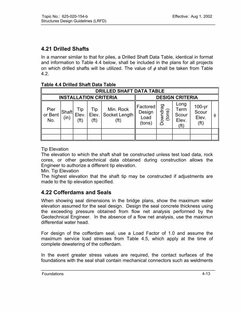
Topic No.: 625-020-154-b Effective: Aug 1, 2002 Structures Design Guidelines (LRFD)
Foundations 4-13
4.21 Drilled Shafts In a manner similar to that for piles, a Drilled Shaft Data Table, identical in format and information to Table 4.4 below, shall be included in the plans for all projects on which drilled shafts will be utilized. The value of φ shall be taken from Table 4.2.
Table 4.4 Drilled Shaft Data Table
DRILLED SHAFT DATA TABLE INSTALLATION CRITERIA DESIGN CRITERIA
Pier or Bent
No.
Shaft(in)
Tip Elev. (ft)
Tip Elev.(ft)
Min. Rock Socket Length
(ft)
FactoredDesign Load (tons) D
ownd
rag
(tons
)
Long Term Scour Elev. (ft)
100-yr Scour Elev. (ft)
φ
Tip Elevation The elevation to which the shaft shall be constructed unless test load data, rock cores, or other geotechnical data obtained during construction allows the Engineer to authorize a different tip elevation. Min. Tip Elevation The highest elevation that the shaft tip may be constructed if adjustments are made to the tip elevation specified.
4.22 Cofferdams and Seals When showing seal dimensions in the bridge plans, show the maximum water elevation assumed for the seal design. Design the seal concrete thickness using the exceeding pressure obtained from flow net analysis performed by the Geotechnical Engineer. In the absence of a flow net analysis, use the maximun differential water head. For design of the cofferdam seal, use a Load Factor of 1.0 and assume the maximum service load stresses from Table 4.5, which apply at the time of complete dewatering of the cofferdam. In the event greater stress values are required, the contact surfaces of the foundations with the seal shall contain mechanical connectors such as weldments
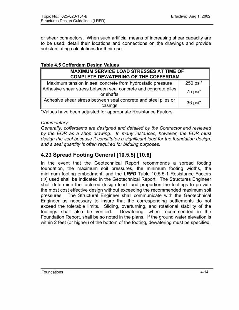
Topic No.: 625-020-154-b Effective: Aug 1, 2002 Structures Design Guidelines (LRFD)
Foundations
4-14
or shear connectors. When such artificial means of increasing shear capacity are to be used, detail their locations and connections on the drawings and provide substantiating calculations for their use. Table 4.5 Cofferdam Design Values
MAXIMUM SERVICE LOAD STRESSES AT TIME OF COMPLETE DEWATERING OF THE COFFERDAM
Maximum tension in seal concrete from hydrostatic pressure 250 psi* Adhesive shear stress between seal concrete and concrete piles
or shafts 75 psi*
Adhesive shear stress between seal concrete and steel piles or casings 36 psi*
*Values have been adjusted for appropriate Resistance Factors. Commentary: Generally, cofferdams are designed and detailed by the Contractor and reviewed by the EOR as a shop drawing. In many instances, however, the EOR must design the seal because it constitutes a significant load for the foundation design, and a seal quantity is often required for bidding purposes.
4.23 Spread Footing General [10.5.5] [10.6] In the event that the Geotechnical Report recommends a spread footing foundation, the maximum soil pressures, the minimum footing widths, the minimum footing embedment, and the LRFD Table 10.5.5-1 Resistance Factors (Ф) used shall be indicated in the Geotechnical Report. The Structures Engineer shall determine the factored design load and proportion the footings to provide the most cost effective design without exceeding the recommended maximum soil pressures. The Structural Engineer shall communicate with the Geotechnical Engineer as necessary to insure that the corresponding settlements do not exceed the tolerable limits. Sliding, overturning, and rotational stability of the footings shall also be verified. Dewatering, when recommended in the Foundation Report, shall be so noted in the plans. If the ground water elevation is within 2 feet (or higher) of the bottom of the footing, dewatering must be specified.
Topic No: 625-020-154-b Effective: Aug 1, 2002 Structures Design Guidelines (LRFD)
CHAPTER 5 SUBSTRUCTURE ELEMENTS
AND APPURTENANCES
5.1 General ...........................................................................................................1
5.2 Mass Concrete [5.10.8.3] ................................................................................1
5.3 Crack Control Requirements for Piers, Footings, and Walls ...........................1
5.4 Design Considerations in Piers, Columns, and Footings ................................2
5.5 Retaining Walls ...............................................................................................4 5.5.1 Wall Types (Site Applications) .....................................................................4 5.5.2 Design of MSE Walls ...................................................................................7
Substructure 5-i


Topic No: 625-020-154-b Effective: Aug 1, 2002 Structures Design Guidelines (LRFD)
SUBSTRUCTURE ELEMENTS AND APPURTENANCES
5.1 General This Chapter contains information and criteria related to the design, reinforcing, detailing, and construction of substructure elements and appurtenances and includes deviations from and supplementary requirements to LRFD criteria for substructure designs. In particular, this Chapter supplements LRFD Sections [5] and [11].
5.2 Mass Concrete [5.10.8.3] Consider Mass Concrete requirements in selecting member sizes and avoid Mass Concrete if practicable; however, when its use is unavoidable, indicate which portions are Mass Concrete. Mass Concrete is defined as: "Any large volume of cast-in-place or precast concrete with dimensions large enough to require that measures be taken to cope with the generation of heat and attendant volume change so as to minimize cracking." When the minimum dimension of the concrete exceeds 3 feet and the ratio of volume of concrete to the surface area is greater than 1.0 foot, provisions for mass concrete are required. (The surface area for this ratio includes the summation of all the surface areas of the concrete component being considered, including the full underside (bottom) surface of footings, caps, construction joints, etc.) Note Volume and surface area calculations in units of feet. Take precautionary measures to reduce the likelihood of cracking of the concrete. These precautionary measures are especially needed in the design of bascule bridge substructures and other structural components requiring the casting of large volumes of concrete. To prevent or control cracking in Mass Concrete, consider more and/or better reinforcing steel distribution, analyze the placement of construction joints, refer to other methods as outlined in ACI 207, ACI 244, and ACI 308. For estimated bridge pay item quantities, include separate pay item numbers for Mass Concrete (Substructure) and Mass Concrete (Superstructure). Do not calculate seal Concrete as Mass Concrete.
5.3 Crack Control Requirements for Piers, Footings, and Walls A. Long Walls:
For long walls and other similar construction:
Substructure 5-1
Topic No: 625-020-154-b Effective: Aug 1, 2002 Structures Design Guidelines (LRFD)
1.) Limit the length of a section to a maximum of 30 feet between vertical construction joints. See also the limits of concrete pours in tall piers elsewhere in this Chapter.
2.) Clearly detail required construction joints on the plans. 3.) Specify construction or expansion joints fitted with a water barrier when
necessary to prevent water leakage. B. Footings:
Specify that footings be cast monolithically. Attach struts and other large attachments as secondary castings.
C. Keyways: Do not place keyways in horizontal construction joints except that a keyway will be used at the junction of a cast-in-place concrete wall and footing. Provide keyways at formed surfaces of vertical construction joints and elsewhere as necessary to transfer applied loads from one cast section to an adjacent, second pour. Specify or detail trapezoidal keyways for ease of forming and stripping. For example, a typical joint must have a keyway about 2 inches deep and about 6 inches wide (or one third the thickness of the member for members less than 18 inches in thickness) running the full length.
5.4 Design Considerations in Piers, Columns, and Footings For tall piers or columns, detail construction joints to limit the concrete lifts to 25 feet. When approved by the Department, a maximum lift of 30 feet may be allowed to avoid successive small lifts (less than approximately 16 feet) which could result in vertical bar splice conflicts or unnecessary splice length penalties. Detail splices for vertical reinforcing at every horizontal construction joint; except that the splice requirement may be disregarded for any lift of 10 feet or less. Coordinate the lift heights and construction joint locations with the concrete placement requirements of the specifications. On structures over water, all vertical post-tensioning must be 12 feet above MHW. On structures over land, all vertical post-tensioning must be 5 feet above land (fill or natural ground). This restriction precludes the use of post-tensioning from the submerged substructure (fresh or salt) to an air dry condition within the substructure component. This applies to both CIP and/or precast substructures. Commentary: Precast pier segments traditionally have horizontal joints every 7’ to 10’ feet and at least 4 tendons vertically. Even with the highest attention to field inspection we find that many joints are not watertight. Water and chloride intrusion has been documented in superstructure and substructure post-tensioned tendons in Florida. The interstice area within the 7-wire strand and the space between strands offers too much opportunity for water and oxygen intrusion. Tendon geometry and duct placement (wobble) are factors that contribute to how much grout surround the
Substructure 5-2

Topic No: 625-020-154-b Effective: Aug 1, 2002 Structures Design Guidelines (LRFD) tendon bundle. During the forensic examinations of the corroded tendons it was observed that duct material must offer the primary protection for the strand material. Precast pier sections with spliced sleeve connections are allowed. Commentary: No problems have been reported with this type of rebar connections. Plant produced post-tensioned or pretensioned cylinder piles, horizontally assembled, stressed and grouted will be allowed due to the small tendon and duct size. The redundancy within the component due to the number of ducts with a maximum of 3 strands per duct has proved effective. When detailing precast, post-tensioned, segmented cylinder piles for use in pile bents, the void shall be filled with reinforced concrete to produce a redundant load path. The reinforced concrete plug shall extend from the cap to 2 feet below the MLW elevation, or ground line for land bents, regardless of the environmental classification, and far enough to fully develop the strength of the plug at the ground line or MLW elevation. The minimum wall thickness for segmental piers shall be 12 inches. Where external tendons exit the bottom of pier caps, provide a drip ½ by ½ “ drip recess around the tendon duct. For bridges designed for vessel collision, design pier columns solid from the footing to 15 feet above MHW. Provide solid section to base of pier columns (or fill with concrete) - Up to 12 feet above mean high water for water piers. - Up to 1 foot above finished ground level for land piers. Locate the bottom of all footings, excluding seals, a minimum of 1 foot below MLW. All hollow substructures shall be sealed from possible sources of leaks and shall contain free-exiting drains or weep-holes to drain away water that may collect from any source - including condensation. Drains in hollow piers may be formed using 2 inch diameter permanent plastic pipes set flush with the top of the bottom slab or solid section. Slope interior top of solid base toward drains or weep-holes. Provide weep-holes with vermin guards. Show in the Contract Drawings locations and details for drains taking into account bridge grade and cross-slope.
Substructure 5-3

Topic No: 625-020-154-b Effective: Aug 1, 2002 Structures Design Guidelines (LRFD) Table 5.1 Required tendons for post-tensioned substructure elements:
Post-Tensioned Bridge Element Minimum Number of Elements Hammerhead Pier Straddle Beams
C-Pier Column (Bars Only) C-Pier Cap
C-Pier Footings (Bars only)
6
Hollow cast Piers I-Section Piers 8
5.5 Retaining Walls Retaining wall plans preparation and administrative requirements are included in Chapter 30 of the Plans Preparation Manual which must be used in conjunction with the design requirements of this Section. Refer to Chapter 2 for the retaining wall concrete class and reinforcing steel cover requirements. Show the retaining wall concrete class on the plans. 5.5.1 Wall Types (Site Applications) Consider site, economics, aesthetics, maintenance and constructability when determining the appropriate wall type. The following wall types are being used or considered for use by FDOT. A. Conventional Cast-in-Place (CIP) Walls:
CIP walls are normally used in either a cut or fill situation. These walls are sensitive to foundation problems. The foundation soil must be capable of withstanding the design bearing pressure and must exhibit very little differential settlement. Verify that during the life of the structure the bearing capacity of the soil will not be diminished (i.e., french drains in close proximity to the walls) thus requiring pile supported walls. This type of wall has an advantage over MSE walls because they can be built with conventional construction methods even in Extremely Aggressive Environments. Another advantage over MSE walls is on cut/widening projects where the area behind the wall is not sufficient for soil reinforcement (See Figures 5-2 and 5-3).
The relative cost of CIP walls is greater than MSE walls when the site and environment are appropriate for each wall type. This is assuming the area of wall is greater than 1000 sq ft and greater than 10 feet in height.
B. Pile Supported Walls: Pile supported walls are utilized when the foundation soil is not capable of supporting the retaining wall and associated dead and live loads on a spread footing.
Substructure 5-4

Topic No: 625-020-154-b Effective: Aug 1, 2002 Structures Design Guidelines (LRFD)
Pile supported retaining walls are extremely expensive compared to CIP cantilevered and MSE walls and are only appropriate when foundation soil conditions are not conducive for CIP or MSE walls. Pile supported walls are appropriate for cut or fill sites. Temporary sheeting may be required in cut sites (See Figures 5-4 and 5-5).
C. Mechanically Stabilized Earth (MSE) Walls: MSE walls are not a cure-all for poor foundation soil and are not appropriate for all sites. MSE walls are very adaptable to both cut and fill conditions and will tolerate a greater degree of differential settlement than CIP walls. Because of their adaptability MSE walls are being used almost exclusively. The design of MSE walls with metallic reinforcement, however, is sensitive to the electrochemical properties of the backfill material and to the possibility of a change in the properties of the backfill materials due to submergence in water classified as Extremely Aggressive or from heavy fertilization. Consider using geosynthetic reinforcement in areas where the water is classified as an Extremely Aggressive Environment when the 100-year flood can infiltrate the backfill, and when the wall is within 12 feet of the Mean High Water (MHW). MSE walls are generally the most economical of all wall types when the area of retaining wall is greater than 1000 sq ft, and the wall is greater than 10 feet in height (See Figures 5-6 and 5-7).
D. Precast Counterfort Walls: Precast counterfort walls are applicable in cut or fill locations. Their advantage is in cut locations such as removing front slopes under existing bridges and in certain widening applications where sheet piling would be required to stabilize excavation for earth reinforcements for MSE walls. Also, their speed of construction is advantageous in congested areas where maintenance of traffic is a problem. This type of wall is also applicable in areas where the backfill is or can become classified as extremely corrosive.
This type of wall is generally not as economical as MSE walls but is competitive with CIP walls (See Figure 5-8) and may offer aesthetic and constructability advantages.
E. Steel Sheet Pile Walls (Permanent and Temporary): Steel sheet pile walls are applicable for use in permanent locations (i.e., bulkheads) but their more common use is for temporary use (i.e., phase construction). Generally steel sheet pile walls can be designed as cantilevered walls up to approximately 15 feet in height. Steel sheet pile walls over 15 feet are tied back with either prestressed soil anchors, soil nails, or deadmen.
Steel sheet pile walls are relatively expensive initially and require periodic maintenance (i.e. painting, cathodic protection). This type of wall should only be used if there are no other more economical alternates (See Figure 5-9).
Substructure 5-5
Topic No: 625-020-154-b Effective: Aug 1, 2002 Structures Design Guidelines (LRFD)
Refer to Chapter 8 for design criteria.
F. Concrete Sheet Piles: Concrete sheet piles are primarily used as bulkheads in either fresh or saltwater. Rock in close proximity to the ground surface is a concern with this type of wall as they are normally installed by jetting. Concrete sheet piles when used as bulkheads are normally tied back with deadmen.
This type of wall is relatively costly and should only be used when less costly alternates are not appropriate or when the environment is appropriate (See Figure 5-10).
G. Wire Faced Walls: Wire faced walls are applicable in temporary situations, phase construction where large amounts of settlement are anticipated or where surcharges are required to accelerate settlement. This type of wall is a form of MSE wall. The soil reinforcement may be either steel or geogrid. Verify that proposed systems have been pre-approved. Pre-approved companies have their standard details in the Roadway and Traffic Design Standards or on the Structures Design Office’s Internet Homepage (See Figure 5-11).
H. Soil Nails: The Department is allowing the use of soil nails. The relative cost of this type wall has not been determined because Contractors have yet to bid this alternate (See Figure 5-12).
I. Soldier Pile/Panel Walls: This type of wall is applicable in bulkheads and retaining walls where the environment is Extremely Aggressive and/or rock is relatively close to the ground surface. The cost of this type of wall is very competitive with concrete sheet pile walls (See Figure 5-13).
J. Modular Block Walls: Modular blocks consist of drycast, unreinforced blocks which are sometimes used as a gravity wall and sometimes used as a wall facing for a MSE variation normally utilizing a geogrid for soil reinforcement. The Department is considering systems of this type for low-height, non-structural applications only.
K. Geogrid Soil Reinforcement for Retaining Walls: Geogrids are presently approved for use in temporary and select (Extremely Aggressive Environments) permanent walls only. Their use in permanent walls is being reviewed. Some of the concerns about geogrids are the long term stress-strain characteristics of polymers, hydrolysis of polyesters, environmental stress cracking, and brittle rupture of polyolefins (high density polyethylene, polyethelene and polypropylene) and appropriate factors to ensure an allowable stress condition at the end of the structure's service life.
Substructure 5-6
Topic No: 625-020-154-b Effective: Aug 1, 2002 Structures Design Guidelines (LRFD)
L. Permanent - Temporary Wall Combination:
As more highways are widened, problems have been encountered at existing grade separation structures. The existing front slope at the existing bridge must be removed to accommodate a new lane and a retaining wall must be built under the bridge. Several methods have been used to remove the existing front slope and maintain the stability of the remaining soil. One method is to excavate slots or pits in the existing fill to accommodate soldier beams. The soil is then excavated and timber lagging is placed horizontally between the vertical soldier beams. The soldier beams are tied-back by the use of prestressed soil anchors. This procedure will maintain the soil while the permanent wall is built. The permanent wall should be designed to accept all appropriate soil, dead and live loads. The temporary lagging shall not contribute to the strength of the permanent wall (See Figure 5-3).
M. Hybrid - Gravity/MSE Wall: Hybrids are basically gravity systems with some MSE characteristics. The FDOT approved system has a concrete stem that extends into the fill a sufficient length to satisfy the external stability requirement for the wall. However, due to its rigid stem, the system is sensitive to both longitudinal and transverse settlement. This system can be used in cut and/or fill applications (See Figure 5-15)
N. Earth Loads for Wall Design In lieu of lateral earth loads on walls developed from a Coulomb earth pressure, the Rankine earth pressure may be used. If the Rankine earth pressure is used, the resultant lateral earth load can be assumed to be located at the centroid of the earth pressure diagram.
5.5.2 Design of MSE Walls A. Corrosion Rates:
Delete the corrosion rates specified in LRFD Article [11.9.8.1] and substitute in lieu thereof the following requirements:
The following corrosion rates for metallic reinforcement apply to non-corrosive (Slightly or Moderately Aggressive) Environments only: 1.) Zinc (first 2 years).....................................................................15 microns/year 2.) Zinc (subsequent years to depletion) .........................................4 microns/year 3.) Carbon Steel (after depletion of zinc) .......................................12 microns/year 4.) Carbon Steel (75 to 100 years) ..................................................7 microns/year
Do not use Metallic reinforcement in Extremely Aggressive Environments without approval from the State Structures Design Engineer.
Substructure 5-7
Topic No: 625-020-154-b Effective: Aug 1, 2002 Structures Design Guidelines (LRFD) B. Soil Reinforcement:
1.) Design soil reinforcement and connections for permanent walls with a design life of 75 years. Design walls supporting abutments on spread footings with a design life of 100 years.
2.) Design soil reinforcement for temporary walls with a design life of not less than the contract time of the project or three years whichever is greater.
3.) Verify the stress in the steel soil reinforcement will not exceed 0.55Fy for steel straps, and 0.48Fy for welded wire mats or grids. Specify ASTM A82, Grade 60 steel.
4.) Analyze vertical stresses at each reinforcement level for local equilibrium of all forces to that level only. Include the effects of any eccentricity.
5.) Specify galvanized steel soil reinforcement for permanent walls. galvanized. Steel soil reinforcement for temporary walls may be galvanized or uncoated (black) steel.
6.) Epoxy coated reinforcement as specified in LRFD [11.9.8.1] is not permitted. Passive metal soil reinforcement (i.e., stainless steel, aluminum alloys, etc.) is permitted for use only with written approval of the SDO.
7.) Geosynthetic Geogrids must comply with Chapter 31 of the Plans Preparation Manual, Volume I (Topic No. 625-000-005).
8.) Do not design Soil reinforcement skewed more than 15 degrees from a position normal to the wall panel unless necessary and clearly detailed for acute corners.
9.) In addition to LRFD Article [11.9.5.1.4], soil reinforcement lengths, “L”, measured from the back of the facing element, shall not be less than the greater of the following:
MSE Walls and Walls in Front of Abutments on Piling [11.9.5.1.4] L = 8 feet minimum length. L = 0.7 H1, H1 = mechanical height of wall, in feet (See Figures 5-16 and 5-17) L = length in feet, required for external stability design. MSE Walls In Front of Abutments on Spread Footings [11.9.7] L = 22 feet L = 0.6 H1 + 6 feet L = 0.7 H1
Commentary: As a rule of thumb, for an MSE structure with reinforcement lengths equal to 70% of mechanical height, the anticipated maximum calculated bearing pressure can be anticipated to be about 135% of the overburden weight of soil and surcharge. It may be necessary to increase the reinforcement length for external stability to assure that the allowable bearing pressure specified equals or exceeds this value.
Substructure 5-8

Topic No: 625-020-154-b Effective: Aug 1, 2002 Structures Design Guidelines (LRFD)
10.) External Stability: The required factors of safety for the external stability are as follows: Overturning ............................................................................................... 2.0 Sliding........................................................................................................1.5 Internal Pullout......................................... 1.5 (Allowable deformation ¾ inch) Bearing Capacity .......................................................................................2.5 Overall Stability..........................................................................................1.5 The reinforced backfill soil parameters for the analyses are: Sand fill (statewide except Dade and Monroe counties) Moist unit weight......................................................................... 105 pcf min. Friction angle............................................................................... 30 degrees. Limerock fill (Dade and Monroe counties only) Moist unit weight................................................................................ 115 pcf Friction angle...............................................................................34 degrees For steel reinforcements, consider the following requirements: For Bars and Straps Fy
’ ...................................................................... 0.55 Fy at end of design life. Fu ............................................... 0.55 Fu at net section of bolted connection For Grids and bar mats Fy
’ .......................................................................................................0.48 Fy Maximum pullout factors: f* max ................................................................................ 1.5 for ribbed strips Npmax ....................................................................... 30 for grids and bar mats For geogrids, the properties can be found in the Index 501 of the Roadway and Traffic Standards (January 2000, English Units.) H1, the mechanical height, of an MSE structure shall be taken as the height measured to the point where the potential failure plane (line of maximum tension) intersects the ground surface, as shown in Figure 5-16 and 5-17 and can be calculated using the equation provided in Figure 5-16. The methodology for this analysis is included in FHWA publication FHWA-SA-96-072 Mechanically Stabilized Earth Walls and Reinforced Soil Slopes Design and Construction Guideline In addition to the two conditions shown in AASHTO, horizontal backslope and infinite sloping backfill, we are including Figures 5-16 and 5-17 to illustrate broken back slope conditions with and without traffic surcharge. If the break in the slope behind the wall facing is located within two times the height of the wall (2H), then the broken back slope design shall apply. If a traffic surcharge is present and is located within 0.5H of the back of the reinforced soil mass, then it shall be included in the analysis.
Substructure 5-9
Topic No: 625-020-154-b Effective: Aug 1, 2002 Structures Design Guidelines (LRFD)
The Geotechnical Engineer of Record for the project is responsible for designing the strap lengths for the external conditions shown in Figure 5-1 and any other conditions that are appropriate for the site.
11.) Acute corners less than 75 degrees (MSE Walls):
When two walls intersect forming an internal angle of less than 75 degrees, design the nose section as a bin wall. Submit the calculations for this special design with the plans for review and approval. Design structural connections between the wall elements within the nose section to create an at-rest bin effect without eliminating the flexibility of the facing to tolerate differential settlements. The design for connections to facing elements and allowable stresses in the connecting members shall conform to the requirements for the wall design in general. Design the nose section to settle differentially from the remainder of the structure with a slip joint. Facing panel overlap or interlock or rigid connection across that joint is not permitted. Design soil reinforcements to restrain the nose section by connecting directly to each of the facing elements in the nose section and running back into the backfill of the main reinforced soil mass at least to a plane 10 feet beyond a Rankine failure surface. Design for facing connections, obstructions, pullout and allowable stresses in the reinforcing elements shall conform to the requirements of the wall design in general (See Figure 5-18).
12.) Minimum Wall embedment in the soil: Consideration scour and bearing capacity when determing wall embedment depth. Consult the District Drainage and Geotechnical Engineers to determinine the elevation of the top of leveling pad which must also conform to a minimum embedment to the top of leveling pad of 1’-6” as determined in Figure 5-19.
13.) Apparent Coefficient of Friction (f*): The coefficient of friction (f*) need not be reduced for backfills that are saturated and are properly placed and compacted.
14.) Connections (MSE Walls): Design the soil reinforcement to facing panel connection to assure full contact. Normally mesh and bar mats are connected to the facing panel by a pin passing through loops at the end of the reinforcement and loops inserted into the panels. If these loops are not aligned, then some reinforcement will not be in contact with the pins causing the remaining reinforcement to be unevenly stressed and/or over stressed. If the quality of this connection cannot be assured then the allowable stress in the soil reinforcement and its connections should be reduced accordingly.
Substructure 5-10

Topic No: 625-020-154-b Effective: Aug 1, 2002 Structures Design Guidelines (LRFD)
15.) End Bents Behind MSE Walls: a.) End Bents on Piling:
i.) All end bent piles must be plumb. ii.) The front face of the end bent cap or footing shall be a minimum distance
of 2 feet behind the front face of the wall. (2 feet minimum clear distance between face of piling and leveling pad). This dimension is based upon the use of 18 inch piles. For larger piles, the clear distance between the wall and pile shall be increased such that no strap is skewed more than 15 degrees.
iii.) Soil reinforcement to resist the overturning produced by the earth load, friction, and temperature shall be attached to end bents. If the long-term settlement exceeds 4 inches, the reinforcement shall not be attached to the end bent. In this event, a special wall behind the backwall shall be designed to accommodate the earth load.
b.) End Bents on Spread Footings: i.) The spread footing shall be sized so that the bearing pressure shall not
exceed 3000 psf. ii.) The footing shall be a minimum distance of 1 foot behind the facing
panel. iii.) The minimum distance between the centerline of bearing on the end
bent and the back of the facing panel shall be 4 feet. 16.) Facing Panels (MSE Walls) [11.9.5.1.6]:
a.) The basic (typical) panel size shall not exceed 40 sq ft in area, and special panels (top out, etc.) shall not exceed 50 sq ft in area. Full-height facing panels shall not exceed 8 feet in height. Use of larger panels will be considered by the SDO on a case-by-case basis. The reinforcing steel concrete cover shall comply with Table 2.2.
17.) Soil reinforcement shall not be attached to piling, and abutment piles shall not be attached to any retaining wall system.
18.) The horizontal soil reinforcement connection force of 85% of the maximum calculated force as stated in LRFD Article [11.5.1.2] shall be modified to a minimum of 100% Tmax, where:
Tmax = Ta (maximum stress in soil reinforcement) 19.) Creep reduction factors in geosynthetic soil reinforcement shall be included
in seismic designs. 20.) In addition to LRFD Article [11.9.4.3] for overturning, the following shall also
apply: a.) Use a soil resistance factor of 0.67 for overturning.
Polymeric Reinforcements in Soils, LRFD Article [11.9.5.1.3] shall be supplemented with the following: For geosynthetics, Ta shall not exceed the following values:
a.) Ta = 17% Tult for permanent walls and critical temporary walls. b.) Ta = 29% Tult for temporary walls. c.) Minimum Front Face Embedment:
The minimum front face embedment shall comply with Figure 5-19.
Substructure 5-11

Topic No: 625-020-154-b Effective: Aug 1, 2002 Structures Design Guidelines (LRFD)
d.) Utilities: No utilities should be allowed in the soil reinforced zone behind MSE or
tied-back walls. Commentary: When utilities are placed in the reinforced zone, they cannot be maintained because excavation in this zone will compromise the structural integrity of these types of walls. Furthermore, pipes carrying fluids, if cracked or broken, could also wash out and destroy the structural integrity of the wall.
Substructure 5-12

Topic No: 625-020-154-b Effective: Aug 1, 2002 Structures Design Guidelines (LRFD)
Figure 5-1
Substructure 5-13

Topic No: 625-020-154-b Effective: Aug 1, 2002 Structures Design Guidelines (LRFD)
Figure 5-2
Substructure 5-14
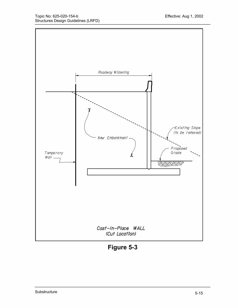
Topic No: 625-020-154-b Effective: Aug 1, 2002 Structures Design Guidelines (LRFD)
Figure 5-3
Substructure 5-15
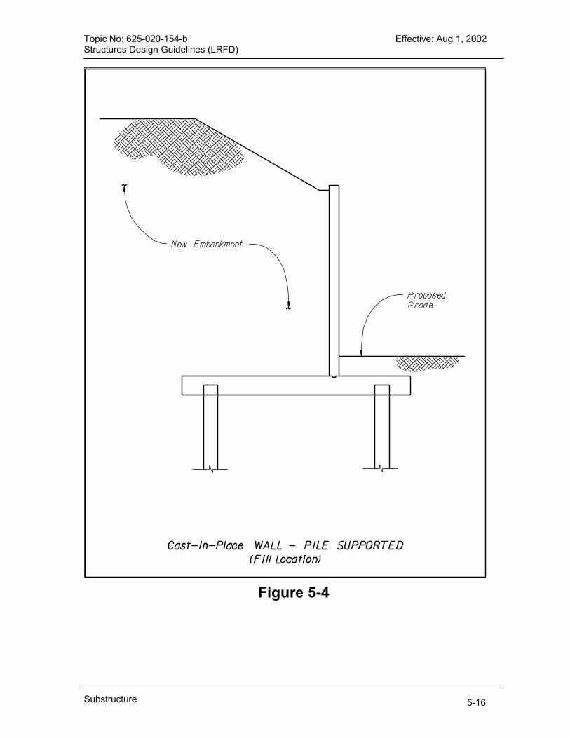
Topic No: 625-020-154-b Effective: Aug 1, 2002 Structures Design Guidelines (LRFD)
Figure 5-4
Substructure 5-16
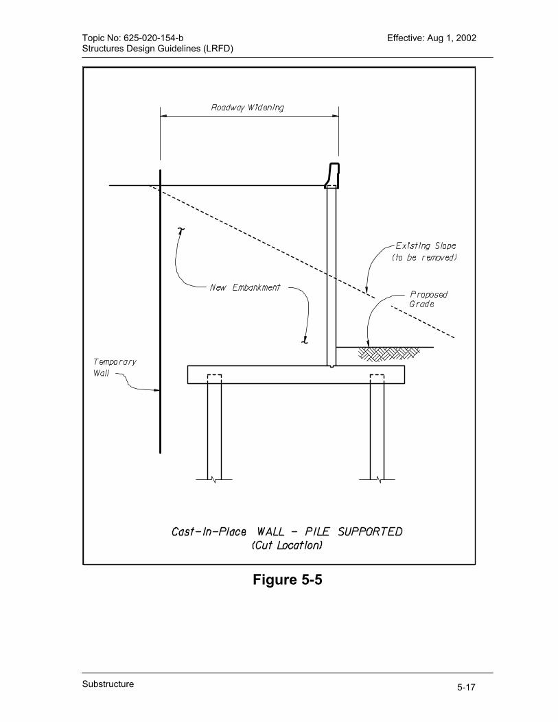
Topic No: 625-020-154-b Effective: Aug 1, 2002 Structures Design Guidelines (LRFD)
Figure 5-5
Substructure 5-17

Topic No: 625-020-154-b Effective: Aug 1, 2002 Structures Design Guidelines (LRFD)
Figure 5-6
Substructure 5-18

Topic No: 625-020-154-b Effective: Aug 1, 2002 Structures Design Guidelines (LRFD)
Figure 5-7
Substructure 5-19
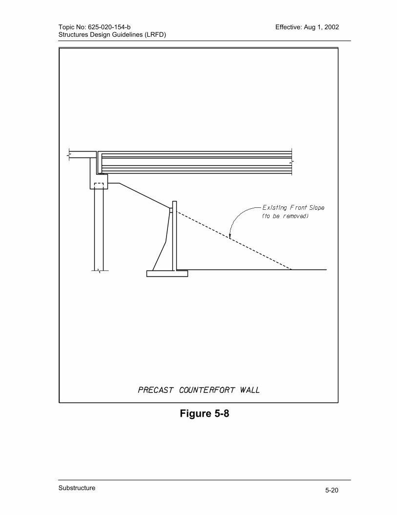
Topic No: 625-020-154-b Effective: Aug 1, 2002 Structures Design Guidelines (LRFD)
Figure 5-8
Substructure 5-20

Topic No: 625-020-154-b Effective: Aug 1, 2002 Structures Design Guidelines (LRFD)
Figure 5-9
Substructure 5-21

Topic No: 625-020-154-b Effective: Aug 1, 2002 Structures Design Guidelines (LRFD)
Figure 5-10
Substructure 5-22
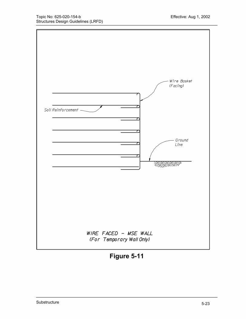
Topic No: 625-020-154-b Effective: Aug 1, 2002 Structures Design Guidelines (LRFD)
Figure 5-11
Substructure 5-23

Topic No: 625-020-154-b Effective: Aug 1, 2002 Structures Design Guidelines (LRFD)
Figure 5-12
Substructure 5-24
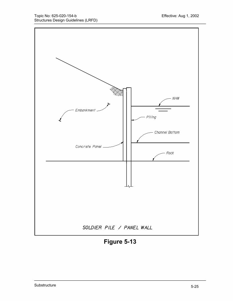
Topic No: 625-020-154-b Effective: Aug 1, 2002 Structures Design Guidelines (LRFD)
Figure 5-13
Substructure 5-25

Topic No: 625-020-154-b Effective: Aug 1, 2002 Structures Design Guidelines (LRFD)
Figure 5-14
Substructure 5-26
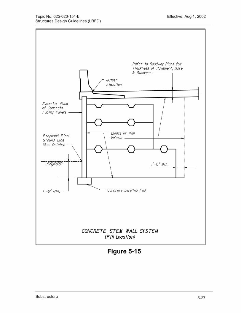
Topic No: 625-020-154-b Effective: Aug 1, 2002 Structures Design Guidelines (LRFD)
Figure 5-15
Substructure 5-27

Topic No: 625-020-154-b Effective: Aug 1, 2002 Structures Design Guidelines (LRFD)
Figure 5-16
Substructure 5-28

Topic No: 625-020-154-b Effective: Aug 1, 2002 Structures Design Guidelines (LRFD)
Figure 5-17
Substructure 5-29
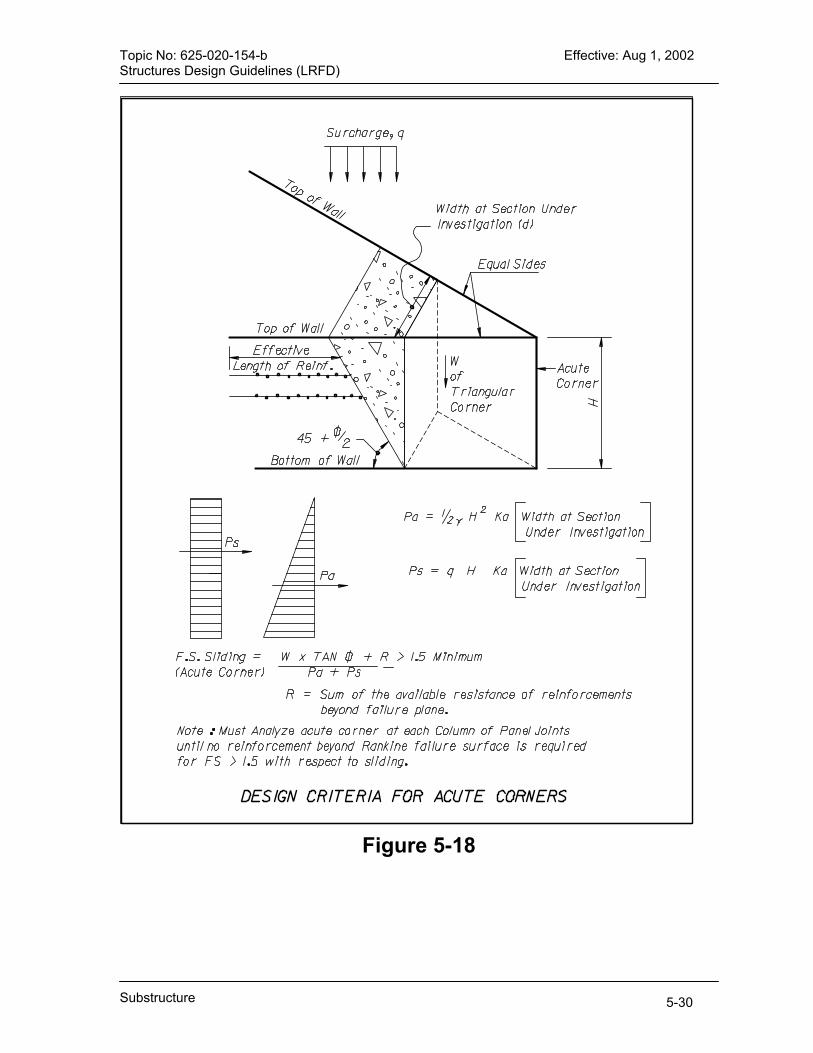
Topic No: 625-020-154-b Effective: Aug 1, 2002 Structures Design Guidelines (LRFD)
Figure 5-18
Substructure 5-30
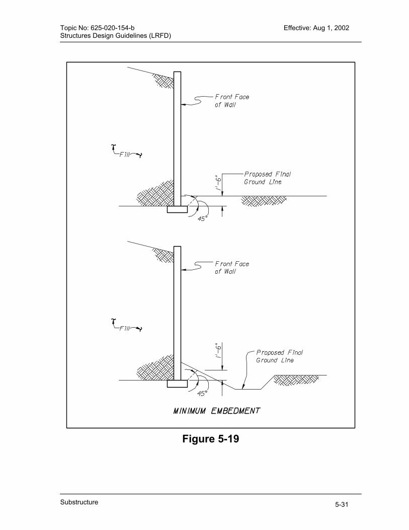
Topic No: 625-020-154-b Effective: Aug 1, 2002 Structures Design Guidelines (LRFD)
Substructure 5-31
Figure 5-19

Topic No.: 625-020-154-b Effective: Aug 1, 2002 Structures Design Guidelines (LRFD)
CHAPTER 6 SUPERSTRUCTURE ELEMENTS
AND APPURTENANCES
6.1 General ........................................................................................................6-1
6.2 Curb and Median Heights on Bridges [13.11] ..............................................6-1 6.3 Deck Drainage Systems [2.6.6]....................................................................6-1
6.3.1 Deck Drains............................................................................................6-1 6.3.2 Drain Conveyances ................................................................................6-1
6.4 Traffic Railing Barriers [13.7]........................................................................6-2 6.4.1 General Requirements ...........................................................................6-2 6.4.2 Existing Bridges with Sub-Standard Traffic Railing Barriers...................6-2 6.4.3 Traffic Railing Barriers for Historic Bridges.............................................6-2 6.4.4 Requirements for Test Levels TL-5A, TL-5 and TL-6 [13.7.2] ................6-3 6.4.5 Exceptions..............................................................................................6-3
6.5 General Policy for Joint Devices ..................................................................6-3 6.6 General Policy for Bridge Bearings ..............................................................6-4 6.7 Movement Due to Temperature Variation [3.12.2] .......................................6-4 6.8 Expansion Joint Provisions [14.5.1] .............................................................6-5 6.9 Design of Expansion Joints to Accommodate Movement [14.4] [14.5.3] .....6-6 6.10 Joints for Bridge Widening .........................................................................6-6
6.10.1 Lengthening of Group 1 Joints .............................................................6-6 6.10.2 Widening of Bridges with Group 2 Joints..............................................6-7
6.11 Design of Bearings.....................................................................................6-7 6.12 Maintainability Requirements – Bearings...................................................6-8 6.13 Control of Shrinkage Cracking in Continuous Superstructures [5.10.8] .....6-8 6.14 Lateral Restraint of Superstructures ..........................................................6-9
6.14.1 Elastomeric Bearings ...........................................................................6-9 6.14.2 Mechanically Restrained Bearings .......................................................6-9
6.15 Girder Transportation.................................................................................6-9
Superstructure
6-i


Topic No.: 625-020-154-b Effective: Aug 1, 2002 Structures Design Guidelines (LRFD)
CHAPTER 6
SUPERSTRUCTURE ELEMENTS AND APPURTENANCES
6.1 General
This Chapter contains information and criteria related to the design, reinforcing, detailing, and construction of superstructure elements and appurtenances for bridge structures and includes deviations from LRFD that are required for these same elements and appurtenances. The Chapter includes elements that are part of the superstructure such as deck slabs, beams, barriers, curbs, and pilasters as well as appurtenances that are essential accessories to the superstructure such as joints, bearings, and deck drains.
6.2 Curb and Median Heights on Bridges [13.11] For bridge projects that utilize curbs, the curb height and batter shall match the curb height and batter on the roadway approaches. Bridges with sidewalks are normally encountered in an urban environment, and the curb will normally be 6 inches in height. When the roadway approaches the bridge with a raised median, the median on the bridge shall match that on the roadway.
6.3 Deck Drainage Systems [2.6.6]
6.3.1 Deck Drains
For simple deck drains (i.e. scuppers) encased in concrete, specify schedule 80, UV-resistant Polyvinyl-Chloride (PVC), gray cast iron, or ductile cast iron. For other deck drains encased in concrete, such as grates and inlets, specify Gray Cast Iron, Ductile Cast Iron, or Galvanized Steel. Do not specify Gray Cast Iron or Ductile Cast Iron for use in Extremely Aggressive Environments. The maximum width of a grate slot is one and one-half (1½ ) inches.
6.3.2 Drain Conveyances
For drain conveyances encased in concrete, specify Polyethylene (PE), or Ductile Cast Iron. For drain conveyances not encased in concrete, speicfy machine-made or filament-wound “Fiberglass” (Glass-Fiber-Reinforced-Thermosetting-Resin), or Ductile Cast Iron. Do not specify ductile cast iron in Extremely Aggressive Environments. Do not specify pipe diameters less than 4 inches, or bends greater than 45o.
Superstructure
6-1

Topic No.: 625-020-154-b Effective: Aug 1, 2002 Structures Design Guidelines (LRFD) 6.4 Traffic Railing Barriers [13.7]
Unless otherwise approved, all new traffic railing barriers proposed for use in new construction, rehabilitation, reconstruction, and widening projects, as well as all traffic railing barrier systems proposed as a retrofit for existing traffic railing barriers, shall be proven effective through successful crash testing. Crash testing shall be performed in accordance with, and comply with, the National Cooperative Highway Research Program (NCHRP) Report No. 350 and LRFD. This requirement also applies to barrier and sound wall combinations. The traffic railing barriers shown on the Standard Drawings have been determined to meet the applicable crash testing requirements. Sound barrier walls shall not be attached to the top of railing barriers unless the system has been crach tested and meets TL-4 acceptability requirements of NCHRP Report No. 350. Sound barrier walls may be attached to structures if located behind an approved traffic railing barrier and mounted at least five feet from the face of the barrier at deck level.
6.4.1 General Requirements
In addition to the preceding criteria, all traffic railing barriers shall: A. Be structurally evaluated to be equivalent to or greater in strength to other safety
shape railings that have been crash tested to the TL-4 criteria of NCHRP Report No. 350.
B. Meet the strength and geometric requirements of LRFD Chapter 13 in accordance with the test levels and crash test criteria.
C. Be upgraded on both sides of a structure when widening work is proposed for only one side and the traffic rail barrier on the non-widened side does not meet the criteria for new traffic rail barriers.
D. Be constructed on decks reinforced in accordance with Chapter 7.
6.4.2 Existing Bridges with Sub-Standard Traffic Railing Barriers
When rehabilitation or renovation work is proposed on an existing structure with traffic railing barriers that do not meet the criteria for new railing barriers as provided above, the existing traffic railing barriers shall be replaced or retrofitted to meet the crash-worthy criteria unless an exception is approved. Unless otherwise approved by DSDE or SSDE, the traffic railing barriers and portions of the bridge deck to which they are anchored shall meet the “General Requirements” of this article.
6.4.3 Traffic Railing Barriers for Historic Bridges
With respect to historic bridge sites and areas of great aesthetic concern, case-by-case evaluation to the crash-worthy criteria will be considered within the following limits: Superstructure
6-2

Topic No.: 625-020-154-b Effective: Aug 1, 2002 Structures Design Guidelines (LRFD) A. An exception request shall include written justification explaining the special
historic or aesthetic concerns at the site, and why a crash-worthy traffic railing barrier is not compatible.
B. Design speed and operating speed shall be no greater than 40 mph. C. The strength requirements stated in “General Requirements” above are met.
6.4.4 Requirements for Test Levels TL-5A, TL-5 and TL-6 [13.7.2]
Consideration should be given to providing a traffic railing barrier that meets the requirements of Test Levels TL-5A, TL-5 and TL-6 as included in NCHRP Report No. 350 when any of the following conditions exist: A. The volume of truck traffic is unusually high. B. The proposed structure is located such that a vehicle penetrating the railing
barrier would cause high risk to the public or surrounding facilities. C. Sharply curved ramp structures with moderate to heavy truck traffic.
6.4.5 Exceptions
Exceptions to the requirements of this Article shall be approved in accordance with Chapter 23 of the Plans Preparation Manual, Volume I with concurrence of the DSDE or SSDE as appropriate.
6.5 General Policy for Joint Devices
Minimize the use of joints. Bridge deck joints are a continuous minor maintenance problem and may be a source of structural deterioration resulting in a major bridge maintenance problem. Expansion joints in bridge decks can be avoided by providing deck slab continuity at intermediate bents or piers. Generally, this is accomplished by designing continuous superstructures, or by allowing continuity of the deck slab, even when the supporting beams or girders are simply supported. In either case, the structures must be designed to accommodate the movements, or to resist the stresses, due to factors such as: temperature, elastic shortening, creep, and shrinkage. For “Long Bridges” (see Chapter 7,) detail expansion joints for installation as an independent operation performed after deck planing requirements have been met. For new construction use only joint types listed in Table 6.1. The values in Table 6.1 are maximum design values for each joint type. Specify silicone seals for all cast-in-place, flat slab bridges. Limit the continuous unit lengths to accommodate the allowable movement listed in Table 6-1.
Superstructure
6-3

Topic No.: 625-020-154-b Effective: Aug 1, 2002 Structures Design Guidelines (LRFD) Table 6.1 Joint Width Limitations by Joint Type
Joint Type Maximum Joint Width*
Poured Rubber ¾”
Silicone Seal 2”
Strip Seal 3”
Modular Joint Unlimited
Finger Joint Unlimited
*Joints in sidewalks must meet all requirements of Americans with Disabilities Act.
6.6 General Policy for Bridge Bearings
Bridge bearings must accommodate the movements of the superstructure and transmit loads to the substructure supports. The type of bearings to be used depends upon the amount and type of movement as well as the magnitude of the load. In general, simple-span, prestressed concrete beams, simple-span steel girders, and some continuous beams can be supported on composite neoprene bearing pads (elastomeric bearings). Larger longitudinal movements can be accommodated by using PTFE polytetrafluoroethylene [Teflon] bearing surfaces on external steel load plates Some structures with large bearing loads and/or multi-directional movement might require other bearing devices such as pot, spherical, or disc bearings.
6.7 Movement Due to Temperature Variation [3.12.2]
For all bridges other than longitudinally post-tensioned, segmental concrete bridges, calculate movement due to temperature variation (range) with an assumed mean temperature of 70 degrees Fahrenheit (°F) at the time of construction. Base joint and bearing design on the expansion and contraction for temperature ranges of Table 6.2.
Superstructure
6-4

Topic No.: 625-020-154-b Effective: Aug 1, 2002 Structures Design Guidelines (LRFD) Table 6.2 Temperature Range by Superstructure Type
Temperature (Degrees Fahrenheit) Structural Material
of Superstructure Mean High Low Range
Concrete Only 70 95 45 50 Concrete Deck on Steel Girder 70 110 30 80
Steel Only 70 120 30 90 The thermal coefficients of LRFD [5.4.2.2] and [6.4.1] for normal density concrete and structural steel, respectively, apply to the material of the main longitudinal supporting beams or girders.
6.8 Expansion Joint Provisions [14.5.1]
A. When an expansion joint is required, the joint design shall satisfy the following criteria as applicable:
1.) Proprietary joint device must be designed in accordance with LRFD and installed in strict comformance with the manufacturer's specifications unless directed otherwise by the Department.
2.) Ensure that joint components will accommodate the full range of structure movement without exceeding the manufacturer's limitations and/or design values, particularly at maximum joint opening.
3.) The joint must provide a good riding surface, relatively free from vibration and noise.
4.) Design frame rails to resist all anticipated loads, including impact 5.) The joint shall not transfer undue stresses to the structure. 6.) Specify joint seal elastomers with a minimum five year service life. 7.) Design the joint for minimum maintenance and ease of access and parts
replacement. 8.) Design a reasonably leak-proof joint with a continuous sealing element for the
entire joint length. 9.) Specify that the joint material be resistant to corrosion and ultraviolet rays and
is not a catalyst or vehicle for electrolytic action. B. In some instances, open joints may be acceptable; however such joints must
have provision for diverting drainage without causing damage to the bridge bearings or other structural elements and must have the prior approval of the SDO.
Superstructure
6-5
Topic No.: 625-020-154-b Effective: Aug 1, 2002 Structures Design Guidelines (LRFD) 6.9 Design of Expansion Joints to Accommodate Movement [14.4]
[14.5.3]
When designing expansion joints, analyze movement due to temperature variation, the effects of creep, shrinkage, skew, rotation, lateral shear, and vertical shear. Design conventional, reinforced and/or prestressed concrete superstructure joints for the calculated movement due to temperature change plus creep and shrinkage, or for 115% of the calculated movement due to temperature change alone, however, the joint opening must not be less than 5/8 inch at 70 degrees Fahrenheit (°F). Design longitudinally post-tensioned, superstructure joints for creep and shrinkage plus 120% of the calculated movement due to temperature change. The width, “W”, of the joint shall meet the requirements of LRFD [14.5.3.2], except that “W” for the different joint types shall not exceed the appropriate value from Table 6.1. When setting the joint, either the design width, “W,” shall be decreased by the amount of anticipated movement due to creep and shrinkage, or the joint shall be set to the minimum width for installing the joint, whichever results in the wider opening.
6.10 Joints for Bridge Widening
A. Contact the District Structures and Facilities Office to determine the type and condition of all existing joints to be widened. Existing joint types by group are:
1.) Group 1: Strip seal, compression seal, poured rubber, open joint, silicone seal, copper water-stop, and “Jeene.”
2.) Group 2: Sliding Plate, finger joint, and modular. B. Existing joints to be widened shall be carefully examined to determine in advance
the extent of existing concrete deck to be removed. Removal of existing concrete shall be limited to that necessary to remove the existing joint armor and to permit proper anchorage of the new joint armor. Detail the existing joint removal, and/or note that extreme care shall be taken by the Contractor, to assure that the existing deck reinforcing steel will not be damaged by the new joint installation.
6.10.1 Lengthening of Group 1 Joints
A. If the existing joint consists of armored strip seal and the steel armor is in good condition, remove the existing seal, extend the armor into the widening by welding new sections to existing armor and provide new strip seal continuously across the entire deck.
B. If an existing armored joint is in poor and irreparable condition, or if the existing joint system consists of armored or non-armored compression seal in good or bad condition, remove the existing seal and armor, repair the damaged concrete, and install a new Group 1 Joint other than a compression seal.
Superstructure
6-6
Topic No.: 625-020-154-b Effective: Aug 1, 2002 Structures Design Guidelines (LRFD) C. If the existing joint consists of copper water-stop, poured rubber, or silicone, and
is performing satisfactorily, remove all existing joint material, extend joint gap into the widening, and install a new silicone seal.
D. If the existing joint is an open joint, is performing satisfactorily, and the joint gap is not wider than 1 inch at 70 degrees Fahrenheit (°F), extend the open joint into the widening. If it is not performing satisfactorily, extend the gap into the widening and seal the entire joint with silicone sealer.
E. If the existing joint is an open joint that is wider than 1 inch at 70 degrees Fahrenheit (°F), provide a blockout on the entire bridge deck for the new joint system.
F. If the existing joint is a Jeene Joint and is performing satisfactorily, extend the joint gap into the widening, remove the existing Jeene Joint and provide a new Jeene Joint. If it is not practicable to install a new Jeene Joint, provide a blockout for the new joint system.
Commentary: Concrete spalls adjacent to existing joints shall be repaired prior to joint lengthening. All seals shall be continuous and shall generally extend to the face of the barrier at the high side of deck surface and past the gutter line with a 4 inch upturn at low side the deck surface. An ‘approved’ seal is a seal that either is listed on the Department’s QPL or is approved by the DSDE, District Maintenance Engineer, or SDO, as appropriate.
6.10.2 Widening of Bridges with Group 2 Joints
A. If the existing joint is in good condition, or repairable, the joint shall be lengthened using the same type of joint after performing any needed repairs. Lengthening shall be performed in conformance with the joint manufacturer’s recommendations.
B. If the existing joint material is proprietary and no longer available, it preferably shall be replaced with a Group 2 Joint that will accommodate the same calculated movement.
6.11 Design of Bearings
Composite neoprene bearing pads and other bearing devices shall be designed in accordance with LRFD Method B, the Department's Standard Specifications for Road and Bridge Construction, and this document.
Superstructure
6-7
Whenever possible, and after confirming their adequacy, standard designs should be used. Only when the neoprene capacities of the standard pads have been exceeded or when site conditions or constraints dictate provisions for special designs (such as multi-rotational capability) should other bearing systems or components be considered. If other bearing systems or components are

Topic No.: 625-020-154-b Effective: Aug 1, 2002 Structures Design Guidelines (LRFD) considered, the choice of a type of bearing shall depend on a suitability analysis. The EOR shall follow the selection process of LRFD Table 14.6.2-1, Bearing Suitability, for an appropriate bearing type. The special design requirements of LRFD cover specific material properties, mating surfaces, and design requirements such as coefficient of friction, load resistance, compressive stress, compressive deflection, and shear deformation, as applicable to the various bearing systems. Commentary: If the resistance factor for a bearing is other than 1.0, the design calculations shall include the method for obtaining such a factor.
6.12 Maintainability Requirements – Bearings
The following provisions shall apply to all bridges except for flat slab superstructures (cast-in-place or precast) resting on thin bearing pads. Superstructure design and details shall result in the use of bridge bearings that are reasonably accessible for inspection and maintenance. Provisions shall be made on all new designs for the replacement of bearings without causing undue damage to the structure and without having to remove anchorages or other devices permanently attached to the structure. The provisions for the removal of bearings, such as jacking locations, jacking sequence, jack load, etc., shall be made in the design and shown on the plans, and the substructure width shall be sized, or verified as satisfactory, to accommodate the jacks and any other required provisions. When the project involves the widening of a structure that does not already include provisions for replacing bearings, the District Maintenance Engineer will decide if provisions for the replacement of the bearings shall be made on the plans for the widening. The replacement of bearings for conventional girder structures, particularly concrete beams, is relatively simple, as jacking can be accomplished between the end diaphragms and substructure. For these bridges, a note describing the jacking procedure for replacing bearings will usually suffice; however, the plans should clearly state that the jacking equipment is not part of the bridge contract. Provisions for the replacement of bearings for certain non-conventional structures, such as steel or segmental concrete box girders, will require separate details and notes describing the procedures. Again, it should be noted that the jacking equipment is not part of the bridge contract.
6.13 Crack Control in Continuous Superstructures [5.10.8]
Superstructure
6-8
Continuous beam or girder superstructures require the use of a designated casting sequence to minimize shrinkage cracking. Generally, the sequence should result in construction joints spaced at not more than 80 feet. Develop camber diagrams
Topic No.: 625-020-154-b Effective: Aug 1, 2002 Structures Design Guidelines (LRFD)
Superstructure
6-9
taking into consideration the casting sequence and the impact on the changing cross section characteristics of the superstructure. State on the plans that a minimum of 72 hours is required between pours and that the casting sequence may not be changed unless a new structural analysis is performed by the Contractor's Specialty Engineer, and new camber diagrams are calculated.
6.14 Lateral Restraint of Superstructures
Determine when lateral restraint of the superstructure of a bridge is required and make necessary provisions to assure that the bridge will function as intended. These provisions include considerations for the effects of geometry, creep, shrinkage, temperature, and/or seismic on the structure. When lateral restraint of the superstructure is required, develop the appropriate method of restraint as described hereinafter.
6.14.1 Elastomeric Bearings
When the required restraint exceeds the capacity of the bearing pad, the following appropriate restraint shall be provided: A. For concrete girder superstructures, provide concrete blocks cast on the
substructure and positioned to not interfere with bearing pad replacement. B. For steel girder superstructures, provide extended sole plates and anchor bolts.
6.14.2 Mechanically Restrained Bearings
For bearings that provide restraint through guide bars or pintles, such as is the situation with pot bearings, the bearing itself shall be designed to provide the required lateral restraint.
6.15 Girder Transportation
Coordinate the transportation of heavy and/or long girders with the Department’s Permit Office during the design phase of the project.


Topic No: 625-020-154-b Effective: Aug 1, 2002 Structures Design Guidelines (LRFD)
CHAPTER 7 CONCRETE STRUCTURES
7.1 General ........................................................................................................7-1
7.2 Concrete Deck Slabs [5.13.1] [9.7] ..............................................................7-1 7.2.1 Bridge Length Definitions for Deck Thickness and Finishing Req’s........7-1 7.2.2 Deck Thickness Determination...............................................................7-1 7.2.3 Grooving Bridge Decks ..........................................................................7-2 7.2.4 Deck Slab Design [9.7.2][9.7.3] ..............................................................7-2 7.2.5 Traffic Railing Design Requirements ......................................................7-4 7.2.6 Reinforcing Steel over Intermediate Piers or Bents................................7-5 7.2.7 Structures Continuous for Live Load ......................................................7-5 7.2.8 Concrete Decks on Continuous Steel Girders........................................7-5 7.2.9 Skewed Decks [9.7.1.3]..........................................................................7-5 7.2.10 Temperature and Shrinkage Reinforcement ........................................7-6
7.3 Reinforcing Steel [5.4.3]...............................................................................7-6
7.4 Prestressed, Pretensioned Components .....................................................7-6 7.4.1 Prestressed Piling [5.13.4.3] ..................................................................7-6 7.4.2 Prestressed Beams................................................................................7-7
7.5 Precast Prestressed Slab Units [5.14.4.3] ...................................................7-9
7.6 Florida Bulb-Tee Beams [5.14.1.2.2] ...........................................................7-9
7.7 Precast Prestressed Double-Tee Beams.....................................................7-9
7.8 Stay-in-Place (SIP) Slab Forms ...................................................................7-9
7.9 Prestressed Beam Camber/Build-Up Over Beams ....................................7-10
7.10 General Criteria For Post-tensioned Bridges [5.14.2] ..............................7-10 7.10.1 Thermal Effects For Box Girder Structures [5.14.2.3.5]......................7-10 7.10.2 Creep and Shrinkage For Box Girder Structures [5.14.2.3.6].............7-10 7.10.3 Creep and Shrinkage For Post-tensioned I-Girder Structures............7-11 7.10.4 Prestress ............................................................................................7-11 7.10.5 Material ..............................................................................................7-13 7.10.6 Expansion Joint Criteria .....................................................................7-13 7.10.7 Erection Schedule and Construction System .....................................7-16 7.10.8 Const. Data Elev. and Camber Curve For Box Girder Structures ......7-16 7.10.9 Final Computer Run For Box Girder Structures .................................7-16 7.10.10 Integrated Drawings .........................................................................7-16 7.10.11 Post-tensioning Anchorages in Box Girders.....................................7-17 7.10.12 Epoxy Joining of Segments..............................................................7-17
7.11 Post-Tensioning Design [5.4.6][5.10.3.3] .................................................7-17 7.11.1 Ducts and Tendons ............................................................................7-17 7.11.2 Minimum Dimensions for Post-tensioned Structural Elements...........7-20 7.11.3 Box Girders ........................................................................................7-20
Concrete Structures 7-i
Topic No: 625-020-154-b Effective: Aug 1, 2002 Structures Design Guidelines (LRFD)
7.11.4 Post-Tensioned I-Girders ...................................................................7-21
7.12 Adhesive Anchor Systems .......................................................................7-22 7.12.1 General ..............................................................................................7-22 7.12.2 Notation..............................................................................................7-23 7.12.3 Design Requirements for Tensile Loading .........................................7-24 7.12.4 Design Requirements for Shear Loading ...........................................7-25 7.12.5 Interaction of Tensile and Shear Loadings .........................................7-25 7.12.6 Example 1 - Single Anchor Away from Edges and Other Anchors.....7-26 7.12.7 Example 2 - Single Anchor Away from Other Anchors but Near Edge7-28 7.12.8 Example 3 - Two Anchors Spaced at 8 inches, 4 inches from Edge ..7-30
Concrete Structures 7-ii
Topic No: 625-020-154-b Effective: Aug 1, 2002 Structures Design Guidelines (LRFD)
CHAPTER 7 CONCRETE STRUCTURES
7.1 General This Chapter contains information related to the design, reinforcing, detailing, and construction of concrete components. It also contains deviations from LRFD that are required in such areas as deck slab reinforcing and construction, post-tensioning design and detailing, and the design and use of adhesive anchors. This Chapter covers the design of prestressed, pretensioned concrete components such as strand transfer and development and shear design. When using Florida limerock coarse aggregate, use 90% of the value calculated for the Modulus of Elasticity in LRFD 5.4. For Florida limerock Wc is typically taken as 0.145 KCF.
7.2 Concrete Deck Slabs [5.13.1] [9.7]
7.2.1 Bridge Length Definitions for Deck Thickness and Finishing Req’s. For the purpose of establishing profilograph and deck thickness requirements, bridge structures are defined either as Short Bridges or Long Bridges. The determining length is the length of the bridge structure measured along the Profile Grade Line (PGL) of the structure. This includes the lengths of exposed concrete riding surface of the approach slabs. Based upon this established length, the following definitions shall apply: A. Short Bridges: Bridge structures less than or equal to 300 feet in PGL length. B. Long Bridges: Bridge structures more than 300 feet in PGL length.
7.2.2 Deck Thickness Determination For new construction of “Long Bridges” other than inverted-T Beam bridge superstructures, the minimum thickness of bridge decks cast-in-place (CIP) on beams or girders is 8-½ inches. The 8-½ inch deck thickness includes a ½ inch additional, sacrificial thickness to be included in the dead load of the deck slab but omitted from its section properties. For new construction of “Short Bridges” other than inverted-T Beam bridge superstructures, the minimum thickness of bridge decks cast-in-place (CIP) on beams or girders is 8 inches minimum. The cast-in-place bridge deck thickness for Inverted-T Beam bridge superstructures with Inverted-T Beams spaced on 2’-0” centers is 6 ½ inches and 6 inches for bridges meeting the definition of Long and Short Bridges, respectively.
Concrete Structures 7-1
Topic No: 625-020-154-b Effective: Aug 1, 2002 Structures Design Guidelines (LRFD)
For “Major Widenings,” (see criteria in Chapter 9) the thickness of CIP bridge decks on beams or girders is 8 inches. However, whenever a Major Widening is selected by the Department to meet profilograph requirements, a minimum deck thickness of 8 ½ inches to meet the requirements and design methodology for new construction of the preceding paragraph, shall be used. The thickness of CIP bridge decks on beams or girders for minor widenings will be determined on an individual basis but generally will match the thickness of the adjoining existing deck. The thickness of all other CIP or precast concrete bridge decks is based upon the reinforcing cover requirements of Chapter 2, Table 2.2. For stay-in-place form restrictions, see Chapter 2. Establish bearing elevations by deducting the determined thickness before milling, from the Finish Grade Elevations required by the Contract Drawings.
7.2.3 Grooving Bridge Decks For new construction utilizing C-I-P bridge deck (floors) that will not be surfaced with asphaltic concrete Include the following item in the Summary of Pay Items: Item No. 400-7 - Bridge Floor Grooving ........................................................Sq. Yards Quantity Determination: Determine the quantity of bridge floor grooving in accordance with the provisions of Article 400-22.4 of the “Specifications.”
7.2.4 Deck Slab Design [9.7.2][9.7.3] A. Empirical Design Method For Category 1 structures meeting the criteria in LRFD [9.7.2.4], design deck slabs by the Empirical Design method of LRFD [9.7.2]. In lieu of the reinforcing requirements of LRFD [9.7.2.5], No. 5 bars at 12” centers shall be used in both directions in both the top and bottom layers. Two additional No. 5 bars shall be placed between the primary transverse top slab bars (4” nominal spacing) in the slab overhangs to meet the TL-4 loading requirements for the FDOT standard barriers. One of the additional bars shall be extended to the mid-point between the exterior beam and the first interior beam; the second additional bars shall be extended 3 feet beyond this mid-point. The maximum deck overhang shall not exceed 6 feet.
Concrete Structures 7-2
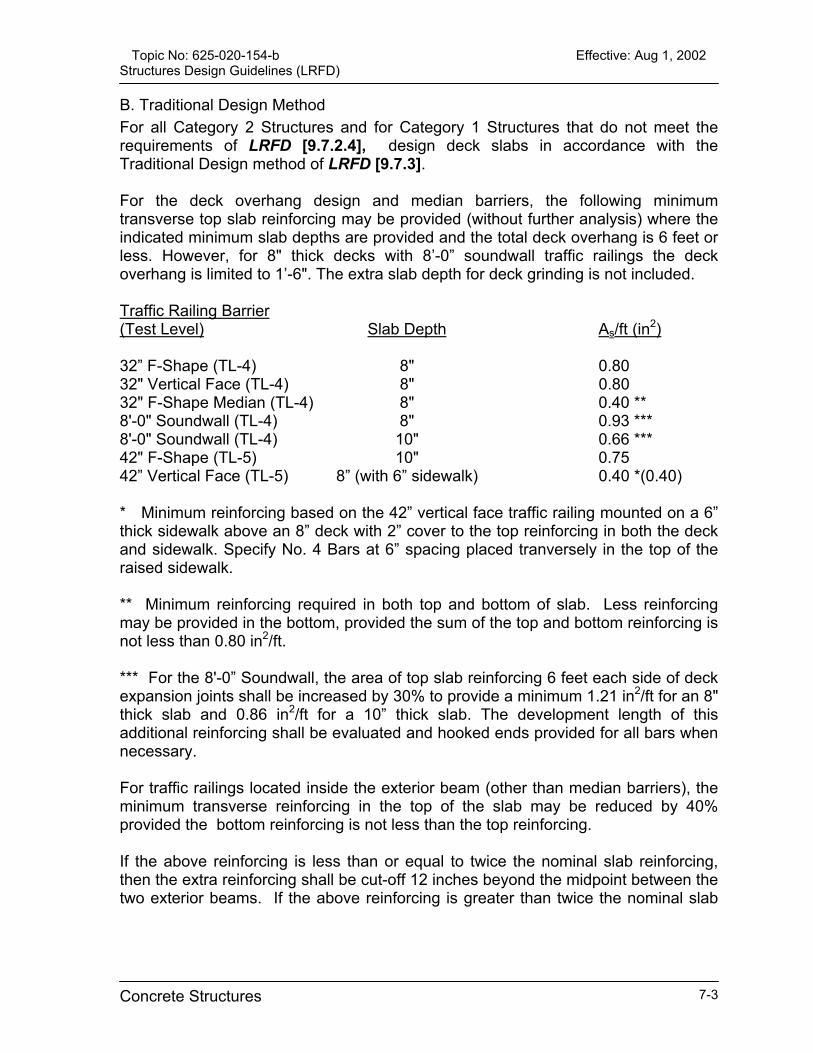
Topic No: 625-020-154-b Effective: Aug 1, 2002 Structures Design Guidelines (LRFD)
B. Traditional Design Method For all Category 2 Structures and for Category 1 Structures that do not meet the requirements of LRFD [9.7.2.4], design deck slabs in accordance with the Traditional Design method of LRFD [9.7.3]. For the deck overhang design and median barriers, the following minimum transverse top slab reinforcing may be provided (without further analysis) where the indicated minimum slab depths are provided and the total deck overhang is 6 feet or less. However, for 8" thick decks with 8’-0” soundwall traffic railings the deck overhang is limited to 1’-6". The extra slab depth for deck grinding is not included. Traffic Railing Barrier (Test Level) Slab Depth As/ft (in2)
32” F-Shape (TL-4) 8" 0.80 32" Vertical Face (TL-4) 8" 0.80 32" F-Shape Median (TL-4) 8" 0.40 ** 8'-0" Soundwall (TL-4) 8" 0.93 *** 8'-0" Soundwall (TL-4) 10" 0.66 *** 42" F-Shape (TL-5) 10" 0.75 42” Vertical Face (TL-5) 8” (with 6” sidewalk) 0.40 *(0.40) * Minimum reinforcing based on the 42” vertical face traffic railing mounted on a 6” thick sidewalk above an 8” deck with 2” cover to the top reinforcing in both the deck and sidewalk. Specify No. 4 Bars at 6” spacing placed tranversely in the top of the raised sidewalk. ** Minimum reinforcing required in both top and bottom of slab. Less reinforcing may be provided in the bottom, provided the sum of the top and bottom reinforcing is not less than 0.80 in2/ft.
*** For the 8'-0” Soundwall, the area of top slab reinforcing 6 feet each side of deck expansion joints shall be increased by 30% to provide a minimum 1.21 in2/ft for an 8" thick slab and 0.86 in2/ft for a 10” thick slab. The development length of this additional reinforcing shall be evaluated and hooked ends provided for all bars when necessary. For traffic railings located inside the exterior beam (other than median barriers), the minimum transverse reinforcing in the top of the slab may be reduced by 40% provided the bottom reinforcing is not less than the top reinforcing. If the above reinforcing is less than or equal to twice the nominal slab reinforcing, then the extra reinforcing shall be cut-off 12 inches beyond the midpoint between the two exterior beams. If the above reinforcing is greater than twice the nominal slab
Concrete Structures 7-3
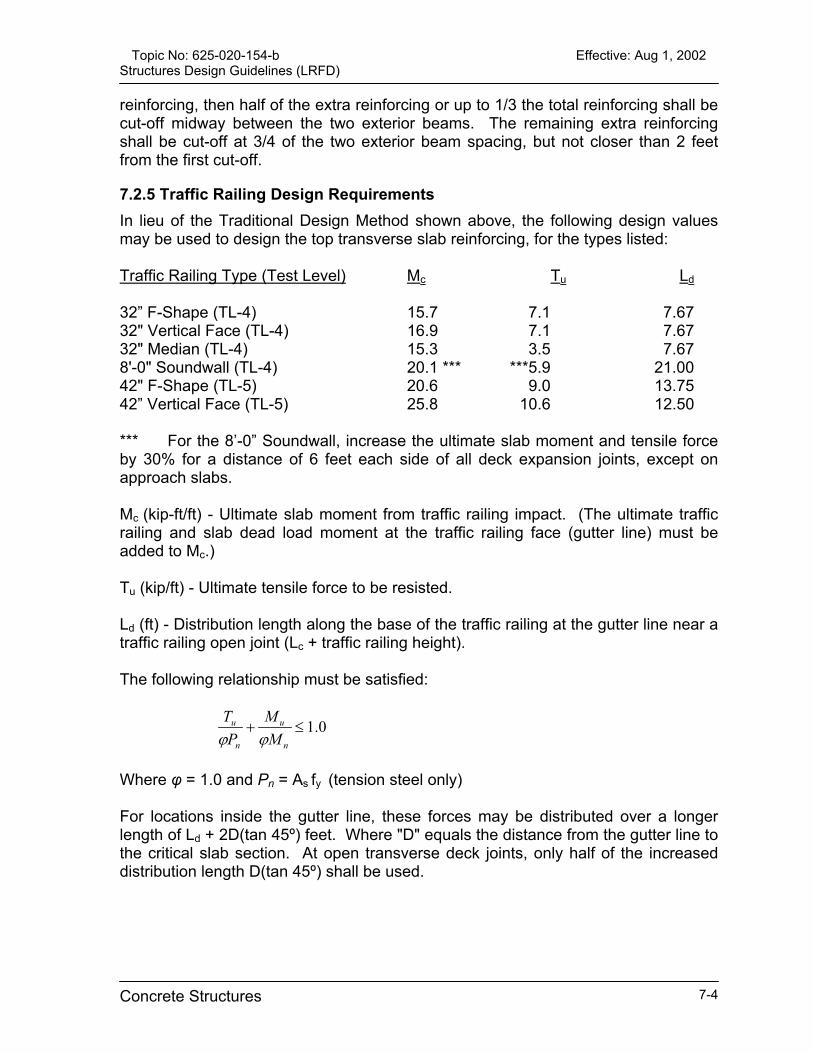
Topic No: 625-020-154-b Effective: Aug 1, 2002 Structures Design Guidelines (LRFD)
reinforcing, then half of the extra reinforcing or up to 1/3 the total reinforcing shall be cut-off midway between the two exterior beams. The remaining extra reinforcing shall be cut-off at 3/4 of the two exterior beam spacing, but not closer than 2 feet from the first cut-off.
7.2.5 Traffic Railing Design Requirements In lieu of the Traditional Design Method shown above, the following design values may be used to design the top transverse slab reinforcing, for the types listed:
Traffic Railing Type (Test Level) Mc Tu Ld
32” F-Shape (TL-4) 15.7 7.1 7.67 32" Vertical Face (TL-4) 16.9 7.1 7.67 32" Median (TL-4) 15.3 3.5 7.67 8'-0" Soundwall (TL-4) 20.1 *** ***5.9 21.00 42" F-Shape (TL-5) 20.6 9.0 13.75 42” Vertical Face (TL-5) 25.8 10.6 12.50 *** For the 8’-0” Soundwall, increase the ultimate slab moment and tensile force by 30% for a distance of 6 feet each side of all deck expansion joints, except on approach slabs.
Mc (kip-ft/ft) - Ultimate slab moment from traffic railing impact. (The ultimate traffic railing and slab dead load moment at the traffic railing face (gutter line) must be added to Mc.)
Tu (kip/ft) - Ultimate tensile force to be resisted.
Ld (ft) - Distribution length along the base of the traffic railing at the gutter line near a traffic railing open joint (Lc + traffic railing height). The following relationship must be satisfied:
0.1≤+n
u
n
u
MM
PT
ϕϕ
Where φ = 1.0 and Pn = As fy (tension steel only) For locations inside the gutter line, these forces may be distributed over a longer length of Ld + 2D(tan 45º) feet. Where "D" equals the distance from the gutter line to the critical slab section. At open transverse deck joints, only half of the increased distribution length D(tan 45º) shall be used.
Concrete Structures 7-4

Topic No: 625-020-154-b Effective: Aug 1, 2002 Structures Design Guidelines (LRFD)
For flat slab bridges the transverse moment due to the traffic railing dead load may be neglected. The area of transverse top slab reinforcing determined by analysis, for flat slab bridges with edge traffic railings shall not be less than 0.30 in2/ft within 4 feet of the gutter line for any TL-4 traffic railing or 0.40 in2/ft within 10 feet of the gutter line for any TL-5 railing. When more than 50% of the total transverse reinforcing must be cut off, a minimum of 2 feet shall separate the cut-off locations. For traffic railings located inside the exterior beam, or greater than 5’-0” from the edge of flat bridges, the designer may assume that only 60% of the ultimate slab moment and tensile force are transferred to the deck slab on either side of the traffic railing.
7.2.6 Reinforcing Steel over Intermediate Piers or Bents When CIP slabs are made composite with simple span concrete beams, and are cast continuous over intermediate piers or bents, design supplemental longitudinal reinforcing in the tops of slabs. Sized, space, and place reinforcing in accordance with the following criteria: A. No. 5 Bars placed between the continuous, longitudinal reinforcing bars. B. A minimum of 35 feet in length or 2/3 span whichever is less. C. Placed symmetrically about the centerline of the pier or bent, with alternating
bars staggered 5 feet.
7.2.7 Structures Continuous for Live Load In structures designed continuous for live load, design supplemental longitudinal reinforcing extended beyond the point where the slab is in tension under any load combination.
7.2.8 Concrete Decks on Continuous Steel Girders For longitudinal reinforcing steel within the negative moment regions of continuous, composite steel girder superstructures, comply with the requirements of LRFD [6.10.3.7]. In addition, design the remainder of the deck with No. 5 longitudinal steel at 12 inch spacing in the top of the slab and No. 4 Bars at 12 inch spacing in the bottom of the slab.
7.2.9 Skewed Decks [9.7.1.3] A. Reinforcing Placement when the Slab Skew is 15 Degrees or less: Place the transverse reinforcement parallel to the skew for the entire length of the slab.
Concrete Structures 7-5
Topic No: 625-020-154-b Effective: Aug 1, 2002 Structures Design Guidelines (LRFD)
B. Reinforcing Placement when the Slab Skew is more than 15 Degrees: Place the required transverse reinforcement perpendicular to the centerline of span. In this case, because the typical required transverse reinforcement cannot be placed full-width in the triangular shaped portions of the ends of the slab, the required amount of longitudinal reinforcing shall be doubled for a distance along the span equal to the beam spacing. In addition, three No. 5 Bars at 6” spacing, full-width, shall be placed parallel to the end skew in the top of each end of the slab. Note: Regardless of the angle of skew, the traffic railing reinforcement cast into the slab need not be skewed.
7.2.10 Temperature and Shrinkage Reinforcement For all cast in place decks, design temperature and shrinkage reinforcement per LRFD [5.10.8] except do not exceed 12” spacing and the minimum bar size is No 4.
7.3 Reinforcing Steel [5.4.3] Steel reinforcing for concrete design shall be ASTM A615, Grade 60.
7.4 Prestressed, Pretensioned Components
7.4.1 Prestressed Piling [5.13.4.3] For prestressed piling not subjected to significant flexure under service or impact loading, strand development shall be in accordance with LRFD [5.11.4] and [5.8.2.3]. Bending that produces cracking in the pile, such as that resulting from ship impact loading, is considered significant. A pile embedment of 4 feet into a footing is considered adequate to develop the strength of the pile. For the standard square FDOT prestressed concrete piles (12 through 30 inch), a pile embedment of 4 feet into a reinforced concrete footing is considered adequate to develop the bending strength of the pile. The pile must be solid, or the pile void filled with structural concrete, within the 4-foot embedment length. A 1 foot embedment shall be considered a pinned head condition. For the pinned pile head condition the strand development shall be in accordance with LRFD [5.11.4] and [5.8.2.3]. The bending capacity versus pile cap embedment length relationship for prestressed piles with widths or diameters larger than 30 inches shall be established on a case-by-case basis.
Concrete Structures 7-6
Topic No: 625-020-154-b Effective: Aug 1, 2002 Structures Design Guidelines (LRFD)
Commentary: The FDOT Structures Research Center conducted full scale testing of two 30 inch square concrete piles reinforced with prestressing steel and an embedded steel pipe. The piles, which were embedded 4 feet into a reinforced pile cap, developed the calculated theoretical bending strength of the section without strand slip. See FDOT Report No 98-9 “Testing of Pile to Pile Cap Moment Connection for 30” Prestressed Concrete Pipe-Pile”. It was concluded that the confinement effects of the pile cap serve to improve the bond characteristics of the strand.
7.4.2 Prestressed Beams The use of ASTM A416, Grade 270, low-relaxation, straight, prestressing strands is preferred for the design of prestressed beams. However, the requirements stipulated hereinafter apply to simply supported, fully pretensioned beams, whether of straight or depressed (draped) strand profile, except where specifically noted otherwise. A. Bridges that contain varying span lengths, skew angles, beam spacing, beam
loads, or other design criteria may result in very similar individual designs. The designer should consider the individual beams designs as a first trial subject to modifications by combining similar designs into groups of common materials and stranding based upon the following priorities:
1.) 28-Day Compressive Concrete Strength (f’c) 2.) Stranding (size, number, and location) 3.) Compressive Concrete Strength at Release (f’ci) 4.) Shielding (Debonding)*
*Note: Full length shielding of strands in some beams to facilitate casting bed utilization of beams with slightly different strand patterns is prohibited. Commentary: Grouping beam designs in accordance with the priority list maximizes casting bed usage and minimizes variations in materials and stranding. B. In analyzing stresses and/or determining the required length of debonding,
stresses shall be limited to the following values: 1.) Tension at top of beam at release (straight strand only):
Outer 15 percent of design span:
ft = 6√ f’ci (psi)
ft = 12√ f’ci (psi)
Center 70 percent of design span:
2.) Tension at top of beam at release (depressed strands only): ft = 6√ f’ci (psi)
Concrete Structures 7-7

Topic No: 625-020-154-b Effective: Aug 1, 2002 Structures Design Guidelines (LRFD)
C. In order to achieve uniformity and consistency in designing strand patterns, the
following parameters shall apply: 1.) Strand patterns utilizing an odd number of strands per row (a strand located on
the centerline of beam) and a minimum side cover (centerline of strand to face of concrete) of 3 inches are required for all AASHTO and Florida Bulb-Tee beam sections except AASHTO Type V and VI beams for which a strand pattern with an even number of strands per row shall be utilized.
2.) Use of “L-shaped” longitudinal bars in the webs and flanges in end zone areas. 3.) The minimum compressive concrete strength at release shall be 4.0 ksi or 0.6
f’c, whichever is the greater. Higher release strengths may be used and specified when required by the designer but generally should not exceed 0.8 f’c.
4.) Prestressed beams shall be designed and specified to conform to classes and related strengths of concrete as shown in Table 7.1.
5.) The use of time-dependent, inelastic creep and shrinkage is not allowed in the design of simple span, pretensioned components either during design or construction. Prestress loss must be calculated in accordance with LRFD [5.9.5].
Commentary: The FDOT cannot practically control, nor require the Contractor to control, the construction sequence and materials for simple span precast, prestressed beams. To benefit from the use of refined time-dependent analysis, literally every prestressed beam design would have to be re-analyzed using the proper construction times, temperature, humidity, material properties, etc. of both the beam and the yet-to-be-cast composite slab.
6.) Stress and camber calculations for the design of simple span, pretensioned components shall be based upon the use of transformed section properties.
7.) When wide-top beams such as bulb-tees and AASHTO Types V and VI beams are used in conjunction with stay-in-place metal forms, the designer shall evaluate the edges of flanges of those beams to safely and adequately support the self-weight of the forms, concrete, and construction load specified in Section 400 of the FDOT Standard Specifications for Road and Bridge Construction.
8.) The design thickness of the composite slab shall be provided from the top of the stay-in-place metal form to the finished slab surface, and the superstructure concrete quantity shall not include the concrete required to fill the form flutes.
Concrete Structures 7-8
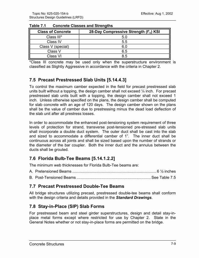
Topic No: 625-020-154-b Effective: Aug 1, 2002 Structures Design Guidelines (LRFD)
Table 7.1 Concrete Classes and Strengths Class of Concrete 28-Day Compressive Strength (f’c) KSI
Class III* 5.0 Class IV 5.5
Class V (special) 6.0 Class V 6.5 Class VI 8.5
*Class III concrete may be used only when the superstructure environment is classified as Slightly Aggressive in accordance with the criteria in Chapter 2.
7.5 Precast Prestressed Slab Units [5.14.4.3] To control the maximum camber expected in the field for precast prestressed slab units built without a topping, the design camber shall not exceed ¼ inch. For precast prestressed slab units built with a topping, the design camber shall not exceed 1 inch. Unless otherwise specified on the plans, the design camber shall be computed for slab concrete with an age of 120 days. The design camber shown on the plans shall be the value of camber due to prestressing minus the dead load deflection of the slab unit after all prestress losses. In order to accommodate the enhanced post-tensioning system requirement of three levels of protection for strand, transverse post-tensioned pre-stressed slab units shall incorporate a double duct system. The outer duct shall be cast into the slab and sized to accommodate a differential camber of 1”. The inner duct shall be continuous across all joints and shall be sized based upon the number of strands or the diameter of the bar coupler. Both the inner duct and the annulus between the ducts shall be grouted.
7.6 Florida Bulb-Tee Beams [5.14.1.2.2] The minimum web thicknesses for Florida Bulb-Tee beams are: A. Pretensioned Beams ............................................................................. 6 ½ inches B. Post-Tensioned Beams .................................................................... See Table 7.5
7.7 Precast Prestressed Double-Tee Beams All bridge structures utilizing precast, prestressed double-tee beams shall conform with the design criteria and details provided in the Standard Drawings.
7.8 Stay-in-Place (SIP) Slab Forms For prestressed beam and steel girder superstructures, design and detail stay-in-place metal forms except where restricted for use by Chapter 2. State in the General Notes whether or not stay-in-place forms are permitted on the bridge.
Concrete Structures 7-9
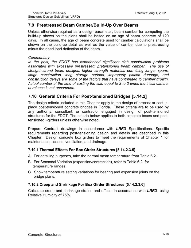
Topic No: 625-020-154-b Effective: Aug 1, 2002 Structures Design Guidelines (LRFD)
7.9 Prestressed Beam Camber/Build-Up Over Beams Unless otherwise required as a design parameter, beam camber for computing the build-up shown on the plans shall be based on an age of beam concrete of 120 days. In all cases, the age of beam concrete used for camber calculations shall be shown on the build-up detail as well as the value of camber due to prestressing minus the dead load deflection of the beam. Commentary: In the past, the FDOT has experienced significant slab construction problems associated with excessive prestressed, pretensioned beam camber. The use of straight strand beam designs, higher strength materials permitting longer spans, stage construction, long storage periods, improperly placed dunnage, and construction delays are some of the factors that have contributed to camber growth. Actual camber at the time of casting the slab equal to 2 to 3 times the initial camber at release is not uncommon.
7.10 General Criteria For Post-tensioned Bridges [5.14.2] The design criteria included in this Chapter apply to the design of precast or cast-in-place post-tensioned concrete bridges in Florida. These criteria are to be used by any authority, consultant, or contractor engaged in design of post-tensioned structures for the FDOT. The criteria below applies to both concrete boxes and post-tensioned I-girders unless otherwise noted. Prepare Contract drawings in accordance with LRFD Specifications. Specific requirements regarding post-tensioning design and details are described in this Chapter. Design concrete box girders to meet the requirements of Chapter 1 for maintenance, access, ventilation, and drainage.
7.10.1 Thermal Effects For Box Girder Structures [5.14.2.3.5] A. For detailing purposes, take the normal mean temperature from Table 6.2. B. For Seasonal Variation (expansion/contraction), refer to Table 6.2 for
temperature ranges. C. Show temperature setting variations for bearing and expansion joints on the
bridge plans.
7.10.2 Creep and Shrinkage For Box Girder Structures [5.14.2.3.6] Calculate creep and shrinkage strains and effects in accordance with LRFD using Relative Humidity of 75%.
Concrete Structures 7-10
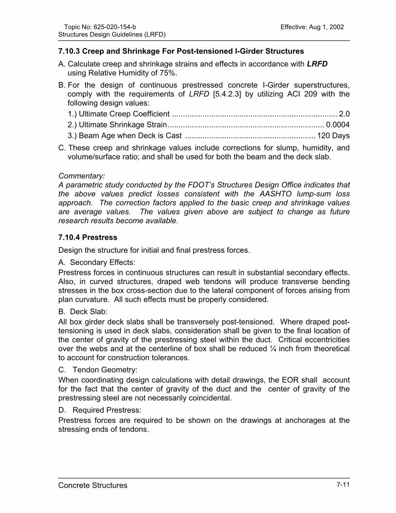
Topic No: 625-020-154-b Effective: Aug 1, 2002 Structures Design Guidelines (LRFD)
7.10.3 Creep and Shrinkage For Post-tensioned I-Girder Structures A. Calculate creep and shrinkage strains and effects in accordance with LRFD
using Relative Humidity of 75%. B. For the design of continuous prestressed concrete I-Girder superstructures,
comply with the requirements of LRFD [5.4.2.3] by utilizing ACI 209 with the following design values: 1.) Ultimate Creep Coefficient ............................................................................ 2.0 2.) Ultimate Shrinkage Strain........................................................................ 0.0004 3.) Beam Age when Deck is Cast ............................................................ 120 Days
C. These creep and shrinkage values include corrections for slump, humidity, and volume/surface ratio; and shall be used for both the beam and the deck slab.
Commentary: A parametric study conducted by the FDOT’s Structures Design Office indicates that the above values predict losses consistent with the AASHTO lump-sum loss approach. The correction factors applied to the basic creep and shrinkage values are average values. The values given above are subject to change as future research results become available.
7.10.4 Prestress Design the structure for initial and final prestress forces. A. Secondary Effects: Prestress forces in continuous structures can result in substantial secondary effects. Also, in curved structures, draped web tendons will produce transverse bending stresses in the box cross-section due to the lateral component of forces arising from plan curvature. All such effects must be properly considered. B. Deck Slab: All box girder deck slabs shall be transversely post-tensioned. Where draped post-tensioning is used in deck slabs, consideration shall be given to the final location of the center of gravity of the prestressing steel within the duct. Critical eccentricities over the webs and at the centerline of box shall be reduced ¼ inch from theoretical to account for construction tolerances. C. Tendon Geometry: When coordinating design calculations with detail drawings, the EOR shall account for the fact that the center of gravity of the duct and the center of gravity of the prestressing steel are not necessarily coincidental. D. Required Prestress: Prestress forces are required to be shown on the drawings at anchorages at the stressing ends of tendons.
Concrete Structures 7-11

Topic No: 625-020-154-b Effective: Aug 1, 2002 Structures Design Guidelines (LRFD)
E. Internal/External Tendons: External tendons shall remain external to the section without entering the top or bottom slab. F. Strand Couplers: Strand couplers as described in LRFD [5.4.5] are not allowed. G. Post-tensioned Beams: In designing pretensioned beams made continuous by field-applied post-tensioning, the pretensioning shall meet the following minimum criteria:
1.) The pretensioning acting alone shall comply with the minimum steel requirements of LRFD [5.7.3.3.2].
2.) The pretensioning shall be capable of resisting all loads applied prior to post-tensioning, including a superimposed dead load equal to 50% of the uniform weight of the beam, without exceeding the stress limitation for pretensioned concrete construction.
3.) The initial mid span camber at release, including the effect of the dead load of the beam, is at least ½ inch. In computing the initial camber, the value of the modulus of elasticity of the concrete, Ec, shall be in accordance with Section 7.1 for the minimum required strength of concrete at release of the pretensioning force. The pretensioning force in the strands shall be reduced by losses due to elastic shortening and steel relaxation.
4.) Anchorage zones of post-tensioning tendons as well as beam segments in which ducts deviate both horizontally and vertically require integrated drawings showing all post-tensioning hardware and reinforcing steel.
5.) In designing pretensioned beams made continuous by field-applied post-tensioning, the pretensioning shall be designed such that the following minimum criteria are satisfied:
Concrete Structures 7-12
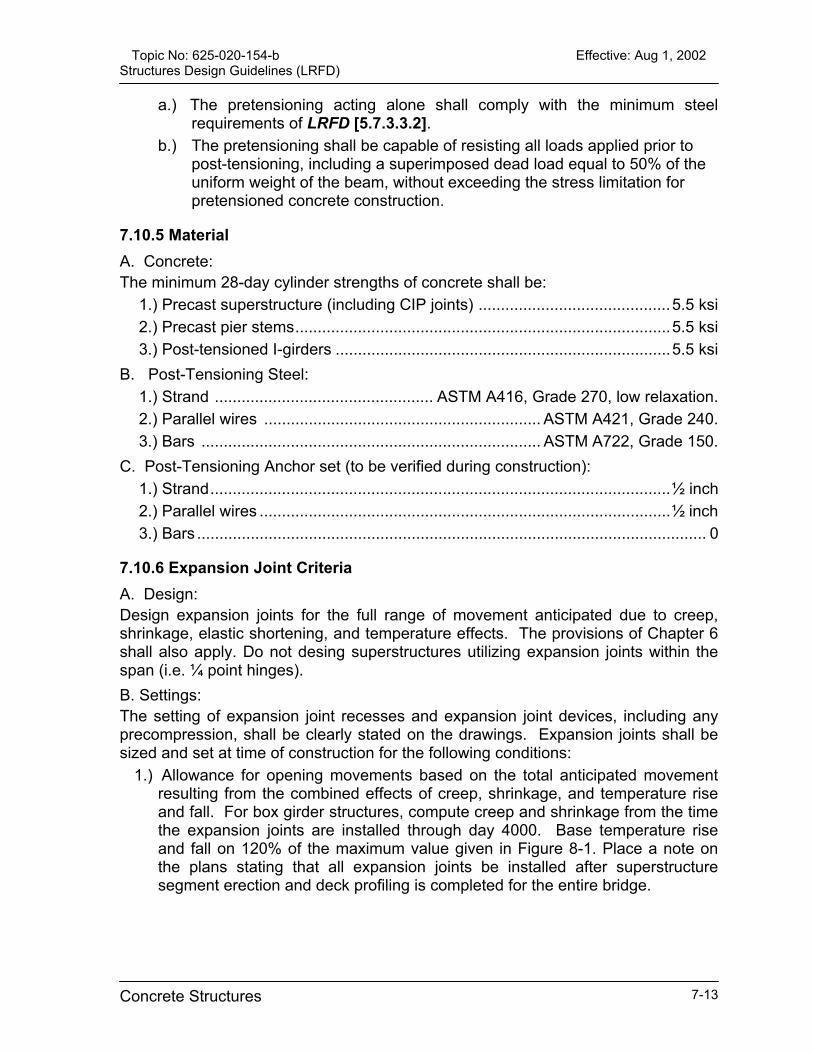
Topic No: 625-020-154-b Effective: Aug 1, 2002 Structures Design Guidelines (LRFD)
a.) The pretensioning acting alone shall comply with the minimum steel requirements of LRFD [5.7.3.3.2].
b.) The pretensioning shall be capable of resisting all loads applied prior to post-tensioning, including a superimposed dead load equal to 50% of the uniform weight of the beam, without exceeding the stress limitation for pretensioned concrete construction.
7.10.5 Material A. Concrete: The minimum 28-day cylinder strengths of concrete shall be:
1.) Precast superstructure (including CIP joints) ...........................................5.5 ksi 2.) Precast pier stems....................................................................................5.5 ksi 3.) Post-tensioned I-girders ...........................................................................5.5 ksi
B. Post-Tensioning Steel: 1.) Strand ................................................. ASTM A416, Grade 270, low relaxation. 2.) Parallel wires .............................................................. ASTM A421, Grade 240. 3.) Bars ............................................................................ ASTM A722, Grade 150.
C. Post-Tensioning Anchor set (to be verified during construction): 1.) Strand.......................................................................................................½ inch 2.) Parallel wires ............................................................................................½ inch 3.) Bars .................................................................................................................. 0
7.10.6 Expansion Joint Criteria A. Design: Design expansion joints for the full range of movement anticipated due to creep, shrinkage, elastic shortening, and temperature effects. The provisions of Chapter 6 shall also apply. Do not desing superstructures utilizing expansion joints within the span (i.e. ¼ point hinges). B. Settings: The setting of expansion joint recesses and expansion joint devices, including any precompression, shall be clearly stated on the drawings. Expansion joints shall be sized and set at time of construction for the following conditions:
1.) Allowance for opening movements based on the total anticipated movement resulting from the combined effects of creep, shrinkage, and temperature rise and fall. For box girder structures, compute creep and shrinkage from the time the expansion joints are installed through day 4000. Base temperature rise and fall on 120% of the maximum value given in Figure 8-1. Place a note on the plans stating that all expansion joints be installed after superstructure segment erection and deck profiling is completed for the entire bridge.
Concrete Structures 7-13
Topic No: 625-020-154-b Effective: Aug 1, 2002 Structures Design Guidelines (LRFD)
2.) To account for the larger amount of opening movement, expansion devices should be set precompressed to the maximum extent possible. In calculations allow for an assumed setting temperature of 85 degrees F. Provide a table on the plans giving precompression settings according to the prevailing conditions. Size Expansion devices and set to remain in compression through the full range of design temperature from their initial installation until a time of 4,000 days.
3.) A table of setting adjustments shall be provided to account for temperature variation at the time of installation. The table shall indicate the ambient air temperature at time of installation, and adjustments shall be calculated for the difference between the ambient air temperature and the mean temperature given in Figure 6-1.
C. Armoring: Concrete corners under expansion joint devices shall be provided with adequate steel armoring to prevent spalling or other damage under traffic. It is recommended that the armor be at least 4x4x5/8 galvanized angles anchored to the concrete with welded studs or similar devices. Horizontal concrete surfaces supporting the expansion joint device and running flush with the armoring shall have a finish acceptable for the device. All armoring shall have adequate vent holes to assure proper filling and compaction of the concrete under the armor. D. Details For Post-Tensioned Bridges: At expansion joints, provide a recess and continuous expansion joint device seat to receive the assembly, anchor bolts, and frames of the expansion joint, i.e. a finger or modular type joint. In the past, block-outs have been made in such seats to provide access for stressing jacks to the upper longitudinal tendon anchors set as high as possible in the anchor block. Lower the upper tendon anchors and re-arrange the anchor layout as necessary to provide access for the stressing jacks.
Concrete Structures 7-14
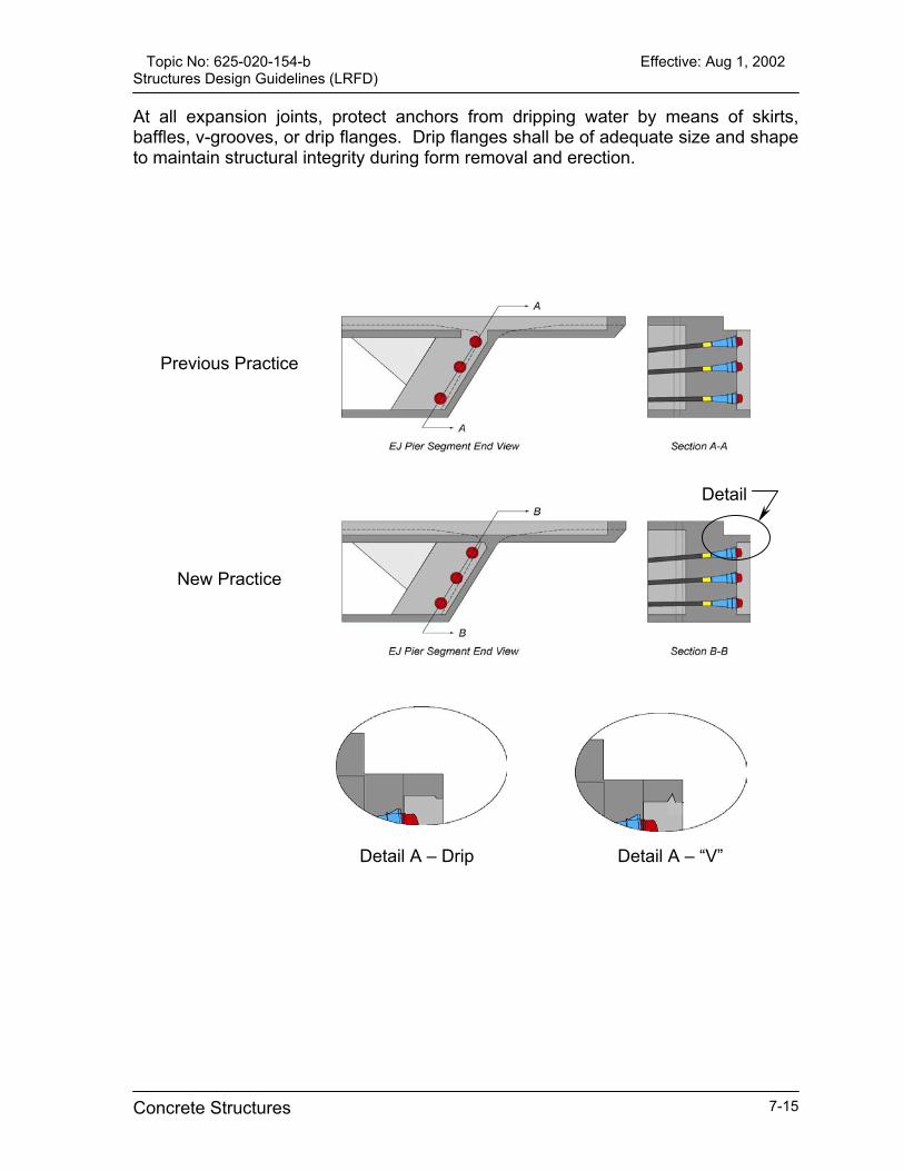
Topic No: 625-020-154-b Effective: Aug 1, 2002 Structures Design Guidelines (LRFD)
At all expansion joints, protect anchors from dripping water by means of skirts, baffles, v-grooves, or drip flanges. Drip flanges shall be of adequate size and shape to maintain structural integrity during form removal and erection.
Detail
Previous Practice
New Practice
Detail A – Drip Detail A – “V”
Concrete Structures 7-15
Topic No: 625-020-154-b Effective: Aug 1, 2002 Structures Design Guidelines (LRFD)
7.10.7 Erection Schedule and Construction System A typical erection schedule and anticipated construction system shall be incorporated into the design documents in an outlined, schematic form. The assumed erection loads, along with times of application and removal of each of the erection loads, shall be clearly stated in the plans.
7.10.8 Const. Data Elev. and Camber Curve For Box Girder Structures A. General: Construction Data Elevations shall be based on the vertical and horizontal highway geometry; whereas, the Camber Curve shall be calculated and based on the assumed erection loads used in the design and the assumed construction sequence. B. Construction Data Elevations: This information shall be based on the highway geometry and shall be given in 3D space with “x”, “y”, and “z” coordinates. The data points shall be located at the centerline of the box and over each web of the box(es). C. Camber Curve: Camber Curve data shall be provided at the centerline of the box. Camber curve data is the opposite of deflections. Camber is the amount by which the concrete profile at the time of casting must differ from the theoretical geometric profile grade (generally a straight line) in order to compensate for all structural dead load, post-tensioning, long and short term time dependent deformations (creep and shrinkage), and effects of construction loads and sequence of erection.
7.10.9 Final Computer Run For Box Girder Structures It is required that the final design shall be proven by a full longitudinal analysis taking into account the assumed construction process and final long term service condition, including all time related effects. The analysis shall be made using a computer program approved by SDO.
7.10.10 Integrated Drawings Congested areas of post-tensioned concrete structures shall be shown on integrated drawings with an assumed post-tensioning system. Such areas include, but are not necessarily limited to, anchorages zones, areas containing embedded items for the assumed post-tensioning system, areas where post-tensioning ducts deviate both in the vertical and transverse directions, and other highly congested areas as determined by the engineer and/or the Department. For curved structures, evaluate and accomodate possible conflicts between webs and external tendons. Also, check for conflicts between future post-tensioning tendons and permanent tendons.
Concrete Structures 7-16
Topic No: 625-020-154-b Effective: Aug 1, 2002 Structures Design Guidelines (LRFD)
The assumed post-tensioning system, embedded items, etc. shall be selected in a manner that will accommodate competitive systems using standard anchorage sizes of 4-0.6” dia, 7-0.6” dia, 12-0.6” dia, 19-0.6 dia and 27-0.6” dia. Integrated drawings utilizing the assumed system shall be defined to a scale and quality required to show double-line reinforcing and post-tensioning steel in two-dimension (2-D) and, when necessary, in complete three-dimension (3-D) drawings and details.
7.10.11 Post-tensioning Anchorages in Box Girders Post-tensioning anchorages that are required in either the top or bottom slab of box girder bridges, whether for permanent or temporary post-tensioning, shall be anchored by means of interior “blisters,” face anchors or other approved means. Blockouts that extend either to the interior or exterior surfaces of the slabs are not permitted.
7.10.12 Epoxy Joining of Segments All joints between precast segmental bridge segments shall contain epoxy on both faces. This requirement applies to substructure and superstructure precast units. Dry segment joints are not allowed.
7.11 Post-Tensioning Design [5.4.6][5.10.3.3]
7.11.1 Ducts and Tendons Show offset dimensions to post-tensioning duct trajectories from fixed surfaces or clearly defined reference lines at intervals not exceeding 5 feet. When the radius of curvature of a duct exceeds one-half degree per foot, offsets shall be shown at intervals not exceeding 30 inches. In regions of tight reverse curvature of short sections of tendons, offsets shall be shown at sufficiently frequent intervals to clearly define the reverse curve. Curved ducts that run parallel to each other or around a void or re-entrant corner shall be sufficiently encased in concrete and reinforced as necessary to avoid radial failure (pull-out into the other duct or void). In the case of approximately parallel ducts, the EOR shall consider the arrangement, installation, stressing sequence, and grouting in order to avoid potential problems with cross-grouting of ducts. Detail post-tensioned bulb-tee beams to utilize round metal ducts only.
Concrete Structures 7-17

Topic No: 625-020-154-b Effective: Aug 1, 2002 Structures Design Guidelines (LRFD)
Table 7.2 Minimum Center-to-Center Duct Spacing:
Post Tensioned Bridge Type *Minimum Center To Center Longitudinal Duct Spacing
Precast Segmental Balanced Cantilever
Cast-In-Place Balanced Cantilever
8”, 2 times outer duct diameter, or outer duct diameter plus 4 ½ inches whichever is greater.
Spliced I-Girder Bridges 4 inches, outer duct diameter plus 1.5 times maximum aggregate size, or outer duct diameter plus 2 inches whichever is greater.
C.I.P. Voided Slab Bridges C.I.P. Multi-Cell Bridges
When all ducts are in a vertical plane – 4 inches, outer duct diameter plus 1.5 times maximum aggregate size, or outer duct diameter plus 2 inches whichever is greater. **For two or more ducts set side by side - outer duct diameter plus 3 inches.
* - Bundled tendons shall not be allowed. ** - The 3 inch measurement shall be measured in a horizontal plane.
Ducts for all post-tensioning bars shall be sized to be ½ inch larger than the diameter of the bar coupler. Internal post-tensioning ducts are required to be positively sealed with duct couplers at all segment joints to eliminate the possibility of contamination. Therefore, internal tendons shall be designed and detailed to be perpendicular to all segment joints and all closure pours shall be a minimum of 18 inches.
To allow room for the installation of duct couplers, detail all external tendons to provide a 1 ½ inch clearance between the duct surface and the face of the concrete. Diablos are not allowed. Detail both internal and external tendons to be placed in steel pipes when the radius is less than shown in the table below. Detail all deviation saddles to contain steel pipe regardless of the tendon radius. Table 7.3 Minimum Tendon Radius
Tendon Size Minimum Radius (ft) 19-0.5” dia, 12-0.6” dia 8’ 31-0.5” dia, 19-0.6” dia 10’ 55-0.5” dia, 37-0.6” dia 13’
All balanced cantilever bridges shall utilize a minimum of 4 positive moment external draped continuity tendons (2 per web) that extend to adjacent pier diaphragms.
Concrete Structures 7-18
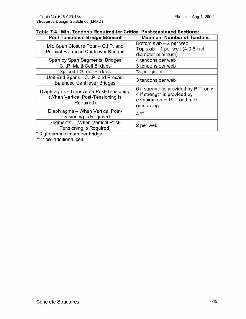
Topic No: 625-020-154-b Effective: Aug 1, 2002 Structures Design Guidelines (LRFD)
Table 7.4 Min. Tendons Required for Critical Post-tensioned Sections: Post Tensioned Bridge Element Minimum Number of Tendons
Mid Span Closure Pour – C.I.P. and Precast Balanced Cantilever Bridges
Bottom slab – 2 per web Top slab – 1 per web (4-0.6 inch diameter minimum)
Span by Span Segmental Bridges 4 tendons per web C.I.P. Multi-Cell Bridges 3 tendons per web Spliced I-Girder Bridges *3 per girder
Unit End Spans - C.I.P. and Precast Balanced Cantilever Bridges 3 tendons per web
Diaphragms - Transverse Post-Tensioning (When Vertical Post-Tensioning is
Required)
6 if strength is provided by P.T. only 4 if strength is provided by combination of P.T. and mild reinforcing
Diaphragms – When Vertical Post-Tensioning is Required 4 **
Segments – (When Vertical Post-Tensioning is Required) 2 per web
* 3 girders minimum per bridge. ** 2 per additional cell
Concrete Structures 7-19
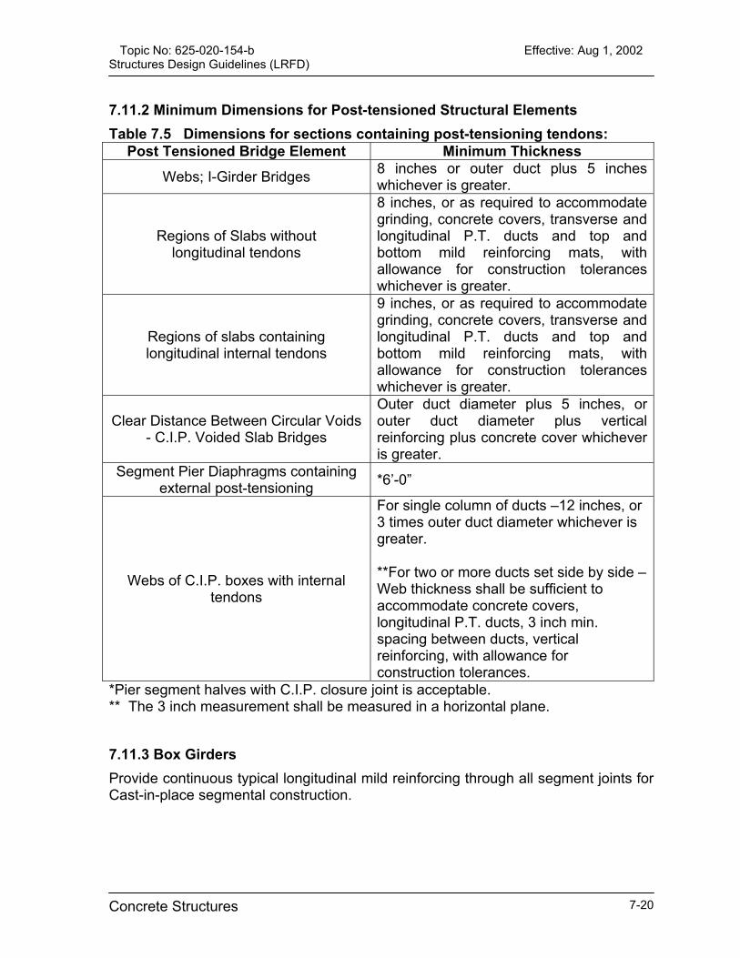
Topic No: 625-020-154-b Effective: Aug 1, 2002 Structures Design Guidelines (LRFD)
7.11.2 Minimum Dimensions for Post-tensioned Structural Elements Table 7.5 Dimensions for sections containing post-tensioning tendons:
Post Tensioned Bridge Element Minimum Thickness Webs; I-Girder Bridges 8 inches or outer duct plus 5 inches
whichever is greater.
Regions of Slabs without longitudinal tendons
8 inches, or as required to accommodate grinding, concrete covers, transverse and longitudinal P.T. ducts and top and bottom mild reinforcing mats, with allowance for construction tolerances whichever is greater.
Regions of slabs containing longitudinal internal tendons
9 inches, or as required to accommodate grinding, concrete covers, transverse and longitudinal P.T. ducts and top and bottom mild reinforcing mats, with allowance for construction tolerances whichever is greater.
Clear Distance Between Circular Voids - C.I.P. Voided Slab Bridges
Outer duct diameter plus 5 inches, or outer duct diameter plus vertical reinforcing plus concrete cover whichever is greater.
Segment Pier Diaphragms containing external post-tensioning *6’-0”
Webs of C.I.P. boxes with internal tendons
For single column of ducts –12 inches, or 3 times outer duct diameter whichever is greater. **For two or more ducts set side by side – Web thickness shall be sufficient to accommodate concrete covers, longitudinal P.T. ducts, 3 inch min. spacing between ducts, vertical reinforcing, with allowance for construction tolerances.
*Pier segment halves with C.I.P. closure joint is acceptable. ** The 3 inch measurement shall be measured in a horizontal plane.
7.11.3 Box Girders Provide continuous typical longitudinal mild reinforcing through all segment joints for Cast-in-place segmental construction.
Concrete Structures 7-20

Topic No: 625-020-154-b Effective: Aug 1, 2002 Structures Design Guidelines (LRFD)
All future post-tensioning shall utilize external tendons (bars or strands) and shall be detailed such that any one span can be strengthened independent of adjacent spans. All anchor blisters for tendons shall terminate no closer than 12 inches to a joint between segments. All interior blisters shall be set back from the joint a minimum of 12 inches. Provide a “V”-groove around the top slab blisters to isolate the anchorage from any free water. Transverse bottom slab ribs are not allowed. Full height diaphragms directing the deviation forces directly into the web and slab shall be used in lieu of deviation saddles with transverse bottom slab ribs.
Previous Practice New Practice Raised corner recesses in the top corner of pier segments at closure joints are not allowed. The typical cross section shall be continued to the face of the diaphragm. Tendon anchorages shall be located to make allowances for jack placement.
Previous Practice New Practice
7.11.4 Post-Tensioned I-Girders Individual deck block-outs for second stage post-tensioning access for I-Girder bridges shall not be allowed. Detail the deck in this region to be poured full width and extending one foot beyond the last anchorage upon completion of post-tensioning operations.
Concrete Structures 7-21

Topic No: 625-020-154-b Effective: Aug 1, 2002 Structures Design Guidelines (LRFD)
7.12 Adhesive Anchor Systems
7.12.1 General Adhesive Anchor Systems are used to attach new construction to existing concrete structures. Adhesive Anchor Systems incorporate an adhesive bonding material and steel bar anchors installed in clean, dry holes drilled in hardened concrete. Anchors may be reinforcing bars or threaded rods depending upon the application. Do not use Adhesive Anchor Systems to splice with existing reinforcing bars in either non-prestressed or prestressed concrete applications unless special testing is performed and special, proven construction techniques are utilized. For pre-approved Adhesive Anchor Systems, refer to the Department’s Qualified Products List (QPL), “Adhesive Bonding Material Systems for Structural Applications.” Comply with Section 937 of the Specifications. Require that Adhesive Anchors be installed in accordance with manufacturer’s recommendations for hole diameter and hole cleaning technique and meet the requirements of Section 416 of the Specifications. Commentary: Installation of Adhesive Anchor Systems in saturated, surface-dry holes; i.e., holes with damp surfaces but with no standing water, is not pre-approved or recommended by the Department. However, in the event such a condition is encountered during construction, the Department may consider approving continued installation, but only on an adjusted, case-by-case basis. The damp hole strength of products on the QPL has been determined to be approximately 75% of the required dry hole strength. Unless special circumstances dictate otherwise, design Adhesive Anchor Systems for a ductile failure. A ductile failure requires embedment sufficient to ensure that failure will occur by yielding of the steel. In order to produce ductile failure, the following embedments may be assumed: A. For Anchors in Tension: That length of embedment which will develop 125 percent (125%) of the specified yield strength or 100 percent (100%) of the specified tensile strength, whichever is less. B. For Anchors in Shear: An embedment equal to seventy percent (70%) of the embedment length determined for anchors in tension. In circumstances where ductile failure is not required, the design may be based upon the design strength of either the steel anchor or the adhesive bond, whichever is less.
Concrete Structures 7-22

Topic No: 625-020-154-b Effective: Aug 1, 2002 Structures Design Guidelines (LRFD)
Adhesive Anchor Systems meeting the specifications and design constraints of this article are permitted for horizontal, vertical, or downwardly inclined installations, only. Overhead or upwardly inclined installations of Adhesive Anchors are prohibited. Use QPL listed adhesive bonding to splice prestressed piling.
7.12.2 Notation The following notation is used in this Article: Ae = effective tensile stress area of steel anchor (may be taken as 75% of the gross
area for threaded anchors). [in2] An0 = (16d)2, effective area of a single Adhesive Anchor in tension; used in
calculating Ψgn (See Figure 7-1). [in2] An = effective area of a group of Adhesive Anchors in tension; used in calculating
Ψgn, defined as the rectangular area bounded by a perimeter spaced 8d from the center of the anchors and limited by free edges of concrete (See Figure 7-1). [in2]
Av0 = 4.5(c2), effective breakout area of a single Adhesive Anchor in shear; used in calculating Ψgv (See Figure 7-2). [in2]
Av = effective area of a group of Adhesive Anchors in shear and/or loaded in shear where the member thickness, h, is less than 1.5c; used in calculating Ψgv, (See Figure 7-2). [in2]
c = anchor edge distance from free edge to centerline of the anchor). [in] d = nominal diameter of Adhesive Anchor. [in] f’ c = minimum specified concrete strength. [ksi] fy = minimum specified yield strength of Adhesive Anchor steel. [ksi] fu = minimum specified ultimate strength of Adhesive Anchor steel. [ksi] h = concrete member thickness. [in] he = embedment depth of anchor. [in] Nc = tensile design strength as controlled by bond for Adhesive Anchors. [kips] Nn = nominal tensile strength of Adhesive Anchor. [kips] No = nominal tensile strength as controlled by concrete embedment for a single
Adhesive Anchor. [kips] Ns = design strength as controlled by Adhesive Anchor steel. [kips] Nu = factored tension load. [kips] s = Adhesive Anchor spacing (measured from centerlines of anchors). [in] When
using Type HSHV adhesives, the minimum anchor spacing is 12d, unless approved by the State Structures Engineer.
Vc = shear design strength as controlled by the concrete embedment for Adhesive Anchors. [kips]
Vs = design shear strength as controlled by Adhesive Anchor steel. [kips] Vu = factored shear load. [kips] T´ = 1.08 ksi nominal bond strength for general use products on the QPL (Type V
and Type HV). 1.83 ksi nominal bond strength for Type HSHV adhesive products on the QPL for traffic railing barrier retrofits only.
Concrete Structures 7-23

Topic No: 625-020-154-b Effective: Aug 1, 2002 Structures Design Guidelines (LRFD)
Øc = 0.85, capacity reduction factor for adhesive anchor controlled by the concrete embedment, (Øc =1.00 for extreme event load case).
Øs = 0.90, capacity reduction factor for adhesive anchor controlled by anchor steel. Ψe = modification factor, for strength in tension, to account for anchor edge
distance less than 8d (1.0 when c ≥ 8d). Ψgn = strength reduction factor for Adhesive Anchor groups in tension (1.0 when s ≥
16d). Ψgv = strength reduction factor for Adhesive Anchor groups in shear and single
Adhesive Anchors in shear influenced by member thickness (1.0 when s ≥ 3.0c and h ≥ 1.5c).
7.12.3 Design Requirements for Tensile Loading Use Equation 7-2 to determine the design tensile strength for Adhesive Anchor steel: Ns = Øs Ae fy [Eq. 7-2] Use Equation 7-3 to determine the design tensile strength for Adhesive Anchor bond: Nc = Øc Ψe Ψgn No [Eq. 7-3] where: No = T’πd he [Eq. 7-4] For anchors with a distance to a free edge of concrete less than 8d, but greater than or equal to 3d, a reduction factor, Ψe, as given by Equation 7-5 shall be used. For anchors located less than 3d from a free edge of concrete, an appropriate strength reduction factor shall be determined by special testing. For anchors with an edge distance greater than 8d, Ψe may be taken as 1.0. ψe = 0.70 + 0.30 (c/8d) [Eq. 7-5] For anchors loaded in tension and spaced closer than 16d, a reduction factor, Ψgn, given by Equation 7-6 shall be used. For anchor spacing greater than 16d, Ψgn shall be taken as 1.0. Ψgn = (An / Ano) [Eq. 7-6]
Concrete Structures 7-24

Topic No: 625-020-154-b Effective: Aug 1, 2002 Structures Design Guidelines (LRFD)
7.12.4 Design Requirements for Shear Loading Adhesive Anchors loaded in shear shall be embedded a distance of not less than 6d. For Adhesive Anchors loaded in shear, the design shear strength controlled by anchor steel is determined by Equation 7-7: Vs = Øs 0.7 As fy [Eq. 7-7] For Adhesive Anchors loaded in shear, the design shear strength controlled by concrete breakout for shear directed toward a free edge of concrete is determined by Equation 7-8: Vc = Øc Ψgv 0.4534 c1.5 √f’c [Eq. 7-8] For anchors spaced closer than 3.0c, a reduction factor, Ψgv, given by Equation 7-9 shall be used. For anchor spacing greater than 3.0c, Ψgv shall be taken as 1.0. Ψgv = Av /Av0 [Eq. 7-9]
7.12.5 Interaction of Tensile and Shear Loadings The following linear interaction between tension and shear loadings given by Equation 7-10 shall be used unless special testing is performed: (Nu / ØNn) + (Vn / ØVn) < 1.0 [Eq. 7-10] In Equation 7-10, Øn is the smaller of the design tensileAdhesive Anchor steel (Equation 7-2) or the design tensAdhesive Anchor bond (Equation 7-3). ØVn is the sstrength controlled by the Adhesive Anchor steel (Equatstrength as controlled by concrete breakout (Equation 7-8
Commentary: If Adhesive Anchor Systems are required to act as docomponents such that the existing reinforcing steel remlength, then the Adhesive Anchor System must be instadevelopment length of the existing reinforcing steel. reinforcing steel spacing, covers, etc. apply to both the ethe Adhesive Anchor System. There is, however, nAdhesive Anchor System to install anchors to a greater Article.
Concrete Structures
strength controlled by the ile strength as controlled by maller of the design shear ion 7-7) or the design shear ).
wels from existing concrete ains fully effective over its
lled to a depth equal to the In this case, the required xisting reinforcing steel and o additional benefit to the depth than required by this
7-25
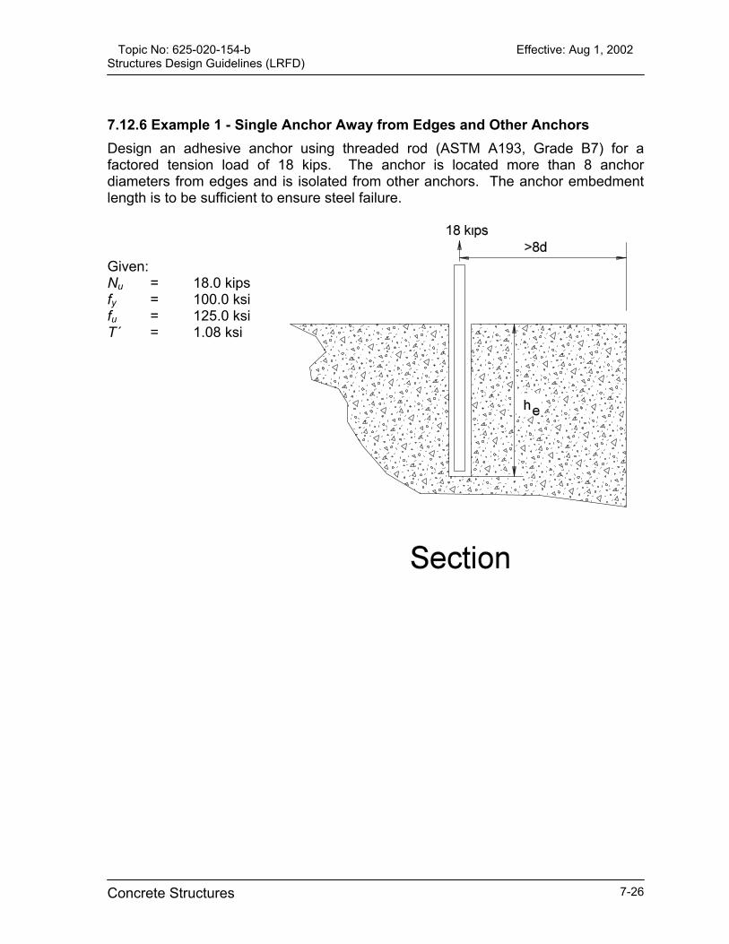
Topic No: 625-020-154-b Effective: Aug 1, 2002 Structures Design Guidelines (LRFD)
7.12.6 Example 1 - Single Anchor Away from Edges and Other Anchors Design an adhesive anchor using threaded rod (ASTM A193, Grade B7) for a factored tension load of 18 kips. The anchor is located more than 8 anchor diameters from edges and is isolated from other anchors. The anchor embedment length is to be sufficient to ensure steel failure.
Given: Nu = 18.0 kips fy = 100.0 ksi fu = 125.0 ksi T´ = 1.08 ksi
Concrete Structures 7-26

Topic No: 625-020-154-b Effective: Aug 1, 2002 Structures Design Guidelines (LRFD)
Design Procedure – Example 1 Calculation
Step 1 - Determine required rod diameter
Determine the required diameter of the threaded rod by setting the factored tension
load equal to the design steel strength. Nu = Ns
The effective area for the threaded rod may be taken as 75% of the gross area. As with reinforcing bars, the minimum specified yield strength of the rod is used to determine the
required diameter.
Ns = Øs Ae fy where: Øs = 0.9 Ae = 0.75 (πd 2/4) fy = 100 ksi
Substituting and solving for d: 18 = (0.9)[0.75 (πd2/4)](100) d = 0.583” therefore, use 5/8” threaded rod
Step 2 - Determine required embedment length to ensure steel failure
Basic equation for embedment length calculation. Since there are no edge or
spacing concerns, Ψe and Ψgn may be taken as unity.
Nc = Øc Ψe Ψgn No (for embedment) where: Øc = 0.85 Ψe ,Ψgn = 1.0 (no edge/spacing concern) No = Τ´ πd he
For ductile behavior it is necessary to embed the anchor sufficiently to develop 125% of the
yield strength or 100% of the ultimate strength, whichever is less.
Nc (req’d) = 1.25 Ae fy ≤ Ae fu
Determine the effective area for a 5/8” threaded rod:
Ae = 0.75 (π0.6252/4) Ae = 0.23 in2
Determine the required tension force, Nc(req’d), to ensure ductile behavior.
Nc(req’d) = 1.25 Ae fy ≤ Ae fu Nc(req’d) = 1.25 (.23)(100) ≤ (.23)(125) Nc(req’d) = 28.75 kips = 28.75 kips therefore, use Nc(req’d) = 28.75 kips
Substituting and solving for he: 28.75 = 0.85 (1.0) (1.0) (1.08) π (.625) he he = 16 in
Concrete Structures 7-27

Topic No: 625-020-154-b Effective: Aug 1, 2002 Structures Design Guidelines (LRFD)
7.12.7 Example 2 - Single Anchor Away from Other Anchors but Near Edge Design an adhesive anchor using threaded rod (ASTM A193, Grade B7) for a factored tension load of 18 kips. The anchor is located 4 inches from an edge but is isolated from other anchors. The anchor embedment length is to be sufficient to ensure steel failure.
Given: Nu = 18.0 kips fy = 100.0 ksi fu = 125.0 ksi T´ = 1.08 ksi
Concrete Structures 7-28

Topic No: 625-020-154-b Effective: Aug 1, 2002 Structures Design Guidelines (LRFD)
Design Procedure-Example 2 Calculation
Step 1 - Determine required rod diameter
Determine the required diameter of the threaded rod by setting the factored tension
load equal to the design steel strength. Nu = Ns
The effective area for the threaded rod may be taken as 75% of the gross area. As with reinforcing bars, the minimum specified yield strength of the rod is used to determine the
required diameter.
Ns = Øs Ae fy where: Øs = 0.9 Ae = 0.75 (πd2/4) fy = 100 ksi
Substituting and solving for d: 18 = (0.9)[0.75 (πd2/4)](100) d = 0.583 in therefore, use a 5/8” threaded rod
Step 2 - Determine required embedment length to ensure steel failure Basic equation for embedment length
calculation. Since there are no spacing concerns, Ψgn may be taken as unity, and,
since the edge distance (4 in) is less than 8d (5 in), the edge effect, Ψe , will need to be
evaluated.
Nc = Øc Ψe Ψgn No (for embedment) where: Øc = 0.85 Ψgn = 1.0 (no spacing problem) N0 = Τ’ π d he
For ductile behavior it is necessary to embed the anchor sufficiently to develop 125% of the yield strength or 100% of the ultimate
strength, whichever is less.
Nc(req’d) = 1.25 Ae fy ≤Ae fu
Determine the effective area for a 5/8” threaded rod:
Ae = 0.75 (π 0.6252/4) Ae = 0.23 in2
Determine the required tension force, Nc(req’d), to ensure ductile behavior.
Nc(req’d) = 1.25 Ae fy ≤ Ae fu Nc(req’d) = 1.25 (.23)(100)≤ (.23)(125) Nc(req’d) = 28.75 kips = 28.75 kips Therefore, use Nc(req’d) = 28.75 kips
Determine edge effect factor, Ψe. Note: ccr = 8d
Ψe = 0.70 + 0.30 (c /8d) Ψe = 0.70 + 0.30 [4/(8)(.625)] Ψe = 0.94
Substituting and solving for he: 28.75 = 0.85 (1.0)(0.94)(1.08) π (.625) he he = 16.98 inches
Concrete Structures 7-29

Topic No: 625-020-154-b Effective: Aug 1, 2002 Structures Design Guidelines (LRFD)
7.12.8 Example 3 - Two Anchors Spaced at 8 inches, 4 inches from Edge Design a group of two adhesive anchors using threaded rod (ASTM A193, Grade B7) for a factored tension load of 18 kips. The anchors are located 4 inches from an edge and are spaced 8 inches apart. Steel failure is not required. Given: Nu = 18.0 kips c = 4 inches s = 8 inches fy = 100 ksi fu = 125 ksi Τ ´ = 1.08 ksi
Concrete Structures 7-30

Topic No: 625-020-154-b Effective: Aug 1, 2002 Structures Design Guidelines (LRFD)
Design Procedure-Example 3 Calculation
Step 1 - Determine required rod diameter Determine the required diameter of the
threaded rod by setting the factored tension load equal to the design steel strength.
Nu = Ns
The effective area for the threaded rod may be taken as 75% of the gross area. As with reinforcing bars, the minimum specified yield strength of the rod is used to determine the
required diameter.
Ns = Øs Ae fy Where: Øs = 0.9 Ae = (2) 0.75 (πd2/4) fy = 100 ksi
Substituting and solving for d:
18 = (0.9)(2)[0.75 (πd2/4)](100) d = 0.412 in Although a ½” threaded rod is OK, use a 5/8” threaded rod to minimize embedment length
Design steel strength Ns = 0.9(2)(0.75)( π0.6252/4)(100) Ns= 41.4 kips > 18 kips therefore; OK
Step 2 - Determine required embedment length Basic equation for embedment length
calculation. Since there are edge or spacing concerns, Ψe and Ψgn will need to be
determined.
Nc = Øc Ψe Ψgn N0 (for embedment) where:Øc = 0.85 Ψe and Ψgn are calculated below N0 = Τ´πd he
Determine edge effect factor, Ψe.
Ψe = 0.70 + 0.30 (c/8d) Ψe = 0.70 + 0.30 [4 / (8)(.625)] Ψe = 0.94
Determine group effect factor, Ψgn.
Ψgn = An / A0 Ψgn = (4 + 8d)[8 + 2(8d)]/(16)2] Ψgn = (4 + (8)(0.625)[8 + 2(8)(0.0625)]/[16(0.625)]2 Ψgn = 1.62
Substituting and solving for he. 18 = (0.85)(1.62)(0.94)(1.08) π(.625)he he = 6.55 inches say 7 inches ) therefore OK
Design adhesive bond strength. Nc = (0.85)(1.62)(0.94)(1.08)π (.625)(7) Nc = 19.21 > 18. Therefore OK
Step 3 - Final Design Strength Strength as controlled by steel. Ns = 41.4 kips > 18 kips. Therefore OK
Strength as controlled by adhesive bond. Nc = 19.21 kips > 18 kips. Therefore OK Final Design. 2 – 5/8” anchors embedded 7 in
Concrete Structures 7-31

Topic No: 625-020-154-b Effective: Aug 1, 2002 Structures Design Guidelines (LRFD)
Figure 7-1
Concrete Structures 7-32

Topic No: 625-020-154-b Effective: Aug 1, 2002 Structures Design Guidelines (LRFD)
Concrete Structures 7-33
Figure 7-2


Topic No: 625-020-154-b Effective: Aug 1, 2002 Structures Design Guidelines (LRFD)
CHAPTER 8
STEEL BRIDGE STRUCTURES
8.1 General ....................................................................................................... 8-1
8.2 Structural Steel [6.4.1]................................................................................. 8-1
8.3 Bolts [6.4.3.1] .............................................................................................. 8-2
8.4 Dead Load Camber [6.7.2].......................................................................... 8-2
8.5 Minimum Steel Dimensions [6.7.3].............................................................. 8-2
8.6 Size of Steel Plates ..................................................................................... 8-2
8.7 Diaphragms and Cross Frames For “I-Girders” [6.7.4]................................ 8-3
8.8 Diaphragms and Cross Frames for Box Girders [6.7.4] .............................. 8-3
8.9 Lateral Bracing [6.7.5] ................................................................................. 8-3
8.10 Transverse Intermediate Stiffeners [6.10.8.1] ........................................... 8-4
8.11 Bearing Stiffeners [6.10.8.2]...................................................................... 8-4
8.12 Minimum Negative Flexure Slab Reinforcement [6.10.3.7] ....................... 8-4
8.13 Longitudinal Stiffeners [6.10.8.3]............................................................... 8-5
8.14 Connections and Splices [6.13]................................................................. 8-5
8.15 Slip Resistance [6.13.2.8] ......................................................................... 8-5
8.16 Welded Connections [6.13.3] .................................................................... 8-5
8.17 Welded Splices [6.13.6.2] ......................................................................... 8-6
8.18 Steel Sheet Piling...................................................................................... 8-6
Steel Bridge Structures 8-0

Topic No: 625-020-154-b Effective: Aug 1, 2002 Structures Design Guidelines (LRFD)
CHAPTER 8 STEEL BRIDGE STRUCTURES
8.1 General
This Chapter includes guidance for the design and detailing of steel bridges. Design steel bridge components in accordance with LRFD and the requirements of this Chapter. Design structural steel for miscellaneous items such as ladders, platforms, and walkways in accordance with the current AISC Manual of Steel Construction, Load and Resistance Factor Design. When evaluating the depth and when detailing steel box girders provide for ease of inspection. Refer to the constructability and maintainability requirements of Chapter 26 of Volume I of the Plans Preparation Manual and Chapter 1 of this guideline. See Chapter 7 for concrete decks of steel bridges. For a bridge with steel members that are curved for part or all of its length, design in accordance with the current AASHTO Guide Specifications for Horizontally Curved Highway Bridges, the AASHTO Standard Specifications for Highway Bridges, and Interim Specifications. Commentary: The LRFD Specifications for horizontally curved bridges is not currently available.
8.2 Structural Steel [6.4.1]
Specify that all structural steel conform to AASHTO M270 (ASTM A709), Grade 36, 50, or 50W or ASTM A709, Grade HPS 70W. Grade 100 or 100W may be approved by the Department for use in special cases. Show the AASHTO M270 or ASTM A709 designation on the contract documents. Do not specify painting of weathering steel unless approved by the SDO. Miscellaneous hardware, including shapes, plates, and threaded bar stock, may conform to ASTM A709, Grade 36. Commentary: AASHTO M270 and ASTM A709 are bridge steel specifications that include notch toughness and weldability requirements. These requirements may not be present in
Steel Bridge Structures 8-1

Topic No: 625-020-154-b Effective: Aug 1, 2002 Structures Design Guidelines (LRFD)
other ASTM Specification such as A36 or A588. Steels meeting bridge steel specifications are pre-qualified for use in welded bridges.
8.3 Bolts [6.4.3.1]
Design structural bolted connections as “slip-critical.” Use ASTM A325, Type 1, high-strength bolts in painted connections, and Type 3 bolts for unpainted weathering steel connections. Do not use ASTM A490 bolts unless approved by the SDO or DSDO. Non-high-strength bolts may conform to ASTM A307. Bolt diameters of 3/4 , 7/8, 1, or 1 1/8 inch typically should be used. Larger bolts may be used with prior approval by the Department. Preferably, one size bolt shall be used for all structural connections on any given structure.
8.4 Dead Load Camber [6.7.2]
Design the structure, including the slab, with a sequence for placing the concrete deck. Show the placement sequence on the plans. Develop camber diagrams to account for the deck placing sequence. Analyze the superstructure geometry and properties and use the appropriate level of analysis to determine deflections and camber. Commentary: Steel girders are to be fabricated to match the profile grade with an allowance for dead load deflection such that when the deck is placed, the amount of build-up is minimized. For skewed or curved bridges, or for bridges with large overhangs on the exterior girder, a grid, 3-D or finite element analysis may be necessary to determine accurately the girder deflections and required camber.
8.5 Minimum Steel Dimensions [6.7.3]
The minimum thickness of plate girder and box girder webs is 7/16 inch. The minimum flange size for plate girders and top flanges of box girders is 3/4 x 12 inches. The minimum box girder bottom flange thickness is 1/2 inches. Commentary: These minimum dimensions are selected to reduce distortion caused by welding and to improve girder stiffness for shipping and handling.
8.6 Size of Steel Plates
Specify flange plate widths and web plate depths in 1-inch increments. Steel Bridge Structures 8-2

Topic No: 625-020-154-b Effective: Aug 1, 2002 Structures Design Guidelines (LRFD)
Specify plates in accordance with the commonly available thicknesses of Table 8.1. Commentary: On a given project, the number of different flange plate thicknesses should be minimized so that the fabricator is not required to order small quantities.
Table 8.1 Thickness Increments for Common Steel Plates
THICKNESS INCREMENT (in) PLATE THICKNESS (in)
1/16” 3/16” to 3/8” 1/8” 3/8” to 1” 1/4” > 1”
8.7 Diaphragms and Cross Frames For “I-Girders” [6.7.4] Design diaphragms with bolted connections at stiffener locations and connected directly to stiffeners without the use of connection plates whenever possible. Generally, a “K-frame” detailed to eliminate variation from one diaphragm to another, is the most economical arrangement and should be used. For straight bridges with a constant cross section, parallel girders, and a girder-spacing-to-girder-depth ratio less than two, an “X-frame” design is generally the most economical and shall be considered.
8.8 Diaphragms and Cross Frames for Box Girders [6.7.4]
Design external diaphragms as an “X-frame” or a “K-frame” as noted for “I-girders” above. Detail “X-frames” or “K-frames” bolted to girders at stiffener locations. Internal diaphragms may be connected by welding or bolting to stiffeners in the fabrication shop. For box girders, use a “K-frame” internal diaphragm. Commentary: An “X-frame” internal diaphragm is easier to fabricate and erect than a “K-frame,“ but the “K-frame” allows easier inspection access in box girders.
8.9 Lateral Bracing [6.7.5]
For box girders, design an internal lateral bracing system in the plane of the top flange.
Steel Bridge Structures 8-3
Topic No: 625-020-154-b Effective: Aug 1, 2002 Structures Design Guidelines (LRFD)
Commentary: A single diagonal member is preferred over an “X-diagonal” configuration for ease of fabrication and erection. Details shall avoid interferences between the lateral bracing and stay-in-place metal forms.
8.10 Transverse Intermediate Stiffeners [6.10.8.1]
Specify that intermediate stiffeners providing diaphragm connections be fillet welded to the compression flange and fillet welded or bolted to the tension flange or flanges subject to stress reversal. Commentary: On tension flanges, welded connections are preferred because of the lower cost, but the design of the flange must consider the appropriate fatigue detail category. A bolted connection is acceptable if the cost is justified. Specify that intermediate stiffeners on plate girders without diaphragm connections have a “tight fit” at the tension flange and be fillet welded to the compression flange. Specify that intermediate stiffeners on box girders be fillet welded to the compression flange and cut back at the tension flange end or on flange subject to stress reversal.
8.11 Bearing Stiffeners [6.10.8.2]
For bearing stiffeners that provide diaphragm connections specify a “mill-to-bear” finish on the bottom flange and fillet welded connections to both the top and bottom flanges. In negative moment regions only, stiffeners with attached diaphragms may be bolted to the top flange. Commentary: In negative moment regions, welded connections are preferred because of the lower cost, but the design of the flange must consider the appropriate fatigue detail category.
8.12 Minimum Negative Flexure Slab Reinforcement [6.10.3.7]
Any location where the top of the slab is in tension under any combination of dead load and live load is considered a negative flexural region. Commentary: See Chapter 7 for additional slab reinforcing requirements.
Steel Bridge Structures 8-4
Topic No: 625-020-154-b Effective: Aug 1, 2002 Structures Design Guidelines (LRFD)
8.13 Longitudinal Stiffeners [6.10.8.3]
Whenever possible, do not use longitudinal stiffeners. However, if they must be used, the preferred stiffeners is made continuous on one side of the web with transverse stiffeners located on the other side of the web. Generally, for aesthetic reasons, do not place transverse stiffeners on the exterior face of exterior girders. Commentary: If longitudinal stiffeners are being considered, an analysis of material and labor costs should be performed to justify their use. Their use may be justified on deep, haunched girders but normally cannot be justified on constant depth girders. When longitudinal stiffeners are used on the same side of the web as the transverse stiffeners, the intersection of the stiffeners must be carefully designed with respect to fatigue.
8.14 Connections and Splices [6.13]
Specify and detail only bolted (not welded) field connections. Field welding is allowed only by prior written approval by the SDO or the appropriate DSDO and then, only when bolting is impractical or impossible. Where cantilever brackets are connected to exterior girders and tie plates are used to connect the top flange of the bracket to the top flange of the floor beam, do not show the tie plates connected to the girder top flange. Detail short, slotted holes shall in the top flange of the cantilever brackets (perpendicular to the bracket web), to account for alignment tolerances. Reduce the allowable bolt stress accordingly.
8.15 Slip Resistance [6.13.2.8]
Design bolted connections for Class B surface condition. When the thickness of the plate adjacent to the nut is greater than or equal to ¾ inch, the strength of the connection shall be based on the bolt shear strength with threads excluded from the shear plane. Commentary: This surface condition agrees with Florida fabrication practice.
8.16 Welded Connections [6.13.3]
Do not show a specific, pre-qualified, complete-joint penetration weld designation on the plans unless a certain type of weld; i.e., “V,” ”J,” ”U,” etc., is required. Commentary: The fabricator should be allowed to select the type of complete-joint penetration weld to use, and should show all welds on the shop drawings. Steel Bridge Structures 8-5
Topic No: 625-020-154-b Effective: Aug 1, 2002 Structures Design Guidelines (LRFD)
On the plans, identify areas that are subject to tension and areas subject to stress reversal. Commentary: This information will enable inspection personnel to identify the type and extent of testing required. Also, the shop drawings will further identify these areas. When welding is required during rehabilitation or widening of an existing structure, show on the plans, the type of existing base metal. Advise the District Structures Design Office if the base metal type cannot be determined, or if the type is not an approved base metal included in the ANSI/AASHTO/AWS Bridge Welding Code. The State Materials Office and the Department’s independent inspection agency will then determine the welding procedures and welding inspection requirements for the project.
8.17 Welded Splices [6.13.6.2]
At flange transitions, do not reduce the cross-sectional area by more than one-half the area of the larger flange plate. Commentary: These proportions will allow a smooth flow of stress through the splice. Maintain constant flange widths within each field-bolted section. Commentary: By having constant width flange plates in a field section, the fabricator may order plates in multiples of the flange width, butt weld the plates full width, and then strip-out the flanges. Thus, the fabricator is required to make a minimum number of butt welds, handle a minimum number of pieces, and, thereby, minimize his fabrication costs. The following criteria may be used to make a determination of the number of pounds, ∆w, of material that must be saved to justify the cost of introducing a flange transition:
A. For 36 ksi material: ∆w = 300 + (25.0) x (area of the smaller flange plate, in2), B. For 50 ksi material : ∆w = 250 + (21.3) x (area of the smaller flange plate, in2), C. For 70 ksi material : ∆w = 220 + (18.8) x (area of the smaller flange plate, in2).
8.18 Steel Sheet Piling
Design and show on the plans, the required sheet pile properties for both cold-rolled and hot-rolled sections. Base design of the cold-rolled section on flexural section properties that are 85% of the full-section values. Detail wall components such as caps and tie-backs to work with both the hot-rolled and cold-rolled sections. Steel Bridge Structures 8-6

Topic No: 625-020-154-b Effective: Aug 1, 2002 Structures Design Guidelines (LRFD)
Steel Bridge Structures 8-7
Commentary: Tests have shown that cold-rolled sheet pile sections fail in bending at about 85% of their full-section capacity, while hot-rolled sections develop full capacity. There is also some question on the availability of hot-rolled sheet piles; so, by showing the required properties for both types, the Contractor can furnish whichever is available.


Topic No: 625-020-154-b Effective: Aug 1, 2002 Structures Design Guidelines (LRFD)
CHAPTER 9 WIDENING AND REHABILITATION
9.1 General ........................................................................................................9-1
9.2 Widening Classifications and Definitions 9-1 9.2.1 Major Widening ......................................................................................9-1 9.2.2 Minor Widening ......................................................................................9-1
9.3 Analysis and Design ....................................................................................9-1 9.3.1 Aesthetics...............................................................................................9-1 9.3.2 Materials.................................................................................................9-1 9.3.3 Load Distribution ....................................................................................9-2 9.3.4 Specifications .........................................................................................9-2 9.3.5 Overlays .................................................................................................9-2 9.3.6 Substructure...........................................................................................9-2 9.3.7 Other Special Considerations.................................................................9-2
9.4 Attachment of Widening to Existing Structure..............................................9-3 9.4.1 Drilling into Existing Structure ................................................................9-3 9.4.2 Dowel Embedments ...............................................................................9-3 9.4.3 Surface Preparation ...............................................................................9-3 9.4.4 Connection Details .................................................................................9-3
9.5 Expansion Joints… See Chapter 6. .............................................................9-4
9.6 Traffic Railing Barriers… See Chapter 6. .....................................................9-4
9.7 Construction Sequence................................................................................9-4
9.8 Bridge Widening Rules ................................................................................9-4
9.9 Bridge Deck Grooving..................................................................................9-5
Widening and Rehabilitation 9-i


Topic No: 625-020-154-b Effective: Aug 1, 2002 Structures Design Guidelines (LRFD)
CHAPTER 9
WIDENING AND REHABILITATION
9.1 General
Prior to widening any structure, review the inspection report and load rating analysis of the structure. If the inventory load rating does not meet or exceed HL-93 loading, perform a more refined analysis to accurately load-rate the structure. If the rating is still below the required capacity, the bridge should be strengthened or replaced.
9.2 Widening Classifications and Definitions
Bridge structure widenings will be classified as “major” or “minor” according to the definitions of this Article. 9.2.1 Major Widening A “Major Widening” is new construction work to an existing bridge facility which doubles the total number of traffic lanes or bridge deck area of the existing bridge. The area to be calculated is the transverse coping-to-coping dimension. 9.2.2 Minor Widening A “Minor Widening” is new construction work to an existing bridge facility that does NOT meet the criteria of a major widening. Commentary: The term “facility” describes the total number of structures required to carry a transportation route over an obstruction. In this context, adding two lanes of traffic to one bridge of twin, two-lane bridges would be a minor widening because the total number of lanes of resulting traffic, six (6), in the finished “facility” is not twice the sum number of lanes of traffic, four (4), of the unwidened, existing twin bridges.
9.3 Analysis and Design
9.3.1 Aesthetics Design widenings to match the aesthetic level of the existing bridge. Additions to existing bridges should not be obvious “add ons.” Consider specifying a Class 5 Finish for the existing bridge. 9.3.2 Materials Materials used in the construction of the widening should have the same thermal and elastic properties as those of the existing structure.
Widening and Rehabilitation 9-1

Topic No: 625-020-154-b Effective: Aug 1, 2002 Structures Design Guidelines (LRFD) 9.3.3 Load Distribution Proportion the main load carrying members of the widening to provide longitudinal and transverse load distribution characteristics similar to the existing structure. Commentary: Normally, this can be achieved by using the same cross-sections and member lengths as were used in the existing structure. When determining the distribution of the dead load for the design of the widening and when performing stress checks of the existing structure consider the construction sequence and degree of interaction between the widening and the existing structure after completion. Use LRFD criteria for the distribution of live load. 9.3.4 Specifications Design all widenings in accordance with LRFD. Review stresses in the main exterior member of the existing structure for construction conditions and the final condition; i.e., after attachment of the widened portion of the structure. When computations indicate overstresses in the exterior member of the existing structure, request a variation from the appropriate FDOT Structures Design Office. 9.3.5 Overlays The removal of asphalt overlays on bridge decks is preferred. 9.3.6 Substructure As with any bridge structure, when selecting the foundation type for a widening, consider the recommendations of both the District Geotechnical Engineer and the District Drainage Engineer. 9.3.7 Other Special Considerations A. Design all widenings for HL-93 loading regardless of the loading used in the
original design. B. When detailing connections and selecting or permitting construction methods,
consider the amount of differential camber present prior to placing the new deck. C. Avoid open or sealed longitudinal joints in the riding surface (safety hazards.) D. Specify that live load vibrations from the existing structure be minimized or
eliminated during deck pour and curing. E. Refer to Chapter 6 for bearing replacement capabilities of widened structures. F. Provide ample clearance between proposed driven piles and existing piles,
utilities, or other obstructions. This is especially critical for battered piles. G. Bearing fixity and expansion devices should be the same in both the widened
and existing bridges.
Widening and Rehabilitation 9-2

Topic No: 625-020-154-b Effective: Aug 1, 2002 Structures Design Guidelines (LRFD) 9.4 Attachment of Widening to Existing Structure
9.4.1 Drilling into Existing Structure When drilling into heavily reinforced areas, specify exposure of the main reinforcing bars by chipping. Specify that drilled holes have a minimum edge distance of three times the metal anchor diameter (3d) from free edges of concrete and 1 inch minimum clearance between the edges of the drilled holes and existing reinforcing bars. Specify core drilling for holes larger than 1½ inches in diameter. If it is necessary to drill through reinforcing bars, specify core drilling. If FDOT-approved Adhesive Anchor Systems are to be used, they shall comply in all respects with the criteria and requirements of Chapter 7. 9.4.2 Dowel Embedments Ensure that reinforcing bar dowel embedments meet minimum development length requirements whenever possible. If this is not possible (e.g., traffic railing dowels into the existing slab), the following options are available: A. Reduce the allowable stresses in the reinforcing steel by the ratio of the actual
embedment divided by the required embedment. B. If embedded anchors are to be used to develop the reinforcing steel, use
Adhesive Anchor Systems designed in accordance with Chapter 7. 9.4.3 Surface Preparation Specify that preparation of existing surfaces for concreting be in accordance with "Removal of Existing Structures" in Sections 110 and 400 of the FDOT’s Standard Specifications for Road and Bridge Construction. 9.4.4 Connection Details Figures 9-1 through 9-4 are samples of details that have been used successfully for bridge widenings for the following types of bridge superstructures. A. Flat Slab Bridges (Figure 9-1):
It is preferred that a portion of the existing slab be removed in order to expose the existing transverse reinforcing for splicing. If the existing reinforcing steel cannot be exposed, the transverse slab reinforcing steel for the widening may be doweled directly into the existing bridge without meeting the normal splice requirement. When splicing to the existing steel is not practical, Adhesive Anchor Systems, designed in accordance with Chapter 7, shall be utilized for the slab connection details as shown in Figures 9-1 and 9-4.
B. T-Beam Bridges (Figure 9-2): The connection shown in Figure 9-2 for the slab connection is recommended. Limits of slab removal are at the discretion of the EOR but subject to the Department’s approval.
Widening and Rehabilitation 9-3
Topic No: 625-020-154-b Effective: Aug 1, 2002 Structures Design Guidelines (LRFD) C. Steel and Concrete Girder Bridges (Figure 9-3):
The detail shown in Figure 9-3 for the slab connection is recommended for either prestressed concrete or steel beam superstructures.
Commentary: These figures are for general information and are not intended to restrict the EOR in his judgment.
9.5 Expansion Joints… See Chapter 6.
9.6 Traffic Railing Barriers… See Chapter 6.
9.7 Construction Sequence
Show on the preliminary plans, a construction sequence which takes into account the Traffic Control requirements. Submit Traffic Control Plans for traffic needs during construction activities on the existing structure such as installation of new joints, deck grooving, etc. Include in the final plans, a complete outline of the order of construction along with the approved Traffic Control Plans. Include details for performing any necessary repairs to the existing bridge.
9.8 Bridge Widening Rules
In order to minimize changing the characteristics of the deck slab supports and/or unduly affecting maintenance and aesthetics, the following criteria must be adhered to during the preparation of plans for bridge widening: A. The widened portion of a minor widening shall match the existing structure.
Refer to Chapter 7 for deck slab design. B. Avoid mixing concrete and steel beams in the same span. C. The use of beams of the same type as those in the existing structure is preferred;
however, if the existing beams are cast-in-place concrete, detail the widened deck supported on prestressed beams.
D. Provide the required vertical clearance on Interstate structures unless an exception is granted. To assist in meeting the minimum vertical clearance requirements on a widening, the standard beam depth may be decreased. Where the existing bridge does not satisfy current vertical clearance requirements and where the economics of doing so are justified, the superstructure shall be elevated and/or the under passing roadway shall be lowered as part of the widening project.
Commentary: The stated clearance criteria is particularly important for bridges that have a history of frequent superstructure collisions from over-height vehicles.
Widening and Rehabilitation 9-4

Topic No: 625-020-154-b Effective: Aug 1, 2002 Structures Design Guidelines (LRFD) E. Generally, the transverse reinforcement in the new deck should be spaced to
match the existing spacing. Different bar sizes may be used if necessary. F. Voided-slab bridges require special attention. If widening of a voided-slab bridge
is being proposed, the DSDE shall be contacted for guidance. The DSDE will coordinate with the SDO to establish recommendations and criteria for the widening of the particular structure.
G. For all widenings, the EOR must confirm that the available existing bridge plans depict the actual field conditions. Any discrepancies between existing plans and actual field conditions, which in the EOR’s opinion are critical to the continuation of the widening design, should be brought to the attention of the FDOT’s Project Manager at the earliest possible time
Commentary: In general, confirming the agreement of existing plans with actual field conditions should be included as part of any new survey. A structural engineer shall be involved in checking that the existing plans agree with actual field conditions for items such as: Bridge location, pier location, skew angle, stationing. Span lengths. Number and type of beams. Wingwall, pier, and abutment details. Utilities supported on the bridge. Finished grade elevations. Vertical and horizontal clearances. Other features critical to the widening.
9.9 Bridge Deck Grooving
For widened superstructures where at least one traffic lane is to be added, specify grooving for the entire deck area (see Chapter 7, “Grooving Bridge Decks.”) For projects with shoulder widening only, add a note to the plans specifying that the bridge floor finish match that of the existing bridge deck surface. However, if the existing bridge deck surface is in poor condition, contact the DSDO for direction. On bridge widening projects where the existing bridge deck does not conform with the current reinforcing steel cover requirement and the superstructure environment is classified as Extremely Aggressive due to the presence of chlorides, specify that the existing bridge deck be sealed after grooving. If the existing deck is not to be grooved, do not specify a penetrant sealer. Include in the “General Notes” a note and a sketch describing the concrete surfaces to be coated with penetrant sealer. Contact the SDO for guidance for the required bridge surface finish for unusual situations or for bridge deck surface conditions not covered above.
Widening and Rehabilitation 9-5

Topic No: 625-020-154-b Effective: Aug 1, 2002 Structures Design Guidelines (LRFD) For all new construction utilizing C-I-P bridge deck (floors) that will not be surfaced with asphaltic concrete, include the following item in the Summary of Pay Items: Item No. 400-7 - Bridge Floor Grooving .................................................. Sq. Yards Quantity Determination: Determine the quantity of bridge floor grooving in accordance with the provisions of Article 400-22.4 of the “Specifications.”
Widening and Rehabilitation 9-6
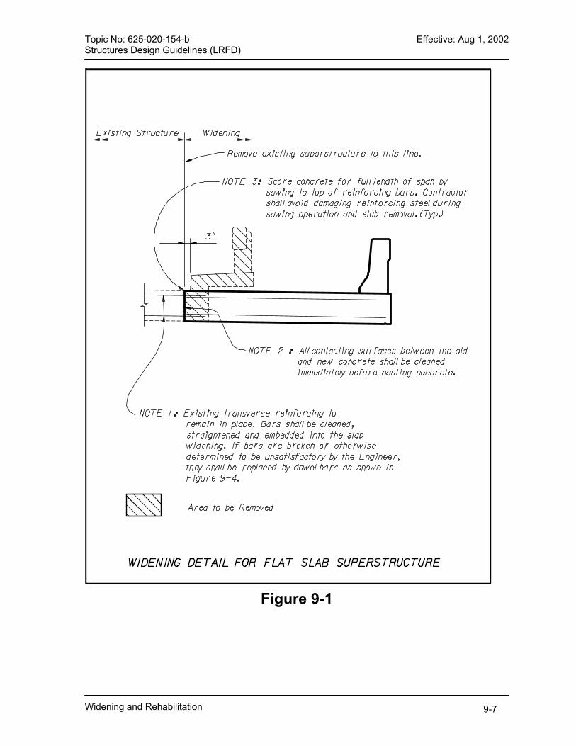
Topic No: 625-020-154-b Effective: Aug 1, 2002 Structures Design Guidelines (LRFD)
Figure 9-1
Widening and Rehabilitation 9-7

Topic No: 625-020-154-b Effective: Aug 1, 2002 Structures Design Guidelines (LRFD)
Figure 9-2
Widening and Rehabilitation 9-8

Topic No: 625-020-154-b Effective: Aug 1, 2002 Structures Design Guidelines (LRFD)
Figure 9-3
Widening and Rehabilitation 9-9

Topic No: 625-020-154-b Effective: Aug 1, 2002 Structures Design Guidelines (LRFD)
Widening and Rehabilitation 9-10
Figure 9-4
Topic No: 625-020-154-b Effective: Aug 1, 2002 Structures Design Guidelines (LRFD)
CHAPTER 10 MOVABLE BRIDGE REQUIREMENTS
10.1 General .........................................................................................................10-1 10.1.1 Applicability .............................................................................................10-1 10.1.2 Redundancy ............................................................................................10-1 10.1.3 Trunnion Support Systems......................................................................10-2 10.1.4 Vertical Clearance Requirements............................................................10-2 10.1.5 Tender Parking........................................................................................10-3 10.1.6 Definitions and Terms .............................................................................10-3 10.1.7 Movable Bridge Terminology...................................................................10-3
10.2 Construction Specifications and Design Calculations ...................................10-3 10.3 Special Strength Load Combination [2.4.2.2]................................................10-4 10.4 Speed Control for Leaf-driving Motors [5.4] ..................................................10-4
10.4.1 Requirements for Mechanical Drive Systems..........................................10-4 10.4.2 Requirements for Hydraulic Drive Systems.............................................10-4
10.5 Machinery Systems.......................................................................................10-4
10.5.1 Trunnions and Trunnion Bearings ...........................................................10-4 10.5.2 Racks and Girders...................................................................................10-5 10.5.3 Span Balance [1.5] ..................................................................................10-5 10.5.4 Speed Reducers......................................................................................10-6 10.5.5 Open Gearing..........................................................................................10-7 10.5.6 Span Locks [6.8.1.5.1].............................................................................10-7 10.5.7 Brakes .....................................................................................................10-8 10.5.8 Couplings ................................................................................................10-8 10.5.9 Clutches ..................................................................................................10-8 10.5.10 Bearings (Sleeve and Anti-Friction).......................................................10-9 10.5.11 Anchors .................................................................................................10-9 10.5.12 Fasteners ............................................................................................ 10-10
10.6 Hydraulic Systems ...................................................................................... 10-12
10.6.1 Hydraulic Pumps ................................................................................... 10-13 10.6.2 Cylinders ............................................................................................... 10-13 10.6.3 Control Components ............................................................................. 10-13 10.6.4 Hydraulic Lines...................................................................................... 10-13 10.6.5 Miscellaneous Hydraulic Components .................................................. 10-14
10.7 Electrical [AASHTO 8]................................................................................. 10-14
10.7.1 Electrical Service [AASHTO 8.1] ...........................................................10-14
Movable Bridge Requirements 10-i
Topic No: 625-020-154-b Effective: Aug 1, 2002 Structures Design Guidelines (LRFD)
10.7.2 Alternating Current Motors [AASHTO 8.5]............................................. 10-15 10.7.3 Engine Generators [AASHTO 8.3.9]...................................................... 10-15 10.7.4 Automatic Transfer Switch [AASHTO 8.3.8].......................................... 10-15 10.7.5 Electrical Control [AASHTO 8.4] ...........................................................10-16 10.7.6 Motor Controls [AASHTO 8.6] ............................................................... 10-16 10.7.7 Programmable Logic Controllers [AASHTO 8.4.2.3] ............................. 10-17 10.7.8 Limit and Seating Switches [AASHTO 8.4.4]......................................... 10-17 10.7.9 Safety Interlocking [AASHTO 8.4.1] ...................................................... 10-24 10.7.10 Instruments [AASHTO 8.4.5]............................................................... 10-24 10.7.11 Control Console [AASHTO 8.4.6] ........................................................ 10-24 10.7.12 Electrical Connections between Fixed and Moving Parts.................... 10-25 10.7.13 Electrical Connections across the Navigable Channel ........................ 10-25 10.7.14 Service Lights...................................................................................... 10-25 10.7.15 Navigation Lights]................................................................................ 10-25 10.7.16 Grounding and Lightning Protection ....................................................10-25 10.7.17 Movable Bridge Traffic Signals and Safety Gates] .............................. 10-26 10.7.18 Communications Systems [N/A] .......................................................... 10-26 10.7.19 Functional Checkout [N/A]................................................................... 10-27
10.8 Control House Architectural Design ............................................................10-30
10.8.1 General ................................................................................................. 10-30 10.8.2 Site Water Lines.................................................................................... 10-31 10.8.3 Site Sanitary Sewage System ............................................................... 10-31 10.8.4 Stairs, Steps and Ladders ..................................................................... 10-31 10.8.5 Handrails and Railing ............................................................................ 10-32 10.8.6 Framing and Sheathing ......................................................................... 10-32 10.8.7 Desktop and Cabinet............................................................................. 10-32 10.8.8 Insulation............................................................................................... 10-32 10.8.9 Fire-Stopping......................................................................................... 10-32 10.8.10 Roof.....................................................................................................10-32 10.8.11 Doors And Hardware........................................................................... 10-33 10.8.12 Windows.............................................................................................. 10-33 10.8.13 Veneer Plaster (Interior Walls) ............................................................10-34 10.8.14 Gypsum Board (Interior Walls) ............................................................10-34 10.8.15 Floor Tile .............................................................................................10-34 10.8.16 Epoxy Flooring .................................................................................... 10-34 10.8.17 Painting ............................................................................................... 10-34 10.8.18 Wall Louvers ....................................................................................... 10-34 10.8.19 Toilet and Bath Accessories................................................................ 10-34 10.8.20 Equipment and Appliances.................................................................. 10-34 10.8.21 Furnishings..........................................................................................10-34 10.8.22 Pipe and Fittings.................................................................................. 10-35 10.8.23 Plumbing Fixtures................................................................................ 10-35 10.8.24 Heating, Ventilating and Air Conditioning ............................................ 10-35 10.8.25 Interior Luminaires............................................................................... 10-35 10.8.26 Video Equipment ................................................................................. 10-35
Movable Bridge Requirements 10-ii

Topic No: 625-020-154-b Effective: Aug 1, 2002 Structures Design Guidelines (LRFD) 10.9 Maintainability ............................................................................................. 10-36
10.9.1 General ................................................................................................. 10-36 10.9.2 Trunnion Bearings ................................................................................. 10-36 10.9.3 Span-Jacking of New Bridges ...............................................................10-36 10.9.4 Trunnion Alignment Features ................................................................ 10-37 10.9.5 Lock Systems........................................................................................ 10-37 10.9.6 Machinery Drive Systems...................................................................... 10-37 10.9.7 Lubrication Provisions ...........................................................................10-37 10.9.8 Drive System Bushings .........................................................................10-38 10.9.9 Local Switching ..................................................................................... 10-38 10.9.10 Service Accessibility............................................................................ 10-38 10.9.11 Service Lighting and Receptacles ....................................................... 10-38 10.9.12 Communications.................................................................................. 10-38 10.9.13 Wiring Diagrams.................................................................................. 10-38 10.9.14 Diagnostic Reference Guide for Maintenance..................................... 10-39 10.9.15 Navigation Lights................................................................................. 10-39 10.9.16 Working Conditions for Improved Maintainability................................. 10-39 10.9.17 Weatherproofing.................................................................................. 10-39
Movable Bridge Requirements 10-iii


Topic No: 625-020-154-b Effective: Aug 1, 2002 Structures Design Guidelines (LRFD)
Chapter 10 MOVABLE BRIDGE REQUIREMENTS
10.1 General
This chapter contains information and criteria related to the design of movable bridge projects. It sets forth the basic Florida Department of Transportation (FDOT) design criteria that are exceptions or additions to those specified in the AASHTO LRFD-Movable Highway Bridge Design Specifications, First Edition, 2000 and any interim releases thereafter and herein referred to as LRFD-MHB Specifications, except English (use soft conversions to convert to English units). Where applicable other sections of this SDG also apply to the design of movable bridges.
10.1.1 Applicability A. The design criteria of this chapter are applicable for new bridges and the
electrical/machinery design for rehabilitation of existing bridges. The requirements for structural rehabilitation will be determined on a bridge-by-bridge basis, based on evaluations during the BDR phase and approval by the Structures Design Office (SDO). Projects for which the criteria are applicable shall result in designs that: 1.) Preferably, provide new bascule bridges with two leafs per span
configuration.
Commentary: Single leaf bascules are discouraged, but may be considered for small channel openings where navigational and vehicular traffic is low. Assure reliable operation of movable bridges through redundancy features in drive and control systems, for both new and rehabilitation projects.
B. Specific practices required by the Department in considering the applicability and requirements of bascule bridges: 1.) Examine and evaluate alternative bridge configurations offering favorable life
cycle cost benefits. C. Consider improved design or operational characteristics providing advantage to
the traveling public. 1.) Incorporate design and operational features which are constructible and
which can be operated and maintained by the Department's forces. 2.) Maintain consistency of configuration, when feasible, for movable bridges
throughout the State.
10.1.2 Redundancy Include recommendations for redundant drives and control systems in the BDR/30% plans submittal. For bridges having low rates of anticipated bridge openings or
Movable Bridge Requirements 10-1

Topic No: 625-020-154-b Effective: Aug 1, 2002 Structures Design Guidelines (LRFD) average daily traffic, application of redundant drive and control systems may not be cost effective. In this event, submit such information in the BDR and provide appropriate recommendations for omission of redundant systems. Commentary: Redundant drive configurations include: A. Hydraulic drive systems operated by multiple hydraulic cylinders. In these
systems, a pump drive motor or its hydraulic pump can be isolated and bridge operations can continue while repairs are accomplished.
B. Gear driven systems that may be driven through one gear train into a single rack of a two-rack bridge.
Provide two rack drives actuated by dual motor drive systems either of which will be capable of operating the bridge leaf. Normal operation of this configuration will involve operation of one drive/motor system. Provide an alternator to alternate drives/motors for each opening. Design hydraulic cylinder actuated movable bridges to function in spite of loss of a main pump motor, hydraulic pump, or drive cylinder. Design the system to include all necessary valving, piping, etc., to permit safe and expeditious changeover to the redundant mode. Specify a permanent plaque displayed in a convenient location on the machinery platform describing actions (valve closures and openings, electrical device deactivation, etc.) necessary for operation in the redundant mode. When operating with either a single rack drive functioning or unsymmetrical hydraulic cylinder forces applied to the leaf, design the structure for Movable Bridge - Specific load combinations, strength BV-I and BV-II. Reduce the load factors for strength BV-I to 1.35 [Table 2.4.2.3-1].
10.1.3 Trunnion Support Systems Provide trunnion support systems as follows: A. Simple, rotating trunnion configuration, with bearing supports, on towers, on both
inboard and outboard sides of the trunnion girder. B. Sleeve bearings should be considered for only small bascule bridges and must
be approved by the SDO at the BDR phase. Design constraints and cost justification must be provided.
C. Design trunnion supports on each side of the main girder with similar stiffness vertically and horizontally.
10.1.4 Vertical Clearance Requirements Design bascule leaf for unlimited vertical clearance between the fenders in the full open position. Any encroachment of the leaf into the horizontal clearance zone must receive favorable Coast Guard review prior to approval of the BDR.
Movable Bridge Requirements 10-2
Topic No: 625-020-154-b Effective: Aug 1, 2002 Structures Design Guidelines (LRFD) 10.1.5 Tender Parking Provide two parking spaces for bridge tenders in all new bridge designs, preferably on the tender house side of the bridge.
10.1.6 Definitions and Terms A. Auxiliary Drive: Hand crank, gearmotor with disconnect-type coupling, portable
hydraulic pump, drill, etc., that can be used to lower leaf(s) for vehicular traffic or raise the leaf(s) for marine traffic if the main drives fail.
B. Creep Speed: Not more than 10% of full speed, final creep speed will be determined by bridge conditions.
C. Emergency Stop: Leaf(s) stop within (3±1) seconds of depressing the EMERGENCY STOP push-button or in the event of a power failure. All other rotating machinery stops instantly.
D. End-of-Travel Function: Contact connection where a closed contact allows operation and an open contact stops operation (i.e., leaf limit switches).
E. Fully Seated: Leaf(s) is(are) at rest on live load shoes, interlock OK to drive span locks.
F. Fully Open: Tip of leaf clears fender of a vertical line as defined by Coast Guard. G. Hard Open: Leaf opening such that counterweight bumper blocks come in contact
with pier bumper blocks. H. Indicating Function: Contact connection where a closed contact indicates
operation and an open contact indicates no operation (i.e., indicating lights). I. Interlocks or Safety Interlocks: Ensure events occur in sequence and no out-of-
sequence events can occur. J. Mid-Cycle Stop: Leaf(s) stop following normal ramping after depressing the STOP
push-button when in the middle of an opening or closing cycle. K. Near Closed: A point 8 to 10 degrees (approximately, final position to be field
determined) before FULL CLOSED, drive to creep speed. L. Near Open: A point 8 to 10 degrees (approximately, final position to be field
determined) before FULL OPEN, drive to creep speed. M. Ramp: Rate of acceleration or deceleration of leaf drive.
10.1.7 Movable Bridge Terminology See Figure 10-2 for standard bridge terminology.
10.2 Construction Specifications and Design Calculations
Use the FDOT’s Standard Specifications for Road and Bridge Construction and the “Technical Special Provisions” issued by the Mechanical/Electrical Section of the SDO. Additional specifications may be required. Provide detailed calculations to justify all equipment and systems proposed. Submit calculations, for review, for all aspects of the systems and components. Substantiate recommended equipment and sizes. Submit calculations in an 8 ½ x 11 inch binder.
Movable Bridge Requirements 10-3

Topic No: 625-020-154-b Effective: Aug 1, 2002 Structures Design Guidelines (LRFD) 10.3 Special Strength Load Combination [2.4.2.2]
Evaluate the following owner-specified special design vehicle for Strength II Load Combination of the LRFD Specification as follows: Apply the full HL-93 loading to the design of the cantilever girders for bascule bridges, assuming the span locks are not engaged to transmit live load to the opposite leaf.
10.4 Speed Control for Leaf-driving Motors [5.4]
Design a drive system that is capable of operating the leaf in no more than 70 seconds (See Figure 10-1) under normal conditions. Clearly indicate on the plans the following required torques: A. TA - the maximum torque required to accelerate the leaf to meet the required time
of operation. B. TS - the maximum torque required for starting the leaf. C. TCV - the maximum torque required for constant velocity.
10.4.1 Requirements for Mechanical Drive Systems Specify a drive capable of developing the torques stated above and operating the leaf (at full speed) in the 70 seconds time limit stated above. Compute the acceleration torque for the inertia and the loading specified for the maximum constant velocity torque [5.4.2]. In addition the drive must be capable of holding the leaf (zero speed) for the required maximum staring torque [5.4.2].
10.4.2 Requirements for Hydraulic Drive Systems Design a drive capable of developing the acceleration torque required for the inertia and the loading specified for the maximum constant velocity torque [5.4.2] and operating the leaf at full speed in the 70 seconds time limit stated above. Longer operating times are allowed for operation under abnormal conditions. Do not exceed 130 seconds under any condition.
10.5 Machinery Systems
10.5.1 Trunnions and Trunnion Bearings A. Trunnions:
1.) Provide all shoulders with fillets of appropriate radius. Provide suitable provisions for expansion between shoulders and bearings.
2.) For keys and keyways see 6.7.8 and 6.7.10 of the AASHTO Specification. 3.) Do not use keyways between the trunnion and the trunnion hub/collar. 4.) For trunnions over 8 inch diameter, provide a hole 1/5 the trunnion diameter
lengthwise through the center of the trunnion. Extend the trunnion at least 5/8 inch beyond the end of the trunnion bearings. Provide a 2 inch long counterbore concentric with the trunnion journals at each of the hollow trunnion ends.
Movable Bridge Requirements 10-4
Topic No: 625-020-154-b Effective: Aug 1, 2002 Structures Design Guidelines (LRFD)
5.) In addition to the shrink fit, drill dowels of appropriate size through the hub into the trunnion after the trunnion is in place.
6.) When anti-friction roller bearings are used, the surface finish must be compatible with the bearing manufacturer’s requirements. Deflections of the trunnion with load must be calculated and compared with these clearances to insure the journals do not bottom out and bind, particularly on rehabilitations and Hopkins frame bridges. Clearances may have to be adjusted.
7.) For rehabilitation of existing Hopkins trunnions, verify that trunnion eccentrics have capability for adjustment to accommodate required changes in trunnion alignment. If not, provide repair recommendations.
8.) If Hopkins trunnions are used, design three-piece eccentric assembly. B. Hubs and Rings:
1.) Provide hubs and Rings with a mechanical shrink fit. 2.) See Figure 10-3, for minimum requirements.
10.5.2 Racks and Girders Detail a mechanical, bolted connection between the rack and girder. Specify a machined finish for the connecting surfaces.
10.5.3 Span Balance [1.5] A. New Construction:
1.) Design new bascule bridges such that the center of gravity may be adjusted vertically and horizontally.
2.) Design mechanical drive system bridges such that the center of gravity is forward (leaf heavy) of the trunnion or located at an angle (α) 30° to 50° above a horizontal line passing through the center of trunnion with the leaf in the down position. This will result in the leaf being tail (counterweight) heavy in the fully open position and leaf heavy in the fully closed position.
3.) Design hydraulic drive systems bridges such that the center of gravity is forward (leaf heavy) of the trunnion throughout the operating (opening) angle.
4.) Design both single and double leaf bascule for a leaf heavy out of balance condition which will produce an equivalent leaf reaction of 2 kips minimum) when the leaf is down. Design the live load shoe to resist this equivalent leaf reaction.
B. Rehabilitation Projects: Apply the above provisions for bridge rehabilitations in which the leaf balance must be adjusted. Include detailed leaf balance adjustment plans, including the location and weight of any ballast to be furnished and installed to achieve an acceptable balance condition.
C. Design Unbalance: For new and rehabilitated bridges, state the design unbalance in the plans using "W", "L" and "α". Where: α = angle of inclination of the center of gravity above a horizontal line through the trunnion when the leaf is closed.
Movable Bridge Requirements 10-5

Topic No: 625-020-154-b Effective: Aug 1, 2002 Structures Design Guidelines (LRFD)
W = total weight of the leaf. L = distance from the trunnion axis to the leaf center of gravity.
10.5.4 Speed Reducers Specify and detail speed reducers to meet the requirements of the latest edition of ANSI/AGMA 6010 Standard for Spur, Helical, Herringbone, and Bevel Enclosed Drives. Specify and detail gearing to conform to AGMA Quality No. 8 or higher using following factors: A. Service Factor of 1.0 or higher indicating “Actual Input” and “Output Torque”
requirements. B. Cm and Km = per the current AGMA 6010 Standard. C. Ca and Ka = 1.0 D. Cl and KI = 1.0 E. Cr and Kr = 1.0 A reverse bending factor of 0.8 is required in the strength rating (not required for vertical lift drives). Allowable contact stress numbers, "Sac," shall conform to the current AGMA 6010 Standard for through hardened and for casehardened gears. Allowable bending stress numbers, "Sat," shall conform to the current AGMA 6010 Standard for through-hardened and for case-hardened gears. Commentary: These allowable contact and bending stress numbers are for AGMA Grade 1 materials. Grade 2 allowables are permitted only with an approved verification procedure and a sample inspection as required per Mechanical/Electrical Section of the SDO instructions. All speed reducers on a bridge should be models from one manufacturer unless otherwise approved by the Mechanical/Electrical Section of the SDO. Include gear ratios, dimensions, construction details, and AGMA ratings on the Drawings. Provide a reducer capable of withstanding an overload torque of 300% of full-load motor torque. This torque shall be greater than the maximum holding torque for the span under the maximum brake-loading conditions. Specify gears with spur, helical, or herringbone teeth. Bearings shall be anti-friction type and shall have a L-10 life of 40,000 hours as defined in AASHTO, except where rehabilitation of existing boxes requires sleeve-type bearings. Housings shall be welded steel plate or steel castings. The inside of the housings shall be sandblast-cleaned prior to assembly, completely flushed, and be protected from rusting. Specify exact ratios.
Movable Bridge Requirements 10-6
Topic No: 625-020-154-b Effective: Aug 1, 2002 Structures Design Guidelines (LRFD) Specify units with means for filling and completely draining the case, that have an inspection cover to permit viewing of all gearing (except the differential gears, if impractical), and both a dipstick and sight glass to show the oil level. Sight glasses shall be of rugged construction and protected against breakage. Specify drains with shutoff valves to minimize spillage. Furnish each unit with a moisture trap breather of the desiccant type with color indicator to show desiccant moisture state. Specify splash lubrication on the gears and bearings, unless otherwise required by the gear manufacturer. Do not specify pressurized lubrication systems on speed reducer boxes unless approved in writing by the Mechanical/Electrical Section of the SDO. Provide remote indication of pressurized lubrication system malfunction. Commentary: If a pressurized lubrication system is specified for the reducer, a redundant lubrication system shall also be specified. The redundant system shall operate at all times when the primary system is functioning.
10.5.5 Open Gearing Limit the use of open gearing. When used, design open gearing per AGMA specifications. Design and specify guards for high-speed gearing.
10.5.6 Span Locks [6.8.1.5.1] A. General:
1.) Design span locks attached to the main bascule girders, if possible, giving consideration to maintenance access.
2.) Specify a 4 x 6 inch minimum rectangular lock bars, unless analysis shows need for a larger size. Submit design calculations and the selection criteria for review and approval.
3.) Install the bar in the guides and receivers with bronze wear fittings top and bottom, properly guided and shimmed. Provide lubrication at the sliding surfaces. Both the front and rear guides are to have a “U” shaped wear-plate that restrains the bar sideways as well as vertically. The receiver is to have a flat wear-plate to give freedom horizontally to easily insert the lock-bar in the opposite span. The total vertical clearance between the bar and the wear-shoes shall be 0.010 to 0.025 inches. Specify the total horizontal clearance on the guides to be 1/16 ±1/32 inches.
4.) Provide adequate stiffening behind the web for support of guides and receivers.
5.) Mount guides and receivers with ½ inch minimum shims for adjusting. Slot wear-plate shims for insertion and removal.
6.) Provide lubrication fittings at that are convenient for routine maintenance. 7.) Mount actuation elements on the lock to activate limit switches to control
each end of the stroke. Incorporate a means to adjust the limit switch actuation. Taper the receiver end of the lock-bar to facilitate insertion into the receivers of the opposite span.
Movable Bridge Requirements 10-7
Topic No: 625-020-154-b Effective: Aug 1, 2002 Structures Design Guidelines (LRFD)
8.) Connection of the lock-bar to the hydraulic cylinder shall allow for the continual vibration due to traffic on the leaf. This may be accomplished by providing self-aligning rod-end couplers or cylinders with elongated pinholes on male clevises.
9.) The hydraulic fluid system is to be a reversing motor-driven pump and piping system connected to the cylinder. Specify relief valves to prevent over pressure should the lock-bar jam. Specify pilot operated check valves in the lines to the cylinder to lock the cylinder piston in place when pressure is removed. Provide a hydraulic hand pump and quick-disconnect fittings on the piping to allow pulling or driving of the lock-bar on loss of power. Specify the time of driving or pulling the bar at 5 to 9 seconds.
10.) Design and specify access platforms with access hatches located out of the travel lanes.
B. Lock Design Standards: 1.) The empirical formula, Equation 10-1 listed below, can be used to determine
double leaf bascule lock loads with acceptable results; however, more exact elastic analysis can be used if the solution thus obtained is not accurate enough.
a. Where:
( ) ( )LALAPS −= 34
2 [Eq. 10-1]
S = Shear in lock in kips for a given load on the span, “P.” A = Distance in feet from the support to the given load, “P.” L = Distance in feet from the support to the center lock.
b. See Figure 10-4 for diagrammatic sketch of “S,” “A,” and “L.” c. Double the Dynamic Load Allowance (IM) to 66% for lock design.
2.) Use a Dynamic Load Allowance of 100% for Lock Design on a double-leaf bascule span expected to carry traffic with ADTT (Average Daily Truck Traffic) > 2500.
10.5.7 Brakes Use thrustor type brakes. Provide a machinery brake and a motor brake. Submit calculations justifying the brake torque requirements. Show brake torque requirements on plans. Carefully consider machinery layout when locating brakes. Avoid layouts that require removal of multiple pieces of equipment for maintenance of individual components.
10.5.8 Couplings Submit calculations and manufacturer’s literature for coupling sizes specified. Provide coupling schedule on plans.
10.5.9 Clutches Rate clutches for emergency drive engagement for the maximum emergency drive torque. The engaging mechanism shall be positive in action and shall be designed to
Movable Bridge Requirements 10-8
Topic No: 625-020-154-b Effective: Aug 1, 2002 Structures Design Guidelines (LRFD) remain engaged or disengaged while rotating at normal operating speed. Provisions shall be made so that the main operating drive is fully electrically disengaged when the clutch is engaged.
10.5.10 Bearings (Sleeve and Anti-Friction) A. Sleeve Bearings shall be grease-lubricated bronze bushings 8 inches in diameter
or less and shall have grease grooves cut in a spiral pattern for the full length of the bearings.
B. Anti-Friction Bearing pillow block and flange-mounted roller bearings shall be adaptor mounting, self-aligning, expansion and/or non-expansion types. Housings shall be cast steel and capable of withstanding the design radial load in any direction, including uplift. The same supplier as the bearing shall furnish housing. Specify bases cast without mounting holes. Mounting holes shall be “drilled-to-fit” at the site at the time of assembly with the supporting steel work. Seals shall retain the lubricant and exclude water and debris. Cap bolts on pillow blocks shall be high-strength steel. The cap and cap bolts shall be capable of resisting the rated bearing load as an uplift force. Where clearance or slotted holes are used, the clearance space shall be filled with a non-shrink grout after alignment to insure satisfactory side load performance.
10.5.11 Anchors For machinery supports anchored to concrete, design for the maximum forces generated in starting or stopping the leaf plus 100% impact. Design hydraulic cylinder supports for 150% of the relief valve setting or the maximum operating loads plus 100% impact, whichever is greater. Detail machinery supports anchored to the concrete by preloaded anchors such that no tension occurs at the interface of the steel and concrete under any load conditions. Mechanical devices used as anchors shall be capable of developing the strength of reinforcement without damage to the concrete. All concrete anchors shall be undercut bearing, expansion-type anchors. The anchorage shall be developed by expanding an anchor sleeve into a conical undercut so as to eliminate direct lateral stresses found in the setting of conventional anchors. The expansion anchors shall meet the ductile failure criteria of American Concrete Institute (ACI) Standard 349, Appendix B. Design an expansion anchoring system that can develop the tensile capacity of the bolt without slip or concrete failure. The bolt shall consistently develop the minimum specified strength of the bolting material to provide a favorable plastic stretch over the length of the bolt prior to causing high-energy failure. Require pullout testing of anchors deemed to be critical to the safe operation of the bridge machinery system. Pullout verification tests shall be performed at not less than 200% of maximum operational force levels. Design the conical undercut and the nut to transfer the bolt tension load into direct bearing stress between the conical nut and expansion sleeve and the expansion sleeve and conical concrete surface. The depth and diameter of the embedment
Movable Bridge Requirements 10-9

Topic No: 625-020-154-b Effective: Aug 1, 2002 Structures Design Guidelines (LRFD) shall be sufficient to assure steel failure, with concrete cone shear strength greater than the strength of the bolting material. A. Anchor Bolt Design:
1.) Design anchor bolts subject to tension at 200% of the allowable basic stress and shown, by tests, to be capable of developing the strength of the bolt material without damage to concrete.
2.) The design strength of embedment is based on the following maximum steel stresses:
a.) Tension, fsmax = 0.9fy b.) Compression and Bending, fsmax = 0.9fy c.) Shear, fsmax = 0.55fy (shear-friction provisions of ACI, Section 11.7, shall
apply) d.) The permissible design strength for the expansion anchor steel is reduced
to 90% of the values for embedment steel. e.) For bolts and studs, the area of steel required for tension and shear based
on the embedment criteria shall be considered additive. f.) Calculate the design pullout strength of concrete, Pc, in pounds, as:
[Eq. 10-2]AfP cc '96.3 φ=
g.) Where:
Ø = Capacity reduction factor, 0.65 A = Projected effective area of the failure cone, in² ƒ′c = Specified compressive strength of concrete, psi Steel strength controls when the design pullout strength of the concrete, Pc, exceeds the minimum ultimate tensile strength of the bolt material. The effective stress area is defined by the projected area of the stress cone radiating toward the concrete surface from the innermost expansion contact surface between the expansion anchor and the drilled hole. The effective area shall be limited by overlapping stress cones, by the intersection of the cones with concrete surfaces, by the bearing area of anchor heads, and by the overall thickness of the concrete. The design pullout strength of concrete shall be equal to or greater than the minimum specified tensile strength (or average tensile strength if the minimum is not defined) for the bolting material.
10.5.12 Fasteners A. All bolts for connecting machinery parts to each other and to supporting
members shall be as shown on the plans or specified otherwise and conform to one of the following types:
1.) High-strength bolts. 2.) Turned bolts, turned cap screws, and turned studs.
Movable Bridge Requirements 10-10
Topic No: 625-020-154-b Effective: Aug 1, 2002 Structures Design Guidelines (LRFD)
3.) High-strength turned bolts, turned cap screws, and turned studs. B. High strength bolts shall meet the requirements of ASTM A325. High strength
bolts shall have regular hexagonal heads. Holes for high-strength bolts shall be no more than 0.010 inch [0.25 mm] larger than the actual diameter of individual bolts and drilling holes to match the tolerances for each bolt. The clearance shall be checked with 0.011-inch [0.28 mm] wire. The hole shall be considered too large if the wire can be inserted in the hole together with the bolt. Install, wherever possible, high-strength bolts connecting machinery components to structural elements or to other machinery components comprised of different thicknesses such that the bolt head is adjacent to the connected element with the least thickness.
C. Turned bolts, turned cap screws, and turned studs shall have turned shanks and cut threads. Turned bolts shall have semi-finished, washer-faced, hexagonal heads and nuts. All finished shanks of turned fasteners shall be 0.06 inches [1.6 mm] larger in diameter than the diameter of the thread, which shall determine the head and nut dimensions.
D. Drill or ream-assemble all elements connected by bolts to assure accurate alignment of the hole and accurate clearance over the entire length of the bolt within the specified limits.
E. Provide bolt heads, nuts, castle nuts, and hexagonal head cap screws dimensioned in accordance with ANSI Standard B18.2.3, Hexagon Bolts and ANSI Standard B18.2.4.6 Nuts.
F. Provide heavy series heads and nuts for turned bolts, screws, and studs. G. ASTM A325 bolts shall have regular hex heads. H. The dimensions of socket-head cap screws, socket flathead cap screws, and
socket-set screws shall conform to ANSI Standard B18.3.1. Provide screws made of heat-treated alloy steel, cadmium-plated, and furnished with a self-locking nylon pellet embedded in the threaded section. Unless otherwise called for on the plans or specified herein, provide setscrews of the headless safety type with threads of coarse thread series and cup points. Do not use setscrews to transmit torsion nor as the fastening or stop for any equipment that contributes to the stability or operation of the bridge.
I. Threads for cap screws shall conform to the coarse thread series and shall have a Class 6g tolerance. For bolts and nuts, the bolt shall conform to the coarse thread series and shall have a Class 6g tolerance. The nut shall have a Class 6H in accordance with the ANSI Standard B18.2.6 Screw Threads [ANSI Standard B18.2.6M Metric Screw Threads].
J. Spotface bolt holes through unfinished surfaces. Insure the head and nut are square with the axis of the hole.
K. Unless otherwise called for, sub drill all bolt holes in machinery parts or connecting these parts to the supporting steel work at least 0.03 in [0.80 mm] smaller in diameter than the bolt diameter. Ream for the proper fit at assembly or at erection with the steel work after the parts are correctly assembled and aligned.
L. Ream or drill holes in shims and fills for machinery parts to the same tolerances as the connected parts at final assembly.
Movable Bridge Requirements 10-11

Topic No: 625-020-154-b Effective: Aug 1, 2002 Structures Design Guidelines (LRFD) M. Furnish positive locks of an approved type for all nuts except those on ASTM
A325 Bolts. If double nuts are used, they shall be used for all connections requiring occasional opening or adjustment. Provide lock washers made of tempered steel if used for securing.
N. Install high-Strength bolts with a hardened plain washer meeting ASTM F436 at each end.
O. Wherever possible, insert high strength bolts connecting machinery parts to structural parts or other machinery parts through the thinner element into the thicker element.
P. Provide cotters that conform to SAE standard dimensions and are made of half-round stainless steel wire, ASTM A276, Type 316.
Q. Anchor bolts connecting machinery parts to masonry shall be ASTM A325 material, hot-dipped galvanized per ASTM A153 unless otherwise approved by the Engineer. Show bolts on the masonry drawings. Anchor bolts for new construction shall be cast in place and not drilled. The material and loading requirements shall be as shown on the plans. The filler material may be a non-shrink grout, Babbitt metal, or zinc.
R. All fasteners shall be of United States manufacture and shall be clearly marked with the manufacturer’s designation.
10.6 Hydraulic Systems
Perform complete analysis and design of hydraulic systems utilized for leaf drive and control, including evaluation of pressure drops throughout the circuit for all loading conditions. Calculate pressure drops for all components of their circuits including valves, filters, hoses, piping, manifolds, flow meters, fittings, etc. Power requirements shall be determined based upon pressure drops at the required flows and conservative pump efficiency values. Design the system so that normal operating pressure is limited to 2500 psi. During short periods of time in emergency operations, pressure can increase to 3000 psi, maximum. Correlate hydraulic system strength calculations with the structure loading analysis. Design the power unit and driving units for redundant operation so that the bridge leaf (s) may be operated at a reduced speed with one power unit or one driving unit out of service. Design the power unit to permit its installation and removal in the bridge without removing any major components. Design the power unit to allow the removal of each pump, motor, filter, and main directional valves without prior removal of any other main components. Operation of the redundant components shall be possible with the failed component removed from the system. Design all span operating hydraulic components within the pier enclosure to prevent any escape of oil to the environment. Specify a drip pan extending beyond the outermost components of the power unit and flange connections to prevent spilling oil leakage on the machinery room floor. Specify sump pumps and other clean up devices suitable for safe collecting and removing of any spilled oil.
Movable Bridge Requirements 10-12

Topic No: 625-020-154-b Effective: Aug 1, 2002 Structures Design Guidelines (LRFD) Design the hydraulic system to limit the normal operating oil temperature to 170° F during the most adverse ambient temperature conditions anticipated.
10.6.1 Hydraulic Pumps Specify minimum pressure rating of pumps to be 1.5 times the maximum operating pressure. Specify pumps of the Pressure Compensated type. Variation of the pressure setting, including ±50 cst viscosity change shall be ±2.5% maximum. Overall minimum efficiency shall be 0.86. Boost pumps of any power, and auxiliary or secondary pumps less than 5 hp [3.7 kW], need not be pressure compensated.
10.6.2 Cylinders Design the hydraulic cylinder drive systems to prevent sudden closure of valving, and subsequent sudden locking of cylinders, in the event of a power failure or emergency stop. Specify cylinders designed according to ASME Pressure Vessel Code, Section 8. Specify cylinders with a minimum theoretical static failure pressure rating of 11 (10,000 psi) as defined by NFPA Standards; and designed to operate on biodegradable-based hydraulic fluid unless otherwise approved by the Mechanical/Electrical Section of the SDO. Specify stainless steel rods with chrome plated finish 0.005 to 0.012 inches thick per QQ-C-320C, Class 2a or others as approved by the Mechanical/Electrical Section of the SDO. The main lift cylinders shall be provided with pilot operating counterbalance or other load protection valves. They shall be manifolded directly to ports of cylinder barrel and hold load in position if supply hoses leak or fail.
10.6.3 Control Components A. Flow Control Valves: Use of non-compensated flow control valves shall be
limited to applications where feed rates are not critical and where load induced pressure is relatively constant. Where load induced pressure is variable, specify pressure compensated flow control valves.
B. Directional Valves: Vertical mounting of solenoid Directional Valves where solenoids are hanging from the valve is to be avoided; horizontal mounting is recommended. Solenoid operated directional control valves provided with a drain connection to reduce response times must always be mounted horizontally.
C. Relief Valves: Specify relief valves to protect all high-pressure lines. D. Check Valves: Specify poppet type check valves on main circuits or located to
hold loads.
10.6.4 Hydraulic Lines A. Piping: Specify stainless steel piping material conforming to ASTM A312 GRTP
304L or TP316L. For pipe, tubing, and fittings, the minimum ratio of burst pressure rating divided by design pressure in the line shall be 4. Provide
Movable Bridge Requirements 10-13
Topic No: 625-020-154-b Effective: Aug 1, 2002 Structures Design Guidelines (LRFD)
calculations indicating that the velocity of fluid is at or below 4.3 ft/s in suction lines, 6.5 ft/s in return lines, and 21.5 ft/s in pressure lines.
B. Manifolds: Specify the use of manifolded components. C. Flexible Hose: Specify flexible hose only in cases where motion or vibration
makes the use of rigid piping undesirable. Insure that the minimum ratio of burst pressure rating divided by design pressure in the line is 4.
D. Seals: Specify all seals, including the ones installed inside hydraulic components, to be fully compatible with the hydraulic fluid being used and adequate for the maximum pressure and temperature operating at that point.
10.6.5 Miscellaneous Hydraulic Components A. Receivers (Reservoirs): Tanks in open-loop systems shall have a capacity
greater than the maximum flow of three minutes operation of all pumps connected to the tank plus 10%, and/or the capacity of the total oil volume in the system. Tanks must have an adequate heat dissipation capacity to prevent temperatures above 170° F. Tanks in closed-loop hydrostatic systems shall circulate, filter, and cool enough oil to maintain a maximum oil temperature of 170° F. Specify suction port strainers with oil shut-off valves. Specify tanks with easy drainage and provided with adequate openings that allow easy cleaning of all surfaces from the inside. Specify sumps with magnetic traps to capture metal particles. Specify Stainless Steel ASTM A316L tank material. Specify the use of air bladders to avoid water contamination from air moisture condensation due to the breathing effect of the tank.
B. Filtration: Design and specify a filtering system so that filters can be easily serviced and filter elements can be changed without disturbing the system. Do not specify valves that can be left accidentally closed. Strainers are allowed in the suction lines between the tank and the main pumps. Filters can be used if the system is designed to assure that there will be enough static head under all operating conditions at the pumps’ inlets. Require absolute pressure (vacuum) sensors to stop the pumps if adequate suction head is not available at the pumps’ inlets, and specify pressure line filters capable of at least 10-micron filtration between the pump outlet and the rest of the hydraulic system. The system shall have filters with relief-check, by-pass valve and visual clogged filter indicators. Specify a remote sensing pressure switch to indicate a clogged filter. The relief-check, bypass-valve lines must also be filtered.
C. Hydraulic Fluids: Insure that the manufacturers of the major hydraulic components used in the bridge approve the hydraulic fluid specified for use.
10.7 Electrical [AASHTO 8]
10.7.1 Electrical Service [AASHTO 8.1] Wherever possible, design bridge electrical service for 277/480 V, three-phase, "wye." Voltage drop from point of service to furthest load shall not exceed 5%. Do not apply a diversity factor when calculating loads.
Movable Bridge Requirements 10-14
Topic No: 625-020-154-b Effective: Aug 1, 2002 Structures Design Guidelines (LRFD) 10.7.2 Alternating Current Motors [AASHTO 8.5] Size and select motors per AASHTO requirements. On hydraulic systems provide 25% spare motor capacity. Specify motors that comply with the following requirements: A. Design Criteria For Start-Ups: 12 per hour, 2 per ten-minute period. B. Power Output, Locked Rotor Torque, Breakdown or Pullout Torque: NEMA
Design B Characteristics. C. Testing Procedure: ANSI/IEEE 112, Test Method B. Load test motors to
determine freedom from electrical or mechanical defects and compliance with performance data.
D. Motor Frames: NEMA Standard T-frames of steel or cast iron (no aluminum frames allowed) with end brackets of cast iron with steel inserts. Motors 10 Hp [7.5 kW] and larger shall be TEFC.
E. Thermistor System (Motor Sizes 25 Hp [19 kW] and Larger): Three PTC thermistors embedded in motor windings and epoxy encapsulated solid-state control relay for wiring into motor starter.
F. Bearings: Grease-lubricated, anti-friction ball bearings with housings equipped with plugged provision for relubrication, rated for minimum AFBMA 9, L-10 life of 20,000 hours. Calculate bearing load with NEMA minimum V-belt pulley with belt centerline at end of NEMA standard shaft extension. Stamp bearing sizes on nameplate.
G. Nominal Efficiency: Meet or exceed values in ANSI Schedules at full load and rated voltage when tested in accordance with ANSI/IEEE 112.
H. Nominal Power Factor: Meet or exceed values in ANSI Schedules at full load and rated voltage when tested in accordance with ANSI/IEEE 112.
I. Insulation System: NEMA Class F or better. J. Service Factor: 1.15 (except when calculating motor size, use 1.0).
10.7.3 Engine Generators [AASHTO 8.3.9] Design per the requirements of the latest edition of NFPA 110. Size generators so that one side of the channel (one side of the bridge) can be opened at a time concurrent with traffic lights, navigation lights, tender house air conditioners, and house lights. Specify only diesel-fueled generators. Provide fuel tank sized to hold enough fuel to run the generator, at 100% load, for 12 hours (minimum 50 gallons). Specify day tank with a minimum 10-gallon capacity. Do not use the day tank capacity as part of the main tank capacity. Submit calculations justifying generator size recommended.
10.7.4 Automatic Transfer Switch [AASHTO 8.3.8] Design switch in conformance with the requirements of the latest edition of NFPA 110.
Movable Bridge Requirements 10-15
Topic No: 625-020-154-b Effective: Aug 1, 2002 Structures Design Guidelines (LRFD) Specify Automatic Transfer Switch with engine generator. Specify an Automatic Transfer Switch that is fully rated to protect all types of loads, inductive and resistive, from loss of continuity of power, without de-rating, either open or enclosed. Specify withstand, closing, and interrupting ratings sufficient for voltage of the system and the available short circuit at the point of application on the drawings. Provide short circuit calculations to justify ATS proposed.
10.7.5 Electrical Control [AASHTO 8.4] Design an integrated control system. Develop a control interface that matches the operating needs and skill levels of the bridge tenders and maintenance personnel that will be using the system. Design a system configuration, select control devices, and program the Programmable Logic Controller (PLC) to produce the desired interface that will comply with the “Operation Sequence” furnished by the Mechanical/Electrical Section of the SDO. Design the bridge control system to be powered through an uninterruptible power supply. EMERGENCY-STOP (E-STOP) stops all machinery in the quickest possible time but in no less than 3 seconds main drives only. In an emergency, hit this button to stop machinery and prevent damage or injury. Specify a button that is reset by twisting clockwise (or counterclockwise) to release to normal up position. At a minimum, provide alarms for the following events: A. All bridge control failures. B. All generator/Automatic Transfer Switch failures. C. All traffic signal failures. D. All navigation light failures. E. All traffic gate failures. F. All span-lock failures. G. All brake failures (if applicable). H. All leaf limit switch failures. I. All drive failures; including motor high temperature (motors larger than 25 Hp)
and all hydraulic system failures. J. Near and far-leaf total openings (not an alarm but part of the monitoring
function). K. All uses of bypass functions, type and time (not an alarm but part of the
monitoring function).
10.7.6 Motor Controls [AASHTO 8.6] Specify full-size NEMA rated starters. Do not use IEC starters unless space constraints require their use, and then, only by obtaining prior approval from the Mechanical/Electrical Section of the SDO.
Movable Bridge Requirements 10-16
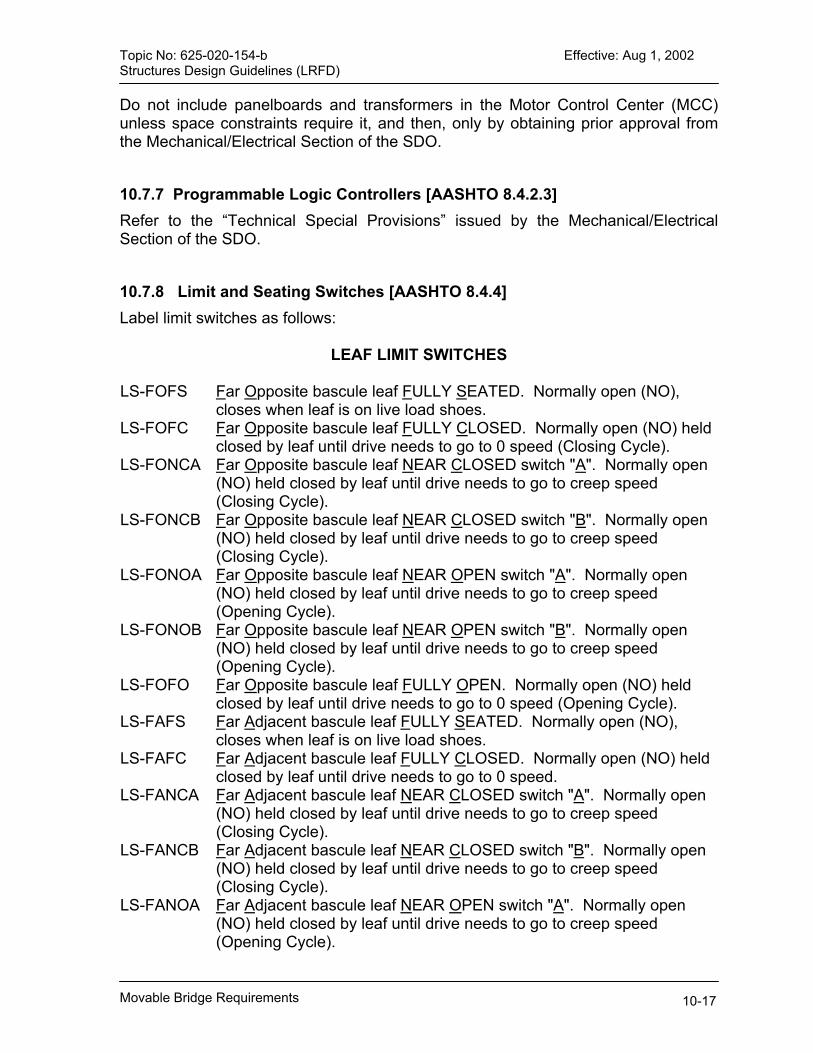
Topic No: 625-020-154-b Effective: Aug 1, 2002 Structures Design Guidelines (LRFD) Do not include panelboards and transformers in the Motor Control Center (MCC) unless space constraints require it, and then, only by obtaining prior approval from the Mechanical/Electrical Section of the SDO.
10.7.7 Programmable Logic Controllers [AASHTO 8.4.2.3] Refer to the “Technical Special Provisions” issued by the Mechanical/Electrical Section of the SDO.
10.7.8 Limit and Seating Switches [AASHTO 8.4.4] Label limit switches as follows:
LEAF LIMIT SWITCHES LS-FOFS Far Opposite bascule leaf FULLY SEATED. Normally open (NO),
closes when leaf is on live load shoes. LS-FOFC Far Opposite bascule leaf FULLY CLOSED. Normally open (NO) held
closed by leaf until drive needs to go to 0 speed (Closing Cycle). LS-FONCA Far Opposite bascule leaf NEAR CLOSED switch "A". Normally open
(NO) held closed by leaf until drive needs to go to creep speed (Closing Cycle).
LS-FONCB Far Opposite bascule leaf NEAR CLOSED switch "B". Normally open (NO) held closed by leaf until drive needs to go to creep speed (Closing Cycle).
LS-FONOA Far Opposite bascule leaf NEAR OPEN switch "A". Normally open (NO) held closed by leaf until drive needs to go to creep speed (Opening Cycle).
LS-FONOB Far Opposite bascule leaf NEAR OPEN switch "B". Normally open (NO) held closed by leaf until drive needs to go to creep speed (Opening Cycle).
LS-FOFO Far Opposite bascule leaf FULLY OPEN. Normally open (NO) held closed by leaf until drive needs to go to 0 speed (Opening Cycle).
LS-FAFS Far Adjacent bascule leaf FULLY SEATED. Normally open (NO), closes when leaf is on live load shoes.
LS-FAFC Far Adjacent bascule leaf FULLY CLOSED. Normally open (NO) held closed by leaf until drive needs to go to 0 speed.
LS-FANCA Far Adjacent bascule leaf NEAR CLOSED switch "A". Normally open (NO) held closed by leaf until drive needs to go to creep speed (Closing Cycle).
LS-FANCB Far Adjacent bascule leaf NEAR CLOSED switch "B". Normally open (NO) held closed by leaf until drive needs to go to creep speed (Closing Cycle).
LS-FANOA Far Adjacent bascule leaf NEAR OPEN switch "A". Normally open (NO) held closed by leaf until drive needs to go to creep speed (Opening Cycle).
Movable Bridge Requirements 10-17

Topic No: 625-020-154-b Effective: Aug 1, 2002 Structures Design Guidelines (LRFD) LS-FANOB Far Adjacent bascule leaf NEAR OPEN switch "B". Normally open
(NO) held closed by leaf until drive needs to go to creep speed (Opening Cycle).
LS-FAFO Far Adjacent bascule leaf FULL OPEN. Normally open (NO) held closed by leaf until drive needs to go to 0 speed (Opening Cycle).
LS-NOFS Near Opposite bascule leaf FULLY SEATED. Normally open (NO), closes when leaf is on live load shoes.
LS-NOFC Near Opposite bascule leaf FULLY CLOSED. Normally open (NO) held closed by leaf until drive needs to go to 0 speed.
LS-NONCA Near Opposite bascule leaf NEAR CLOSED switch "A". Normally open (NO) held closed by leaf until drive needs to go to creep speed (Closing Cycle).
LS-NONCB Near Opposite bascule leaf NEAR CLOSED switch "B". Normally open (NO) held closed by leaf until drive needs to go to creep speed (Closing Cycle).
LS-NONOA Near Opposite bascule leaf NEAR OPEN switch "A". Normally open (NO) held closed by leaf until drive needs to go to creep speed (Opening Cycle).
LS-NONOB Near Opposite bascule leaf NEAR OPEN switch "B". Normally open (NO) held closed by leaf until drive needs to go to creep speed (Opening Cycle).
LS-NOFO Near Opposite bascule leaf FULLY OPEN. Normally open (NO) held closed by leaf until drive needs to go to 0 speed (Opening Cycle).
LS-NAFS Near Adjacent bascule leaf FULLY SEATED. Normally open (NO), closes when leaf is on live load shoes.
LS-NAFC Near Adjacent bascule leaf FULLY CLOSED. Normally open (NO) held closed by leaf until drive needs to go to 0 speed.
LS-NANCA Near Adjacent bascule leaf NEAR CLOSED switch "A". Normally open (NO) held closed by leaf until drive needs to go to creep speed (Closing Cycle).
LS-NANCB Near Adjacent bascule leaf NEAR CLOSED switch "B". Normally open (NO) held closed by leaf until drive needs to go to creep speed (Closing Cycle).
LS-NANOA Near Adjacent bascule leaf NEAR OPEN switch "A". Normally open (NO) held closed by leaf until drive needs to go to creep speed (Opening Cycle).
LS-NANOB Near Adjacent bascule leaf NEAR OPEN switch "B". Normally open (NO) held closed by leaf until drive needs to go to creep speed (Opening Cycle).
LS-NAFO Near Adjacent bascule leaf FULL OPEN. Normally open (NO) held closed by leaf until drive needs to go to 0 speed (Opening Cycle).
Movable Bridge Requirements 10-18

Topic No: 625-020-154-b Effective: Aug 1, 2002 Structures Design Guidelines (LRFD)
TRAFFIC GATE LIMIT SWITCHES LS-FOCTGD Far On-Coming Traffic Gate Down. LS-FOCTGDI
Far On-Coming Traffic Gate Down Interlock.
LS-FOCTGU Far On-Coming Traffic Gate Up. LS-FOCTGUI
Far On-Coming Traffic Gate Up Interlock.
LS-FOCTGH Far On-Coming Traffic Gate Handcrank (Normally Closed, opens when hand crank is inserted in traffic gate motor).
LS-FOCTGOD
Far On-Coming Traffic Gate Operator Door Switch
LS-FOGTGD Far Off-Going Traffic Gate Down. LS-FOGTGDI
Far Off-Going Traffic Gate Down Interlock.
LS-FOGTGU Far Off-Going Traffic Gate Up. LS-FOGTGUI
Far Off-Going Traffic Gate Up Interlock.
LS-FOGTGH Far Off-Going Traffic Gate Handcrank (Normally Closed, opens when hand crank is inserted in traffic gate motor).
LS-FOGTGOD
Far Off-Going Traffic Gate Operator Door Switch
LS-NOCTGD Near On-Coming Traffic Gate Down. LS-NOCTGDI
Near On-Coming Traffic Gate Down Interlock.
LS-NOCTGU Near On-Coming Traffic Gate Up. LS-NOCTGUI
Near On-Coming Traffic Gate Up Interlock.
LS-NOCTGH Near On-Coming Traffic Gate Handcrank (Normally Closed, opens when hand crank is inserted in traffic gate motor).
LS-NOCTGOD
Near On-Coming Traffic Gate Operator Door Switch
LS-NOGTGD
Near Off-Going Traffic Gate Down.
LS-NOGTGDI
Near Off-Going Traffic Gate Down Interlock.
LS-NOGTGU
Near Off-Going Traffic Gate Up.
LS-NOGTGUI
Near Off-Going Traffic Gate Up Interlock.
LS-NOGTGH
Near Off-Going Traffic Gate Handcrank (Normally Closed, opens when hand crank is inserted in traffic gate motor).
LS-NOGTGOD
Near Off-Going Traffic Gate Operator Door Switch.
BARRIER GATES LIMIT SWITCHES (If Present)
Movable Bridge Requirements 10-19

Topic No: 625-020-154-b Effective: Aug 1, 2002 Structures Design Guidelines (LRFD) LS-FOCTBU Far On-Coming Traffic Barrier Gate Up Limit Switch LS-FOCTBUI Far On-Coming Traffic Barrier Gate Up Interlock Limit Switch LS-FOCTBD Far On-Coming Traffic Barrier Gate Down Limit Switch LS-FOCTBDI Far On-Coming Traffic Barrier Gate Down Interlock Limit Switch
LS-FOCTBH Far On-Coming Traffic Barrier Gate Handcrank Inserted Limit Switch
LS-FOCTBOD Far On-Coming Traffic Barrier Gate Operator Door Switch LS-NOCTBU Near On-Coming Traffic Barrier Gate Up Limit Switch LS-NOCTBUI Near On-Coming Traffic Barrier Gate Up Interlock Limit Switch LS-NOCTBD Near On-Coming Traffic Barrier Gate Down Limit Switch LS-NOCTBDI Near On-Coming Traffic Barrier Gate Down Interlock Limit Switch
LS-NOCTBH Near On-Coming Traffic Barrier Gate Handcrank Inserted Limit Switch
LS-NOCTBOD Near On-Coming Traffic Barrier Gate Operator Door Switch LS-FOGTBU Far Off-Going Traffic Barrier Gate Up Limit Switch LS-FOGTBUI Far Off-Going Traffic Barrier Gate Up Interlock Limit Switch LS-FOGTBD Far Off-Going Traffic Barrier Gate Down Limit Switch LS-FOGTBDI Far Off-Going Traffic Barrier Gate Down Interlock Limit Switch LS-FOGTBH Far Off-Going Traffic Barrier Gate Handcrank Inserted Limit SwitchLS-FOGTBOD Far Off-Going Traffic Barrier Gate Operator Door Switch LS-NOGTBU Near Off-Going Traffic Barrier Gate Up Limit Switch LS-NOGTBUI Near Off-Going Traffic Barrier Gate Up Interlock Limit Switch LS-NOGTBD Near Off-Going Traffic Barrier Gate Down Limit Switch LS-NOGTBDI Near Off-Going Traffic Barrier Gate Down Interlock Limit Switch
LS-NOGTBH Near Off-Going Traffic Barrier Gate Handcrank Inserted Limit Switch
LS-NOGTBOD Near Off-Going Traffic Barrier Gate Operator Door Switch
SIDEWALK GATES LIMIT SWITCHES (If Present) LS-FOCSGO Far On-Coming Sidewalk Gate Open Limit Switch LS-FOCSGOI Far On-Coming Sidewalk Gate Open Interlock Limit Switch LS-FOCSGC Far On-Coming Sidewalk Gate Closed Limit Switch LS-FOCSGCI Far On-Coming Sidewalk Gate Closed Interlock Limit Switch LS-FOCSGH Far On-Coming Sidewalk Gate Handcrank Inserted Limit Switch LS-FOCSGOD Far On-Coming Sidewalk Gate Operator Door Switch LS-NOCSGO Near On-Coming Sidewalk Gate Open Limit Switch LS-NOCSGOI Near On-Coming Sidewalk Gate Open Interlock Limit Switch LS-NOCSGC Near On-Coming Sidewalk Gate Closed Limit Switch LS-NOCSGCI Near On-Coming Sidewalk Gate Closed Interlock Limit Switch LS-NOCSGH Near On-Coming Sidewalk Gate Handcrank Inserted Limit Switch LS-NOCSGOD Near On-Coming Sidewalk Gate Operator Door Switch LS-FOGSGO Far Off-Going Sidewalk Gate Open Limit Switch LS-FOGSGOI Far Off-Going Sidewalk Gate Open Interlock Limit Switch LS-FOGSGC Far Off-Going Sidewalk Gate Closed Limit Switch
Movable Bridge Requirements 10-20
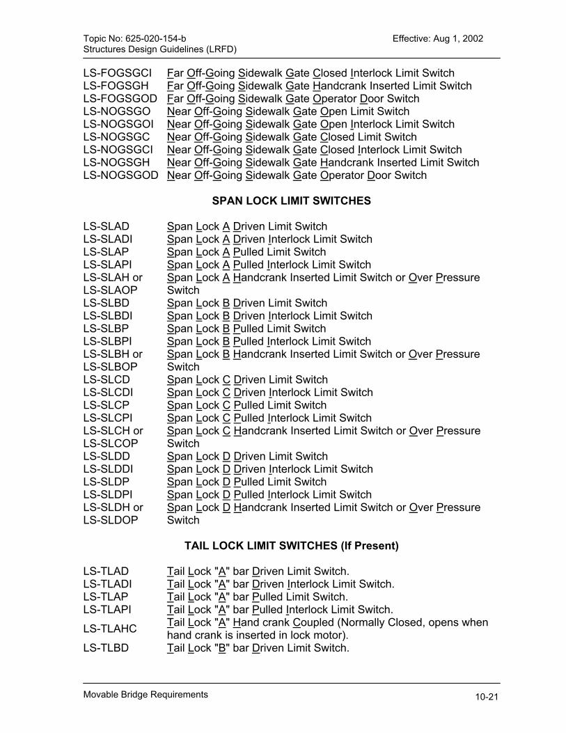
Topic No: 625-020-154-b Effective: Aug 1, 2002 Structures Design Guidelines (LRFD) LS-FOGSGCI Far Off-Going Sidewalk Gate Closed Interlock Limit Switch LS-FOGSGH Far Off-Going Sidewalk Gate Handcrank Inserted Limit Switch LS-FOGSGOD Far Off-Going Sidewalk Gate Operator Door Switch LS-NOGSGO Near Off-Going Sidewalk Gate Open Limit Switch LS-NOGSGOI Near Off-Going Sidewalk Gate Open Interlock Limit Switch LS-NOGSGC Near Off-Going Sidewalk Gate Closed Limit Switch LS-NOGSGCI Near Off-Going Sidewalk Gate Closed Interlock Limit Switch LS-NOGSGH Near Off-Going Sidewalk Gate Handcrank Inserted Limit Switch LS-NOGSGOD Near Off-Going Sidewalk Gate Operator Door Switch
SPAN LOCK LIMIT SWITCHES LS-SLAD Span Lock A Driven Limit Switch LS-SLADI Span Lock A Driven Interlock Limit Switch LS-SLAP Span Lock A Pulled Limit Switch LS-SLAPI Span Lock A Pulled Interlock Limit Switch LS-SLAH or LS-SLAOP
Span Lock A Handcrank Inserted Limit Switch or Over Pressure Switch
LS-SLBD Span Lock B Driven Limit Switch LS-SLBDI Span Lock B Driven Interlock Limit Switch LS-SLBP Span Lock B Pulled Limit Switch LS-SLBPI Span Lock B Pulled Interlock Limit Switch LS-SLBH or LS-SLBOP
Span Lock B Handcrank Inserted Limit Switch or Over Pressure Switch
LS-SLCD Span Lock C Driven Limit Switch LS-SLCDI Span Lock C Driven Interlock Limit Switch LS-SLCP Span Lock C Pulled Limit Switch LS-SLCPI Span Lock C Pulled Interlock Limit Switch LS-SLCH or LS-SLCOP
Span Lock C Handcrank Inserted Limit Switch or Over Pressure Switch
LS-SLDD Span Lock D Driven Limit Switch LS-SLDDI Span Lock D Driven Interlock Limit Switch LS-SLDP Span Lock D Pulled Limit Switch LS-SLDPI Span Lock D Pulled Interlock Limit Switch LS-SLDH or LS-SLDOP
Span Lock D Handcrank Inserted Limit Switch or Over Pressure Switch
TAIL LOCK LIMIT SWITCHES (If Present)
LS-TLAD Tail Lock "A" bar Driven Limit Switch. LS-TLADI Tail Lock "A" bar Driven Interlock Limit Switch. LS-TLAP Tail Lock "A" bar Pulled Limit Switch. LS-TLAPI Tail Lock "A" bar Pulled Interlock Limit Switch.
LS-TLAHC Tail Lock "A" Hand crank Coupled (Normally Closed, opens when hand crank is inserted in lock motor).
LS-TLBD Tail Lock "B" bar Driven Limit Switch.
Movable Bridge Requirements 10-21
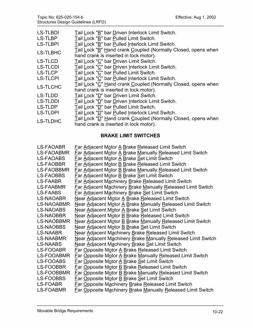
Topic No: 625-020-154-b Effective: Aug 1, 2002 Structures Design Guidelines (LRFD) LS-TLBDI Tail Lock "B" bar Driven Interlock Limit Switch. LS-TLBP Tail Lock "B" bar Pulled Limit Switch. LS-TLBPI Tail Lock "B" bar Pulled Interlock Limit Switch.
LS-TLBHC Tail Lock "B" Hand crank Coupled (Normally Closed, opens when hand crank is inserted in lock motor).
LS-TLCD Tail Lock "C" bar Driven Limit Switch. LS-TLCDI Tail Lock "C" bar Driven Interlock Limit Switch. LS-TLCP Tail Lock "C" bar Pulled Limit Switch. LS-TLCPI Tail Lock "C" bar Pulled Interlock Limit Switch.
LS-TLCHC Tail Lock "C" Hand crank Coupled (Normally Closed, opens when hand crank is inserted in lock motor).
LS-TLDD Tail Lock "D" bar Driven Limit Switch. LS-TLDDI Tail Lock "D" bar Driven Interlock Limit Switch. LS-TLDP Tail Lock "D" bar Pulled Limit Switch. LS-TLDPI Tail Lock "D" bar Pulled Interlock Limit Switch.
LS-TLDHC Tail Lock "D" Hand crank Coupled (Normally Closed, opens when hand crank is inserted in lock motor).
BRAKE LIMIT SWITCHES
LS-FAOABR Far Adjacent Motor A Brake Released Limit Switch LS-FAOABMR Far Adjacent Motor A Brake Manually Released Limit Switch LS-FAOABS Far Adjacent Motor A Brake Set Limit Switch LS-FAOBBR Far Adjacent Motor B Brake Released Limit Switch LS-FAOBBMR Far Adjacent Motor B Brake Manually Released Limit Switch LS-FAOBBS Far Adjacent Motor B Brake Set Limit Switch LS-FAABR Far Adjacent Machinery Brake Released Limit Switch LS-FAABMR Far Adjacent Machinery Brake Manually Released Limit Switch LS-FAABS Far Adjacent Machinery Brake Set Limit Switch LS-NAOABR Near Adjacent Motor A Brake Released Limit Switch LS-NAOABMR Near Adjacent Motor A Brake Manually Released Limit Switch LS-NAOABS Near Adjacent Motor A Brake Set Limit Switch LS-NAOBBR Near Adjacent Motor B Brake Released Limit Switch LS-NAOBBMR Near Adjacent Motor B Brake Manually Released Limit Switch LS-NAOBBS Near Adjacent Motor B Brake Set Limit Switch LS-NAABR Near Adjacent Machinery Brake Released Limit Switch LS-NAABMR Near Adjacent Machinery Brake Manually Released Limit Switch LS-NAABS Near Adjacent Machinery Brake Set Limit Switch LS-FOOABR Far Opposite Motor A Brake Released Limit Switch LS-FOOABMR Far Opposite Motor A Brake Manually Released Limit Switch LS-FOOABS Far Opposite Motor A Brake Set Limit Switch LS-FOOBBR Far Opposite Motor B Brake Released Limit Switch LS-FOOBBMR Far Opposite Motor B Brake Manually Released Limit Switch LS-FOOBBS Far Opposite Motor B Brake Set Limit Switch LS-FOABR Far Opposite Machinery Brake Released Limit Switch LS-FOABMR Far Opposite Machinery Brake Manually Released Limit Switch
Movable Bridge Requirements 10-22

Topic No: 625-020-154-b Effective: Aug 1, 2002 Structures Design Guidelines (LRFD) LS-FOABS Far Opposite Machinery Brake Set Limit Switch LS-NOOABR Near Opposite Motor A Brake Released Limit Switch LS-NOOABR Near Opposite Motor A Brake Manually Released Limit Switch LS-NOOABS Near Opposite Motor A Brake Set Limit Switch LS-NOOBBR Near Opposite Motor B Brake Released Limit Switch LS-NOOBBMR Near Opposite Motor B Brake Manually Released Limit Switch LS-NOOBBS Near Opposite Motor B Brake Set Limit Switch LS-NOABR Near Opposite Machinery Brake Released Limit Switch LS-NOABMR Near Opposite Machinery Brake Manually Released Limit Switch LS-NOABS Near Opposite Machinery Brake Set Limit Switch
AUXILIARY DRIVE LIMIT SWITCHES (If Present) LS-FOADC Far Opposite Auxiliary Drive Coupled (Normally Closed, opens
when drive is coupled). LS-FAADC Far Adjacent Auxiliary Drive Coupled (Normally Closed, opens
when drive is coupled). LS-NOADC Near Opposite Auxiliary Drive Coupled (Normally Closed, opens
when drive is coupled). LS-NAADC Near Adjacent Auxiliary Drive Coupled (Normally Closed, opens
when drive is coupled). Design each movable leaf with FULL-CLOSED, NEAR-CLOSED, NEAR-OPEN, FULL-OPEN, and FULL-SEATED limit switches. Specify NEMA 4, corrosion resistant metallic housings which have a high degree of electrical noise immunity and a wide operating range. Specify that NEAR-OPEN and NEAR-CLOSED limit switches be mounted, initially, approximately eight (8) degrees from FULL-OPEN and FULL-CLOSED, respectively. Final adjustment of NEAR-OPEN and NEAR-CLOSED will depend upon bridge configuration, drive machinery, and bridge operation. Commentary: The FULL-CLOSED switch controls the drive stop and the FULL-SEATED switch is the safety interlock to allow driving the locks. Do not connect limit switches in series. Connect each limit switch to a relay coil or a PLC input. Provide position encoder (potentiometer or other type) to drive leaf position indicators on control console. The position encoder will also provide a signal to the PLC to use as a reference to determine leaf limit switch failure. Connect limit switches in the following configurations: Traffic Gates: End-Of-Travel configuration. Span Locks: End-Of-Travel configuration. Leaf(s): End-Of-Travel configuration. Safety Interlocks: Indicating configuration. Do not use electronic limit switches. Plunger type switches are optional.
Movable Bridge Requirements 10-23

Topic No: 625-020-154-b Effective: Aug 1, 2002 Structures Design Guidelines (LRFD)
10.7.9 Safety Interlocking [AASHTO 8.4.1] A. Traffic Lights: Traffic gates LOWER is not enabled until traffic lights RED.
Provide bypass capability labeled TRAFFIC LIGHT BYPASS to allow traffic gates LOWER without traffic lights RED.
B. Traffic Gates: 1.) Bridge Opening: Span locks PULL is not enabled until all traffic gates are
fully down (or TRAFFIC GATE BYPASS has been engaged). 2.) Bridge Closing: Traffic lights GREEN is not enabled until all traffic gates are
fully raised (or TRAFFIC GATE BYPASS has been engaged). 3.) Provide bypass capability labeled TRAFFIC GATE BYPASS to allow span
lock PULL without all traffic gates LOWERED or traffic lights GREEN without all traffic gates RAISED.
C. Span Locks: 1.) Bridge Opening: Leaf RAISE is not enabled until all span locks are fully
pulled (or SPAN LOCK BYPASS has been engaged). 2.) Bridge Closing: Traffic gate RAISE is not enabled until all span locks are fully
driven (or SPAN LOCK BYPASS has been engaged). 3.) Provide bypass capability and label SPAN LOCK BYPASS to allow leaf
RAISE without all span locks pulled or traffic gate RAISE without all span locks DRIVEN.
D. Leaf(s): 1.) Span locks DRIVE is not enabled until leaf (s) is(are) FULLY SEATED (as
indicated by the FULLY SEATED switch). 2.) Provide bypass capability and label LEAF BYPASS to allow span lock DRIVE
without leaf (s) FULLY SEATED.
10.7.10 Instruments [AASHTO 8.4.5] Provide wattmeter for each drive (pump) motor and provide leaf position indication for each leaf.
10.7.11 Control Console [AASHTO 8.4.6] Provide a Control Console that contains the necessary switches and indicators to perform semi-automatic and manual operations as required by the standard FDOT “Basic Sequence Diagram.” All wiring entering or leaving the Control Console shall be broken across approved terminals. No components other than push buttons, selector switches, indicating lights, terminal blocks, etc., shall be allowed in the Control Console. Refer to the “Technical Special Provisions” issued by the Mechanical/Electrical Section of the SDO.
Movable Bridge Requirements 10-24

Topic No: 625-020-154-b Effective: Aug 1, 2002 Structures Design Guidelines (LRFD) 10.7.12 Electrical Connections between Fixed and Moving Parts [AASHTO
8.9.5] Use extra flexible wire or cable.
10.7.13 Electrical Connections across the Navigable Channel [AASHTO 8.9.7] Specify a submarine cable assembly consisting of the following three separate cables: A. Power Cable: Jacketed and armored with twelve (12) #4 AWG copper and
twelve (12) #10 AWG copper conductors. B. Signal and Control Cable: Jacketed and armored with fifty (50) #12 AWG copper
and five (5) pairs of twisted shielded #14 AWG copper conductors. C. Bonding Cable: A single #4/0 AWG copper conductor. Determine the total number of conductors required of each size and the number of runs of each type of cable that is required for the project. Use only multiples of the standard cables listed above. Allow for at least 25% spare conductors for each size. Specify quick-disconnect type terminals for terminating conductors. Specify terminals that isolate wires from a circuit by a removable bridge or other similar means. Specify NEMA 4X enclosures for all terminals. Design all above the water line, vertical runs of cable with supports at every five feet. Specify and detail a protective sleeve (schedule 120 PVC) around the cable from a point 5 feet below the mean low tide to a point 5 feet above mean high tide. Specify a watertight seal at both ends of the sleeve.
10.7.14 Service Lights [AASHTO 8.11] Provide minimum of 30-foot candles in all areas of the machinery platform.
10.7.15 Navigation Lights [AASHTO 1.4.4.6.2] Design a complete navigation light and aids system in accordance with all local and federal requirements and Standard Drawings Nos. 510 and No. 511. Comply with the latest edition of the Code of Federal Regulations (CFR) 33, Part 118, and Coast Guard Requirements.
10.7.16 Grounding and Lightning Protection [AASHTO 8.12 AND 8.13] Provide the following systems: A. Lightning Protection System: Design per the requirements of NFPA 780 Lightning
Protection Code. Protect the bridge with Class II materials. B. Surge Suppression System: Design Transient Voltage Surge Suppressor (TVSS)
system to protect all power, control, signaling, and communication circuits and all submarine conductors that enter or leave the control house. It is imperative to
Movable Bridge Requirements 10-25
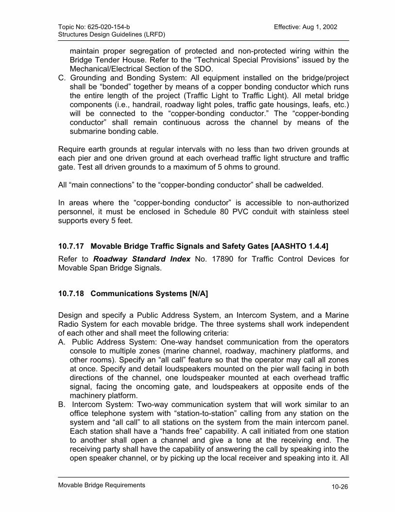
Topic No: 625-020-154-b Effective: Aug 1, 2002 Structures Design Guidelines (LRFD)
maintain proper segregation of protected and non-protected wiring within the Bridge Tender House. Refer to the “Technical Special Provisions” issued by the Mechanical/Electrical Section of the SDO.
C. Grounding and Bonding System: All equipment installed on the bridge/project shall be “bonded” together by means of a copper bonding conductor which runs the entire length of the project (Traffic Light to Traffic Light). All metal bridge components (i.e., handrail, roadway light poles, traffic gate housings, leafs, etc.) will be connected to the “copper-bonding conductor.” The “copper-bonding conductor” shall remain continuous across the channel by means of the submarine bonding cable.
Require earth grounds at regular intervals with no less than two driven grounds at each pier and one driven ground at each overhead traffic light structure and traffic gate. Test all driven grounds to a maximum of 5 ohms to ground. All “main connections” to the “copper-bonding conductor” shall be cadwelded. In areas where the “copper-bonding conductor” is accessible to non-authorized personnel, it must be enclosed in Schedule 80 PVC conduit with stainless steel supports every 5 feet.
10.7.17 Movable Bridge Traffic Signals and Safety Gates [AASHTO 1.4.4] Refer to Roadway Standard Index No. 17890 for Traffic Control Devices for Movable Span Bridge Signals.
10.7.18 Communications Systems [N/A] Design and specify a Public Address System, an Intercom System, and a Marine Radio System for each movable bridge. The three systems shall work independent of each other and shall meet the following criteria: A. Public Address System: One-way handset communication from the operators
console to multiple zones (marine channel, roadway, machinery platforms, and other rooms). Specify an “all call” feature so that the operator may call all zones at once. Specify and detail loudspeakers mounted on the pier wall facing in both directions of the channel, one loudspeaker mounted at each overhead traffic signal, facing the oncoming gate, and loudspeakers at opposite ends of the machinery platform.
B. Intercom System: Two-way communication system that will work similar to an office telephone system with “station-to-station” calling from any station on the system and “all call” to all stations on the system from the main intercom panel. Each station shall have a “hands free” capability. A call initiated from one station to another shall open a channel and give a tone at the receiving end. The receiving party shall have the capability of answering the call by speaking into the open speaker channel, or by picking up the local receiver and speaking into it. All
Movable Bridge Requirements 10-26

Topic No: 625-020-154-b Effective: Aug 1, 2002 Structures Design Guidelines (LRFD)
intercom equipment shall be capable of operation in a high noise, salt air environment. A handset shall be mounted adjacent to the control console, in each room on the bridge and on each machinery platform.
C. Marine Radio System: Hand held, portable, operable on or off the charger, tuned to the proper channels, and a 120-volt charger located adjacent to the operator's console.
10.7.19 Functional Checkout [N/A] Develop and specify an outline for performing system checkout of all mechanical/electrical components to insure contract compliance and proper operation. Specify in-depth testing to be performed by the Contractor. Functional testing for the electrical control system consists of two parts. Perform the first part before delivery, and the second part after installation on the bridge. Both tests shall be comprehensive. Perform the off-site functional testing to verify that all equipment is functioning as intended. All repairs or adjustments shall be made before installation on Department property. All major electrical controls shall be assembled and tested in one place, at one time. The test shall include as a minimum: control console, PLC, relay back-up system, Motor Control Center, and all other equipment required, in the opinion of the Electrical Engineer of Record, to complete the testing to the satisfaction of the Mechanical/Electrical Section of the SDO. If not satisfactory, repeat the testing at no cost to the Department. All equipment shall be assembled and inter-connected (as they would be on the bridge) to simulate bridge operation. No inputs or outputs shall be forced. Indication lights shall be provided to show operation and hand operated toggle switches may be used to simulate field limit switches. After the off-site testing is completed to the satisfaction of the Mechanical/Electrical Section of the SDO, the equipment may be delivered and installed. The entire bridge control system shall be re-tested before the bridge is put into service. The field functional testing shall include, but is not necessarily limited to, the off-site testing procedure. As a minimum, perform the following tests of Control Functions for both manual and semi-automatic operations: Commentary: The Electrical Engineer of Record is encouraged to include tests for other equipment not included in the minimum tests listed below. A. Demonstrate the correct operation of the bridge sequence as described in the
“Technical Special Provisions” and in the drawings.
Movable Bridge Requirements 10-27

Topic No: 625-020-154-b Effective: Aug 1, 2002 Structures Design Guidelines (LRFD) B. Demonstrate EMERGENCY STOP of each span (leaf) at, or during, each phase
of opening and closing the bridge (phases include ramping up or down, full-speed, and creep-speed).
C. Demonstrate EMERGENCY STOP does prevent energization of all rotating machinery in any mode of operation.
D. Demonstrate that the leaf (s) do not come to a sudden stop on a power failure. E. Interlocks:
1.) Simulate the operation of each limit switch to demonstrate correct operation and interlocking of systems.
2.) Demonstrate BYPASS operation for each failure for each required bypass. 3.) Simulate each failure for which there is an alarm message to demonstrate
correct message displays. 4.) Testing of interlocks shall be sufficient to demonstrate that unsafe or out of
sequence operations are prevented. 5.) Observe Position Indicator readings with bridge closed and full open to assure
correct readings. F. Navigation Lights:
1.) Demonstrate that all lamps are working. 2.) Demonstrate the operation of the transfer relays and indicators for each light. 3.) Demonstrate proper change of channel lights from red to green. 4.) Demonstrate Battery Backup by simulating a power outage.
G. Traffic Gates: 1.) Demonstrate proper operation of each gate arm. 2.) Demonstrate opening or closing times. Time should not exceed 15 seconds
in either direction. 3.) Demonstrate that gate arms are perpendicular to the roadway when RAISED
and parallel to the roadway when LOWERED. H. Span Locks:
1.) Operate each span lock through one complete cycle and record, with chart recorder, motor power (watts) throughout the operation, record lockbar to guide and lockbar to receiver, clearances.
2.) Demonstrate pulling and driving times. Time should not exceed 10 seconds in either direction.
3.) Operate each lock with hand crank or manual pump for one complete cycle. I. Emergency Power:
1.) The complete installation shall be initially started and checked-out for operational compliance by a factory-trained representative of the manufacturer of the generator set and the Automatic Transfer Switch. The supplier of the generator set shall provide the engine lubrication oil and antifreeze recommended by the manufacturer for operation under the environmental conditions specified.
2.) Upon completion of initial start-up and system checkout, the supplier of the generator set shall notify the Engineer in advance and perform a field test to demonstrate load-carrying capability, stability, voltage, and frequency.
Movable Bridge Requirements 10-28
Topic No: 625-020-154-b Effective: Aug 1, 2002 Structures Design Guidelines (LRFD)
3.) Specify a dielectric absorption test on generator winding with respect to ground. A polarization index shall be determined and recorded. Submit copies of test results to the Engineer.
4.) Phase rotation test shall be made to determine compatibility with load requirements.
5.) Engine shutdown features such as low oil pressure, over-temperature, over-speed, over-crank, and any other feature as applicable shall be function-tested.
6.) In the presence of the Engineer, perform resistive load bank tests at one hundred percent (100%) nameplate rating. Loading shall be 25%-rated for 30 minutes, 50%-rated for 30 minutes, 75%-rated for 30 minutes, and 100%-rated for 2 hours. Maintain records throughout this period and record water temperature, oil pressure, ambient air temperature, voltage, current, frequency, kilowatts, and power factor. The above data shall be recorded at 15-minute intervals throughout the test.
J. Automatic Transfer Switch: Perform automatic transfer by simulating loss of normal power and return to normal power. Monitor and verify correct operation and timing of: normal voltage sensing relays, engine start sequence, time delay upon transfer, alternate voltage sensing relays, automatic transfer operation, interlocks and limit switch function, timing delay and retransfer upon normal power restoration, and engine shut-down feature.
K. Programmable Logic Controller (PLC) Program: 1.) Demonstrate the completed program's capability prior to installation or
connection of the system to the bridge. Arrange and schedule the demonstration with the Engineer and the Electrical Engineer of Record.
2.) A detailed field test procedure shall be written and provided to the Electrical Engineer of Record for approval. Provide for testing as listed below: a.) Exercise all remote limit switches to simulate faults including locks, gates,
traffic lights, etc. Readouts shall appear on the alphanumeric display. b.) When the local testing of all individual remote components is completed,
check all individual manual override selections for proper operation at the console. When all override selections have been satisfactorily checked-out, switch the system into semi-automatic (PLC) mode and exercise for a full raise and lower cycle. Verify that operation is as diagrammed on the plan sheet for the sequence of events.
c.) Initiate a PLC sequence of operation interweaving the by-pass functions with the semi-automatic functions for all remote equipment.
d.) Remove the power from the input utility lines. The Automatic Transfer Switch (ATS) should activate the engine-generator to supply power. Raise and lower the bridge again. The bascule leafs should operate in sequence; i.e., two adjacent bascule leafs at a time. Upon completion of the test, re-apply utility power to ATS. The load should switch over to utility for normal operation.
e.) Certify that all safety features are included in the program, and that the program will not accept commands that are contrary to the basic
Movable Bridge Requirements 10-29

Topic No: 625-020-154-b Effective: Aug 1, 2002 Structures Design Guidelines (LRFD)
sequence diagram. Submit failure mode testing as part of the written field test procedure.
10.8 Control House Architectural Design
A control house is the ‘building’ designed as part of a moveable bridge (Bascule, ‘drawbridge’, etc.) which is occupied by the bridge operator. This facility houses the business functions, and mechanical & electrical systems used to operate the bridge. This includes equipment such as pumps, motors, generators, etc. and systems such as controls, lighting, plumbing, and HVAC. The design of new control houses and renovation of existing control houses shall comply with the requirements of the FLORIDA BUILDING CODE. A. Operation area(s) contain business functions. B. Equipment area(s) contain mechanical and electrical equipment.
10.8.1 General A. These guidelines are intended primarily for use in the design of new control
houses but many items apply to renovations of existing houses. B. The operator should be able to hear all traffic (vehicular and marine) as well as
see traffic from the primary work station(s) in the operation area(s). C. Heat gain can be a problem. Where sight considerations permit, insulated walls
should be used as a buffer against heat gain. Provide 4 to 5 foot roof overhangs. D. The preferred wall construction is reinforced concrete; minimum six inches thick
with architectural treatments such as fluted corner pilasters, arches, frieze ornamentation, horizontal banding or other relief to blend with local design considerations.
E. Finish exterior of house with stucco, Class V coating or spray-on granite or cast stone.
F. Design the Bridge Tenders Room with a minimum of 200 square feet of usable floor space. This allows enough room for a toilet, kitchenette, and coat/mop closet as well as wall-hung desk and control console. Add additional square footage for stairwells, or place stairs on exterior of structure.
G. Windowsills should be no more than 34 inches from the floor. This allows for operator vision when seated in a standard task chair.
H. Consideration should be given to lines of sight form control station during column sizing and spacing.
I. For operator standing at control console, verify site lines to: 1.) Traffic gates for both directions of automobile traffic. 2.) Marine traffic for both directions of the navigable channel. 3.) Locations where pedestrians normally will stop. 4.) Under side of bridge, at channel, via video cameras (4) with recording
capabilities for accident investigation.
Movable Bridge Requirements 10-30
Topic No: 625-020-154-b Effective: Aug 1, 2002 Structures Design Guidelines (LRFD) 10.8.2 Site Water Lines Specify pipe and fittings for site water lines including domestic water line, valves, fire hydrants and domestic water hydrants. Size to provide adequate pressure and detail drawings as necessary to show location and extent of work. Specify disinfection of potable water distribution system and all water lines per the requirements of American Water Works Association (AWWA).
10.8.3 Site Sanitary Sewage System Gravity lines to manholes are preferred. Avoid the use of lift stations. However if lift stations are required, special consideration must be given to daily flows as well as pump cycle times. Low daily flows result in long cycle times and associated odor problems. Include pump and flow calculations and assumptions in 60% submittal. For bridges which are not served by a local utility company, or where connection is prohibitively expensive, and where septic tanks are not permitted or practical, coast guard approved marine sanitation devices are acceptable.
10.8.4 Stairs, Steps and Ladders Stair treads shall be at least 3 feet wide and comply with codes in regard to riser and tread dimensions. Comply with OSHA requirements. The preferred tread is skid-resistant open grating. Avoid the use of ladders or stair ladders. Commentary: Ships ladders may be used, only as last resort for very limited height (4 feet vertical maximum). Stairs and landings may be on the exterior of the house. Commentary: This reduces heating and cooling requirements as well as providing more usable floor space. For interior stairwells, spiral stairs are acceptable although not preferred Minimum 6 foot diameter. Special attention must be paid to clearances for moving equipment into or out of a control house. Design stair assembly to support live load of 100 lbs/sq ft with deflection of stringer not to exceed 1/180 of span. Include calculations in 60% submittal. In situations where stairs cannot be accommodated, stair ladders may be used. Vertical ladders should not be used.
Movable Bridge Requirements 10-31

Topic No: 625-020-154-b Effective: Aug 1, 2002 Structures Design Guidelines (LRFD) 10.8.5 Handrails and Railing Specify standard I.P.S. size schedule 40 1½ inch O.D. steel or aluminum pipe with corrosion resistant, slip-on structural fittings that permit easy field installation and removal. Welded tube rails are not preferred. Design railing assembly, wall rails, and attachments to resist a load of 200 pounds at any point and in any direction, plus a continuous load of 50 psf in any direction without damage or permanent set. Include calculations in 60% submittal. Grating and Floor Plates. Specify skid resistant open grating, except at control level.
10.8.6 Framing and Sheathing A. Include a specification section for the following items if used:
1.) Structural floor, wall, and roof framing. 2.) Built-up structural beams and columns. 3.) Diaphragm trusses fabricated on site. 4.) Floor, wall, and roof sheathing. 5.) Sill gaskets and flashing. 6.) Preservative treatment of wood. 7.) Fire retardant treatment of wood. 8.) Telephone and electrical panel back boards. Concealed wood blocking for
support of toilet and bath accessories, wall cabinets, and wood trim. 9.) All other sections applicable to tender house design and construction.
10.8.7 Desktop and Cabinet A. Specify and detail a wall-hung desktop with drawer. Show desktop. B. Specify and detail a minimum 7 feet of 36-inch base cabinets and 7 feet of 24 or
36-inch wall cabinets. C. Specify cabinet hardware and solid-surfacing material counter-tops and desktop.
10.8.8 Insulation A. Design the tender house so that insulation meets the following requirements:
Walls - RI9, Roof assembly - R30. B. Board Insulation may be used at underside of floor slabs, exterior walls, and
between floors separating conditioned and unconditioned spaces. C. Batt Insulation may be used in ceiling construction and for filling perimeter and
door shim spaces, crevices in exterior wall and roof.
10.8.9 Fire-Stopping A. Specify, design, and detail fire-stopping for wall and floor penetrations.
1.) Main Floor Walls: 1 Hour 2.) Stair Walls (Interior): 2 Hours 3.) Interior Partitions: ¾ Hour
10.8.10 Roof A. Do not use flat roofs, “built-up” roofs, etc. B. Design: Hip roof with minimum 6:12 pitch and 4 to 5 foot overhang.
Movable Bridge Requirements 10-32

Topic No: 625-020-154-b Effective: Aug 1, 2002 Structures Design Guidelines (LRFD) C. Roof Material: Specify and detail either standing seam 18 gauge metal or glazed
clay tiles. Note: many of the coastal environments will void the manufacturer’s warranty for metal. Before specifying a metal roof determine if the manufacturer will warrant the roof in the proposed environment, if not, use tiles meeting or exceeding the Grade I requirements of ASTM C 1167.
D. Soffit: Specify ventilated aluminum or vinyl. E. Fascia: Specify aluminum, vinyl or stucco. F. Design for hurricane force uplift on roof, roof framing, decking, anchors and
other components. Include roof load and uplift calculations in 60% submittal. G. During design, consider underlayment, eave, and ridge protection, nailers and
associated metal flashing.
10.8.11 Doors And Hardware A. Specify and detail armored aluminum entry doors; ballistics rated for.357
Magnum fired at point blank range. B. Interior Doors:
1.) Passage - Solid core or solid wood 2.) Closets – Louvered
C. Hardware: 1.) Specify corrosion resistant, heavy-duty, commercial ball-bearing hinges and
levered locksets and dead bolts for entry doors. 2.) Specify adjustable thresholds, weather-stripping, seals and door gaskets. 3.) Specify interior locksets. 4.) Call for all locks keyed alike and spare keys.
10.8.12 Windows A. Specify windows complying with the American Architectural Manufacturers
Association standards (AAMA) for heavy commercial windows. B. Specify double-hung, marine glazed heavy commercial (DHHC) type extruded
aluminum windows. Glazing shall be ballistics-rated for .357 Magnum fired at point blank range.
C. Specify windows to be counter balanced to provide 60% lift assistance. D. Specify operating hardware and insect screens. E. Specify perimeter sealant. F. When ballistic glazing is required, specify glazing that is rated for .357 Magnum
round fired at point blank range. G. Structural Loads: ASTM E330-70. With 60-lb/sq ft [2.87 kPa] exterior uniform
load and 60-lb/sq ft [2.87 kPa] interior load applied for I0 seconds with no glass breakage, permanent damage to fasteners, hardware parts, actuating mechanisms or any other damage.
H. Air Leakage: No more than 0.35 cfm/min/sq ft [0.002cu m/s/sq in] of wall area, measured at a reference differential pressure across assembly of 1.57 psf [75 Pa] as measured in accordance with ASTM E283.
I. Water Leakage: None, when measured in accordance with ASTM E331 with a test pressure of 6 psf applied at 5 gallons per hour per square ft.
Movable Bridge Requirements 10-33

Topic No: 625-020-154-b Effective: Aug 1, 2002 Structures Design Guidelines (LRFD) 10.8.13 Veneer Plaster (Interior Walls) Specify ¼ inch plaster veneer over ½ inch moisture-resistant gypsum wallboard (blueboard), masonry and concrete surfaces.
10.8.14 Gypsum Board (Interior Walls) Specify ½ inch blueboard for plaster veneer. Specify ½ inch fiberglass reinforced cement backer board for tile. Specify taped and sanded joint treatment and smooth texture finish.
10.8.15 Floor Tile Specify non-skid quarry tile on tender's level. Do not use vinyl floor tiles or sheet goods.
10.8.16 Epoxy Flooring Specify fluid applied non-slip epoxy flooring for electrical rooms, machinery rooms and machinery platforms. Ensure that the manufacturer of the product warrants the product used and that it is installed per their instructions. Do not specify painted floors.
10.8.17 Painting Specify paint for woodwork and walls.
10.8.18 Wall Louvers Use rainproof intake and exhaust louvers and size to provide required free area. Design with minimum 40% free area to permit passage of air at a velocity of 335 ft/min [160 L/sec] without blade vibration or noise with maximum static pressure loss of 0.25 inches [6 mm] measured at 375 ft/m in [175 L/sec].
10.8.19 Toilet and Bath Accessories Specify a mirror, soap dispenser, tissue holder, paper towel dispenser, and a waste paper basket for each bathroom. Specify a bathroom exhaust fan. Porcelain water closet and lavatory.
10.8.20 Equipment and Appliances Specify a shelf mounted or built-in 1.5 cubic foot microwave with digital keypad and users manual. Specify an under counter refrigerator with users manual. Specify a fire extinguisher for each room. Type ABC 10.
10.8.21 Furnishings Specify two gas lift front-tilt task chairs. Provide one R5 cork bulletin board.
Movable Bridge Requirements 10-34

Topic No: 625-020-154-b Effective: Aug 1, 2002 Structures Design Guidelines (LRFD) Specify window treatment (blinds or shades).
10.8.22 Pipe and Fittings Specify pipe fittings, valves, and corporation stops, etc. Provide hose bib outside house. Provide wall-mounted, corrosion resistant (fiberglass or plastic) hose hanger and 50-foot nylon reinforced ¾ inch garden hose in a secure area. Provide stops at all plumbing fixtures. Provide primed floor drains. Provide air traps to eliminate/reduce water hammer. Provide ice maker supply line.
10.8.23 Plumbing Fixtures Specify a single bowl, stainless steel, self-rimming kitchen counter sink, a sink faucet, a lavatory, a lavatory faucet, and an elongated toilet. Do not specify ultra-low flow fixtures unless the bridge has a marine digester system. Specify all trim, stops, drains, tail pieces, etc. for each fixture. Provide 10-gallon water heater for kitchen sink and lavatory.
10.8.24 Heating, Ventilating and Air Conditioning A central split unit is preferred but multiple, packaged units may be acceptable for rehabs. Design HVAC system with indoor air handler, duct work and out-door unit(s). Perform load calculations and design the system accordingly. Include load calculations in 60% or 75% submittal. For highly corrosive environments use corrosive resistant equipment. Specify packaged terminal air conditioning units. Specify packaged terminal heat pump units. Specify and detail wall sleeves and louvers. Specify controls. Specify and show ceiling fans on floor plan. Specify ventilation equipment for machinery levels and attic.
10.8.25 Interior Luminaires Specify fixtures under section 508 of FDOT Standard Specifications for Road and Bridge Construction, current adopted edition. Avoid the use of heat producing fixtures. Do not use PCV Ballasted lighting fixtures.
10.8.26 Video Equipment Cameras (4): One camera each channel direction to provide full view of channel and fender system and one camera each direction of traffic to provide view of all travel lanes and sidewalks. Monitors (4): One for each camera. Provide recording capabilities for each camera.
Movable Bridge Requirements 10-35
Topic No: 625-020-154-b Effective: Aug 1, 2002 Structures Design Guidelines (LRFD) 10.9 Maintainability
10.9.1 General The following guidelines for maintainability of movable bridges are applicable to both new bridges and to rehabilitation plans for existing bridges on which construction has not been initiated. Variations from these practices for the rehabilitation of existing bridges may be authorized by the Mechanical/Electrical Section of the SDO, but only by approval in writing.
10.9.2 Trunnion Bearings Design trunnion bearings so that replacement of bushings can be accomplished with the span jacked ½ inch [12 mm] and in a horizontal position. Provide suitable jacking holes or puller grooves in bushings to permit extraction. Jacking holes shall utilize standard bolts pushing against the housing that supports the bushing. Specify trunnion bushings and housings of a split configuration. The bearing cap and upper-half bushing (if an upper-half bushing is required) shall be removable without span jacking or removal of other components.
10.9.3 Span-Jacking of New Bridges Stationary stabilizing connector points are located on the bascule pier. These points provide a stationary support for stabilizing the span, by connection to the span stabilizing connector points. Locate one set of span-jacking surfaces under the trunnions (normally, this will be on the bottom surface of the bascule girder). Locate a second set on the lower surface at the rear end of the counterweight. Locate span stabilizing connector points on the bascule girder forward and back of the span jacking surfaces. The stationary stabilizing connector point (forward) shall be in the region of the Live Load Shoe. Locate stationary stabilizing connector points (rear) on the cross girder support at the rear of the bascule pier. Provide connector points to attach stabilizing structural steel components. Commentary: Position the stationary jacking surface at an elevation as high as practical so that standard hydraulic jacks can be installed. The following definitions of terms used above describe elements of the span-jacking system: Span-jacking Surface: An area located under the trunnion on the bottom surface of the bascule girder. Span Stabilizing Connector Point (forward): An area adjacent to the live load shoe point of impact on the bottom surface of the bascule girder. Span Stabilizing Connector Point (rear): An area at the rear end of the counterweight on the lower surface of the counterweight girder. (NOTE: For bascule bridges having
Movable Bridge Requirements 10-36
Topic No: 625-020-154-b Effective: Aug 1, 2002 Structures Design Guidelines (LRFD) tail locks, the span stabilizing connector point may be located on the bottom surface of the lockbar receiver located in the counterweight.) Stationary Jacking Surface: The surface located on the bascule pier under the span jacking surfaces. The stationary jacking surface provides an area against which to jack in lifting the span.
10.9.4 Trunnion Alignment Features Provide center holes in trunnions to allow measurement and inspection of trunnion alignment. Span structural components shall not interfere with complete visibility through the trunnion center holes. Provide individual adjustment for alignment of trunnions. Provide a permanent walkway or ladder with work platform to permit inspection of trunnion alignment.
10.9.5 Lock Systems Span locks are to be accessible from the bridge sidewalk through a suitable hatch or access door. Provide a work platform suitable for servicing of the lockbars under the deck and in the region around the span locks. Design lock systems to allow disabling an individual lock, for maintenance or replacement, without interfering with the operation of any of the other lockbars on the bascule leaf. Design tail locks, when required, so that the lockbar mechanism is accessible for repair without raising the leaf. The lockbar drive mechanism shall be accessible from a permanently installed platform within the bridge structure. Provide adjustable lockbar clearances for wear compensation.
10.9.6 Machinery Drive Systems Design machinery drive assemblies so that components are individually removable from the drive system without removal of other major components of the drive system. Commentary: For example, a speed-reducer assembly can be removed by breaking flexible couplings at the power input and output ends of the speed-reducer.
10.9.7 Lubrication Provisions Bridge system components requiring lubrication shall be accessible without use of temporary ladders or platforms. Provide permanent walkways and stairwells to permit free access to regions requiring lubrication. Lubrication fittings shall be visible, clearly marked and easily reached by maintenance personnel.
Movable Bridge Requirements 10-37

Topic No: 625-020-154-b Effective: Aug 1, 2002 Structures Design Guidelines (LRFD) Designs for automatic lubrication systems shall provide for storage of not less than three (3) months supply of lubricant without refilling. Refill shall be accomplished within a period of 15 minutes through a vandal-proof connection box located on the bridge sidewalk, clear of the roadway. Blockage of one traffic lane during this period is permitted.
10.9.8 Drive System Bushings All bearing housings and bushings in open machinery drive and lock systems shall utilize split-bearing housings and bushings and shall be individually removable and replaceable without affecting adjacent assemblies.
10.9.9 Local Switching Provide "Hand-Off-Automatic" switching capability for maintenance operations on traffic gate controllers and brakes and motors for center and tail-lock systems. Provide "On-Off" switching capability for maintenance operations on span motor and machinery brakes, motor controller panels, and span motors. Remote switches shall be lockable for security against vandalism.
10.9.10 Service Accessibility Provide a service area not less than 30 inches wide around system drive components.
10.9.11 Service Lighting and Receptacles Provide lighting of machinery and electrical rooms as necessary to assure adequate lighting for maintenance of equipment, but with a minimum lighting level of 30 fc [300 Lux]. Provide switching so that personnel may obtain adequate lighting without leaving the work area for switching. Provide master switching from the control tower. Provide each work area with receptacles for supplementary lighting and power tools such as drills, soldering and welding equipment.
10.9.12 Communications Provide permanent communications equipment between the control tower and areas requiring routine maintenance (machinery drive areas, power and control panels locations traffic gates and waterway).
10.9.13 Wiring Diagrams Provide wiring diagrams for each electrical panel inside the panel door. Enclose diagrams in glass or plastic of optical quality.
Movable Bridge Requirements 10-38

Topic No: 625-020-154-b Effective: Aug 1, 2002 Structures Design Guidelines (LRFD) 10.9.14 Diagnostic Reference Guide for Maintenance Specify diagnostic instrumentation and system fault displays for mechanical and electrical systems. Malfunction information shall be presented on a control system monitor located in the bridge control house. Data shall be automatically recorded. System descriptive information, such as ladder diagrams and wiring data, shall be available on the system memory to enable corrective actions on system malfunctions and to identify areas requiring preventative maintenance.
10.9.15 Navigation Lights Specify dual lamps and transfer relays with two long-life, 130 volt, brass base, 100W lamps; or LED array of at least 12 particularly bright RED or GREEN LEDs symmetrically arranged around the lens focal point and with a minimum of 50,000 hour life on fenders and center of channel positions to reduce effort required for maintenance of navigation lights.
10.9.16 Working Conditions for Improved Maintainability When specified by the Department, for either new or rehabilitated bascule bridge design, use enclosed machinery and electrical equipment areas. Air-condition areas containing electronic equipment to protect the equipment as required by the equipment manufacturer and the Mechanical/Electrical Section of the SDO.
10.9.17 Weatherproofing New and rehabilitated bascule bridge designs shall incorporate details to prevent water drainage and sand deposition into machinery areas. Avoid details that trap dirt and water; provide drain holes, partial enclosures, sloped floors, etc., to minimize trapping of water and soil.
Movable Bridge Requirements 10-39

Topic No: 625-020-154-b Effective: Aug 1, 2002 Structures Design Guidelines (LRFD)
Figure 10-1 Speed Ramp
Movable Bridge Requirements 10-40
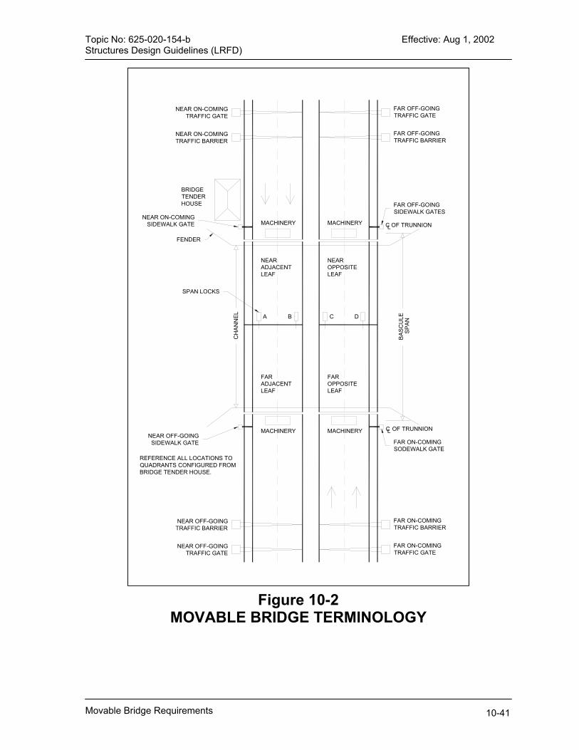
Topic No: 625-020-154-b Effective: Aug 1, 2002 Structures Design Guidelines (LRFD)
A B C D
MACHINERY MACHINERY
MACHINERY MACHINERY
NEARADJACENTLEAF
NEAROPPOSITELEAF
CH
ANN
EL
BASC
ULE
OF TRUNNIONLC
SPAN
FAR OFF-GOING TRAFFIC GATE
NEAR ON-COMING TRAFFIC GATE
NEAR OFF-GOING TRAFFIC BARRIER
FAR ON-COMING TRAFFIC BARRIER
NEAR ON-COMING TRAFFIC BARRIER
FAR OFF-GOING TRAFFIC BARRIER
NEAR OFF-GOING TRAFFIC GATE
FAR ON-COMING TRAFFIC GATE
REFERENCE ALL LOCATIONS TO QUADRANTS CONFIGURED FROM BRIDGE TENDER HOUSE.
BRIDGE TENDER HOUSE
C OF TRUNNIONL
FARADJACENTLEAF
FAROPPOSITELEAF
FAR OFF-GOING SIDEWALK GATES
NEAR ON-COMING SIDEWALK GATE
FENDER
SPAN LOCKS
FAR ON-COMING SODEWALK GATE
NEAR OFF-GOING SIDEWALK GATE
Figure 10-2 MOVABLE BRIDGE TERMINOLOGY
Movable Bridge Requirements 10-41

Topic No: 625-020-154-b Effective: Aug 1, 2002 Structures Design Guidelines (LRFD)
MIN2.6 'D'
'D'BORE
MINIMUM 2"BACKING RING
MINIMUM 2"HUB FLANGE
NOT LESS THAN20% OF BORE
NOT LESS THAN'D' HUB DEPTH
NOT LESS THAN2 BOLT DIAMETERS
MINIMUM 2"WEB
120°
TRUNNION HUB DESIGN GUIDE
MINIMUM 1" BOLTS
2 PINDIAMETERS
Dowell Pins
Figure 10-3 Trunnion Hubs
Movable Bridge Requirements 10-42

Topic No: 625-020-154-b Effective: Aug 1, 2002 Structures Design Guidelines (LRFD)
Figure 10-4 Lock Design Criteria
Movable Bridge Requirements 10-43

Topic No: 625-020-154-b Effective: Aug 1, 2002 Structures Design Guidelines (LRFD)
Figure 10-4 Lock Design Criteria
Movable Bridge Requirements 10-44

Topic No: 625-020-154-b Effective: Aug 1, 2002 Structures Design Guidelines (LRFD)
Chapter 11 BRIDGE COST ESTIMATING
11.1 General A Structures Design Bulletin will be issued in the first quarter of 2003 publishing unit costs associated with this procedure and reflect recent bid data. The purpose of the procedure established in this chapter is to bring uniformity to the cost estimating portion of the decision making process. The purpose of the Bridge Development Report is to select the most appropriate structure type for the site under consideration. One of the most important considerations is to select the most cost efficient bridge to fit the unique circumstances at the site. For information purposes, selected project cost data is provided in the appendix. The cost estimating procedure supplied herein should be used for all bridge structures with the exception of the structure types stated below. This process is not suitable for cost estimating structure types without repeatable bid history including the following bridge types: movable; cable stayed; cast-in-place on form travelers; arches and tunnels. These very unique structures should be cost estimated by the use of fundamental process of developing cost based on labor, materials, equipment and construction time. This concept for cost estimating is a three-step process. The first step is to utilize the average unit material costs provided herein to develop a cost estimate based on the completed preliminary design. The second step is to adjust the total bridge cost for the unique site conditions by use of the site adjustment factors. The third and final step is to review the computed total bridge cost on a cost per square foot basis and compare this cost against the historical cost range for similar structure types. This three-step process should produce a reasonably accurate cost estimate for structure type selection. It should be noted that an ambitious work program and market conditions could significantly affect the costs shown here. Verify current costs before completing estimate. If the estimated cost is outside the cost range in step three, provide documented reasons for the variance in cost.
11.2 Cost Estimating Process The applicability of this three-step process is explained in the general section. The process stated below is developed for estimating the bridge cost after the completion of the preliminary design that includes member selection, member size and member reinforcing. This process will develop costs for the bridge superstructure and substructure from beginning to end bridge. Costs for all other items including but not limited to the following are excluded from the costs provided in this chapter:
Bridge Cost Estimating 11-1

Topic No: 625-020-154-b Effective: Aug 1, 2002 Structures Design Guidelines (LRFD)
Bridge Cost Estimating 11-2
mobilization, operation costs for existing bridge(s); removal of existing bridge or bridge fenders; lighting; walls; embankment; fenders; approach slabs; maintenance of traffic; load tests; bank stabilization.