design guidelines for erosion and sediment control for highways
TRANSCRIPT

APPENDIX C
March 25, 2003
APPENDIX C
EROSION AND SEDIMENTATION CONTROL BEST MANAGEMENT PRACTICES (BMP)

APPENDIX C
March 25, 2003
This page left blank intentionally.

APPENDIX C
March 25, 2003 C-1
LIST OF TABLES Table C-1 Erosion Control Measures – Protection of Exposed Surface Table C-2 Erosion Control Measures – Control of Runoff Table C-3 Sediment Control Measures Table C-4 Minimum Measures for Erosion Sediment Control LIST OF BMP's BMP # BMP Description 1. Silt Fence 2a-c. Gabions 3. Brush or Rock Filter Berm 4. Continuous (earth-filled geotextile) Berm 5. Earth Dyke Barrier 6a-f. Storm Drain Inlet Sediment Barrier 7. Rock Check Dam 8. Aggregate Filled Sand Bag Check Dam 9. Log Check Dam 10. Synthetic Permeable (Ditch) Barrier 11. Straw Bale Check Dam 12. Straw Bale Barrier 13a. Rolled Erosion Control Products (RECP) Channel Installation 13b. Rolled Erosion Control Products (RECP) Slope Installation 14a-b. Riprap Armouring 15. Cellular Confinement System 16. Gravel Blankets 17a. Energy Dissipator for Culvert Outlet 17b. Energy Dissipator for Trough Drains at Bridge Headslope 18a. Sediment Basin and Trap (riser outlet option) 18b. Sediment Basin (Type I) and Trap (Type II) (permeable rock berm outlet option) 19a-b. Slope Drains 20. Groundwater Control (Subsurface Drain) 21. Offtake Ditch 22. Seeding 23. Mulching 24. Hydroseeding-Hydromulching 25. Topsoiling 26. Sodding 27a-b. Planting Trees and Shrubs (a) Live Staking, (b) Brush Layering 28a-b. Fibre Rolls and Waffles 29. Chemical Stabilization (Tackifiers) 30. Riparian Zone Preservation 31. Pumped Silt Control Systems 32. Scheduling 33. Stabilized Worksite Entrances 34a-c. Slope Texturing

APPENDIX C
March 25, 2003 C-2
DRAWING LISTING BMP #1 Silt Fence BMP #2a Gabions (Slope and Bank) BMP #2b Gabions (Single Gabion) Drop Structure for Ditch Channel BMP #2c Gabions (Double Gabion) "Energy Dissipator" Drop Structure for Ditch Channel BMP #3 Brush or Rock Filter Berms BMP #4 Continuous (earth-filled geotextile) Berm BMP #5 Earth Dike Barrier BMP #6a Storm Drain Drop Inlet Sediment Barrier (Block and Gravel - Option 1) BMP #6b Storm Drain Curb Inlet Sediment Barrier (Block and Gravel – Option 2) BMP #6c Storm Drain Curb Inlet Sediment Barrier (Sandbags – Option 1) BMP #6d Storm Drain Curb and Gutter Sediment Barrier BMP #6e Storm Drain Drop Inlet Sediment Barrier (Straw Bale/Gravel Option) BMP #6f Storm Drain Drop Inlet Sediment Barrier (Silt Fence – Option) BMP #7 Rock Check Dam BMP #9 Log Check Dam BMP #10 Synthetic Permeable (ditch) Barriers BMP #11 Straw Bale Check Dam BMP #12 Straw Bale Barrier BMP #13a Rolled Erosion Control Product (RECP) Channel Installation BMP #13b Rolled Erosion Control Product (RECP) Slope Installation BMP #14a Riprap Armouring for Slope BMP #14b Riprap Armouring for Channel BMP #15 Cellular Confinement System for Slope Stabilization BMP #17a Energy Dissipator for Culvert Outlet BMP #17b Energy Dissipator for Semi-Circular Trough Drain Terminal Protection for Bridge
Headslope BMP #18a Typical Sediment Basin (Riser Outlet Option) BMP #18b Typical Sediment Basin (Permeable Rock Berm Outlet Option) BMP #19a Slope Drain BMP #19b Overside Drain BMP #21 Offtake Ditch BMP #27a Live Staking BMP #27b Brush Layering BMP #28a Straw Rolls BMP #28b Wattle (Live Fascine) BMP #31 Pumped Silt Control System BMP #33 Temporary Gravel Construction Entrance/Exit BMP #34a Surface Roughening BMP #34b Grooved or Serrated Slope BMP #34c Stepped or Terraced Slope

25 Topsoiling X X X X
22 Seeding X X X X
23 Mulching X X X X
24 Hydroseeding - Hydromulching X X X X
26 Sodding X X X X
14 Riprap Armoring X X
16 Gravel Blankets X X
13Rolled Erosion
Control Products (RECP)
X X
15Cellular
Confinement System
X X
BMP # BMP NameAdvantages Limitations
Comments
Not readily used in Alberta highway construction, expensive, installation is labour intensive (hand installation), not suitable for slopes steeper than 1H:1V
Cannot be effective without seeding and allowing time for plant growth; not appropriate for slopes steeper than 2H:1V (steep slopes will require soil covering over topsoil and specialized design); dry topsoil susceptible to wind erosion, susceptible to erosion prior to establishment of vegetation
Lightweight cellular system and easily installed, uses locally available soils or grout for fill to reduce costs,
Placing topsoil provides excellent medium for vegetation root structure to develop in; organic content promotes plant growth, reuse organics (topsoil or peat) stripped from the site at start of grading; absorb raindrop energy to minimize erosion potential
Application of mulch on steep slopes may be difficult, may require additional specialized equipment not commonly used in typical highway construction
Site must be accessible to hydroseeding-hydromulching equipment (usually mounted on trucks with a maximum hose range of approximately 150 m), may require subsequent application in areas of low growth as part of maintenance program
Expensive, labour intensive to install (hand installation), sod may not be readily available in all areas of the province, relatively short 'shelf-life' (sod can't be stored on-site for excessive periods of time)
Expensive, may require heavy equipment to transport rock to site and place rock, may not be feasible in areas of the province where appropriate rock is not readily available, may be labour intensive to install (hand installation); generally thickness of riprap is higher when compared to gabion mattress
Must be designed by qualified geotechnical personnel, expensive, may not be feasible in areas of the province where gravel is not readily available, areas of high groundwater seepage may require placement of non-woven geotextile underlay and additional drainage measures
RECP use must be based on design need and risk assessment of site, certification on QA/QC of RECP products must be issued by the AT approved supplier on pre-approved products, certification of physical properties and performance criteria (tractive resistance) is required (permissible velocities can be provided as reference), labour intensive to install, temporary blankets may require removal prior to restarting construction activities, RECP not suitable for rocky slopes, proper site preparation is required to seat RECP onto soil correctly; high performance is tied to successful vegetation growth
Economical and effective on large areas, mulch tackifier may be used to provide immediate protection until seed germination and vegetation is established, allows re-vegetation of steep slopes where conventional seeding/mulching techniques are very difficult, relatively efficient operation, also provides dust and wind erosion control
Used alone to protect exposed areas for short periods, protects soil from rainsplash erosion, preserves soil moisture and protects germinating seed from temperature extremes, relatively inexpensive measure of promoting plant growth and slope protection
Stabilizes soil surface with rock lining thus minimizing erosion, permits construction traffic in adverse weather, may be used as part of permanent base construction of paved areas, easily constructed and implemented, can be used to stabilize seepage piping erosion of slope
Provides a protective covering to bare soil or topsoiled surface where degree of erosion protection is high, can be more uniform and longer lasting than mulch, wide range of commercially available products
Table C-1: Erosion Control Measures - Protection of Exposed Surface
Provides immediate vegetation and protection, instant buffer strip and/or soft channel lining, can be used on steep slopes, relatively easy to install, may be repaired if damaged, aesthetically pleasing
Most applicable as channel lining with geotextile underlay, used for soils where vegetation not easily established, effective for high velocities or concentrations, permits infiltration, dissipates energy of flow from culvert inlets/outlets, easy to install and repair, very durable and virtually maintenance free, flexible lining for ditches with ice build-up
Applications
Must be applied over prepared surface (topsoiled), grasses may require periodic maintenance (mowing), uncut dry grass may be a fire hazard, seeding for steep slopes may be difficult, seasonal limitations on seeding effectiveness may not coincide with construction schedule, freshly seeded areas are susceptible to runoff erosion until vegetation is established, reseeding may be required for areas of low growth
Inexpensive and relatively effective erosion control measure, effectiveness increases with time as vegetation develops, aesthetically pleasing, enhances terrestrial and aquatic habitat
SlopesDitches and
ChannelsLarge Flat
Surface AreasBorrow And
Stockpile Area
Page 1

BMP # BMP NameAdvantages Limitations
Comments
Table C-1: Erosion Control Measures - Protection of Exposed Surface
Applications
SlopesDitches and
ChannelsLarge Flat
Surface AreasBorrow And
Stockpile Area
27 Planting Trees and Shrubs X X X
29 Chemical Stabilization X X X
30 Riparian Zone Preservation X X X X
32 Scheduling X X X X
34 Slope Texturing X X
Identifies protection issues and plans for efficient, orderly construction of BMPs; minimizes bare soil exposure and erosion hazard; allows early installation of perimeter control for sediment entrapment; and early installation of runoff control measures; good construction practice
Roughens slope surface to reduce erosion potential and sediment yield; suitable for clayey soils
Additional cost; not suitable for silty and sandy soils; not practical for slope length <8 m for dozer operation up/down slope
Preserve a native vegetation buffer to filter and slow runoff before entering sensitive (high risk) areas, most effective natural sediment control measure, slows runoff velocity, filters sediment from runoff, reduces volume of runoff on slopes
Stipulate construction activities with careful planning to include preservation areas, freshly planted vegetation for newly created riparian zones requires substantial periods of time before they are as effective as established vegetation at controlling sediment
Expensive, may be labour intensive to install, not readily used in Alberta highway construction projects, revegetated areas are subject to erosion until plants are established, plants may be damaged by wildlife, watering is usually required until plants are established
Establishes vegetative cover and root mat, reduces flow velocities on vegetative surface, traps sediment laden runoff, aesthetically pleasing once established, grows stronger with time as root structure develops, usually has deeper root structure than grass
Not commonly used in highway construction projects, may be expensive, site must be accessible to spraying equipment, may require specialized equipment, temporary measure only, higher application rates may prevent seed germination and growth, crust-forming chemical stabilizers may crack during freeze-thaw cycles, requires specialized design
Increase cohesion of soil thus reduces soil moisture evaporation and erosion, easily applied, may be applied in conjunction with hydroseeding-hydromulching, longevity increases as application rate increases
Page 2

34 Slope Texturing X X X
21 Offtake Ditch X X X
17 Energy Dissipator X X
19 Slope (Down) Drains X
2 Gabions X
7 Rock Check Dam X X
8
Aggregate Filled Sand Bag Check
Dam
X X
9 Log Check Dam X
11 Straw Bale Check Dam X X
10Synthetic
Permeable Barriers
X
BMP Name Limitations
Pipes must be sized appropriately to accommodate anticipated flows, erosion can occur at inlet/outlet if protection is not incorporated into design, slope drain must be anchored to slope
Construction may be labour intensive (hand installation), extra costs associated with gabion basket materials
Channel must be sized appropriately to accommodate anticipated flow volumes and velocities, lining may be required, may require design by qualified personnel, must be graded to maintain positive drainage to outlets to minimize ponding
Small diameter rocks/stones can be dislodged; grouted rip-rap armouring may breakup due to hydrostatic pressures, frost heaves, or settlement; may be expensive, may be labour intensive to install; may require design by qualified personnel for extreme flow volumes and velocities
BMP #AdvantagesSlopes
Comments
Ditches and Channels
Large Flat Surface Areas
Borrow And Stockpile Area
May increase grading costs, may cause sloughing in sensitive (wet) soils, tracking may compact soil, provides limited sediment and erosion control and should not be used as primary control measure
Temporary measure only; not appropriate for: channels draining areas larger than 2 ha (5 acres), channels steeper than 5%, and/or flow velocities greater than 0.3 m/s; requires extensive maintenance after high flow storm events, must be installed by hand with keying and staking; maximum height of one straw bale
More effective as energy dissipator to slow flow velocities, cheaper than gabions or armouring entire ditch, easily constructed and reusable
Rip rap or sandbags slow runoff velocity and dissipate flow energy to non-erosive level in relatively short distances, permits sediment collection from runoff
Collects and diverts sheet flow or runoff water at the top of a slope to reduce downslope erosion potential, incorporated with permanent project drainage systems
Relatively maintenance free, permanent drop structure, long lasting (robust), less expensive and thickness than rip-rap, allows smaller diameter rock/stones to be used, relatively flexible, commercially available products, commonly used in Alberta highway construction projects; suitable for resisting high flow velocity
Directs surface water runoff into drain pipe instead of flowing over and eroding exposed soils of slope face
Permanent drop structure with some filtering capability, cheaper than gabion and armouring entire channel, easily constructed, commonly used in Alberta highway construction projects
Contouring and roughening (tracking) of slope face reduces runoff velocity and increases infiltration rates; collects sediment; holds water, seed and mulch better than smooth surfaces; promotes development of vegetation, provides loss of soil reduction in soil erosion compared with untracked slopes
Table C-2: Erosion Control Measures - Control of Runoff
Applications
Not to be used as check structures, must be installed by hand in conjunction with RECP, become brittle in winter and are easily damaged by construction equipment or recreational vehicles, only partially effective in retaining some sediment, primarily used for reducing flow velocities and energy dissipation
Reusable/moveable, reduces flow velocities and dissipate flow energy; retains some sediments; used as grade breaks in conjunction with sturdy permanent drop structures along steep grades
Temporary drop structures appropriate for channel slopes with 3% to 5% grades, straw bales are readily available in most areas of the province, biodegradable
Equally effective as silt fences for sediment trapping and straw bale barriers as drop structure, may include timber salvaged from site during clearing operations, most applicable at clearing/grubbing stages of construction
Can be expensive in areas of limited rock source, not appropriate for channels draining areas larger than 10 ha (4 acres), requires extensive maintenance after high flow storm events, susceptible to failure if water undermines or outflanks structure
Not appropriate for channels draining areas larger than 2 ha (5 acres), requires extensive maintenance after high flow storm events, low filtering capabilities, labour intensive to install (hand installation), temporary measure only
May be expensive, not commonly used after stripping stage, not appropriate for channels draining areas larger than 4 ha (10 acres), labour intensive to construct, gaps between logs may allow sediment laden runoff to escape, logs/timbers will rot over time (not permanent)
Page 1

BMP Name Limitations
BMP #AdvantagesSlopes
Comments
Ditches and Channels
Large Flat Surface Areas
Borrow And Stockpile Area
Table C-2: Erosion Control Measures - Control of Runoff
Applications
20
Groundwater Control
(Subsurface Drain)
X
28 Fibre Rolls and Wattles X
32 Scheduling X X X X
Requires design by a geotechnical engineer; can be a slope instability issue
Labour intensive to install (hand installation), designed for slope surfaces with low flow velocities, designed for short slope lengths with a maximum slope of 2H:1V, not widely used on Alberta highway construction projects
Identifies protection issues and plans for efficient, orderly construction of BMPs; minimizes bare soil exposure and erosion hazard; early installation of perimeter control for sediment entrapment; and early installation of runoff control measures; good construction practice
Relief subsurface groundwater seepage and winter ice build-up; lower groundwater table to minimize piping erosion; enhance slope stability performance
Function well in freeze-thaw conditions, low cost solution to sheet flow and rill erosion on slopes, low to medium cost flow retarder and silt trap, can be used on slopes too steep for silt fences or straw bale barriers, biodegradable
Page 2

SlopesDitches
and Channels
Large Flat Surface Areas
Borrow And
Stockpile Advantages Limitations
30 Riparian Zone Preservation X X X X
Preserve a native vegetation buffer to filter and slow runoff before entering sensitive (high risk) areas, most effective natural sediment control measure, slows runoff velocity, filters sediment from runoff, reduces volume of runoff on slopes
Stipulate construction activities with careful planning to include preservation areas, freshly planted vegetation for newly created riparian zones requires substantial periods of time before they are as effective as established vegetation at controlling sediment
12 Straw Bale Barrier X X Relatively inexpensive if bales are locally available, biodegradable, cheaper and easier to install than other barriers
Short service life due to biodegradation, straw bales may not be readily available in all areas of the province, maximum barrier height of one straw bale, require extensive maintenance after high flow storm events, require proper keying and staking
3 Brush or Rock Filter Berm X X X X
More effective than silt fences, uses timber and materials salvaged from site during clearing and grubbing, can be wrapped and anchored with geotextile fabric envelope
More expensive than silt fences, temporary measure only, not effective for diverting runoff, expensive to remove, not to be used in channels or ditches with high flows
28 Fibre Rolls and Wattles X
Function well in freeze-thaw conditions, low cost solution to sheet flow and rill erosion on slopes, low to medium cost flow retarder and silt trap, can be used on slopes too steep for silt fences or straw bale barriers, biodegradable
Labour intensive to install (hand installation), designed for slope surfaces with low flow velocities, designed for short slope lengths with a maximum slope of 2H:1V, not widely used on Alberta highway construction projects
31Pumped Silt
Control Systems (Silt Bags)
X
Filter bag is lightweight and portable, simple set up and disposal, sediment-laden water is pumped into and contained within filter bag for disposal, different aperture opening sizes (AOS) available from several manufacturers; for emergency use only under overflow conditions
May be expensive, requires special design needs for use, not readily used in Alberta highway construction projects, requires a pump and power source for pump, suitable for only short periods of time and small volumes of sediment laden water, can only remove particles larger than aperture opening size (AOS)
1 Silt Fence X X XEconomical, most commonly used sediment control measure, filters sediment from runoff and allows water to pond and settle out coarse grained sediment, more effective than straw bale barriers
May fail under high runoff events, applicable for sheet flow erosion only, limited to locations where adequate space is available to pond collected runoff, sediment build up needs to be removed on a regular basis, damage to filter fence may occur during sediment removal, usable life of approximately one year
5 Earth Dyke/Barrier X X Easy to construct, relatively inexpensive as local soil and material is used; can be easily converted to Sediment Pond/Basin (BMP #18)
Geotechnical design required for fill heights in excess of 3 m, may not be suitable for all soil types or sites; riprap spillway and/or permeable outlet may be required
2 Gabions X
Relatively maintenance free, permanent drop structure, long lasting (robust), less expensive and thickness than rip-rap, allows smaller diameter rock/stones to be used, relatively flexible, commercially available products, commonly used in Alberta highway construction projects; suitable for resisting high flow velocity
Construction may be labour intensive (hand installation), extra costs associated with gabion basket materials
7 Rock Check Dam X XPermanent drop structure with some filtering capability, cheaper than gabion and armouring entire channel, easily constructed, commonly used in Alberta highway construction projects
Can be expensive in areas of limited rock source, not appropriate for channels draining areas larger than 10 ha (4 acres), requires extensive maintenance after high flow storm events, susceptible to failure if water undermines or outflanks structure
8Aggregate Filled Sand Bag Check
DamX X More effective as energy dissipator to slow flow velocities, cheaper than
gabions or armouring entire ditch, easily constructed and reusable
Not appropriate for channels draining areas larger than 2 ha (5 acres), requires extensive maintenance after high flow storm events, low filtering capabilities, labour intensive to install (hand installation), temporary measure only
BMP #
Filte
ring
and
Ent
rapm
ent
Table C-3: Sediment Control Measures
BMP Name
Applications Comments
Page 1

SlopesDitches
and Channels
Large Flat Surface Areas
Borrow And
Stockpile Advantages Limitations
BMP #
Table C-3: Sediment Control Measures
BMP Name
Applications Comments
9 Log Check Dam XEqually effective as silt fences for sediment trapping and straw bale barriers as drop structure, may include timber salvaged from site during clearing operations, most applicable at clearing/grubbing stages of construction
Not commonly used after stripping stage, not appropriate for channels draining areas larger than 4 ha (10 acres), labour intensive to construct, gaps between logs may allow sediment laden runoff to escape, logs/timbers will rot over time (not permanent)
11 Straw Bale Check Structures X X
Temporary drop structures appropriate for channel slopes with 3% to 5% grades, straw bales are readily available in most areas of the province, biodegradable
Temporary measure only; not appropriate for: channels draining areas larger than 2 ha (5 acres), channels steeper than 5%, and/or flow velocities greater than 0.3 m/s; requires extensive maintenance after high flow storm events, must be installed by hand with keying and staking; maximum height of one straw bale
10Synthetic
Permeable Barriers
XReusable/moveable, reduces flow velocities and dissipate flow energy; retains some sediments; used as grade breaks in conjunction with sturdy permanent drop structures along steep grades
Partially effective as check dam structure, must be installed by hand in conjunction with RECP, become brittle in winter and are easily damaged by construction equipment or recreational vehicles, only partially effective in retaining some sediment, primarily used for reducing flow velocities and energy dissipation
4Continuous (earth-
filled geotextile) Berm
X X X Temporary measure; divert and intercept sheet or overlaid flow to form pond and allow sedimentation; ;flexibility of shape of construction; no trenching
Require specialized continuous berm machine to manufacture earth-filled geotextile berm on site; sandy/gravel soil is preferable fill material
6 Storm Drain Inlet - /Sediment Barrier X Temporary measure; easy to install and remove Limited sediment entrapment capacity; requires regular clean-out
maintenance
32
All
BM
Ps
Scheduling X X X X
Identifies protection issues and plans for efficient, orderly construction of BMPs; minimizes bare soil exposurte as erosion hazard; early installation of perimeter control for sediment entrapment; early dimension planning of runoff control measures; good construction practice
18
Impo
undm
ent
Sediment Pond/Basin X X
May be constructed of a variety of materials, collects sediment laden runoff and reduces velocity of flow and deposition of sediment, can be cleaned and expanded as needed, capable of handling large volumes of sediment laden runoff
Normally requires 250 m3/ha storage volume per area of exposed soil, Can require large areas of land, requires periodic maintenance to remove sediment build up, requires design by qualified personnel, usually requires 'back-up' control measures in case pond/basin overflows,
Filte
ring
and
Ent
rapm
ent
Page 2

SlopeDitches
and Channels
Large Flat Surface Areas
Borrow And
Stockpile Area
Advantages Limitations
Minimize Exposed Soils X X X X
Minimizes disturbed soil area, decreases erosion potential and decreases quantity of sediment and sediment control measures required thus decreasing costs May require efficient scheduling of topsoiling/seeding completed areas, limits the stripping of new areas
Operate During Fisheries Windows X X X X Minimizes possible negative impacts on aquatic wildlife May affect schedule of adjoining works
Maximize Favourable Weather X X X X
Increasing work capacity in favourable conditions, minimizes volume of work required in less desirable (wet) conditions, thus decreasing potential for erosion and sediment loss May require additional equipment and resources to increase scale of production/construction
Install BMP's Early X X X XEarly installation of sediment and erosion control measures ensures sediment losses are minimized during construction and provide good housekeeping May cause difficulties with site access or traffic
Avoid Wet Weather Periods X X X X Avoiding construction in wet weather periods minimizes erosion potential Shutdowns may prolong/delay construction activities
Topsoil and Seed Early X X X Topsoiling and seeding as early as possible covers exposed soil and reduces erosion potential
Surface Roughen (Slope Texturing) X X Texturing of soils along contours reduces erosion potential by as much as 10% Equipment may need to be retasked at a slight increase in costs
Preserve and Use Existing Drainage Systems
X X X X Minimize disturbance of drainage pattern Care must be taken to observe drainage directions
Control Construction Traffic X
Controlling where traffic is allowed avoids over-trafficking sensitive areas or areas with increased disturbance Forcing traffic into localized areas may increase disturbance in high-traffic areas
Signage X X X XClearly labeling sensitive zones or areas not to be disturbed ensures all workers on-site are aware of where work can occur and where it cannot thus minimizing confusion Increased costs of signs
Table C-4: Minimum Measures (Planning Strategies) for Erosion and Sediment Control
Measures
CommentsApplications

Silt Fence (Filter Fence) Sediment Control
B.M.P. #1
March 18, 2003 BMP #1-1
Description and Purpose • Permeable fabric barriers installed vertically on support posts along contours to collect and/or
filter sediment laden sheet flow runoff • Causes water to pond allowing sediment to settle out as water filters through fabric • Decreases flow velocity in channels with low to moderate flows (< 0.03 m3/s) • Entraps and minimizes coarse sediment from sheet flow or overland flow from entering
waterbodies • Perimeter control for sediment transport and deposition Applications • Temporary measure • Used at bottom of cut or fill slopes to collect sediment laden runoff • Used in swales or ditches with low flow velocity and flow less than 0.03 m3/s • Used along streams (or channels) banks • Used around stockpiles • Midslope grade-break (using "J-hook" or "smile" pattern to effect ponding, filtering and
sedimentation) Advantages • Low permeability silt fences have high filtering capabilities for fine sand to coarse silt • Filter fence more effective than straw bales at filtering out sediment Limitations • Applicable for sheet flow, normally cannot handle concentrated channel flow volumes • May fail under high runoff events • Limit to locations suitable for temporary ponding of sediment laden runoff • Not to be used in swales or ditches with flow greater than 0.03 m3/s • Low permeability silt fences may not be strong enough to support weight of water retained
behind it and may require reinforcement (i.e. wire mesh and stronger support post) • Sediment build up needs to be removed at 1/2 height and on a regular basis • Damage to fence may occur during sediment removal • Useable life of approximately one year dependent on maintenance and sediment requirement

Silt Fence (Filter Fence) Sediment Control
B.M.P. #1
May 27, 2003 BMP #1-2
Construction (Waiver: For guidance only. A site specific design is required from designer/engineer) • Two methods of installation are commonly used
– Trench method – Mechanical (slicing) installation method (e.g. Tommy Silt Fence Machine or equivalent)
• Trench Method – Select location of silt fence (usually along contours) – Drive support posts a minimum of 0.3 (preferable 0.6 m) into ground, spaced a maximum
of 2 m apart – Excavate trench approximately 0.15 m deep by 0.15 m wide for entire length of fence
along upstream side of posts – Attach the wire mesh or snow fencing, if used as reinforcement to fence fabric, to
upstream side of posts with staples – Extend filter fabric to base of trench and attach over wire mesh or snow fence, if used, on
upstream side of posts – Backfill and compact soil in trench, being careful not to damage fence
• Mechanical Installation Method – Select location of silt fence (usually along contours) – Use mechanical installation machine to embed the fabric a minimum of 0.15 m into the
ground. One mechanical installation method is by slicing (with special equipment) the geotextile fabric to embed into the ground without excavation and backfill. Minor disturbance of ground if affected and only tamping of ground is required for compaction.
– Drive support posts a minimum of 0.3 (preferable 0.6 m) into ground, spaced a maximum of 2 m apart
– Attach the wire mesh or snow fencing, if used as reinforcement to silt fence fabric, to upstream side of posts with staples
– Extend filter fabric to base of trench and attach over wire mesh or snow fence, if used, on upstream side of posts
Construction Considerations • Site Selection
– Size of drainage area should be no greater than 0.1 ha per 30 m length of silt fence – Maximum flow path length above silt fence should be no greater than 30 m – Maximum slope gradient above the silt fence should be no greater than 2H:1V – For use in swales, gradient should be less than 2% and drainage area less than 0.8 ha
• Fence should be placed on contour to produce proper ponding • Fence should be placed far enough away from toe of slope to provide adequate ponding area
(minimum of 1.8 m away from toe of slope is recommended) • Ends of fence should be angled upslope to collect runoff • Fence should not extend more than 0.6 m above grade • Posts can be wood or metal material dependent on design and ground conditions

Silt Fence (Filter Fence) Sediment Control
B.M.P. #1
May 27, 2003 BMP #1-3
• Posts should be placed on downstream side of fence • Posts should be driven at least 0.3 m (preferable 0.6 m) into the ground • Posts should not be spaced greater than 2 m apart • Wire mesh or standard snow fencing may be placed between the posts and filter fabric to
provide additional strength and support reinforcement • Filter fabric should be cut from a continuous roll to avoid joints (if joints are necessary, the
wrapping of fabric around the fence post and a minimum overlap of 0.2 m with staples should be used to attach the fabric to the post)
• Fence (and wire mesh or snow fence, if used) should be attached to posts with heavy duty staples, tie wires, or hog rings
• Fence (and wire mesh or snow fence, if used) should be dug into a trench at least 0.15 m deep to prevent undercutting of fence by runoff
• Trench backfill should be compacted • Long runs of silt fence are more prone to failure than short runs
– Maximum length of each section of silt fence should be 40 m – Silt fence should be installed in 'J' hook or 'smile' configuration, with maximum length of
40 m, along contours allowing an escape path for ponded water (minimizes overtopping of silt fence structure)
Inspection and Maintenance • Inspections should occur twice per week and after significant storm events (1:2 year storm
event and/or +40 mm rainfall over 24 hours duration) • Repair undercut fences and repair or replace split, torn, slumping or weathered fabric
immediately • Sediment build up should be removed once it accumulates to a depth of 0.2 m or at ½ height
of fence • Remove fence after vegetation is established • Deactivate fabric by cutting-off top portion of fabric above ground; bottom trenched-in
portion of fence fabric can be left in-ground thus minimizing ground disturbance Similar Measures • Straw Bales • Rock Barrier • Check Dams • Permeable/Synthetic Barriers

Silt Fence (Filter Fence) Sediment Control
B.M.P. #1
March 18, 2003 BMP #1-4
Design Considerations • For a silt fence system to work as a whole, the following factors should be considered:
1) quantity – adequate number and frequency of fence for efficient ponding and sedimentation
2) installation – workmanship 3) compaction – backfill and trenching of fabric 4) support – posts adequately embedded and of strong material and close spacings 5) attachment – secure fabric to post
• Install silt fences in a 'J' hook or 'smile' configuration to allow efficient ponding and sedimentation as well as escape route for excess runoff along the ends – Minimizes overtopping of structure

Typical SectionB.M.P. #1
Page 1 of 3

Typical SectionB.M.P. #1
Page 2 of 3

Typical SectionB.M.P. #1
Page 3 of 3

Silt Fence (Filter Fence) Sediment Control
B.M.P. #1
March 18, 2003 BMP #1-8
This page left blank intentionally.

Gabions (a – c) Erosion Control and Sediment Control
B.M.P. #2 (a-c)
March 18, 2003 BMP #2-1
Description and Purpose • Consist of rock placed inside wire baskets to protect steep or erodible slopes from sheet flow
erosion • Protects erodible stream channel banks from potentially high erosive concentrated flow
velocities or high tractive forces a) Slope and Banks b) Single Gabion Drop Structure for Ditch Channel c) Double Gabion "Energy Dissipator" Drop Structure for Ditch Channel Applications • Permanent measure • May be used on stream bank aprons and blankets where flow velocities do not exceed 6 m/s • May be constructed to 0.5H:1V as a low height toe protection structure of slope • May be used on slopes up to 1.5H:1V as slope protection, a grade break and sediment barrier
– Gabion matting is an alternative to riprap armouring of channels • May be used to construct dikes or weirs • Used as a drop structure (check structure) to reduce grade between structures and as sediment
barrier in channels • Used as a splash pad to slow down flow velocity and dissipate flow energy Advantages • Relatively maintenance free • Long lasting and sturdy structure • Lower thickness requirement for gabion (can be 1/2 to 1/3 riprap thickness) compared with
riprap thickness for identical severe hydraulic conditions. • Allows smaller diameter rock material to be used where it would normally be erodible with
riprap placement • Gabions are porous, free-draining and flexible so they are less affected by frost heaving and
hydrostatic pressures • Trap sediment and support plant growth to effect higher channel resistance to flow; however,
cumulative built-up of silt may render gabion less effective with a diminished height Limitations • Construction is labour intensive • Extra costs associated with wire for mesh cages and rock fill plus geotextile fabric or sand
filter layer

Gabions (a – c) Erosion Control and Sediment Control
B.M.P. #2 (a-c)
March 18, 2003 BMP #2-2
Construction (Waiver: For guidance only. A site specific design is required from designer/engineer) • Prepare subgrade at designated gabion location to found on mineral soil • Subexcavate trench a minimum of 0.15 m deep to 'key- in' gabion structure • Construct gabion basket as per manufacturers recommendations • Line interior of basket with non-woven geotextile OR a gravely sand filter layer (if required
by design) along areas where the basket is in contact with soil – Geotextile must be non-woven fabric to act as a separator (filter) between rock- infill and
subgrade soils to minimize infiltration of fine grained particles into the gabion structure • Backfill basket with rock with wire bracing at 1/3 points (or 0.3 m spacings) • Install gabion basket top • Backfill trench and compact soil around edges of comple ted basket Construction Considerations • Gabions should be placed on a properly graded surface • Non-woven geotextile should be used to prevent loss of underlying material and infiltration
of fine grained particles into the gabion structure • Rock in the baskets may be placed by hand to enhance dense packing of stones and decrease
void spaces • Construct gabions with internal wire diaphragms to maintain structural stability (shape) Inspection and Maintenance • Should be inspected after major storm events, especially where undermining at the toe of the
basket is a concern – Repairs as necessary; repair may include hand grading and/or infilling undermined area
with rocky material • Removal and clean out requirement of silt should be determined based on amount of
siltation, the level channel erosion and vegetation re-establishment observed Similar Measures • Berms/Barriers • Check Dams • Permeable/Synthetic Barriers • Rock/Brush barriers • Sand/Gravel Bag Barriers

Gabions (a – c) Erosion Control and Sediment Control
B.M.P. #2 (a-c)
March 18, 2003 BMP #2-3
Design Considerations • The design should include an energy dissipator (i.e. a gabion mat as a splash pad) at toe of
downstream side of gabion if overtopping of the gabion is anticipated.

Typical SectionB.M.P. #2a

Typical SectionB.M.P. #2b

Typical SectionB.M.P. #2c

Brush or Rock Filter Berm Sediment Control
B.M.P. #3
March 18, 2003 BMP #3-1
Description and Purpose • Temporary barriers of brush wrapped in filter fabric and secured in place, or rock anchored in
place to intercept and filter sediment laden stormwater runoff from disturbed areas, retain sediment, and release water as sheet flow
Applications • Temporary measure • Perimeter control • Near toe of slopes subjected to sheet flow and rill erosion • Along crest or tops streams and channels • Around drain inlets • Maximum drainage area of less than 250 m2 per 25 m length of barrier Advantages • May be equally effective filter as silt fences Limitations • Temporary measure only • Maximum drainage area of less than 250 m2 per 25 m length of barrier • Sufficient area behind berm required for ponding and clean out of sediment • Not effective for diverting runoff (filters allow runoff to seep through) • Rock filter berms are expensive to remove at completion of service life • Not to be used across ditches, channels, or swales where high concentrated flows are
anticipated Construction (Waiver: For guidance only. A site specific design is required from designer/engineer) • Brush filter berm
– Size of the brush filter berm will vary depending upon amount of material available and condition of the site
– The height of the berm shall be at least 1 m tall and the width shall be a minimum of 1.5 m at its base
– Berm is constructed by piling brush, roots, stumps and/or stones into a mounded row along contours – During clearing and grubbing, equipment can push the material into windrows along
toe of slopes or other areas prone to erosion

Brush or Rock Filter Berm Sediment Control
B.M.P. #3
March 18, 2003 BMP #3-2
– Filter fabric is then laid across the berm, with edges overlapping, and secured in a trench immediately upstream of the berm – Trench shall be 15 cm wide and 15 cm deep and shall run for the entire length of the
berm – The filter fabric in the trench shall be staked down with stakes spaced approximately 1 m
apart – The trench is then backfilled and compacted over the staked filter fabric – The fabric is anchored with twine/wire to stakes on the downstream side of the berm
• Rock filter berm – Constructed similar to brush filter berm, replacing brush with rock (D50 = 75 mm to
150 mm) Construction Considerations • Use rock or brush material smaller than 150 mm in diameter, or use filter cloth to encapsulate
the material, to promote filtration • There is no predetermined shape for filters • Water must be forced to filter through the berm and not flow around it • Brush barriers can generally be constructed of clean organic material made available from
clearing and grubbing operations that is normally burned or discarded • Rock and brush filter berms are temporary measures and should be removed upon
completion of service life, but not prior to revegetation of areas upslope Inspection and Maintenance • Inspect berms on a weekly basis and before and after significant rainfall events (1:2 year
storm event and/or 40 mm rainfall over 24 hours duration) • Reshape berms as needed and replace lost or dislodged rock, brush, and/or filter fabric • Inspect for sediment accumulation and remove sediment when depths reach approximately
one-third the berm height or 300 mm, whichever occurs first • Inspect for toe undercutting, weathered/deteriorated filter fabric, and end runs and erosion of
the filter and repair immediately Similar Measures • Berms/Barriers • Check Dams • Permeable/Synthetic Barriers • Sand/Gravel Bag Barriers

Brush or Rock Filter Berm Sediment Control
B.M.P. #3
March 18, 2003 BMP #3-3
• Design Considerations • Material properties
– Rocks – Shall consist of hard, durable, clean mineral particles free of organic matter, clay
lumps, soft particles, or other substances that might interfere with drainage and filtering properties
– D50 of 75 mm to 150 mm preferable
• Brush – Material shall be less than 150 mm in diameter

Typical SectionB.M.P. #3
Continuous (Earth-Filled Geotextile) Berm Sediment Control
B.M.P. #4
March 18, 2003 BMP #4-1
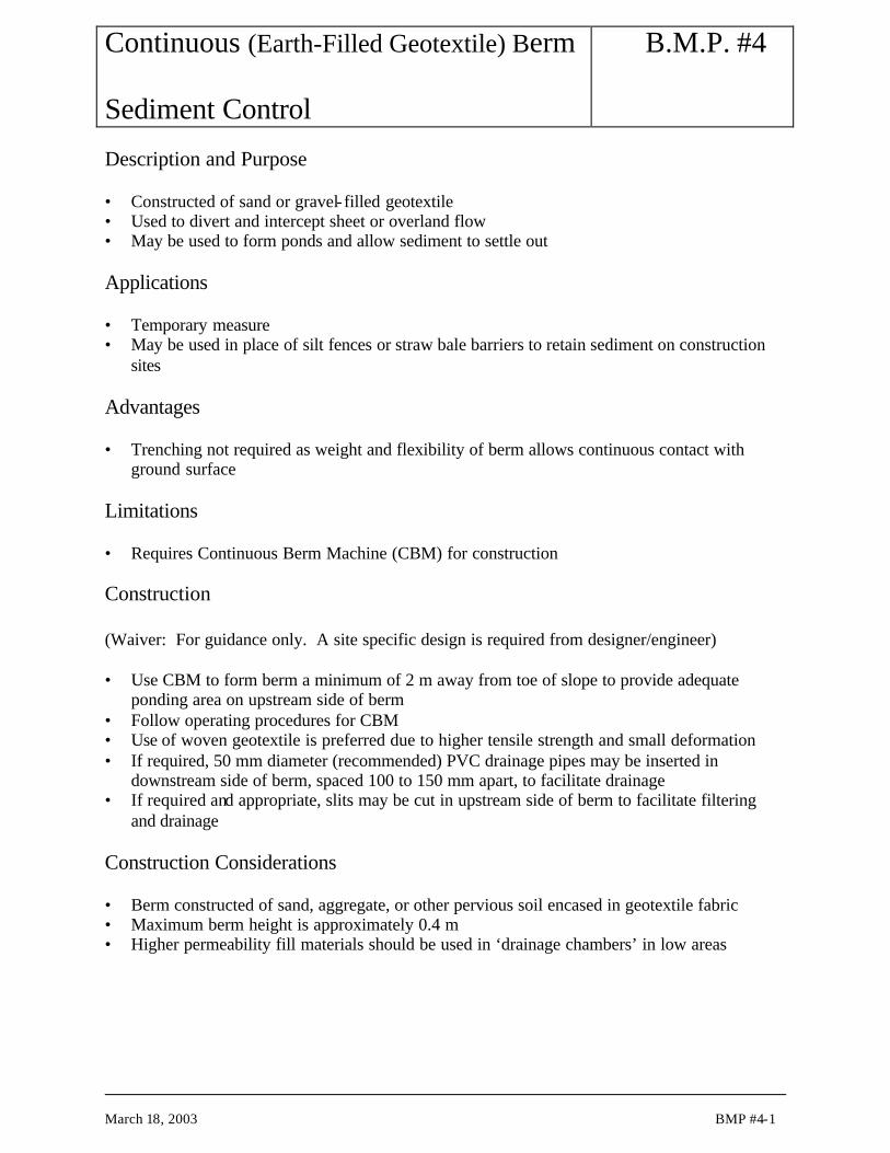
Description and Purpose • Constructed of sand or gravel- filled geotextile • Used to divert and intercept sheet or overland flow • May be used to form ponds and allow sediment to settle out Applications • Temporary measure • May be used in place of silt fences or straw bale barriers to retain sediment on construction
sites Advantages • Trenching not required as weight and flexibility of berm allows continuous contact with
ground surface Limitations • Requires Continuous Berm Machine (CBM) for construction Construction (Waiver: For guidance only. A site specific design is required from designer/engineer) • Use CBM to form berm a minimum of 2 m away from toe of slope to provide adequate
ponding area on upstream side of berm • Follow operating procedures for CBM • Use of woven geotextile is preferred due to higher tensile strength and small deformation • If required, 50 mm diameter (recommended) PVC drainage pipes may be inserted in
downstream side of berm, spaced 100 to 150 mm apart, to facilitate drainage • If required and appropriate, slits may be cut in upstream side of berm to facilitate filtering
and drainage Construction Considerations • Berm constructed of sand, aggregate, or other pervious soil encased in geotextile fabric • Maximum berm height is approximately 0.4 m • Higher permeability fill materials should be used in ‘drainage chambers’ in low areas

Continuous (Earth-Filled Geotextile) Berm Sediment Control
B.M.P. #4
March 18, 2003 BMP #4-2
Inspection and Maintenance • Minimal maintenance is required • Inspect berms on a weekly basis and before and after significant rainfall events (1:2 year
storm and/or 40 mm rainfall over 24 hour duration) • Inspect for sediment accumulation and remove sediment when depths reach approximately
one-third the berm height • Inspect for toe undermining, weathered/deteriorated filter fabrics, and end runs and erosion
of the filter and repair immediately – Damaged sections may be repaired by restapling or placing another section of continuous
berm upstream of the damaged section to provide seal-off • Removal of berm is accomplished by splitting the berm, spilling fill material and removing
fabric Similar Measures • Berms/Barriers • Sand/Gravel Bag Barriers

Typical SectionB.M.P. #4

Continuous (Earth-Filled Geotextile) Berm Sediment Control
B.M.P. #4
March 18, 2003 BMP #4-4
This page left blank intentionally.

Earth Dyke Barrier Sediment Control
B.M.P. #5
March 18, 2003 BMP #5-1
Description and Purpose • Barrier constructed of compacted soil to intercept and divert flow of runoff water away from
sensitive areas or water bodies • A spillway outlet of erosion-resistant granular material constructed to allow exit of diverted
water to less sensitive areas. Applications • Temporary or permanent measure • Used instead of (or in conjunction with) diversion ditches • Perimeter control • Placed along contours at toe of slope to divert run-off from sensitive areas • Used to divert water to sediment control structures Advantages • Easy to construct • Can be converted to sedimentation/impoundment pond with the design of a permeable filter
berm at the exit spillway area (see BMP #18b) Limitations • Generally, earth dyke barrier can be 1 to 2 m in height. Design by a geotechnical engineer is
required for barriers greater than 3 m in height in accordance with dam design guidelines and regulatory requirements. The consequences of failure will influence the level of design and construction requirements.
Construction (Waiver: For guidance only. A site specific design is required from designer/engineer) • Construct barrier from bottom up by placing and compacting subsequent lifts of soil • Degree of compaction of each lift to be determined by the design engineer based on
consequences of failure Construction Considerations • The barrier shall be trapezoidal in section • Low barriers should have the slopes tailored to the construction material used
– 1.5H:1V for granular soils (predominantly gravel) – 2H:1V or flatter for compacted mixed or fine grained soils
– Slope should be flattened to a minimum of 3H:1V for uncompacted fine grained soils

Earth Dyke Barrier Sediment Control
B.M.P. #5
March 18, 2003 BMP #5-2
Inspection and Maintenance • The degree and extent of inspection and maintenance performed on an earth dyke barrier is
directly related to the consequences of failure. Depending on the consequences of failure, an engineer experienced in embankment design and inspection may be required for inspection, design of remedial measures and supervision of their implementation.
• Inspect barriers on a weekly basis and before and after significant rainfall events (1:2 year storm and/or 40 mm rainfall over 24 hour duration)
• Piping failures may be remedied by replacing saturated soils with drier compacted soil and/or by placement of geotextile over the failed area and placing a stabilizing toe berm constructed in the granular materials over the non-woven materials where disturbance is evident
• Inspect for sediment accumulation and remove sediment when depths reach approximately one-half the barrier height
• Deactivate and remove barrier once soils upslope have stabilized and return barrier location to conditions that are equivalent or better than prior to barrier construction
Similar Measures • Berms • Sand/Gravel Bag Barriers Design Considerations • Geotechnical design required for barriers constructed of fine grained soils and greater than
3 m in height


Earth Dyke Barrier Sediment Control
B.M.P. #5
March 18, 2003 BMP #5-4

Storm Drain Inlet Sediment Barrier (a – f) Sediment Control
B.M.P. #6 (a – f)
March 18, 2003 BMP #6-1
Description and Purpose • Temporary devices constructed to minimize the amount of sediment entering a storm drain
by ponding sediment laden runoff at the inlet • Storm Drain Inlet protection can consist of the following measures: a) Block and Gravel Sediment Barrier – Option 1 b) Block and Gravel Curb Inlet Sediment Barrier – Option 2 c) Sand Bag Curb Inlet Sediment Barrier – Option 1 d) Sand Bag Curb and Gutter Sediment Barrier – Option 2 e) Straw Bale / Gravel Sediment Barrier - Option f) Silt Fence Sediment Barrier - Option Applications • Temporary measure • Used where storm drains are operational prior to establishing vegetation on disturbed
drainage areas • Can be effective where drainage enters municipal sewers or watercourses • Used for small, nearly level (less than 5% grade) drainage areas • Used as curb inlet barriers in gently sloping ditches and gutters • Used where drainage area is 0.4 ha (1 ac) or less • Used in open areas subjected to sheet flow and concentrated flows less than 0.014 m3/s
(0.5 cfs) • Block and gravel bag barriers are applicable when sheet flows or concentrated flows exceed
0.014 m3/s (0.5 cfs) and is necessary to allow for overtopping to prevent flooding • Excavated drop inlet sediment traps are appropriate where relatively heavy flows are
expected and overflow capacity is required Advantages • Easy to install and remove • Sand bags may be reusable Limitations • Ponding around inlet may result in excessive local flooding • Use only when ponding will not encroach into vehicular traffic, onto erodible surfaces and
slopes or beyond the limits of the construction site • Frequent removal of sediment required for high flow situations
Storm Drain Inlet Sediment Barrier (a – f) Sediment Control
B.M.P. #6 (a – f)
March 18, 2003 BMP #6-2
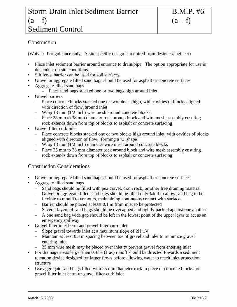
Construction (Waiver: For guidance only. A site specific design is required from designer/engineer) • Place inlet sediment barrier around entrance to drain/pipe. The option appropriate for use is
dependent on site conditions. • Silt fence barrier can be used for soil surfaces • Gravel or aggregate filled sand bags should be used for asphalt or concrete surfaces • Aggregate filled sand bags
– Place sand bags stacked one or two bags high around inlet • Gravel barriers
– Place concrete blocks stacked one or two blocks high, with cavities of blocks aligned with direction of flow, around inlet
– Wrap 13 mm (1/2 inch) wire mesh around concrete blocks – Place 25 mm to 38 mm diameter rock around block and wire mesh assembly ensuring
rock extends down from top of blocks to asphalt or concrete surfacing • Gravel filter curb inlet
– Place concrete blocks stacked one or two blocks high around inlet, with cavities of blocks aligned with direction of flow, forming a 'U' shape
– Wrap 13 mm (1/2 inch) diameter wire mesh around concrete blocks – Place 25 mm to 38 mm diameter rock around block and wire mesh assembly ensuring
rock extends down from top of blocks to asphalt or concrete surfacing Construction Considerations • Gravel or aggregate filled sand bags should be used for asphalt or concrete surfaces • Aggregate filled sand bags
– Sand bags should be filled with pea gravel, drain rock, or other free draining material – Gravel or aggregate filled sand bags should be filled only ¾ full to allow sand bag to be
flexible to mould to contours, maintaining continuous contact with surface – Barrier should be placed at least 0.1 m from inlet to be protected – Several layers of sand bags should be overlapped and tightly packed against one another – A one sand bag wide gap should be left in the lowest point of the upper layer to act as an
emergency spillway • Gravel filter inlet berm and gravel filter curb inlet
– Slope gravel towards inlet at a maximum slope of 2H:1V – Maintain at least 0.3 m spacing between toe of gravel and inlet to minimize gravel
entering inlet – 25 mm wire mesh may be placed over inlet to prevent gravel from entering inlet
• For drainage areas larger than 0.4 ha (1 ac) runoff should be directed towards a sediment retention device designed for larger flows before allowing water to reach inlet protection structure
• Use aggregate sand bags filled with 25 mm diameter rock in place of concrete blocks for gravel filter inlet berm or gravel filter curb inlet

Storm Drain Inlet Sediment Barrier (a – f) Sediment Control
B.M.P. #6 (a – f)
March 18, 2003 BMP #6-3
Inspection and Maintenance • Inspect barriers at least once a week and before and after each significant rainfall event (1:2
year storm and/or 40 mm in a 24 hour period) • Remove sediment build up after each storm event
– Sediment and gravel should not be allowed to accumulate on roads • Replace gravel if it becomes clogged with sediment • Remove all inlet protection devices when inlet protection is no longer required

Typical SectionB.M.P. #6a

Typical SectionB.M.P. #6b

Plan View and SectionB.M.P. #6c

Plan ViewB.M.P. #6d

Typical SectionB.M.P. #6e

Typical SectionB.M.P. #6f

Storm Drain Inlet Sediment Barrier (a – f) Sediment Control
B.M.P. #6 (a – f)
March 18, 2003 BMP #6-10
This page left blank intentionally.

Rock Check Dam Erosion Control and Sediment Control
B.M.P. #7
March 18, 2003 BMP #7-1
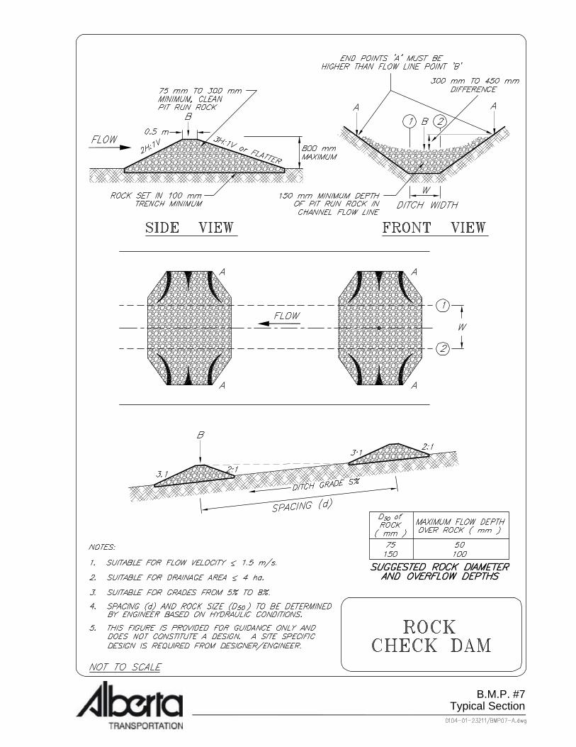
Description and Purpose • Small dam constructed of rock placed across steep channel • Decrease flow velocities to reduce erosion caused by storm runoff • Sediment laden runoff is retained allowing sediment to settle out Applications • Temporary or permanent measure • Reduces long steep grade to intervals of gentle grades between successive structures • Reduces flow velocities and kinetic energy to decrease erosion potential caused by runoff • Sediment laden runoff is retained behind structure allowing sediment to settle out • May be used in channels that drain 4 ha (10 ac) or less • May be used in steep channels where storm water runoff velocity is less than 1.5 m/s (5 fps) Advantages • More effective than straw bales for stabilizing medium to steep gradient ditches as a
permanent measure • Cheaper than using riprap armouring or gabion structures in a ditch • Easy to construct Limitations • Not appropriate for high flow velocity >1.5 m/sec; (use gabion structures for flow velocity
>1.5 m/sec) • Not appropriate for channels draining areas larger than 4 ha (10 ac) • Not to be placed in grass lined channels unless erosion is anticipated • Susceptible to failure if water undermines or outflanks structure

Rock Check Dam Erosion Control and Sediment Control
B.M.P. #7
March 18, 2003 BMP #7-2
Construction (Waiver: For guidance only. A site specific design is required from designer/engineer) • Excavate a trench key a minimum of 0.15 m in depth at the rock check structure location • Place non-woven geotextile fabric over footprint area of rock check • Construct structure by machine or hand • Structure should extend from one side of the ditch or channel to the other • Structure should be constructed so that centre of the crest is depressed to form a centre flow
width which is a minimum of 0.30 m lower than the outer edges • Height of structures should be less than 0.8 m in height to avo id impounding large volumes
of runoff • Downstream slope of the check dam should be 3H:1V (minimum) • Upstream slope of the check dam should be 2H:1V (minimum) Construction Considerations • Height and spacing between structures should be designed to reduce steep channel slope to
intervals of flatter gradient • Rock check structures should be constructed of free draining aggregate • Aggregate used should have a mean diameter (D50) of between 75 mm and 150 mm and must
be large enough to remain in place during high velocity flow situations. Maximum rock diameter should not exceed 150 mm if the structure is to be used as a sediment trap.
• If rock check structures are to be placed in channels with significant high flows, they must be properly designed for stone size and structure spacings
Inspection and Maintenance • Inspect barriers at least once a week and before and after each significant rainfall event (more
than 25 mm in a 24 hour period) • Remove sediment build up before it reaches one half the check structure height • Erosion repairs should be made immediately to prevent failure of the structure • Replace dislodged aggregate immediately with heavier aggregate or gabion structures Similar Measures • Sand bag check dam • Wood check dam • Straw bale check dam
Typical SectionB.M.P. #7

Rock Check Dam Erosion Control and Sediment Control
B.M.P. #7
March 18, 2003 BMP #7-4
This page left blank intentionally.

Sand Bag Check Dam Erosion Control and Sediment Control
B.M.P. #8
March 18, 2003 BMP #8-1
Description and Purpose • Small dam constructed with aggregate filled sand bags • Decrease flow velocities to reduce erosion caused by storm runoff • Sediment laden runoff is retained allowing sediment to settle out Applications • Temporary measure • May be used in small open channels that drain 2 ha (5 ac) or less • May be used in steeply graded channels to reduce gradient, especially in highly erodible soils
(sand and silt) • May be used until vegetation is established • May b used in temporary channels or ditches where short service life does not warrant
installation of erosion-resistant linings • Perimeter control Advantages • More effective than silt fences or straw bales for a temporary drop structure and sediment
trap for stabilizing major ditches • Cheaper than armouring entire channel or ditch • Easily constructed and reusable Limitations • Not appropriate for channels draining areas larger than 2 ha (5 ac) • Require extensive maintenance following high velocity flows associated with storm events • No filtering capabilities • Sand bags need to be placed by hand to avoid ripping bags during placement Construction (Waiver: For guidance only. A site specific design is required from designer/engineer) • Place sandbags by hand at check structure location • Check structure should extend from one side of the ditch or channel to the other • Structure should be constructed so that centre of the crest is depressed to form a centre flow
width which is a minimum of 0.30 m lower than the outer edges • Height of check structures should be less than 0.8 m to avoid impounding large volumes of
runoff • Downstream slope of the check dam should be 2.5H:1V (minimum) • Upstream slope of the check dam should be 1.5H:1V (minimum)

Sand Bag Check Dam Erosion Control and Sediment Control
B.M.P. #8
March 18, 2003 BMP #8-2
Construction Considerations • Height and spacing of check structures should be designed to reduce channel slope to
intervals of flatter gradient • Sandbags should only be filled ¾ full to allow bag to mould to contours, allowing continuous
contact between the bag and the soil Inspection and Maintenance • Inspect barriers at least once a week and before and after each significant rainfall event (more
than 25 mm in a 24 hour period) • Remove sediment build up before it reaches one half the check structure height • Erosion repairs should be made immediately to prevent failure of the structure • Replace dislodged or damaged bags immediately Similar Measures • Rock check dam • Wood check dam • Straw bale check dam

Log Check Dam Erosion Control and Sediment Control
B.M.P. #9
March 18, 2003 BMP #9-1
Description and Purpose • Small dam constructed of wood (logs/timbers) • Decrease flow velocities to reduce erosion caused by storm runoff • Used to reduce steeply graded channels to intervals of flatter gradients to reduce erosion flow
velocity and energy especially in highly erodible soils (sand and silt) • Sediment laden runoff is retained allowing sediment to settle out Applications • Temporary or permanent measure • Used in small open channels that drain 4 ha (10 ac) or less • Used in areas where logs/timber is readily available • Can be economical by reusing suitable timber material salvaged from clearing operations Advantages • More effective than silt fences or straw bales as temporary drop structure and sediment
entrapment for stabilizing major ditches • Cheaper than gabion structures depending on the availability of timber and its proximity to
the construction site Limitations • Not appropriate for channels draining areas larger than 4 ha (10 ac) • Not to be placed in grass lined channels unless erosion is anticipated • Labour intensive construction • Undermining and outflanking around the ends may occur if constructed improperly • Gaps between logs may allow sediment laden runoff to escape • Logs/timbers will decay and rot with time

Log Check Dam Erosion Control and Sediment Control
B.M.P. #9
March 18, 2003 BMP #9-2
Construction (Waiver: For guidance only. A site specific design is required from designer/engineer) • Embed ends of logs at least 0.5 m into channel or ditch bed • Ensure there are minimal gaps between logs • Install horizontal cross brace at top of the downstream side of structure to connect logs
together providing integral support • Structure should extend from one side of the ditch or channel to the other • Structure should be constructed so that centre of the crest is depressed to form a centre flow
width which is a minimum of 0.30 m lower than the outer edges • To avoid impounding large volumes of runoff, check structures should be less than 0.5 m in
height above the base of the ditch. Construction Considerations • Height and spacing of structures should be designed to reduce gradient to a flatter grade • Wood check dams placed in ditches with high anticipated flow velocity should have their
spacing and height design according to the anticipated hydraulic condition • Bracing should be installed to provide support to embedded logs Inspection and Maintenance • Inspect barriers at least once a week and before and after each significant rainfall event (more
than 25 mm in a 24 hour period) • Remove sediment build up before it reaches one half the check structure height • Erosion repairs should be made immediately to prevent failure of the structure • Replace dislodged, decayed, or damaged wood immediately Similar Measures • Rock check dam • Sand bag check dam • Straw bale check dam Design Considerations • Install splash pad (energy dissipater) on downstream side of structure to reduce erosion
potential of water overtopping the structure – Splash pad can be constructed of gravel, riprap, or bound woody debris

Typical SectionB.M.P. #9

Log Check Dam Erosion Control and Sediment Control
B.M.P. #9
March 18, 2003 BMP #9-4
This page left blank intentionally.

Synthetic Permeable Barrier Erosion Control and Sediment Control
B.M.P. #10
March 18, 2003 BMP #10-1
Description and Purpose • Double panel, low profile, uni-body porous synthetic barriers used to dissipate flow energy
and reduce velocity • Barriers of patented design constructed of lightweight and durable synthetic materials • May be used to create a grade break to reduce flow energy and velocities allowing some
sediment to settle out at the upstream barrier panel of the barrier structure • Can be used to dissipate flow energy and trap sediment during the period of revegetation;
should be removed at successful re-establishment of vegetation Applications • Temporary structure • May be placed across trapezoidal ditch to dissipate flow energy and reduce flow velocities • Can be used to supplement as grade breaks along ditch interval between permanent drop
structures along steep ditch grades • May be used as midslope grade breaks along contours of midslope or at toe of disturbed
slopes • Usually used as grade breaks along ditch (3 to 7% grade) in conjunction with erosion control
matting or non-woven geotextile as soil covering mattings; usually used in conjunction with permanent gabion structure (i.e. gabion) at steep grade (+6%) areas
• Designed to be reusable Advantages • Prefabricated • Reusable/moveable • More appropriate for installing at transition areas of changing grades of channels so that
hydraulic jumps (or change of flow regime from supercritical to subcritical) may be simulated to dissipate flow energy, thus minimizing erosion potential
• Provide portable drainage control for construction sites, ditches, channels, roads, slopes • The double panel porous barrier may allow significant energy loss as the flow of water
undergoes from supercritical flow to sub-critical flow from the upstream panel to the downstream panel with a more laminar flow evolving downstream and roughly parallel to the stream bed. Less turbulence and erosion energy may be created when compared with cascading, over-topping and tumbling flow from drop structures (i.e. gabions, check structures, straw bales)
• Barriers constructed of UV resistant material may be left in place for final channel stabilization as UV degradation is low
• Observed to enhance aggregation of silt material and to function as a sediment barrier with the formation of an earth block at behind the upstream barrier panel area; the downstream flow exiting at the downstream barrier panel may be of laminar nature and less erosive

Synthetic Permeable Barrier Erosion Control and Sediment Control
B.M.P. #10
March 18, 2003 BMP #10-2
Limitations • More appropriate for use as a grade break and may be installed between permanent drop
structures • Partially effective in retaining some sediment and reducing flow velocities • Less sturdy as drop structures in resisting high flow impact • Not to be designed as drop structures • Must be hand installed • Become brittle in winter and may be easily damaged by highway maintenance activities or by
public • At the time of deactivation of the structure after vegetation establishment, metallic anchor
pins, if not biodegradable, may require removal at time of completed revegetation • Stick-up of metallic anchor pin above ground may be a nuisance and, may cause damage to
human and maintenance equipment • The use of biodegradable anchor pins may be advisable Construction (Waiver: For guidance only. A site specific design is required from designer/engineer) • Install as per manufacturers recommended installation instructions • Normally installed in conjunction with erosion control matting in ditches and channels • Prepare soil surface • Install basal layer of erosion mat or geotextile fabric; key-in basal mat/fabric at upstream end • Place and anchor barrier panels with adequate pin anchors to basal soils Construction Considerations • Maintain intimate contact between base of barrier and soil with laying of basal matting/fabric
intimate to ground surface • Ensure side panel of barrier is extended to outer edges of channel to sufficient height to
provide freeboard of channel flow Inspection and Maintenance • Inspect barriers at bi-weekly intervals and after each significant rainfall event • Remove sediment build-up before it reaches one-half the check structure height • Do not damage barrier panel dur ing removal of sediment • Partial or non-removal of sediment build-up will create a non-permeable barrier and low
level earth mini-drop structure which will force water flow over-topping the barrier. The option of non-removal of sediments may be open to converting the sediment build-up into a "vegetated earth mini-drop structure" along the ditch with the non-removal of synthetic permeable barrier in-place. This will require topsoil and seeding (or intensive mulch seeding) to promote vegetation growth.

Synthetic Permeable Barrier Erosion Control and Sediment Control
B.M.P. #10
March 18, 2003 BMP #10-3
• If erosion is noted at the toe or upslope edges of the structure, hand regrading or suitable repairs should be made immediately to prevent failure of the structure
• Remove and deactivate at 1 year after vegetation is established Similar Measures • Silt fences or straw bales partially equivalent in retaining sediment • Brush or rock filter berms Design Considerations • Install synthetic permeable barrier along ditch interval between permanent drop structures
(i.e. gabion); can be economic alternative and supplemental to (i) total hard armouring of complete channel length, or (ii) high frequency of gabion installation required for high flow applications in steep ditch grade

Typical SectionB.M.P. #10

Straw Bale Check Dam Erosion Control and Sediment Control
B.M.P. #11
March 18, 2003 BMP #11-1
Description and Purpose • Small, temporary dam constructed of straw bales as drop structures placed across channels • Sediment laden runoff is ponded allowing sediment to settle out or is filtered through the
straw bale • Reduce steep grade to intervals of flatter grades between structures • Decrease flow velocities to reduce erosion potential caused by storm runoff Applications • Temporary measure • May be used in small open channels that drain 2 ha (5 ac) or less • May be used in channels with grade of less than 5% • May be used for flow velocities of 0.3 m/s or less • May be used until vegetation is established • May be used in temporary channels or ditches (offtakes) where short service life does not
warrant installation of erosion-resistant linings Advantages • Economical in areas where straw is readily available or within an economical hauling
distance • Biodegradable Limitations • Not appropriate for channels draining areas larger than 2 ha (5 ac) • Not appropriate for channels graded greater than 5% • Not appropriate for flow velocities greater than 0.3 m/s as straw bale can be damaged by high
flow impacts • Require extensive maintenance following high velocity flows associated with storm events • Not as robust as rock, wood, or sand bag check dams • Susceptible to failure if bales are not properly trenched and anchored thus allowing water to
undermine or outflank the structure • Service life is short • Must be installed by hand • Straw bale check structure should only be a maximum of one straw bale in height or 0.5 m
maximum

Straw Bale Check Dam Erosion Control and Sediment Control
B.M.P. #11
March 18, 2003 BMP #11-2
Construction (Waiver: For guidance only. A site specific design is required from designer/engineer) • Excavate a trench approximately 0.15 m deep with a width of two straw bales at the straw
bale check structure location • Place two rows of straw bales in excavated trench perpendicular to flow direction ensuring
bales are staggered so that no joints are aligned on the upstream and downstream rows. Ensure twine or wire is not in contact with the soil
• Infill all joints with straw • The centre of the crest of the check structure should be a centre flow width at least 0.15 m
lower than the outer edges along the channel walls • Drive two 50 mm square section wooden stakes 1.2 m long through each straw bale, ensuring
stake is embedded a minimum of 0.15 m into soil • Backfill and compact the upstream and downstream edges of the check structure to seat the
straw bales into the base of the ditch • Geotextile wrapping may be specified. The geotextile shall be pinned to the straw bale
subgrade. Construction Considerations • Height and spacing of structures should be designed to reduce gradient to a flatter grade • To avoid impounding large volumes of runoff, check structures should be a maximum of one
straw bale high • Straw bales should be:
– Machine-made – Weed free cereal crop straw such as wheat, oats, rye, or barley – Tightly compacted and bound with two rows of wire or synthetic string and shall show no
signs of weathering – No more than year old
Inspection and Maintenance • Inspect barriers at weekly intervals and after each significant rainfall event (1:2 year storm
and/or 40 mm rainfall over 24 hour duration) • Remove sediment build up before it reaches one half the check structure height • Erosion repairs should be made immediately to prevent failure of the structure • Replace damaged, decayed, or dislodged straw bales immediately • Straw bale check structure should be maintained until no longer required

Straw Bale Check Dam Erosion Control and Sediment Control
B.M.P. #11
March 18, 2003 BMP #11-3
Similar Measures • Rock check dam • Aggregate filled sand bag check structure • Log check dam

Typical SectionB.M.P. #11

Straw Bale Barrier Sediment Control
B.M.P. #12
March 18, 2003 BMP #12-1
Description and Purpose • A barrier of strawbale primarily used as a perimeter sediment control measure • May be used to intercept and retain sediment laden runoff allowing a portion of the sediment
load to be retained Applications • Temporary measure • Suitable for flow velocities of 0.3 m/s or less • Usually placed at 1m to 2 m offsets from toe of disturbed slopes • Size of drainage area should be no greater than 0.1 ha per 30 m length of straw bale sediment
barrier • Maximum flow path length upstream of barrier should be less than 30 m • Maximum slope gradient above the barrier should be no greater than 2H:1V • May be used in conjunction with filter fabric as external wrap to encapsulate the bale Advantages • Straw bales are biodegradable • Only requires one row of straw bales • Easier to install than other barriers and economical if straw bales are readily available Limitations • Not appropriate for flow velocities greater than 0.3 m/s • Require extensive maintenance following high velocity flows associated with storm events • Not as robust as earth berms or continuous berms • Susceptible to undermining and erosion damage if not properly keyed into substrate soil or if
joints are not completely infilled with straw • Short service life • Must be installed by hand • Not to be used on asphalt or concrete covered surfaces • Availability of appropriate bales may be limited in certain areas of the province • Maximum straw bale barrier height of one straw bale or 0.5 m maximum height

Straw Bale Barrier Sediment Control
B.M.P. #12
March 18, 2003 BMP #12-2
Construction (Waiver: For guidance only. A site specific design is required from designer/engineer) • Straw bale barrier should be located a minimum distance 1.8 m away from the toe of the
slope to provide adequate ponding and sedimentation area • Excavate a trench approximately 0.10 m deep with a width of one straw bale at the straw bale
barrier location • Place straw bales in excavated trench along contour, perpendicular to flow direction
– Ensure twine or wire is not in contact with the soil – Ensure straw bale is in continuous contact with base of trench – Ends of barrier should be angled upslope to form enclosure to contain runoff
• Infill all joints with loose straw • Drive two 50 mm by 560 mm section wooden stakes 1.2 m long through each straw bale,
ensuring each stake is embedded a minimum of 0.15 m into soil • Backfill and compact the upstream and downstream edges of the check structure to seat the
straw bales into the subgrade Construction Considerations • Maximum lengths of barriers should be 40 m, including ‘J-hook’ or ‘smile’ (similar to silt
fence in BMP #1) configuration, to allow escape route for excess runoff • Barrier should be placed far enough away from toe of slope to provide adequate ponding and
sedimentation area (minimum of 1.8 m away from toe of slope is recommended) • Ends of barriers should be angled upslope (in a ‘J-hook’ or ‘smile’ configuration) to form
enclosure to collect runoff • Straw bales should be:
– Machine-made – Weed free cereal crop straw such as wheat, oats, rye, or barley – Tightly compacted and bound with two rows of wire or synthetic string and shall show no
signs of weathering – No more than one year old
Inspection and Maintenance • Inspect barriers at least at weekly intervals and after each significant rainfall event (more
than 25 mm in a 24 hour period) • Remove sediment build up before it reaches one half the check barrier height • Erosion repairs should be made immediately to prevent failure of the structure • Replace damaged, decayed or dislodged straw bales immediately

Straw Bale Barrier Sediment Control
B.M.P. #12
March 18, 2003 BMP #12-3
Similar Measures • Silt fences • Continuous (earth-filled geotextile) berms • Earth Dyke Barrier

Typical SectionB.M.P. #12

Rolled Erosion Control Products (RECP) a) Channel Installation b) Slope Installation Erosion Control
B.M.P. #13
March 18, 2003 BMP #13-1
Description and Purpose • Biodegradable or synthetic soil coverings used for temporary or permanent protection of
disturbed soils at slopes and channels • Categories of Rolled erosion control products (RECP) can be:
– Erosion control blankets (ECB) (generally biodegradable and temporary) – Turf reinforcement mats (TRM) – Composite turf reinforcement mats (C-TRM)
• RECP may be manufactured of organic material, synthetic material, or as a composite of organic and synthetic materials
• Protect disturbed soils from raindrop impact and surface runoff erosion, increase water infiltration into soil, retains soil moisture and decreases evaporation loss
• Protect seeds from raindrop impact, runoff, and predators • Stabilizes soil temperature to promote seed germination and enhance vegetation growth Applications • Temporary or permanent measure • May be used to protect disturbed, exposed soils for cut or fill slopes at gradients of 2.5H:1V or
steeper • May be used on slopes where erosion potential is high
– Silts and sands have higher erosion potential than high plastic clays • May be used on slopes where vegetation is likely to be slow to develop • May be used to protect disturbed exposed soils in ditches and channels (with high flow
velocities) by providing additional tractive resistance cover in conjunction with a successful high density vegetative growth established
Advantages • Degree of erosion protection is higher, more uniform, and longer lasting than for sprayed-on
products (e.g. mulches) • Wide range of commercially available temporary (biodegradable) or permanent products Limitations • Non-performance of RECP may result from the following:
– Low density vegetation growth (beneath RECP) due to non-favorable weather and growth conditions (i.e. soil type, moisture, storm events at critical times). It is noted that values of tractive resistance of RECP products for vegetative growth may be generally tested in laboratory after a growth period (e.g. 3 months) under greenhouse growth conditions. The effectiveness of RECP, especially along channels , is very dependent on success of vegetation growth on site. It is important that the designer should assess the effectiveness of RECP in accordance with site, soil, terrain and vegetation growth conditions.

Rolled Erosion Control Products (RECP) a) Channel Installation b) Slope Installation Erosion Control
B.M.P. #13
March 18, 2003 BMP #13-2
– Hydraulic uplift of RECP and erosion of underlying soils can occur under rapid snow melt conditions when dammed up melt water generates a hydraulic head and high flow velocity generated in constricted snow melt channel. This situation can occur along steep channels interlaced with drop structures and with RECP lining installed in-between the drop structures. Ponding of melt water and non-anchored RECP joint areas allow flow entry beneath the RECP and generate hydraulic heads to uplift the RECP. This can occur along un-anchored edges of RECP at upper edges of ditch when snow melt occurs at tops of ditch and flow beneath the RECP. This is especially critical when underlying soil is easily erodible. (e.g. fine grained non-cohesive silty soils). It is important to trench-in and anchor the edges of the RECP installations and installed anchor pin (staples) at sufficient dense intervals.
– Ice buildup from groundwater seepage source can uplift and dislocate the RECP and causing flow beneath the RECP to erode the substrate soils. Winter ice accumulation may be related to groundwater regime and investigative design on subsurface drainage by a geotechnical engineer is required.
• Can be labour intensive to install • Must be installed on unfrozen ground • Temporary blankets may require removal before implementation of permanent measures • Rolled erosion control products (RECP) are not suitable for rocky sites • Proper surface preparation is required to ensure intimate contact between blanket and soil • Plastic sheeting can be used at sensitive slopes with precautions:
– Plastic sheeting RECP product can be easily torn, ripped, non-biodegradable, and should be disposed of in a landfill
– Plastic sheeting product, if used, results in 100% runoff, thus increasing erosion potential in downslope areas receiving the increased flow vo lumes
– Plastic sheeting should be limited to temporary covering of sensitive soil stockpiles or temporary covering of small critical unstable slope areas
Construction (Slopes) (Waiver: For guidance only. A site specific design is required from designer/engineer) • RECP should be installed in accordance with manufacturers directions • The following is a general installation method • Prepare surface and place topsoil and seed • Surface should be smooth and free of large rocks, debris, or other deleterious materials • Blanket should be anchored at top of slope in a minimum 0.15 m by 0.15 m trench for the
entire width of the blanket

Rolled Erosion Control Products (RECP) a) Channel Installation b) Slope Installation Erosion Control
B.M.P. #13
March 18, 2003 BMP #13-3
• The blanket should be rolled out downslope – (1) Where the blanket roll is not long enough to cover the entire length of the slope, a
minimum 0.15 m by 0.15 m check slot should be excavated at the location of the lap, and the downslope segment of blanket anchored in the check slot, similar to the method used for the top of the slope, or (2) when blankets, must be spliced down the slope, place blanket end over end (shingle style with approximately 0.10 m overlap. Staple through overlapped area at 0.3 m intervals.
– The upslope portion of blanket should overlap the downslope portion of blanket, shingle style, at least 0.15 m with staple anchors placed a maximum 0.3 m apart
– Adjacent rolls of blanket should overlap a minimum 0.1 m – Anchors should be placed along central portion of blanket spaced at 4/m2 minimum (0.5 m
spacing) for slopes steeper than 2H:1V and 1/m² (1 m spacing) for slopes flatter than 2H:1V
– Anchors along splices between adjacent rolls should be placed 0.9 m apart Construction (Channels) (For guidance only. A site specific design is required from designer/engineer) • A Blanket should be installed in accordance with manufacturers directions • The following is a general installation method
– Prepare surface and place topsoil and seed – Surface should be smooth and free of large rocks, debris, or other deleterious materials
– Begin by excavating a minimum 0.15 m deep and 0.15 m wide trench at the upstream end of channel and place end of RECP into trench – Use a double row of staggered anchors approximately 0.1 m apart (i.e. 0.2 m linear
spacing) to secure RECP to soil in base of trench – Backfill and compact soil over RECP in trench
– Roll centre RECP in direction of water flow on base of channel – Place RECP end over end (shingle style) with a minimum 0.15 m overlap downgrade
– Use a double row of staggered anchors approximately 0.1 m apart to secure RECP to soil
– Full length edge of RECP at top of sideslopes must be anchored in a minimum 0.15 m deep and 0.15 m wide trench – Use a double row of staggered staple anchors a maximum of 0.1 m apart (i.e. 0.2 m
linear spacing) to secure RECP to soil in base of trench – Backfill and compact soil over RECP in trench
– Overlap RECP on sideslopes (shingle style down channel) a minimum of 0.1 m over the centre RECP and secure RECP to soil with anchors spaced a maximum of 0.2 m apart
– In high flow channels, a check slot across the width of the channel is recommended at a maximum spacing of 10 m to anchor the ends of the RECP to the underlying soil – Use a double row of staggered staple anchors a maximum of 0.1 m apart (0.2 m linear
spacing) to secure RECP to soil in base of check slot – Backfill and compact soil over RECP in check slot

Rolled Erosion Control Products (RECP) a) Channel Installation b) Slope Installation Erosion Control
B.M.P. #13
March 18, 2003 BMP #13-4
– Anchor terminal ends of RECP in a minimum 0.15 m deep and 0.15 m wide trench – Use a double row of staggered anchors a maximum of 0.1 m apart (i.e. 0.2 m linear
spacing) to secure RECP to soil in base of trench – Backfill and compact soil over RECP in trench
Construction Considerations • Slopes should be topsoiled and seeded prior to placing RECP • Ensure blanket is in intimate contact with the soil by properly grading soil, removing rocks or
deleterious materials, prior to placing blanket • In channels, blankets should extend to above the anticipated flow height, with a minimum
0.5 m of free board • For turf reinforcement mat (TRM), blanket should be placed immediately after topsoiling • Blanket should be anchored by using wire staples, metal geotextile stake pins, or triangular
wooden stakes – All anchors should be a minimum of 0.15 to 0.2 m in length – For loose soils, use longer anchors
• Blankets should be placed longitudinal to direction of flow, with fabric not stretched but maintaining contact with underlying soil
• It is essential to understand product specifications and follow manufacturers instructions on installation methods
Product Quality Assurance/Quality Control (QA/QC) Certification RECPs should be certified by the supplier/manufacturer to ensure product performance and compliance with specified property requirements. A certificate for QA/QC testing of manufactured products is required. The performance and QA/QC testing should be carried out by reputable laboratories (e.g. TxDoT – Hydraulic and Erosion Control Laboratory OR equivalent laboratory) to ensure a commonly acceptable QA/QC standard. Dependent on product type and intended performance, the product information certificate should be provided by the product supplier/manufacturer to include the following: • Manufacturer's Certificate on • Performance specification
– Permissible Tractive Resistance (include testing methods and vegetative growth conditions)
– Permissible Flow Velocity (if available) – Longevity (for biodegradable or non-biodegradable products)
• Minimum Average Roll Values (MARVs) along with specified testing methods for – Physical properties
– Mass per unit area – Thickness – Tensile strength – UV Resistance

Rolled Erosion Control Products (RECP) a) Channel Installation b) Slope Installation Erosion Control
B.M.P. #13
March 18, 2003 BMP #13-5
– Other physical properties (for non-woven below Erosion Mat (if specified) – Grab tensile strength – Grab elongation – Puncture strength – Trapezoidal tear – UV Resistance
Inspection and Maintenance • Area covered with blankets should be regularly inspected/remediated, especially after periods
of severe rainfall or storm events, to check for blanket separation or breakage • Any damaged or poorly performing areas should be repaired/remediated immediately.
Regrading of the slope by hand methods may be required in the event of rill or gully erosion. • Inspection and maintenance should continue until dense vegetation is established • Areas with low vegetation density should be reseeded • After approximately one year, a top dressing of fertilizer may be applied to improve vegetation
cover and assist degradation of temporary blankets Similar Measures • Mulching (for slopes only) • Chemical stabilization (for slopes only, e.g. tackifiers) • Rip rap (primarily in channels) • Gabion mattresses (primarily in channels) Design Considerations • Assess hydraulic flow conditions and tractive stress on channel • Assess local soil, weather and growth conditions (favourable/non-favourable) for revegetation
(within 3 to 12 months) to allow a determination on use or non-use of RECP as a protective measure. If the revegetation conditions are assessed favourable, the use of RECP can be considered
• Assess suitability of a RECP product using tractive resistance data tested for (i) bare soil, and (ii) vegetated (a specified duration of growth period) condition
• It is noted that tractive resistance data are adopted as selection criteria of RECP and permissible velocity data can be provided for reference.

Typical SectionB.M.P. #13a

Typical SectionB.M.P. #13b

Rolled Erosion Control Products (RECP) a) Channel Installation b) Slope Installation Erosion Control
B.M.P. #13
March 18, 2003 BMP #13-8
This page left blank intentionally.

Riprap Armouring a) Slope Protection b) Channel Protection Erosion Control
B.M.P. #14 (a & b)
March 18, 2003 BMP #14-1
Description and Purpose • Large, loosely placed cobbles or boulders placed along channel banks or slopes to protect
underlying soil from erosion due to flowing water • Can protect slopes and channel banks against erosion Applications • Permanent measure • May be used on channel banks and slopes with flow velocities ranging from 2 m/s to 5 m/s
(dependent on rock size and thickness); appropriate for slopes that do not exceed 2H:1V • Riprap only needs to be placed at lower portion of channel section to the anticipated flow
height (mean annual peak flow) plus freeboard – Other form of soft armouring (RECP blankets, seeding) can be used to promote
vegetation to protect soil at upper portion of channel slopes, above riprap • Must be used in conjunction with a non-woven geotextile underlay acting as a filtration
separator with basal soil • For fluctuating high flow channel, the riprap should be underlain by a layer of granular filter
material for cyclic drawdown long-term performance with/without an extra layer of non-woven geotextile as underlay
Advantages • Easy to install and easy to repair • Very durable, long lasting, and virtually maintenance free • Flexible Limitations • Expensive form of channel lining and stabilization • Requires heavy equipment and transport of rock to site • May not be feasible in areas where suitable rock is not available • Riprap may have to be placed by hand • Normally 2 to 3 times riprap thickness is required in comparison with gabion mattress
thickness for equivalent protection performance under identical hydraulic conditions • Use of gabion is preferred at flow greater than 3 m/s due to larger nominal size of riprap and
thickness required for erosion protection during flow velocities of this magnitude.
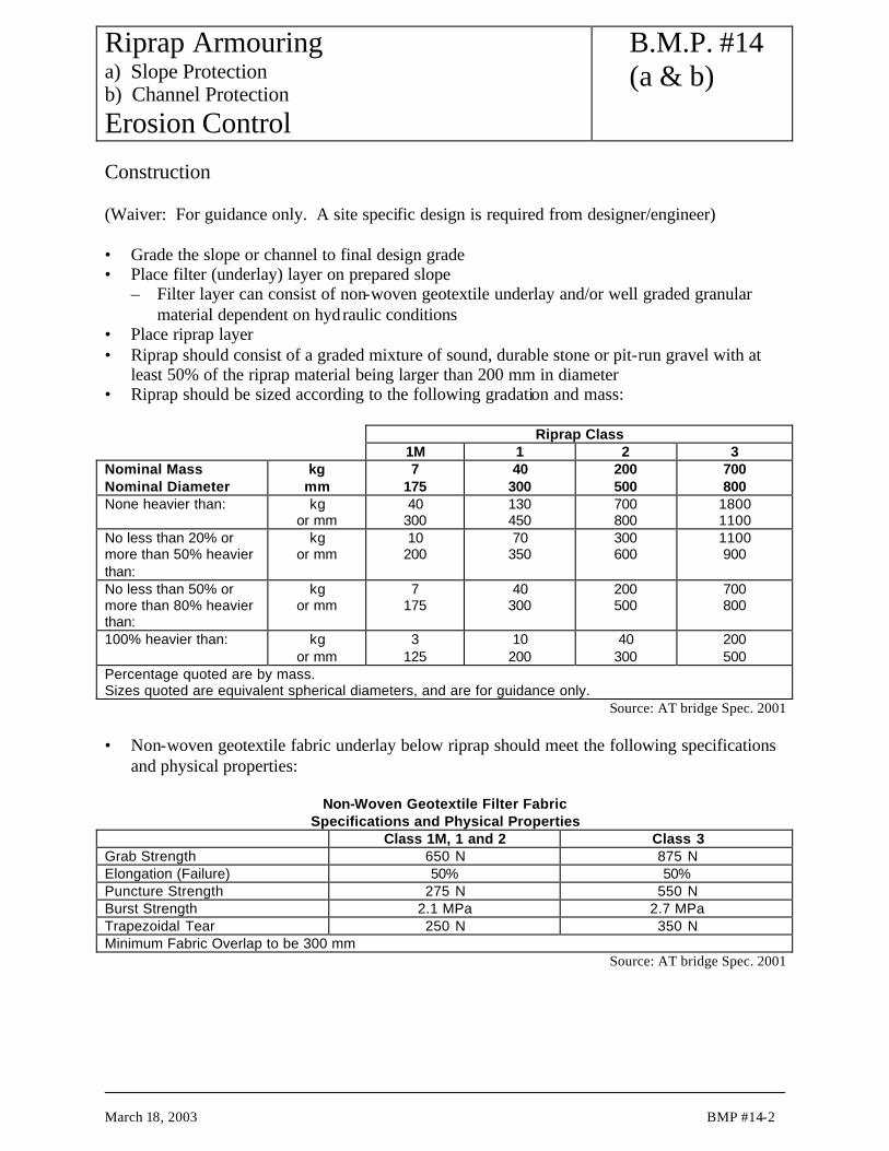
Riprap Armouring a) Slope Protection b) Channel Protection Erosion Control
B.M.P. #14 (a & b)
March 18, 2003 BMP #14-2
Construction (Waiver: For guidance only. A site specific design is required from designer/engineer) • Grade the slope or channel to final design grade • Place filter (underlay) layer on prepared slope
– Filter layer can consist of non-woven geotextile underlay and/or well graded granular material dependent on hydraulic conditions
• Place riprap layer • Riprap should consist of a graded mixture of sound, durable stone or pit-run gravel with at
least 50% of the riprap material being larger than 200 mm in diameter • Riprap should be sized according to the following gradation and mass: Riprap Class 1M 1 2 3 Nominal Mass Nominal Diameter
kg mm
7 175
40 300
200 500
700 800
None heavier than: kg or mm
40 300
130 450
700 800
1800 1100
No less than 20% or more than 50% heavier than:
kg or mm
10 200
70 350
300 600
1100 900
No less than 50% or more than 80% heavier than:
kg or mm
7 175
40 300
200 500
700 800
100% heavier than: kg or mm
3 125
10 200
40 300
200 500
Percentage quoted are by mass. Sizes quoted are equivalent spherical diameters, and are for guidance only.
Source: AT bridge Spec. 2001 • Non-woven geotextile fabric underlay below riprap should meet the following specifications
and physical properties:
Non-Woven Geotextile Filter Fabric Specifications and Physical Properties
Class 1M, 1 and 2 Class 3 Grab Strength 650 N 875 N Elongation (Failure) 50% 50% Puncture Strength 275 N 550 N Burst Strength 2.1 MPa 2.7 MPa Trapezoidal Tear 250 N 350 N Minimum Fabric Overlap to be 300 mm
Source: AT bridge Spec. 2001

Riprap Armouring a) Slope Protection b) Channel Protection Erosion Control
B.M.P. #14 (a & b)
March 18, 2003 BMP #14-3
Construction Considerations • Riprap should be placed in a uniform thickness across the channel so as not to constrict
channel width • Blasted rock is preferred (if available) • Riprap layer should be 1.5 to 2 times the thickness of the largest rocks used, 1.5 to 3 times
the thickness of the d50 material, and not less than 300 mm in thickness Inspection and Maintenance • Little maintenance is required • Periodic inspections to check for erosion of protected material or movement of riprap Similar Measures • Rolled erosion control products (RECP) well vegetated; not for use at severe flow and high
velocity areas • Gabion mattresses

Typical SectionB.M.P. #14a

Typical SectionB.M.P. #14b

Riprap Armouring a) Slope Protection b) Channel Protection Erosion Control
B.M.P. #14 (a & b)
March 18, 2003 BMP #14-6
This page left blank intentionally.

Cellular Confinement System (Geocomposites) Erosion Control
B.M.P. #15
March 18, 2003 BMP #15-1
Description and Purpose • 3-dimensional, plastic matting with open cells filled with topsoil or aggregate • 3-dimensional structure stabilizes cut or fill slopes • Cells confine infilled topsoil or aggregate and protect root zone while permitting surface
drainage Applications • Permanent measures • May be used with granular infill on cut or fill slopes up to a slope of 1H:1V • May be used with granular infill on slopes and in ditches where flow velocities are 3 m/s or
less • May be used as a flexible channel lining • May be used in temporary low-water stream crossing as granular pad for stream fording • Matting is light, expandable, and easy to transport and place • Use of native fill materials reduces costs; local granular fill is preferred Limitations • Not widely used in Alberta highway construction
– Availability can be limited, therefore expensive in some areas • Installation can be labour intensive • Not to be used on slopes steeper than 1H:1V • Slopes of 1H:1V can be hazardous to work on Construction (Waiver: For guidance only. A site specific design is required from designer/engineer) • Cellular Confinement System should be installed in accordance with manufacturer's
directions • The following is a general installation method
– Slope should be graded to design elevations and grades – Rocks or other deleterious debris should be removed from matting location – Matting should be installed in a trench as deep as the matting is thick, extending 0.6 to
1.2 m beyond crest of slope, and matting should be installed so that the top of the matting is flush with surrounding soil – Every other cell along crest of slope should be anchored to soil using ‘J’ pins or other
suitable sturdy anchoring device – The matting should be rolled out downslope – Where the blanket roll is not long enough to cover the entire length of the slope, the
downslope section of matting should be butt-jointed to the upslope section and secured using staples, hog rings, or other suitable fasteners

Cellular Confinement System (Geocomposites) Erosion Control
B.M.P. #15
March 18, 2003 BMP #15-2
– Adjacent rolls of matting should be butt-jointed and secured using staples, hog rings, or other suitable fasteners
– Anchors are placed at 1 m intervals down the slope – Additional anchors may be required to ensure matting is in intimate contact with soil – Additional anchors may be required along edges of matting
– Backfilling should start at the crest of the slope and proceed downslope – For topsoil, overfill cells approximately 25 to 50 mm and lightly compact so that top
of topsoil is flush with matting – For granular fill, overfill cells approximately 25 mm and tamp compact so that top of
fill is flush with matting – Seeding should be applied after fill placement
Construction Considerations • Properly grading soil surface, removing rocks or deleterious materials, prior to placing
matting to ensure matting is in intimate contact with the soil • Matting should be placed longitudinal to direction of flow or downslope • Use only a single layer of matting • Matting elevation should be subexcavated to thickness of matting so that the top of the
matting is flush with the adjacent terrain • Infill from top of slope ensuring placement height of fill into cellular mat is less than 1 m Inspection and Maintenance • Area covered with matting should be regularly inspected, especially after periods of heavy
rainfall storms to check for damage or loss of material – Any damaged areas should be repaired immediately
• Temporary inspection should continue until vegetation is established – Areas where vegetation fails to grow should be reseeded immediately
• If matting is broken or damaged and washout of the underlying soil occurs, the matting should be repaired or replaced after regrading the slope
Similar Measures • Rolled erosion control products (RECP) • Rip rap armouring

Typical SectionB.M.P. #15

Cellular Confinement System (Geocomposites) Erosion Control
B.M.P. #15
March 18, 2003 BMP #15-4

Gravel Blankets Erosion Control and Sediment Control
B.M.P. #16
March 18, 2003 BMP #16-1
Description and Purpose • Crushed stone or gravel layer/blanket placed directly to erodible slopes under influence of
groundwater seepage piping erosion as well as surface water erosion • For remediation of unstable slope caused by piping loss of soil resulting from strong
groundwater exit gradient and subground erosion. • To secure the soil, reduce erosion, and provide continuous all-weather protection • Protects piping erosion of underlying soil as well as surface erosion from raindrop impact,
and sheet flow • Prevents transportation of soil from areas subject to groundwater seepage • Acts as a filter to minimize seepage erosion of soil from areas subjected to groundwater
seepage • Provides hard armour protection for slope Applications • Permanent measure • May be used on highly erodible slopes (silt and sand) that cannot be effectively stabilized by
vegetative methods • May be used when cover must be placed immediately as a toe filter to minimize seepage
erosion due to strong groundwater seepage exit on cut slopes • Must be used in conjunction with non-woven geotextile fabric underlay for areas of high
groundwater seepage exits • In most situations, subsurface drains are designed in conjunction with gravel blankets. Advantages • Easily constructed and implemented Limitations • Must be designed by qualified geotechnical personnel • Requires equipment and transport of gravel to site • May be unfeasible in areas where gravel is not readily available • Areas of high groundwater seepage may require other subsurface drainage measures

Gravel Blankets Erosion Control and Sediment Control
B.M.P. #16
March 18, 2003 BMP #16-2
Construction (Waiver: For guidance only. A site specific design is required from designer/engineer) • Place non-woven geotextile as underlay, as a general good practice to provide filtration
separator with subgrade soils • Place gravel • Grade gravel blanket to design thickness Construction Considerations • Aggregate must be placed evenly over slope • On slopes of highly erodible materials (silt and sand) gravel blanket thickness should be
0.4 m minimum and should be assessed by a qualified geotechnical engineer • Generally for slope protection for subground piping erosion, the blanket can be constructed
of clean pit run gravel (Designation 6 Class 125 AT Specifications) to 0.4 m thickness
Metric Sieve Size (µµm) Percent Passing 125,000 100 50,000 5-100 25,000 38-100 16,000 32-85 5,000 20-65 315 6-30 80 2-10
Inspection and Maintenance • Inspect gravel blanket after significant storm events and repair any damaged or wash out
sections immediately – Sections washed out may need to be regraded prior to replacing gravel and geotextile
Similar Measures • Subdrain systems

Energy Dissipators a) for Culvert Outlet b) for Trough at Bridge Headslope Erosion Control
B.M.P. #17 (a & b)
March 18, 2003 BMP #17-1
Description a) Hard armour (rip rap, gravel, sand bags, concrete) placed at pipe outlets, in channels, and at
downstream side of check structures to reduce velocity and dissipate energy of concentrated flows (BMP 17a)
b) Standard Drain Trough Terminal Protection Structure generally used at bridge headslope (BMP 17b)
• Minimizes scour at flow impact location with dissipated flow energy Applications • Permanent measure • May be used at outlets of pipes, drains, culverts, conduits, or channels with substantial flows • May be used at slope drain outlets located at the bottom of mild to steep slopes • May be used where lined channels discharge into unlined channels • May be used as splash pad on downstream side of gabions, check structures, berms, barriers,
and silt fences to prevent erosion caused by overtopping of structure Advantages • Reduces flow energy in a relatively small area Limitations • Small rocks or stones can be dislodged during high flows • Grouted rip rap may breakup due to hydrostatic pressure, frost heave, or settlement • May be expensive if construction materials (rip rap, gravel, or concrete) is not readily
available • May be labour intensive to place and construct • Extreme flow velocities may require paved outlet structures, stilling basins, plunge pools,
drop structures, baffles, or concrete splash pads which will require special design by qualified personnel. Energy dissipators constructed of rip rap may not be adequate for extreme flow velocities

Energy Dissipators a) for Culvert Outlet b) for Trough at Bridge Headslope Erosion Control
B.M.P. #17 (a & b)
March 18, 2003 BMP #17-2
Construction (Waiver: For guidance only. A site specific design is required from designer/engineer) • Grade the area to final design grades and elevations • Sub-excavate energy dissipator location to thickness of energy dissipator • Place filtration bedding material on base of excavation
– Bedding can be comprised of well graded sand and gravel or non-woven geotextile – Acts as separating filter between fine grained subgrade and riprap size energy dissipator
material • Place energy dissipator material (rip rap, gravel, sand bags, concrete) over filtration bedding
material – Top of energy dissipator should be flush with surrounding grade
Construction Considerations • Length of energy dissipator (La) at outlets shall be of sufficient length to dissipate energy
– La = 4.5 x D (where D is the diameter of the pipe or channel at the outlet) – Energy dissipator should extend upstream of the outlet approximately a minimum
distance of 0.5 x D • Width of energy dissipator (Wa) at outlets shall be of sufficient width to dissipate energy
– Wa = 4 x D • Thickness of energy dissipator (da) at outlets shall be of sufficient thickness to dissipate
energy – da = 1.5 x maximum rock diameter (with a minimum thickness of 0.30 m)
• Energy dissipator (splash pad, apron) shall be set at zero grade and aligned straight, with the direction of flow at the outlet
• Bedding (filtration) layer can comprise either non-woven geotextile or a minimum of 0.15 m well graded sand and gravel layer
• Energy dissipator should be constructed of well-graded rip rap – Minimum d50 = 150 mm. Preferable d50 = 300 mm – Minimum thickness = a) 1.5 x d50 or b) 0.30 m to 0.45 m thickness. (a or b whichever is
greater) • Energy dissipator shall be designed to accommodate a 10-year peak runoff or the design
discharge of the upstream channel, pipe, drain, or culvert, whichever is greater • The energy dissipator shall be constructed flush with the surrounding grade and shall be
directly in line with direction of outlet flow

Energy Dissipators a) for Culvert Outlet b) for Trough at Bridge Headslope Erosion Control
B.M.P. #17 (a & b)
March 18, 2003 BMP #17-3
Inspection and Maintenance • Periodic inspections to check for damage should occur at least once a month, or after storm
events (1:2 year storm and/or 40 mm rainfall over 24 hour duration) • Any damage should be repaired immediately Similar Measures • Gabion mattresses

Typical SectionB.M.P. #17a

Typical SectionB.M.P. #17b

Energy Dissipators a) for Culvert Outlet b) for Trough at Bridge Headslope Erosion Control
B.M.P. #17 (a & b)
March 18, 2003 BMP #17-6
This page left blank intentionally.

Sediment Traps and Basins a) Riser Outlet Option b) Permeable Rock Berm Outlet Option Sediment Control
B.M.P. #18 (a & b)
March 18, 2003 BMP #18-1
Description and Purpose • Low height dam enclosure for impoundment of sediment laden storm water, sedimentation of
silt size particles and release of treated storm water • Used to trap sediment laden run off and promote settlement of sediment prior releasing to
enter downstream or watercourses • Constructed by excavating a pond or building embankments above the original ground
surface • Sediment traps and basins can be divided on size of pond impoundment enclosure
– Basin (Type I) for pond area ≥500 m² – Trap (Type II) for pond area ≤500 m²
Applications • Permanent measure • Used at terminal or selective intermediate points of concentrated runoff for impoundment of
runoff and sedimentation of silt prior to release of treated runoff downstream • Used as sedimentation control measure at perimeter of construction sites where sediment
laden run off may enter watercourses, storm drains, or other sensitive areas • Used where there is a need to impound a significant amount of sediment from significant
areas of land disturbance • Sediment basins (Type I) used for disturbed drainage areas greater than 2.0 ha • Sediment traps (Type II) used for disturbed drainage areas of 2.0 ha, or less • Where practical, contributing drainage areas should be subdivided into smaller areas and
multiple sedimentation impoundment installed Advantages • High capacity of runoff impoundment and more efficient means of sedimentation necessary
along perimeters of construction sites with high risk sensitive environmental areas and watercourses
• Sediment can be cleaned out easily • Robust • Can be deactivated easily by breaching the enclosure dyke

Sediment Traps and Basins a) Riser Outlet Option b) Permeable Rock Berm Outlet Option Sediment Control
B.M.P. #18 (a & b)
March 18, 2003 BMP #18-2
Limitations • Requires specialized design by qualified personnel • Sediment traps and basins do not remove 100% of the sediment; net efficiency for
sedimentation of silt may be around 50% dependent on design • Anticipated service life of 3 years or longer due to possible clogging of outlets in the
long-term • Sedimentation traps and basins with a riser outlet should have an auxiliary spillway with
adequate erosion protection to permit overflow in the event that the riser pipe outlet clogs during a storm event
• For drainage areas greater than 40 ha, multiple basins may be required • Efficiency on sedimentation is very dependent on surface area; sediment basins require large
surface areas to permit settling of sediment • Fences and signage may be required to reduce danger to the public • May provide breeding habitat for mosquitoes and other pests • Sediment traps only remove medium and large diameter silt particles and upstream erosion or
sediment control measure is required to reduce the amount of sediment laden to the runoff at downstream sensitive areas
• Periodic removal of sediment build up is required Construction (Waiver: For guidance only. A site specific design is required from designer/engineer) • The consequences of failure for any water retaining structure will determine the level of
effort in the design and construction phases. The construction guidelines presented herein are minimum requirements. A geotechnical engineer should design water retaining structures if the consequences of failure warrant.
• All footprint area for embankment dyke should be stripped of vegetation, topsoil, and roots to expose mineral subgrade soils
• Embankment fill material should be clean mineral soil with sufficient moisture to allow proper compaction – Fill should be placed in lifts not exceeding 150 mm in compacted thickness and should be
compacted to a minimum of 95% Standard Proctor maximum dry density (SPD) • The main outlet structure should be installed at farthest possible point from inlet
– Outlet should be placed on firm, smooth ground and should be backfilled to 95% SPD – Proper inlet and outlet protection should be installed to protect from scour – Outlet pipe should consist of corrugated steel pipe to protect (against pinching and
blockage) • The embankment should be topsoiled, seeded or protected with gravel or riprap immediately
after construction • Construct an emergency spillway to accommodate flows not carried by the principle outlet

Sediment Traps and Basins a) Riser Outlet Option b) Permeable Rock Berm Outlet Option Sediment Control
B.M.P. #18 (a & b)
March 18, 2003 BMP #18-3
– Emergency spillway should consist of an open channel (earth or vegetated) over native undisturbed soil (not fill)
– If spillway is elevated, it should be constructed of rip rap – Spillway crest should be depressed at least 0.15 m below embankment
Construction Considerations • Preferable to strip to mineral soil only along the footprint area required for dyke construction;
can leave pond floor centre area cleared but unstripped • Can be constructed by excavating, constructing embankments, or a combination of the two
methods • Baffles should be provided to prevent short-circuiting of flow from inlet to outlet • Construct sediment ponds and basins at site perimeter and environmentally sensitive areas
prior to wet season and construction activities • Sediment pond/basin bottom should be flat or gently sloping towards outlet • Dyke slopes should not be steeper than 2H:1V and should be compacted • Basins should be located where:
– Low embankment can be constructed across a swale or low natural terrain – It is accessible for maintenance work, including sediment removal
Inspection and Maintenance • Regular inspection is required to identify seepage, structural soundness, outlet damage or
obstruction and amount of sediment accumulation • Inspections should be performed weekly and after significant storm events (1:2 yr storm
and/or 40 mm rainfall in 24 hours) • Sediment should be removed upon reaching 1/2 height of the containment berm or within
0.4 m of crest of embankment • Sediment traps may be deactivated or removed after vegetation of previously disturbed
upstream areas has been established

Sediment Traps and Basins a) Riser Outlet Option b) Permeable Rock Berm Outlet Option Sediment Control
B.M.P. #18 (a & b)
March 18, 2003 BMP #18-4
Design Considerations • The design can consist of (1) a riser outlet option or (2) a permeable rock berm outlet option.
(The permeable rock berm outlet option is preferable for Alberta highway construction) • Minimum particle size for rip-rap rock shall be 200 mm • If the design of a riser outlet is utilized
– Main outlet pipe shall be fabricated from corrugated steel pipe conforming to CSA standard CAN 5-G401-M81 or the latest revision thereof
– Outlet pipe shall consist of a horizontal pipe welded to a similar vertical riser at a 45E mitre joint
• Close to the base of the riser pipe, a 100 mm diameter hole shall be fabricated and a mesh with 12 mm square openings tack welded over the hole as a screen – A similar hole shall be provided along the riser pipe immediately above the elevation of
the maximum sediment buildup (usually 0.4 m below crest of embankment)

Typical SectionB.M.P. #18a

SEDIMENT-LADENRUNOFF WATER
CONTAINMENT DYKE CONSTRUCTED FROM BORROW OREXCAVATED MATERIAL TO CREATE AN AVERAGE PONDDEPTH OF 1.2 m OVER A GENERAL IMPOUNDMENT AREA
OVERFLOW ANDTREATED RUNOFF
(SEE FIGURE CDETAILS FOR SECTION A-A')
We
L1. CONTRIBUTING RUNOFF AREA SHOULD BE OR SMALLER THAN 2.0 ha.
2. EFFECTIVENESS APPROPRIATE FOR REMOVING MEDIUM TO COARSE SILT PARTICLES SUSPENDED IN RUNOFF.
3. L W RATIO 3:1 CAN BE APPROPRIATE.
EARTH DYKE
ROCK OUTLET BERM
A A'
NOTES:
e
4. We = 8 m MINIMUM BOTTOM WIDTH.
Figure B Type II Containment Structure ( Sediment Trap )Plan View
Figure A Type 1 Sedimentation Pond Containment Structure (Sediment Basin)
OVERFLOW ANDTREATED RUNOFF
MINIMUM FREEBOARDOF 200 mm
1000 mmMINIMUM
MINIMUM OF 200 mmDEPRESSION
O U T L E T F R O N T V I E W
2. EFFECTIVENESS APPROPRIATE FOR REMOVING MEDIUM TO COARSE SILT
3. FLOW PATH L = L + L + L ; FLOW WIDTH W = 6 m MINIMUM
L
We
We
We
SEDIMENT-LADEN RUNOFF WATERFROM INLAND DITCH OUTFALL
TOE OF BERM AT MINIMUM 5 m SETBACKDISTANCE FROM TOP OF BANK
EARTHEN BERM TO DIVERT RUNOFF
EARTH DYKE CONSTRUCTED FROMBORROW OR EXCAVATED MATERIALTO FORM POND ENCLOSURE HAVING ANAVERAGE UNIFORM DYKE HEIGHT OF 1200 mm
ROCK OUTLET BERM (SEE FIGURE C)
1200 mm
2H:1V SLOPE FOREARTH DYKE
OUTLET WIDTHMINIMUM OF 2000 mm
1000 mmMINIMUM
0.6 m2H:1V 3H:1V
S E C T I O N A - A'
A'
A
FLOW
GRAVELOUTLET BERM
OR OTHER MATERIAL (PLYWOOD
DESIGN FULL POND LEVEL
1000 mm0.3 m THICK 2H:1V
200 mm BELOW CREST OFADJOINING EARTH DYKE
3H:1V1.5H:1V
M1 CLEAN RIPRAP (200 mm D )50
GEOTEXTILE(A.O.S.= 0.15 mm)
APRON TO PROTECT DISCHARGE
"BIG O" PERFORATED PIPE2 NOs. 100 mm DIA SOCKED
1 m LENGTH SOLIDCSP OUTLET PROTECTION
AREA AGAINST EROSION
2 m 3 m
T = 2m
0.5 m
( 3 m WIDE )
D 25 mm DIA. (Des 8 Class 25) FILTER GRAVEL
NOTES:
Plan View
Figure C Section A-A' - Details for Sedimentation Pond
PARTICLES SUSPENDED IN RUNOFF.
FOR PERFORATED PIPE
EARTH DYKEat 2H:1V
e1
1
L3
L 2
MINIMUM
RANDOM RIPRAP (250 mm D )
50
NON-WOVEN
0.3 m THICK
NOTE: A.O.S. = APPARENT OPENING SIZE
Outlet
Inlet
4. PROVIDE 1 TO 2 m (1 TO 2% GRADE) ELEVATION DROP BETWEEN INLET AND OUTLET GRADES.
D
D
D
1.2 m
1 m2H:1V 2H:1V
E A R T H D Y K E (D)
EARTH BERM
2.4 m 2.4 m
D = 5.8 m
1 m
5. SHAPE OF POND TO CONFORM TO TOPOGRAPHY WITH OUTLET AT MINIMUM 5 m
6. CONSTRUCTION TO ENSURE SWALES AND BAFFLES ARE TO CHANNEL WATER INTO THEPROPOSED SEDIMENTATION PONDS.
(Permeable Structure with Rock Filter Barrier and Perforated Pipe )
We3
x
NON-WOVEN GEOTEXTILE FENCE(SAME CONSTRUCTION AS SILT FENCE (BMP#1))
OPTIONAL DOUBLE GABION DROP STRUCTURE(BMP 2c) TO DISSIPATE RUN-OFF ENERGYPRIOR TO IMPOUNDMENT OF RUN-OFF
5. NON-WOVEN GEOTEXTILE FABRIC WITH A0S 0.15mm.<
PRIOR TO IMPOUNDMENT OF RUN-OFF(BMP 2c) TO DISSIPATE RUN-OFF ENERGYOPTIONAL DOUBLE GABION DROP STRUCTURE
SOURCE: 1) FIFIELD (2001) FOR STRUCTURE PLAN2) EBA FOR OTHER DESIGN DETAILS
BOARD SECURED TO 4"x4" POST)
1. CONTRIBUTING RUNOFF AREA CAN BE LARGER THAN 2.0 haBUT LESS THAN 40.0 ha.
2 3
(SIMPLIFIED)
50
D
FROM TOP OF BANK.
xxxxxx
xxxxxxx
xxxxxxx
xxxxxxx
2
23 eW
Typical SectionB.M.P. #18b

Slope Drains (Temporary Pipes) a) Slope Drain b) Overside Drain Erosion Control
B.M.P. #19
March 18, 2003 BMP #19-1
Description and Purpose • Heavy duty, flexible pipe "Big O" that carries water from top to bottom of fill or cut slope to
prevent concentrated water flowing downslope and eroding face of slope Applications • Temporary or permanent measure • Used on cut or fill slopes where there is a high potential for upslope runoff waters to flow
over the face of the slope causing erosion, especially at areas where runoff converges resulting in concentrated runoff flows (e.g. possible breach of low catchwater ditch at top of a cut slope)
• Used in conjunction with some form of water containment or diversion structures, such as diversion channels, berms, or barriers, to convey upslope runoff water and direct water towards slope drain
Limitations • Pipes must be sized correctly to accommodate anticipated flow volumes • Water can erode around inlet if inlet protection is not properly constructed • Erosion can occur at base if outlet protection or energy dissipator is not constructed • Slope drain must be anchored securely to face of slope Construction (Waiver: For guidance only. A site specific design is required from designer/engineer) • Construct diversion or intercept channel, ditch block, barrier, or other inflow apron structure
at crest of slope to channel flow toward the slope drain inlet • Install slope drain through inlet berm or barrier with a minimum of 0.45 m of soil cover
above top of drain pipe to secure the inlet – Install scour inlet protection (such as rip rap, sand bags)
• Install energy dissipator (such as rip rap, gravel, concrete) at downslope outlet end of slope drain – Outlet must not discharge directly onto unprotected soil
• Secure the pipe from movement by tying to steel anchor stakes, hold-down grommets, or other approved anchor method – Space anchors on each side of drain pipe at maximum 3 m intervals along entire length of
drain pipe

Slope Drains (Temporary Pipes) a) Slope Drain b) Overside Drain Erosion Control
B.M.P. #19
March 18, 2003 BMP #19-2
Construction Considerations (For guidance only) • Use coiled drain pipe for low flows only • If constructing inflow apron at crest of slope out of sandbags, only fill each sandbag ¾ full,
this will allow sandbag to be flexible enough to mould around drain pipe and remain in continuous contact with the ground
• Several slope drains may be required if upslope drainage areas are too large for one drain pipe
Size of Slope Drain
Maximum Drainage Area (ha) Pipe Diameter (mm) 0.2 300 0.6 450 1.0 530 1.4 600 2.0 760
Inspection and Maintenance • Inspect slope drains at least once per week, or after significant storm events (1:2 year storm
and/or 40 mm precipitation in 24 hours) • Repair any damaged section of pipe immediately • If evidence exists of pipe movement, install additional anchor stakes to secure and anchor at
zones of movement • Remove sediment from upslope inflow apron area after each storm event otherwise either
downslope sediment transport will occur or cause the drainpipe to be plugged which could result in overtopping of inflow apron structure and sheet flow over slope face.
Similar Measures • Rock lined channel • Permanent Pipe (slope drains)
– Corrugated steel pipe (CSP) downdrain (AT Drawing No. CB-6 2.4 M17) – Half-round corrugated steel (1/2 CSP) downslope drain (AT Drawing No. CB-6 2.4 M4)
for low flow areas such as bridge headslopes

Typical SectionB.M.P. #19a

Typical SectionB.M.P. #19b

Groundwater Control (Subsurface Drains or Finger Drains) Erosion Control
B.M.P. #20
March 18, 2003 BMP #20-1
Description and Purpose • Drains that intercept and collect subsurface groundwater and divert it from slope, thus
lowering groundwater table to minimize piping erosion reducing seepage flow on slopes and increase slope stability
• Relief drains (perforated finger-drains or French drains) to mitigate high groundwater table to minimize piping erosion
Applications • Permanent measure • Used on cutslopes where groundwater seepage exits on slope face Limitations • Must be designed by a geotechnical engineer • Can be expensive to install • Plugging of drainage outlet can be detrimental to cause build-up of pore pressure; it is
mandatory to protect the outlet area to ensure free draining condition Construction (Waiver: For guidance only. A site specific design is required from designer/engineer) • Excavate trench at subsurface drain location • Install drain pipe • Backfill with clean, coarse drainage gravel and/or non-woven geotextile fabric to provide
filtration separation with adjacent soils Construction Considerations • When signs of seepage and unstable excavation slope are encountered at excavations, it is
advisable to install trench protection measures for safety (i.e. trench box) • Carry out work as soon as possible to mitigate seepage damage, soil loss and deterioration of
unstable slope • Excavate and install drains to the grade and spacings according to design and
recommendations made by the geotechnical engineer • Protect outlet of drainage with sturdy pipe to ensure free draining condition

Groundwater Control (Subsurface Drains or Finger Drains) Erosion Control
B.M.P. #20
March 18, 2003 BMP #20-2
Inspection and Maintenance • Drains installed below grade will require manhole at frequent intervals (100 m maximum) to
facilitate inspection and maintenance • Flushing and maintenance clean out of drains can be carried out through manhole locations

Offtake Ditch (Intercept Ditch) Erosion Control
B.M.P. #21
March 18, 2003 BMP #21-1
Description and Purpose • Channels or swales commonly located along the crest of cuts slopes to intercept and convey
runoff away from flowing down a newly excavated bare soil slope and to minimize erosion of slope from overlanding sheet flow
• Can be tied to outfall to slope drains (or downdrains) which carry water from higher slope elevations to lower elevation of a slope
Applications • Permanent measure • Effective method of intercepting runoff to avoid excessive sheet flow over slope and causing
erosion, especially on cut slopes in highly erodible soils (sand and silt) • Can be used in conjunction with slope drains which was installed down a large cut slope • May be lined with vegetation, rip rap, erosion control blankets, or some other erosion
protection measure, but this requirement may be appropriate only at highly sensitive and high risk environmental areas
• Can be used in conjunction with sediment control measures, such as check structures or permeable synthetic barriers as normal channel design, but this requirement may be appropriate only at highly sensitive and high risk environmental areas
Limitations • Ditch may require lining to minimize soil erosion from concentrated flow • Ditch may require design by qualified personnel if flow velocities and/or volumes are large • Channel must be graded to maintain adequate depth, positive drainage to avoid ponding and
breaching of channel flow, which may lead to overtopping of the channel to result flow to cause in downslope erosion
• Removal of sediment build up and ditch maintenance may be difficult due to limited access space as offtake ditches are commonly constructed at crest of slopes

Offtake Ditch (Intercept Ditch) Erosion Control
B.M.P. #21
March 18, 2003 BMP #21-2
Construction (Waiver: For guidance only. A site specific design is required from designer/engineer) • Use backhoe to form ditch a minimum offset distance of 2 m between crest of highway slope
and top of offtake ditch sideslope, thus providing a dyke width of 1 m – Place and compact excavated soil to form a dyke between crest of highway slope and
offtake ditch channel to provide adequate depth (1 m) of the offtake ditch – The consequence of failure on this dyke will determine the level of compaction effort
required – Sideslopes of ditch should not be steeper than 2H:1V (depending upon material type) – Depth of ditch (from base of ditch to top of embankment) should be a minimum of 1 m in
depth; width of ditch should be 1 m minimum – Ditch grade should be graded a minimum of 1% to promote positive drainage and outfall
Construction Considerations • Channel should be graded towards nearest outfall (draw) or drainage pipe Inspection and Maintenance • Inspect ditches at least at biweekly intervals and after significant storm events (1:2 year
storm and/or 40 mm rainfall in 24 hours) • Repair any damage to channel immediately Similar Measures • Berms • Barriers

Typical SectionB.M.P. #21

Offtake Ditch (Intercept Ditch) Erosion Control
B.M.P. #21
March 18, 2003 BMP #21-4
This page left blank intentionally.

Seeding Erosion Control
B.M.P. #22
March 25, 2003 BMP #22-1
Description and Purpose • The planting or placing seed into soils of cut slope or fill embankment slopes after a layer of
organic topsoil is spread over the slope • Provides erosion protection through development of a shallow root structure from seed
germination and plant growth Applications • Permanent or temporary measure • Temporary seeding with rapidly growing plants may be applied to interim
stockpile/excavation areas which will be exposed for more than 30 days • Permanent seeding may be applied to exposed bare soil areas which have been graded to
final contours • Permanent seeding may be applied to landscape corridors, slopes and channels by
broadcasting, furrowing or spraying on with mulch tackifier • Provides habitat for wildlife after vegetation establishment • Can be enhanced with a protective layer of mulches or rolled erosion control products
(RECP) to improve growth environment Advantages • Enhances terrestrial and aquatic habitat with vegetation growth re-establishment • Aesthetically pleasing with vegetation cover • Grows stronger with time as root structure develops • Generates vegetation to enhance infiltration of runoff and transpiration of groundwater • Seeding with a mixture of grasses and herbaceous legumes in disturbed areas is an
inexpensive method of stabilizing the soil, particularly if the area is flat to gently sloping • Cost of seeding disturbed areas is relatively low and its effectiveness on a long-term basis is
relatively high Limitations • Grasses may require regular maintenance (mowing) along ditches • Uncut dry grass may present a fire hazard and site distance obstruction adverse to highway
safety • Seeding of steep slopes may be difficult without using measures such as RECP’s or
hydroseeding-hydromulching methods • Seasonal windows on planting (early spring or fall) may not coincide favourably with
construction schedule • Areas that have not been covered with seeded topsoil are susceptible to erosion until
vegetation is established if RECP are not used. – Use of topsoil and mulch can reduce rain drop erosion potential during germination and
until vegetation is established

Seeding Erosion Control
B.M.P. #22
March 25, 2003 BMP #22-2
– Additional erosion control measures, such as RECP, may be required for steep slopes and channels
• Reseeding will be required in areas of limited plant growth • Time to establish root structure may be unacceptable for some high risk areas. Shallow
sodding should be considered for these areas Construction (Waiver: For guidance only. A site specific design is required from designer/engineer) • The site to be seeded should be prepared prior to seeding
– Surface should be graded to design grades and then topsoiled – Topsoil should be roughened, harrowed, or grooved – Seedbed should be 75 to 150 mm deep, with the top 75 mm consisting of topsoil free of
large clods or stones • Seed should be applied immediately after seedbed preparation using broadcast seed
spreaders, cyclone (broadcast) spreaders, or seed drills to ensure uniformity of application – Seedbed should be harrowed, raked, or chain-dragged to ensure proper seed-soil contact
• Fertilizer should then be applied after seeding Construction Considerations • Seeding rate for all mixes should be 25 kg/ha minimum • Fall rye may be added to each mix to provide early growth and protection from soil erosion
– Fall rye seeding rate is 5 kg/ha • Selection of proper vegetation seed mix depends on soil conditions, climate conditions,
topography, land use, and site location – Alberta Transportation approved seed mixes (provided below depending on site location)
should be used – Seed mixes were developed based on general historic positive performance results
throughout Alberta • Planting of seeds by hydraulic seeding and mulching techniques should be considered for
slopes steeper than 3H:1V where seedbed preparation is difficult, or where application of seed, mulch, and fertilizer in one continuous operation is desirable
• Sod may be installed for faster results, however it is very costly but essential for high risk sensitive areas
• If mulch is placed as a germination medium for seeds, the mulch layer may be further protected with a biodegradable matting to prevent mulch from being washed or blown away

Seeding Erosion Control
B.M.P. #22
March 25, 2003 BMP #22-3
Inspection and Maintenance • Inspect seeded areas one year after initial seeding or after significant storm events to evaluate
germination and seedling density results • Freshly seeded areas should be inspected frequently to ensure growth is progressing • Additional stormwater control measures should be considered for areas damaged by runoff • Reseedings may be required within 1 to 5 year intervals after initial seeding • Small bare spots may need to be reseeded several times at subsequent years after initial
application – Larger areas may need to be completely retreated
• Cutting or mowing grasses will encourage the establishment and spread of the grass Similar Measures • Hydraulic seeding and mulching • Sodding Design Considerations • Seed application rate of 25 kg/ha may be used • If fall rye is to be added, it should have an application rate of 5 kg/ha • When using a seed drill or brillion seeder, grasses and legumes shall not be planted deeper
than 1 cm • Bacterial inoculants must be used when seeding with legumes
– A specific inoculants shall be used for the legume being seeded in accordance with the suppliers recommendations
• Fertilizer, in lieu of a soil test, shall be as stated in the following table OR follow supplier’s recommendations – It shall be applied at a rate of 50 to 75 kg of nitrogen/ha, depending upon site conditions – Fertilizer use shall be carefully controlled as this may increase nutrient loading to
receiving streams if runoff is not controlled properly • Seeding shall occur during periods when germination can be successful and plants have
sufficient time to become established before the end of the growing season (approximately May 15 to June 1 and/or August 15 to September 15) – Seeding should not occur after the 50% frost probability date for the site
• Mulch is required when broadcast seeding or if seeding is carried out after the date specified in which fall seeding should not be carried out
• For specific needs of local growth environment, specific design and advice from local seed supplier or Professional Agrologist (P.Ag.) may be required
• Alberta Transportation has adopted seed mixes (provided below) depending on site location. The various areas of the province used in selecting the seed mix are presented (Alberta Transportation District map).

Seeding Erosion Control
B.M.P. #22
March 25, 2003 BMP #22-4
Alberta Transportation Seeding Mixes
Seeding and Fertilizer Mixes
Area (A) The Vermilion District, Red Deer District, Edson District, the Grande Cache area and all
areas west of and including Highway 22 and Highway 6: Fertilizer 11-52-0 75 kg/ha Slender/Awned/Bearded Wheatgrass Agropyron trachycaulum 30% Mountain Brome Bromus carinatus 25% Sheep Fescue Festuca ovina 25% Green Needle Grass Stipa viridula 5% Western Wheatgrass Agropyron smithii 5% Northern/Streambank Wheatgrass Agropyron dasystachyum 5% Fringed/Nodding Brome Bromus ciliatus/anomalus 5% Fall Rye * Area (B) The Grande Prairie (except the Grande Cache area), Peace River and Athabasca Districts: Fertilizer 11-52-0 75 kg/ha Slender/Awned/Bearded Wheatgrass Agropyron trachycaulum 30% Sheep Fescue Festuca ovina 25% Fowl Bluegrass Poa palustris 5% Northern/Streambank Wheatgrass Agropyron dasystachyum 5% Fringed/Nodding Brome Bromus ciliatus/anomalus 5% Mountain Brome Bromus carinatus 25% Tufted Hair Grass Deschampia cespitosa 5% Fall Rye * Area (C) The Hanna, and the Calgary and Lethbridge Districts east of Highway 22: Fertilizer 11-52-0 75 kg/ha Slender/Awned/Bearded Wheatgrass Agropyron trachycaulum 35% Green Needle Grass Stipa viridula 5% Sheep Fescue Festuca ovina 35% Western Wheatgrass Agropyron smithii 5% Northern/Streambank Wheatgrass Agropyron dasystachyum 5% Indian Rice Grass Oryzopsis hymenoides 5% Blue Grama Bouteloua gracilis 5% Alkali Grass Puccinellia distans/nuttalliana 5% Fall Rye * Source: Spc_G039.wpd * If fall rye is to be used to provide early growth and protection against soil erosion, it should be
applied at a seeding rate of 5 kg/ha and it should be added to the above noted seed mixes

Mulching Sediment Control and Erosion Control
B.M.P. #23
March 18, 2003 BMP #23-1
Description and Purpose • Application of organic material or other normally biodegradable substances as a protection
layer to the soil surface (i) to minimize raindrop/runoff erosion and conserve a desirable soil moisture property for plant growth, and/or (ii) to promote seed germination and plant growth
• Mulches conserve soil moisture, reduce runoff velocities and surface erosion, control weeds, help establish plant cover, and protect seeds from predators, raindrop impact, and wind/water erosion
Applications • Temporary measure • Can be used as an organic cover or growth medium for seeds where topsoil is not readily
available • Can be used to provide temporary and permanent erosion control • May be used with or without seeding in areas that are rough graded or fina l graded • May be applied in conjunction with seeding to promote plant growth • May comprise organic mulches (such as straw, wood fibres, peat moss, wood chips, pine
needles, compost) or chemical mulches (such as vinyl compounds, asphalt, rubber, or other substances mixed with water) – Chemical mulches may be used to bind other mulches in a hydroseeding-hydromulching
application Advantages • Relatively cheap method of promoting plant growth and slope protection Limitations • Application of mulch may be difficult on steep slopes
– May require spray-on method to apply mulch with tackifier to provide adhesion to steep slopes
Installation • Prepare soil surface by removing large rocks or other deleterious materials • Apply topsoil and seed (if required) (if topsoil available) • Apply mulch as per supplier’s recommendations
– Certain mulches may require additional anchoring to minimize loss of mulch due to wind or water erosion

Mulching Sediment Control and Erosion Control
B.M.P. #23
March 18, 2003 BMP #23-2
Construction Considerations (Waiver: For guidance only. A site specific design is required from designer/engineer) • Install mulches as per manufacturers’ or suppliers’ recommendations • Organic Mulches
– Straw – Refers to stalks or stems of small grain (primarily wheat) after drying and threshing – Straw should be free of weeds – Loose straw is very susceptible to movement by blowing wind and water runoff and
should be anchored either with chemical tackifier or some form of netting – When properly secured to surface, straw is highly suitable for promoting good grass
cover quickly, however, it may be a fire hazard in dry conditions – Raw Wood Fibre – Mixture of cellulose fibres a minimum of 4 mm in length extracted from wood – Wood fibres usually require a soil binder and should not be used as erosion control
during periods of hot dry weather in the summer or for late fall seeding unless it is used in conjunction with another suitable mulch as it is prone to removal by blowing wind or water runoff
– Wood fibre is primarily used in hydroseeding-hydromulching operations where it is applied as part of a slurry and when used in conjunction with a tackifier, it is well suited for tacking straw mulch on steep slopes
– Peat Moss – Comprises partly decomposed mosses and organic matter under conditions of
excessive moisture – Usually available in dried and compressed bundles – Should be free of coarse material – Useful soil conditioner to improve organic content of soil promoting plant growth – Highly susceptible to removal by blowing wind and water runoff if dry and spread on
top of soil – Wood Chips
– By-products of timber processing comprised of small, thin pieces of wood – Decompose slowly – Suitable for placing around individual plants (shrubs and trees) and for areas that will
not be closely mowed – Highly resistant to removal by blowing wind and water runoff
– Bark Chips (Shredded Bark) – By-products of timber processing comprised of small, thin pieces of tree bark – Suitable for areas that will not be closely mowed – Have good moisture retention properties and are resistant to removal by blowing wind
and water runoff

Mulching Sediment Control and Erosion Control
B.M.P. #23
March 18, 2003 BMP #23-3
– Pine Needles – Comprise needles from coniferous trees (pine, spruce) – Needles should be air dried and free of coarse material – Decompose slowly – Suitable for use with plants that require acidic soils – Resistant to removal by blowing wind and water runoff
– Compost (Straw Manure) – Comprised of organic residues and straw that have undergone biological
decomposition until stable – Should be well shredded, free from coarse material, and not wet – Has good moisture retention properties and is suitable as a soil conditioner promoting
plant growth – Relatively resistant to removal by blowing wind and water runoff if not dried out
completely – Chemical Mulches
– Comprised of acrylic co-polymers, vinyl compounds, asphalt, rubber, or other substances mixed with water
– Usually used in hydroseeding-hydromulching applications – Should be applied in accordance with supplier’s recommendations
Inspection and Maintenance • Inspect mulched areas at least once per year or after significant storm events (1:2 year storm
and/or 40 mm rainfall in 24 hours) • Areas damaged by washout or rilling should be regraded if necessary and recovered with
mulch immediately • Additional stormwater control measures should be considered for areas of severe rilling
erosion damaged by runoff • Small bare spots may need to be reseeding and recovered with mulch Similar Measures • Topsoiling • Hydraulic seeding and mulching (hydroseeding, hydromulching) • Rolled erosion control products (RECP)

Mulching Sediment Control and Erosion Control
B.M.P. #23
March 18, 2003 BMP #23-4
This page left blank intentionally.

Hydroseeding - Hydromulching Sediment Control and Erosion Control
B.M.P. #24
March 25, 2003 BMP #24-1
Description and Purpose • The spraying-on of a slurry to a slope or channel surface to provide a layer of seed and
growth bedding medium • The slurry consists of seed, fertilizer, mulch, tackifiers, and water which are mixed together
in a tank • Enables quick re-vegetation of very steep or rocky/gravelly slopes where re-vegetation by
any other method would be very difficult or unsafe; frequent re-seeding and special mix design may be required
• When sprayed on the soil, the slurry forms a continuous blanket with seeds and protects the soil from wind and water erosion and raindrop impact by aggregating (or adhering) them in place
• The slurry conserves moisture, reduces soil moisture evaporation, and decreases soil surface crusting due to evaporation/drying of soil
Applications • Temporary measure • Slurry is held in suspension through consistent agitation and is sprayed onto disturbed areas
using high pressure pumps • Can be used for spray-on seeding covering large areas efficiently after placement of topsoil • Can be used to provide temporary and permanent erosion control prior to establishment of
vegetation • May be used to provide soil stabilization for seeding disturbed soil areas • Can also be used with higher efficiency and large area coverage with advantages over
conventional methods (broadcast seeders, drill seeders) • Can be used in areas where little topsoil is available Advantages • Relatively cheap and efficient spraying method of seeding and promoting plant growth as
well as erosion protection • Allows spray-on re-vegetation of steep slopes where conventional re-vegetation methods are
very difficult • Minimizes effort required to re-vegetate disturbed areas as hydroseeding-hydromulching
usually only requires one spray-on operation in comparison with planting and farrow method • Relatively efficient operation with high coverage rates • Provides dust control and protection from wind erosion

Hydroseeding - Hydromulching Sediment Control and Erosion Control
B.M.P. #24
March 25, 2003 BMP #24-2
Limitations • Site must be accessible to hydroseeding-hydromulching equipment
– Usually mounted on trucks – Maximum hose range of approximately 150 m
• May require subsequent spraying to reseed bare spots or areas with low growth Construction (Waiver: For guidance only. A site specific design is required from designer/engineer) • Prepare soil surface by removing large rocks or other deleterious materials • Apply topsoil if available • Spray on hydroseed-hydromulch as per supplier’s recommendations Construction Considerations • Seed
– Seed selection should be made in accordance with Alberta Transportation approved seed mixes
– Alberta Transportation has adopted seed mixes (provided below) depending on site location. The various areas of the province used in selecting the seed mix are presented (Alberta Transportation District map).
– Seed mixes have been developed based on historic performance results throughout Alberta
Alberta Transportation Seeding Mixes
Seeding and Fertilizer Mixes
Area (A) The Vermilion District, Red Deer District, Edson District, the Grande Cache area and all
areas west of and including Highway 22 and Highway 6: Fertilizer 11-52-0 75 kg/ha Slender/Awned/Bearded Wheatgrass Agropyron trachycaulum 30% Mountain Brome Bromus carinatus 25% Sheep Fescue Festuca ovina 25% Green Needle Grass Stipa viridula 5% Western Wheatgrass Agropyron smithii 5% Northern/Streambank Wheatgrass Agropyron dasystachyum 5% Fringed/Nodding Brome Bromus ciliatus/anomalus 5% Fall Rye *

Hydroseeding - Hydromulching Sediment Control and Erosion Control
B.M.P. #24
March 25, 2003 BMP #24-3
Seeding and Fertilizer Mixes (continued)
Area (B) The Grande Prairie (except the Grande Cache area), Peace River and Athabasca Districts: Fertilizer 11-52-0 75 kg/ha Slender/Awned/Bearded Wheatgrass Agropyron trachycaulum 30% Sheep Fescue Festuca ovina 25% Fowl Bluegrass Poa palustris 5% Northern/Streambank Wheatgrass Agropyron dasystachyum 5% Fringed/Nodding Brome Bromus ciliatus/anomalus 5% Mountain Brome Bromus carinatus 25% Tufted Hair Grass Deschampia cespitosa 5% Fall Rye * Area (C) The Hanna, and the Calgary and Lethbridge Districts east of Highway 22: Fertilizer 11-52-0 75 kg/ha Slender/Awned/Bearded Wheatgrass Agropyron trachycaulum 35% Green Needle Grass Stipa viridula 5% Sheep Fescue Festuca ovina 35% Western Wheatgrass Agropyron smithii 5% Northern/Streambank Wheatgrass Agropyron dasystachyum 5% Indian Rice Grass Oryzopsis hymenoides 5% Blue Grama Bouteloua gracilis 5% Alkali Grass Puccinellia distans/nuttalliana 5% Fall Rye * Source: Spc_G039.wpd * If fall rye is to be used to provide early growth and protection against soil erosion, it should be
applied at a seeding rate of 5 kg/ha and it should be added to the above noted seed mixes • Hydraulic Mulches
– Cellulose – Comprised of recycled paper from newspapers, magazines, or other paper sources – Rapid method for applying seed, fertilizer, mulch, and water in almost any disturbed
areas – Usually installed without tackifier in slurry – Short fibre lengths and lack of tackifier limits erosion control effectiveness and does
little to moderate moisture content and temperature within the soil – Residual inks within the recycled paper may leach into soil, potential problem on
environmentally sensitive areas – Longevity significantly shorter than for wood fibre mulches or bonded fibre matrices
(BFM) – Cheaper than wood fibre mulches and bonded fibre matrices (BFM)

Hydroseeding - Hydromulching Sediment Control and Erosion Control
B.M.P. #24
March 25, 2003 BMP #24-4
– Wood Fibre – Comprised of whole wood chips – Industry standard, provides quick and uniform method and medium for re-vegetating
large areas quickly and economically – Longer fibre lengths than for cellulose mulches – Longer lasting and has better wet-dry characteristics than cellulose mulches – Provides limited erosion control even when sprayed on with tackifiers – Provides limited moderation of soil moisture content and temperature when applied at
higher rates – Cheaper than BFM, however, less effective than BFM – More expensive than cellulose mulches, however, more effective than cellulose
mulches – Bonded Fibre Matrices (BFM)
– Slurry comprised of either cellulose mulch, wood fibre mulch, or a combination of the two
– Mulches are bound together using chemical bond, mechanical bond, or a combination of the two
– All fibres and binding agents are premixed by manufacturer, ensuring uniformity and consistency throughout the application
– Well suited for sites with existing desirable vegetation and where worker safety and minimal ground disturbance are desired
– Degree of protection similar to that obtained from rolled erosion control products (RECP)
– Quicker installation/application than for RECP – Chemically bonded BFM may require a ‘set-up’ or curing/drying period
– Application must be limited to periods where there is no threat of rain during curing period
– Mechanically bonded BFM have no curing time and are effective immediately after application
– Application on dry soils is not recommended – More expensive than cellulose and wood fibre mulches – More effective than cellulose or wood fibre mulches
• Tackifiers – May include vinyl compounds, asphalt, rubber, or other substances mixed with water


Topsoiling Erosion Control
B.M.P. #25
March 18, 2003 BMP #25-1
Description and Purpose • The covering of exposed mineral soils with soils of high organic content to minimize
raindrop erosion potential • Provides a medium for vegetation to grow Applications • Temporary or permanent measure • May be used to provide a bedding medium for seed germination and a cover to exposed soil
that is not suitable to promote vegetation growth • May be used on slopes with a maximum gradient of 2H:1V • Normally topsoil is placed prior to seeding, mulching, hydroseeding-hydromulching, seeding
and installing rolled erosion control products (RECP), or planting of trees/shrubs Advantages • Placing topsoil provides enriched organic medium for vegetation root structure to grow • Topsoil organic content provides nutrients to promote plant growth • Absorb raindrop energy to reduce erosion Limitations • Not appropriate for slopes steeper than 2H:1V • Placing and grading topsoil can be time consuming and expensive • Dry topsoil may be removed by blowing wind • Topsoil may not be readily available in some areas Construction (Waiver: For guidance only. A site specific design is required from designer/engineer) • Prepare ground surface to final grade by removing large rocks or other deleterious materials • Apply topsoil with dozer or light track equipment to design thickness • Track walk upslope or downslope (do not overcompact topsoil by heavy equipment; only
track walk one pass) to provide a contour of roughness of topsoil to further minimize erosion

Topsoiling Erosion Control
B.M.P. #25
March 18, 2003 BMP #25-2
Construction Considerations • Topsoil should be free of weeds which may inhibit re-vegetation of desirable plants (i.e.
grass) • Subgrade should be roughened by track walking up/down the slope prior to topsoiling to
promote adhering of topsoil to subgrade (surface roughening of subgrade is especially required if topsoiling is not scheduled immediately after completion of the grade)
• Topsoil should be moistened regularly during periods of hot dry weather to minimize wind erosion – Hydroseeding-hydromulching topsoil will minimize wind erosion of topsoil
Inspection and Maintenance • Inspect topsoiled areas at least once per month after initial application or after significant
storm events (1:2 year storm and/or 40 mm rainfall in 24 hours) • Areas damaged by washout or rilling should be regraded and re-topsoiled immediately Similar Measures • Hydroseeding-hydromulching • Mulching • Rolled erosion control products (RECP)

Sodding Erosion Control
B.M.P. #26
March 18, 2003 BMP #26-1
Description and Purpose • Use of grass sod to cover and stabilize disturbed areas of bare soil • Rapidly establishes vegetative cover in environmentally sensitive areas where complete
cover of the disturbed soil surface is essential and conventional or hydroseeding and mulching may not be effective to erosion protection for high risk areas
• Acts as a vegetative buffer • Sod may be nursery or field sod composed of one or more species/cultivars of grasses and
may contain associated plants such as legumes Applications • Temporary or permanent measure • Irrigation (watering) required after placement • May be used to protect soil surface from water and wind erosion where adequate topsoil and
fertilizer can be provided • Best used for areas that have steep grades or require immediate protection, or at locations
where aesthetic appearance is a priority Advantages • Immediate protection for sensitive area from water and wind erosion • Aesthetically pleasing • Sod can be maintained or left unmanaged Limitations • Expensive • Labour intensive to install • Sod may not be readily available in all areas of the province • Field sod is not specifically produced for sale as turf and is generally not certified as to its
composition or degree of weed infestation • Sod can’t be stored on-site for long periods of time

Sodding Erosion Control
B.M.P. #26
March 18, 2003 BMP #26-2
Construction (Waiver: For guidance only. A site specific design is required from designer/engineer) • Prepare smooth ground surface by removing large rocks or other deleterious materials • Apply approximately 0.1 to 0.15 m of topsoil and fertilizer (if required) • Lay sod strips on prepared surface with long axis perpendicular to direction of slope (or in
channels, perpendicular to anticipated direction of flow) – Butt-joint ends of adjacent sod strips tightly together – Roll or tamp each sod strip to ensure continuous contact between topsoil and underside of
sod strip – Secure each strip of sod with an anchor embedded a minimum of 0.15 m into underlying
soil – Anchors should be spaced a maximum distance of 0.6 m apart
• Adjacent rows of sod strips should have staggered joints Construction Considerations • Sod must not be placed on frozen ground • During hot and dry periods, topsoil should be cool and wetted by irrigation prior to placing
sod strips • Freshly installed sod should be irrigated (watered) to moisten the topsoil to minimum depth
of 0.1 m – Irrigation aids in the development of root matrix within the topsoil
• Successful installation requires the use of freshly cut, healthy sod – Storage time of cut sod on-site prior to installation should be kept to as short a time
period as possible Inspection and Maintenance • Inspect sodded areas at least once per week for the first two months after placement or after
significant storm events (1:2 year storm and/or 40 mm rainfall in 24 hours) – Areas damaged by washout or rilling should be regraded and resodded immediately
• Additional erosion control measures should be considered for rilled or gullied areas • Small bare spots may need to be resodded • Sodded areas should be maintained by periodically fertilizing, irrigating (watering), mowing,
and weed control, depending on location and maintenance plan • Sod that is to be mowed periodically as part of its maintenance plan should not be mowed
within one month of installation • Grass clipping from mowing operations should be left on the sod unless they accumulate to a
depth greater than 1 cm

Sodding Erosion Control
B.M.P. #26
March 18, 2003 BMP #26-3
Similar Measures • Mulching • Hydroseeding-hydromulching • Rolled erosion control products (RECP)

Sodding Erosion Control
B.M.P. #26
March 18, 2003 BMP #26-4
This page left blank intentionally.

Planting Trees and Shrubs a) Live Staking b) Brush-Layering Erosion Control
B.M.P. #27 (a & b)
March 18, 2003 BMP #27-1
Description and Purpose • Consists of installing woody plantings (trees and shrubs) to develop a root matrix within the
soil, increasing subsurface soil strength and stabilizing slopes with deeper root systems than grasses
• Reduces erosion potential of slopes and channel banks Applications • Temporary or permanent measure • May be used on slopes stable enough to support vegetation; however, there is a low success
rate for steep slopes and channel banks with gradients greater than 1H:1V • May be used on slopes and channel banks with adequate sunlight, moisture, and wind
protection to support vegetation • May be used as bio-engineering stabilization of historical shallow slope instability soil
movements on eroded slopes and gullies • May be used along channels to provide higher channel roughness to reduce flow velocity and
in sedimentation ponds to provide higher sedimentation duration of runoff impoundment Advantages • Promotes development of organic mat • Dense leaves and large diameter plant stalks increases channel roughness and reduces flow
velocities in channel thus decreasing erosion potential • Traps sediment laden runoff and stabilizes soil • Aesthetically pleasing once developed • Grows stronger with time as root structure develops • Usually has deeper root penetration than grass with greater depth of stabilization • Manual planting may be attempted on steep slopes that are sensitive to machinery
disturbance or represent an area of high erosion potential Limitations • Can be labour intensive to install • Some level of uncertainty as success of plant growth is dependent on various unknown site
parameters (i.e. moisture, soil, terrain, weather, seeding conditions, etc.) • Revegetated areas are susceptible to erosion until vegetation develops; and should be used in
conjunction with hydroseeding and/or mulching • Plants may be damaged by wildlife • Potential for low success rate • Few precedents as this measure is generally not used on AT construction projects

Planting Trees and Shrubs a) Live Staking b) Brush-Layering Erosion Control
B.M.P. #27 (a & b)
March 18, 2003 BMP #27-2
Construction (Waiver: For guidance only. A site specific design is required from designer/engineer) • Live Staking
– Used on cut or fill slopes or in ditches/channels – Comprised of willow or poplar stakes inserted into the ground; other indigenous plants
may be acceptable – Individual dormant willow or poplar stakes should be cut to a minimum length of 0.5 m
using pruning shears – Cuts should be made at a 45° angle a minimum of 0.05 m (5 cm) below a leaf bud – All side shutes should be trimmed to within 0.05 m of the main stem
– Install live stakes in a 1 m by 1 m grid – Make a pilot hole a minimum of 0.3 m in depth to insert live stake into
– Use iron bar, broom handle or other tool to make pilot hole – Insert live stake into pilot hole and lightly tamp soil around live stake – A minimum of two leaf buds should remain above grade
• Brush Layers – Used on cut or fill slopes or on channel/ditch walls susceptible to erosion – Comprised of layers of live branches placed on terraces on slopes – Excavate terraces perpendicular to direction of slope spaced approximately 1 m apart
across entire width of slope to be protected – Slope terraces at an angle of 108 upwards from the back of the terrace towards the
slope face – Place layers of branches on the terrace
– Use Individual dormant willow or poplar branches a minimum length of 1 m and a minimum diameter of 0.025 m (25 mm)
– Place brush layer approximately 0.1 to 0.2 m thick – Ensure a minimum length of 0.1 to 0.2 m of the branch is protruding from face of
slope – Backfill and tamp soil over brush layer

Planting Trees and Shrubs a) Live Staking b) Brush-Layering Erosion Control
B.M.P. #27 (a & b)
March 18, 2003 BMP #27-3
Construction Considerations • Successful installation requires the use of freshly cut branches or stakes
– Storage time of cut branches/stakes on-site prior to installation should be kept to as short a time period as possible
• Successful growth dependant on soil moisture and rainfall conditions • Consultation with agrologist, greenhouse growers, local expertise can be beneficial in
selecting and procuring appropriate species for planting Inspection and Maintenance • Inspect planted areas at least twice per year or after significant storm events (1:2 year storm
and/or 40 mm rainfall in 24 hours) – Areas damaged by washout or erosion rilling should be replanted immediately
• Additional stormwater control measures should be considered for severe rilling areas damaged by runoff
• Watering plants is required for first one to two months after planting Similar Measures • Seeding • Mulching • Hydroseeding-hydromulching • Rolled erosion control products (RECP)

Typical SectionB.M.P. #27a

Typical SectionB.M.P. #27b

Planting Trees and Shrubs a) Live Staking b) Brush-Layering Erosion Control
B.M.P. #27 (a & b)
March 18, 2003 BMP #27-6
This page left blank intentionally.

Fibre Rolls and Wattles a) Straw Roll b) Wattles (Live Fascine) Sediment Control and Erosion Control
B.M.P. #28 (a & b)
March 18, 2003 BMP #28-1
Description and Purpose • Straw roll consists of bundled straw (or natural fibre) wrapped in photo-degradable open-
weave plastic netting staked into the soil along slope contours as a grade break to reduce erosion potential
• Wattles consist of bundled live fascine to stake into the soil along slope contours • Fibre rolls are installed across slope contours as a grade break to reduce erosion potential by
reducing overland flow velocities • Normally life stake can be installed to anchor the Fibre Rolls and Wattles to provide deep
root vegetation with potential favourable moisture retention provided by Fibre Roll • Fibre rolls and wattles also capture sediment, organic matter, and seeds carried by runoff Applications • Temporary measure • May be used on slopes stable enough to support vegetation (steep, confined, slopes and
channel banks with gradients greater than 1H:1V may have low success potential) • May be used on slopes and channel banks with adequate sunlight, moisture, and wind
protection to support vegetation • May be used along long slopes as a grade break to shorten slope length between line of fibre
rolls at different contour elevations • May be used as grade breaks, where slopes transition from flatter to steep gradients • May be used on lake shores as wave break to assist in revegetation and stabilization of banks • Can be used in conjunction with live staking as bioengineering measure Advantages • Grade break measure to lower sheet and rill erosion potential • Can be used on slopes too steep for silt fences or straw bales sediment barriers • In time, plastic netting will degrade due to the sunlight and straw will degrade and be
incorporated into the soil • Primary purpose is erosion control, however fibre rolls due provide some sediment control

Fibre Rolls and Wattles a) Straw Roll b) Wattles (Live Fascine) Sediment Control and Erosion Control
B.M.P. #28 (a & b)
March 18, 2003 BMP #28-2
Limitations • Designed for low sheet flow velocities • Designed for short slopes with a maximum gradient of 1H:1V • May be labour intensive to install • Few precedents as this measure is generally not used on AT construction projects • Straw rolls have short life span due to natural degradation
– Usually only functional for two seasons • Susceptible to undermining and failure if not properly keyed into the soil • Labour intensive maintenance may be required to ensure rolls are in continuous contact with
the soil, especially when used on steep slopes or sandy soils Construction (Waiver: For guidance only. A site specific design is required from the designer/engineer) • Prepare slope face and remove large rocks or other deleterious materials • Excavate small trenches a minimum of 0.15 m deep and 0.15 m wide across the width of the
slope, perpendicular to slope direction, starting at the toe of the slope and working upwards towards crest of slope
• Space trenches a maximum of 3 to 8 m apart along the slope incline, with steeper slopes having trenches spaced closer together
• Place fibre rolls into trench ensuring continuous contact between fibre roll and soil surface • Butt-joint adjacent fibre roll segments tightly against one another • Use a metal bar to make pilot hole through middle of the fibre roll a minimum depth of 0.3 m
into underlying soil • Pilot holes should be spaced a maximum of 1 m apart • Secure fibre roll to soil using wooden stake or other appropriate anchor; live stake may be
used as alternate anchor • Place soil excavated from trench on upslope side of fibre roll and compact to minimize
undermining of fibre roll by runoff • Seed the soil along the upslope and downslope sides of the fibre roll to promote vegetation
growth Construction Considerations • Use live stakes in place of wooden stakes • If the slope soil is loose and uncompacted, excavate trench to a minimum depth of 2/3 of the
diameter of the fibre roll • For steep slopes, additional anchors placed on the downslope side of the fibre roll may be
required

Fibre Rolls and Wattles a) Straw Roll b) Wattles (Live Fascine) Sediment Control and Erosion Control
B.M.P. #28 (a & b)
March 18, 2003 BMP #28-3
Inspection and Maintenance • Inspect structures at biweekly intervals or after significant storm events (1:2 year storm
and/or 40 mm rainfall in 24 hours) • Areas damaged by washout or rutting should be repaired immediately • Additional stormwater control measures should be considered for rilling areas damaged by
runoff Similar Measures • Synthetic permeable barriers

Typical SectionB.M.P. #28a

Typical SectionB.M.P. #28b

Fibre Rolls and Wattles a) Straw Roll b) Wattles (Live Fascine) Sediment Control and Erosion Control
B.M.P. #28 (a & b)
March 18, 2003 BMP #28-6
This page left blank intentionally.

Chemical Stabilization (Tackifiers) Erosion Control
B.M.P. #29
March 18, 2003 BMP #29-1
Description and Purpose • Chemical substances that are sprayed onto disturbed soils to effect a change of soil
properties, generally by aggregating finer soil particles • Aggregated finer soil particles are less susceptible to erosion and reduce erosion potential of
exposed slopes Applications • Temporary measure • May be used in place of, or in conjunction with, mulch materials to act as both a soil
stabilizer and mulch binding agent • May be used for exposed soils not subject to traffic during the temporary establishment of a
seedbed • May be used to provide temporary erosion protection before revegetation is started • May be used in areas where success of vegetation as a soil stabilizer is very difficult • Primarily used on dry, highly permeable soils or in soils already in place which are subjected
to sheet flow rather than concentrated flows • May be used in wind erosion prone areas as temporary protection Advantages • Chemical stabilizers increase cohesion of soil surface which helps development of permanent
vegetative cover by reducing erosion and reducing evaporation of soil moisture • Efficiently sprayed over large areas of exposed soils Limitations • Site must be accessible to hydroseeding-hydromulching equipment
– Usually mounted on trucks – Maximum hose range of approximately 150 m
• May require additional specialized equipment not commonly used during construction activities
• Increased longevity if chemical stabilizer application rate is increased, however, increased application rates may prevent seeds from germinating
• Crust-forming chemical stabilizers (such as bitumen) may crack during freeze-thaw cycles

Chemical Stabilization (Tackifiers) Erosion Control
B.M.P. #29
March 18, 2003 BMP #29-2
Construction • Prepare slope face and remove large rocks or other deleterious materials • Place topsoil and seed (if required) • Spray on chemical stabilization according to suppliers recommended application rate Construction Considerations (Waiver: For guidance only. A site specific design is required from designer/engineer)
Chemical Soil Stabilizers
Type Characteristics Alginate Paste-like emulsion or granulate produced from sea
algae and consisting largely of natural carbohydrates with associated minerals added
Aquatain Water dispersible, non-toxic Asphalt Sprays Available as an asphalt emulsion or as a liquid asphalt Bitumen Thick-flowing undilutable emulsion or a cold emulsion,
50% dilutable with water DCA – 70 Water dispersible, non-toxic, non-phytotoxic Hydrosillicates Methylcellulose Gel-like elastic film in a powder form or as a water based
emulsion Plastic Emulsion Usually a liquid which can be diluted with water producing
a thin film to cover the soil surface Polyvinyl Alcohol An emulsion with water
Inspection and Maintenance • Inspect treated areas at biweekly intervals or after significant storm events (1:2 year storm
and/or 40 mm rainfall in 24 hours) • Additional stormwater control measures should be considered for severe rilling areas
damaged by runoff • Period of effectiveness lasts from a few weeks to a few months, depending on application
rate – Repetitive application will prolong effectiveness
Similar Measures • Hydroseeding-hydromulching • Rolled erosion control products (RECP)

Riparian Zone Preservation Sediment Control and Erosion Control
B.M.P. #30
March 18, 2003 BMP #30-1
Description and Purpose • Protection of existing plants and trees adjacent to all natural water bodies (riparian zones)
adjacent to construction areas • Existing vegetation acts as an effective vegetative buffer strip as a form of erosion and
sediment control measure Applications • Permanent measure • Existing established vegetation acts as an effective sediment control and erosion control
buffer strip barrier to slow down flows and allow sedimentation filtration to occur • May be used along property boundaries to minimize sediment transport off construction site
despite non-presence of watercourse adjacent Advantages • Existing dense vegetation is more effective than any man-made structures or devices for
sediment or erosion control, however, other forms of sediment and erosion control measures may be required on construction sites in addition to preserved riparian zones
• Any demuding of vegetation along steep valley slope with highly erodible soil will be detrimental and inducive to long-term sedimentation yield; it is important only to strip necessary areas along the footprint of construction. Preservation of riparian zone is mandatory along river valley slopes and along the edge corridor of waterbodies
Limitations • Preservation of riparian zones may interfere with construction efficiency • Careful planning is required to work around preserved riparian zones

Riparian Zone Preservation Sediment Control and Erosion Control
B.M.P. #30
March 18, 2003 BMP #30-2
Construction (Waiver: For guidance only. A site specific design is required from designer/engineer). • It is highly important to preserve an established vegetative buffer as freshly planted
vegetation generally require substantial growth periods before they are as effective as established riparian zones
• Wherever possible, retain as much existing vegetation as possible between construction areas and sensitive zones (wetlands, marshes, streams, floodplains, etc.) to entrap sediment and to minimize sediment transport off of the construction site into the sensitive zones
• Define and delineate riparian zones to be preserved in Environmental Construction Operations Plan (ECO Plan) prior to commencement of construction
• Clearly mark riparian zones to be preserved in the field (with construction fencing, survey flagging, or other highly visible measure) so all personnel involved with construction operations can identify areas to be preserved
Construction Considerations • Riparian zones must be fenced off immediately to minimize trespassing and to ensure
effectiveness of riparian zone is maintained • Do not allow equipment to enter areas not necessary to construction Inspection and Maintenance • Maintain fences protecting riparian zones from trespassing

Pumped Silt Control Systems (Filter Fabric Bags) Sediment Control and Erosion Control
B.M.P. #31
March 18, 2003 BMP #31-1
Description and Purpose • The extraction of sediment is effected by pumping sediment laden runoff into a bag
manufactured with a permeable geotextile. Water will filter through the filter bag with the sediment being retained within the filter bag
Applications • Temporary measure • Can be used in high risk areas to supplement performance of containment pond systems
– An example area would be where containment pond space is limited on construction site and appropriate sized containment pond cannot be constructed adjacent to high risk areas
• Useful for additional extraction of sediment dewatering sumps, sediment ponds, or other retention facilities with accumulations of sediment laden runoff
Advantages • Filter bag is lightweight and portable • Simple cleanup and disposal • Sediment is captured within filter bag for removal from site Limitations • May be expensive
– Extra costs associated with cost of filter bags and costs of pumping out retention facilities • Power supply for pumps may be required • Useful for only short periods of time and small volumes of water • Can only retain particle sizes larger than the Apparent Opening Size (AOS) of the filter
fabric bag • Refer to manufacturers' product performance information • Generally for available non-woven filtration geotextile, AOS values of 0.15 mm range or
lower can be realistically manufactured. Potentially, only particle size larger than the design AOS value can be removed from the bag types. It is important to require manufacturer to provide performance specification and physical properties of the bags. The designer and supplier of the filter bag should choose the fabric and AOS based on the anticipated gradation of the sediments to ensure the sediments are retained in the bag.
• Few precedents as this measure is generally not used on AT construction projects, however, it can be resorted as emergency measure for highly sensitive sites

Pumped Silt Control Systems (Filter Fabric Bags) Sediment Control and Erosion Control
B.M.P. #31
March 18, 2003 BMP #31-2
Implementation (Waiver: For guidance only. Site and product specific installation procedure is required from designer). • Place filter bag on free-draining base (such as gravel pad or straw pile) on a slight slope, with
opening to silt bag facing upslope • Attach hose to opening of filter bag
– Ensure tight seal to prevent discharge of sediment laden runoff outside of bag • Attach hose to pump and insert extraction hose into retention facility to be dewatered • Turn on pump and remove sediment laden water until filter bag is full of sediment • Disengage pump once filter bag is full, tightly close opening to filter bag to prevent spilling
of sediment and remove bag • Repeat process (using new filter bags) until retention facility is dewatered to acceptable
levels Implementation Considerations • Full filter bags can be removed from site or buried in designated locations on-site • Care should be taken to ensure filter bag is not overfilled, which may cause filter bag to tear,
spilling sediment • Care should be taken when transporting full filter bags to ensure filter bag is not torn Inspection and Maintenance • Inspect all hoses and connections before and during pumping operations to minimize leaks

Typical SectionB.M.P. #31

Pumped Silt Control Systems (Filter Fabric Bags) Sediment Control and Erosion Control
B.M.P. #31
March 18, 2003 BMP #31-4
This page left blank intentionally.

Scheduling Sediment Control and Erosion Control
B.M.P. #32
March 18, 2003 BMP #32-1
Description and Purpose • Scheduling the sequence and timing arrangement of construction activities (1) to efficiently
maximize the amount of erosion protection installed (such as topsoiling and seeding) as soon as a portion of grade construction is completed, and (2) to limit the portion of land disturbance (construction) compatible with the efficient rate of construction of erosion control measures achievable
• Incorporating erosion and sedimentation control concerns during the scheduling phase will minimize the amount and duration of bare soil exposure to erosion elements and ensure erosion and sedimentation control measures are implemented at an appropriate time
• Scheduling may be designed during planning stages by the contractor and altered during construction to suit actual conditions encountered
Applications • Temporary measure Advantages • Ensures erosion and sedimentation control issues are identified during the planning stage by
the Contractor • May be used to minimize bare soil exposure and erosion hazard with careful planning and
utilization of equipment in construction projects Limitations • May be more costly as erosion control measures (such as topsoiling and seeding) have to be
implemented immediately after completion of each phase or a short section of construction Implementation • Incorporate a schedule with erosion protection perspective to form part of the overall
construction plan • Determine sequencing and timetable for the start and end of each item, such as clearing,
grubbing, stripping, etc. • Incorporate installation of appropriate erosion and/or sediment control measures in
construction schedule • Allow sufficient time before rainfall begins to install erosion and/or sediment control
measures • Whenever possible, schedule work to minimize extent of site disturbance at any one time • Incorporate staged topsoiling and revegetation of graded slopes as work progresses
– Don’t leave all topsoiling and revegetation until the very end of the project

Scheduling Sediment Control and Erosion Control
B.M.P. #32
March 18, 2003 BMP #32-2
Inspection and Maintenance • Routinely verify that construction activities and the installation of erosion and sediment
control measures is progressing in accordance with schedule – If progress deviates from schedule, take corrective action
• When changes to the project schedule are unavoidable, alter the schedule as soon as practicable to maintain control of erosion

Stabilized Worksite Entrances Sediment Control and Erosion Control
B.M.P. #33
March 18, 2003 BMP #33-1
Description and Purpose • Comprised of a gravel pad located at site access points (entrances) that are used to reduce the
amount of sediment carried off construction sites by vehicles • Collect sediment from vehicle washing and retains sediment on construction site • Should include water supply to wash off excess soil from vehicles prior to exiting the
constructions site Applications • Temporary measure • For use anywhere vehicles enter or exit a construction site Advantages • Retains sediment on construction site, where it belongs • Reduces deposition of sediments on public roads which may be carried by runoff into natural
watercourses or drains Limitations • Sediment control measures should be installed to collect sediment laden runoff from gravel
pad • Installation of gravel pads may be limited by space constraints • A supply of water is required for washing Implementation (For guidance only. A site specific implementation design is required from designer) • Install gravel pad at planned entrances to worksite
– Gravel pad (minimum of 15 m in length) should be of sufficient length to accommodate longest anticipated vehicle entering or exiting the site
– Width of pad should be sufficient to accommodate the widest anticipated vehicle entering or exiting the site (minimum of 3.6 m in width)
– Thickness of gravel pad should be a minimum of 0.30 m thick (0.3 m thickness is preferred for highway projects) and should comprise 50 to 150 mm diameter coarse aggregate placed on top of woven geotextile filter fabric
• Water supply with pump system should be incorporated to wash vehicle undercarriages and wheels to minimize amount of sediment being transported from site
• Install temporary sediment control measures (such as straw bale barriers or silt fences) to collect washed off sediment from gravel pad

Stabilized Worksite Entrances Sediment Control and Erosion Control
B.M.P. #33
March 18, 2003 BMP #33-2
Construction Considerations • Should be constructed at all access points to construction sites
– If impractical to construct at all access points, limit vehicle access traffic to stabilized worksite entrances only
• Entrances located with steep grades or at curves on public roads should be avoided • Woven geotextile filter fabric should be used as underlay below gravel pad as strength
requirement • Install an elevated ridge adjacent to roadway if gradient of the gravel pad is steeper than 2%,
sloped towards the roadway Inspection and Maintenance • Granular material should be regraded when required
– Material may need to be added to fill large voids to maintain a minimum pad thickness of 0.30 m
• Inspect and clean out downstream sediment control measures at least once per week and after periods of significant rainfall
• Material accidentally deposited onto public roads should be cleaned as soon as possible

Typical SectionB.M.P. #33

Stabilized Worksite Entrances Sediment Control and Erosion Control
B.M.P. #33
March 18, 2003 BMP #33-4
This page left blank intentionally.

Slope Texturing (a-c) Erosion Control
B.M.P. #34 (a – c)
March 18, 2003 BMP #34-1
Description and Purpose • Texturing of slopes, either by roughening the surface, tracking the surface, or installing
grooves or benches • Texturing reduces the runoff velocity, traps sediment, and increases the infiltration of water
into the soil a) Surfacing Roughening b) Grooved or Serrated Slope c) Stepped or Terraced Slope Applications • Temporary measure • May be used to roughen the exposed soils on the slope surface in the direction of water flow
to minimize erosion and to entrap some sediments • May be used on fresh cut or fill slopes (8 m length or longer practical travel reach of a dozer)
with gradients of generally 3H:1V or steeper (2H:1V as general steepness limit) constructed in cohesive soils
• May be used on slope subgrade that will not be immediately topsoiled, vegetated or otherwise stabilized
• May be applied to topsoiled slope to provide track serration to further reduce erosion potential
• May be used in graded areas with smooth and hard surfaces • As part of slope design, benching (terracing) may be used to effect a reduction of erosion
hazard where a long slope length needs to be shortened into smaller sectional lengths with mid-benches; normally a 3 m wide bench can be appropriate – Benching (terracing) is usually a permanent slope design feature and should only be
designed by a qualified geotechnical engineer – Benching of a long slope section to divide into short sections can reduce erosion hazard
in the range of 30 to 50% (e.g. sediment yield for 15 m high 3H:1V slope with mid-bench)
Advantages • Reduces erosion potential of a slope • Texturing will create protrusions to increase surface roughness to reduce overland flow
velocities and erosion energy • Texturing will create minor spaces to entrap a portion of the coarse sediment and reduces
amount of sediment transported downslope • Texturing of slopes will benefit development of vegetation • Texturing of slopes aids in performance of mulches and hydroseeding • Texturing with track-walking up/downstream may effect a 10% reduction of sediment yield
compared with untracked slope

Slope Texturing (a-c) Erosion Control
B.M.P. #34 (a – c)
March 18, 2003 BMP #34-2
Limitations • Surface roughening and tracking may increase grading costs • Surface roughening and tracking may cause sloughing in certain soil types (i.e. sandy silt)
and seepage areas; geotechnical advice is recommended • Texturing provides limited sediment and erosion control and should be used as a temporary
measure prior to topsoiling – Should be used in conjunction with other erosion and sediment control measures (i.e.
offtake ditches) to limit the sheet flow downslope Construction (Waiver: For guidance only. A site specific design is required from designer/engineer) • Surface Roughening
– Leave soil in rough grade condition, do not smooth grade soil – Large lumps of soil will aid in decreasing runoff velocities, trap sediment, and increase
infiltration of water • Surface Tracking
– Using tracked construction equipment to move up and down the slope, leaving depressions perpendicular to the slope direction; limit passes to prevent overcompaction of the surface
– Depressions in the soil will aid in decreasing runoff velocities, trap sediment, and increase infiltration of water
• Grooving – Excavating shallow furrows across the width of the slope, perpendicular to the direction
of the slope – If used, contour grooves should be approximately 0.1 to 0.2 m in depth
• Grooves can be made by using equipment or hand • Terracing/Benching
– Construction of narrow, flatter sections of soil on the slope, perpendicular to the direction of the slope
– Benches/terraces should be designed by qualified geotechnical engineer

Slope Texturing (a-c) Erosion Control
B.M.P. #34 (a – c)
March 18, 2003 BMP #34-3
Construction Considerations • During tracking operations, care must be taken to minimize disturbance to the soil where the
equipment turns or changes direction • Minimize the number of tracking passes to 1 to 2 times to avoid overcompaction, which can
negatively impact the vegetation growth • It is practical to track roughen a slope length of greater than 8 m for practical up/down slope
operation of a small bulldozer. It is important to minimize the loosening of soil caused by turning movement of the bulldozer at the end of each pass. As the erosion potential is lower for slope of low vertical height (<3 m height and 3H:1V slope), the tracking of low height slope is not required and not practical for bulldozer tracking operation.

Typical SectionB.M.P. #34a

Typical SectionB.M.P. #34b

Typical SectionB.M.P. #34c