design & development of iot application using intel … · design & development of iot...
TRANSCRIPT

Design & Development of IOT application
using Intel based Galileo Gen2 board
A Practical Approach
(Experimental Manual For B.Tech & M.Tech Students)
For System on Chip and Embedded Systems
In association with Intel Collaboration Program
Designed & Developed By: Ms. Jasleen Kaur, PhD Scholar, CSE
Under the Guidance of: Dr. SRN Reddy, Associate Professor & HOD, CSE
Computer Science & Engineering Department
Indira Gandhi Delhi Technical University for Women
Kashmere Gate, Delhi-110006
LIST OF EXPERIMENTS
Exp No. Description of experiment
Exp. 1 To familiarize with Intel Galileo Gen2 board and understand
the procedure of creation and compilation of C source code.
Exp. 2 To write C source code to Interface LCD with Intel Galileo Gen 2
and display IGDTUW on LCD Display.
Exp. 3 To write C source code to Interface Temperature Sensor( LM35)
with Intel Galileo Gen 2 and display the temperature on LCD.
Exp. 4 To write C source code to Interface Temperature Sensor (LM35),
Piezo Buzzer & LCD Display with Intel Galileo Gen 2 .
Exp. 5 To write C source code to Interface Sound Detector with Intel
Galileo Gen 2 .
To write C source code to Interface Bluetooth Module with Intel
Exp. 6 Galileo Gen 2 and showing communication between Galileo Gen2
& Android Device .
To write C source code to Interface Bluetooth module and
Exp. 7 temperature sensor with Intel Galileo gen 2 and display temperature
values from serial monitor to mobile device.
Exp. 8 To Implement A Motion Alarm Circuit Using Intel Galileo Gen2
Board Using Motion Sensor And Buzzer.
Exp. 9 To write C source code to Interface Temperature Sensor & I2V DC
fan with Intel Galileo Gen 2 .
Exp. 10 To write C source code to Perform Alcohol Gas Sensor Interfacing
With Intel Galileo Gen2 Board.
INTEL BOARD GALILEO GEN 2
Experiment 1
Objective: To familiarize with Intel Galileo Gen2 board and understand the procedure of creation and compilation of C source code.
Software Requirement: Arduino IDE
Hardware Requirement: Target board Galileo Gen2, USB Cable, Adapter
Procedure:
Step1: Download Arduino for Galileo Gen2
Windows OS Installation
1. Download Arduino IDE for Galileo Gen2 that matches your operating system. The download is about 100MB, and comes as an archived (zip or tgz) file.
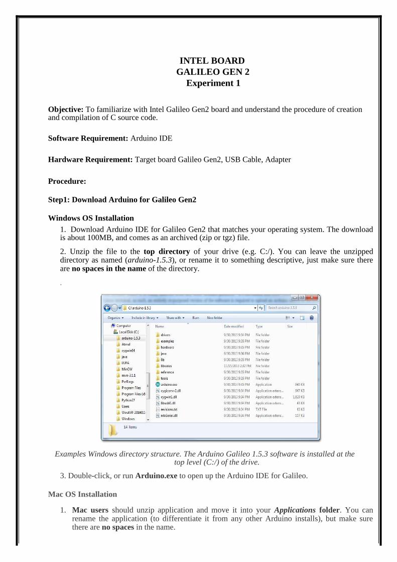
2. Unzip the file to the top directory of your drive (e.g. C:/). You can leave the unzipped directory as named (arduino-1.5.3), or rename it to something descriptive, just make sure there are no spaces in the name of the directory.
.
Examples Windows directory structure. The Arduino Galileo 1.5.3 software is installed at the top level (C:/) of the drive.
3. Double-click, or run Arduino.exe to open up the Arduino IDE for Galileo.
Mac OS Installation
1. Mac users should unzip application and move it into your Applications folder. You can rename the application (to differentiate it from any other Arduino installs), but make sure there are no spaces in the name.
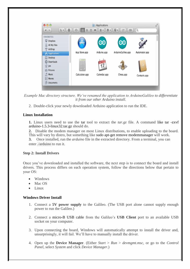
Example Mac directory structure. We’ve renamed the application to ArduinoGalileo to differentiate
it from our other Arduino install.
2. Double-click your newly downloaded Arduino application to run the IDE.
Linux Installation
1. Linux users need to use the tar tool to extract the tar.gz file. A command like tar -zxvf arduino-1.5.3-linux32.tar.gz should do. 2. Disable the modem manager on most Linux distributions, to enable uploading to the board. This will vary by distro, but something like sudo apt-get remove modemmanager will work. 3. Once installed, run the arduino file in the extracted directory. From a terminal, you can enter ./arduino to run it.
Step 2: Install Drivers
Once you’ve downloaded and installed the software, the next step is to connect the board and install drivers. This process differs on each operation system, follow the directions below that pertain to your OS:
Windows
Mac OS
Linux
Windows Driver Install
1. Connect a 5V power supply to the Galileo. (The USB port alone cannot supply enough power to run the Galileo.)
2. Connect a micro-B USB cable from the Galileo’s USB Client port to an available USB
socket on your computer.
3. Upon connecting the board, Windows will automatically attempt to install the driver and,
unsurprisingly, it will fail. We’ll have to manually install the driver.
4. Open up the Device Manager. (Either Start > Run > devmgmt.msc, or go to the Control
Panel, select System and click Device Manager.)

5. Locate the Gadget Serial v2.4 device, under the Other devices tree. Right-click that and
select Update Driver Software…
6. On the first window that pops up, click Browse my computer for driver software. And on the next page selectBrowse… and navigate to the hardware\arduino\x86\tools folder within
your Arduino Galileo software installation. Then click Next.
7. Click Install on the next Windows Security window that pops up. And, after a number of
loading-bar-scrolls, the installation should complete and you should be greeted with a Windows has successfully updated your driver software window.
8. Look back at the Device Manager, under the Ports tree now. There should be an entry for
Galileo (COM #). Remember which COM # your Galileo is assigned, it’ll be important for Arduino sketch uploading and the next step, updating firmware.
Mac OS Driver Install Mac has built-in driver support for the Galileo, so this setup should be easy. Follow the steps below to install the board on your machine:
1. Begin by connecting 5V power to the Galileo.
2. Then connect a micro-B USB Cable from the USB Client port on the Galileo to an available USB socket on your computer.
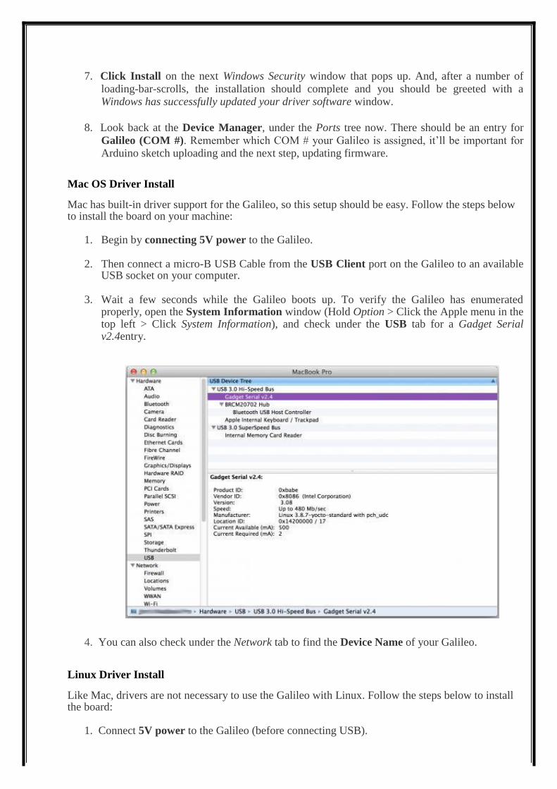
3. Wait a few seconds while the Galileo boots up. To verify the Galileo has enumerated
properly, open the System Information window (Hold Option > Click the Apple menu in the top left > Click System Information), and check under the USB tab for a Gadget Serial v2.4entry.
4. You can also check under the Network tab to find the Device Name of your Galileo. Linux Driver Install Like Mac, drivers are not necessary to use the Galileo with Linux. Follow the steps below to install the board:
1. Connect 5V power to the Galileo (before connecting USB).
2. Connect a micro-B USB cable from the USB Client port on the Galileo to an available socket
on your computer.
3. Open a terminal and type ls /dev/ttyACM*
4. Take note of the port number that the Galileo is assigned to, you’ll need that when you upload code to the board.
Step3: Updating Firmware Updating the Galileo firmware is a good first step to take after driver installation. It helps to prove that your software and drivers are set up correctly, and it prepares your Galileo board with the most up-to-date firmware available. Follow the steps below to update your Galileo board’s firmware.
a) Reboot the Galileo (No SD Cards!) To reboot the Galileo, first unplug the USB cable. Then unplug the 5V adapter from the board. If there is an SD card in the Galileo, remove it before powering the board back up. To power the board back up, make sure you plug the 5V cable in first, then plug in a USB cable into the USB Client port.
b) Set Up the Arduino Galileo IDE Open up the Galileo-specific Arduino software you downloaded earlier. Mac users can double-click the application file, Windows users should run the Arduino.exe file at the top level of the unzipped folder.
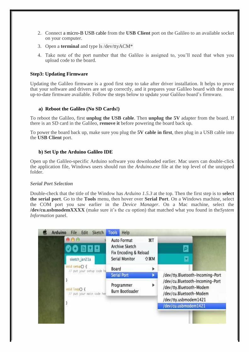
Serial Port Selection Double-check that the title of the Window has Arduino 1.5.3 at the top. Then the first step is to select the serial port. Go to the Tools menu, then hover over Serial Port. On a Windows machine, select the COM port you saw earlier in the Device Manager. On a Mac machine, select the /dev/cu.usbmodemXXXX (make sure it’s the cu option) that matched what you found in theSystem Information panel.
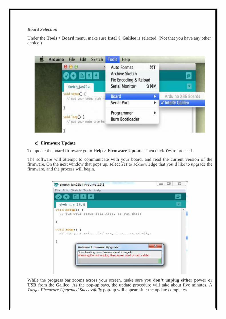
Board Selection Under the Tools > Board menu, make sure Intel ® Galileo is selected. (Not that you have any other choice.)
c) Firmware Update To update the board firmware go to Help > Firmware Update. Then click Yes to proceed. The software will attempt to communicate with your board, and read the current version of the firmware. On the next window that pops up, select Yes to acknowledge that you’d like to upgrade the firmware, and the process will begin. While the progress bar zooms across your screen, make sure you don’t unplug either power or USB from the Galileo. As the pop-up says, the update procedure will take about five minutes. A Target Firmware Upgraded Successfully pop-up will appear after the update completes.
Uploading Blink As always, the first program to be uploaded to a board is the “Hello, world” of microcontrollers - Blink.
To open the Blink example, go to the File > Examples > 01.Basics > Blink.
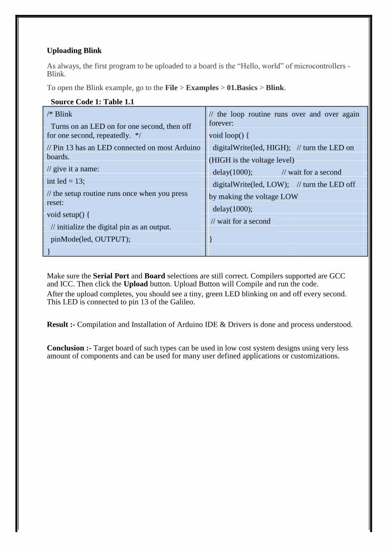
Source Code 1: Table 1.1
/* Blink // the loop routine runs over and over again
Turns on an LED on for one second, then off forever:
for one second, repeatedly. */ void loop() {
// Pin 13 has an LED connected on most Arduino digitalWrite(led, HIGH); // turn the LED on
boards. (HIGH is the voltage level)
// give it a name:
delay(1000); // wait for a second
int led = 13;
digitalWrite(led, LOW); // turn the LED off
// the setup routine runs once when you press
by making the voltage LOW
reset:
delay(1000);
void setup() {
// wait for a second
// initialize the digital pin as an output.
}
pinMode(led, OUTPUT);
}
Make sure the Serial Port and Board selections are still correct. Compilers supported are GCC and ICC. Then click the Upload button. Upload Button will Compile and run the code. After the upload completes, you should see a tiny, green LED blinking on and off every second. This LED is connected to pin 13 of the Galileo.
Result :- Compilation and Installation of Arduino IDE & Drivers is done and process understood.
Conclusion :- Target board of such types can be used in low cost system designs using very less amount of components and can be used for many user defined applications or customizations.
Experiment 2
Objective: To write C source code to Interface LCD with Intel Galileo Gen 2 and display IGDTUW on LCD Display.
Software Requirement: Arduino IDE for Galileo Gen2
Hardware Requirement: Target board Intel Galileo Gen2, USB Cable, LCD, Connecting wires, adapter
Procedure:
1. Write desired C source code 2. Compile the code as described in experiment1.
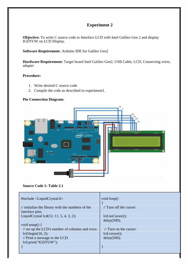
Pin Connection Diagram:
Source Code 1: Table 2.1
#include <LiquidCrystal.h> void loop()
{
// initialize the library with the numbers of the // Turn off the cursor:
interface pins
LiquidCrystal lcd(12, 11, 5, 4, 3, 2); lcd.noCursor();
delay(500);
void setup() {
// set up the LCD's number of columns and rows: // Turn on the cursor:
lcd.begin(16, 2); lcd.cursor();
// Print a message to the LCD. delay(500);
lcd.print("IGDTUW");
} }
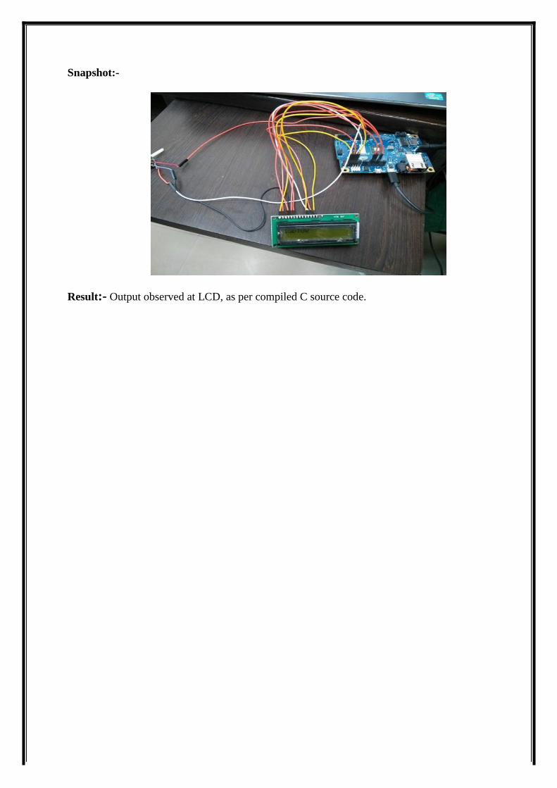
Snapshot:-
Result:- Output observed at LCD, as per compiled C source code.
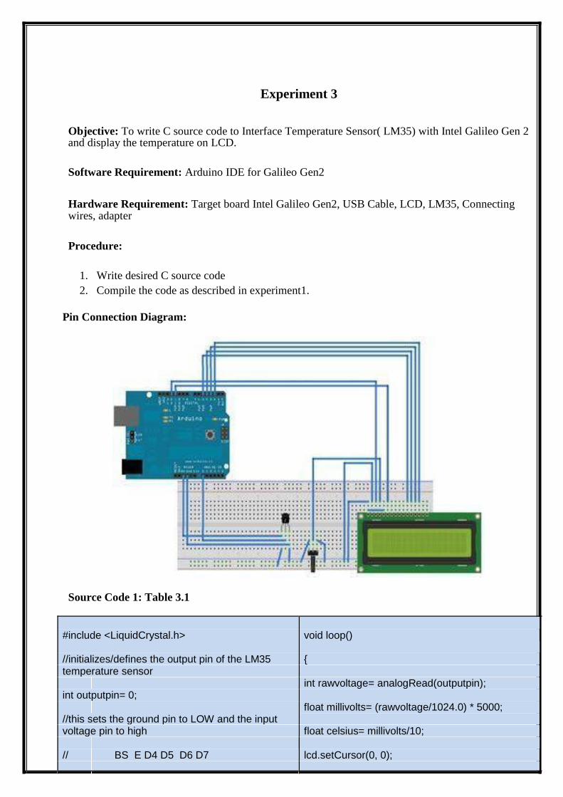
Experiment 3
Objective: To write C source code to Interface Temperature Sensor( LM35) with Intel Galileo Gen 2 and display the temperature on LCD.
Software Requirement: Arduino IDE for Galileo Gen2
Hardware Requirement: Target board Intel Galileo Gen2, USB Cable, LCD, LM35, Connecting wires, adapter
Procedure:
1. Write desired C source code 2. Compile the code as described in experiment1.
Pin Connection Diagram:
Source Code 1: Table 3.1
#include <LiquidCrystal.h> void loop()
//initializes/defines the output pin of the LM35 { temperature sensor
int rawvoltage= analogRead(outputpin);
int outputpin= 0;
float millivolts= (rawvoltage/1024.0) * 5000;
//this sets the ground pin to LOW and the input
voltage pin to high float celsius= millivolts/10;
// BS E D4 D5 D6 D7 lcd.setCursor(0, 0);
LiquidCrystal lcd(12, 11, 5, 4, 3, 2); lcd.print(" BY IGDTUW:ESENS,");
void setup() lcd.setCursor(0, 1); {
lcd.print(celsius);
lcd.begin(16,2);
lcd.print("C");
}
delay(1000);
//main loop
}
}
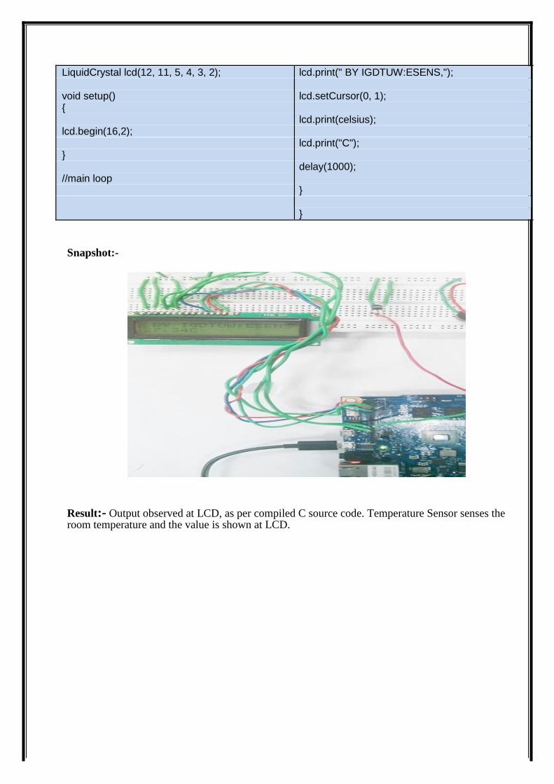
Snapshot:-
Result:- Output observed at LCD, as per compiled C source code. Temperature Sensor senses the room temperature and the value is shown at LCD.
Experiment 4
Objective: To write C source code to Interface Temperature Sensor (LM35), Piezo Buzzer & LCD Display with Intel Galileo Gen 2 .
Software Requirement: Arduino IDE for Galileo Gen2
Hardware Requirement: Target board Intel Galileo Gen2, USB Cable, LM35, LCD , piezo buzzer, Connecting wires, adapter
Procedure:
1. Write desired C source code 2. Compile the code as described in experiment1.
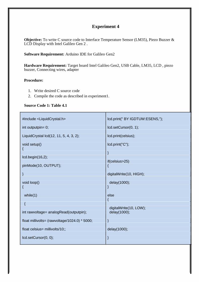
Source Code 1: Table 4.1
#include <LiquidCrystal.h> lcd.print(" BY IGDTUW:ESENS,");
int outputpin= 0; lcd.setCursor(0, 1);
LiquidCrystal lcd(12, 11, 5, 4, 3, 2); lcd.print(celsius);
void setup() lcd.print("C"); {
}
lcd.begin(16,2);
if(celsius>25)
pinMode(10, OUTPUT); {
} digitalWrite(10, HIGH);
void loop() delay(1000); { }
while(1) else {
{
digitalWrite(10, LOW);
int rawvoltage= analogRead(outputpin); delay(1000);
float millivolts= (rawvoltage/1024.0) * 5000; }
float celsius= millivolts/10;; delay(1000);
lcd.setCursor(0, 0); }
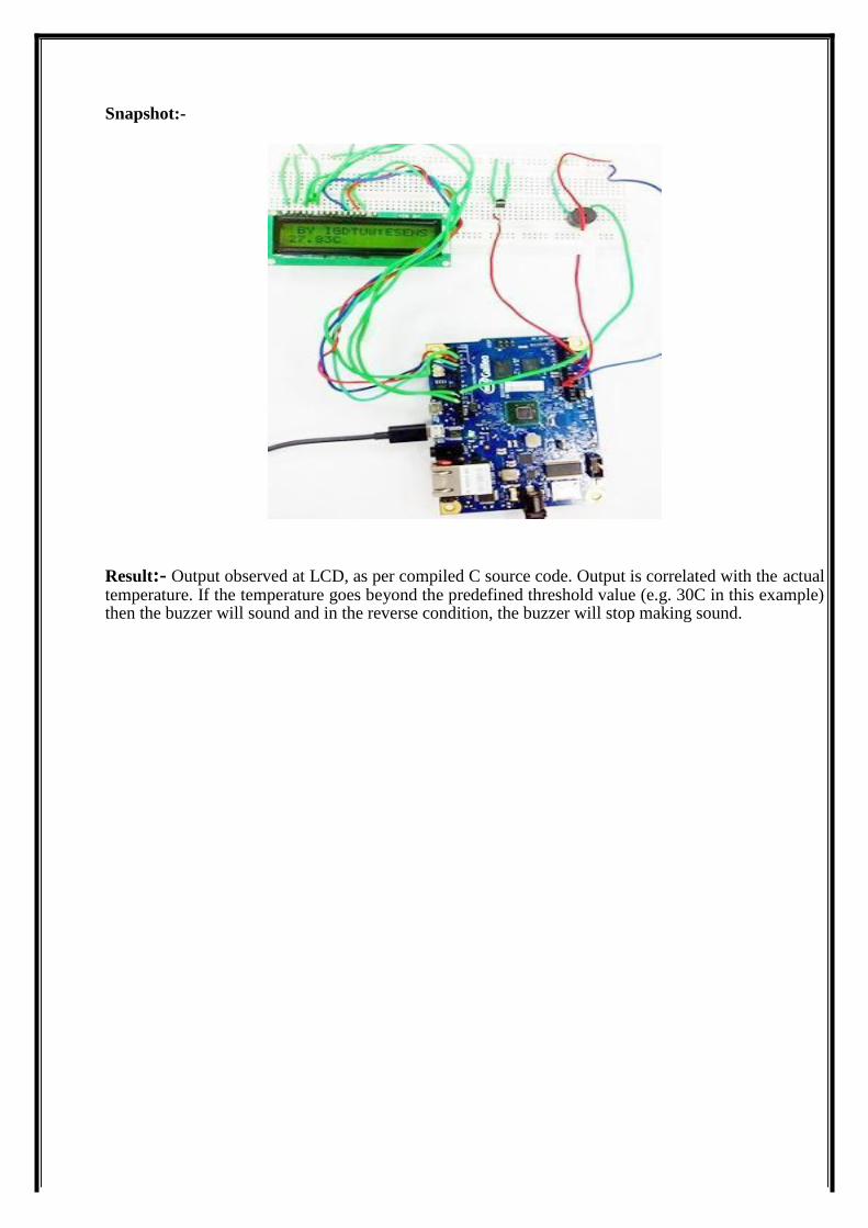
Snapshot:-
Result:- Output observed at LCD, as per compiled C source code. Output is correlated with the actual temperature. If the temperature goes beyond the predefined threshold value (e.g. 30C in this example) then the buzzer will sound and in the reverse condition, the buzzer will stop making sound.
Experiment 5
Objective: To write C source code to Interface Sound Detector with Intel Galileo Gen 2 .
Software Requirement: Arduino IDE for Galileo Gen2
Hardware Requirement: Target board Intel Galileo Gen2, USB Cable, Sound Detector, Connecting wires, Adapter
Procedure:
1. Write desired C source code 2. Compile the code as described in experiment1.
Source Code 1: Table 5.1
int sensorPin = A0; // select the input pin for the void loop ()
potentiometer {
int ledPin = 13; // select the pin for the LED sensorValue = analogRead (sensorPin);
int sensorValue = 0; // variable to store the value digitalWrite (ledPin, HIGH);
coming from the sensor delay (sensorValue);
void setup () digitalWrite (ledPin, LOW);
{ delay (sensorValue);
pinMode (ledPin, OUTPUT); Serial.println (sensorValue, DEC);
Serial.begin (9600); } }
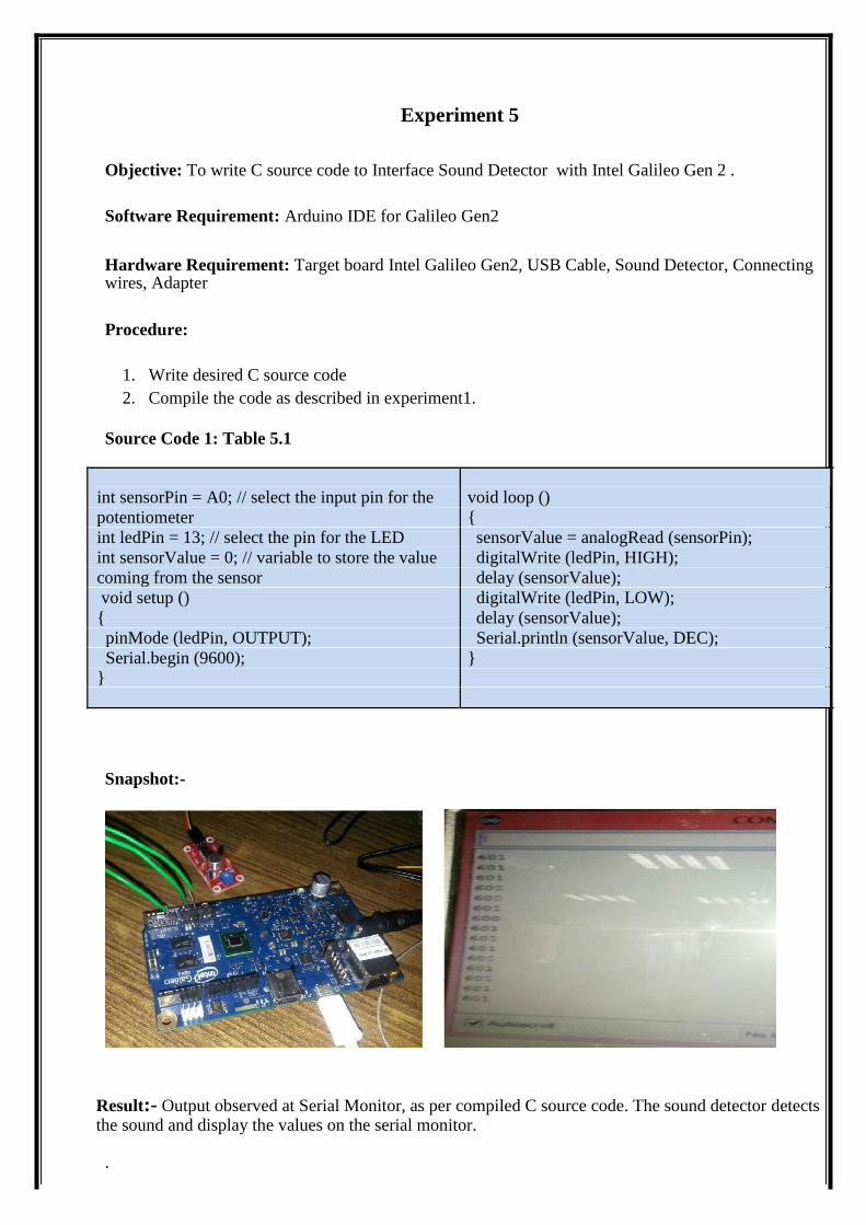
Snapshot:-
Result:- Output observed at Serial Monitor, as per compiled C source code. The sound detector detects the sound and display the values on the serial monitor.
.
Experiment 6
Objective: To write C source code to Interface Bluetooth Module with Intel Galileo Gen 2 and showing communication between Galileo Gen2 & Android Device .
Software Requirement: Arduino IDE for Galileo Gen2, Bluetooth SPP Manager for Android device.
Hardware Requirement: Target board Intel Galileo Gen2, USB Cable, Bluetooth Module-HC-05, Connecting wires, Adapter
Procedure:
1. Write desired C source code 2. Compile the code as described in experiment1.
Source Code 1: Table 6.1
void setup() Serial1.begin(9600); {
// put your setup code here, to run once: Serial1.println("Bluetooth Connected on mobile
// Open serial communications and wait for port device");
to open: }
Serial.begin(9600); void loop()
while (!Serial) {
{ if (Serial1.available())
; // wait for serial port to connect. Serial.write(Serial1.read());
} if (Serial.available())
Serial.println("Bluetooth Connected on serial Serial1.write(Serial.read());
monitor"); } // set the data rate for the SoftwareSerial port
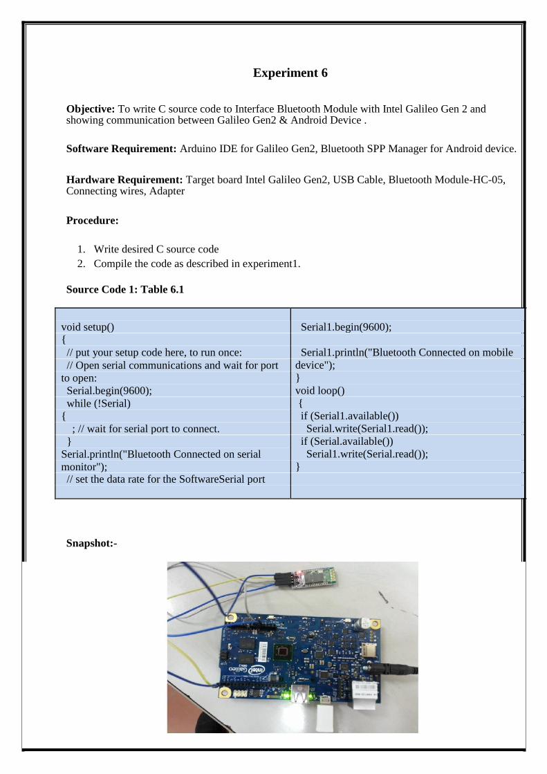
Snapshot:-
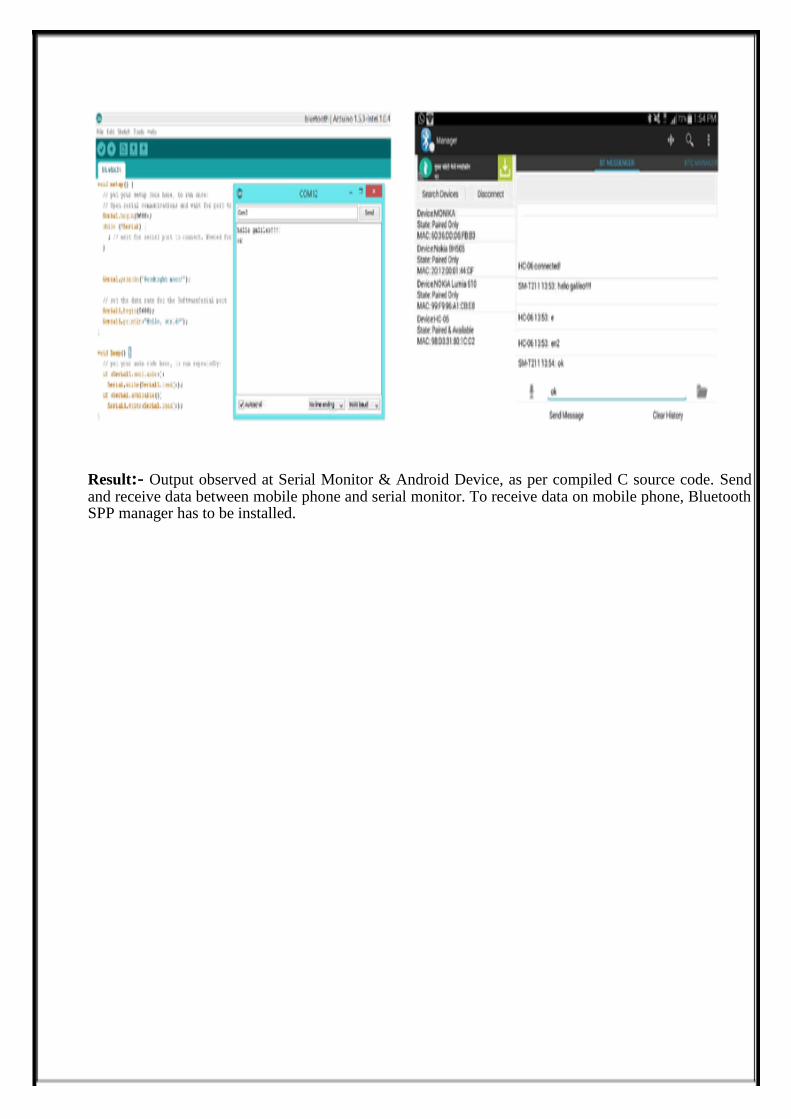
Result:- Output observed at Serial Monitor & Android Device, as per compiled C source code. Send and receive data between mobile phone and serial monitor. To receive data on mobile phone, Bluetooth SPP manager has to be installed.
Experiment 7
Objective: To write C source code to Interface Bluetooth Module & Temperature sensor with Intel Galileo Gen 2 and display temperature values from serial monitor to mobile device.
Software Requirement: Arduino IDE for Galileo Gen2, Bluetooth SPP Manager for Android device.
Hardware Requirement: Target board Intel Galileo Gen2, USB Cable, Bluetooth Module-HC-05,Temperature sensor, Connecting wires, Adapter
Procedure:
1. Write desired C source code 2. Compile the code as described in experiment1.
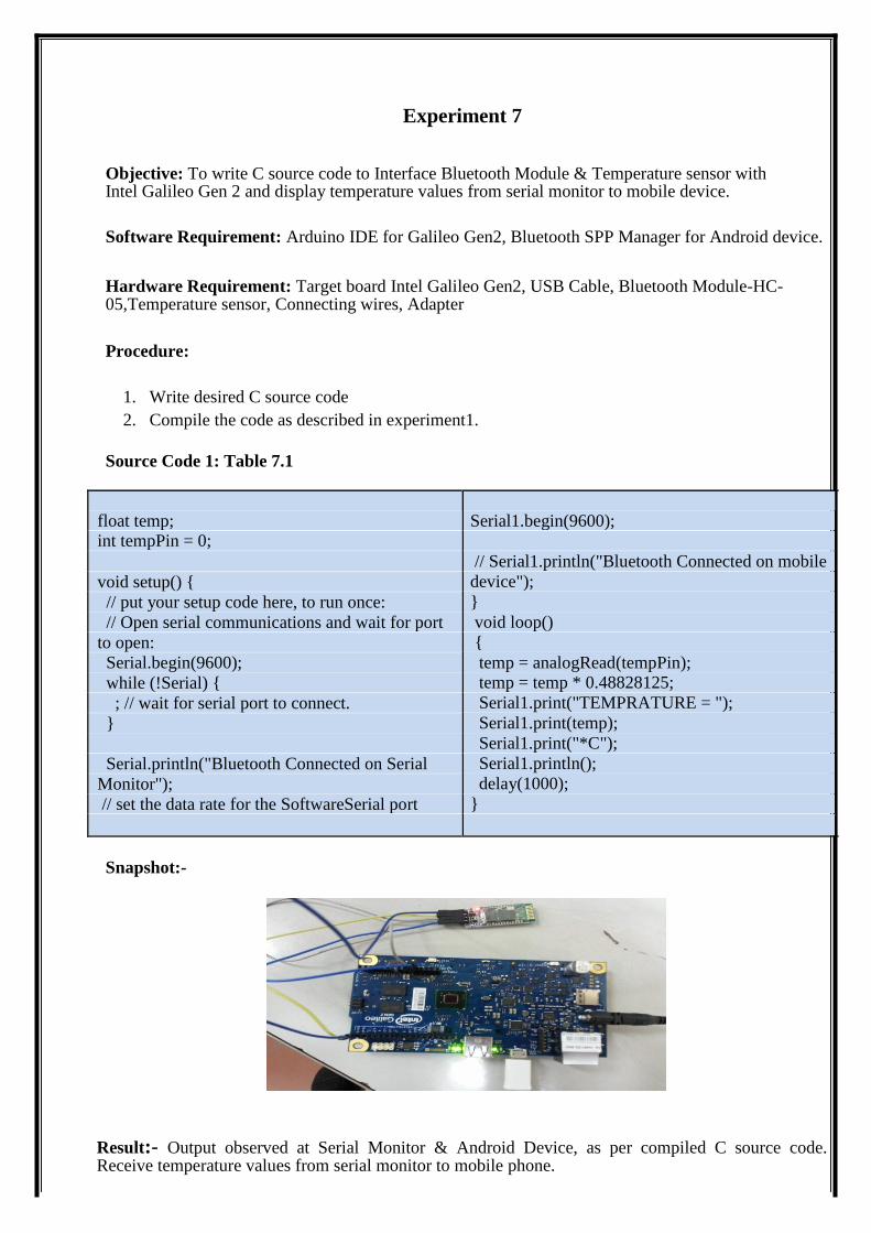
Source Code 1: Table 7.1
float temp; Serial1.begin(9600); int tempPin = 0;
// Serial1.println("Bluetooth Connected on mobile
void setup() { device");
// put your setup code here, to run once: }
// Open serial communications and wait for port void loop()
to open: {
Serial.begin(9600); temp = analogRead(tempPin);
while (!Serial) { temp = temp * 0.48828125;
; // wait for serial port to connect. Serial1.print("TEMPRATURE = ");
} Serial1.print(temp);
Serial1.print("*C");
Serial.println("Bluetooth Connected on Serial Serial1.println();
Monitor"); delay(1000);
// set the data rate for the SoftwareSerial port }
Snapshot:-
Result:- Output observed at Serial Monitor & Android Device, as per compiled C source code. Receive temperature values from serial monitor to mobile phone.
Experiment 8
Objective: To Implement A Motion Alarm Circuit Using Intel Galileo Gen2 Board Using Motion Sensor And Buzzer. Software Requirement: Arduino IDE for Galileo Gen2 Hardware Requirement: Target board Intel Galileo Gen2, USB Cable, PIR Motion Sensor, Connecting wires, Adapter
Procedure:
1. Write desired C source code 2. Compile the code as described in experiment1.
Theory:
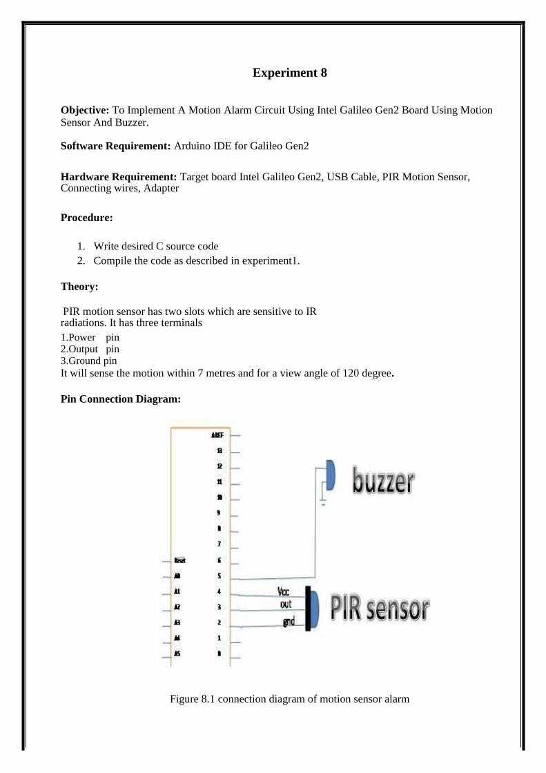
PIR motion sensor has two slots which are sensitive to IR radiations. It has three terminals 1.Power pin 2.Output pin 3.Ground pin It will sense the motion within 7 metres and for a view angle of 120 degree.
Pin Connection Diagram:
Figure 8.1 connection diagram of motion sensor alarm
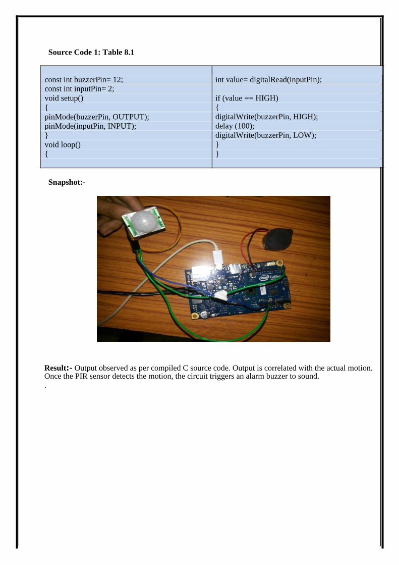
Source Code 1: Table 8.1
const int buzzerPin= 12; int value= digitalRead(inputPin); const int inputPin= 2;
void setup() if (value == HIGH)
{ {
pinMode(buzzerPin, OUTPUT); digitalWrite(buzzerPin, HIGH);
pinMode(inputPin, INPUT); delay (100);
} digitalWrite(buzzerPin, LOW);
void loop() }
{ }
Snapshot:-
Result:- Output observed as per compiled C source code. Output is correlated with the actual motion. Once the PIR sensor detects the motion, the circuit triggers an alarm buzzer to sound. .
Experiment 9
Objective: To write C source code to Interface Temperature Sensor & I2V DC fan with Intel Galileo Gen2. Software Requirement: Arduino IDE for Galileo Gen2
Hardware Requirement: Intel Galileo Gen2 board, LM35 temperature sensor, Connecting wires, Adapter, USB cable, DC Fan
Procedure:
1. Write desired C source code 2. Compile the code as described in experiment1.
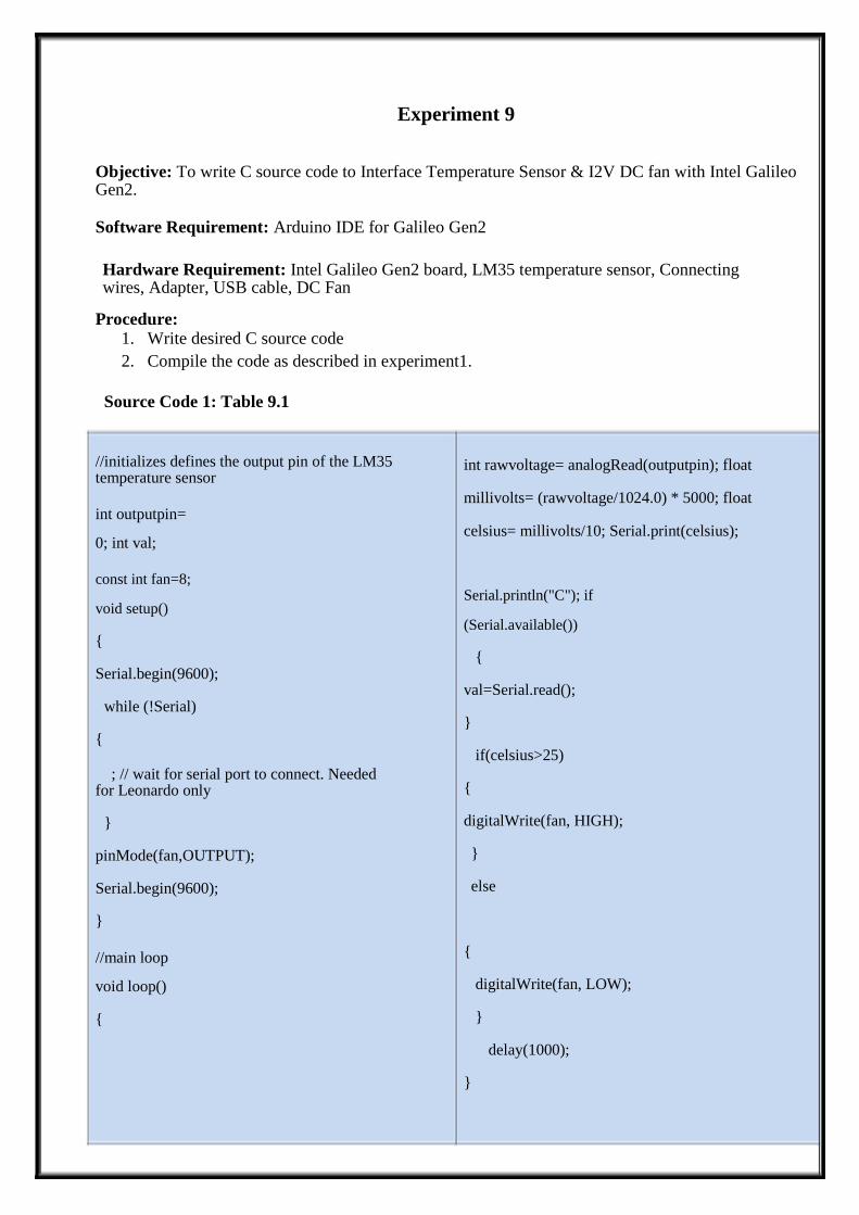
Source Code 1: Table 9.1
//initializes defines the output pin of the LM35 temperature sensor int outputpin=
0; int val;
const int fan=8;
void setup() { Serial.begin(9600);
while (!Serial) {
; // wait for serial port to connect. Needed for Leonardo only
} pinMode(fan,OUTPUT); Serial.begin(9600); } //main loop
void loop() {
int rawvoltage= analogRead(outputpin); float
millivolts= (rawvoltage/1024.0) * 5000; float
celsius= millivolts/10; Serial.print(celsius);
Serial.println("C"); if
(Serial.available())
{ val=Serial.read(); }
if(celsius>25) { digitalWrite(fan, HIGH); }
else
{
digitalWrite(fan, LOW);
}
delay(1000); }
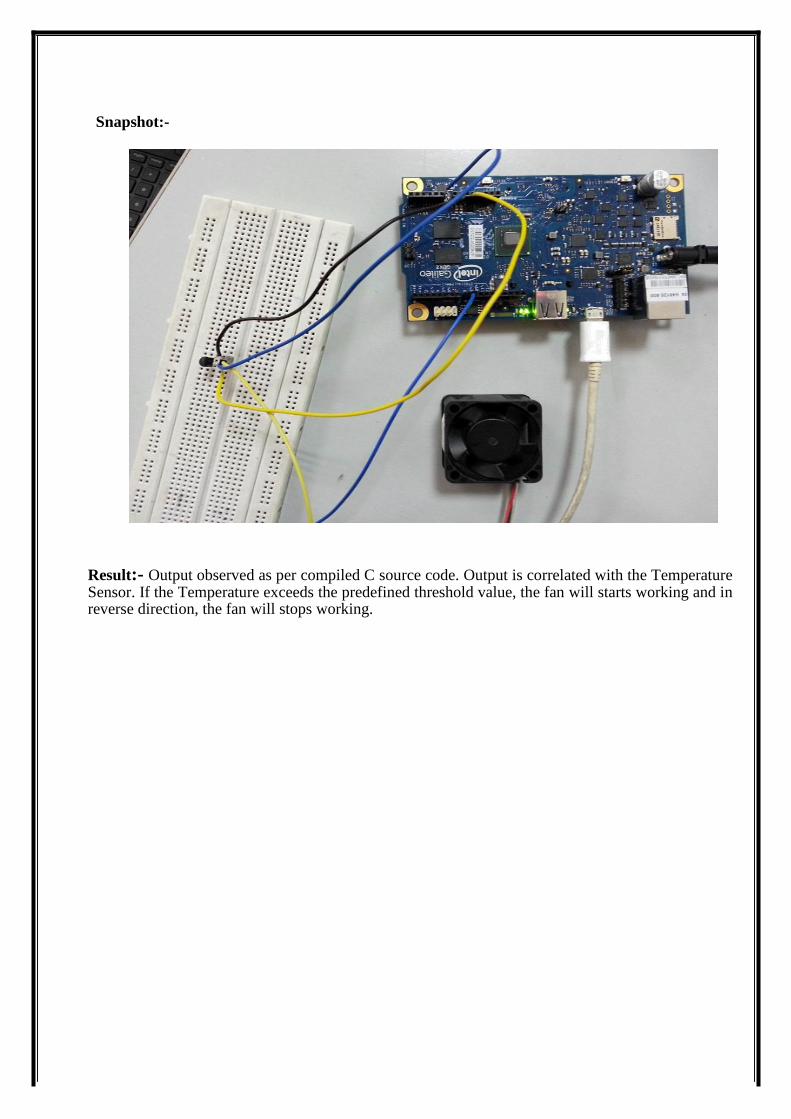
Snapshot:-
Result:- Output observed as per compiled C source code. Output is correlated with the Temperature Sensor. If the Temperature exceeds the predefined threshold value, the fan will starts working and in reverse direction, the fan will stops working.
Experiment 10
Objective: To write C source code to Perform Alcohol Sensor Interfacing With Intel Galileo Gen2.
Software Requirement: Arduino IDE for Galileo Gen2
Hardware Requirement: Intel Galileo Gen2 board, Alcohol Sensor Mq3, Connecting wires, Adapter, USB cable.
Procedure:
1. Write desired C source code 2. Compile the code as described in experiment1.
Theory: This alcohol sensor detects the concentration of alcohol gas in the air and outputs its reading as an
analog voltage. The concentration sensing range of 0.04 mg/L to 4 mg/L is suitable for breathalyzers.
The sensor can operate at temperatures from -10 to 50°C and consumes less than 150 mA at 5 V.
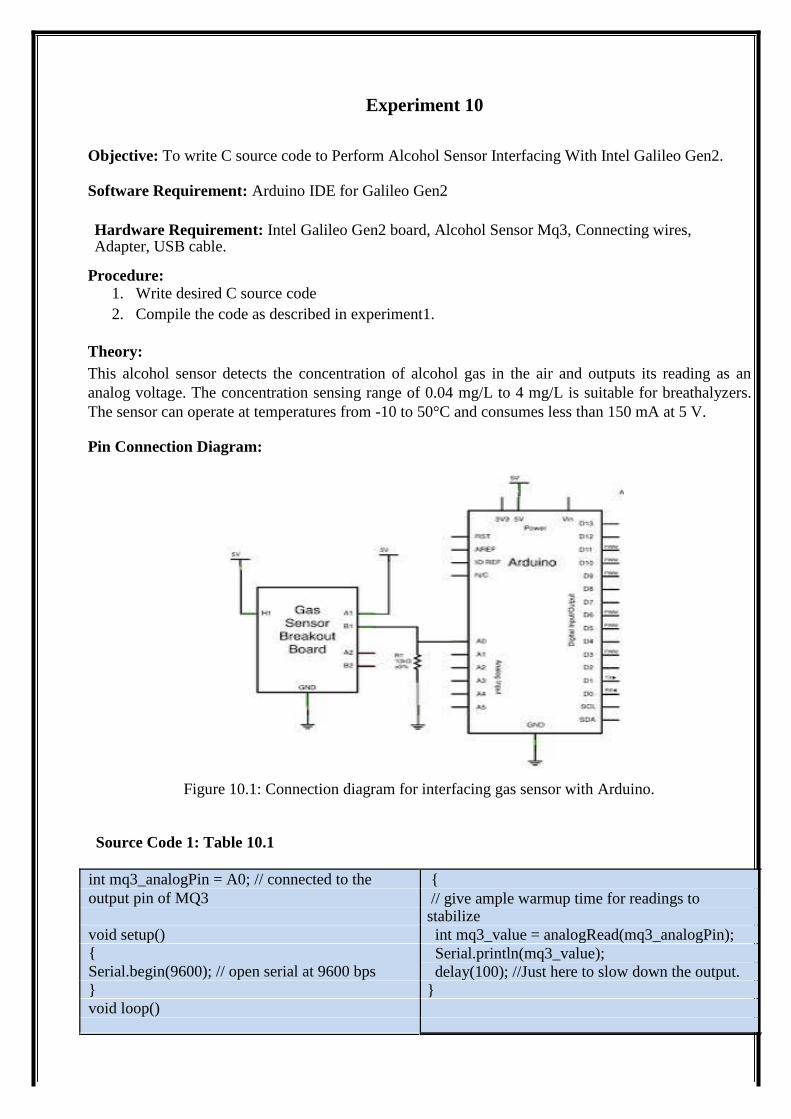
Pin Connection Diagram:
Figure 10.1: Connection diagram for interfacing gas sensor with Arduino.
Source Code 1: Table 10.1
int mq3_analogPin = A0; // connected to the {
output pin of MQ3 // give ample warmup time for readings to stabilize
void setup() int mq3_value = analogRead(mq3_analogPin);
{ Serial.println(mq3_value);
Serial.begin(9600); // open serial at 9600 bps delay(100); //Just here to slow down the output.
} }
void loop()
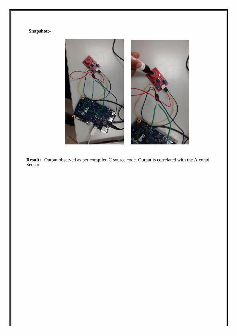
Snapshot:-
Result:- Output observed as per compiled C source code. Output is correlated with the Alcohol Sensor.