design criteria and exposure zones - transportation
TRANSCRIPT

Design Criteria and Exposure Zones
IBC Workshop: W-8 Service Life Design
Mike Bartholomew, P.E.
Jacobs
June 14, 2018

Presentation Overview
• This part of the worked example covers:
– Overview of the bridge considered in this design
example;
– Overview of design criteria; and
– Definition of exposure zones.
2

Location of the Bridge
• Location:
– New York City.
– Highway under the bridge.
– Urban environment with periods of snow and freeze-
thaw cycles.
– Annual mean temperature of 11.5⁰C (52.7⁰F).
– Heavy use of de-icing salts.
– Some sulfate present in soil: 0.14% by mass of water
soluble sulfate was measured.
3

Arrangement of the Bridge
• General bridge characteristics:
– 264 ft. steel girder bridge with two spans (139 ft. and 125 ft.).
– Over the abutments, the girders are supported on elastomeric bearings and at
the piers, the girders are supported on fixed bearings.
– Deck and girders are continuous over the pier.
– Uncoated reinforcement (black steel) used everywhere.
4
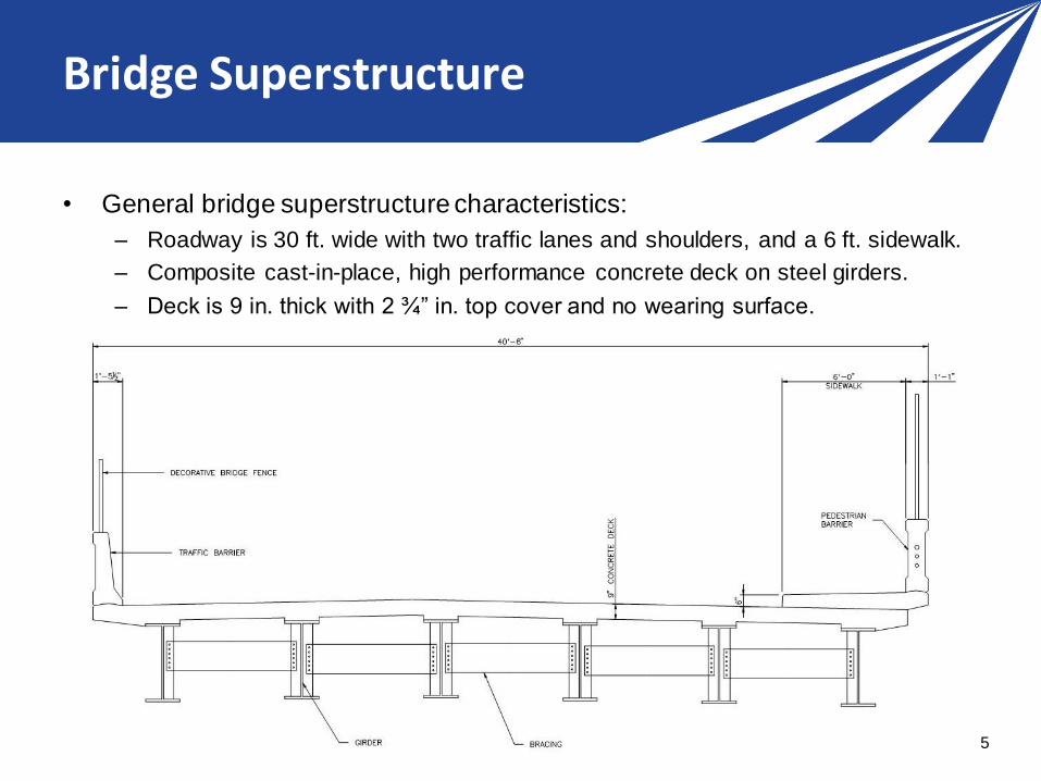
Bridge Superstructure
• General bridge superstructure characteristics:
– Roadway is 30 ft. wide with two traffic lanes and shoulders, and a 6 ft. sidewalk.
– Composite cast-in-place, high performance concrete deck on steel girders.
– Deck is 9 in. thick with 2 ¾” in. top cover and no wearing surface.
5

Bridge Substructure
• General bridge substructure characteristics:
– The central pier has three columns each supported by a pile cap and steel piles
driven into bedrock:
– Uncoated reinforcement (black steel) used everywhere.
– No mass concrete.
6

Bridge Substructure
• General bridge substructure characteristics:
– Abutments are supported by a reinforced concrete tangent pile wall:
– Full height precast abutment wall in front of the abutments protect them.
– Expansion joints are located between abutments and concrete deck.
7

Service Life Requirements
• Service life requirements:
– Service life is defined as the period without major repairs or maintenance.
Normal routine maintenance is expected.
– Non-replaceable components must meet a minimum service life of 75 years.
– Replaceable components must meet a minimum service life as below:
8
Non-Replaceable Components Minimum Service Life (years)Foundations, abutments, piers, structural steel, and deck
75
Replaceable ComponentsMinimum Service Life (years)
Bridge bearings 50Expansion joints 30Painting 25Barriers 50

Service Life Requirements
• fib Bulletin 34 – Model Code for Service Life Design
9
Service Life Design Procedure
• Recommended service life design procedure:
1. Define exposure zones for all bridge components;
2. Define deterioration mechanisms for each exposure
zone;
3. Define mitigation methods for deterioration
mechanisms for concrete components; and
4. Define mitigation methods for deterioration
mechanisms for steel components.
10

Defined Exposure Conditions
Buried: Zone permanently buried in soil. Abutment and tangent pile surfaces exposed to soil, pile
cap, steel piles.
Atmospheric: Zone not exposed to soil or de-icing salts. Bottom surface of deck, wing wall
surfaces and tangent pile surfaces exposed to atmospheric air.
Indirect de-icing salts: Zone subject to runoff water or spray containing de-icing salts, typically areas
under and within 10 ft. of expansion joints or within 6 ft. to 20 ft. vertically of a
roadway. Girder, bracing, pier column, pier cap, abutment wall.
Direct de-icing salts: Zone directly exposed to the use of de-icing salts. Top surface of deck, traffic
barrier, pedestrian barrier, piers directly next to roadway up to 6 ft. vertically of
the roadway, fencing.
11

Defined Exposure Conditions
• American Concrete Institute ACI 318-2014 –
Building Code Requirements for Structural
Concrete
– Chapter 19 – Concrete Design and Durability
Requirements
• Table 19.3.1.1 – Exposure categories and classes
12

ACI 318-14 Exposure Classes
13

ACI 318-14 Exposure Classes
14

ACI 318-14 Exposure Classes
15

Defined Exposure Conditions
• European Standard EN 206:2013 – Concrete –
Specification, performance, production, and
conformity
– 4.1 Exposure classes related to environmental
actions
• Table 1 – Exposure Classes
• Table 2 – Limiting values for exposure classes for
chemical attack from natural soil and groundwater
16

EN 206:2013 Exposure Classes
Table 1 – Exposure classes
17

EN 206:2013 Exposure Classes
18

Defined Exposure Conditions
• International Standard ISO 12944 – Paints and
varnishes – Corrosion protection of steel
structures by protective paint systems – Part 2:
Classifications of environments
– 5 Classification of environments
• Table 1 – Atmospheric-corrosivity categories and
examples of typical environments
• Table 2 – Categories for Soil and Water
19

ISO 12944 – Part 2 Atmospheric Exposures
20

ISO 12944 – Part 2 Water and Soil Exposures
21

Exposure Zones Color Code
• Exposure zones for longitudinal section of the
Bridge:
22

Exposure Zones Color Code
• Exposure zones for superstructure:
23

Exposure Zones Color Code
• Exposure zones for substructure:
24

Exposure Zones Color Code
• Exposure zones for abutments:
25
Collecting Environmental Data
• Climate/Weather
– Temperature
– Precipitation (Rain and/or Snow)
– Freeze-Thaw Cycles
– Relative Humidity
• Surface Chloride Concentration from De-Icing
– Historical Data
– Chloride Profiles from Existing/Nearby Structures
26

NOAA Climate Data
27
https://www.ncdc.noaa.gov/cdo-web/
Select

NOAA Climate Data
28
Select

NOAA Climate Data
29
Research and Development Implementation

NOAA Climate Data
30
Research and Development ImplementationSelect
Central
Park
station

NOAA Climate Data
31
Research and Development ImplementationSelect

NOAA Climate Data
32
Research and Development Implementation

NOAA Climate Data (pdf)
33
Research and Development Implementation

NOAA Climate Data
34
Research and Development Implementation

NOAA Climate Data
• Annual
Snowfall
• Freeze-Thaw
Cycles
(DT32 - DX32)
35

NOAA Climate Data (CSV)
• File converted to Excel for data manipulation
36
Rain
>0.1"
Snow
depth >1"
Snow-
fall
Tmin
≤32°F
Tmax
≥32°F
Snowd
epth
Snow-
fall
Rain-
fall
Rain-
fall
Snow-
fall
DATE DP01 DSND DSNW DT32 DX32 EMSD EMSN EMXP PRCP SNOW TAVG TMAX TMIN
1960 115 31 9 99 19 15 12.5 3.56 46.43 41.6 54 61.5 46.5
1961 119 43 9 74 22 24 11.4 2.1 39.36 43.8 55 62.7 47.4
1962 109 17 6 79 22 3 2.9 2.33 37.17 15 53.4 61.5 45.3
1963 115 25 9 78 30 6 6 2.96 34.31 23 53.5 61.8 45.2
1964 113 28 10 75 13 13 11.5 1.29 33.02 36.5 54.5 62.7 46.4
1965 103 21 8 71 19 6 6.3 1.35 26.12 21.3 54.2 62 46.3
1966 116 28 9 77 19 8 6.7 5.54 39.91 30.4 55 63 47.1
1967 126 28 13 86 20 13 12.5 2.15 49.14 51.2 52.9 60.6 45.3
1968 109 21 5 87 26 5 5.5 3.99 43.6 17.8 54 62 46.1
1969 120 34 9 90 17 15 14 3.32 48.54 30 54.8 62.1 47.4
Extreme Maximums (in) Total Annual (in) Temperature (°F)# of Days

Summary of Environmental Data
• Climate/Weather (Annual Mean Values)
– Temperature – 55.1˚F = 12.8˚C (Std. Dev. = 0.6˚C)
– Snowfall – 27 inches (Std. Dev. = 14.3 inches)
– Freeze-Thaw Cycles – 53.6 (Std. Dev. = 9.3)
• Surface Chloride Concentration from De-Icing
– Taken from Historical Data – 4% mass of
cementitious materials (Std. Dev. = 2%)
37

Questions?
Implementation Leads:
• Patricia Bush, AASHTO Program Manager for
Engineering, [email protected]
• Raj Ailaney, FHWA Senior Bridge Engineer,
Subject Matter Expert Team:
• Mike Bartholomew, Jacobs,
• Anne-Marie Langlois, COWI North America,
Resource: AASHTO’s R19A Product Page
• http://shrp2.transportation.org/Pages/ServiceLifeDesignf
orBridges.aspx